Embed Size (px)
Citation preview

Test Report LP0002 (100-06-28)
Summit Data Communications Device Name:SDC-MSD40NBT
Brand: Summit Data Communications Model: SDC-SSD40NBT
GRANTEE: Summit Data Communications 526 South Main St. Suite 805 Akron, OH 44311 TEST SITE: Elliott Laboratories 41039 Boyce Road Fremont, CA 94538 REPORT DATE: March 20, 2012 FINAL TEST DATE: October 19, 20 and 21 and November 19 and
24, 2010 and May 11, August 2, 4, 10, 12, 13, 16, 17, 18 19, 20, 23, 24, 26 and October 6, 7, 19, 20 and 26 and November 3, 4, 7, 8, 9, 15, 2011
PRODUCT RECEIVED DATE: October 19, 2010 TOTAL NUMBER OF PAGES: 147 PROGRAM MGR / QUALITY ASSURANCE DELEGATE / TECHNICAL REVIEWER: FINAL REPORT PREPARER: ______________________________ ______________________________ Mark E Hill David Guidotti Staff Engineer Senior Technical Writer
Elliott Laboratories is accredited by the A2LA, certificate number 0214.26, to perform the test(s) listed in this report, except where noted otherwise. This report and the information contained herein represent the results of testing test articles identified and selected by the client performed to specifications and/or procedures selected by the client. National Technical Systems (NTS) makes no representations, expressed or implied, that such testing is adequate (or inadequate) to demonstrate efficiency, performance, reliability, or any other characteristic of the articles being tested, or similar products. This report should not be relied upon as an endorsement or certification by NTS of the equipment tested, nor does it represent any statement whatsoever as to its merchantability or fitness of the test article, or similar products, for a particular purpose. This report shall not be reproduced except in full
File R86843 Page 1 of 147

Elliott Laboratories -- EMC Department Test Report Report Date: March 20, 2012
File R86843 Page 2 of 147
REVISION HISTORY Rev# Date Comments Modified By
- 03-20-2012 First release

Elliott Laboratories -- EMC Department Test Report Report Date: March 20, 2012
File R86843 Page 3 of 147
TABLE OF CONTENTS REVISION HISTORY ................................................................................................................................................ 2 TABLE OF CONTENTS ............................................................................................................................................ 3 SCOPE .......................................................................................................................................................................... 4 OBJECTIVE ................................................................................................................................................................ 4 SUMMARY OF RESULTS ........................................................................................................................................ 5
GENERAL REQUIREMENTS – APPLICABLE TO ALL BANDS ...................................................................... 5 GENERAL TECHNICAL REQUIREMENTS ........................................................................................................ 5 DIGITAL TRANSMISSION SYSTEMS (2400 – 2483.5MHz) .............................................................................. 6 DIGITAL TRANSMISSION SYSTEMS (5725-5850 MHz)................................................................................... 7 UNII DEVICES, SECTION 4.7 ............................................................................................................................... 8
MEASUREMENT UNCERTAINTIES ................................................................................................................... 10 DEVIATIONS FROM THE STANDARD .............................................................................................................. 10 EQUIPMENT UNDER TEST (EUT) DETAILS .................................................................................................... 11
GENERAL .............................................................................................................................................................. 11 OTHER EUT DETAILS ......................................................................................................................................... 11 ANTENNA SYSTEM ............................................................................................................................................ 11 ENCLOSURE ......................................................................................................................................................... 11 MODIFICATIONS ................................................................................................................................................. 11 SUPPORT EQUIPMENT ....................................................................................................................................... 12 EUT INTERFACE PORTS .................................................................................................................................... 12 EUT OPERATION ................................................................................................................................................. 12
TEST SITE ................................................................................................................................................................. 13 GENERAL INFORMATION ................................................................................................................................. 13 CONDUCTED EMISSIONS CONSIDERATIONS .............................................................................................. 13 RADIATED EMISSIONS CONSIDERATIONS .................................................................................................. 13
MEASUREMENT INSTRUMENTATION ............................................................................................................ 14 RECEIVER SYSTEM ............................................................................................................................................ 14 INSTRUMENT CONTROL COMPUTER ............................................................................................................ 14 LINE IMPEDANCE STABILIZATION NETWORK (LISN) .............................................................................. 14 FILTERS/ATTENUATORS .................................................................................................................................. 15 ANTENNAS ........................................................................................................................................................... 15 ANTENNA MAST AND EQUIPMENT TURNTABLE ....................................................................................... 15 INSTRUMENT CALIBRATION ........................................................................................................................... 15
TEST PROCEDURES .............................................................................................................................................. 16 EUT AND CABLE PLACEMENT ........................................................................................................................ 16 CONDUCTED EMISSIONS .................................................................................................................................. 16 RADIATED EMISSIONS ...................................................................................................................................... 17 CONDUCTED EMISSIONS FROM ANTENNA PORT ...................................................................................... 20 BANDWIDTH MEASUREMENTS ...................................................................................................................... 20 SPECIFICATION LIMITS AND SAMPLE CALCULATIONS ........................................................................... 21 CONDUCTED EMISSIONS SPECIFICATION LIMITS: LP0002 SECTION 2.3 .............................................. 21 GENERAL RADIATED EMISSIONS SPECIFICATION LIMITS, LP0002 SECTION 2.8 ............................... 22 OUTPUT POWER LIMITS – DIGITAL TRANSMISSION SYSTEMS (LP0002 3.10.1) .................................. 22 TRANSMITTER RADIATED SPURIOUS EMISSIONS LIMITS (LP0002 3.10.1) ........................................... 22 OUTPUT POWER LIMITS FOR UNII DEVICES(LP0002 4.7) ......................................................................... 23 SPURIOUS EMISSIONS LIMITS –UNII DEVICES (LP0002 4.7.2) .................................................................. 23 SAMPLE CALCULATIONS - CONDUCTED EMISSIONS ............................................................................... 23 SAMPLE CALCULATIONS - RADIATED EMISSIONS ................................................................................... 24 SAMPLE CALCULATIONS - FIELD STRENGTH TO EIRP CONVERSION .................................................. 25
APPENDIX A TEST EQUIPMENT CALIBRATION DATA .............................................................................. 26 APPENDIX B TEST DATA LOG SHEETS ........................................................................................................... 33 APPENDIX C RADIATED EMISSIONS TEST CONFIGURATION PHOTOGRAPHS .............................. 141 APPENDIX D CONDUCTED EMISSIONS TEST CONFIGURATION PHOTOGRAPHS .......................... 142 APPENDIX E DETAILED PHOTOGRAPHS OF CONSTRUCTION ............................................................. 144 END OF REPORT .................................................................................................................................................. 147

Elliott Laboratories -- EMC Department Test Report Report Date: March 20, 2012
File R86843 Page 4 of 147
SCOPE An electromagnetic emissions test has been performed on the Summit Data Communications model SDC-SSD40NBT pursuant to LP0002 (100-06-28) - Technical Regulations for Low-power Radio-frequency Devices. Conducted and radiated emissions data has been collected, reduced, and analyzed within this report in accordance with measurement guidelines set forth in ANSI C63.4:2003 and LP0002 as outlined in Elliott Laboratories test procedures. The intentional radiator above has been tested in a simulated typical installation to demonstrate compliance with the relevant performance and procedural standards. Final system data was gathered in a mode that tended to maximize emissions by varying orientation of EUT, orientation of power and I/O cabling, antenna search height, and antenna polarization. Every practical effort was made to perform an impartial test using appropriate test equipment of known calibration. All pertinent factors have been applied to reach the determination of compliance. The test results recorded herein are based on a single type test of the Summit Data Communications model SDC-SSD40NBT and therefore apply only to the tested sample. The sample was selected and prepared by Ron Seide of Summit Data Communications.
OBJECTIVE
The primary objective of the manufacturer is compliance with LP0002 (100-06-28) - Technical Regulations for Low-power Radio-frequency Devices for the radiated and conducted emissions of intentional radiators. Certification is a procedure where the manufacturer or a contracted laboratory makes measurements and submits the test data and technical information for device approvals. Once the equipment authorization has been obtained, the label indicating compliance must be attached to all identical units that are subsequently manufactured.

Elliott Laboratories -- EMC Department Test Report Report Date: March 20, 2012
File R86843 Page 5 of 147
SUMMARY OF RESULTS GENERAL REQUIREMENTS – APPLICABLE TO ALL BANDS
LP0002 Section Description Measured Value /
Comments Limit / Requirement Result (margin)
2.10 (1) Users/Operational Manual -
Control, adjust, on/off operation will not cause
violation Complies
2.10 (2) Users/Operational Manual - Warnings against
adjustments of the device Complies
2.10 (3) Users/Operational Manual -
Warnings against any replacement of
components Complies
2.10 (4) Users/Operational Manual - Full Contents of Article
14-17 Complies
5.12 Channel Selection
Device was tested on the top, bottom and center channels in
each band
Measurements on three channels in each band N/A
GENERAL TECHNICAL REQUIREMENTS
LP0002 Section Description Measured Value Comments Refer to: Result
2.3 AC Conducted Emissions
31.9dBµV @ 19.501MHz (-18.1dB)
AC conducted emissions shall meet the emissions
limits detailed in 2.3 Complies
3.10.1(4) Antenna Gain See EUT Description Section
Antenna gains in excess of 6dBi may require
reduction in output power, see appropriate rule part
- Complies
3.10.1 (4) RF Connector u.FL connectors - Complies
5.20
RF Exposure Requirements
(minimum 20 cm separation)
0.024 mW/cm2 MPE shall be less than 1 mW/cm2 Complies
2.11 Radiated Spurious
Emissions –30MHz – 25 GHz
51.8dBµV/m @ 2994.7MHz (-2.2dB)
Receive mode emissions shall meet the emissions
limits detailed in 2.8 Complies
- 99% bandwidth
802.11b: 12.8MHz 802.11g: 18.5MHz
2.4GHz, 802.11n20: 20.1MHz
802.11a: 18.9MHz 5GHz, 802.11n20:
22.8MHz
UNII: 802.11a: 17.3MHz
802.11n20: 18.1MHz
Information only

Elliott Laboratories -- EMC Department Test Report Report Date: March 20, 2012
File R86843 Page 6 of 147
DIGITAL TRANSMISSION SYSTEMS (2400 – 2483.5MHz)
LP0002 Section Description Measured Value Comments Refer to: Result
3.10.1 (2.3) Output Power, 2400 - 2483.5
MHz
802.11b: 15.9dBm (0.039 Watts)
802.11g: 14.7dBm
(0.030 Watts)
802.11n20: 14.2dBm (0.026W)
EIRP = 0.062 W Note 1
Maximum power is 1Watt, reduced by the amount in dB that the antenna gain
exceeds 6dBi Note 1
Complies
3.10.1 (1) Digital Modulation
Systems uses OFDM / DSSS techniques
System must utilize a digital transmission
technology Complies
3.10.1 (6.2.2)
Power Spectral Density
802.11b: -5.3dBm/3kHz
802.11g:
-12.3dBm/3kHz
802.11n20: -13.6dBm/3kHz
Maximum permitted is 8dBm/3kHz Complies
3.10.1 (6.2.1) 6dB Bandwidth
802.11b: 9.0MHz 802.11g: 15.1MHz
802.11n20: 15.1MHz
Minimum allowed is 500kHz Complies
3.10.1 (5)
Antenna Port Spurious
Emissions –30MHz – 25 GHz
All spurious emissions < -20dBc or
< -30dBc Note 2
All spurious emissions < -20dBc. Complies
3.10.1 (5) & 2.8
Radiated Spurious Emissions –
30MHz – 25GHz
53.3dBµV/m @ 2389.7MHz (-0.7dB)
Section 2.8 in restricted bands, all others below
-20dBc / -30dBc (Note 2) Complies
Note 1: EIRP calculated using antenna gain of 2.0 dBi for the highest EIRP system. Note 2: Limit of -30dBc used because the power was measured using the UNII test procedure (maximum power averaged over a transmission burst).

Elliott Laboratories -- EMC Department Test Report Report Date: March 20, 2012
File R86843 Page 7 of 147
DIGITAL TRANSMISSION SYSTEMS (5725-5850 MHz)
LP0002 Section Description Measured Value Comments Refer to: Result
3.10.1 (2.3) Output Power
(multipoint systems)
802.11a: 15.8dBm (0.038 Watts)
802.11n20: 15.7dBm
(0.037 Watts)
EIRP = 0.117 W Note 1
Maximum power is 1Watt, reduced by the amount in dB that the antenna gain
exceeds 6dBi Note 1
Complies
3.10.1 (1) Digital Modulation
Systems uses OFDM / DSSS techniques
System must utilize a digital transmission
technology Complies
3.10.1 (6.2.2)
Power Spectral Density
802.11a: -16.6dBm/3kHz
802.11n20:
-11.1dBm/3kHz
Maximum permitted is 8dBm/3kHz Complies
3.10.1 (6.2.1) 6dB Bandwidth 802.11a: 15.0MHz
802.11n20: 15.0MHz Minimum allowed is
500kHz Complies
3.10.1 (5)
Antenna Port Spurious
Emissions –30MHz – 25 GHz
All spurious emissions < -20dBc or
< -30dBc Note 2
All spurious emissions < -20dBc. Complies
3.10.1 (5) & 2.8
Radiated Spurious Emissions –
30MHz – 25GHz
47.8dBµV/m @ 11569.4MHz (-6.2dB)
Section 2.8 in restricted bands, all others below
-20dBc / -30dBc (Note 2) Complies
Note 1: EIRP calculated using antenna gain of 5.0 dBi for the highest EIRP system multi-point system. Note 2: Limit of -30dBc used because the power was measured using the UNII test procedure (maximum power averaged over a transmission burst).

Elliott Laboratories -- EMC Department Test Report Report Date: March 20, 2012
File R86843 Page 8 of 147
UNII DEVICES, SECTION 4.7
Requirements Specific To Operation in the 5.25 – 5.35 GHz Band LP0002 Section Description Measured Value Comments Refer to: Result
4.7.5 Indoor Use - Device restricted to indoor use in this band Complies
4.7.2(1) 26dB Bandwidth 22.2MHz N/A – limits output power if < 20MHz N/A
4.7.2(1) Output Power
802.11a: 14.2dBm (0.026W)
n20: 13.2dBm
(0.021W)
(Max eirp: 0.083)
17 dBm / 50mW (eirp < 30dBm) Complies
4.7.2(1) Power Spectral Density
802.11a: 3.1dBm/MHz
802.11n20: 1.7dBm/MHz
4.0 dBm/MHz Complies
Requirements Specific To Operation in the 5.47 – 5.725 GHz Band
LP0002 Section Description Measured Value Comments Refer to: Result
4.7.2(2) 26dB Bandwidth 22.3MHz N/A – limits output power
if < 20MHz N/A
4.7.2(2) Output Power
802.11a: 15.0dBm (0.031W)
802.11n20: 13.2dBm
(0.021W)
(Max eirp: 0.099W)
24 dBm / 250mW (eirp < 30dBm) Complies
4.7.2(2) Power Spectral Density
802.11a: 4.0 dBm/MHz
802.11n20:
2.1dBm/MHz
11 dBm/MHz Complies
4.7.3 5.60-5.65 GHz Slave use only
20dB bandwidth of all channels falls outside
the band.
Applies to Master devices only Complies
Elliott Laboratories -- EMC Department Test Report Report Date: March 20, 2012
File R86843 Page 9 of 147
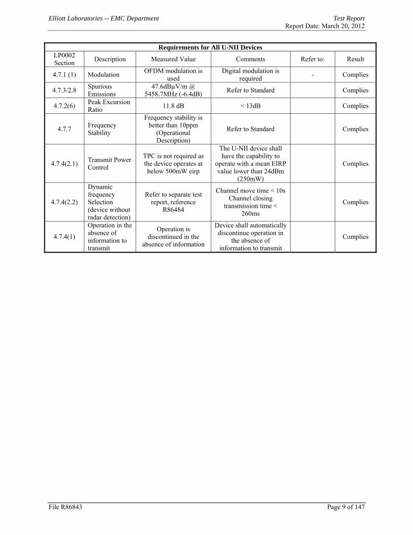
Requirements for All U-NII Devices
LP0002 Section Description Measured Value Comments Refer to: Result
4.7.1 (1) Modulation OFDM modulation is used
Digital modulation is required - Complies
4.7.3/2.8 Spurious Emissions
47.6dBµV/m @ 5458.7MHz (-6.4dB) Refer to Standard Complies
4.7.2(6) Peak Excursion Ratio 11.8 dB < 13dB Complies
4.7.7 Frequency Stability
Frequency stability is better than 10ppm
(Operational Description)
Refer to Standard Complies
4.7.4(2.1) Transmit Power Control
TPC is not required as the device operates at below 500mW eirp
The U-NII device shall have the capability to
operate with a mean EIRP value lower than 24dBm
(250mW)
Complies
4.7.4(2.2)
Dynamic frequency Selection (device without radar detection)
Refer to separate test report, reference
R86484
Channel move time < 10s Channel closing
transmission time < 260ms
Complies
4.7.4(1)
Operation in the absence of information to transmit
Operation is discontinued in the
absence of information
Device shall automatically discontinue operation in
the absence of information to transmit
Complies
Elliott Laboratories -- EMC Department Test Report Report Date: March 20, 2012
File R86843 Page 10 of 147
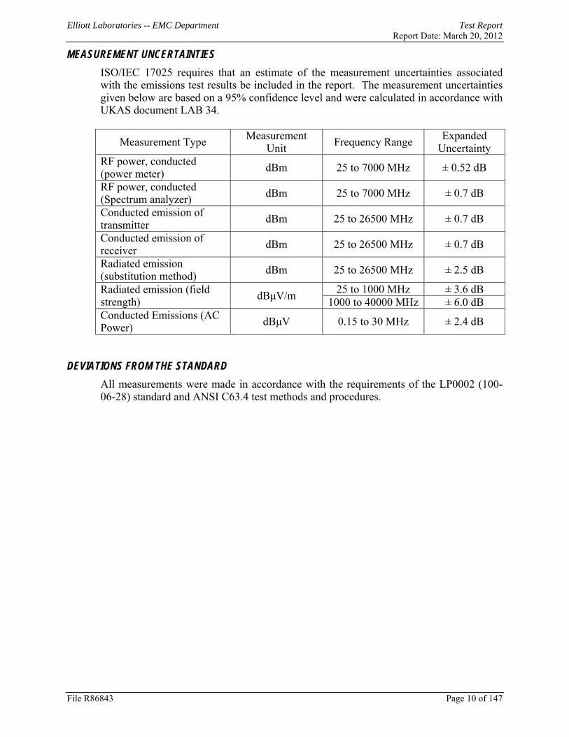
MEASUREMENT UNCERTAINTIES ISO/IEC 17025 requires that an estimate of the measurement uncertainties associated with the emissions test results be included in the report. The measurement uncertainties given below are based on a 95% confidence level and were calculated in accordance with UKAS document LAB 34.
Measurement Type Measurement Unit Frequency Range Expanded
Uncertainty RF power, conducted (power meter) dBm 25 to 7000 MHz ± 0.52 dB
RF power, conducted (Spectrum analyzer) dBm 25 to 7000 MHz ± 0.7 dB
Conducted emission of transmitter dBm 25 to 26500 MHz ± 0.7 dB
Conducted emission of receiver dBm 25 to 26500 MHz ± 0.7 dB
Radiated emission (substitution method) dBm 25 to 26500 MHz ± 2.5 dB
Radiated emission (field strength) dBμV/m 25 to 1000 MHz ± 3.6 dB
1000 to 40000 MHz ± 6.0 dB Conducted Emissions (AC Power) dBμV 0.15 to 30 MHz ± 2.4 dB
DEVIATIONS FROM THE STANDARD
All measurements were made in accordance with the requirements of the LP0002 (100-06-28) standard and ANSI C63.4 test methods and procedures.

Elliott Laboratories -- EMC Department Test Report Report Date: March 20, 2012
File R86843 Page 11 of 147
EQUIPMENT UNDER TEST (EUT) DETAILS GENERAL
The Summit Data Communications model SDC-SSD40NBT is an 802.11abgn 1x1 with Bluetooth 2.1 module. The sample was received on October 19, 2010 and tested on October 19, 20 and 21 and November 19 and 24, 2010 and May 11, August 2, 4, 10, 12, 13, 16, 17, 18 19, 20, 23, 24, 26 and October 6, 7, 19, 20 and 26 and November 3, 4, 7, 8, 9, 15, 2011. The EUT consisted of the following component(s):
Company Model Description Serial Number FCC ID
Summit SDC-SSD40NBT
802.11abgn 1x with BT Prototype TWG-
SDCSSD40NBT OTHER EUT DETAILS
The EUT supports single transmit chain operation. The EUT supports 20MHz operation only. The SSD40NBT Module was tested on a MSD40NBT board.
ANTENNA SYSTEM
Dipole Antenna #1 - 2.4 and 5GHz bands - Larsen, R380.500.314, 1.6dBi (2.4GHz), 5dBi (5GHz) Dipole Antenna #2 - 2.4 GHz only - Cisco Air-Ant 4941 2dBi(2.4GHz) In the 2.4GHz range, the Cisco antenna was tested as they represented the highest gain antennas of each available type. In the 5GHz range, Larsen antenna was tested as the represented the highest gain antennas of each available type. The antenna connects to the EUT via a non-standard u.FL antenna connector, thereby meeting the requirements of FCC 15.203.
ENCLOSURE
The EUT has no enclosure. It is designed to be installed within the enclosure of a host computer.
MODIFICATIONS
No modifications were made to the EUT during the time the product was at Elliott.

Elliott Laboratories -- EMC Department Test Report Report Date: March 20, 2012
File R86843 Page 12 of 147
SUPPORT EQUIPMENT
The following equipment was used as support equipment for testing:
Company Model Description Serial Number FCC ID Delta Electronics EADP-10BB AC/DC Adapter 59A401Z9UP42K N/A
HP iPaQ PDA 2CK702010G N/A
EUT INTERFACE PORTS
The I/O cabling configuration during testing was as follows:
Port Connected To
Cable(s) Description Shielded or Unshielded Length(m)
AC/DC Adapter iPaq 2wire Unshielded 1.5m
AC/DC Adapter AC Mains - - -
EUT OPERATION
During testing, the EUT was configured to transmit continuously at the lowest data rate for the mode as this resulted in the highest output power.
Elliott Laboratories -- EMC Department Test Report Report Date: March 20, 2012
File R86843 Page 13 of 147
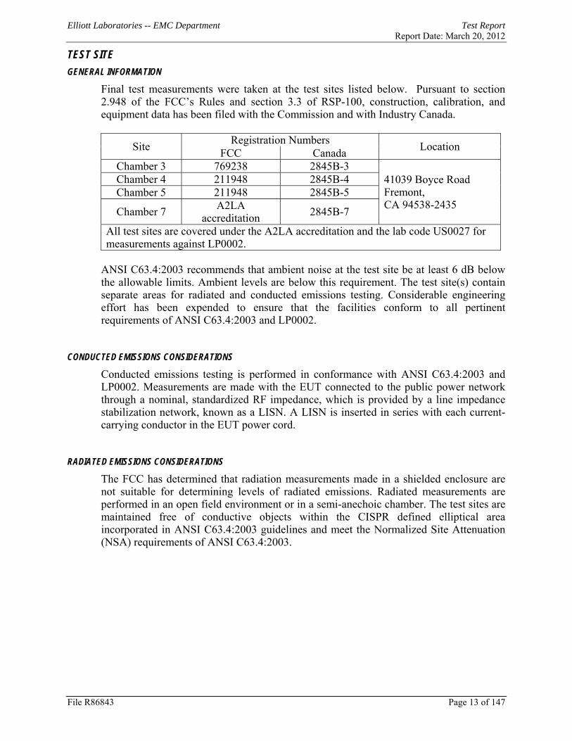
TEST SITE GENERAL INFORMATION
Final test measurements were taken at the test sites listed below. Pursuant to section 2.948 of the FCC’s Rules and section 3.3 of RSP-100, construction, calibration, and equipment data has been filed with the Commission and with Industry Canada.
Site Registration Numbers Location FCC Canada Chamber 3 769238 2845B-3
41039 Boyce Road Fremont, CA 94538-2435
Chamber 4 211948 2845B-4 Chamber 5 211948 2845B-5
Chamber 7 A2LA accreditation 2845B-7
All test sites are covered under the A2LA accreditation and the lab code US0027 for measurements against LP0002.
ANSI C63.4:2003 recommends that ambient noise at the test site be at least 6 dB below the allowable limits. Ambient levels are below this requirement. The test site(s) contain separate areas for radiated and conducted emissions testing. Considerable engineering effort has been expended to ensure that the facilities conform to all pertinent requirements of ANSI C63.4:2003 and LP0002.
CONDUCTED EMISSIONS CONSIDERATIONS
Conducted emissions testing is performed in conformance with ANSI C63.4:2003 and LP0002. Measurements are made with the EUT connected to the public power network through a nominal, standardized RF impedance, which is provided by a line impedance stabilization network, known as a LISN. A LISN is inserted in series with each current-carrying conductor in the EUT power cord.
RADIATED EMISSIONS CONSIDERATIONS
The FCC has determined that radiation measurements made in a shielded enclosure are not suitable for determining levels of radiated emissions. Radiated measurements are performed in an open field environment or in a semi-anechoic chamber. The test sites are maintained free of conductive objects within the CISPR defined elliptical area incorporated in ANSI C63.4:2003 guidelines and meet the Normalized Site Attenuation (NSA) requirements of ANSI C63.4:2003.

Elliott Laboratories -- EMC Department Test Report Report Date: March 20, 2012
File R86843 Page 14 of 147
MEASUREMENT INSTRUMENTATION RECEIVER SYSTEM
An EMI receiver as specified in CISPR 16-1-1 is used for emissions measurements. The receivers used can measure over the frequency range of 9 kHz up to 2000 MHz. These receivers allow both ease of measurement and high accuracy to be achieved. The receivers have Peak, Average, and CISPR (Quasi-peak) detectors built into their design so no external adapters are necessary. The receiver automatically sets the required bandwidth for the CISPR detector used during measurements. If the repetition frequency of the signal being measured is below 20Hz, peak measurements are made in lieu of Quasi-Peak measurements. For measurements above the frequency range of the receivers, a spectrum analyzer is utilized because it provides visibility of the entire spectrum along with the precision and versatility required to support engineering analysis. Average measurements above 1000MHz are performed on the spectrum analyzer using the linear-average method with a resolution bandwidth of 1 MHz and a video bandwidth of 10 Hz, unless the signal is pulsed in which case the average (or video) bandwidth of the measuring instrument is reduced to onset of pulse desensitization and then increased.
INSTRUMENT CONTROL COMPUTER
The receivers utilize either a Rohde & Schwarz EZM Spectrum Monitor/Controller or contain an internal Spectrum Monitor/Controller to view and convert the receiver measurements to the field strength at an antenna or voltage developed at the LISN measurement port, which is then compared directly with the appropriate specification limit. This provides faster, more accurate readings by performing the conversions described under Sample Calculations within the Test Procedures section of this report. Results are printed in a graphic and/or tabular format, as appropriate. A personal computer is used to record all measurements made with the receivers. The Spectrum Monitor provides a visual display of the signal being measured. In addition, the controller or a personal computer run automated data collection programs which control the receivers. This provides added accuracy since all site correction factors, such as cable loss and antenna factors are added automatically.
LINE IMPEDANCE STABILIZATION NETWORK (LISN)
Line conducted measurements utilize a fifty microhenry Line Impedance Stabilization Network as the monitoring point. The LISN used also contains a 250 uH CISPR adapter. This network provides for calibrated radio frequency noise measurements by the design of the internal low pass and high pass filters on the EUT and measurement ports, respectively.
Elliott Laboratories -- EMC Department Test Report Report Date: March 20, 2012
File R86843 Page 15 of 147
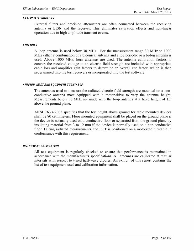
FILTERS/ATTENUATORS
External filters and precision attenuators are often connected between the receiving antenna or LISN and the receiver. This eliminates saturation effects and non-linear operation due to high amplitude transient events.
ANTENNAS
A loop antenna is used below 30 MHz. For the measurement range 30 MHz to 1000 MHz either a combination of a biconical antenna and a log periodic or a bi-log antenna is used. Above 1000 MHz, horn antennas are used. The antenna calibration factors to convert the received voltage to an electric field strength are included with appropriate cable loss and amplifier gain factors to determine an overall site factor, which is then programmed into the test receivers or incorporated into the test software.
ANTENNA MAST AND EQUIPMENT TURNTABLE
The antennas used to measure the radiated electric field strength are mounted on a non-conductive antenna mast equipped with a motor-drive to vary the antenna height. Measurements below 30 MHz are made with the loop antenna at a fixed height of 1m above the ground plane. ANSI C63.4:2003 specifies that the test height above ground for table mounted devices shall be 80 centimeters. Floor mounted equipment shall be placed on the ground plane if the device is normally used on a conductive floor or separated from the ground plane by insulating material from 3 to 12 mm if the device is normally used on a non-conductive floor. During radiated measurements, the EUT is positioned on a motorized turntable in conformance with this requirement.
INSTRUMENT CALIBRATION
All test equipment is regularly checked to ensure that performance is maintained in accordance with the manufacturer's specifications. All antennas are calibrated at regular intervals with respect to tuned half-wave dipoles. An exhibit of this report contains the list of test equipment used and calibration information.

Elliott Laboratories -- EMC Department Test Report Report Date: March 20, 2012
TEST PROCEDURES EUT AND CABLE PLACEMENT
The regulations require that interconnecting cables be connected to the available ports of the unit and that the placement of the unit and the attached cables simulate the worst case orientation that can be expected from a typical installation, so far as practicable. To this end, the position of the unit and associated cabling is varied within the guidelines of ANSI C63.4:2003, and the worst-case orientation is used for final measurements.
CONDUCTED EMISSIONS
Conducted emissions are measured at the plug end of the power cord supplied with the EUT. Excess power cord length is wrapped in a bundle between 30 and 40 centimeters in length near the center of the cord. Preliminary measurements are made to determine the highest amplitude emission relative to the specification limit for all the modes of operation. Placement of system components and varying of cable positions are performed in each mode. A final peak mode scan is then performed in the position and mode for which the highest emission was noted on all current carrying conductors of the power cord.
0.4m
0.8m
LISN AE
LISN EUT
File R86843 Page 16 of 147
Elliott Laboratories -- EMC Department Test Report Report Date: March 20, 2012
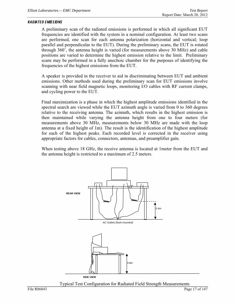
RADIATED EMISSIONS
A preliminary scan of the radiated emissions is performed in which all significant EUT frequencies are identified with the system in a nominal configuration. At least two scans are performed, one scan for each antenna polarization (horizontal and vertical; loop parallel and perpendicular to the EUT). During the preliminary scans, the EUT is rotated through 360˚, the antenna height is varied (for measurements above 30 MHz) and cable positions are varied to determine the highest emission relative to the limit. Preliminary scans may be performed in a fully anechoic chamber for the purposes of identifying the frequencies of the highest emissions from the EUT. A speaker is provided in the receiver to aid in discriminating between EUT and ambient emissions. Other methods used during the preliminary scan for EUT emissions involve scanning with near field magnetic loops, monitoring I/O cables with RF current clamps, and cycling power to the EUT. Final maximization is a phase in which the highest amplitude emissions identified in the spectral search are viewed while the EUT azimuth angle is varied from 0 to 360 degrees relative to the receiving antenna. The azimuth, which results in the highest emission is then maintained while varying the antenna height from one to four meters (for measurements above 30 MHz, measurements below 30 MHz are made with the loop antenna at a fixed height of 1m). The result is the identification of the highest amplitude for each of the highest peaks. Each recorded level is corrected in the receiver using appropriate factors for cables, connectors, antennas, and preamplifier gain. When testing above 18 GHz, the receive antenna is located at 1meter from the EUT and the antenna height is restricted to a maximum of 2.5 meters.
File R86843 Page 17 of 147 Typical Test Configuration for Radiated Field Strength Measurements
AC Outlets (flush-mounted)
SIDE VIEW
REAR VIEW
0.4m
0.8m
Elliott Laboratories -- EMC Department Test Report Report Date: March 20, 2012
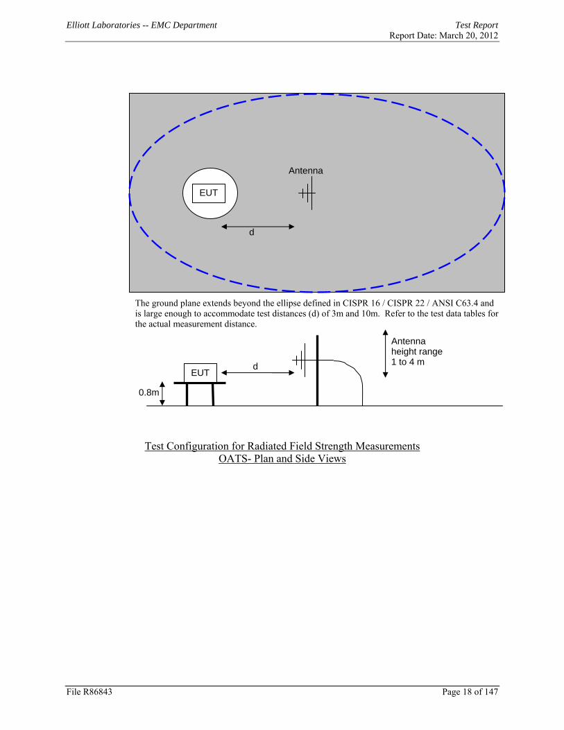
EUT
Antenna
d
The ground plane extends beyond the ellipse defined in CISPR 16 / CISPR 22 / ANSI C63.4 and is large enough to accommodate test distances (d) of 3m and 10m. Refer to the test data tables for the actual measurement distance.
Antenna height range 1 to 4 m d
EUT
0.8m
Test Configuration for Radiated Field Strength Measurements
OATS- Plan and Side Views
File R86843 Page 18 of 147

Elliott Laboratories -- EMC Department Test Report Report Date: March 20, 2012
The anechoic materials on the walls and ceiling ensure compliance with the normalized site attenuation requirements of CISPR 16 / CISPR 22 / ANSI C63.4 for an alternate test site at the measurement distances used. Floor-standing equipment is placed on the floor with insulating supports between the unit and the ground plane.
d
EUT
Antenna
EUT d
0.8m
Antenna height range 1 to 4 m
Test Configuration for Radiated Field Strength Measurements
Semi-Anechoic Chamber, Plan and Side Views
File R86843 Page 19 of 147

Elliott Laboratories -- EMC Department Test Report Report Date: March 20, 2012
CONDUCTED EMISSIONS FROM ANTENNA PORT
Direct measurements of power, bandwidth and power spectral density are performed, where possible, with the antenna port of the EUT connected to either the power meter or spectrum analyzer via a suitable attenuator and/or filter. These are used to ensure that the front end of the measurement instrument is not overloaded by the fundamental transmission.
Attenuator (optional)
Spectrum Analyzer (or
Power Meter) EUT
Test Configuration for Antenna Port Measurements
Measurement bandwidths (video and resolution) are set in accordance with the relevant standards and Elliott’s test procedures for the type of radio being tested. When power measurements are made using a resolution bandwidth less than the signal bandwidth the power is calculated by summing the power across the signal bandwidth using either the analyzer channel power function or by capturing the trace data and calculating the power using software. In both cases the summed power is corrected to account for the equivalent noise bandwidth (ENBW) of the resolution bandwidth used. If power averaging is used (typically for certain digital modulation techniques), the EUT is configured to transmit continuously. Power averaging is performed using either the built-in function of the analyzer or, if the analyzer does not feature power averaging, using external software. In both cases the average power is calculated over a number of sweeps (typically 100). When the EUT cannot be configured to continuously transmit then either the analyzer is configured to perform a gated sweep to ensure that the power is averaged over periods that the device is transmitting or power averaging is disabled and a max-hold feature is used. If a power meter is used to make output power measurements the sensor head type (peak or average) is stated in the test data table.
BANDWIDTH MEASUREMENTS
The 6dB, 20dB and/or 26dB signal bandwidth is measured in using the bandwidths recommended by ANSI C63.4 and LP0002. When required, the 99% bandwidth is measured using the methods detailed in RSS GEN.
File R86843 Page 20 of 147

Elliott Laboratories -- EMC Department Test Report Report Date: March 20, 2012
File R86843 Page 21 of 147
SPECIFICATION LIMITS AND SAMPLE CALCULATIONS
The limits for conducted emissions are given in units of microvolts, and the limits for radiated emissions are given in units of microvolts per meter at a specified test distance. Data is measured in the logarithmic form of decibels relative to one microvolt, or dB microvolts (dBuV). For radiated emissions, the measured data is converted to the field strength at the antenna in dB microvolts per meter (dBuV/m). The results are then converted to the linear forms of uV and uV/m for comparison to published specifications. For reference, converting the specification limits from linear to decibel form is accomplished by taking the base ten logarithm, then multiplying by 20. These limits in both linear and logarithmic form are as follows:
CONDUCTED EMISSIONS SPECIFICATION LIMITS: LP0002 SECTION 2.3
The table below shows the limits for the emissions on the AC power line from an intentional radiator and a receiver.
Frequency (MHz)
Average Limit
(dBuV)
Quasi Peak Limit
(dBuV)
0.150 to 0.500
Linear decrease on logarithmic frequency
axis between 56.0 and 46.0
Linear decrease on logarithmic frequency
axis between 66.0 and 56.0
0.500 to 5.000 46.0 56.0 5.000 to 30.000 50.0 60.0

Elliott Laboratories -- EMC Department Test Report Report Date: March 20, 2012
File R86843 Page 22 of 147
GENERAL RADIATED EMISSIONS SPECIFICATION LIMITS, LP0002 SECTION 2.8
The table below shows the limits for the spurious emissions from transmitters that fall in restricted bands1, the limits for all emissions from a low power device operating under the general rules of LP0002 and the limits for receiver spurious emissions. Note that receivers operating below 30 MHz are exempt from these requirements and receiver spurious limits do not apply below 30MHz.
Frequency
Range (MHz)
Limit (uV/m)
Limit (dBuV/m @ 3m)
0.009-0.490 2400/FKHz @ 300m 67.6-20*log10(FKHz) @ 300m
0.490-1.705 24000/FKHz @ 30m 87.6-20*log10(FKHz) @ 30m
1.705 to 30 30 @ 30m 29.5 @ 30m
30 to 88 100 @ 3m 40 @ 3m
88 to 216 150 @ 3m 43.5 @ 3m
216 to 960 200 @ 3m 46.0 @ 3m
Above 960 500 @ 3m 54.0 @ 3m
OUTPUT POWER LIMITS – DIGITAL TRANSMISSION SYSTEMS (LP0002 3.10.1)
The table below shows the limits for output power and output power density. Where the signal bandwidth is less than 20 MHz the maximum output power is reduced to the power spectral density limit plus 10 times the log of the bandwidth (in MHz).
Operating Frequency (MHz) Output Power Power Spectral Density
902 – 928 1 Watt (30 dBm) 8 dBm/3kHz 2400 – 2483.5 1 Watt (30 dBm) 8 dBm/3kHz 5725 – 5850 1 Watt (30 dBm) 8 dBm/3kHz
The maximum permitted output power is reduced by 1dB for every dB the antenna gain exceeds 6dBi. Fixed point-to-point applications using the 5725 – 5850 MHz band are not subject to this restriction.
TRANSMITTER RADIATED SPURIOUS EMISSIONS LIMITS (LP0002 3.10.1)
The limits for unwanted (spurious) emissions from the transmitter falling in the restricted bands are those specified in section 2.8 of LP0002. All other unwanted (spurious) emissions shall be at least 20dB below the level of the highest in-band signal level (30dB for digitally modulated devices when the average output power is measured rather than peak output power).
1 The restricted bands are detailed in LP0002 section 2.7
Elliott Laboratories -- EMC Department Test Report Report Date: March 20, 2012
File R86843 Page 23 of 147
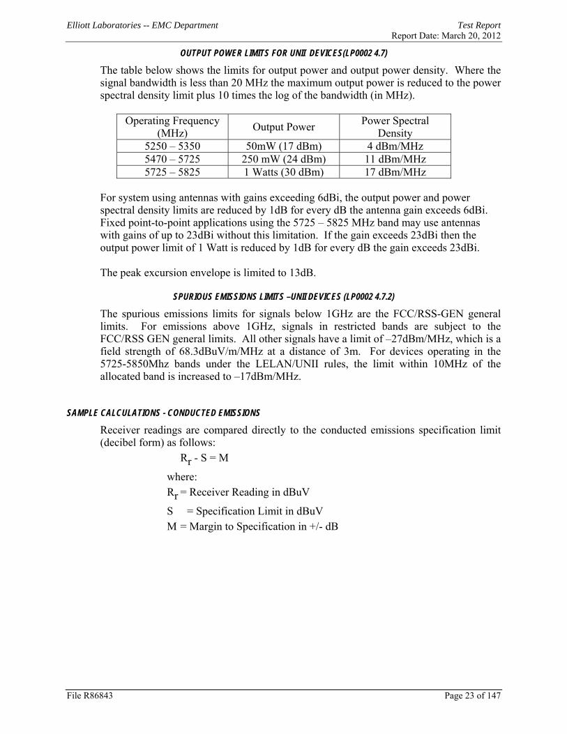
OUTPUT POWER LIMITS FOR UNII DEVICES(LP0002 4.7)
The table below shows the limits for output power and output power density. Where the signal bandwidth is less than 20 MHz the maximum output power is reduced to the power spectral density limit plus 10 times the log of the bandwidth (in MHz).
Operating Frequency (MHz) Output Power Power Spectral
Density 5250 – 5350 50mW (17 dBm) 4 dBm/MHz 5470 – 5725 250 mW (24 dBm) 11 dBm/MHz 5725 – 5825 1 Watts (30 dBm) 17 dBm/MHz
For system using antennas with gains exceeding 6dBi, the output power and power spectral density limits are reduced by 1dB for every dB the antenna gain exceeds 6dBi. Fixed point-to-point applications using the 5725 – 5825 MHz band may use antennas with gains of up to 23dBi without this limitation. If the gain exceeds 23dBi then the output power limit of 1 Watt is reduced by 1dB for every dB the gain exceeds 23dBi. The peak excursion envelope is limited to 13dB.
SPURIOUS EMISSIONS LIMITS –UNII DEVICES (LP0002 4.7.2)
The spurious emissions limits for signals below 1GHz are the FCC/RSS-GEN general limits. For emissions above 1GHz, signals in restricted bands are subject to the FCC/RSS GEN general limits. All other signals have a limit of –27dBm/MHz, which is a field strength of 68.3dBuV/m/MHz at a distance of 3m. For devices operating in the 5725-5850Mhz bands under the LELAN/UNII rules, the limit within 10MHz of the allocated band is increased to –17dBm/MHz.
SAMPLE CALCULATIONS - CONDUCTED EMISSIONS
Receiver readings are compared directly to the conducted emissions specification limit (decibel form) as follows: Rr - S = M
where: Rr = Receiver Reading in dBuV
S = Specification Limit in dBuV M = Margin to Specification in +/- dB

Elliott Laboratories -- EMC Department Test Report Report Date: March 20, 2012
File R86843 Page 24 of 147
SAMPLE CALCULATIONS - RADIATED EMISSIONS
Receiver readings are compared directly to the specification limit (decibel form). The receiver internally corrects for cable loss, preamplifier gain, and antenna factor. The calculations are in the reverse direction of the actual signal flow, thus cable loss is added and the amplifier gain is subtracted. The Antenna Factor converts the voltage at the antenna coaxial connector to the field strength at the antenna elements. A distance factor, when used for electric field measurements above 30MHz, is calculated by using the following formula: Fd = 20*LOG10 (Dm/Ds) where: Fd = Distance Factor in dB Dm = Measurement Distance in meters Ds = Specification Distance in meters
For electric field measurements below 30MHz the extrapolation factor is either determined by making measurements at multiple distances or a theoretical value is calculated using the formula:
Fd = 40*LOG10 (Dm/Ds)
Measurement Distance is the distance at which the measurements were taken and Specification Distance is the distance at which the specification limits are based. The antenna factor converts the voltage at the antenna coaxial connector to the field strength at the antenna elements. The margin of a given emission peak relative to the limit is calculated as follows:
Rc = Rr + Fd and M = Rc - Ls where: Rr = Receiver Reading in dBuV/m Fd = Distance Factor in dB Rc = Corrected Reading in dBuV/m Ls = Specification Limit in dBuV/m M = Margin in dB Relative to Spec

Elliott Laboratories -- EMC Department Test Report Report Date: March 20, 2012
File R86843 Page 25 of 147
SAMPLE CALCULATIONS - FIELD STRENGTH TO EIRP CONVERSION
Where the radiated electric field strength is expressed in terms of the equivalent isotropic radiated power (eirp), or where a field strength measurement of output power is made in lieu of a direct measurement, the following formula is used to convert between eirp and field strength at a distance of d (meters) from the equipment under test: E = 1000000 √ 30 P microvolts per meter d
where P is the eirp (Watts) For a measurement at 3m the conversion from a logarithmic value for field strength (dBuV/m) to an eirp power (dBm) is -95.3dB.

Elliott Laboratories -- EMC Department Test Report Report Date: March 20, 2012
File R86843 Page 26 of 147
APPENDIX A TEST EQUIPMENT CALIBRATION DATA T83195 Radiated Emissions, 1000 - 26,500 MHz, 19-Oct-10 Manufacturer Description Model Asset # Cal Due
Hewlett Packard Microwave Preamplifier, 1-26.5GHz
8449B 785 5/26/2011
EMCO Antenna, Horn, 1-18 GHz 3115 786 12/11/2011Hewlett Packard SpecAn 30 Hz -40 GHz, SV
(SA40) Red 8564E (84125C) 1148 7/12/2011
TX Spurious Emissions, 20-Oct-10 Manufacturer Description Model Asset # Cal Due
Hewlett Packard Microwave Preamplifier, 1-26.5GHz
8449B 785 5/26/2011
EMCO Antenna, Horn, 1-18 GHz 3115 786 12/11/2011Hewlett Packard Head (Inc W1-W4, 1143, 2198)
Red 84125C 1145 1/13/2011
Hewlett Packard SpecAn 30 Hz -40 GHz, SV (SA40) Red
8564E (84125C) 1148 7/12/2011
A.H. Systems Spare System Horn, 18-40GHz SAS-574, p/n: 2581 2162 1/19/2011 Micro-Tronics Band Reject Filter, 2400-2500
MHz BRM50702-02 2249 10/11/2011
Radio (Radiated BE), 21-Oct-10 Manufacturer Description Model Asset # Cal Due
EMCO Antenna, Horn, 1-18GHz 3115 868 6/8/2012 Rohde & Schwarz Power Meter, Single Channel NRVS 1422 11/10/2010Rohde & Schwarz Power Sensor 100 uW - 10
Watts NRV-Z53 1555 2/5/2011
Rohde & Schwarz Attenuator, 20 dB , 50 ohm, 10W, DC-18 GHz
20dB, 10W, Type N 1556 2/5/2011
Hewlett Packard SpecAn 9 kHz - 40 GHz, (SA40) Purple
8564E (84125C) 1771 8/26/2011
Radiated Emissions, 1000 - 26,500 MHz, 11-May-11 Manufacturer Description Model Asset # Cal Due
Hewlett Packard Microwave Preamplifier, 1-26.5GHz
8449B 785 5/26/2011
EMCO Antenna, Horn, 1-18 GHz (SA40-Blu)
3115 1386 9/21/2012
Hewlett Packard SpecAn 9 kHz - 40 GHz, FT (SA40) Blue
8564E (84125C) 1393 5/14/2011
Hewlett Packard Head (Inc W1-W4, 1742 , 1743) Blue
84125C 1620 5/9/2012
A.H. Systems Blue System Horn, 18-40GHz SAS-574, p/n: 2581 2159 3/23/2012 Micro-Tronics Band Reject Filter, 2400-2500
MHz BRM50702-02 2249 10/11/2011
Radiated Emissions, 1000 - 26,500 MHz, 14-May-11 Manufacturer Description Model Asset # Cal Due
Hewlett Packard Microwave Preamplifier, 1-26.5GHz
8449B 785 5/26/2011
EMCO Antenna, Horn, 1-18GHz 3115 868 6/8/2012 Hewlett Packard SpecAn 9 kHz - 40 GHz, FT
(SA40) Blue 8564E (84125C) 1393 5/14/2011
Hewlett Packard Head (Inc W1-W4, 1742 , 1743) Blue
84125C 1620 5/9/2012
A.H. Systems Blue System Horn, 18-40GHz SAS-574, p/n: 2581 2159 3/23/2012

Elliott Laboratories -- EMC Department Test Report Report Date: March 20, 2012
File R86843 Page 27 of 147
Micro-Tronics Band Reject Filter, 2400-2500 MHz
BRM50702-02 2238 10/1/2011
Radiated Emissions, 1000 - 26,500 MHz, 17-May-11 Manufacturer Description Model Asset # Cal Due
Hewlett Packard Microwave Preamplifier, 1-26.5GHz
8449B 263 12/8/2011
EMCO Antenna, Horn, 1-18GHz 3115 868 6/8/2012 Hewlett Packard Head (Inc flex cable, 1143,
2198) Red 84125C 1145 2/17/2012
Hewlett Packard SpecAn 30 Hz -40 GHz, SV (SA40) Red
8564E (84125C) 1148 7/12/2011
A.H. Systems Purple System Horn, 18-40GHz SAS-574, p/n: 2581 2160 2/9/2012 Micro-Tronics Band Reject Filter, 2400-2500
MHz BRM50702-02 2238 10/1/2011
Radiated Emissions, 1000 - 40,000 MHz, 18-May-11 Manufacturer Description Model Asset # Cal Due
Hewlett Packard Microwave Preamplifier, 1-26.5GHz
8449B 785 5/26/2011
EMCO Antenna, Horn, 1-18 GHz (SA40-Blu)
3115 1386 9/21/2012
Hewlett Packard SpecAn 9 kHz - 40 GHz, FT (SA40) Blue
8564E (84125C) 1393 6/14/2011
Hewlett Packard Head (Inc W1-W4, 1742 , 1743) Blue
84125C 1620 5/9/2012
Micro-Tronics Band Reject Filter, 5725-5875 MHz
BRC50705-02 1682 3/23/2012
A.H. Systems Blue System Horn, 18-40GHz SAS-574, p/n: 2581 2159 3/23/2012 Micro-Tronics Band Reject Filter, 2400-2500
MHz BRM50702-02 2238 10/1/2011
Radiated Emissions, 1000 - 6,500 MHz, 19-May-11 Manufacturer Description Model Asset # Cal Due
EMCO Antenna, Horn, 1-18 GHz (SA40-Blu)
3115 1386 9/21/2012
Hewlett Packard SpecAn 9 kHz - 40 GHz, FT (SA40) Blue
8564E (84125C) 1393 6/14/2011
Radiated Emissions, 1000 - 18,000 MHz, 20-May-11 Manufacturer Description Model Asset # Cal Due
Hewlett Packard Microwave Preamplifier, 1-26.5GHz
8449B 263 12/8/2011
Hewlett Packard SpecAn 30 Hz -40 GHz, SV (SA40) Red
8564E (84125C) 1148 7/12/2011
EMCO Antenna, Horn, 1-18 GHz 3115 1561 6/22/2012 Micro-Tronics Band Reject Filter, 2400-2500
MHz BRM50702-02 2238 10/1/2011
Radio Antenna Port (Power and Spurious Emissions), 20-May-11 Manufacturer Description Model Asset # Cal Due
Hewlett Packard SpecAn 30 Hz -40 GHz, SV (SA40) Red
8564E (84125C) 1148 7/12/2011
Rohde & Schwarz Power Meter, Single Channel, +1795+1796
NRVS 1534 5/17/2012
Rohde & Schwarz
Power Sensor 100 uW - 2 Watts (w/ 20 dB pad, SN BJ5155)
NRV-Z32 1536 9/13/2011
Rohde & Schwarz Power Sensor, 1 uW-100 mW, DC-18 GHz, 50ohms
NRV-Z51 2152 11/6/2011
Elliott Laboratories -- EMC Department Test Report Report Date: March 20, 2012
File R86843 Page 28 of 147
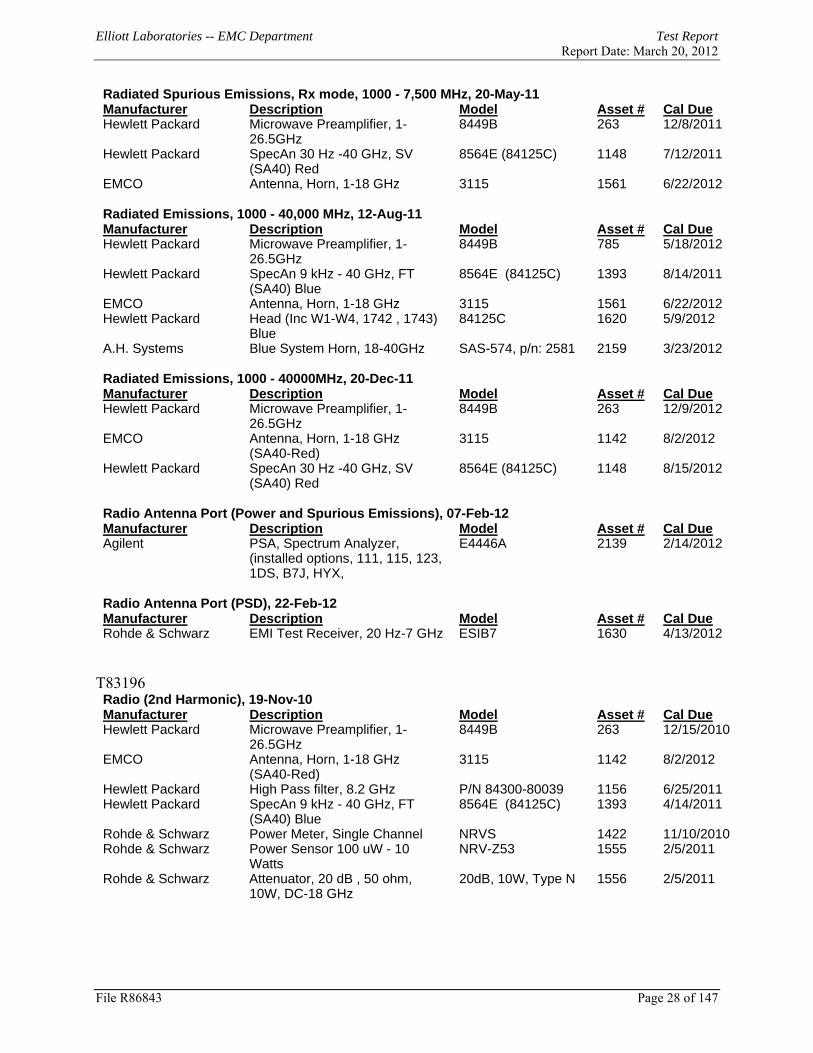
Radiated Spurious Emissions, Rx mode, 1000 - 7,500 MHz, 20-May-11 Manufacturer Description Model Asset # Cal Due
Hewlett Packard Microwave Preamplifier, 1-26.5GHz
8449B 263 12/8/2011
Hewlett Packard SpecAn 30 Hz -40 GHz, SV (SA40) Red
8564E (84125C) 1148 7/12/2011
EMCO Antenna, Horn, 1-18 GHz 3115 1561 6/22/2012 Radiated Emissions, 1000 - 40,000 MHz, 12-Aug-11 Manufacturer Description Model Asset # Cal Due
Hewlett Packard Microwave Preamplifier, 1-26.5GHz
8449B 785 5/18/2012
Hewlett Packard SpecAn 9 kHz - 40 GHz, FT (SA40) Blue
8564E (84125C) 1393 8/14/2011
EMCO Antenna, Horn, 1-18 GHz 3115 1561 6/22/2012 Hewlett Packard Head (Inc W1-W4, 1742 , 1743)
Blue 84125C 1620 5/9/2012
A.H. Systems Blue System Horn, 18-40GHz SAS-574, p/n: 2581 2159 3/23/2012 Radiated Emissions, 1000 - 40000MHz, 20-Dec-11 Manufacturer Description Model Asset # Cal Due
Hewlett Packard Microwave Preamplifier, 1-26.5GHz
8449B 263 12/9/2012
EMCO Antenna, Horn, 1-18 GHz (SA40-Red)
3115 1142 8/2/2012
Hewlett Packard SpecAn 30 Hz -40 GHz, SV (SA40) Red
8564E (84125C) 1148 8/15/2012
Radio Antenna Port (Power and Spurious Emissions), 07-Feb-12 Manufacturer Description Model Asset # Cal Due
Agilent PSA, Spectrum Analyzer, (installed options, 111, 115, 123, 1DS, B7J, HYX,
E4446A 2139 2/14/2012
Radio Antenna Port (PSD), 22-Feb-12 Manufacturer Description Model Asset # Cal Due
Rohde & Schwarz EMI Test Receiver, 20 Hz-7 GHz ESIB7 1630 4/13/2012
T83196 Radio (2nd Harmonic), 19-Nov-10 Manufacturer Description Model Asset # Cal Due
Hewlett Packard Microwave Preamplifier, 1-26.5GHz
8449B 263 12/15/2010
EMCO Antenna, Horn, 1-18 GHz (SA40-Red)
3115 1142 8/2/2012
Hewlett Packard High Pass filter, 8.2 GHz P/N 84300-80039 1156 6/25/2011 Hewlett Packard SpecAn 9 kHz - 40 GHz, FT
(SA40) Blue 8564E (84125C) 1393 4/14/2011
Rohde & Schwarz Power Meter, Single Channel NRVS 1422 11/10/2010Rohde & Schwarz Power Sensor 100 uW - 10
Watts NRV-Z53 1555 2/5/2011
Rohde & Schwarz Attenuator, 20 dB , 50 ohm, 10W, DC-18 GHz
20dB, 10W, Type N 1556 2/5/2011

Elliott Laboratories -- EMC Department Test Report Report Date: March 20, 2012
File R86843 Page 29 of 147
Radio Antenna Port (Power and Spurious Emissions), 24-Nov-10 Manufacturer Description Model Asset # Cal Due
Hewlett Packard SpecAn 9 kHz - 40 GHz, FT (SA40) Blue
8564E (84125C) 1393 4/14/2011
Rohde & Schwarz Power Sensor 100 uW - 10 Watts
NRV-Z53 1555 2/5/2011
Rohde & Schwarz Attenuator, 20 dB , 50 ohm, 10W, DC-18 GHz
20dB, 10W, Type N 1556 2/5/2011
Rohde & Schwarz Power Meter, Dual Channel NRVD 1787 12/4/2010 Radiated Emissions, 1000 - 18,000 MHz, 04-Aug-11 Manufacturer Description Model Asset # Cal Due
Hewlett Packard Microwave Preamplifier, 1-26.5GHz
8449B 263 12/8/2011
EMCO Antenna, Horn, 1-18 GHz (SA40-Red)
3115 1142 8/2/2012
Hewlett Packard SpecAn 30 Hz -40 GHz, SV (SA40) Red
8564E (84125C) 1148 8/12/2011
Micro-Tronics Band Reject Filter, 5150-5350 MHz
BRC50703-02 2251 10/21/2011
Radiated Emissions, 30 - 40,000 MHz, 12-Aug-11 Manufacturer Description Model Asset # Cal Due
Hewlett Packard Microwave Preamplifier, 1-26.5GHz
8449B 263 12/8/2011
Narda West High Pass Filter, 8 GHz HPF 180 821 3/23/2012 EMCO Antenna, Horn, 1-18 GHz
(SA40-Blu) 3115 1386 9/21/2012
Micro-Tronics Band Reject Filter, 5470-5725 MHz
BRC50704-02 1730 8/5/2012
Hewlett Packard SpecAn 9 kHz - 40 GHz, (SA40) Purple
8564E (84125C) 2415 7/28/2012
Radiated Emissions, 1000 - 40,000 MHz, 13-Aug-11 Manufacturer Description Model Asset # Cal Due
Hewlett Packard Microwave Preamplifier, 1-26.5GHz
8449B 263 12/8/2011
Narda West High Pass Filter, 8 GHz HPF 180 821 3/23/2012 Hewlett Packard Head (Inc flex cable, 1143,
2198) Red 84125C 1145 2/17/2012
EMCO Antenna, Horn, 1-18 GHz (SA40-Blu)
3115 1386 9/21/2012
Micro-Tronics Band Reject Filter, 5470-5725 MHz
BRC50704-02 1730 8/5/2012
A.H. Systems Purple System Horn, 18-40GHz SAS-574, p/n: 2581 2160 2/9/2012 Hewlett Packard SpecAn 9 kHz - 40 GHz, (SA40)
Purple 8564E (84125C) 2415 7/28/2012
Radiated Emissions, 1000 - 40,000 MHz, 16-Aug-11 Manufacturer Description Model Asset # Cal Due
Hewlett Packard Microwave Preamplifier, 1-26.5GHz
8449B 263 12/8/2011
Hewlett Packard Head (Inc flex cable, 1143, 2198) Red
84125C 1145 2/17/2012
EMCO Antenna, Horn, 1-18 GHz (SA40-Blu)
3115 1386 9/21/2012
Micro-Tronics Band Reject Filter, 5470-5725 MHz
BRC50704-02 1681 5/3/2012
A.H. Systems Purple System Horn, 18-40GHz SAS-574, p/n: 2581 2160 2/9/2012
Elliott Laboratories -- EMC Department Test Report Report Date: March 20, 2012
File R86843 Page 30 of 147
Micro-Tronics Band Reject Filter, 5150-5350 MHz
BRC50703-02 2251 10/21/2011
Hewlett Packard SpecAn 9 kHz - 40 GHz, (SA40) Purple
8564E (84125C) 2415 7/28/2012
Radiated Emissions, 1000 - 18,000 MHz, 17-Aug-11 Manufacturer Description Model Asset # Cal Due
Hewlett Packard Microwave Preamplifier, 1-26.5GHz
8449B 263 12/8/2011
Narda West High Pass Filter, 8 GHz HPF 180 821 3/23/2012 EMCO Antenna, Horn, 1-18 GHz
(SA40-Blu) 3115 1386 9/21/2012
Micro-Tronics Band Reject Filter, 5150-5350 MHz
BRC50703-02 2239 10/1/2011
Hewlett Packard SpecAn 9 kHz - 40 GHz, (SA40) Purple
8564E (84125C) 2415 7/28/2012
Radiated Emissions, 1000 - 18,000 MHz, 18-Aug-11 Manufacturer Description Model Asset # Cal Due
Hewlett Packard Microwave Preamplifier, 1-26.5GHz
8449B 263 12/8/2011
EMCO Antenna, Horn, 1-18 GHz (SA40-Blu)
3115 1386 9/21/2012
Micro-Tronics Band Reject Filter, 5150-5350 MHz
BRC50703-02 2239 10/1/2011
Micro-Tronics Band Reject Filter, 5470-5725 MHz
BRC50704-02 2240 10/1/2011
Hewlett Packard SpecAn 9 kHz - 40 GHz, (SA40) Purple
8564E (84125C) 2415 7/28/2012
Radio Antenna Port (Power and Spurious Emissions), 24-Aug-11 Manufacturer Description Model Asset # Cal Due
Hewlett Packard SpecAn 9 kHz - 40 GHz, FT (SA40) Blue
8564E (84125C) 1393 8/9/2012
Rohde & Schwarz EMI Test Receiver, 20 Hz-7 GHz ESIB7 1538 11/2/2011 Radio Antenna Port (Power and Spurious Emissions), 26-Aug-11 Manufacturer Description Model Asset # Cal Due
Hewlett Packard SpecAn 30 Hz -40 GHz, SV (SA40) Red
8564E (84125C) 1148 8/15/2012
Rohde & Schwarz EMI Test Receiver, 20 Hz-7 GHz ESIB7 1756 4/6/2012 Radiated Emissions, 1000 - 18,000 MHz, 15-Nov-11 Manufacturer Description Model Asset # Cal Due
Hewlett Packard Microwave Preamplifier, 1-26.5GHz
8449B 263 12/8/2011
Hewlett Packard SpecAn 30 Hz -40 GHz, SV (SA40) Red
8564E (84125C) 1148 8/15/2012
EMCO Antenna, Horn, 1-18 GHz 3115 1561 6/22/2012 Micro-Tronics Band Reject Filter, 5725-5875
MHz BRC50705-02 1682 3/23/2012
Radiated Emissions, 1000 - 18,000 MHz, 28-Dec-11 Manufacturer Description Model Asset # Cal Due
EMCO Antenna, Horn, 1-18 GHz (SA40-Blu)
3115 1386 9/21/2012
Hewlett Packard Microwave Preamplifier, 1-26.5GHz
8449B 2199 2/23/2012
Hewlett Packard SpecAn 9 kHz - 40 GHz, (SA40) Purple
8564E (84125C) 2415 7/28/2012

Elliott Laboratories -- EMC Department Test Report Report Date: March 20, 2012
File R86843 Page 31 of 147
Radiated Emissions, 1000 - 18,000 MHz, 29-Dec-11 Manufacturer Description Model Asset # Cal Due
Hewlett Packard Microwave Preamplifier, 1-26.5GHz
8449B 263 12/9/2012
Hewlett Packard SpecAn 30 Hz -40 GHz, SV (SA40) Red
8564E (84125C) 1148 8/15/2012
EMCO Antenna, Horn, 1-18 GHz 3115 1561 6/22/2012 Micro-Tronics Band Reject Filter, 5150-5350
MHz BRC50703-02 2239 10/4/2012
Radiated Emissions, 1000 - 18,000 MHz, 30-Dec-11 Manufacturer Description Model Asset # Cal Due
Hewlett Packard Microwave Preamplifier, 1-26.5GHz
8449B 263 12/9/2012
Hewlett Packard SpecAn 30 Hz -40 GHz, SV (SA40) Red
8564E (84125C) 1148 8/15/2012
EMCO Antenna, Horn, 1-18 GHz 3115 1561 6/22/2012 Micro-Tronics Band Reject Filter, 5470-5725
MHz BRC50704-02 1681 9/8/2012
Micro-Tronics Band Reject Filter, 5150-5350 MHz
BRC50703-02 2239 10/4/2012
Radiated Emissions, 1000 - 18,000 MHz, 04-Jan-12 Manufacturer Description Model Asset # Cal Due
EMCO Antenna, Horn, 1-18 GHz (SA40-Blu)
3115 1386 9/21/2012
Micro-Tronics Band Reject Filter, 5150-5350 MHz
BRC50703-02 1729 8/5/2012
Hewlett Packard Microwave Preamplifier, 1-26.5GHz
8449B 2199 2/23/2012
Hewlett Packard SpecAn 9 kHz - 40 GHz, (SA40) Purple
8564E (84125C) 2415 7/28/2012
Radiated Emissions, 1000 - 18,000 MHz, 05-Jan-12 Manufacturer Description Model Asset # Cal Due
EMCO Antenna, Horn, 1-18 GHz (SA40-Blu)
3115 1386 9/21/2012
Micro-Tronics Band Reject Filter, 5150-5350 MHz
BRC50703-02 1729 8/5/2012
Micro-Tronics Band Reject Filter, 5470-5725 MHz
BRC50704-02 1730 8/5/2012
Hewlett Packard Microwave Preamplifier, 1-26.5GHz
8449B 2199 2/23/2012
Hewlett Packard SpecAn 9 kHz - 40 GHz, (SA40) Purple
8564E (84125C) 2415 7/28/2012
Radiated Emissions, 1000 - 40000MHz, 06-Jan-12 Manufacturer Description Model Asset # Cal Due
Hewlett Packard Microwave Preamplifier, 1-26.5GHz
8449B 263 12/9/2012
Hewlett Packard Head (Inc flex cable, 1143, 2198) Red
84125C 1145 2/17/2012
Hewlett Packard SpecAn 30 Hz -40 GHz, SV (SA40) Red
8564E (84125C) 1148 8/15/2012
EMCO Antenna, Horn, 1-18 GHz (SA40-Blu)
3115 1386 9/21/2012
Micro-Tronics Band Reject Filter, 5150-5350 MHz
BRC50703-02 2239 10/4/2012

Elliott Laboratories -- EMC Department Test Report Report Date: March 20, 2012
File R86843 Page 32 of 147
Radio Antenna Port, UNII Power , 23-Jan-12 Manufacturer Description Model Asset # Cal Due
Rohde & Schwarz EMI Test Receiver, 20 Hz-40 GHz
ESIB40 (1088.7490.40)
2493 12/9/2012
Radio Antenna Port (BW), 22-Feb-12 Manufacturer Description Model Asset # Cal Due
Rohde & Schwarz EMI Test Receiver, 20 Hz-7 GHz ESIB7 1630 4/13/2012
T83198 Conducted Emissions - AC Power Ports, 16-Dec-11 Manufacturer Description Model Asset # Cal Due
EMCO LISN, 10 kHz-100 MHz, 25A 3825/2 1292 3/1/2012 Rohde & Schwarz EMI Test Receiver, 20 Hz-7 GHz ESIB7 1756 4/6/2012

Elliott Laboratories -- EMC Department Test Report Report Date: March 20, 2012
File R86843 Page 33 of 147
APPENDIX B TEST DATA LOG SHEETS
T83195 Pages 34 – 94 T83196 Pages 95 –131 T83198 Pages 132 - 140

EMC Test Data
SDC-MSD40NBT (1x1 802.11abg + BT 2.1)
Ron Seide
EMC Test DataFor The
Summit Data CommunicationsModel
Immunity Standard(s): - Environment:
Christine KrebillAccount Manager:
Client: Summit Data Communications Job Number: J78403SDC-MSD40NBT (1x1 802.11abg + BT 2.1) T-Log Number: T83195Model:
-Emissions Standard(s): FCC 15.247/RSS-210 Class: -
Contact: -
Date of Last Test:
R86843 Cover Page 34

EMC Test DataClient:
Contact:Standard:
Summary of Results - Device Operating in the 2400-2483.5 MHz BandSCU:
Run # Mode Channel Antenna Power Setting
#1 2412MHz Cisco -
#11 2462MHz Cisco -
#1 2412MHz Cisco -
#11 2462MHz Cisco -
#1 2412MHz Cisco -
#11 2462MHz Cisco -
Summit Data Communications Job Number: J78403
Model: SDC-MSD40NBT (1x1 802.11abg + BT 2.1)T-Log Number: T83195
Account Manager: Christine Krebill
FCC 15.247/RSS-210 Class: N/ARon Seide
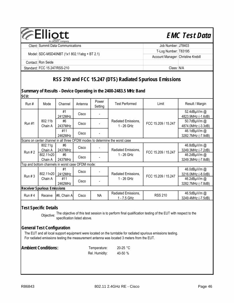
RSS 210 and FCC 15.247 (DTS) Radiated Spurious Emissions
Test Performed
802.11bChain A
Restricted Band Edge at 2390 MHz 15.209
Restricted Band Edge at 2483.5 MHz
Limit Result / Margin
15.209 46.2dBµV/m @ 2497.9MHz (-7.8dB)
Run # 3 802.11n20Chain A
Restricted Band Edge at 2390 MHz 15.209
47.0dBµV/m @ 2381.6MHz (-7.0dB)Run #1
53.2dBµV/m @ 2389.9MHz (-0.8dB)
Restricted Band Edge at 2483.5 MHz 15.209 50.5dBµV/m @
2483.5MHz (-3.5dB)
Run # 2 802.11gChain A
Restricted Band Edge at 2390 MHz 15.209
53.3dBµV/m @ 2389.7MHz (-0.7dB)
Restricted Band Edge at 2483.5 MHz 15.209 50.9dBµV/m @
2483.5MHz (-3.1dB)
Test Specific Details
General Test Configuration
Ambient Conditions: Temperature: 20-25 °CRel. Humidity: 40-50 %
Modifications Made During TestingNo modifications were made to the EUT during testing
Objective: The objective of this test session is to perform final qualification testing of the EUT with respect to the specification listed above.
The EUT and all local support equipment were located on the turntable for radiated spurious emissions testing.For radiated emissions testing the measurement antenna was located 3 meters from the EUT.
Deviations From The StandardNo deviations were made from the requirements of the standard.
R86843 802.11 2.4GHz BE - Cisco Page 35

EMC Test DataClient:
Contact:Standard:
Summit Data Communications Job Number: J78403
Model: SDC-MSD40NBT (1x1 802.11abg + BT 2.1)T-Log Number: T83195
Account Manager: Christine Krebill
FCC 15.247/RSS-210 Class: N/ARon Seide
Run #1, Band Edge Field Strength - 802.11b, Chain A
Run #1a, EUT on Channel #1 2412MHz - 802.11b, Chain A
2390 MHz Band Edge Signal Field StrengthFrequency Level Pol Detector Azimuth Height Comments
MHz dBμV/m v/h Limit Margin Pk/QP/Avg degrees meters2381.600 47.0 V 54.0 -7.0 AVG 0 1.0 RB 1 MHz;VB 10 Hz;Pk2382.600 56.8 V 74.0 -17.2 PK 0 1.0 RB 1 MHz;VB 3 MHz;Pk2378.470 44.7 H 54.0 -9.3 AVG 112 1.9 RB 1 MHz;VB 10 Hz;Pk2386.730 56.2 H 74.0 -17.8 PK 112 1.9 RB 1 MHz;VB 3 MHz;Pk
Config Change: NoneDate of Test: 5/18/2011 Test Location: FT Chamber #7
15.209 / 15.247
Test Engineer: Rafael Varelas
R86843 802.11 2.4GHz BE - Cisco Page 36

EMC Test DataClient:
Contact:Standard:
Summit Data Communications Job Number: J78403
Model: SDC-MSD40NBT (1x1 802.11abg + BT 2.1)T-Log Number: T83195
Account Manager: Christine Krebill
FCC 15.247/RSS-210 Class: N/ARon Seide
R86843 802.11 2.4GHz BE - Cisco Page 37
EMC Test DataClient:
Contact:Standard:
Summit Data Communications Job Number: J78403
Model: SDC-MSD40NBT (1x1 802.11abg + BT 2.1)T-Log Number: T83195
Account Manager: Christine Krebill
FCC 15.247/RSS-210 Class: N/ARon Seide
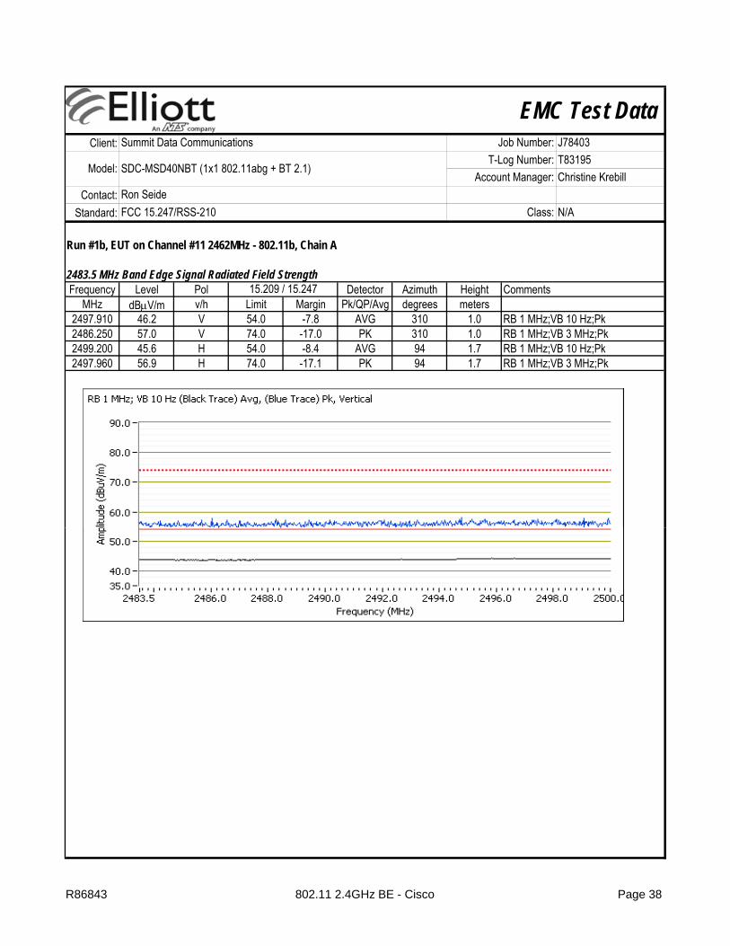
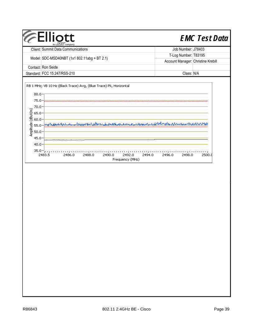
Run #1b, EUT on Channel #11 2462MHz - 802.11b, Chain A
2483.5 MHz Band Edge Signal Radiated Field Strength Frequency Level Pol Detector Azimuth Height Comments
MHz dBμV/m v/h Limit Margin Pk/QP/Avg degrees meters2497.910 46.2 V 54.0 -7.8 AVG 310 1.0 RB 1 MHz;VB 10 Hz;Pk2486.250 57.0 V 74.0 -17.0 PK 310 1.0 RB 1 MHz;VB 3 MHz;Pk2499.200 45.6 H 54.0 -8.4 AVG 94 1.7 RB 1 MHz;VB 10 Hz;Pk2497.960 56.9 H 74.0 -17.1 PK 94 1.7 RB 1 MHz;VB 3 MHz;Pk
15.209 / 15.247
R86843 802.11 2.4GHz BE - Cisco Page 38
EMC Test DataClient:
Contact:Standard:
Summit Data Communications Job Number: J78403
Model: SDC-MSD40NBT (1x1 802.11abg + BT 2.1)T-Log Number: T83195
Account Manager: Christine Krebill
FCC 15.247/RSS-210 Class: N/ARon Seide
R86843 802.11 2.4GHz BE - Cisco Page 39

EMC Test DataClient:
Contact:Standard:
Summit Data Communications Job Number: J78403
Model: SDC-MSD40NBT (1x1 802.11abg + BT 2.1)T-Log Number: T83195
Account Manager: Christine Krebill
FCC 15.247/RSS-210 Class: N/ARon Seide
Run # 2, Band Edge Field Strength - 802.11g, Chain A
Run # 2a, EUT on Channel #1 2412MHz - 802.11g, Chain A
2390 MHz Band Edge Signal Field StrengthFrequency Level Pol Detector Azimuth Height Comments
MHz dBμV/m v/h Limit Margin Pk/QP/Avg degrees meters2389.870 53.2 V 54.0 -0.8 AVG 6 1.3 RB 1 MHz;VB 10 Hz;Pk, 97%2389.930 65.9 V 74.0 -8.1 PK 6 1.3 RB 1 MHz;VB 3 MHz;Pk, 97%2390.000 48.4 H 54.0 -5.6 AVG 179 1.2 RB 1 MHz;VB 10 Hz;Pk, 97%2389.470 59.4 H 74.0 -14.6 PK 179 1.2 RB 1 MHz;VB 3 MHz;Pk, 97%
Config Change: NoneDate of Test: 12/16/2011 Test Location: FT Chamber #4
Test Engineer: Rafael Varelas
15.209 / 15.247
R86843 802.11 2.4GHz BE - Cisco Page 40

EMC Test DataClient:
Contact:Standard:
Summit Data Communications Job Number: J78403
Model: SDC-MSD40NBT (1x1 802.11abg + BT 2.1)T-Log Number: T83195
Account Manager: Christine Krebill
FCC 15.247/RSS-210 Class: N/ARon Seide
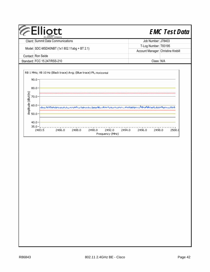
Run # 2b, EUT on Channel #11 2462MHz - 802.11g, Chain A
2483.5 MHz Band Edge Signal Radiated Field Strength Frequency Level Pol Detector Azimuth Height Comments
MHz dBμV/m v/h Limit Margin Pk/QP/Avg degrees meters2483.500 50.5 V 54.0 -3.5 AVG 285 1.0 RB 1 MHz;VB 10 Hz;Pk2484.300 61.9 V 74.0 -12.1 PK 285 1.0 RB 1 MHz;VB 3 MHz;Pk2496.310 47.4 H 54.0 -6.6 AVG 193 1.1 RB 1 MHz;VB 10 Hz;Pk2489.440 58.4 H 74.0 -15.6 PK 193 1.1 RB 1 MHz;VB 3 MHz;Pk
Test Engineer: Rafael Varelas & David BareDate of Test: 5/19/2011 Test Location: FT Chamber #7
Config Change: None
15.209 / 15.247
R86843 802.11 2.4GHz BE - Cisco Page 41
EMC Test DataClient:
Contact:Standard:
Summit Data Communications Job Number: J78403
Model: SDC-MSD40NBT (1x1 802.11abg + BT 2.1)T-Log Number: T83195
Account Manager: Christine Krebill
FCC 15.247/RSS-210 Class: N/ARon Seide
Horizontal
R86843 802.11 2.4GHz BE - Cisco Page 42

EMC Test DataClient:
Contact:Standard:
Summit Data Communications Job Number: J78403
Model: SDC-MSD40NBT (1x1 802.11abg + BT 2.1)T-Log Number: T83195
Account Manager: Christine Krebill
FCC 15.247/RSS-210 Class: N/ARon Seide
Run # 3, Band Edge Field Strength - 802.11n20
Run # 3a, EUT on Channel #1 2412MHz - 802.11n20
2390 MHz Band Edge Signal Field StrengthFrequency Level Pol Detector Azimuth Height Comments
MHz dBμV/m v/h Limit Margin Pk/QP/Avg degrees meters2389.730 53.3 V 54.0 -0.7 AVG 253 1.0 RB 1 MHz;VB 10 Hz;Pk2389.530 66.8 V 74.0 -7.2 PK 253 1.0 RB 1 MHz;VB 3 MHz;Pk2389.930 47.4 H 54.0 -6.6 AVG 251 1.1 RB 1 MHz;VB 10 Hz;Pk2388.930 58.3 H 74.0 -15.7 PK 251 1.1 RB 1 MHz;VB 3 MHz;Pk
Date of Test: 12/20/2011 Test Location:Test Engineer: Rafael Varelas Config Change: none
FT Chamber #4
15.209 / 15.247
R86843 802.11 2.4GHz BE - Cisco Page 43

EMC Test DataClient:
Contact:Standard:
Summit Data Communications Job Number: J78403
Model: SDC-MSD40NBT (1x1 802.11abg + BT 2.1)T-Log Number: T83195
Account Manager: Christine Krebill
FCC 15.247/RSS-210 Class: N/ARon Seide
Run # 3b, EUT on Channel #11 2462MHz - 802.11n20
2483.5 MHz Band Edge Signal Radiated Field Strength Frequency Level Pol Detector Azimuth Height Comments
MHz dBμV/m v/h Limit Margin Pk/QP/Avg degrees meters2483.500 50.9 V 54.0 -3.1 AVG 283 1.0 RB 1 MHz;VB 10 Hz;Pk2483.510 66.1 V 74.0 -7.9 PK 283 1.0 RB 1 MHz;VB 3 MHz;Pk2484.530 47.6 H 54.0 -6.4 AVG 193 1.1 RB 1 MHz;VB 10 Hz;Pk2484.180 58.2 H 74.0 -15.8 PK 193 1.1 RB 1 MHz;VB 3 MHz;Pk
15.209 / 15.247
Test Engineer: David BareDate of Test: 5/19/2011 Test Location: FT Chamber #7
Config Change: none
R86843 802.11 2.4GHz BE - Cisco Page 44

EMC Test DataClient:
Contact:Standard:
Summit Data Communications Job Number: J78403
Model: SDC-MSD40NBT (1x1 802.11abg + BT 2.1)T-Log Number: T83195
Account Manager: Christine Krebill
FCC 15.247/RSS-210 Class: N/ARon Seide
R86843 802.11 2.4GHz BE - Cisco Page 45
EMC Test DataClient:
Contact:Standard:
Summary of Results - Device Operating in the 2400-2483.5 MHz BandSCU:
Run # Mode Channel Antenna Power Setting
#1 2412MHz Cisco -
#6 2437MHz Cisco -
#11 2462MHz Cisco -
Scans on center channel in all three OFDM modes to determine the worst case802.11gChain A
#6 2437MHz Cisco -
802.11n20Chain A
#6 2437MHz Cisco -
Top and bottom channels in worst case OFDM mode:#1
Christine Krebill
RSS 210 and FCC 15.247 (DTS) Radiated Spurious Emissions
Test Performed
Summit Data Communications Job Number: J78403
Model: SDC-MSD40NBT (1x1 802.11abg + BT 2.1)T-Log Number: T83195
46.1dBµV/m @ 3282.7MHz (-7.9dB)
52.4dBµV/m @ 4823.9MHz (-1.6dB)
802.11bChain A
Account Manager:Ron SeideFCC 15.247/RSS-210 Class: N/A
Limit Result / Margin
Run # 2 Radiated Emissions,1 - 26 GHz
Radiated Emissions,1 - 26 GHz FCC 15.209 / 15.247
FCC 15.209 / 15.247
46.8dBµV/m @ 3249.3MHz (-7.2dB)
46.2dBµV/m @ 3249.3MHz (-7.8dB)
50.7dBµV/m @ 4874.0MHz (-3.3dB)Run #1
46 0dBµV/m @ #1 2412MHz Cisco -
#11 2462MHz Cisco -
Receiver Spurious Emissions
Run # 4 Receive #6, Chain A Cisco NA
Test Specific Details
General Test Configuration
Ambient Conditions: Temperature: 20-25 °CRel. Humidity: 40-50 %
46.5dBµV/m @ 3249.4MHz (-7.5dB)
Run # 3 802.11n20Chain A
Radiated Emissions,1 - 26 GHz FCC 15.209 / 15.247
46.0dBµV/m @ 3216.0MHz (-8.0dB)
46.2dBµV/m @ 3282.7MHz (-7.8dB)
Radiated Emissions,1 - 7.5 GHz
RSS 210
Objective: The objective of this test session is to perform final qualification testing of the EUT with respect to the specification listed above.
The EUT and all local support equipment were located on the turntable for radiated spurious emissions testing.For radiated emissions testing the measurement antenna was located 3 meters from the EUT.
R86843 802.11 2.4GHz RE - Cisco Page 46

EMC Test DataClient:
Contact:Standard:
Christine Krebill
Summit Data Communications Job Number: J78403
Model: SDC-MSD40NBT (1x1 802.11abg + BT 2.1)T-Log Number: T83195
Account Manager:Ron SeideFCC 15.247/RSS-210 Class: N/A
Run #1, Radiated Spurious Emissions, 1-26GHz, 802.11b, Chain A
Run #1a, EUT on Channel #1 2412MHz - 802.11b, Chain A
Spurious Radiated Emissions:Frequency Level Pol Detector Azimuth Height Comments
MHz dBμV/m v/h Limit Margin Pk/QP/Avg degrees meters4823.890 52.4 V 54.0 -1.6 AVG 38 1.8 RB 1 MHz;VB 10 Hz;Pk4823.940 55.3 V 74.0 -18.7 PK 38 1.8 RB 1 MHz;VB 3 MHz;Pk1891.420 29.2 V 54.0 -24.8 AVG 322 1.0 RB 1 MHz;VB 10 Hz;Pk, note 21870.360 40.9 V 74.0 -33.1 PK 322 1.0 RB 1 MHz;VB 3 MHz;Pk, note 23216.020 47.5 H 54.0 -6.5 AVG 246 1.0 RB 1 MHz;VB 10 Hz;Pk, note 23215.910 50.2 H 74.0 -23.8 PK 246 1.0 RB 1 MHz;VB 3 MHz;Pk, note 2
-
Deviations From The StandardNo deviations were made from the requirements of the standard.
Test Engineer: Mark Hill Config Change:FT#7
Modifications Made During TestingNo modifications were made to the EUT during testing
Date of Test: 5/19/2011 Test Location:
15.209/15.247
For emissions in restricted bands the limit of 15 209 was used For all other emissions the limit is 30dBc for peak Note 1:
Note 2: Restricted band limit used for non-restricted band emission.
For emissions in restricted bands, the limit of 15.209 was used. For all other emissions, the limit is -30dBc for peak measurements in a measurement bandwidth of 100kHz.
R86843 802.11 2.4GHz RE - Cisco Page 47

EMC Test DataClient:
Contact:Standard:
Christine Krebill
Summit Data Communications Job Number: J78403
Model: SDC-MSD40NBT (1x1 802.11abg + BT 2.1)T-Log Number: T83195
Account Manager:Ron SeideFCC 15.247/RSS-210 Class: N/A
Run #1b: , EUT on Channel #6 2437MHz - 802.11b, Chain A
Spurious Radiated Emissions:Frequency Level Pol Detector Azimuth Height Comments
MHz dBμV/m v/h Limit Margin Pk/QP/Avg degrees meters4873.990 50.7 V 54.0 -3.3 AVG 78 1.0 RB 1 MHz;VB 10 Hz;Pk4874.000 53.7 V 74.0 -20.3 PK 78 1.0 RB 1 MHz;VB 3 MHz;Pk3249.330 46.9 H 54.0 -7.1 AVG 256 1.0 RB 1 MHz;VB 10 Hz;Pk., note 23249.370 50.0 H 74.0 -24.0 PK 256 1.0 RB 1 MHz;VB 3 MHz;Pk, note 2
Note 1:
Note 2:
Note 3:
15.209/15.247
Scans made between 10 - 26GHz with the measurement antenna moved around the card and its antennas 20-50cm from the device indicated there were no signifcant emissions in this frequency range
Restricted band limit used for non-restricted band emission.
For emissions in restricted bands, the limit of 15.209 was used. For all other emissions, the limit is -30dBc for peak measurements in a measurement bandwidth of 100kHz.
R86843 802.11 2.4GHz RE - Cisco Page 48

EMC Test DataClient:
Contact:Standard:
Christine Krebill
Summit Data Communications Job Number: J78403
Model: SDC-MSD40NBT (1x1 802.11abg + BT 2.1)T-Log Number: T83195
Account Manager:Ron SeideFCC 15.247/RSS-210 Class: N/A
Run #1c: , EUT on Channel #11 2462MHz - 802.11b, Chain A
Spurious Radiated Emissions:Frequency Level Pol Detector Azimuth Height Comments
MHz dBμV/m v/h Limit Margin Pk/QP/Avg degrees meters3282.670 46.1 H 54.0 -7.9 AVG 255 1.0 RB 1 MHz;VB 10 Hz;Pk, note 23282.710 49.8 H 74.0 -24.2 PK 255 1.0 RB 1 MHz;VB 3 MHz;Pk, note 24923.970 45.6 V 54.0 -8.4 AVG 80 1.1 RB 1 MHz;VB 10 Hz;Pk4924.170 49.9 V 74.0 -24.1 PK 80 1.1 RB 1 MHz;VB 3 MHz;Pk
Note 1:
Note 2:
15.209/15.247
For emissions in restricted bands, the limit of 15.209 was used. For all other emissions, the limit is -30dBc for peak measurements in a measurement bandwidth of 100kHz.Restricted band limit used for non-restricted band emission.
R86843 802.11 2.4GHz RE - Cisco Page 49

EMC Test DataClient:
Contact:Standard:
Christine Krebill
Summit Data Communications Job Number: J78403
Model: SDC-MSD40NBT (1x1 802.11abg + BT 2.1)T-Log Number: T83195
Account Manager:Ron SeideFCC 15.247/RSS-210 Class: N/A
Run # 2, Radiated Spurious Emissions, 1-26GHz, 802.11g, 802.11n20, Chain A
Run # 2a, EUT on Channel #6 2437MHz - 802.11g, Chain A
Spurious Radiated Emissions:Frequency Level Pol Detector Azimuth Height Comments
MHz dBμV/m v/h Limit Margin Pk/QP/Avg degrees meters3249.340 46.8 H 54.0 -7.2 AVG 261 1.0 RB 1 MHz;VB 10 Hz;Pk, note 23249.440 50.0 H 74.0 -24.0 PK 261 1.0 RB 1 MHz;VB 3 MHz;Pk, note 24874.170 39.9 V 54.0 -14.1 AVG 194 1.0 RB 1 MHz;VB 10 Hz;Pk4875.500 50.8 V 74.0 -23.2 PK 194 1.0 RB 1 MHz;VB 3 MHz;Pk
Note 1:
Note 2:
Date of Test: 5/19/2011 Test Location: FT#7
Restricted band limit used for non-restricted band emission.
Test Engineer: Mark Hill Config Change: -
15.209/15.247
For emissions in restricted bands, the limit of 15.209 was used. For all other emissions, the limit is -30dBc for peak measurements in a measurement bandwidth of 100kHz.
R86843 802.11 2.4GHz RE - Cisco Page 50
EMC Test DataClient:
Contact:Standard:
Christine Krebill
Summit Data Communications Job Number: J78403
Model: SDC-MSD40NBT (1x1 802.11abg + BT 2.1)T-Log Number: T83195
Account Manager:Ron SeideFCC 15.247/RSS-210 Class: N/A
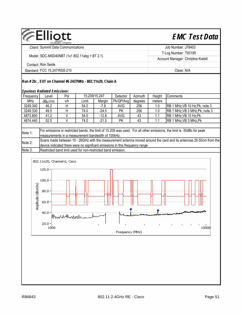
Run # 2b: , EUT on Channel #6 2437MHz - 802.11n20, Chain A
Spurious Radiated Emissions:Frequency Level Pol Detector Azimuth Height Comments
MHz dBμV/m v/h Limit Margin Pk/QP/Avg degrees meters3249.340 46.2 H 54.0 -7.8 AVG 256 1.0 RB 1 MHz;VB 10 Hz;Pk, note 33249.330 49.5 H 74.0 -24.5 PK 256 1.0 RB 1 MHz;VB 3 MHz;Pk, note 34873.800 41.2 V 54.0 -12.8 AVG 43 1.1 RB 1 MHz;VB 10 Hz;Pk4874.440 52.5 V 74.0 -21.5 PK 43 1.1 RB 1 MHz;VB 3 MHz;Pk
Note 1:
Note 2:
Note 3:
15.209/15.247
For emissions in restricted bands, the limit of 15.209 was used. For all other emissions, the limit is -30dBc for peak measurements in a measurement bandwidth of 100kHz.Scans made between 10 - 26GHz with the measurement antenna moved around the card and its antennas 20-50cm from the device indicated there were no signifcant emissions in this frequency rangeRestricted band limit used for non-restricted band emission.
R86843 802.11 2.4GHz RE - Cisco Page 51

EMC Test DataClient:
Contact:Standard:
Christine Krebill
Summit Data Communications Job Number: J78403
Model: SDC-MSD40NBT (1x1 802.11abg + BT 2.1)T-Log Number: T83195
Account Manager:Ron SeideFCC 15.247/RSS-210 Class: N/A
Run # 3, Radiated Spurious Emissions, 1-26GHz, 802.11n20 MCS0, Chain A
Run # 3a, EUT on Channel #1 2412MHz - 802.11n20 MCS0, Chain A
Spurious Radiated Emissions:Frequency Level Pol Detector Azimuth Height Comments
MHz dBμV/m v/h Limit Margin Pk/QP/Avg degrees meters3216.000 46.0 H 54.0 -8.0 AVG 258 1.0 RB 1 MHz;VB 10 Hz;Pk, note 23215.970 49.4 H 74.0 -24.6 PK 258 1.0 RB 1 MHz;VB 3 MHz;Pk, note 24822.660 39.5 V 54.0 -14.5 AVG 64 1.2 RB 1 MHz;VB 10 Hz;Pk4821.960 51.8 V 74.0 -22.2 PK 64 1.2 RB 1 MHz;VB 3 MHz;Pk
Note 1:
Note 2:
Test Engineer: Rafael Varelas Config Change: None
15.209/15.247
Date of Test: 5/19/2011 Test Location: FT Chamber #7
For emissions in restricted bands, the limit of 15.209 was used. For all other emissions, the limit is -30dBc for peak measurements in a measurement bandwidth of 100kHz.Restricted band limit used for non-restricted band emission.
R86843 802.11 2.4GHz RE - Cisco Page 52

EMC Test DataClient:
Contact:Standard:
Christine Krebill
Summit Data Communications Job Number: J78403
Model: SDC-MSD40NBT (1x1 802.11abg + BT 2.1)T-Log Number: T83195
Account Manager:Ron SeideFCC 15.247/RSS-210 Class: N/A
Run # 3c: , EUT on Channel #11 2462MHz - 802.11n20 MCS0, Chain A
Spurious Radiated Emissions:Frequency Level Pol Detector Azimuth Height Comments
MHz dBμV/m v/h Limit Margin Pk/QP/Avg degrees meters3282.650 46.2 H 54.0 -7.8 AVG 248 1.2 RB 1 MHz;VB 10 Hz;Pk, note 23282.850 49.5 H 74.0 -24.5 PK 248 1.2 RB 1 MHz;VB 3 MHz;Pk, note 24923.650 36.2 V 54.0 -17.8 AVG 24 1.0 RB 1 MHz;VB 10 Hz;Pk4927.630 49.8 V 74.0 -24.2 PK 24 1.0 RB 1 MHz;VB 3 MHz;Pk
Note 1:
Note 2:
15.209/15.247
For emissions in restricted bands, the limit of 15.209 was used. For all other emissions, the limit is -30dBc for peak measurements in a measurement bandwidth of 100kHz.Restricted band limit used for non-restricted band emission.
R86843 802.11 2.4GHz RE - Cisco Page 53
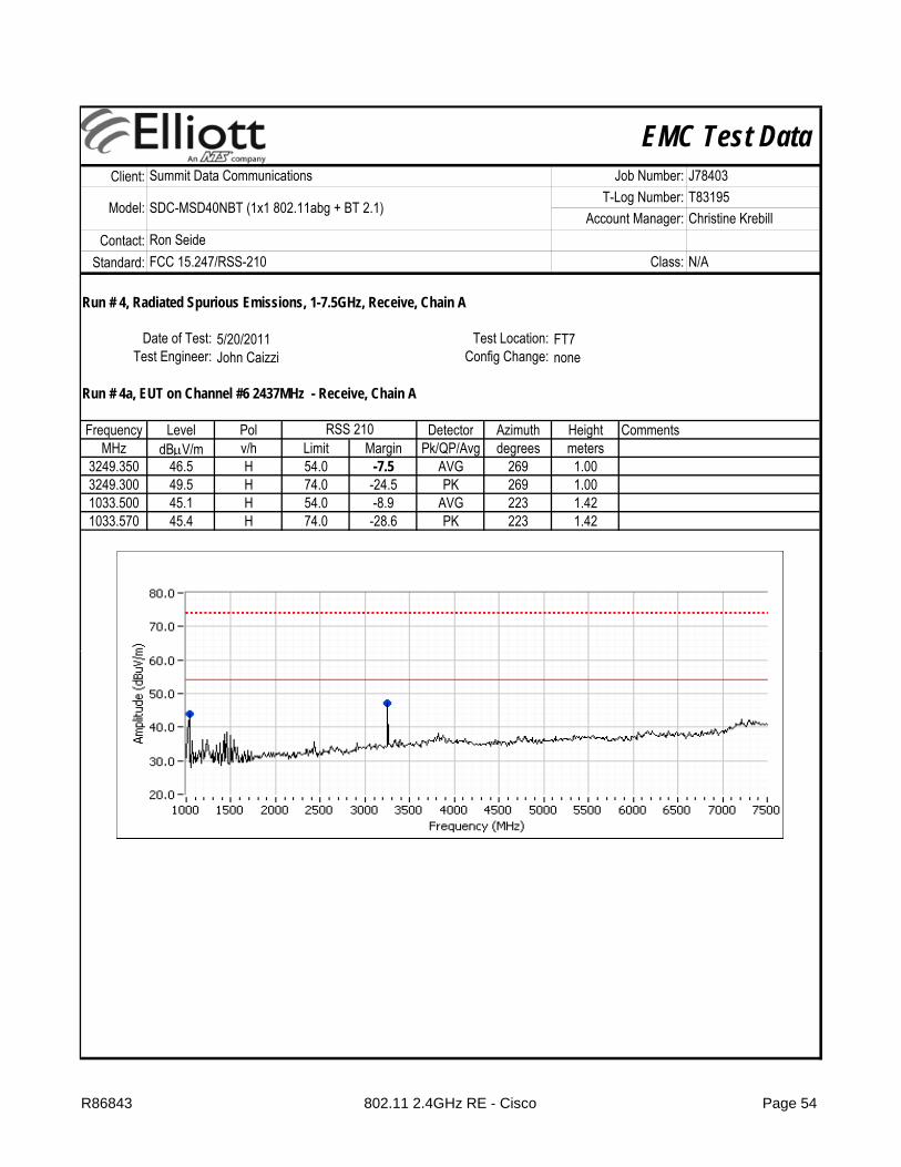
EMC Test DataClient:
Contact:Standard:
Christine Krebill
Summit Data Communications Job Number: J78403
Model: SDC-MSD40NBT (1x1 802.11abg + BT 2.1)T-Log Number: T83195
Account Manager:Ron SeideFCC 15.247/RSS-210 Class: N/A
Run # 4, Radiated Spurious Emissions, 1-7.5GHz, Receive, Chain A
Run # 4a, EUT on Channel #6 2437MHz - Receive, Chain A
Frequency Level Pol Detector Azimuth Height CommentsMHz dBμV/m v/h Limit Margin Pk/QP/Avg degrees meters
3249.350 46.5 H 54.0 -7.5 AVG 269 1.003249.300 49.5 H 74.0 -24.5 PK 269 1.001033.500 45.1 H 54.0 -8.9 AVG 223 1.421033.570 45.4 H 74.0 -28.6 PK 223 1.42
RSS 210
Test Engineer: John Caizzi Config Change: noneDate of Test: 5/20/2011 Test Location: FT7
R86843 802.11 2.4GHz RE - Cisco Page 54
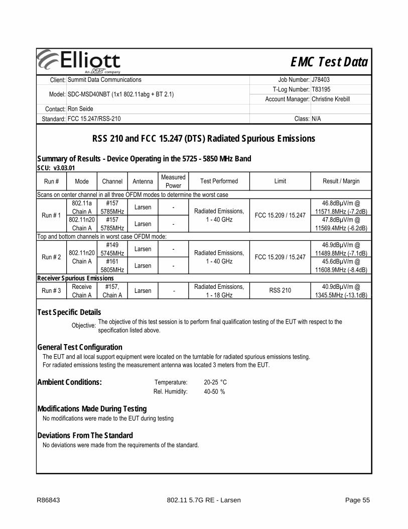
EMC Test DataClient:
Contact:Standard:
Summary of Results - Device Operating in the 5725 - 5850 MHz BandSCU: v3.03.01
Run # Mode Channel Antenna Measured Power
Scans on center channel in all three OFDM modes to determine the worst case802.11aChain A
#157 5785MHz Larsen -
802.11n20Chain A
#157 5785MHz Larsen -
Top and bottom channels in worst case OFDM mode:#149
5745MHz Larsen -
#161 5805MHz Larsen -
Receiver Spurious Emissions
Run # 3 ReceiveChain A
#157, Chain A Larsen -
Summit Data Communications Job Number: J78403
Model: SDC-MSD40NBT (1x1 802.11abg + BT 2.1)T-Log Number: T83195
Account Manager: Christine Krebill
46.8dBµV/m @ 11571.8MHz (-7.2dB)
47.8dBµV/m @ 11569.4MHz (-6.2dB)
Ron SeideFCC 15.247/RSS-210 Class: N/A
Radiated Emissions,1 18 GHz
RSS 210 40.9dBµV/m @ 1345 5MHz ( 13 1dB)
RSS 210 and FCC 15.247 (DTS) Radiated Spurious Emissions
Test Performed Limit Result / Margin
Run # 1 Radiated Emissions,1 - 40 GHz FCC 15.209 / 15.247
Run # 2 802.11n20Chain A
Radiated Emissions,1 - 40 GHz FCC 15.209 / 15.247
46.9dBµV/m @ 11489.8MHz (-7.1dB)
45.6dBµV/m @ 11608.9MHz (-8.4dB)
Chain A Chain A
Test Specific Details
General Test Configuration
Ambient Conditions: Temperature: 20-25 °CRel. Humidity: 40-50 %
1 - 18 GHz 1345.5MHz (-13.1dB)
For radiated emissions testing the measurement antenna was located 3 meters from the EUT.
Modifications Made During TestingNo modifications were made to the EUT during testing
The EUT and all local support equipment were located on the turntable for radiated spurious emissions testing.
Deviations From The Standard
Objective: The objective of this test session is to perform final qualification testing of the EUT with respect to the specification listed above.
No deviations were made from the requirements of the standard.
R86843 802.11 5.7G RE - Larsen Page 55
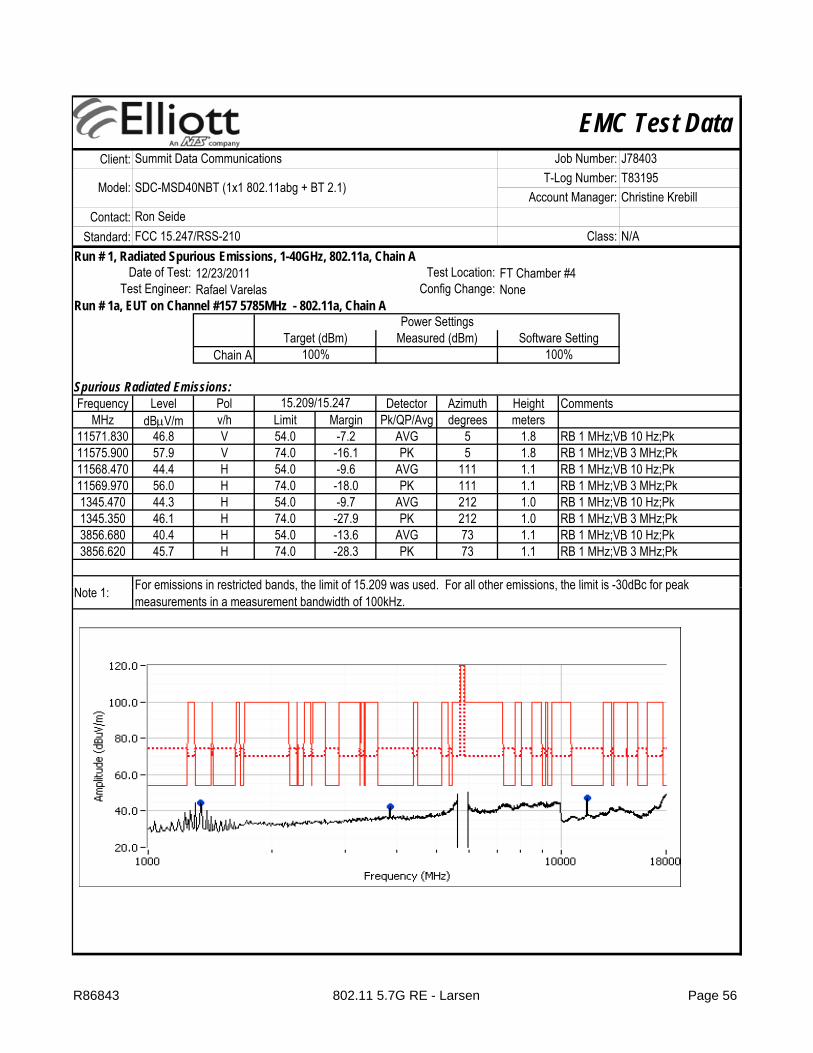
EMC Test DataClient:
Contact:Standard:
Summit Data Communications Job Number: J78403
Model: SDC-MSD40NBT (1x1 802.11abg + BT 2.1)T-Log Number: T83195
Account Manager: Christine KrebillRon SeideFCC 15.247/RSS-210 Class: N/A
Run # 1, Radiated Spurious Emissions, 1-40GHz, 802.11a, Chain A
Run # 1a, EUT on Channel #157 5785MHz - 802.11a, Chain A
Chain A
Spurious Radiated Emissions:Frequency Level Pol Detector Azimuth Height Comments
MHz dBμV/m v/h Limit Margin Pk/QP/Avg degrees meters11571.830 46.8 V 54.0 -7.2 AVG 5 1.8 RB 1 MHz;VB 10 Hz;Pk11575.900 57.9 V 74.0 -16.1 PK 5 1.8 RB 1 MHz;VB 3 MHz;Pk11568.470 44.4 H 54.0 -9.6 AVG 111 1.1 RB 1 MHz;VB 10 Hz;Pk11569.970 56.0 H 74.0 -18.0 PK 111 1.1 RB 1 MHz;VB 3 MHz;Pk1345.470 44.3 H 54.0 -9.7 AVG 212 1.0 RB 1 MHz;VB 10 Hz;Pk1345.350 46.1 H 74.0 -27.9 PK 212 1.0 RB 1 MHz;VB 3 MHz;Pk3856.680 40.4 H 54.0 -13.6 AVG 73 1.1 RB 1 MHz;VB 10 Hz;Pk3856.620 45.7 H 74.0 -28.3 PK 73 1.1 RB 1 MHz;VB 3 MHz;Pk
N 1
Power SettingsTarget (dBm) Measured (dBm) Software Setting
Date of Test: 12/23/2011 Test Location: FT Chamber #4
For emissions in restricted bands the limit of 15 209 was used For all other emissions the limit is -30dBc for peak
Test Engineer: Rafael Varelas Config Change: None
15.209/15.247
100% 100%
Note 1: For emissions in restricted bands, the limit of 15.209 was used. For all other emissions, the limit is 30dBc for peak measurements in a measurement bandwidth of 100kHz.
R86843 802.11 5.7G RE - Larsen Page 56
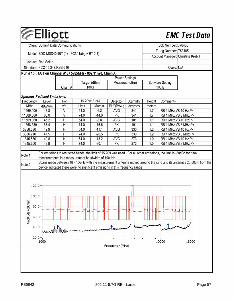
EMC Test DataClient:
Contact:Standard:
Summit Data Communications Job Number: J78403
Model: SDC-MSD40NBT (1x1 802.11abg + BT 2.1)T-Log Number: T83195
Account Manager: Christine KrebillRon SeideFCC 15.247/RSS-210 Class: N/A
Run # 1b: , EUT on Channel #157 5785MHz - 802.11n20, Chain A
Chain A
Spurious Radiated Emissions:Frequency Level Pol Detector Azimuth Height Comments
MHz dBμV/m v/h Limit Margin Pk/QP/Avg degrees meters11569.400 47.8 V 54.0 -6.2 AVG 341 1.7 RB 1 MHz;VB 10 Hz;Pk11568.560 60.0 V 74.0 -14.0 PK 341 1.7 RB 1 MHz;VB 3 MHz;Pk11569.960 45.2 H 54.0 -8.8 AVG 101 1.1 RB 1 MHz;VB 10 Hz;Pk11568.530 57.4 H 74.0 -16.6 PK 101 1.1 RB 1 MHz;VB 3 MHz;Pk3856.680 42.9 H 54.0 -11.1 AVG 330 1.2 RB 1 MHz;VB 10 Hz;Pk3856.710 47.5 H 74.0 -26.5 PK 330 1.2 RB 1 MHz;VB 3 MHz;Pk1345.530 40.8 H 54.0 -13.2 AVG 273 1.0 RB 1 MHz;VB 10 Hz;Pk1345.600 43.9 H 74.0 -30.1 PK 273 1.0 RB 1 MHz;VB 3 MHz;Pk
Note 1:
Note 2:
100% 100%
15.209/15.247
Target (dBm) Measured (dBm) Software SettingPower Settings
For emissions in restricted bands, the limit of 15.209 was used. For all other emissions, the limit is -30dBc for peak measurements in a measurement bandwidth of 100kHz.Scans made between 18 - 40GHz with the measurement antenna moved around the card and its antennas 20-50cm from the device indicated there were no signifcant emissions in this frequency rangedevice indicated there were no signifcant emissions in this frequency range
R86843 802.11 5.7G RE - Larsen Page 57

EMC Test DataClient:
Contact:Standard:
Summit Data Communications Job Number: J78403
Model: SDC-MSD40NBT (1x1 802.11abg + BT 2.1)T-Log Number: T83195
Account Manager: Christine KrebillRon SeideFCC 15.247/RSS-210 Class: N/A
Run # 2, Radiated Spurious Emissions, 1-40GHz, 802.11n20, Chain A
Run # 2a, EUT on Channel #149 5745MHz - 802.11n20, Chain A
Chain A
Spurious Radiated Emissions:Frequency Level Pol Detector Azimuth Height Comments
MHz dBμV/m v/h Limit Margin Pk/QP/Avg degrees meters11489.770 46.9 V 54.0 -7.1 AVG 95 1.5 RB 1 MHz;VB 10 Hz;Pk11490.400 59.1 V 74.0 -14.9 PK 95 1.5 RB 1 MHz;VB 3 MHz;Pk11489.870 45.1 H 54.0 -8.9 AVG 102 1.0 RB 1 MHz;VB 10 Hz;Pk11487.330 56.5 H 74.0 -17.5 PK 102 1.0 RB 1 MHz;VB 3 MHz;Pk3830.000 41.6 H 54.0 -12.4 AVG 329 1.0 RB 1 MHz;VB 10 Hz;Pk3830.000 46.2 H 74.0 -27.8 PK 329 1.0 RB 1 MHz;VB 3 MHz;Pk1306.370 41.4 V 54.0 -12.6 AVG 169 1.2 RB 1 MHz;VB 10 Hz;Pk1306.430 44.8 V 74.0 -29.2 PK 169 1.2 RB 1 MHz;VB 3 MHz;Pk
N 1
Software Setting
Date of Test: 12/23/2011 Test Location: FT Chamber #4
For emissions in restricted bands the limit of 15 209 was used For all other emissions the limit is -30dBc for peak
Test Engineer: Rafael Varelas Config Change: None
Power SettingsTarget (dBm) Measured (dBm)
100% 100%
15.209/15.247
Note 1: For emissions in restricted bands, the limit of 15.209 was used. For all other emissions, the limit is 30dBc for peak measurements in a measurement bandwidth of 100kHz.
R86843 802.11 5.7G RE - Larsen Page 58

EMC Test DataClient:
Contact:Standard:
Summit Data Communications Job Number: J78403
Model: SDC-MSD40NBT (1x1 802.11abg + BT 2.1)T-Log Number: T83195
Account Manager: Christine KrebillRon SeideFCC 15.247/RSS-210 Class: N/A
Run # 2c: , EUT on Channel #161 5805MHz - 802.11n20, Chain A
Chain A
Spurious Radiated Emissions:Frequency Level Pol Detector Azimuth Height Comments
MHz dBμV/m v/h Limit Margin Pk/QP/Avg degrees meters11608.940 45.6 H 54.0 -8.4 AVG 88 1.0 RB 1 MHz;VB 10 Hz;Pk11612.840 57.5 H 74.0 -16.5 PK 88 1.0 RB 1 MHz;VB 3 MHz;Pk11608.910 45.4 V 54.0 -8.6 AVG 89 1.0 RB 1 MHz;VB 10 Hz;Pk11607.080 56.7 V 74.0 -17.3 PK 89 1.0 RB 1 MHz;VB 3 MHz;Pk1306.550 44.9 V 54.0 -9.1 AVG 206 1.0 RB 1 MHz;VB 10 Hz;Pk1306.430 46.9 V 74.0 -27.1 PK 206 1.0 RB 1 MHz;VB 3 MHz;Pk3870.040 42.4 H 54.0 -11.6 AVG 322 1.4 RB 1 MHz;VB 10 Hz;Pk3869.890 47.5 H 74.0 -26.5 PK 322 1.4 RB 1 MHz;VB 3 MHz;Pk
Note 1:
Power SettingsTarget (dBm) Measured (dBm) Software Setting
100% 100%
15.209/15.247
For emissions in restricted bands, the limit of 15.209 was used. For all other emissions, the limit is -30dBc for peak measurements in a measurement bandwidth of 100kHz.
R86843 802.11 5.7G RE - Larsen Page 59
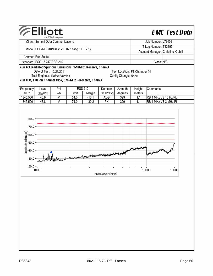
EMC Test DataClient:
Contact:Standard:
Summit Data Communications Job Number: J78403
Model: SDC-MSD40NBT (1x1 802.11abg + BT 2.1)T-Log Number: T83195
Account Manager: Christine KrebillRon SeideFCC 15.247/RSS-210 Class: N/A
Run # 3, Radiated Spurious Emissions, 1-18GHz, Receive, Chain A
Run # 3a, EUT on Channel #157, 5785MHz - Receive, Chain A
Frequency Level Pol Detector Azimuth Height CommentsMHz dBμV/m v/h Limit Margin Pk/QP/Avg degrees meters
1345.500 40.9 V 54.0 -13.1 AVG 329 1.1 RB 1 MHz;VB 10 Hz;Pk1345.500 43.8 V 74.0 -30.2 PK 329 1.1 RB 1 MHz;VB 3 MHz;Pk
12/23/2011 FT Chamber #4Test Location:
RSS 210
Test Engineer: Rafael Varelas Config Change: NoneDate of Test:
R86843 802.11 5.7G RE - Larsen Page 60

EMC Test DataClient:
Contact:Standard:
Test Specific Details
General Test Configuration
Ambient Conditions:Temperature: 23 °C
The EUT was connected to the spectrum analyzer or power meter via a suitable attenuator. All measurements were made on a single chain.
All measurements have been corrected to allow for the external attenuators used.
Test Engineer: Joseph Cadigal Config Change: no antennasTest Location: FT Lab #4 EUT Voltage: 3.3 VDC
RSS 210 and FCC 15.247 (DTS) Antenna Port MeasurementsPower, PSD, Bandwidth and Spurious Emissions
Objective: The objective of this test session is to perform final qualification testing of the EUT with respect to the specification listed above.
Date of Test: 2/6/2012 Config. Used: 2
Ron SeideFCC 15.247/RSS-210 Class: N/A
Summit Data Communications Job Number: J78403
Model: SDC-MSD40NBT (1x1 802.11abg + BT 2.1)T-Log Number: T83195
Account Manager: Christine Krebill
Rel. Humidity: 37 %
Summary of Results
Run # Pwr setting Avg Pwr Pass / Fail1 - - Pass
Test Performed Limit Result / Margin
Deviations From The StandardNo deviations were made from the requirements of the standard.
Output Power 15.247(b) See Below
Modifications Made During TestingNo modifications were made to the EUT during testing
R86843 DTS Power Page 61
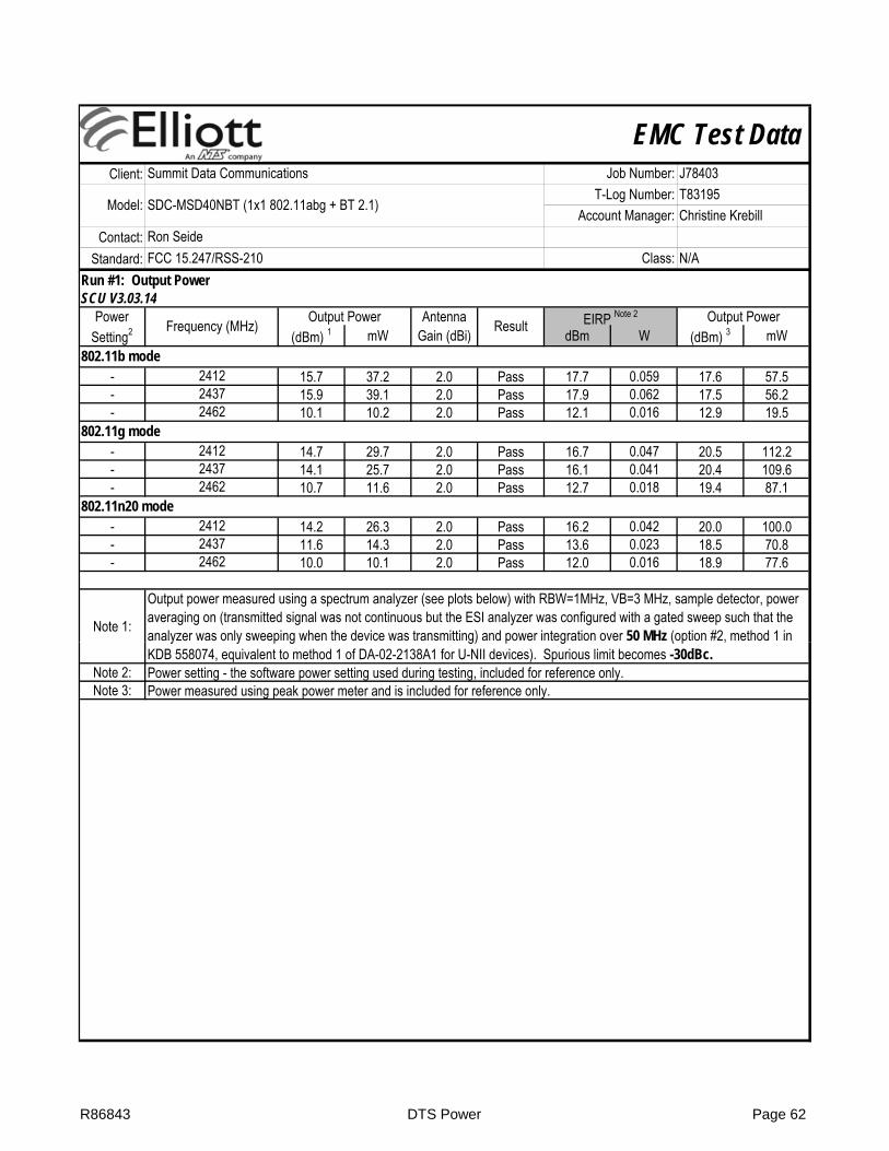
EMC Test DataClient:
Contact:Standard:
Ron SeideFCC 15.247/RSS-210 Class: N/A
Summit Data Communications Job Number: J78403
Model: SDC-MSD40NBT (1x1 802.11abg + BT 2.1)T-Log Number: T83195
Account Manager: Christine Krebill
Run #1: Output PowerSCU V3.03.14
Power Antenna Setting2 (dBm) 1 mW Gain (dBi) dBm W (dBm) 3 mW
- 15.7 37.2 2.0 Pass 17.7 0.059 17.6 57.5- 15.9 39.1 2.0 Pass 17.9 0.062 17.5 56.2- 10.1 10.2 2.0 Pass 12.1 0.016 12.9 19.5
- 14.7 29.7 2.0 Pass 16.7 0.047 20.5 112.2- 14.1 25.7 2.0 Pass 16.1 0.041 20.4 109.6- 10.7 11.6 2.0 Pass 12.7 0.018 19.4 87.1
- 14.2 26.3 2.0 Pass 16.2 0.042 20.0 100.0- 11.6 14.3 2.0 Pass 13.6 0.023 18.5 70.8- 10.0 10.1 2.0 Pass 12.0 0.016 18.9 77.6
Note 1:
Output power measured using a spectrum analyzer (see plots below) with RBW=1MHz, VB=3 MHz, sample detector, power averaging on (transmitted signal was not continuous but the ESI analyzer was configured with a gated sweep such that the analyzer was only sweeping when the device was transmitting) and power integration over 50 MHz (option #2, method 1 in
Output Power
24372462
802.11b mode2412
802.11g mode2412
2462
24372462
802.11n20 mode2412
Frequency (MHz) Output Power Result EIRP Note 2
2437
Note 2:Note 3:
y y p g g) p g ( p ,KDB 558074, equivalent to method 1 of DA-02-2138A1 for U-NII devices). Spurious limit becomes -30dBc.Power setting - the software power setting used during testing, included for reference only.Power measured using peak power meter and is included for reference only.
R86843 DTS Power Page 62

EMC Test DataClient:
Contact:Standard:
Ron SeideFCC 15.247/RSS-210 Class: N/A
Summit Data Communications Job Number: J78403
Model: SDC-MSD40NBT (1x1 802.11abg + BT 2.1)T-Log Number: T83195
Account Manager: Christine Krebill
R86843 DTS Power Page 63

EMC Test DataClient:
Contact:Standard:
Ron SeideFCC 15.247/RSS-210 Class: N/A
Summit Data Communications Job Number: J78403
Model: SDC-MSD40NBT (1x1 802.11abg + BT 2.1)T-Log Number: T83195
Account Manager: Christine Krebill
Power Antenna Setting2 (dBm) 1 mW Gain (dBi) dBm W (dBm) 3 mW
- 15.7 37.2 5.0 Pass 20.7 0.117 19.1 81.3- 15.5 35.5 5.0 Pass 20.5 0.112 18.7 74.1- 15.8 38.0 5.0 Pass 20.8 0.120 18.6 72.4
- 15.7 37.2 5.0 Pass 20.7 0.117 19.1 81.3- 15.4 34.7 5.0 Pass 20.4 0.110 18.6 72.4- 15.3 33.9 5.0 Pass 20.3 0.107 18.4 69.2
Note 1:
Note 2:Note 3:
Frequency (MHz) Output Power Result EIRP Note 2
5745802.11a mode
Power measured using peak power meter and is included for reference only.
57855805
802.11n20 mode574557855805
Output power measured using a spectrum analyzer (see plots below) with RBW=1MHz, VB=3 MHz, sample detector, power averaging on (transmitted signal was not continuous but the ESI analyzer was configured with a gated sweep such that the analyzer was only sweeping when the device was transmitting) and power integration over 50 MHz (option #2, method 1 in KDB 558074, equivalent to method 1 of DA-02-2138A1 for U-NII devices). Spurious limit becomes -30dBc.Power setting - the software power setting used during testing, included for reference only.
Output Power
R86843 DTS Power Page 64

EMC Test DataClient:
Contact:Standard:
Test Specific Details
General Test Configuration
Ambient Conditions:Temperature: 23 °C
The EUT was connected to the spectrum analyzer or power meter via a suitable attenuator. All measurements were made on a single chain.
All measurements have been corrected to allow for the external attenuators used.
John Caizzi / Rafael Varelas Config Change: no antennasTest Location: FT Lab #4 EUT Voltage: 3.3 VDCTest Engineer:
RSS 210 and FCC 15.247 (DTS) Antenna Port Measurements (802.11b)Power, PSD, Bandwidth and Spurious Emissions
Objective: The objective of this test session is to perform final qualification testing of the EUT with respect to the specification listed above.
Date of Test: 8/23/2011 Config. Used: 2
Ron SeideFCC 15.247/RSS-210 Class: N/A
Summit Data Communications Job Number: J78403
Model: SDC-MSD40NBT (1x1 802.11abg + BT 2.1)T-Log Number: T83195
Account Manager: Christine Krebill
Rel. Humidity: 37 %
Summary of Results
Run # Pwr setting Avg Pwr Pass / Fail2 - - Pass3 - - Pass3 - - -4 - - PassSpurious emissions 15.247(b)
Modifications Made During TestingNo modifications were made to the EUT during testing
All emissions < -30 dBc
Deviations From The StandardNo deviations were made from the requirements of the standard.
Minimum 6dB Bandwidth 15.247(a) 9.0 MHz99% Bandwidth RSS GEN 12.8 MHz
Power spectral Density (PSD) 15.247(d) -5.3 dBm/3kHzTest Performed Limit Result / Margin
R86843 802.11b Antenna Page 65

EMC Test DataClient:
Contact:Standard:
Ron SeideFCC 15.247/RSS-210 Class: N/A
Summit Data Communications Job Number: J78403
Model: SDC-MSD40NBT (1x1 802.11abg + BT 2.1)T-Log Number: T83195
Account Manager: Christine Krebill
Run #2: Power spectral Density
Power Limit ResultSetting dBm/3kHz
- 8.0 Pass- 8.0 Pass- 8.0 Pass
Note 1:
2437.7377 -5.3
Power spectral density measured using RB=3 kHz, VB=10kHz, analyzer with peak detector and with a sweep time set to ensure a dwell time of at least 1 second per 3kHz. The measurement is made at the frequency of PPSD determined from preliminary scans using RB=3kHz using multiple sweeps at a faster rate over the 6dB bandwidth of the signal.
2461.1764 -6.2
2412.697 -7.5
Frequency (MHz) PSD(dBm/3kHz) Note 1
R86843 802.11b Antenna Page 66

EMC Test DataClient:
Contact:Standard:
Ron SeideFCC 15.247/RSS-210 Class: N/A
Summit Data Communications Job Number: J78403
Model: SDC-MSD40NBT (1x1 802.11abg + BT 2.1)T-Log Number: T83195
Account Manager: Christine Krebill
Run #3: Signal Bandwidth
6dB 99%- 100kHz 9.0 12.8- 100kHz 9.1 12.5- 100kHz 9.1 12.7
Note 1:
241224372462
99% bandwidth measured in accordance with RSS GEN, with RB > 1% of the span and VB > 3xRB
Power Setting
Frequency (MHz) Resolution Bandwidth
Bandwidth (MHz)
Run #4: Out of Band Spurious Emissions
2462 -30dBc Pass
2412 -30dBc Pass2437 -30dBc Pass
Frequency (MHz) Limit Result
R86843 802.11b Antenna Page 67
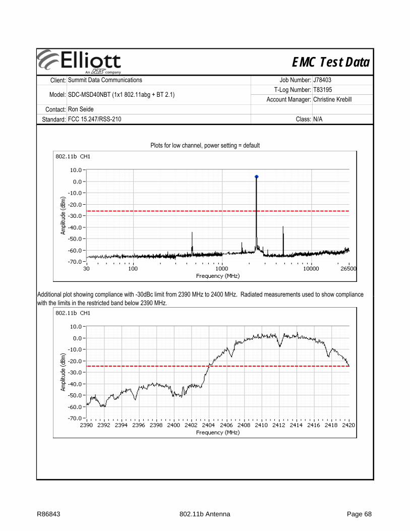
EMC Test DataClient:
Contact:Standard:
Ron SeideFCC 15.247/RSS-210 Class: N/A
Summit Data Communications Job Number: J78403
Model: SDC-MSD40NBT (1x1 802.11abg + BT 2.1)T-Log Number: T83195
Account Manager: Christine Krebill
Plots for low channel, power setting = default
Additional plot showing compliance with -30dBc limit from 2390 MHz to 2400 MHz. Radiated measurements used to show compliance Additional plot showing compliance with 30dBc limit from 2390 MHz to 2400 MHz. Radiated measurements used to show compliance with the limits in the restricted band below 2390 MHz.
R86843 802.11b Antenna Page 68

EMC Test DataClient:
Contact:Standard:
Ron SeideFCC 15.247/RSS-210 Class: N/A
Summit Data Communications Job Number: J78403
Model: SDC-MSD40NBT (1x1 802.11abg + BT 2.1)T-Log Number: T83195
Account Manager: Christine Krebill
Plots for high channel, power setting = default
Plots for center channel, power setting = default
R86843 802.11b Antenna Page 69

EMC Test DataClient:
Contact:Standard:
Test Specific Details
General Test Configuration
Ambient Conditions:Temperature: 23 °C
The EUT was connected to the spectrum analyzer or power meter via a suitable attenuator. All measurements were made on a single chain.
All measurements have been corrected to allow for the external attenuators used.
Test Engineer: Joseph Cadigal Config Change: no antennasTest Location: FT Lab #4 EUT Voltage: 3.3 VDC
RSS 210 and FCC 15.247 (DTS) Antenna Port Measurements (802.11g)Power, PSD, Bandwidth and Spurious Emissions
Objective: The objective of this test session is to perform final qualification testing of the EUT with respect to the specification listed above.
Date of Test: 2/6/2012 Config. Used: 2
Ron SeideFCC 15.247/RSS-210 Class: N/A
Summit Data Communications Job Number: J78403
Model: SDC-MSD40NBT (1x1 802.11abg + BT 2.1)T-Log Number: T83195
Account Manager: Christine Krebill
Rel. Humidity: 37 %
Summary of Results
Run # Pwr setting Avg Pwr Pass / Fail2 default - Pass 3 default - Pass 3 default - -4 default - Pass All emissions < -30 dBc
Modifications Made During Testing
No deviations were made from the requirements of the standard.
No modifications were made to the EUT during testing
Deviations From The Standard
Minimum 6dB Bandwidth 15.247(a) 15.1 MHz99% Bandwidth RSS GEN 18.5 MHz
Spurious emissions 15.247(b)
Test Performed Limit Result / MarginPower spectral Density (PSD) 15.247(d) -12.3 dBm/3kHz
R86843 802.11g Antenna Page 70

EMC Test DataClient:
Contact:Standard:
Ron SeideFCC 15.247/RSS-210 Class: N/A
Summit Data Communications Job Number: J78403
Model: SDC-MSD40NBT (1x1 802.11abg + BT 2.1)T-Log Number: T83195
Account Manager: Christine Krebill
Run #2: Power spectral Density
Power Limit ResultSetting dBm/3kHz
- 8.0 Pass- 8.0 Pass- 8.0 Pass
Note 1:
-14.7
Power spectral density measured using RB=3 kHz, VB=10kHz, analyzer with peak detector and with a sweep time set to ensure a dwell time of at least 1 second per 3kHz. The measurement is made at the frequency of PPSD determined from preliminary scans using RB=3kHz using multiple sweeps at a faster rate over the 6dB bandwidth of the signal.
2459.4993 -14.12436.966 -12.3
Frequency (MHz) PSD(dBm/3kHz) Note 1
2412.697
R86843 802.11g Antenna Page 71

EMC Test DataClient:
Contact:Standard:
Ron SeideFCC 15.247/RSS-210 Class: N/A
Summit Data Communications Job Number: J78403
Model: SDC-MSD40NBT (1x1 802.11abg + BT 2.1)T-Log Number: T83195
Account Manager: Christine Krebill
Run #3: Signal Bandwidth
6dB 99%- 100kHz 15.1 18.4- 100kHz 15.1 18.5- 100kHz 15.1 16.7
Note 1:
241224372462
99% bandwidth measured in accordance with RSS GEN, with RB > 1% of the span and VB > 3xRB
Power Setting
Frequency (MHz) Resolution Bandwidth
Bandwidth (MHz)
Run #4: Out of Band Spurious Emissions
2462 -30dBc Pass
Frequency (MHz) Limit2412 -30dBc Pass2437 -30dBc Pass
Result
R86843 802.11g Antenna Page 72
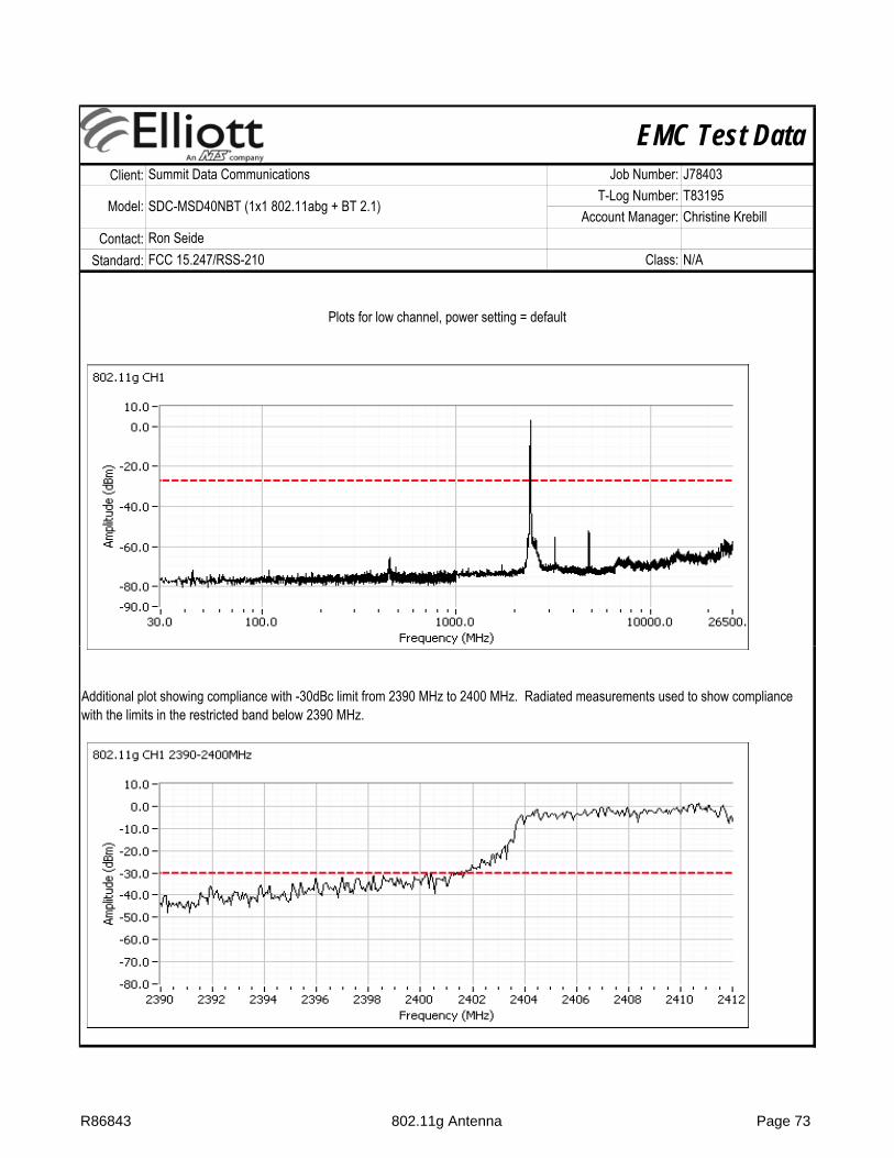
EMC Test DataClient:
Contact:Standard:
Ron SeideFCC 15.247/RSS-210 Class: N/A
Summit Data Communications Job Number: J78403
Model: SDC-MSD40NBT (1x1 802.11abg + BT 2.1)T-Log Number: T83195
Account Manager: Christine Krebill
Plots for low channel, power setting = default
Additional plot showing compliance with -30dBc limit from 2390 MHz to 2400 MHz. Radiated measurements used to show compliance with the limits in the restricted band below 2390 MHz.
R86843 802.11g Antenna Page 73

EMC Test DataClient:
Contact:Standard:
Ron SeideFCC 15.247/RSS-210 Class: N/A
Summit Data Communications Job Number: J78403
Model: SDC-MSD40NBT (1x1 802.11abg + BT 2.1)T-Log Number: T83195
Account Manager: Christine Krebill
Plots for center channel, power setting = default
Plots for high channel, power setting = default
R86843 802.11g Antenna Page 74
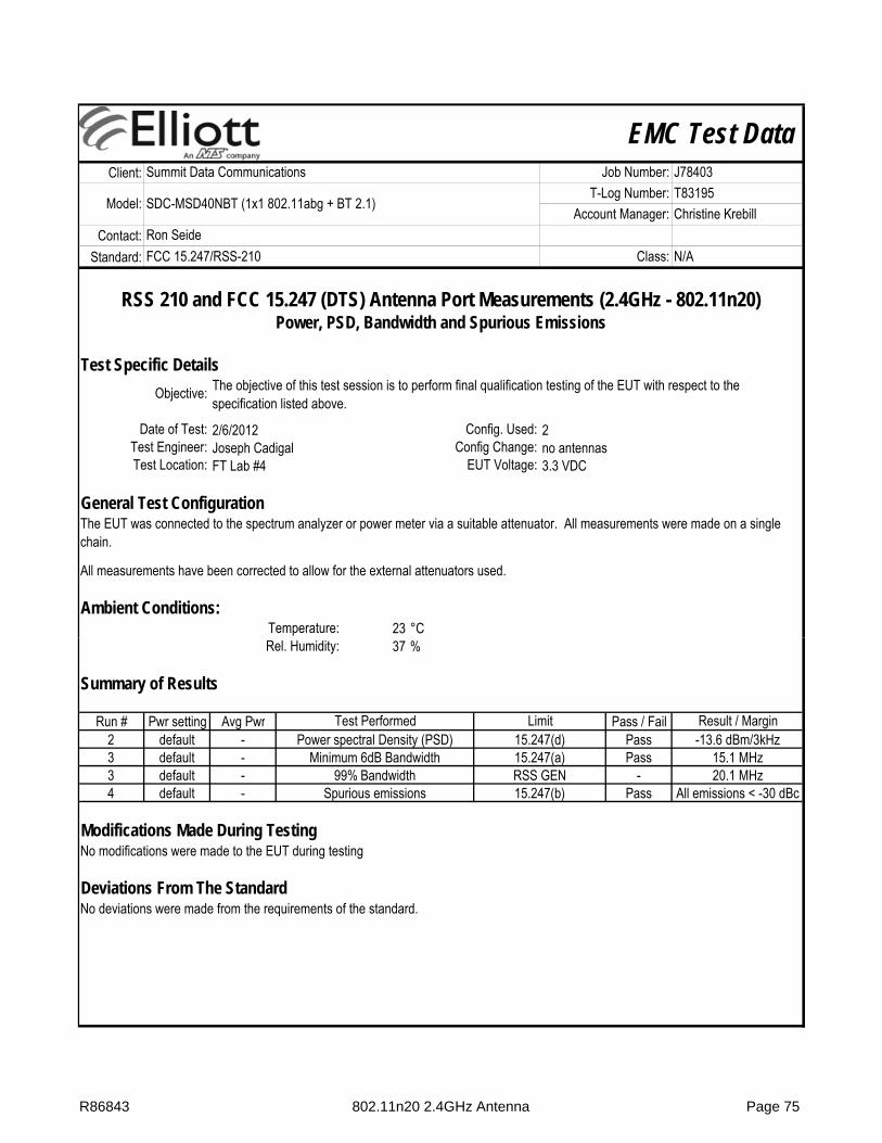
EMC Test DataClient:
Contact:Standard:
Test Specific Details
General Test Configuration
Ambient Conditions:Temperature: 23 °C
The EUT was connected to the spectrum analyzer or power meter via a suitable attenuator. All measurements were made on a single chain.
All measurements have been corrected to allow for the external attenuators used.
Joseph Cadigal Config Change: no antennasTest Location: FT Lab #4 EUT Voltage: 3.3 VDCTest Engineer:
RSS 210 and FCC 15.247 (DTS) Antenna Port Measurements (2.4GHz - 802.11n20)Power, PSD, Bandwidth and Spurious Emissions
Objective: The objective of this test session is to perform final qualification testing of the EUT with respect to the specification listed above.
Date of Test: 2/6/2012 Config. Used: 2
Ron SeideFCC 15.247/RSS-210 Class: N/A
Summit Data Communications Job Number: J78403
Model: SDC-MSD40NBT (1x1 802.11abg + BT 2.1)T-Log Number: T83195
Account Manager: Christine Krebill
Rel. Humidity: 37 %
Summary of Results
Run # Pwr setting Avg Pwr Pass / Fail2 default - Pass 3 default - Pass 3 default - -4 default - Pass
Deviations From The Standard
No modifications were made to the EUT during testing
Spurious emissions 15.247(b) All emissions < -30 dBc
Modifications Made During Testing
No deviations were made from the requirements of the standard.
Minimum 6dB Bandwidth 15.247(a) 15.1 MHz99% Bandwidth RSS GEN 20.1 MHz
Power spectral Density (PSD) 15.247(d) -13.6 dBm/3kHzTest Performed Limit Result / Margin
R86843 802.11n20 2.4GHz Antenna Page 75

EMC Test DataClient:
Contact:Standard:
Ron SeideFCC 15.247/RSS-210 Class: N/A
Summit Data Communications Job Number: J78403
Model: SDC-MSD40NBT (1x1 802.11abg + BT 2.1)T-Log Number: T83195
Account Manager: Christine Krebill
Run #2: Power spectral Density
Power Limit ResultSetting dBm/3kHz
100 8.0 Pass100 8.0 Pass100 8.0 Pass
Note 1:
2437 -13.62462 -14.3
Power spectral density measured using RB=3 kHz, VB=10kHz, analyzer with peak detector and with a sweep time set to ensure a dwell time of at least 1 second per 3kHz. The measurement is made at the frequency of PPSD determined from preliminary scans using RB=3kHz using multiple sweeps at a faster rate over the 6dB bandwidth of the signal.
(dBm/3kHz) Note 1
2412 -15.5
PSDFrequency (MHz)
R86843 802.11n20 2.4GHz Antenna Page 76

EMC Test DataClient:
Contact:Standard:
Ron SeideFCC 15.247/RSS-210 Class: N/A
Summit Data Communications Job Number: J78403
Model: SDC-MSD40NBT (1x1 802.11abg + BT 2.1)T-Log Number: T83195
Account Manager: Christine Krebill
Run #3: Signal Bandwidth
6dB 99%100 100kHz 15.2 19.1100 100kHz 15.1 20.1100 100kHz 15.1 18.7
Note 1:
2412
Bandwidth (MHz)Power Setting
Frequency (MHz)
24372462
99% bandwidth measured in accordance with RSS GEN, with RB > 1% of the span and VB > 3xRB
Resolution Bandwidth
R86843 802.11n20 2.4GHz Antenna Page 77

EMC Test DataClient:
Contact:Standard:
Ron SeideFCC 15.247/RSS-210 Class: N/A
Summit Data Communications Job Number: J78403
Model: SDC-MSD40NBT (1x1 802.11abg + BT 2.1)T-Log Number: T83195
Account Manager: Christine Krebill
Run #4: Out of Band Spurious Emissions
2462 -30dBc Pass
Plots for low channel, power setting(s) = default
2412 -30dBc Pass2437 -30dBc Pass
Frequency (MHz) Limit Result
Additional plot showing compliance with -30dBc limit from 2390 MHz to 2400 MHz. Radiated measurements used to show compliance with the limits in the restricted band below 2390 MHz.
R86843 802.11n20 2.4GHz Antenna Page 78

EMC Test DataClient:
Contact:Standard:
Ron SeideFCC 15.247/RSS-210 Class: N/A
Summit Data Communications Job Number: J78403
Model: SDC-MSD40NBT (1x1 802.11abg + BT 2.1)T-Log Number: T83195
Account Manager: Christine Krebill
Plots for center channel, power setting(s) = default
Plots for high channel, power setting(s) = default
R86843 802.11n20 2.4GHz Antenna Page 79

EMC Test DataClient:
Contact:Standard:
Test Specific Details
General Test Configuration
Ambient Conditions:Temperature: 23 °C
The EUT was connected to the spectrum analyzer or power meter via a suitable attenuator. All measurements were made on a single chain.
All measurements have been corrected to allow for the external attenuators used.
Test Engineer: Joseph Cadigal Config Change: no antennasTest Location: FT Lab #4 EUT Voltage: 3.3 VDC
RSS 210 and FCC 15.247 (DTS) Antenna Port Measurements (5GHz - 802.11a)Power, PSD, Bandwidth and Spurious Emissions
Objective: The objective of this test session is to perform final qualification testing of the EUT with respect to the specification listed above.
Date of Test: 2/8/2012 Config. Used: 2
Ron SeideFCC 15.247/RSS-210 Class: N/A
Summit Data Communications Job Number: J78403
Model: SDC-MSD40NBT (1x1 802.11abg + BT 2.1)T-Log Number: T83195
Account Manager: Christine Krebill
Rel. Humidity: 37 %
Summary of Results
Run # Pwr setting Avg Pwr Pass / Fail2 100% Pass 3 100% Pass 3 100% -4 100% PassSpurious emissions 15.247(b) All emissions < -30 dBc
Deviations From The StandardNo deviations were made from the requirements of the standard.
Modifications Made During TestingNo modifications were made to the EUT during testing
Minimum 6dB Bandwidth 15.247(a) 15.0 MHz99% Bandwidth RSS GEN 18.9 MHz
Test Performed Limit Result / MarginPower spectral Density (PSD) 15.247(d) -16.6 dBm/3kHz
R86843 802.11a 5GHz Antenna Page 80
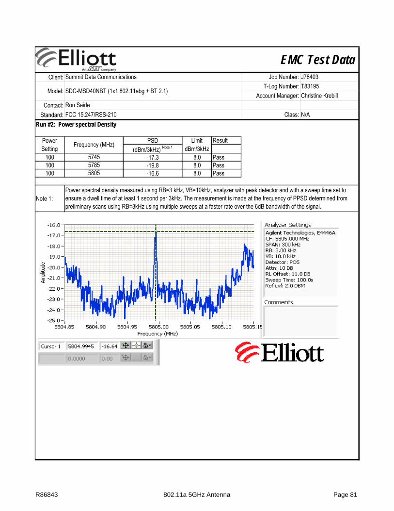
EMC Test DataClient:
Contact:Standard:
Ron SeideFCC 15.247/RSS-210 Class: N/A
Summit Data Communications Job Number: J78403
Model: SDC-MSD40NBT (1x1 802.11abg + BT 2.1)T-Log Number: T83195
Account Manager: Christine Krebill
Run #2: Power spectral Density
Power Limit ResultSetting dBm/3kHz
100 8.0 Pass100 8.0 Pass100 8.0 Pass
Note 1:
5785 -19.85805 -16.6
Power spectral density measured using RB=3 kHz, VB=10kHz, analyzer with peak detector and with a sweep time set to ensure a dwell time of at least 1 second per 3kHz. The measurement is made at the frequency of PPSD determined from preliminary scans using RB=3kHz using multiple sweeps at a faster rate over the 6dB bandwidth of the signal.
5745 -17.3
Frequency (MHz) PSD(dBm/3kHz) Note 1
R86843 802.11a 5GHz Antenna Page 81

EMC Test DataClient:
Contact:Standard:
Ron SeideFCC 15.247/RSS-210 Class: N/A
Summit Data Communications Job Number: J78403
Model: SDC-MSD40NBT (1x1 802.11abg + BT 2.1)T-Log Number: T83195
Account Manager: Christine Krebill
Run #3: Signal Bandwidth
6dB 99%100 100kHz 15.0 18.9100 100kHz 15.1 18.6100 100kHz 16.3 18.5
Note 1:
574557855805
99% bandwidth measured in accordance with RSS GEN, with RB > 1% of the span and VB > 3xRB
Power Setting
Frequency (MHz) Resolution Bandwidth
Bandwidth (MHz)
R86843 802.11a 5GHz Antenna Page 82
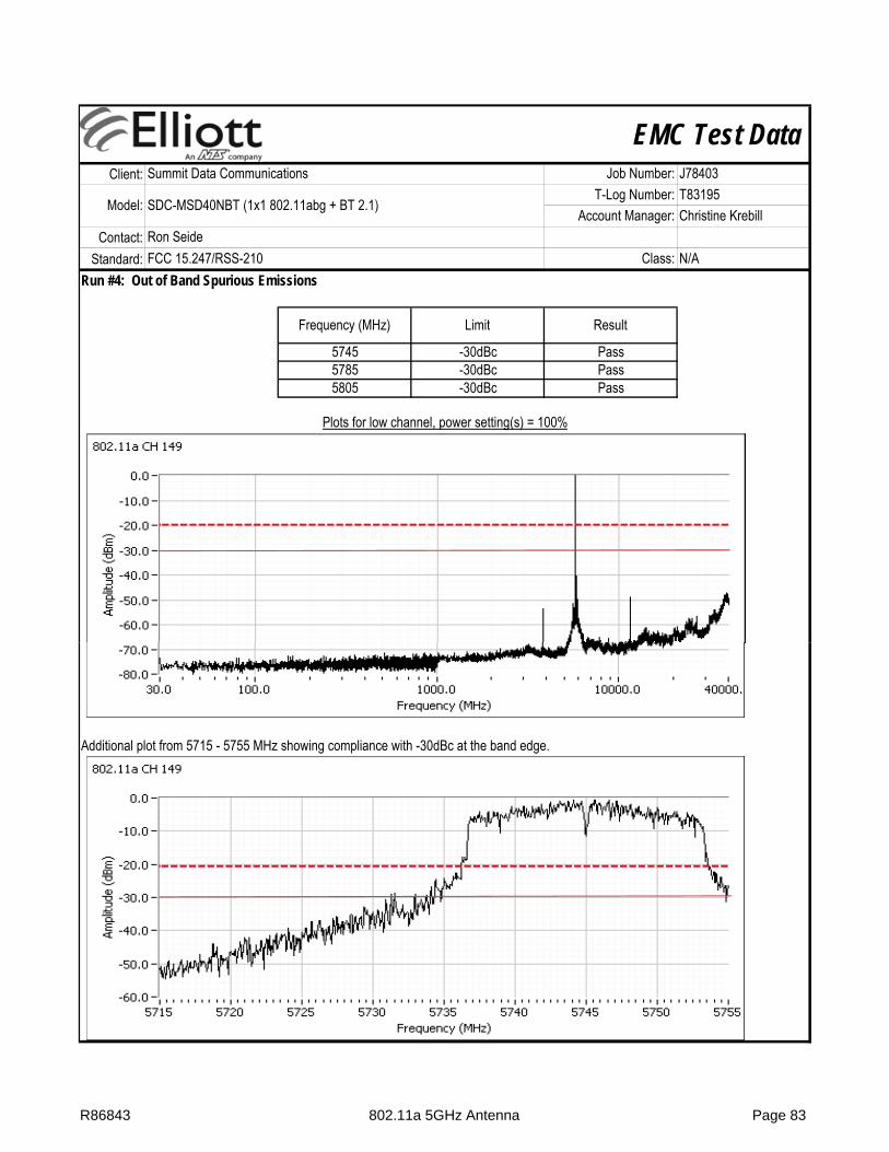
EMC Test DataClient:
Contact:Standard:
Ron SeideFCC 15.247/RSS-210 Class: N/A
Summit Data Communications Job Number: J78403
Model: SDC-MSD40NBT (1x1 802.11abg + BT 2.1)T-Log Number: T83195
Account Manager: Christine Krebill
Run #4: Out of Band Spurious Emissions
5805 -30dBc Pass
Plots for low channel, power setting(s) = 100%
Pass5785 -30dBc Pass
Frequency (MHz) Limit Result
5745 -30dBc
Additional plot from 5715 - 5755 MHz showing compliance with -30dBc at the band edge.
R86843 802.11a 5GHz Antenna Page 83

EMC Test DataClient:
Contact:Standard:
Ron SeideFCC 15.247/RSS-210 Class: N/A
Summit Data Communications Job Number: J78403
Model: SDC-MSD40NBT (1x1 802.11abg + BT 2.1)T-Log Number: T83195
Account Manager: Christine Krebill
Plots for center channel, power setting(s) = 100%
Plots for high channel, power setting(s) = 100%
R86843 802.11a 5GHz Antenna Page 84
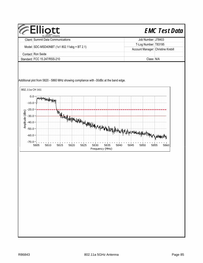
EMC Test DataClient:
Contact:Standard:
Ron SeideFCC 15.247/RSS-210 Class: N/A
Summit Data Communications Job Number: J78403
Model: SDC-MSD40NBT (1x1 802.11abg + BT 2.1)T-Log Number: T83195
Account Manager: Christine Krebill
Additional plot from 5820 - 5860 MHz showing compliance with -30dBc at the band edge.
R86843 802.11a 5GHz Antenna Page 85

EMC Test DataClient:
Contact:Standard:
Test Specific Details
General Test Configuration
Ambient Conditions:Temperature: 23 °C
The EUT was connected to the spectrum analyzer or power meter via a suitable attenuator. All measurements were made on a single chain.
All measurements have been corrected to allow for the external attenuators used.
Test Engineer: Joseph Cadigal Config Change: no antennasTest Location: FT Lab #4 EUT Voltage: 3.3 VDC
RSS 210 and FCC 15.247 (DTS) Antenna Port Measurements (5GHz - 802.11n20)Power, PSD, Bandwidth and Spurious Emissions
Objective: The objective of this test session is to perform final qualification testing of the EUT with respect to the specification listed above.
Date of Test: 2/6/2012 Config. Used: 2
Ron SeideFCC 15.247/RSS-210 Class: N/A
Summit Data Communications Job Number: J78403
Model: SDC-MSD40NBT (1x1 802.11abg + BT 2.1)T-Log Number: T83195
Account Manager: Christine Krebill
Rel. Humidity: 37 %
Summary of Results
Run # Pwr setting Avg Pwr Pass / Fail2 Default - Pass 3 Default - Pass 3 Default - -4 Default - Pass
No modifications were made to the EUT during testing
Deviations From The StandardNo deviations were made from the requirements of the standard.
Minimum 6dB Bandwidth 15.247(a) 15.0 MHz
Modifications Made During Testing
99% Bandwidth RSS GEN 22.8 MHzSpurious emissions 15.247(b) All emissions < -30 dBc
Test Performed Limit Result / MarginPower spectral Density (PSD) 15.247(d) -11.1 dBm/3kHz
R86843 802.11n20 5GHz Antenna Page 86

EMC Test DataClient:
Contact:Standard:
Ron SeideFCC 15.247/RSS-210 Class: N/A
Summit Data Communications Job Number: J78403
Model: SDC-MSD40NBT (1x1 802.11abg + BT 2.1)T-Log Number: T83195
Account Manager: Christine Krebill
Run #2: Power spectral Density
Power Limit ResultSetting dBm/3kHz
100 8.0 Pass100 8.0 Pass100 8.0 Pass
Note 1:
5745 -11.15785 -13.95805 -14.3
Power spectral density measured using RB=3 kHz, VB=10kHz, analyzer with peak detector and with a sweep time set to ensure a dwell time of at least 1 second per 3kHz. The measurement is made at the frequency of PPSD determined from preliminary scans using RB=3kHz using multiple sweeps at a faster rate over the 6dB bandwidth of the signal.
Frequency (MHz) PSD(dBm/3kHz) Note 1
R86843 802.11n20 5GHz Antenna Page 87

EMC Test DataClient:
Contact:Standard:
Ron SeideFCC 15.247/RSS-210 Class: N/A
Summit Data Communications Job Number: J78403
Model: SDC-MSD40NBT (1x1 802.11abg + BT 2.1)T-Log Number: T83195
Account Manager: Christine Krebill
Run #3: Signal Bandwidth
6dB 99%100 100kHz 15.0 16.9100 100kHz 15.2 22.8100 100kHz 15.1 21.4
Note 1:
5805
99% bandwidth measured in accordance with RSS GEN, with RB > 1% of the span and VB > 3xRB
Frequency (MHz) Resolution Bandwidth
Bandwidth (MHz)
57855745
Power Setting
R86843 802.11n20 5GHz Antenna Page 88

EMC Test DataClient:
Contact:Standard:
Ron SeideFCC 15.247/RSS-210 Class: N/A
Summit Data Communications Job Number: J78403
Model: SDC-MSD40NBT (1x1 802.11abg + BT 2.1)T-Log Number: T83195
Account Manager: Christine Krebill
Run #4: Out of Band Spurious Emissions
5805 -30dBc Pass
Plots for low channel, power setting(s) = 100%
5745 -30dBc Pass5785 -30dBc Pass
Frequency (MHz) Limit Result
Additional plot from 5715 - 5755 MHz showing compliance with -30dBc at the band edge.
R86843 802.11n20 5GHz Antenna Page 89

EMC Test DataClient:
Contact:Standard:
Ron SeideFCC 15.247/RSS-210 Class: N/A
Summit Data Communications Job Number: J78403
Model: SDC-MSD40NBT (1x1 802.11abg + BT 2.1)T-Log Number: T83195
Account Manager: Christine Krebill
Plots for center channel, power setting(s) = 100%
Plots for high channel, power setting(s) = 100%
R86843 802.11n20 5GHz Antenna Page 90

EMC Test DataClient:
Contact:Standard:
Ron SeideFCC 15.247/RSS-210 Class: N/A
Summit Data Communications Job Number: J78403
Model: SDC-MSD40NBT (1x1 802.11abg + BT 2.1)T-Log Number: T83195
Account Manager: Christine Krebill
Additional plot from 5820 - 5860 MHz showing compliance with -30dBc at the band edge.
R86843 802.11n20 5GHz Antenna Page 91
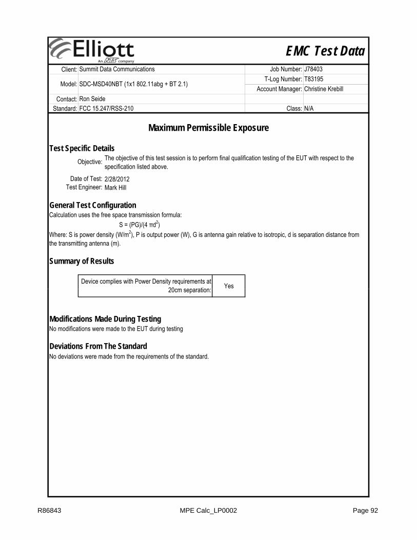
EMC Test DataClient:
Contact:Standard:
Test Specific Details
General Test Configuration
YesDevice complies with Power Density requirements at 20cm separation:
Test Engineer: Mark Hill
Calculation uses the free space transmission formula: S = (PG)/(4 πd2)Where: S is power density (W/m2), P is output power (W), G is antenna gain relative to isotropic, d is separation distance from the transmitting antenna (m).
Summary of Results
Maximum Permissible Exposure
Objective: The objective of this test session is to perform final qualification testing of the EUT with respect to the specification listed above.
Date of Test: 2/28/2012
Ron SeideFCC 15.247/RSS-210 Class: N/A
Summit Data Communications Job Number: J78403
Model: SDC-MSD40NBT (1x1 802.11abg + BT 2.1)T-Log Number: T83195
Account Manager: Christine Krebill
20cm separation:
Modifications Made During TestingNo modifications were made to the EUT during testing
Deviations From The StandardNo deviations were made from the requirements of the standard.
R86843 MPE Calc_LP0002 Page 92
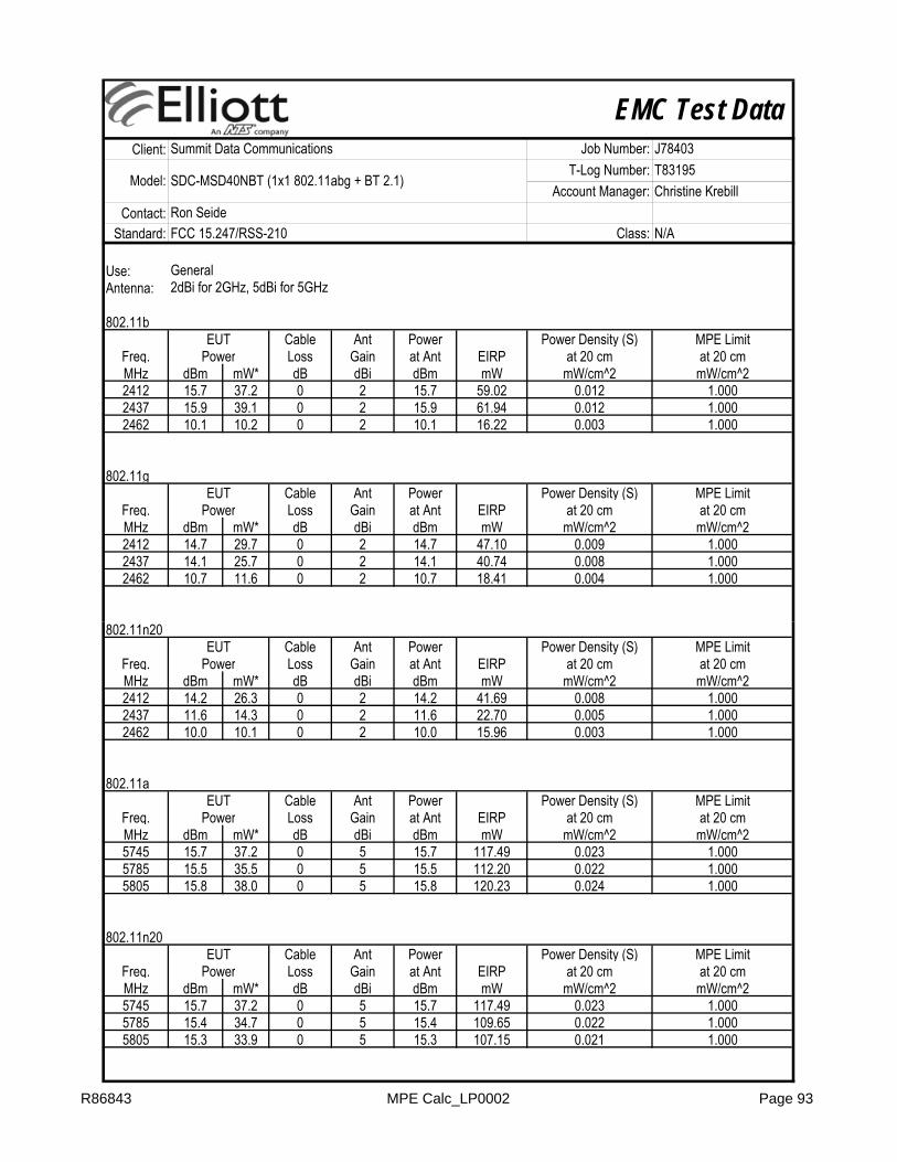
EMC Test DataClient:
Contact:Standard:
Ron SeideFCC 15.247/RSS-210 Class: N/A
Summit Data Communications Job Number: J78403
Model: SDC-MSD40NBT (1x1 802.11abg + BT 2.1)T-Log Number: T83195
Account Manager: Christine Krebill
Use: GeneralAntenna: 2dBi for 2GHz, 5dBi for 5GHz
802.11bCable Ant Power
Freq. Loss Gain at Ant EIRPMHz dBm mW* dB dBi dBm mW2412 15.7 37.2 0 2 15.7 59.022437 15.9 39.1 0 2 15.9 61.942462 10.1 10.2 0 2 10.1 16.22
802.11gCable Ant Power
Freq. Loss Gain at Ant EIRPMHz dBm mW* dB dBi dBm mW2412 14.7 29.7 0 2 14.7 47.102437 14.1 25.7 0 2 14.1 40.742462 10.7 11.6 0 2 10.7 18.41
0.008 1.0000.004 1.000
Power at 20 cm at 20 cmmW/cm^2 mW/cm^2
0.009 1.000
0.012 1.0000.003 1.000
EUT Power Density (S) MPE Limit
Power at 20 cm at 20 cmmW/cm^2 mW/cm^2
0.012 1.000
EUT Power Density (S) MPE Limit
802.11n20Cable Ant Power
Freq. Loss Gain at Ant EIRPMHz dBm mW* dB dBi dBm mW2412 14.2 26.3 0 2 14.2 41.692437 11.6 14.3 0 2 11.6 22.702462 10.0 10.1 0 2 10.0 15.96
802.11aCable Ant Power
Freq. Loss Gain at Ant EIRPMHz dBm mW* dB dBi dBm mW5745 15.7 37.2 0 5 15.7 117.495785 15.5 35.5 0 5 15.5 112.205805 15.8 38.0 0 5 15.8 120.23
802.11n20Cable Ant Power
Freq. Loss Gain at Ant EIRPMHz dBm mW* dB dBi dBm mW5745 15.7 37.2 0 5 15.7 117.495785 15.4 34.7 0 5 15.4 109.655805 15.3 33.9 0 5 15.3 107.15
0.022 1.0000.021 1.000
Power at 20 cm at 20 cmmW/cm^2 mW/cm^2
0.023 1.000
0.022 1.0000.024 1.000
EUT Power Density (S) MPE Limit
Power at 20 cm at 20 cmmW/cm^2 mW/cm^2
0.023 1.000
0.005 1.0000.003 1.000
EUT Power Density (S) MPE Limit
Power at 20 cm at 20 cmmW/cm^2 mW/cm^2
0.008 1.000
EUT Power Density (S) MPE Limit
R86843 MPE Calc_LP0002 Page 93

EMC Test DataClient:
Contact:Standard:
Ron SeideFCC 15.247/RSS-210 Class: N/A
Summit Data Communications Job Number: J78403
Model: SDC-MSD40NBT (1x1 802.11abg + BT 2.1)T-Log Number: T83195
Account Manager: Christine Krebill
UNII Bands802.11a
Cable Ant PowerFreq. Loss Gain at Ant EIRPMHz dBm mW* dB dBi dBm mW5260 12.8 19.0 0 5 12.8 60.125300 14.2 26.0 0 5 14.2 82.225320 10.5 11.2 0 5 10.5 35.485500 15.0 31.3 0 5 15.0 99.085580 13.5 22.3 0 5 13.5 70.475700 8.1 6.4 0 5 8.1 20.28
802.11n20Cable Ant Power
Freq. Loss Gain at Ant EIRPMHz dBm mW* dB dBi dBm mW5260 11.9 15.6 0 5 11.9 49.435300 13.2 20.7 0 5 13.2 65.615320 8.5 7.1 0 5 8.5 22.395500 13.2 20.9 0 5 13.2 66.07
0.013 1.0000.004 1.0000.013 1.000
0.010 1.000
Power at 20 cm at 20 cmmW/cm^2 mW/cm^2
0.014 1.0000.004 1.000
EUT Power Density (S) MPE Limit
0.016 1.0000.007 1.0000.020 1.000
0.012 1.000
Power at 20 cm at 20 cmmW/cm^2 mW/cm^2
EUT Power Density (S) MPE Limit
5580 12.6 18.2 0 5 12.6 57.545700 10.7 11.7 0 5 10.7 37.07
0.011 1.0000.007 1.000
R86843 MPE Calc_LP0002 Page 94

EMC Test Data
Emissions Standard(s): FCC 15.E/RSS-210
Christine KrebillModel: SDC-MSD40NBT (1x1 802.11abg + BT 2.1)
Account Manager:
Immunity Standard(s): - Environment: -
Contact: Ron SeideClass: -
-
EMC Test DataFor The
Summit Data Communications
SDC-MSD40NBT (1x1 802.11abg + BT 2.1)
Model
Client: Summit Data Communications Job Number: J78403T-Log Number: T83196
Date of Last Test: 1/6/2012
R86843 Cover Page 95
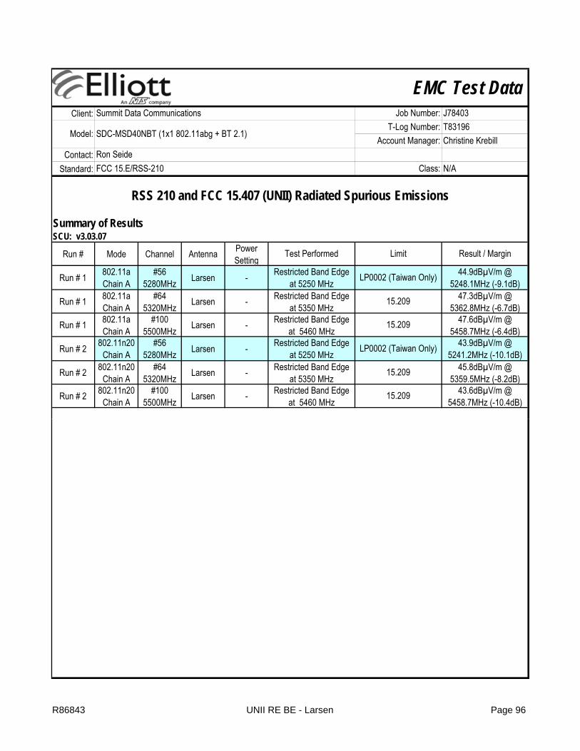
EMC Test DataClient:
Contact:Standard:
Summary of ResultsSCU: v3.03.07
Run # Mode Channel Antenna Power Setting
Run # 1 802.11a Chain A
#56 5280MHz Larsen -
Run # 1 802.11aChain A
#64 5320MHz Larsen -
Run # 1 802.11aChain A
#100 5500MHz Larsen -
Run # 2 802.11n20 Chain A
#56 5280MHz Larsen -
Run # 2 802.11n20Chain A
#64 5320MHz Larsen -
Run # 2 802.11n20Chain A
#100 5500MHz Larsen -
Summit Data Communications Job Number: J78403
Model: SDC-MSD40NBT (1x1 802.11abg + BT 2.1)T-Log Number: T83196
Account Manager: Christine KrebillRon SeideFCC 15.E/RSS-210 Class: N/A
Restricted Band Edge at 5250 MHz LP0002 (Taiwan Only) 44.9dBµV/m @
5248.1MHz (-9.1dB)
RSS 210 and FCC 15.407 (UNII) Radiated Spurious Emissions
Test Performed Limit Result / Margin
45.8dBµV/m @ 5359.5MHz (-8.2dB)
47.6dBµV/m @ 5458.7MHz (-6.4dB)
Restricted Band Edge at 5350 MHz
15.209 47.3dBµV/m @ 5362.8MHz (-6.7dB)
15.209Restricted Band Edge at 5460 MHz
Restricted Band Edge at 5460 MHz
15.209 43.6dBµV/m @ 5458.7MHz (-10.4dB)
Restricted Band Edge at 5250 MHz LP0002 (Taiwan Only) 43.9dBµV/m @
5241.2MHz (-10.1dB)Restricted Band Edge
at 5350 MHz15.209
R86843 UNII RE BE - Larsen Page 96
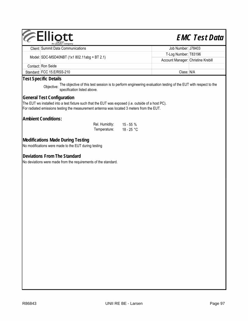
EMC Test DataClient:
Contact:Standard:
Summit Data Communications Job Number: J78403
Model: SDC-MSD40NBT (1x1 802.11abg + BT 2.1)T-Log Number: T83196
Account Manager: Christine KrebillRon SeideFCC 15.E/RSS-210 Class: N/A
Test Specific Details
General Test Configuration
Ambient Conditions:15 - 55 %18 - 25 °C
Objective: The objective of this test session is to perform engineering evaluation testing of the EUT with respect to the specification listed above.
Modifications Made During TestingNo modifications were made to the EUT during testing
Deviations From The StandardNo deviations were made from the requirements of the standard.
The EUT ws installed into a test fixture such that the EUT was exposed (i.e. outside of a host PC).For radiated emissions testing the measurement antenna was located 3 meters from the EUT.
Rel. Humidity:Temperature:
R86843 UNII RE BE - Larsen Page 97
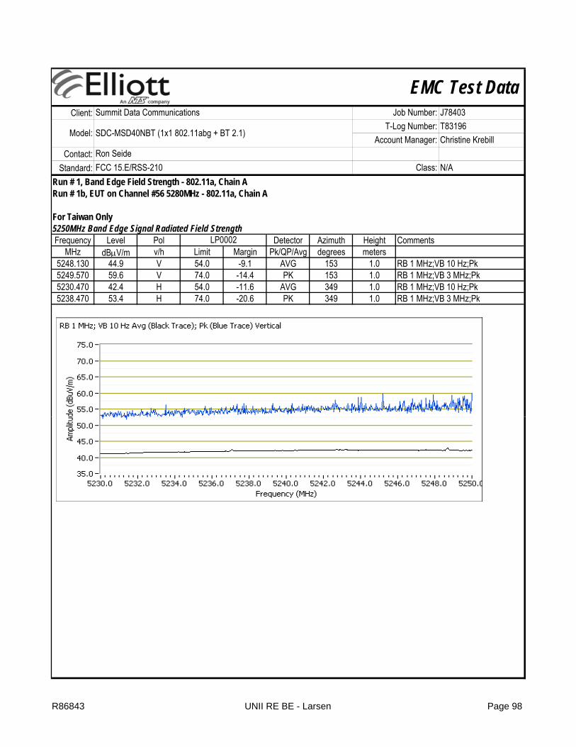
EMC Test DataClient:
Contact:Standard:
Summit Data Communications Job Number: J78403
Model: SDC-MSD40NBT (1x1 802.11abg + BT 2.1)T-Log Number: T83196
Account Manager: Christine KrebillRon SeideFCC 15.E/RSS-210 Class: N/A
Run # 1, Band Edge Field Strength - 802.11a, Chain ARun # 1b, EUT on Channel #56 5280MHz - 802.11a, Chain A
For Taiwan Only5250MHz Band Edge Signal Radiated Field StrengthFrequency Level Pol Detector Azimuth Height Comments
MHz dBμV/m v/h Limit Margin Pk/QP/Avg degrees meters5248.130 44.9 V 54.0 -9.1 AVG 153 1.0 RB 1 MHz;VB 10 Hz;Pk5249.570 59.6 V 74.0 -14.4 PK 153 1.0 RB 1 MHz;VB 3 MHz;Pk5230.470 42.4 H 54.0 -11.6 AVG 349 1.0 RB 1 MHz;VB 10 Hz;Pk5238.470 53.4 H 74.0 -20.6 PK 349 1.0 RB 1 MHz;VB 3 MHz;Pk
LP0002
R86843 UNII RE BE - Larsen Page 98

EMC Test DataClient:
Contact:Standard:
Summit Data Communications Job Number: J78403
Model: SDC-MSD40NBT (1x1 802.11abg + BT 2.1)T-Log Number: T83196
Account Manager: Christine KrebillRon SeideFCC 15.E/RSS-210 Class: N/A
Run # 1c, EUT on Channel #64 5320MHz - 802.11a, Chain A
Direct Measurement of Field Strength at the bandedgeFrequency Level Pol Detector Azimuth Height Comments
MHz dBμV/m v/h Limit Margin Pk/QP/Avg degrees meters5362.830 47.3 V 54.0 -6.7 AVG 155 1.0 RB 1 MHz;VB 10 Hz;Pk5363.500 58.4 V 74.0 -15.6 PK 155 1.0 RB 1 MHz;VB 3 MHz;Pk5364.670 43.5 H 54.0 -10.5 AVG 146 1.0 RB 1 MHz;VB 10 Hz;Pk5358.630 55.6 H 74.0 -18.4 PK 146 1.0 RB 1 MHz;VB 3 MHz;Pk
Test Engineer: Rafael Varelas Config Change: NoneDate of Test: 12/28/2011 Test Location: FT Chamber #4
15.209 / 15.247
R86843 UNII RE BE - Larsen Page 99

EMC Test DataClient:
Contact:Standard:
Summit Data Communications Job Number: J78403
Model: SDC-MSD40NBT (1x1 802.11abg + BT 2.1)T-Log Number: T83196
Account Manager: Christine KrebillRon SeideFCC 15.E/RSS-210 Class: N/A
Run # 1d, EUT on Channel #100 5500MHz - 802.11a, Chain A
Direct Measurement of Field Strength at the bandedge @ 5460 MHzFrequency Level Pol Detector Azimuth Height Comments
MHz dBμV/m v/h Limit Margin Pk/QP/Avg degrees meters5458.670 47.6 V 54.0 -6.4 AVG 190 1.0 RB 1 MHz;VB 10 Hz;Pk5458.200 60.7 V 74.0 -13.3 PK 190 1.0 RB 1 MHz;VB 3 MHz;Pk5455.200 43.6 H 54.0 -10.4 AVG 89 1.1 RB 1 MHz;VB 10 Hz;Pk5456.870 55.0 H 74.0 -19.0 PK 89 1.1 RB 1 MHz;VB 3 MHz;Pk
15.209 / 15.247
R86843 UNII RE BE - Larsen Page 100
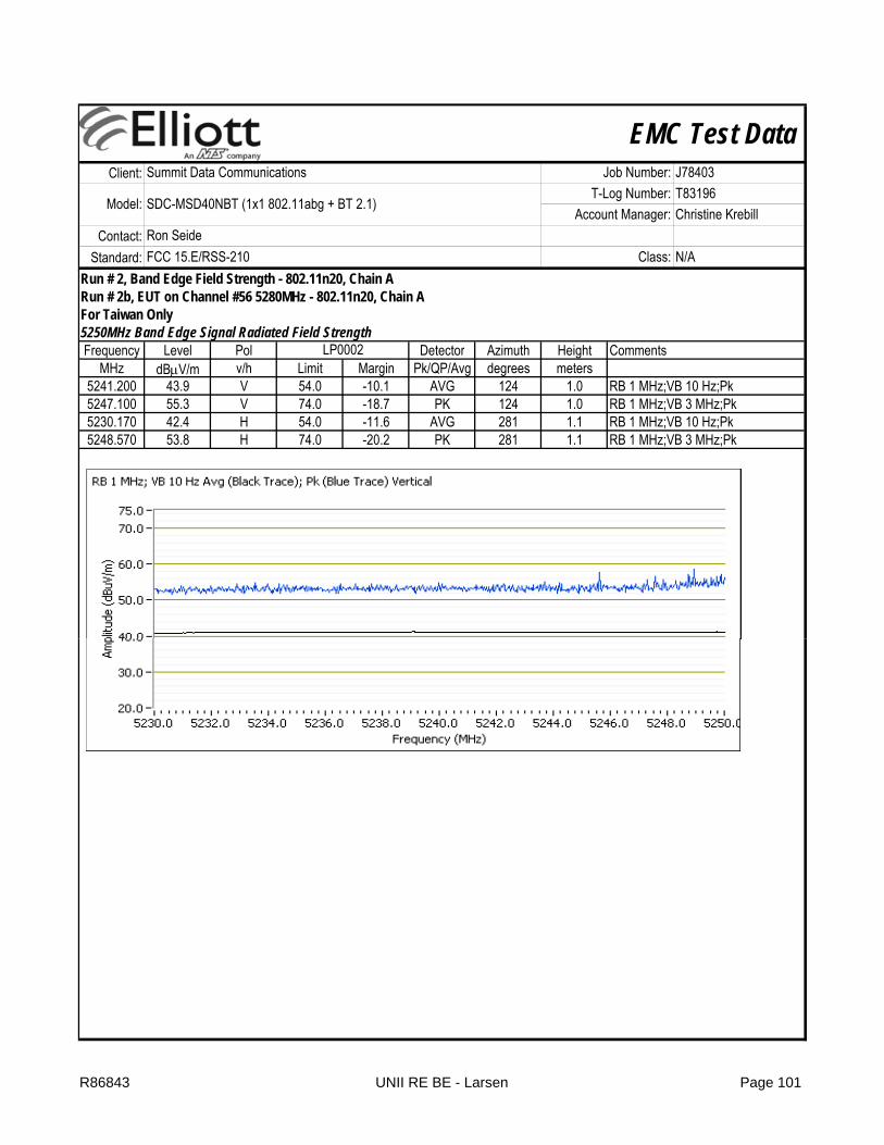
EMC Test DataClient:
Contact:Standard:
Summit Data Communications Job Number: J78403
Model: SDC-MSD40NBT (1x1 802.11abg + BT 2.1)T-Log Number: T83196
Account Manager: Christine KrebillRon SeideFCC 15.E/RSS-210 Class: N/A
Run # 2, Band Edge Field Strength - 802.11n20, Chain ARun # 2b, EUT on Channel #56 5280MHz - 802.11n20, Chain AFor Taiwan Only5250MHz Band Edge Signal Radiated Field StrengthFrequency Level Pol Detector Azimuth Height Comments
MHz dBμV/m v/h Limit Margin Pk/QP/Avg degrees meters5241.200 43.9 V 54.0 -10.1 AVG 124 1.0 RB 1 MHz;VB 10 Hz;Pk5247.100 55.3 V 74.0 -18.7 PK 124 1.0 RB 1 MHz;VB 3 MHz;Pk5230.170 42.4 H 54.0 -11.6 AVG 281 1.1 RB 1 MHz;VB 10 Hz;Pk5248.570 53.8 H 74.0 -20.2 PK 281 1.1 RB 1 MHz;VB 3 MHz;Pk
LP0002
R86843 UNII RE BE - Larsen Page 101

EMC Test DataClient:
Contact:Standard:
Summit Data Communications Job Number: J78403
Model: SDC-MSD40NBT (1x1 802.11abg + BT 2.1)T-Log Number: T83196
Account Manager: Christine KrebillRon SeideFCC 15.E/RSS-210 Class: N/A
Run # 2c, EUT on Channel #64 5320MHz - 802.11n20, Chain A
Direct Measurement of Field Strength at the bandedgeFrequency Level Pol Detector Azimuth Height Comments
MHz dBμV/m v/h Limit Margin Pk/QP/Avg degrees meters5359.500 45.8 V 54.0 -8.2 AVG 189 1.0 RB 1 MHz;VB 10 Hz;Pk5354.830 56.2 V 74.0 -17.8 PK 189 1.0 RB 1 MHz;VB 3 MHz;Pk5358.670 43.2 H 54.0 -10.8 AVG 107 1.0 RB 1 MHz;VB 10 Hz;Pk5355.070 54.6 H 74.0 -19.4 PK 107 1.0 RB 1 MHz;VB 3 MHz;Pk
Date of Test: 12/28/2011 Test Location:
15.209 / 15.247
FT Chamber #4Test Engineer: Rafael Varelas Config Change: None
R86843 UNII RE BE - Larsen Page 102

EMC Test DataClient:
Contact:Standard:
Summit Data Communications Job Number: J78403
Model: SDC-MSD40NBT (1x1 802.11abg + BT 2.1)T-Log Number: T83196
Account Manager: Christine KrebillRon SeideFCC 15.E/RSS-210 Class: N/A
Run # 2d, EUT on Channel #100, 5500MHz - 802.11n20, Chain A
Direct Measurement of Field Strength at the bandedge @ 5460 MHzFrequency Level Pol Detector Azimuth Height Comments
MHz dBμV/m v/h Limit Margin Pk/QP/Avg degrees meters5458.700 43.6 V 54.0 -10.4 AVG 89 1.0 RB 1 MHz;VB 10 Hz;Pk5441.200 54.4 V 74.0 -19.6 PK 89 1.0 RB 1 MHz;VB 3 MHz;Pk5457.570 43.6 H 54.0 -10.4 AVG 142 1.0 RB 1 MHz;VB 10 Hz;Pk5443.130 54.9 H 74.0 -19.1 PK 142 1.0 RB 1 MHz;VB 3 MHz;Pk
15.209 / 15.247
R86843 UNII RE BE - Larsen Page 103

EMC Test DataClient:
Contact:Standard:
Summary of ResultsSCU: v3.03.07
Run # Mode Channel Antenna Power Setting
802.11a Chain A
#60 5300MHz Larsen -
n20 Chain A
#60 5300MHz Larsen -
#52 5260MHz Larsen -
#645320MHz Larsen -
802.11a Chain A
#1165580MHz Larsen -
n20 Chain A
#1165580MHz Larsen -
Summit Data Communications Job Number: J78403
Model: SDC-MSD40NBT (1x1 802.11abg + BT 2.1)T-Log Number: T83196
Account Manager: Christine Krebill
RSS 210 and FCC 15.407 (UNII) Radiated Spurious Emissions
Test Performed Limit Result / Margin
Ron SeideFCC 15.E/RSS-210 Class: N/A
Run #2(5250-
5350MHz Band)
Radiated Emissions,1 - 40 GHz FCC 15.209 / 15 E
40.3dBµV/m @ 1345.6MHz (-13.7dB)
39.4dBµV/m @ 1345.5MHz (-14.6dB)
Worst case mode/worse case Chain A top and bottom channels.
802.11a Chain A
Radiated Emissions,1 - 40 GHz FCC 15.209 / 15 E
40.8dBµV/m @ 1306.5MHz (-13.2dB)
40.7dBµV/m @ 1306.5MHz (-13.3dB)
Run #3(5470
Radiated Emissions,1 - 40 GHz FCC 15.209 / 15 E
42.4dBµV/m @ 3720.1MHz (-11.6dB)
41.3dBµV/m @ 3720.0MHz (-12.7dB)
#100 5500MHz Larsen -
#1405700MHz Larsen -
#60 5300MHz Larsen -
#116 5580MHz Larsen -
Test Specific Details
General Test Configuration
Ambient Conditions:15 - 55 %18 - 25 °C
Receive
Radiated Emissions,1 - 18 GHz
RSS 210
41.7dBµV/m @ 3800.1MHz (-12.3dB)
(5470-5725MHz
Band)
( )Worst case mode/worse case Chain A top and bottom channels.
802.11a Chain A
Radiated Emissions,1 - 40 GHz FCC 15.209 / 15 E
42.3dBµV/m @ 3666.7MHz (-11.7dB)
Objective: The objective of this test session is to perform engineering evaluation testing of the EUT with respect to the specification listed above.
The EUT ws installed into a test fixture such that the EUT was exposed (i.e. outside of a host PC).For radiated emissions testing the measurement antenna was located 3 meters from the EUT.
Radiated Emissions,1 - 18 GHz
RSS 210 44.1dBµV/m @ 1306.5MHz (-9.9dB)
44.4dBµV/m @ 1345.5MHz (-9.6dB)Run #4
Rel. Humidity:Temperature:
R86843 UNII RE - Larsen Page 104

EMC Test DataClient:
Contact:Standard:
Summit Data Communications Job Number: J78403
Model: SDC-MSD40NBT (1x1 802.11abg + BT 2.1)T-Log Number: T83196
Account Manager: Christine KrebillRon SeideFCC 15.E/RSS-210 Class: N/A
Deviations From The StandardNo deviations were made from the requirements of the standard.
Modifications Made During TestingNo modifications were made to the EUT during testing
R86843 UNII RE - Larsen Page 105
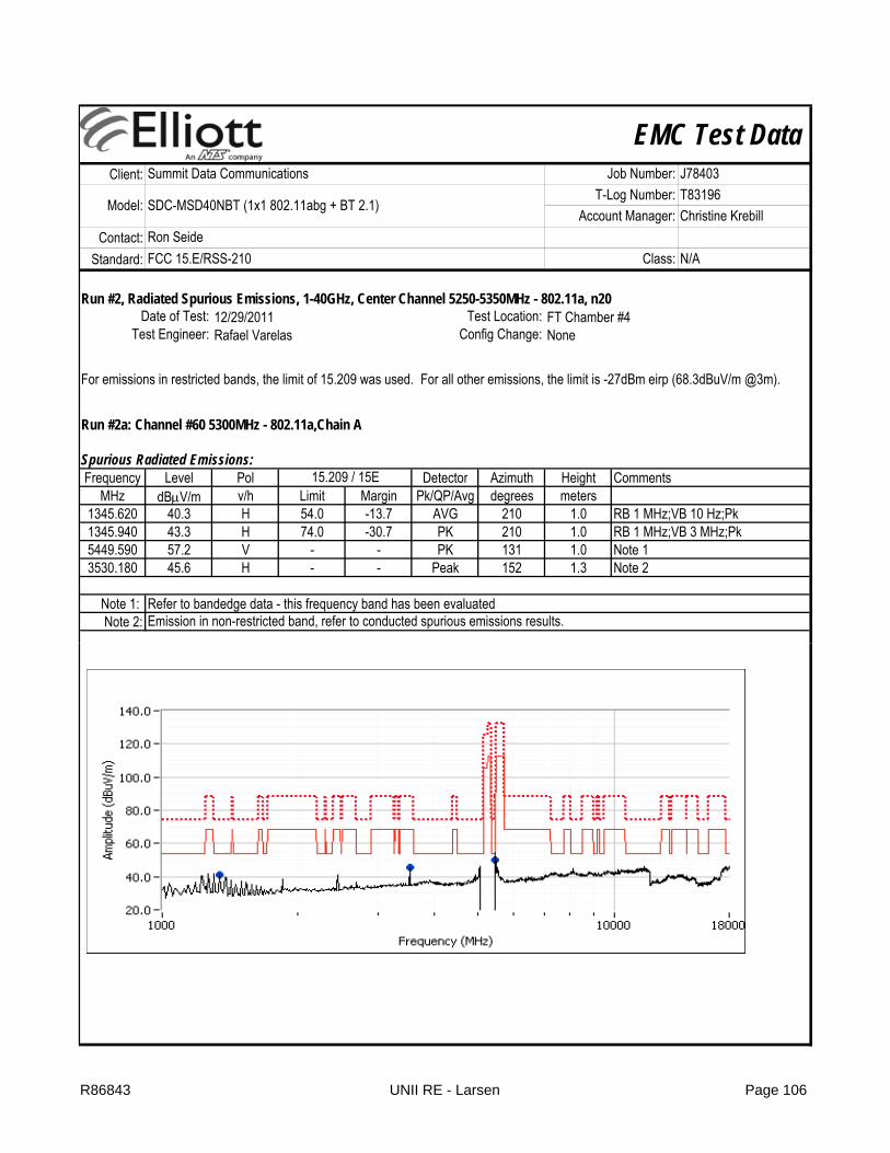
EMC Test DataClient:
Contact:Standard:
Summit Data Communications Job Number: J78403
Model: SDC-MSD40NBT (1x1 802.11abg + BT 2.1)T-Log Number: T83196
Account Manager: Christine KrebillRon SeideFCC 15.E/RSS-210 Class: N/A
Run #2, Radiated Spurious Emissions, 1-40GHz, Center Channel 5250-5350MHz - 802.11a, n20
Run #2a: Channel #60 5300MHz - 802.11a,Chain A
Spurious Radiated Emissions:Frequency Level Pol Detector Azimuth Height Comments
MHz dBμV/m v/h Limit Margin Pk/QP/Avg degrees meters1345.620 40.3 H 54.0 -13.7 AVG 210 1.0 RB 1 MHz;VB 10 Hz;Pk1345.940 43.3 H 74.0 -30.7 PK 210 1.0 RB 1 MHz;VB 3 MHz;Pk5449.590 57.2 V - - PK 131 1.0 Note 13530.180 45.6 H - - Peak 152 1.3 Note 2
Note 1: Refer to bandedge data - this frequency band has been evaluatedNote 2:
Config Change: NoneDate of Test: 12/29/2011 Test Location: FT Chamber #4
15.209 / 15E
Emission in non-restricted band, refer to conducted spurious emissions results.
For emissions in restricted bands, the limit of 15.209 was used. For all other emissions, the limit is -27dBm eirp (68.3dBuV/m @3m).
Test Engineer: Rafael Varelas
R86843 UNII RE - Larsen Page 106

EMC Test DataClient:
Contact:Standard:
Summit Data Communications Job Number: J78403
Model: SDC-MSD40NBT (1x1 802.11abg + BT 2.1)T-Log Number: T83196
Account Manager: Christine KrebillRon SeideFCC 15.E/RSS-210 Class: N/A
Run #2b: Channel #60 5300MHz - 802.11n20,Chain A
Spurious Radiated Emissions:Frequency Level Pol Detector Azimuth Height Comments
MHz dBμV/m v/h Limit Margin Pk/QP/Avg degrees meters1345.500 39.4 H 54.0 -14.6 AVG 273 1.0 RB 1 MHz;VB 10 Hz;Pk1345.280 43.1 H 74.0 -30.9 PK 273 1.0 RB 1 MHz;VB 3 MHz;Pk5457.860 50.7 V - - Peak 157 1.3 Note 13533.390 45.6 H - - Peak 10 1.6 Note 2
Note 1: Refer to bandedge data - this frequency band has been evaluatedNote 2:
15.209 / 15E
Emission in non-restricted band, refer to conducted spurious emissions results.
R86843 UNII RE - Larsen Page 107

EMC Test DataClient:
Contact:Standard:
Summit Data Communications Job Number: J78403
Model: SDC-MSD40NBT (1x1 802.11abg + BT 2.1)T-Log Number: T83196
Account Manager: Christine KrebillRon SeideFCC 15.E/RSS-210 Class: N/A
Run #2c: Channel #52 5260MHz - 802.11a
Spurious Radiated Emissions:Frequency Level Pol Detector Azimuth Height Comments
MHz dBμV/m v/h Limit Margin Pk/QP/Avg degrees meters1306.520 40.8 H 54.0 -13.2 AVG 203 1.0 RB 1 MHz;VB 10 Hz;Pk1306.450 44.0 H 74.0 -30.0 PK 203 1.0 RB 1 MHz;VB 3 MHz;Pk3506.800 46.2 H - - Peak 12 1.6 Note 1
Note 1:
15.209 / 15E
Emission in non-restricted band, refer to conducted spurious emissions results.
R86843 UNII RE - Larsen Page 108

EMC Test DataClient:
Contact:Standard:
Summit Data Communications Job Number: J78403
Model: SDC-MSD40NBT (1x1 802.11abg + BT 2.1)T-Log Number: T83196
Account Manager: Christine KrebillRon SeideFCC 15.E/RSS-210 Class: N/A
Run #2d: Channel #64 5320MHz - 802.11a
Spurious Radiated Emissions:Frequency Level Pol Detector Azimuth Height Comments
MHz dBμV/m v/h Limit Margin Pk/QP/Avg degrees meters1306.500 40.7 H 54.0 -13.3 AVG 201 1.0 RB 1 MHz;VB 10 Hz;Pk1306.510 43.8 H 74.0 -30.2 PK 201 1.0 RB 1 MHz;VB 3 MHz;Pk3546.770 46.3 H - - Peak 153 1.3 Note 1
Note 1:
15.209 / 15E
Emission in non-restricted band, refer to conducted spurious emissions results.
R86843 UNII RE - Larsen Page 109

EMC Test DataClient:
Contact:Standard:
Summit Data Communications Job Number: J78403
Model: SDC-MSD40NBT (1x1 802.11abg + BT 2.1)T-Log Number: T83196
Account Manager: Christine KrebillRon SeideFCC 15.E/RSS-210 Class: N/A
Run #3, Radiated Spurious Emissions, 1-40GHz, Center Channel 5470-5725MHz - 802.11a, n20
Run #3a: Channel #116 5580MHz - 802.11a,Chain A
Spurious Radiated Emissions:Frequency Level Pol Detector Azimuth Height Comments
MHz dBμV/m v/h Limit Margin Pk/QP/Avg degrees meters3720.060 42.4 H 54.0 -11.6 AVG 323 1.4 RB 1 MHz;VB 10 Hz;Pk3720.090 48.2 H 74.0 -25.8 PK 323 1.4 RB 1 MHz;VB 3 MHz;Pk1306.530 38.8 V 54.0 -15.2 AVG 191 1.0 RB 1 MHz;VB 10 Hz;Pk1306.270 42.8 V 74.0 -31.2 PK 191 1.0 RB 1 MHz;VB 3 MHz;Pk
Rafael Varelas Config Change: NoneDate of Test: 12/29/2011 Test Location: FT Chamber #4
15.209 / 15E
For emissions in restricted bands, the limit of 15.209 was used. For all other emissions, the limit is -27dBm eirp (68.3dBuV/m @3m).
Test Engineer:
R86843 UNII RE - Larsen Page 110
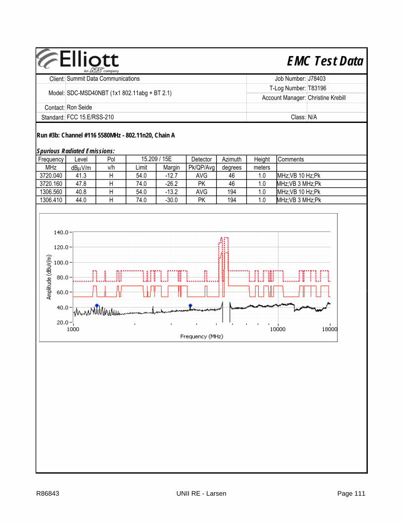
EMC Test DataClient:
Contact:Standard:
Summit Data Communications Job Number: J78403
Model: SDC-MSD40NBT (1x1 802.11abg + BT 2.1)T-Log Number: T83196
Account Manager: Christine KrebillRon SeideFCC 15.E/RSS-210 Class: N/A
Run #3b: Channel #116 5580MHz - 802.11n20, Chain A
Spurious Radiated Emissions:Frequency Level Pol Detector Azimuth Height Comments
MHz dBμV/m v/h Limit Margin Pk/QP/Avg degrees meters3720.040 41.3 H 54.0 -12.7 AVG 46 1.0 MHz;VB 10 Hz;Pk3720.160 47.8 H 74.0 -26.2 PK 46 1.0 MHz;VB 3 MHz;Pk1306.560 40.8 H 54.0 -13.2 AVG 194 1.0 MHz;VB 10 Hz;Pk1306.410 44.0 H 74.0 -30.0 PK 194 1.0 MHz;VB 3 MHz;Pk
15.209 / 15E
R86843 UNII RE - Larsen Page 111

EMC Test DataClient:
Contact:Standard:
Summit Data Communications Job Number: J78403
Model: SDC-MSD40NBT (1x1 802.11abg + BT 2.1)T-Log Number: T83196
Account Manager: Christine KrebillRon SeideFCC 15.E/RSS-210 Class: N/A
Run #3c: Channel #100 5500 MHz - 802.11a
Spurious Radiated Emissions:Frequency Level Pol Detector Azimuth Height Comments
MHz dBμV/m v/h Limit Margin Pk/QP/Avg degrees meters3666.710 42.3 H 54.0 -11.7 AVG 323 1.3 RB 1 MHz;VB 10 Hz;Pk3666.840 48.1 H 74.0 -25.9 PK 323 1.3 RB 1 MHz;VB 3 MHz;Pk1306.520 41.0 H 54.0 -13.0 AVG 190 1.0 RB 1 MHz;VB 10 Hz;Pk1306.230 44.6 H 74.0 -29.4 PK 190 1.0 RB 1 MHz;VB 3 MHz;Pk
15.209 / 15E
R86843 UNII RE - Larsen Page 112
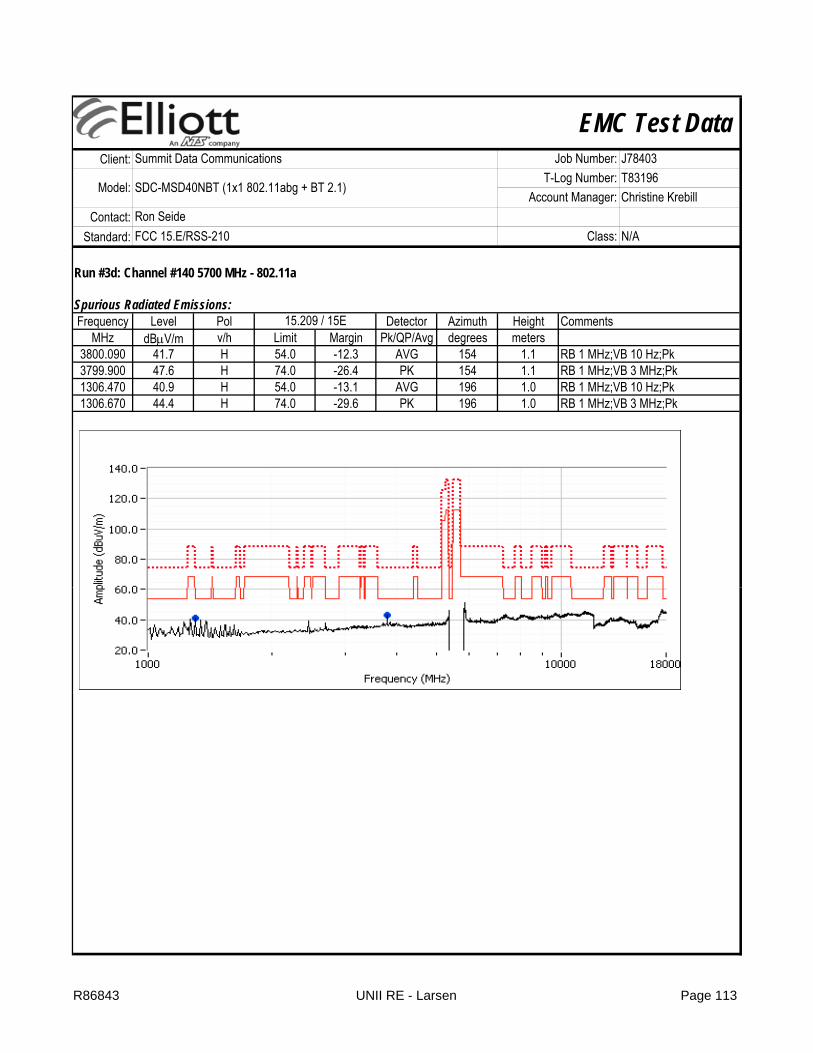
EMC Test DataClient:
Contact:Standard:
Summit Data Communications Job Number: J78403
Model: SDC-MSD40NBT (1x1 802.11abg + BT 2.1)T-Log Number: T83196
Account Manager: Christine KrebillRon SeideFCC 15.E/RSS-210 Class: N/A
Run #3d: Channel #140 5700 MHz - 802.11a
Spurious Radiated Emissions:Frequency Level Pol Detector Azimuth Height Comments
MHz dBμV/m v/h Limit Margin Pk/QP/Avg degrees meters3800.090 41.7 H 54.0 -12.3 AVG 154 1.1 RB 1 MHz;VB 10 Hz;Pk3799.900 47.6 H 74.0 -26.4 PK 154 1.1 RB 1 MHz;VB 3 MHz;Pk1306.470 40.9 H 54.0 -13.1 AVG 196 1.0 RB 1 MHz;VB 10 Hz;Pk1306.670 44.4 H 74.0 -29.6 PK 196 1.0 RB 1 MHz;VB 3 MHz;Pk
15.209 / 15E
R86843 UNII RE - Larsen Page 113
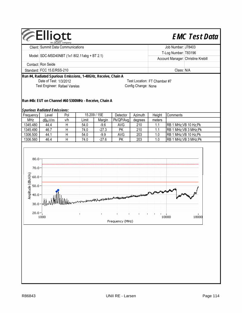
EMC Test DataClient:
Contact:Standard:
Summit Data Communications Job Number: J78403
Model: SDC-MSD40NBT (1x1 802.11abg + BT 2.1)T-Log Number: T83196
Account Manager: Christine KrebillRon SeideFCC 15.E/RSS-210 Class: N/A
Run #4, Radiated Spurious Emissions, 1-40GHz, Receive, Chain A
Run #4b: EUT on Channel #60 5300MHz - Receive, Chain A
Spurious Radiated Emissions:Frequency Level Pol Detector Azimuth Height Comments
MHz dBμV/m v/h Limit Margin Pk/QP/Avg degrees meters1345.480 44.4 H 54.0 -9.6 AVG 210 1.1 RB 1 MHz;VB 10 Hz;Pk1345.490 46.7 H 74.0 -27.3 PK 210 1.1 RB 1 MHz;VB 3 MHz;Pk1306.500 44.1 H 54.0 -9.9 AVG 203 1.0 RB 1 MHz;VB 10 Hz;Pk1306.560 46.4 H 74.0 -27.6 PK 203 1.0 RB 1 MHz;VB 3 MHz;Pk
Config Change: NoneDate of Test: 1/3/2012 Test Location: FT Chamber #7
15.209 / 15E
Test Engineer: Rafael Varelas
R86843 UNII RE - Larsen Page 114

EMC Test DataClient:
Contact:Standard:
Summit Data Communications Job Number: J78403
Model: SDC-MSD40NBT (1x1 802.11abg + BT 2.1)T-Log Number: T83196
Account Manager: Christine KrebillRon SeideFCC 15.E/RSS-210 Class: N/A
Run #4c: EUT on Channel #116 5580MHz - Receive, Chain ASpurious Radiated Emissions:Frequency Level Pol Detector Azimuth Height Comments
MHz dBμV/m v/h Limit Margin Pk/QP/Avg degrees meters1306.480 44.1 H 54.0 -9.9 AVG 206 1.1 RB 1 MHz;VB 10 Hz;Pk1306.480 46.1 H 74.0 -27.9 PK 206 1.1 RB 1 MHz;VB 3 MHz;Pk1345.500 43.9 H 54.0 -10.1 AVG 212 1.0 RB 1 MHz;VB 10 Hz;Pk1345.540 46.1 H 74.0 -27.9 PK 212 1.0 RB 1 MHz;VB 3 MHz;Pk
15.209 / 15E
R86843 UNII RE - Larsen Page 115

EMC Test DataClient:
Contact:Standard:
Test Specific Details
Summary of ResultsNew Module #2011-1296, Laptop #2011-2312, Linux Shell
Pass / Fail
Pass
Pass
1 Power, 5250 - 5350MHz 15.407(a) (1), (2) 802.11a: 26 mW802.11n 20MHz: 21 mW
1 PSD, 5250 - 5350MHz 15.407(a) (1), (2) 802.11a: 3.1 dBm/MHz802.11n 20MHz: 1.7 dBm/MHz
Test Location: FT5 EUT Voltage: 3.3 VDC
Run # Test Performed Limit Result / Margin
Date of Test: 8/24/2011 0:00 Config. Used: 2Test Engineer: John Caizzi / Joseph Cadigal Config Change: no antennas
FCC 15.E/RSS-210 Class: N/A
RSS-210 (LELAN) and FCC 15.407(UNII) Antenna Port Measurements
Power, PSD, Peak Excursion, Bandwidth and Spurious Emissions
Objective: The objective of this test session is to perform final qualification testing of the EUT with respect to the specification listed above.
Model: SDC-MSD40NBT (1x1 802.11abg + BT 2.1)T-Log Number: T83196
Account Manager: Christine Krebill
Summit Data Communications Job Number: J78403
Ron Seide
N/A
Pass
Pass
N/A
1 PSD, 5470 - 5725MHz 15.407(a) (1), (2)802.11a: 4 dBm/MHz802.11n 20MHz: 3.2 dBm/MHz
1 Max EIRP 5470 - 5725MHz
TPC required if EIRP≥ 500mW (27dBm).EIRP ≥ 200mW
(23dBm) DFS threshold = -64dBm.
EIRP = 21.5 dBm (140 mW)TPC not required
1 Max EIRP5250 - 5350MHz
TPC required if EIRP≥ 500mW (27dBm).EIRP ≥ 200mW
(23dBm) DFS threshold = -64dBm.
EIRP = 19.2 dBm (83.2 mW)TPC not required
1 Power, 5470 - 5725MHz 15.407(a) (1), (2)802.11a: 31.6 mW802.11n 20MHz: 21 mW
802.11n 20MHz: 1.7 dBm/MHz
R86843 RF Port Page 116

EMC Test DataClient:
Contact:Standard: FCC 15.E/RSS-210 Class: N/A
Model: SDC-MSD40NBT (1x1 802.11abg + BT 2.1)T-Log Number: T83196
Account Manager: Christine Krebill
Summit Data Communications Job Number: J78403
Ron Seide
Pass / Fail
-
N/A
-
Pass
General Test Configuration
Ambient Conditions:
3 Antenna Conducted - Out of Band Spurious
15.407(b)-27dBm/MHz
All emissions below the -27dBm/MHz limit
When measuring the conducted emissions from the EUT's antenna port, the antenna port of the EUT was connected to the spectrum analyzer or power meter via a suitable attenuator to prevent overloading the measurement system. All measurements are corrected to allow for the external attenuators and cables used.
1 99% Bandwidth RSS 210(Information only)
802.11a: 17.2 MHz802.11n 20MHz: 18 MHz
2 Peak Excursion Envelope 15.407(a) (6)13dB
802.11a: Pass802.11n 20MHz: Pass
Run # Test Performed Limit Result / Margin
1 26dB Bandwidth 15.407(Information only)
> 20MHz for all modes
Temperature: 24 °CRel. Humidity: 43 %
No modifications were made to the EUT during testing
Deviations From The StandardNo deviations were made from the requirements of the standard.
Modifications Made During Testing
R86843 RF Port Page 117
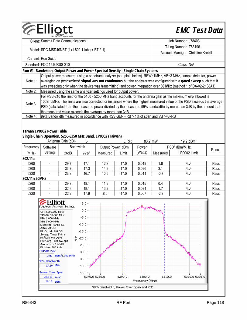
EMC Test DataClient:
Contact:Standard: FCC 15.E/RSS-210 Class: N/A
Model: SDC-MSD40NBT (1x1 802.11abg + BT 2.1)T-Log Number: T83196
Account Manager: Christine Krebill
Summit Data Communications Job Number: J78403
Ron Seide
Run #1: Bandwidth, Output Power and Power Spectral Density - Single Chain Systems
Note 1:
Note 2:
Note 3:
Note 4:
Taiwan LP0002 Power TableSingle Chain Operation, 5250-5350 MHz Band, LP0002 (Taiwan)
5 EIRP: 83.2 mW 19.2 dBmFrequency
(MHz) 26dB 99%4 Measured Limit Measured 802.11a
5260 - 29.7 17.1 12.8 17.0 0.019 1.6 Pass5300 - 33.7 17.3 14.2 17.0 0.026 3.1 Pass
Antenna Gain (dBi):Software Setting
Bandwidth
Output power measured using a spectrum analyzer (see plots below). RBW=1MHz, VB=3 MHz, sample detector, power averaging on (transmitted signal was not continuous but the analyzer was configured with a gated sweep such that it was sweeping only when the device was transmitting) and power integration over 50 MHz (method 1 of DA-02-2138A1).Measured using the same analyzer settings used for output power.For RSS-210 the limit for the 5150 - 5250 MHz band accounts for the antenna gain as the maximum eirp allowed is 10dBm/MHz. The limits are also corrected for instances where the highest measured value of the PSD exceeds the average PSD (calculated from the measured power divided by the measured 99% bandwidth) by more than 3dB by the amount that the measured value exceeds the average by more than 3dB.99% Bandwidth measured in accordance with RSS GEN - RB > 1% of span and VB >=3xRB
ResultLP0002 Limit
4.04.0
Output Power1 dBm Power (Watts)
PSD2 dBm/MHz
5320 - 23.3 16.7 10.5 17.0 0.011 -0.7 Pass802.11n 20MHz
5260 - 29.7 18.1 11.9 17.0 0.015 0.4 Pass5300 - 32.8 18.1 13.2 17.0 0.021 1.7 Pass5320 - 22.2 17.9 8.5 17.0 0.007 -2.8 Pass
4.0
4.04.04.0
R86843 RF Port Page 118

EMC Test DataClient:
Contact:Standard: FCC 15.E/RSS-210 Class: N/A
Model: SDC-MSD40NBT (1x1 802.11abg + BT 2.1)T-Log Number: T83196
Account Manager: Christine Krebill
Summit Data Communications Job Number: J78403
Ron Seide
Single Chain Operation, 5470- 5725 MHz Band5 EIRP: 99.1 mW 20.0 dBm
Frequency(MHz) 26dB 99%4 Measured Limit Measured FCC Limit RSS Limit3
802.11a5500 31.5 17.2 15.0 24.0 0.031 4.0 11.0 11.0 Pass5580 30.5 16.9 13.5 24.0 0.022 2.4 11.0 11.0 Pass5700 25.5 16.6 8.1 24.0 0.006 -2.9 11.0 11.0 Pass
802.11n 20MHz5500 29.5 17.9 13.2 24.0 0.021 2.1 11.0 11.0 Pass5580 28.2 18.0 12.6 24.0 0.018 1.5 11.0 11.0 Pass5700 29.3 18.0 10.7 24.0 0.012 -0.7 11.0 11.0 Pass
Run #2: Peak Excursion(802 11 20) 20MH D i t th i t f th k i
Power (Watts)
PSD2 dBm/MHz Result
Default
Default
Antenna Gain (dBi):Software Setting
Bandwidth Output Power1 dBm
(802.11n20) 20MHz: Device meets the requirement for the peak excursionFreq Freq Freq
(MHz) Value Limit (MHz) Value Limit (MHz) Value Limit5260 11.2 13.0 5500 11.8 13.05300 11.7 13.0 5580 11.2 13.05320 11.8 13.0 5700 11.8 13.0
Note: 802.11n20 represented worse case for peak excursion
Peak Excursion(dB) Peak Excursion(dB) Peak Excursion(dB)
R86843 RF Port Page 119

EMC Test DataClient:
Contact:Standard: FCC 15.E/RSS-210 Class: N/A
Model: SDC-MSD40NBT (1x1 802.11abg + BT 2.1)T-Log Number: T83196
Account Manager: Christine Krebill
Summit Data Communications Job Number: J78403
Ron Seide
Plots Showing Peak ExcursionTrace A: RBW = 1MHz, VBW = 3MHz, Peak hold
Trace B: Same settings as used for power/PSD measurements (RBW = 1 MHz, VBW = 3MHz, Integrated average power)
R86843 RF Port Page 120

EMC Test DataClient:
Contact:Standard: FCC 15.E/RSS-210 Class: N/A
Model: SDC-MSD40NBT (1x1 802.11abg + BT 2.1)T-Log Number: T83196
Account Manager: Christine Krebill
Summit Data Communications Job Number: J78403
Ron Seide
Run #3: Out Of Band Spurious Emissions - Antenna Conducted
Maximum Antenna Gain: 6.5 dBiSpurious Limit: -27.0 dBm/MHz eirp
-33.5 dBm/MHz Average Limit (RB=1MHz, VB=10Hz)-13.5 dBm/MHz Peak Limit (RB=VB=1MHz)
Note 1:
Note 2:Note 3:Note 4:Note 5:
All spurious signals below 1GHz are measured during digital device radiated emissions test.Signals within 10MHz of the 5.725 or 5.825 Band edge are subject to a limit of -17dBm EIRPIf the device is for outdoor use then the -27dBm eirp limit also applies in the 5150 - 5250 MHz band.
The -27dBm/MHz limit is an eirp limit. The limit for antenna port conducted measurements is adjusted to take into consideration the maximum antenna gain (limit = -27dBm - antenna gain). Radiated field strength measurements for signals more than 50MHz from the bands and that are close to the limit are made to determine compliance as the antenna gain is not known at these frequencies.
Signals that fall in the restricted bands of 15.205 are subject to the limit of 15.209.
Plots Showing Out-Of-Band Emissions (RBW=VBW=1MHz)
Limit Used On Plots Note 1:
R86843 RF Port Page 121

EMC Test DataClient:
Contact:Standard: FCC 15.E/RSS-210 Class: N/A
Model: SDC-MSD40NBT (1x1 802.11abg + BT 2.1)T-Log Number: T83196
Account Manager: Christine Krebill
Summit Data Communications Job Number: J78403
Ron Seide
Low channel, 5250 - 5350 MHz Band
Center channel, 5250 - 5350 MHz Band
R86843 RF Port Page 122
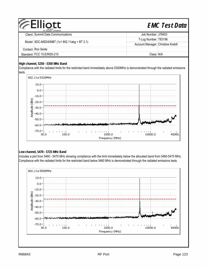
EMC Test DataClient:
Contact:Standard: FCC 15.E/RSS-210 Class: N/A
Model: SDC-MSD40NBT (1x1 802.11abg + BT 2.1)T-Log Number: T83196
Account Manager: Christine Krebill
Summit Data Communications Job Number: J78403
Ron Seide
High channel, 5250 - 5350 MHz BandCompliance with the radiated limits for the restricted band immediately above 5350MHz is demonstrated through the radiated emissions tests.
Low channel, 5470 - 5725 MHz BandIncludes a plot from 5460 - 5470 MHz showing compliance with the limit immediately below the allocated band from 5460-5470 MHz. Compliance with the radiated limits for the restricted band below 5460 MHz is demonstrated through the radiated emissions tests.
R86843 RF Port Page 123

EMC Test DataClient:
Contact:Standard: FCC 15.E/RSS-210 Class: N/A
Model: SDC-MSD40NBT (1x1 802.11abg + BT 2.1)T-Log Number: T83196
Account Manager: Christine Krebill
Summit Data Communications Job Number: J78403
Ron Seide
R86843 RF Port Page 124
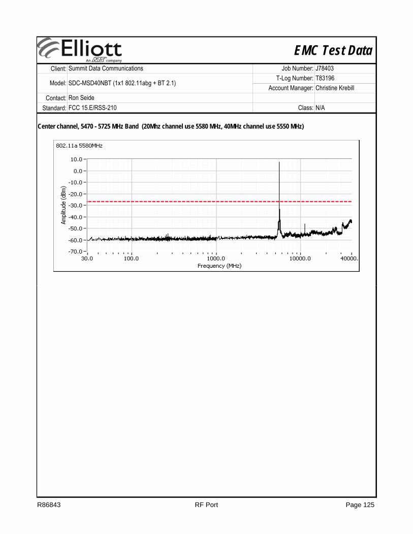
EMC Test DataClient:
Contact:Standard: FCC 15.E/RSS-210 Class: N/A
Model: SDC-MSD40NBT (1x1 802.11abg + BT 2.1)T-Log Number: T83196
Account Manager: Christine Krebill
Summit Data Communications Job Number: J78403
Ron Seide
Center channel, 5470 - 5725 MHz Band (20Mhz channel use 5580 MHz, 40MHz channel use 5550 MHz)
R86843 RF Port Page 125
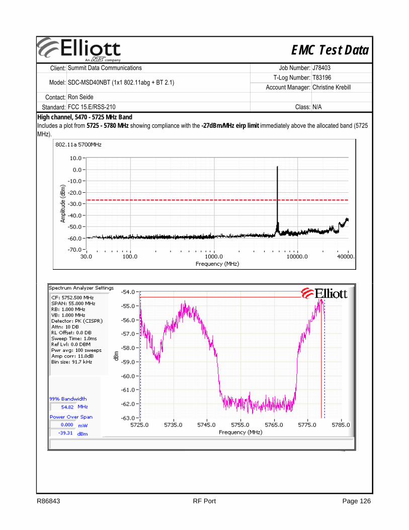
EMC Test DataClient:
Contact:Standard: FCC 15.E/RSS-210 Class: N/A
Model: SDC-MSD40NBT (1x1 802.11abg + BT 2.1)T-Log Number: T83196
Account Manager: Christine Krebill
Summit Data Communications Job Number: J78403
Ron Seide
High channel, 5470 - 5725 MHz BandIncludes a plot from 5725 - 5780 MHz showing compliance with the -27dBm/MHz eirp limit immediately above the allocated band (5725 MHz).
R86843 RF Port Page 126

EMC Test DataClient:
Contact:Standard: FCC 15.E/RSS-210 Class: N/A
Model: SDC-MSD40NBT (1x1 802.11abg + BT 2.1)T-Log Number: T83196
Account Manager: Christine Krebill
Summit Data Communications Job Number: J78403
Ron Seide
802.11n20Low channel, 5250 - 5350 MHz Band
R86843 RF Port Page 127

EMC Test DataClient:
Contact:Standard: FCC 15.E/RSS-210 Class: N/A
Model: SDC-MSD40NBT (1x1 802.11abg + BT 2.1)T-Log Number: T83196
Account Manager: Christine Krebill
Summit Data Communications Job Number: J78403
Ron Seide
Center channel, 5250 - 5350 MHz Band
High channel, 5250 - 5350 MHz BandCompliance with the radiated limits for the restricted band immediately above 5350MHz is demonstrated through the radiated emissions tests.
R86843 RF Port Page 128
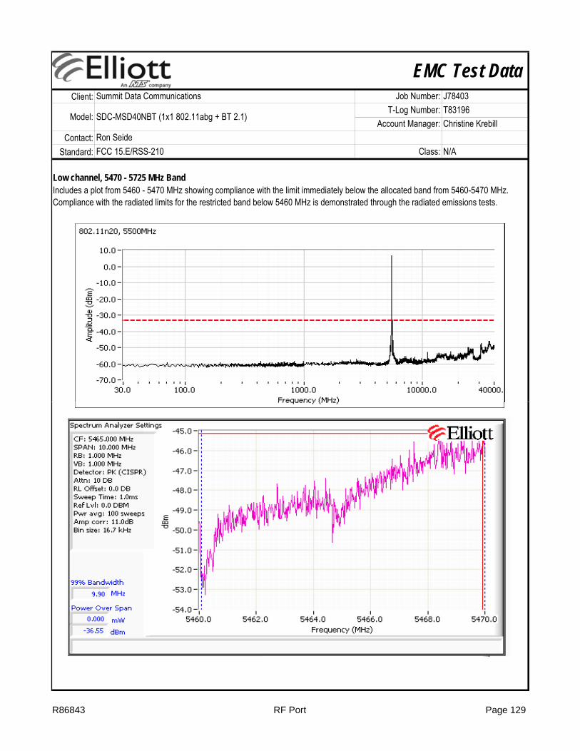
EMC Test DataClient:
Contact:Standard: FCC 15.E/RSS-210 Class: N/A
Model: SDC-MSD40NBT (1x1 802.11abg + BT 2.1)T-Log Number: T83196
Account Manager: Christine Krebill
Summit Data Communications Job Number: J78403
Ron Seide
Low channel, 5470 - 5725 MHz BandIncludes a plot from 5460 - 5470 MHz showing compliance with the limit immediately below the allocated band from 5460-5470 MHz. Compliance with the radiated limits for the restricted band below 5460 MHz is demonstrated through the radiated emissions tests.
R86843 RF Port Page 129

EMC Test DataClient:
Contact:Standard: FCC 15.E/RSS-210 Class: N/A
Model: SDC-MSD40NBT (1x1 802.11abg + BT 2.1)T-Log Number: T83196
Account Manager: Christine Krebill
Summit Data Communications Job Number: J78403
Ron Seide
Center channel, 5470 - 5725 MHz Band (20Mhz channel use 5580 MHz, 40MHz channel use 5550 MHz)
High channel, 5470 - 5725 MHz BandIncludes a plot from 5725 - 5780 MHz showing compliance with the -27dBm/MHz eirp limit immediately above the allocated band (5725 Includes a plot from 5725 - 5780 MHz showing compliance with the -27dBm/MHz eirp limit immediately above the allocated band (5725 MHz).
R86843 RF Port Page 130
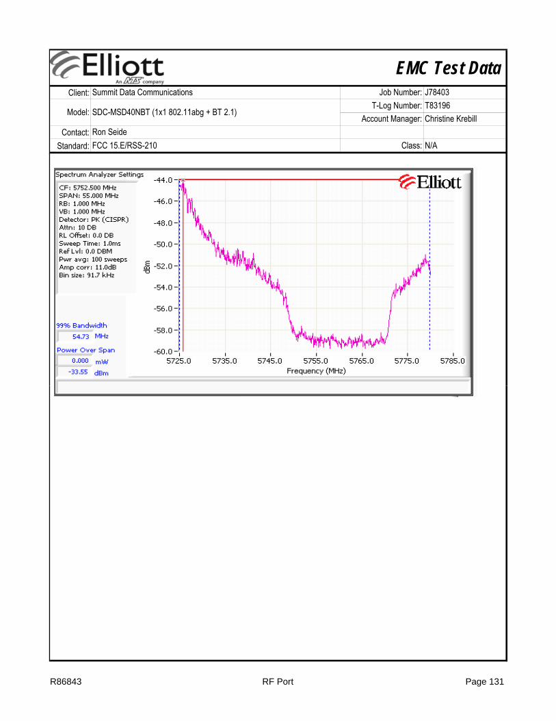
EMC Test DataClient:
Contact:Standard: FCC 15.E/RSS-210 Class: N/A
Model: SDC-MSD40NBT (1x1 802.11abg + BT 2.1)T-Log Number: T83196
Account Manager: Christine Krebill
Summit Data Communications Job Number: J78403
Ron Seide
R86843 RF Port Page 131
EMC Test Data
SDC-WB40 and SDC-MSD40NBT (1x1 802.11abg + BT 2.1)
Model
Contact: Ron Seide -
Immunity Standard(s): EN 301 489-1 V1.8.1 Environment: -
T-Log Number: T83198Account Manager: Christine Krebill
EMC Test DataFor The
Summit Data Communications
Emissions Standard(s): EN 301 489-1 V1.8.1/ FCC Part 15B Class: B
Client: Summit Data Communications Job Number: J78403Model: SDC-WB40 and SDC-MSD40NBT (1x1 802.11abg +
BT 2.1)
Date of Last Test: 12/16/2011
R86843 Cover Page 132

EMC Test DataClient:
Contact:Standard:
Test Specific Details
General Test Configuration
Ambient Conditions: 21 °C33 %Rel. Humidity:
Test Engineer: John Caizzi Config Change: none
For tabletop equipment, the EUT host system was located on a wooden table inside the semi-anechoic chamber, 40 cm from a vertical coupling plane and 80cm from the LISN. The EUT was transmitting on 2437 MHz, 802.11g, 6 Mbps.
Temperature:
Test Location: Fremont Chamber #5 Host Unit Voltage 120V / 60Hz & 230V / 50Hz
Conducted Emissions(Elliott Laboratories Fremont Facility, Semi-Anechoic Chamber)
Objective: The objective of this test session is to perform final qualification testing of the EUT with respect to the specification listed above.
Date of Test: 12/16/2011 Config. Used: 2
Ron SeideEN 301 489-1 V1.8.1/ FCC Part 15B Class: B
Summit Data Communications Job Number: J78403
Model: SDC-WB40 and SDC-MSD40NBT (1x1 802.11abg + BT 2.1)T-Log Number: T83198
Account Manager: Christine Krebill
Summary of Results
ResultPassPass
Deviations From The StandardNo deviations were made from the requirements of the standard.
1 CE, AC Power, 230V/50Hz Class B 31.0dBµV @ 0.687MHz (-15.0dB)
Modifications Made During TestingNo modifications were made to the EUT during testing
2
Run # Test Performed
CE, AC Power,120V/60Hz Class B 31.9dBµV @ 19.501MHz (-18.1dB)
Limit Margin
R86843 CE MSD40 16-Dec-11 Page 133

EMC Test DataClient:
Contact:Standard:
Ron SeideEN 301 489-1 V1.8.1/ FCC Part 15B Class: B
Summit Data Communications Job Number: J78403
Model: SDC-WB40 and SDC-MSD40NBT (1x1 802.11abg + BT 2.1)T-Log Number: T83198
Account Manager: Christine Krebill
Run #1: AC Power Port Conducted Emissions, 0.15 - 30MHz, 230V/50Hz
R86843 CE MSD40 16-Dec-11 Page 134

EMC Test DataClient:
Contact:Standard:
Ron SeideEN 301 489-1 V1.8.1/ FCC Part 15B Class: B
Summit Data Communications Job Number: J78403
Model: SDC-WB40 and SDC-MSD40NBT (1x1 802.11abg + BT 2.1)T-Log Number: T83198
Account Manager: Christine Krebill
Preliminary peak readings captured during pre-scan (peak readings vs. average limit)Frequency Level AC Detector Comments
MHz dBμV Line Limit Margin QP/Ave0.153 53.0 Line 55.8 -2.8 Peak0.163 52.3 Line 55.3 -3.0 Peak0.178 49.8 Line 54.6 -4.8 Peak0.185 49.1 Line 54.3 -5.2 Peak0.195 48.1 Line 53.9 -5.8 Peak0.202 47.6 Line 53.6 -6.0 Peak0.234 45.1 Line 52.3 -7.2 Peak0.250 43.9 Line 51.7 -7.8 Peak0.687 37.0 Line 46.0 -9.0 Peak0.271 41.5 Line 51.1 -9.6 Peak0.464 36.9 Line 46.6 -9.7 Peak0.916 35.9 Line 46.0 -10.1 Peak2.173 35.2 Line 46.0 -10.8 Peak
10.533 35.6 Line 50.0 -14.4 Peak19.501 33.3 Line 50.0 -16.7 Peak0.153 53.7 Neutral 55.8 -2.1 Peak0.167 52.1 Neutral 55.1 -3.0 Peak
Class B
0.185 49.8 Neutral 54.3 -4.5 Peak0.232 46.7 Neutral 52.4 -5.7 Peak0.217 45.8 Neutral 52.9 -7.1 Peak0.255 43.2 Neutral 51.6 -8.4 Peak2.279 36.3 Neutral 46.0 -9.7 Peak0.458 36.6 Neutral 46.7 -10.1 Peak0.685 35.0 Neutral 46.0 -11.0 Peak1.141 34.8 Neutral 46.0 -11.2 Peak
19.502 34.0 Neutral 50.0 -16.0 Peak
R86843 CE MSD40 16-Dec-11 Page 135
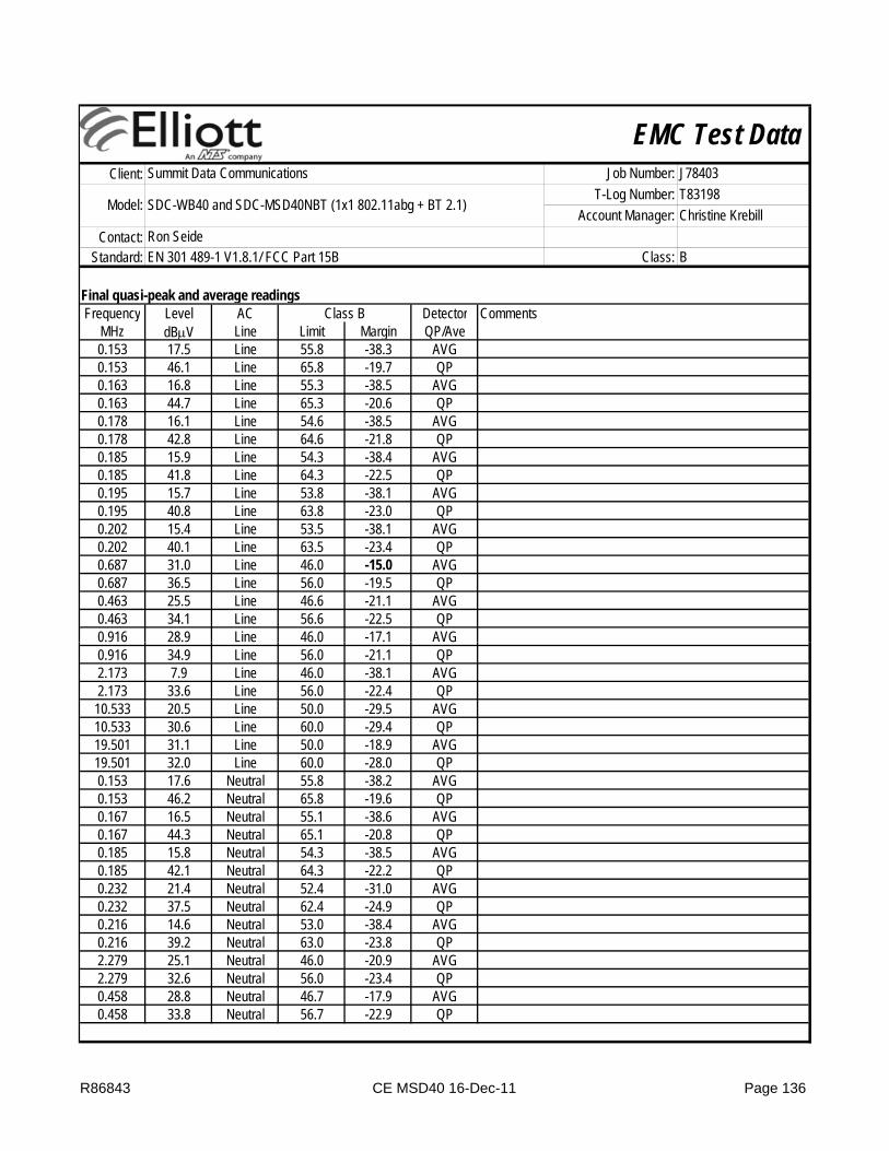
EMC Test DataClient:
Contact:Standard:
Ron SeideEN 301 489-1 V1.8.1/ FCC Part 15B Class: B
Summit Data Communications Job Number: J78403
Model: SDC-WB40 and SDC-MSD40NBT (1x1 802.11abg + BT 2.1)T-Log Number: T83198
Account Manager: Christine Krebill
Final quasi-peak and average readingsFrequency Level AC Detector Comments
MHz dBμV Line Limit Margin QP/Ave0.153 17.5 Line 55.8 -38.3 AVG0.153 46.1 Line 65.8 -19.7 QP0.163 16.8 Line 55.3 -38.5 AVG0.163 44.7 Line 65.3 -20.6 QP0.178 16.1 Line 54.6 -38.5 AVG0.178 42.8 Line 64.6 -21.8 QP0.185 15.9 Line 54.3 -38.4 AVG0.185 41.8 Line 64.3 -22.5 QP0.195 15.7 Line 53.8 -38.1 AVG0.195 40.8 Line 63.8 -23.0 QP0.202 15.4 Line 53.5 -38.1 AVG0.202 40.1 Line 63.5 -23.4 QP0.687 31.0 Line 46.0 -15.0 AVG0.687 36.5 Line 56.0 -19.5 QP0.463 25.5 Line 46.6 -21.1 AVG0.463 34.1 Line 56.6 -22.5 QP0.916 28.9 Line 46.0 -17.1 AVG
Class B
0.916 34.9 Line 56.0 -21.1 QP2.173 7.9 Line 46.0 -38.1 AVG2.173 33.6 Line 56.0 -22.4 QP
10.533 20.5 Line 50.0 -29.5 AVG10.533 30.6 Line 60.0 -29.4 QP19.501 31.1 Line 50.0 -18.9 AVG19.501 32.0 Line 60.0 -28.0 QP0.153 17.6 Neutral 55.8 -38.2 AVG0.153 46.2 Neutral 65.8 -19.6 QP0.167 16.5 Neutral 55.1 -38.6 AVG0.167 44.3 Neutral 65.1 -20.8 QP0.185 15.8 Neutral 54.3 -38.5 AVG0.185 42.1 Neutral 64.3 -22.2 QP0.232 21.4 Neutral 52.4 -31.0 AVG0.232 37.5 Neutral 62.4 -24.9 QP0.216 14.6 Neutral 53.0 -38.4 AVG0.216 39.2 Neutral 63.0 -23.8 QP2.279 25.1 Neutral 46.0 -20.9 AVG2.279 32.6 Neutral 56.0 -23.4 QP0.458 28.8 Neutral 46.7 -17.9 AVG0.458 33.8 Neutral 56.7 -22.9 QP
R86843 CE MSD40 16-Dec-11 Page 136

EMC Test DataClient:
Contact:Standard:
Ron SeideEN 301 489-1 V1.8.1/ FCC Part 15B Class: B
Summit Data Communications Job Number: J78403
Model: SDC-WB40 and SDC-MSD40NBT (1x1 802.11abg + BT 2.1)T-Log Number: T83198
Account Manager: Christine Krebill
Frequency Level AC Detector CommentsMHz dBμV Line Limit Margin QP/Ave0.685 29.4 Neutral 46.0 -16.6 AVG0.685 34.8 Neutral 56.0 -21.2 QP1.141 27.7 Neutral 46.0 -18.3 AVG1.141 34.5 Neutral 56.0 -21.5 QP
19.502 30.2 Neutral 50.0 -19.8 AVG19.502 31.3 Neutral 60.0 -28.7 QP
Class B
R86843 CE MSD40 16-Dec-11 Page 137

EMC Test DataClient:
Contact:Standard:
Ron SeideEN 301 489-1 V1.8.1/ FCC Part 15B Class: B
Summit Data Communications Job Number: J78403
Model: SDC-WB40 and SDC-MSD40NBT (1x1 802.11abg + BT 2.1)T-Log Number: T83198
Account Manager: Christine Krebill
Run #2: AC Power Port Conducted Emissions, 0.15 - 30MHz, 120V/60Hz
R86843 CE MSD40 16-Dec-11 Page 138
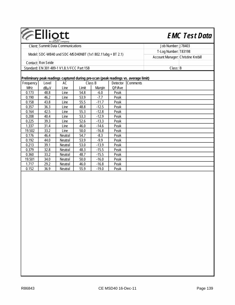
EMC Test DataClient:
Contact:Standard:
Ron SeideEN 301 489-1 V1.8.1/ FCC Part 15B Class: B
Summit Data Communications Job Number: J78403
Model: SDC-WB40 and SDC-MSD40NBT (1x1 802.11abg + BT 2.1)T-Log Number: T83198
Account Manager: Christine Krebill
Preliminary peak readings captured during pre-scan (peak readings vs. average limit)Frequency Level AC Detector Comments
MHz dBμV Line Limit Margin QP/Ave0.173 48.8 Line 54.8 -6.0 Peak0.190 46.2 Line 53.9 -7.7 Peak0.158 43.8 Line 55.5 -11.7 Peak0.357 36.3 Line 48.8 -12.5 Peak0.164 42.5 Line 55.3 -12.8 Peak0.208 40.4 Line 53.3 -12.9 Peak0.225 39.3 Line 52.6 -13.3 Peak1.337 31.4 Line 46.0 -14.6 Peak
19.502 33.2 Line 50.0 -16.8 Peak0.176 46.4 Neutral 54.7 -8.3 Peak0.192 44.0 Neutral 53.9 -9.9 Peak0.213 39.1 Neutral 53.0 -13.9 Peak0.379 32.8 Neutral 48.3 -15.5 Peak0.360 33.2 Neutral 48.7 -15.5 Peak
19.501 34.0 Neutral 50.0 -16.0 Peak1.717 29.2 Neutral 46.0 -16.8 Peak0.152 36.9 Neutral 55.9 -19.0 Peak
Class B
R86843 CE MSD40 16-Dec-11 Page 139
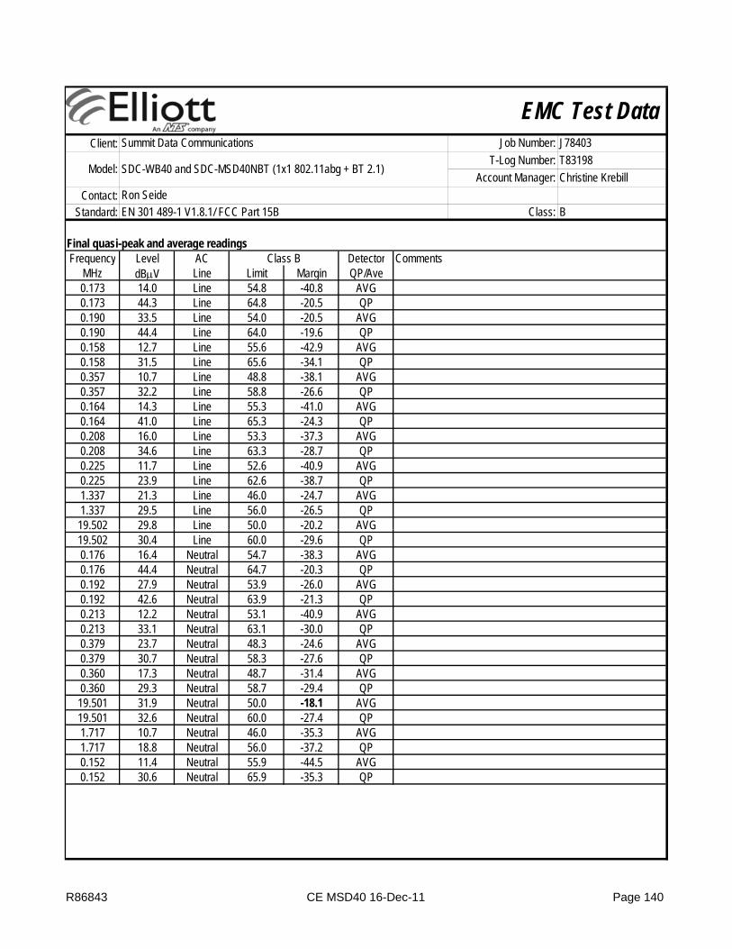
EMC Test DataClient:
Contact:Standard:
Ron SeideEN 301 489-1 V1.8.1/ FCC Part 15B Class: B
Summit Data Communications Job Number: J78403
Model: SDC-WB40 and SDC-MSD40NBT (1x1 802.11abg + BT 2.1)T-Log Number: T83198
Account Manager: Christine Krebill
Final quasi-peak and average readingsFrequency Level AC Detector Comments
MHz dBμV Line Limit Margin QP/Ave0.173 14.0 Line 54.8 -40.8 AVG0.173 44.3 Line 64.8 -20.5 QP0.190 33.5 Line 54.0 -20.5 AVG0.190 44.4 Line 64.0 -19.6 QP0.158 12.7 Line 55.6 -42.9 AVG0.158 31.5 Line 65.6 -34.1 QP0.357 10.7 Line 48.8 -38.1 AVG0.357 32.2 Line 58.8 -26.6 QP0.164 14.3 Line 55.3 -41.0 AVG0.164 41.0 Line 65.3 -24.3 QP0.208 16.0 Line 53.3 -37.3 AVG0.208 34.6 Line 63.3 -28.7 QP0.225 11.7 Line 52.6 -40.9 AVG0.225 23.9 Line 62.6 -38.7 QP1.337 21.3 Line 46.0 -24.7 AVG1.337 29.5 Line 56.0 -26.5 QP
19.502 29.8 Line 50.0 -20.2 AVG
Class B
19.502 30.4 Line 60.0 -29.6 QP0.176 16.4 Neutral 54.7 -38.3 AVG0.176 44.4 Neutral 64.7 -20.3 QP0.192 27.9 Neutral 53.9 -26.0 AVG0.192 42.6 Neutral 63.9 -21.3 QP0.213 12.2 Neutral 53.1 -40.9 AVG0.213 33.1 Neutral 63.1 -30.0 QP0.379 23.7 Neutral 48.3 -24.6 AVG0.379 30.7 Neutral 58.3 -27.6 QP0.360 17.3 Neutral 48.7 -31.4 AVG0.360 29.3 Neutral 58.7 -29.4 QP
19.501 31.9 Neutral 50.0 -18.1 AVG19.501 32.6 Neutral 60.0 -27.4 QP1.717 10.7 Neutral 46.0 -35.3 AVG1.717 18.8 Neutral 56.0 -37.2 QP0.152 11.4 Neutral 55.9 -44.5 AVG0.152 30.6 Neutral 65.9 -35.3 QP
R86843 CE MSD40 16-Dec-11 Page 140

Elliott Laboratories -- EMC Department Test Report Report Date: March 20, 2012
APPENDIX C RADIATED EMISSIONS TEST CONFIGURATION PHOTOGRAPHS
File R86843 Page 141 of 147

Elliott Laboratories -- EMC Department Test Report Report Date: March 20, 2012
APPENDIX D CONDUCTED EMISSIONS TEST CONFIGURATION PHOTOGRAPHS
File R86843 Page 142 of 147
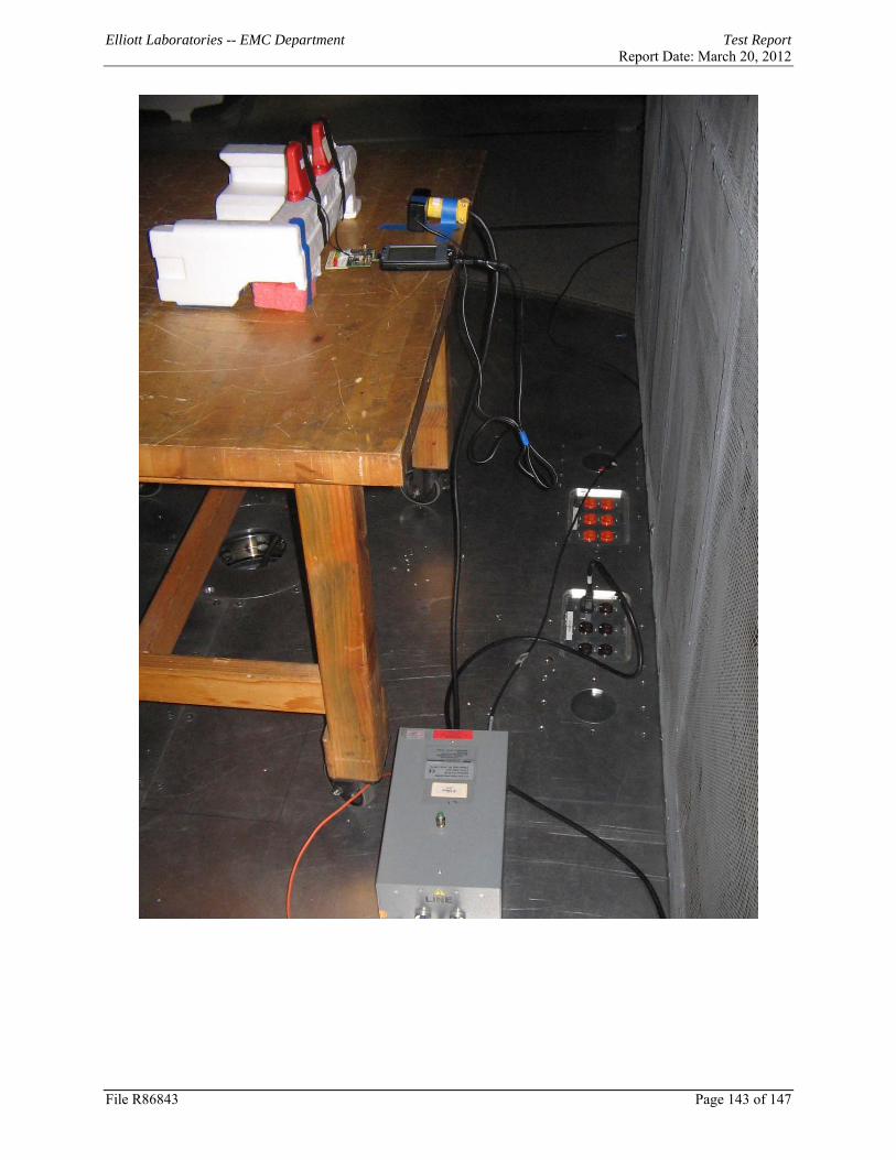
Elliott Laboratories -- EMC Department Test Report Report Date: March 20, 2012
File R86843 Page 143 of 147
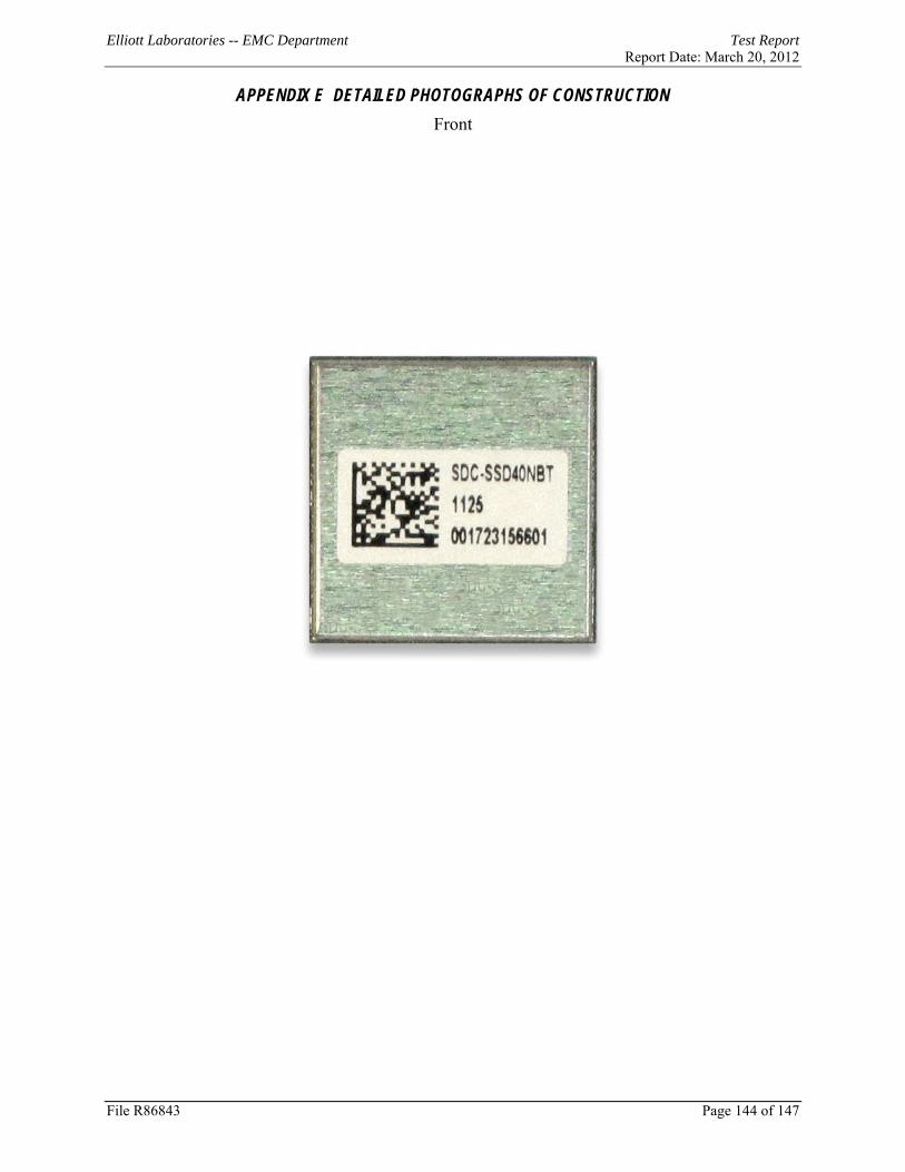
Elliott Laboratories -- EMC Department Test Report Report Date: March 20, 2012
APPENDIX E DETAILED PHOTOGRAPHS OF CONSTRUCTION Front
File R86843 Page 144 of 147
Elliott Laboratories -- EMC Department Test Report Report Date: March 20, 2012
Back
File R86843 Page 145 of 147

Elliott Laboratories -- EMC Department Test Report Report Date: March 20, 2012
Internal
File R86843 Page 146 of 147

Elliott Laboratories -- EMC Department Test Report Report Date: March 20, 2012
File R86843 Page 147 of 147
End Of Report This page is intentionally blank and is the last page of the report.