Embed Size (px)
Citation preview

7/20/2017 1 www.onsemi.com
Test Procedure for the RSL10-002GEVB Evaluation Board
INTRODUCTION RSL10 is a multi-protocol Bluetooth 5 certified System on Chip (SoC) which brings ultra-low-power wireless connectivity to
IoT and "connected" health and wellness devices.
Assembled RSL10 evaluation board (make note of the 9 jumper positions):
Figure 1: Assembled board.
SETUP The following list of equipment is required for testing, see Figure 2:
1. A computer with an internet connection and 4 USB ports.
2. An ammeter that can measure uA.
3. JLink JTAG box with an appropriate 10 pin SEGGER programmer connector.
4. 1 micro USB cable for the Device Under Test (DUT).
5. 1 DIO testing rig.
6. 1 RF enclosure containing a Lower Tester RSL10 board, 80dB fixed attenuators, two SMA adaptor cables,
and a USB cable. These additional cables should already be connected to the RF enclosure.

7/20/2017 2 www.onsemi.com
Figure 2: Required hardware for testing.
Inside the RF enclosure (see Figure 3) you can find:
1. Extra cables in the ESD bag.
2. The Lower Tester board. This board has been characterized by our team and the RF performance is very
well documented. The LEDs on the board will be on if the board is powered.
3. The conductive RF path.
4. The USB connection.
Figure 3: Contents of the RF box.
1
1
6
3
4
5
2
4
3 2

7/20/2017 3 www.onsemi.com
Insure the following applications are installed into your machine (the application installs can be found in the Installs folder).
Note, this installation process only needs to be done once.
1. Python 2.7
a. Navigate to ColoradoProductionTest\Installs\Python_Installs.
b. Run python-2.7.10.msi. Follow the normal installation instructions.
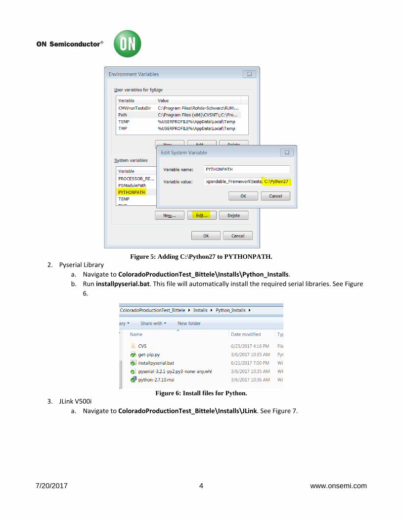
c. Make sure C:\Python27 is added to the computer’s PATH environment variable. See Figure 4.
d. Make sure C:\Python27 is added to the computer’s PYTHONPATH environment variable. See
Figure 5.
e. Restart the computer for these changes to take effect.
Figure 4: Adding C:\Python27 to the PATH.
7/20/2017 4 www.onsemi.com
Figure 5: Adding C:\Python27 to PYTHONPATH.
2. Pyserial Library
a. Navigate to ColoradoProductionTest_Bittele\Installs\Python_Installs.
b. Run installpyserial.bat. This file will automatically install the required serial libraries. See Figure
6.
Figure 6: Install files for Python.
3. JLink V500i
a. Navigate to ColoradoProductionTest_Bittele\Installs\JLink. See Figure 7.

7/20/2017 5 www.onsemi.com
Figure 7: Install file for the JLink application.
b. Run Setup_JLink_V500i.exe.
c. Follow normal install instructions, however, when prompted to select an installation directory,
make sure to install it to the ColoradoProductionTest_Bittele\Installs\JLink. Folder. See Figure
8.
Figure 8: Change the installation path to the JLink folder provided by us.
PROGRAMMING THE ATMEL To fully test the board, the Atmel IC on the bottom of the board needs to be programmed. This will allow us to communicate
to the board over USB.
1. Connect the Device Under Test (DUT) to the laptop with the micro USB cable. This will supply power to
the board. See Figure 9. Note that the board does not need to be in the testing jig for this process.
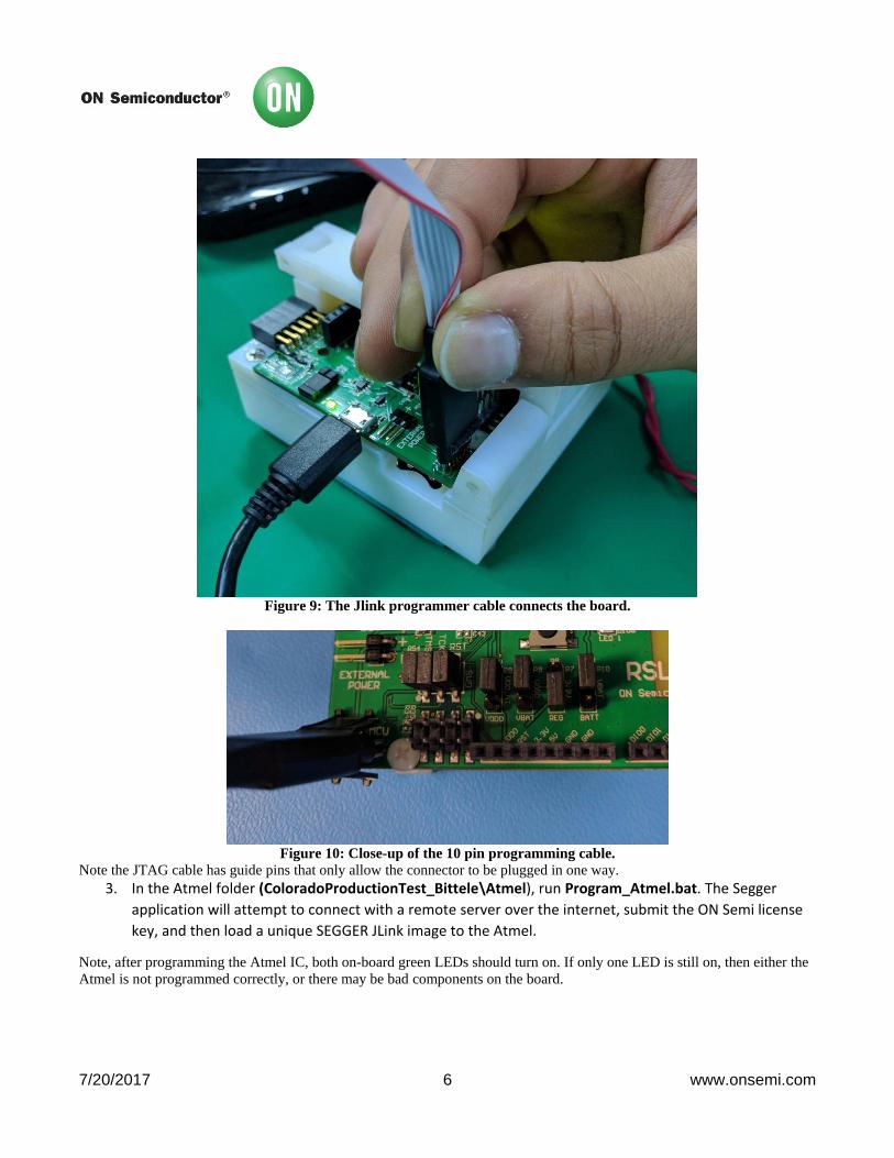
2. Connect the JTAG programmer cable to the board in the following configuration:
7/20/2017 6 www.onsemi.com
Figure 9: The Jlink programmer cable connects the board.
Figure 10: Close-up of the 10 pin programming cable.
Note the JTAG cable has guide pins that only allow the connector to be plugged in one way.
3. In the Atmel folder (ColoradoProductionTest_Bittele\Atmel), run Program_Atmel.bat. The Segger
application will attempt to connect with a remote server over the internet, submit the ON Semi license
key, and then load a unique SEGGER JLink image to the Atmel.
Note, after programming the Atmel IC, both on-board green LEDs should turn on. If only one LED is still on, then either the
Atmel is not programmed correctly, or there may be bad components on the board.
7/20/2017 7 www.onsemi.com
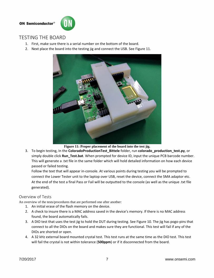
TESTING THE BOARD 1. First, make sure there is a serial number on the bottom of the board.
2. Next place the board into the testing jig and connect the USB. See Figure 11.
Figure 11: Proper placement of the board into the test jig.
3. To begin testing, In the ColoradoProductionTest_Bittele folder, run colorado_production_test.py, or
simply double click Run_Test.bat. When prompted for device ID, input the unique PCB barcode number.
This will generate a .txt file in the same folder which will hold detailed information on how each device
passed or failed testing.
Follow the text that will appear in-console. At various points during testing you will be prompted to
connect the Lower Tester unit to the laptop over USB, reset the device, connect the SMA adaptor etc.
At the end of the test a final Pass or Fail will be outputted to the console (as well as the unique .txt file
generated).
Overview of Tests An overview of the tests/procedures that are performed one after another:
1. An initial erase of the flash memory on the device.
2. A check to insure there is a MAC address saved in the device’s memory. If there is no MAC address
found, the board automatically fails.
3. A DIO test that uses the test jig to hold the DUT during testing. See Figure 10. The jig has pogo-pins that
connect to all the DIOs on the board and makes sure they are functional. This test will fail if any of the
DIOs are shorted or open.
4. A 32 kHz external board mounted crystal test. This test runs at the same time as the DIO test. This test
will fail the crystal is not within tolerance (500ppm) or if it disconnected from the board.

7/20/2017 8 www.onsemi.com
5. An RF test that runs a DTM script that requires the Lower Tester FR enclosure to be connected to the
laptop.
a. The application loaded onto RSL10 will first put the device in DC/DC power mode (testing the
inductor and capacitor placement).
b. An SMA adaptor cable (coming from the RF Lower Tester Box) is then connected to the DUT. See
Figure 12 Make sure you hear/feel a click sounds with connecting the cable. This will tell you
that a good connection has been made. Note that after a few hundred cycles, this cable may get
old and worn-out. When this happens, use one of the extra cables provided (see Figure 3).
c. The test will pass as long as we measure a packet error rate (PER) of less than 30%.
Figure 12: Connecting the RF SMA adaptor cable.
6. Loading the final “peripheral-server-sleep” application onto RSL10. The boards will be shipped with this
image loaded in flash memory.
7. A current measurement test that will require the use of an ammeter connected to the current measure
pins. A current draw of less than 500uA should be read. Ideally you want to use an ammeter that does
very little averaging. See Figure 13 and Figure 14:

7/20/2017 9 www.onsemi.com
Figure 13: This jumper is to be removed to make a current measurement. Connect ammeter in series.
Figure 14: Connecting the current measuring cable.
8. Once all other tests have passed without failure, a final PASS will be outputted to the terminal.
NOTE: whenever prompted to reset the device, press the on board reset button. See Figure 15.

7/20/2017 10 www.onsemi.com
Figure 15: Reset button location.
COMPLETION Upon completion of the production test, replace the current jumper back onto the current measure pins.
Revision History
Revision Comments Release Date By
0.1 Initial revision 2017-02-17 Suril Shah
0.2 Added details + images 2017-03-02 Suril Shah
0.3 Clarified + updated tests (as per MIS request) 2017-03-07 Suril Shah
0.4 Added details for the MAC address assignment procedure 2017-04-27 Suril Shah
1.0 Modified for use with mass production EVB 2017-06-22 Suril Shah
1.1 Updated content as per suggested by the Bittele team. 2017-06-27 Suril Shah