Embed Size (px)
Citation preview
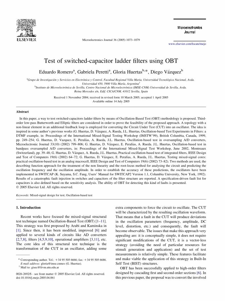
Test of switched-capacitor ladder filters using OBT
Eduardo Romeroa, Gabriela Perettia, Gloria Huertasb,*, Diego Vazquezb
aGrupo de Investigacion y Servicios en Electronica y Control, Facultad Regional Villa Maria, Universidad Tecnologica Nacional, Avda.
Universidad 450, 5900 Villa Marıa, Argentina1
bInstituto de Microelectronica de Sevilla, Centro Nacional de Microelectronica (IMSE-CNM) Universidad de Sevilla, Avda.
Reina Mercedes s/n, Edif. CICA/CNM, 41012 Sevilla, Spain
Received 1 November 2004; received in revised form 10 March 2005; accepted 1 April 2005
Available online 14 July 2005
Abstract
In this paper, a way to test switched-capacitors ladder filters by means of Oscillation-Based Test (OBT) methodology is proposed. Third-
order low-pass Butterworth and Elliptic filters are considered in order to prove the feasibility of the proposed approach. A topology with a
non-linear element in an additional feedback loop is employed for converting the Circuit Under Test (CUT) into an oscillator. The idea is
inspired in some author’s previous works (G. Huertas, D. Vazquez, A. Rueda, J.L. Huertas, Oscillation-based Test Experiments in Filters: a
DTMF example, in: Proceedings of the International Mixed-Signal Testing Workshop (IMSTW’99), British Columbia, Canada, 1999,
pp. 249–254; G. Huertas, D. Vazquez, E. Peralıas, A. Rueda, J.L. Huertas, Oscillation-based test in oversampling A/D converters,
Microelectronic Journal 33(10) (2002) 799–806; G. Huertas, D. Vazquez, E. Peralıas, A. Rueda. J.L. Huertas, Oscillation-based test in
bandpass oversampled A/D converters, in: Proceedings of the International Mixed-Signal Test Workshop, June 2002, Montreaux
(Switzerland), pp. 39–48; G. Huertas, D. Vazquez, A. Rueda, J.L. Huertas, Practical oscillation-based test of integrated filters, IEEE Design
and Test of Computers 19(6) (2002) 64–72; G. Huertas, D. Vazquez, E. Peralıas, A. Rueda, J.L. Huertas, Testing mixed-signal cores:
practical oscillation-based test in an analog macrocell, IEEE Design and Test of Computers 19(6) (2002) 73–82). Two methods are used, the
describing function approach for the treatment of the non linearity and the root-locus method for analysing the circuit and predicting the
oscillation frequency and the oscillation amplitude. In order to establish the accuracy of these predictions, the oscillators have been
implemented in SWITCAP (K. Suyama, S.C. Fang, Users’ Manual for SWITCAP2 Version 1.1, Columbia University, New York, 1992).
Results of a catastrophic fault injection in switches and capacitors of the filter structure are reported. A specification-driven fault list for
capacitors is also defined based on the sensitivity analysis. The ability of OBT for detecting this kind of faults is presented.
q 2005 Elsevier Ltd. All rights reserved.
Keywords: Mixed-signal design for test; Oscillation-based test
1. Introduction
Recent works have focused the mixed-signal structural
test technique named Oscillation-Based Test (OBT) [1–11].
This strategy was first proposed by Arabi and Kaminska in
[1]. Since then, it has been modified, improved [6] and
applied to several kinds of circuits like AD converters
[2,7,8], filters [4,5,9,10], operational amplifiers [3,11], etc.
The core idea of this structural test technique is the
transformation of the CUT in an oscillator, adding some
0026-2692/$ - see front matter q 2005 Elsevier Ltd. All rights reserved.
doi:10.1016/j.mejo.2005.04.061
* Corresponding author. Tel.: C34 95 505 6666; fax: C34 95 505 6686.
E-mail address: [email protected] (G. Huertas).1 Mail to: [email protected]
extra components to force the circuit to oscillate. The CUT
will be characterized by the resulting oscillation waveform.
That means that a fault in the CUT will produce deviations
in the oscillation parameters (frequency, amplitude, DC
level, distortion, etc.) and consequently, the fault will
become observable. The issues that make this approach very
appealing are: it is conceptually simple, it does not require
significant modifications of the CUT, it is a vector-less
strategy (avoiding the need of particular resources for
stimuli generation and application) and the set of test
measurements is relatively simple. These features facilitate
and make viable the application of this strategy in Built-In
Self Test (BIST) structures.
OBT has been successfully applied to high-order filters
designed by cascading first and second order sections [6]. In
this previous paper, the proposal was to convert the involved
Microelectronics Journal 36 (2005) 1073–1079
www.elsevier.com/locate/mejo

E. Romero et al. / Microelectronics Journal 36 (2005) 1073–10791074
filters in harmonic oscillators with amplitude controlled by
limitation. From the test viewpoint, the natural partition
of these filters (in first and second order sections) allows
a relatively straightforward implementation of Design-
for-Test schemes (DfT).
On the other hand, ladder filters are an alternative for
implementing high-order filters, offering low sensitivity to
component variations. However, their topologies are very
complicated including multiple-loop negative-feedback
networks emulating the relations that take place in the
passive prototypes. The natural partition in first- and
second-order sections of cascade filters is no longer valid
for the ladder filters. This fact complicates the implemen-
tation of the OBT and/or DfT schemes.
The goal is to explore the application of the proposed
OBT methodology [6] to switched-capacitors ladder filters.
This work has never been reported, despite the importance
of this kind of filters. In this approach, for the sake of
illustration, the filters are third- order low pass and they are
not partitioned to be tested. Third-order structures serve as
vehicles to show the OBT application in SC ladder filters.
The oscillating conditions are analyzed using the root-locus
method and validated through simulation. Despite the fact
that only third-order ladder filters are addressed, the
technique employed here to establish the oscillation
parameters is quite general, and able to be extended to
higher order filters without the cumbersome handling of
high-order transfer functions.
2. OBT approach
Let us consider herein the OBT scheme proposed in
previous papers [6]. As was explained in [6], it is necessary
to close a feedback loop around the CUT structure in order
to reconfigure the system in a robust oscillator. The idea is
to avoid the dependence of the oscillation parameters on the
saturation characteristics of the active elements. This can be
done by selecting a non-linear element for the feedback
loop, to guarantee self-maintaining oscillations [6]. This
non-linear element also allows a precise control of the
oscillation amplitude.
A conceptual diagram of the above mentioned OBT
scheme can be observed in Fig. 1(a). In this figure, G(z)
represents the z-domain transfer function of the involved
filter. On the other hand, in Fig. 1(b) is depicted the
(a) (b)
Fig. 1. (a) OBT scheme. (b) A simple non-linearity: a comparator.
characteristic of a simple non-linear block (a comparator)
that can be used to implement the feedback path. In normal
mode, the feedback is disconnected and the filter performs
its regular function. In test mode, the non-linear element is
connected to the filter to implement the oscillator. In this
way, only the input and output of the filter are manipulated
to perform the test allowing a low intrusion in the structure.
On the other hand, from the point of view of OBT
application, it is particularly important to accurately predict
the parameters of oscillation (frequency and amplitude) by
analytical equations and/or by means of simulations.
All these issues were exhaustively considered in the
previously-reported works [6–10]. However, a requirement
to successfully apply the theory developed in [6–10] was
that the filter could be split in second-order sections (or
biquads). In this case, a straightforward way to implement
and model the feedback loops, an analytical (yet feasible)
test solution and a high fault coverage could be obtained.
In this work, let us point out the problems related to the
ladder filters. This kind of filters exhibits more complex
structures and cannot be split in smaller sections. Due to this
problem, an alternative way to carry out the proposed OBT
scheme (Fig. 1) has to be devised to achieve a feasible test
result.
3. Circuit under test
As was referred, the CUTs are third-order low-pass
switched-capacitors ladder filters. In order to evaluate the
ability of OBT to test all-pole filters and structures with
transmission zeroes, Butterworth and Elliptic prototypes
have been designed. For the sake of illustration, let us use
the bilinear-type structures proposed in [12]. The main
specifications are reported in Table 1 and the schematic
valid for both filters is depicted in Fig. 2. It should be
mentioned that the same topology is able to synthesize both
all-pole and pole-transmission zeroes functions with the
proper sizing of the circuit components.
The transfer functions of the third-order low-pass
Butterworth and Elliptic filters are given by expressions
Eqs. (1) and (2), respectively.
GðzÞjButterworth Zkðz C1Þ3
z3 Cb2z2 Cb1z Cb0
(1)
Table 1
Filter specifications
Specification Butterworth Elliptic
Passband (Hz) 0–500 0–500
Passband attenuation (dB) 3 0.099
Stopband (kHz) 1.080–12.5 4.103–12.5
Stopband attenuation (dB) 20 62.5
Sampling frequency (kHz) 25 25

+
-
E1
+
-
E2
+
-
E3
C1
C2
C3
C4
C5
C6
C7
C8
C9
C10
C11
C12
C13
S1
S2
S3
S6 S7
S5S4
S8 S9
S10 S11
S12 S13
S14 S15
VIN
VOUT
Fig. 2. Schematic of bilinear filters.
E. Romero et al. / Microelectronics Journal 36 (2005) 1073–1079 1075
GðzÞjElliptic Zkðz C1Þðz2 Cc1z Cc0Þ
z3 Cb2z2 Cb1z Cb0
(2)
Imag
inar
y A
xis
–8–5
–4
–3
–2
–1
0
1
2
3
4
5
–6 –4 –2 0Real Axis
Root locus LP butter 3rd order
2 4
Fig. 3. Butterworth filter root locus.
4. OBT implementation
The output of the filter (the input to the non-linear
element in the test mode, Fig. 1(a)) is approximately
sinusoidal due to the low-pass characteristics of the filters.
This fact allows using the linear approximation stated in the
describing function method [13,14] for the mathematical
treatment of the non-linear element. As a result, the
equivalent transfer function of the non linear element in
Fig. 1 can be expressed as:
NðAÞ Z4Vref
pA(3)
where Vref is the voltage reference and A is the oscillation
amplitude.
It should be highlighted that for some switched-
capacitors circuits the implementation of this oscillator
could conduct to an unstable behaviour, problematic point
for testing purposes. This is true when there is a direct path
between the input and output of the CUT and, consequently,
the comparator that implements the non-linear feedback
cannot reach a stable estate. To overcome this problem, a
latched comparator is considered, adding an extra delay in
the system, as has been used by the authors in other
references such as [6–10]. Moreover, this situation
corresponds to a realistic case when an extra delay exists
into the feedback loops in complex systems.
The characteristic equation of the oscillatory system is
expressed in Eq. (4) as
1 KzK1NðAÞGðzÞ Z 0 (4)
In this equation, N(A) is the non-linear element
describing function, G(z) is the filter under test transfer
function and zK1 is the delay introduced by the latched
comparator.
To force the oscillations, at least a pair of complex poles
of the proposed closed-loop system (Fig. 1(a)) has to be
placed onto the unit circle, whereas the possible remaining
poles must be within the unit circle in order to guarantee the
system stability.
A way to determine the oscillation conditions (gain N(A),
frequency and amplitude) is to solve Eq. (4). As was
explained, it is feasible when second-order filters are
considered. In this case, only an oscillation solution is
obtained related to all the biquad coefficients. However, the
order of the involved equations (fourth-order for the present
cases) complicates the mathematical treatment and makes
this method difficult to extend to higher-order filters. Due to
this fact, the root-locus method is used here to estimate the
oscillation parameters. Additionally, this method allows
obtaining useful information in a numerical or graphical
way using broadly extended tools like Matlab. The
oscillation frequency and the oscillation amplitude are
easily derived using this tool.
The root-locus for the case of the Butterworth filter is
depicted in Fig. 3. That is, the evolution of the system roots
is drawn as the gain N(A) is varying. In this figure, it is
possible to determine that two branches starting from the
initial position of the complex poles cross the unity circle
making the system oscillatory. At the cross point, the gain
(and consequently the value of the describing function)

Imag
inar
y A
xis
–1
–1
–0.5
–0.5
0
0
0.5
0.5
Real Axis
Root locus LP butter 3rd order
1
1
1.5
Fig. 4. Detailed Butterworth filter root locus.
Imag
inar
y A
xis
0.85
–0.3
0.9
–0.2
0.95
–0.1
0
1
0.5
Real Axis
Root Locus
1.05
0.2
1.1
Fig. 6. Detailed Elliptic filter root locus.
E. Romero et al. / Microelectronics Journal 36 (2005) 1073–10791076
and frequency can be evaluated. For test purposes, we are
interested in gradually finding more than an oscillation
mode in order to cover potential faults in all the filter
elements. However, for the addressed case, it is impossible
to obtain more than an oscillatory mode without introducing
major changes in the CUT or moving the feedback
connection point.
A detailed view of the interest region is shown in Fig. 4.
It may be clear from this figure that only an oscillation
solution can be achieved where the gain is the so-called
critical gain (that is, the value of the describing-function
related to the oscillation amplitude). On the other hand, if
the gain is smaller than the critical value, two pairs of
complex poles are found within the unit circle, and then, the
system will be stable (non-oscillatory). However, if the gain
is higher than the critical value, at least a pair of poles will
be out of the unit circle and the closed-loop system will
become unstable (although controlled by the comparator
saturation levels).
Imag
inar
y A
xis
–2–2.5–3–2
–1.5
–1
–1
–0.5
–0.5
0
0
1
1
0.5
0.5
1.5
1.5
2
–1.5Real Axis
Root locus LP Elliptic 3rd order
Fig. 5. Elliptic filter root locus.
In short, only an oscillation mode in the closed-loop
system is possible. That means, only information from this
pair of complex poles (responsible for the oscillations) is
obtained, and the other pair of poles does not allow to
extract any test information.
On the other hand, the root-locus for the Elliptic case is
depicted in Fig. 5. Two pairs of crosses at the unity circle are
observed for two different gains. However, the oscillation is
established for the pair of crosses corresponding to the lower
gain (Fig. 6). Again, the test information is coming from
only a pair of complex poles.
With the aim of validating the results obtained from the
above mentioned procedure, the oscillators were
implemented in SWITCAP [15], a special purpose simulator
intended for switched capacitor circuits. A comparison
between theoretical predictions and simulation results is
shown in Table 2. It can be seen that the proposed method
predicts the oscillation parameters with enough precision
for the applications. These values will be taken as reference
values in the fault analysis carried out in the next sections.
5. Catastrophic fault simulation result
With the aim of establishing the ability of the proposed
OBT scheme for detecting catastrophic faults, a fault
Table 2
Oscillation parameters
Butterworth
(VrefZ2.5 V)
Elliptic
(VrefZ2 V)
Theoretical predictions
Frequency (Hz) 651.0 745.1
Amplitude (V) G1.31 G1.46
SWITCAP simulations
Frequency (Hz) 657.9 735.3
Amplitude (V) G1.30 G1.55

Table 4
Non-detected faults for the Elliptic filter
Fault Fosc relative
deviation (%)
Aosc relative
deviation (%)
S3 s-on 0.0 K2.9
S3 s-short 0.0 K2.8
C6 open 0.0 K3.9
C7 open 0.0 K3.2
C11 open 0.0 K3.0
10.010 cases versus 77 injected faults
E. Romero et al. / Microelectronics Journal 36 (2005) 1073–1079 1077
simulation process is carried out. In this preliminary study,
let us focus the attention on the switches and capacitors of
the filter structure. The involved faults are switch stuck at
on, switch stuck at open, shorts in switches and shorts and
opens in capacitors. For all cases, let us assume that the
faults are single and permanent. The fault injection and
simulation process is automatically performed using
SWITTEST [16]. It should be mentioned that the saturation
effects of the operational amplifiers are considered in this
work, adding a block that model this effect in SWITCAP.
Let us consider that a fault is detected if it produces a
deviation in the frequency or in the amplitude of at least 5%.
This criterion has been used by other authors [17]. A total of
77 faults have been injected, being 10 undetected for the
case of Butterworth filter. For the case of Elliptic filter, the
same number of faults has been injected and only five
remain undetectable. However, these data correspond to a
relatively good fault coverage, not less than a 87%.
Non-detected faults are listed in Tables 3 and 4 for the
Butterworth and the Elliptic filters, respectively. That means
that the pair of complex poles responsible for the
oscillations is insensitive to this set of faults in the filter
elements collected in Tables 3 and 4.
It should be pointed out that good fault coverage is
achieved only if both frequency and amplitude are
monitored. In this sense, these measurements are comp-
lementary. In addition, other measurements may be taken
into account to improve the fault coverage, like DC level,
distortion, etc.
But, as a positive result, it can be proven that most of
these undetected faults only affect the stopband. Fig. 7
displays in bold the fault-free Bode for the Butterworth
filter. The other graphs in the figure represent the Bode
diagrams for the non-detected injected faults. As can be
seen, only one of these graphs clearly disagrees out of the
stopband with the nominal transfer-function. This case
would be the only case which can be consider as a
problematic undetected fault.
On the other hand, in order to improve the fault coverage
a possible idea would be to close the feedback loop around
the secondary outputs. Then, another oscillation modes are
excited leading to other oscillation results. This means to
Table 3
Non-detected faults for the Butterworth filter
Fault Fosc relative
deviation (%)
Aosc relative
deviation (%)
S14 s-open 0.0 K3.68
S3 s-on 0.0 C0.02
S3 s-open 0.0 K2.01
S3 s-short 0.0 C0.11
C2 open 0.0 K2.5
C5 open 0.0 K0.52
C6 open 0.0 K0.16
C9 open K3.7 K4.2
C11 open 0.0 0.0
C13 open 0.0 0.0
test the filter in more than one test phase. This possibility
would be essential in higher-order filters where only an
oscillation mode may not be enough to test the entire filter
and all its elements.
By the way of example, let us study the feasibility of the
previous idea in the Butterworth filter. If the reported
catastrophic fault simulation (Table 3) is repeated but now
closing the feedback loop around the second integrator
output in Fig. 2, 4 out of 10 undetected faults in Table 3 can
be properly detected with this extra oscillation mode.
Moreover, one of these four faults corresponds to the more
problematic case highlighted in Fig. 7. Then, by using two
test phases (one for each oscillation mode) the fault
coverage can be increased (in fact, 100% of faults affecting
the passband should be detected).
6. Deviation faults in capacitors
Finally, let us estimate the ability of the OBT approach to
detect deviation-type faults in this kind of filters, also called
parametric faults. To do this, variations in the capacitor
values of the filter can be injected.
Usually, these deviations are arbitrarily proposed and not
related to the frequency-domain circuit specifications. As a
consequence, they may cause either a small or a high
difference from the circuit fault-free nominal response.
However, in this work, let us consider as a fault a deviation
in the capacitor values shifting the filter frequency response
0 5e+03 1e+04frequency (Hz)
–90.0
–40.0
volta
ge (
db)
Fault-Free Bode
Fig. 7. Non-detected faults in the Butterworth filter.

0Bode Diagram
–20
–40
–60
–80
–100
–120101 102 103
Frequency (Hz)
upper limit
lower limitnominal
Fig. 8. Frequency–response tolerance band (elliptic case).
E. Romero et al. / Microelectronics Journal 36 (2005) 1073–10791078
out of a pre-established limit. The idea is to define a
tolerance band around the nominal frequency response.
The concept is displayed in Fig. 8. In this case, for the
sake of illustration, a tolerance band of G10% is
considered. This tolerance is valid for the pass, transition
and attenuations bands. The test engineer may impose
different values for each band.
A specification-driven fault list (out of the required
tolerance band) is generated with sensitivity calculations
made in the frequency domain by SWITCAP [15].
Generally, the sensitivity of the circuit to a parameter
deviation can be expressed as:
SjGðuÞjai
Zai
jGðuÞj
v
vai
jGðuÞj (5)
where ai is the value of the parameter under consideration
and jG(u)j is the module of the filter transfer function.
Using this expression, it is obtained the variation in the
value of jG(u)j under changes in the ai parameter. It should
be mentioned that this is a first-order approximation and
presents good precision for small changes in the considered
parameter.
The tolerance band of the filter can be modelled by Eq. (6)
below, where T is the tolerance admissible by the application,
DCi is the variation introduced in the capacitor Ci and SjGðuÞjCi
is the sensitivity to variations in the capacitor Ci.
ð1KTÞjGðuÞj!jGðuÞjCDCi
Ci
jGðuÞjSjGðuÞjCi
!ð1CTÞjGðuÞj
(6)
From Eq. (6), it is possible to write:
KT
SjGðuÞjCi
!DCi
Ci
!T
SjGðuÞjCi
(7)
This expression shows the condition that has to be
fulfilled for maintaining the filter transfer characteristic
inside the tolerance band. It should be taken into account
that this condition is obtained for each simulated frequency
point. The minimum of the absolute values of these
deviations is assumed as a representative fault and
considered for fault simulations. Finally, the procedure is
repeated for every capacitor in the circuit.
With this method, a list composed of two deviations for
every capacitor (one positive and one negative) is obtained.
The faults in the list are then simulated in order to establish
the so-called parametric fault coverage.
A total of 26 deviation faults have been injected in the
Butterworth filter and only five faults remained undetected
which corresponds to a 80% fault coverage.
For the case of the Elliptic filter, 26 deviation faults have
been also injected and 10 are non-detected. A deeper study
revealed that a group of these undetected faults cause
deviations in the filter stop-band. For this reason the procedure
was repeated considering only the pass and transition bands.
As a result, a new deviation fault list was generated. It can be
concluded from the fault simulation results that only four
deviation faults remain undetected. Despite these promissory
results, it should be mentioned that the considerations made
for generating the new fault list could be done only if the
application allows relaxing the tolerance in the stop band.
7. Conclusion
The proposal in this work was to use a previous version
of the OBT approach [6] to test switched-capacitors ladders
filters. As was explained, this kind of filter structures
presents a main problem: they cannot be split in independent
second-order sections, which was an important premise to
successfully apply this OBT method in biquad-based filters.
In this context, it is complex to determine the oscillation
mode, a numerical (graphical) method is required and, in
principle, only an oscillation mode is possible (and,
therefore, some faults can remain hidden).
However, the simulation results allow us to assert that
the poles responsible for the oscillations seem to contain
a significant test information, remaining poles seem
‘secondary’ from the viewpoint of test and a good fault
coverage is obtained. Moreover, this coverage may be
improved in higher-order SC ladder filters by closing more
than a feedback loop using other filter outputs.
Acknowledgements
This work was supported in part by the Spanish
TEC2004-02949/MIC project.

E. Romero et al. / Microelectronics Journal 36 (2005) 1073–1079 1079
References
[1] K. Arabi, B. Kaminska. Oscillation-based test strategy (OBTS) for
analog and mixed-signal circuits, US Patent Application, 1995.
[2] K. Arabi, B. Kaminska. Efficient and accurate testing of analog-to digital
converters using oscillation-test method, in: Proceedingsof the European
Design and Test Conference (ED&TC‘97), 1997, pp. 348–352.
[3] K. Arabi, B. Kaminska. Design for testability of integrated operational
amplifiers using oscillation-test strategy, in: Proceedings of the
International Conference on Computer Design, VLSI In Computers
and Processors, Austin, 1996, pp. 40–45.
[4] K. Arabi, B. Kaminska, Oscillation-test methodology for low-cost
testing of active analog filters, IEEE Transactions on Instrumentation
and Measurement 48 (4) (1999) 798–806.
[5] K. Arabi, B. Kaminska, Oscillation-based test method for testing an at
least partially analog circuit, US Patent Application, 1999.
[6] G. Huertas, D. Vazquez, A. Rueda, J.L. Huertas. Oscillation-based
Test Experiments in Filters: a DTMF example, in: Proceedings of the
International Mixed-Signal Testing Workshop (IMSTW’99), British
Columbia, Canada, 1999, pp. 249–254.
[7] G. Huertas, D. Vazquez, E. Peralıas, A. Rueda, J.L. Huertas,
Oscillation-based test in oversampling A/D converters, Microelec-
tronics Journal 33 (10) (2002) 799–806.
[8] G. Huertas, D. Vazquez, E. Peralıas, A. Rueda. J.L. Huertas,
Oscillation-based test in bandpass oversampled A/D converters, in:
Proceedings of the International Mixed-Signal Test Workshop,
Montreaux (Switzerland), 2002, pp. 39–48.
[9] G. Huertas, D. Vazquez, A. Rueda, J.L. Huertas, Practical oscillation-
based test of integrated filters, IEEE Design and Test of Computers 19
(6) (2002) 64–72.
[10] G. Huertas, D. Vazquez, E. Peralıas, A. Rueda, J.L. Huertas,
Testing mixed-signal cores: practical oscillation-based test in an
analog macrocell, IEEE Design and Test of Computers 19 (6) (2002)
73–82.
[11] E. Romero, G. Peretti, C. Marques, Oscillation test strategy: a case
study, Third IEEE Latin American Test Workshop, LATW,
Montevideo, Uruguay, 2002 pp. 94–98.
[12] R. Gregorian, K. Martin, G. Temes, Switched-capacitor circuit design
MOS Switched-Capacitor Filters: Analysis and Design, IEEE Press,
USA, 1989.
[13] J. Gibson, Nonlinear Automatic Control, McGraw-Hill, Japan,
1963.
[14] P. Fleischer, A. Ganesan, K. Laker, A switched capacitor oscillator
with precision amplitude control and guaranteed start-up, IEEE
Journal of Solid-State Circuits SC-20 (2) (1985).
[15] K. Suyama, S.C. Fang, Users’ Manual for SWITCAP2 Version 1.1,
Columbia University, New York, 1992.
[16] S. Mir, A. Rueda, T. Olbrich, E. Peralias, J.L. Huertas, SWITTEST:
Automatic Switch-Level Fault Simulation and Test Evaluation of
Switched-Capacitors Systems, Proceedings of the 34th Design
Automation Conference, 1997, pp. 281–286.
[17] M. Wong, On the issues of oscillation test methodology, IEEE
Transactions on Instrumentation and Measurement 49 (2) (2000)
240–245.