Embed Size (px)
Citation preview

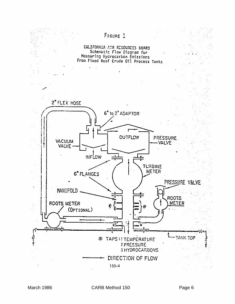
State of CaliforniaAir Resources Board
Method 150
Determination of Hydrocarbon EmissionsFrom Fixed-Roof Crude Oil Process Tanks
Adopted March 28, 1986

March 1986 CARB Method 150 Page 1
Method 150
Determination of Hydrocarbon EmissionsFrom Fixed-Roof Crude Oil Process Tanks
I. APPLICATION
The following test procedures are for determining the mass emissions ofhydrocarbon vapors emitted from fixed-roof crude oil process tanks up to 5,000-barrel capacity during normal processing conditions. Depending on processingconditions, larger tanks may require alternative methods that can handle largervolumes of vapor than provided by this method.
II. PRINCIPLE
During the normal operations at a fixed-roof crude oil process tank, all possiblepoints of emission are checked for vapor leaks. The product throughput isrecorded. The volume, concentration, temperature, and pressure of thehydrocarbon vapors emitted through a preselected vent on the process tank aremeasured. The mass emission of hydrocarbons is calculated from thesedeterminations.
III. TEST CONDITIONS
The process tank (or tanks) should be tested for 24 consecutive hours.However, a multi-day test period may be necessary to accommodate the varietyprocess variables and working conditions to which these tanks are exposed. TheAir Resources Board shall have the discretion of testing for longer or shorterperiods as may be necessary for properly evaluating the system. Usually asclose as possible, the system shall be tested under normal operating conditions,and shall be operated in accordance with established operating procedures.
IV. EQUIPMENT REQUIRED FOR CRUDE OIL PROCESS TANK TESTING
A. Volume meter (six-inch turbine meter) with a capacity to measure 30,000cfh. (849 m3/hr).
B. One (1) flow meter (two-inch positive displacement types) with a capacityto measure 3,000 cfh. (84.9 m3/hr). Another similar flow meter may berequired to measure intake volume.

March 1986 CARB Method 150 Page 2
C. Manifold with thermocouple, pressure, and HC analyzer taps for attachingthe flowmeters to the vent of the process tank.
D. Pressure/check valve that attaches to the exhaust side of the turbinemeter.
E. Pressure relief valve on the exhaust side of the out-breathing positivedisplacement meter. Set to open just before any of the tank’s normalpressure relief valves.
F. Vacuum/check valve for attaching to the inlet side of the in-breathingpositive displacement meter.
G. Couplers for attaching volume meters to the manifold.
H. Flexible hose (two-inch) for connecting in-breathing positive displacementmeter to vacuum/check valve.
I. One hydrocarbon analyzer (either FID with long capillary or ARB approvedequivalent) with an internal operating temperature of at least 200° F (93°C) and a capability of measuring vapor concentrations of 100 percent aspropane. The instrument shall be capable of direct analysis of raw vaporsfrom various petroleum products.
J. Two (2) 100-foot sections of heated sample line with controller capable ofmaintaining the vapor temperature at 225°F (107°C) or higher.
K. One (1) flexible thermocouple or thermister (0-225°F (-17.7°C-107°C) witha recorder system.
L. One (1) pressure sensing device capable of measuring from minus fiveinches to plus five inches of water with recorder system.
M. Portable combustible gas detector.
N. Barometer.
O. Appropriate containers and devices for collecting grab samples of HCvapor.
P. Appropriate containers and devices for collecting samples of crudeproduct.

March 1986 CARB Method 150 Page 3
Q. Continuous recorders compatible with the output voltages of the analyzersand transducers (i.e., THC, pressure, temperature, etc.) and using stripchart paper with 100 divisions minimum.
V. TEST PROCEDURES
A. The test equipment configuration as shown in Figure 1 shall be designedto duplicate, as close as practical, the original pressure/vacuum conditionsof the tank. In general, when replacing existing equipment with testequipment, the test equipment shall not create a burden upon the tank inexcess of that originally imposed by the existing equipment.To avoid creating a potentially hazardous work environment, the test shallbe conducted in compliance with safety practices observed by thepetroleum industry and with the rules and regulations promulgated bygovernment agencies.
B. Inspect tank and associated equipment including pressure/vacuum forliquid and vapor leaks. A portable combustible gas detector may bevaluable for detecting fugitive vapor leaks. Any leaks detected should benoted and an estimate should be made of the quantity of the leak. Thisinformation should be recorded in the source test. If an estimate withinthe accuracy of the test cannot be made, then corrective action must betaken.
C. Connect the manifold to a vent of the tank (see Figure 1).
D. Connect the volume meters and check valve to the manifold (see Figure1).
E. Connect the pressure and vacuum relief valves as appropriate (see Figure1).
F. Connect one end of the heat trace line to the appropriate tap on themanifold. (Fire and safety regulations may prevent direct connection.)Connect the other end of the heat trace line to the hydrocarbon analyzerwith recorder.
G. Connect the thermocouple (with recorder) to the appropriate tap on themanifold.
H. Connect the pressure sensing device (with recorder) to appropriate tap onmanifold.
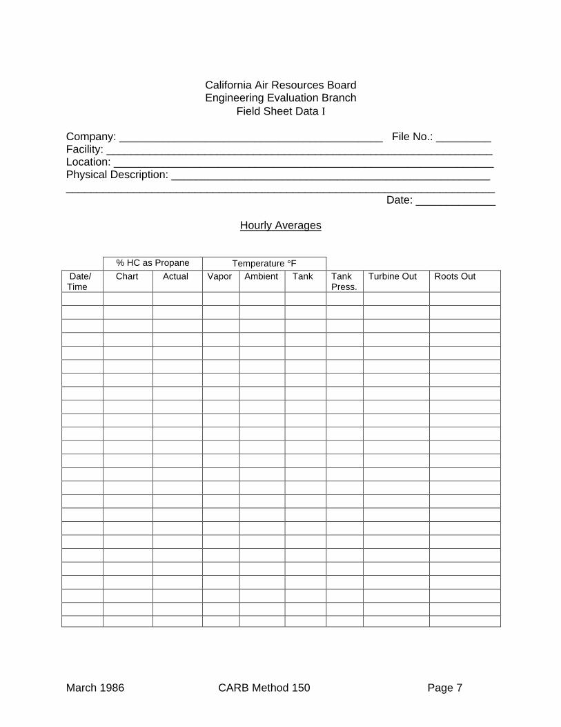
I. Manually record hourly readings of the volume meters, temperature,pressure indicators, and hydrocarbon analyzer during the test period on

March 1986 CARB Method 150 Page 4
“Field Data Sheet Ι” (attached). This is in addition to the informationcollected by continuous recorders.
J. Hourly record tank throughput, tank temperature, liquid level, barometricpressure, and other information that may be desirable on “Field DataSheet ΙΙ” (attached).
K. Collect at least three grab samples of the emitted vapors during the testinterval for laboratory analysis. (Analysis should include totalhydrocarbons, speciate C1-C9 and greater than C9, and other analyses asmay be desired).
L. Collect at least three samples of the crude product (see attached LiquidSampling Procedure for the recommended method) during the test intervalfor laboratory analysis. (Analysis of the crude oil layer should includespecific gravity (60/60°F), Reid or total vapor pressure, initial boiling point,flash point, and speciate C5-C20, less than C5 and greater than C20).
M. Optionally, complete the Fixed Roof Tank Evaluation Form (attached).
N. At the end of the specified time, disconnect all instrumentation, couplers,and the spool from the process tank.
VI. CALCULATIONS
A. Total volume of vapors discharged through the process tank vent.
Vs = Vm x 528 x (Pb + Pv /13.6)Tv x 29.92
Where:
Vs = Total volume of vapors corrected to 68°F and 29.92 in. Hg. (Ft3).
Vm = Measured volume of vapors (Ft3).Pb = Average barometric pressure (in. Hg.).Pv = Average pressure in process tank (in. H2o).Tv = Average vapor temperature (°R).
B. Weight of HC vapors vented
Wr = Cr x Vs x Mr
385Where:

March 1986 CARB Method 150 Page 5
Wr = Weight of hydrocarbons vented (lbs.).Cr = Average concentration (by volume) of hydrocarbons as a decimal
fraction.Vs = From (A.) above.Mr = Molecular weight of hydrocarbon used to calibrate hydrocarbon
analyzer (lbs./lb.mole).385 = Volume of 1 lb-mole of ideal gas at 68°F and 29.92 in. Hg. (ft3/lb-mole)
VII. CALIBRATIONS
A. Flow meters. Standard methods and equipment shall be used to calibrate theflow meters. The calibration curves are to be traceable to the National Bureau ofStandards (NBS) standards. Additionally, the flow measuring system is to becalibrated as a unit.
B. Temperature recording instruments. Calibrate prior to test period, daily duringthe test period and immediately following the test period using ice water (32°F)and a known temperature source of about 100°F.
C. Pressure recording instruments. Calibrate pressure transducers immediatelybefore, during, and immediately after test with a static pressure calibration for arange of –5 to +5 inches of H2O.
D. Total hydrocarbon analyzer. Follow the manufacturer’s instructions concerningwarm-up time and adjustments. Zero and span the analyzer prior to the test,daily during the test, and immediately following the test with zero gas containingnot more than 3 ppm HC and span gases of propane at approximately 30 and 70percent of full scale.
E. A record of all calibrations made is to be maintained.
March 1986 CARB Method 150 Page 6
March 1986 CARB Method 150 Page 7
California Air Resources BoardEngineering Evaluation Branch
Field Sheet Data Ι
Company: ___________________________________________ File No.: _________Facility: _______________________________________________________________Location: ______________________________________________________________Physical Description: __________________________________________________________________________________________________________________________
Date: _____________
Hourly Averages
% HC as Propane Temperature °F Date/Time
Chart Actual Vapor Ambient Tank TankPress.
Turbine Out Roots Out

March 1986 CARB Method 150 Page 8
California Air Resources BoardEngineering Evaluation Branch
Field Sheet Data ΙΙ
Company: ___________________________________________ File No.: _________Facility: _______________________________________________________________Location: ______________________________________________________________Physical Description: __________________________________________________________________________________________________________________________
Date: _____________
March 1986 CARB Method 150 Page 9
LIQUID SAMPLING PROCEDURE
INTRODUCTION
The sampling method described below has been developed for sampling from fixed-rooftanks and/or sample taps located upstream of the tank. It is the authors belief that thisprocedure, or one essentially equivalent, is necessary to obtain samples for vaporpressure measurements or light end composition (C-1 to C-6 hydrocarbons) analysis.The method is proposed for use in a study of hydrocarbon emissions from fixed-rooftanks in which emissions correlation with the stored liquid vapor pressure is verydesirable. However, the basic method should be applicable to many situations whichdemand collection of a sample without subsequent evaporation loss. All liquid samplesshould be obtained immediately prior to starting a test, during a test, or immediatelyafter completing a test, whichever is appropriate for the given test conditions. Samplestaken at any other time have to be considered as of no use as they cannot beconsidered to be representative of the tank’s contents during the test period.
SCOPE
This method is designed to avoid evaporation loss while obtaining, storing, andtransporting liquid samples.
A. PRECAUTIONS
Vapor pressure and the light end composition are extremely sensitive toevaporation losses. Therefore, when obtaining, storing, or handling samplesgreat care must be taken to ensure having representative samples. Sampleswhich are to be shipped must conform to all applicable federal, state, and localregulations. When samples are obtained from a sample tap by flowing theproduct through the sample container, all pertinent regulations and precautionsagainst fire, explosion, and other hazards must be observed.
B. SAMPLING EQUIPMENT
(For items 1-5 see Figure 1)
1. Stainless steel sample cylinders with a minimum volume of 300 cc andhaving valves (needle or ball with at least a ¼ inch opening) at each end.
2. Viton “O” ring equipped Circle Seal Check Valve (Cat. No. 249B-6PP) orequivalent.
3. Seven-foot lengths of 3/8 inch OD stainless steel tubing.

March 1986 CARB Method 150 Page 10
4. Fifty-foot length of 3/64 inch throttle cable with a 3/16 inch N.C. boltattached to one end.
5. ¾ inch pipe plug with 2 ½ inch long ¼ inch N.C. bolt screwed through it.
6. Appropriate scale with which to weigh the stainless steel cylinders.
7. Suitable connections to allow connecting the sample cylinder to a sampletap if one is available.
8. Wide mouth bottles.
9. Appropriate sampling apparatus to allow lowering a water-filled widemouth bottle into the tank and inverting it underneath the stock surface.
10. Appropriate range American Petroleum Institute (API) hydrometers.
C. PROCEDURE FOR TANK WITHOUT SAMPLE TAPS
(Refer to Figure 1 for the following instructions.)
1. Insert a clean, dry pipe plug (E) into a clean, dry relief valve (D) and adjust thebolt in the plug to fit firmly against the relief valve. (See NOTE 1.)

March 1986 CARB Method 150 Page 11

March 1986 CARB Method 150 Page 12
2. Attach this clean, dry relief valve assembly to a clean, dry, preweighedsample cylinder. Open needle valves (B) and (F) and evacuate the entireassembly by suitable means to 1mm Hg or less, absolute. Close theneedle valves. It is essential to have a high vacuum in the samplingsystem when a sample is being taken to ensure filling the cylinder liquidfull. If the cylinder and check valve assembly have no minor leaks thenthe system can be evacuated in a laboratory and the vacuum will bemaintained for several days. Alternately, one could have a good vacuumpump and a tilting McCloud gauge (to check the vacuum obtained) and dothe evacuation in the field immediately prior to sampling.
3. When ready to obtain a sample remove the pipe plug (E), attach thethrottle cable bolt to the relief valve, and attach a clean, dry 3/8 inch O.D.stainless steel tubing to the relief valve assembly. Open valve (F) andsubmerge the evacuated cylinder 3 to 5 feet (See NOTE 2) below thesurface of the liquid then pull the throttle cable to open the relief valve andallow liquid to enter the cylinder. Allow the relief valve to close beforeremoving the filled chamber from the tank. Clean the liquid from thesampling system as it is removed from the tank. Close valve (F) anddetach the relief valve assembly. Weigh the sample cylinder and from theliquid weight and the liquid gravity (as supplied by the tank operator ormeasured on site (See NOTE 2)) calculate the volume of the liquid in thecylinder. If the cylinder is less than 95% full then another sample is to betaken.
4. Hold the sample cylinder in a vertical position and open the bottom valveto drain off a small amount of product so that the cylinder meets theDepartment of Transportation regulations for shipment. DO NOT OPENTOP VALVE OR ALLOW AIR TO ENTER THE SAMPLE CYLINDER.
D. PROCEDURE FOR TANKS WITH SAMPLE TAPS
1. If tank sample taps are available then select the tap that is the closest tobeing 3 to 5 feet below the liquid surface. (See NOTE 2.) Open this tapand allow liquid to flow through it to a suitable receptacle until the residualtap line liquid is completely flushed out.
2. Connect a clean, dry evacuated sample cylinder to the tap with suitableconnections. (See NOTE 1.) The cylinder MUST be connected to thesample tap in such a way that it can be filled from the bottom. In generalthis will probably require having some clean, dry pipe and elbowsavailable which can be used to enable connecting the tap to the bottomcylinder valve. This precaution ensures that any gas formed by flashingwhen the liquid enters the evacuated cylinder will subsequently becompletely flushed out of the cylinder. It is particularly important to

March 1986 CARB Method 150 Page 13
observe this precaution when sampling from a tap where the liquid beingsampled is under a positive pressure. Connect a hose to the top cylindervalve to run the excess liquid sample into a suitable receptacle. Thesample is then taken by: (a) first opening the tap, (b) second opening thecylinder valve nearest the tap, and (c) third opening the cylinder valvefurthest from the tap allowing liquid to flow through the cylinder to thesuitable receptacle.
3. When the five liquid volumes have passed through the cylinder isolate thesample by reversing the above operations, i.e. (a) first close the cylindervalve furthest from the tap, (b) second close the valve closest to the tap,and (c) third close the tap valve and then disconnect the cylinder from thetap.
4. Hold the sample cylinder in a vertical position and open the bottom valveto drain off a small amount of product so that the cylinder meetsDepartment of Transportation regulations for shipment. DO NOT OPENTOP VALVE OR ALLOW AIR TO ENTER THE SAMPLE CYLINDER.
E. PROCEDURE FOR SYSTEMS REQUIRING UPSTREAM SAMPLING
1. If immediately prior to the test tank the liquid product goes through a unitwhere a pressure reduction occurs then a liquid sample may have to betaken upstream of this unit. Upstream sampling is required for thefollowing three circumstances: (a) the vapors formed in the unit flowdirectly into the test tank vapor space, (b) because of the reducedpressure entrained gas enters the test tank with the liquid product, or (c)because of the reduced pressure gas bubbles from the liquid as soon asthe liquid enters the test tank.
2. If none of the foregoing three circumstances occur the test tank can besampled by either of the two methods previously described (C or D).
3. If ANY of the circumstances described in E-1 above is true then the liquidsample MUST be taken from a sample tap UPSTREAM of the unit wherethe pressure reduction takes place. When a suitable tap has been locatedthe sample can be obtained by the techniques given in D above.
NOTE 1:
After each use the sampling apparatus should be thoroughly cleaned with1,1,1-trichloroethane, or other appropriate solvent, then with a lighthydrocarbon solvent. Following the final cleaning the apparatus should bethoroughly dried to remove all traces of the solvent.

March 1986 CARB Method 150 Page 14
The cleaning of the check valve assembly, tap connections, and any partof the apparatus through or over which liquid might pass in going into thesample cylinder is absolutely necessary.
NOTE 2:
Before a liquid sample is taken one should obtain from the tank operatoras much information as possible about the tank contents. Of crucialinterest is the gravity(ies) of the stock(s) in the tank. Particularly withcrude oils it is possible that crudes having more than 2 degrees APIgravity difference may be present in the same tank. If this occurs thelighter crude will float on the heavier crude and since evaporation takesplace from the surface the liquid sample should consist of only the lightercrude. If the tank operator does not have the appropriate information thenliquid samples should be obtained at the following depths below the liquidsurface: 1 to 2 inches, 1 foot, 2 foot, 3 foot, and 5 foot. These samplescan be taken in wide mouth bottles by the water displacement method.The API gravity of each sample is then determined on site. If there is noappreciable gravity difference then a liquid sample can be taken in astainless steel cylinder between 3 to 5 feet below the liquid surface. Ifthere is more than 2 degrees API difference in the gravities then thesampling location should be chosen so that the lightest liquid is sampled.The sample can be taken by method D if a sample tap is available at thecorrect depth, otherwise the sample has to be taken by method C.

Page 1 of 6
March 1986 CARB Method 150 Page 15
Air Resources Board
FIXED ROOF TANK EVALUATION FORM
GENERAL INFORMATION Observer: __________________________________
Owner: _______________________________ Location: ______________________________________Operator: _____________________________ Tank No. ______________________________________Plant Personnel Contacted: _______________ Personnel Conducting Test: _______________________Dates of Observation: __________________________________________________________________Mode of Tank During Testing: Standing: ________________ Working: ___________________________
TANK PHYSICAL PARAMETERS
1. Year of Tank Construction:_____________________ Manufacturer: _______________________2. Color of Tank Walls: _______ _______ _______ _______ _______ _______ Black White Lt. Gray Dk. Gray Med. Gray Other __________________________ __________________________
Aluminum (Specular) Aluminum (Diffuse)
3. Color of Tank Roof: _______ _______ _______ _______ _______ ________ Black White Lt. Gray Dk. Gray Med. Gray Other
_______________________ ________________________ Aluminum (Specular) Aluminum (Diffuse)
4. Paint Condition: Poor:_______ Good: _________5. Insulation: Yes________ No: ________ Thickness: _________________ inches6. Coating of Inside of Tank Wall, If Any: ___________________________________7. Coating of Roof (Outside), If Any: _______________________________________8. Height: (Straight Wall) ________________________ Feet ____________ inches9. Diameter: __________________________________ Feet _____________inches10. Tank Type: Welded _________ Riveted _________ Bolted ____________11. Capacity of Tank: ______________ BBLS12. Roof Slope: _________________________________ ____________Inches/feet13. Internal Heaters: Yes____ No ____ If Yes: Steam _____ Hot Water ________14. Vapor Recovery System: Yes _____ No _____
If YES, Make-up of Gas Composition: Inert Gas ______ Hydrocarbons _______
15. Pressure/Vacuum Roof Vents:
Type _________ Number ________ Normal Settings ________ in H2O Vacuum ________ in H2O Pressure
Type _________ Number ________ Normal Settings ________ in H2O Vacuum
________ in H2O Pressure
16: General Comments That May Relate to H-C Emissions: _________________________________
_____________________________________________________________________________
_____________________________________________________________________________
_____________________________________________________________________________
_____________________________________________________________________________

Page 2 of 6
March 1986 CARB Method 150 Page 16
ALL TANK OPERATIONS
1. Name of Crude: ________________________________________________________________
2. Oil Field: ______________________________________________________________________
(If the Tested Tank Contained Distillate or Fuel Oil, Indicate Not Applicable on 1 or 2).
3. If Tank was Normally on Vapor Recovery, How long was Vapor Recovery Disconnected Prior to
the Test? ______________ hours
4. If There was an Internal Tank Heater, Was it Operating During the Test? Yes _____ No _____
5. Analyses That Were Performed on Liquid Samples Obtained Within One Week of the Test Dates
(e.g. API Gravity, REID Vapor Pressure, ASTM Distillation) _____________________________
_____________________________________________________________________________
_____________________________________________________________________________
STANDING TANK OPERATIONS
1. Describe the Operation of the Tested Tank During Testing. Include Information on Stock Depths
and How It Changes: __________________________________________________________
_____________________________________________________________________________
_____________________________________________________________________________
_____________________________________________________________________________
_____________________________________________________________________________
_____________________________________________________________________________
_____________________________________________________________________________
_____________________________________________________________________________
_____________________________________________________________________________
2. Describe the Immediate Upstream Operations Ahead of the Tested Tank. Include the Operating
Temperature and Pressure of the Upstream Unit. Examples of Upstream Operations Could be a
Heater Treater Unit, In-line Heater or a Storage Tank: __________________________________
_____________________________________________________________________________
_____________________________________________________________________________
_____________________________________________________________________________
_____________________________________________________________________________
_____________________________________________________________________________
Page 3 of 6
March 1986 CARB Method 150 Page 17
3. Provide a Simple Process Schematic of the Tested Tank and Process Operations Immediately
Upstream. An Example is Shown Below. The Schematic Should Show the System Used During
the Test. Show Location of Vapor Sampling Points and Where Liquid Sample was Obtained.
4. Indicate any Process Changes Made Specifically for the Emission Test which Would be Different
From Normal Operations ________________________________________________________
_____________________________________________________________________________
_____________________________________________________________________________
_____________________________________________________________________________
_____________________________________________________________________________
_____________________________________________________________________________
_____________________________________________________________________________
_____________________________________________________________________________
_____________________________________________________________________________

Page 4 of 6
March 1986 CARB Method 150 Page 18
EMISSION TEST DATA
1. Was a Tank Leak Check Performed? Yes ____ No _____
Results ______________________________________________________________________
_____________________________________________________________________________
2. Emergency Relief Valve Setting and Number During Observation: ________________________
_____________________________________________________________________________
Maximum Pressure of Tank During Observation:_______________________________________
Pressure Setting of Test Valves During Observation: ______________________
3. Describe Potential Safety Hazards: _________________________________________________
_____________________________________________________________________________
_____________________________________________________________________________
Were These Reported to Plant Personnel? Yes ______ No ______
Who was it Reported To: _________________________________________________________
_____________________________________________________________________________
4. Hydrocarbon Analyzer Used During the Observation (Name and Model Number): ____________
_____________________________________________________________________________
_____________________________________________________________________________
Description of Calibration Procedure (Time, Span, Gas and Concentration, Zero Drift, etc.). _____
_____________________________________________________________________________
_____________________________________________________________________________
_____________________________________________________________________________
5. Describe Vapor Grab Samples Collection During Observation. ___________________________
_____________________________________________________________________________
_____________________________________________________________________________
_____________________________________________________________________________
6. Was an OVA Analyzer Used by the Observer to Check the Hydrocarbon Concentration.
Yes _____ No ______ Results and Comparison with Test Results. ________________
_____________________________________________________________________________
_____________________________________________________________________________
_____________________________________________________________________________
_____________________________________________________________________________
_____________________________________________________________________________

Page 5 of 6
March 1986 CARB Method 150 Page 19
7. Comments Relating to Measuring Hydrocarbon Concentration (Leaks, Condensation, Erratic
Response, etc.) _______________________________________________________________
_____________________________________________________________________________
_____________________________________________________________________________
_____________________________________________________________________________
8. Describe Liquid Level Changes, Liquid Flow Rates and Through-Put Information During
Observation. __________________________________________________________________
_____________________________________________________________________________
_____________________________________________________________________________
_____________________________________________________________________________
_____________________________________________________________________________
9. Describe Vapor Flow Rates and Test Metering. _______________________________________
_____________________________________________________________________________
_____________________________________________________________________________
_____________________________________________________________________________
_____________________________________________________________________________
10. Describe the Location and Manner in Which Liquid Sample was Obtained. __________________
_____________________________________________________________________________
_____________________________________________________________________________
_____________________________________________________________________________
11. If Tank was Previously Tested by Engineering-Science or Others, List the Previous Test Results.
Previous Test Results:
Stock Parameters: Previous Test Current Test (if available)
Temp (°F) ___________ ___________
RVP (lbs.) ___________ ___________
Gravity (°API) ___________ ___________
BBLS/Day (in)___________ ___________
BBLS/day (out) ___________ ___________
Vapor Discharge (SCF/day) ___________ ___________
Avg. Molecular Wt. (LB/LB-Mole) __________ ___________
Methane Concentration (lb/1000SCF) __________ ___________
THC Concentration (lb/1000 SCF) __________ ___________
Methane Emissions (lbs/day) ___________ ___________
THC Emissions (lbs/day) ___________ ___________

Page 6 of 6
March 1986 CARB Method 150 Page 20
Remarks: _____________________________________________________________________
_____________________________________________________________________________
_____________________________________________________________________________
_____________________________________________________________________________
_____________________________________________________________________________
_____________________________________________________________________________
_____________________________________________________________________________
_____________________________________________________________________________
_____________________________________________________________________________
_____________________________________________________________________________
_____________________________________________________________________________
_____________________________________________________________________________
_____________________________________________________________________________
_____________________________________________________________________________
_____________________________________________________________________________
Signed _______________
______________________
______________________
______________________