Embed Size (px)
Citation preview
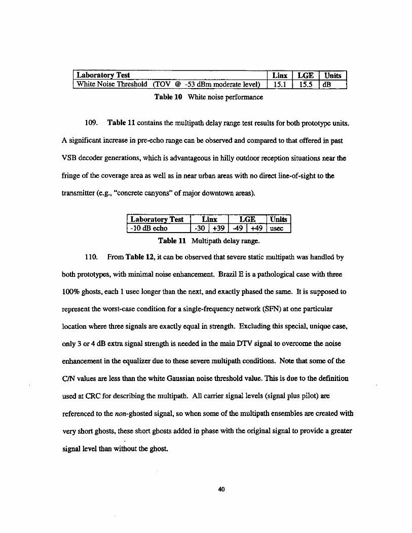
Laboratory Test White Noise Threshold (TOV @ -53 dBm moderate level) 15.1 1 15.5 I dB
I Linx I LGE I Units
Table 10 White noise performance
109. Table 11 contains the multipath delay range test results for both prototype units.
A significant increase in preecho range can he observed and compared to that offered in past
VSB decoder generations, which is advantageous in hilly outdoor reception situations near the
fringe of the coverage area as well as in near urban areas with no direa line-of-sight to the.
transmitter (e.& ‘‘concrete canyons” of major downtown areas).
Laboratory Test 1 Linx I LGE 1 Units -10 dB echo
Table 11 Multipath delay range. I -30 I +39 I -49 I 4 9 1 usec
110. From Table 12, it can he observed that severe static multipath was handled by
both prototypes, with minimal noise enhancement. Brazil E is a pathological case with three
100% ghosts, each 1 usec longer than the next, and exactly phased the same. It is supposed to
represent the worst-case condition for a single-frequency network (SFN) at one particular
location where three signals are exactly equal in strength. Excluding this special, unique case,
only 3 or 4 dJ3 extra signal strength is needed in the main DTV signal to overcome the noise
enhancement in the equalizer due to these severe multipath conditions. Note that some. of the
C/N values are less than the white Gaussian noise threshold value. This is due to the definition
used at CRC for describing the multipath. All carrier signal levels (signal plus pilot) are
referenced to the non-ghosted signal, so when some of the multipath ensembles are created with
very short ghosts, these short ghosts added in phase with the original signal to provide a greater
signal level than without the ghost.
40
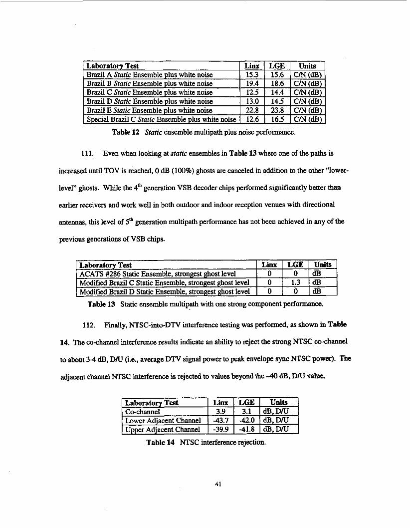
Table 12 Static ensemble multipath plus noise performance.
Laboratory Test
Modified Brazil C Static Ensemble, strongest ghost level ACATS #286 Static Ensemble, strongest ghost level
Modified Brazil D Static Ensemble, strongest ghost level
11 1. Even when looking at static ensembles in Table 13 where one of the paths is
increased until TOV is reached, 0 dB (100%) ghosts are canceled in addition to the other “lower-
level” ghosts. While the 4& generation VSB decoder chips performed significantly better than
earlier receivers and work well in both outdoor and indoor reception venues with directional
antennas, this level of 5& generation multipath performance has not been achieved in any of the
previous generations of VSB chips.
Linx LGE Units 0 O d B 0 1.3 dB 0 O d B
112. Finally, NTSC-into-DTV interference testing was performed, as shown in Table
14. The co-channel interference results indicate an ability to reject the strong NTSC co-channel
to about 3 4 dB, D N (Le., average DTV signal power to peak envelope sync NTSC power). The
adjacent channel NTSC interference is rejected to values beyond the -40 dB, DN value.
Table 14 NTSC interference rejection.
41
113. Note that the above tests at the CRC labs are 2-3 years old and made on early
prototype receivers (designed with FPGA chips). Both chip manufacturers have since received
their initial integrated chips and have stated that improvements over the prototype hardware have
been achieved. Both companies also state that fifth generation VSB consumer products will be
available on the market this year (2005). well before the April 2006 date on which the first
testing of digital signals of a limited number of stations can begin under SHVERA.
114. Even critics of the 8-VSB system have been impressed with the 5G-receiver
performance in severe multipath sites. After testing the 5G prototype in Baltimore at the same
sites at which previous VSB decoders failed, Sinclair Broadcasting put out a press release on
June 8,2004 (Ref 19). ‘We are pleased to see the progress made by Zenith that will allow
consumers to easily receive free digital television broadcasts in their homes. Broadcasters and
consumers can now look forward to robust DTV service delivered over-the-air without having to
subscribe to cable or satellite,” said Nat Ostroff, Vice President, New Technology, Sinclair
Broadcast Group. He went on to say: “[Tlhe innovations in the fifth-generation integrated
circuit allow it to lock onto signals in severe multipath environments even when the ghosts have
long delays or are larger than the main signal.”
115. In a similar report, engineer, consultant, and author Mark Schubin in his “Monday
Memo” on Thursday July 22,2004 (Ref a), was apparently not able to wait until the following
Monday to publish what he had learned. He stated: “Count me among the believers in the ffi-
generation LGkni th ATSC receiver! We just did a test this morning in my apartment, and I
thought the news was too important not to release immediately. With a simple loop antenna,
with no care in the positioning, we were able to pull in seven DTT stations reliably. When I say
‘reliably’, I mean not only that the pictures and sound were okay but that people could move
42
around the room and I could move the antenna around without causing any breakup. For the f i t
time, I could receive signals (six channels) from an antenna atop my TV, where I normally get
analog channels. I now believe that any “shmo” with reception conditions similar to mine can
simply take the receiver out of the box, connect a cheap loop antenna, stick it wherever it looks
good, and start to receive ATSC signals from all full-power, full-pattern stations.”
Conclusion
116. As consumers transition from analog television to digital television, they will
need to acquire a digital television receiver. For consumers who wish to receive local TV
stations over the air, a modest investment in a good quality rooftop receiving antenna (and
preamplifier, in appropriate cases), just as in the analog case, is a reasonable expectation.
117. The performance of digital television receivers continues to improve with each
new generation of products that are introduced into the market. The reception capabilities of
DTV receivers are continually improving and the performance of early-generation receivers, as
evidenced by the field test results, was sufficient to achieve a 90% System Performance Index.
It is reasonable to base the service eligibility criteria on the field strength of the received DTV
signal, rather than attempting to conduct subjective quality judgments at thousands of homes.
We can expect that this Service Performance Index will continue to increase as new products are
intWiUced.
118. The measurement procedures contained in Section 73.686(d) can be modified
easily to reflect proper measurement methodology for DTV signals. The change in measurement
instrumentation is the most significant, and there is readily available equipment in the market
that is capable of measuring the DTV signal power within the integrated 6MHz channel. Also,
these. measurements should be performed using an antenna with some gain and directionality in
43
order to minimize the effects of mnkipath and other impairments that may lead to inaccurate
power measurements.
Respectfully Submitted:
Id William Meintel
- Gary Sgrignoli
/ d Dennis Wallace
44
REFERENCES
1 ATSC Digital Television Standard, Document N53B (with amendments 1 and 2). www.atsc.org.
2 Fourth Report and Order, MM Docket 87-268, FCC 96-493, Federal Communications Commission, December 24, 1996.
3 Fifth Report and Order, MM Docket 87-268, FCC 97-116, Federal Communications Commission, April 3,1997.
4 Sixth Report and Order, MM Docket 87-268, FCC 97-115, Federal Communications Commission, April 3, 1997.
5 Memorandum Opinion and Order on Reconsideration of the Sixth Report and Order, MM Docket No. 87-268, FCC 98-24, Federal Communications Commission, February 17,1998.
6 “OET Bulletin No. 69: Longley-Rice Methodology for Evaluating TV Coverage and Interference”, FCC Office of Engineering & Technology, original version July 2,1997, revised version February 6,2004.
7 Code of Federal Regulations, Title 47, Telecommunications, Parts 70-79, Revised as of October 1,2M)3.
8 “Digital Television Standard for HDTV Transmission: ATSC Standard”, Doc. A53, Advanced Television Systems Committee, September 16,1995.
9 “Guide to the Use of the Digital Television Standard for HDTV Transmission”, Doc. AM, Advanced Television Systems Committee, October 4, 1995.
10 “VSB Tutorial”, Richard Citta and Gary Sgrignoli, Montreux Symposium, June 12,1997.
1 I Report 82-100, “A Guide to the Use of the ITS Irregular Terrain Model in the Area Prediction Mode”, by G. A. Hufford, AIG. Longley, and W.A. Kissick, US Department of Commerce, April 1982.
W. C o d , Dielectric Communications, NAB Engineering Conference, April 2005.
13 “Digital Grand Alliance: Record of Test Results”, submitted to Advisory Committee on
12 “Measured Performance Parameters for Receive Antennas used in DTV Reception”, Kerry
Advanced Television Services by AlTC, CableLabs, ATEL, Task Forces on Digital Specific Tests (Audio & Field Ta t s Systems Subcommittee/Working Party 2, ACATS), MSTV, PBS, Hitachi, and IBM, October 1995.
14 “ATSC VSB Transmission System Notes”, by Gary Sgrignoli, handout notebook used in VSB Seminars, 6/2/05 (see www.MSWdtv.com).
45
15 “Performance of 5th Generation 8-VSB Receivers”, T. Laud, M. Aitken, W, Bretl, K. Kwak, IEEE Transactions on Consumer Electronics, Vol50, No. 4, November 2004.
16 “An4 ATSC Recommended Practice: Receiver Performance Guidelines”, Advanced Television Systems Committee, June 18,2004.
17 “Results of the Laboratory Evaluation of Linx ATSC Prototype Receiver with 8-VSB Modulation for Terrestrial Broadcasting”, Final Report, Version 1.4, Communication Research Centre Canada, April 4,2002 (see CRC website: www.crc.ca)
18 “Results of the Laboratory Evaluation of ZenithSth Generation VSB Television Receiver for Terrestrial Broadcasting”, Report, Version 1.1, Communication Research Centre Canada, September 2003 (see CRC website: www.crc.ca )
19 Sinclair Broadcast Group press release, June 8,2004 (see Sinclair website: http://www .sbgi.net/press/release_200468/2.shtml).
20 “Monday Memo”, Mark Schubin, July 22,2004 (Schubin website: http://www.digitaltelevision.com/mondayrnemo/ndist/).
46

FIGURES
Antenna Dipole Gain 4 Factor Ga Kd
E - Cable
_3 Loss + L SNR, NF1
E (dBuV/m) = (kTB + NFl)+SNR + L + Kd - Ga
40.8 (dBuV/m) = -106 + 7 + 15 + 4 + 130.8 - 10
Figure 1 Block diagram of typical FCC receive site
Figure 2a Equalizer delay improvement with Figure 2b Equalizer amplitude improvement with generations generations
41
Ga
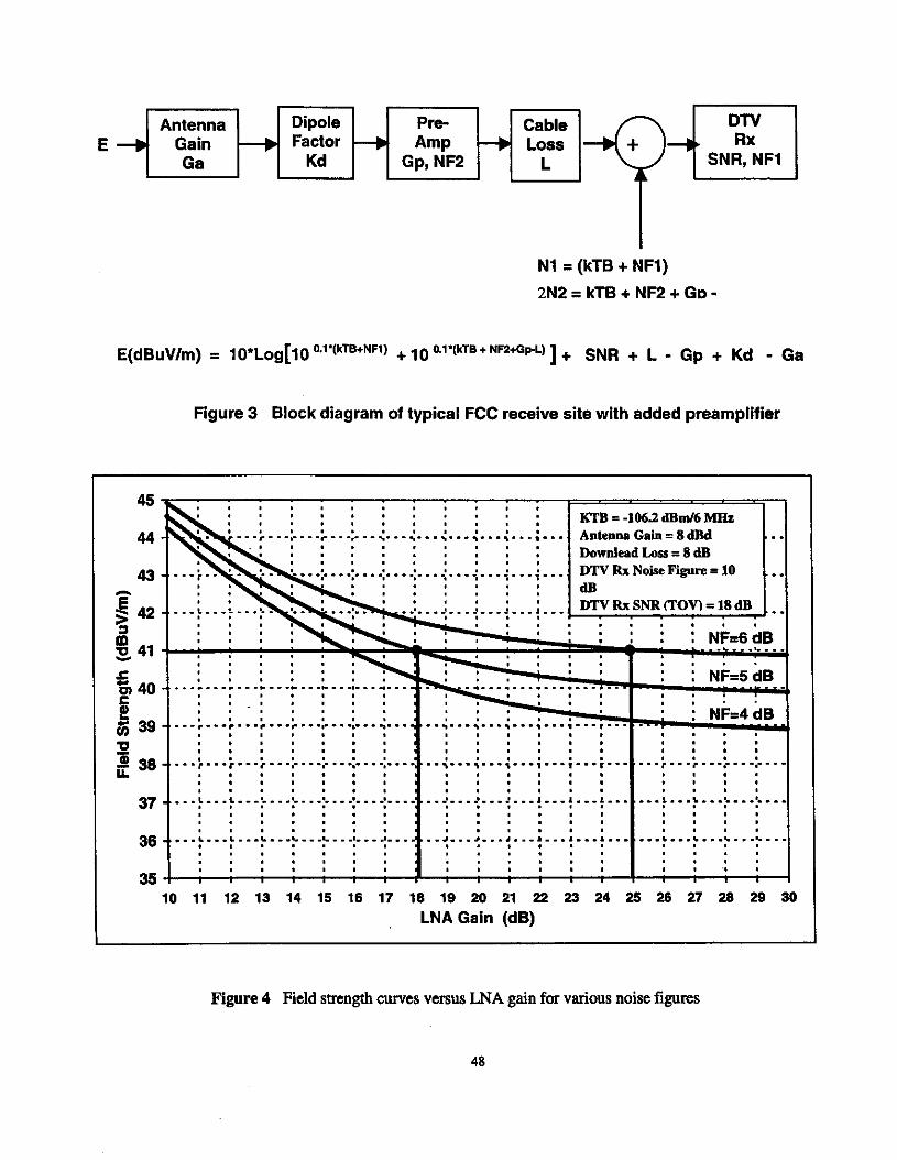
Figure 3 Block diagram of typical FCC receive site with added preamplifier
Kd Gp, NF2 L
. . . . . . . . . Downlead Loss = 8 dB
. . . . .
. I , . , . .
, , - , . I . I . . . . . . . . . . . . . . , 1 1 1 1 1 . . . . . . . I , , , . . . . . . . . . . . . . * , I , . . I , . . . . . . . . . . , . , . . . * I . . . . . . . . . , . , . . I . . ,
. . . . . . . . . 1 . 1 1 . . I . . . . . . . . . . . . . . , . I .
. . . . . . . . , . I . , 1 . 1 . 1 . 1 I , , , . , . . . . .
10 11 12 13 14 15 16 17 18 19 20 21 22 23 24 25 26 27 28 29 30 LNAGain (dB)
Figure 4 Field strength curves versus LNA gain for various noise figures
48

Exhibit A Qualifications of the Firm
Meintel. Serienoli. & Wallace
William Meintel
Mr. Meintel holds a degree in Electrical Engineering and has 36 years experience in the communications field. After graduation, he was employed by the Federal Communications Commission, first as a field engineer and then in the Mass Media Bureau's Policy and Rules Division. While in Policy and Rules, he served as the division's computer expert and directed the development of several major computer modeling projects related to spectrum utilization and planning.
He entered private practice in 1989, and has been heavily involved in technical consulting, computer modeling and spectrum planning for the broadcast industry. In April 2005, Mr. Meintel merged his consulting practice into the firm Meintel, Sgrignoli, & Wallace.
Mr. Meintel co-authored a report for the NAB on spectrum requirements for Digital Audio Broadcasting (DAB), created a plan for independent television broadcasting for Romania and has been extensively involved in spectrum planning for digital television (DTV) in both the US and internationally.
Mr. Meintel wrote the coverage and interference analysis software utilized to develop the DTV Table Of Allotments and is well versed in the application of Longley-Rice and other propagation models. Mr. Meintel also wrote the software for the FCC's processing of DTV applications utilizing OET-69. He is a member of IEEE and Tau Beta Pi.
Garv Serienolk
Gary Sgrignoli is a principal engineer and founder of Meintel, Sgrignoli, & Wallace. Mr. Sgrignoli received his MSEE from the University of Illinois in 1977. He was a Principal Engineer and Consulting Engineer at Zenith Electronics Corporation from 1977 till February 2004, when he left for private practice.
Mr. Sgrignoli has worked in the research, development, and design m a on television "ghost" canceling, cable TV scrambling, and cable TV two-way data systems before turning to digital television transmission systems. Since 1991, he has been extensively involved in the 8-VSB transmission system design, its prototype implementation, and lab and field tests with Zenith and the Grand Alliance.
-
He holds 35 U.S. patents, including some that are related to digital television transmission and the 8-VSB transmission system. Mr. Sgrignoli is a recipient of the JEEE Matti S. Suikloa award presented by the IEEE Broadcast Technology Society.
49

He was involved with the DTV Station Project in Washington DC, helping to develop DTV FW test plans. He has also been involved with numerous television broadcast stations around the country, training them for DTV field testing and data analysis, and participated in numerous DTV over-the-air demonstrations with the Grand Alliance and the ATSC, both in the U.S. and abroad. In addition to publishing technical papers and giving presentations at various conferences, he has given many of his VSB transmission system tutorials around the country. He is a member of Em.
Dennis Wallace:
Dennis Wallace has an extensive background in Digital Television Systems. Mr. Wallace managed all the Laboratory RF Testing of the Grand AlIiance ATSC HDTV System, having served as the RF Systems Engineer at the Advanced Television Test Center (AlTC). He managed test plans, configurations, and operations for Grand Alliance Testing and several Datacasting Systems. Prior to joining A'ITC, he held positions in Field Operations Engineering, Applications Engineering, and was Product Manager for two Television transmitter manufacturers.
In July 1997, Dennis founded Wallace & Associates a broadcast engineering and consulting f m specializing in Digital Television, RF Propagation Measuxements, Spectrum Policy issues, and Technical Consulting. His clients include major broadcast groups, The DTV Station Project, ATTC, Trade Associations, and both Professional and Consumer Electronics Manufacturers. In April of 2005 Wallace & Associates was merged into the f m of Meintel, Sgrignoli, &Wallace.
He has worked on the Broadcast side of the fence, as well, holding Chief Engineer and Operations Manager, positions with both Radio and Television Stations.
In 1999, Mr. Wallace was awarded the. prestigious Matti S. Suikola award by the EEE Broadcast Technology Society.
Mr. Wallace is a Certified Broadcast Television Engineer by the Society of Broadcast Engineers. He is also a member of the IEEE Broadcast Technology Society, SMFTE, an Associate member of the Federal Communications Bar Association, and is active on several industry standards committees and the ATSC.
50
ATTACHMENT 2
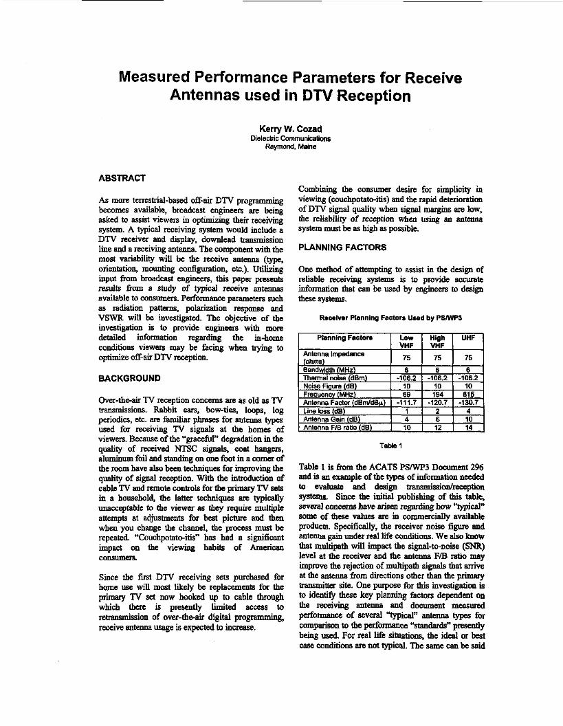
Measured Performance Parameters for Receive Antennas used in DTV Reception
Kerry W. Cozad Dielectric Communications
Ramond, Maine
ABSTRACT
As more terrestrial-based off-air DTV programming becomes available, broadcast engineers me being asked to assist viewers in optimizing their receiving system. A typical receiving system would include a DTV receiver and display. downlead transmission lime and a receiving antenns. The component with the most variability will be the receive antenna (type, orientation, mounting configuration, etc.). Utilizing input born broadcast enpineus, this paper presents results 6om a study of typical receive antennas available to consumers. Performance parameters such as radiation patterns. polarization response and VSWR will be invcstigatcd. The objective of the investigation is to provide engineer8 with more detailed information regardii the in-home conditions viewers may be facing when trying to optimize off-air DTV reception
BACKGROUND
Over-the-air TV reception concerns are as old as TV transmissions. Rabbit ears, bow-ties, loops, log periodic%, etc. are familiar phrases for antenna types used for receiving TV signals at the homes of viewers. Because of the “gracefur degradation in the quality of received NTSC signals, coat hangers, aluminum foil and sianding on one foot in a comer of the mom have also been techniques for improving the quality of signal reception. With the ktmducb ‘on of cable TV and remote controls for the primary TV sets in a household, the latter techn ip are typically unacceptable to the viewer as they require multiple attempts at adjustments for best picture and then when you change the channel, the process must be repeated. “Couchpotato-itis” has had a significant impact on the viewing habits of American
Since the iirst DTV receiving sets purchased for home use will mcst liiely be replacements for the primary TV set now hooked up to cable through which there is presently Limited access to retransmission of over-theair digital programming, receive antenna usage is expeaed to inuease.
consumela.
Combining the consumer desire for simplicity in viewing (couchpotatc-itis) and the rapid deterioratim of DTV signal quality when signal margins are low, the reliability of reception when using an antenoll system must be as bigb as possible.
PLANNING FACTORS
One methd of attemphg to assist in the design of reliable rewiving systems is to provide accurate information tbat can be used by engineen to design these systems.
Recelvrr Planning Factors Used by PSlWP3
I Planning Facton I Low 1 High I UHF 1 I VHF I VHF I I 75 I 75 1 76 Antenna ImpBdMm
Table 1
Table 1 is from the ACATS P S W 3 Docummt 2% and is an example of the types of information needed to evaluate and design transmissiodmxption systems. Since the initial publishing of this table, sevcral concerns bave Bljsen regarding how ‘typical” some of these values are io commercially available prcduck. Specifically, the receiver noise figure and antem gain under real life conditions. We also lmow that multipath will impact the signal-to-noise (SNR) level at the receiver and the antenun F/B ratio may improve the rejection of multipath signals that arrive at the antenna h m directions other than the primsty transmim site. One purpose for this investigation is to identify these key p l w factors dependent on the receiving antenna and document measured
comparison to the performance “standards” pnsentEy being used For real life situations, the ideal or best c ~ s e conditions are not typical. The same can be said
pcrfomce of s e v d “d” antenna types for
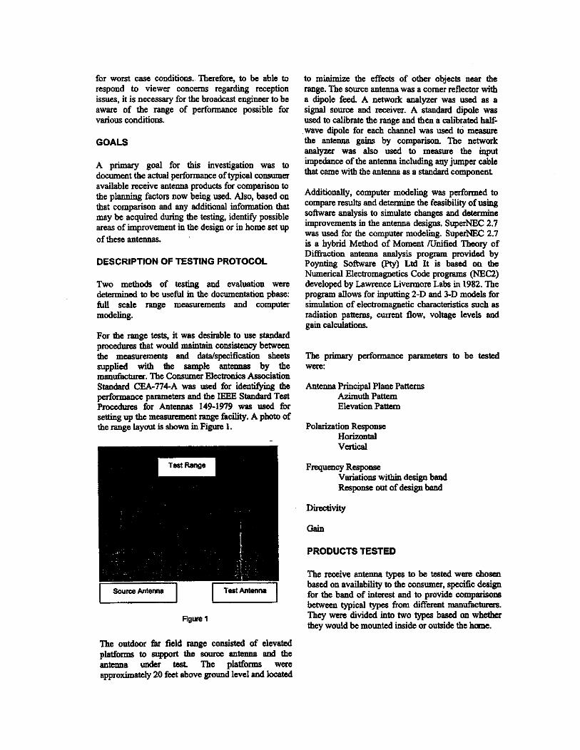
for worst case conditions. Therefore, to be able to respond to viewer concerns regardiig reception issues, it is necessary for the broadcast engineer to be aware of the range of performance possible for various conditions.
GOALS
A primary goal for this investigation was to document the actnal performance of typiosl consnmer available receive antenna products for comparison to the planning factors now being used. Also, based on that comparison and any a d d i t i d information that may be acquired during the testing, identify possible areas of improvement in the design or in home set up of these antennas.
DESCRIPTION OF TESTING PROTOCOL
Two methods of testing and evaluation were determined to be useful in the documentation pbase: full scale range measurements and computer modeling.
For the range tests, it was desirable to usc standard procedures that would maintain consistency b e t w m the measurements and daWspecification sheets supplied with tbc Mmple antcnw by the mauufbctum. Tbe Consumer Electronics Association Standard CEA-774-A was uscd for iden- the performance parameters and the IEEE Standard Test
setting up the mwmranmt range ik.ility. A photo of the range layout is shown in Figure 1.
hocedurcs for Anunnas 149-1979 w a ~ used for
F l g m 1
The outdoor far field range consisted of elevated
antenna under test The platfom were approximately 20 feet above ground level and located
platfom to support the 8ouIoe antema and the
to minimize the effect8 of other objects near the range. The SOurce antenna was a corner reflector with a dipole feed. A network analyzer was used as a signal source and receiver. A standard dipole was used to calibrate the range and then a calibrated half- wave dipole for each channel was w d to measm the antenna gains by comparison. The network analyzer was also used to measure the input impedance of the antenna including my jumper cable that came with the antenna as a standard component
Additionally, computer m o d e l i was performed to compare results and ' the feasibility of using sofhvare analysis to simulate changes and determine improvements in the antenna desigm. SuperNEC 2.7 was used for the computer modeling. Super= 2.7 is a hybrid Method of Moment /Unified Theory of Diffraction antenna analysis program provided by Poynting Software (€'ty) Ltd It is based on the Numerical Electromagnetics Code programs (NECZ) developed by Lawrence Livermore Labs in 1982. The program allows for inputting 2-D and 3-D models for simulation of electromagnetic characteristics such as radiation pattcms, cumnt flow, voltage levels and gain calculations.
The primary performance parameters to be tested were:
Antenna Principal Plane Patterns Azimuth Pattem Elevation Pattern
Polarization Response Horizontal Vertical
Frequency Response Variations within design band Response out of design band
Directivity
Gain
PRODUCTS TESTED
"he, receive antenna types to be tested were. chosen based on availability to the consumer, specific design for the band of interest and to provide cornparims between typical types from different manufacturw. They wm divided into two t&wa b a d 011 whether they would be mounted inside or outside the home.
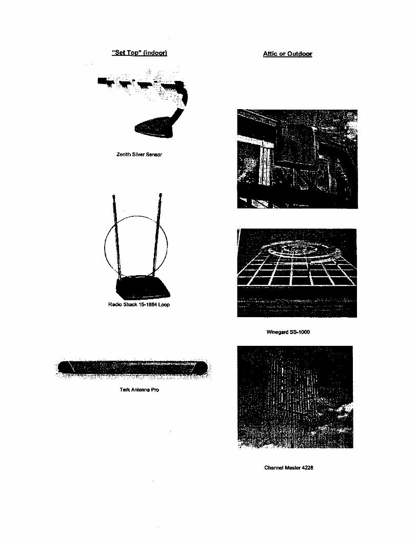
"Set TOP" lindood
Zeniih Silver Sensor
Radka Shack 161864 Lwp
... . . . . . . . . .
. . . . . . . ..... .......... ... .......................... ,., .......... :. ..: . :,:.v, ...:. . . . . . . . . . . . . . . . . . .
Tee Antenna Ro
Attic or Outdoor
Channel Master 4228
RCA ANT3020
Wlnegard PR-8800
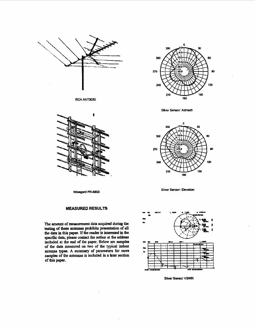
MEASURED RESULTS
The amount of measurement data acquired during the tcstiDg of thew antennas prohibits presentation of all
included at the end of the paper. Below are samples of the data measured on two of the typical indoor antenna t y p ~ A summary of paramctms for more samples of the antennas is included in a later d m of this pspcr.
the data in this pspcr. If the resdcr is interested in the specific data, please contact the author at the addrsgs
0
'180
Silver Sensor: Azimuth
Sliver S e m Uevation
Sliver Sensor VSWR
n
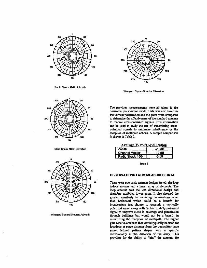
Radio Shack 1864: Azimuth Wlnegard SquareShooter: Elevation
180
Radio S b & 1864: Elevation
180
The previous measurements were all taken in the horizontal polarization mode. Data was also taken in the vertical polarization and the gains wen compared to determine the effectiveness of the standard antenna to receive cross-polarized signals. This information can be used to study the use of transmitting cram polarized signals to minimize interfnnra or the reception of multipatb echoes. A sample comparison is shown in Table 2.
Zenith -20 dB Channel Master -19 dB Radio Shack 1864
Table 2
OBSERVATIONS FROM MEASURED DATA
There were two hasic antenna designs tested: the loop indmr antenna and a hear array of elemmts. The loop antenna was the less directional design and therefore exhibited lower gains. It also showed the greater sensitivity to receiving polarizations other than horizontal which wuld be a benefit for broadcasters that choose to traasmit a vertically polarized signal along with the horizontally polarize3 signal to improve close in coverage and penetration through buildings but would not be a benefit in minimizing the reception of multipath Thc higher gain receive antennas that would typically be used for locations at m e distance finm the transmitter have more d e h d pattan shapes with a spcciiic directionality in the direotion of the array. This provides for thc ability to "aim" the antsma for
maximum signal and minimize reception of multipath reflections for other dmctions. Any benefit that might be provided by msmiaing a vertically polarized signal was not apparent
The one exception to the general antenna types described above was the Wmegard SquareSbooter. Its design is shown in the photo earlier and is a log periodic style design for broadband performance. It was thought that the vertically polarized signal response would be different for this design relative to the l i a m y antennas. It was more sensitive to vertical polarization but the levels were still more than -1OdB those for horizontal polarization.
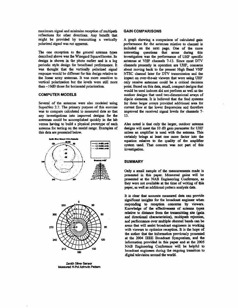
COMPUTER MODELS
Several of the antennas were, also modeled using SuperNec 2.7. The Primary purpose of this exercise was to compare calculated to measured data so that any investigations into improved designs for the antennas could be accomplished quickly in the lab versus having to build a physical prototype of each antennu for testing on the model range. Ekamples of this data are prscnted below.
0
180
GAIN COMPARISONS
A graph showing a comparison of calculated gain performance for the antennas relative to channel is included 011 the next page. Onc of the more interesting questions that arose during this investigation was the perfonnance of UHF specific antennas at VHF channels 7-13. Since most DTV channels presently in operation arc W, wncems about moving back to the present High Baud VHF NTSC channel later for DTV transmission and the in@ on over-theair viewers that were using UHF only raxive antennas could be a critical decision point Based on this data, small, compact designs that would be used indoors did not perform as well as the outdoor designs that used two-dimensional arrays of dipole elements. It is believed that the feed systcms for these larger arrays provided additional ma for cnmmt flow at the lower fiequenciea and therefore improved the received signal levels for channels 7- 13.
Also noted is that only the I-, outdoor antenna designs will meet the 10 dB gain parameter for UHF unless an amplifier is used with the antenna. This certainly brings at lcast one more hctor into the equation relative to the quality of the amplifier system used That concern was not part of this inVestigation.
SUMMARY
Only a small sample of the mea6uTrments made is presented in tbis paper. M d gains will be presented at the NAB Engineering Cod-, as they were not available at the time of Writing of tbis paper, as well as additional pattun analysis data.
It is clear that auauate meamxed dsta can provide significant insight8 for the broadoast engineer wben responding to rccqnion CoIWllp by vi.5wers. Knowledge of the e w v - of antenna (ypes n M v e to distalbx fium the tlmsnli- SiK! (gain and directional chsractcriStica), multipntb rejection, and pufomrance over multiple channel bands can be areas that will assist broadcast enginem in working with viewers to optimize reception. It is the hope of the author that the idomtion previously presented at the 2004 IEEE Broadcast Symposium, and the information provided in this paper and at the 2005 NAB Enginwing Conference will be helpful to broadcast engineers duMg the ongoing transition to digital television around the world
Zenith Silver Sowor Mawred KFW Admuth Paltern
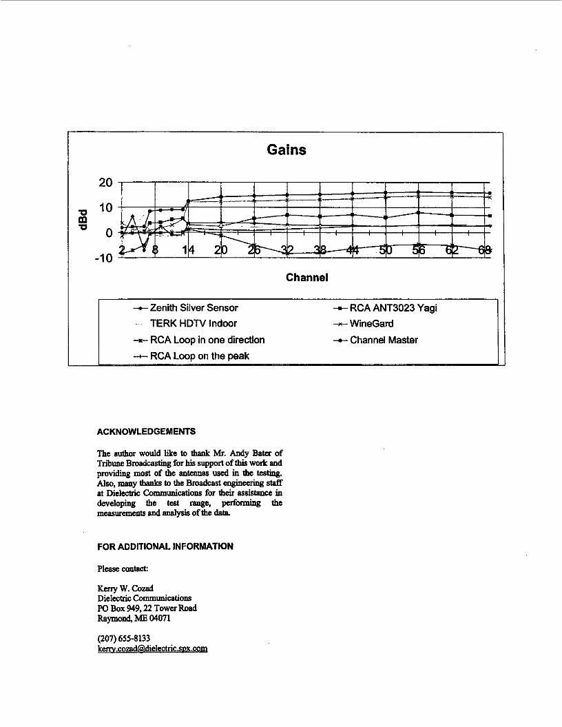
Gains
20
U 10 m ' O O
-1 0 Channel
-Zenith Silver Sensor -.- RCA ANT3023 Yagi
-o- Channel Master TERK HDTV Indoor + WineGard
-r- RCA Loop in one direction
ACKNOWLEDGEMENTS
The &or would like to thaak Mr. Andy Batu of Tribune Broadcasting for bis supper( of this work and pmvidii most of the antennas used in the testing. Also, many thanks to the Broadcast engineering s k f f at Dielectric Communications for their assistance in developing the test range, puforming the rneasurcmenta and analysis of the data
FOR ADDITIONAL INFORMATION
Please mw
KcnyW.cozad Dielectric Communications PO Box 949,22 Tower Road Raymnoa, ME 04071
(207) 655-8133 kenv.cozadhdie~e&ic.sDx.~
ATTACHMENT 3
I 076 IEEE Tmssctiona m Cmsuma Elauonics, Vol. 50, No. 4, NOVEMBER 2004
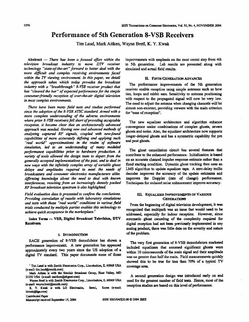
Performance of 5th Generation 8-VSB Receivers Tim Laud, Mark Aitken, Wayne Bretl, K. Y. Kwak
Abstract - There has been o focused eflort within the improvements with emphasis on the most recent step fium 4th television broadcast indusfty to move D W receiver to 5th generation. Lab results are presented along with technology “state-of-the-art” fonvod to better deal with the simulated and acatal field d t s . more d%lt and complex receiving environments faced within the TV viewing ekironment. I; this paper, we detail the approach taken which todoy provides the broadcast induriy with o “breakthrough” 8-VSB receiver product thai has ’%leared the bar” of expectedperjrmonce for the simple commer-friendly reception of over-the-air digital television in most complex environments.
There have been many field tests ond studies performed since the adoption of the &ySB ATSCstondad. Armed with a more complete understonding of the adverse environments where prior 8-VSB receivers fell short ofproviding acceptable reception, it become clear that on architecturolly advanced approach was needed. Having new ond advanced methoak of analyzing coptured RF signals, coupled with new-found copobilities of more accurately defining and appbing such “real world” ooomimations in the realm of so-
11. FIFTH GENERATION ADVANCES The performance improvements of the 5th generation
receiver enable reception using simple antennas such as bow ties, loops and rabbit ears. Sensitivity to antenna positioning with respect to the propagated signal will now be very low. The need to adjust the antenna when changing channels will be almost non-exismt, providing viewen with the main criterion for “ease of reception”.
The new equaliw architecture and algorithm enhance convergence under combinations of complex ghosts, mere ghosts and noise. Also, the equalizer architecture now supporn longerdelayed ghosts and has a symmekic capabiiity for pre and post ghosts. -. -~
simulation, led to an understanding of many modeled peformance copabilitier prior to hardware production. A variety of tools allowed the design team to depan from the generally accepted implementotions of the post, and to deal in new wavs with the infiniteh comolex arrm of variable ghost
The ghost circuit has several features contribute to the enhanced pef iomce . Initialization is based On an accurate k d s e response estimate d ~ e r a fixed starting condition. Dynamic ghost baclting then use8 an
delays *and ampliides ;equi& to mie; the nee& of LMS d g o r i h to update equaliza taps. A =-delay trellis broadcarters and consumer eleclmnicr monufwturers olike dewder improves the sccuracy of the update estimates and Afirming knowledge about the need to deal with known unproves the Doppler (rate of change) performance. inteferences. resulting f m m an increasingly densely packed Techniques for reduced noise enhancement improve ~ccure.cy. RF brwdcnst television spectnim is also highlighted
Field evaluation data is presented to confirm the conclusions. Providing correlation of results with laboratory simulations
111. EQUALIZER IMPROVEMENTS OF VIWOUS GENERATIONS
ond teslrwith those “&I world conditions in various field mals conducted by multiple parties enables this technology to achieve quick acceptance in the mmkeplace.’
From the be*ing of developmnf it was that mdtipath was an that need to be
a d M . esnffiiallv for indoor rcccntioa However. since Index Tunu - VSB, Digital Broadcast Television, DTV automatic ghost canding of the complexity q u i d for
digital nccption had not been previously implemented in any analog product, thm was little data on the severity and nature
Recdven
I. INTRODUCTION of the problem
showed thk to be truC fM less than 70% of 8 typical TV coverage area ‘ Tim Lmd is with h i t h El-ia Cap.. Linsobshirc, IL @M69 USA
Mmk Aitken is with mC SinGIair B d Gmnb Hunt Valley, MD
W a r n Bntl is mth Zenith Eleommia Gorp.. L incoWi IL 60069 USA
K . Y . K v v l l l r i r w i m L G E k c ~ . ScOvL Kmca(e-ouil:
(*mail: Iim.l-lb.mm)
21030 USA (d ~~~~)
(wuil: [email protected])
M k - 4 caatribntcd Rpr
A second generation design WBS intmduced early on and used for the greatest number of field tests. Hence, most of the reception studies are based on this level of p~rfo-.
~ p l r e c e k d ~ I5.2OW MlP8 3063/04/SZO.W 0 2W4 IEEE
T. Luul et 11.: Pdomwkx of 5th hcnt ion 8-VSB Recdva
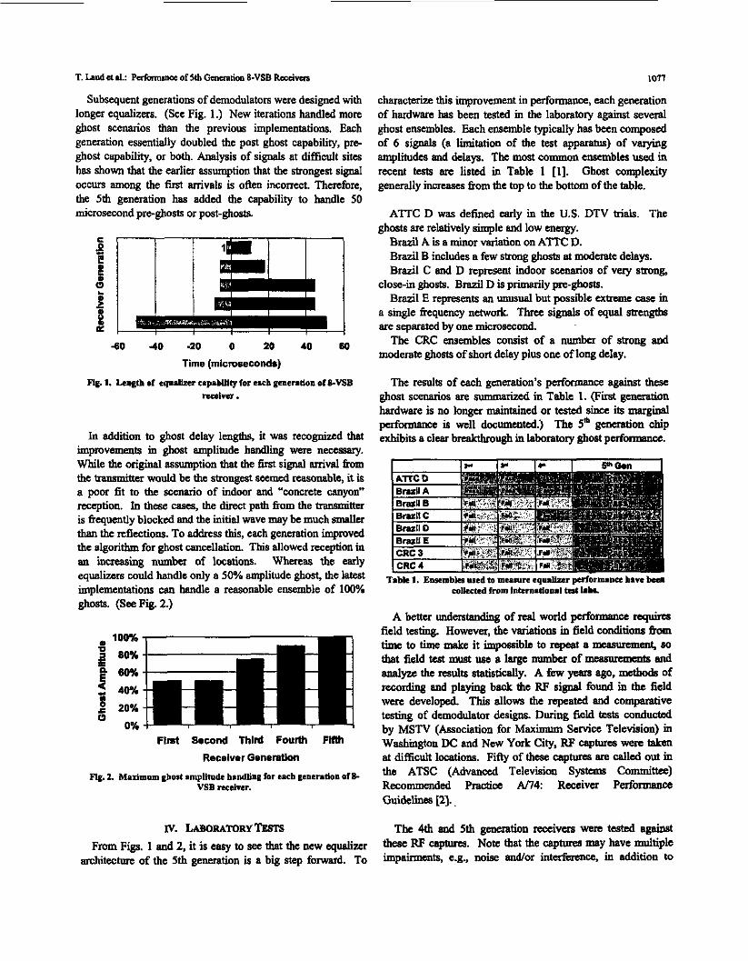
Subsequent generations of demodulators were designed with longer equalizers. (See Fig. 1.) New iterations handled more ghost scenarios than the previous implementations. Each generation emt ia l ly doubled the post ghost capability, pre- ghost capability, or both. Analysis of signals at difficult sites has shown that the earlier assumption that the strongest signal occurs among the first arrivals is often incorrect. Therefore, the 5th generation has added the capability to handle 50 microsecond pre-ghosts or post-ghosts.
i o n
characterk this improvement in performance, each generation of hardware has been tested in the laboratory against several ghost ensembles. Each ensemble typically has been composed of 6 signals (a l i t a t i o n of the test apparatus) of varying amplitudes and delays. The most common ensembles used in recent tests ere listed in Table 1 [I]. Ghost complexity generally increases fiom the top to the bottom of the table.
ATTC D was defined early in the US. DTV hi&. The ghosts are relatively simple and low energy.
Brazil A is a minor variation on ATM: D. Brazil B include a few strong ghosts at moderate delays. Brazil C and D represent indoor scenarios of very smng,
Brazil E represents an unusual but possible extreme case in close-in ghosts. Brazil D is primarily pre-ghosts.
a single ikquency netwok Three signals of equal are separated by one microsecond
moderate ghosts of short delay plus one of long delay. The CRC ensembles consist of a number of strong and
The results of each generation's perfonnauce against these ghost scenarios are summarized in Table 1. ( F i i gencration hardware is no longer maintained or tested since ik marginal performance is well docummted.) The 5' generation chip exhibits a clear breakthrough in laboratory ghost performance.
C 0 - 3 a S I 1 1 - 1
4 0 -40 -20 0 20 40 60
Time (mkroceconde) Fig. 1. LenLfb of rqusbr cspblllty for rich gcnentlon of SVSB
d w r .
In addition to ghost delay lengths. it was recognized that improvements in glmst amplitude h d m g were necessary. While the original assumption that the 6rst signal anival h n the transmitter would be thc strongest s e e d reasonable, it is a poor fit to the s&o of indoor and "concrete canyon" reception. In thcse cases, the direct path from the transmitter is frequently blocked and the initial wave may be much s d l c r than the reflections. To address this, each generation improved the algorithm for ghost cancellation. This allowed reception in au mueasing numbm of locations. Whercas the early e q d i could handle only a 50% amplitude ghost, the latest implementations can handle a reasonable ensemble of 100% ghosts. (See Fig. 2.)
Flnt Second Thlrd Fourth Flllh Receiver GeneratLon
w. LABORATORYTESTS From Figs. 1 and 2, it is easy to see that the new equalizrr
Table 1. Enrrmblrs osed to measure equdber p r f o r m m ham ban EOUICtrd from IntSm.Iioul M 1 . k
A better undeRtanding of red world pfonnancc r e q u h field testing. However, the variations in field conditions from time to time make it impossible to q a t amcasurement, M)
that field test must use a large number of memmnmk and dyu : the Wdk statistidy. A few ycsrS ago, mthods Of recording and playing back the W s i g d found in the field were developed This allows the repeated and comparative testing of demodulator designs. During field tests conducted by MSTV (Association for Maximum Service Television) in Washimgton DC and New Yo& City, RF caplurea wese taken at difficult locations. Fitly of the8e caplurea are called out in the ATSC (Advanced Television System9 committee) Recommended M c e A i l 4 Recciva Performance Guidelines [2].
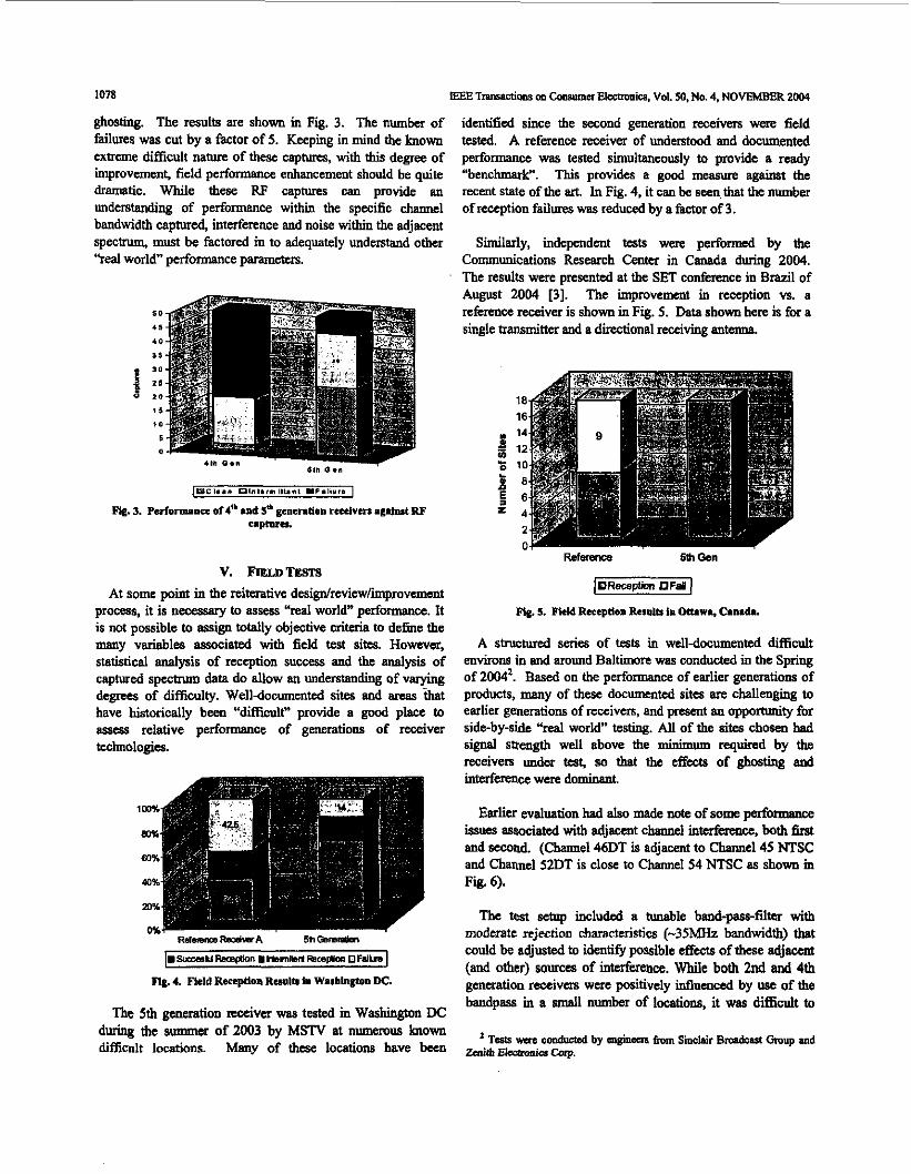
The 4th and 5th generation reccivcrs were tcstul against these Rp captures. Note tbat the caplum may have multiple
d t e c t u r e of the 5th generation is a big step f o d . To h-B, ea., noise a d o r interfcrsncc, in addition to
1078 EEE Tran~nctims m cons- Elcomnics. Vol. 50, No. 4, NOVEMBER 2004
ghosting. The results are shown in Fig. 3. The number of failures was cut by a factor of 5. Keeping in mind the known extreme difficult ~ f u r e of these captures, with this degree of improvemenL field performance enhancement should be quite dramatic. While these RF captures can provide an understanding of performance within the specific channel bandwidth captured, interference and noise within the adjacent spectrum, must be factored in to adequately understand other ''real world" performance parameters.
V. FreLonrsrS At some point in the reitaative design/rcview/improvcmcnt
process, it is nemssary to asses "real world" perfomawe. It is not possible to assign totally objeaive criteria to d e h e the many variables associated with field test sites. However, statistical analysis of reception success and thc analysis of captured spcctnrm data do allow an understanding of varying degrees of difficulty. Well-documented sites and areas -that have historically been "difficult" provide a good place to assess relative performance of generations of receiver technologies.
""1
5m oemam ~ ~ u n a t l l ~ s o a y t i o n ~ m m ~ m s r a a OF-
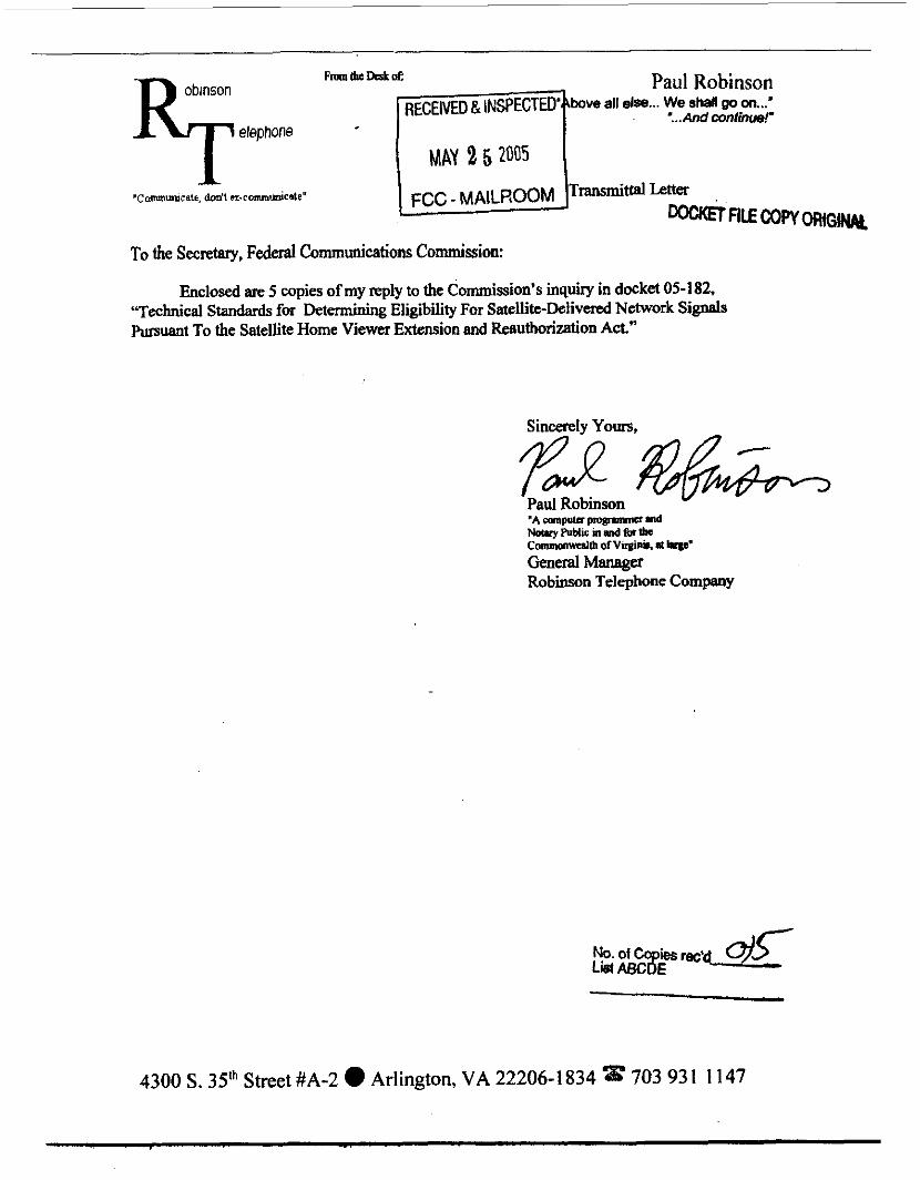
Fig. 4. Field Rerrptlon RMlo in Washlngtom DC.
The 5th perat ion receiver was tested in Washington DC during the summer of 2003 by MSTV at numerous known difficult locations. Many of these locations have bcen
identified since the m u d generation receivers were field tested. A reference receiver of understood and documented performance was tested simultaneously to provide a ready “benchmark". This provides a gocd measure against the recent state of the art. In Fig. 4, it can be seen that the number of reception failures was reduced by a factor of 3.
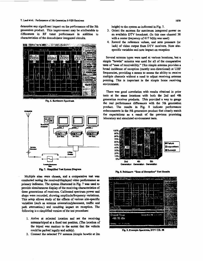
Similarly, independent tests wexe performed by the Communications Research Center in Canada during 2004. The result?. were presented at tbe SET conference in Brazil of August 2004 [3]. The improvement in reception vs. a reference receiver is shown in Fig. 5. Data shown here is for a single kansmittex and a directional receiving antenua.
&I& 5. Field Reccptlon ResUlb 1. Ottawa, Csmad..
A structured series of tests in welldocumented difficult environs in and around Baltimore was conducted in the Spring of 20M2. Based on the performance of earlier generations of products, many of these documented sites are challenging to earlier generations of receivers, and present an oppoaunity for side-by-side "real world" testing. All of the sites chosen bad signal seength well above the minimum required by the receivers undm test, so that the effects of ghosting and interference were dominant.
Earlier evaluation bad also made note of some performaace issues associated with adjacent channel interheme, both 6rst and second. (Channel 46DT is adjacent to Channel 45 NTSC and Channel 52DT is close to Channel 54 NTSC as shown in Fig. 6).
The tost saup included a lunable band-pawfilter with moderate rejection characteristics (-35MHz bandwidth) that could be adjusted to identify possible e&cts of these adjacent (and other) sources of intnfereace. While both 2nd and 4th generation raxivem were positively influenced by use of the bandpass in a small numbex of locations, it was difEcult to
Tests wn 00DduCtcd by ooginkn from Sinclair Brmdoul Omup and ZenithKIwmmKa ' CLT.
T. Lud a d.: ~aforrmDcc Of 51b "io0 &vsB b d W 1079
determine any significant impact on the performance of the 5th generation product. This improvement may be attributable to 3. Orient the antenna for maximum integrated power on differences in RF tuner performance m addition to an available DTV broadcast. (In this case channel 38 characteristics of the demodulator integrated circuits. with a center 6equency of 617 MHz was used)
4. Record the reference values, and note pmence (or lack) of video output fium DTV receivers. Note site- specific variables and note impact on reception
height) to the system as indicated m Fig. 7.
Several autcnna types wcre wed at varim locations, but a simple "bowtie" antenna WBS used for all of the comparative tests of "ease of receivability." This simple antenna provides a broad incidence of reception (mostly non-direCtional) at UHF frequencies, providing a means to assess the ability to receive multiple channcls without a need to adjust receiving antenna pointing. This is important in the simple home receiving environment
There was good correlation with results obtained in prior tests at the snme locations with both the 2nd and 4th generation receivex products. This provided a way to gauge the real performance differences with the 5th gemration product. The mults in Fig. 8 indicatc performance enhancements in the 5th generation product that closely math the expectations M a result of the previous promising laboratory and 8imulated environment tests.
lCQ% 90%
70% ea% 50% 40% 30% 20% 10% Mc
wm
Multiple sites vme chosen, and a cornpmhve teeat was conducted noting the receivddisplayed video performance a8 primary indicator. The sptem illustrated in Fig. 7 was uscd to provide sisnulltanews display of the seceiving cha~~~c~aticos of three generations of receivers. Calibrated spectrum power and shape were recorded, showing amplituddfrequency variations. This setup allows study of the effects of various site-specific variabtcs (such as antem orientatiodplacemcnt, M c and path attmuation) and resulting impact on reception The following is a simplified version of the test procedure:
1. Arrive et selected location and set the receiving antennaltripod at a fixed test position. (The location of the tripod was random to the extent that the vchicle could be parked legally and safely).
2. Connect the selected N antmum (simple bowtie at 2m

1080
ng. lo. Example sprmm, on CH. sa
Even in some of the most difficult sites, with multipath very evident in the specbum (Fig. 9 and Fig. lo), reception was possible with the 5' generation receiver.
nmothy Laud (M'74) is a Ssnia Mmbcr of the Tcobnical Suff for h i t h EIsctmniu Caprmtim. Tim .tlpdcd M u e Univcnity where bc - i d his BSEE in 1975 and MSB6 in 1976. After a brief paid d Mc+orols, Tun joined thc zcrrilh R&D lean in 1980. Hc har h inrn1w.d in Ihs development of VSB and E-VSB r i w thcir iwlioos. VI. FUTUREENHANCEMENTS
Improvements in receiver performance beyond fifth generution are still possible. Improvements are planned for Mark A. Altlrm is Dir. of A d v d Technology, Shwlair equalizm convergence speed, particularly to address the Bmdcut omup. EdwlOd u Sprinsftcld TdmiuI
Mpn at Rmssclner Polytechnic Innihtlc. he repmads portable enVimnment . Adjacent channel interference can be addressed in two ways. Changes in tuner AGC methodology SBG within many indurtry related or&anin!icms including can address overload conditions experienced with the more A m . M,. Aitkm is a manba of A F E E d IEEE, densely packed broadcast spectrum. The effects on reception involved with a d v d digital lciMsi00 SyStemS d c s i
of digital stations can be reduced by operating them at 111 liccnsed power, especially when thcy arc in a spechwn with
camnnmity Collcp with continuing edudm in Ea&
and implcmmlltioo.
powerful adjacent or nearly adjacent analog stations.
VU. CONCLUSION Because of the need to free up spectrum for a variety of
interests and uses, an increasing burden has been placed on all involved in the FCC mandated DTV transition. Because of the "all or nothing" nature of digital reception, digital TV must pmvide excellent reception even where analog reception is poor, in order to facilitate the transition for thc large number of receivers that use over-the air Rccption This is beyond the quirements originally proposed at the inception of digital television, but it is being met by 5' generation designs.
Development of the successive generations of demodulators has depmdsd on a c w p t i v e effort of broadcastas and receiver designers to better understand expectations, ideutify the real world problems associated with digital terrestrial transmissiodreception and define test protocols that more fdly represent that real world (for example the ATSC recommended practice An4).
Proper matching of the application design efforts to the discovmd realities of digital terrcshial reception has resulted in 5' generation hardware that clearly supports identified
Paul Robinson bow all el se... We shall QO on...’
....And continue!’
MAY 2 5 2005
’Cammmucats. don’t n . c m u m c a t e ” b t tm -flECOWORiGkJ&
To the Secretary, Fedend Communications Commission:
Enclosed are 5 copies of my reply to the Commission’s inquiry in docket 05-182, “Technical Standards for Determining Eligibility For Satellite-Delivered Network Si&s Pursuant To the Satellite Home Viewer Extension and Reauthorizxdon Act-”
4300 S. 3Sth Street #A-2 0 Arlington, VA 22206-1834 703 93 I 1147


![01-LGE EMS_company profile_PA1 [修復]](https://img.pdfslide.us/doc/110x75/577ce6e41a28abf10393df0c/01-lge-emscompany-profilepa1-.jpg)