Embed Size (px)
Citation preview

Calhoun: The NPS Institutional Archive
Reports and Technical Reports All Technical Reports Collection
2003-09
Test and evaluation of the Ballistic
Missile Defense System: FY03 progress report
Michael, James Bret
Monterey, California. Naval Postgraduate School
http://hdl.handle.net/10945/500
CORE Metadata, citation and similar papers at core.ac.uk
Provided by Calhoun, Institutional Archive of the Naval Postgraduate School

NPS-CS-03-007
NAVAL POSTGRADUATE SCHOOL Center for Joint Services Electronic Warfare
MONTEREY, CALIFORNIA
Approved for public release; distribution is unlimited.
Prepared for: Missile Defense Agency 7100 Defense Pentagon Washington, D.C. 20301-7100
Test and Evaluation of the Ballistic Missile Defense System
FY03 Progress Report
By
James Bret Michael, Phillip E. Pace, Man-Tak Shing, Murali Tummala
Joel Babbitt, Michael Miklaski, David Weller
September 2003

NAVAL POSTGRADUATE SCHOOL Monterey, California 93943-5000
RADM David R. Ellison Richard S. Elster Superintendent Provost
This report was prepared for Missile Defense Agency and funded by the Missile Defense Agency. Reproduction of all or part of this report is authorized. This report was prepared by: Reviewed by: ________________________ ________________________ James Bret Michael, Associate Professor Phillip E. Pace, Professor & Director Department of Computer Science Center for Joint Service Electronic Warfare Reviewed by: Released by: ________________________ ___________________________ Peter J. Denning, Chairman and Professor Leonard A. Ferrari Department of Computer Science Associate Provost and Dean of Research

REPORT DOCUMENTATION PAGE
Form Approved
OMB NO. 0704-0188
Public Reporting burden for this collection of information is estimated to average 1 hour per response, including the time for reviewing instructions, searching existing data sources, gathering and maintaining the data needed, and completing and reviewing the collection of information. Send comment regarding this burden estimates or any other aspect of this collection of information, including suggestions for reducing this burden, to Washington Headquarters Services, Directorate for information Operations and Reports, 1215 Jefferson Davis Highway, Suite 1204, Arlington, VA 22202-4302, and to the Office of Management and Budget, Paperwork Reduction Project (0704-0188,) Washington, DC 20503. 1. AGENCY USE ONLY ( Leave Blank)
2. REPORT DATE
9/30/2003
3. REPORT TYPE AND DATES COVERED
Progress Report 10/01/2002 – 09/30/2003
4. TITLE AND SUBTITLE Test and Evaluation of the Ballistic Missile Defense System –
Progress Report (10/01/2002 – 09/30/2003)
5. FUNDING NUMBERS
BMDO01342923172
6. AUTHOR(S)
J.B. Michael, P. Pace, M. Shing, M. Tummala J. Babbitt, M. Miklaski, D. Weller
7. PERFORMING ORGANIZATION NAME(S) AND ADDRESS(ES) Center for Joint Services Electronic Warfare, Naval Postgraduate School, Monterey, CA 93943
8. PERFORMING ORGANIZATION REPORT NUMBER NPS-CS-03-007
9. SPONSORING / MONITORING AGENCY NAME(S) AND ADDRESS(ES)
Missile Defense Agency 7100 Defense Pentagon Washington, DC 20301-7100
10. SPONSORING / MONITORING AGENCY REPORT NUMBER
11. SUPPLEMENTARY NOTES The views, opinions and/or findings contained in this report are those of the author(s) and should not be construed as an official
Missile Defense Agency position, policy or decision, unless so designated by other documentation. 12 a. DISTRIBUTION / AVAILABILITY STATEMENT Approved for public release; distribution unlimited.
12 b. DISTRIBUTION CODE
13. ABSTRACT (Maximum 200 words)
This report summarizes the work done in FY03 to develop a systematic engineering-based approach for constructing a high-level architecture for a Ballistic Missile Defense System (BMDS). We developed six UML use cases to identify the external agents and systems that are involved in a typical missile-defense scenario. Based on these use cases, we developed the top level of a distributed architecture of a BMDS and conducted simulation studies to analyze the network requirements to support such an architecture. We also developed a physical model to analyze the sensor requirements to successfully detect and track a ballistic missile throughout the boost phase.
. 14. SUBJECT TERMS
Missile Defense, Requirements Analysis, Distributed Architecture, Network Simulations, Sensors
15. NUMBER OF PAGES 24
16. PRICE CODE
17. SECURITY CLASSIFICATION OR REPORT
UNCLASSIFIED
18. SECURITY CLASSIFICATION ON THIS PAGE
UNCLASSIFIED
19. SECURITY CLASSIFICATION OF ABSTRACT
UNCLASSIFIED
20. LIMITATION OF ABSTRACT
UL NSN 7540-01-280-5500 Standard Form 298 (Rev.2-89) Prescribed by ANSI Std. 239-18
298-102

THIS PAGE IS INTENTIONALLY LEFT BLANK

1
Progress Report
Test and Evaluation of the Ballistic Missile Defense System
10/1/2002 – 9/30/2003
Abstract This report summarizes the work done in FY03 to develop a systematic engineering-based approach for constructing a high-level architecture for a Ballistic Missile Defense System (BMDS). We developed six UML use cases to identify the external agents and systems that are involved in a typical missile-defense scenario. Based on these use cases, we developed the top level of a distributed architecture of a BMDS and conducted simulation studies to analyze the network requirements to support such an architecture. We also developed a physical model to analyze the sensor requirements to successfully detect and track a ballistic missile throughout the boost phase. 1. Statement of the Problem Studied: This project addresses the DoD’s needs to develop a system to defend the forces and territories of the United States, its allies, and friends against exo-atmospheric ballistic missile threats. The Missile Defense Agency (MDA) will accomplish this mission by developing a layered defense that employs complementary sensors and weapons to engage threat targets by land, sea, air, or space in the boost, midcourse, and terminal phases of flight, and incrementally deploying that capability. In parallel, sensor suites and battle management and command and control will be developed to form the backbone of the Ballistic Missile Defense System (BMDS). The objective of the project is to develop a systematic engineering-based approach for constructing a high-level architecture for a specific system-of-systems: the Ballistic Missile Defense System (BMDS).
2. Summary of Important Results: In order to develop the correct architecture and build such a system, we are developing a list of requirements and constraints, which will help MDA to ensure that they both build the right system, and that they build it right. These requirements and constraints will provide a solid foundation for evaluating proposed system architectures.
2.1 Use case Analysis
We developed six UML use cases to identify the external agents and systems that are involved in a typical missile-defense scenario and the necessary interactions between these entities: 1. Detect Potential Threat Ballistic Missile -
The goal of this use case is to detect possible threat ballistic missiles, and push the track data onto the sensor net.
2. Generate and transmit a local track - This is a sub-use case of 1. The goal of this use case is to have a sensor generate a local track based on valid detection parameters of the sensor.
3. Cooperatively Track and Classify Threat Ballistic Missiles - The goal of this use case is to identify and type-classify the threat ballistic missiles, develop fire-quality tracks for engagement solutions, and forward target track list to Weapons Net.
2
4. Cooperative Weapons Assignment - The goal of this use case is to assign targets to weapons via cooperative target bidding.
5. Engage Targets - The goal of this use case is to engage threat ballistic missile.
6. Assess Kill - The goal of this use case is to determine the kill status of the threat ballistic missile.
Details of the use cases can be found in Appendix 1.
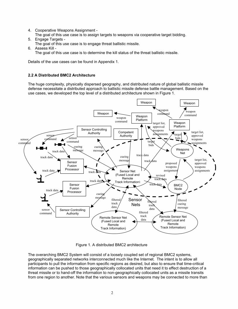
2.2 A Distributed BMC2 Architecture
The huge complexity, physically dispersed geography, and distributed nature of global ballistic missile defense necessitate a distributed approach to ballistic missile defense battle management. Based on the use cases, we developed the top level of a distributed architecture shown in Figure 1.
The overarching BMC2 System will consist of a loosely coupled set of regional BMC2 systems, geographically separated networks interconnected much like the Internet. The intent is to allow all participants to pull the information from specific regions as desired, but also to ensure that time-critical information can be pushed to those geographically collocated units that need it to effect destruction of a threat missile or to hand-off the information to non-geographically collocated units as a missile transits from one region to another. Note that the various sensors and weapons may be connected to more than
Sensor Fusion
Processor Sensor Net (Fused Local and
Remote Track Information)
BMC2 Node
Weapon
Remote Sensor Net (Fused Local and
Remote Track Information)
Weapons Net
Sensor Fusion
Processor
Remote Sensor Net (Fused Local and
Remote Track Information)
SensorNets
Figure 1. A distributed BMC2 architecture
WeaponPlatform
Weapon Weapon
track data
CompetentAuthority
Sensor Controlling Authority
Sensor ControllingAuthority
Weapon Platform
track data
track data
track data
track data
track data
cueing message
cueing message
cueing message
cueing message
filteredtrack data
sensor command
sensor command
sensor command sensor
command
filteredtrackdata
filteredtrackdata
track data
revised track data
filtered cueing message
target list, approved weapons assignments
proposed weapons
assignment
target bids
target bids
track data
track data
target list, approved weapons assignments
target list, approved weapons assignments
weapon command
weapon command
weapon command

3
one regional BMC2 system via proxy. The advantage is that geographic location is a “don’t care” in that context. The real-time nature of the battle requires that all sensor information be local to fight the battle. As the missile continues in its flight, the real-time battle management, together with some of the sensors and weapons, will handover to another regional BMC2 system. The use of the Broker pattern1 will ease the handover of the assets from one region to another. By distributing the networks in this manner, information regarding any ballistic missile threat is available and accessible to all participants as desired, but will not overburden the network by having all the information presented to all units all the time; this will provide increased availability of data; more localized control, and improved response times of the units to counter the threat. Thus, units subscribe to the network with their addresses being available in routing tables with knowledge of the geographic location of the unit so that only data and information relevant to a particular unit (or region) is forwarded to that unit (or region). For example, fire-control data from another theater or region may not be useful and hence will stay local, while threat information from other theaters or regions will probably serve as situational awareness and make available to other regions.
Each regional BMC2 system consists of three major sub-systems: a Sensor Net, a Weapons Net and a BMC2 node. • Sensor Net refers to a distributed system that provides the sharing of track data among Sensor
Fusion Processors2, Weapons Net, Weapon Platforms and the BMC2 Node. It supports a distributed track data-bidding process through which the Sensor Fusion Processors collaboratively perform track correlation along with fusion to improve the quality of the integrated air picture. It also allows the broadcasting of cueing messages among Competent Authorities3 and the Sensor Controlling Authority4.
• Weapons Net refers to a distributed system for target bidding. It manages a list of targets waiting
to be engaged by the Ballistic Missile Defense System, and coordinates cooperative weapons assignments (i.e., the pairing of appropriate weapons with targets) based on the bids (i.e., figure of merits that are based on many factors such as the defended area, predicted impact point, threat type, health and status of weapons, current engagements) submitted by individual weapons platforms, and policies, rules of engagement and manual overrides from the battle manager.
• BMC2 Node refers to the automation for supporting the BMC2 functions. It provides the interface
for battle managers to create/modify the prioritized target list, set the initial weapons authorizations and other rules of engagement, and to monitor the engagement to its conclusion given that it may have to reassign the track to another weapon. The term “node” implies that the processing unit can be a component of a smart Sensor Net.
In addition, we have identified the following twelve areas for further study: • Simulation studies and algorithm designs for distributed weapon cooperative assignment; • Analysis and simulation studies for data requirements and management for successful weapons
engagement; • Analysis and simulation studies for sensor capabilities for continuous tracking of ballistic missiles 1 For a detailed treatment of the Broker pattern, see F. Buschmann et al., Pattern-Oriented Software
Architecture: A system of Patterns (New York: John Wiley & Sons, 1996). 2 Sensor Fusion Processor means the processor (which may reside together with the sensor) that has
sensor fusion capability using information from its associated sensors and remote track information from the Sensor Net, where a sensor includes both the detection hardware and the local processor with capability to create local track data, but not the sensor fusion capability.
3 Competent Authority means any INTEL source external to the Missile Defense System. 4 Sensor Controlling Authority means the agency that owns the sensor assets.

4
through the kill chain; • Notional architectures and dynamic behavior specification for battle management systems; • Comparison of different models of cooperation (e.g., low-cooperative vs. high-cooperative) among
BMC2 elements; • System-level fault tolerance requirements and techniques for battle management systems; • Security requirements and techniques for battle management systems; • Communication and network requirements for battle management systems; • Automation to support handover of control for battle management; • Correlation algorithms to include IR/RF information and kill assessment; • Techniques to support automated consequence management and automated battle management
(i.e.; no human-in-the-loop); • Validation techniques for battle management systems. 2.3 Simulation Study for Network Requirements The regional BMC2 will be supported by three integrated sub-networks: a Sensor Net, a Weapons Net, and a Command and Control (C2) Net emulating a geographical intranet. The primary justification for the division along functional lines is that the data, in its entirety, flowing across each network may not be relevant to the others. For instance, the specific radar parametric data derived from the Sensors is critical for use in the Weapons Net but is not necessary for C2; only the particular missile track information, like a Link-16 track, is pertinent. Conversely, intelligence information, such as ELINT or HUMINT regarding the location of a missile that is necessary for C2 is not critical for the actual employment of a weapon system or to conduct sensor tracking. Therefore, the data that is critical for each network will be determined and made available, but information that is not critical for the functional area will not be provided, thus preventing excessive overload on that particular network that doesn’t require the data.
At the Sensor and Weapons Net, the message format will need to be binary and in a standardized format to reduce overhead and time latency and ensure time-critical data is made available to the participating units that need it. The C2 network, by necessity, will consist of more than just track data to include, USMTF messages, intelligence data from varying sources, etc. and as such will need to incorporate middleware such as XML or CORBA, as well as legacy sensor and weapons systems, to keep the implementation independent of the platform.
The BMC2 System will consist of various communication mediums to ensure complete network connectivity. Currently, MDA is considering fiber-optic cable for the terrestrial elements of the network and will allow large throughput of data. However for the air, sea, and space-based elements the only possible means for data transmission is by RF energy. For space-based systems UHF, EHF, or SHF can be utilized and the obvious choice would be the higher frequencies for greater data throughput. Sea-based can also utilize these frequency ranges, however due to the higher frequencies requiring large antenna sizes, only the larger combatants can participate at the EHF/SHF level. For air-based units the only viable choice for data transmission is on UHF due to smaller antenna sizes with a high enough data throughput to be effective. The bottom line is whatever platform the servers reside on, they will need to be capable of transmitting and receiving data from all sources.

5
As mentioned previously, each of the nets are divided along functional lines and will consist of the data necessary to conduct their primary mission. The C2 Net will be interfaced with the Sensor and Weapons Net to provide C2 functionality for the direction and employment of each of these systems. The sensors will be cued by command inputs from the Sensor Net via the C2 Net and track data will be received for distribution to higher and adjacent command elements interfaced within the C2 Net and BMC2 system. Weapons systems assignment shall be directed for employment based on the tracking-data inputs from the Sensor Net, weapons availability from the Weapons Net, and the previously mentioned aspects of the weapons tasking logic. The C2 Net will be interfaced with higher and adjacent commands in the BMC2 system for coordination and information exchange, such as the hand-off of tracks, in the prosecution of threat ballistic missiles.
The Weapons Net will encompass all participating weapons systems. A bidding process shall occur for the employment of weapons on specifically designated targets provided by the Sensor Net. The weapons bidding process will be the basis of weapons assignment, thus precluding expending multiple weapons from different weapons platforms on one target. As envisioned, each weapons system will evaluate the tracks provided by the Sensor Net, determine a numerical value based on the trajectory of the missile and its evaluation of the probability of kill and then places a bid. After a given period of time, the bidding will be locked and a weapons assignment (i.e., the pairing of weapons and targets) will be made, perhaps using a two-phase commit protocol. Each weapon system will continue to evaluate the target in the eventuality that the weapon misses or does not completely destroy the target. If the target is destroyed the process is complete, else the bidding process starts anew. The battle manager continuously oversees the whole process, following each track through the entire engagement process. The Sensor Net consists of netting all of the available sensors for the detection of a ballistic missile in a regional BMC2 system. Each sensor, as it develops a track on a ballistic missile, will transmit the track to a Sensor Fusion Processor. The tracks that are developed and transmitted by the sensors will carry a timestamp along with the target’s parametric data so that the Sensor Fusion Processor will able to utilize the most current information with which to update the track. At the Sensor Fusion Processor, the data from its local sensor sources will go through an initial discrimination scheme. A track table will need to be maintained on each contact and as each track report arrives it will need to be correlated based both on an evaluation of the contact current positional status in relation to tracks from other sensors, and a comparison of its current position in relation to a calculated predictive parametric behavior. This will ensure that the contact is valid and can be updated by the most current source, and validate that it is the actual missile and not a decoy or perhaps another missile in close proximity. Once the missile contact is validated, the Sensor Fusion Processor will develop a single track containing the pertinent target data and a unique identifier. The fused track will be pushed onto the Sensor Net for utilization by all participating units. The pertinent parametric data will also be pushed to the Weapons Net for weapons system utilization and weapons bidding. The track data will be also pushed to the C2 Net for situational awareness and command and control decision-making. We developed a simulation based on Use Case 1 “Detecting a Threat Ballistic Missile” and Use Case 1.1 “Generating and Transmitting a Track” using OMNET++ [14]. The purpose of this simulation is to develop a basic baseline simulation to determine the response time of the network, which can be expanded for further use in determining the feasibility of differing variables within the Sensor Net. In this simulation there is a space-based IR satellite in geo-synchronous orbit, 25000nm altitude, which is capable of detecting the launch of a TBM, a ground-based radar sensor, a TBM flying at an altitude of 150nm, a Sensor Fusion Processor, and a Sensor Net. The variables that were changeable are the overall data rate from the radar to the Sensor Net and the message sizes for the radar track, IR track, and fused track from the Sensor Fusion Processor, as displayed in Figure 2. For the purpose of the simulation, once the IR Satellite Sensor or Ground Radar Sensor detects a hit a track report is forwarded to Sensor Fusion Processor. The Sensor Fusion Processor then waits to receive three consecutive hits to develop a track before forwarding a track report to the Sensor Net.

6
Table 1. Results of simulating Use Case No. 1
Radar Data Rate (bits/sec)
Radar Track Size (bits)
Fused Track Size (bits)
IR Track Size (bits)
Average Response Time (sec)
1 1024000 100000 200000 1000 0.8 2 1440000 100000 200000 10000 0.85 3 2880000 100000 200000 10000 Grows 4 1440000 1000000 2000000 1000 Grows 5 2880000 100000 200000 1000 0.8 6 56600 100000 200000 1000 Grows 7 56600 10000 20000 10000 Slow growth 8 1440000 10000 20000 10000 0.825 9 2880000 100000 100000 100000 Grows
10 1440000 100000 100000 10000 0.85
Figure 2. Display of the UseCase1 Simulation

7
We conducted a parametric analysis using the simulation model. The result of our initial analysis is shown in Table 1. The major data points that were extracted are as follows: 1) The larger message sizes seem to have an adverse influence on the response time of the network. If
the size of the message was larger than the default value, the response time grew rapidly over time. 2) When the message size is small and the data rate high (run Nos. 1, 2, 5, 8, 10), the response time of
the network stabilized between 0.8 and 0.85 seconds. 3) When the message size is small and the data rate low (run No. 7), the response time starts out very
small (below 2 seconds) and increases slowly over time. The primary reason for the larger messages causing excessive delays and incremental growth in the response time is because the Sensor Fusion Processor does not drop messages in this simulation. The Sensor Fusion Processor has to process every message it receives. As the sensors generate messages, the Sensor Fusion Processor begins to queue the backlog of unprocessed messages. We plan to use simulation to explore different strategies to handle the message-overflow problem. One option is to allow the Sensor Fusion Processor to discard older messages based on their timestamps and only utilize the most current ones for the updating of tracks. This may work for simulation; however, this may not be operationally feasible. In the operational world, we do not want to drop sensed data. If it becomes stale, then the system has failed. This becomes a factor in the selection of a real-time approach versus non-real-time. Other option is to process (e.g., discriminate) the data locally and send processed data. We need to determine how to handle data in real-time and not let it ride on a stack as it waits for processing. Fundamentally, we would want to design a system with as great a throughput as feasible with a small enough track message size as possible to keep the response times low. Suffice it to say, that the simulation seems to fit the needs for this study and further pursuit in developing a more robust OMNET simulation for the BMC2 system is in order.
We intend to use simulation to further study the application of distributed algorithms along with the timing and data requirements for cooperative engagement in the weapons network. In particular, we will investigate the technical feasibility of using state-transition triggers rather than messaging in the weapons networks. We also need to investigate the information exchange between battle manager nodes and the interceptors/space-based assets, and the coordination among regional BMC2 systems to achieve handovers and information sharing among nodes. We will study the interface between a node and a sensor/weapon type, in order to capture the details of the interface requirements.
2.4 Analysis of sensor-capability requirements for Ballistic Missile Defense System-of-systems architectures for ballistic missile defense have generally incorporated and relied heavily upon capability-based systems to perform the detection and tracking of ballistic missiles. These legacy systems were developed with specific requirements outside the BMD objective and consequently a use-what-we-have situation is currently being deployed. In other words, no sensor requirements (both RF and IR) have been put forward to assure successful BM intercept.
In this study, we are developing a procedure to derive specific requirements based on several scenario simulation results that also include the sensor network and fusion processing needs. Based on these requirements, we propose to quantify the sensor capabilities that must be present in order to provide a proper intercept and tracking of ballistic missiles. Starting with a scenario of a ballistic missile being launched and engaged by both a forward-based RF sensor and space-based IR sensor, we use first-order analysis to examine the sensor requirements to successfully detect and track the BM throughout the boost phase.

8
To study the capability requirements for the radio frequency (RF) (ground-based, ship-based, and airborne) sensors, and infrared sensors (space-based) we developed several configurations in which the sensor achieves an adequate signal-to-noise ratio (SNR) in order to maintain a single-pulse probability of detection of 90%, and a probability of false alarm of 1x10⁻⁶ while the ballistic missile is in the boost phase. Below, we describe the (a) ballistic missile boost-phase scenario, (b) RF, and (c) IR SNR relationships.
(a) Ballistic missile model Modeling the boost phase trajectory of the ballistic missile can be done easily with a simple Kalman filter (e.g., with no process noise) [12]. One method is to assume no correlation between acceleration components with each component of acceleration being treated as an independent error source. Alternately, it can be assumed that the correlation between acceleration components is known. Other error sources include initial state uncertainty, unknown acceleration between last track file update and burnout plus tracker measurement error. The range of missile parameters is as follows:
RCS: -15 to 40 dBsm (depends on aspect angle from nose) Spectral intensity: 0 to 0.5 W sr-1 cm-2 um-1 (2 to 8 um) Boost phase: 110 to 330 s Acceleration: 6 to 10g
We use the above information to develop models of both RF and IR sensors to also include a data message model for sensor communication with the fusion processor. The trajectory of a ballistic missile is planned to maintain a zero angle of attack [4], which is accomplished by programming the pitch attitude or pitch rate to yield a zero-G trajectory. The angle of attack must be kept small in order to avoid excessive loading of the structure. A ballistic missile orientation for determining the missile transfer function is shown in Figure 3.
Figure 3. Orientation for determining ballistic missile transfer function

9
The ballistic missile is a dynamic system that can be described by the following equations:
2
( ) sin ( )
( ) ( )2 2 q
z w z
ym m m m
mU mUs C s s C s CSq Sq
Id dC s C s s C s s CU Sqd U
α δ
α α δ
α θ δ
α θ δ
− + − − Θ =
− − + − − =
&
where the variables are defined in [2, 4]. (b) RF Sensor Model
Detecting the ballistic missile in the boost phase is the most favorable scenario. High-range resolution radar waveforms that have been adapted to ballistic missile detection are presented in [5]. Ballistic missile track methods have been studied in depth. A few of the important methods include the interacting multiple model (IMM) algorithm [6, 7], maximum likelihood estimation [15], and Kalman filters [12]. Investigation of the radar revisit time for successful tracking of a ballistic missile is examined in [10]. The SNR for the RF sensor that uses phase coding can be expressed as [13]
( )
2 22
3 40
( )4
t el iPG n N LSNRkT FR L
τ σλπ
= ((11))
where 1
el
Bτ
= (2)
is the bandwidth of the sensor and is the inverse of the code width elτ . Here tP is the transmitted peak
power, G is the antenna gain, n is the number of code chips in the code period, iN is the number of
pulses integrated coherently, σ is the radar cross section of the ballistic missile target, λ is the wavelength (in m), kT0 is 4×10-21 W/Hz, F is the noise factor, R is the range to the target (in m), L2 is the two way atmospheric transmission factor, and L is the system losses that include: transmission lines from transmitter-to-antenna, transmission lines from antenna-to-receiver, beam shape loss, matched filter losses, and signal processing losses (if applicable). Note that RF sensors have also been investigated as a means to detect the missile plume embedded in elevated atmospheric ducts [1]. (c) IR Sensor Model
Infrared search and track (IRST) systems that are airborne [8] or mounted on a satellite can also be used to detect the ballistic missile plume in the boost phase [3]. The IR sensor model for the SNR can be expressed as [11]
( ) ( )1/ 2*
24 /#ft
as
nTDD JSNR Lf R
π τ
= Ω (3)
where L is the optical system transfer function
1/ 2 1/ 2
n no e d m s
fd fd
k kL k k k k rk k
= =
(4)

10
and ko is the optical system efficiency, ke is the electronics efficiency, kd is the detector efficiency, km is the monitor efficiency, kn is the scanning efficiency, kfd is the bandwidth proportionality constant. Here D is the diameter of the optical aperture, D* is the detector detectivity, Jt is the target’s radiation intensity, n is the number of detectors used, Tf is the frame time, aτ is the atmospheric transmission coefficient, f/# is
the F-number or relative aperture, R is the range to the target, and sΩ is the solid angle field of view of the sensor. (d) Data Packet Format The target’s state vector (time, position, velocity) and covariance data (uncertainty in estimated position and velocity) is communicated from the sensor to the fusion processor. The variances and correlation coefficients define the shape and orientation of the error ellipse. The covariance is used to construct the sensor’s search volume and helps maximize the use of the sensor resources. Since the target is moving, frequent updates are required. Since the data is only accurate for a brief moment and the data link has a limited throughput, the information transmitted has to be selected carefully. The fusion processor must translate the position data from each sensor into a common geodetic set of coordinates before fusion can be performed. Alternately, the geodetic coordinates can be computed by the sensor and passed directly [9]. We have conducted a preliminary assessment of the required data packet format for reporting the track state of the RF and IR sensors for this case. The data packet contains the target’s position (North, East, Down) by including the (1) latitude, (2) longitude, (3) altitude, (4) velocity magnitude, (5) direction angles.
Latitude: 20-bits (=/- 95 degrees, 0-60 minutes, 0-60 seconds) Longitude: 21-bits (+/- 180 degrees, 0-60 minutes, 0-60 seconds) Altitude: 19-bits (1000 km) Velocity magnitude: 13-bits (max velocity of 6 km/s) Direction angles: 12-bits (+/- 90 degrees with 0.1 degree resolution) CEP: 14-bits [ 1 2 1 20.563max( , ) 0.614min( , )CEP σ σ σ σ= + ] [Torrieri] Total : 99-bits
The set is complete when the time stamp and sensor identification are included. 2.5 Analysis of different Missile Defense Command and Control processes and organizations
We have commenced a study aimed at identifying possible C2 architectures that would be available to the Department of Defense (DoD) for Ballistic Missile Defense. We plan to compare the strength and weaknesses of these architectures, provide several potential organizational structures, and assess their likely effectiveness. The optimal solution will be presented as a C2 process-trace through the entire kill chain (i.e., from the launch of a threat ballistic missile to its destruction).

11
References [1] Acre, J. and Maier, M. Radar detection of missile plumes embedded in elevated atmospheric ducts.
In Proc. Aerospace Applications Conf., IEEE (Aspen, Colo., Feb. 1996), Vol. 3, pp. 89-103. [2] Ashley, H. Engineering Analysis of Flight Vehicles. Reading, Mass.: Addison-Wesley, 1974. [3] American Physical Society Study Group. Boost-phase intercept systems for national missile defense:
Scientific and technical issues. Report, American Physical Society, College Park, Md., July 2003. [4] Blakelock, J. Automatic Control of Aircraft and Missiles. 2nd ed. New York: Wiley Interscience,
1991. [5] Clark, M. High range resolution techniques for ballistic missile targets. Proc. Colloquium on High
Resolution Radar and Sonar, IEE (London, May 1999), pp. 6/1-6/13. [6] Cooperman, R. Tactical ballistic missile tracking using the interacting multiple model algorithm. In
Proc. Fifth Int. Conf. on Information Fusion, Int. Soc. of Inf. Fusion (Annapolis, Md., July 2002), Vol. 2, pp. 824-831.
[7] Hall D. and Llinas, J. Handbook of Multisensor Data Fusion. New York: CRC Press, 2001. [8] O'Connor, M. Airborne IRST system application to tactical ballistic missile defense (TBMD). In Proc.
National Telesystems Conf., IEEE (San Diego, Ca., May 1994), pp. 39-42. [9] Pace, P., Nash, M., Zulaica, D., Di Mattesa, A. and Hosmer, A. Relative targeting architectures for
captive-carry HIL missile simulator experiments. IEEE Trans. Aerospace and Electronic Systems 37, 3 (July 2001): 810-823.
[10] Register, A., Blair, W. and Brown, G. Improved radar revisit time control to observe ballistic missile
mode transitions. In Proc. Thirty-fourth Southeastern Symposium on System Theory, IEEE (Huntsville, Ala., Mar. 2002), pp. 349-353.
[11] Seyrafi, K. and Hovanessian, S. Introduction to Electro-Optical Imaging and Tracking Systems.
Boston: Artech House, 1993. [12] Sitzman, G. and Drescher, G. Tactical ballistic missiles trajectory state and error covariance
propagation. In Proc. Position Location and Navigation Symposium, IEEE (Las Vegas, Nev., Apr. 1994), pp. 839-844.
[13] Skolnik, M. Introduction to Radar Systems. 3rd ed. Boston: McGraw Hill, 2002. [14] Varga, A. OMNeT++ Discrete Simulation System (Version 2.2) User Manual, Mar. 2002.
http://whale.hit.bme.hu/omnetpp/manual/usman.html [15] Yicong, L., Kirubarajan, T. and Bar-Shalom, Y. Trajectory and launch point estimation for ballistic
missiles from boost phase LOS measurements. In Proc. Aerospace Conf., IEEE (Aspen, Colo., Mar. 1999), Vol. 4, pp. 425-442.

12
Appendix 1 – Use cases Use Case 1. Detect Potential Threat Ballistic Missile
Context Diagram:
Context of Use: The goal of this use case is to detect possible threat ballistic missiles, and push the track data onto the sensor net. Level: User goal. Primary Actors: Threat ballistic missile, Sensor Net, Sensor Fusion Processor, Sensors, Sensor Controlling Authority, Competent Authority Stakeholders and Interests: Regional Commanders, Higher Commanders Preconditions: Sensor is in search mode. Success Guarantee: Sensor Fusion Processor develops a single track file for the potential Threat Ballistic Missile. Trigger: Adversary launches threat ballistic missile. Main Success Scenario: 1. Competent authority determines that a potential Ballistic Missile threat exists in a
predetermined geographic region, and issues cueing command message to Sensor Controlling Authority via the Sensor Net to position sensors in such a way that will allow a potential Threat ballistic missile event to be detected within the field of view of the sensors.
Sensor Fusion
Processor
Sensor Fusion
Processor
Sensor ControllingAuthority
Sensor ControllingAuthority
Competent Authority
Sensor Net (Fused Local and Remote
Track Information)
cueing message
cueing message
cueing message
cueing message
cueing message
cueing message
sensor command
sensor command
sensor command
track data
track data
track data
track data
track data

13
2. Sensor Controlling Authority receives cue from Sensor Net and direct sensors towards potential threat.
3. Individual sensor initiates Use Case 1.1 to develop a local track for the potential Threat Ballistic Missile and transmit track files to the Sensor Fusion Processor.
4. Sensor Fusion Processor receives one or more tracks and filters data from its associated sensors, develops single track file for the potential threat.
Extensions: 1a: If potential Ballistic Missile Threat is not determined to exist in area of interest then no cueing
message will be issued. 2a: If Sensor Controlling Authority receives no cue, sensor will continue to conduct surveillance in
its current region. 2b: If Sensor Controlling Authority receives cueing message but are unable to comply with cueing
message from the Competent Authority, a Non-Compliance Message shall be forwarded to the Competent Authority and sensor will continue to conduct surveillance in its current region. 3a: If none of the sensors generates a track file for the potential Threat Ballistic Missile, then process fails.
4a: If sensor fusion processor received no track file from sensors, then process fails. Technical and Data Variations List: None
Use Case 1.1 Generate and transmit a local track
Context of Use: The goal of this use case is to have a sensor generate a local track based on valid detection parameters of the sensor. Level: Sub-use-case of Use Case 1. Primary Actors: Threat Ballistic Missile, Sensors, Sensor Net, Sensor Fusion Processor Stakeholders and Interests: Regional Commanders, Higher Commanders Preconditions: A potential Threat Ballistic Missile event to be detected within the field of view of the sensor. Success Guaranteed: Sensor develops and transmits an active potential Threat Ballistic Missile track to Sensor Fusion Processor Trigger: A potential Threat Ballistic Missile event has occurred within the field of view of the sensor. Main Success Scenario: 1. Sensor observes a potential Threat Ballistic Missile event that meets or exceeds the sensor’s
detection threshold within their field of view and develops a hit. 2. Sensor generates cueing message providing precise location as to where the event is
occurring and transmit it to Sensor Net. 3. Sensor starts a tracking algorithm to develop and refine the hits into a singular, coherent
track when the number of hits exceeds the track threshold. 4. Sensor transmits the track data to the associated Sensor Fusion Processor. Extensions: 1a: If data is not sufficient to pass screening, then process fails. No track and no cue message are
generated. The sensor will continue to monitor. 2a: If precise location is not attainable, the sensor will provide sufficient data to cue remote sensors to
a general locale for surveillance.

14
3a: If the sensor has detected an event but the number of detections does not exceed the track threshold, the process fails. No track will be generated. The sensor will continue to monitor.
Technical and Data Variation List:
1. Track information shall include track identification value, time stamp, track quality, geo-reference, missile identification, bearing, altitude, direction of travel, speed, measure of detection, and sensor data information.
Use Case 2: Cooperatively Track and Classify Threat Ballistic Missiles
Context Diagram:
Context of Use: The goal of this use case is to identify and type-classify the threat ballistic missiles, develop fire-quality tracks for engagement solutions, and forward target track list to Weapons Net.
Primary Actors: Sensor Net, Sensor Fusion Processors, Weapons Net, BMC2 Node
Stakeholders and Interests: Regional Commanders, Higher Commanders Preconditions: Sensor Fusion Processors, Sensor Net, and Weapons Net are all operational. Success Guarantee: BMC2 Node forwards target track list to the Weapons Net. Trigger: Sensor Fusion Processors are tracking potential Threat Ballistic Missile(s).
Main Success Scenario: 1. Individual Sensor Fusion Processor uses intelligence profiles of threat ballistic missiles to type-
classify tracks. 2. Individual Sensor Fusion Processor provides type-classified track data to Sensor Net. 3. Individual Sensor Fusion Processor compares the track data in the Sensor Net against its own
developed and improved track data by fusing data obtained from other Sensor Fusion Processors
Sensor Fusion
Processor
Sensor Fusion
Processor
Sensor Net (Fused Local and Remote
Track Information)
track data
track data
Other Sensor Net (Fused Local and Remote
Track Information)
BMC2 Node
Weapons Net
track data
target list
filtered cue messages
revised track data

15
with its own and adding cross-references to those tracks in the Sensor Net. It then forwards the improved track data to the Sensor Net.
4. Situation Awareness Filters within the BMC2 Node monitor tracks in Sensor Net, and develop and forward cueing messages to neighboring Sensor Nets.
5. The Target List Coordinator within the BMC2 Node develops one master target list and forwards it to Weapons Net.
Extensions: 1a: If all Sensor Fusion Processors determine that the track is not a threat, process fails. 1b: If a Sensor Fusion Processor fails to type-classify a track, it will label it as “unknown”. The Type-
Classifier within the BMC2 Node, who monitors tracks in Sensor Net, attempts to re-classify the “unknown” track as “hostile”, “friendly”, “neutral”, “assumed friend” or “assumed hostile”.
3a: If a Sensor Fusion Processor fails to produce improved track data by fusing data obtained from other relevant track data with its own, it will stop sending its own track data (which will not result in better quality tracks) to the Sensor Net until it can produce better quality tracks at a later time than what exists on Sensor Net.
3b: If the Sensor Fusion Processors fail to merge tracks, then multiple tracks for the same target will appear in the Sensor Net.
4a: If Situation Awareness Filters fail to forward cueing messages to neighboring Sensor Nets, sensors in neighboring regions will continue to conduct surveillance in their current regions.
5a: If the BMC2 Node fails to develop target list and forward information to Weapons Net, process fails.
Technical and Data Variations List: 1. Sensor Fusion Processors and BMC2 Nodes will have electronic access to intelligence profiles of
threat ballistic missiles. 2. Fire-quality track information shall include position, velocity, covariance, sigma; missile type,
predicted impact point (IPP), launch point estimate (LPE), and re-entry vehicle (RV) type. Use Case 3: Cooperative Weapons Assignment
Context Diagram:
Sensor Net (Fused Local and Remote
Track Information) BMC2 Node
Weapons Net
track data
approved weapons
assignment
Weapons Platforms
Weapons Platforms
track data
track data
proposed weapons
assignment
target List
target List
target bids target bids

16
Context of Use: The goal of this use case is to assign targets to weapons via cooperative target bidding. Primary Actors: Sensor Net, Weapons Net, Weapons Platform, BMC2 Node Stakeholders and Interests: Regional Commanders, Higher Commanders Preconditions: Weapons Net is functional. Success Guarantee: Optimal weapon assignments are made. Trigger: Weapons Net received a target list from the BMC2 Node. Main Success Scenario: 1. Weapons Net creates “target bidding request” for each target on the target list and broadcasts the
info to all Weapons Platforms in the region. 2. Individual Weapons Platform examines the “target bidding request” info and the attached track
info, matches its capabilities against the targets, formulates target bids and forwards them to the Weapons Net.
3. Weapons Net closes the bidding process for each target when each target’s bidding time expires, uses a target bidding algorithm to create a proposed weapons assignment for each target and forwards each proposed weapons assignment to the BMC2 Node for approval.
4. The BMC2 Node approves each weapon assignment and replies to the Weapons Net. 5. The Weapons Net broadcast the weapons assignment to all Weapons Platforms in the region.
Extensions:
1a: If Weapons Net fails to create “target bidding request” info, then process fails. 3a: If a target does not receive a winning weapon bid, Weapons Net will notify BMC2 Node. 4a: If Weapons Net does not receive any acknowledgment (positive or negative) from the BMC2
Node after a predefined approval time window, it will assume that the weapon assignment is approved by default.
Technical and Data Variations List:
1. “Target bidding request” info will include the target track identification, extrapolated track information, time window for bidding, and any restrictions of the type of weapons used against the target.
2. A target bid will include the weapon identification, the intended target track identification, proposed time to commence engagement, estimated time to intercept the target, and probability of kill success.
3. Weapons assignment info will include weapon and intended target identifications, estimated probability of kill, and earliest and latest time to time to commence engagement.

17
Use Case 4: Engage Targets
Context Diagram:
Context of Use: The goal of this use case is to engage threat ballistic missile. Primary Actors: Sensor Net, Weapon Platform, Weapons, Interceptors Stakeholders and Interests: Regional Commanders, Higher Commanders Preconditions: Weapon Platforms and Weapons are functional. Success Guarantee: Weapon successfully intercepts target. Trigger: Weapon is assigned to engage a target. Main Success Scenario: 1. Weapon Platform contacts Sensor Net and receives track information to develop a firing solution
for its weapon. 2. Weapon Platform continues to update its firing solution using the track information from Sensor
Net. 3. Weapon activates its interceptor within the interval defined by the earliest and the latest time to
commence engagement. 4. Interceptor engages threat ballistic missile.
Extensions: 1a: If the assigned Weapon Platform fails to generate a firing solution, then the Weapon Platform
notifies Weapons Net and the target is re-bid. 3a: If the Weapon Platform receives an order from the BMC2 Node to cancel the weapon
engagement before the weapon activates its interceptor, it will stand down the weapon and send
Weapon Platform
Sensor Net (Fused Local and Remote
Track Information)
targets track data
Weapon
weapon command Weapon
weapon command
Weapon Platform
Weapon
Weapon
weapon command
weapon command
targets track data

18
positive acknowledgment to the BMC2 Node. The BMC2 Node advises Weapons Net of the change of mission.
3b: If the Weapon Platform receives an order from the BMC2 Node to cancel the weapon engagement after the weapon is outside of the control of the Weapon Platform, it will send negative acknowledgment to the BMC2 Node.
4a: If the interceptors fail to engage the threat ballistic missile, the process fails. Technical and Data Variations List: none
Use Case 5: Assess Kill
Context Diagram:
Context of Use: The goal of this use case is to determine the kill status of the threat ballistic missile. Primary Actors: Sensor Net, Sensor Fusion Processors, Sensors, BMC2 Node, Threat Ballistic Missile Stakeholders and Interests: Regional Commanders, Higher Commanders Preconditions: Sensors, Sensor Fusion Processor and Sensor Net are all functional. Success Guarantee: BMC2 Node determines that threat ballistic missile is negated and reports kill. Trigger: Weapon engaged target.
Main Success Scenario: 1. Sensor Fusion Processors continue to identify and type-classify the threat ballistic missile events
as shown in Use Case 2. It applies feature recognition processes, discriminates objects in debris clouds, and compares tracked objects to intelligence profiles.
2. BMC2 Node’s Kill Assessment Unit monitors and compares tracking data from Sensor Net for evidence of destroyed targets, and issues immediate probability of kill.
3. BMC2 Node determines that threat ballistic missile is negated and issues kill assessment report.
Sensor Fusion
Processor
Sensor Fusion
Processor
BMC2 Node Sensor Net
(Fused Local and RemoteTrack Information)
track data
track data
track data
track data
track data
track data

19
Extensions: 1a: No Sensor Fusion Processor can discriminate objects. Organic weapon sensor searches debris
cloud and discriminates objects and updates Sensor Net. If organic weapon sensors are unable to provide an update, process fails.
2a: BMC2 Node, based on Sensor Net data, cannot determine with high enough probability that threat ballistic missile is negated. Sensor Net continues to carry track as active threat.
Technical and Data Variations List: none

20
INITIAL DISTRIBUTION LIST 1. Defense Technical Information Center 2
8725 John J. Kingman Rd., STE 0944 Ft. Belvoir, VA 22060-6218
2. Dudley Knox Library, Code 52 2
Naval Postgraduate School Monterey, CA 93943-5100
3. Research Office, Code 09 1
Naval Postgraduate School Monterey, CA 93943-5000
4. Mr. Butch Caffall 1
Missile Defense Agency 7100 Defense Pentagon Washington, DC 20301-7100
5. Dr. James Bret Michael 1
Computer Science Department Naval Postgraduate School Monterey, CA 93943
6. Dr. Man-Tak Shing 1
Computer Science Department Naval Postgraduate School Monterey, CA 93943
7. Dr. Phil Pace 1
Electrical and Computer Engineering Department Naval Postgraduate School Monterey, CA 93943
8. Dr. Murali Tummala 1
Electrical and Computer Engineering Department Naval Postgraduate School Monterey, CA 93943