Embed Size (px)
Citation preview

Tesoro Golden Eagle Refinery
Flare Minimization Plan - 2018 Update
PUBLIC VERSION
(Confidential Information Redacted)


Tesoro Martinez Refinery - Flare Minimization Plan
October 1, 2018
2
Contents
1.0 Executive Summary .................................................................................................................... 4
2.0 FMP Background Information .................................................................................................. 4
2.1 Regulatory Background ......................................................................................................... 4
2.2 General Overview of Flare Systems ...................................................................................... 4
3.0 Flare Minimization Plan .............................................................................................................. 8
3.1 Technical Data – Description of Martinez Flaring Systems ................................................... 8
3.1.1 Flare System & Control Descriptions ...................................................................... 8
3.1.2 Process Flow Diagrams ........................................................................................ 15
3.1.3 Description of Monitoring and Control Equipment ................................................ 15
3.2 Reductions Previously Realized ........................................................................................... 18
3.3 Planned Reductions ............................................................................................................. 20
3.4 Prevention Measures ............................................................................................................ 21
3.4.1 Maintenance Activities Including Startups and Shutdowns ................................. 21
3.4.2 Gas Quality and Quantity ...................................................................................... 36
3.4.3 Malfunctions & Upsets ........................................................................................... 46
3.4.4 Other Potential Flaring Events .............................................................................. 55
3.4.5 Summary ................................................................................................................ 59
4.0 Capital and Operating Cost ..................................................................................................... 60
4.1 Operation of Flare Gas Systems with Incorporation of Storage ......................................... 60
4.2 Flare Gas Storage System Options Total Installed Cost Estimation ................................... 61
4.3 Flare Gas Storage System Operating Costs ........................................................................ 62
Attachments
Attachment 1 Wet Gas, Fuel Gas, and Flare Gas Recovery System Descriptions Attachment 2 Manufacturer’s Recommended Compressor Repair & Maintenance Attachment 3 Main Flare System Process Flow and Vessel Diagrams Attachment 3A 50 Unit Flare System Process Flow and Vessel Diagrams Attachment 4 ARU Flare Process Flow and Vessel Diagrams Attachment 5 Reductions Previously Realized – Causal Analyses Actions Attachment 6 Planned Reductions Table Attachment 7 Causal Analyses – Open Action Items Attachment 8 Main Flare Gas Recovery System Diagram Attachment 9 Cost Effectiveness Calculations Attachment 10 Typical Flare Gas Recovery System Diagram Attachment 11 Flare Gas Recovery with Gas Holder Diagram Attachment 12 Flare Gas Recovery with Gas Storage Diagram Attachment 13 Vessel Cost Curve Attachment 14 Compressor Cost Curve

Tesoro Martinez Refinery - Flare Minimization Plan
October 1, 2018
3
Attachment 15 Gas Treatment Cost Curve Attachment 16 Small Flare Events Action List Attachment 17 Executive Summary Graphs

Tesoro Martinez Refinery - Flare Minimization Plan
October 1, 2018
4
1.0 Executive Summary
This report covers the time period of July 1, 2017 through June 30, 2018. Tesoro’s Martinez Refinery’s (Martinez) Flare Minimization Plan (FMP) continues to provide an effective method to minimize flaring. A graph of the annual average and daily average flare gas flow rates is provided in Attachment 17. A graph of annual average emissions of non-methane hydrocarbon (NMHC), sulfur dioxide (SO2), and methane is also provided in Attachment 17. These graphs continue to show significant reductions in flaring magnitude since 2001/2002, indicating that the flare minimization plan is effective. Flare gas flow rate for this reporting period has been reduced by about 99% since 2001/2002. In addition, emissions of NMHC, SO2, and methane also have been significantly reduced since 2001/2002. Of the seven reportable flaring events which took place during this reporting period, three were related to emergency situations (classified by the Regulation 12-12-201 definition), and the remaining four events were classified as non-emergency situations. Two of the emergency situations were related to the partial refinery power failures. The other was due to an indicated low pressure on a failed transmitter that shutdown the flare gas recovery compressor. The non-emergency events were all related to unit shutdowns, startups, or flare gas imbalances and were necessary to prevent an accident, hazard or release to atmosphere, and thus are covered within this FMP.
2.0 FMP Background Information
2.1 Regulatory Background
Regulation 12, Rule 12, was adopted by the Bay Area Air Quality Management District (BAAQMD or the District) on July 20, 2005. The purpose of this regulation is to reduce emissions from flares at petroleum refineries. This flare minimization plan is provided pursuant to, and is consistent with, the requirements of that regulation. This plan outlines the efforts that have been and will be taken prior to situations that could be expected to lead to flaring, as well as actions that will be taken should unexpected flaring occur. Some of these actions are already in place and have led to significant reductions in flaring. The remaining actions will minimize flaring to the extent that refinery operations and practices will not be compromised with regard to safety. The key tools utilized to accomplish the minimization of flaring are careful planning to minimize or eliminate flaring, coupled with an evaluation of the cause of any flaring events that do still occur. Using this approach, an understanding of the events leading to a flaring event can then be incorporated into future planning and flare minimization efforts. This plan also examines the costs and benefits of potential equipment modifications to further increase flare gas recovery.
2.2 General Overview of Flare Systems
Refineries process crude oil by separating it into a range of components, or fractions, and then rearranging those components to better match the yield of each fraction with market demand. Petroleum fractions include heavy oils and residual materials used to make asphalt or petroleum coke, mid-range materials such as diesel, heating oil, jet fuel and gasoline, and lighter products such as butane, propane, and fuel gases.
Petroleum refineries are organized into groups of process units (units), with the general goal of maximizing the production of the mid-range (gasoline and diesel) materials. Each

Tesoro Martinez Refinery - Flare Minimization Plan
October 1, 2018
5
unit receives a set of feed streams, and in turn, produces a set of product streams with the composition changed (or upgraded) as one step toward production of an optimal mix of refined products. Many of these processes operate at elevated temperatures and pressures, and a critical element of safe design is having the capability of releasing excess pressure in a controlled manner, via relieving devices, to the flare header. These processes also produce and/or consume materials that are gases at atmospheric pressure. As a final step in processing, many units provide treatment to products and/or byproducts in order to conform to environmental specifications, such as reduced sulfur levels of various fuels. Refineries are designed and operated so that there will be a balance between the rates of gas production and consumption. Under normal operating conditions, essentially all gases that are produced are routed to the refinery fuel gas system, allowing them to be used as fuel for combustion equipment such as refinery heaters and boilers, Cogen, etc. Typical refinery fuel gas systems are configured so that the fuel gas header pressure is maintained by using imported natural gas to make up the net fuel demand. This provides a simple way to keep the system in balance so long as gas needs exceed the volume of gaseous products produced. Some additional operational flexibility is typically maintained by having the ability to burn other fuels such as propane or butane, and having the capability to adjust the rate of fuel gas consumption to a limited extent at the various refinery users (e.g. heaters, boilers, cogeneration units, steam turbines). The refinery typically stores propane and butane in pressure vessels, but can store propane and butane in railcars (if available) for additional storage capacity of these alternate fuels. A description of the wet gas, fuel gas, and flare gas recovery systems is provided in Attachment 1. A header for collection of vapor streams is included as an essential element of nearly every refinery process unit. These are referred to as “flare headers”, as the ultimate destination for any net excess of gas is a refinery flare. The primary function of the flare header is safety. It provides the process unit with a controlled outlet for any excess vapor flow, nearly all of which is flammable, making it an essential safety feature of every refinery. Each flare header also has connections for equipment depressurization and purging (as required by BAAQMD regulation) related to maintenance turnaround, startup, and shutdown, as well as pressure relief devices to handle upsets, malfunctions, and emergency releases. Typical flare header design incorporates a knockout drum for separation of entrained liquid at the unit boundary. This minimizes the possibility of liquid being carried forward to the flare or flare gas compressor. Liquid will result in mechanical damage to most types of compressors and cannot be safely and completely burned in a flare. The vapor stream from the unit knockout drum is then routed to the central refinery flare gas recovery system. A typical central refinery flare system consists of a series of branch lines from various unit collection systems which join a main flare header. The main flare header is in turn connected to both a flare gas recovery system and to one or more flares. Normally, all vapor flow to the flare header is recovered by a flare gas recovery compressor, which increases the pressure of the flare gas allowing it to be routed to a gas treater for removal of contaminants, such as sulfur, and then to the

Tesoro Martinez Refinery - Flare Minimization Plan
October 1, 2018
6
refinery fuel gas system. Gas in excess of what can be handled by the flare gas recovery compressor(s), the treater(s), and/or the fuel gas system end users flows to a refinery flare so it can be safely disposed of via combustion.
A flare seal drum is typically located in the line to the flare to serve several functions. A level of liquid, generally water, is maintained in the seal drum to create a barrier which the gas must cross in order to get to the flare stack. The depth of liquid maintained in the seal determines the pressure that the gas must reach in the flare header before it can enter the flare. This creates a positive barrier between the header and the flare, ensuring that so long as the flare gas recovery system can keep pace with net gas production, no gas from the flare header will flow to the flare. It also guarantees a positive pressure at all points along the flare header, eliminating the possibility of air leakage into the system. Finally it provides a positive seal to isolate the flare, which is an ignition source, from the flare gas header and the process units. Some flare systems combine multiple flares with a range of water seal depths, effectively “staging” operation of the various flares.
Gases exit the flare via a flare tip which is designed to promote proper combustion over a range of gas flow rates. Steam or air is often used to improve mixing between air and hydrocarbon vapors at the flare tip, so as to improve the efficiency of combustion and reduce smoking. A continuous flow of gas to each flare is required for two reasons. First, natural gas pilot flames are kept burning at all times at the flare tip to ignite any gas flowing to the flare. Additionally, a small purge gas flow is required to prevent air from flowing back into the flare stack. The facility typically uses natural gas as the purge gas, but in some cases nitrogen is also used as purge gas to the flare. The pilot and purge gas flow rates for the main flare system and the ammonia plant flare are determined using an orifice calculation based on the size of the orifice located in each line, and the pressure of the line upstream of the orifice. The pilot and purge gas flows for 50 Unit flare are measured using flow meters.
To help ensure that refinery flares always operate with high combustion efficiency, a new EPA standard requires the Martinez Refinery to maintain the net heating value of flare combustion zone gas (NHVcz) at or above 270 British thermal units per standard cubic feet (Btu/scf) determined on a 15-minute block period basis when regulated material is routed to the flare for at least 15-minutes.
Although this numerical limit is new, Martinez Refinery has historically maintained good combustion and prevented flare flame-outs by adjusting steam rates at the flare tip and adding natural gas to the flare gas at various locations in the header system when needed. For example, during turnarounds natural gas may be added to flare gas header system to ensure good combustion of flare gases during periods of high nitrogen and/or steam purges of units to the flare header. The vessel purges are used to clear hydrocarbon from vessels prior to opening to atmosphere, and the flare header system is equipped with manual valves at numerous locations that can be adjusted to increase supplemental natural gas.
In the past, Operations would communicate with the Flare operator to adjust natural gas addition. The automation of natural gas addition decreases response time and assures

Tesoro Martinez Refinery - Flare Minimization Plan
October 1, 2018
7
high combustion efficiency. Under the Consent Decree, Martinez was required to automate the addition of supplemental natural gas by April 1, 2017 for the North and South Steam Flares. For all other flares, the due date is January 30, 2019 to coincide with Refinery Sector Rule (RSR).
The sources of normal, or base level, flow to a refinery flare gas collection system are varied, but in general result from many small sources such as instrument purges, pressure control for refinery equipment items (e.g. overhead systems for distillation columns), or leaking relief valves. Added to this low level base load are small spikes in flow from routine maintenance operations, such as clearing hydrocarbon from a pump or filter by displacing volatiles to the flare header with nitrogen or steam. Additional flare load can result from various other process functions, often related to operation of batch or semi-batch equipment (e.g. drum depressurization at a delayed coking unit). An example of a “batch” operation would be occasional (e.g. once/shift) venting of compressor snubbers. This is done to remove any liquid that may accumulate in the snubbers. The snubbers are drained to the flare knockout pot until any liquid is withdrawn, and a small amount of gas goes into the knockout pot, which then goes to the flare system. This small amount of gas goes to the flare system and is normally recovered via the flare gas recovery system (to fuel gas).
Similarly, maintenance conducted on equipment in LPG service would result in a batch operation to flare. The LPG is pumped from the equipment to the extent possible. To finish preparation of the equipment for opening, the last remaining LPG would be vented to the flare. Another example would be at the Hydrogen Plant, where copper impregnated activated carbon drums are used to remove trace sulfur compounds from the treated feed gas prior to going to the Steam Methane Reformer furnace. Each of these carbon drums is regenerated by using a back-flow configuration of 600 psi steam to remove the trace sulfur compounds from the carbon bed, with the resulting stream venting to the flare header. This operation is typically performed once per week.
Scheduled maintenance activities can result in higher than normal flow of material to the flare. During equipment maintenance, the equipment and associated piping must be cleared of hydrocarbon before opening for both safety and environmental reasons, including compliance with BAAQMD Regulation 8 Rule 10. Typical decommissioning procedures include multiple steps of depressurization, and purging with nitrogen or steam to the flare header.
Although maintenance-related flows can be large, the design and sizing of refinery flare systems is without exception driven by the need for safe disposal of much larger quantities of gases during upsets and emergencies. A major emergency event will require the safe disposal of a very large quantity of gas and hydrocarbon materials during a very short period of time in order to prevent a catastrophic increase in system pressure. The flow that the flare system could be called upon to handle during an event of this type is several orders of magnitude greater than the normal or baseline flow rate. This FMP outlines the approach that Martinez has developed to manage and minimize flaring events, without compromising the critical safety function of the flare system.

Tesoro Martinez Refinery - Flare Minimization Plan
October 1, 2018
8
3.0 Flare Minimization Plan
3.1 Technical Data – Description of Martinez Flaring Systems
The following sections describe the sizing and operating parameters for the components of the Martinez flaring system.
3.1.1 Flare System & Control Descriptions
Main Flare System
Flare Headers In the main refinery, there are three flare headers (with respective diameters of 24”, 42”, and two 48”), available for collection of various vent gas sources. These three flare headers are cross connected at various points so they act like one flare header system. The flare headers route vent gases to the flare area.
Flare Area The vent gas flows through the flare headers to a collection of knockout pots and water seal pots in the flare area. Knockout pots are vessels that remove any entrained or condensed liquid. The gas then goes to a water seal pot. The water seal pot is a vessel that prevents the vent gas from entering the flares until the pressure in the flare headers exceeds the water level in the seal pots.
Flares The main flare system is comprised of six flares. These are the North Steam Flare, South Steam Flare, West Air Flare, East Air Flare, Coker Flare, and the Emergency Flare.
The flare source numbers, capacities (per engineering relief calculations) and construction date are provided in the table below:
Flare Name Source Number
Capacity (MMBtu/day)
Construction Date
East Air Flare S-854 45,600 1983 North Steam Flare S-944 64,800 1955 South Steam Flare S-945 64,800 1955 Emergency Flare S-992 316,800 1983 West Air Flare S-1012 66,120 1976 Coker Flare S-1517 588,300 2007
Additional physical parameters for each flare including the flare height, pipe diameter, number of pilots and number of steam injection nozzles is provided in the table below:
Flare Name Height (ft.)
Pipe Diameter (in.)
No. of Pilots
No. of Steam Injection Nozzles
East Air Flare 75 24 3 0 North Steam Flare 28 24 3 8 South Steam Flare 28 24 3 8 Emergency Flare 75 48 4 0
Tesoro Martinez Refinery - Flare Minimization Plan
October 1, 2018
9
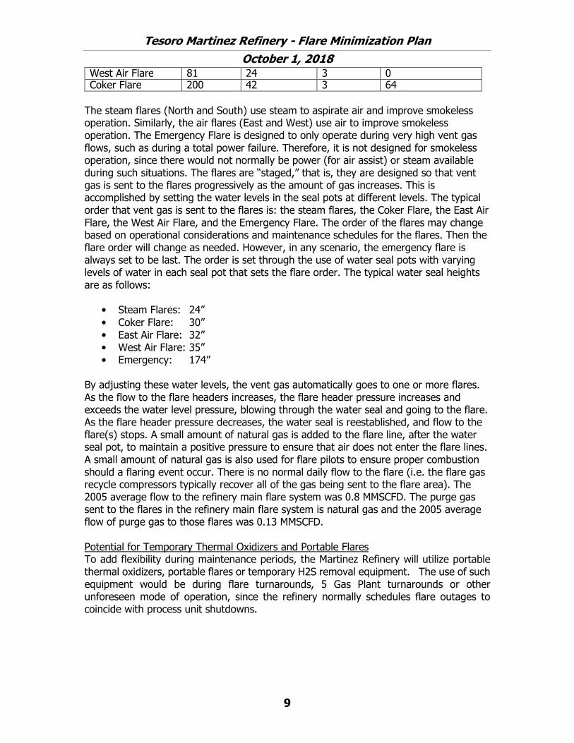
West Air Flare 81 24 3 0 Coker Flare 200 42 3 64
The steam flares (North and South) use steam to aspirate air and improve smokeless operation. Similarly, the air flares (East and West) use air to improve smokeless operation. The Emergency Flare is designed to only operate during very high vent gas flows, such as during a total power failure. Therefore, it is not designed for smokeless operation, since there would not normally be power (for air assist) or steam available during such situations. The flares are “staged,” that is, they are designed so that vent gas is sent to the flares progressively as the amount of gas increases. This is accomplished by setting the water levels in the seal pots at different levels. The typical order that vent gas is sent to the flares is: the steam flares, the Coker Flare, the East Air Flare, the West Air Flare, and the Emergency Flare. The order of the flares may change based on operational considerations and maintenance schedules for the flares. Then the flare order will change as needed. However, in any scenario, the emergency flare is always set to be last. The order is set through the use of water seal pots with varying levels of water in each seal pot that sets the flare order. The typical water seal heights are as follows:
• Steam Flares: 24”• Coker Flare: 30” • East Air Flare: 32”• West Air Flare: 35”• Emergency: 174”
By adjusting these water levels, the vent gas automatically goes to one or more flares. As the flow to the flare headers increases, the flare header pressure increases and exceeds the water level pressure, blowing through the water seal and going to the flare. As the flare header pressure decreases, the water seal is reestablished, and flow to the flare(s) stops. A small amount of natural gas is added to the flare line, after the water seal pot, to maintain a positive pressure to ensure that air does not enter the flare lines. A small amount of natural gas is also used for flare pilots to ensure proper combustion should a flaring event occur. There is no normal daily flow to the flare (i.e. the flare gas recycle compressors typically recover all of the gas being sent to the flare area). The 2005 average flow to the refinery main flare system was 0.8 MMSCFD. The purge gas sent to the flares in the refinery main flare system is natural gas and the 2005 average flow of purge gas to those flares was 0.13 MMSCFD.
Potential for Temporary Thermal Oxidizers and Portable Flares To add flexibility during maintenance periods, the Martinez Refinery will utilize portable thermal oxidizers, portable flares or temporary H2S removal equipment. The use of such equipment would be during flare turnarounds, 5 Gas Plant turnarounds or other unforeseen mode of operation, since the refinery normally schedules flare outages to coincide with process unit shutdowns.

Tesoro Martinez Refinery - Flare Minimization Plan
October 1, 2018
10
Flare Gas Recovery System At the flare area, incorporated into the flare system, is a flare gas recovery system. The system is comprised of a recycle compressor and a spare compressor (CP-539 and CP-540 rotate between being in operation and on cold standby as a spare) that draws flare gas from the flare headers and compresses the flare gas, sending it to the No. 5 Gas Plant (GP). At the No. 5 GP, the gas is further compressed and sent to an amine treating system for removal of sulfur compounds and is then sent to the fuel gas system. See Attachment 1 for additional details regarding the flare gas recovery, fuel gas, and wet gas systems.
Under normal refinery operating conditions, the flare gas recovery system recovers all of the vent gas. The flare gas recycle compressors have a nameplate capacity of 4.0 MMSCFD each and the maximum observed capacity is about 5.0 MMSCFD. The maximum design temperature for these compressors is 160° F on the compressor discharge. The compressor gas design molecular weight (MW) was based on three cases: a low MW case of 5.8, a typical MW case of 17.9, and a high MW case of 25.9. No maximum molecular weight was specified in the design.
The spare flare gas recovery compressor is in cold standby to reduce the risk of losing both compressors due to an adverse event. For example, if a slug of liquid entered the flare gas recovery compressor system and the existing systems failed to shut down the compressor, the compressor could be seriously damaged. If the spare compressor was set to automatically start, the spare compressor could also be seriously damaged which would result in all recovery compressor capability being lost for weeks or longer. However, by keeping the spare compressor in cold standby, if one compressor shuts down, procedures require that the operator determine the cause of the compressor shutdown and resolve that problem before attempting to start the spare recovery compressor. It typically takes about 15 minutes to start the spare compressor and another 10 minutes to bring the compressor to full rate. This reduces the risk that one event would take out both recovery compressors. Clearly, losing the recovery capacity for a few minutes is preferable to the risk of losing the recovery capacity for weeks or longer.
Recently, a number of regulatory considerations have directed Martinez to work toward operation of the second flare gas recovery compressor when the capacity of the first compressor has the potential to be exceeded. As a preventative measure, the refinery now starts up the second compressor in order to recover more gases. Operating the second compressor as well as controlling the depressuring sequence during shutdowns, has dropped the amount of flaring significantly.
However, as noted above, the risk of losing both flare gas recovery compressors increases. In addition to the situation described above, if the oxygen content of the flare gas exceeds 3%, both recovery compressors would be shut down, regardless of the operating mode, to ensure an explosive mixture does not occur in the compressors. Various other conditions can also result in the shutdown of both recovery compressors. Situations that would lead to the flare gas recycle compressor tripping off-line include but are not limited to:

Tesoro Martinez Refinery - Flare Minimization Plan
October 1, 2018
11
• A low level in the flare gas compressor discharge knockout pot as indicated by a
switch on the pot (LSLL-1124 and 1136) or by the transmitter on the pot (L-1125 and 1137) will trip the compressor. If the liquid level is too low, seal water circulation could be lost which would lead to damaging the compressor, the seal water pumps, or the seal water cooler.
• A high level in the flare gas compressor discharge knockout pot as indicated by
the transmitter on the pot will trip the compressor (L-1125 and 1137). If the liquid level is too high, liquid could back into the compressor suction which would lead to a failure of the compressor.
• A low pressure on the suction line to the compressors will cause the compressor
to trip. If a vacuum is pulled on the flare line, air could be drawn into the flare header causing the potential for an explosive mixture in process equipment. (PT-1120, PT-1130 and 1131)
• A low flow of seal water back to the compressor will trip the compressor. If the
liquid level is too low, seal water circulation could be lost which would lead to damaging the compressor, the seal water pumps, or the seal water cooler. (F-1121 and 1133)
• A high level on the compressor suction pot (V-107) will shut down the compressor.
Liquid carry over into the compressor would result in damage to the compressor. (L-1160)
• A high concentration of oxygen in the flare gas stream will cause the compressors
to shut down. High oxygen levels in the flare gas could result in an explosive mixture and increased fouling in process equipment. (19-ASHH1161, 1162, 1163)
• A high compressor discharge pressure will cause the compressor to trip. This is to
prevent damage to the compressor and associated equipment.
• A high pressure on the extraneous knockout pot at No. 5 GP will cause the compressor to trip. This is to prevent a recycle loop from occurring since the main accumulator at No. 5 GP will relieve to the flare system at 10 psig. (3-PSHH-4677/4675 1 of two voting)
• High bearing temperatures on the compressor (T-1145, 1146, 1147, and 1152) or
on the compressor motor (T-1171, 1172, 1173, and 1174) will cause the compressor to trip. Continued operation during imminent bearing failures could result in catastrophic failure of the compressor.
• An electrical failure on the compressor motor/starter circuitry will cause the
compressor to trip. Such an electrical problem could cause further damage to the motor or a result in a fire.

Tesoro Martinez Refinery - Flare Minimization Plan
October 1, 2018
12
• If any one of the stop buttons are pushed, the compressors will trip. There is onelocated in the Thermal Area control room, one located at No. 5 GP, and one locatedat the local panel for the compressor.
There is no formal written procedure describing when it is permissible to re-start a flare gas recycle compressor, however, in most cases, the operator would restart the compressor or start up the other flare gas recycle compressor after the reason for the compressor trip was understood and corrected. The reason for the compressor trip must be identified and corrected prior to restarting either compressor to ensure that any potential safety or equipment hazards are properly addressed. Should the determination be made that the cause of the compressor trip was a mechanical breakdown of that specific compressor (and no other safety or equipment hazard existed), the other flare recycle compressor would be started. When neither of the flare gas recycle compressors are operating, the gases in the flare system will go to the flares.
The manufacturer’s recommended frequency and schedule for the flare gas recycle compressor repair and maintenance is provided in Attachment 2. However, the maintenance recommendations contained in the Original Equipment Manufacturer (OEM) manual for the flare gas compressors are from a generic manual that the OEM supplies with all their products and so many of these recommendations are not completely consistent with the requirements of these specific compressors. The practices followed at Martinez are based on Industry Best Practices and are focused on improved equipment reliability. For example, Section 4-2 paragraph a., describes lubricated couplings which are not present on the flare gas recycle compressors at Martinez. The Martinez compressors utilize a disc-pack dry coupling. Additionally, Section 4-2, paragraph b & c, Section 4-3, and Section 4-4 describe frequency and procedure by which to lubricate various bearings and couplings. For the Martinez compressors, all bearings are fitted with automatic grease lubrication devices which inject a measured amount of grease at specific time intervals. This provides the best lubrication for the bearings. As a third example, Section 4-5 describes preventative maintenance procedures for stuff box packing within the compressor. The flare gas recycle compressors at Martinez do not have packing. Mechanical seals are required due to the potentially sour (sulfur containing) hydrocarbon gases contained in the process.
As part of the Predictive Maintenance program, Martinez monitors the vibration levels on these compressors monthly when they are in operation. In addition, the lubricators are checked monthly, as part of the vibration rounds, and semi-annually as part of the lubrication rounds. Martinez believes this maintenance regime is better suited to the flare gas recycle compressors.
The location of monitors that could trip off the flare gas recycle compressors are identified on the flare system process flow diagram (PFD). They are noted as a “T” near a circled item. The abbreviations used in circled items on the PFD are:
P Pressure T Temperature F Flow L Level

Tesoro Martinez Refinery - Flare Minimization Plan
October 1, 2018
13
A Analyzer (typically oxygen) RO Restriction Orifice
The current trip settings are also included on the PFD. For example, the compressor knockout pot trip temperature is 160° F, the compressor motor bearings temperature trip is 180° F, and the compressor case temperature trip is 220° F. (The recovered flare gas temperature typically ranges between 80 and 120° F, and based on current knowledge, there has not been a flare event associated with the loss of the flare gas recovery compressors due to a high temperature trip of those compressors.
The only flare gas compressor trips that are not included on the PFD are: 1) the stop switches for the compressors, as noted above,2) the high pressure on the extraneous knockout pot at No. 5 GP (which trips at 7
psig) and,3) the electrical failure monitor on the compressor motor/starter circuitry.
These have not been included on the PFD because the equipment is not located on this PFD (i.e. the No. 5 GP and compressor motors) and would unnecessarily clutter the PFD.
The flare gas recovery compressors do not have a nitrogen content trip and the flare gas recovery compressors can handle essentially any amount of nitrogen in the gas. However, the amount of nitrogen that can be handled in the fuel gas system (which is the ultimate disposition of this gas) is limited. There is no defined nitrogen content specification for the fuel gas. The compressors are shut down for high nitrogen concentration if they are adversely affecting the heat energy value of the fuel gas or the operation of the No. 5 GP wet gas compressors.
ARU Flare The Ammonia Recovery Unit (ARU) Flare is connected primarily to the ARU but also to the SCOT and DEA units. The majority of the flaring situations result from ARU operations. The ARU Flare is equipped with a MW analyzer which is used to provide the operators with an indication of the flare gas composition. The flare gas composition, depending on the value, can assist Operations in predicting whether a potential flaring event is likely. Corrective action can be taken to reduce and/or avoid the resulting flare events.
The ARU Flare is equipped with a relief scrubber upstream of the ARU Flare stack. The flare stack is also equipped with a knockout pot and water seal to remove entrained liquids, provide some additional scrubbing capacity and prevent backflow from the flare into the flare header.
The flare source number, capacity (per engineering relief calculations) and construction date are provided in the table below:
Flare Name Source Number
Capacity (MMBtu/day)
Construction Date
ARU Flare S-1013 64,080 1983

Tesoro Martinez Refinery - Flare Minimization Plan
October 1, 2018
14
Additional physical parameters for the flare including the flare height, pipe diameter, number of pilots and number of steam injection nozzles is provided in the table below:
Flare Name Height (ft.)
Pipe Diameter (in.)
No. of Pilots
No. of Steam Injection Nozzles
ARU Flare 160 84 (bottom) 45 (mid)
3 0
ARU Flare Relief Scrubber Gases from the relief header are fed to the scrubber where they are contacted with a continuously circulating stream of ammonia solution. This solution absorbs hydrogen sulfide (H2S) and ammonia with the resulting overhead vapor flowing to the flare. Circulation of the ammonia solution is maintained by a scrubber pump on a continual basis. Should a large relief load be present, a second larger circulation pump is started which increases scrubbing capacity by 2.7 times. The rich circulating solution is purged from the scrubber and sent to the feed mixing drum for reprocessing through the ARU. The scrubber itself is designed with two compartments. The first is used during normal operating conditions whereas the second is used during upset conditions when extra H2S and ammonia absorbing capacity is required.
ARU Flare Description The flare system is comprised of the knockout drum, the water seal, and flare stack. The overhead vapors from the relief scrubber are fed to the knockout drum. This drum removes any entrained liquids and sends them to the feed mixing drum for reprocessing. The vapors from the knockout drum then feed the flare seal pot which contains a water seal to prevent backflow from the flare into the scrubbing section. The liquid in the water seal is flushed on an as needed basis and make up water is provided by cold condensate from the ARU. The vapor leaving the seal pot then passes through a molecular seal which effectively prevents any air from entering the flare stack below the seal for extended periods of time. The seal is flushed with hot condensate to clean the seal pockets.
The flare tip employs natural gas fired continuously operated pilots. Pilots can be relit remotely in the control room or at a local panel if low temperature is detected. A backup system can also be used. The manually operated flare front generator uses instrument air mixed with natural gas that flows to the pilots to re-ignite them.
50 Unit Flare The 50 Unit Flare system is comprised of a new collection header, flare gas recovery system knockout drum, a new liquid ring flare gas recovery compressor, and a flare. In addition, the existing 50 Unit wet gas compressors are also connected into the flare gas recovery system for periods of larger flow and as a backup for the new flare gas recovery compressor. The recovered gas is routed to the refinery fuel gas system at the No. 5 GP. Any recovered liquid in the knockout drum is cooled and pumped to the refinery recovered oil system.
The flare source number, capacity (per engineering relief calculations) and construction date are provided in the table below:

Tesoro Martinez Refinery - Flare Minimization Plan
October 1, 2018
15
Flare Name Source Number
Capacity (MMBtu/day)
Construction Date
50 Unit Flare S-1524 672,000 2010
Additional physical parameters for the flare including the flare height, pipe diameter, number of pilots and number of steam injection nozzles is provided in the table below:
Flare Name Height (ft.)
Pipe Diameter (in.)
No. of Pilots
No. of Steam Injection Nozzles
50 Unit Flare 310 30 3 42
The steam flares use steam to aspirate air and improves smokeless operation. The typical water seal height is 61”.
3.1.2 Process Flow Diagrams A PFD of the Main Flare System and associated vessel diagrams are provided in Attachment 3.
The PFDs of the 50 Unit Flare system and associated seal pot diagram are provided in Attachment 3A.
The PFDs of the ARU Flare system and associated seal pot diagram are provided in Attachment 4.
3.1.3 Description of Monitoring and Control Equipment A description of the monitoring for the Main Flare System, the 50 Unit Flare System and the ARU Flare is provided below. The control for these flares is included in the flare system information in section 3.1.1 above.
Main Flare System Monitoring
Flare Flow Monitoring The 42”, 48”, and 24” flare header flows are monitored by an ultrasonic flow meter located in each of the flare headers. Ultrasonic flow monitors are also installed in the outlet of the flare gas recovery compressors, the line to the Coker Flare, and on the flare line to the steam flares. This data is provided in monthly reports to the District.
Currently, the amount of vent gas being flared is determined by adding all the flare header flows (i.e. the 24”, 42” and two 48” headers) and subtracting the recovered vent gas flows from the flare gas recycle compressors (also known as the flare gas recovery compressors). During low flows of vent gas to the flares, the Steam Flare flow meter is used, since the Steam Flares are the first flares to see flare gas. Martinez believes that this provides the best accuracy at the lower flare flow levels.
During these low flare flow situations (where the gas is only being sent to the steam flares), Martinez uses the steam flare flow meter to determine the amount of gas being flared. The output from this meter is compared to seal pot monitoring (i.e. seal pot water level vs. flare header pressure) to determine the flow. When the seal pot water level (expressed in inches of water column) exceeds the flare gas pressure at the seal

Tesoro Martinez Refinery - Flare Minimization Plan
October 1, 2018
16
pot (also expressed in inches of water column), this indicates that there is insufficient pressure in the flare header to go through the water seal, and there is no flow to the flare. In this case, there is zero flow for the flare. By January 2019, to comply with the Consent Decree and Refinery Sector Rule, individual flare gas flow meters will be installed after the seal drums at the East Air Flare, West Air Flare, and Emergency Flare. To address flows to the flare header system, Martinez employs various monitors to determine the source of flare gas to the system. Several flow meters are used to identify the process area or unit that is generating flare gas to assist in determining and reducing flow from that source. In addition, other operating parameters are monitored (e.g. pressure, valve position, etc.) to identify the source of flare gas. By routinely monitoring these parameters, proactive actions can be taken to identify the cause of the additional vent gas and, to the extent possible, take appropriate action. This has proven to be an effective method to minimize flare gas flows. Flare Gas Composition Monitoring As part of Martinez’s plan to comply with NSPS Ja requirements, the flare gas composition monitoring scheme for the refinery was revised. Each flare in the main flare system and 50 Unit flare has an H2S analyzer to monitor the concentration in the vent gas. The total sulfur content of the flare gas is analyzed by a continuous total sulfur monitor in the north and south steam flare line, since these are the flares that are normally first in the refinery staged flare system. When the Coker Flare is staged first, the Coker Flare H2S analyzer is used. For the Consent Decree, Martinez purchased gas chromatographs (GC) to measure the hydrocarbon content of the vent gas. Martinez certified these analyzers in 2017. We perform manual sampling when the GC’s are not functioning. The hydrocarbon data is provided in monthly reports to the District. Video Monitoring In addition, cameras are used to obtain a visual record of each of the flares once per minute. These are archived as digital picture files (jpg format) and provided to the District monthly on DVDs. Martinez has increased the number of flare pictures to meet the Consent Decree requirements of four pictures per minute. Flare Seal Pot Level Monitoring The water level in each of the flare seal pots is continuously monitored, along with the flare header pressure, near each seal pot. This data can be used to determine whether the water seals are intact as a way of determining whether any flaring is taking place. Other Flare Monitoring The flare pilots are also monitored via thermocouples to ensure that the pilot lights remain lit. In addition, the amount of pilot gas and purge gas is monitored and reported to the District in the flare monthly reports.

Tesoro Martinez Refinery - Flare Minimization Plan
October 1, 2018
17
ARU Flare System Monitoring Flare Flow Monitoring The ARU Flare flow is monitored by a continuous ultrasonic flow meter. This data is provided in monthly reports to the District. Flare Gas Composition Monitoring Due to the potentially high ammonia and H2S content of the flare gas, representative, worst case compositions are used to determine emissions, pursuant to Regulation 12-11-502.3.1a. Video Monitoring A camera records a visual record of the ARU Flare once per minute. These are archived as digital picture files (jpg format) and provided to the District monthly on DVDs. Flare Seal Pot Level Monitoring The water level in the ARU Flare seal pot is continuously monitored, along with the flare pressure. This data can be used to determine whether the water seal is intact as a method of determining whether any flaring is taking place. Other Flare Monitoring The flare pilots are also monitored via thermocouples to ensure that the pilot flames remain lit. In addition, the amount of pilot gas and purge gas is monitored and reported to the District in the flare monthly reports. 50 Unit Flare System Monitoring Flare Flow Monitoring The 50 Unit Flare flow is monitored by a continuous ultrasonic flow meter. This data is provided in monthly reports to the District. Flare Gas Composition Monitoring The sulfur content of the 50 Unit Flare header is monitored by a continuous monitor for H2S. The hydrocarbon content of the flare header is taken manually during a flare event and analyzed in Martinez’s lab using a gas chromatograph to determine the hydrocarbon composition of the flare gas. This data is provided in monthly reports to the District. Video Monitoring A camera records a visual record of the 50 Unit Flare once per minute. These are archived as digital picture files (jpg format) and provided to the District monthly on DVDs. Flare Seal Pot Level Monitoring The water level in the 50 Unit Flare seal pot is continuously monitored, along with the flare pressure. This data can be used to determine whether the water seal is intact as a method of determining whether any flaring is taking place.

Tesoro Martinez Refinery - Flare Minimization Plan
October 1, 2018
18
Other Flare Monitoring The flare pilots are also monitored via thermocouples to ensure that the pilot flames remain lit. In addition, the amount of pilot gas and purge gas are monitored and reported to the District in the flare monthly reports.
The locations of flow meters, temperature and pressure indicators are shown on the PFDs included in Section 3.1.2 above. The locations of sample points and continuous emission monitoring (CEM) equipment are also shown on the PFDs included in Section 3.1.2.
3.2 Reductions Previously Realized
Over the last decade, Tesoro has significantly reduced flaring. This has been accomplished predominantly by starting up the second flare gas recovery compressor on the main refinery flare gas system, and through improved awareness and management of the flare system to minimize flaring. From July 2002 to present, non-methane hydrocarbon flaring emissions have been reduced from about 2 tons per day to about 3 lb/day on average (based on 2018 data). This represents a reduction of more than 99%. In 2016 Martinez further increased its efforts in decreasing flaring. During planned events, Operations and Planning have staggered shutdowns to stay within the capacity of the two compressors. During unplanned shutdowns, Operations has increased their efforts to startup the second compressor and make adjustments to decrease streams to the flare. These efforts have greatly reduced the number of flaring events in 2016 and 2018.
Martinez has reduced flare flows due the following:
• Planned use of the Flare header will be coordinated to prevent exceeding the
capacities of the flare gas recovery compressors to the maximum degree
practicable.
• All discretionary venting to the flare header due to planned maintenance will
be coordinated with the Shift Superintendent. Operations staff filling this role
manage such venting to stay within the Compressor capacity to the extent
feasible.
• Planned venting activities which are anticipated to exceed the capabilities of
the primary compressor will include proactively activating the second
Compressor to prevent flaring.
• Base load to the flare gas recovery compressors are monitored. If there is an
increase in the amount of waste gas recovered on a daily basis, the refinery
has a procedure to find the source and eliminate the flow. This proactive
monitoring allows for additional recovery capacity to offset flaring during
actual flare events due to emergencies or unforeseen circumstances.
Other actions that have been taken to reduce flaring include improved planning efforts related to maintenance turnarounds and operational changes to keep the fuel system in balance. Prior to maintenance turnarounds, Tesoro has evaluated the potential flaring

Tesoro Martinez Refinery - Flare Minimization Plan
October 1, 2018
19
that could occur as a result of the turnaround and developed plans to try to eliminate or reduce flaring (see Section 3.3, Description of Planned Prevention Measures for more information on this process). Such plans consider whether vent gases generated during shutdown and maintenance can be routed to other closed systems first to minimize material sent to the flare system, and for those vent gases that must still be sent to the flare, whether venting to the flare more slowly would help to stay within the flare recovery system capacity.
The plans also consider the timing of the various unit shutdowns and purging opportunities to keep the rate to the flare gas system within the recovery capability. For example, during the last planned major maintenance activity, units were prioritized relative to when they could depressure to the flare system. The flare gas recovery compressor flow was monitored to stay within the system capacity, and additional vessel purging and depressuring was conducted as system capacity was available. It should be noted, however, that situations can occur when the volume of nitrogen required to properly clear the vessel (and catalyst) of hydrocarbon material for safe entry is such that it can exceed the flare recovery system capacity. In addition, such plans have considered the use of chemicals to improve initial hydrocarbon removal to reduce the time needed for steam out or purging to flare.
In addition, various actions have been taken as a result of causal analyses performed for flaring events. These actions are included in Attachment 5.
Operations also manages the fuel gas and hydrogen systems to keep the system in balance. Actions are taken to modify unit operations at fuel gas and hydrogen generating units to reduce gas make, if needed (such as changing unit rates and reducing FCCU temperature). In addition, actions are taken to try to increase hydrogen uptake and increase firing at furnaces to consume more of these commodities to keep the fuel gas and hydrogen systems in balance. Typically, the fuel gas system is kept in balance but there are situations when this is not the case. For short periods of time, upsets, malfunctions, emergencies, and other situations can result in the fuel gas system becoming imbalanced until the situation can be stabilized and unit operations can be adjusted to come back into balance. So, efforts to prevent fuel gas imbalance situations apply to all units at the facility whose operation may result in flaring associated with a fuel gas imbalance.
There can be longer-term situations where the fuel gas system is out of balance. For example, there can be situations where the fuel gas producing units are at minimum rate and the fuel gas system is still out of balance. Any further rate reductions would result in the units becoming unstable and pose a safety concern. Actions are taken to minimize the length of time that such situations occur. These situations are infrequent and are generally associated with equipment maintenance/turnaround. Therefore, the duration of maintenance activities is minimized (e.g. overtime authorized), consistent with the work scope and good safety and environmental practices.
Additional information on fuel gas system imbalances is provided in the Startup and Shutdown Process portion of Section 3.4.1, the existing Martinez vent gas recovery,

Tesoro Martinez Refinery - Flare Minimization Plan
October 1, 2018
20
storage, & scrubbing capacities portion of Section 3.4.2, and the description of the wet gas, fuel gas, and flare gas recovery systems provided in Attachment 1.
Beyond this, the Operations shift organization works to maintain good communication and coordination so that the flare gas compressor load is not exceeded. Actions have also been taken to minimize acid gas flaring through monitoring and alarming the molecular weight of the vent gas and taking appropriate action based on that information. An increase in the molecular weight can be an indication that there is an increase in H2S in the relief header. By monitoring the molecular weight, the operators can be notified of a potential increase in H2S to the relief header and make operating moves to address the situation more quickly (e.g. reducing H2S stripping in the stripping column by reducing the stripping steam, which will reduce H2S to the relief header), resulting in the prevention of or a reduction in acid gas flaring.
3.3 Planned Reductions
A table summarizing the actions currently planned to effect further reductions in refinery flaring is provided in Attachment 6. These items have been identified through flaring evaluations as potential ways to either directly reduce flaring or reduce the chance of a flaring event. The Alky Gas Turbine Replacement project, which replaced the gas turbine with an electric motor, reduced the baseline load to the flare gas recovery compressors due to an improved spillback control system and increased reliability.
Martinez is also working on prevention measures to decrease flaring during the 5 Gas Plant Turnaround and to decrease the normal load to the flare gas recovery compressors.
A project identification number has been provided to allow the District to track these projects. The Approval for Expenditure (AFE) number or Project Tracking System (PTS) number has been provided. This is a unique number that is used for accounting purposes and follows the project. In addition, the estimated date of completion of the project has been provided.
Acoustic monitoring on hydrocarbon pressure relief valves are required for the Consent Decree. As leaking components are found, they are added to the turnaround lists for repair. This helps reduce base flow to the flare gas recovery compressors.
As part of the flare causal analysis process, incident teams identified methods that may help to prevent a recurrence of the incident. Many of these items are not key actions to prevent flaring, but are actions that may have a potential (even slight) to prevent the incident. To be conservative, these items are identified because of a lack of information to rule them out as a potential contributing cause to flaring. For example, on the 2/17/2011 flaring incident, flaring was initiated as a result of an emergency shutdown of No. 1 Hydrogen plant, and the depressuring of both stages of the Hydrocracker due to loss of hydrogen from the No.1 Hydrogen plant emergency shutdown. The investigation for this event highlighted several contributing factors, and many of the corrective actions identified in this investigation are related to changes in control strategies, instrumentation, operating procedures, etc. which individually would not eliminate flaring but would potentially reduce the risk of a recurrence. This example illustrates that

Tesoro Martinez Refinery - Flare Minimization Plan
October 1, 2018
21
many of these actions may not directly cause flaring, however, Martinez is committed to studying each action to determine whether implementing them will result in the potential to minimize flaring. In addition, various potential actions were identified as a part of flare causal analyses. These potential actions are under consideration and are, therefore, not truly “planned reductions” yet. These open action items may yet develop into flare reduction projects but not enough work has been completed yet for them to reach the point of being a planned reduction. These open action items really do not fit in either “reductions previously realized” or “planned reductions” sections. However, Martinez has provided information to allow the District to track these open action items and will include them in the planned reductions section in future FMP updates if they progress to that status. These items are provided in Attachment 7.
3.4 Prevention Measures
The following section discusses flaring prevention measures and practices utilized at Martinez. 3.4.1 Maintenance Activities Including Startups and Shutdowns This section discusses refinery maintenance and turnaround activities and outlines measures to minimize flaring during both preplanned and unplanned maintenance activities. Maintenance Activities Maintenance activities can result in a higher than normal flow of material to the flare gas recovery system. In order to maintain process equipment, the first step is to clear the process equipment and associated piping of hydrocarbons before the system is opened to the atmosphere, for both safety and environmental reasons, in compliance with BAAQMD Regulation 8 Rule 10, (Process Vessel Depressurization). How this is accomplished depends on the physical properties of the hydrocarbons to be removed (vapor pressure, viscosity) and on the process details of the equipment that is to be maintained. The first step is to recover as much of the hydrocarbon as is possible to another point in the processing prior to opening the equipment to the flare or the atmosphere. For example, liquid hydrocarbons can be pumped to tankage or another process system and gases under pressure may be depressurized to another process unit. Heavy hydrocarbons that are viscous at ambient temperatures are often displaced from the equipment to be maintained using lighter hydrocarbons, e.g. light cycle oil (LCO). The LCO can then be pumped from the equipment. Although depressurization and pump-out can normally be used to remove the bulk of the hydrocarbon from the equipment, some residual material can remain. Following pump-out or depressurization to other process equipment, the next step in decommissioning involves sending the residual gas to a fairly low-pressure system that has the ability to accept a wide range of hydrocarbon materials, the refinery wet gas system, where available. This system recovers various gas streams in the refinery.

Tesoro Martinez Refinery - Flare Minimization Plan
October 1, 2018
22
Lastly, any remaining hydrocarbon is sent to the lowest-pressure recovery system, the flare gas recovery system, so the hydrocarbon can be recovered as fuel gas. This remaining gaseous hydrocarbon can be purged to the flare using an inert gas such as nitrogen. Alternatively, nitrogen can be added to the equipment, increasing the internal pressure. The resulting mixture of nitrogen and hydrocarbon can then be released to the flare header. Steam can be substituted for nitrogen when heat, moisture, vessel temperature, and pressure do not constrain its use. For example, steam cannot be used to purge vessels in caustic service due to the potential for stress corrosion cracking. Steam also cannot be used for most reactors since it would damage the catalyst in the vessel. In addition, some vessels are coated internally for corrosion resistance and steaming cannot be used because it would result in a failure of the coating due to the heat. Substituting nitrogen with steam can produce some small reduction in flaring since the steam condenses in the flare line and is decanted into the refinery slops system, whereas the entire volume of nitrogen goes to the flare. For any small amount of liquids remaining in equipment, steam or nitrogen are routinely used to push the liquid to the flare system knockout vessel(s). The liquid hydrocarbon and condensed steam are separated from the vapor phase and returned to the refinery’s recovered oil system and to wastewater treatment either at the unit knockout drum or at the flare knockout drum. Nitrogen with hydrocarbon vapor continues on to flare gas recovery. Once the liquid hydrocarbon has been displaced, the flow of steam or nitrogen is continued to remove any residual hydrocarbon clinging to the equipment walls. Steam can be more effective for heavier materials as it increases their volatility by increasing temperature. Generally, hydrocarbon can be effectively removed from vessels through pumping out the hydrocarbon and purging the vessel with nitrogen or steam. However, when this process is not adequate to clean the vessel for opening, proprietary solutions can be used to chemically clean the vessel. Also, these solutions typically contain materials that are somewhat more hazardous with respect to personnel exposure that nitrogen and steam. Therefore, when nitrogen and steam are effective, those methods are preferentially used. When used, proprietary solutions are circulated, so that venting is not required. (Nitrogen and steam are once-through purging agents; when purging with nitrogen or steam, the systems being purged must be vented to a flare to prevent pressure from building.) The circulating solution is often filtered to remove contaminants, and fresh chemicals are added as required to maintain solution properties. When the system is clean, the solution is drained, and the equipment is typically flushed with water. Examples of equipment that might be cleaned using proprietary solutions include pressure vessels, distillation columns, furnaces, and heat exchangers. System components often vary depending on maintenance needs. Although these procedures eliminate hydrocarbon emissions to the atmosphere related to equipment opening, they require significant volumes of steam or nitrogen in order to be effective. This high flow rate of purge gas can create situations where flare gas

Tesoro Martinez Refinery - Flare Minimization Plan
October 1, 2018
23
recovery is not feasible. These situations relate either to a change in flare vent gas composition (change in molecular weight, heat content, or temperature) or to the increase in vent gas flow rate. Changes in the composition or temperature can be such that the compressors used to recover the vent gas are unable to properly compress the gas. Increases in vent gas flow rate can be such that the compressors cannot recover all the gas.
In addition, there are many process and reactor systems within the refinery that contain gases with a high hydrogen content. When this equipment is decommissioned by depressurization to the flare gas header, there can be a sharp decrease in the flare gas average molecular weight. This can also result in situations where flare gas recovery is not feasible due to composition or vent gas flow issues (i.e. the amount of flow may exceed the recovery capacity of the recovery system).
Effect of Recovered Flare Gas on Downstream Equipment Gas composition can impact the operation of flare gas recovery equipment as well as equipment utilizing the recovered gas. Specifically:
• High nitrogen or hydrogen content can impact heaters, boilers, flare gas recoverycompressors, and fuel gas compressors.
• Steam impacts knockout drums and compressors, while increasing sour waterproduction.
High hydrogen concentration reduces the Btu value of the fuel gas. If the Btu content drops low enough, this can result in unstable furnace operation and can reduce unit production rates. At the steam boilers, this can result in a significant reduction in steam production and cause an upset in the steam system, which can upset unit operations.
The flare gas compressors are not significantly impacted by higher hydrogen levels, since they are positive displacement compressors. However, high hydrogen concentrations in the gas feeding the centrifugal wet gas compressors (flare gas is recovered and sent to these compressors) affects the performance of the wet gas compressors in that it will drive the compressor closer to its surge curve which can be potentially damaging to the machine.
High flows of nitrogen from equipment decommissioning can lead to a much higher than normal inert content in the mixed flare gas, greatly reducing its heat content (measured as Btu/scf). When this low Btu flare gas is transferred to the fuel gas header, the lower heat content can have the effect of reducing combustion efficiency, as the burners are designed to operate with fuels that have a higher heat content per cubic foot. In extreme cases, the heating value of the gas can be reduced by dilution with nitrogen to the point of extinguishing the burner flame. This creates the potential for unburned fuel to accumulate in the heater or boiler, leading to an explosion when it is re-ignited. NFPA 85 – Boiler and Combustion Systems Hazards Code and NFPA 86 Standards for Ovens and Furnaces warn against the use of practices that can lead to this possibility.
The higher than normal nitrogen content of flare gas that can result from nitrogen purging has the effect of greatly increasing its molecular weight. Reciprocating
Tesoro Martinez Refinery - Flare Minimization Plan
October 1, 2018
24
compressors increase the pressure of a constant inlet volumetric flow rate of gas. For a given volume of gas, an increase in molecular weight creates an increase in its mass. This increases the work that the compressor has to do to compress the gas, overloading and potentially damaging the machine. A major advantage of using steam to clear hydrocarbons from equipment is its elevated temperature, however this can be a disadvantage with respect to flare gas recovery. When the distance the gas must travel to reach the flare gas compressor is large, the gas will cool, and much of the steam will condense and be removed as water at the knockout drum. However; with a shorter flare line or a long-duration steam out event, the temperature of the flare gas at the flare gas compressor can be elevated significantly. If the temperature of the flare gas stream at the inlet to the flare gas compressor exceeds machine limits, the gas must be diverted away from the compressor inlet in order to avoid mechanical damage. Another disadvantage of the use of steam is that most of what is added as a vapor will condense in the flare gas headers and be removed via the water boot of a knockout drum, either as the result of cooling as it flows through a long flare line or in a chiller/condenser included specifically for removal of water vapor from the flare gas. This creates a sour water stream requiring treatment. Shutdown and Startup Process During periods of startup and shutdown, a potential for flaring exists. This can be due to several reasons including an imbalance of material producers and users (e.g. fuel gas or hydrogen). Flaring can also occur due to specific startup or shutdown procedures that require venting to the flare system during some portion of the startup or shutdown process. Tesoro makes every effort to eliminate flaring from startups and shutdowns. There are, however, situations where this goal is not achieved. Martinez is a highly complex refinery and has a high degree of unit integration. Therefore, the shutdown and start-up of a process unit often affects one or more units upstream or downstream, and in some cases the entire refinery. As a processing unit is shut down, rate is typically reduced to minimum, and the operations of other affected units are adjusted accordingly in a controlled fashion. Typically, minimum rate is about one-half of a unit’s design capacity, and is determined by equipment constraints. When the unit ultimately does shut down, meaning feed to the unit is reduced from minimum to zero, imbalances may occur at other units that are upstream or downstream, or in the refinery as a whole. Flaring can often be prevented, but in some cases the operations of the units that are affected cannot be adjusted quickly enough (due to mechanical and process limitations), and excess material must be flared to avoid over-pressuring equipment. During unit start-ups, similar situations can occur. For example, when a catalytic reforming unit is started up, hydrogen is initially produced more quickly than can be consumed in the refinery, and the excess hydrogen must be flared until operations can be balanced. Similarly, when a catalytic reforming unit is shut down, some amount of excess hydrogen must be produced at other hydrogen-producing units in advance to compensate for the loss that is about to occur. Once the unit has been shut down, operations can be balanced, and flaring stops. In some situations, part

Tesoro Martinez Refinery - Flare Minimization Plan
October 1, 2018
25
of the excess hydrogen required in start-up and shutdown situations can be routed to the refinery fuel gas system up to the operating limits of that system.
At the Chemical Plant, start-up and shutdown procedures involve sending gas to the flare via the relief scrubber. This is done to ensure personnel safety prior to maintenance activities and to protect equipment prior to re-commissioning. On shutdown, equipment is purged with steam to the relief system to ensure a safe environment for personnel entry during maintenance and inspection tasks. On start-up, air is purged from the unit using steam or nitrogen. The difficulties associated with recovery of Chemical Plant flare gas is discussed in the Existing Systems for Vent Gas Recovery portion of Section 3.4.2.
Analysis of Prior 5 years of Major Maintenance Related Flaring A review of the last 5 years of maintenance related flare events was conducted. Due to the time that has passed for many of those events, it was difficult to gather enough specific details of the situation (e.g. when purging started and stopped, vessels were opened, etc.) to develop specific findings. However, a review of the data confirms that vessel depressurization and purging, fuel gas system imbalances, and hydrogen system imbalances account for the majority of the flaring related to major maintenance activities. Provided below is an analysis of the major maintenance related flaring and the FMP planned prevention measure associated with each cause.
Historic Analysis of Prior 5 years of Major Maintenance Related Flaring A review of the last 5 years of maintenance related flare events was conducted. Due to the time that has passed for many of those events, it was difficult to gather enough specific details of the situation (e.g. when purging started and stopped, vessels were opened, etc.) to develop specific findings. However, a review of the data confirms that vessel depressurization and purging, fuel gas system imbalances, and hydrogen system imbalances account for the majority of the flaring related to major maintenance activities. Provided below is an analysis of the major maintenance related flaring and the FMP planned prevention measure associated with each cause.
Historic Major Maintenance Flaring Analysis Flaring events related to major maintenance were reviewed and the primary cause of the flaring for those events was grouped into 5 main categories. Those categories are: 1) hydrogen system imbalance, 2) flare compressor shutdowns, 3) fuel gas systemimbalance, 4) shut down of the No. 5 Gas Plant, and 5) general flaring related to unit shutdowns. Each of these causes are discussed below, along with the method proposed in the FMP to address those situations.
Hydrogen System Imbalance This cause contributed to about 4% of the major maintenance related flaring incidents between 2013 and 2018 which were reviewed.
Primary Cause of the Flaring An imbalance in the hydrogen system can occur when the production of hydrogen is out of balance with hydrogen consumption at various units. This can occur during startup and shutdown situations at hydrogen producing or consumption units. Typically, when a

Tesoro Martinez Refinery - Flare Minimization Plan
October 1, 2018
26
hydrogen consumption unit is shutdown, the production of hydrogen can be reduced concurrently to ensure that the hydrogen system stays in balance. However, during a startup of a hydrogen producing unit, the hydrogen producing unit is brought on line and the hydrogen is sent initially to the flare header, so the hydrogen consumption units are not impacted by the startup. Those impacts can be related to low hydrogen purity during startup or the stability of unit operations due to varying hydrogen quantities. This results in several hours of flaring until the hydrogen product meets the quality specifications.
For example, Air Products operates a 35 MMSCFD Hydrogen Plant that is located inside the Martinez fenceline. Air Products normally produces utility hydrogen, which is sold exclusively to the Martinez. During start-up, feed is introduced into the unit and the unit begins producing a low purity hydrogen product. This product contains 75% hydrogen, 16% CO2, 3% CO, 6% methane and other impurities. This low purity hydrogen product cannot be used in Martinez as it contains contaminants that could permanently poison catalyst in other refinery catalytic process units (e.g. No. 3 HDS, Hydrocracker, etc.). As a result, the hydrogen is directed to a flare until the product hydrogen purity of 99% is achieved.
After the initial step of introducing feed, the Pressure Swing Absorber (PSA) skid is then placed in service to increase hydrogen purity and remove contaminants. It takes approximately 4 to 6 hours to line out the filtration system. Once the hydrogen reaches an acceptable purity, Air Products personnel notify the Martinez ‘s shift organization and the hydrogen is gradually introduced into the 400 lb hydrogen header. These types of units produce both CO and CO2 as by-products. Since both of these carbon oxides can inhibit hydrodesulfurization reactions, hydrogen produced at either No. 1 or No. 2 Hydrogen Plant is not suitable for use as make-up for hydrogen-consuming units until the level of CO plus CO2 is less than 50 ppm. This specification is confirmed by an on-line analyzer at No. 2 Hydrogen Plant. At No. 1 Hydrogen Plant this specification is confirmed by laboratory analysis and can be inferred by methanator differential temperature.
In 2017 Tesoro worked with Air Products to modify their startup procedures such that the last two Air Products startups did not exceed 500,000 SCF of flaring.
Hydrogen produced at catalytic reformers like No. 2 and No. 3 Reformers does not contain CO or CO2, and can normally be routed to the refinery soon after the introduction of feed, provided it is free of inert gases like nitrogen that may have been used to purge equipment.
Minimum rate at No. 2 Hydrogen Plant is about 18 MMSCFD, so that is typically the amount of hydrogen that must be flared until the level of CO plus CO2 is less than 50 ppm. At No. 1 Hydrogen Plant, minimum rate is approximately 35 MMSCFD, and once again, that is the amount of gas that must be flared until the hydrogen is on-spec.
During start-ups, the volume of off-spec hydrogen produced is too great to be handled by the refinery fuel gas system. Routing all of the off-spec hydrogen that is produced during start-up of either No. 1 or No. 2 Hydrogen Plant to the fuel gas system could

Tesoro Martinez Refinery - Flare Minimization Plan
October 1, 2018
27
potentially cause that system to become unstable and over pressure. Additionally some of the by-products produced during hydrogen plant start-ups, like CO and CO2, are not suitable fuel gas components. The number of hydrogen plant start-ups per year varies, but averages about two to three times per year. Efforts to reduce unplanned shutdowns to a minimum are ongoing. They include the maintenance and inspection programs mentioned in Section 3.4.3. In addition, attempts are in progress to extend the boiler inspection interval (state mandated) to reduce plant shutdowns. Further, the contract with Air Products includes provisions for on-stream efficiency. No. 1 and No. 2 Hydrogen Plants are shut down to inspect equipment, service relief valves, change catalyst, and re-new boiler operating permits. Also, hydrogen plant shutdowns can occur due to unit upsets and/or equipment malfunction. In addition, the No. 1 Hydrogen Plant may also be shut down to balance the refinery hydrogen system if a major hydrogen consumer like the Hydrocracker were to be shut down. Hydrogen Plant planned turnaround dates are driven by the need to inspect equipment, service relief valves, change catalyst, and re-new boiler operating permits, and cannot be extended beyond the required frequencies for these activities. MARTINEZ has not identified a way to introduce low quality hydrogen (i.e. high levels of CO and CO2) into the hydrogen header due to the adverse impact on the catalyst in downstream units. Attempts are made to bring the No.1 and No. 2 Hydrogen Plants up to full quality as quickly as possible (by bringing the methanator at No.1 Hydrogen Plant and the PSA unit at No.2 Hydrogen Plant on quickly) to minimize flaring. At Martinez, hydrogen is distributed from the hydrogen-producing units to the hydrogen-consuming units via a system of pipes that operates at about 400 psig. To avoid flaring, feed rates and other operating parameters at these hydrogen producing and consuming units are adjusted on a regular basis to maintain a balance. The start-up of a major hydrogen-producing unit like No. 1 Hydrogen Plant is typically planned and executed so that it coincides with the start-up of a hydrogen-consuming unit like the Hydrocracker. This practice reduces flaring by maintaining the balance between production and consumption. During unplanned situations, the startup and shutdown of hydrogen producing and consuming units may not coincide. During the shutdown and start-up of the No. 1 Hydrogen Plant, a portion of the hydrogen produced is recycled back into the hydrogen plant to avoid flaring. The hydrogen plant shutdown procedure has been revised, and this new technique was used successfully when the unit was shut down recently. Actions to Minimize or Eliminate Flaring during this Situation The following actions have been identified to minimize flaring associated with the startup of hydrogen production units:

Tesoro Martinez Refinery - Flare Minimization Plan
October 1, 2018
28
• Try to minimize the number of required plant start-ups each year, achieving ahigh plant on-stream efficiency and extending turnaround dates. This action isalready in place.
• Coordinate the start-up of hydrogen production units to insure product is used,when available, to minimize flaring. This action is already in place.
FMP Planned Prevention Measure The concept Martinez used to develop the FMP was to design a process to ensure that flare elimination or minimization was incorporated into work processes performed at the refinery (e.g. major maintenance activities, process unit turnarounds, etc.). This includes pre-turnaround planning, maintenance planning, and actions to eliminate or reduce the chance of malfunctions, upset, and situations associated with flare gas quality and quantity issues. This approach has been proven to eliminate or minimize flaring and will be utilized to identify and implement prevention measures. Martinez did not consider any other items not specifically noted in the FMP.
Flare Compressor Shutdowns This cause contributed to about 1% of the major maintenance related flaring incidents that were reviewed between 2013 and 2018.
Primary Cause of the Flaring The flare recycle compressors can shut down for various reasons. This can occur due to high oxygen content in the flare gas or for planned maintenance on the compressors. The flare compressors can also be purposely shut down when the flare gas quality is such that it could result in damage to the compressors or could cause gas quality problems in the fuel gas system. The compressors may also be shut down when there is more fuel gas available than there are fuel gas consumers, so recycling the flare gas to fuel gas system is not feasible.
If the oxygen content of the flare gas gets too high, the flare gas recovery compressors will automatically shut down to prevent the development of an explosive mixture in the system. Also, the flare recovery compressors and associated equipment may need to be shut down to perform maintenance. In addition, there are situations when the flare gas quality is such that the molecular weight of the flare gas could be low enough to damage compressors in the system that cannot handle lower molecular weight gases or the composition of the flare gas is such that it could impact the fuel gas quality and result in upsets at the furnaces burning the fuel gas. The fuel gas compressors could also be shut down if the fuel gas balance is such that there is excess fuel gas and recycling the flare gas would simply overpressure the fuel gas system and send the gas right back to the flare. This last situation is discussed further in a later portion of this section.
In each of these situations, the flare recycle compressors are no longer available to recover flare gas, and that gas is sent to the flares.
The oxygen in the flare gas primarily comes from the vapor recovery system which consists of atmospheric tanks and the marine vapor recovery system. Also, some minor amounts of oxygen can enter the system from the Merox Treating Unit. In the event of

Tesoro Martinez Refinery - Flare Minimization Plan
October 1, 2018
29
a high oxygen level in the flare gas, enrichment gas (propane) would typically be added to reduce the oxygen concentration. For example, if a tank PV valve is not operating properly, air can enter the system. If there is an unintended opening in the marine loading system (e.g. a vessel hatch, etc.), air can also enter the vapor recovery system. The refinery has not succeeded in preventing this from occurring at all times. Once the situation occurs, action can be taken, as noted above, to add enrichment gas. The flare recovery compressors are positive displacement compressors and are not sensitive to molecular weight. Nonetheless, the flare flow meters include molecular weight on each flare header and an oxygen analyzer. Occasionally, both machines need to be shut down together when work is required on a part of the system that is common to both compressor trains such as the recovered gas knockout pot. Actions to Minimize or Eliminate Flaring during this Situation The following actions have been identified to minimize flaring associated with the shutdown of the flare recycle compressors:
• Continue to monitor compressors under rotating equipment, reliability, and inspection programs to reduce chance of an unplanned outage
• Schedule planned maintenance on one compressor at a time as much as possible • Monitor flare vent gas oxygen levels and take action to try to keep oxygen levels
low • Maintain flare vent gas oxygen monitors to reduce the chance of monitor
malfunctions that could shut down the flare gas recovery compressors FMP Planned Prevention Measure The concept Martinez used to develop the FMP was to design a process to ensure that flare elimination or minimization was incorporated into work processes performed at the refinery (e.g. major maintenance activities, process unit turnarounds, etc.). This includes pre-turnaround planning, maintenance planning, and actions to eliminate or reduce the chance of malfunctions, upset, and situations associated with flare gas quality and quantity issues. This approach has been proven to eliminate or minimize flaring and will be utilized to identify and implement prevention measures. Martinez did not consider any other items not specifically noted in the FMP. Fuel Gas System Imbalance This cause contributed to about 1% of the major maintenance related flaring incidents that were reviewed between 2013 and 2018. Primary Cause of the Flaring An imbalance in the fuel gas system can occur when the production of fuel gas is out of balance with fuel gas consumption at various units. This can occur when significant fuel gas combustion equipment is shut down while major fuel gas producing units are still online. This can occur for short periods when equipment is being taken off line, until the fuel gas system can be brought back into balance. This can also occur for longer periods of time if, after reducing fuel gas producing units to minimum operation, there is still more fuel gas generated than consumption demand.

Tesoro Martinez Refinery - Flare Minimization Plan
October 1, 2018
30
MARTINEZ makes every effort to eliminate fuel gas imbalance situations. There are, however, situations when that goal is not achieved. An example of this would be if a maintenance turnaround is required to meet a regulatory compliance deadline that would not fit into a normally scheduled maintenance turnaround schedule.
In addition, there are situations when the balance of fuel gas production and consumption for a specific set of operating units cannot be attained by manipulating the rate/severity of those units within their maximum and minimum rates. For example, when the No. 5 Gas Plant is down and the FCC is in operation, the No. 4 Gas plant cannot handle all the wet gas produced by other units, even with the FCC at minimum rate and severity.
Also, increasing fuel gas consumption when doing so would negatively impact the balance between unit products and feeds (when more is produced by one unit than can be fed to the downstream unit, or stored) is unlikely to reduce flaring. Additionally, increasing fuel gas consumption can negatively impact regulatory requirements such as the Regulation 9, Rule 10 NOx cap or other limits.
Actions to Minimize or Eliminate Flaring during this Situation The following actions have been identified to minimize flaring associated with fuel gas system imbalance situations:
• Coordinate major equipment maintenance shutdowns, to the extent feasible, tominimize or eliminate fuel gas imbalance situations
• Should fuel gas imbalance situations still occur, try to reduce fuel gas productionto minimize or eliminate the fuel gas imbalance situation
• Should fuel gas imbalance situations still occur, try to increase fuel gas usage tominimize or eliminate the fuel gas imbalance situation
FMP Planned Prevention Measure The concept Martinez used to develop the FMP was to design a process to ensure that flare elimination or minimization was incorporated into work processes performed at the refinery (e.g. major maintenance activities, process unit turnarounds, etc.). This includes pre-turnaround planning, maintenance planning, and actions to eliminate or reduce the chance of malfunctions, upset, and situations associated with flare gas quality and quantity issues. This approach has been proven to eliminate or minimize flaring and will be utilized to identify and implement prevention measures. Martinez did not consider any other items not specifically noted in the FMP.
No. 5 Gas Plant Shutdown This cause contributed to about 43% of the major maintenance related flaring incidents that were reviewed between 2013 and 2018. This included a 5 Gas turnaround in 4Q2014.
Primary Cause of the Flaring The flare gas recovery compressors return the recovered flare gas to the No. 5 Gas Plant, where it is compressed further, treated, and sent to the fuel gas system (see

Tesoro Martinez Refinery - Flare Minimization Plan
October 1, 2018
31
Attachment 4 for a diagram of the flare gas recovery system). When the No. 5 Gas Plant is shut down for scheduled maintenance, there is no way to recover the flare gas. When No. 5 Gas Plant is shutting down for a turnaround, the FCC is brought to minimum rate in order to make room in No. 4 Gas Plant for the extraneous gas streams that normally go to No. 5 Gas Plant. During this time the rates to refinery units are reduced, No. 4 Gas Plant capacity is at its maximum and is not able to run all the gas produced. The following actions have been taken to reduce No. 5 Gas Plant turnaround duration: 1) scope reviews are held prior to each turnaround, which include efforts to minimize turnaround duration, and 2) detailed planning and scheduling of each turnaround is conducted to minimize turnaround duration. Although these actions are routinely taken, it may not be possible to reduce the duration of the turnaround due to the work scope which needs to be completed to address mechanical integrity, performance, or regulatory requirements. Actions to Minimize or Eliminate Flaring during this Situation The following actions have been identified to minimize flaring associated with the shutdown of the No. 5 Gas Plant:
• Prior to a No. 5 Gas Plant shutdown, as a part of the turnaround pre-planning process, determine if there are feasible actions to reduce the amount of flare gas being generated
• As a part of the turnaround pre-planning process, determine if there are feasible actions to reduce the length of the No. 5 Gas Plant turnaround
• Consider the feasibility of other routing options for flare recycle gas during No. 5 Gas Plant shutdowns
FMP Planned Prevention Measure The concept Martinez used to develop the FMP was to design a process to ensure that flare elimination or minimization was incorporated into work processes performed at the refinery (e.g. major maintenance activities, process unit turnarounds, etc.). This includes pre-turnaround planning, maintenance planning, and actions to eliminate or reduce the chance of malfunctions, upset, and situations associated with flare gas quality and quantity issues. This approach has been proven to eliminate or minimize flaring and will be utilized to identify and implement prevention measures. Martinez did not consider any other items not specifically noted in the FMP. General Flaring Related to Unit Shutdowns This cause contributed to about 51% of the major maintenance related flaring incidents that were reviewed between 2013 and 2018. This period included a refinery-wide strike between February and April 2015.
Tesoro Martinez Refinery - Flare Minimization Plan
October 1, 2018
32
Primary Cause of the Flaring During major maintenance, various activities can result in flaring. This can be due to increased flow of vent gas to the flare gas system that exceeds the system’s ability to recover the flare gas. This can also be caused by a change in the quality of the flare gas (such as high nitrogen content) that results in the flare gas being unsuitable for recovery as fuel gas. These situations can result from the depressurization of vessels, purging of vessels to the flare system, and during periods of equipment start up and shut down when gas is being sent to the flare system. Unit, system, and vessel depressurization and purging operations are controlled to minimize flaring by regulating the rate at which depressurization occurs. This is accomplished by throttling the valves that are used to control depressurization rates. Flow meters at the flares are monitored to verify that depressurization rates are not excessive. Multiple depressurizations are typically staggered to reduce the possibility of flaring and are coordinated by the Shift Superintendent. Flaring is reduced by monitoring the rate at which equipment is depressured to the flare and adjusting the depressurization rate as needed to try to stay within the flare gas recovery system capacity. In general, the refinery stays within the ability of the flare gas recovery system when shutting down and purging refinery units. However, situations can arise where the capacity of all the compressors is exceeded. For example, the flow rate of nitrogen needed to properly clear a reactor vessel (and catalyst) of hydrocarbon can exceed the ability of the flare gas recovery system to recover the gas. Actions to Minimize or Eliminate Flaring during this Situation The following actions have been identified to minimize flaring associated with general shutdown related flaring:
• Control vessel depressurization and purging vent gas sent to try to stay within the recovery ability of the flare system
FMP Planned Prevention Measure The concept Martinez used to develop the FMP was to design a process to ensure that flare elimination or minimization was incorporated into work processes performed at the refinery (e.g. major maintenance activities, process unit turnarounds, etc.). This includes pre-turnaround planning, maintenance planning, and actions to eliminate or reduce the chance of malfunctions, upset, and situations associated with flare gas quality and quantity issues. This approach has been proven to eliminate or minimize flaring and will be utilized to identify and implement prevention measures. Martinez did not consider any other items not specifically noted in the FMP. Summary GER has evaluated performing each of the listed major maintenance activities without flaring. As a result of this examination, it was determined that, for each major maintenance activity, the pre-turnaround planning process will be used to minimize or eliminate flaring on a case-by-case basis, including reducing process flow rates (see

Tesoro Martinez Refinery - Flare Minimization Plan
October 1, 2018
33
more detailed description in Description of Planned Prevention Measures section below). Considering that each turnaround is unique (i.e. what units will be shut down, the order of the shutdown, the extent of the shutdown and maintenance or other actions that need to be performed, etc.), Martinez believes that this will provide the best opportunity to eliminate or reduce flaring. This process has been used in recent turnarounds and has yielded good results in reducing or eliminating flaring.
Additionally, Martinez looked at the feasibility of providing additional compression, storage and treatment options to minimize flaring due to issues of gas quantity and quality. These options were determined to be infeasible based on cost (see section 3.4.2).
Description of Planned Prevention Measures As a part of the planning process for maintenance activities, Martinez includes the consideration of what actions could be taken to eliminate or reduce flaring resulting from those activities. The method used to consider flare minimization actions varies depending upon the nature of the maintenance.
Planned maintenance turnarounds are typically scheduled and planned many months to years in advance. For planned maintenance turnarounds, appropriate Operations and Maintenance personnel will conduct a pre-turnaround evaluation of potential flaring that may occur as a result of the specific turnaround being planned and consider actions that could be taken to either eliminate flaring or minimize flaring from those activities. At a minimum, the bulleted measures identified below are considered during the pre-turnaround planning process, including rate reductions.
Consistent with this FMP, potential prevention measures to eliminate or minimize flaring will be considered in light of the technical, safety, regulatory, and cost impacts associated with the measure. Measures will be implemented, consistent with good safety and environmental practices, and which can be performed in a cost effective manner.
This process has been used in recent turnarounds and has yielded good results in reducing or eliminating flaring. This process is documented in a procedure which is followed for planned major maintenance activities.
This procedure includes a post-turnaround evaluation. When the turnaround is complete, Martinez evaluates which flare elimination and minimization actions were effective and which were ineffective. Since the majority of flare minimization results from planning unit shut down sequences and vessel depressurization timing, the refinery can review the shutdown timeline of events vs. flaring activity to determine if that particular plan of activities produced less flaring. From that evaluation, a set of recommendations are developed for consideration for the next turnaround planning effort for that equipment.
These planning sequence documents are available at Martinez for District review. This allows the District to verify that the planning process was followed and to ensure that appropriate actions were taken to eliminated or minimize flaring.

Tesoro Martinez Refinery - Flare Minimization Plan
October 1, 2018
34
For routine maintenance activities, Martinez considers how to avoid or minimize flaring as part of our work practice.
All events of significance as noted in Regulation 12, Rule 12 (i.e. all reportable flare events) are evaluated to determine whether flaring could be eliminated or reduced from such events. Conducting causal analyses for extremely small flaring events is difficult and emissions from such small events are so low that it is not reasonable or cost effective to conduct a causal analysis. Very small flare events are, by their very nature, either very low flow events and/or very short in duration. In general, it is not possible to determine the cause of such events due to their brief, low flow nature.
Occasionally, maintenance must be performed with very short notice. This is usually due to concern regarding potentially imminent equipment failure or to address a safety concern. Due to the short time allowed to conduct the maintenance, there is not typically time to conduct an analysis of potential flaring impacts. For such unplanned maintenance, if a reportable flare event occurs as a result of the maintenance work, a causal analysis would be conducted and would consider what action should be taken to prevent or minimize flaring in the future from that maintenance activity.
Measures to Minimize Flaring During Preplanned Maintenance
Examples of measures that would be considered to eliminate or minimize flare emissions are provided below:
• Depressuring to other closed systems first to minimize material sent to the flaresystem
• Depressuring to the flare system slowly to help stay within the flare recoverysystem capacity
• Modify unit operations at fuel gas generating units to reduce gas make and keepthe fuel gas system in balance (such as changing unit rates and reducing FCCUtemperature)
• Increase firing at furnaces to increase gas consumption and keep the fuel gassystem in balance
• Use of chemicals to improve initial hydrocarbon removal to reduce the timeneeded for steam out or purging to flare
• Route gas streams with significant hydrogen content to the Hydrogen plant forhydrogen recovery instead of being routed to the flare.
• Shutdown activities are staged to keep the rate to the flare gas system withinthe recovery capability
• Maintain good communication and coordination within the Operations shiftorganization so that the flare gas compressor load is not exceeded.
• Feed and product compressors are used to recycle material during startup untilproduct specifications are met, allowing flaring to be avoided.
The measure to route the depressurized or purged gas slowly to the flare gas recovery is a general practice, but has not been incorporated into all shutdown procedures. As the shutdown procedures are revised, this will be incorporated into those procedures.
Operations of units that produce fuel gas range materials are adjusted, including at times reducing severity of operations in the process unit (e.g. FCC), to reduce fuel gas

Tesoro Martinez Refinery - Flare Minimization Plan
October 1, 2018
35
production if it would put the refinery in a flaring situation. Specifically, actions are taken to reduce FCCU unit rate and/or operating severity (i.e. reduce the reactor temperature) to reduce overall refinery gas production.
There are three feed/product compressors. Each compressor has a capacity on the feed side of approximately 8 MMSCFD and on the product side of about 30 MMSCFD. The use of feed and product compressors to recycle material during startup or shutdowns until product specifications are met is specific to the No. 1 Hydrogen Plant and is considered as a part of the pre-planning process as noted in Section 3.4.1. To the extent that this appears to be a method that can be used in essentially all startups or shutdowns, it will be incorporated into the procedures. This has already been incorporated into the Hydrogen Plant shutdown procedures. If there is still uncertainty on whether this can be done routinely (i.e. whether this can be done is dependent on the specific planned major maintenance situation), then the procedures would not be modified, but the method will continue to be considered during the pre-planning for the planned major maintenance.
In general, these measures will be performed provided the equipment required to perform them is available. It is, of course, impossible to identify all situations that preclude the use of one or more of these actions. However, an example of such a situation would be the use of chemicals to improve initial hydrocarbon removal in reactor vessels that contain catalyst, since the chemical would damage the catalyst. Another example would be that all equipment may not have connections to the wet gas system which would make it impossible to route gases to other closed systems before sending it to the flare.
All these measures reduce flaring by sending gases that might normally be routed to flare to other locations where they can be recycled or processed.
50 Unit Flare The 50 Unit flare was designed so that there would be no flaring during normal startups and shutdowns. The 50 Unit flare gas recovery system compressor is sized for complete recovery of the vapors during normal operations, and during de-pressuring and steam-out of smaller equipment for maintenance. The existing spare 50 Unit wet gas compressor is lined up and used for recovery of the vapors during de-pressuring and equipment steam-out of larger process equipment. The existing spare wet gas compressor will also serve as a common spare between the flare gas recovery service and the wet gas service. Instrumentation and controls have been provided to enable switching of an existing spare wet gas compressor from wet gas service to the vapor recovery service, after proper line-up. Since equipment de-pressuring and steam-out operations are well planned operations, sufficient time is available for changing over from the small flare gas recovery system compressor to the existing wet gas compressor and vice versa. Control valves have been provided on the steam-out lines from large process equipment for controlling steam-out rates to minimize the chance that the 50 Unit Flare liquid seal would be broken during the steam-out operations. A pressure control valve upstream in the compressor suction line will maintain a constant pressure in the flare gas recovery system, by discharging all vapors from normal venting (purges), equipment de-pressuring and steam-out for maintenance, into the refinery fuel gas system, through the wet gas compressor and the wet gas header.

Tesoro Martinez Refinery - Flare Minimization Plan
October 1, 2018
36
3.4.2 Gas Quality and Quantity This section discusses when flaring is likely to occur, systems for recovery of vent gas, and options for recovery, treatment and use of flare gas. Releases of vent gas to the flare can result from an imbalance between the quantity of vent gas produced by the refinery and the rate at which it can be compressed, treated to remove contaminants (sulfur compounds) and utilized as fuel gas. In addition, releases of vent gas to the flare can result from a change in vent gas composition that either makes it infeasible to compress or infeasible to burn as fuel gas. Situations that can lead to flaring can be grouped together based on similarity of cause. These general categories, including specific examples of events which fit into each category, are outlined and discussed below. Maintenance Activities Including Startup and Shutdown Generally, in order to maintain either an individual equipment item or a block of refinery equipment, it is necessary to remove it from operation and clear it of process fluids. Examples include:
• Unit shutdown • Working on equipment • Catalyst change • Leak repairs • Compressor repairs • Unit Startup
Each of these activities impact refinery operations in a variety of ways. In order to minimize the risk of flaring, there must, at all times, be a balance between producers and consumers of fuel gas. When either a block of equipment or an individual equipment item is removed from service, if it either produces or consumes gases, then the balance of the fuel gas system is changed and adjustments are necessary to bring the system back into balance. If the net change in gas production/consumption is large and adjustments in the rate at which gas is produced or consumed by other units cannot be made quickly enough, then flaring results. Additionally, in order to clear hydrocarbons from equipment in a safe and orderly fashion so as to allow it to be maintained, a variety of procedures must be used. Many of these necessary procedures result in changes in the quantity and quality of fuel gas produced. This has been discussed in Section 3.4.1. Malfunctions and Upsets An imbalance in the flare gas system can also result from any of a series of upsets or equipment malfunctions that either increase the volume of flare gas produced or decrease the ability of the fuel gas handling system to accommodate it. Examples include:
• Relief valve releases, leaks, or malfunctions

Tesoro Martinez Refinery - Flare Minimization Plan
October 1, 2018
37
• Loss of a major piece of equipment (pump, compressor, etc.)• Loss of fuel gas or flare gas recycle compressors• Loss of a utility (steam, cooling water, power)• Loss of air fin fans or condensers
These examples can be caused by equipment malfunction, outside entities, operator error, or various other causes. Each of these bullet items can result in flaring, to the extent that the amount of gas exceeds the flare gas recovery system capacity or the composition of gas precludes its use as fuel gas. For example, if a relief valve relieves to the flare, the flow can be greater than the capacity of the flare gas recovery system, resulting in flaring. The loss of a major piece of equipment can result in a unit shutdown which can send high volumes of gas to the flare system or send high concentrations of hydrogen to the flare system, resulting in flaring. If the flare recycle compressors trip, the gas cannot be recovered and would result in flaring. Losses of electricity or other utilities, as well as losses of other equipment can result in unit upsets that require vent gas to be sent to the flare as a safety measure, which will again result in flaring.
Emergencies Various situations can result in events that require immediate corrective action to restore normal and safe operation. Emergency flaring events are defined by Regulation 12-12-201.
High Base/Continuous Load Although flaring is often the result of a sudden, short-term imbalance in the flare/fuel gas system, it is made more likely when the gap between the capacity of the flare gas recovery system and long term average flow to the flare header is reduced. This can be caused by high normal flows of vent gas to the flare or by limited flare gas recovery capacity. High normal flows refers to situations where the routine flow of gas to the flare system is higher than usual. This would reduce the amount of additional gas that could be sent to the flare system before the flare gas recovery compressor capacity would be reached, resulting in flaring.
Reduced Consumption of Fuel Gas If flaring is to be minimized, it is necessary to balance fuel gas producers and consumers in the refinery. Situations that reduce fuel gas use can limit the amount of vent gas that can be recycled. Reduced fuel gas use can result from energy efficiency projects that reduce fuel gas consumption or equipment temporarily shutdown. As the energy efficiency of furnaces or boilers is increased, less fuel is used (i.e. less gas is burned for the same operating rate. As the fuel use is reduced, more fuel is available in the fuel gas system. The types of energy conservation projects that can reduce fuel gas use include efforts to minimize oxygen levels in furnaces and boilers, and efforts to optimize distillation tower reflux.
Other Causes There can be other occasional situations that result in flare vent gas composition or quantity impacts that can be potential causes of flaring. These tend to be infrequent and can be exceedingly difficult to totally eliminate, despite careful planning and system design.

Tesoro Martinez Refinery - Flare Minimization Plan
October 1, 2018
38
Vent Gas Recovery Systems Refinery unit operations both produce and consume light hydrocarbons. Most of these hydrocarbons are routed directly from one refinery process unit to another. Refineries are constructed with a network of flare headers running throughout each of the process units in order to allow collection and safe handling of any hydrocarbon vapors that cannot be routed directly to another process unit. The hydrocarbon vapors are collected at low pressures in these flare headers. These gases are recovered for reuse by increasing their pressure using a flare gas recovery compressor system. The compressed gases are returned to the refinery fuel gas system for use in fired equipment within the refinery. Any gas not compressed and sent to the fuel gas system is routed to a flare so it can be disposed of safely by combustion under controlled conditions.
The capacity of a flare gas recovery system is generally taken as the total installed nameplate capacity of the flare gas compressor. However, flare gas compressor capacity does not fully define the practical total capacity of the system. The ability of the flare gas recovery system to recover the gas and use it as fuel gas is practically limited by three things: 1) the flare recovery gas compressor capacity, 2) the fuel gas treating capacity, and 3) the ability to consume the additional fuel gas. The most constraining of these three items at any point will dictate the practical flare gas recovery system capacity.
Existing Systems for Vent Gas Recovery The main refinery flare system has a flare gas recovery system that recovers and compresses the flare gas, sending it to the No. 5 Gas Plant where it is further compressed, sent through an amine treater and then sent to the fuel gas system. A diagram of the Martinez flare gas recovery system for the main flare system is provided in Attachment 8.
The ARU Flare does not have a vent gas recovery system. The reuse of ARU Flare gas is not possible due to the variation and hazardous nature of the material sent to the flare. The material that can be sent to the ARU Flare includes steam, nitrogen, ammonia, H2S, and air. Due to this wide variation in material, there is no reasonable location that this material could be sent for recovery. For example, sending air, ammonia, or high amounts of H2S into a fuel gas system would not be appropriate and could result in safety and/or operational issues (such as furnace upsets). In addition, due to the potential for high H2S and/or ammonia levels in the flare gas, the potential for personnel exposure would be increased by redirecting these streams. The potential for leaks using rotating equipment would also pose a potential safety issue.
Gases from the relief header are fed to the relief scrubber where they are contacted with a continuously circulating stream of ammonia solution. This solution absorbs H2S and ammonia with the resulting overhead vapor flowing to the flare. Circulation of the ammonia solution is maintained by a scrubber pump on a continual basis. Should a large relief load be present, a second larger circulation pump is started which increases scrubbing capacity by 2.7 times. The rich circulating solution is purged from the scrubber and sent to the feed mixing drum for reprocessing through the ARU. The scrubber itself is designed with two compartments. The first is used during normal

Tesoro Martinez Refinery - Flare Minimization Plan
October 1, 2018
39
operating conditions whereas the second is used during upset conditions when extra H2S and ammonia absorbing capacity is required. Absorption capacity is limited by the size of the compartments, volume of the circulating ammonia solution, sizing of the existing pumps, storage capacity for the purged rich solution and hydraulic capacity (i.e. residence time) of the gases in the scrubber. Therefore, the discussion below will focus on the feasibility of additional vent gas recovery for the main refinery flare system only. Existing Martinez vent gas recovery, storage, & scrubbing capacities (Main Flare & ARU Flare) A summary of the existing vent gas recovery, storage, and scrubbing capacity is provided in the table below:
Flare System
Flare Gas Compressor
Capacity (MMSCFD)
Storage Capacity (MMSCF)
Scrubbing Capacity for
Vent Gas (MMSCFD)
Total Gas Scrubbing Capacity
(MMSCFD)
Main Flare System 4 0 4 60
ARU Flare * 0 0 2.3 2.3 *The Ammonia Plant Flare is dedicated to the Ammonia Plant/Sulfur Plant/Sulfuric Acid Plant. Due to the nature of the vent gases, there is no vent gas recovery equipment for this flare. However, there is a vent gas scrubber associated with this flare. The scrubber capacity of 2.3 MMSCFD is based on recovery of pure H2S and can only be achieved for a short period of time.
The Martinez vent gas recovery system does not include any dedicated capacity for storage of fuel gas or vent gas. However, on a continuous basis Martinez optimizes the refinery fuel gas system of producers and consumers to maximize the capacity available for treatment and reuse of recovered gases by employing the following strategies:
• Adjusting the sources of fuel that are made up to the fuel gas system including imported natural gas, propane, and butane (or other refinery fuel sources). For example, the amount of purchased natural gas is adjusted to maintain the target fuel gas pressure. In addition, propane and butane are added, as needed, to increase the Btu content of the fuel gas. If there is a fuel gas system imbalance situation and the Btu content is acceptable, this material would not be added to the fuel gas system. These adjustments are made whenever the fuel gas system approaches getting out of balance. However, these efforts are not always successful, depending upon the operating situation at the time and there is no way to ensure Martinez is always in fuel gas balance;
• Adjusting the operations of units that produce fuel gas range materials including
at times reducing severity of operations in the process unit (e.g. FCC) to reduce fuel gas production if it would put the refinery in a flaring situation;
• Adjusting the refinery profile for consumption of fuel gas by maximizing export of fuel gas to the third party cogeneration unit (within their operating constraints), maximizing steam production from refinery steam boilers, shifting rotating equipment to turbine drivers where feasible (which operate with steam generated in the fuel gas fired boilers), and at times reducing the throughput of processing units to minimize gas production. Fuel gas consumption is not

Tesoro Martinez Refinery - Flare Minimization Plan
October 1, 2018
40
maximized at all times because using more fuel gas than is absolutely necessary results in higher emissions and energy inefficiency. Rotating equipment can utilize steam or electricity to turn the equipment. In various locations throughout the refinery there are rotating equipment with a primary and spare and where the primary and spares are on different motive force (i.e. one using electricity and one using steam). In those locations, if the electric driver is in use, the spare equipment can be put on-line using steam, which will increase the steam use in the refinery. That, in turn, will result in an increase in firing at the refinery boilers, resulting in additional fuel use. If more fuel gas is being produced than consumed, this can help balance the fuel gas system, albeit in a limited fashion. Any additional firing at the boilers will reduce the amount of excess fuel gas being sent to the flare, in an excess fuel gas situation, resulting in reduced flaring
The total gas scrubbing capacity that is indicated is an integral part of the refinery fuel gas management system. This capacity is closely matched with the fuel gas consumers’ (heaters, boilers, etc.) usage requirements. The capacity indicated as being available for recovered vent gas scrubbing will vary depending on the balance between fuel gas production and consumption; it will vary both on a seasonal basis and during the course of the day. For this reason a range is provided indicating the approximate minimum and maximum available capacity.
Options for Recovery, Treatment and Use
To address the requirements of Regulation 12-12-401.4, Martinez has considered the feasibility of further reducing flaring through additional recovery, treatment, and/or storage of flare header gases, or to use the recovered gases through other means. This evaluation considers the impact these additional systems would have on the volume of flared gases remaining in excess of what has already been recovered (as noted in the previous section), and the associated mass flow of hydrocarbons emitted after combustion in the flare control device.
The flare header is connected to both a flare gas recovery system and to several flares. Normally all vapor flow to the flare header is recovered by a flare gas recovery compressor, which increases the pressure of the flare gas allowing it to be routed to a gas plant where it is further compressed and treated to remove contaminants such as sulfur. The treated gas is then sent to the refinery fuel gas system. Gas in excess of what can be handled by the flare gas recovery compressors, the gas plant, the gas treating system, and/or the fuel gas system end users flows to a refinery flare so it can be safely disposed of by combustion. Therefore, in order to reduce the volume of gas flared, the following essential infrastructure elements must be considered whether:
• additional compressor capacity (at the flare area or at the gas plant) would beneeded to increase vent gas recovery,
• additional capacity in treating systems would be needed to increase vent gasrecovery, and
• there are sufficient end users for an increase in recovered and treated gas
In addition, providing sufficient storage volume to dampen out the variation in volumetric flow rate to the flare gas header could potentially reduce the volume of gas flared.
Tesoro Martinez Refinery - Flare Minimization Plan
October 1, 2018
41
Compressor Capacity Compressors are used to increase the pressure of the vent gas from near atmospheric pressure to the pressure of the wet gas system. The flare gas recovery compressors located in the flare area compress the vent gas to a pressure that allows the gas to be sent to the No. 5 Gas Plant. The No. 5 Gas Plant wet gas compressors increase the pressure further to send the gas to an amine treater and then to the fuel gas system. In order to recover additional vent gas it is necessary to have sufficient capacity in both the existing flare gas recovery compressor capacity and the wet gas compressors at the No.5 Gas Plant to match the desired vent gas recovery flow. Treating System Flare gas treating is used to condition flare gas for use as fuel in the refinery fuel gas system. Treatment is focused on removal of sulfur compounds (see also the discussion of fuel gas quality in Attachment 1). A range of technology options exist, most of which are based on absorption of acid gases into a “lean” amine solution (MEA, DEA, MDEA, DGA) with regeneration of the resulting “rich” solution by stripping at lower pressure. In order to recover additional fuel gas it is necessary to have sufficient capacity to match the capacity of gas treating systems to the peak flow rate of the flare gas requiring treatment. Even if the capacity for treating is large, managing a large increase in flare gas needing treatment is problematic. It is difficult, if not impossible, to increase treating flows as quickly as flare flows can increase. This is because the capacity of gas treating systems must match the peak flow rate of the flare gas requiring treatment. The peak flare gas flow can exceed a rate of 50 MMSCFD and this rate can be achieved in a matter of 10 minutes or less. Such treating systems are designed for a specific flow rate (i.e. a design velocity of vapor traffic through the treater). Such systems also have a minimum turn-down rate (i.e. the rate at which the system will still function reasonably to treat the gas). Those turndowns are typically only about 25% or so. Therefore, such a treater would not effectively treat flows below about 37 MMSCFD. If the treater is sized smaller, it would not be able to handle the peak flow and could result in a loss of the liquid in the treater due to excessive vapor velocities. End Use Capacity End use capacity can be the limiting factor on the amount of flare gas that can effectively be recovered. Many refineries operate relatively near fuel balance (i.e. the amount of fuel gas generated is close to the amount of fuel needed for the various processes). There is typically a small amount of natural gas added to the fuel gas system to maintain pressure control. During period of significant flaring, the ability to practically recover and reuse the flare gas is often limited by end use capacity. There is typically not enough additional combustion capacity to consume a large increase in available gas. In addition, many of these situations are due to a significant upset or emergency situation which also makes accommodating the additional fuel gas difficult. Storage Options for storage of flare gas are analogous to those for storage of other process gases. Gases can be stored at low pressure in expandable gas-holders with either liquid
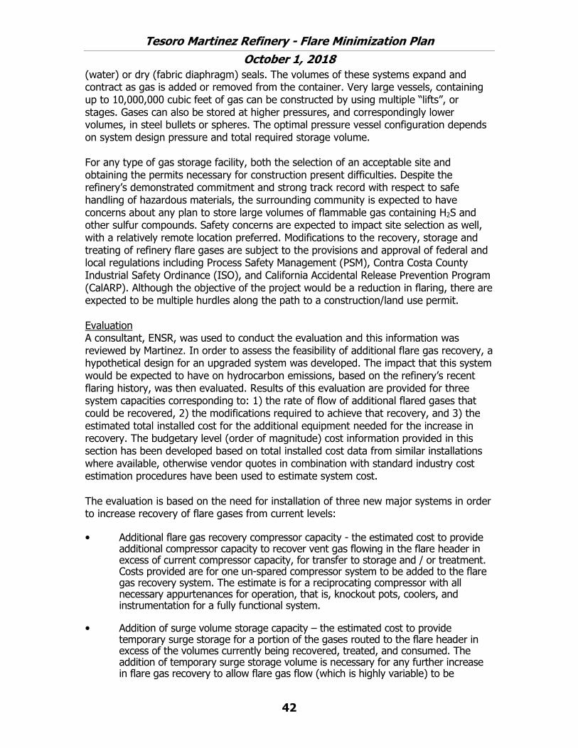
Tesoro Martinez Refinery - Flare Minimization Plan
October 1, 2018
42
(water) or dry (fabric diaphragm) seals. The volumes of these systems expand and contract as gas is added or removed from the container. Very large vessels, containing up to 10,000,000 cubic feet of gas can be constructed by using multiple “lifts”, or stages. Gases can also be stored at higher pressures, and correspondingly lower volumes, in steel bullets or spheres. The optimal pressure vessel configuration depends on system design pressure and total required storage volume.
For any type of gas storage facility, both the selection of an acceptable site and obtaining the permits necessary for construction present difficulties. Despite the refinery’s demonstrated commitment and strong track record with respect to safe handling of hazardous materials, the surrounding community is expected to have concerns about any plan to store large volumes of flammable gas containing H2S and other sulfur compounds. Safety concerns are expected to impact site selection as well, with a relatively remote location preferred. Modifications to the recovery, storage and treating of refinery flare gases are subject to the provisions and approval of federal and local regulations including Process Safety Management (PSM), Contra Costa County Industrial Safety Ordinance (ISO), and California Accidental Release Prevention Program (CalARP). Although the objective of the project would be a reduction in flaring, there are expected to be multiple hurdles along the path to a construction/land use permit.
Evaluation A consultant, ENSR, was used to conduct the evaluation and this information was reviewed by Martinez. In order to assess the feasibility of additional flare gas recovery, a hypothetical design for an upgraded system was developed. The impact that this system would be expected to have on hydrocarbon emissions, based on the refinery’s recent flaring history, was then evaluated. Results of this evaluation are provided for three system capacities corresponding to: 1) the rate of flow of additional flared gases that could be recovered, 2) the modifications required to achieve that recovery, and 3) the estimated total installed cost for the additional equipment needed for the increase in recovery. The budgetary level (order of magnitude) cost information provided in this section has been developed based on total installed cost data from similar installations where available, otherwise vendor quotes in combination with standard industry cost estimation procedures have been used to estimate system cost.
The evaluation is based on the need for installation of three new major systems in order to increase recovery of flare gases from current levels:
• Additional flare gas recovery compressor capacity - the estimated cost to provide additional compressor capacity to recover vent gas flowing in the flare header in excess of current compressor capacity, for transfer to storage and / or treatment. Costs provided are for one un-spared compressor system to be added to the flare gas recovery system. The estimate is for a reciprocating compressor with all necessary appurtenances for operation, that is, knockout pots, coolers, and instrumentation for a fully functional system.
• Addition of surge volume storage capacity – the estimated cost to provide temporary surge storage for a portion of the gases routed to the flare header in excess of the volumes currently being recovered, treated, and consumed. The addition of temporary surge storage volume is necessary for any further increase in flare gas recovery to allow flare gas flow (which is highly variable) to be

Tesoro Martinez Refinery - Flare Minimization Plan
October 1, 2018
43
matched to the demand for fuel gas. The cost used is based on a storage volume equal to the total volume of gas accumulated over one day at the identified flow rate, and is based on recovery in a high pressure sphere system with discharge at a controlled rate back to the flare gas header. Other lower pressure approaches were considered (low pressure gas holder, medium pressure sphere), but for the sizes analyzed a high pressure sphere was identified as the preferred approach based on operational, safety and economic considerations. For the large storage volumes needed for some of the options considered, the cost is based on the use of multiple spheres.
• Additional recovered gas treatment capacity – the cost of additional amine-based treating capacity to process recovered gases for sulfur removal so that they can be burned by existing fuel gas consumers without exceeding environmental or equipment operational limits. Installed cost data for new treatment systems was scaled to estimate the cost of adding treatment for each of the two flow rates identified below. The assumption is that for small increases in treating capacity the existing treater(s) will be modified / upgraded to allow for the increase. No additional cost has been included for expansion of sulfur recovery system capacity.
The table below presents a summary of estimated total installed capital costs for various treatment capacities and scenarios.
Treatment Capacity
(MMSCFD)
Additional Vent Gas
Compressor Capacity
Surge Storage (24 hrs. at flow
rate)
Providing Incremental
Additional Gas Treating for This Flow
If Additional Compressor, Storage and Treating Capacity
Added
2.0 $3,600,000 $5,000,000 $2,000,000 $10,600,000
4.0 $6,700,000 $10,300,000 $3,500,000 $20,500,000
100.0 $160,800,000 $250,800,000 $6,000,000 $417,600,000
In addition to estimating the type and cost of equipment that would be needed to recover additional flare gas, an evaluation was conducted of how much flare gas could practically be recovered using such systems along with an analysis of the anticipated emission reductions for each case. The key points of the evaluation are summarized below: • The 2005 flaring data has been reviewed and, based on the monthly flare report
data, the non-methane emissions per standard cubic foot (scf) of flared gas is 0.00019 lb of non-methane hydrocarbon per scf. This is based on sampling data from reportable flaring events, the flare gas flow data, and applying a 98% combustion efficiency for hydrocarbon.
• Daily average flaring data has been reviewed for the previous calendar year (2005) leading to the conclusion that, on an annual basis, the addition of 2 MMSCFD of additional (unspared) compressor system (including storage and treating) capacity would capture approximately 118 MMSCF of gases currently flared. This evaluation has been performed by totaling the volume of gas currently routed to the flare that could be captured by a system with a flow capacity of 2 MMSCFD. Flow in excess of the 2 MMSCFD rated compressor capacity cannot be recovered by this system. Short duration events have instantaneous flowrates higher than the daily

Tesoro Martinez Refinery - Flare Minimization Plan
October 1, 2018
44
average, so the use of daily data overestimates the volume that the system can capture.
• A similar evaluation has been performed to determine the impact of adding 4 MMSCFD additional flare gas compressor system capacity. This would result in the capture of an additional 49 MMSCF of flared gases on an annual basis.
• Applying the average gas composition and the pounds of non-methane hydrocarbons emitted per scf of flared gas factor to the identified reduction in flared gas volumes, the estimated reduction in non-methane hydrocarbon emissions that could be achieved was estimated at 11.0 tons/year for 2 MMSCFD additional flare gas compressor capacity and 15.6 ton/year for 4 MMSCFD additional flare gas compressor capacity.
• A factor that severely limits the reduction in emissions such a recovery system would achieve in practice is the capability of the fuel gas consumers to accept these gases at the time at which they are generated (from both a volume and quality perspective). The gas storage system which has been specified for each option is necessary if the improvements in flare gas recovery shown have any chance to be realized. However, the composition of the gas could preclude its use as fuel gas and, therefore, the amount of recovered gas is likely overestimated by this analysis. In addition, the 2005 flare data indicates many days where flaring occurred on subsequent days. This would likely prevent the use of much of the recovered gas since it would have to be processed and used by the end of the day to allow accumulation of flare gas on the following day. This is unlikely and would also result in an overestimation of the flare gas actually recovered.
• In order to capture the gas associated with the type of longer duration flaring event that accounts for most emissions from the flare(s) on an annual average basis, a very large capacity for flare gas compression and storage is needed. The third case Martinez has presented, for a system with a capacity of 100 MMSCFD, reflects what would be needed to capture and control all vent gases for this type of event. The system as proposed makes use of 24 flare gas compression systems at 4 MMSCFD each feeding 97 storage spheres, each of which are 60 foot in diameter. The increase in treater capacity is limited to 8 MMSCFD, as flare gas would be stored prior to treatment and worked off through the treater at a gradual rate in line with the ability of the fuel gas system to accept it.
As noted above, any vent gases, whether resulting from an emergency or not, within flare gas recovery compressor capacity is sent to the No. 5 Gas Plant where it is scrubbed and recovered as fuel gas. If there are flare gas flows beyond the capacity of the flare gas recovery compressors, the gas cannot be compressed to the pressure required to enter the Wet gas system at the No. 5 Gas Plant. In addition, even if additional compressor capacity were available, the amount of gas that could be scrubbed and recovered as fuel gas would be limited by the amount of remaining capacity in: 1) the No. 5 Gas wet gas compressors, 2) the fuel gas scrubbing system, and 3) the fuel gas consumers.
Even if only non-emergency gas was considered, non-emergency flare gas would primarily result from planned turnaround events. This gas would tend to be high in nitrogen or hydrogen and, in general, would be relatively low in sulfur. Therefore, scrubbing this gas would not result in significant emission reductions, but would be very

Tesoro Martinez Refinery - Flare Minimization Plan
October 1, 2018
45
expensive to install and operate. Such systems were discussed above and found to not be cost effective. This analysis was done for all flaring (i.e. emergency and non-emergency). Therefore, limiting the operation of such equipment to non-emergency flaring would only make the system less cost effective.
Based on this review Martinez believes that further expansion of systems for the recovery, treatment and use of flared gases is not a cost effective approach to reducing these emissions (see Attachment 9 for cost effectiveness calculations). The major source of flared gases on a volume basis can be attributed to large flow rate flaring events, especially those of extended duration such as may occur during emergency events or prolonged shutdowns where systems within the refinery are out of fuel gas (and / or hydrogen) balance. Martinez believes that this plan addresses such situations, as well as shorter term, smaller flaring events, and provides a cost effective method of eliminating or minimizing flaring during all situations.
Description of Prevention Measures As noted above, the potential causes of vent gas quality or quantity issues are numerous. Releases of vent gas to the flare result from an imbalance between the quantity of vent gas produced by the refinery and the rate at which it can be compressed, treated to remove contaminants (sulfur compounds) and utilized as fuel gas. Situations that have the potential to result in vent gas compositions or flows that would make recovery infeasible can be grouped together based on similarity of cause. These general categories, are:
• Maintenance Activities Including Startup and Shutdown• Malfunctions and Upsets• Emergencies• High Base Load• Reduced Fuel Gas Consumption• Other Causes
Many of these causes are addressed in other sections. Maintenance related flaring is addressed in Section 3.4.1 including issues of vent gas quality and quantity. Malfunction, Upset, and Emergency related flaring is addressed in Section 3.4.3 including issues of vent gas quality and quantity. The remaining categories are addressed in this section.
High Base Load A routinely high flow rate to the flare system can limit the additional amount of flare gas that can be sent to the flare system without flaring. Operations monitors the flow to the flare system and investigates when there are significant changes to the vent gas flow to the flares. By routinely monitoring the flow to the flare system, action can be taken early to identify the cause of the additional vent gas and, to the extent possible, take appropriate action. There are various reasons why high base flows to the flare cannot be reduced at a particular point in time. For example, if the source of the high flow to the flare is required for safety purposes such as the safe depressurization of a unit. Such situations can take several hours or longer and, during this time, Martinez would be unable to reduce the high flare flows. Another example would be if maintenance or an upset resulted in a high flare flow for a limited period of time to safely manage the gas.

Tesoro Martinez Refinery - Flare Minimization Plan
October 1, 2018
46
During that time Martinez would be unable to reduce the high flare flows. If such flows result in a reportable flare event, Martinez will conduct a causal analysis to determine whether the failure to reduce the flow was justified.
Reduced Fuel Gas Combustion Reduced fuel gas consumption can lead to out of fuel balance situations that can cause flaring. This can be caused by energy efficiency improvements or other changes to operating processes. Martinez is committed to improving energy efficiency, while at the same time managing the fuel gas system to reduce the chance of fuel gas imbalance related flaring. As noted previously the Operations Department manages the fuel system to prevent fuel gas imbalance related flaring, to the extent feasible. Operations modifies unit operations at fuel gas generating units to reduce gas make, if needed, to address such situations.
Other Causes If Martinez identifies any other causes that could reasonably result in vent gas composition or quantities that would make recovery infeasible, Martinez will evaluate the cause and determine whether any action is warranted to address the situation. If any additional actions are identified, Martinez will include this information in the next annual update of the flare minimization plan.
Should a situation still result in a reportable flaring event due to issues of gas quality or quantity, Martinez will conduct an analysis of the cause and consider, during that analysis, what further actions may be warranted to prevent a recurrence. That information will be provided to the District.
50 Unit Flare The 50 Unit flare was designed so that it would only be used during situations of upsets, malfunctions, or emergencies. During other situations, the 50 Unit Flare system is designed to recover any flare gas generated and send the recovered gas to the refinery fuel gas system for use in fired equipment within the refinery.
3.4.3 Malfunctions & Upsets
This section addresses situations associated with equipment failure or failure of a process to operate in a normal or usual manner. Such situations are generally referred to as “malfunctions” and “upsets”. During such situations, vent gas flows to the flare system can be large due to pressure relief valves venting to the flare header or various other process streams temporarily routed to the flare to address the upset situation.
Review of Recurrent Equipment Failures or Upsets A review of the reportable flaring events was conducted and there were generally no recurrent failures of equipment or recurrent upset conditions. Martinez had three instances of power outages within the plant that in turn caused flaring due to units shutting down unexpectedly. Martinez is in the process of upgrading the refinery’s switching stations to be more reliable in power interruption situations. These upgrades consist of installing upgraded relays to handle high loads and fluctuations in the electrical system.

Tesoro Martinez Refinery - Flare Minimization Plan
October 1, 2018
47
Description of planned prevention measures The best way to prevent malfunctions and upsets, whether they are recurrent or not, is to take proactive actions to prevent or reduce the chance of such situations. Martinez has a number of programs in place to accomplish this. These include the Mechanical Integrity Program, Predictive and Preventive Maintenance Program, the Maintenance Training Program, and the Operations Procedures and Training Program. Each of these programs is described in more detail below. The purpose of these programs is to ensure that all reasonable efforts are taken to prevent equipment failure and to ensure that the units are maintained and operated by properly trained personnel.
Mechanical Integrity Program The refinery’s Mechanical Integrity Program addresses the integrity of process equipment and instrumentation for safe and reliable operations. The refinery maintenance program covers three types of maintenance: 1) preventative and predictive maintenance, 2) routine maintenance (repair), and 3) turnarounds. Preventative maintenance is performance of equipment inspection and repair based on time and historical knowledge of the equipment. Predictive maintenance involves utilizing technological methods of inspection to determine equipment condition. Preventative and predictive maintenance used in combination determine the inspection and repair frequency of equipment at the refinery. Routine maintenance is the repair or corrective maintenance of equipment as dictated by predictive maintenance, preventative maintenance and equipment condition. A turnaround is maintenance of a process unit on a large scale. A turnaround is the periodic shutdown of a processing unit for cleaning, internal inspection and renewal. The process unit is opened up and its critical components are inspected and repaired during a turnaround. The goal of the Mechanical Integrity Program is to eliminate or minimize equipment failure by maintaining the equipment. This will also eliminate or minimize any releases from that equipment to the flare system.
Predictive and Preventive Maintenance Program
Fixed Equipment: The Inspection Department has trained inspectors for performing inspections on fixed equipment at the refinery. Fixed equipment includes, but is not limited to equipment such as pressure relief systems, fractionators, reactors, separators, drums, strippers, tanks, exchangers, condensers, piping, etc. The Inspection Department maintains a current list of all fixed equipment, categorized by process, which includes information on the last inspection, next planned inspection and inspection frequency. Records of all equipment inspection are retained for the life of the equipment. The Inspection Department also has a written procedures manual, which contains written details on how to perform certain inspection techniques used to determine equipment serviceability. Examples of techniques used by Inspectors include: visual weld inspection, dry magnetic particle testing, wet fluorescent magnetic particle testing, liquid penetrant examination, Eddy current tube examination, IRIS tube inspection, ultrasonic testing, and radiographic viewing. The Inspection Manual also details procedures regarding how to perform an inspection for certain pieces of equipment. Examples include instructions on how to inspect piping, boilers, air receivers, pressure vessels, furnaces, and exchanger tube bundles. Inspection

Tesoro Martinez Refinery - Flare Minimization Plan
October 1, 2018
48
frequency and methods of inspection are performed according to Industry Codes and Standards and the California State (Cal-OSHA) Safety Orders. For example, pressure vessel inspection is performed according to API Standard 510 (see next paragraph for more information on API 510). The Inspection Procedures are reviewed regularly for accuracy. Any changes to Inspection Procedures are managed through a revision process for tracking changes. The Inspection Procedures Manual is available to employees both electronically through a computer shared-drive and in hard copy at their office.
API 510 inspection code provides a process to ensure that the in-service inspection, repair, alteration, and re-rating activities for pressure vessels and the pressure-relieving devices protecting these vessels are conducted properly. By following this inspection standard, the risk of an unexpected vessel failure is significantly reduced. Pressure vessels that remain in a condition of being suitable for operation reduce the likelihood of taking the vessel out of service during the unit run, which can potentially take the unit off-line. If the vessel needs to be de-pressured safely and quickly, then the potential to flare is a more likely scenario due to the sudden increase in flare header flow and pressure required which may exceed the flare recovery capacity and the flare seal system resulting in a flaring event. Keeping a pressure vessel operational in a “normal” mode reduces the potential for flaring.
Rotating Equipment: The Rotating Equipment Department performs all inspections and repairs on rotating equipment at the refinery. Rotating equipment includes pumps, compressors, fans, blowers, turbines, engines, gear boxes, motors, etc. The rotating equipment group consists of Machinists, Machinery Field Specialists, Vibration Specialists, and Rotating Equipment Engineers. The Rotating Equipment Department maintains a current list of all rotating equipment that is categorized by type of equipment. Rotating equipment is inspected and tested using lubrication checks, oil analysis, visual inspections, vibration monitoring and testing mechanical safety devices. The frequency of these tests and inspections is based upon industry codes and standards as well as type of service. For example, steam turbines are inspected and tested according to the API Standards 611 and 612. Inspection records are maintained on file as hard copies. Vibration records are entered into a computer database for tracking. The Rotating Equipment Department also has a written procedures manual, which contains up-to-date written details on how to perform rotating equipment inspection and tests. The procedures are reviewed regularly and changes are tracked through a revision process.
Maintaining rotating equipment in good operating condition reduces the chance of malfunctions or upsets that can result in flaring. Also, preventive maintenance programs will tend to identify potential problems prior to failure and allow issues to be addressed in a planned manner. This reduces the chance of an unplanned, upset condition that can result in flaring.
Instrumentation and Electrical Equipment: The Instrument and Electrical Department (I&E) performs all inspections and repairs on instrumentation and electrical equipment at the refinery. This type of equipment includes, but is not limited to, transmitters, controllers, control valves, Distributed Control Systems, analyzers, interlocks, relief valves, power distribution systems, motors, alarms, and

Tesoro Martinez Refinery - Flare Minimization Plan
October 1, 2018
49
programmable logic controllers. The I&E group consists of Electricians, Instrument Mechanics, Analyzer Mechanics and Distributed Control System Technicians. I&E maintains a current list of all electrical equipment and instrumentation. I&E has 13 programs dedicated to predictive and preventative maintenance of instrumentation and electrical equipment. The thermographic survey program is an annual performance of a survey to identify any hot spots in the power distribution system for repair. The Motor Management program addresses motor reliability. The transformer program includes inspection and testing of transformers. The UPS/Battery Program requires quarterly testing of these power sources. The Substation and Switching Station Program addresses inspection and testing of electrical power distribution stations to ensure reliability. The Insulator Washing Program covers the cleaning of high voltage insulators. The Pole Inspection Program covers annual inspection of all power poles in the refinery. The Analyzer Program covers calibration and testing of analyzers, with the results of the tests tracked by computer to predict maintenance requirements. The Vibration Program is performed on motors with the Rotating Equipment Group. The Cathodic Protection System is checked through a monthly inspection program. Control valves are serviced through a Control Valve Management Plan, where a flow-scanning system is used to quantify and record the control valve performance. The Relief Valve Servicing program covers refinery pressure relief systems. The Essential Instrument Program addresses inspection and repair of critical instrumentation. In addition, the Distributed Control System Technicians inspect and test the computer systems that control refinery processes. The test frequencies are specified by instrumentation type and manufacturer specifications. Inspection and test records are maintained on file and tracked by database. I&E has written procedures for performing inspections and tests. These procedures are reviewed regularly and changes are tracked through a revision process. Due to the rapid technological expansion occurring in instrumentation and digital control systems, I&E has more frequent personnel training and procedure reviews than other areas.
Maintaining instrumentation and electrical equipment in good operating condition reduces the chance of malfunctions or upsets that can result in flaring. Also, preventive maintenance programs will tend to identify potential problems prior to failure and allow issues to be addressed in a planned manner. This reduces the chance of an unplanned, upset condition that can result in flaring.
Repair Routine or corrective maintenance of equipment is performed by experienced Craftspeople. Craft specialties include Boilermakers, Welders, Pipefitters, Exchanger Shop Mechanics, Mechanics, Machinists, Riggers, Carpenters/Builders, Compressor Mechanics, Valve Mechanics, Instrument Mechanics and Electricians. Corrective maintenance is performed on equipment as dictated by predictive maintenance, preventative maintenance and equipment condition. Operator surveillance during their routine inspections of the units is also used for determining the need for repair of equipment. Documentation of repairs is developed and maintained in the applicable equipment folders for the life of the equipment. The repairs may be performed in maintenance shops or in the field. The refinery has specialized repair shops for carpenter work, welding, machine work, instrument and electrical repair, and exchanger repair. Inspectors perform inspections and tests on fixed equipment and maintenance craft personnel perform the repairs. These repairs are typically performed in the field. The Maintenance Department

Tesoro Martinez Refinery - Flare Minimization Plan
October 1, 2018
50
has written procedures for corrective maintenance of equipment. These procedures are available on the refinery intranet as well as in hard copy. Rotating equipment is both inspected and repaired by Rotating Equipment Department personnel. These repairs may be performed in a shop or in the field by Machinists or Machinery Field Specialists. The Rotating Equipment Department has written procedures for repair of the equipment. These procedures are reviewed annually and tracked through a revision process. I&E repairs electrical equipment, instrumentation and relief valves. These repairs may be performed in the shop or in the field by the appropriate Craftspeople. I&E has written procedures for repair of their equipment. These procedures are regularly reviewed and changes are tracked through a revision process.
Repair work is planned by maintenance planners. They develop detailed plans for conducting repairs in a safe manner. Depending upon the scope of work, the proper information and materials are assembled for the repair work to proceed. In addition, the appropriate safe work permit requirements are identified for the job. Upon completion, repair records for equipment specific repairs are retained in hard copy or tracked by computer database.
Equipment repairs minimize flaring by properly maintaining equipment to minimize the chance of an upset or unplanned shutdown that can result in flaring.
Turnaround A turnaround is maintenance of a process unit on a large scale. A turnaround is the periodic shutdown of a processing unit for the cleaning, inspection and renewal of worn parts. The process unit is opened up and its critical components are inspected and repaired during a turnaround. Due to the size of the project, turnarounds take 6-24 months of planning. Three criteria determine the frequency of unit turnarounds; they are the type of unit, the history of the unit and specific government regulations. Typically, units undergo a turnaround every two to five years. Large unit turnarounds may require the use of 1000 contract craftspeople to complete the repairs.
Maintenance turnarounds minimize flaring by properly maintaining equipment to minimize the chance of an upset or unplanned shutdown that can result in flaring.
Maintenance Training Program Staff training helps ensure that activities such as equipment inspection, problem identification, repairs and quality control of all equipment are conducted properly and that problems are identified and addressed to keep the equipment functioning properly. Properly functioning equipment reduces the likelihood of equipment malfunctions that can cause unit upsets which can result in flaring. This will also reduce the chance of having to take equipment off-line during the unit run, which can potentially lead to a flaring event.
Maintenance Craftsperson Training The refinery employs experienced Journey-level Craftspeople in a number of disciplines to perform maintenance at the refinery. Craft disciplines include Boilermakers, Welders, Transportation (drivers), Pipefitters, Exchanger Shop Mechanics, Mechanics, Machinists, Vibration Specialists, Riggers, Carpenters/Builders, Compressor Mechanics, Valve Mechanics, Instrument Mechanics and Electricians. The refinery hires only Journey-level

Tesoro Martinez Refinery - Flare Minimization Plan
October 1, 2018
51
craftspeople. All Craftspeople must pass a written and practical exam to demonstrate their skills prior to hire. All Craftspeople are trained on the overview of the refinery processes. On a regular basis, refresher training is performed and conducted in modules. These training modules may include, but are not limited to: forklift operations, respirator fit testing, fresh air, blinding, torqueing, hose use/selection, gasket selection, fall protection, lead abatement, asbestos, lock-out/tag-out, hazardous energy, confined space, hot work, repacking valves, rebuilding site glasses, bleeder reamer use, turbine repair, laser alignment of equipment, staging/scaffolding, rigging/crane, highlift, and leak repair. During the lock-out/tag-out training module, there is an emphasis on understanding the hazardous energy sources. All Craftspeople must complete an exam at the conclusion of each training module. Vibration Specialists responsible for performing predictive and preventative maintenance on rotating equipment have been certified in their craft by attending in-depth training courses from the Vibration Institute and/or manufacturers’ training courses. Machinists who perform vibration analysis on rotating equipment have received 12 hours of classroom training in addition to field training. The instrument mechanics and electricians have skills training annually, including a specialized Computer Based Training (CBT) for their craft. Under special circumstances in 1999, all refinery Maintenance Craftspeople repeated all training modules described above (with the exception of vibration training). Training records are retained. Inspector Training Inspectors perform inspections of structures and fixed equipment to ensure the integrity of the equipment, and thereby, the safety of personnel and property. The inspection personnel receive specialized training to assure that they are able to successfully perform their job. All Inspectors must have five years’ experience in operations, welding and/or boilermaker craft. They must pass a written exam as well as a vision test. The Inspector initially is trained in a company developed training program involving in-house and off-site training. The course curriculum is focused on non-destructive testing and equipment visual inspection. Specific courses may include: Introduction to non-destructive testing, visual weld inspection, radiation safety and radiographic examination, math and physics for industrial technology, ASME pressure vessel and boiler codes, magnetic particle examination, ultrasonic examination-thickness gauging, color contact penetrant examination, API 510 on pressure vessels, API 570 on piping and API 653 on tanks. Certification of course completion is performed by written exam. All training is paid for by the refinery. The Inspector training is compliant with ASNT SNT-TC-1A and API guidelines. Recertification, as specified in ASNT SNT-TC-1A and API guidelines, occurs every 3 to 5 years depending on the method and/or certification. Inspector training is tracked by the Inspection Department by database, including when training has been completed and refresher training is due. In addition, hard copies of all Inspector certifications are kept on file. Training records are retained. General Safety Refresher Training In addition, all Maintenance Craftspeople and Inspectors must complete an annual CBT and classroom training that addresses chemical hazards, the emergency action plan, electrical safety awareness, safe work permitting, Personal Protective Equipment (PPE), and respiratory protection. The training records of all maintenance personnel, except Inspection, are kept by the Training department.
Tesoro Martinez Refinery - Flare Minimization Plan
October 1, 2018
52
Quality Assurance The quality of maintenance repair work on fixed equipment is verified by Inspectors. The Inspectors perform or oversee specific tests after the repair is complete to assure that the repair has been performed properly and with appropriate materials. The nature of the tests used for quality assurance depends upon the type of work performed and is typically specified by an Inspector. To assure the proper material has been used in building or repairing a process, the refinery has a Positive Materials Identification Procedure. This procedure involves the use of an analyzer capable of identifying metal alloys. Rotating equipment quality assurance is performed by Supervisors. They perform visual inspections, pressure testing (where and when applicable) and start-up checks. In addition, spare parts original manufacturer’s number is tracked along with the manufacturer provided documentation (material certification papers) to ensure the right parts have been installed into the proper service. Instrument and Electrical repair quality is assured by strict use of original equipment manufacturer spare parts. Repair of relief valves are performed by VR qualified shops, these specialized shops have been certified by a national board to perform work on relief valves.
Quality control of repairs and maintenance helps to ensure that the repairs and/or replacements of components are correct and meet all requirements necessary for the particular job. This reduces the chance of an unplanned outage of the equipment which can cause a unit upset or shutdown which, in turn, can result in flaring.
Operations Procedures and Training Program Operating Procedures The refinery has written Operating Procedures for all operating units. The purpose of the Operating Procedures Program is to develop, implement and maintain operating procedures that provide clear instructions for safely conducting activities involved with refinery processes. Operating Procedures are organized into Operating Procedures Manuals for each process unit. In addition, there is an Operating Manual for each unit. Every Operating Manual contains all the process information, engineering data, and reference sources that is required to operate the unit in a safe, efficient, reliable and environmentally sound manner.
The written Operating Manuals were developed from a standard template. All Operating Manuals follow a consistent format that is divided into six sections. There is an introduction section, a process safety and environmental section, an equipment description section, a process control variable section, a troubleshooting section and a failure prevention section. In addition, both the Operating Procedures and Operating Manuals contain information so that the Operator can take appropriate action to safely perform any of the following: an initial unit start-up, normal operation of the unit, shutdown of the unit during an emergency, operation of the unit during an emergency, a normal shutdown of the unit, a startup after a turn around and a startup after an emergency shutdown. The Operating Procedures Manual and Operating Manual also contain information regarding the consequences of deviating from normal operating parameters and the steps to correct deviations and avoid deviations. In addition, the Operating Procedures Manual and Operating Manual contain information about the

Tesoro Martinez Refinery - Flare Minimization Plan
October 1, 2018
53
process safety systems and how they function. Written temporary Operating Procedures are developed if needed.
The initial development of the Operating Procedures involved Operators, Unit Supervisors, Shift Supervisors, and outside Contractors, all of whom are collectively referred to as Subject Matter Coordinators (SMCs). The SMCs wrote the initial versions of the Operating Procedures. Review and certification of the Operating Procedures occurs at regular intervals. The Area Supervisor is responsible for the review and certification of their completeness and accuracy. Operators are typically consulted during this review. During the review process, revisions to the Operating Procedures may be warranted. Any revisions to the Operating Procedures are managed through Management Of Change and operators are trained on the revisions. Hard copies of Operating Procedures are kept in each control room and at the training center. In addition, electronic copies are available on the refinery intranet.
The refinery has a permitting program to address the safe work practices involving lockout/tagout, confined space entry, opening process equipment/piping and access of personnel other than operators to the process area. The refinery also addresses Hot Work by permit. The permit template was used to address safe work practices so that maintenance work would be planned and performed in a consistently safe manner. The content of the permit forms is in compliance with Cal-OSHA regulations specific to each of the areas previously mentioned. The safe work practices and policies are available on the refinery intranet for all employees. In addition, hard copies of the policies and permits are available in unit control rooms and at the Shift Superintendent’s office. Safe work practice permitting is continuously audited by the Health and Safety Department and the results are posted monthly on bulletin boards refinery-wide for employees to read. The Field Safety Supervisor manages all changes to the safe work practices and permits. Employee involvement on development and maintenance of the safe work practices occurs through the Joint Health and Safety Committee. Employees are informed of changes through the weekly/monthly safety meetings, bulletin board postings, email distribution and other appropriate methods.
Eliminating or minimizing flaring is an ongoing general operating practice. However, this has not yet been included in all startup or shutdown procedures (many operating procedures do not involve flaring issues, so startup and shutdown procedures are more pertinent). At least 20% of the shutdown procedures currently include references to eliminating or reducing flaring. As the startup and shutdown procedures are revised, such references will be included.
Operating procedures reduce flaring by instructing operators to route streams to alternate locations during depressurization of equipment, by instructing them to depressure slowly, and by instructing them to notify shift supervision before conducting depressurization operations.

Tesoro Martinez Refinery - Flare Minimization Plan
October 1, 2018
54
Operator Training The objective of the training program is to ensure that employees involved in the operation and maintenance of processes are trained in the tasks and information necessary to safely and effectively perform their work.
An awareness of the importance of minimizing flaring may be the most effective means of actually reducing flaring. Operators who are trained how to operate their units safely and efficiently, depressure equipment according to operating procedures, and communicate with other units effectively play a vital role in the overall goal to reduce and control flaring activities. By the operator being aware of the goal to eliminate or reduce flaring, actions will be taken consistent with that goal. Effective communication between units helps to coordinate what is being sent to the flare and minimize the chance of exceeding the flare recovery system capacity. In addition, operator training reduces the chance of upsets or other unplanned events that can result in flaring.
Initial Operator Training The new Operators begin with six weeks of classroom training. The classroom training covers safety training, reviewing safe work practices, respiratory protection, PPE, hearing conservation and hazard communication program (this program covers how to find and use MSDSs and other portions of PSI). The new operators are also trained to the First Responder Operations Level as required by the HAZWOPER regulations. This training covers defensive actions in the event of an accidental release. In addition to the HAZWOPER training, the new Operators also receive Incipient Fire Training. The curriculum also covers a general introduction to refinery processing, followed by training modules on refinery equipment, including pumps, compressors, heat exchangers, distillation towers, valves, instrumentation, furnaces, boilers, cooling towers and electrical systems.
After the classroom training is complete, new operators begin practical training in the field. They study the Operating Procedures and Operating Manuals specific to the unit on which they are assigned. They become skilled at the details of their job, including how to perform procedures. They also learn more about their specific process unit, including its process chemistry. The new operators learn the operational details covered in the six sections of the unit’s Operations Manual, with particular emphasis on process control and safety systems. The process control emphasis is on critical operating limits (COL), the consequences of operating outside the COL and how to bring the unit back under control if it has deviated outside of the COL. The safety system emphasis focuses on the importance and function of the unit safety systems.
The refinery has several units with state-of-the-art computer controls. The Operators assigned to these computer-controlled units receive additional training on computer simulators. The simulators allow the operators to practice controlling the process units under a variety of events. The simulators are a dynamic training tool, they can mimic the entire process unit and show the Operator the consequences of changing variables during process operations. Some of the unit simulators also perform scenario training. The scenarios can mimic process upset conditions that would require the operator to safely shut-down the unit. The Operator can then practice how to safely restart it.

Tesoro Martinez Refinery - Flare Minimization Plan
October 1, 2018
55
Upon completion of the initial training, operators are given a written exam and a practical exam. The written exam covers information specific to the Operations Manual in their unit. The practical exam addresses the procedures they perform and specific details of their unit. Finally, the new operator must pass the qualification process, which is similar to an oral exam, where they demonstrate the skills they have learned to be a qualified operator. This completes the operator’s certification of training.
Refresher Operator Training Operator refresher training is conducted every three years. It covers the procedures and operations manual of the specific unit on which the operator is assigned. As part of their refresher training, operators must pass a written exam and a practical exam in addition to the qualification process. In addition, each year all employees, including operators, complete CBT modules on many of the topics covered in the initial operator training course. Under special circumstances in 1999, all refinery operators repeated the initial operator training and were re-certified in the same manner as described previously under initial operator training.
Training documentation: The Training Department maintains records on all employee training. Initial Operator training and refresher training is tracked through a database. The database is programmed with the required training curriculum for each employee. Employee training and testing is entered into the database upon its completion; this includes training on CBTs, classroom, as well as any written or verbal test results. Training records for certain courses or safety meeting attendance are kept in hard copy in a central filing system.
In spite of such extensive efforts, equipment malfunction and upset situations can still occur. Should a malfunction or upset situation occur that results in a reportable flare event, Martinez will conduct an analysis of the cause and consider, during that analysis, what further actions may be warranted to prevent a recurrence. That information will be provided to the District.
3.4.4 Other Potential Flaring Events
Should a reportable flare event occur due to any other cause not already noted in this FMP, Martinez will conduct an analysis of the cause of that event and consider, during that analysis, what further actions may be warranted to prevent a recurrence. That information will be provided to the District.
Flare Testing From time to time, testing of a flare may be required to ensure that it is operating or will operate properly. Typically this is done after construction of the flare or any significant repair or maintenance to a flare. During these situations it is important to conduct a controlled test to ensure that the flare or flares will function properly. For example, if a flare tip required replacement (due to corrosion or some other cause), a test of the flare might be performed to ensure that the replacement tip would perform properly during a flaring event. Historically, such testing has rarely been required. The test is typically performed by sending fuel gas to the flare. Typical flow rates during the test are about

Tesoro Martinez Refinery - Flare Minimization Plan
October 1, 2018
56
5- 10 MMSCFD and the typical time to conduct a test is about 15 minutes at a time. Martinez will provide a test protocol to the BAAQMD for approval prior to conducting any flare tests. Delayed Coker Flare Prevention Measures As a part of the design of the Delayed Coker Revisions, prevention measures were included in the design and operation to minimize or eliminate flaring. These measures ensure that all normal operations and maintenance venting is routed to the wet gas system instead of the flare system. Therefore, there is no impact of routine operation and maintenance flare gas flow from the Delayed Coker on the refinery flare gas recovery. This is described in more detail below. In the delayed coker, coke is produced in four large coke drums. The coker feed, vacuum residuum, are fed to the coke heaters from the fractionator. The coker heaters heat the feed to approximately 950° F. The bottom of the fractionator serves as a surge tank for the coke heater charge pumps. The heated feed is sent to two of the coke drums. Upon entering the lower pressure of a coke drum, the cracked hydrocarbons flashes and passes overhead, is quenched with heavy coker gas oil, and then enters the bottom of the fractionator. The finely divided carbon particles formed in the cracking of the large chain hydrocarbons remain in the coke drum, coalesce and form solid coke particles. These particles solidify in a matrix and build up in the drum, filling it to a predetermined level. Two drums are online filling with coke while the other two are offline either having the coke removed from the drum or being prepared to be switched back to online. A filled coke drum is stripped of residual vapors with steam, and then quenched with water. The vapors produced by quenching are routed to the new quench tower closed blowdown system to remove coke particles and oil droplets prior to being condensed in air-cooled condensers. The remaining vapors are routed to the existing wet gas compressors at No. 5 GP and used for fuel gas and products (propane and butane). The use of the quench tower closed blowdown system allows for the recovery of hydrocarbon from the coke drums prior to switching them off line and removing or cutting the coke. This design was developed so that the vapors would not need to be sent to the flare. In addition, the operating procedures for the delayed coker startups and shutdowns do not require flaring during the startup of the unit. Any hydrocarbons generated during startup or shutdown are recovered in the wet gas compressors at No. 5 GP. In addition, venting associated with maintenance operations will also be sent to the wet gas system and will not be sent to the flare system. The flare system only receives vent gases associated with an upset or breakdown situation. Martinez has also tied the Coker Flare into the existing flare system, and the associated recovery compressors, to recover any small leaks or minor process upsets that may occur to avoid flaring for these events. Lastly, the other general prevention measures also apply to the Coker Unit. The Coker Modification Project included various connections to the flare header, through the new flare knockout vessel. These include hydrocarbon relief valves (safety control and manual) and various hydrocarbon drains used to hydrocarbon free the equipment

Tesoro Martinez Refinery - Flare Minimization Plan
October 1, 2018
57
prior to maintenance. More specifically, there are Coke drum relief valves, Fractionator relief valves, fuel gas relief valves, Blowdown Quench System relief valves, and Strainer relief valves. There is also a valve to route Settling Drum Off Gas to the flare system (which is normally closed with the off gas normally sent to the No. 5 GP) and a natural gas purge to ensure the flare header is free of oxygen (which is recovered by Flare Recovery Compressors).
In addition, there are various pump vents/drains, heater tube vents/drains, and strainer drains that are routed to the flare header. There are also connections to cross connect the various flare headers. The new 42” flare header is designed for a maximum rate of 266 MMSCFD.
The Coker Modification Project relief valves are routed to a flare knockout vessel and the gas is routed to the refinery flare system. The Coker Flare is required to ensure that, during all relief events, there is adequate flare capacity.
The Coker Flare is operated as a part of the existing, staged main refinery flare system. Additional details on the seal pot levels and header system are provided in Section 3.1.1 of the FMP and the main flare simplified flow diagram.
The operation of the Coker Flare is consistent with flare minimization. The addition of the Coker Flare to the refinery main flare system retains the overall flare minimization of the flare system as a whole. There is no routine flow to the flare system from the Delayed Coker and all the existing flare minimization efforts, including the flare gas recovery system, will continue.
The Coker Modification Project directionally reduced the chance of a fuel gas imbalance situation, which reduced the chance of flaring. The Delayed Coker produces less fuel gas than the historic Fluid Coker. In addition, the two furnaces at the Delayed Coker use a combination of fuel gas and natural gas, which increased fuel gas use. (The Fluid Coker combusted coke for heat whereas the Delayed Coker uses fuel gas/natural gas for heat.) Therefore, since less fuel gas is produced and there is more fuel gas used in the refinery, the chance of a fuel gas imbalance situation is reduced (i.e. a situation where there is temporarily more fuel gas being produced than fuel gas being consumed).
The Delayed Coker generates fuel gas continuously. However, when switching a drum, the amount of gas make reduces to about 75% of the previous amount (since the drum being switched into is not quite as hot as the drum that had been online previously). Therefore, additional natural gas needs to be added for about 2 hours after a drum switch. This serves to further reduce the chance of a fuel gas imbalance situation that could result in flaring.
50 Unit Flare Prevention Measures As a part of the design of the 50 Unit Flare, prevention measures were included in the design and operation to minimize or eliminate flaring. These measures ensure that all normal operations and maintenance venting is routed to the fuel gas system instead of the 50 Unit Flare. Therefore, there should be no flaring associated with routine operation and maintenance at the 50 Unit. This is described in more detail below.

Tesoro Martinez Refinery - Flare Minimization Plan
October 1, 2018
58
The 50 Unit Flare was installed as a part of a project to replace the 50 Unit Atmospheric Blowdown Tower. Various maintenance streams and pressure relief valves had been routed to the atmospheric blowdown tower. This project removed the existing atmospheric blowdown tower and replaced that system with the 50 Unit Flare and flare gas recovery system. The 50 Unit flare gas recovery system includes a flare gas header and compressors to recover flare gas generated and send it to the refinery wet gas system where it is treated and used as fuel gas. The 50 Unit flare gas recovery system has been designed to handle scheduled routine maintenance, as well as scheduled major turnaround maintenance. The system includes a small compressor to handle the day-to day small maintenance and purge streams that may be generated. In addition, the existing spare 50 Unit wet gas compressor has been lined up and used for recovery of the vapors during de-pressuring and equipment steam-out of large process equipment during and outside of the turnarounds when non-condensable hydrocarbon loading is relatively high in the 50 Unit flare gas recovery system header. The existing spare wet gas compressor will also serve as a common spare between the flare gas recovery service and the wet gas service. Since equipment de-pressuring and steam-out operations are well planned operations, sufficient time is available for changing over from the small flare gas recovery system compressor to the existing wet gas compressor and vice versa. The existing spare wet gas compressor is expected to be used for the flare gas recovery service only for short periods of time during the beginning of the steam-out operation, when non-condensable hydrocarbons are present in relatively large quantities. Control valves have been provided on the steam-out lines from large process equipment for controlling steam-out rates to minimize the chance of the 50 Unit flare liquid seal being broken during the steam-out operations. A spill-back control valve has also been added to the design to help keep the wet gas compressor suction pressure, when in flare gas recovery service, at a constant pressure lower than the normal flare gas recovery system pressure. In addition, a steam condenser has been added to the system design. This condenser allows the steam sent to the flare recovery system during maintenance steam out situations to be condensed, reducing the overall flow rate to the flare gas recovery system. Small Flare Events GER reviewed small flaring events from 7/1/15 through 6/30/16 that, due to the total volume or low emissions, did not reach the trigger levels for a flare causal analysis. An analysis of the average emissions associated with these five small flare events was conducted. Days with flare events that triggered a flare causal analysis and days of no flaring were excluded from this review. The average flare emissions per small flare event day were 19 lb/day of methane, 76lb/day of non-methane hydrocarbon, and 107 lb/day of SOx. One of the small flare events was related to issues with the refinery fuel gas mixpot seeing increased wet gas production, which releases the excess gas to the flare header under pressure control. Other incidents were related to general unit shutdowns and startups.
Tesoro Martinez Refinery - Flare Minimization Plan
October 1, 2018
59
Nonetheless, a review of the causes for such events was conducted by interviewing key Operations personnel in each of the operating areas to identify situations that they recalled leading to small flare events. Planned and completed actions to eliminate or reduce flaring from small flaring situations have been noted in Attachment 16.
3.4.5 Summary GER believes that the prevention measures described in this FMP are the most effective in minimizing flaring from the refinery. No other measures were considered to reduce flaring, beyond what is contained in this FMP, with one exception. An attempt was made to use a chemical additive that reportedly might improve the removal of hydrocarbon from vessels prior to opening the vessels to the atmosphere. If successful, this would have reduced the amount of purge gas that would need to be sent to the flare to comply with the requirements of the District’s vessel depressurization rule (Regulation 8, Rule 10). The chemical addition was tried during a recent turnaround at the No. 3HDS unit. Unfortunately, the results of the test indicated that the use of the chemical did not substantially improve our ability to remove hydrocarbon from the vessels or reduce the time it took to gas free the vessels. Therefore, the test was deemed unsuccessful.
Work practices to reduce flaring are written in procedures. In addition, Martinez has developed a procedure to consider flaring impacts and potential mitigations during more routine maintenance efforts. Martinez has modified the past maintenance project planning process to evaluate whether certain maintenance activity could reasonably result in flaring and, if so, consider what actions might be taken to reduce or eliminate the flaring. As noted above, should significant flaring (i.e. flaring over 500,000 scf/day) still occur, a causal analysis will be performed to determine whether there are reasonable methods to reduce or eliminate such flaring in the future. There are no other new or revised procedures planned for implementation to reduce flaring.
As noted in Section 3.4.3, Description of planned prevention measures, during the pre-planning process for planned major maintenance reducing process flow rates to eliminate or reduce flaring will be considered. Since every planned major maintenance activity is unique (i.e. the equipment being shut down, units being shut down, and other operating parameters at the time of the shutdowns), Martinez believes that this method will be the most effective in identifying methods to eliminate or reduce flaring. As noted in Section 3.4.2, many of the gas quality or quantity issues are related to planned major maintenance activities. The remaining causes of gas quality or quantity issues are: 1) malfunction, upset, or emergency (as described in Regulation 12-12-201) situations, 2) high base load situations, 3) reduced fuel gas consumption situations, and 4) possible other causes. During malfunctions, upsets, or emergency situations, reducing process flow rates to eliminate or reduce flaring will be considered when the situation is stable and any issues of safety have been addressed. High base load situations would not normally result from unit rate issues. However, if in the specific situation reducing process flow rates has the potential to eliminate or reduce flaring, it will be considered at that time. During situations when the fuel gas system is out of balance, reducing process flow rates to eliminate or reduce flaring will be considered (when the situation is stable, since these situations can occur during malfunction, upset, or emergency situations). Lastly, if any other cause is identified that results in flare gas quality or

Tesoro Martinez Refinery - Flare Minimization Plan
October 1, 2018
60
quantity issues, as a part of the evaluation noted in Section 3.4.4, reducing process flow rates to eliminate or reduce flaring will be considered.
4.0 Capital and Operating Cost
In order to allow estimation of total installed capital cost for additional flare gas compressor capacity, a series of cost curves for each of the necessary components of the system have been developed. This section defines the design of the “model” systems used to develop cost data and then presents the data.
4.1 Operation of Flare Gas Systems with Incorporation of Storage
The systems that ENSR developed pricing for are shown in the attached sketches. The sketches show a very much generalized flare gas recovery system and do not represent the actual configuration at any refinery. A typical flare gas recovery system is shown in Attachment 10. Operation of these systems is envisioned as follows:
Both existing and new flare gas compressors (exclusive of any spare units) would operate continuously. During normal operation the volume of gas they are capable of drawing from the flare gas header would be greater than the volume available, so a portion of the discharge volume would be recycled to the suction side of the compressors via a pressure control loop. Inter-stage cooling would prevent the temperature rise from exceeding design limits. Normally the volume of gas from the flare gas header and other process sources would be less than the total needed for process heaters and boilers. Natural gas would be used to make up the shortfall.
System with Gas Holder At normal flow rates, pressure in the flare gas header is set by the suction-side pressure control system for the flare gas compressors as described above. When the flow of flare gas exceeds the volume that can be handled by the flare gas compressors, treaters and fuel gas system, the pressure in the flare gas header increases. This increase in pressure is sufficient to begin to lift the “piston” in the gas holder, effectively storing any excess flow that the recovery system cannot handle. Once the gas holder fills completely, if flare gas flow rates continue to be in excess of what the recovery system can handle, the pressure in the header will continue to rise until it exceeds the pressure corresponding to the depth of the flare seal, allowing any excess gas to be flared. As the flow of gas to the flare gas header decreases, first flaring will cease, then as the pressure in the header continues to fall, gas will flow from the gas holder to the suction side of the flare gas compressors, until the gas holder has been emptied. This system is shown in the figure titled “Flare Gas Recovery with Gas Holder” (see Attachment 11).
System with Storage Sphere If the volume of gas supplied to the fuel gas header were to exceed fuel requirements at the heaters, pressure would rise in the fuel gas header and gas would be diverted from the flare gas compressor outlet to the storage sphere. This system is shown in the figure titled “Flare Gas Recovery with Storage Sphere” (see Attachment 12). If the pressure in the sphere were to reach the compressor discharge pressure, it would stop filling, and the situation would be equivalent to that which exists with the current system when flare gas compressor capacity exceeds demand.

Tesoro Martinez Refinery - Flare Minimization Plan
October 1, 2018
61
Gas would be returned from the sphere to the flare gas header based on header pressure. The flare gas compressors are configured to control inlet pressure at a point below where the flare seal would be broken. The storage sphere would have a pressure control system that would allow gas to flow from the sphere to the flare gas header when the header pressure was at or below a set point slightly higher than the flare gas compressor suction-side set point. This would have the effect of keeping the flare gas compressors loaded at their rated capacity whenever there is excess flare gas in the sphere to work off. When the flow of flare gas to the flare gas header exceeds the volume that can be accommodated by the treaters, process heaters and boilers, the pressure in the flare gas header would rise and flow from the sphere to the header would be stopped by the control system.
4.2 Flare Gas Storage System Options Total Installed Cost Estimation
A series of curves showing total installed cost (TIC) for installation of additional flare gas recovery capacity are presented in this section. They were developed primarily using cost data compiled from projects completed at U.S. refineries and shared with WSPA. This information was supplemented using current quotations from equipment vendors. Please note that steel costs have been escalating quickly and are continuing to increase. Therefore, the steel costs used in this analysis are likely understated. In addition, a significant amount of construction cost data used for this analysis was for construction outside of California. The cost of construction in California, and particularly the Bay Area, is significantly higher than in other regions of the country. Therefore, the construction costs used in this analysis are likely understated, as well.
Vessel Costs Cost estimating curves (see Attachment 13) were developed for three flare gas storage options. The curves are based on gas storage in: a 40-psig spherical tank, a 120-psig spherical tank, or a conventional gas holder.
The spherical tank costs were based on quotes from CB&I for a 60-ft diameter tank, at operating pressures of 40 psig and 120 psig. A 60-ft diameter tank was used as it is near the largest economical size for a spherical tank. Estimated total installed costs include stress relief, foundations, erection, and painting. In developing the cost curves, storage volumes greater than the 60-ft diameter tank can provide are achieved by using multiple tanks. Therefore, cost data points for storage volumes greater than that for a 60-ft diameter tank were calculated based on multiplying the number of tanks by the cost for a single tank. For storage volumes less than that of a 60-ft tank, the 6/10ths rule was used to calculate the cost for that volume. The 6/10ths rule takes the original cost, multiplied by the ratio of the smaller capacity to the larger capacity to the 0.6 power ((Ca/Cb)0.6). In general this rule is valid within +/- 75% of the original capacity.
The cost for the waste gas holder was developed based on design utilizing a 100-ft diameter tank, with a minimum height of 38 ft. and a maximum height of 60 ft. The difference between the minimum and maximum heights accommodates the surge volume of the tank. The tank cost was based on 1-inch thick carbon steel walls. The weight of steel needed was calculated, and the cost of rolled carbon steel per ton was

Tesoro Martinez Refinery - Flare Minimization Plan
October 1, 2018
62
used to calculate the raw cost of materials. Installation, painting and foundation costs were factored from the cost for the basic tank to allow development of a total installed cost. The method for calculating the cost for larger capacities and smaller capacities is identical to the method that was used for the spherical tanks.
Compressor Costs The flare gas compressor cost curve (see Attachment 14) was developed from eight data points provided by the WSPA membership. The data points used for total installed cost were based on a flare gas compression system with a reciprocating compressor, with the exception of two systems which used a liquid ring compressor system. Costs shown are the total installed cost including all coolers, knockout pots, instrumentation and piping needed for a complete, functioning system. Where an installation consisted of multiple small compressors, the total installed cost was divided by the number of compressors to allow calculation of cost as a function of compressor size. Cost information from previous years was adjusted to a 1st quarter 2006 basis using the CE Plant Cost Index. A logarithmic trend line was used to summarize the data in a cost curve.
Gas Treatment Costs The gas treatment system cost curve (see Attachment 15) was developed based on five data points, fit to a logarithmic trend line. In some cases it was necessary to separate out the cost for the treater portion of a project where total installed costs for several project elements were reported as a lumped value. Total installed costs for system capacities less than 8 MMSCFD are representative of system debottlenecking projects.
4.3 Flare Gas Storage System Operating Costs
A spreadsheet (see Attachment 9) has been developed for estimation of the operating costs resulting from the addition of additional flare gas recovery capacity. The spreadsheet is based on the BAAQMD cost-effectiveness guidelines for BACT using the “levelized cash flow method”. Cost effectiveness is calculated as the annualized cost of the abatement system ($/yr) divided by the reduction in annual pollutant emissions (ton/yr). The spreadsheet has been populated with information based on the hypothetical installation of the 2 MMSCFD flare gas recovery system described in Section 3.4.2 above.

Attachment 1
Wet Gas, Fuel Gas, and Flare Gas Recovery
System Descriptions

Vent Gas Recovery Systems - Overview There are three systems to recover vent gas streams. They are the Wet Gas system, the Flare system, and the Vapor Recovery system. The Wet Gas system can handle gas streams that are above a pressure of about 10 psig. Lower pressure gas streams are typically sent to the Flare system since there is inadequate pressure to get into the Wet Gas system. The Vapor Recovery system recovers vapors from cone roof tanks, marine loading, and a few other very low pressure streams. Wet Gas typically is routed to the No. 5 Gas Plant where it is combined with the No. 5 Gas Plant produced gas, treated to remove H2S, and sent to the Fuel Gas system. If the No. 5 Gas Plant is down, the wet gas streams can be sent to the No.4 Gas Plant. However, the capacity of the No. 4 Gas Plant to handle these wet gas streams is lower than that at No. 5 Gas Plant. A block flow diagram of the relationship between the Wet Gas, Flare Gas, Vapor Recovery and Fuel Gas systems is provided in Figure 1.
Wet Gas System Wet gas is comprised of off-gasses from various units that are usable as fuel gas. The wet gas system provides an alternate destination for gasses, which would otherwise be sent to flare. The refinery wet gas system consists of 4 major pipelines which connect the suppliers of wet gas such as the FCC and the crude units to the #5 Gas Plant. Typically, that is when No. 5 Gas Plant is in operation, the No. 5 Gas Plant collects the wet gas streams in the refinery, compresses those gases, separates out heavier gasses like propane and butane, and treats the remainder to remove H2S. This treated gas is then sent to the Fuel Gas system. When the No. 5 Gas Plant is shut down, the refinery wet gas streams are diverted to the No. 4 Gas Plant, where similar processing takes place. As noted above, the No. 4 Gas Plant has a lower capacity to handle these wet gas streams than the No. 5 Gas Plant.
Flare Gas System The 24 inch diameter, 42 inch diameter, and two 48 diameter flare headers collect low pressure gases and send them to the flare area. At the flare area, a recycle compressor draws flare gas from the flare headers, compresses the flare gas, and sends it to the No. 5 Gas Plant for recovery as wet gas.
The primary reduction in flare gas comes from the flare recovery compressors directing gasses from the flare headers into the wet gas system where they are converted to fuel gas as described above. Additionally, when some equipment/units are taken out of service, they can be depressured to the wet gas system instead the flare system, if the pressure is high enough to get into the wet gas system.
There are several limitations associated with this process. The flare recovery compressors can only compress about 5 MMSCFD. If the flow to the flare headers is more than 5 MMSCFD, the excess gas will be directed to the flares. Also, if the wet gas system is already at maximum capacity, the flare recovery compressors will be limited to avoid over-pressurization problems at the No. 5 Gas Plant (excess gas going to the No. 5 Gas Plant are directed to flare, so it would just result in a recycle loop). Additionally, if the refinery is producing more fuel gas than it is consuming, the flare gas recovery will be ineffective since the flare gas will further increase the amount of fuel gas that will

then be sent to the flare as the fuel gas pressure exceeds its set point. In such cases, the refinery will typically cut rate/severity at the FCC or rate at the Coker to restore balance to the fuel or wet gas systems.
Vapor Recovery System The vapor recovery system is comprised of pipelines which route very low pressure streams to the No. 1 Gas Plant where the gas is compressed and routed to the 40 psig fuel gas system. Tank vents from cone roof tanks and the vapors recovered by the Marine Vapor Recovery system are the primary sources of gas to this system. Various other low pressure streams that are piped to the vapor recovery system can also be routed to this system.
Fuel Gas System The Fuel Gas system includes gases produced in the No. 5 Gas Plant and No. 4 Gas Plant, as well as recovered vapors from the Wet Gas system and recovered Flare Gas. It also includes gases recovered from the Vapor Recovery system which includes tank vapors and vapors from the Marine Vapor Recovery system. In addition, No. 1 Hydrogen Plant off-gasses are sent to the fuel gas system (see Figure 1). Purchased natural gas is added to the Fuel Gas system to make up for any shortage between the fuel gas produced and consumed, maintaining pressure control in the system. Lastly, propane or butane can be added to the Fuel Gas system, if needed, to increase the BTU content of the fuel gas. Fuel Gas system production and consumption rates are provided in the section below.
The fuel gas is sent to the refinery furnaces and boilers, the Foster Wheeler Cogeneration facility, the No. 2 Hydrogen Plant, the Chemical Plant (i.e. Sulfur Plant, Ammonia Recovery Unit, and Sulfuric Acid Plant), and the DuPont Clean Technologies/MECS Inc. catalyst facility to provide a source of energy to support the various processes.
There are no specific fuel gas quality specifications, but there are general levels we attempt to meet for various parameters. For example, we attempt to meet a BTU content of about 1000 BTU/scf and maintain an oxygen level below 1%. We do not have any targets for molecular weight or specific gravity. We also do not have any alarms on the molecular weight of the flare gas. In addition, we do not have a specific target for nitrogen levels, but try to minimize the amount of nitrogen introduced into the fuel gas. Lastly, there are no hydrogen content specifications for fuel gas. However, the No. 5 Gas Plant operators monitor the operation of the wet gas compressors (e.g. the flow and RPMs). If the operation of the wet gas compressors begins to become erratic, they limit the flare gas recovery flow to maintain wet gas compressor operational stability.

Wet Gas and Fuel Gas Production and Consumption Rates Typically, the refinery producers will generate 70-90 MMSCFD of wet gas. After being processed at the No. 5 Gas Plant, where butane and propane is recovered, about 40-60 MMSCFD of fuel gas is produced. This gas is mixed with 5-10 MMSCFD of fuel gas from the No. 4 Gas Plant, 1-5 MMSCFD from the vapor recovery system, and 0-6 MMSCFD of hydrogen bleed from #1 Hydrogen plant. These streams are supplemented with natural gas purchased from PG&E which averages around 5 MMSCFD to balance the supply of fuel gas with the demand.
There is limited flexibility to increase refinery consumption of fuel gas. This can be done via three methods. First, by switching electric drivers of rotating equipment to steam drivers (turbines), extra steam demand can be generated, allowing the boiler firing rates to be increased. However, there isn’t normally a lot of room to increase consumption in this manner. Second, the amount of steam imported from Foster Wheeler can be minimized, which will increase the boiler firing rates. Lastly, it is occasionally possible to export more fuel gas to Foster Wheeler if their operating conditions allow them to receive it (e.g. if they can accept more fuel gas and still meet their permit limits). Foster Wheeler often receives between 0-10 MMSCFD of gas.


Attachment 3
Main Flare System Process Flow
and Vessel Diagrams
Public Version –
Confidential Information Redacted

Attachment 3A
50 Unit Flare System Process Flow
and Vessel Diagrams
Public Version –
Confidential Information Redacted

Attachment 4
ARU Flare Process Flow
and Vessel Diagrams
Public Version –
Confidential Information Redacted

Attachment 5
Reductions Previously Realized –
Causal Analyses Actions
Public Version –
Confidential Information Redacted

Attachment 6
Planned Reductions Table
Public Version –
Confidential Information Redacted
Attachment 7
Causal Analyses –
Open Action Items
Public Version –
Confidential Information Redacted

Attachment 8
Main Flare Gas
Recovery System Diagram
Public Version –
Confidential Information Redacted


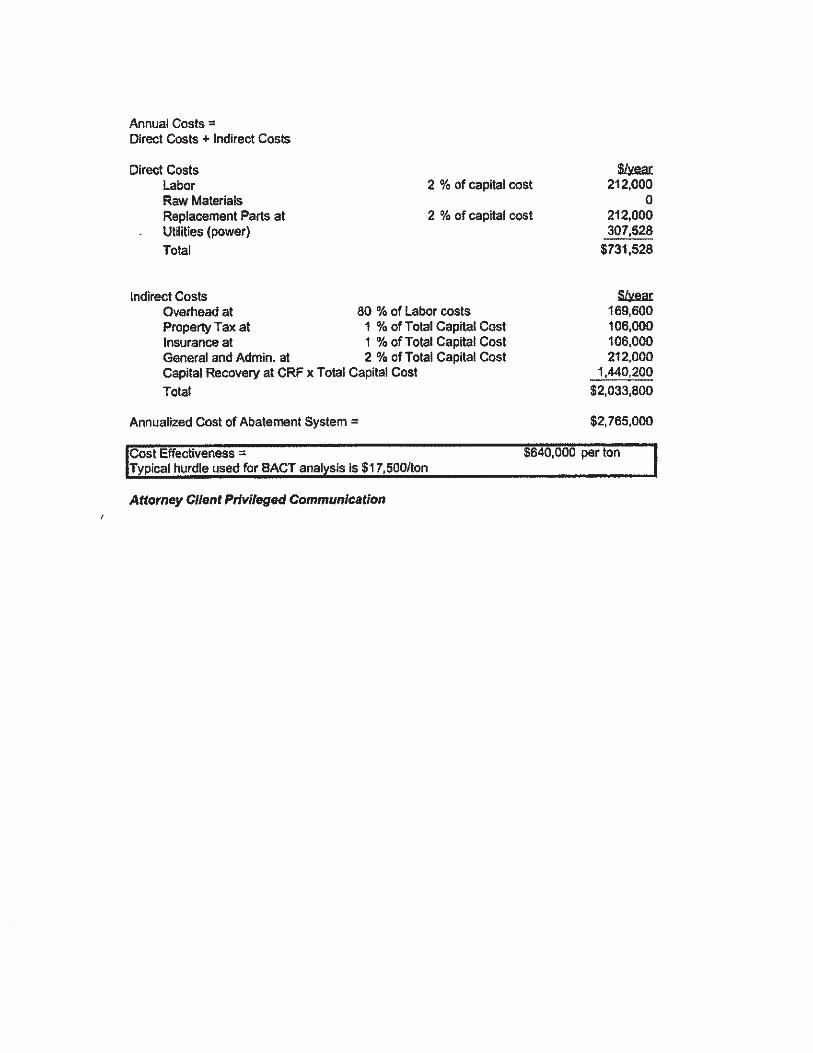


Tesoro Martinez Refinery
Flare Minimization Plan - 2018 Update
0.000
1.000
2.000
3.000
4.000
5.000
6.000
7.000
8.000
9.000
10.000
2001 2002 2003 2004 2005 2006 2007 2008 2009 2010 2011 2012 2013 2014 2015 2016 2017 mid-2018
Em
issio
ns (
ton
s/d
ay,
an
nu
al
av
erag
e)
YEAR
TOTAL FLARE EMISSIONS
NMHC
SO2
METHANE

Tesoro Martinez Refinery
Flare Minimization Plan - 2018 Update
0
1
2
3
4
5
6
7
8
9
2001 2002 2003 2004 2005 2006 2007 2008 2009 2010 2011 2012 2013 2014 2015 2016 2017 YTD2018
Ven
t G
as V
olu
me
(MM
SC
FD
, an
nu
al av
erag
e)
YEAR
Total Flare Vent Gas