Embed Size (px)
Citation preview
EUGENE A. FREKKO
TERRIER/TARTAR: DEMONSTRATION OF AN/SYS-l INTEGRATED AUTOMATIC DETECTION AND TRACKING SYSTEM
Following the invention by APL of the automatic detection and tracking system, tests were performed that used land-based and shipboard radars to assess the effectiveness of its radar video converters and tracking system. These tests also provided the basic information needed to adapt the system so it would integrate data from three radars into one track file and provide the necessary interface to other ship systems. This article describes both the land-based testing at APL and shipboard testing as part of an ongoing ship modernization program for destroyers. The modernization program will permit maximum use of the inherent capability of existing (or modified) rotating-antenna radars and associated equipment.
INTRODUCTION The Integrated Automatic Detection and Tracking
System designated AN/ SYS-l was developed by APL for the U.S. Navy as part of the Guided Missile Destroyer (DOG) Modernization Program. The system was designed primarily to improve a DOG's capability to detect and track large numbers of air targets and to provide more accurate designation data for the missile and gunfire control radars. In addition, surface target tracks can be maintained. Formerly, tracking was accomplished by manual plotting techniques.
SYS-l provides enhanced capabilities in realistic battle environments where electronic countermeasures, poor weather, or surrounding land masses reduce radar effectiveness. The combined data collected from three mutually supportive radars allow SYS-l to accommodate a large number of targets with the accurate and rapid response required to counter the magnitude of the current threat.
SYS-I SYSTEM DESCRIPTION SYS-l is a new system concept that incorporates
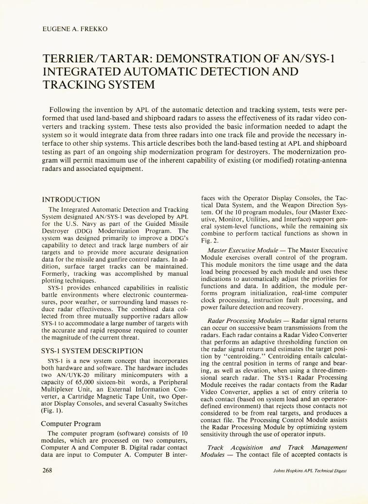
both hardware and software. The hardware includes two AN/ UYK-20 military minicomputers with a capacity of 65,000 sixteen-bit words, a Peripheral Multiplexer Unit, an External Information Converter, a Cartridge Magnetic Tape Unit, two Operator Display Consoles, and several Casualty Switches (Fig. 1).
Computer Program The computer program (software) consists of 10
modules, which are processed on two computers, Computer A and Computer B. Digital radar contact data are input to Computer A. Computer B inter-
268
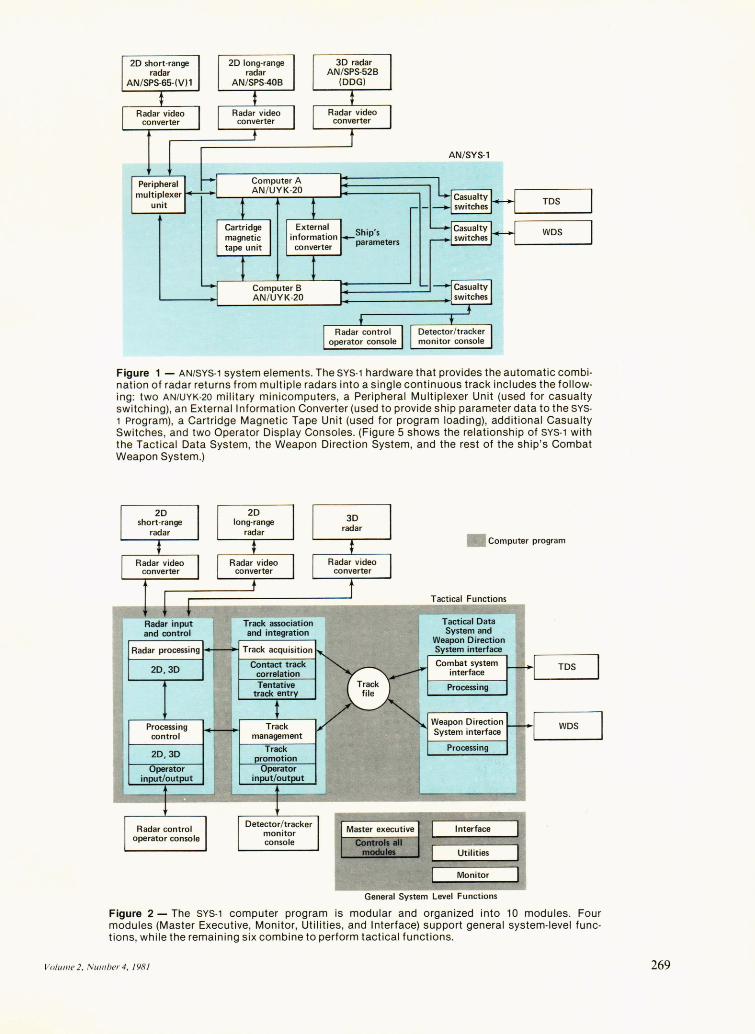
faces with the Operator Display Consoles, the Tactical Data System, and the Weapon Direction System. Of the 10 program modules, four (Master Executive, Monitor, Utilities, and Interface) support general system-level functions, while the remaining six combine to perform tactical functions as shown in Fig. 2.
Master Executive Module - The Master Executive Module exercises overall control of the program. This module monitors the time usage and the data load being processed by each module and uses these indications to automatically adjust the priorities for functions and data. In addition, the module performs program initialization, real-time computer clock processing, instruction fault processing, and power failure detection and recovery.
Radar Processing Modules - Radar signal returns can occur on successive beam transmissions from the radars. Each radar contains a Radar Video Converter that performs an adaptive thresholding function on the radar signal return and estimates the target position by "centroiding." Centroiding entails calculating the central position in terms of range and bearing, as well as elevation, when using a three-dimensional search radar. The SYS-l Radar Processing Module receives the radar contacts from the Radar Video Converter, applies a set of entry criteria to each contact (based on system load and an operatordefined environment) that rejects those contacts not considered to be from real targets, and produces a contact file. The Processing Control Module assists the Radar Processing Module by optimizing system sensitivity through the use of operator inputs.
Track Acquisition and Track Management Modules - The contact file of accepted contacts is
Johns Hopkins APL Technical Digest
Ship's parameters
AN/SYS-l
TDS
WDS
Figure 1 - AN/SYS-1 system elements. The SYS-1 hardware that provides the automatic combination of radar returns from multiple radars into a single continuous track includes the following: two AN/UYK-20 military minicomputers, a Peripheral Multiplexer Unit (used for casualty switching), an External Information Converter (used to provide ship parameter data to the SYS-1 program), a Cartridge Magnetic Tape Unit (used for program loading), additional Casualty Switches, and two Operator Display Consoles. (Figure 5 shows the relationship of SYS-1 with the Tact ical Data System, the Weapon Direction System, and the rest of the ship 's Combat Weapon System.)
2D,3D
Processing control management
• Computer program
Tactical Functions
Tactical Data System and
Weapon Direction System interface
Combat system interface
Processing
Weapon Direction System interface
Processing
Interface
Utilities
Monitor
General System Level Functions
TDS
Figure 2 - The SYS-1 computer program is modular and organized into 10 modules. Four modules (Master Executive, Monitor, Utilities, and Interface) support general system-level functions, while the remaining six combine to perform tactical functions.
Volullle2, N Ulll ber 4, 1981 269
passed to the Track Acquisition Module, which develops a single, unduplicated track file by updating old tracks, by initiating new tracks, and by resolving any track conflicts that may occur. The Track Management Module operates on the track file by evaluating tracks automatically and assigning quality levels to the tracks based on the probability that a given track is valid. A file of track quality computations is maintained for each radar. These computations are combined to form a total track quality number for use in the assignment of track quality levels. The Track Management Module must also handle actions initiated by an operator who continually monitors the tracking output of the system and has the option of making manual entries based on his judgment.
Processing Control Module - The work of the three modules described above is regulated by the Processing Control Module. With the assistance of the operator, it defines the nature and severity of the electromagnetic noise present in the environment, regulates the sensitivity of the system, and acts to prevent overload.
Combat System Interface and Weapon System Interface Modules - The two remaining modules, the Combat System Interface Module and the Weapon System Interface Module, provide interfaces to the Tactical Data System and the Weapon Direction System. The Combat System Interface Module is responsible for supplying the track information required by the Tactical Data System. The Weapon System Interface Module responds to requests from the Weapon Direction System for the track data on targets designated for engagement.
Casualty Operation If enemy action or system malfunction causes a
failure in one of the two computers, SYS-l continues to operate, but with a degraded capability. This is termed "Casualty Operation." If a failure occurs, the computer operating at that moment senses a loss of communication with the other computer. The operating computer then initiates the loading of a reduced-capability "casualty" program from the. Program Loading Device (Cartridge Magnetic Tape Unit). This program is then re-initialized in a Casualty Mode, and selected track data existing prior to the casualty are maintained. While the system track capacity is reduced, all essential functions are performed by the single operating computer.
In Casualty Operations, the Peripheral Multiplexer Unit allows SYS-I to automatically switch both the two-dimensional short-range search radar and the two-dimensional long-range search radar to the operational computer. The casualty switching of the three-dimensional radar data is accommodated by selecting one of two separate links to SYS-l. Switching is also provided for the interfaces to the Tactical Data System, Weapon Direction System, and the
270
Operator Display Consoles. The External Information Converter provides time of day and ship pitch, roll, heading, and speed to both computers during normal operation. It continues to provide these data to the remaining computer during Casualty Operation.
TEST AND EV ALUA TION PROCESS After developmental testing by APL, SYS-l went
through two Navy-specified phases of testing in preparation for introduction into the Fleet: Technical Evaluation (TECHEVAL), followed by Operational Evaluation (OPEVAL). The two evaluations are initiated after the preliminary development has been completed and a prototype model has been constructed. The general goal of the Technical Evaluation phase is to evaluate the soundness of the concept; i.e., does the system appear to be capable of performing to its design specifications? The Operational Evaluation involves testing by Navy personnel to see if the system is effective in actual use.
Developmental Testing The experimental version of the system was tested
on board a guided missile destroyer, USS SOMERS (DDG-34), in 1973. The results of the tests confirmed for the first time the ability of the system to automatically track large numbers of aircraft in an at-sea environment without creating an unacceptable number of false tracks. However, these initial at-sea tests were conducted with a single radar input from either a two-dimensional long-range or a three-dimensional search radar operating independently.
The development and subsequent testing of the concept of integrating radar data from more than one radar followed the initial tests. This integrated capability was introduced in the engineering development model of SYS-l. Using inputs from three search radars (two-dimensional long-range, two-dimensional short-range, and three-dimensional), a composite air picture was achieved.
Technical Evaluation After USS TOWERS (DDG-9) (Fig. 3) was selected
to participate in the at-sea testing of SYS-l , detailed planning for installation of the prototype hardware was undertaken. This test phase was conducted under the sponsorship of the Navy developing agency, the Naval Sea Systems Command. Installation began in September 1977. It required the removal of two existing radars and their replacement with prototypes of the two-dimensional long-range, two-dimensional short-range, and three-dimensional radars that were developed as part of the integrated sensor suite (Fig. 4). The prototype radars were modified versions of the existing radars with Radar Video Converters and digital interfaces to the SYS-l computers. The advantage of this installation was that it required only a minimum number of alterations to the Combat Information Center already in use. Figure 5 shows how the SYS-l subsystem is functionally located in rela-
Johns Hopkins APL Technical Digest
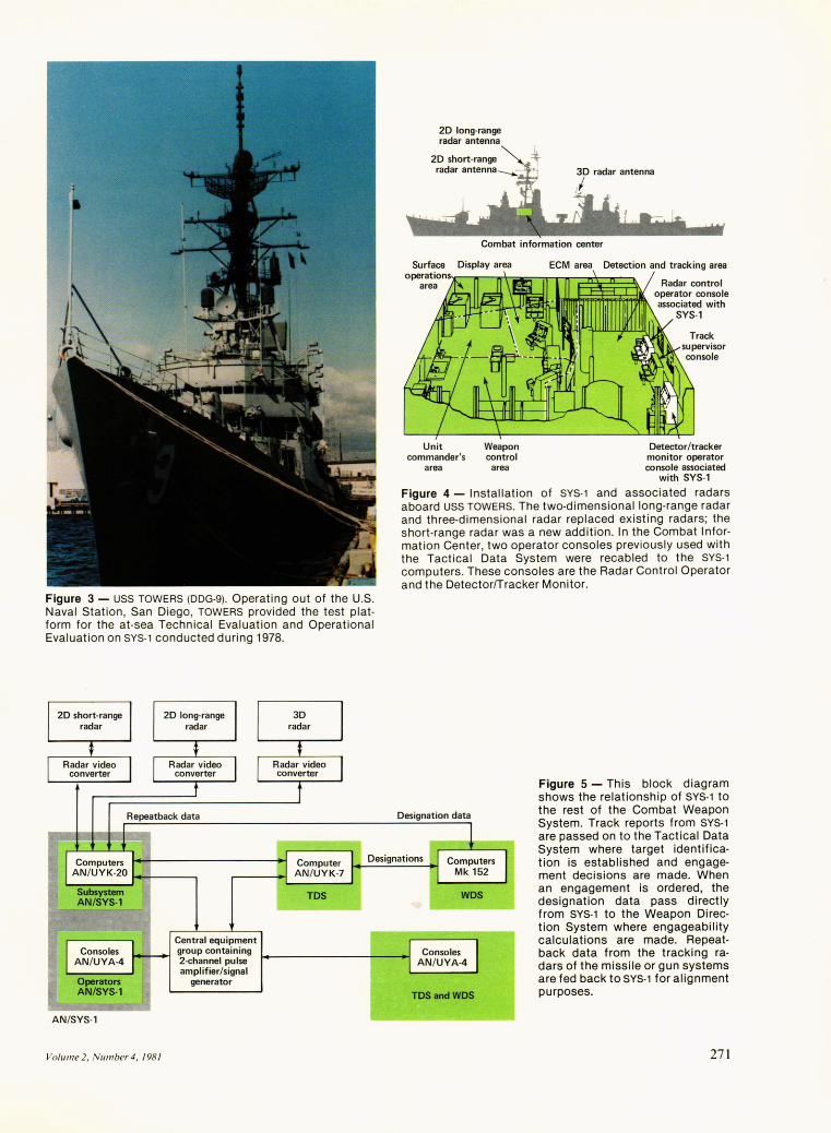
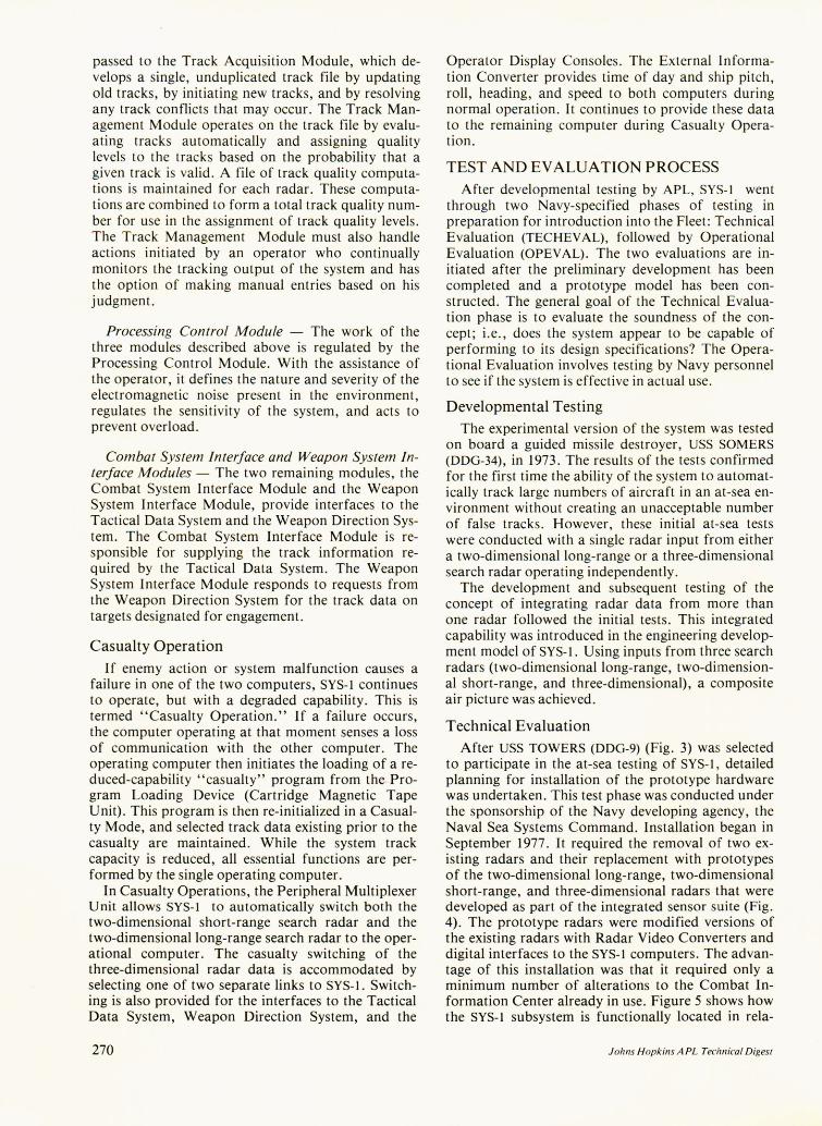
Figure 3 - USS TOWERS (ooG-g)_ Operating out of the U.S. Naval Station, San Diego, TOWERS provided the test platform for the at-sea Technical Evaluation and Operational Evaluation on SYS-1 conducted during 1978.
Repeatback data
2D long-range radar antenna
Combat information center
Display area ECM area Detection and tracking area
Unit Weapon Detector/tracker commander's control monitor operator
area area console associated with SYS-,
Figure 4 - Installation of SYS-1 and associated radars aboard USS TOWERS. The two-dimensional long-range radar and three-dimensional radar replaced existing radars; the short-range radar was a new addition. In the Combat Information Center, two operator consoles previously used with the Tactical Data System were recabled to the SYS-1 computers. These consoles are the Radar Control Operator and the Detector/Tracker Monitor.
Designation data
Designations
Figure 5 - This block diagram shows the relationship of SYS-1 to the rest of the Combat Weapon System. Track reports from SYS-1 are passed on to the Tactical Data System where target identification is established and engagement decisions are made. When an engagement is ordered, the designation data pass directly from SYS-1 to the Weapon Direction System where engageability calculations are made. Repeatback data from the tracking radars of the missile or gun systems are fed back to SYS-1 for alignment purposes_
AN/SYS-'
Volume 2, Number 4, 198 1
Central equipment group containing 2-channel pulse amplifier/signal
generator
TDSandWDS
271
tion to the search radars and users of the automatic track report data (position and velocity).
The specific objectives of the Technical Evaluation were
1. To demonstrate that the engineering design and development process was complete with minimal design risks;
2. To ensure that the system met specifications; 3. To estimate the system's military effectiveness
when introduced. The Technical Evaluation test program began with
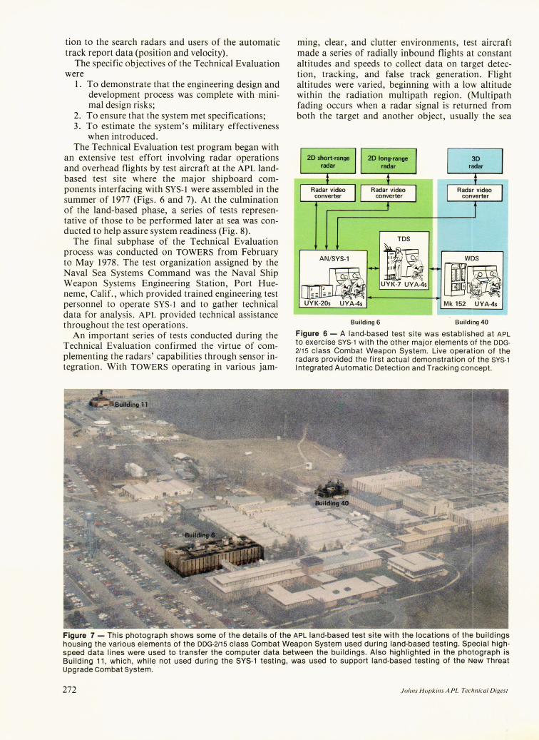
an extensive test effort involving radar operations and overhead flights by test aircraft at the APL landbased test site where the major shipboard components interfacing with SYS-l were assembled in the summer of 1977 (Figs. 6 and 7). At the culmination of the land-based phase, a series of tests representative of those to be performed later at sea was conducted to help assure system readiness (Fig. 8).
The final subphase of the Technical Evaluation process was conducted on TOWERS from February to May 1978. The test organization assigned by the Naval Sea Systems Command was the Naval Ship Weapon Systems Engineering Station, Port Hueneme, Calif., which provided trained engineering test personnel to operate SYS-l and to gather technical data for analysis. APL provided technical assistance throughout the test operations.
An important series of tests conducted during the Technical Evaluation confirmed the virtue of complementing the radars' capabilities through sensor integration. With TOWERS operating in various jam-
ming, clear, and clutter environments, test aircraft made a series of radially inbound flights at constant altitudes and speeds to collect data on target detection, tracking, and false track generation. Flight altitudes were varied, beginning with a low altitude within the radiation multipath region. (Multipath fading occurs when a radar signal is returned from both the target and another object, usually the sea
TDS
ANtSY:-' _ MI ~W~S" .. d UYK7 UYA4, ~~ UYK-20s UYA-4s Mk 152 UYA-4s
Building 6 Building 40
Figure 6 - A land-based test site was established at APL to exercise SYS-1 with the other major elements of the DDG-2/15 class Combat Weapon System. Live operation of the radars provided the first actual demonstration of the SYS-1 I ntegrated Automatic Detection and Tracking concept.
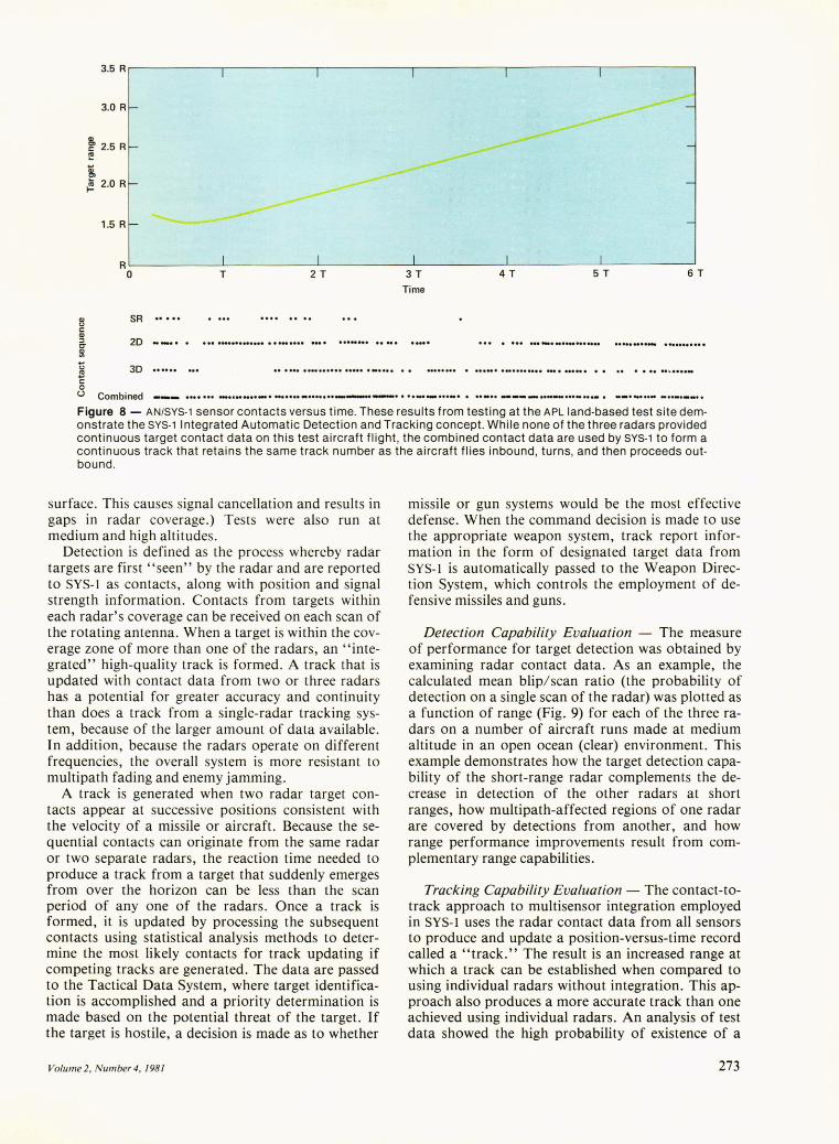
Figure 7 - This photograph shows some of the details of the APL land-based test site with the locations of the buildings housing the various elements of the DDG-2/15 class Combat Weapon System used during land-based testing. Special highspeed data lines were used to transfer the computer data between the buildings. Also highlighted in the photograph is Building 11 , which , while not used during the SYS-1 testing, was used to support land-based testing of the New Threat upgrade combat system.
272 Johns Hopkins A PL Technical Digest
3.5 R
3.0 R
Q)
~ 2.5 R ~ ... Q) Cl
~ 2.0 R
1.5 R
R
Q) t.l c: Q) :::l C' ~ ... t.l
~ c: 0
0 T 2 T
SR
2D
3D
3T
Time
4T 5T 6T
... . ...... --.............. . ..................... .
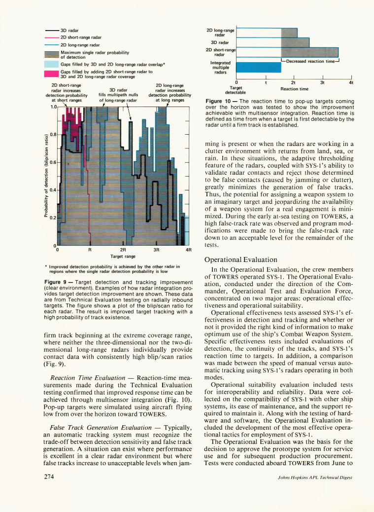
U Combined --- ............................. -................... .-... ....... -.- ....................................... -_ ................... . Figure 8 - AN/SYS-1 sensor contacts versus time. These results from testing at the APL land-based test site demonstrate the SYS-1 Integrated Automatic Detection and Tracking concept. While none of the three radars provided continuous target contact data on this test aircraft flight, the combined contact data are used by SYS-1 to form a continuous track that retains the same track number as the aircraft flies inbound, turns, and then proceeds outbound.
surface. This causes signal cancellation and results in gaps in radar coverage.) Tests were also run at medium and high altitudes.
Detection is defined as the process whereby radar targets are first "seen" by the radar and are reported to SYS-l as contacts, along with position and signal strength information. Contacts from targets within each radar's coverage can be received on each scan of the rotating antenna. When a target is within the coverage zone of more than one of the radars, an "integrated" high-quality track is formed. A track that is updated with contact data from two or three radars has a potential for greater accuracy and continuity than does a track from a single-radar tracking system, because of the larger amount of data available. In addition, because the radars operate on different frequencies, the overall system is more resistant to multipath fading and enemy jamming.
A track is generated when two radar target contacts appear at successive positions consistent with the velocity of a missile or aircraft. Because the sequential contacts can originate from the same radar or two separate radars, the reaction time needed to produce a track from a target that suddenly emerges from over the horizon can be less than the scan period of anyone of the radars. Once a track is formed, it is updated by processing the subsequent contacts using statistical analysis methods to determine the most likely contacts for track updating if competing tracks are generated. The data are passed to the Tactical Data System, where target identification is accomplished and a priority determination is made based on the potential threat of the target. If the target is hostile, a decision is made as to whether
Volume 2, Number 4, 1981
missile or gun systems would be the most effective defense. When the command decision is made to use the appropriate weapon system, track report information in the form of designated target data from SYS-l is automatically passed to the Weapon Direction System, which controls the employment of defensive missiles and guns.
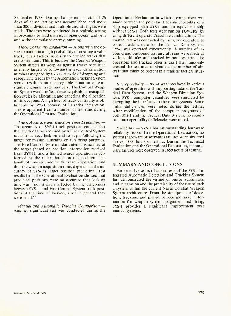
Detection Capability Evaluation - The measure of performance for target detection was obtained by examining radar contact data. As an example, the calculated mean blip/scan ratio (the probability of detection on a single scan of the radar) was plotted as a function of range (Fig. 9) for each of the three radars on a number of aircraft runs made at medium altitude in an open ocean (clear) environment. This example demonstrates how the target detection capability of the short-range radar complements the decrease in detection of the other radars at short ranges, how multipath-affected regions of one radar are covered by detections from another, and how range performance improvements result from complementary range capabilities.
Tracking Capability Evaluation - The contact-totrack approach to multisensor integration employed in SYS-l uses the radar contact data from all sensors to produce and update a position-versus-time record called a "track." The result is an increased range at which a track can be established when compared to using individual radars without integration. This approach also produces a more accurate track than one achieved using individual radars. An analysis of test data showed the high probability of existence of a
273
--30 radar
-- 20 short-range radar
-- 20 long-range radar
- Maximum single radar probability === of detection
Gaps filled by 30 and 20 long-range radar overlap* _Gaps filled by adding 20 short-range radar to 30 and 20 long-range radar coverage
20 short-range radar increases
detection probability at short ranges
20 long-range radar increases
detection probability
c:: CtI
~ Ci
1.Ur-~~;;-:;--.::
~ 0.6 c:: o 'oJ (.J CI)
~ "0
'0 0.4
~ :0
. ~ o
a: 0.2
o o R 2R
Target range
at I
3R
* Improved detection probability is achieved by the other radar in regions where the single radar detection probability is low
4R
Figure 9 - Target detection and tracking improvement (clear environment). Examples of how radar integration provides target detection improvement are shown. These data are from Technical Evaluation testing on radially inbound targets. The figure shows a plot of the blip/scan ratio for each radar. The result is improved target tracking with a high probability of track existence.
firm track beginning at the extreme coverage range, where neither the three-dimensional nor the two-dimensional long-range radars individually provide contact data with consistently high blip/ scan ratios (Fig. 9).
Reaction Time Evaluation - Reaction-time measurements made during the Technical Evaluation testing confirmed that improved response time can be achieved through multisensor integration (Fig. 10). Pop-up targets were simulated using aircraft flying low from over the horizon toward TOWERS.
False Track Generation Evaluation - Typically, an automatic tracking system must recognize the trade-off between detection sensitivity and false track generation. A situation can exist where performance is excellent in a clear radar environment but where false tracks increase to unacceptable levels when jam-
274
20 long-range radar
30 radar
20 short-ran radar
Integrated multiple radars
o Target
detectable
2t Reaction time
3t 4t
Figure 10 - The reaction time to pop-up targets coming over the horizon was tested to show the improvement achievable with multisensor integration. React ion time is defined as time from when a target is first detectable by the radar until a firm track is established.
ming is present or when the radars are working in a clutter environment with returns from land, sea, or rain. In these situations, the adaptive thresholding feature of the radars, coupled with SYS-I 's ability to validate radar contacts and reject those determined to be false contacts (caused by jamming or clutter), greatly minimizes the generation of false tracks. Thus, the potential for assigning a weapon system to an imaginary target and jeopardizing the availability of a weapon system for a real engagement is minimized. During the early at-sea testing on TOWERS, a high false-track rate was observed and program modifications were made to bring the false-t rack rate down to an acceptable level for the remainder of the tests.
Operational Evaluation In the Operational Evaluation, the crew members
of TOWERS operated SYS-I. The Operational Evaluation, conducted under the direction of the Commander, Operational Test and Evaluation Force, concentrated on two major areas: operational effectiveness and operational suitability.
Operational effectiveness tests assessed SYS-I 's effectiveness in detection and tracking and whether or not it provided the right kind of information to make optimum use of the ship's Combat Weapon System. Specific effectiveness tests included evaluations of detection, the continuity of the tracks, and SYS-I's reaction time to targets. In addition, a comparison was made between the speed of manual versus automatic tracking using SYS-I 's radars operating in both modes.
Operational suitability evaluation included tests for interoperability and reliability. Data were collected on the compatibility of SYS-l with other ship systems, its ease of maintenance, and the support required to maintain it. Along with the testing of hardware and software, the Operational Evaluation included the development of the most effective operational tactics for employment of SYS-I.
The Operational Evaluation was the basis for the decision to approve the prototype system for service use and for subsequent production procurement. Tests were conducted aboard TOWERS from June to
Johns Hopkins APL Technical Digest
September 1978. During that period, a total of 26 days of at-sea testing was accomplished and more than 300 individual and multiple aircraft flights were made. The tests were conducted in a realistic setting in proximity to land masses, in open ocean, and with and without simulated enemy jamming.
Track Continuity Evauation - Along with the desire to maintain a high probability of creating a valid track, it is a tactical necessity to provide tracks that are continuous. This is because the Combat Weapon System directs its weapons against tracks identified as enemy targets by following the track identification numbers assigned by SYS-l. A cycle of dropping and reacquiring tracks by the Automatic Tracking System would result in an unacceptable situation of constantly changing track numbers. The Combat Weapon System would reflect these acquisition/ reacquisition cycles by allocating and canceling the allocation of its weapons. A high level of track continuity is obtainable by SYS-l because of its radar integration. This is apparent from a number of test runs during the Operational Test and Evaluation.
Track Accuracy and Reaction Time Evaluation -The accuracy of SYS-l track positions could affect the length of time required by a Fire Control System radar to achieve lock-on and to begin following the target for missile launching or gun firing purposes. The Fire Control System radar antenna is pointed at the target (based on position information received from SYS-l), and a limited search operation is performed by the radar, based on this position. The length of time required for this search operation, and thus the weapon acquisition time, depends on the accuracy of SYS-l's target position prediction. Test results from the Operational Evaluation showed that predicted positions were so accurate that lock-on time was "not strongly affected by the differences between SYS-l and Fire Control System track positions at the time of lock-on, since in general they were small."
Manual and Automatic Tracking Comparison -Another significant test was conducted during the
Volume 2, N umber 4, 1981
Operational Evaluation in which a comparison was made between the potential tracking capability of a ship equipped with SYS-l and an equivalent ship without SYS-l. Both tests were run on TOWERS by using different operator/machine combinations. The manual test was conducted by using two operators to collect tracking data for the Tactical Data System. SYS-l was operated concurrently. A number of inbound and outbound test aircraft runs were made at various altitudes and tracked by both systems. The operators also tracked other aircraft that randomly crossed the test area to simulate the number of aircraft that might be present in a realistic tactical situation.
Interoperability - SYS-l was interfaced in various modes of operation with supporting radars, the Tactical Data System, and the Weapon Direction System. SYS-l computer casualties were simulated by disrupting the interfaces to the other systems. Some initial deficiencies were noted during the testing. After modification of the computer programs of both SYS-l and the Tactical Data System, no significant interoperability deficiencies were noted.
Reliability - SYS-l has an outstanding hardware reliability record. In the Operational Evaluation, no system (hardware or software) failures were observed in over 1000 hours of testing. During the Technical Evaluation and the Operational Evaluation, no hardware failures were observed in 1659 hours of testing.
SUMMARY AND CONCLUSIONS An extensive series of at-sea tests of the SYS-l In
tegrated Automatic Detection and Tracking System has demonstrated the virtues of sensor automation and integration and the practicality of the use of such a system within the current Naval Combat Weapon System architecture. From the standpoints of detection, tracking, and providing accurate target information for weapon system assignment and firing, SYS-l provides a significant improvement over manual systems.
275