Embed Size (px)
Citation preview

M609155-01 Rev H www.programmablepower.com
TerraSAS Software
Installation and User Manual
Programmable Power Solutions

i

ii
About AMETEK
AMETEK Programmable Power, Inc., a Division of AMETEK, Inc., is a global leader in the design and manufacture of precision, programmable power supplies for R&D, test and measurement, process control, power bus simulation and power conditioning applications across diverse
industrial segments. From bench top supplies to rack-mounted industrial power subsystems, AMETEK Programmable Power is the proud manufacturer of Elgar, Sorensen, California Instruments and Power Ten brand power supplies.
AMETEK, Inc. is a leading global manufacturer of electronic instruments and electromechanical devices with annualized sales of $2.5 billion. The Company has over 11,000 colleagues working at more than 80 manufacturing facilities and more than 80 sales and service centers in the United States and around the world.
Trademarks
AMETEK is a registered trademark of AMETEK, Inc. Other trademarks, registered trademarks, and product names are the property of their respective owners and are used herein for identification purposes only.
Notice of Copyright
Terrestrial Solar Array Simulator, Operation and Maintenance Manual © 2014 AMETEK Programmable Power, Inc. All rights reserved.
Exclusion for Documentation
UNLESS SPECIFICALLY AGREED TO IN WRITING, AMETEK PROGRAMMABLE POWER, INC. (“AMETEK”):
(a) MAKES NO WARRANTY AS TO THE ACCURACY, SUFFICIENCY OR SUITABILITY OF ANY TECHNICAL OR OTHER INFORMATION PROVIDED IN ITS MANUALS OR OTHER DOCUMENTATION.
(b) ASSUMES NO RESPONSIBILITY OR LIABILITY FOR LOSSES, DAMAGES, COSTS OR EXPENSES, WHETHER SPECIAL, DIRECT, INDIRECT, CONSEQUENTIAL OR INCIDENTAL, WHICH MIGHT ARISE OUT OF THE USE OF SUCH INFORMATION. THE USE OF ANY SUCH INFORMATION WILL BE ENTIRELY AT THE USER’S RISK, AND
(c) REMINDS YOU THAT IF THIS MANUAL IS IN ANY LANGUAGE OTHER THAN ENGLISH, ALTHOUGH STEPS HAVE BEEN TAKEN TO MAINTAIN THE ACCURACY OF THE TRANSLATION, THE ACCURACY CANNOT BE GUARANTEED. APPROVED AMETEK CONTENT IS CONTAINED WITH THE ENGLISH LANGUAGE VERSION, WHICH IS POSTED AT WWW.PROGRAMMABLEPOWER.COM.
Date and Revision
Feb 17, 2014 Revision H - covers TerraSAS software revision 2.0.X.X
Part Number
M609155-01
Contact Information
Telephone: 800 733 5427 (toll free in North America)
858 450 0085 (direct) Fax: 858 458 0267 Email: [email protected] [email protected] Web: www.programmablepower.com

iii

1
TABLE OF CONTENTS SOFTWARE INSTALLATION GUIDE .................................................................. 7
Computer requirements ........................................................................................................ 7 Supported operating systems ............................................................................................... 7 Minimum hardware configuration .......................................................................................... 7
Installation under Windows 7 ................................................................................................ 7 Setting the computer name and description .......................................................................... 7 Creating a user account........................................................................................................ 7 Deleting the default account ................................................................................................. 7 Network configuration for on-line desktop systems................................................................ 8 Network configuration for off-line desktop systems................................................................ 8 Network configuration for off-line, single channel desktop systems ....................................... 8 Network configuration for factory- configured rack systems ................................................... 8 Software installation ............................................................................................................. 8 Activating the DHCP server .................................................................................................. 8
Running TerraSAS for the first time.................................................................................... 10 Creating system configuration tables .................................................................................. 10 Saving customized system settings .................................................................................... 12 Folders and example files ................................................................................................... 12 Display resolution ............................................................................................................... 13
SOFTWARE USER GUIDE ................................................................................ 15
Basic concepts .................................................................................................................... 15 Overview ............................................................................................................................ 15 DEMO MODE operation ..................................................................................................... 16 Turning the system on and off ............................................................................................ 17 Recommended system turn on sequence ........................................................................... 17 Recommended system turn off sequence ........................................................................... 17 Graphic chart features in the Photovoltaic simulation tab .................................................... 17 Graphic chart features in the System control tab ................................................................. 17
Main menu items description .............................................................................................. 18 File > Load Test Session .................................................................................................... 18 File > Save Test Session .................................................................................................... 18 Photovoltaic curve > Load (SNL) ........................................................................................ 18 Photovoltaic curve > Import (SAM) ..................................................................................... 18 Photovoltaic curve > Create (SNL) ...................................................................................... 19 Photovoltaic curve > EN 50530:2010 > Create / Update Curve ........................................... 19 Photovoltaic curve > EN50530:2010 > Edit coefficients ....................................................... 19 Photovoltaic curve > Remove > All ..................................................................................... 19 Photovoltaic curve > Remove > Selected ............................................................................ 19 Irradiance profile > Load ..................................................................................................... 20 Irradiance profile > Remove > All ........................................................................................ 20 Irradiance profile > Remove > Selected .............................................................................. 20 Irradiance profile > Create .................................................................................................. 20 Array > Add ........................................................................................................................ 20 Array > Remove > All ......................................................................................................... 20 Array > Remove > Selected ................................................................................................ 20 System > Configure > PV Simulators .................................................................................. 20 System > Configure > Settings ........................................................................................... 21 System > Configure > Import inverter data .......................................................................... 22 System > Reset .................................................................................................................. 24 System > Debug > Show SCPI traffic ................................................................................. 24 System > Debug > Show timing .......................................................................................... 24

2
System > Debug > Show errors .......................................................................................... 25 System > Debug > Show External inputs ............................................................................ 25 System > Data logging ....................................................................................................... 26 System > Channels grouping setup .................................................................................... 26 System > I/L Energy monitor .............................................................................................. 27 Measure > Time > MPPT Recovery .................................................................................... 28 Measure > Energy .............................................................................................................. 29
User interface details ........................................................................................................... 30 Output channel tile description ............................................................................................ 30 Channel faults and protections ........................................................................................... 31 Channels grouping ............................................................................................................. 32 Channels programming ...................................................................................................... 32 All channels tile description ................................................................................................ 33
High Power Systems support.............................................................................................. 34 Main AC circuit breaker on-off control ................................................................................. 34 Warnings and protections ................................................................................................... 35
Advanced programming ...................................................................................................... 36 Executing a static simulation............................................................................................... 36 Soft-starting the inverter under test ..................................................................................... 36 Creating and managing EN 50530 test sessions ................................................................. 37 Maximizing measurement accuracy during fast profiles ....................................................... 38 Creating an irradiance / temperature profile ........................................................................ 41 Executing a dynamic simulation .......................................................................................... 43 Executing a dynamic simulation controlled by analog signals .............................................. 45 Preparing a static array simulation ...................................................................................... 46 Adding and populating an array .......................................................................................... 46 Programming an array ........................................................................................................ 47 Executing a static array simulation ...................................................................................... 50
Operation in Power Supply mode ....................................................................................... 51 Constant Voltage (CV) mode .............................................................................................. 51 Constant Current (CC) mode .............................................................................................. 52
Remote interface operation ................................................................................................. 53 Using the SCPI Test utility .................................................................................................. 53 Sending and receiving commands ...................................................................................... 53 Connecting to TerraSAS using third party applications ........................................................ 54
Release notes ...................................................................................................................... 55 TerraSAS 1.7.5.0 changes and improvements .................................................................... 55 TerraSAS 1.7.8.0 changes and improvements .................................................................... 55 TerraSAS 2.0.0.0 changes and improvements .................................................................... 55 Features for future release ................................................................................................. 55
Reporting software bugs ..................................................................................................... 56 File formats .......................................................................................................................... 58
Curves ............................................................................................................................... 58 Irradiance profiles ............................................................................................................... 58 Irradiance profile tables ...................................................................................................... 59 Session files ....................................................................................................................... 59 Data logging files ................................................................................................................ 59
TERRASAS SCPI COMMANDS REFERENCE ................................................. 61
Overview .............................................................................................................................. 61 Release 2.X SCPI commands update .................................................................................. 62
Backward compatibility with TerraSAS 1.X SCPI scripts ..................................................... 64 IEEE-488.2 commands and queries .................................................................................... 65
*CLS .................................................................................................................................. 65 *ESR? ................................................................................................................................ 65 *IDN? ................................................................................................................................. 66

3
*OPC.................................................................................................................................. 66 *OPC?................................................................................................................................ 66 *RST .................................................................................................................................. 66 *WAI .................................................................................................................................. 66
SYSTem commands and queries ........................................................................................ 67 SYSTem:ERRor[:NEXT]? ................................................................................................... 67 SYSTem:REMote ............................................................................................................... 67 SYSTem:REMote? ............................................................................................................. 67 SYSTem:LOCal .................................................................................................................. 67 SYSTem:CHANnel[:COUNt]? ............................................................................................. 67 SYSTem:CHANnel:SERial? [(@chanlist)] ........................................................................... 67 SYSTem:CHANnel:MAXPower? [(@chanlist)] .................................................................... 68 SYSTem:CHANnel:MAXVoltage? [(@chanlist)] .................................................................. 68 SYSTem:CHANnel:MAXCurrent? [(@chanlist)]................................................................... 68 SYSTem:CHANnel:MAXOVervoltage? [(@chanlist)] ........................................................... 68 SYSTem:CHANnel:MAXOVCurrent? [(@chanlist)].............................................................. 68 SYSTem:VERSion?............................................................................................................ 69 SYSTem:GROup:CATalog? ............................................................................................... 69 SYSTem:GROup:DELEte:ALL ............................................................................................ 69 SYSTem:GROup:DEFine:PARallel <group>, (@chanlist).................................................... 69 SYSTem:GROup:PARallel? <group> .................................................................................. 70 SYSTem:GROup:DEFine:SERies <group>, (@chanlist) ..................................................... 70 SYSTem:GROup:SERies? <group> ................................................................................... 70 SYSTem:GROup:SETup .................................................................................................... 71
CURVe subsystem ............................................................................................................... 72 CURVe:READFile <file name> ........................................................................................... 72 CURVe:VIparms <Voc>, <Isc> ........................................................................................... 72 CURVe:VIparms? ............................................................................................................... 72 CURVe:MPPparms <Vmp>,<Imp>...................................................................................... 72 CURVe:MPPparms?........................................................................................................... 72 CURVe:FORMfactor <form factor> ..................................................................................... 73 CURVe:FORMfactor? ......................................................................................................... 73 CURVe:BETAparms <Beta V>,<Beta P> ............................................................................ 73 CURVe:BETAparms? ......................................................................................................... 73 CURVe:KFactor <voltage>,<irradiance> ............................................................................. 73 CURVe:KFactor?................................................................................................................ 73 CURVe:ADD <name> ......................................................................................................... 74 CURVe:DELEte <name> .................................................................................................... 74 CURVe:CATalog? .............................................................................................................. 74 CURVe:EN50530:MPPparms <Pmp>, <Vmp> .................................................................... 74 CURVe:EN50530:MPPparms? ........................................................................................... 74 CURVe:EN50530:SIMtype {CSI|TF},{STA|DYN} ................................................................. 75 CURVe:EN50530:SIMtype?................................................................................................ 75 CURVe:EN50530:ADD ....................................................................................................... 75
PROFile subsystem ............................................................................................................. 76 PROFile:READFile <file name> .......................................................................................... 76 PROFile:DELEte <name> ................................................................................................... 76 PROFile:CATalog? ............................................................................................................. 76
ARRAy subsystem ............................................................................................................... 77 ARRAy:SIZE <modules>,<strings> ..................................................................................... 77 ARRAy:SIZE? .................................................................................................................... 77 ARRAy:ADD <name> ......................................................................................................... 77 ARRAy:SELect <name> ..................................................................................................... 77 ARRAy:SELect? ................................................................................................................. 77 ARRAy:MODule#:STRing#:CURVe <name> ...................................................................... 78 ARRAy:MODule#:STRing#:CURVe? .................................................................................. 78

4
ARRAy:MODule#:STRing#:PROFile <name> ..................................................................... 78 ARRAy:MODule#:STRing#:PROFile? ................................................................................. 78 ARRAy:MULTiplier <value> ................................................................................................ 79 ARRAy:MULTiplier? ........................................................................................................... 79 ARRAy:DELEte <name> .................................................................................................... 79 ARRAy:CATalog? ............................................................................................................... 79
SOURce subsystem ............................................................................................................. 80 [SOURce:]CURVe <name> [,(@chanlist)] ........................................................................... 80 [SOURce:]CURVe? [(@chanlist)] ........................................................................................ 80 [SOURce:]IRRadiance <irradiance> [,(@chanlist)] .............................................................. 80 [SOURce:]IRRadiance? [(@chanlist)] ................................................................................. 80 [SOURce:]TEMPerature <temperature> [,(@chanlist)] ........................................................ 81 [SOURce:]TEMPerature? [(@chanlist)] ............................................................................... 81 [SOURce:]VOLTage <volts> [,(@chanlist)] ......................................................................... 81 [SOURce:]VOLTage? [(@chanlist)] .................................................................................... 81 [SOURce:]CURRent <amps> [,(@chanlist)] ........................................................................ 82 [SOURce:]CURRent? [(@chanlist)] .................................................................................... 82 [SOURce:]EN50530:VOLTage <volts> [,(@chanlist)] .......................................................... 82 [SOURce:]EN50530:VOLTage? [(@chanlist)] ..................................................................... 82 [SOURce:]EN50530:POWer <watts> [,(@chanlist)] ............................................................ 83 [SOURce:]EN50530:POWer? [(@chanlist)]......................................................................... 83 [SOURce:]EN50530:TECHnology {CSI|TF} [,(@chanlist)] ................................................... 83 [SOURce:]EN50530:TECHnology? [(@chanlist)] ................................................................ 83 [SOURce:]EN50530:SIMtype {STA|DYN} [,(@chanlist)] ...................................................... 84 [SOURce:]EN50530:SIMtype? [(@chanlist)] ....................................................................... 84 [SOURce:]EXECute [,(@chanlist)] ...................................................................................... 84 [SOURce:]PROFile <name> [,(@chanlist)] ......................................................................... 84 [SOURce:]PROFile? [(@chanlist)] ...................................................................................... 85 [SOURce:]PROFile:OFFSet <value> [,(@chanlist)] ............................................................. 85 [SOURce:]PROFile:OFFSet? [(@chanlist)] ......................................................................... 85 [SOURce:]VOLTage:PROTection[:LEVel] <value> [,(@chanlist)] ........................................ 85 [SOURce:]VOLTage:PROTection[:LEVel]? [(@chanlist)] .................................................... 86 [SOURce:]CURRent:PROTection[:LEVel] <value> [,(@chanlist)] ........................................ 86 [SOURce:]CURRent:PROTection[:LEVel]? [(@chanlist)] .................................................... 86 [SOURce:]ARRAy <name> [,(@chanlist)] ........................................................................... 86 [SOURce:]ARRAy? [(@chanlist)] ........................................................................................ 86 SOURce#:ARRAy:MODule#:STRing#:IRRadiance <irradiance> ......................................... 87 SOURce#:ARRAy:MODule#:STRing#:IRRadiance? ........................................................... 87 SOURce#:ARRAy:MODule#:STRing#:TEMPerature <temperature> ................................... 87 SOURce#:ARRAy:MODule#:STRing#:TEMPerature? ......................................................... 87 SOURce#:ARRAy:MODule#:STRing#:DIOde {YES|NO} ..................................................... 88 SOURce#:ARRAy:MODule#:STRing#:DIOde? ................................................................... 88 SOURce#:ARRAy:MODule#:STRing#:RESistance <resistance> ........................................ 88 SOURce#:ARRAy:MODule#:STRing#:RESistance? ........................................................... 88 SOURce#:ARRAy:EXECute ............................................................................................... 89
STATus subsystem.............................................................................................................. 90 STATus:OPERation:CONDition? [(@chanlist)].................................................................... 90
SENSe subsystem ............................................................................................................... 91 SENSe:DLOG:TINTerval <value> ....................................................................................... 91 SENSe:DLOG:TINTerval? .................................................................................................. 91 SENSe:DLOG:NAME <name> ........................................................................................... 91 SENSe:DLOG:NAME? ....................................................................................................... 91 SENSe:DLOG:ENABle [(@chanlist)]................................................................................... 91 SENSe:DLOG:ENABle? [(@chanlist)] ................................................................................. 92 SENSe:DLOG:DATA (numlist) ............................................................................................ 92 SENSe:DLOG:DATA? ........................................................................................................ 92

5
SENSe:PROFile:SPeed <value> [,(@chanlist)] ................................................................... 93 SENSe:PROFile:SPeed? [(@chanlist)] ............................................................................... 93 SENSe:PROFile:LOOP {ON|OFF} [,(@chanlist)] ................................................................ 93 SENSe:PROFile:LOOP? [(@chanlist)] ................................................................................ 93 SENSe:AVERage {OFF|4|8|20|40|80|200|400} [,(@chanlist)] .............................................. 93 SENSe:AVERage? [(@chanlist)] ....................................................................................... 94 SENSe:Pgain <value> [,(@chanlist)] .................................................................................. 94 SENSe:Pgain? [(@chanlist)] ............................................................................................... 94 SENSe:Igain <value> [,(@chanlist)] .................................................................................... 94 SENSe:Igain? [(@chanlist)] ................................................................................................ 94 SENSe:Dgain <value> [,(@chanlist)] .................................................................................. 95 SENSe:Dgain? [(@chanlist)]............................................................................................... 95 SENSe:VPgain <value> [,(@chanlist)] ................................................................................ 95 SENSe:VPgain? [(@chanlist)] ............................................................................................ 95 SENSe:VIgain <value> [,(@chanlist)] ................................................................................. 95 SENSe:VIgain? [(@chanlist)] .............................................................................................. 96 SENSe:VDgain <value> [,(@chanlist)] ................................................................................ 96 SENSe:VDgain? [(@chanlist)] ............................................................................................ 96 SENSe:MODe {PS|PV} [,(@chanlist)] ................................................................................. 96 SENSe:MODe? [(@chanlist)].............................................................................................. 96 SENSe:INLimiter {ON|OFF} [,(@chanlist)] .......................................................................... 97 SENSe:INLimiter? [(@chanlist)] .......................................................................................... 97 SENSe:ILEnergy <energy> [,(@chanlist)] ........................................................................... 97 SENSe:ILEnergy? [(@chanlist)] .......................................................................................... 97 SENSe:DIslope {ON|OFF} [,(@chanlist)] ............................................................................ 97 SENSe:DIslope? [(@chanlist)] ............................................................................................ 98 SENSe:MPPTRecovery:CURVe <name> ........................................................................... 98 SENSe:MPPTRecovery:CURVe? ....................................................................................... 98 SENSe:MPPTRecovery:PROFile <name> .......................................................................... 98 SENSe:MPPTRecovery:PROFile? ...................................................................................... 98 SENSe:MPPTRecovery:TRIGger <leading edge>,<trailing edge> ....................................... 99 SENSe:MPPTRecovery:TRIGger?...................................................................................... 99 SENSe:MPPTRecovery:MAXimum <leading edge>,<trailing edge> .................................... 99 SENSe:MPPTRecovery:MAXimum? ................................................................................... 99 SENSe:MPPTRecovery:VALue <leading edge>,<trailing edge> ......................................... 99 SENSe:MPPTRecovery:VALue? ...................................................................................... 100 SENSe:MPPTRecovery:TOLerance <leading edge>,<trailing edge>................................. 100 SENSe:MPPTRecovery:TOLerance? ............................................................................... 100 SENSe:MPPTRecovery:ENABle [(@chanlist)] .................................................................. 100 SENSe:MPPTRecovery:ENABle? [(@chanlist)] ................................................................ 100 SENSe:ENERgy:RESet [(@chanlist)] ............................................................................... 101
MEASure subsystem ......................................................................................................... 102 MEASure[:SCALar]:CURRent[:DC]? [(@chanlist)] ............................................................ 102 MEASure[:SCALar]:CURRent:AC? [(@chanlist)] .............................................................. 102 MEASure[:SCALar]:VOLTage[:DC]? [(@chanlist)] ............................................................ 102 MEASure[:SCALar]:VOLTage:AC? [(@chanlist)] .............................................................. 102 MEASure[:SCALar]:POWer[:DC]? [(@chanlist)] ................................................................ 102 MEASure[:SCALar]:MPPaccuracy? [(@chanlist)] .............................................................. 103 MEASure[:SCALar]:MPPTRecovery? ............................................................................... 103 MEASure[:SCALar]:ENERgy[:DC]? [(@chanlist)] .............................................................. 103
TRIGger subsystem ........................................................................................................... 104 TRIGger:DLOG[:IMMediate] ............................................................................................. 104 TRIGger[:TRANsient][:IMMediate] [(@chanlist)] ................................................................ 104 TRIGger[:TRANsient][:IMMediate]:PAUse [(@chanlist)] .................................................... 104 TRIGger[:TRANsient][:IMMediate]:RESet [(@chanlist)] ..................................................... 104 TRIGger:MPPTRecovery[:IMMediate] ............................................................................... 105

6
ABORt commands ............................................................................................................. 106 ABORt:DLOG ................................................................................................................... 106 ABORt[:TRANsient] [(@chanlist)] ..................................................................................... 106 ABORt:MPPTRecovery .................................................................................................... 106
OUTPut subsystem ............................................................................................................ 107 OUTPut[:STATe] {ON|OFF} [,(@chanlist)] ........................................................................ 107 OUTPut[:STATe]? [(@chanlist)] ........................................................................................ 107 OUTPut:PROTection:CLEar [(@chanlist)] ......................................................................... 107
Units of Measure ................................................................................................................ 108 Units of Measure .............................................................................................................. 108
SCPI LANGUAGE TUTORIAL ......................................................................... 110
7
Software installation guide
Computer requirements
Supported operating systems
Microsoft Windows XP Service Pack 3 Microsoft Windows 7 (32-bit and 64-bit) Microsoft Windows 8 (32-bit and 64-bit)
Minimum hardware configuration
Intel i3-3220 processor, 3.3 GHz or equivalent 2 GB RAM Intel HD Graphics adapter or equivalent. One Network Interface Card for small systems (less than 5 channels) Two Network Interface Cards for large systems (5 or more channels) Keyboard and pointing device (3-button scrolling mouse highly recommended)
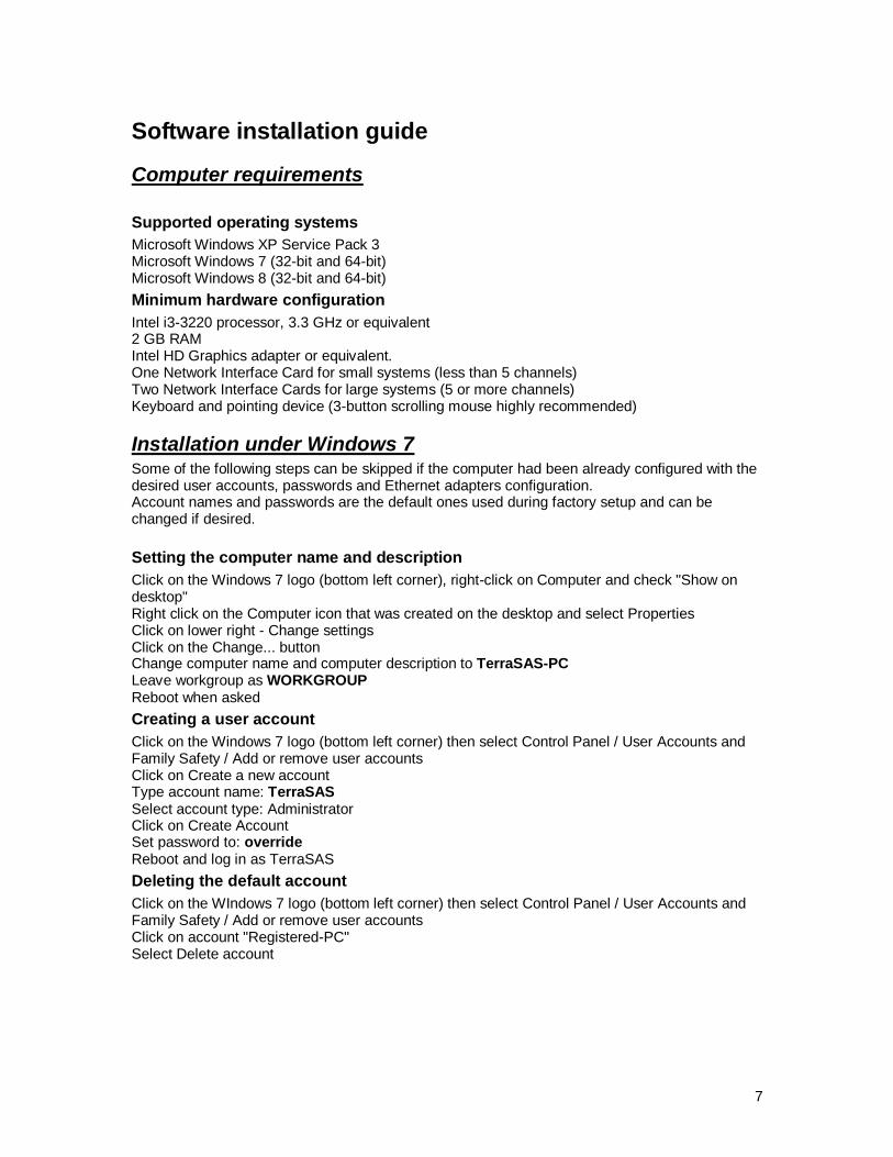
Installation under Windows 7 Some of the following steps can be skipped if the computer had been already configured with the desired user accounts, passwords and Ethernet adapters configuration. Account names and passwords are the default ones used during factory setup and can be changed if desired.
Setting the computer name and description
Click on the Windows 7 logo (bottom left corner), right-click on Computer and check "Show on desktop" Right click on the Computer icon that was created on the desktop and select Properties Click on lower right - Change settings Click on the Change... button Change computer name and computer description to TerraSAS-PC Leave workgroup as WORKGROUP Reboot when asked
Creating a user account
Click on the Windows 7 logo (bottom left corner) then select Control Panel / User Accounts and Family Safety / Add or remove user accounts Click on Create a new account Type account name: TerraSAS Select account type: Administrator Click on Create Account Set password to: override Reboot and log in as TerraSAS
Deleting the default account
Click on the WIndows 7 logo (bottom left corner) then select Control Panel / User Accounts and Family Safety / Add or remove user accounts Click on account "Registered-PC" Select Delete account
8
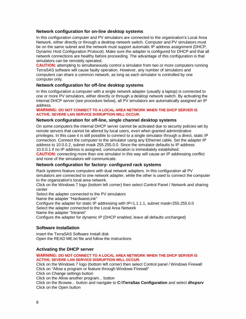
Network configuration for on-line desktop systems
In this configuration computer and PV simulators are connected to the organization’s Local Area Network, either directly or through a desktop network switch. Computer and PV simulators must be on the same subnet and the network must support automatic IP address assignment (DHCP, Dynamic Host Configuration Protocol). Make sure the adapter is configured for DHCP and that all network connections are healthy before proceeding. The advantage of this configuration is that simulators can be remotely operated. CAUTION: attempting to simultaneously control a simulator from two or more computers running TerraSAS software will cause faulty operation. However, any number of simulators and computers can share a common network, as long as each simulator is controlled by one computer only.
Network configuration for off-line desktop systems
In this configuration a computer with a single network adapter (usually a laptop) is connected to one or more PV simulators, either directly or through a desktop network switch. By activating the internal DHCP server (see procedure below), all PV simulators are automatically assigned an IP address. WARNING: DO NOT CONNECT TO A LOCAL AREA NETWORK WHEN THE DHCP SERVER IS
ACTIVE. SEVERE LAN SERVICE DISRUPTION WILL OCCUR.
Network configuration for off-line, single channel desktop systems
On some computers the internal DHCP server cannot be activated due to security policies set by remote servers that cannot be altered by local users, even when granted administrative privileges. In this case it is still possible to connect to a single simulator through a direct, static IP connection. Connect the computer to the simulator using any Ethernet cable. Set the adapter IP address to 10.0.0.2, subnet mask 255.255.0.0. Since the simulator defaults to IP address 10.0.0.1 if no IP address is assigned, communication is immediately established. CAUTION: connecting more than one simulator in this way will cause an IP addressing conflict and none of the simulators will communicate.
Network configuration for factory- configured rack systems
Rack systems feature computers with dual network adapters. In this configuration all PV simulators are connected to one network adapter, while the other is used to connect the computer to the organization's local area network. Click on the Windows 7 logo (bottom left corner) then select Control Panel / Network and sharing center Select the adapter connected to the PV simulators Name the adapter "HardwareLink" Configure the adapter for static IP addressing with IP=1.1.1.1, subnet mask=255.255.0.0 Select the adapter connected to the Local Area Network Name the adapter "Intranet" Configure the adapter for dynamic IP (DHCP enabled, leave all defaults unchanged)
Software installation
Insert the TerraSAS Software Install disk Open the READ ME.txt file and follow the instructions
Activating the DHCP server
WARNING: DO NOT CONNECT TO A LOCAL AREA NETWORK WHEN THE DHCP SERVER IS ACTIVE. SEVERE LAN SERVICE DISRUPTION WILL OCCUR. Click on the Windows 7 logo (bottom left corner) then select Control panel / Windows Firewall Click on "Allow a program or feature through Windows Firewall" Click on Change settings button Click on the Allow another program... button Click on the Browse... button and navigate to C:\TerraSas Configuration and select dhcpsrv Click on the Open button

9
Click on Add Click on Details... button Click on Network location type button Select both Home and Public networks, then click OK Click OK again Confirm DHCP Server for Windows is listed, checked and both Home and Public checkboxes are checked. Right click on dhcpsrv and select “Run as administrator” Click on the Install button Confirm the service is installed and running Close DHCP server NOTE: make sure the Ethernet adapter connected to the PV simulators is configured for static IP addressing with IP=1.1.1.1, subnet mask=255.255.0.0. The internal DHCP server will not be active if a different IP address is selected.
10
Running TerraSAS for the first time
Creating system configuration tables
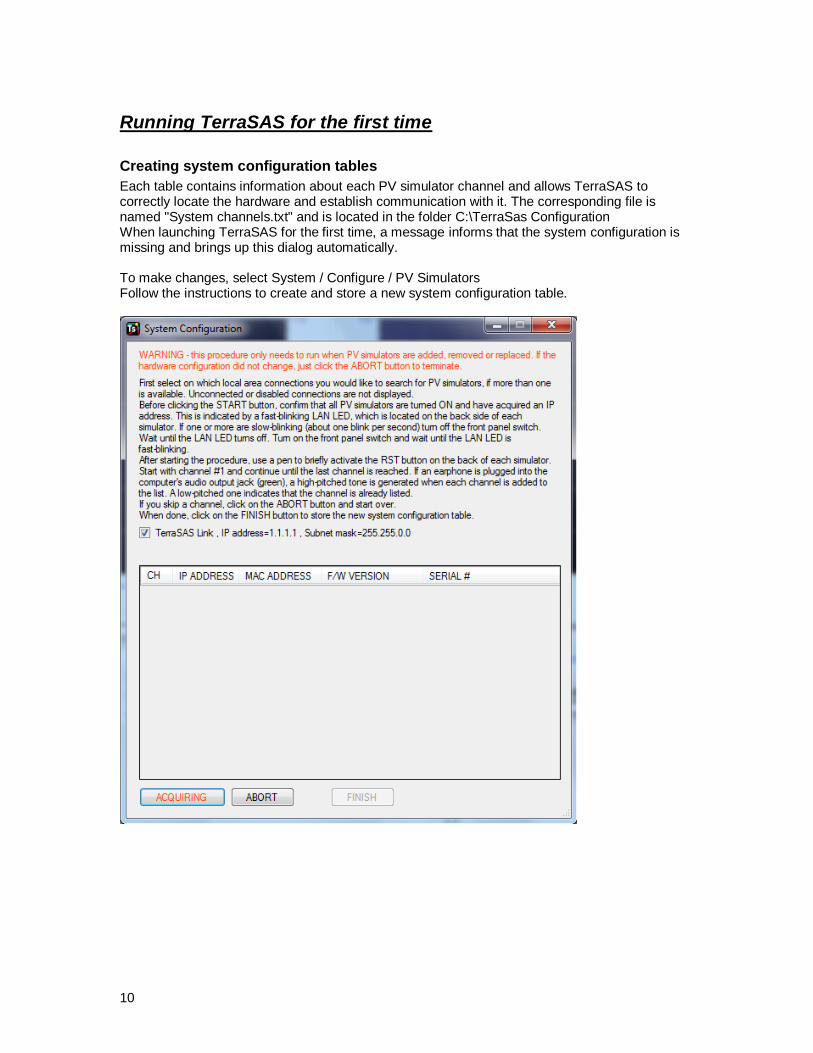
Each table contains information about each PV simulator channel and allows TerraSAS to correctly locate the hardware and establish communication with it. The corresponding file is named "System channels.txt" and is located in the folder C:\TerraSas Configuration When launching TerraSAS for the first time, a message informs that the system configuration is missing and brings up this dialog automatically. To make changes, select System / Configure / PV Simulators Follow the instructions to create and store a new system configuration table.

11
When all desired simulators are located, click the FINISH button. The following dialogue will then be displayed:
Up to four different configurations can be saved. When finished, TerraSAS terminates and needs to be manually restarted. When TerraSAS starts, the default configuration is used. To select a different one, hold down the [SHIFT] key while launching the application. A similar dialogue will allow selecting configurations A, B or C. After restarting, select the System control tab and confirm that all desired channels are online (online channels have a blue tile, offline channels have a grayed-out tile)
12
Saving customized system settings
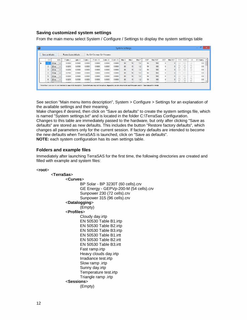
From the main menu select System / Configure / Settings to display the system settings table
See section "Main menu items description", System > Configure > Settings for an explanation of the available settings and their meaning. Make changes if desired, then click on "Save as defaults" to create the system settings file, which is named "System settings.txt" and is located in the folder C:\TerraSas Configuration. Changes to this table are immediately passed to the hardware, but only after clicking "Save as defaults" are stored as new defaults. This includes the button "Restore factory defaults", which changes all parameters only for the current session. If factory defaults are intended to become the new defaults when TerraSAS is launched, click on "Save as defaults". NOTE: each system configuration has its own settings table.
Folders and example files
Immediately after launching TerraSAS for the first time, the following directories are created and filled with example and system files: <root>
<TerraSas> <Curves> BP Solar - BP 3230T (60 cells).crv GE Energy - GEPVp-200-M (54 cells).crv Sunpower 230 (72 cells).crv Sunpower 315 (96 cells).crv <Datalogging> (Empty) <Profiles> Cloudy day.irtp EN 50530 Table B1.irtp EN 50530 Table B2.irtp EN 50530 Table B3.irtp EN 50530 Table B1.irtt EN 50530 Table B2.irtt EN 50530 Table B3.irtt Fast ramp.irtp Heavy clouds day.irtp Irradiance test.irtp Slow ramp .irtp Sunny day.irtp Temperature test.irtp Triangle ramp .irtp <Sessions> (Empty)
13
<TerraSas Configuration> dhcpsrv.exe dhcpsrv.ini READ ME - IMPORTANT NOTICE.txt Simulated system channels.txt Simulated system configuration.txt Serial.txt Curve files were created using the application and data from each manufacturer’s data sheet. Irradiance profiles were created using Microsoft Excel and sample irradiance data provided by Sandia National Laboratories. Files Fast, Slow and Triangle ramp were coded under the guidelines for MPP tracking tests described in the document: “Performance Test Protocol for Evaluating Inverters Used in Grid-Connected Photovoltaic Systems", October 2004, Sandia National Laboratories. Files added to any of the above folders by the user are not altered by the installer when updating the software to later versions. If the directory structure is moved, modified or deleted, a new structure is automatically created. The application never deletes or alters a disk file, even when its corresponding graphics representation is deleted from the graphic pool.
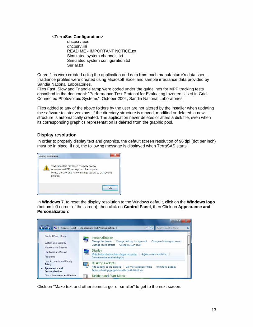
Display resolution
In order to properly display text and graphics, the default screen resolution of 96 dpi (dot per inch) must be in place. If not, the following message is displayed when TerraSAS starts:
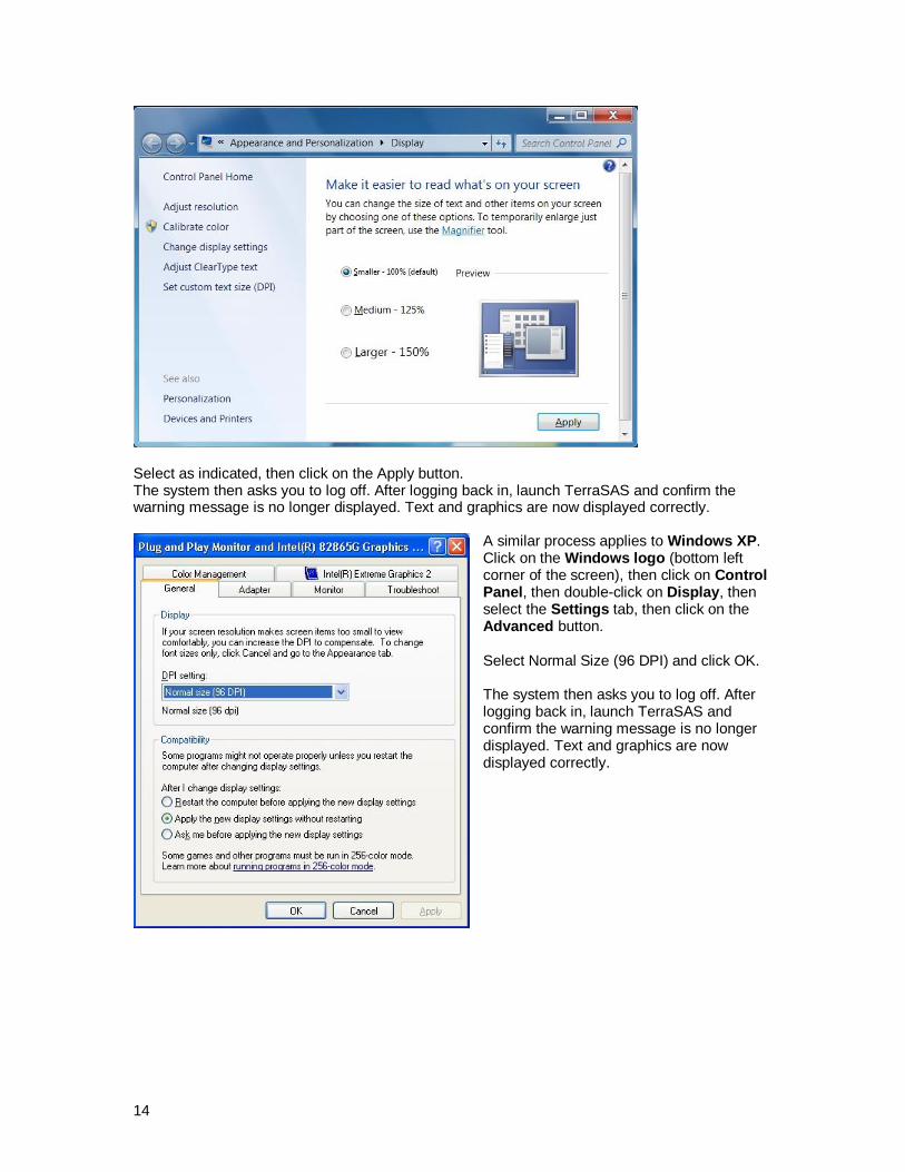
In Windows 7, to reset the display resolution to the Windows default, click on the Windows logo (bottom left corner of the screen), then click on Control Panel, then Click on Appearance and Personalization:
Click on "Make text and other items larger or smaller" to get to the next screen:
14
Select as indicated, then click on the Apply button. The system then asks you to log off. After logging back in, launch TerraSAS and confirm the warning message is no longer displayed. Text and graphics are now displayed correctly.
A similar process applies to Windows XP. Click on the Windows logo (bottom left corner of the screen), then click on Control Panel, then double-click on Display, then select the Settings tab, then click on the Advanced button. Select Normal Size (96 DPI) and click OK. The system then asks you to log off. After logging back in, launch TerraSAS and confirm the warning message is no longer displayed. Text and graphics are now displayed correctly.

15
Software User Guide
Basic concepts Overview
TerraSAS is designed to provide powerful features and ease of use. Its main design goals are:
Easily create photovoltaic curves from manufacturer supplied data, based on the Sandia National Labs model
Create and manage photovoltaic curves based on the EN 50530 model
Easily create irradiance / temperature profiles by entering ramp and dwell timing data
Import photovoltaic curves created with third party applications
Import irradiance / temperature profiles created in Microsoft Excel, third party applications or using real-time data acquisition from actual solar panels
Organize any number of curves and profiles into graphic, filmstrip like pools for intuitive, easy access
Create any number of solar array configurations, organized into a graphic, filmstrip like pool.
Intuitive drag-and-drop interface to easily assign curves and profiles to individual array elements, to support accurate modeling of array shadowing patterns
Simulation preview of each configured array
Comprehensive remote interface based on the SCPI Language
Fully configurable real time trigger, measurement and data logging features
Full hardware monitoring and fault reporting system
Real time control of TerraSAS digital photovoltaic simulator systems (up to 50 channels)
Real time control of standalone, desktop TerraSAS digital photovoltaic simulator units
The picture below shows the System control tab from the main screen.

16
DEMO MODE operation
Click on the TerraSAS icon to select. Hold down the SHIFT and CTRL keys on your keyboard, then double-click the icon to launch TerraSAS. Release both keys when the application starts. By default, DEMO MODE simulates a TerraSAS rack system with 24 low voltage PV simulators (DCS 80V 15A). This can be useful for demonstration or training purposes when physical PV simulators are not available. DEMO MODE operation is indicated on the user interface:
DEMO mode is also useful when developing SCPI scripts. The target system is often busy performing long test sessions and cannot be disturbed. In this case, TerraSAS can be installed on a test computer, launched in DEMO MODE and be remotely controlled by another machine. It is possible to simulate any system architecture by manually building a system configuration file.
While in DEMO MODE, select System>Configure>PV Simulators. Click on the CLEAR button to remove the existing configuration. Select the desired simulator from the pull down control. Click one or more times on the ADD button to add the desired channels. A system (including actual ones) can have any combination of simulator models, up to 48 total channels. Click the button FINISH when done. TerraSAS will terminate and will need to be manually restarted. Restart in DEMO MODE to interact with the new system configuration.
17
Turning the system on and off
PV simulators need to acquire an IP address each time they are turned on. On desktop systems with a single network adapter the IP address is assigned by the organization Intranet. On rack systems, IP addresses are assigned by the DHCP server that runs as a Windows service on the system computer. This service is automatically activated as soon as Windows is loaded and a user logs in. When TerraSAS is launched, it attempts to communicate with all PV simulators listed in the system configuration table. Any off-line channel is tagged as dead and no further communication attempts are made. Dead channels are assigned a grayed-out tile and they only appear in the system configuration table. They are removed from all other locations, such as system setting and programming forms.
Recommended system turn on sequence
Make sure all PV simulators are turned OFF Turn on the main circuit breaker (cabinet systems only) Turn on the computer if not turning on automatically Wait until Windows loads Log in Turn on the front panel ON/OFF switch on all PV simulators Wait about 10 seconds Launch TerraSAS and confirm all channels are online (blue tiles) If one or more channels are dead (gray tiles), close and restart TerraSAS
Recommended system turn off sequence
Select System > Reset Close TerraSAS by clicking on the upper-right [X] on the form Click the Windows 7 logo (bottom left corner) then select Shutdown to turn off the computer Turn off the main circuit breaker (rear panel of rack systems) and the front panel ON/OFF switch on all PV simulators
Graphic chart features in the Photovoltaic simulation tab
When the cursor is in a graphic pane (cross hair shape), use the mouse or touchpad to access the following features: Zoom in: left click, hold down then drag to draw a rectangle and release to zoom to that rectangle Pan: center click and hold down, and then drag to pan in any direction. If using the touchpad, press and hold the CTRL key, left click and hold down, then drag. Menu: right click to access the graphics context menu. This allows to un-zoom, un-pane, show point values, save graphic data to the clipboard, disk file, etc.
Graphic chart features in the System control tab
When the cursor is in a graphic pane (cross hair shape), use the mouse or touchpad to access the following features: Zoom in: left click, hold down then drag to draw a rectangle and release to zoom to that rectangle Zoom in/out: roll the scrolling wheel to zoom in and out. If using the touchpad, slide you finger next to the right edge of the pad to zoom in and out. Pan: center click and hold down, and then drag to pan in any direction. If using the touchpad, press and hold the CTRL key, left click and hold down, then drag. Restore default scale factors: double click just outside the graphic pane (arrow-shaped cursor) Note: all charts in the system control tab are refreshed 20 times per second to show real-time data. When the cursor enters their area, refreshing is suspended to allow the user to interact with the chart. Refreshing is resumed as soon as the cursor leaves the chart.

18
Main menu items description
File > Load Test Session
Select the desired test setup file (previously saved) and click [Open].
File > Save Test Session
Enter a session name and click the [OK] button. This saves the entire test setup to a single XML file. This includes the system configuration, system settings, channels grouping, loaded curves, loaded profiles, arrays and output channels configuration.
Photovoltaic curve > Load (SNL)
Select the desired curve file, and then click Open. The curve is loaded into the graphic pool and can be executed on one or more output channels, or assigned to an array.
Photovoltaic curve > Import (SAM)
This feature allows to quickly import data from solar module libraries. The most recent libraries become available after installing the Solar Advisor Model (SAM). This software can be downloaded from http://www.nrel.gov/analysis/sam/download.html free of charge. The embedded libraries reflect the SAM version available at the time a TerraSAS software release is published, and are listed as TerraSAS: YYYY.MM.DD.
If more than one release of SAM was installed, the pull-down window allows selecting the desired one. The latest one is of course recommended. After loading the desired modules library (Sandia Labs or CEC), browse the list of available solar modules or enter a specific part number (or part of it) to quickly locate it. Press the [ENTER] key or click on the [Keyword search] button to begin searching. When the search is completed, the number of matching modules is reported. Buttons [Next match], [Prev match] and [First match] allow the user to review all matching entries. Double click on the desired module to export all available data to the Add Curve form (see next page). Note that not all parameters in the form are available from the library. Additional data from the manufacturer data sheet can further improve the accuracy of the simulation.

19
Photovoltaic curve > Create (SNL)
Example irradiance chart (Sanyo HIP-200BA19)
Enter the desired Voc, Isc, Vmp, Imp and temperature coefficients normally found in the manufacturer data sheet. Note that some manufacturers provide the voltage coefficient in V/°K or mV/°K. In this case, divide by Voc to obtain the required percentage figure. If an irradiance chart is available, also enter values V1 and E1 into the Irradiance correction parameters. This significantly improves the simulation accuracy. If not, just leave the default values. By checking the "Use form factor" checkbox, Vmp and Imp are calculated from the desired form factor. Assign a name to the curve and click [ADD] to create the disk file and add it to the pool. Note: the curve name is unique and cannot be duplicated. If an identical name exists, an error message is generated. To delete a curve file, use Windows Explorer and navigate to the Curves folder.
Photovoltaic curve > EN 50530:2010 > Create / Update Curve
This feature allows creating and managing an EN 50530 curve. See the advanced programming section for full details.
Photovoltaic curve > EN50530:2010 > Edit coefficients
This feature allows modifying the table of coefficients used in the EN 50530 curve equations. See the advanced programming section for full details.
Photovoltaic curve > Remove > All
This removes all curves from the pool. Disk files are not deleted.
Photovoltaic curve > Remove > Selected
Click on [SEL] to select one or more curves, then access this feature to remove them from the pool. Disk files are not deleted. To deselect, click again on [SEL].
To delete a curve file, use Windows Explorer and navigate to the Curves folder.
E1
Voc V1
E1
V1 V0

20
Irradiance profile > Load
Select the desired profile file, and then click Open. The profile is loaded into the pool and can be executed on one or more output channels.
Irradiance profile > Remove > All
This removes all profiles from the pool. Disk files are not deleted.
Irradiance profile > Remove > Selected
Click on [SEL] to select one or more profiles, then access this feature to remove them from the pool. Disk files are not deleted. To deselect, click again on [SEL].
To delete a profile file, use Windows Explorer and navigate to the Profiles folder.
Irradiance profile > Create
This feature allows creating and editing irradiance / temperature profiles. See the advanced programming section for full details.
Array > Add
Enter the desired array size, assign a name and click on the [ADD] button. The array is added to the pool. Note: the array name is unique and cannot be duplicated. If an identical name exists, an error message is generated. The maximum number of modules within an array is 100. A warning message informs the user when this limit is reached. The newly created array can now be populated, programmed and executed on one or more channels. See section "Executing a static array simulation" for details.
Array > Remove > All
This removes all arrays from the pool. Any channel with an array assigned is switched to curve zero.
Array > Remove > Selected
Select an array by clicking on its perimeter. Selected arrays become highlighted. To deselect, click again. Then access this feature to remove all selected arrays from the pool. When one of more arrays are removed, channels executing these arrays will switch to curve zero.
System > Configure > PV Simulators
This feature is used during system configuration. See section "Running TerraSAS for the first time" for details.

21
System > Configure > Settings
This feature can be accessed at any time to change system settings as needed.
Changes are not saved permanently to disk until the [Save as defaults] button is clicked. The [Restore factory defaults] button returns all settings to their default values. Please see below a brief description of all programmable parameters. AVG – Averaging digital filter This parameter controls the length of the time window over which measurements’ averaging is performed, including true rms power sampling. For best results, AVG should be set to the MPPT sweep period or longer. Low voltage, DCS based simulators allow 0-80ms while high voltage, SG and ETS based simulators allow 0-400ms. Some recent string inverters sweep the MPP at 5 Hz, which equates to 200ms. These inverters will work best with the 200 or 400 ms selection. PID gain coefficients – Overview Default PID coefficients are suitable for most test scenarios and are automatically assigned based on the simulator model. Default PID coefficients work in most situations, however fine tuning them for a specific inverter can improve tracking performance and stability. CAUTION: the output can become unstable during tuning. Always set the OVP (overvoltage protection) to a safe level to prevent damage to the inverter. The OVP setting should be no higher than 80% of the maximum inverter input voltage during tuning. On DCS and legacy simulators, the voltage control loop is analog and the current control loop can be analog or digital. In these models, the PID loop is designed to increase the response speed of the PV simulator. The inverter input current is compared to the current setpoint from the IV curve. The resulting error is fed to the PID controller, which is implemented in the PV simulator firmware. The PID controller output controls the power supply current set input. The PID control loop can be disabled by setting all three coefficients to zero. This can be useful if the digital loop provides no stability or responsiveness improvements. In this mode of operation, the current reference from the IV curve is directly applied to the power supply current set input. PID gain coefficients – Current control [ I ] These three coefficients set the responsiveness of the current control loop. Increasing their values improves the response time but can make the system unstable. The best tradeoff can be determined by trial and error. PID gain coefficients – Voltage control [ V ] These three coefficients set the responsiveness of the voltage control loop. Increasing their values improves the response time but can make the system unstable. The best tradeoff can be determined by trial and error. Latest generation ETS…-PVF simulators feature high speed digital control loops for current and voltage, therefore there are two sets of PID coefficients. Voltage mode coefficients affect the voltage regulation when the inverter is idling and a very small current is flowing. When the inverter starts, the simulator switches to current mode and current mode coefficients become active. The simulator will switch back to voltage mode during transients or turn off, when the inverter current becomes very low.

22
Max V, Max I, Max P, Max OVP, Max OCP Maximum output voltage, current and power. Maximum overvoltage and overcurrent protection. OVP – Overvoltage protection When the specified voltage is reached, the output is turned off and the OVP indicator is lit. This is intended to protect the inverter under test from damage. Reduce the voltage and reset the OVP condition by double-clicking on the OVP indicator. OCP – Overcurrent protection This is only supported on High Power systems. See related section. P/S – Power Supply Mode Places the channel in P/S mode when checked. The IV curve is replaced by a rectangle on all graphics. Irradiance / Temperature programming is replaced by Voltage / Current on all programming dialogs. The output tile turns yellow to show the different operating mode. Channels can be grouped in parallel or series when in P/S mode. D/IS – Disable Interpolation Slope When selected, sudden irradiance changes can be executed. This is desirable when evaluating an inverter’s response to transients. This mode also enables higher precision dynamic measurements. See the EN50530 section for more details. I/L – Inrush Limiter option enable When checked, the inrush limiter module is activated. See the ETS1000 user manual for details about this optional feature. If the optional module is not present or not in use, leave the box unchecked. I/L Energy – Inrush Limiter option threshold programming This is used to program the behavior of the Inrush Limiter option module. See the ETS1000 user manual for details about this optional module. If not present, this parameter should be programmed to zero.
System > Configure > Import inverter data
This feature allows to quickly import data from a solar inverter library. The most recent library becomes available after installing the Solar Advisor Model (SAM). This software can be downloaded from http://www.nrel.gov/analysis/sam/download.html free of charge. The embedded library reflects the SAM version available at the time a TerraSAS software release is published, and is listed as TerraSAS: YYYY.MM.DD.

23
If more than one release of SAM was installed, the pull-down window allows selecting the desired one. The latest one is of course recommended. After loading the library, browse the list of available inverters or enter a specific part number (or part of it) to quickly locate it. Press the [ENTER] key or click on the [Keyword search] button to begin searching. When the search is completed, the number of matching inverters is reported. Buttons [Next match], [Prev match] and [First match] allow the user to highlight and review all matching entries. Double click on the desired inverter to export all available data to the form below, which is automatically launched:
Select the channels to configure, then click on the [Set OVP] button. This brings up the System Settings form, where the OVP setting is automatically entered for the selected channel(s):
Make any adjustments, if needed, and close the form. Then select the desired form factor and click on the [Create IV curve] button. A new curve is created and added to the graphic pool. The maximum power point matches the nominal operating voltage and current of the inverter.
Note that the curve is added to the graphics pool only; it is not saved on disk as usual. Click on the [Execute IV curve] button to execute the curve on the selected channel(s). The inverter is operated at its nominal conditions. Irradiance and temperature can then be manually controlled, or a profile can be associated and executed as usual.

24
System > Reset
This feature performs the following tasks, in the sequence listed below:
Stops all dynamic simulations
Terminates datalogging and closes the file
Terminates triggered measurements
Deletes all curves, profiles and arrays
Resets all channels to curve zero, no profile
Opens all output relays
Resets all channels to default irradiance and temperature System configuration, System settings and Channels grouping are not affected.
System > Debug > Show SCPI traffic
This feature displays a text window that shows all the incoming traffic from the remote interface. It is useful when troubleshooting a remote connection or a new SCPI command script.
System > Debug > Show timing
This feature displays critical timing parameters related to the various execution threads that communicate with the PV simulators.
25
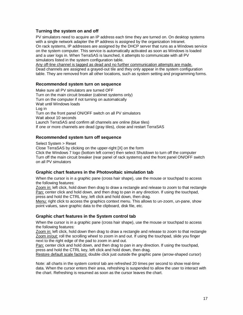
System > Debug > Show errors
This feature logs and displays communication errors that could occur within the PV simulators or on the Ethernet link between TerraSAS and the PV simulators. Place the pointer on the error code to see its description. Possible errors are: Receive error Transmit error Receive timeout Flash memory error RAM memory error Syntax error The first three errors can occasionally occur while testing high power inverters, due to strong electrical noise. However, recurring presence of any errors is an indication of some type of hardware malfunction. To evaluate the severity of the problem, click the [Clear log] button and then close the dialog. Operate the
system for a few hours and then open this screen. If the screen was left open, just click the [Refresh log] button to display updated data. If more than 20 events per hour are logged on any channel, please e-mail error counts and codes
from this screen to [email protected] for an immediate technical review.
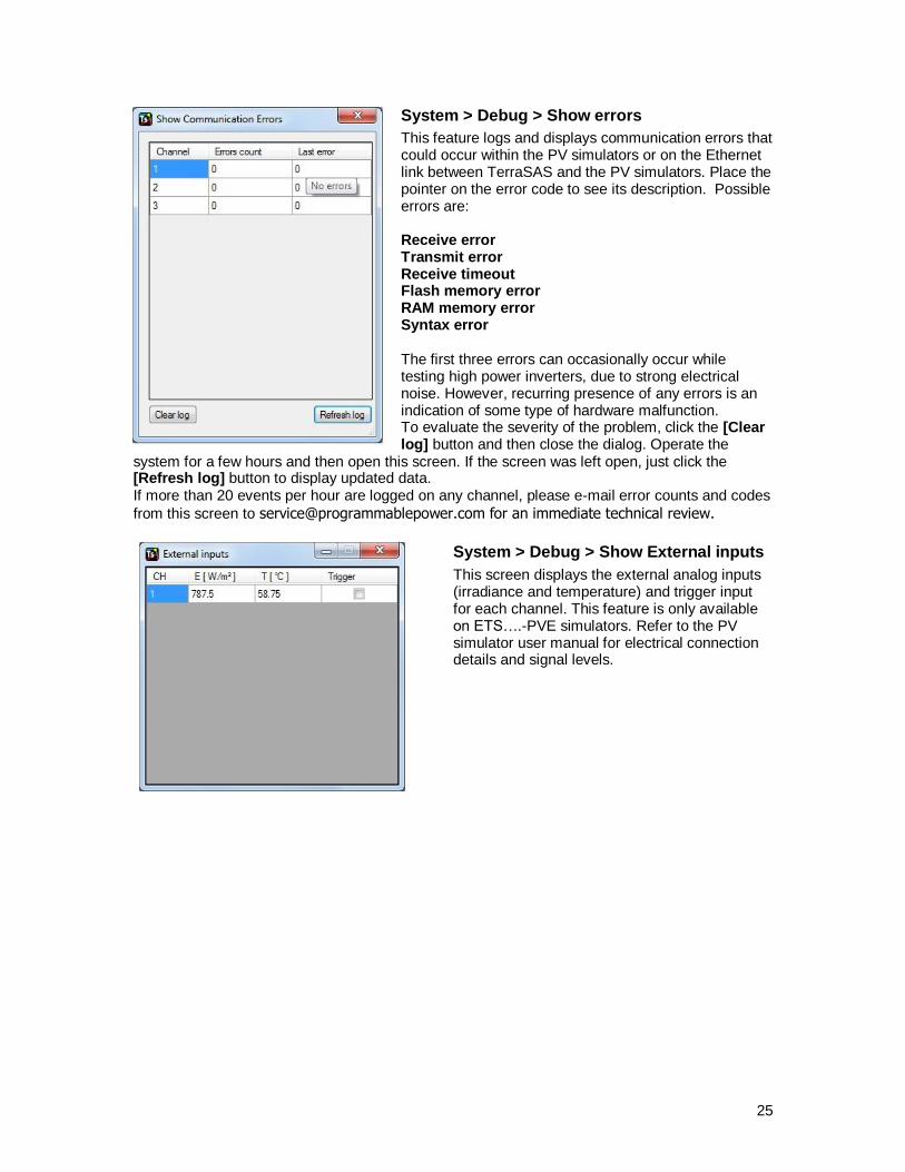
System > Debug > Show External inputs
This screen displays the external analog inputs (irradiance and temperature) and trigger input for each channel. This feature is only available on ETS….-PVE simulators. Refer to the PV simulator user manual for electrical connection details and signal levels.

26
System > Data logging
This feature allows creating a disk file containing measurements for one or more channels at a programmable logging rate:
File format details are in the file formats section of this document. If the specified file already exists in the \\root\TerraSas\Datalogging folder, its contents are replaced with the new data. Once datalogging is started, no changes are allowed until it is stopped.
System > Channels grouping setup
This feature allows creating groups of channels wired in parallel or in series. This creates virtual output channels with higher current or voltage capabilities that behave like physical simulators having higher capabilities. Some restrictions apply when creating channel groups:
Parallel-connected channels must have the same maximum voltage rating. For instance, a 600V SG cannot be paralleled with an 80V DCS.
Series-connected channels should have identical voltage and current ratings. This is
strongly recommended and delivers the best performance. However, the software allows connecting 600V and 1000V PV simulators in series. It also allows mixing power ratings (i.e: 600V/17A in series with 600V/25A). When mixing ratings, the overvoltage protection might behave incorrectly when simulators are back-fed from the inverter under test. There could also be stability issues in some cases.

27
The maximum number of series-connected channels is 3. This is to limit the IV curve distortion that occurs when many channels are wired in series. Additional restrictions apply on high voltage channels wired in series. Consult the system user manual for specific details.
After applying the setup, the lowest channel number within each group becomes the master channel of the group. All other channels within the group become hidden: they no longer have a tile, they do not appear on forms and settings and they cannot be addressed using the remote interface (error 19 - Invalid channel is logged when attempts are made to select hidden channels). The only exception is the command SYSTem:CHANnel:SERial? which retrieves the serial number of the PV simulators. Master channels and their tiles behave like a physical simulator having the combined capabilities of all member channels. The software automatically splits curve and profile data among the physical simulators and calculates measurements accordingly.
System > I/L Energy monitor
This feature displays the Inrush Limiter energy monitor for the selected channel. It is used to monitor the behavior of the inverter under test and determine the programming value of the module’s energy threshold. See the ETS1000 user manual for further details.
IMPORTANT: PV simulators could be seriously damaged when connected in series, as their maximum output to ground voltage rating might be exceeded. The software has no way of knowing when such limit is reached, as it depends on the inverter under test. It is the user responsibility to verify that PV simulators operate within their specified limits, even when the software allows a particular topology.

28
Measure > Time > MPPT Recovery
This feature allows to measure the Maximum Power Point Tracking recovery time as described in the “Performance Test Protocol for Evaluating Inverters Used in Grid-Connected Photovoltaic Systems", October 2004, Sandia National Laboratories, section 5.6.2.2 Test Procedure - Fast Ramp (Intermittent cloud cover).
Measurements are taken on both edges of the fast ramp profile:
Two sets of parameters are provided for each edge: Trigger time: the measurement starts at the indicated profile time. Defaults indicate the end of the leading edge ramp (33 s) and the end of the trailing edge ramp (66 s) Max recovery time: the maximum expected recovery time for the inverter under test MPPT Recovery: the minimum MPPT accuracy that the inverter must meet after recovery Tolerance band: the MPPT accuracy tolerance band that the inverter must meet after recovery. The inverter must be turned on and tracking the MPP before this test can be started.
29
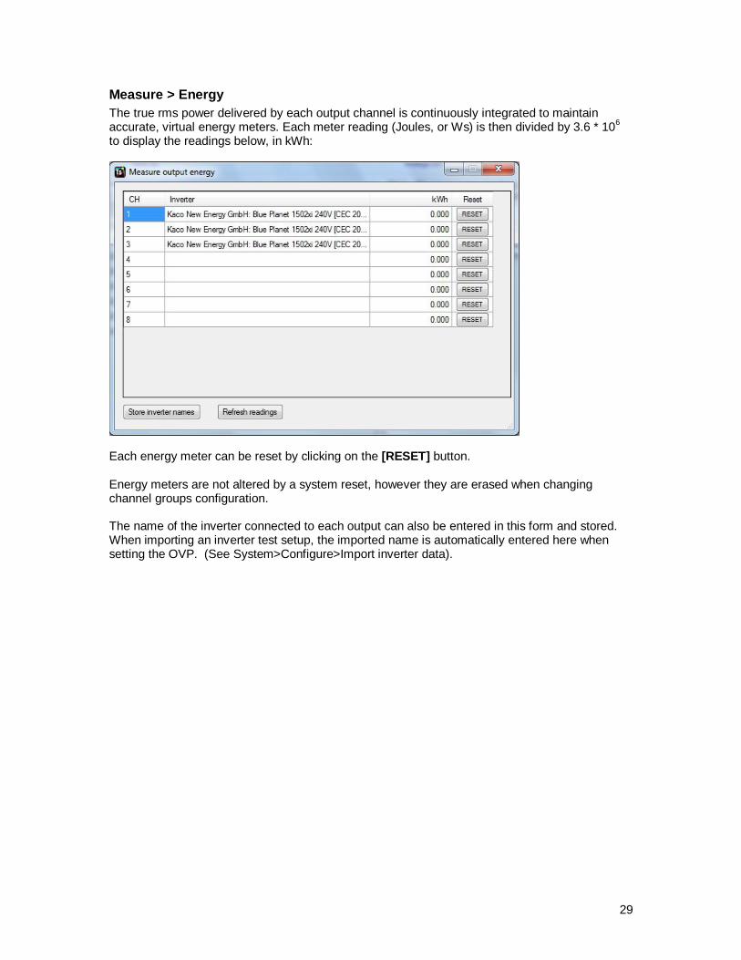
Measure > Energy
The true rms power delivered by each output channel is continuously integrated to maintain accurate, virtual energy meters. Each meter reading (Joules, or Ws) is then divided by 3.6 * 10
6
to display the readings below, in kWh:
Each energy meter can be reset by clicking on the [RESET] button. Energy meters are not altered by a system reset, however they are erased when changing channel groups configuration. The name of the inverter connected to each output can also be entered in this form and stored. When importing an inverter test setup, the imported name is automatically entered here when setting the OVP. (See System>Configure>Import inverter data).

30
User interface details Output channel tile description
Each PV simulator (or group) is graphically represented by a tile, which shows its operating status and reports the most relevant data associated with it.
Voltage, current and power at the input terminals of the inverter under test. The default averaging period is 20ms, which can be changed in the system settings table.
Output channel number
Output relay status. Click to change.
Click to select. Only one tile at a time can be selected. Additional data and real-time graphics are displayed for the selected tile.
Curve number assigned to the output channel. Double click to change to "C0", which is a curve with zero voltage, current and power.
Profile / array number assigned to the output channel. Double click to remove.
Place the pointer on the curve ID to display its name
Place the pointer on the profile / array ID to display its name
Output channel rating

31
Channel faults and protections
Note: additional features and indicators may be present. Refer to each PV simulator user manual for details.
The emergency OFF button or the external interlock has been activated. The PV simulator output is turned off. Deactivate the interlock and push the ON button to turn off this alarm indicator and restore the output.
The output voltage exceeded the OVP threshold programmed in the system settings for this channel. Restore normal conditions and then double click to reset the fault and restore the output. NOTE: this indicator can be marked FLT (fault) depending on the PV simulator model. When this is turned on, an OVP or other power module fault can be the cause. Refer to the PV simulator documentation for more details.
The PV simulator power stage overheated and the output has been turned off. Wait until the unit cools down and the output is restored. This should never occur, even on hot days and full power operation and it is an indication of a hardware malfunction.
The assigned curve or array, translated to the programmed irradiance and temperature, exceeded the maximum voltage or current capability of the channel. The curve has been clipped to fit into the channel's voltage and current ratings.
Place the pointer on the OVP box to display the OVP setpoint

32
Channels grouping
Channels programming
If a curve is assigned to the channel, enter the desired irradiance and temperature using the sliders or typing their values. Click [SET] to transfer the new settings to the PV simulator. Click [DEF] to restore the default values and transfer them to the PV simulator.
If an array is assigned to the channel, the spreadsheet programming tool is displayed. This allows entering individual parameters for each module within the array. Click [Apply changes] to calculate the array and execute the resulting IV curve. Note that each channel is assigned its own copy of the array. Therefore changes performed on one channel do not affect the others, even when they are executing the same array.
This tile represents a group of parallel-connected channels. Current and power readings show the total value for the group. The channel rating also shows the total value.
Click the PGM button to program the channel. See details below. NOTE: Programming is disabled if the channel is
executing a profile.
This tile represents a group of series-connected channels. Voltage and power readings show the total value for the group.

33
A grayed-out tile indicates a loss of communication, which can be temporary or permanent. If a PV simulator is turned off during operation, its tile becomes gray. It goes back to normal when the simulator is turned back on or its communication issue has been fixed. If a simulator is down when TerraSAS launches, it is tagged as dead and will not recover if switched back on. The channel will resume operation when TerraSAS is restarted, if the simulator is back online.
All channels tile description
Curves and profiles dropped on this tile are applied to all channels.
Note: this tile is not displayed on high power systems (large tile) or systems having only one PV simulator.
Click to turn OFF all outputs
Click to turn ON all outputs
Click to assign curve "C0" to all channels
Click to clear profile assignments on all channels
Click the PGM button to bring up the irradiance and temperature set tool. This tool is disabled if any channel is executing a profile. The new settings are transferred to all PV simulators.
If one or more channels have EMG or OVP active, the corresponding indicator is turned on. PRT indicates any other protection.
34
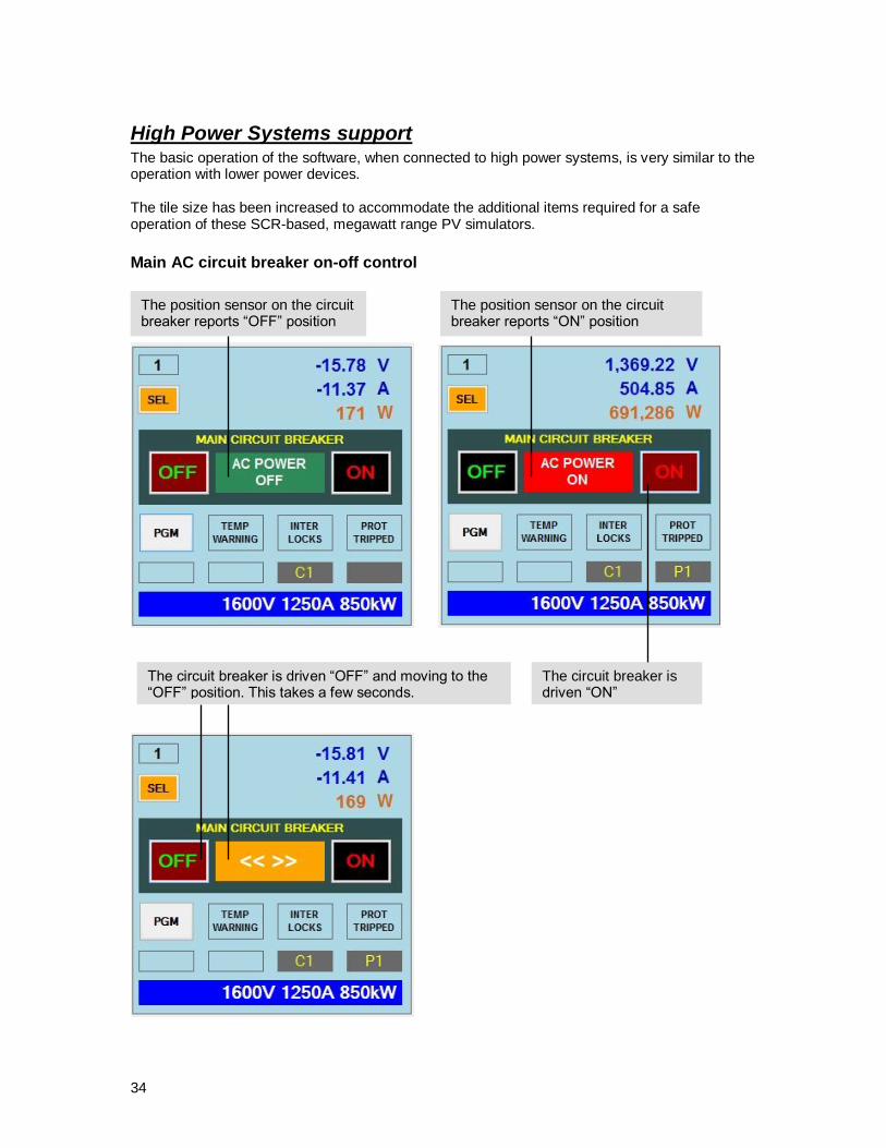
High Power Systems support The basic operation of the software, when connected to high power systems, is very similar to the operation with lower power devices. The tile size has been increased to accommodate the additional items required for a safe operation of these SCR-based, megawatt range PV simulators.
Main AC circuit breaker on-off control
The position sensor on the circuit breaker reports “ON” position
The position sensor on the circuit breaker reports “OFF” position
The circuit breaker is driven “ON”
The circuit breaker is driven “OFF” and moving to the “OFF” position. This takes a few seconds.
35
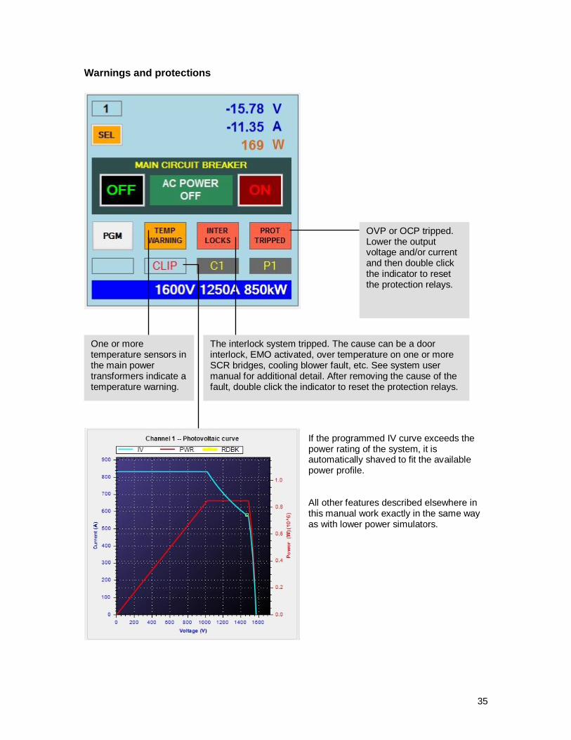
Warnings and protections
If the programmed IV curve exceeds the power rating of the system, it is automatically shaved to fit the available power profile. All other features described elsewhere in this manual work exactly in the same way as with lower power simulators.
OVP or OCP tripped. Lower the output voltage and/or current and then double click the indicator to reset the protection relays.
One or more temperature sensors in the main power transformers indicate a temperature warning.
The interlock system tripped. The cause can be a door interlock, EMO activated, over temperature on one or more SCR bridges, cooling blower fault, etc. See system user manual for additional detail. After removing the cause of the fault, double click the indicator to reset the protection relays.

36
Advanced programming Executing a static simulation
Load or create one or more curves as described in section "TerraSAS main menu items description". Curves in the pool also become listed in the System control tab:
Drag the desired curve name and drop it on one or more tiles to execute. The curve ID number is displayed on the tile. Power is applied to the output as soon as the output relay is turned ON.
If a curve was already assigned to a channel, the new curve replaces it. Select the tile to display additional data:
Soft-starting the inverter under test
When the procedure above is followed, voltage is applied to the inverter as soon as the ON/OFF button is toggled. The output voltage reaches Voc in about 10 ms, depending on the simulator model. If a softer start is desired, turn on the output before dropping the curve on the tile. In this way, the voltage reaches Voc in one second. The same applies when turning off the inverter: first switch to curve zero (double click on the tile's curve ID) and then turn off the output. The output voltage will decrease to zero in one second.
Click here to sort by name Click here to sort by number
Inverter input voltage swing, plotted on the IV curve
Maximum power point tracking efficiency: 100 * inverter input power maximum power point
Peak-to-peak amplitude of the AC component of the inverter input voltage
Peak-to-peak amplitude of the AC component of the inverter input current
IV curve maximum power point

37
Creating and managing EN 50530 test sessions
Select Photovoltaic curve > EN 50530:2010 > Create / Update Curve to display the form below:
EN 50530 curves are designed to operate the solar inverter under test at specific points in its operating range. First specify the rated power, maximum operating voltage, rated operating voltage and minimum operating voltage of the inverter (or other MPP tracking device). Static MPP tracking efficiency tests are always executed at 1000 W/m
2 and 25 °C.
A static test session evaluates 48 points (two technologies, eight power levels and three voltage levels). Data logging is typically turned on for the duration of each measurement. The EN 50530 static MPPT efficiency can be calculated by applying the equations provided in the standard to the data collected in the log files. A dynamic test session is always executed at full rated power (Power level 1.00) and rated voltage. Select Dynamic mode and execute the EN 50530 profiles with data logging turned on. The EN 50530 dynamic MPPT efficiency can be calculated by applying the equations provided in the standard to the data collected in the log files. The shape of the curve can be observed in the Photovoltaic simulation tab after the [CREATE / UDPATE CURVE] button is clicked. The name of the curve is “EN 50530 CURVE”. This curve can be assigned to output channels and executed as described in the previous section. When an output tile has this curve assigned, click the [PGM] button on the tile to bring up the above programming dialog. This allows changing the curve parameters directly on the output channel. Curve changes applied to an output do not affect other outputs or the curve displayed in the Photovoltaic simulation tab.
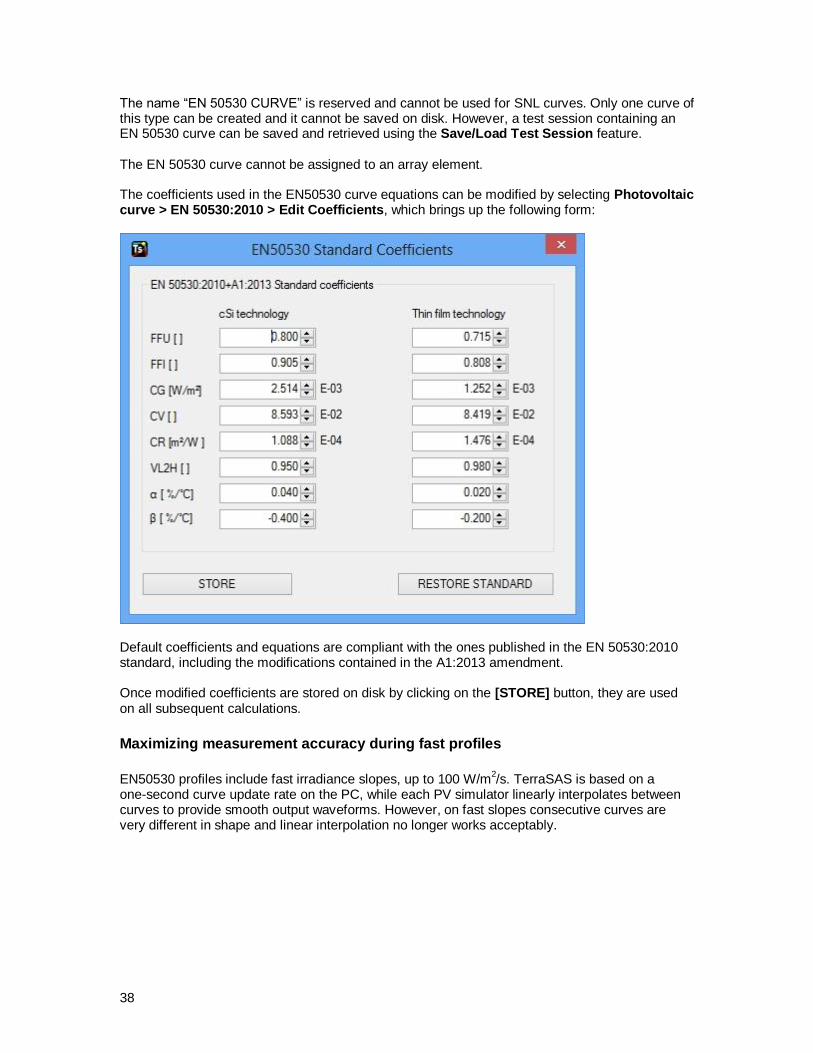
38
The name “EN 50530 CURVE” is reserved and cannot be used for SNL curves. Only one curve of this type can be created and it cannot be saved on disk. However, a test session containing an EN 50530 curve can be saved and retrieved using the Save/Load Test Session feature. The EN 50530 curve cannot be assigned to an array element. The coefficients used in the EN50530 curve equations can be modified by selecting Photovoltaic curve > EN 50530:2010 > Edit Coefficients, which brings up the following form:
Default coefficients and equations are compliant with the ones published in the EN 50530:2010 standard, including the modifications contained in the A1:2013 amendment. Once modified coefficients are stored on disk by clicking on the [STORE] button, they are used on all subsequent calculations.
Maximizing measurement accuracy during fast profiles
EN50530 profiles include fast irradiance slopes, up to 100 W/m
2/s. TerraSAS is based on a
one-second curve update rate on the PC, while each PV simulator linearly interpolates between curves to provide smooth output waveforms. However, on fast slopes consecutive curves are very different in shape and linear interpolation no longer works acceptably.
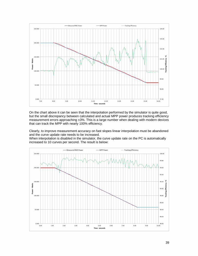
39
97.00
98.00
99.00
100.00
101.00
102.00
103.00
104.00
0.000
50.000
100.000
150.000
200.000
250.000
7.00 8.00 9.00 10.00 11.00 12.00 13.00 14.00 15.00 16.00
Trac
kin
g Ef
fici
ency
-%
Po
wer
-W
atts
Time - seconds
Measured RMS Power MPP Power Tracking Efficiency
On the chart above it can be seen that the interpolation performed by the simulator is quite good, but the small discrepancy between calculated and actual MPP power produces tracking efficiency measurement errors approaching ±3%. This is a large number when dealing with modern devices that can track the MPP with nearly 100% efficiency. Clearly, to improve measurement accuracy on fast slopes linear interpolation must be abandoned and the curve update rate needs to be increased. When interpolation is disabled in the simulator, the curve update rate on the PC is automatically increased to 10 curves per second. The result is below:
98.00
98.20
98.40
98.60
98.80
99.00
99.20
99.40
99.60
99.80
100.00
0.000
50.000
100.000
150.000
200.000
250.000
0.00 1.00 2.00 3.00 4.00 5.00 6.00 7.00 8.00 9.00 10.00
Tra
ckin
g E
ffic
ien
cy -
%
Po
we
r -W
atts
Time - seconds
Measured RMS Power MPP Power Tracking Efficiency
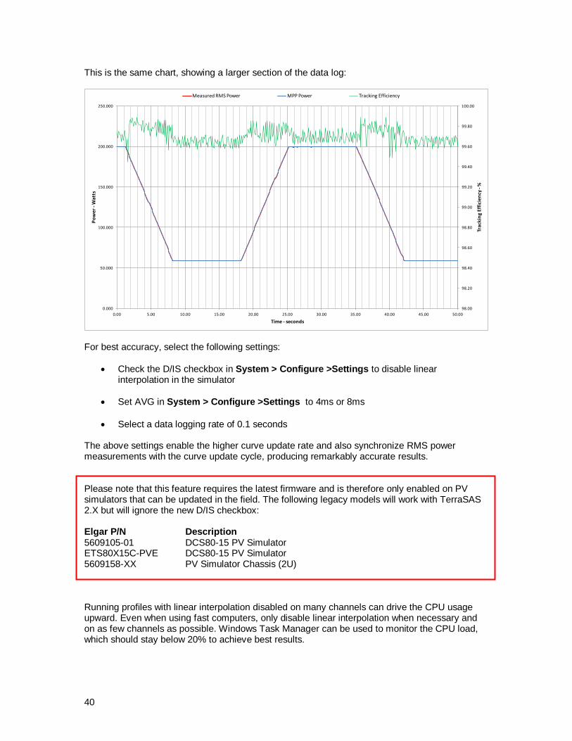
40
This is the same chart, showing a larger section of the data log:
98.00
98.20
98.40
98.60
98.80
99.00
99.20
99.40
99.60
99.80
100.00
0.000
50.000
100.000
150.000
200.000
250.000
0.00 5.00 10.00 15.00 20.00 25.00 30.00 35.00 40.00 45.00 50.00
Tra
ckin
g E
ffic
ien
cy -
%
Po
we
r -W
atts
Time - seconds
Measured RMS Power MPP Power Tracking Efficiency
For best accuracy, select the following settings:
Check the D/IS checkbox in System > Configure >Settings to disable linear interpolation in the simulator
Set AVG in System > Configure >Settings to 4ms or 8ms
Select a data logging rate of 0.1 seconds
The above settings enable the higher curve update rate and also synchronize RMS power measurements with the curve update cycle, producing remarkably accurate results. Please note that this feature requires the latest firmware and is therefore only enabled on PV simulators that can be updated in the field. The following legacy models will work with TerraSAS 2.X but will ignore the new D/IS checkbox: Elgar P/N Description 5609105-01 DCS80-15 PV Simulator ETS80X15C-PVE DCS80-15 PV Simulator 5609158-XX PV Simulator Chassis (2U) Running profiles with linear interpolation disabled on many channels can drive the CPU usage upward. Even when using fast computers, only disable linear interpolation when necessary and on as few channels as possible. Windows Task Manager can be used to monitor the CPU load, which should stay below 20% to achieve best results.

41
Creating an irradiance / temperature profile Select Irradiance profile > Create to display the form below. This form allows entering a lengthy profile as a table by breaking it down into a sequence of segments. Each segment can be ramping from one irradiance/temperature point to another, or dwell at the specified level for a programmable interval. Each row in the table represents two consecutive segments.
Here are a few simple rules to remember:
If the desired profile begins with a flat line, program the Ramp Time to zero.
If there is no flat segment after a ramp, program the Dwell Time to zero.
If temperature profiling is not desired, enter the same temperature on all segments
Blocks of rows can be repeated a programmable number of times
The button [SAVE TABLE] saves the entire table as a .irtt text file.
The button [LOAD TABLE] loads a previously saved table for further editing
The button [CREATE PROFILE] processes the entire table and produces a usable profile, which can be saved on disk as a .irtp text file. This file can be executed but not edited within TerraSAS.
Place the cursor on a row (first column) and press the button [INSERT ROWS] to add rows between existing ones
Highlight a block of rows (select and drag on first column) and then press the [DEL] key to delete them
The button [ADD ROWS] adds rows to the end of the table
Use [Ctrl+C] keys to copy blocks of cells and [Ctrl+V] to paste their contents. For example, the table below produces the profile shown in the next page.

42
Line 1 programs the first flat segment at 100 W/m
2, which lasts for 300 seconds.
Line 2 ramps the irradiance from 100 W/m
2 to 500 W/m
2 in 800 seconds and
then dwells there for 10 seconds. Line 3 ramps the irradiance from 500 W/m
2 to 100 W/m
2 in 800 seconds and
then dwells there for 10 seconds. At the end of line 3, execution continues to the beginning of line 2, so that lines 2 and 3 are executed twice. Line 4 programs the last flat segment at 100 W/m
2, which lasts 300 seconds.
Detail of the dwell segment at the end of each ramp, which lasts 10 seconds.
Standard EN 50530 tables and profiles are provided as examples with the software.

43
Executing a dynamic simulation
Load or create one or more curves and load one or more profiles as described in section "TerraSAS main menu items description". Curves and profiles in the pools also become listed in the System control tab:
Drag the desired curve name and drop it on one or more tiles to execute. The curve ID number is displayed on the tile. Power is applied to the output as soon as the output relay is turned ON.
Drag the desired profile name and drop it on one or more tiles to execute. The profile ID number is displayed on the tile and also added to the dynamic simulation control panel.
The dynamic simulation control panel allows full control of the simulation:
NOTE: On ETS…-PVE simulators the simulation can be started from the external trigger input. See the simulator or system user manual for electrical connection details and signal levels.
Click here to sort by name Click here to sort by number
Click here to sort by name Click here to sort by number
Run simulation, all channels
Go to start point, all channels
Loop mode, toggle all channels
Stop simulation, all channels
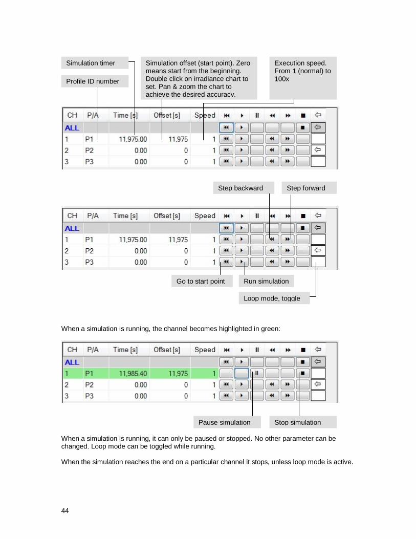
44
When a simulation is running, the channel becomes highlighted in green:
When a simulation is running, it can only be paused or stopped. No other parameter can be changed. Loop mode can be toggled while running. When the simulation reaches the end on a particular channel it stops, unless loop mode is active.
Profile ID number
Simulation timer Simulation offset (start point). Zero means start from the beginning. Double click on irradiance chart to set. Pan & zoom the chart to achieve the desired accuracy.
Execution speed. From 1 (normal) to 100x
Go to start point Run simulation
Pause simulation
Step backward Step forward
Stop simulation
Loop mode, toggle

45
During a dynamic simulation, real time profile and curve data are displayed for the selected channel:
The following features are disabled when one or more channels are executing a dynamic simulation:
Loading, creating and removing curves
Loading and removing profiles
Adding and removing arrays
Changing curve and profile assignments on any channel running a simulation
Manually setting irradiance and temperature on any channel running a simulation
Manually setting irradiance and temperature on tile ALL when one or more channels are running a simulation
Updating the system configuration table (the table can be displayed, but the START button is unavailable)
Changing channels grouping configuration
Executing a dynamic simulation controlled by analog signals
This feature is only available on ETS…-PVE simulators.
Assign a curve to the desired channel and then click the PGM button on its tile. Check the box to translate the curve in real time based on irradiance and temperature analog inputs.
The maximum power point tracking efficiency measurement becomes inaccurate during the execution of fast irradiance profiles. The purpose of the MPP% bar is to provide a quick visual indication of the approximate performance of the unit under test. Accurate MPPT efficiency measurements can only be obtained by executing EN 50530 test protocols.

46
Preparing a static array simulation
The array feature allows simulating the electrical behavior of a solar array by associating IV curves and irradiance profiles to each element in the array. One element usually represents a solar module (also called panel), but can also represent a section of a module for micro-inverter applications. The effects of shading and modules mismatch can be observed and executed on any simulator channel. This often results in IV curves exhibiting two or more peaks in their power curve. The tallest peak is the array's maximum power point, but many solar inverters have troubles finding it. If they do find it during startup, they might switch to a lower peak when irradiance conditions change and the IV curve shape is modified.
Adding and populating an array
After adding at least one array to the graphics pool (see Array>Add), curves and profiles can be assigned to each array element.
Drop on the array name header to assign the same curve or profile to all elements
Press the [SHIFT] key while dropping anywhere on any element to assign the same curve or profile to all elements belonging to that string
Drop anywhere on any element to assign a curve or profile to that element
Place the cursor on the ID box and left-click to drag curves or profiles onto array elements.
Double click on any curve ID to assign curve zero. This can be useful to simulate arrays with strings of different lengths
Double click on any profile ID to remove the association
Each array element can only hold one curve and one profile. When dropping a new curve or profile, the existing one is replaced.
Array element number
Array string number
Bypass diode presence indicator
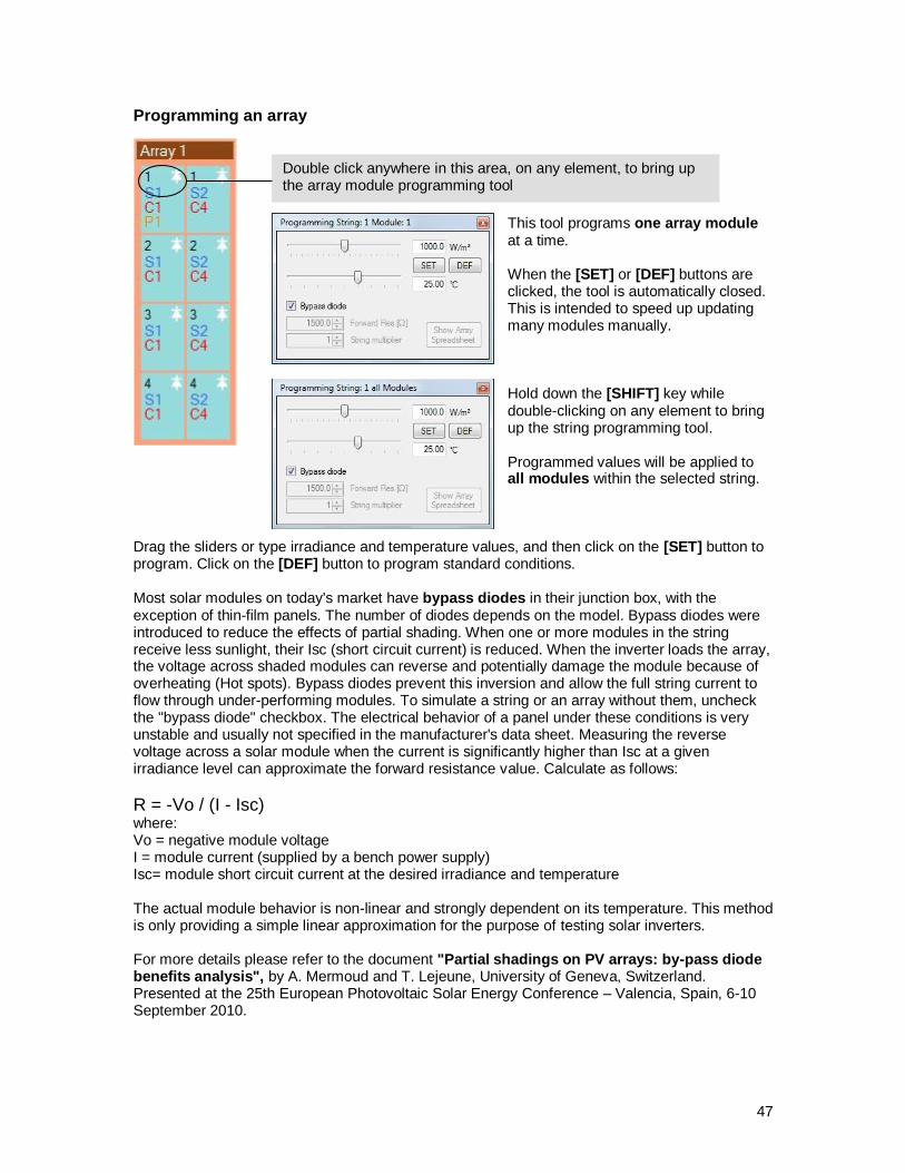
47
Programming an array
This tool programs one array module at a time. When the [SET] or [DEF] buttons are clicked, the tool is automatically closed. This is intended to speed up updating many modules manually. Hold down the [SHIFT] key while double-clicking on any element to bring up the string programming tool. Programmed values will be applied to
all modules within the selected string. Drag the sliders or type irradiance and temperature values, and then click on the [SET] button to program. Click on the [DEF] button to program standard conditions. Most solar modules on today's market have bypass diodes in their junction box, with the exception of thin-film panels. The number of diodes depends on the model. Bypass diodes were introduced to reduce the effects of partial shading. When one or more modules in the string receive less sunlight, their Isc (short circuit current) is reduced. When the inverter loads the array, the voltage across shaded modules can reverse and potentially damage the module because of overheating (Hot spots). Bypass diodes prevent this inversion and allow the full string current to flow through under-performing modules. To simulate a string or an array without them, uncheck the "bypass diode" checkbox. The electrical behavior of a panel under these conditions is very unstable and usually not specified in the manufacturer's data sheet. Measuring the reverse voltage across a solar module when the current is significantly higher than Isc at a given irradiance level can approximate the forward resistance value. Calculate as follows:
R = -Vo / (I - Isc) where: Vo = negative module voltage I = module current (supplied by a bench power supply) Isc= module short circuit current at the desired irradiance and temperature The actual module behavior is non-linear and strongly dependent on its temperature. This method is only providing a simple linear approximation for the purpose of testing solar inverters. For more details please refer to the document "Partial shadings on PV arrays: by-pass diode benefits analysis", by A. Mermoud and T. Lejeune, University of Geneva, Switzerland. Presented at the 25th European Photovoltaic Solar Energy Conference – Valencia, Spain, 6-10 September 2010.
Double click anywhere in this area, on any element, to bring up the array module programming tool
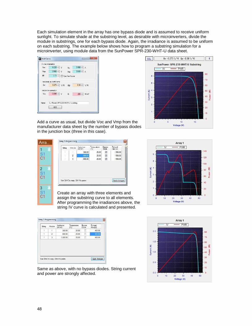
48
Each simulation element in the array has one bypass diode and is assumed to receive uniform sunlight. To simulate shade at the substring level, as desirable with microinverters, divide the module in substrings, one for each bypass diode. Again, the irradiance is assumed to be uniform on each substring. The example below shows how to program a substring simulation for a microinverter, using module data from the SunPower SPR-230-WHT-U data sheet.
Add a curve as usual, but divide Voc and Vmp from the manufacturer data sheet by the number of bypass diodes in the junction box (three in this case).
Create an array with three elements and assign the substring curve to all elements. After programming the irradiances above, the string IV curve is calculated and presented.
Same as above, with no bypass diodes. String current and power are strongly affected.
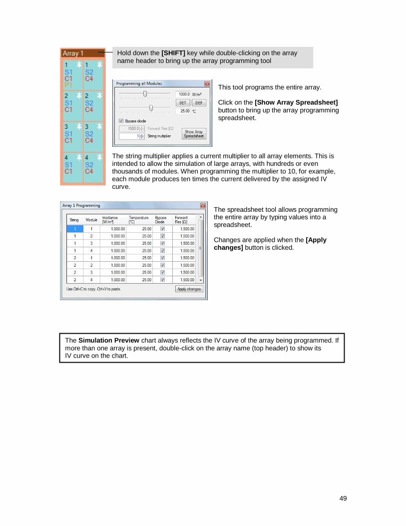
49
This tool programs the entire array. Click on the [Show Array Spreadsheet] button to bring up the array programming spreadsheet.
The string multiplier applies a current multiplier to all array elements. This is intended to allow the simulation of large arrays, with hundreds or even thousands of modules. When programming the multiplier to 10, for example, each module produces ten times the current delivered by the assigned IV curve.
The spreadsheet tool allows programming the entire array by typing values into a spreadsheet. Changes are applied when the [Apply changes] button is clicked.
Hold down the [SHIFT] key while double-clicking on the array name header to bring up the array programming tool
The Simulation Preview chart always reflects the IV curve of the array being programmed. If more than one array is present, double-click on the array name (top header) to show its IV curve on the chart.

50
Executing a static array simulation
Arrays in the graphics pool become listed in the system control tab, just like curves and profiles. Drag the desired array ID on an output tile to execute the array on one or more channels.
Experiment with various irradiance levels to observe the effects on the IV curve and analyze the inverter behavior.
The real-time IV chart shows the inverter tracking behavior as usual. This example was obtained by creating a 2-string array with 10 modules per string. Curve "Sunpower 230 (72 cells)" was assigned to all modules and irradiances were programmed as indicated above. This array configuration is quite common for small residential installations. This simulated IV curve could be observed when a chimney or a tree casts a shadow on three modules in the first string, reducing their irradiance to 20, 50 and 80% of maximum.
As the chart shows, the MPP went from 4600W to 3718W under shade, a 19.1% power loss caused by a 7.5% loss in irradiance.
Click the PGM button to bring up the array programming spreadsheet.
Each channel receives its own copy of the array. Changes applied to the array do not affect other channels, even when assigned the same array. The original array in the Photovoltaic Simulation tab is also not affected.
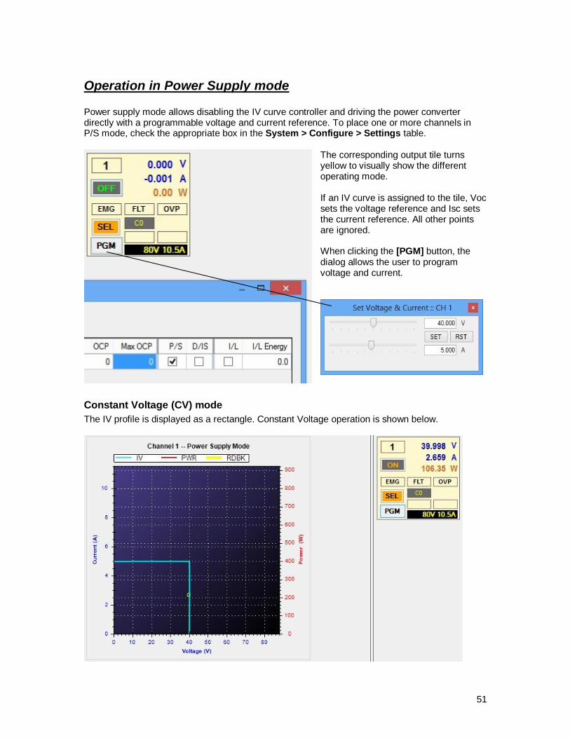
51
Operation in Power Supply mode Power supply mode allows disabling the IV curve controller and driving the power converter directly with a programmable voltage and current reference. To place one or more channels in P/S mode, check the appropriate box in the System > Configure > Settings table.
The corresponding output tile turns yellow to visually show the different operating mode. If an IV curve is assigned to the tile, Voc sets the voltage reference and Isc sets the current reference. All other points are ignored. When clicking the [PGM] button, the dialog allows the user to program voltage and current.
Constant Voltage (CV) mode
The IV profile is displayed as a rectangle. Constant Voltage operation is shown below.

52
Constant Current (CC) mode
The power converter automatically switches to Constant Current operation when the reference current is reached.
As usual when testing power supplies, CV operation was shown above when using an electronic load in CC mode. CC operation was monitored while the electronic load was placed in CV mode.

53
Remote interface operation
Using the SCPI Test utility
The enclosed SCPI Test utility can help you establish a remote connection to TerraSAS for evaluation or test purposes.
In order to connect, you need to know the IP address of the machine running TerraSas. On that machine, click on START / Control Panel / Network and Internet Connections / Network Connections. Right click on the connection of interest, and then select Status. Select the Support tab. The IP address is displayed in the format xxx.xxx.xxx.xxx (Example: 192.168.0.1). Enter the IP address into SCPI Test and leave the default port number: 4944. If SCPI Test is running on the same machine where TerraSAS is running, you can simplify the above process by leaving the default local host address 127.0.0.1. Important: the network adapter must be connected to a network. If the network cable is unplugged, the local host address will become unreachable. Click on the CONNECT button and confirm it becomes the DISCONNECT button. This means that a connection was established successfully.
On the TerraSAS status line (bottom of the user interface) the OFFLINE status should change to ONLINE :
Sending and receiving commands
Now you are ready to type commands (lower text window) and see the responses (upper window). To monitor what TerraSAS is receiving, click on System > Debug > Show SCPI traffic. Command lines need to conform to the following specifications:
Up to 255 characters long
Line terminator is <CR> or <CR><LF> Returned data lines are terminated with <CR><LF>
54
You can also copy and paste the example scripts provided in the install disk into the SEND window. Click SEND to send the entire script and verify correct operation. For a detailed description of all supported SCPI commands and their syntax, please refer to the SCPI Commands Reference section.
Connecting to TerraSAS using third party applications
TerraSAS is always listening for TCP/IP connections on all Ethernet adapters, port 4944. The supported connection type is known as TCP socket, which allows text-based communication using the ASCII character encoding.
IMPORTANT: Telnet and other terminal emulation protocols are not supported and can
cause malfunctions.
55
Release notes
TerraSAS 1.7.5.0 changes and improvements
Added support for the Inrush Limiter option module. See the ETS1000 user manual for details.
Fixed bug on previous release, which caused a crash after extended profiles execution.
TerraSAS 1.7.8.0 changes and improvements
Added test session storage and retrieval (save / load test setup)
Added ability to run PV simulators in power supply mode
Added support for new SCR-controlled High Power PV Systems
Updated SAM libraries to latest NREL release 2013.9.20
Fixed bug preventing OVP settings above 999V
TerraSAS 2.0.0.0 changes and improvements
Tool to create and edit complex irradiance profiles (see Irradiance profile > Create)
EN50530 support (static and dynamic MPP tracking efficiency)
Ability to disable linear interpolation on profiles execution
Longer timeout on PV firmware to allow operation on slow computers
Other minor improvements
Enhanced remote interface. See SCPI reference section for details.
Updated SAM libraries to latest NREL release 2014.1.14
Note: existing SCPI automation scripts will need minor changes to run with TerraSAS release 2.0.0.0 and above. See SCPI reference section for details.
Features for future release
The following new features are planned for release 3.0.0.0:
Execution of complex profiles on array models
IEC61683 support (static and dynamic power conversion efficiency)
56
Reporting software bugs If you find a bug please report it as soon as possible via e-mail to: [email protected] Please include as much detail as possible, such as:
Application name: TerraSAS
Software version you are running (e.g: 1.7.8.0), as reported by Help>About TerraSAS
Description of the malfunction and its adverse effects
Conditions that trigger the malfunction
Curve and profile files used during the malfunctioning simulation
SCPI script that triggers the malfunction, if one was in use
Model of all connected PV simulators

57
This page intentionally left blank.

58
File formats Tab-separated text formats were chosen for the following reasons:
Import and export compatibility with Microsoft Excel and Microsoft Access
Small file size (about 1/6 of the corresponding Excel file)
Fast loading
Human readable The decimal separator for all numeric values is "." (period), regardless of localized versions of the operating system and/or computer system regional settings. This was preferred for the following reasons:
Example and configuration files were created on a US computer
Module and inverter libraries are published in US format
The SCPI Language standard is incompatible with numbers using "," (comma) as the decimal separator.
Curves
Line 1: <max voltage> <tab> <min current> <CR><LF> Line 2: < voltage> <tab> < current> <CR><LF> …. Line 1024: <min voltage> <tab> <max current> <CR><LF> Line 1025: <Beta voltage> <tab> <Beta power> <tab> <K factor> <CR><LF> Beta parameters represent the voltage and power temperature coefficients, expressed in %/°C. The K factor is expressed as:
)ln()ln(
)ln(*
01
0
0
01
EE
E
V
VVk
Where: V0 = Open circuit voltage at reference conditions V1 = Open circuit voltage at lowest known irradiance point E0 = Irradiance at reference conditions (1000 W/m
2)
E1 = Irradiance at lowest known irradiance point (e.g: 200 W/m2)
The suggested number of decimals is 6, which gives 1 uV and 1 uA of resolution. The application converts these values to double precision floating point (64 bits), which is used for all calculations. The number of decimals can be changed with no restrictions. The file format is text (“.txt”) and the file extension must be changed to “.crv”
Irradiance profiles
Line 1: <irradiance> <tab> <temperature> <CR><LF> … Line n: <irradiance> <tab> <temperature> <CR><LF> Irradiance is in Watts/m
2, temperature is in degrees Celsius. Data is in text (“.txt”) form. The
suggested number of decimals is 3, but any other number can be used. There is no limit to the size of the file. Each line represents a fixed one second interval. This matches the hardware simulation and real time interpolation clock, which is crystal controlled. However, file translation to and from other intervals could be accommodated in future releases. The file extension must be changed to “.irtp”.

59
Irradiance profile tables
This file stores an irradiance profile table in text format. This file should only be created and edited using TerraSAS software. The file extension is “.irtt”.
Session files
Session files store an entire test session setup for quick retrieval. They include all curves, profiles, arrays, system configuration, channels grouping and settings. The file format is XML.
Data logging files
Line 1 (column headers): <TIME STAMP><t><CHa measx><t>...<CHa measy><t>...<CHn measx><t>...<CHn measy><CR><LF>
Line 2 (data): <time stamp><t><CHa measx><t>...<CHa measy><t>...<CHn measx><t>...<CHn measy><CR><LF> ..... Line n (data): <time stamp><t><CHa measx><t>...<CHa measy><t>...<CHn measx><t>...<CHn measy><CR><LF>
where: <t> the Tab character <CR> the carriage return character <LF> the line feed character <time stamp> date, time and milliseconds in the format MM/DD/YYYY hh:mm:ss.mmm <CHa measx> first selected measurement on the first selected channel <CHa measy> last selected measurement on the first selected channel <CHn measx> first selected measurement on the last selected channel <CHn meas y> last selected measurement on the last selected channel The file format is Windows text with the standard .txt file extension. Example with time stamp, channel 1, channel 2, DC voltage and DC current selected: TIME STAMP CH1 DCV CH1 DCI CH2 DCV CH2 DCI 8/13/2010 14:09:35.707 4.408666E+001 4.587487E+000 4.408829E+001 4.589466E+000 8/13/2010 14:09:36.689 4.408985E+001 4.585021E+000 4.408901E+001 4.593165E+000 8/13/2010 14:09:37.686 4.408746E+001 4.589313E+000 4.408727E+001 4.584248E+000 8/13/2010 14:09:38.684 4.408948E+001 4.590363E+000 4.408307E+001 4.592713E+000 8/13/2010 14:09:39.681 4.408591E+001 4.588170E+000 4.408640E+001 4.588562E+000 8/13/2010 14:09:40.679 4.408676E+001 4.592735E+000 4.408728E+001 4.591793E+000 8/13/2010 14:09:41.676 4.408202E+001 4.584058E+000 4.408569E+001 4.592407E+000 8/13/2010 14:09:42.674 4.408170E+001 4.592139E+000 4.408165E+001 4.590404E+000
Note: Time stamp and number formats do not follow localized versions of the operating system and/or computer system regional settings. When exporting log files on computers using ","(comma) as the decimal separator, custom import settings need to be used to avoid data corruption. The example below shows how to correctly import logged data in Microsoft Excel:
A similar dialog is available in Microsoft Access when importing text files. This setting is only needed when running TerraSAS on computers using "," (comma) as the decimal separator, as in most European and South American Countries.

60
This page intentionally left blank.
61
TerraSAS SCPI Commands Reference
Overview The SCPI interface allows performing most functions available to the local user from a remote computer. Incoming commands are placed into a memory buffer and executed in the order they are received. Compound commands are processed left to right. While the vast majority of the commands are sequential (they must complete before the next command is processed), some are overlapped. Operations that require time to complete are typically overlapped, to avoid blocking the interface. The following commands initiate an overlapped operation and are included in the pending operation flags:
OUTPut[:STATe] {ON|OFF} [,(@chanlist)]
OUTPut:PROTection:CLEar [(@chanlist)]
ABORt:DLOG
ABORt[:TRANsient] [(@chanlist)]
ABORt:MPPTRecovery
The following commands initiate an overlapped operation and are not included in the pending operation flags:
TRIGger:DLOG[:IMMediate]
TRIGger[:TRANsient][:IMMediate] [(@chanlist)]
TRIGger[:TRANsient][:IMMediate]:PAUse [(@chanlist)]
TRIGger[:TRANsient][:IMMediate]:RESet [(@chanlist)]
TRIGger:MPPTRecovery[:IMMediate]
To synchronize script execution with triggered operations, poll the status word (see the STATus subsystem) Please refer to the SCPI Language standard for complete details about the commands below, with particular regard to syntax, commands structure and sequential/overlapped commands operation. The standard can be downloaded free of charge from this web page: http://www.ivifoundation.org/specifications/default.aspx Or click below to directly download the .PDF document. http://www.ivifoundation.org/docs/scpi-99.pdf A brief SCPI Language tutorial is also provided at the end of this section.

62
Release 2.X SCPI commands update The commands and queries listed below were added. The documentation provided in this manual now includes all 168 commands that are currently supported (132 from software releases 1.X and 36 new ones). SYSTem:CHANnel:MAXPower? [(@chanlist)] SYSTem:CHANnel:MAXOVCurrent? [(@chanlist)] CURVe:EN50530:MPPparms <Pmp>, <Vmp> CURVe:EN50530:MPPparms? CURVe:EN50530:SIMtype {CSI|TF},{STA|DYN} CURVe:EN50530:SIMtype? CURVe:EN50530:ADD [SOURce:]VOLTage <volts> [,(@chanlist)] [SOURce:]VOLTage? [(@chanlist)] [SOURce:]CURRent <amps> [,(@chanlist)] [SOURce:]CURRent? [(@chanlist)] [SOURce:]EN50530:VOLTage <volts> [,(@chanlist)] [SOURce:]EN50530:VOLTage? [(@chanlist)] [SOURce:]EN50530:POWer <watts> [,(@chanlist)] [SOURce:]EN50530:POWer? [(@chanlist)] [SOURce:]EN50530:TECHnology {CSI|TF} [,(@chanlist)] [SOURce:]EN50530:TECHnology? [(@chanlist)] [SOURce:]EN50530:SIMtype {STA|DYN} [,(@chanlist)] [SOURce:]EN50530:SIMtype? [(@chanlist)] [SOURce:]EXECute [,(@chanlist)] [SOURce:]CURRent:PROTection[:LEVel] <value> [,(@chanlist)] [SOURce:]CURRent:PROTection[:LEVel]? [(@chanlist)] SENSe:VPgain <value> [,(@chanlist)] SENSe:VPgain? [(@chanlist)] SENSe:VIgain <value> [,(@chanlist)] SENSe:VIgain? [(@chanlist)] SENSe:VDgain <value> [,(@chanlist)] SENSe:VDgain? [(@chanlist)] SENSe:MODe {PS|PV} [,(@chanlist)] SENSe:MODe? [(@chanlist)] SENSe:INLimiter {ON|OFF} [,(@chanlist)] SENSe:INLimiter? [(@chanlist)] SENSe:ILEnergy <energy> [,(@chanlist)] SENSe:ILEnergy? [(@chanlist)] SENSe:DIslope {ON|OFF} [,(@chanlist)] SENSe:DIslope? [(@chanlist)] The commands listed below were modified to improve performance or support new features. Changes are highlighted. SYSTem:REMote Places the system in remote mode, disabling local user interaction with the graphical interface. It also minimizes the user interface and removes the icon from the Windows taskbar. SYSTem:LOCal Places the system in local mode, enabling local user interaction with the graphical interface. It also maximizes the user interface (full screen) and restores the icon in the Windows taskbar.
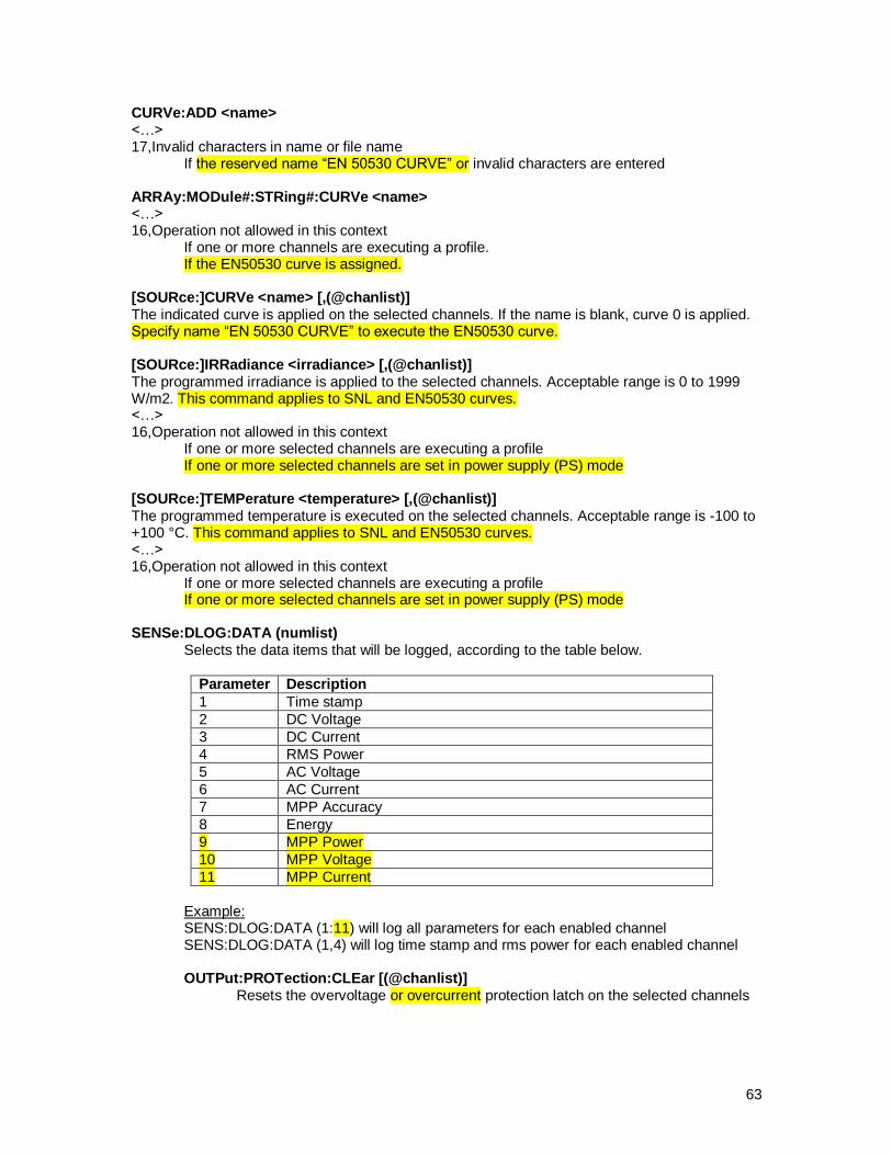
63
CURVe:ADD <name> <…> 17,Invalid characters in name or file name If the reserved name “EN 50530 CURVE” or invalid characters are entered ARRAy:MODule#:STRing#:CURVe <name> <…> 16,Operation not allowed in this context If one or more channels are executing a profile. If the EN50530 curve is assigned. [SOURce:]CURVe <name> [,(@chanlist)] The indicated curve is applied on the selected channels. If the name is blank, curve 0 is applied. Specify name “EN 50530 CURVE” to execute the EN50530 curve. [SOURce:]IRRadiance <irradiance> [,(@chanlist)] The programmed irradiance is applied to the selected channels. Acceptable range is 0 to 1999 W/m2. This command applies to SNL and EN50530 curves. <…> 16,Operation not allowed in this context If one or more selected channels are executing a profile If one or more selected channels are set in power supply (PS) mode [SOURce:]TEMPerature <temperature> [,(@chanlist)] The programmed temperature is executed on the selected channels. Acceptable range is -100 to +100 °C. This command applies to SNL and EN50530 curves. <…> 16,Operation not allowed in this context If one or more selected channels are executing a profile If one or more selected channels are set in power supply (PS) mode SENSe:DLOG:DATA (numlist)
Selects the data items that will be logged, according to the table below.
Parameter Description
1 Time stamp
2 DC Voltage
3 DC Current
4 RMS Power
5 AC Voltage
6 AC Current
7 MPP Accuracy
8 Energy
9 MPP Power
10 MPP Voltage
11 MPP Current
Example: SENS:DLOG:DATA (1:11) will log all parameters for each enabled channel SENS:DLOG:DATA (1,4) will log time stamp and rms power for each enabled channel OUTPut:PROTection:CLEar [(@chanlist)] Resets the overvoltage or overcurrent protection latch on the selected channels

64
Backward compatibility with TerraSAS 1.X SCPI scripts
Existing scripts will require the change described below to continue working. The new command [SOURce:]EXECute [,(@chanlist)] must be added to existing scripts after command sequences that alter :
Irradiance setting
Temperature setting
Curve assignment (curve executed on an output channel)
EN 50530 curve parameters This is because each of the above commands requires the updated curve to be transferred to the PV simulator. This process was previously transparent to the user, but unfortunately causing execution troubles. Consider the script below: Line 1: sour:curv "Sunpower 230 (72 cells)",(@1:3) Line 2: sour:irr 800,(@1:3) Line 3: temp 50,(@1:3) Line 4: sour:irr 1000,(@1:3) On line 1 the selected curve is assigned and executed on channels 1, 2 and 3. This triggered asynchronous internal processes that transmit the curve to each PV simulator. When line 2 is executed, the curve is recalculated and transferred while the previous transfer may still be in progress. This can produce inconsistent results (wrong output voltage / current). Correct results are now obtained by adding one line at the end of the script: Line 1: sour:curv "Sunpower 230 (72 cells)",(@1:3) Line 2: sour:irr 800,(@1:3) Line 3: temp 50,(@1:3) Line 4: sour:irr 1000,(@1:3) Line 5: sour:exec (@1:3) TerraSAS 2.X no longer transfers any curves until the new command in Line 5 is executed. This allows transmitting the updated curve only once, which avoids wasting communication resources and corrupting or dropping curves when overlapped transfers occurred. Scripts written for TerraSAS 1.X will no longer transfer curves when running on TerraSAS 2.X until the new command is added.

65
IEEE-488.2 commands and queries
*CLS
Clears the error queue, the Standard Events Register and all No Operation Pending flags. Possible errors: 1-12 Syntax and parameter mismatch errors
*ESR?
Returns the contents of the Standard Events Register in decimal format. The ESR is an unsigned 32-bit word with the following meaning: ERROR CODE
DECIMAL VALUE DESCRIPTION
1 Operation Complete Flag
1 2 Numeric suffix is an invalid value
2 4 Invalid value in numeric or channel list, e.g. out of range
3 8 Invalid number of dimensions in a channel list
4 16 Parameter of type numeric value overflowed its storage
5 32 Wrong units for parameter
6 64 Wrong type of parameter(s)
7 128 Wrong number of parameters
8 256 Unmatched quotation mark (single/double) in parameters
9 512 Unmatched bracket
10 1024 Command keywords were not recognized
11 2048 No entry in list to retrieve (number list or channel list)
12 4096 Too many dimensions in entry to be returned in parameters
13 8192 File name or name not found
14 16384 File name or name already exists
15 32768 Out of range in one or more numeric values
16 65536 Operation not allowed in this context
17 131072 Invalid characters in name or file name
18 262144 Missing pre-condition, cannot execute command
19 524288 Invalid channel
20 1048576 Invalid channel group
21 2097152 Future use
22 4194304 Future use
23 8388608 Future use
24 16777216 Future use
25 33554432 Future use
26 67108864 Future use
27 134217728 Future use
28 268435456 Future use
29 536870912 Future use
30 1073741824 Future use
31 2147483648 Future use
Possible errors: 1-12 Syntax and parameter mismatch errors

66
*IDN?
Returns product and version information.
Possible errors: 1-12 Syntax and parameter mismatch errors
Example: *IDN? Ametek PPD,TerraSAS,<serial number>,<revision number>
*OPC
Sets the Operation Complete Flag in the Standard Events Register when all pending operations are completed. This is an overlapped command, the parser will continue processing commands without waiting for pending operations to complete. Possible errors: 1-12 Syntax and parameter mismatch errors
*OPC?
Suspends processing further commands until all pending operations are completed, then returns "1". Possible errors: 1-12 Syntax and parameter mismatch errors
*RST
Resets the system. The following tasks are performed:
Suspends processing further commands until the system is reset and ready to accept commands
Stops all dynamic simulations
Terminates datalogging and closes the file
Terminates triggered measurements
Terminates all pending operations
Deletes all curves, profiles and arrays
Resets all channels to curve zero, no profile
Opens all output relays
Resets all channels to default irradiance and temperature
Clears the error queue, the Standard Events Register and all No Operation Pending flags.
System Configuration, System Settings and Channels Grouping are not affected. Possible errors: 1-12 Syntax and parameter mismatch errors
*WAI
Suspends processing further commands until all pending operations are completed. Possible errors: 1-12 Syntax and parameter mismatch errors

67
SYSTem commands and queries
SYSTem:ERRor[:NEXT]?
Returns the next error code and error message in the queue. If the queue is empty, returns “0,No errors”. Possible errors: 1-12 Syntax and parameter mismatch errors
SYSTem:REMote
Places the system in remote mode, disabling local user interaction with the graphical interface. It also minimizes the user interface and removes the icon from the Windows taskbar. Possible errors: 1-12 Syntax and parameter mismatch errors
SYSTem:REMote?
Returns “1” if the system is in remote mode, “0” otherwise Possible errors: 1-12 Syntax and parameter mismatch errors
SYSTem:LOCal
Places the system in local mode, enabling local user interaction with the graphical interface. It also maximizes the user interface (full screen) and restores the icon in the Windows taskbar. Possible errors: 1-12 Syntax and parameter mismatch errors
SYSTem:CHANnel[:COUNt]?
Returns the number of PV simulators in the system. Note that channel and PV simulators count may differ when channels are grouped. See "System>Channels grouping setup" for details.
Possible errors: 1-12 Syntax and parameter mismatch errors
SYSTem:CHANnel:SERial? [(@chanlist)]
Returns the serial number of the PV simulators for the selected channels. Multiple entries are separated by a comma. A dead channel reports "0". Possible errors: 1-12 Syntax and parameter mismatch errors 15,Out of range in one or more numeric values
68
SYSTem:CHANnel:MAXPower? [(@chanlist)]
Returns the maximum power capability of the selected channels. Multiple entries are separated by a comma. Possible errors: 1-12 Syntax and parameter mismatch errors 15,Out of range in one or more numeric values 19,Invalid channel If one or more selected channels are hidden (group slaves)
SYSTem:CHANnel:MAXVoltage? [(@chanlist)]
Returns the maximum voltage capability of the selected channels. Multiple entries are separated by a comma. Possible errors: 1-12 Syntax and parameter mismatch errors 15,Out of range in one or more numeric values 19,Invalid channel If one or more selected channels are hidden (group slaves)
SYSTem:CHANnel:MAXCurrent? [(@chanlist)]
Returns the maximum current capability of the selected channels. Multiple entries are separated by a comma. Possible errors: 1-12 Syntax and parameter mismatch errors 15,Out of range in one or more numeric values 19,Invalid channel If one or more selected channels are hidden (group slaves)
SYSTem:CHANnel:MAXOVervoltage? [(@chanlist)]
Returns the maximum voltage protection setting of the selected channels. Multiple entries are separated by a comma. Possible errors: 1-12 Syntax and parameter mismatch errors 15,Out of range in one or more numeric values 19,Invalid channel If one or more selected channels are hidden (group slaves)
SYSTem:CHANnel:MAXOVCurrent? [(@chanlist)]
Returns the maximum current protection setting of the selected channels. Multiple entries are separated by a comma. Possible errors: 1-12 Syntax and parameter mismatch errors 15,Out of range in one or more numeric values 19,Invalid channel If one or more selected channels are hidden (group slaves)

69
SYSTem:VERSion?
Returns the SCPI language version number.
Possible errors: 1-12 Syntax and parameter mismatch errors
SYSTem:GROup:CATalog?
Returns output channel groups configuration, in the format <ID>,<Mchan>,< MaxVoc >,<MaxIsc>, ... , <ID>,<Mchan>,< MaxVoc >,< MaxIsc > where: <ID> "S" for series or "P" for parallel followed by group number <Mchan> master channel number (the first channel in the group) <MaxVoc> Maximum group voltage <MaxIsc> Maximum group current If there are no groups configured, "G.0" is returned. Please note that groups are actually created when valid groups are first defined and then configured by executing the SYSTem:GROup:SETup command. Possible errors: 1-12 Syntax and parameter mismatch errors Example: Two series groups and two parallel groups, assuming a 24 channels system with 80V 15A PV simulators:
SYST:GRO:DELE:ALL SYST:GRO:DEF:SER 1,(@5,10) SYST:GRO:DEF:PAR 1,(@8:9) SYST:GRO:DEF:PAR 2,(@21:24)
SYST:GRO:DEF:SER 2,(@12,14,15) SYST:GRO:SET
SYST:GRO:CAT? S1,5,160,15,P1,8,80,30,S2,12,240,15,P2,21,80,60
SYSTem:GROup:DELEte:ALL
Deletes all previously entered group definitions. Should be sent first when redefining groups. Possible errors: 1-12 Syntax and parameter mismatch errors
SYSTem:GROup:DEFine:PARallel <group>, (@chanlist)
Defines a group of channels wired in parallel. The maximum group number is half the number of PV simulators in the system.
Possible errors: 1-12 Syntax and parameter mismatch errors 15,Out of range in one or more numeric values

70
SYSTem:GROup:PARallel? <group>
Returns the channel list associated with the group definition. Multiple entries are separated by a comma. If the group does not exist, "G.0" is returned. Possible errors: 1-12 Syntax and parameter mismatch errors 15,Out of range in one or more numeric values Example: SYST:GRO:DELE:ALL SYST:GRO:DEF:PAR 1,(@1:3) SYST:GRO:PAR? 1 1,2,3 SYST:GRO:PAR? 2 G.0
SYSTem:GROup:DEFine:SERies <group>, (@chanlist)
Defines a group of channels wired in series. The maximum group number is half the number of PV simulators in the system. Possible errors: 1-12 Syntax and parameter mismatch errors 15,Out of range in one or more numeric values
SYSTem:GROup:SERies? <group>
Returns the channel list associated with the group definition. Multiple entries are separated by a comma. If the group does not exist, "G.0" is returned. Possible errors: 1-12 Syntax and parameter mismatch errors 15,Out of range in one or more numeric values Example: SYST:GRO:DELE:ALL SYST:GRO:DEF:SER 1,(@1:3) SYST:GRO:SER? 1 1,2,3 SYST:GRO:SER? 2 G.0

71
SYSTem:GROup:SETup
Configures all output channels with all previously defined groups, after validating all entries. None of the groups are actually configured if the validation fails. Upon successful execution, new channel group configurations become effective. All channels are turned off, assigned curve zero, no profile and reset to default irradiance and temperature settings. Possible errors: 1-12 Syntax and parameter mismatch errors 16,Operation not allowed in this context
Profile execution, datalogging or triggered measurements are active on one or more channels
20,Invalid channel group
One or more groups with only one channel assigned had been defined
One or more series groups with more than three members were defined
Channels have incompatible electrical ratings (see "System>Channels grouping setup" for details)
One or more dead channels were included in group definitions Example:
SYST:GRO:DELE:ALL SYST:GRO:DEF:SER 1,(@5,10) SYST:GRO:DEF:PAR 1,(@8:9) SYST:GRO:DEF:PAR 2,(@21:24)
SYST:GRO:DEF:SER 2,(@12,14,15) SYST:GRO:CAT? G.0
SYST:GRO:SET SYST:GRO:CAT? S1,5,160,15,P1,8,80,30,S2,12,240,15,P2,21,80,60 SYST:GRO:DELE:ALL SYST:GRO:CAT? S1,5,160,15,P1,8,80,30,S2,12,240,15,P2,21,80,60 SYST:GRO:SET SYST:GRO:CAT? G.0
72
CURVe subsystem
CURVe:READFile <file name>
Loads a photovoltaic curve from a disk file. The file name must be enclosed in double quotes. The file extension is automatically added. Possible errors: 1-12 Syntax and parameter mismatch errors 13,File name or name not found 14,File name or name already exists 16,Operation not allowed in this context
If one or more channels are executing a profile 17,Invalid characters in name or file name Example: CURV:READF "Sunpower 230 (72 cells)" will load the curve file <Sunpower 230 (72 cells).crv> from the \\root\TerraSas\Curves folder.
CURVe:VIparms <Voc>, <Isc>
Sets Voc and Isc for the curve being added to the graphic pool, at standard test conditions (1000 W/m
2, 25.0 °C). This parameter pair must be sent before any other
when creating a new curve. Possible errors: 1-12 Syntax and parameter mismatch errors 15,Out of range in one or more numeric values 16,Operation not allowed in this context
If one or more channels are executing a profile
CURVe:VIparms?
Returns the last Voc and Isc parameters that were entered, formatted as <Voc>,<Isc> Possible errors: 1-12 Syntax and parameter mismatch errors
CURVe:MPPparms <Vmp>,<Imp>
Sets Vmp and Imp for the curve being added to the graphic pool, at standard test conditions (1000 W/m
2, 25.0 °C). This overwrites any previously entered form factor. The
resulting form factor must be between 0.5 and 0.95. Possible errors: 1-12 Syntax and parameter mismatch errors 15,Out of range in one or more numeric values 16,Operation not allowed in this context
If one or more channels are executing a profile
CURVe:MPPparms?
Returns the last Vmp and Imp parameters that were entered, formatted as <Vmp>,<Imp> Possible errors: 1-12 Syntax and parameter mismatch errors

73
CURVe:FORMfactor <form factor>
Computes Vmp and Imp from the supplied form factor. The allowed range is 0.5 to 0.95. This overwrites any previously entered Vmp, Imp parameters. Possible errors: 1-12 Syntax and parameter mismatch errors 15,Out of range in one or more numeric values 16,Operation not allowed in this context
If one or more channels are executing a profile
CURVe:FORMfactor?
Returns the last form factor that was entered
Possible errors: 1-12 Syntax and parameter mismatch errors
CURVe:BETAparms <Beta V>,<Beta P>
Sets the voltage and power temperature coefficients, expressed in percent values per degree Kelvin. Some manufacturers report the voltage coefficient in mV/ºK. Divide by Voc to obtain a percentage. Allowed range is +1.99 to -1.99. Possible errors: 1-12 Syntax and parameter mismatch errors 15,Out of range in one or more numeric values 16,Operation not allowed in this context
If one or more channels are executing a profile.
CURVe:BETAparms?
Returns the last Beta V and Beta P parameters that were entered, formatted as <Beta V>,<Beta P>. Possible errors: 1-12 Syntax and parameter mismatch errors
CURVe:KFactor <voltage>,<irradiance>
Sets the irradiance correction factor by entering parameters V1 and E1. See "Photovoltaic curve > Create" for more details. The voltage must be equal to or less than Voc. The irradiance must be between 100 and 800 W/m
2.
Possible errors: 1-12 Syntax and parameter mismatch errors 15,Out of range in one or more numeric values 16,Operation not allowed in this context
If one or more channels are executing a profile.
CURVe:KFactor?
Returns the last voltage and irradiance parameters that were entered, formatted as <voltage>,<irradiance>. Possible errors: 1-12 Syntax and parameter mismatch errors

74
CURVe:ADD <name>
Adds a previously characterized photovoltaic curve to the graphic pool and creates a disk file into the \\root\TerraSas\Curves folder, with file name <name>.crv. The curve is digitized to 1,024 points using the equations from Appendix A1, page 37 of the document “Performance Test Protocol for Evaluating Inverters Used in Grid-Connected Photovoltaic Systems", October 2004, Sandia National Laboratories. Possible errors: 1-12 Syntax and parameter mismatch errors 13,File name or name not found 14,File name or name already exists 15,Out of range in one or more numeric values If previously entered numerical parameters are out of range 16,Operation not allowed in this context If one or more channels are executing a profile. 17,Invalid characters in name or file name If the reserved name “EN 50530 CURVE” or invalid characters are entered
CURVe:DELEte <name>
Removes the indicated curve from the graphic pool. The corresponding disk file is not deleted. Disk files can only be deleted manually, using Windows Explorer. Possible errors: 1-12 Syntax and parameter mismatch errors 13,File name or name not found 16,Operation not allowed in this context
If one or more channels are executing a profile.
CURVe:CATalog?
Returns the list of curve names currently loaded in the graphic pool. If there are no curves loaded, "C.0" is returned. Multiple entries are separated by a comma. Possible errors: 1-12 Syntax and parameter mismatch errors
CURVe:EN50530:MPPparms <Pmp>, <Vmp>
Sets maximum power point parameters Pmp (power) and Vmp (voltage) for the EN50530 curve. Possible errors: 1-12 Syntax and parameter mismatch errors 16,Operation not allowed in this context If one or more channels are executing a profile
CURVe:EN50530:MPPparms?
Returns the last Pmp and Vmp parameters that were entered, formatted as <Pmp>,<Vmp> Possible errors: 1-12 Syntax and parameter mismatch errors 18,Missing pre-condition, cannot execute command If no parameters were previously entered
75
CURVe:EN50530:SIMtype {CSI|TF},{STA|DYN}
Sets the technology (crystalline silicon or thin film) and simulation type (static or dynamic) for the EN50530 curve. Irradiance and temperature are set to their default (1000 W/m2 and 25°C). For static simulations, the power level is fixed at 1.00. Power and voltage levels are controlled remotely by programming Pmp and Vmp. Possible errors: 1-12 Syntax and parameter mismatch errors 16,Operation not allowed in this context If one or more channels are executing a profile
CURVe:EN50530:SIMtype?
Returns the last simulation type parameters that were entered, formatted as {CSI|TF},{STA|DYN} Possible errors: 1-12 Syntax and parameter mismatch errors 18,Missing pre-condition, cannot execute command If no parameters were previously entered
CURVe:EN50530:ADD
Adds a previously characterized EN50530 photovoltaic curve to the graphic pool. The curve is digitized to 1,024 points using the equations provided in the EN50530 standard. Coefficients can be edited on the console but cannot be programmed remotely. The curve name is “EN 50530 CURVE”. This name is reserved and cannot be used for SNL curves. If the curve already exists, it is updated. Possible errors: 1-12 Syntax and parameter mismatch errors 18,Missing pre-condition, cannot execute command If no parameters were previously entered

76
PROFile subsystem
PROFile:READFile <file name>
Loads an irradiance profile from a disk file. The file name must be enclosed in double quotes. The file extension is automatically added. Possible errors: 1-12 Syntax and parameter mismatch errors 13,File name or name not found 14,File name or name already exists 16,Operation not allowed in this context
If one or more channels are executing a profile. 17,Invalid characters in name or file name
Example: PROF:READF "Sunny day" will load the profile file <Sunny day.irtp> from the \\root\TerraSas\Profiles folder
PROFile:DELEte <name>
Removes the indicated irradiance profile from the graphic pool. The corresponding disk file is not affected. Possible errors: 1-12 Syntax and parameter mismatch errors 13,File name or name not found 16,Operation not allowed in this context
If one or more channels are executing a profile.
PROFile:CATalog?
Returns the list of profile names currently loaded in the graphic pool and their duration. The format returned is <profile name>.<length in seconds>. Multiple entries are separated by a comma. If there are no profiles loaded, "P.0" is returned. Possible errors: 1-12 Syntax and parameter mismatch errors
77
ARRAy subsystem
ARRAy:SIZE <modules>,<strings>
Defines an array size. The maximum number of modules in an array is 100. Possible errors: 1-12 Syntax and parameter mismatch errors 15,Out of range in one or more numeric values
ARRAy:SIZE?
Returns the last defined array size, in the form <modules>,<strings>. Possible errors: 1-12 Syntax and parameter mismatch errors
ARRAy:ADD <name>
Creates an array and adds it to the graphic pool. The array size must have been previously defined. After creation, the new array is selected and ready to be assigned curves and profiles. Possible errors: 1-12 Syntax and parameter mismatch errors 14,File name or name already exists 16,Operation not allowed in this context
If one or more channels are executing a profile. 17,Invalid characters in name or file name If the array name is blank
ARRAy:SELect <name>
Selects the indicated array. All subsequent curve and profile assignments refer to the currently selected array. Possible errors: 1-12 Syntax and parameter mismatch errors 13,File name or name not found
ARRAy:SELect?
Returns the name of the currently selected array. If no array is selected, "A.0" is returned. Possible errors: 1-12 Syntax and parameter mismatch errors

78
ARRAy:MODule#:STRing#:CURVe <name>
Assigns a curve to the selected array module(s). If the curve name is blank, curve zero is assigned. If the module number is zero, all modules in the string are assigned the same curve. If the string number is zero, the curve is assigned to the selected module on all strings. If both numbers are zero, the curve is assigned to all modules within the array. Possible errors: 1-12 Syntax and parameter mismatch errors 13,File name or name not found If the specified curve does not exist in the graphic pool 15,Out of range in one or more numeric values 16,Operation not allowed in this context
If one or more channels are executing a profile. If the EN50530 curve is assigned.
18,Missing pre-condition, cannot execute command If no array is selected
ARRAy:MODule#:STRing#:CURVe?
Returns the curve name assigned to the selected array module. If no curve was assigned "C.0" is returned. Possible errors: 1-12 Syntax and parameter mismatch errors 15,Out of range in one or more numeric values 18,Missing pre-condition, cannot execute command
If no array is selected
ARRAy:MODule#:STRing#:PROFile <name>
Assigns a profile to the selected array module(s). If the profile name is blank, no profile is assigned. If the module number is zero, all modules in the string are assigned the same profile. If the string number is zero, the profile is assigned to the selected module on all strings. If both numbers are zero, the profile is assigned to all modules within the array. Possible errors: 1-12 Syntax and parameter mismatch errors 13,File name or name not found If the specified profile does not exist in the graphic pool 15,Out of range in one or more numeric values 16,Operation not allowed in this context
If one or more channels are executing a profile. 18,Missing pre-condition, cannot execute command
If no array is selected
ARRAy:MODule#:STRing#:PROFile?
Returns the profile name assigned to the selected array module. If no profile was assigned "P.0" is returned. Possible errors: 1-12 Syntax and parameter mismatch errors 15,Out of range in one or more numeric values 18,Missing pre-condition, cannot execute command
If no array is selected

79
ARRAy:MULTiplier <value>
Programs the currently selected array with the specified current multiplier. Accepted range is an integer between 1 and 1000. The default value is 1, which is assigned when a new array is created. Possible errors: 1-12 Syntax and parameter mismatch errors 15,Out of range in one or more numeric values 18,Missing pre-condition, cannot execute command
If no array is selected
ARRAy:MULTiplier?
Returns the array multiplier for the currently selected array. Possible errors: 1-12 Syntax and parameter mismatch errors 18,Missing pre-condition, cannot execute command
If no array is selected
ARRAy:DELEte <name>
Removes the indicated array from the graphic pool. If the array was selected, the selection is cancelled (ARRAy:SELect? returns "A.0"). If the array was assigned to one or more output channels, assignment is cleared and curve zero is executed. Possible errors: 1-12 Syntax and parameter mismatch errors 13,File name or name not found 16,Operation not allowed in this context
If one or more channels are executing a profile.
ARRAy:CATalog?
Returns the list of array names currently loaded in the graphic pool and their size. The format returned is <array name>.<modules>.<strings>. Multiple entries are separated by a comma. If there are no arrays loaded, "A.0" is returned. Possible errors: 1-12 Syntax and parameter mismatch errors Example: ARRA:SIZE 3,1 ARRA:ADD "Test 1" ARRA:SIZE 4,2 ARRA:ADD "Test 2" ARRA:CAT? Test 1.3.1,Test 2.4.2

80
SOURce subsystem
[SOURce:]CURVe <name> [,(@chanlist)]
The indicated curve is applied on the selected channels. If the name is blank, curve 0 is applied. Specify name “EN 50530 CURVE” to execute the EN50530 curve. Possible errors: 1-12 Syntax and parameter mismatch errors 13,File name or name not found 15,Out of range in one or more numeric values 16,Operation not allowed in this context If one or more selected channels are executing a profile 19,Invalid channel If one or more selected channels are hidden (group slaves)
[SOURce:]CURVe? [(@chanlist)]
Returns the curve name for the selected channels. If no curve was assigned, returns "C.0". Multiple entries are separated by a comma. Possible errors: 1-12 Syntax and parameter mismatch errors 15,Out of range in one or more numeric values 19,Invalid channel If one or more selected channels are hidden (group slaves)
[SOURce:]IRRadiance <irradiance> [,(@chanlist)]
The programmed irradiance is applied to the selected channels. Acceptable range is 0 to 1999 W/m
2. This command applies to SNL and EN50530 curves.
Possible errors: 1-12 Syntax and parameter mismatch errors 15,Out of range in one or more numeric values 16,Operation not allowed in this context
If one or more selected channels are executing a profile If one or more selected channels are set in power supply (PS) mode
19,Invalid channel If one or more selected channels are hidden (group slaves)
[SOURce:]IRRadiance? [(@chanlist)]
Returns the irradiance setpoint for the selected channels. Multiple entries are separated by a comma. Possible errors: 1-12 Syntax and parameter mismatch errors 15,Out of range in one or more numeric values 19,Invalid channel If one or more selected channels are hidden (group slaves)

81
[SOURce:]TEMPerature <temperature> [,(@chanlist)]
The programmed temperature is executed on the selected channels. Acceptable range is -100 to +100 °C. This command applies to SNL and EN50530 curves. Possible errors: 1-12 Syntax and parameter mismatch errors 15,Out of range in one or more numeric values 16,Operation not allowed in this context If one or more selected channels are executing a profile
If one or more selected channels are set in power supply (PS) mode 19,Invalid channel If one or more selected channels are hidden (group slaves)
[SOURce:]TEMPerature? [(@chanlist)]
Returns the temperature setpoint for the selected channels. Multiple entries are separated by a comma. Possible errors: 1-12 Syntax and parameter mismatch errors 15,Out of range in one or more numeric values 19,Invalid channel If one or more selected channels are hidden (group slaves)
[SOURce:]VOLTage <volts> [,(@chanlist)]
The specified voltage setpoint is applied to the selected channels. This setpoint is only valid in power supply (PS) mode. Possible errors: 1-12 Syntax and parameter mismatch errors 15,Out of range in one or more numeric values 16,Operation not allowed in this context
If one or more selected channels are set in photovoltaic (PV) mode 19,Invalid channel If one or more selected channels are hidden (group slaves)
[SOURce:]VOLTage? [(@chanlist)]
Returns the voltage setpoint for the selected channels. Multiple entries are separated by a comma. Possible errors: 1-12 Syntax and parameter mismatch errors 15,Out of range in one or more numeric values 19,Invalid channel If one or more selected channels are hidden (group slaves)
82
[SOURce:]CURRent <amps> [,(@chanlist)]
The specified current setpoint is applied to the selected channels. This setpoint is only valid in power supply (PS) mode. Possible errors: 1-12 Syntax and parameter mismatch errors 15,Out of range in one or more numeric values 16,Operation not allowed in this context If one or more selected channels are set in photovoltaic (PV) mode 19,Invalid channel If one or more selected channels are hidden (group slaves)
[SOURce:]CURRent? [(@chanlist)]
Returns the current setpoint for the selected channels. Multiple entries are separated by a comma. Possible errors: 1-12 Syntax and parameter mismatch errors 15,Out of range in one or more numeric values 19,Invalid channel If one or more selected channels are hidden (group slaves)
[SOURce:]EN50530:VOLTage <volts> [,(@chanlist)]
The specified EN50530 maximum power point voltage is applied to the selected channels. Possible errors: 1-12 Syntax and parameter mismatch errors 15,Out of range in one or more numeric values 16,Operation not allowed in this context If one or more selected channels are set in power supply (PS) mode If one or more selected channels are not executing an EN50530 curve 19,Invalid channel If one or more selected channels are hidden (group slaves)
[SOURce:]EN50530:VOLTage? [(@chanlist)]
Returns the EN50530 maximum power point voltage for the selected channels. Multiple entries are separated by a comma. Possible errors: 1-12 Syntax and parameter mismatch errors 15,Out of range in one or more numeric values 19,Invalid channel If one or more selected channels are hidden (group slaves)
83
[SOURce:]EN50530:POWer <watts> [,(@chanlist)]
The specified EN50530 maximum power point power is applied to the selected channels. Possible errors: 1-12 Syntax and parameter mismatch errors 15,Out of range in one or more numeric values 16,Operation not allowed in this context If one or more selected channels are set in power supply (PS) mode If one or more selected channels are not executing an EN50530 curve 19,Invalid channel If one or more selected channels are hidden (group slaves)
[SOURce:]EN50530:POWer? [(@chanlist)]
Returns the EN50530 maximum power point power for the selected channels. Multiple entries are separated by a comma. Possible errors: 1-12 Syntax and parameter mismatch errors 15,Out of range in one or more numeric values 19,Invalid channel If one or more selected channels are hidden (group slaves)
[SOURce:]EN50530:TECHnology {CSI|TF} [,(@chanlist)]
The specified EN50530 technology type (crystalline silicon or thin film) is applied to the selected channels. Possible errors: 1-12 Syntax and parameter mismatch errors 15,Out of range in one or more numeric values 16,Operation not allowed in this context If one or more selected channels are set in power supply (PS) mode If one or more selected channels are not executing an EN50530 curve 19,Invalid channel If one or more selected channels are hidden (group slaves)
[SOURce:]EN50530:TECHnology? [(@chanlist)]
Returns the EN50530 technology type formatted as {CSI|TF}. Multiple entries are separated by a comma. Possible errors: 1-12 Syntax and parameter mismatch errors 15,Out of range in one or more numeric values 19,Invalid channel If one or more selected channels are hidden (group slaves)
84
[SOURce:]EN50530:SIMtype {STA|DYN} [,(@chanlist)]
The specified EN50530 simulation type (static or dynamic) is applied to the selected channels. Possible errors: 1-12 Syntax and parameter mismatch errors 15,Out of range in one or more numeric values 16,Operation not allowed in this context If one or more selected channels are set in power supply (PS) mode If one or more selected channels are not executing an EN50530 curve 19,Invalid channel If one or more selected channels are hidden (group slaves)
[SOURce:]EN50530:SIMtype? [(@chanlist)]
Returns the EN50530 simulation type formatted as {STA|DYN}. Multiple entries are separated by a comma. Possible errors: 1-12 Syntax and parameter mismatch errors 15,Out of range in one or more numeric values 19,Invalid channel If one or more selected channels are hidden (group slaves)
[SOURce:]EXECute [,(@chanlist)]
All previously programmed curve parameters are calculated and transferred to the PV simulator(s). This command applies to SNL and EN50530 curves. Possible errors: 1-12 Syntax and parameter mismatch errors 15,Out of range in one or more numeric values 16,Operation not allowed in this context
If one or more selected channels are executing a profile If one or more selected channels are set in power supply (PS) mode
19,Invalid channel If one or more selected channels are hidden (group slaves)
[SOURce:]PROFile <name> [,(@chanlist)]
The indicated profile is sent to the selected channels. Execution starts when a trigger command is received. If one or more channels in the list are executing a profile, error 16 is generated. Possible errors: 1-12 Syntax and parameter mismatch errors 13,File name or name not found 15,Out of range in one or more numeric values 16,Operation not allowed in this context
If one or more selected channels are executing a profile 19,Invalid channel If one or more selected channels are hidden (group slaves)
85
[SOURce:]PROFile? [(@chanlist)]
Returns the profile name for the selected channels. If no profile is assigned, returns "P.0". Multiple entries are separated by a comma. Possible errors: 1-12 Syntax and parameter mismatch errors 15,Out of range in one or more numeric values
If one or more selected channels are executing a profile 19,Invalid channel If one or more selected channels are hidden (group slaves)
[SOURce:]PROFile:OFFSet <value> [,(@chanlist)]
Sets the starting time (offset) of the profile for the selected channels. Possible errors: 1-12 Syntax and parameter mismatch errors 15,Out of range in one or more numeric values
If the offset value falls outside the profile time span on one or more selected channels
16,Operation not allowed in this context If one or more selected channels are executing a profile 18,Missing pre-condition, cannot execute command If one or more channels do not have a profile assigned 19,Invalid channel If one or more selected channels are hidden (group slaves)
[SOURce:]PROFile:OFFSet? [(@chanlist)]
Returns the profile offset for the selected channels. Multiple entries are separated by a comma. Possible errors: 1-12 Syntax and parameter mismatch errors 15,Out of range in one or more numeric values 19,Invalid channel If one or more selected channels are hidden (group slaves)
[SOURce:]VOLTage:PROTection[:LEVel] <value> [,(@chanlist)]
Sets the overvoltage protection threshold on the selected channels
Possible errors: 1-12 Syntax and parameter mismatch errors 15,Out of range in one or more numeric values 19,Invalid channel
If one or more selected channels are hidden (group slaves)

86
[SOURce:]VOLTage:PROTection[:LEVel]? [(@chanlist)]
Returns the overvoltage protection threshold on the selected channels. Multiple entries are separated by a comma. Possible errors: 1-12 Syntax and parameter mismatch errors 15,Out of range in one or more numeric values 19,Invalid channel If one or more selected channels are hidden (group slaves)
[SOURce:]CURRent:PROTection[:LEVel] <value> [,(@chanlist)]
Sets the overcurrent protection threshold on the selected channels
Possible errors: 1-12 Syntax and parameter mismatch errors 15,Out of range in one or more numeric values 19,Invalid channel
If one or more selected channels are hidden (group slaves)
[SOURce:]CURRent:PROTection[:LEVel]? [(@chanlist)]
Returns the overcurrent protection threshold on the selected channels. Multiple entries are separated by a comma. Possible errors: 1-12 Syntax and parameter mismatch errors 15,Out of range in one or more numeric values 19,Invalid channel If one or more selected channels are hidden (group slaves)
[SOURce:]ARRAy <name> [,(@chanlist)]
The indicated array is executed on the selected channels. If the name is blank, array execution is terminated and curve 0 is executed. Possible errors: 1-12 Syntax and parameter mismatch errors 13,File name or name not found 16,Operation not allowed in this context If one or more selected channels are executing a profile 15,Out of range in one or more numeric values 19,Invalid channel If one or more selected channels are hidden (group slaves)
[SOURce:]ARRAy? [(@chanlist)]
Returns the array name for the selected channels. If no array was assigned, returns "A.0". Multiple entries are separated by a comma. Possible errors: 1-12 Syntax and parameter mismatch errors 15,Out of range in one or more numeric values 19,Invalid channel If one or more selected channels are hidden (group slaves)

87
SOURce#:ARRAy:MODule#:STRing#:IRRadiance <irradiance>
The indicated array module(s) on the selected channel are programmed with the specified irradiance level. If the module number is zero, all modules in the string are programmed. If the string number is zero, the selected module is programmed on all strings. If both numbers are zero, all modules within the array are programmed. Acceptable range is 0 to 1999 W/m
2.
Possible errors: 1-12 Syntax and parameter mismatch errors 15,Out of range in one or more numeric values 16,Operation not allowed in this context If the selected channel is executing a profile 18,Missing pre-condition, cannot execute command If the channel does not have an array assigned 19,Invalid channel If the selected channel is hidden (group slaves)
SOURce#:ARRAy:MODule#:STRing#:IRRadiance?
Returns the irradiance level for the selected array module and channel 1-12 Syntax and parameter mismatch errors 15,Out of range in one or more numeric values 18,Missing pre-condition, cannot execute command If the selected channel does not have an array assigned 19,Invalid channel If the selected channel is hidden (group slaves)
SOURce#:ARRAy:MODule#:STRing#:TEMPerature <temperature>
The indicated array module(s) on the selected channel are programmed with the specified temperature level. If the module number is zero, all modules in the string are programmed. If the string number is zero, the selected module is programmed on all strings. If both numbers are zero, all modules within the array are programmed. Acceptable range is -100 to +100 °C. Possible errors: 1-12 Syntax and parameter mismatch errors 15,Out of range in one or more numeric values 16,Operation not allowed in this context If the selected channel is executing a profile 18,Missing pre-condition, cannot execute command If the channel does not have an array assigned 19,Invalid channel If the selected channel is hidden (group slaves)
SOURce#:ARRAy:MODule#:STRing#:TEMPerature?
Returns the temperature level for the selected channel and array module. 1-12 Syntax and parameter mismatch errors 15,Out of range in one or more numeric values 18,Missing pre-condition, cannot execute command If the selected channel does not have an array assigned 19,Invalid channel If the selected channel is hidden (group slaves)

88
SOURce#:ARRAy:MODule#:STRing#:DIOde {YES|NO}
The indicated array module(s) on the selected channel are programmed with the specified bypass diode option. If the module number is zero, all modules in the string are programmed. If the string number is zero, the selected module is programmed on all strings. If both numbers are zero, all modules within the array are programmed. Possible errors: 1-12 Syntax and parameter mismatch errors 15,Out of range in one or more numeric values 16,Operation not allowed in this context If the selected channel is executing a profile 18,Missing pre-condition, cannot execute command If the channel does not have an array assigned 19,Invalid channel If the selected channel is hidden (group slaves)
SOURce#:ARRAy:MODule#:STRing#:DIOde?
Returns the diode option state (YES or NO) for the selected channel and array module. 1-12 Syntax and parameter mismatch errors 15,Out of range in one or more numeric values 18,Missing pre-condition, cannot execute command If the selected channel does not have an array assigned 19,Invalid channel If the selected channel is hidden (group slaves)
SOURce#:ARRAy:MODule#:STRing#:RESistance <resistance>
The indicated array module(s) on the selected channel are programmed with the specified forward resistance. If the module number is zero, all modules in the string are programmed. If the string number is zero, the selected module is programmed on all strings. If both numbers are zero, all modules within the array are programmed. Acceptable range is 0 to 100 kohms. Possible errors: 1-12 Syntax and parameter mismatch errors 15,Out of range in one or more numeric values 16,Operation not allowed in this context If the selected channel is executing a profile 18,Missing pre-condition, cannot execute command If the channel does not have an array assigned 19,Invalid channel If the selected channel is hidden (group slaves)
SOURce#:ARRAy:MODule#:STRing#:RESistance?
Returns the forward resistance for the selected channel and array module. 1-12 Syntax and parameter mismatch errors 15,Out of range in one or more numeric values 18,Missing pre-condition, cannot execute command If the selected channel does not have an array assigned 19,Invalid channel If the selected channel is hidden (group slaves)

89
SOURce#:ARRAy:EXECute
The array is calculated and the resulting IV curve is executed on the selected channel. Possible errors: 1-12 Syntax and parameter mismatch errors 15,Out of range in one or more numeric values 16,Operation not allowed in this context If the selected channel is executing a profile 18,Missing pre-condition, cannot execute command If the channel does not have an array assigned 19,Invalid channel If the selected channel is hidden (group slaves)

90
STATus subsystem
STATus:OPERation:CONDition? [(@chanlist)]
Returns the operating status of the selected channels. If the channel list is omitted, bit positions marked with X are reported for the system level status. For example, if one or more channels are executing a profile, bit 6 will be set. Multiple entries are separated by a comma.
BIT POSITION
DECIMAL VALUE
SYST DESCRIPTION
0 1 X Interlock or emergency switch active
1 2 X Overvoltage protection tripped
2 4 X Overtemperature protection active
3 8 X Communication loss (offline)
4 16 X Dead channel (offline when TerraSAS started)
5 32 X Clipping (voltage or current exceeds maximum)
6 64 X Profile execution is running
7 128 Profile execution is paused
8 256 Channel is a member of a parallel-wired group
9 512 Channel is a member of a series-wired group 10 1024 X Datalogging in progress
11 2048 X Triggered measurement in progress
12 4096 Future use
13 8192 Future use
14 16384 Future use
15 32768 Future use
Possible errors: 1-12 Syntax and parameter mismatch errors 15,Out of range in one or more numeric values 19,Invalid channel
If one or more selected channels are hidden (group slaves)
91
SENSe subsystem
SENSe:DLOG:TINTerval <value>
Sets the datalogging interval. Acceptable values are between 0.05 and 3600 seconds. Values are rounded to the nearest 0.05s multiple. Possible errors: 1-12 Syntax and parameter mismatch errors 15,Out of range in one or more numeric values
SENSe:DLOG:TINTerval?
Returns the datalogging interval.
Possible errors: 1-12 Syntax and parameter mismatch errors
SENSe:DLOG:NAME <name>
Sets the datalogging file name. If left blank, a name is automatically generated as follows: <Data log YYYY-MM-DD-HH-MM-SS-mmm>. The disk file is created and data logging will start when a trigger command is received. If the selected file name already exists on disk, its contents are replaced with the new data. After this command is executed, datalogging is placed into an "armed" condition that can only be triggered or aborted. No other changes are allowed. Possible errors: 1-12 Syntax and parameter mismatch errors 15,Out of range in one or more numeric values 16,Operation not allowed in this context If datalogging is already active or the datalogging file is already open 17,Invalid characters in name or file name
SENSe:DLOG:NAME?
Returns the active datalog file name. If no open file exists, returns "D.0" Possible errors: 1-12 Syntax and parameter mismatch errors
SENSe:DLOG:ENABle [(@chanlist)]
Enables datalogging on the selected channels. Possible errors: 1-12 Syntax and parameter mismatch errors 15,Out of range in one or more numeric values 16,Operation not allowed in this context
If the log file is open or datalogging is active. 19,Invalid channel If one or more selected channels are hidden (group slaves)

92
SENSe:DLOG:ENABle? [(@chanlist)]
Returns the datalogging state of the selected channels. Multiple entries are separated by a comma. Possible errors: 1-12 Syntax and parameter mismatch errors 15,Out of range in one or more numeric values 19,Invalid channel If one or more selected channels are hidden (group slaves)
SENSe:DLOG:DATA (numlist)
Selects the data items that will be logged, according to the table below.
Parameter Description
1 Time stamp
2 DC Voltage
3 DC Current
4 RMS Power
5 AC Voltage
6 AC Current
7 MPP Accuracy
8 Energy
9 MPP voltage
10 MPP current
11 MPP power
Possible errors: 1-12 Syntax and parameter mismatch errors 15,Out of range in one or more numeric values 16,Operation not allowed in this context
If the log file is open or datalogging is active. Example: SENS:DLOG:DATA (1:11) will log all parameters for each enabled channel SENS:DLOG:DATA (1,4) will log time stamp and rms power for each enabled channel
SENSe:DLOG:DATA?
Returns the data items that are selected for datalogging. Possible errors: 1-12 Syntax and parameter mismatch errors Example: SENS:DLOG:DATA (1:8)
SENS:DLOG:DATA? 1,2,3,4,5,6,7,8 If no parameter is selected, "0" is returned.

93
SENSe:PROFile:SPeed <value> [,(@chanlist)]
Sets the irradiance profile execution speed for the selected channels. Accepted range is 1 to 100. Possible errors: 1-12 Syntax and parameter mismatch errors 15,Out of range in one or more numeric values 16,Operation not allowed in this context
If one or more selected channels are executing a profile 19,Invalid channel
If one or more selected channels are hidden (group slaves)
SENSe:PROFile:SPeed? [(@chanlist)]
Returns the irradiance profile execution speed for the selected channels. Multiple entries are separated by a comma. Possible errors: 1-12 Syntax and parameter mismatch errors 15,Out of range in one or more numeric values 19,Invalid channel
If one or more selected channels are hidden (group slaves)
SENSe:PROFile:LOOP {ON|OFF} [,(@chanlist)]
Sets profile execution in loop mode on the selected channels. When the end of the profile is reached, execution restarts from the offset time index. Possible errors: 1-12 Syntax and parameter mismatch errors 15,Out of range in one or more numeric values 19,Invalid channel
If one or more selected channels are hidden (group slaves)
SENSe:PROFile:LOOP? [(@chanlist)]
Returns the loop mode state for the selected channels: ON if active, OFF if inactive. Multiple entries are separated by a comma. Possible errors: 1-12 Syntax and parameter mismatch errors 15,Out of range in one or more numeric values 19,Invalid channel If one or more selected channels are hidden (group slaves)
SENSe:AVERage {OFF|4|8|20|40|80|200|400} [,(@chanlist)]
Sets the measurement averaging period for the selected channels, in milliseconds. Low voltage (80V) PV simulators are limited to 80ms, high voltage (600/1000V) accept the full range. Possible errors: 1-12 Syntax and parameter mismatch errors 15,Out of range in one or more numeric values 19,Invalid channel If one or more selected channels are hidden (group slaves)

94
SENSe:AVERage? [(@chanlist)]
Returns the measurement averaging period for the selected channels. Multiple entries are separated by a comma. Possible errors: 1-12 Syntax and parameter mismatch errors 15,Out of range in one or more numeric values 19,Invalid channel If one or more selected channels are hidden (group slaves)
SENSe:Pgain <value> [,(@chanlist)]
Sets the proportional gain coefficient for the selected channels. Acceptable values are 0 to 0.9999. Possible errors: 1-12 Syntax and parameter mismatch errors 15,Out of range in one or more numeric values 19,Invalid channel If one or more selected channels are hidden (group slaves)
SENSe:Pgain? [(@chanlist)]
Returns the proportional gain coefficient for the selected channels. Multiple entries are separated by a comma. Possible errors: 1-12 Syntax and parameter mismatch errors 15,Out of range in one or more numeric values 19,Invalid channel If one or more selected channels are hidden (group slaves)
SENSe:Igain <value> [,(@chanlist)]
Sets the integral gain coefficient for the selected channels. Acceptable values are 0 to 0.9999. Possible errors: 1-12 Syntax and parameter mismatch errors 15,Out of range in one or more numeric values 19,Invalid channel If one or more selected channels are hidden (group slaves)
SENSe:Igain? [(@chanlist)]
Returns the integral gain coefficient for the selected channels. Multiple entries are separated by a comma. Possible errors: 1-12 Syntax and parameter mismatch errors 15,Out of range in one or more numeric values 19,Invalid channel If one or more selected channels are hidden (group slaves)

95
SENSe:Dgain <value> [,(@chanlist)]
Sets the derivative gain coefficient for the selected channels. Acceptable values are 0 to 0.9999. Possible errors: 1-12 Syntax and parameter mismatch errors 15,Out of range in one or more numeric values 19,Invalid channel If one or more selected channels are hidden (group slaves)
SENSe:Dgain? [(@chanlist)]
Returns the derivative gain coefficient for the selected channels. Multiple entries are separated by a comma. Possible errors: 1-12 Syntax and parameter mismatch errors 15,Out of range in one or more numeric values 19,Invalid channel If one or more selected channels are hidden (group slaves)
SENSe:VPgain <value> [,(@chanlist)]
Sets the proportional voltage gain coefficient for the selected channels. Acceptable values are 0 to 0.9999. Possible errors: 1-12 Syntax and parameter mismatch errors 15,Out of range in one or more numeric values 19,Invalid channel If one or more selected channels are hidden (group slaves)
SENSe:VPgain? [(@chanlist)]
Returns the proportional voltage gain coefficient for the selected channels. Multiple entries are separated by a comma. Possible errors: 1-12 Syntax and parameter mismatch errors 15,Out of range in one or more numeric values 19,Invalid channel If one or more selected channels are hidden (group slaves)
SENSe:VIgain <value> [,(@chanlist)]
Sets the integral voltage gain coefficient for the selected channels. Acceptable values are 0 to 0.9999. Possible errors: 1-12 Syntax and parameter mismatch errors 15,Out of range in one or more numeric values 19,Invalid channel If one or more selected channels are hidden (group slaves)
96
SENSe:VIgain? [(@chanlist)]
Returns the integral voltage gain coefficient for the selected channels. Multiple entries are separated by a comma. Possible errors: 1-12 Syntax and parameter mismatch errors 15,Out of range in one or more numeric values 19,Invalid channel If one or more selected channels are hidden (group slaves)
SENSe:VDgain <value> [,(@chanlist)]
Sets the derivative voltage gain coefficient for the selected channels. Acceptable values are 0 to 0.9999. Possible errors: 1-12 Syntax and parameter mismatch errors 15,Out of range in one or more numeric values 19,Invalid channel If one or more selected channels are hidden (group slaves)
SENSe:VDgain? [(@chanlist)]
Returns the derivative voltage gain coefficient for the selected channels. Multiple entries are separated by a comma. Possible errors: 1-12 Syntax and parameter mismatch errors 15,Out of range in one or more numeric values 19,Invalid channel If one or more selected channels are hidden (group slaves)
SENSe:MODe {PS|PV} [,(@chanlist)]
Sets the operating mode of the selected channels. PS sets the channel in power supply mode (voltage and current programming), PV sets the channel in photovoltaic simulation mode (irradiance and temperature programming). Possible errors: 1-12 Syntax and parameter mismatch errors 15,Out of range in one or more numeric values 19,Invalid channel If one or more selected channels are hidden (group slaves)
SENSe:MODe? [(@chanlist)]
Returns the operating mode of the selected channels, formatted as {PS|PV}. Multiple entries are separated by a comma. Possible errors: 1-12 Syntax and parameter mismatch errors 15,Out of range in one or more numeric values 19,Invalid channel If one or more selected channels are hidden (group slaves)

97
SENSe:INLimiter {ON|OFF} [,(@chanlist)]
Enables or disables the inrush limiter option. If this optional module is not installed on the PV simulator, this command has no effect. Possible errors: 1-12 Syntax and parameter mismatch errors 15,Out of range in one or more numeric values 19,Invalid channel If one or more selected channels are hidden (group slaves)
SENSe:INLimiter? [(@chanlist)]
Returns the status of the inrush limiter option of the selected channels, formatted as {ON|OFF}. Multiple entries are separated by a comma. Possible errors: 1-12 Syntax and parameter mismatch errors 15,Out of range in one or more numeric values 19,Invalid channel If one or more selected channels are hidden (group slaves)
SENSe:ILEnergy <energy> [,(@chanlist)]
Sets the energy threshold of the inrush limiter option. If this optional module is not installed on the PV simulator, this command has no effect. Possible errors: 1-12 Syntax and parameter mismatch errors 15,Out of range in one or more numeric values 19,Invalid channel If one or more selected channels are hidden (group slaves)
SENSe:ILEnergy? [(@chanlist)]
Returns the status of the inrush limiter option of the selected channels, formatted as {ON|OFF}. Multiple entries are separated by a comma. Possible errors: 1-12 Syntax and parameter mismatch errors 15,Out of range in one or more numeric values 19,Invalid channel If one or more selected channels are hidden (group slaves)
SENSe:DIslope {ON|OFF} [,(@chanlist)]
Disables the 1-second linear interpolation slope during profiles execution. Possible errors: 1-12 Syntax and parameter mismatch errors 15,Out of range in one or more numeric values 19,Invalid channel If one or more selected channels are hidden (group slaves)
98
SENSe:DIslope? [(@chanlist)]
Returns the status of the profile interpolation feature, formatted as {ON|OFF}. Multiple entries are separated by a comma. Possible errors: 1-12 Syntax and parameter mismatch errors 15,Out of range in one or more numeric values 19,Invalid channel If one or more selected channels are hidden (group slaves)
SENSe:MPPTRecovery:CURVe <name>
Sets the curve name to be used for the maximum power point recovery time measurement. Name validation performed at the time the measurement is started (see TRIGger:MPPTRecovery[:IMMediate] command). This command does not load the curve file from disk. Possible errors: 1-12 Syntax and parameter mismatch errors 16,Operation not allowed in this context If the measurement is already in progress
SENSe:MPPTRecovery:CURVe?
Returns the curve name to be used for the maximum power point recovery time measurement. Possible errors: 1-12 Syntax and parameter mismatch errors
SENSe:MPPTRecovery:PROFile <name>
Sets the profile name to be used for the maximum power point recovery time measurement. Name validation performed at the time the measurement is started (see TRIGger:MPPTRecovery[:IMMediate] command). This command does not load the profile file from disk. Possible errors: 1-12 Syntax and parameter mismatch errors 16,Operation not allowed in this context If the measurement is already in progress
SENSe:MPPTRecovery:PROFile?
Returns the profile name to be used for the maximum power point recovery time measurement. Possible errors: 1-12 Syntax and parameter mismatch errors

99
SENSe:MPPTRecovery:TRIGger <leading edge>,<trailing edge>
Sets the trigger point for leading and trailing edge measurements, referred to the irradiance profile timing scale. Acceptable values are 0 to 100,000. Additional validation performed at the time the measurement is started (see TRIGger:MPPTRecovery[:IMMediate] command) Possible errors: 1-12 Syntax and parameter mismatch errors 15,Out of range in one or more numeric values 16,Operation not allowed in this context If the measurement is already in progress
SENSe:MPPTRecovery:TRIGger?
Returns the trigger point for leading and trailing edge measurements, referred to the irradiance profile timing scale Possible errors: 1-12 Syntax and parameter mismatch errors
SENSe:MPPTRecovery:MAXimum <leading edge>,<trailing edge>
Sets the maximum recovery time expected for leading and trailing edge measurements. Acceptable values are 0 to 100,000. Additional validation performed at the time the measurement is started (see TRIGger:MPPTRecovery[:IMMediate] command) Possible errors: 1-12 Syntax and parameter mismatch errors 15,Out of range in one or more numeric values 16,Operation not allowed in this context If the measurement is already in progress
SENSe:MPPTRecovery:MAXimum?
Returns the maximum recovery time expected for leading and trailing edge measurements Possible errors: 1-12 Syntax and parameter mismatch errors
SENSe:MPPTRecovery:VALue <leading edge>,<trailing edge>
Sets the desired MPP accuracy after recovery for leading and trailing edge measurements. Acceptable values are 50 to 100. Possible errors: 1-12 Syntax and parameter mismatch errors 15,Out of range in one or more numeric values 16,Operation not allowed in this context If the measurement is already in progress
100
SENSe:MPPTRecovery:VALue?
Returns the desired MPP accuracy after recovery for leading and trailing edge measurements Possible errors: 1-12 Syntax and parameter mismatch errors
SENSe:MPPTRecovery:TOLerance <leading edge>,<trailing edge>
Sets the desired MPP accuracy tolerance after recovery for leading and trailing edge measurements. Acceptable values are 0.1 to 20. Possible errors: 1-12 Syntax and parameter mismatch errors 15,Out of range in one or more numeric values 16,Operation not allowed in this context If the measurement is already in progress
SENSe:MPPTRecovery:TOLerance?
Returns the desired MPP accuracy tolerance after recovery for leading and trailing edge measurements. Possible errors: 1-12 Syntax and parameter mismatch errors
SENSe:MPPTRecovery:ENABle [(@chanlist)]
Enables maximum power point recovery time measurement on the selected channels. Possible errors: 1-12 Syntax and parameter mismatch errors 15,Out of range in one or more numeric values 16,Operation not allowed in this context If the measurement is already in progress or any channels are executing a profile 19,Invalid channel If one or more selected channels are hidden (group slaves)
SENSe:MPPTRecovery:ENABle? [(@chanlist)]
Returns the maximum power point recovery time measurement state of the selected channels. Multiple entries are separated by a comma. Possible errors: 1-12 Syntax and parameter mismatch errors 15,Out of range in one or more numeric values 19,Invalid channel If one or more selected channels are hidden (group slaves)

101
SENSe:ENERgy:RESet [(@chanlist)]
Resets the energy reading of each selected channel. Possible errors: 1-12 Syntax and parameter mismatch errors 15,Out of range in one or more numeric values 19,Invalid channel If one or more selected channels are hidden (group slaves)
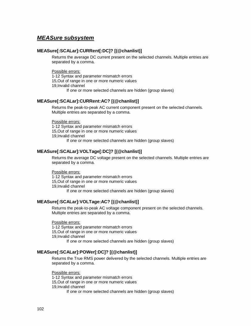
102
MEASure subsystem
MEASure[:SCALar]:CURRent[:DC]? [(@chanlist)]
Returns the average DC current present on the selected channels. Multiple entries are separated by a comma. Possible errors: 1-12 Syntax and parameter mismatch errors 15,Out of range in one or more numeric values 19,Invalid channel If one or more selected channels are hidden (group slaves)
MEASure[:SCALar]:CURRent:AC? [(@chanlist)]
Returns the peak-to-peak AC current component present on the selected channels. Multiple entries are separated by a comma. Possible errors: 1-12 Syntax and parameter mismatch errors 15,Out of range in one or more numeric values 19,Invalid channel If one or more selected channels are hidden (group slaves)
MEASure[:SCALar]:VOLTage[:DC]? [(@chanlist)]
Returns the average DC voltage present on the selected channels. Multiple entries are separated by a comma. Possible errors: 1-12 Syntax and parameter mismatch errors 15,Out of range in one or more numeric values 19,Invalid channel If one or more selected channels are hidden (group slaves)
MEASure[:SCALar]:VOLTage:AC? [(@chanlist)]
Returns the peak-to-peak AC voltage component present on the selected channels. Multiple entries are separated by a comma. Possible errors: 1-12 Syntax and parameter mismatch errors 15,Out of range in one or more numeric values 19,Invalid channel If one or more selected channels are hidden (group slaves)
MEASure[:SCALar]:POWer[:DC]? [(@chanlist)]
Returns the True RMS power delivered by the selected channels. Multiple entries are separated by a comma. Possible errors: 1-12 Syntax and parameter mismatch errors 15,Out of range in one or more numeric values 19,Invalid channel If one or more selected channels are hidden (group slaves)

103
MEASure[:SCALar]:MPPaccuracy? [(@chanlist)]
Returns the Maximum Power Point tracking accuracy, expressed as the ratio between the True RMS power and the Maximum Power Point, in percent value. Multiple entries are separated by a comma. Possible errors: 1-12 Syntax and parameter mismatch errors 15,Out of range in one or more numeric values 19,Invalid channel If one or more selected channels are hidden (group slaves)
MEASure[:SCALar]:MPPTRecovery?
Returns the last measured MPPT recovery time on all enabled channels in the format: <leading chan a>,<trailing chan a>,<leading chan b>,< trailing chan b>,....,<leading channel n>,< trailing chan n>. All values are in seconds. Possible errors: 1-12 Syntax and parameter mismatch errors 18,Missing pre-condition, cannot execute command If one or more channels did not complete the measurement cycle
MEASure[:SCALar]:ENERgy[:DC]? [(@chanlist)]
Returns the energy delivered by each selected channel since the last reset, in kWh. See command SENSe:ENERgy:RESet [(@chanlist)] to reset the reading. Multiple entries are separated by a comma. Possible errors: 1-12 Syntax and parameter mismatch errors 15,Out of range in one or more numeric values 19,Invalid channel If one or more selected channels are hidden (group slaves)

104
TRIGger subsystem
TRIGger:DLOG[:IMMediate]
Starts datalogging on all previously enabled channels. Possible errors: 1-12 Syntax and parameter mismatch errors 16,Operation not allowed in this context If datalogging is already active 18,Missing pre-condition, cannot execute command If the log file is not open
TRIGger[:TRANsient][:IMMediate] [(@chanlist)]
Starts executing a profile on the selected channels. Possible errors: 1-12 Syntax and parameter mismatch errors 15,Out of range in one or more numeric values 18,Missing pre-condition, cannot execute command If one or more selected channels do not have a profile assigned 19,Invalid channel If one or more selected channels are hidden (group slaves)
TRIGger[:TRANsient][:IMMediate]:PAUse [(@chanlist)]
Pauses profile execution on the selected channels. Possible errors: 1-12 Syntax and parameter mismatch errors 15,Out of range in one or more numeric values 16,Operation not allowed in this context If one or more channels in the list are not executing a profile 19,Invalid channel If one or more selected channels are hidden (group slaves)
TRIGger[:TRANsient][:IMMediate]:RESet [(@chanlist)]
Resets profile execution on the selected channels to the offset time index. Possible errors: 1-12 Syntax and parameter mismatch errors 15,Out of range in one or more numeric values 16,Operation not allowed in this context If one or more channels in the list are executing a profile 19,Invalid channel If one or more selected channels are hidden (group slaves)

105
TRIGger:MPPTRecovery[:IMMediate]
Starts the maximum power point recovery time measurement on all previously enabled channels. The measurement is actually started only after all previously entered parameters are validated. Possible errors: 1-12 Syntax and parameter mismatch errors 13,File name or name not found Curve or profile names were not found 15,Out of range in one or more numeric values
Leading or trailing trigger positions fall outside the profile time span
Leading or trailing trigger positions added to the maximum recovery time fall outside the profile time span
16,Operation not allowed in this context One or more selected channels are executing a profile 18,Missing pre-condition, cannot execute command No channels were selected for measurement 19,Invalid channel If one or more selected channels are dead.
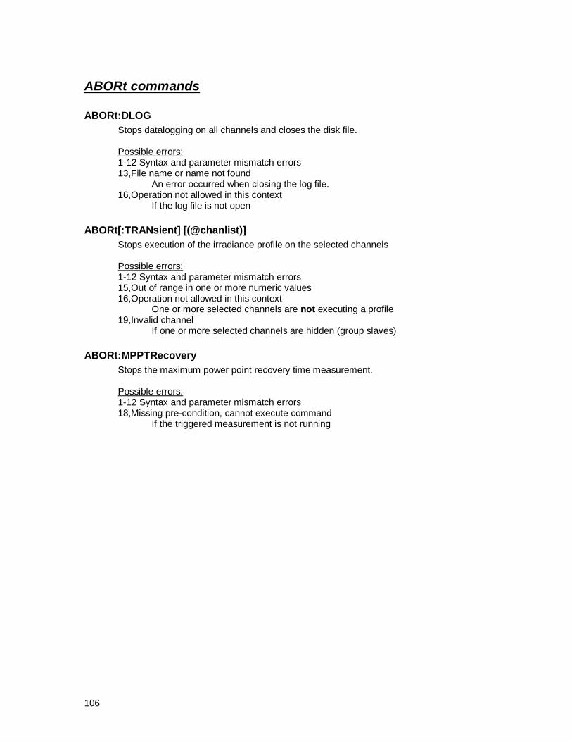
106
ABORt commands
ABORt:DLOG
Stops datalogging on all channels and closes the disk file.
Possible errors: 1-12 Syntax and parameter mismatch errors 13,File name or name not found An error occurred when closing the log file. 16,Operation not allowed in this context If the log file is not open
ABORt[:TRANsient] [(@chanlist)]
Stops execution of the irradiance profile on the selected channels
Possible errors: 1-12 Syntax and parameter mismatch errors 15,Out of range in one or more numeric values 16,Operation not allowed in this context One or more selected channels are not executing a profile 19,Invalid channel If one or more selected channels are hidden (group slaves)
ABORt:MPPTRecovery
Stops the maximum power point recovery time measurement.
Possible errors: 1-12 Syntax and parameter mismatch errors 18,Missing pre-condition, cannot execute command If the triggered measurement is not running

107
OUTPut subsystem
OUTPut[:STATe] {ON|OFF} [,(@chanlist)]
Turns on or off the output on the selected channels
Possible errors: 1-12 Syntax and parameter mismatch errors 15,Out of range in one or more numeric values 19,Invalid channel If one or more selected channels are hidden (group slaves)
OUTPut[:STATe]? [(@chanlist)]
Returns the output state of the selected channels. Multiple entries are separated by a comma. Possible errors: 1-12 Syntax and parameter mismatch errors 15,Out of range in one or more numeric values 19,Invalid channel If one or more selected channels are hidden (group slaves)
OUTPut:PROTection:CLEar [(@chanlist)]
Resets the overvoltage or overcurrent protection latch on the selected channels
Possible errors: 1-12 Syntax and parameter mismatch errors 15,Out of range in one or more numeric values 19,Invalid channel If one or more selected channels are hidden (group slaves)

108
Units of Measure
Units of Measure
Volts "NV" NanoVolt "UV" MicroVolt "MV" MilliVolt "V" Volt "KV" KiloVolt "MAV" MegaVolt Amperes "NA" NanoAmp "UA" MicroAmp "MA MilliAmp "A" Amp Ohms "UR MicroOhm "UOHM" MicroOhm (Note: no MilliOhms in SCPI - see MegaOhm) "R" Ohm "OHM" Ohm "KR" KiloOhm "KOHM" KiloOhm "MR" MegaOhm (in SCPI, MR=MAR=MegaOhm) "MAR" MegaOhm "MOHM" MegaOhm "MAOHM" MegaOhm "GR" GigaOhm "GOHM" GigaOhm Watts "NW" NanoWatt "UW" MicroWatt "MW" MilliWatt "W" Watt "KW" KiloWatt "MAW" MegaWatt "GW" GigaWatt Decibel Watts "DBNW" Decibel NanoWatt "DBUW" Decibel MicroWatt "DBM" Decibel MilliWatt "DBMW" Decibel MilliWatt "DBW" Decibel Watt Joules "UJ" MicroJoule "MJ" MilliJoule "J" Joule "KJ" KiloJoule Farads "PF" PicoFarad "NF" NanoFarad "UF" MicroFarad "MF" MilliFarad "F" Farad

109
Henrys "UH" MicroHenry "MH" MilliHenry "H" Henry Hertz "HZ" Hertz "KHZ" KiloHertz "MHZ" MegaHertz (in SCPI, MHZ=MAHZ=MegaHertz) "MAHZ" MegaHertz "GHZ" GigaHertz Seconds "PS" PicoSecond "NS" NanoSecond "US" MicroSecond "MS" MilliSecond "S" Second Temperature "K" Degree Kelvin "CEL" Degree Celsius "FAR" Degree Fahrenheit

110
SCPI Language Tutorial
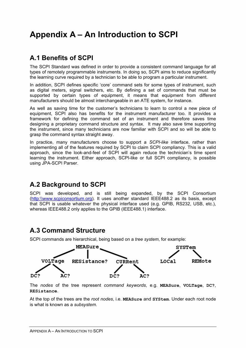
– AN INTRODUCTION TO SCPI
Appendix A – An Introduction to SCPI
A.1 Benefits of SCPI The SCPI Standard was defined in order to provide a consistent command language for all types of remotely programmable instruments. In doing so, SCPI aims to reduce significantly the learning curve required by a technician to be able to program a particular instrument. In addition, SCPI defines specific ‘core’ command sets for some types of instrument, such as digital meters, signal switchers, etc. By defining a set of commands that must be supported by certain types of equipment, it means that equipment from different manufacturers should be almost interchangeable in an ATE system, for instance. As well as saving time for the customer’s technicians to learn to control a new piece of equipment, SCPI also has benefits for the instrument manufacturer too. It provides a framework for defining the command set of an instrument and therefore saves time designing a proprietary command structure and syntax. It may also save time supporting the instrument, since many technicians are now familiar with SCPI and so will be able to grasp the command syntax straight away. In practice, many manufacturers choose to support a SCPI-like interface, rather than implementing all of the features required by SCPI to claim SCPI compliancy. This is a valid approach, since the look-and-feel of SCPI will again reduce the technician’s time spent learning the instrument. Either approach, SCPI-like or full SCPI compliancy, is possible using JPA-SCPI Parser.
A.2 Background to SCPI SCPI was developed, and is still being expanded, by the SCPI Consortium (http:\\www.scpiconsortium.org). It uses another standard IEEE488.2 as its basis, except that SCPI is usable whatever the physical interface used (e.g. GPIB, RS232, USB, etc.), whereas IEEE488.2 only applies to the GPIB (IEEE488.1) interface.
A.3 Command Structure SCPI commands are hierarchical, being based on a tree system, for example:
The nodes of the tree represent command keywords, e.g. MEASure, VOLTage, DC?, RESistance.
At the top of the trees are the root nodes, i.e. MEASure and SYStem. Under each root node is what is known as a subsystem.
APPENDIX A

A command is formed by traversing the tree from a root node downwards until a node is reached with no further nodes below it. Instead of drawing command trees, SCPI uses a notation to represent command specifications. When writing a command, the root node is written first, followed by the keywords on the lower levels. Colons (:) are used to separate keywords on different levels of the tree. For example:
MEASure:VOLTage:DC?
or: SYSTem:LOCal
In addition, SCPI notation represents the levels of the tree by the horizontal indentation of the keywords. The root node is in the leftmost position and so on. The commands represented by the diagram above would be written as:
MEASure :VOLTage :DC? :AC? :RESistance? :CURRent :DC? :AC?
SYSTem :LOCal :REMote
A.3.1 Long and Short Form Keywords You will see that many of the keywords above have upper and lowercase letters. This system is used to represent the long form and short form of each keyword. The long form of the keyword comprises all the characters of the keyword. The short form is made up of just the characters in uppercase.
For instance, for MEASure above:
• Long Form is MEASURE
• Short Form is MEAS
Usually, the short form of a keyword comprises the first four letters. However, if the fourth letter is a vowel, then the short form normally only uses the first 3 letters (e.g. CALibration).
Commands sent to a SCPI instrument can include any combination of long and short form keywords. For the command set above, all of these commands are valid:
MEASURE:VOLTAGE:DC?
MEAS:VOLT:DC?
MEASURE:VOLT:DC?
MEAS:VOLTAGE:DC?
JPA-SCPI PARSER – USER MANUAL

Note, that commands sent to a SCPI instrument are case-insensitive, for example, all of these are also valid commands:
Meas:Volt:DC?
measure:Voltage:dc?
By convention, however, example SCPI commands are usually shown in uppercase form. This is what we use in this manual.
A.3.2 Query Commands Any SCPI commands that expect data to be sent back over the remote interface are termed query commands. Such commands might request the voltage reading from a digital voltmeter, or request the identity of the instrument. All query commands end in a question mark. In the command set above, query commands include:
MEASure:VOLTage:DC?
MEASure:RESistance?
etc.
A.3.3 Default Keywords To shorten command entry, SCPI allows the use of default keywords (also known as default nodes). These are keywords that can be left out of commands without affecting the meaning of the command. Default keywords are shown in command specifications by enclosing them in square brackets. For example, the keywords of a command specification might be:
APPly:[SOURce:]CURRent[:LEVel][:IMMediate]:AMPLitude
In this case, valid forms of the command include: APPLY:SOURCE:CURRENT:LEVEL:IMMEDIATE:AMPLITUDE
APP:CURR:AMPL
APP:CURRENT:LEV:AMPLITUDE
etc. Notice how a colon can be included within the square brackets, in order that all possible command constructs will contain keywords separated by a single colon.
A.3.4 Numeric Suffices An instrument may have more than one outputs, trigger sources, etc. In order to specify which of these channels a command is referring to, a numeric suffix can be added to the command. For instance, a command to set the voltage range on a multi-channel oscilloscope might be specified as:
[SENSe:]VOLTage[:DC]<channel#>:RANGe {<voltage>|MIN|MAX}
To set channel 1 to 200mV range, the user might enter this command as:
VOLT1:RANG 200MV
To set channel 2 to 10V range, the user could enter this command:
SENS:VOLT2:RANG 10V
APPENDIX A – AN INTRODUCTION TO SCPI

In addition, if the user does not enter a numeric suffix, then the value 1 is assumed. So in this case, these two commands are equivalent, both setting channel 1 to the 2V range:
VOLT1:DC:RANG 2V
VOLT:DC:RANG 2V
Note, a command may have more than one numeric suffix. For example, this command might be used to set the 2nd FM signal component of the 3rd output channel:
OUTP3:FM2
A.3.5 Compound Commands It is possible to send compound commands to a SCPI instrument. Commands are separated within a command line by a semi-colon (;). For example:
MEAS:VOLT:DC?;AC?
Note that the second command is not the full command but rather it uses the command tree that was reached by the command before it. This shorthand is used by SCPI to reduce the length of command lines. If you need to use a command higher up the tree, then the second command must be prefixed by a colon (:). This has the effect of resetting the command tree to the root. The next command must therefore be in its full form, for example:
MEAS:VOLT:DC?;:MEAS:CURR:DC?
or:
MEAS:VOLT:DC?;:SYST:LOC
A.3.6 IEEE488.2 Common Commands SCPI-compliant instruments must support a small set of IEEE488.2 common commands defined in the IEEE488.2 standard. These include:
*RST
*CLS
IEEE488.2 common commands are used to reset the device, query its status registers, reset the interface etc. For more information on these commands, refer to the SCPI Standard and/or the IEEE488.2 Standard.
A.3.7 Parameters Many commands take one or more parameters in order to provide the instrument with more information, for example, the voltage level to set on a programmable power supply, or the resolution to use on a digital resistance meter. Parameters appear after the command keywords, separated from the keywords by a space (no spaces are allowed within the command keywords). If more than one parameter is allowed by the command, each parameter is separated by a comma. For example, a command might be sent as:
MEAS:VOLT? 1KV, 10MV
This would take a measurement from a digital voltmeter using a range of 1 kilovolts, and with a resolution of 10 millivolts. The parameters are 1KV and 10MV.
JPA-SCPI PARSER – USER MANUAL

A.3.8 Types of Parameter The different types of parameter allowed are:
A.3.8.1 Numeric Value This is a number with or without units. It could represent a voltage, a frequency, a count – anything that can be represented numerically. Numeric Values can also include units after the number. These are usually optional. In the example above, both 1KV and 10MV are Numeric Values.
A.3.8.1.1 Number Bases SCPI allows Numeric Values to be entered in some number bases other than decimal: binary, octal and hexadecimal. When entering a number in one of these other bases, the number must be prefixed to indicate the base.
Base Prefix Example Binary #B #B11001010 = 20210 Octal #Q #Q107 = 7110 Hexadecimal #H #H10FF = 435110
Note: Negative and real (non-integer) numbers are only allowable in decimal.
A.3.8.2 Boolean Sometimes, a parameter is required to set a state to on or off, e.g. auto-ranging on a digital meter can either be on or off. Parameters that just require two states are known as Booleans. Boolean parameters can be entered in a number of ways:
ON OFF
1 // same as entering ON 0 // same as entering OFF
In addition, SCPI allows entry of a number where a Boolean parameter is permitted. The number is converted to ON (1) or OFF (0) according to these rules:
• The sign of the number is ignored
• The number is rounded to the nearest integer, where .5 and above is rounded upwards
• If the resulting number is zero, the Boolean parameter is OFF (0). Otherwise the Boolean parameter is ON (1).
Boolean parameters can be specified with a default value, i.e. if the parameter is not entered it is equivalent to the parameter being entered with the default value. In SCPI notation, default values are shown in bold type (or you can use underline if bold type is not available). For example:
{ON|OFF}
Here, the default value is ON.
APPENDIX A – AN INTRODUCTION TO SCPI

A.3.8.3 Character Data SCPI also allows mnemonics to be entered as parameters. These are called Character Data parameters. For example, the command specification:
TRIGger:SOURce {BUS|IMMediate|EXTernal}
The possible values of the Character Data parameter are: BUS, IMM, IMMEDIATE, EXT or EXTERNAL.
In addition, Character Data choices are often combined with another type of parameter, e.g. a Numeric Value or Boolean parameter. For example, the specification of a command to set the resistance range of an ohmmeter might be:
SENSe:RESistance:RANGe {<range>|MINimum|MAXimum}
This command allows entries such as:
SENS:RES:RANG 1000
SENS:RES:RANG 1GOHM
SENS:RES:RANG MAX
SENS:RES:RANG MINIMUM
As with Boolean parameters, Character Data parameters can have a default value. For example:
{BUS|IMMediate|EXTernal}
Here, IMMediate is the default value used if the parameter is not entered.
A.3.8.4 String Occasionally, an instrument may wish to accept a parameter made up of a string of characters. For example, a command to display a text message on the instrument’s readout. Strings in SCPI must be delimited by quotes (either double or single). For instance, a command specification such as:
DISPlay:TEXT <message string>
would accept commands such as:
DISP:TEXT “hello world”
DISP:TEXT ‘Set function to “Volts”.’
In addition, JPA-SCPI Parser also supports a type we call Unquoted Strings. These function exactly the same as normal strings except that they do not require quotes to delimit them. Instead they are delimited by the commas (if any) that surround any parameter. Unquoted Strings are useful for entry of passwords, for instance, to allow access to calibration factors or maintenance functions. For example, the command specification:
CALibration:SECure:CODE <code>
would accept entries such as:
CAL:SEC:CODE ABC123
A.3.8.5 Expression SCPI defines various other types of parameter as expressions. These types include:
JPA-SCPI PARSER – USER MANUAL

• Numeric Expressions, e.g. (15*5+4)
• Numeric Lists, e.g. (1,2,3:7,9)
• Channel Lists, e.g. (@1!3,2!4:5!5)
• DIF (Data Interchange Format) Expressions All these types of expression start with an opening bracket (‘(‘) and end with a closing bracket (‘)‘). Support for expressions is optional in SCPI. In fact most instrument do not support them. DIF, for instance, is used for transferring large amounts of data from an instrument to a computer, so is useful for logging instruments etc. Numeric Lists and Channel Lists are amongst the most useful of the expressions, and these are explained further below.
A.3.8.6 Numeric List A numeric list is used to allow entry of a variable number of numeric values and ranges of numeric values. The format of a numeric list is:
(<entry>[,<entry>[,<entry>....]]])
where <entry> has the format: <numeric value>|<numeric value>:<numeric value>
Ranges are indicated by the first number in the range and last number in the range separated by a colon (:).
For example, a numeric list could be:
(5,7:17,20.5)
This numeric list has 3 entries: the value 5, the range 7 through to 17, and the value 20.5. Note, the order of entries in a numeric list does not matter – there is no order implied by the ordering of the entries in the numeric list.
A.3.8.7 Channel List A channel list is used to specify a set of electrical ports on an instrument. The most common use is for specifying signal routing and switching. The format of a channel list is:
(@<entry>[,<entry>[,<entry>....]]])
where <entry> has the format: <channel spec>|<channel spec>:<channel spec>
Ranges are indicated by the first number in the range and last number in the range separated by a colon (:).
In addition to allowing ranges of values just like numerical lists, channel list entries can have more than one dimension. A two dimensional entry comprises the value of the first dimension followed by a ‘!‘ symbol followed by the value of the second dimension.
The specification for <channel spec> is: <numeric value>[!<numeric value>[!<numeric value>....]]]
APPENDIX A – AN INTRODUCTION TO SCPI

For example, a channel spec could be:
3
or 5!6 or 4!7!9 The number of ! symbols is one less than the number of dimensions, so the last example above has 3 dimensions. Dimensions are useful for representing a matrix of switches, for example. Say you have 10 rows and 12 columns of switches. The 1st dimension represents the row number and the 2nd dimension represents the column number:
Column Row 1 2 3 4 5 6 7 8 9 10 11 12
1 1!1 1!2 1!3 1!4 1!5 1!6 1!7 1!8 1!9 1!10 1!11 1!12 2 2!1 2!2 2!3 2!4 2!5 2!6 2!7 2!8 2!9 2!10 2!11 2!12 3 3!1 3!2 3!3 3!4 3!5 3!6 3!7 3!8 3!9 3!10 3!11 3!12 4 4!1 4!2 4!3 4!4 4!5 4!6 4!7 4!8 4!9 4!10 4!11 4!12 5 5!1 5!2 5!3 5!4 5!5 5!6 5!7 5!8 5!9 5!10 5!11 5!12 6 6!1 6!2 6!3 6!4 6!5 6!6 6!7 6!8 6!9 6!10 6!11 6!12 7 7!1 7!2 7!3 7!4 7!5 7!6 7!7 7!8 7!9 7!10 7!11 7!12 8 8!1 8!2 8!3 8!4 8!5 8!6 8!7 8!8 8!9 8!10 8!11 8!12 9 9!1 9!2 9!3 9!4 9!5 9!6 9!7 9!8 9!9 9!10 9!11 9!12
10 10!1 10!2 10!3 10!4 10!5 10!6 10!7 10!8 10!9 10!10 10!11 10!12 A channel list to specify the switch at row 2, column 3 and row 9, column 11 would be:
(@2!3,9!11)
As mentioned above you can also specify ranges in a channel list. For a single dimensional channel list, this is exactly the same as a numeric list, e.g. for the range 5 through to 11, then channel list would be: (@5:11)
But what happens when you want to specify a range of values in a 2 dimensional, or multi-dimensional channel list? For instance, say we wanted to specify the switches in the table below that are shown with the grey background. We pick the first element in the group (3!3) and the last element (7!11) and separate them with a colon (:), i.e.:
3!3:7!11
This tells the instrument to operate on all the switches in the area marked. Not only that, but the order of operation is also implied by the order of the values in the range. In that example it means start at 3!3, then 3!4 and so on until 3!11. Now continue with 4!3 through to 4!11, and so on until 7!3 through to 7!11. If we wanted to operate in reverse order then we would simply reverse the order of the numbers, i.e.:
7!11:3!3
JPA-SCPI PARSER – USER MANUAL

Unlike a numeric list, the order of operation with entries in a channel list is implied by the order of the entries. For example:
(@1!3,2!5:3!1,4!4)
means operate in the following order: 1!3, 2!5, 2!4, 2!3, 2!2, 2!1, 3!5, 3!4, 3!3, 3!2, 3!1, 4!4
As well as numeric entries, SCPI allows channel lists to include alphanumeric entries such as module specifiers and path names. These are not very common in use and are beyond the scope of this introduction to SCPI. You may wish to refer to the SCPI Standard for more information.
APPENDIX A – AN INTRODUCTION TO SCPI