Embed Size (px)
Citation preview
Main catalogue Terminal blocks Explosive atmospheres protection
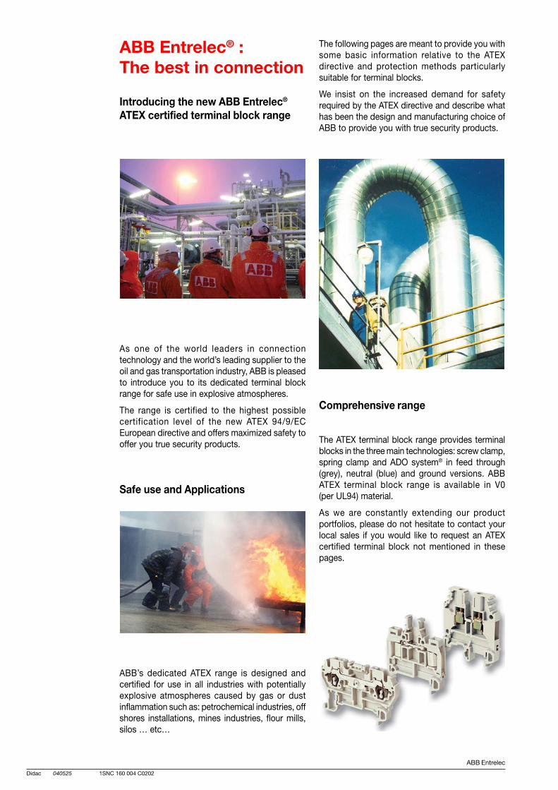
ABB Entrelec
Didac 040525 1SNC 160 004 C0202
ABB Entrelec® :The best in connection
Introducing the new ABB Entrelec®
ATEX certified terminal block range
As one of the world leaders in connectiontechnology and the world’s leading supplier to theoil and gas transportation industry, ABB is pleasedto introduce you to its dedicated terminal blockrange for safe use in explosive atmospheres.
The range is certified to the highest possiblecertification level of the new ATEX 94/9/ECEuropean directive and offers maximized safety tooffer you true security products.
Safe use and Applications
ABB’s dedicated ATEX range is designed andcertified for use in all industries with potentiallyexplosive atmospheres caused by gas or dustinflammation such as: petrochemical industries, offshores installations, mines industries, flour mills,silos … etc…
The following pages are meant to provide you withsome basic information relative to the ATEXdirective and protection methods particularlysuitable for terminal blocks.
We insist on the increased demand for safetyrequired by the ATEX directive and describe whathas been the design and manufacturing choice ofABB to provide you with true security products.
Comprehensive range
The ATEX terminal block range provides terminalblocks in the three main technologies: screw clamp,spring clamp and ADO system® in feed through(grey), neutral (blue) and ground versions. ABBATEX terminal block range is available in V0(per UL94) material.
As we are constantly extending our productportfolios, please do not hesitate to contact yourlocal sales if you would like to request an ATEXcertified terminal block not mentioned in thesepages.
1ABB Entrelec
Summary 040507 1SNC 160 004 C0202
Atex generalities
A. Explosive atmosphere ........................................................................... 2
B. European explosion directives ............................................................. 4
C. ATEX 94/9/EC conformity assessment procedures ........................... 8
D. Protection methods in potentially explosive atmosphere ............... 10
E. Product marking .................................................................................. 12
F. ABB Entrelec® terminal blocks & accessories certification ............. 13
Atex certified terminal blocks range
Summary ..................................................................................................... 15
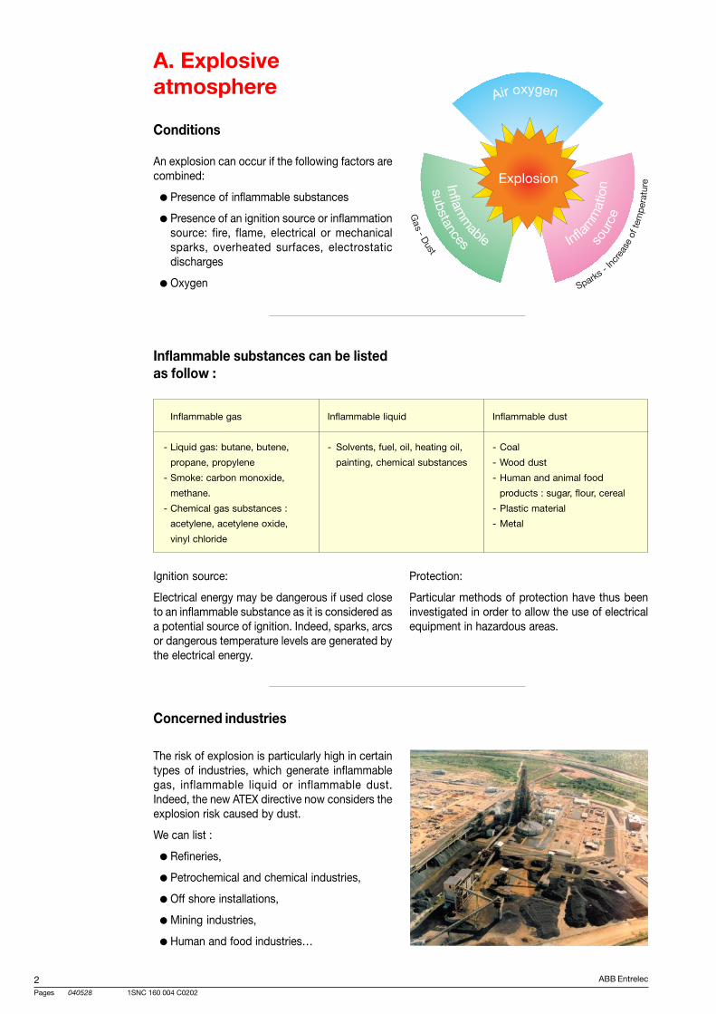
ABB Entrelec
Pages 040528
21SNC 160 004 C0202
A. Explosiveatmosphere
Concerned industries
The risk of explosion is particularly high in certaintypes of industries, which generate inflammablegas, inflammable liquid or inflammable dust.Indeed, the new ATEX directive now considers theexplosion risk caused by dust.
We can list :
Refineries,
Petrochemical and chemical industries,
Off shore installations,
Mining industries,
Human and food industries…
An explosion can occur if the following factors arecombined:
Presence of inflammable substances
Presence of an ignition source or inflammationsource: fire, flame, electrical or mechanicalsparks, overheated surfaces, electrostaticdischarges
Oxygen
Conditions
Inflammable substances can be listedas follow :
Inflammable gas Inflammable liquid Inflammable dust
- Liquid gas: butane, butene, - Solvents, fuel, oil, heating oil, - Coal
propane, propylene painting, chemical substances - Wood dust
- Smoke: carbon monoxide, - Human and animal food
methane. products : sugar, flour, cereal
- Chemical gas substances : - Plastic material
acetylene, acetylene oxide, - Metal
vinyl chloride
Ignition source:
Electrical energy may be dangerous if used closeto an inflammable substance as it is considered asa potential source of ignition. Indeed, sparks, arcsor dangerous temperature levels are generated bythe electrical energy.
Protection:
Particular methods of protection have thus beeninvestigated in order to allow the use of electricalequipment in hazardous areas.
ABB Entrelec
Pages 040528
31SNC 160 004 C0202
Industries Risks
Refineries Treatment of hydrocarbon highly inflammable
Petrochemical and chemical industries Transformation and treatment processes which can generateexplosive mixing
Pharmaceutical and cosmetic industries Use of alcohol highly inflammable like solventsUse of active material or adjuvant which can create explosive dust
Waste and water recycling industries Paper or plastic dustStorage of barrels or containers partially or not emptiedGas fermentation emission during water treatment
Painting facilities Over spray formation during the lacquering of surfaces with spraygun
Gas distribution Gas/ air mixing creation if gas leaking
Human and animal food industries Transport and stocking of cereal, powder… which can createpotentially dust explosive atmospheres in filters and aerators
Wood saw mills, metal machining Metal dust generation during metal polishing which can create dustexplosive atmospheres in collectors
The risk can be expressed as follow :
ABB Entrelec
Pages 040528
41SNC 160 004 C0202
B. European explosiondirectives
ATEX European directive consists in two parts :
ATEX 94/9/EC (generally called ATEX 95), whichconcentrates on the duties of themanufacturers.
ATEX 1999/92/EC (generally called ATEX 137),which focuses on the end users obligations.
The objectives of the directives
“Minimum requirements” is a key phrase of thedirectives - member states are free to introducemore stringent measures if they wish.
ATEX belongs to the group of the so-called “newapproach” directives.
Under a new approach directive, any route towardsachieving the objective is permitted.
The European commission will not interfere withhow a technical solution is reached, but gives allparties involved the freedom to define the bestmeans, methods and procedures to meet theguidelines.
This gives rise to a division of responsibilitiesbetween the equipment manufacturer and the enduser.
The less responsibility the equipment manufacturerassumes for achieving the solution, the more theend user will have to take on, and vice versa.
Directive applicable to ABBEntrelec "terrminal blocks"
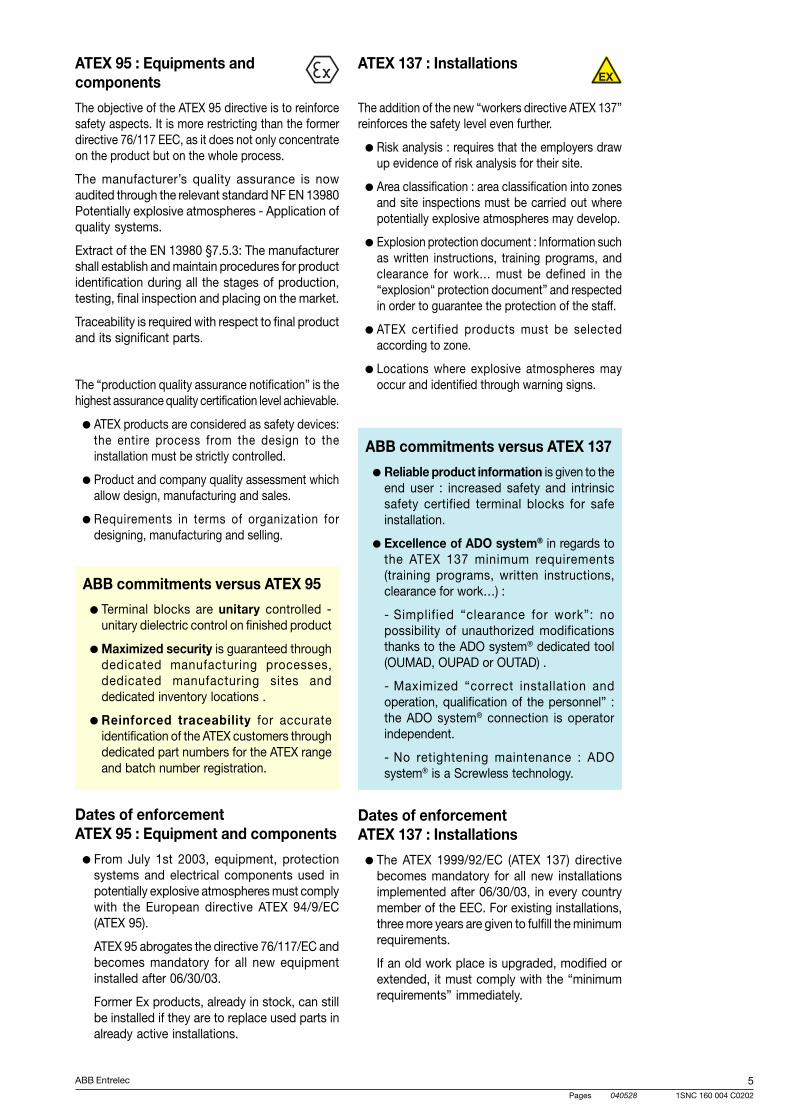
ABB Entrelec
Pages 040528
51SNC 160 004 C0202
Dates of enforcementATEX 95 : Equipment and components
From July 1st 2003, equipment, protectionsystems and electrical components used inpotentially explosive atmospheres must complywith the European directive ATEX 94/9/EC(ATEX 95).
ATEX 95 abrogates the directive 76/117/EC andbecomes mandatory for all new equipmentinstalled after 06/30/03.
Former Ex products, already in stock, can stillbe installed if they are to replace used parts inalready active installations.
ATEX 137 : Installations
The addition of the new “workers directive ATEX 137”reinforces the safety level even further.
Risk analysis : requires that the employers drawup evidence of risk analysis for their site.
Area classification : area classification into zonesand site inspections must be carried out wherepotentially explosive atmospheres may develop.
Explosion protection document : Information suchas written instructions, training programs, andclearance for work… must be defined in the“explosion“ protection document” and respectedin order to guarantee the protection of the staff.
ATEX certified products must be selectedaccording to zone.
Locations where explosive atmospheres mayoccur and identified through warning signs.
ATEX 95 : Equipments andcomponents
The objective of the ATEX 95 directive is to reinforcesafety aspects. It is more restricting than the formerdirective 76/117 EEC, as it does not only concentrateon the product but on the whole process.
The manufacturer’s quality assurance is nowaudited through the relevant standard NF EN 13980Potentially explosive atmospheres - Application ofquality systems.
Extract of the EN 13980 §7.5.3: The manufacturershall establish and maintain procedures for productidentification during all the stages of production,testing, final inspection and placing on the market.
Traceability is required with respect to final productand its significant parts.
The “production quality assurance notification” is thehighest assurance quality certification level achievable.
ATEX products are considered as safety devices:the entire process from the design to theinstallation must be strictly controlled.
Product and company quality assessment whichallow design, manufacturing and sales.
Requirements in terms of organization fordesigning, manufacturing and selling.
ABB commitments versus ATEX 95
Terminal blocks are unitary controlled -unitary dielectric control on finished product
Maximized security is guaranteed throughdedicated manufacturing processes,dedicated manufacturing sites anddedicated inventory locations .
Reinforced traceability for accurateidentification of the ATEX customers throughdedicated part numbers for the ATEX rangeand batch number registration.
Dates of enforcementATEX 137 : Installations
The ATEX 1999/92/EC (ATEX 137) directivebecomes mandatory for all new installationsimplemented after 06/30/03, in every countrymember of the EEC. For existing installations,three more years are given to fulfill the minimumrequirements.
If an old work place is upgraded, modified orextended, it must comply with the “minimumrequirements” immediately.
ABB commitments versus ATEX 137
Reliable product information is given to theend user : increased safety and intrinsicsafety certified terminal blocks for safeinstallation.
Excellence of ADO system® in regards tothe ATEX 137 minimum requirements(training programs, written instructions,clearance for work…) :
- Simplified “clearance for work”: nopossibility of unauthorized modificationsthanks to the ADO system® dedicated tool(OUMAD, OUPAD or OUTAD) .
- Maximized “correct installation andoperation, qualification of the personnel” :the ADO system® connection is operatorindependent.
- No retightening maintenance : ADOsystem® is a Screwless technology.
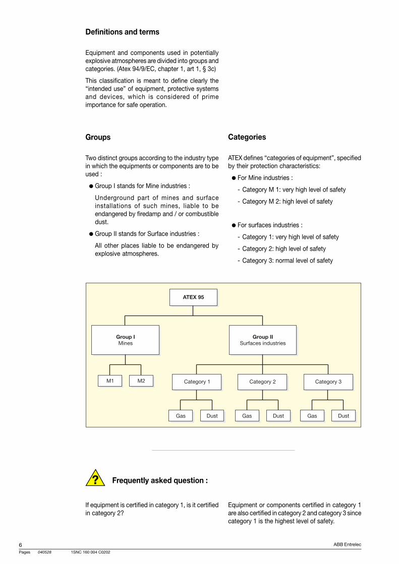
ABB Entrelec
Pages 040528
61SNC 160 004 C0202
?
Definitions and terms
Equipment and components used in potentiallyexplosive atmospheres are divided into groups andcategories. (Atex 94/9/EC, chapter 1, art 1, § 3c)
This classification is meant to define clearly the“intended use” of equipment, protective systemsand devices, which is considered of primeimportance for safe operation.
Groups
Two distinct groups according to the industry typein which the equipments or components are to beused :
Group I stands for Mine industries :
Underground part of mines and surfaceinstallations of such mines, liable to beendangered by firedamp and / or combustibledust.
Group II stands for Surface industries :
All other places liable to be endangered byexplosive atmospheres.
Frequently asked question :
If equipment is certified in category 1, is it certifiedin category 2?
Equipment or components certified in category 1are also certified in category 2 and category 3 sincecategory 1 is the highest level of safety.
Categories
ATEX defines “categories of equipment”, specifiedby their protection characteristics:
For Mine industries :
- Category M 1: very high level of safety
- Category M 2: high level of safety
For surfaces industries :
- Category 1: very high level of safety
- Category 2: high level of safety
- Category 3: normal level of safety
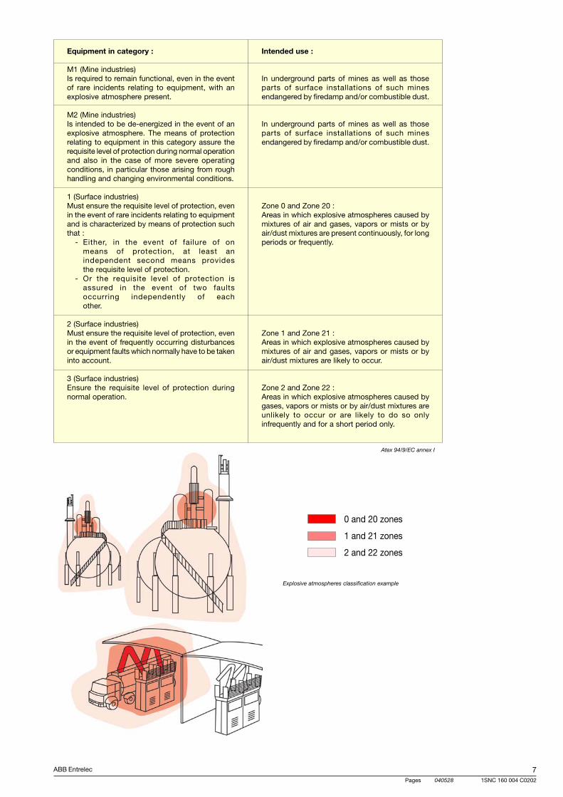
ABB Entrelec
Pages 040528
71SNC 160 004 C0202
Equipment in category :
M1 (Mine industries)Is required to remain functional, even in the eventof rare incidents relating to equipment, with anexplosive atmosphere present.
M2 (Mine industries)Is intended to be de-energized in the event of anexplosive atmosphere. The means of protectionrelating to equipment in this category assure therequisite level of protection during normal operationand also in the case of more severe operatingconditions, in particular those arising from roughhandling and changing environmental conditions.
1 (Surface industries)Must ensure the requisite level of protection, evenin the event of rare incidents relating to equipmentand is characterized by means of protection suchthat :
- Either, in the event of failure of onmeans of protection, at least anindependent second means providesthe requisite level of protection.
- Or the requisite level of protection isassured in the event of two faultsoccurring independently of eachother.
2 (Surface industries)Must ensure the requisite level of protection, evenin the event of frequently occurring disturbancesor equipment faults which normally have to be takeninto account.
3 (Surface industries)Ensure the requisite level of protection duringnormal operation.
Intended use :
In underground parts of mines as well as thoseparts of surface installations of such minesendangered by firedamp and/or combustible dust.
In underground parts of mines as well as thoseparts of surface installations of such minesendangered by firedamp and/or combustible dust.
Zone 0 and Zone 20 :Areas in which explosive atmospheres caused bymixtures of air and gases, vapors or mists or byair/dust mixtures are present continuously, for longperiods or frequently.
Zone 1 and Zone 21 :Areas in which explosive atmospheres caused bymixtures of air and gases, vapors or mists or byair/dust mixtures are likely to occur.
Zone 2 and Zone 22 :Areas in which explosive atmospheres caused bygases, vapors or mists or by air/dust mixtures areunlikely to occur or are likely to do so onlyinfrequently and for a short period only.
0 and 20 zones
1 and 21 zones
2 and 22 zones
Explosive atmospheres classification example
Atex 94/9/EC annex I
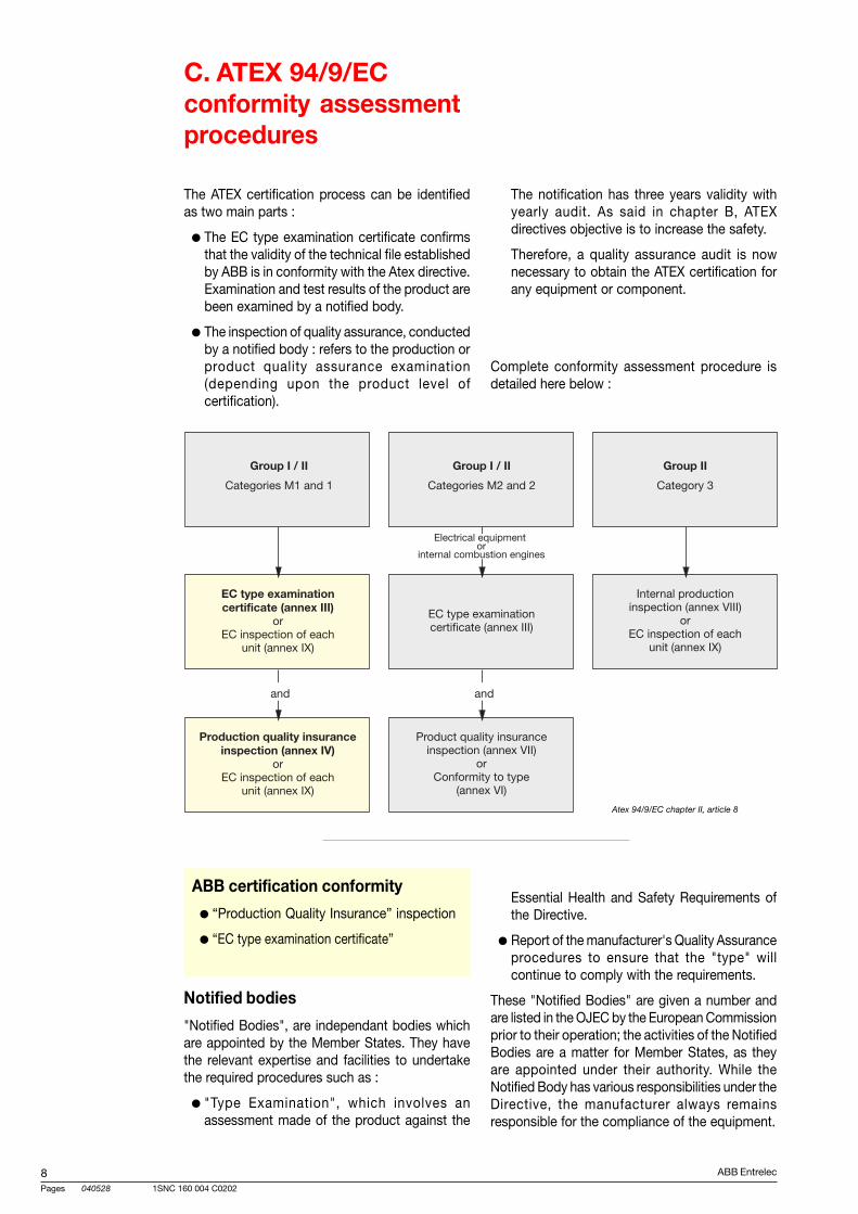
ABB Entrelec
Pages 040528
81SNC 160 004 C0202
C. ATEX 94/9/ECconformity assessmentprocedures
The ATEX certification process can be identifiedas two main parts :
The EC type examination certificate confirmsthat the validity of the technical file establishedby ABB is in conformity with the Atex directive.Examination and test results of the product arebeen examined by a notified body.
The inspection of quality assurance, conductedby a notified body : refers to the production orproduct quality assurance examination(depending upon the product level ofcertification).
Essential Health and Safety Requirements ofthe Directive.
Report of the manufacturer's Quality Assuranceprocedures to ensure that the "type" willcontinue to comply with the requirements.
These "Notified Bodies" are given a number andare listed in the OJEC by the European Commissionprior to their operation; the activities of the NotifiedBodies are a matter for Member States, as theyare appointed under their authority. While theNotified Body has various responsibilities under theDirective, the manufacturer always remainsresponsible for the compliance of the equipment.
The notification has three years validity withyearly audit. As said in chapter B, ATEXdirectives objective is to increase the safety.
Therefore, a quality assurance audit is nownecessary to obtain the ATEX certification forany equipment or component.
Complete conformity assessment procedure isdetailed here below :
Notified bodies
"Notified Bodies", are independant bodies whichare appointed by the Member States. They havethe relevant expertise and facilities to undertakethe required procedures such as :
"Type Examination", which involves anassessment made of the product against the
ABB certification conformity
“Production Quality Insurance” inspection
“EC type examination certificate”
Atex 94/9/EC chapter II, article 8
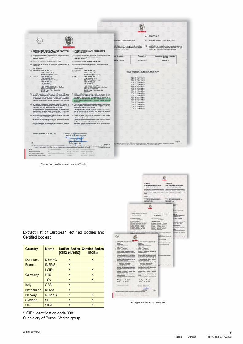
ABB Entrelec
Pages 040528
91SNC 160 004 C0202
Production quality assessment notification
Extract list of European Notified bodies andCertified bodies :
Country Name Notified Bodies Certified Bodies(ATEX 94/4/EC) (IECEx)
Denmark DEMKO X X
France INERIS X
LCIE* X X
Germany PTB X X
TÜV X X
Italy CESI X
Netherland KEMA X
Norway NEMKO X X
Sweden SP X X
UK SIRA X X
*LCIE : identification code 0081Subsidiary of Bureau Veritas group
EC type examination certificate
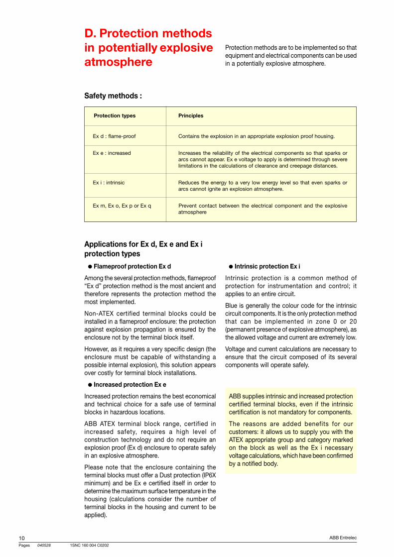
ABB Entrelec
Pages 040528
101SNC 160 004 C0202
D. Protection methodsin potentially explosiveatmosphere
Protection methods are to be implemented so thatequipment and electrical components can be usedin a potentially explosive atmosphere.
Applications for Ex d, Ex e and Ex iprotection types
Flameproof protection Ex d
Among the several protection methods, flameproof“Ex d” protection method is the most ancient andtherefore represents the protection method themost implemented.
Non-ATEX certified terminal blocks could beinstalled in a flameproof enclosure: the protectionagainst explosion propagation is ensured by theenclosure not by the terminal block itself.
However, as it requires a very specific design (theenclosure must be capable of withstanding apossible internal explosion), this solution appearsover costly for terminal block installations.
Increased protection Ex e
Increased protection remains the best economicaland technical choice for a safe use of terminalblocks in hazardous locations.
ABB ATEX terminal block range, certified inincreased safety, requires a high level ofconstruction technology and do not require anexplosion proof (Ex d) enclosure to operate safelyin an explosive atmosphere.
Please note that the enclosure containing theterminal blocks must offer a Dust protection (IP6Xminimum) and be Ex e certified itself in order todetermine the maximum surface temperature in thehousing (calculations consider the number ofterminal blocks in the housing and current to beapplied).
Intrinsic protection Ex i
Intrinsic protection is a common method ofprotection for instrumentation and control; itapplies to an entire circuit.
Blue is generally the colour code for the intrinsiccircuit components. It is the only protection methodthat can be implemented in zone 0 or 20(permanent presence of explosive atmosphere), asthe allowed voltage and current are extremely low.
Voltage and current calculations are necessary toensure that the circuit composed of its severalcomponents will operate safely.
Safety methods :
Protection types Principles
Ex d : flame-proof Contains the explosion in an appropriate explosion proof housing.
Ex e : increased Increases the reliability of the electrical components so that sparks orarcs cannot appear. Ex e voltage to apply is determined through severelimitations in the calculations of clearance and creepage distances.
Ex i : intrinsic Reduces the energy to a very low energy level so that even sparks orarcs cannot ignite an explosion atmosphere.
Ex m, Ex o, Ex p or Ex q Prevent contact between the electrical component and the explosiveatmosphere
ABB supplies intrinsic and increased protectioncertified terminal blocks, even if the intrinsiccertification is not mandatory for components.
The reasons are added benefits for ourcustomers: it allows us to supply you with theATEX appropriate group and category markedon the block as well as the Ex i necessaryvoltage calculations, which have been confirmedby a notified body.
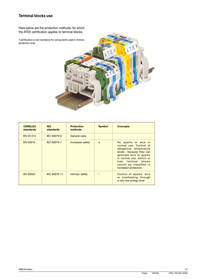
ABB Entrelec
Pages 040528
111SNC 160 004 C0202
CENELEC IEC Protection Symbol Conceptsstandards standards methods
EN 50 014 IEC 60079-0 General rules
EN 50019 IEC 60079-7 Increased safety e No sparks or arcs innormal use. Control ofdangerous temperaturelevels : because they cangenerate arcs or sparksin normal use, switch orfuse terminal blockscannot be classified inincreased protection.
EN 50020 IEC 60079-11 Intrinsic safety i Control of sparks, arcsor overheating througha very low energy level
Terminal blocks use
Here below are the protection methods, for whichthe ATEX certification applies to terminal blocks.
(*certification is not mandatory for components used in intrinsicprotection only)
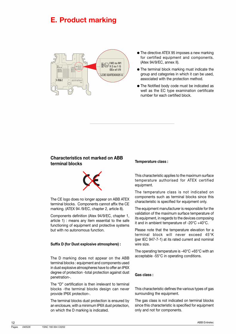
ABB Entrelec
Pages 040528
121SNC 160 004 C0202
Characteristics not marked on ABBterminal blocks
The CE logo does no longer appear on ABB ATEXterminal blocks. Components cannot affix the CEmarking. (ATEX 94 /9/EC, chapter 2, article 8).
Components definition (Atex 94/9/EC, chapter 1,article 1) : means any item essential to the safefunctioning of equipment and protective systemsbut with no autonomous function.
Suffix D (for Dust explosive atmosphere) :
The D marking does not appear on the ABBterminal blocks : equipment and components usedin dust explosive atmospheres have to offer an IP6Xdegree of protection -total protection against dustpenetration-.
The “D” certification is then irrelevant to terminalblocks -the terminal blocks design can neverprovide IP6X protection-.
The terminal blocks dust protection is ensured byan enclosure, with a minimum IP6X dust protection,on which the D marking is indicated.
Temperature class :
This characteristic applies to the maximum surfacetemperature authorised for ATEX certifiedequipment.
The temperature class is not indicated oncomponents such as terminal blocks since thischaracteristic is specified for equipment only.
The equipment manufacturer is responsible for thevalidation of the maximum surface temperature ofits equipment, in regards to the devices composingit and in ambient temperature of -20°C +40°C.
Please note that the temperature elevation for aterminal block will never exceed 45°K(per IEC 947-7-1) at its rated current and nominalwire size.
The operating temperature is -40°C +65°C with anacceptable -55°C in operating conditions.
Gas class :
This characteristic defines the various types of gassurrounding the equipment.
The gas class is not indicated on terminal blockssince this characteristic is specified for equipmentonly and not for components.
The directive ATEX 95 imposes a new markingfor certified equipment and components.(Atex 94/9/EC, annex II).
The terminal block marking must indicate thegroup and categories in which it can be used,associated with the protection method.
The Notified body code must be indicated aswell as the EC type examination certificatenumber for each certified block.
E. Product marking
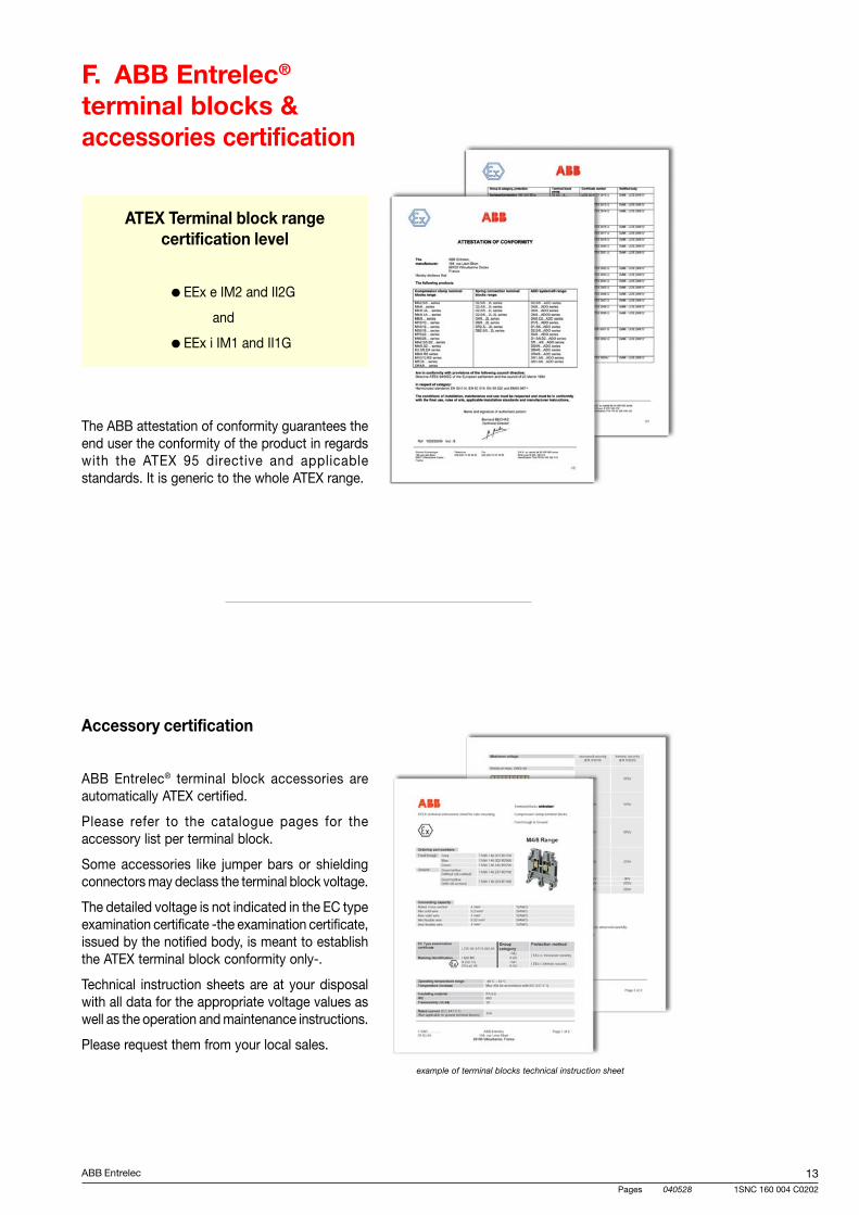
ABB Entrelec
Pages 040528
131SNC 160 004 C0202
F. ABB Entrelec®
terminal blocks &accessories certification
ATEX Terminal block rangecertification level
EEx e IM2 and II2G
and
EEx i IM1 and II1G
Accessory certification
ABB Entrelec® terminal block accessories areautomatically ATEX certified.
Please refer to the catalogue pages for theaccessory list per terminal block.
Some accessories like jumper bars or shieldingconnectors may declass the terminal block voltage.
The detailed voltage is not indicated in the EC typeexamination certificate -the examination certificate,issued by the notified body, is meant to establishthe ATEX terminal block conformity only-.
Technical instruction sheets are at your disposalwith all data for the appropriate voltage values aswell as the operation and maintenance instructions.
Please request them from your local sales.
example of terminal blocks technical instruction sheet
The ABB attestation of conformity guarantees theend user the conformity of the product in regardswith the ATEX 95 directive and applicablestandards. It is generic to the whole ATEX range.
ABB Entrelec
Pages 040528
141SNC 160 004 C0202
Ex e : increased safety protection method
II : stands for gas group (IIA, IIB, and IIC)
T6 (Temperature classification) : T ≤ 85°C (185°F)
Please refer to the appropriate UL file for conditionsof use and ratings values to apply.
G. Terminal blocks ULHazardous Locationscertification
References :
http://europa.en.int/comm/enterprise/atex
Directive 94/9/EC
Guidelines on the application of directive 94/9/EC
Corrigendum of directive 94/9/EC
Directive 1999/92/EC
http://www.ul.com/hazloc
http://www.offshore-technology.com
UL hazardous locations definitionsand terms :
Class I Zone 1 :
- Location in which ignitable concentrations offlammable gases or vapors are likely to exist undernormal operating conditions ; or
- Location in which ignitable concentrations offlammable gases or vapors may exist frequentlybecause of repair or maintenance operations orbecause of leakage ; or
- Location in which equipment is operated orprocesses are carried on, of such a nature thatequipment breakdown or faulty operations couldresult in the release of ignitable concentrations offlammable gases or vapors and also causesimultaneous failure of electrical equipment in amode to cause the electrical equipment to becomea source of ignition ; or
- That is adjacent to a Class 1, Zone 0 locationfrom which ignitable concentrations of vaporscould be communicated, unless communication isprevented by adequate positive pressure ventilationfrom a source of clean air and effective safeguardsagainst ventilation failure are provided.
UL Hazardous locations terminal block range certification level :
Class I Zone 1 Ex e II T6
(Partial range, indicated by * in the products pages)
15ABB Entrelec
T07102 040528
D
1
1SNC 160 004 C0202
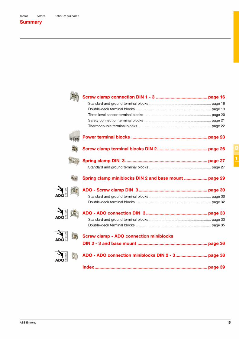
Screw clamp connection DIN 1 - 3 .......................................... page 16Standard and ground terminal blocks ............................................................. page 16
Double-deck terminal blocks ........................................................................... page 19
Three level sensor terminal blocks .................................................................. page 20
Safety connection terminal blocks .................................................................. page 21
Thermocouple terminal blocks ........................................................................ page 22
Power terminal blocks .............................................................. page 23
Screw clamp terminal blocks DIN 2......................................... page 26
Spring clamp DIN 3 ................................................................... page 27Standard and ground terminal blocks ............................................................. page 27
Spring clamp miniblocks DIN 2 and base mount ................... page 29
ADO - Screw clamp DIN 3 ........................................................ page 30Standard and ground terminal blocks ............................................................. page 30
Double-deck terminal blocks ........................................................................... page 32
ADO - ADO connection DIN 3 .................................................. page 33Standard and ground terminal blocks ............................................................. page 33
Double-deck terminal blocks ........................................................................... page 35
Screw clamp - ADO connection miniblocks
DIN 2 - 3 and base mount ......................................................... page 36
ADO - ADO connection miniblocks DIN 2 - 3.......................... page 38
Index ............................................................................................ page 39
Summary
16 ABB Entrelec
T07074 040525
D
1
1SNC 160 004 C0202
IEC UL CSANFC DIN
MA 2,5/5...Ex
MA 2,5/5.P.Ex
MA 2,5/5.Ex*MA 2,5/5.N.Ex*
MA 2,5/5.PI.ExMA 2,5/5.P.Ex*
RC 55 - RC510
10
1
4
5
2
3
8
6
7
12
14
10 mm / .39"0.4-0.6 Nm / 3.5-5.3 Ib-in
2.5 mm2 12 AWG 12 AWG300 A / 1 s
0.2 - 422-12 AWG 22-12 AWG
0.22 - 2.5
R
13
9
FEM6 V0 •FEM6 V0 •FEM6 V0 •FEM6 •FEM6 •FEM6 V0 •SCMA5SCF6SCFM6AL2 (1)
DCB •FC2 •BJMI5 (1) •BJMI5 (1) •BJMI5 (1) •BJMI5 (1) •BJMI5 (1) •EL6 •BJS5 (1)EV5 •BJE •
PC5 (3) •EIP •CBM5 •CBM8 •
11
EExe : 750 V EExi : 90 VEEx : 24 A
I M2 / M1 II 2G / 1GEEx e/i I / II
LCIE 02 ATEX 0025U
IEC UL CSANFC DIN
M 4/6...Ex
M 4/6.P.Ex
M 4/6.Ex*M 4/6.N.Ex*M 4/6.Ex
M 4/6.PI.ExM 4/6.P.Ex
RC 65 - RC610
9.5 mm / .37"0.5-0.8 Nm / 4.4-7.1 Ib-in
4 mm2 10 AWG 10 AWG480 A / 1 s
0.2 - 4 22-10 AWG22-10AWG
0.22 - 4 24-12 AWG (M 4/6.P.Ex)
FEM6 V0 •FEM6 V0 •FEM6 V0FEM6 •FEM6 •FEM6 V0SCM6 •SCF6SCFM6AL2 (1) •AL3 (1) •
DCJ •FC2 •BJMI6 (1) •BJMI6 (1) •BJMI6 (1) •BJMI6 (1) •BJMI6 (1) •EL6 •BJS6 (1) •EV6 •BJE •
PC6 (3) •EIP •CBM5 •CBM8 •
EP6 •VSP6 •
M 4/6.3A...Ex
M 4/6.4A...Ex
M 4/6.3A.ExM 4/6.3A.N.ExM 4/6.4A.ExM 4/6.4A.N.Ex
RC 65 - RC610
9.5 mm / .37"0.5-0.8 Nm / 4.4-7.1 Ib-in
0.2 - 422-10AWG 22-10AWG
0.22 - 4
FEM3A V0 (4)FEM3A (4)FEM4A V0 (5)FEM4A (5)
SCM6 •
AL2 (1) •AL3 (1) •
DCJ •FC2 •BJMI6 (1) •BJMI6 (1) •BJMI6 (1) •BJMI6 (1) •BJMI6 (1) •EL6 •BJS6 (1) •EV6 •BJE •
PC6 (3)EIP
IEC UL CSANFC DIN
EExe : 750 V EExi : 375 VEEx : 32 A
I M2 / M1 II 2G / 1GEEx e/i I / II
LCIE 02 ATEX 0014U
EExe : 420 V EExi : 190 VEEx : 32 A
I M2 / M1 II 2G / 1GEEx e/i I / II
LCIE 02 ATEX 0028U
4 mm2 10 AWG 12 AWG
Spacing 5 mm .200"
Spacing 5 mm .200"
Standard 5 mm block
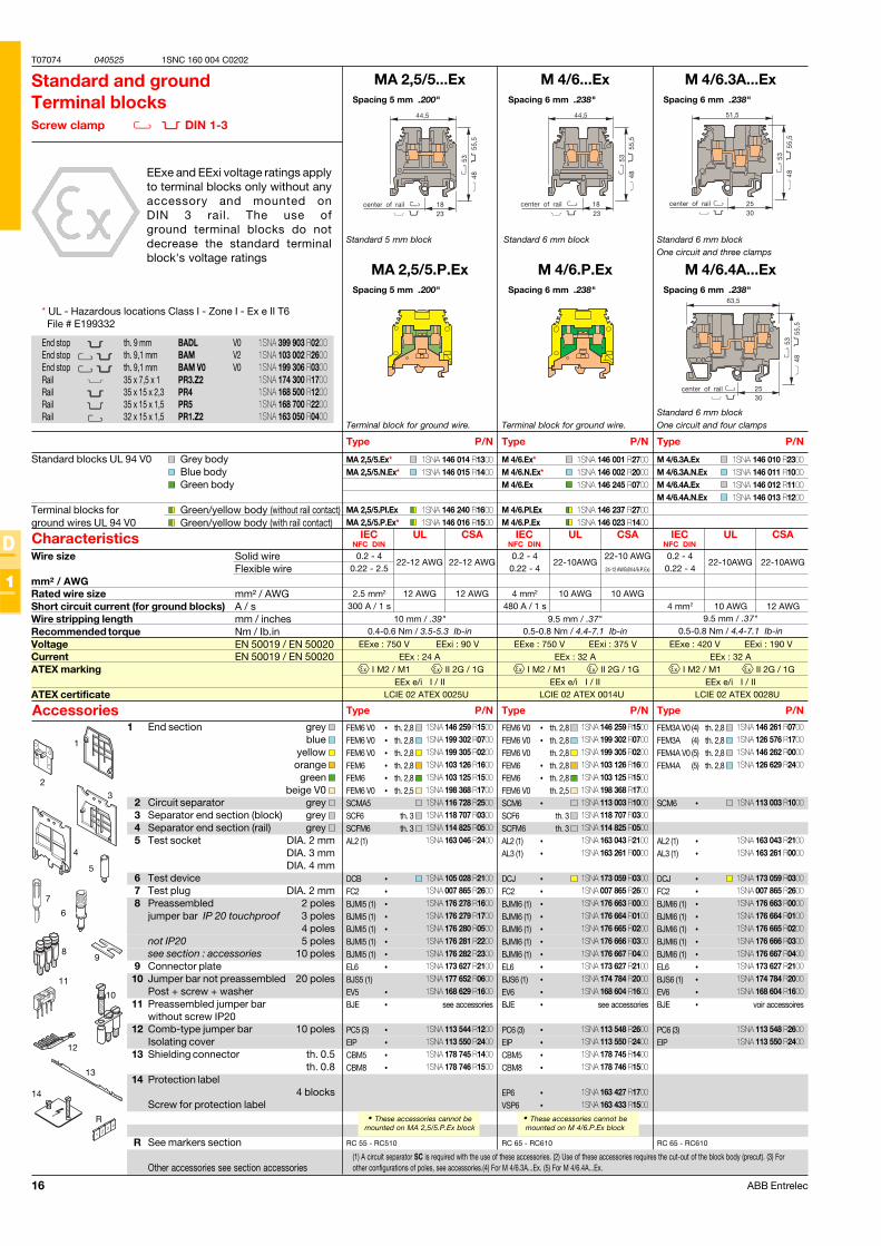
Standard and groundTerminal blocksScrew clamp DIN 1-3
EExe and EExi voltage ratings applyto terminal blocks only without anyaccessory and mounted onDIN 3 rail. The use ofground terminal blocks do notdecrease the standard terminalblock's voltage ratings
Terminal block for ground wire.
(1) A circuit separator SC is required with the use of these accessories. (2) Use of these accessories requires the cut-out of the block body (precut). (3) Forother configurations of poles, see accessories.(4) For M 4/6.3A...Ex. (5) For M 4/6.4A...Ex.
• These accessories cannot bemounted on MA 2,5/5.P.Ex block
1 End section grey blue
yellow orange
green beige V0
2 Circuit separator grey 3 Separator end section (block) grey 4 Separator end section (rail) grey 5 Test socket DIA. 2 mm
DIA. 3 mmDIA. 4 mm
6 Test device7 Test plug DIA. 2 mm8 Preassembled 2 poles
jumper bar IP 20 touchproof 3 poles4 poles
not IP20 5 polessee section : accessories 10 poles
9 Connector plate10 Jumper bar not preassembled 20 poles
Post + screw + washer11 Preassembled jumper bar
without screw IP2012 Comb-type jumper bar 10 poles
Isolating cover13 Shielding connector th. 0.5
th. 0.814 Protection label
4 blocksScrew for protection label
R See markers section
Other accessories see section accessories
Type P/N
Standard blocks UL 94 V0 Grey bodyBlue bodyGreen body
Terminal blocks for Green/yellow body (without rail contact)ground wires UL 94 V0 Green/yellow body (with rail contact)
Characteristics
Type P/NAccessories
End stop th. 9 mm BADL V0End stop th. 9,1 mm BAM V2End stop th. 9,1 mm BAM V0 V0Rail 35 x 7,5 x 1 PR3.Z2Rail 35 x 15 x 2,3 PR4Rail 35 x 15 x 1,5 PR5Rail 32 x 15 x 1,5 PR1.Z2
Wire size Solid wireFlexible wire
mm² / AWGRated wire size mm² / AWGShort circuit current (for ground blocks) A / sWire stripping length mm / inchesRecommended torque Nm / Ib.inVoltage EN 50019 / EN 50020Current EN 50019 / EN 50020ATEX marking
ATEX certificate
Spacing 6 mm .238"
Spacing 6 mm .238"
Standard 6 mm block
Terminal block for ground wire.
• These accessories cannot bemounted on M 4/6.P.Ex block
Type P/N
Type P/N
Spacing 6 mm .238"
Spacing 6 mm .238"
Standard 6 mm blockOne circuit and three clamps
Standard 6 mm blockOne circuit and four clamps
Type P/N
Type P/N
th. 2,8 th. 2,8 th. 2,8 th. 2,8 th. 2,8 th. 2,5
th. 3 th. 3
see accessories
th. 2,8 th. 2,8 th. 2,8 th. 2,8 th. 2,8 th. 2,5
th. 3 th. 3
see accessories
th. 2,8 th. 2,8 th. 2,8 th. 2,8
voir accessoires
* UL - Hazardous locations Class I - Zone I - Ex e II T6 File # E199332
1SNA 399 903 R02001SNA 103 002 R26001SNA 199 306 R03001SNA 174 300 R17001SNA 168 500 R12001SNA 168 700 R22001SNA 163 050 R0400
1SNA 146 014 R13001SNA 146 015 R1400
1SNA 146 240 R16001SNA 146 016 R1500
1SNA 146 001 R27001SNA 146 002 R20001SNA 146 245 R0700
1SNA 146 237 R27001SNA 146 023 R1400
1SNA 146 259 R15001SNA 199 302 R07001SNA 199 305 R02001SNA 103 126 R16001SNA 103 125 R15001SNA 198 368 R17001SNA 116 728 R25001SNA 118 707 R03001SNA 114 825 R05001SNA 163 046 R2400
1SNA 105 028 R21001SNA 007 865 R26001SNA 176 278 R16001SNA 176 279 R17001SNA 176 280 R05001SNA 176 281 R22001SNA 176 282 R23001SNA 173 627 R21001SNA 177 652 R06001SNA 168 629 R1600
1SNA 113 544 R12001SNA 113 550 R24001SNA 178 745 R14001SNA 178 746 R1500
1SNA 146 259 R15001SNA 199 302 R07001SNA 199 305 R02001SNA 103 126 R16001SNA 103 125 R15001SNA 198 368 R17001SNA 113 003 R10001SNA 118 707 R03001SNA 114 825 R05001SNA 163 043 R21001SNA 163 261 R0000
1SNA 173 059 R03001SNA 007 865 R26001SNA 176 663 R00001SNA 176 664 R01001SNA 176 665 R02001SNA 176 666 R03001SNA 176 667 R04001SNA 173 627 R21001SNA 174 784 R20001SNA 168 604 R1600
1SNA 113 548 R26001SNA 113 550 R24001SNA 178 745 R14001SNA 178 746 R1500
1SNA 163 427 R17001SNA 163 433 R1500
1SNA 146 010 R23001SNA 146 011 R10001SNA 146 012 R11001SNA 146 013 R1200
1SNA 146 261 R07001SNA 126 576 R17001SNA 146 262 R00001SNA 126 629 R2400
1SNA 113 003 R1000
1SNA 163 043 R21001SNA 163 261 R0000
1SNA 173 059 R03001SNA 007 865 R26001SNA 176 663 R00001SNA 176 664 R01001SNA 176 665 R02001SNA 176 666 R03001SNA 176 667 R04001SNA 173 627 R21001SNA 174 784 R20001SNA 168 604 R1600
1SNA 113 548 R26001SNA 113 550 R2400
17ABB Entrelec
T07075 040525
D
1
1SNC 160 004 C0202
IEC UL CSANFC DIN
M 6/8...Ex
M 6/8.P.Ex
M 6/8.Ex*M 6/8.N.Ex*
M 6/8.PI.ExM 6/8.P.Ex
RC 65 - RC610 - RC810
10
1
4
5
2
3
8
6
7
12
14
12 mm / .47"0.8-1 Nm / 7.1-8.9 Ib-in
6 mm2 8 AWG 8 AWG720 A/1 s
0.5 - 1022-8 AWG 24-8 AWG
0.5 - 6
R
13
9
FEM6 V0 •FEM6 V0 •FEM6 V0 •FEM6 •FEM6 •FEM6 V0 •SCM6SCF6SCFM6AL2 (1)AL3 (1)AL4 (1)DCO •FC2 •BJMI8 (1) •BJMI8 (1) •BJMI8 (1) •BJMI8 (1) •BJMI8 (1) •EL6 •BJS8 (1)EV6 •BJE •
PC8 (3) •
EP6 •EP8 •VSP6 •
11
EExe : 420 V EExi : 190 VEEx : 41 A
I M2 / M1 II 2G / 1GEEx e/i I / II
LCIE 02 ATEX 0014U
IEC UL CSANFC DIN
M 10/10...Ex
M 10/10.P.Ex
M 10/10.Ex*M 10/10.N.Ex*
M 10/10.PI.ExM 10/10.P.Ex
RC 65 - RC610 - RC810
12 mm / .47"1.2-1.4 Nm / 10.6-12.3 Ib-in
10 mm2 6 AWG 6 AWG1200 A/1 s
0.5 - 1620-6 AWG 18-6 AWG
0.5 - 10
FEM6 V0 •FEM6 V0 •FEM6 V0FEM6 •FEM6 •FEM6 V0SCM6SCF6 •SCFM6AL2 (1) •AL3 (1) •AL4 (1) •
FC2 •BJMI10 (1) •BJMI10 (1) •BJMI10 (1) •BJMI10 (1) •BJMI10 (1) •
BJS10(1) •EV6 •BJE •
PC10 •
EP8 •EP10 •VSP6 •
M 16/12...Ex
M 16/12.P.Ex
RC 65 - RC610- RC810
14 mm / .55"1.2-1.4 Nm / 10.6-12.3 Ib-in
0.5 - 2518-6 AWG 8-4 AWG
0.5 - 16
FEM12 V0 •FEM12 •FEM12 •FEM12 V0 •
SCF 12 •SCFM6AL2 •AL3 •AL4 •
FC2 •BJMI12 (2) •BJMI12 (2) •BJMI12 (2) •BJMI12 (2) •BJMI12 (2) •
BJS12 (2) •EV12 •
EP10 •EP12 •VSP12 •
IEC UL CSANFC DIN
EExe : 420 V EExi : 190 VEEx : 57 A
I M2 / M1 II 2G / 1GEEx e/i I / II
LCIE 02 ATEX 0014U
EExe : 550 V EExi : 375 VEEx : 76 A
I M2 / M1 II 2G / 1GEEx e/i I / II
LCIE 02 ATEX 0014U
16 mm2 4 AWG 4 AWG1920 A/1 s
M 16/12.Ex*M 16/12.N.Ex*
M 16/12.P.Ex
Spacing 8 mm .315"
Spacing 8 mm .315"
Standard 8 mm block
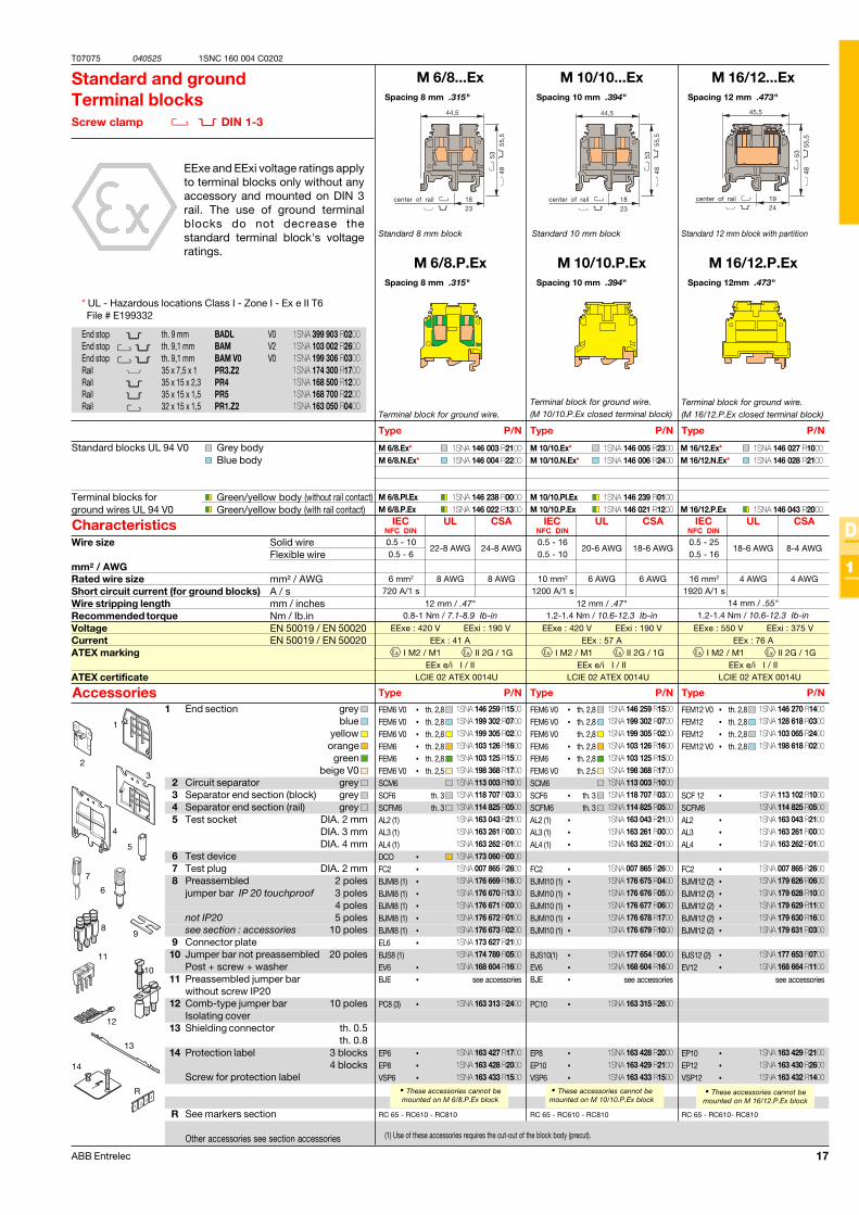
Standard and groundTerminal blocksScrew clamp DIN 1-3
EExe and EExi voltage ratings applyto terminal blocks only without anyaccessory and mounted on DIN 3rail. The use of ground terminalblocks do not decrease thestandard terminal block's voltageratings.
Terminal block for ground wire.
(1) Use of these accessories requires the cut-out of the block body (precut).
• These accessories cannot bemounted on M 6/8.P.Ex block
1 End section grey blue
yellow orange
green beige V0
2 Circuit separator grey 3 Separator end section (block) grey 4 Separator end section (rail) grey 5 Test socket DIA. 2 mm
DIA. 3 mmDIA. 4 mm
6 Test device7 Test plug DIA. 2 mm8 Preassembled 2 poles
jumper bar IP 20 touchproof 3 poles4 poles
not IP20 5 polessee section : accessories 10 poles
9 Connector plate10 Jumper bar not preassembled 20 poles
Post + screw + washer11 Preassembled jumper bar
without screw IP2012 Comb-type jumper bar 10 poles
Isolating cover13 Shielding connector th. 0.5
th. 0.814 Protection label 3 blocks
4 blocksScrew for protection label
R See markers section
Other accessories see section accessories
Type P/N
Standard blocks UL 94 V0 Grey bodyBlue body
Terminal blocks for Green/yellow body (without rail contact)ground wires UL 94 V0 Green/yellow body (with rail contact)
Characteristics
Type P/NAccessories
End stop th. 9 mm BADL V0End stop th. 9,1 mm BAM V2End stop th. 9,1 mm BAM V0 V0Rail 35 x 7,5 x 1 PR3.Z2Rail 35 x 15 x 2,3 PR4Rail 35 x 15 x 1,5 PR5Rail 32 x 15 x 1,5 PR1.Z2
Wire size Solid wireFlexible wire
mm² / AWGRated wire size mm² / AWGShort circuit current (for ground blocks) A / sWire stripping length mm / inchesRecommended torque Nm / Ib.inVoltage EN 50019 / EN 50020Current EN 50019 / EN 50020ATEX marking
ATEX certificate
Spacing 10 mm .394"
Spacing 10 mm .394"
Standard 10 mm block
• These accessories cannot bemounted on M 10/10.P.Ex block
Type P/N
Type P/N
Spacing 12 mm .473"
Spacing 12mm .473"
Standard 12 mm block with partition
Terminal block for ground wire.(M 16/12.P.Ex closed terminal block)
Type P/N
Type P/N
th. 2,8 th. 2,8 th. 2,8 th. 2,8 th. 2,8 th. 2,5
th. 3 th. 3
see accessories
th. 2,8 th. 2,8 th. 2,8 th. 2,8 th. 2,8 th. 2,5
th. 3 th. 3
see accessories
th. 2,8 th. 2,8 th. 2,8 th. 2,8
see accessories
Terminal block for ground wire.(M 10/10.P.Ex closed terminal block)
• These accessories cannot bemounted on M 16/12.P.Ex block
* UL - Hazardous locations Class I - Zone I - Ex e II T6 File # E199332
1SNA 399 903 R02001SNA 103 002 R26001SNA 199 306 R03001SNA 174 300 R17001SNA 168 500 R12001SNA 168 700 R22001SNA 163 050 R0400
1SNA 146 003 R21001SNA 146 004 R2200
1SNA 146 238 R00001SNA 146 022 R1300
1SNA 146 005 R23001SNA 146 006 R2400
1SNA 146 239 R01001SNA 146 021 R1200
1SNA 146 259 R15001SNA 199 302 R07001SNA 199 305 R02001SNA 103 126 R16001SNA 103 125 R15001SNA 198 368 R17001SNA 113 003 R10001SNA 118 707 R03001SNA 114 825 R05001SNA 163 043 R21001SNA 163 261 R00001SNA 163 262 R01001SNA 173 060 R00001SNA 007 865 R26001SNA 176 669 R16001SNA 176 670 R13001SNA 176 671 R00001SNA 176 672 R01001SNA 176 673 R02001SNA 173 627 R21001SNA 174 789 R05001SNA 168 604 R1600
1SNA 163 313 R2400
1SNA 163 427 R17001SNA 163 428 R20001SNA 163 433 R1500
1SNA 146 259 R15001SNA 199 302 R07001SNA 199 305 R02001SNA 103 126 R16001SNA 103 125 R15001SNA 198 368 R17001SNA 113 003 R10001SNA 118 707 R03001SNA 114 825 R05001SNA 163 043 R21001SNA 163 261 R00001SNA 163 262 R0100
1SNA 007 865 R26001SNA 176 675 R04001SNA 176 676 R05001SNA 176 677 R06001SNA 176 678 R17001SNA 176 679 R1000
1SNA 177 654 R00001SNA 168 604 R1600
1SNA 163 315 R2600
1SNA 163 428 R20001SNA 163 429 R21001SNA 163 433 R1500
1SNA 146 270 R14001SNA 128 618 R03001SNA 103 065 R24001SNA 198 618 R0200
1SNA 113 102 R10001SNA 114 825 R05001SNA 163 043 R21001SNA 163 261 R00001SNA 163 262 R0100
1SNA 007 865 R26001SNA 179 626 R06001SNA 179 628 R10001SNA 179 629 R11001SNA 179 630 R16001SNA 179 631 R0300
1SNA 177 653 R07001SNA 168 664 R1100
1SNA 163 429 R21001SNA 163 430 R26001SNA 163 432 R1400
1SNA 146 027 R10001SNA 146 028 R2100
1SNA 146 043 R2000
18 ABB Entrelec
T07076 040525
D
1
1SNC 160 004 C0202
IEC UL CSANFC DIN
M 35/16...Ex
M 35/16.P.Ex
M 35/16.Ex*M 35/16.N.Ex*
M 35/16.P.Ex
RC 65 - RC610 - RC810
6
1
3
2
5
4
7
17 mm / .67"2.8-3 Nm / 24.9-26.7 Ib-in
35 mm2 0 AWG 0 AWG4200 A/1s
1 - 50 10-0 AWG 10-0 AWG1 - 35 10-1 AWG 10-1 AWG
R
FEM16 V0 •FEM16 V0 •FEM16 •FEM16 V0 •
AL4 •FC4 •BJM16 (1) •BJM16 (1) •BJM16 (1) •BJM16 (1) •BJM16 (1) •BJS16 (1) •EV16 •
EP12 •EP16 •VSP16 •
EExe : 750 V EExi : 375 VEEx : 125 A
I M2 / M1 II 2G / 1GEEx e/i I / II
LCIE 02 ATEX 0014U
IEC UL CSANFC DIN
M 70/22...Ex
M 70/22.P.Ex
M 70/22.Ex*M 70/22.N.Ex*
M 70/22.P.Ex
RC 65 - RC610 - RC810
25 mm / .98"6-7 Nm / 53.4-62.3 Ib-in
70 mm2 00 AWG 00 AWG8400 A/1s
16 - 954-00 AWG 4-00 AWG
16 - 70
FEM22 V0
FEM22V0 •SCF22
BJS22(1) •BJS22(1) •BJS22(1) •BJS22(1) •VSJ51 •RDJ51 •EP223 •EP224 •VSP22 •
M 95/26...Ex
M 95/26.P.Ex
RC 65 - RC610- RC810
26 mm / 1.02"8.5-9.5 Nm / 74-83 Ib-in
35 - 1200000 AWG 000 AWG
35 - 95
BJS261 •BJS261 •BJS261 •BJS261 •VSJ51 •RDJ51 •
IEC UL CSANFC DIN
EExe : 660 V EExi : 375 VEEx : 192 A
I M2 / M1 II 2G / 1GEEx e/i I / II
LCIE 02 ATEX 0027U / 0023U
EExe : 750 V EExi : 375 VEEx : 232 A
I M2 / M1 II 2G / 1GEEx e/i I / II
LCIE 02 ATEX 0022U / 0023U
95 mm² 0000 AWG 000 AWG11400 A/1s
M 95/26.ExM 95/26.N.Ex
M 95/26.P.Ex
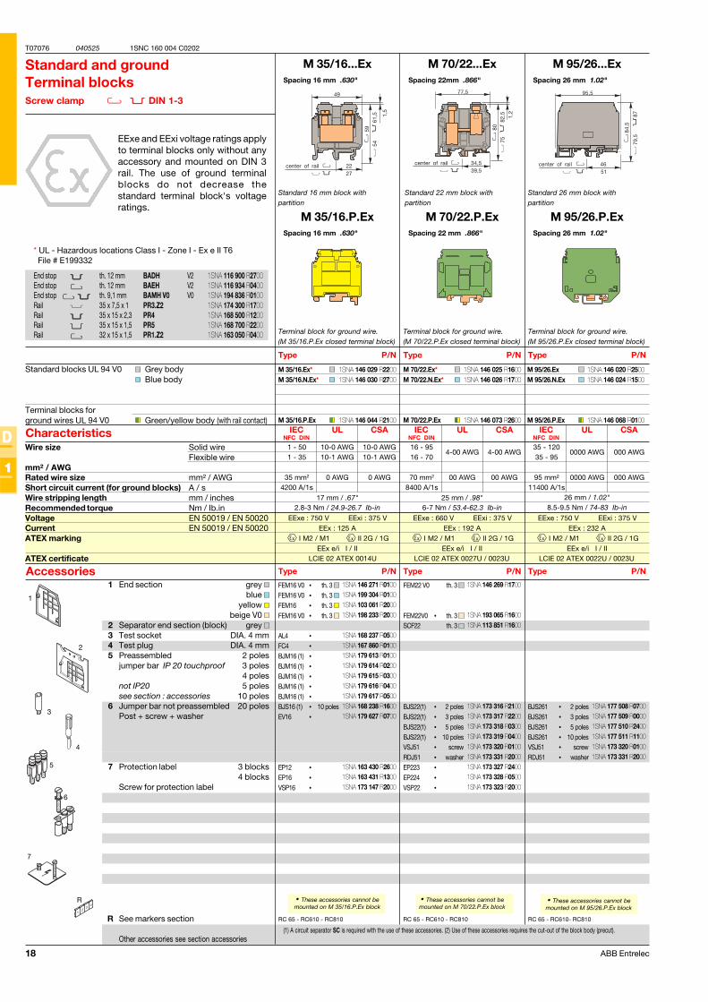
Spacing 16 mm .630"
Spacing 16 mm .630"
Standard 16 mm block withpartition
Standard and groundTerminal blocksScrew clamp DIN 1-3
EExe and EExi voltage ratings applyto terminal blocks only without anyaccessory and mounted on DIN 3rail. The use of ground terminalblocks do not decrease thestandard terminal block's voltageratings.
Terminal block for ground wire.(M 35/16.P.Ex closed terminal block)
(1) A circuit separator SC is required with the use of these accessories. (2) Use of these accessories requires the cut-out of the block body (precut).
• These accessories cannot bemounted on M 35/16.P.Ex block
1 End section grey blue
yellow beige V0
2 Separator end section (block) grey 3 Test socket DIA. 4 mm4 Test plug DIA. 4 mm5 Preassembled 2 poles
jumper bar IP 20 touchproof 3 poles4 poles
not IP20 5 polessee section : accessories 10 poles
6 Jumper bar not preassembled 20 polesPost + screw + washer
7 Protection label 3 blocks4 blocks
Screw for protection label
R See markers section
Other accessories see section accessories
Type P/N
Standard blocks UL 94 V0 Grey bodyBlue body
Terminal blocks forground wires UL 94 V0 Green/yellow body (with rail contact)
Characteristics
Type P/NAccessories
End stop th. 12 mm BADH V2End stop th. 12 mm BAEH V2End stop th. 9,1 mm BAMH V0 V0Rail 35 x 7,5 x 1 PR3.Z2Rail 35 x 15 x 2,3 PR4Rail 35 x 15 x 1,5 PR5Rail 32 x 15 x 1,5 PR1.Z2
Wire size Solid wireFlexible wire
mm² / AWGRated wire size mm² / AWGShort circuit current (for ground blocks) A / sWire stripping length mm / inchesRecommended torque Nm / Ib.inVoltage EN 50019 / EN 50020Current EN 50019 / EN 50020ATEX marking
ATEX certificate
Spacing 22mm .866"
Spacing 22 mm .866"
Standard 22 mm block withpartition
• These accessories cannot bemounted on M 70/22.P.Ex block
Type P/N
Type P/N
Spacing 26 mm 1.02"
Spacing 26 mm 1.02"
Standard 26 mm block withpartition
Terminal block for ground wire.(M 95/26.P.Ex closed terminal block)
Type P/N
Type P/N
th. 3 th. 3 th. 3 th. 3
10 poles
th. 3
th. 3 th. 3
2 poles3 poles5 poles
10 polesscrew
washer
2 poles3 poles5 poles
10 polesscrew
washer
Terminal block for ground wire.(M 70/22.P.Ex closed terminal block)
• These accessories cannot bemounted on M 95/26.P.Ex block
* UL - Hazardous locations Class I - Zone I - Ex e II T6 File # E199332
1SNA 116 900 R27001SNA 116 934 R04001SNA 194 836 R01001SNA 174 300 R17001SNA 168 500 R12001SNA 168 700 R22001SNA 163 050 R0400
1SNA 146 029 R22001SNA 146 030 R2700
1SNA 146 044 R2100
1SNA 146 025 R16001SNA 146 026 R1700
1SNA 146 073 R2600
1SNA 146 271 R01001SNA 199 304 R01001SNA 103 061 R20001SNA 198 233 R2000
1SNA 168 237 R05001SNA 167 860 R01001SNA 179 613 R01001SNA 179 614 R02001SNA 179 615 R03001SNA 179 616 R04001SNA 179 617 R05001SNA 168 238 R16001SNA 179 627 R0700
1SNA 163 430 R26001SNA 163 431 R13001SNA 173 147 R2000
1SNA 146 269 R1700
1SNA 193 065 R16001SNA 113 851 R1600
1SNA 173 316 R21001SNA 173 317 R22001SNA 173 318 R03001SNA 173 319 R04001SNA 173 320 R01001SNA 173 331 R20001SNA 173 327 R24001SNA 173 328 R05001SNA 173 323 R2000
1SNA 177 508 R07001SNA 177 509 R00001SNA 177 510 R24001SNA 177 511 R11001SNA 173 320 R01001SNA 173 331 R2000
1SNA 146 020 R25001SNA 146 024 R1500
1SNA 146 068 R0100
19ABB Entrelec
T07077 040525
D
1
1SNC 160 004 C0202
IEC UL CSANFC DIN
MA 2,5/5.D2... .Ex
MA 2,5/5.D2.1.Ex
MA 2,5/5.D2.ExMA 2,5/5.D2.N.Ex
MA 2,5/5.D2.1.Ex
RC510
9 mm / .35"0.4-0.6 Nm / 3.5-5.3 Ib-in
2.5 mm2 12 AWG 12 AWG
0.2 - 422-12 AWG 20-12 AWG
0.22 - 2.5
FEM6D V0FEM6FEM6D V0SCMA5D (3)
AL2 (1)
DCVFC2BJM5D (1) (2)BJM5D (1) (2)BJM5D (1) (2)BJM5D (1) (2)BJM5D (1) (2)BJMI5D (1) (2)BJMI5D (1) (2)BJMI5D (1) (2)BJMI5D (1) (2)BJMI5D (1) (2)EL6BJS5D (1) (2)EV5DPC5EIPITV5CBM5D
EExe : 380 V EExi : 90 VEEx : 24 A
I M2 / M1 II 2G / 1GEEx e/i I / II
LCIE 02 ATEX 0026U
IEC UL CSANFC DIN
M 4/6.D2.Ex
M 4/6.D2.Ex
RC65 - RC610
4 mm² 12 AWG 12 AWG8.5 mm / .33"
0.5-0.8 Nm / 4.4-7.1 lb.in
0.2 - 422-12 AWG 24-12 AWG
0.22 - 4
FEM6D V0FEM6DFEM6D V0SCM6D (3)SCM6D V0 (3)SCF6DAL2 (1)AL3 (1)DCGFC2BJM6D (1) (2)BJM6D (1) (2)BJM6D (1) (2)BJM6D (1) (2)BJM6D (1) (2)BJMI6D (1) (2)BJMI6D (1) (2)BJMI6D (1) (2)BJMI6D (1) (2)BJMI6D (1) (2)EL6BJS61 (1) (2)EV6DPC61
ITV6CBM5D
3
R
2
12
13
11
10
7
9
6
5
4
1
8
EExe : 380 V EExi : 190 VEEx : 32 A
I M2 / M1 II 2G / 1GEEx e/i I / II
LCIE 02 ATEX 0019U
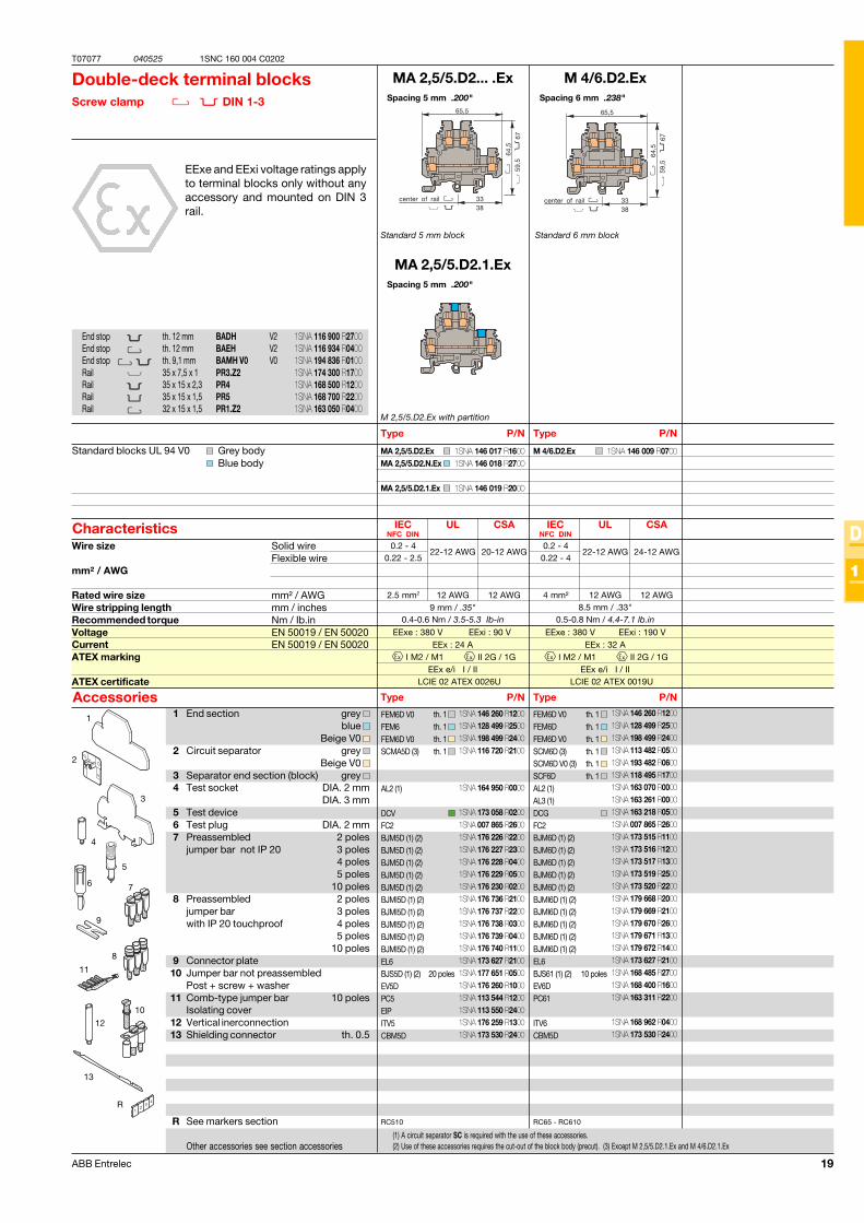
Spacing 5 mm .200"
Spacing 5 mm .200"
Standard 5 mm block
Double-deck terminal blocksScrew clamp DIN 1-3
EExe and EExi voltage ratings applyto terminal blocks only without anyaccessory and mounted on DIN 3rail.
M 2,5/5.D2.Ex with partition
1 End section grey blue
Beige V0 2 Circuit separator grey
Beige V0 3 Separator end section (block) grey 4 Test socket DIA. 2 mm
DIA. 3 mm5 Test device6 Test plug DIA. 2 mm7 Preassembled 2 poles
jumper bar not IP 20 3 poles4 poles5 poles
10 poles8 Preassembled 2 poles
jumper bar 3 poleswith IP 20 touchproof 4 poles
5 poles10 poles
9 Connector plate10 Jumper bar not preassembled
Post + screw + washer11 Comb-type jumper bar 10 poles
Isolating cover12 Vertical inerconnection13 Shielding connector th. 0.5
R See markers section
Other accessories see section accessories
Type P/N
Standard blocks UL 94 V0 Grey bodyBlue body
Characteristics
Type P/NAccessories
Wire size Solid wireFlexible wire
mm² / AWG
Rated wire size mm² / AWGWire stripping length mm / inchesRecommended torque Nm / Ib.inVoltage EN 50019 / EN 50020Current EN 50019 / EN 50020ATEX marking
ATEX certificate
Spacing 6 mm .238"
Standard 6 mm block
Type P/N
Type P/N
th. 1 th. 1 th. 1 th. 1
20 poles
th. 1 th. 1 th. 1 th. 1 th. 1 th. 1
10 poles
(1) A circuit separator SC is required with the use of these accessories.(2) Use of these accessories requires the cut-out of the block body (precut). (3) Except M 2,5/5.D2.1.Ex and M 4/6.D2.1.Ex
End stop th. 12 mm BADH V2End stop th. 12 mm BAEH V2End stop th. 9,1 mm BAMH V0 V0Rail 35 x 7,5 x 1 PR3.Z2Rail 35 x 15 x 2,3 PR4Rail 35 x 15 x 1,5 PR5Rail 32 x 15 x 1,5 PR1.Z2
1SNA 146 017 R16001SNA 146 018 R2700
1SNA 146 019 R2000
1SNA 146 009 R0700
1SNA 146 260 R12001SNA 128 499 R25001SNA 198 499 R24001SNA 116 720 R2100
1SNA 164 950 R0000
1SNA 173 058 R02001SNA 007 865 R26001SNA 176 226 R22001SNA 176 227 R23001SNA 176 228 R04001SNA 176 229 R05001SNA 176 230 R02001SNA 176 736 R21001SNA 176 737 R22001SNA 176 738 R03001SNA 176 739 R04001SNA 176 740 R11001SNA 173 627 R21001SNA 177 651 R05001SNA 176 260 R10001SNA 113 544 R12001SNA 113 550 R24001SNA 176 259 R13001SNA 173 530 R2400
1SNA 146 260 R12001SNA 128 499 R25001SNA 198 499 R24001SNA 113 482 R05001SNA 193 482 R06001SNA 118 495 R17001SNA 163 070 R00001SNA 163 261 R00001SNA 163 218 R05001SNA 007 865 R26001SNA 173 515 R11001SNA 173 516 R12001SNA 173 517 R13001SNA 173 519 R25001SNA 173 520 R22001SNA 179 668 R20001SNA 179 669 R21001SNA 179 670 R26001SNA 179 671 R13001SNA 179 672 R14001SNA 173 627 R21001SNA 168 485 R27001SNA 168 400 R16001SNA 163 311 R2200
1SNA 168 962 R04001SNA 173 530 R2400
1SNA 116 900 R27001SNA 116 934 R04001SNA 194 836 R01001SNA 174 300 R17001SNA 168 500 R12001SNA 168 700 R22001SNA 163 050 R0400
20 ABB Entrelec
T07078 040225
D
1
1SNC 160 004 C0202
IEC UL CSANFC DIN
D 2,5/6.DA...Ex
D 2,5/6.DA.ExD 2,5/6.DA.N.Ex
6 mm / .24"0.4-0.6 Nm / 3.5-5.3 Ib-in
2.5 mm2 12 AWG 14 AWG
0.2 - 2.520-12 AWG 22-14 AWG
0.22 - 2.5
FED3EBJD6BJD6BJD6BJD6BJD6BJD6EL61AD2,5
3
R
2
4
1
EExe : 60 V EExi : 30 VEEx : 22 A
I M2 / M1 II 2G / 1GEEx e/i I / II
LCIE 03 ATEX 0024U
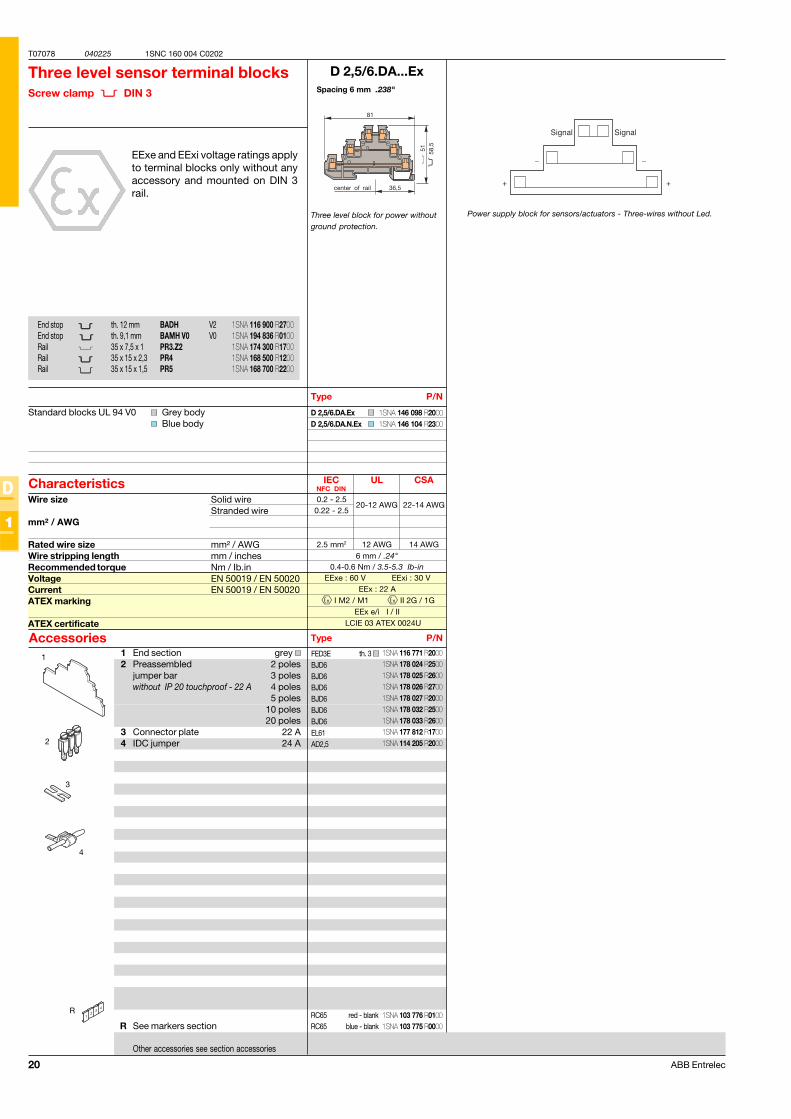
Spacing 6 mm .238"
Three level block for power withoutground protection.
Three level sensor terminal blocksScrew clamp DIN 3
EExe and EExi voltage ratings applyto terminal blocks only without anyaccessory and mounted on DIN 3rail.
1 End section grey 2 Preassembled 2 poles
jumper bar 3 poleswithout IP 20 touchproof - 22 A 4 poles
5 poles10 poles20 poles
3 Connector plate 22 A4 IDC jumper 24 A
R See markers section
Other accessories see section accessories
Type P/N
Standard blocks UL 94 V0 Grey bodyBlue body
Characteristics
Type P/NAccessories
Wire size Solid wireStranded wire
mm² / AWG
Rated wire size mm² / AWGWire stripping length mm / inchesRecommended torque Nm / Ib.inVoltage EN 50019 / EN 50020Current EN 50019 / EN 50020ATEX marking
ATEX certificate
th. 3
End stop th. 12 mm BADH V2End stop th. 9,1 mm BAMH V0 V0Rail 35 x 7,5 x 1 PR3.Z2Rail 35 x 15 x 2,3 PR4Rail 35 x 15 x 1,5 PR5
Power supply block for sensors/actuators - Three-wires without Led.
RC65 red - blankRC65 blue - blank
1SNA 116 771 R20001SNA 178 024 R25001SNA 178 025 R26001SNA 178 026 R27001SNA 178 027 R20001SNA 178 032 R25001SNA 178 033 R26001SNA 177 812 R17001SNA 114 205 R2000
1SNA 116 900 R27001SNA 194 836 R01001SNA 174 300 R17001SNA 168 500 R12001SNA 168 700 R2200
1SNA 103 776 R01001SNA 103 775 R0000
1SNA 146 098 R20001SNA 146 104 R2300
21ABB Entrelec
T07080 040528
D
1
1SNC 160 004 C0202
IEC BS UL/CSANFC DIN TS 50-18
M 4/6.RS.Ex
RC610
FEMR8
AL2
FC2BJS6 (1)BJS6 (1)BJS6 (1)BJS6 (1)BJS6 (1)
BJS6 (1)EV6
BJM6 (1)BJM6 (1)BJM6 (1)BJM6 (1)BJM6 (1)BJMI6 (1)BJMI6 (1)BJMI6 (1)BJMI6 (1)BJMI6 (1)
M 6/8.RS.Ex
M 6/8.RS.Ex
RC810
13 mm / .51"0.8-1 Nm / 7.1-8.9 Ib-in
6 mm2 2.5 mm2 12 AWG
0.5 - 100.5 - 6 20-12 AWG
0.28 - 2.5
FEMR8FEMR8 V0
AL4FC4BJS8 (1)BJS8 (1)BJS8 (1)BJS8 (1)BJS8 (1)BJS8 (1)BJS8 (1)EV6
BJM8 (1)BJM8 (1)BJM8 (1)BJM8 (1)BJM8 (1)BJMI8 (1)BJMI8 (1)BJMI8 (1)BJMI8 (1)BJMI8 (1)BP8.A4
M 10/10.RS.Ex
RC610- RC810
14 mm / .55"1.2-1.4 Nm / 10.6-12.3 Ib-in
0.5 - 160.5 - 10 20-6 AWG
0.28 - 6
FEMR10FEMR10 V0
AL4FC4BJS10 (1)BJS10 (1)BJS10 (1)BJS10 (1)BJS10 (1)BJS10 (1)
PT101
VSJ11
EExe : 550 V EExi : 375 VEEx : 41 A
I M2 / M1 II 2G / 1GEEx e/i I / II
LCIE 02 ATEX 0012U
EExe : 550 V EExi : 375 VEEx : 41 A
I M2 / M1 II 2G / 1GEEx e/i I / II
LCIE 02 ATEX 0012U
10 mm2 6 mm2 6 AWG
M 10/10.RS.Ex
1 FEMR8
FEMR10
23
4
5
7
R
6
BJS10 +PL101 +VSJ11
BJS8 + EV6
M 4/6.RS.Ex
13 mm / .51"0.5-0.8 Nm / 4.4-7.1 Ib-in
4 mm2 1.65 mm2 12 AWG
0.2 - 40.22 - 4 22-12 AWG
0.5 - 1.5 0.28 - 1.65
IEC BS UL/CSANFC DIN TS 50-18
IEC BS UL/CSANFC DIN TS 50-18
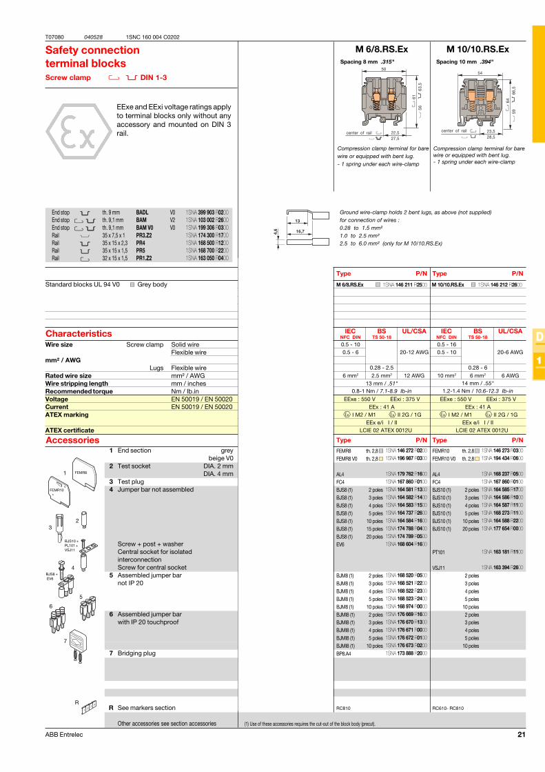
Spacing 6 mm .238"
Compression clamp terminal for barewire or equipped with bent lug.- 1 spring under each wire-clamp
Safety connectionterminal blocksScrew clamp DIN 1-3
EExe and EExi voltage ratings applyto terminal blocks only without anyaccessory and mounted on DIN 3rail.
(1) Use of these accessories requires the cut-out of the block body (precut).
Type P/N
Standard blocks UL 94 V0 Grey body
Characteristics
Type P/NAccessories
End stop th. 9 mm BADL V0End stop th. 9,1 mm BAM V2End stop th. 9,1 mm BAM V0 V0Rail 35 x 7,5 x 1 PR3.Z2Rail 35 x 15 x 2,3 PR4Rail 35 x 15 x 1,5 PR5Rail 32 x 15 x 1,5 PR1.Z2
Wire size Screw clamp Solid wireFlexible wire
mm² / AWGLugs Flexible wire
Rated wire size mm² / AWGWire stripping length mm / inchesRecommended torque Nm / Ib.inVoltage EN 50019 / EN 50020Current EN 50019 / EN 50020ATEX marking
ATEX certificate
Spacing 8 mm .315"
Compression clamp terminal for barewire or equipped with bent lug.- 1 spring under each wire-clamp
Type P/N
Type P/N
Spacing 10 mm .394"
Compression clamp terminal for barewire or equipped with bent lug.- 1 spring under each wire-clamp
Type P/N
Type P/N
th. 2,8
2 poles3 poles4 poles5 poles
10 poles
20 poles
2 poles3 poles4 poles5 poles
10 poles2 poles3 poles4 poles5 poles
10 poles
th. 2,8 th. 2,8
2 poles3 poles4 poles5 poles
10 poles15 poles20 poles
2 poles3 poles4 poles5 poles
10 poles2 poles3 poles4 poles5 poles
10 poles
th. 2,8 th. 2,8
2 poles3 poles4 poles5 poles
10 poles20 poles
2 poles3 poles4 poles5 poles
10 poles2 poles3 poles4 poles5 poles
10 poles
1 End section greybeige V0
2 Test socket DIA. 2 mmDIA. 4 mm
3 Test plug4 Jumper bar not assembled
Screw + post + washerCentral socket for isolatedinterconnectionScrew for central socket
5 Assembled jumper barnot IP 20
6 Assembled jumper barwith IP 20 touchproof
7 Bridging plug
R See markers section
Other accessories see section accessories
Ground wire-clamp holds 2 bent lugs, as above (not supplied)for connection of wires :0.28 to 1.5 mm²1.0 to 2.5 mm²2.5 to 6.0 mm² (only for M 10/10.RS.Ex)
center of rail
In progress
1SNA 399 903 R02001SNA 103 002 R26001SNA 199 306 R03001SNA 174 300 R17001SNA 168 500 R12001SNA 168 700 R22001SNA 163 050 R0400
1SNA 146 211 R2500
1SNA 146 272 R0200
1SNA 163 043 R2100
1SNA 007 865 R26001SNA 164 573 R22001SNA 164 574 R23001SNA 164 575 R24001SNA 164 736 R25001SNA 164 576 R2500
1SNA 174 784 R20001SNA 168 604 R1600
1SNA 168 516 R25001SNA 168 517 R26001SNA 168 518 R07001SNA 168 519 R00001SNA 168 973 R07001SNA 176 663 R00001SNA 176 664 R01001SNA 176 665 R02001SNA 176 666 R03001SNA 176 667 R0400
1SNA 146 272 R02001SNA 196 987 R0300
1SNA 179 762 R16001SNA 167 860 R01001SNA 164 581 R13001SNA 164 582 R14001SNA 164 583 R15001SNA 164 737 R26001SNA 164 584 R16001SNA 174 788 R04001SNA 174 789 R05001SNA 168 604 R1600
1SNA 168 520 R05001SNA 168 521 R22001SNA 168 522 R23001SNA 168 523 R24001SNA 168 974 R00001SNA 176 669 R16001SNA 176 670 R13001SNA 176 671 R00001SNA 176 672 R01001SNA 176 673 R02001SNA 173 888 R2000
1SNA 146 273 R03001SNA 194 434 R0600
1SNA 168 237 R05001SNA 167 860 R01001SNA 164 585 R17001SNA 164 586 R10001SNA 164 587 R11001SNA 168 273 R11001SNA 164 588 R22001SNA 177 654 R0000
1SNA 163 181 R1100
1SNA 163 394 R2600
1SNA 146 212 R2600
22 ABB Entrelec
T07081 040217
D
1
1SNC 160 004 C0202
MTC 6.Ex
31 mm max. / 1.22"0.4-0.6 Nm / 3.5-5.3 lb.in
FEM6 V0CBM5CBM6
RC65 - RC610
MTC 6.Ex
EExe : 550 V EExi : 90 V
I M2 / M1 II 2G / 1GEEx e/i I / II
LCIE 02 ATEX 0025U
1
2
R
Spacing 6 mm .238"
6 mm block for thermocouple wires.
Thermocoupleterminal blocksScrew clamp DIN 1-3
EExe and EExi voltage ratings applyto terminal blocks only without anyaccessory and mounted on DIN 3rail.
Type P/N
Standard blocks UL 94 V0 Grey body
Characteristics
Type P/NAccessories
End stop th. 9 mm BADL V0End stop th. 9,1 mm BAM V2End stop th. 9,1 mm BAM V0 V0Rail 35 x 7,5 x 1 PR3.Z2Rail 35 x 15 x 2,3 PR4Rail 35 x 15 x 1,5 PR5Rail 32 x 15 x 1,5 PR1.Z2
Wire size Solid wireFlexible wire
mm² / AWG With isolated ferrule
Rated wire size mm² / AWGWire stripping length mm / inchesRecommended torque Nm / Ib.inVoltage EN 50019 / EN 50020Current EN 50019 / EN 50020ATEX marking
ATEX certificate
1 End section grey 2 Shield connector
R See markers section
Other accessories see section accessories
th. 2.8 th. 0.5th. 0.8
2 Conductors forthermocouple
(DIA. 0.9 - 1.5 mm)
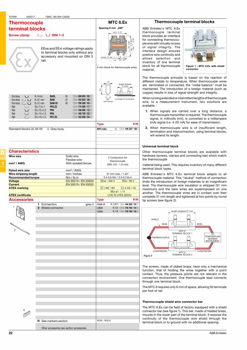
Thermocouple terminal blocks
ABB Entrelec's MTC 6.Exthermocouple terminalblock provides an interfacefor connecting thermocou-ple wire with virtually no lossof signal integrity. Theinterface design ensurespositive wire continuity andallows selection andinventory of one terminalblock for all thermocouplematerial.
Figure 1 : MTC 6.Ex with shieldconnector
The thermocouple principle is based on the reaction ofdifferent metals to temperature. When thermocouple wiresare terminated or connected, the "metal balance" must bemaintained. The introduction of a foreign material (such ascopper) results in loss of signal strength and integrity.
When running extended or intermittent lengths of thermocouplewire, to a measurement instrument, two solutions areavailable :
1. When signals are carried over a long distance, athermocouple transmitter is required. The thermocouplesignal, in millivolts (mV), is converted to a milliampere(mA) signal (i.e. 4-20 mA) for ease of transmission.
2. When thermocouple wire is of insufficient length,termination and interconnection, using terminal blocks,will extend its length.
Universal terminal block
Other thermocouple terminal blocks are available withhardware (screws, clamps and connecting bar) which matchthe thermocouple
material being used. This requires inventory of many differentterminal block types.
ABB Entrelec's MTC 6.Ex terminal block adapts to allthermocouple material. This "neutral" method of connectionlimits the introduction of foreign materials to an insignificantlevel. The thermocouple wire insulation is stripped (31 mmmaximum) and the bare wires are superimposed on oneanother. The thermocouple wires are in contact over theircomplete 31 mm length and tightened at two points by roundtip screws (see figure 2).
The screws, made of plated brass, have only a mechanicalfunction, that of holding the wires together with a pointcontact. Thus, the pressure points are not relevant in theconnection environment. One thermocouple lead connectsthrough one terminal block.
The MTC 6 requires only 6 mm of space, allowing 50 terminalsper foot of rail.
Thermocouple shield wire connector bar
The MTC 6.Ex can be field of factory equipped with a shieldconnector bar (see figure 1). This bar, made of treated brass,mounts in the lower part of the terminal block. It ensures thecontinuity of the thermocouple wire shield through theterminal block or to ground with no additional spacing.
1SNA 399 903 R02001SNA 103 002 R26001SNA 199 306 R03001SNA 174 300 R17001SNA 168 500 R12001SNA 168 700 R22001SNA 163 050 R0400
1SNA 146 259 R15001SNA 178 745 R14001SNA 178 746 R1500
1SNA 146 227 R2500
23ABB Entrelec
T07082 040526
D
1
1SNC 160 004 C0202
D 35/27.FF.Ex D 70/32.FF.Ex
1
2
3
R
D 35/27.FF.Ex
D 35/27.FF.Ex
H10 mm / 6 pans creux 6 mm3 Nm / 26.1 Ib-in / 6 Nm / 52 Ib-in .
35 mm² 35 mm² 1 AWG
(C4) 2.5 - 35 2.5 - 50 1 AWG(C4) 2.5 - 35 2.5 - 35 1 AWG
CPUF35
BJS27BJS27DRF6
IEC IEC UL/CSANFC DIN
H13 mm / 6 pans creux 6 mm6 Nm / 52 Ib-in / 6 Nm / 52 Ib-in .
70 mm² 70 mm² 000 AWG
(C6) 6 - 95 6 - 70 000 AWG(C6) 6 - 70 6 - 70 000 AWG
IEC IEC UL/CSANFC DIN
CPUF70
BJS32BJS32DRF8
D 120/42.FF.Ex
H17 mm / 6 pans creux 6 mm10 Nm / 87 Ib-in / 6 Nm / 52 Ib-in .
120 mm² 120 mm² 300 MCM
(C8) 6 - 150 6 - 120 300 MCM(C8) 6 - 120 300 MCM
IEC IEC UL/CSANFC DIN
CPUF120
BJS42BJS42DRF10
D 70/32.FF.Ex
D 70/32.FF.Ex
D 120/42.FF.Ex
D 120/42.FF.Ex
750 V125 A
I M1 - II 2GEEx e
LCIE 03 ATEX 0034U
750 V192 A
I M1 - II 2GEEx e
LCIE 03 ATEX 0034U
750 V269 A
I M1 - II 2GEEx e
LCIE 03 ATEX 0034U
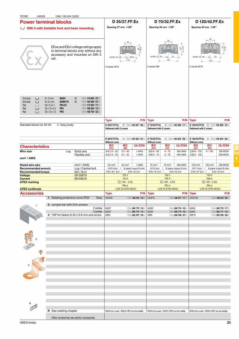
Spacing 27 mm 1.06"
Power terminal blocks DIN 3 with bistable foot and base mounting
EExe and EExi voltage ratings applyto terminal blocks only without anyaccessory and mounted on DIN 3rail.
Type P/N
Characteristics
Type P/NAccessories
Wire size Lug Solid wireFlexible wire
mm² / AWG
Rated wire size mm² / AWGRecommended wrench Lug / Central boltRecommended torque Nm / Ib.inVoltage EN 50019Current EN 50019ATEX marking
ATEX certificate
Spacing 32 mm 1.26"
Type P/N
Type P/N
2 studs M10 2 studs M8
End stop th. 12 mm BADH V2End stop th. 9,1 mm BAMH V0 V0Rail 35 x 7,5 x 1 PR3.Z2Rail 35 x 15 x 2,3 PR4Rail 35 x 15 x 1,5 PR5
1 Rotating protective cover IP20 Grey
2 Jumper bar with CHc screws2 poles3 poles
3 TAP for faston 6.35 x 0.8 mm and screw
R See marking chapter
Other accessories see section accessories
Standard block UL 94 V0 Grey body
Spacing 42 mm 1.65"
Type P/N
Type P/N
2 studs M10
Delivered with 2 covers
Without cover
RC810 (on cover) - RC810, RPC (on the middle) RC810 (on cover) - RC810, RPC (on the middle) RC810 (on cover) - RC810, RPC (on the middle)
Delivered with 2 covers
Without cover
Delivered with 2 covers
Without cover
1SNA 116 900 R27001SNA 194 836 R01001SNA 174 300 R17001SNA 168 500 R12001SNA 168 700 R2200
1SNA 190 016 R1600
1SNA 205 772 R13001SNA 205 773 R14001SNA 205 767 R1600
1SNA 190 017 R1700
1SNA 205 774 R15001SNA 205 775 R16001SNA 205 768 R2700
1SNA 190 018 R2000
1SNA 205 776 R17001SNA 205 777 R10001SNA 205 769 R2000
1SNA 146 307 R0600
1SNA 146 302 R0100
1SNA 146 308 R1700
1SNA 146 303 R0200
1SNA 146 309 R1000
1SNA 146 304 R0300
24 ABB Entrelec
T07083 040526
D
1
1SNC 160 004 C0202
D 185/55.FF.Ex D 300/55.FF.Ex
1
2
3
R
H19 mm / 6 pans creux 6 mm14 Nm / 121 Ib-in / 6 Nm / 52 Ib-in .
185 mm² 185 mm² 500 MCM
(C11) 25 - 240 6 - 185 500 MCM(C11) 6 - 185 500 MCM
CPUF185
BJS51BJS51DRF12
IEC IEC UL/CSANFC DIN
H24 mm / 6 pans creux 6 mm25 Nm / 217 Ib-in / 6 Nm / 52 Ib-in .
300 mm² 300 mm² 1000 MCM
25 - 300 6 - 300 1000 MCM6 - 300 1000 MCM
IEC IEC UL/CSANFC DIN
CPUF185
BJS51BJS51DRF16
D 185/55.FF.Ex
D 185/55.FF.Ex
D 300/55.FF.Ex
D 300/55.FF.Ex
750 V353 A
I M1 - II 2GEEx e
LCIE 03 ATEX 0034U
750 V520 A
I M1 - II 2GEEx e
LCIE 03 ATEX 0034U
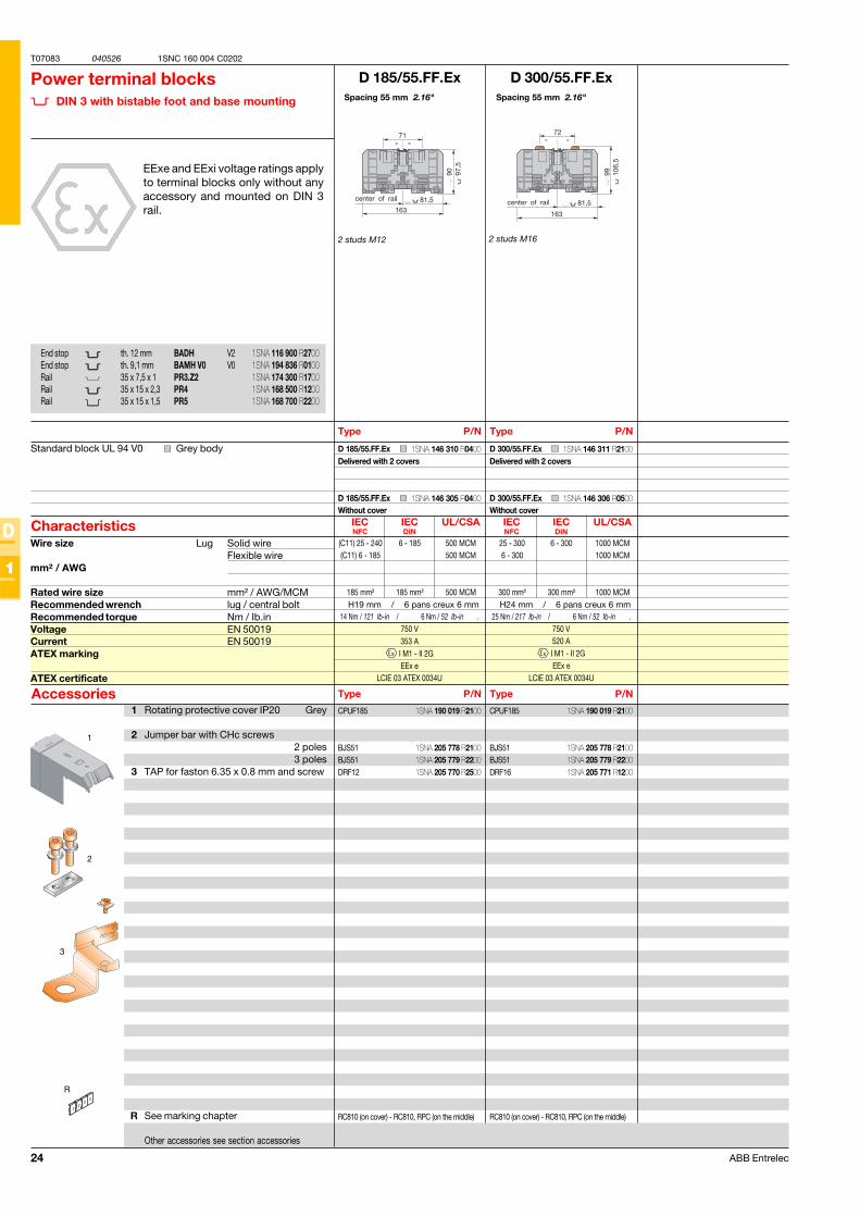
Spacing 55 mm 2.16"
Power terminal blocks DIN 3 with bistable foot and base mounting
EExe and EExi voltage ratings applyto terminal blocks only without anyaccessory and mounted on DIN 3rail.
Type P/N
Characteristics
Type P/NAccessories
Wire size Lug Solid wireFlexible wire
mm² / AWG
Rated wire size mm² / AWG/MCMRecommended wrench lug / central boltRecommended torque Nm / Ib.inVoltage EN 50019Current EN 50019ATEX marking
ATEX certificate
Spacing 55 mm 2.16"
Type P/N
Type P/N
2 studs M12 2 studs M16
End stop th. 12 mm BADH V2End stop th. 9,1 mm BAMH V0 V0Rail 35 x 7,5 x 1 PR3.Z2Rail 35 x 15 x 2,3 PR4Rail 35 x 15 x 1,5 PR5
1 Rotating protective cover IP20 Grey
2 Jumper bar with CHc screws2 poles3 poles
3 TAP for faston 6.35 x 0.8 mm and screw
R See marking chapter
Other accessories see section accessories
Standard block UL 94 V0 Grey body
RC810 (on cover) - RC810, RPC (on the middle) RC810 (on cover) - RC810, RPC (on the middle)
Delivered with 2 covers
Without cover
Delivered with 2 covers
Without cover
1SNA 116 900 R27001SNA 194 836 R01001SNA 174 300 R17001SNA 168 500 R12001SNA 168 700 R2200
1SNA 190 019 R2100
1SNA 205 778 R21001SNA 205 779 R22001SNA 205 770 R2500
1SNA 190 019 R2100
1SNA 205 778 R21001SNA 205 779 R22001SNA 205 771 R1200
1SNA 146 310 R0400
1SNA 146 305 R0400
1SNA 146 311 R2100
1SNA 146 306 R0500
25ABB Entrelec
T07089 040526
D
1
1SNC 160 004 C0202
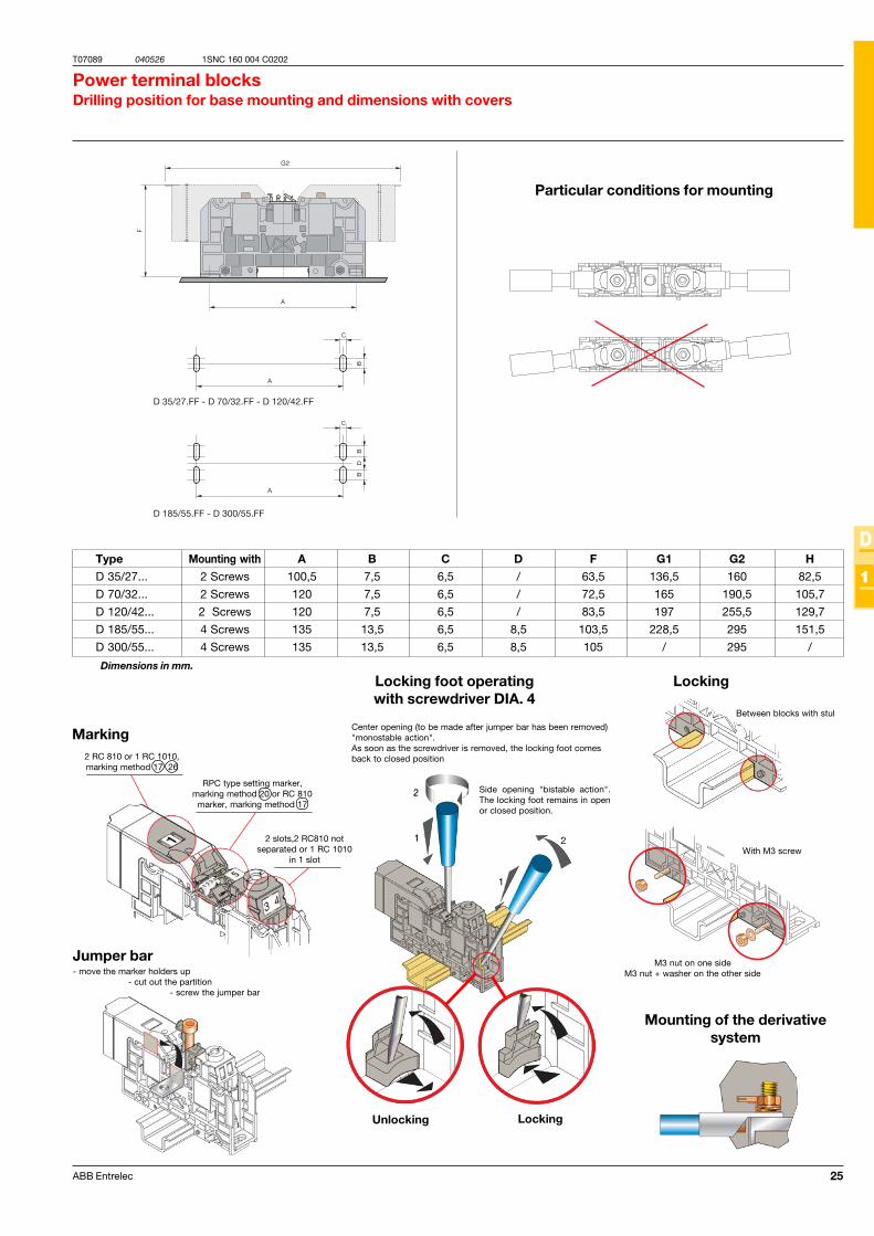
Power terminal blocksDrilling position for base mounting and dimensions with covers
Locking foot operatingwith screwdriver DIA. 4
Marking
Jumper bar- move the marker holders up
- cut out the partition- screw the jumper bar
Side opening "bistable action".The locking foot remains in openor closed position.
Center opening (to be made after jumper bar has been removed)"monostable action".As soon as the screwdriver is removed, the locking foot comesback to closed position
Locking
LockingUnlocking
Mounting of the derivativesystem
Dimensions in mm.
Type Mounting with A B C D F G1 G2 H
D 35/27... 2 Screws 100,5 7,5 6,5 / 63,5 136,5 160 82,5
D 70/32... 2 Screws 120 7,5 6,5 / 72,5 165 190,5 105,7
D 120/42... 2 Screws 120 7,5 6,5 / 83,5 197 255,5 129,7
D 185/55... 4 Screws 135 13,5 6,5 8,5 103,5 228,5 295 151,5
D 300/55... 4 Screws 135 13,5 6,5 8,5 105 / 295 /
RPC type setting marker,marking method 20 or RC 810
marker, marking method 17
2 RC 810 or 1 RC 1010,marking method 17 26
2 slots,2 RC810 notseparated or 1 RC 1010
in 1 slot
Between blocks with stul
With M3 screw
M3 nut on one sideM3 nut + washer on the other side
Particular conditions for mounting
26 ABB Entrelec
T07084 040525
D
1
1SNC 160 004 C0202
IEC UL CSANFC DIN
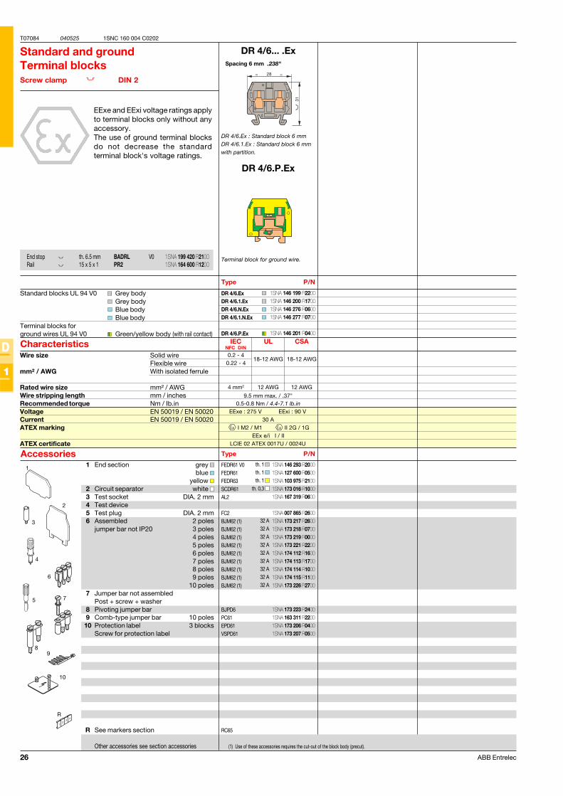
DR 4/6... .Ex
FEDR61 V0FEDR61FEDR63SCDR61AL2
FC2BJM62 (1)BJM62 (1)BJM62 (1)BJM62 (1)BJM62 (1)BJM62 (1)BJM62 (1)BJM62 (1)BJM62 (1)
BJPD6PC61EPD61VSPD61
RC65
DR 4/6.ExDR 4/6.1.ExDR 4/6.N.ExDR 4/6.1.N.Ex
DR 4/6.P.Ex
EExe : 275 V EExi : 90 V30 A
I M2 / M1 II 2G / 1GEEx e/i I / II
LCIE 02 ATEX 0017U / 0024U
DR 4/6.P.Ex
5
4
1
2
6
3
9
10
R
7
9.5 mm max. / .37"0.5-0.8 Nm / 4.4-7.1 lb.in
0.2 - 418-12 AWG 18-12 AWG
0.22 - 4
4 mm2 12 AWG 12 AWG
8
Spacing 6 mm .238"
Standard and groundTerminal blocksScrew clamp DIN 2
EExe and EExi voltage ratings applyto terminal blocks only without anyaccessory.The use of ground terminal blocksdo not decrease the standardterminal block's voltage ratings.
Type P/N
Standard blocks UL 94 V0 Grey bodyGrey bodyBlue bodyBlue body
Terminal blocks forground wires UL 94 V0 Green/yellow body (with rail contact)
Characteristics
Type P/NAccessories
End stop th. 6.5 mm BADRL V0Rail 15 x 5 x 1 PR2
Wire size Solid wireFlexible wire
mm² / AWG With isolated ferrule
Rated wire size mm² / AWGWire stripping length mm / inchesRecommended torque Nm / Ib.inVoltage EN 50019 / EN 50020Current EN 50019 / EN 50020ATEX marking
ATEX certificate
1 End section grey blue
yellow 2 Circuit separator white 3 Test socket DIA. 2 mm4 Test device5 Test plug DIA. 2 mm6 Assembled 2 poles
jumper bar not IP20 3 poles4 poles5 poles6 poles7 poles8 poles9 poles
10 poles7 Jumper bar not assembled
Post + screw + washer8 Pivoting jumper bar9 Comb-type jumper bar 10 poles10 Protection label 3 blocks
Screw for protection label
R See markers section
Other accessories see section accessories
th. 1 th. 1 th. 1
th. 0,3
32 A32 A32 A32 A32 A32 A32 A32 A32 A
Terminal block for ground wire.
(1) Use of these accessories requires the cut-out of the block body (precut).
DR 4/6.Ex : Standard block 6 mmDR 4/6.1.Ex : Standard block 6 mmwith partition.
1SNA 146 293 R20001SNA 127 600 R05001SNA 103 975 R21001SNA 173 016 R10001SNA 167 319 R0600
1SNA 007 865 R26001SNA 173 217 R26001SNA 173 218 R07001SNA 173 219 R00001SNA 173 221 R22001SNA 174 112 R16001SNA 174 113 R17001SNA 174 114 R10001SNA 174 115 R11001SNA 173 226 R2700
1SNA 173 223 R24001SNA 163 311 R22001SNA 173 206 R04001SNA 173 207 R0500
1SNA 199 420 R21001SNA 164 600 R1200
1SNA 146 199 R22001SNA 146 200 R17001SNA 146 276 R06001SNA 146 277 R0700
1SNA 146 201 R0400
27ABB Entrelec
T07085 040217
D
1
1SNC 160 004 C0202
IEC UL/CSANFC DIN
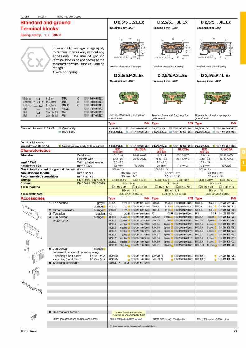
D 2,5/5... .2L.Ex
D 2,5/5.P.2L.Ex
D 2,5/5.2L.ExD 2,5/5.N.2L.Ex
D 2,5/5.P.2L.Ex
9.5 mm / .37"3.5 mm / .14"
2.5 mm2 12 AWG300 A / 1 s
0.12 - 4 26-12 AWG0.12 - 2.5 26-12 AWG0.5 - 2.5
EExe : 550 V EExi : 60 VEEx : 24 A
I M2 / M1 II 2G / 1GEEx e/i I / II
LCIE 02 ATEX 0031U
D 2,5/5... .3L.Ex
D 2,5/5.P.3L.Ex
D 2,5/5.3L.ExD 2,5/5.N.3L.Ex
D 2,5/5.P.3L.Ex
9.5 mm / .37"3.5 mm / .14"
2.5 mm2 12 AWG300 A / 1 s
0.12 - 4 26-12 AWG0.12 - 2.5 26-12 AWG0.5 - 2.5
D 2,5/5... .4L.Ex
9.5 mm / .37"3.5 mm / .14"
0.12 - 4 26-12 AWG0.12 - 2.5 26-12 AWG0.5 - 2.5
EExe : 550 V EExi : 60 VEEx : 24 A
I M2 / M1 II 2G / 1GEEx e/i I / II
LCIE 02 ATEX 0010U
EExe : 550 V EExi : 60 VEEx : 24 A
I M2 / M1 II 2G / 1GEEx e/i I / II
LCIE 02 ATEX 0010U
2.5 mm2 12 AWG300 A / 1 s
D 2,5/5.4L.ExD 2,5/5.N.4L.Ex
D 2,5/5.P.4L.Ex
FED5.2LFED5.2LSCD5.2LFC2BJDL5.2BJDL5.3BJDL5.4BJDL5.5BJDL5.6BJDL5.7BJDL5.8BJDL5.9BJDL5.10
BJDPL56 (1)BJDPL58 (1)CBD5.2L •
FED5.3LFED5.3LSCD5.3LFC2BJDL5.2BJDL5.3BJDL5.4BJDL5.5BJDL5.6BJDL5.7BJDL5.8BJDL5.9BJDL5.10
BJDPL56 (1)BJDPL58 (1)
FED5.4LFED5.4LSCD5.4LFC2BJDL5.2BJDL5.3BJDL5.4BJDL5.5BJDL5.6BJDL5.7BJDL5.8BJDL5.9BJDL5.10
BJDPL56 (1)BJDPL58 (1)
R
1
4
6
3
2
5
D 2,5/5.P.4L.Ex
IEC UL/CSANFC DIN
IEC UL/CSANFC DIN
Spacing 5 mm .200"
Spacing 5 mm .200"
Terminal block with 2 springs
Standard and groundTerminal blocksSpring clamp DIN 2
EExe and EExi voltage ratings applyto terminal blocks only without anyaccessory. The use of groundterminal blocks do not decrease thestandard terminal blocks' voltageratings.1 wire per spring.
Terminal block with 2 springs forground wire.
(1) Insert an end section between the 2 connected blocks
• This accessory cannot bemounted on M 2.5/5.P.L2.Ex block
1 End section grey orange
2 Circuit separator orange 3 Test plug black 4 Jumper bar orange
IP 20 - 24 A
5 Jumper bar orange between 2 blocks, different spacing- spacing 5 and 6 mm IP 20 - 24 A- spacing 5 and 8 mm IP 20 - 24 A
6 Shielding connector
R See markers section
Other accessories see section accessories
Type P/N
Standard blocks UL 94 V0 Grey bodyBlue body
Terminal blocks forground wires UL 94 V0 Green/yellow body (with rail contact)
Characteristics
Type P/NAccessories
End stop th. 9 mm BADL V0End stop th. 9,1 mm BAM V2End stop th. 9,1 mm BAM V0 V0Rail 35 x 7,5 x 1 PR3.Z2Rail 35 x 15 x 2,3 PR4Rail 35 x 15 x 1,5 PR5
Wire size Solid wireFlexible wire
mm² / AWG With isolated ferruleRated wire size mm² / AWGShort circuit current (for ground blocks) A / sWire stripping length mm / inchesRecommended screwdriver mm / inchesVoltage EN 50019 / EN 50020Current EN 50019 / EN 50020ATEX marking
ATEX certificate
Spacing 5 mm .200"
Spacing 5 mm .200"
Terminal block with 3 spring
Type P/N
Type P/N
Spacing 5 mm .200"
Terminal block with 4 spring
Type P/N
Type P/N
Terminal block with 3 springs forground wire
29
45,5
38
58
center of rail
th. 2,5 th. 2,5 th. 2,5
Ø 2 2 poles 3 poles 4 poles 5 poles 6 poles 7 poles 8 poles 9 poles 10 poles
th. 0,5
Spacing 5 mm .200"
Terminal block with 4 springs forground wire
th. 2,5 th. 2,5 th. 2,5
Ø 2 2 poles 3 poles 4 poles 5 poles 6 poles 7 poles 8 poles 9 poles 10 poles
th. 2,5 th. 2,5 th. 2,5
Ø 2 2 poles 3 poles 4 poles 5 poles 6 poles 7 poles 8 poles 9 poles 10 poles
RC510, RPC (on top) - RC55 (on side) RC510, RPC (on top) - RC55 (on side) RC510, RPC (on top) - RC55 (on side)
40
45,5
38
80
center of rail
1SNA 399 903 R02001SNA 103 002 R26001SNA 199 306 R03001SNA 174 300 R17001SNA 168 500 R12001SNA 168 700 R2200
1SNA 146 053 R22001SNA 146 052 R2100
1SNA 146 054 R2300
1SNA 146 055 R24001SNA 146 056 R2500
1SNA 146 057 R2600
1SNA 291 061 R24001SNA 291 062 R25001SNA 291 352 R04001SNA 007 865 R26001SNA 291 102 R23001SNA 291 103 R24001SNA 291 104 R25001SNA 291 105 R26001SNA 291 106 R27001SNA 291 107 R20001SNA 291 108 R01001SNA 291 109 R02001SNA 291 110 R2600
1SNA 291 150 R06001SNA 291 160 R00001SNA 291 077 R2400
1SNA 291 051 R22001SNA 291 052 R23001SNA 291 362 R06001SNA 007 865 R26001SNA 291 102 R23001SNA 291 103 R24001SNA 291 104 R25001SNA 291 105 R26001SNA 291 106 R27001SNA 291 107 R20001SNA 291 108 R01001SNA 291 109 R02001SNA 291 110 R2600
1SNA 291 150 R06001SNA 291 160 R0000
1SNA 291 041 R20001SNA 291 042 R21001SNA 291 372 R00001SNA 007 865 R26001SNA 291 102 R23001SNA 291 103 R24001SNA 291 104 R25001SNA 291 105 R26001SNA 291 106 R27001SNA 291 107 R20001SNA 291 108 R01001SNA 291 109 R02001SNA 291 110 R2600
1SNA 291 150 R06001SNA 291 160 R0000
1SNA 146 049 R06001SNA 146 050 R0300
1SNA 146 051 R2000
28 ABB Entrelec
T07086 040217
D
1
1SNC 160 004 C0202
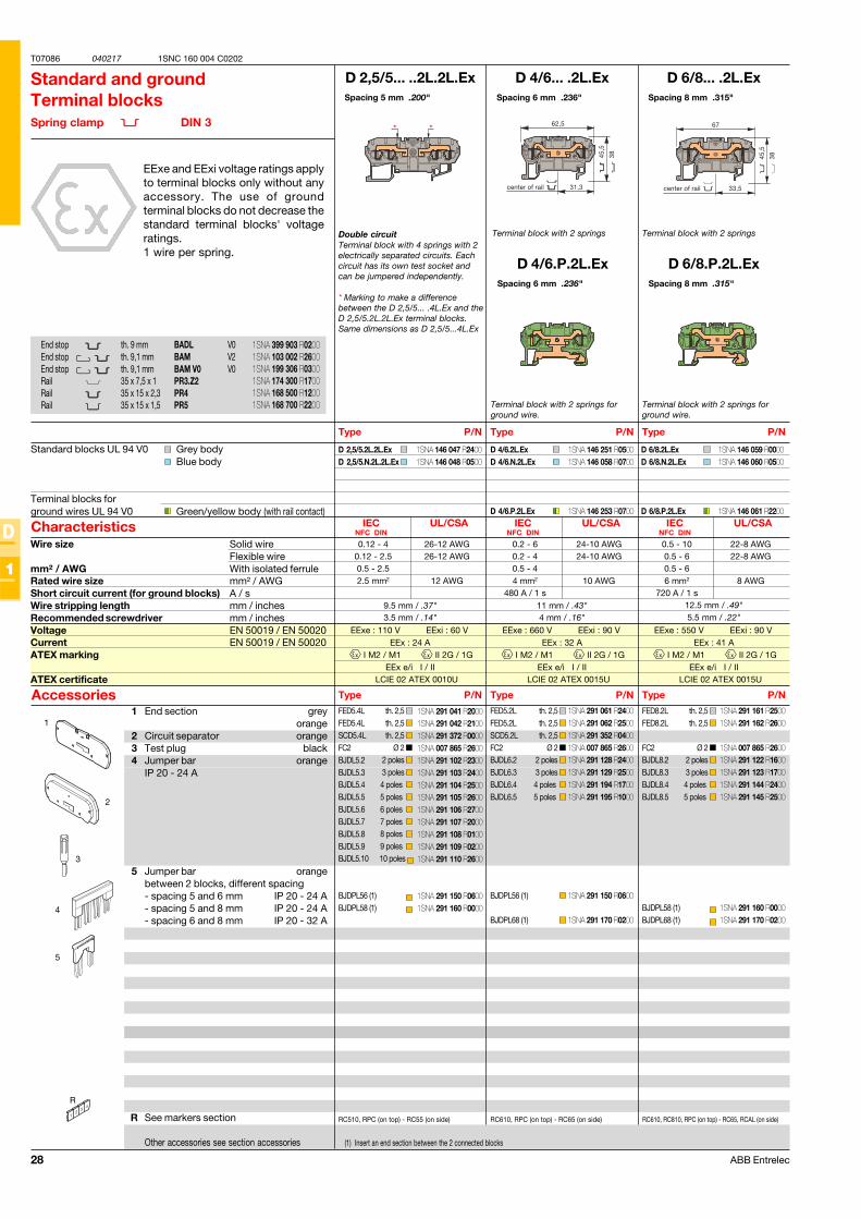
D 2,5/5... ..2L.2L.Ex
D 2,5/5.2L.2L.ExD 2,5/5.N.2L.2L.Ex
9.5 mm / .37"3.5 mm / .14"
EExe : 110 V EExi : 60 VEEx : 24 A
I M2 / M1 II 2G / 1GEEx e/i I / II
LCIE 02 ATEX 0010U
D 4/6... .2L.Ex
D 6/8.P.2L.Ex
D 4/6.2L.ExD 4/6.N.2L.Ex
D 4/6.P.2L.Ex
11 mm / .43"4 mm / .16"
D 6/8... .2L.Ex
12.5 mm / .49"5.5 mm / .22"
EExe : 660 V EExi : 90 VEEx : 32 A
I M2 / M1 II 2G / 1GEEx e/i I / II
LCIE 02 ATEX 0015U
EExe : 550 V EExi : 90 VEEx : 41 A
I M2 / M1 II 2G / 1GEEx e/i I / II
LCIE 02 ATEX 0015U
D 6/8.2L.ExD 6/8.N.2L.Ex
D 6/8.P.2L.Ex
FED5.4LFED5.4LSCD5.4LFC2BJDL5.2BJDL5.3BJDL5.4BJDL5.5BJDL5.6BJDL5.7BJDL5.8BJDL5.9BJDL5.10
BJDPL56 (1)BJDPL58 (1)
R
1
2
5
4
3
FED5.2LFED5.2LSCD5.2LFC2BJDL6.2BJDL6.3BJDL6.4BJDL6.5
BJDPL56 (1)
BJDPL68 (1)
FED8.2LFED8.2L
FC2BJDL8.2BJDL8.3BJDL8.4BJDL8.5
BJDPL58 (1)BJDPL68 (1)
IEC UL/CSANFC DIN
2.5 mm2 12 AWG
0.12 - 4 26-12 AWG0.12 - 2.5 26-12 AWG0.5 - 2.5
IEC UL/CSANFC DIN
4 mm2 10 AWG480 A / 1 s
0.2 - 6 24-10 AWG0.2 - 4 24-10 AWG0.5 - 4
IEC UL/CSANFC DIN
6 mm2 8 AWG720 A / 1 s
0.5 - 10 22-8 AWG0.5 - 6 22-8 AWG0.5 - 6
D 4/6.P.2L.Ex
Spacing 5 mm .200"
Double circuitTerminal block with 4 springs with 2electrically separated circuits. Eachcircuit has its own test socket andcan be jumpered independently.
* Marking to make a differencebetween the D 2,5/5... .4L.Ex and theD 2,5/5.2L.2L.Ex terminal blocks.Same dimensions as D 2,5/5...4L.Ex
Standard and groundTerminal blocksSpring clamp DIN 3
EExe and EExi voltage ratings applyto terminal blocks only without anyaccessory. The use of groundterminal blocks do not decrease thestandard terminal blocks' voltageratings.1 wire per spring.
(1) Insert an end section between the 2 connected blocks
1 End section greyorange
2 Circuit separator orange3 Test plug black4 Jumper bar orange
IP 20 - 24 A
5 Jumper bar orangebetween 2 blocks, different spacing- spacing 5 and 6 mm IP 20 - 24 A- spacing 5 and 8 mm IP 20 - 24 A- spacing 6 and 8 mm IP 20 - 32 A
R See markers section
Other accessories see section accessories
Type P/N
Standard blocks UL 94 V0 Grey bodyBlue body
Terminal blocks forground wires UL 94 V0 Green/yellow body (with rail contact)
Characteristics
Type P/NAccessories
Wire size Solid wireFlexible wire
mm² / AWG With isolated ferruleRated wire size mm² / AWGShort circuit current (for ground blocks) A / sWire stripping length mm / inchesRecommended screwdriver mm / inchesVoltage EN 50019 / EN 50020Current EN 50019 / EN 50020ATEX marking
ATEX certificate
Spacing 6 mm .236"
Spacing 8 mm .315"
Terminal block with 2 springs
Type P/N
Type P/N
Spacing 8 mm .315"
Terminal block with 2 springs
Type P/N
Type P/N
Terminal block with 2 springs forground wire.
th. 2,5 th. 2,5 th. 2,5
Ø 2 2 poles 3 poles 4 poles 5 poles 6 poles 7 poles 8 poles 9 poles 10 poles
th. 2,5 th. 2,5 th. 2,5
Ø 2 2 poles 3 poles 4 poles 5 poles
th. 2,5 th. 2,5
Ø 2 2 poles 3 poles 4 poles 5 poles
RC510, RPC (on top) - RC55 (on side) RC610, RPC (on top) - RC65 (on side)
End stop th. 9 mm BADL V0End stop th. 9,1 mm BAM V2End stop th. 9,1 mm BAM V0 V0Rail 35 x 7,5 x 1 PR3.Z2Rail 35 x 15 x 2,3 PR4Rail 35 x 15 x 1,5 PR5
RC610, RC810, RPC (on top) - RC65, RCAL (on side)
Spacing 6 mm .236"
Terminal block with 2 springs forground wire.
1SNA 146 047 R24001SNA 146 048 R0500
1SNA 146 059 R00001SNA 146 060 R0500
1SNA 146 061 R2200
1SNA 291 041 R20001SNA 291 042 R21001SNA 291 372 R00001SNA 007 865 R26001SNA 291 102 R23001SNA 291 103 R24001SNA 291 104 R25001SNA 291 105 R26001SNA 291 106 R27001SNA 291 107 R20001SNA 291 108 R01001SNA 291 109 R02001SNA 291 110 R2600
1SNA 291 150 R06001SNA 291 160 R0000
1SNA 291 061 R24001SNA 291 062 R25001SNA 291 352 R04001SNA 007 865 R26001SNA 291 128 R24001SNA 291 129 R25001SNA 291 194 R17001SNA 291 195 R1000
1SNA 291 150 R0600
1SNA 291 170 R0200
1SNA 291 161 R25001SNA 291 162 R2600
1SNA 007 865 R26001SNA 291 122 R16001SNA 291 123 R17001SNA 291 144 R24001SNA 291 145 R2500
1SNA 291 160 R00001SNA 291 170 R0200
1SNA 399 903 R02001SNA 103 002 R26001SNA 199 306 R03001SNA 174 300 R17001SNA 168 500 R12001SNA 168 700 R2200
1SNA 146 251 R05001SNA 146 058 R0700
1SNA 146 253 R0700
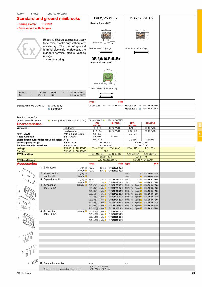
29ABB Entrelec
T07090 040225
D
1
1SNC 160 004 C0202
DR 2,5/5.2L.Ex
9.5 mm / .37"3.5 mm / .14"
FED1.LFED1.L
FED2.LFED2.LBJDL5.2 (1)BJDL5.3 (1)BJDL5.4 (1)BJDL5.5 (1)BJDL5.6 (1)BJDL5.7 (1)BJDL5.8 (1)BJDL5.9 (1)BJDL5.10 (1)BJDL10.2 (2)BJDL10.3 (2)BJDL10.4 (2)BJDL10.5 (2)
DR 2,5/5.2L.Ex
DR 2,5/10.P.4L.Ex
EExe : 275 V EExi : 60 V24 A
I M2 / M1 II 2G / 1GEEx e/i I / II
LCIE 02 ATEX 0031U
R
1
2
5
4
IEC UL/CSANFC DIN
2.5 mm2 12 AWG300 A / 1 s
0.12 - 4 26-12 AWG0.12 - 2.5 26-12 AWG0.5 - 2.5
3
DB 2,5/5.2L.Ex
9.5 mm / .37"3.5 mm / .14"
FEDB.LFEDB.LFED2.LFED2.LBJDL5.2 (1)BJDL5.3 (1)BJDL5.4 (1)BJDL5.5 (1)BJDL5.6 (1)BJDL5.7 (1)BJDL5.8 (1)BJDL5.9 (1)BJDL5.10 (1)
DB 2,5/5.2L.ExDB 2,5/5.N.2L.Ex
IEC UL/CSANFC DIN
2.5 mm2 12 AWG
0.12 - 4 26-12 AWG0.12 - 2.5 26-12 AWG0.5 - 2.5
DR 2,5/10.P.4L.Ex
EExe : 275 V EExi : 60 V24 A
I M2 / M1 II 2G / 1GEEx e/i I / II
LCIE 02 ATEX 0031U
Spacing 5 mm .200"
Miniblock with 2 springs
Standard and ground miniblocks- Spring clamp DIN 2
- Base mount with flanges
EExe and EExi voltage ratings applyto terminal blocks only without anyaccessory. The use of groundterminal blocks do not decrease thestandard terminal blocks' voltageratings.1 wire per spring.
Type P/N
Standard blocks UL 94 V0 Grey bodyBlue body
Terminal blocks forground wires UL 94 V0 Green/yellow body (with rail contact)
Characteristics
Type P/NAccessories
Wire size Solid wireFlexible wire
mm² / AWG With isolated ferruleRated wire size mm² / AWGShort-circuit current (for ground blocks) A / sWire stripping length mm / inchesRecommended screwdriver mm / inchesVoltage EN 50019 / EN 50020Current EN 50019 / EN 50020ATEX marking
ATEX certificate
1 End section grey orange
2 Kit end section grey (right + left) orange
3 Separator section grey orange
4 Jumper bar orange IP 20 - 24 A
5 Jumper bar orange IP 20 - 24 A
R See markers section
Other accessories see section accessories
th. 1.5 th. 1.5
th. 4 th. 4
2 poles 3 poles 4 poles 5 poles 6 poles 7 poles 8 poles 9 poles
10 poles 2 poles 3 poles 4 poles 5 poles
RC55
(1) For D.....2,5/5.2L.Ex only.(2) For DR 2,5/10.P.4L.Ex only.
End stop th. 6.5 mm BADRL V0Rail 15 x 5 x 1 PR2
30
33,5
16,5center of rail
Miniblock with 2 springs
Ground miniblock with 4 springs
th. 4 th. 4
2 poles 3 poles 4 poles 5 poles 6 poles 7 poles 8 poles 9 poles
10 poles
RC55
Type P/N
Spacing 10 mm .396"
1SNA 291 301 R02001SNA 291 302 R0300
1SNA 291 311 R23001SNA 291 312 R24001SNA 291 102 R23001SNA 291 103 R24001SNA 291 104 R25001SNA 291 105 R26001SNA 291 106 R27001SNA 291 107 R20001SNA 291 108 R01001SNA 291 109 R02001SNA 291 110 R26001SNA 291 322 R26001SNA 291 323 R27001SNA 291 324 R20001SNA 291 325 R2100
1SNA 199 420 R21001SNA 164 600 R1200
1SNA 290 281 R01001SNA 290 282 R02001SNA 291 311 R23001SNA 291 312 R24001SNA 291 102 R23001SNA 291 103 R24001SNA 291 104 R25001SNA 291 105 R26001SNA 291 106 R27001SNA 291 107 R20001SNA 291 108 R01001SNA 291 109 R02001SNA 291 110 R2600
1SNA 146 246 R00001SNA 146 247 R0100
1SNA 146 207 R0200
1SNA 146 263 R0100
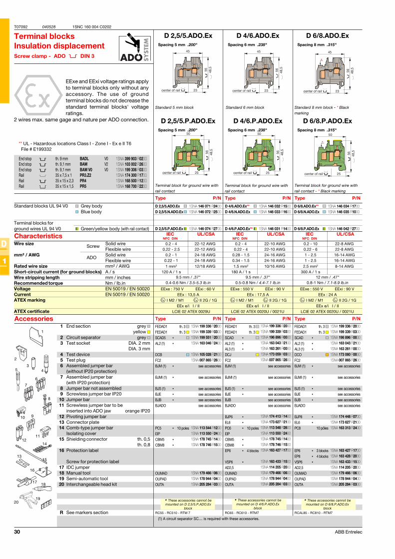
30 ABB Entrelec
T07092 040528
D
1
1SNC 160 004 C0202
D 2,5/5.ADO.Ex
D 2,5/5.P.ADO.Ex
D 2,5/5.ADO.ExD 2,5/5.N.ADO.Ex
D 2,5/5.P.ADO.Ex
RC55 - RC510 - RTM 7
FEDAD1FEDAD1SCAD5 •AL2 (1) •
DCBFC2BJM (1) •
BJMI (1) •
BJS (1) •BJE •BJB •BJADO
PC5 •EIPCBM5 •CBM8 •
OUMADOUPADOUTA
EExe : 750 V EExi : 60 VEEx : 13,5 A
I M2 / M1 II 2G / 1GEEx e/i I / II
LCIE 02 ATEX 0029U
D 4/6.ADO.Ex
D 4/6.P.ADO.Ex
D 4/6.ADO.Ex**D 4/6.N.ADO.Ex
D 4/6.P.ADO.Ex**
RC65 - RC610 - RTM7
D 6/8.ADO.Ex
D 6/8.P.ADO.Ex
RCAL85 - RC810 - RTM7
FEDAD1FEDAD1SCAD •AL2 (1) •AL3 (1) •DCOFC2BJM (1) •
BJMI (1) •
BJS (1) •BJE •BJB •BJADO
BJP8 •EL6 •PC8
EP6 •EP8 •VSP6 •AD2,5OUMADOUPADOUTA
EExe : 550 V EExi : 90 VEEx : 17,5 A
I M2 / M1 II 2G / 1GEEx e/i I / II
LCIE 02 ATEX 0020U / 0021U
EExe : 550 V EExi : 90 VEEx : 24 A
I M2 / M1 II 2G / 1GEEx e/i I / II
LCIE 02 ATEX 0020U / 0021U
D 6/8.ADO.Ex**D 6/8.N.ADO.Ex
D 6/8.P.ADO.Ex
1
2
11
14
345
8
20
15
16
6
10
19
17 18
13
12
7
9
FEDAD1FEDAD1SCAD •AL2 (1) •AL3 (1) •DCJFC2BJM (1)
BJMI (1)
BJS (1) •BJE •BJBBJADO
BJP6 •EL6 •PC6 •EIPCBM5 •CBM8 •EP6 •
VSP6 •AD2,5OUMADOUPADOUTA
9.5 mm / .37"0.4-0.6 Nm / 3.5-5.3 lb.in
IEC UL/CSANFC DIN
1 mm2 12/18 AWG120 A / 1 s
0.2 - 4 22-12 AWG0.22 - 2.5 22-12 AWG
0.2 - 1 24-18 AWG0.22 - 1 24-18 AWG
9.5 mm / .37"0.5-0.8 Nm / 4.4-7.1 lb.in
IEC UL/CSANFC DIN
1.5 mm2 10/16 AWG180 A / 1 s
0.2 - 4 22-10 AWG0.22 - 4 22-10 AWG
0.28 - 1.5 24-16 AWG0.34 - 1.5 24-16 AWG
12 mm / .47"0.8-1 Nm / 7.1-8.9 lb.in
IEC UL/CSANFC DIN
2.5 mm2 8-14 AWG300 A / 1 s
0.2 - 10 22-8 AWG0.22 - 6 22-8 AWG1 - 2.5 16-14 AWG1 - 2.5 16-14 AWG
Spacing 5 mm .200"
Spacing 5 mm .200"
Standard 5 mm block
Terminal blocksInsulation displacementScrew clamp - ADO DIN 3
EExe and EExi voltage ratings applyto terminal blocks only without anyaccessory. The use of groundterminal blocks do not decrease thestandard terminal blocks' voltageratings.
2 wires max. same gage and nature per ADO connection.
Terminal block for ground wire withrail contact
(1) A circuit separator SC.... is required with these accessories.
• These accessories cannot bemounted on D 2,5/5.P.ADO.Ex
block
1 End section grey yellow
2 Circuit separator grey 3 Test socket DIA. 2 mm
DIA. 3 mm4 Test device5 Test plug6 Assembled jumper bar
(without IP20 protection)7 Assembled jumper bar
(with IP20 protection)8 Jumper bar not assembled9 Screwless jumper bar IP2010 Jumper bar11 Screwless jumper bar to be
inserted into ADO jaw orange IP2012 Pivoting jumper bar13 Connector plate14 Comb-type jumper bar
Isolating cover15 Shielding connector th. 0,5
th. 0,816 Protection label
Screw for protection label17 IDC jumper18 Manual tool19 Semi-automatic tool20 Interchangeable head kit
R See markers section
Type P/N
Standard blocks UL 94 V0 Grey bodyBlue body
Terminal blocks forground wires UL 94 V0 Green/yellow body (with rail contact)
Characteristics
Type P/NAccessories
End stop th. 9 mm BADL V0End stop th. 9,1 mm BAM V2End stop th. 9,1 mm BAM V0 V0Rail 35 x 7,5 x 1 PR3.Z2Rail 35 x 15 x 2,3 PR4Rail 35 x 15 x 1,5 PR5
Wire size Solid wireFlexible wire
mm² / AWG Solid wireFlexible wire
Rated wire size mm² / AWGShort-circuit current (for ground blocks) A / sWire stripping length mm / inchesRecommended torque Nm / Ib.inVoltage EN 50019 / EN 50020Current EN 50019 / EN 50020ATEX marking
ATEX certificate
Spacing 6 mm .238"
Spacing 6 mm .238"
Standard 6 mm block
• These accessories cannot bemounted on D 4/6.P.ADO.Ex
block
Type P/N
Type P/N
Spacing 8 mm .315"
Spacing 8 mm .315"
Standard 8 mm block - * Blackmarking
Type P/N
Type P/N
th. 3 th. 3
see accessories
see accessories
see accessoriessee accessoriessee accessoriessee accessories
10 pôles
3 blocks4 blocks
• These accessories cannot bemounted on D 6/8.P.ADO.Ex
block
*
50
25center of rail
48,5
56
Terminal block for ground wire withrail contact
Terminal block for ground wire withrail contact - * Black marking
th. 3 th. 3
see accessories
see accessories
see accessoriessee accessoriessee accessoriessee accessories
10 poles
th. 3 th. 3
see accessories
see accessories
see accessoriessee accessoriessee accessoriessee accessories
10 poles
4 blocks
Screw
ADO
** UL - Hazardous locations Class I - Zone I - Ex e II T6 File # E199332
1SNA 399 903 R02001SNA 103 002 R26001SNA 199 306 R03001SNA 174 300 R17001SNA 168 500 R12001SNA 168 700 R2200
1SNA 146 071 R24001SNA 146 072 R2500
1SNA 146 074 R2700
1SNA 146 032 R15001SNA 146 033 R1600
1SNA 146 031 R1400
1SNA 199 336 R20001SNA 199 339 R03001SNA 199 551 R20001SNA 163 046 R2400
1SNA 105 028 R21001SNA 007 865 R2600
1SNA 113 544 R12001SNA 113 550 R24001SNA 178 745 R14001SNA 178 746 R1500
1SNA 179 466 R06001SNA 178 944 R04001SNA 205 284 R0300
1SNA 199 336 R20001SNA 199 339 R03001SNA 196 896 R00001SNA 163 043 R21001SNA 163 261 R00001SNA 173 060 R00001SNA 007 865 R2600
1SNA 174 448 R07001SNA 173 627 R21001SNA 163 313 R2400
1SNA 163 427 R17001SNA 163 428 R20001SNA 163 433 R15001SNA 114 205 R20001SNA 179 466 R06001SNA 178 944 R04001SNA 205 284 R0300
1SNA 146 034 R17001SNA 146 035 R1000
1SNA 146 042 R2700
1SNA 199 336 R20001SNA 199 339 R03001SNA 196 896 R00001SNA 163 043 R21001SNA 163 261 R00001SNA 173 059 R03001SNA 007 865 R2600
1SNA 174 413 R14001SNA 173 627 R21001SNA 113 548 R26001SNA 113 550 R24001SNA 178 745 R14001SNA 178 746 R15001SNA 163 427 R1700
1SNA 163 433 R15001SNA 114 205 R20001SNA 179 466 R06001SNA 178 944 R04001SNA 205 284 R0300
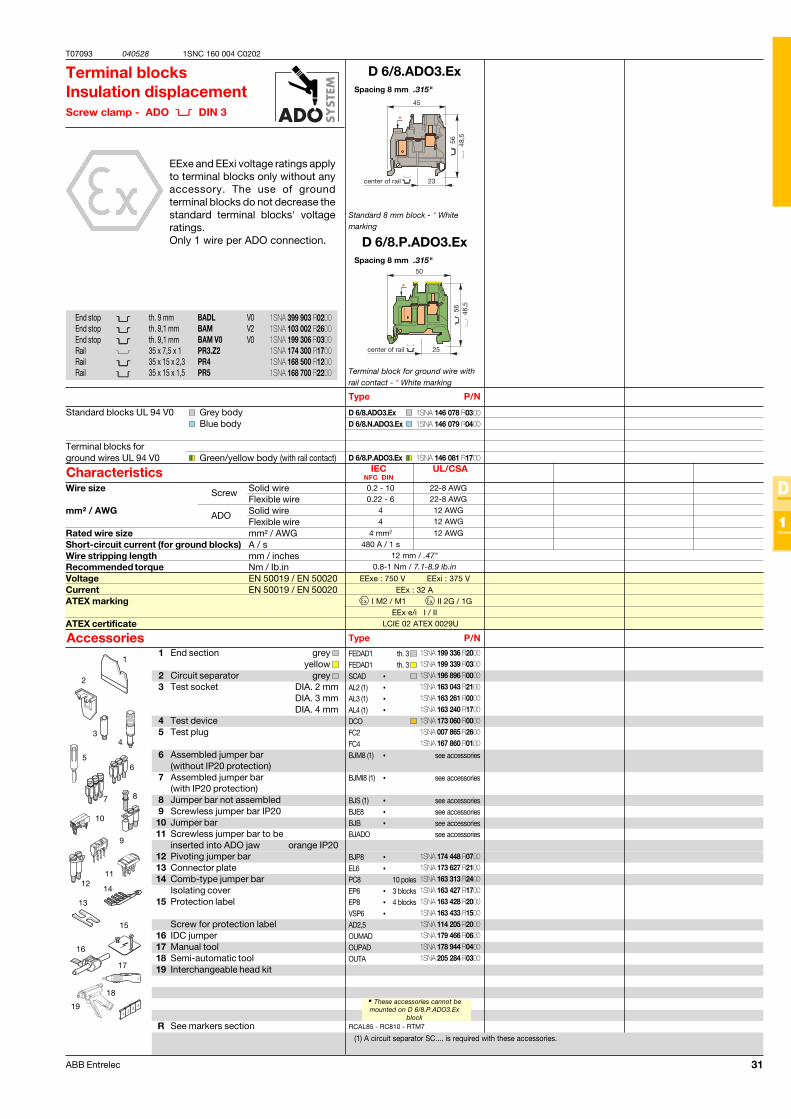
31ABB Entrelec
T07093 040528
D
1
1SNC 160 004 C0202
D 6/8.ADO3.Ex
D 6/8.P.ADO3.Ex
D 6/8.ADO3.ExD 6/8.N.ADO3.Ex
D 6/8.P.ADO3.Ex
EExe : 750 V EExi : 375 VEEx : 32 A
I M2 / M1 II 2G / 1GEEx e/i I / II
LCIE 02 ATEX 0029U
RCAL85 - RC810 - RTM7
FEDAD1FEDAD1SCAD •AL2 (1) •AL3 (1) •AL4 (1) •DCOFC2FC4BJM8 (1) •
BJMI8 (1) •
BJS (1) •BJE8 •BJB •BJADO
BJP8 •EL6 •PC8EP6 •EP8 •VSP6 •AD2,5OUMADOUPADOUTA
1
2
3
12
15
4
56
9
16
17
7
11
18
19
14
13
8
10
12 mm / .47"0.8-1 Nm / 7.1-8.9 lb.in
IEC UL/CSANFC DIN
4 mm2 12 AWG480 A / 1 s
0.2 - 10 22-8 AWG0.22 - 6 22-8 AWG
4 12 AWG4 12 AWG
Spacing 8 mm .315"
Spacing 8 mm .315"
Standard 8 mm block - * Whitemarking
Terminal blocksInsulation displacementScrew clamp - ADO DIN 3
EExe and EExi voltage ratings applyto terminal blocks only without anyaccessory. The use of groundterminal blocks do not decrease thestandard terminal blocks' voltageratings.Only 1 wire per ADO connection.
Terminal block for ground wire withrail contact - * White marking
(1) A circuit separator SC.... is required with these accessories.
1 End section grey yellow
2 Circuit separator grey 3 Test socket DIA. 2 mm
DIA. 3 mmDIA. 4 mm
4 Test device5 Test plug
6 Assembled jumper bar(without IP20 protection)
7 Assembled jumper bar(with IP20 protection)
8 Jumper bar not assembled9 Screwless jumper bar IP2010 Jumper bar11 Screwless jumper bar to be
inserted into ADO jaw orange IP2012 Pivoting jumper bar13 Connector plate14 Comb-type jumper bar
Isolating cover15 Protection label
Screw for protection label16 IDC jumper17 Manual tool18 Semi-automatic tool19 Interchangeable head kit
R See markers section
Type P/N
Standard blocks UL 94 V0 Grey bodyBlue body
Terminal blocks forground wires UL 94 V0 Green/yellow body (with rail contact)
Characteristics
Type P/NAccessories
End stop th. 9 mm BADL V0End stop th. 9,1 mm BAM V2End stop th. 9,1 mm BAM V0 V0Rail 35 x 7,5 x 1 PR3.Z2Rail 35 x 15 x 2,3 PR4Rail 35 x 15 x 1,5 PR5
Wire size Solid wireFlexible wire
mm² / AWG Solid wireFlexible wire
Rated wire size mm² / AWGShort-circuit current (for ground blocks) A / sWire stripping length mm / inchesRecommended torque Nm / Ib.inVoltage EN 50019 / EN 50020Current EN 50019 / EN 50020ATEX marking
ATEX certificate
th. 3 th. 3
see accessories
see accessories
see accessoriessee accessoriessee accessoriessee accessories
10 poles3 blocks4 blocks
• These accessories cannot bemounted on D 6/8.P.ADO3.Ex
block
Screw
ADO
1SNA 399 903 R02001SNA 103 002 R26001SNA 199 306 R03001SNA 174 300 R17001SNA 168 500 R12001SNA 168 700 R2200
1SNA 146 078 R03001SNA 146 079 R0400
1SNA 146 081 R1700
1SNA 199 336 R20001SNA 199 339 R03001SNA 196 896 R00001SNA 163 043 R21001SNA 163 261 R00001SNA 163 240 R17001SNA 173 060 R00001SNA 007 865 R26001SNA 167 860 R0100
1SNA 174 448 R07001SNA 173 627 R21001SNA 163 313 R24001SNA 163 427 R17001SNA 163 428 R20001SNA 163 433 R15001SNA 114 205 R20001SNA 179 466 R06001SNA 178 944 R04001SNA 205 284 R0300
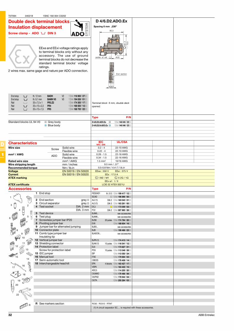
32 ABB Entrelec
T07094 040218
D
1
1SNC 160 004 C0202
D 4/6.D2.ADO.Ex
D 4/6.D2.ADO.ExD 4/6.D2.N.ADO.Ex
RC65 - RC610 - RTM7
EExe : 550 V EExi : 375 VEEx : 17.5 A
I M2 / M1 II 2G / 1GEEx e/i I / II
LCIE 02 ATEX 0021U
9.5 mm / .37"0.5-0.8 Nm / 4.4-7.1 lb.in
IEC UL/CSANFC DIN
1.5 mm2 10/16 AWG
0.2 - 4 22-10 AWG0.22 - 4 22-10 AWG
0.28 - 1.5 22-16 AWG0.34 - 1.5 22-16 AWG
R
1
3
4
6
8
13
14
9
10
5
2
12
15
1617
FED2AD1SCADAL2 (1)AL3 (1)DCJFC2BJM6...BJMI6...BJS6EV6BJE6...BJBBJADO6...
BJP6 (1)BJA6 (1)EL6PC6EIPITVECBD2SEP6VSP6AD2,5OUMADOUPADOUTA
11
7
18
19
20
21
22
Spacing 6 mm .238"
Double deck terminal blocksInsulation displacementScrew clamp - ADO DIN 3
EExe and EExi voltage ratings applyto terminal blocks only without anyaccessory. The use of groundterminal blocks do not decrease thestandard terminal blocks' voltageratings.
2 wires max. same gage and nature per ADO connection.
Terminal block 6 mm, double deckopened.
(1) A circuit separator SC.... is required with these accessories.
Type P/N
Standard blocks UL 94 V0 Grey bodyBlue body
Characteristics
Type P/NAccessories
Wire size Solid wireFlexible wire
mm² / AWG Solid wireFlexible wire
Rated wire size mm² / AWGWire stripping length mm / inchesRecommended torque Nm / Ib.inVoltage EN 50019 / EN 50020Current EN 50019 / EN 50020ATEX marking
ATEX certificate
Screw
ADO
End stop th. 12 mm BADH V2End stop th. 9,1 mm BAMH V0 V0Rail 35 x 7,5 x 1 PR3.Z2Rail 35 x 15 x 2,3 PR4Rail 35 x 15 x 1,5 PR5
1 End stop
2 End section grey 3 Circuit separator grey 4 Test socket DIA. 2 mm
DIA. 3 mm5 Test device6 Test plug7 Screwless jumper bar IP208 Pivoting jumper bar9 Jumper bar for alternated jumping10 Connector plate11 Comb type jumper bar
Insulating tip12 Vertical jumper bar13 Shielding connector14 Protection label
Screw for protection label15 IDC jumper16 Manual tool17 Semi-automatic tool18 Interchangeable head kit
R See markers section
th. 5
DIA 2DIA 3
DIA 2
see accessoriessee accessories
20 poles
see accessories
see accessories
10 poles
10 poles
4 blocks
1SNA 146 045 R22001SNA 146 046 R2300
1SNA 116 900 R27001SNA 194 836 R01001SNA 174 300 R17001SNA 168 500 R12001SNA 168 700 R2200
1SNA 199 417 R12001SNA 196 896 R00001SNA 163 043 R21001SNA 163 261 R00001SNA 173 059 R03001SNA 007 865 R2600
1SNA 174 784 R20001SNA 168 604 R1600
1SNA 199 466 R2300
1SNA 174 413 R14001SNA 116 541 R12001SNA 173 627 R21001SNA 113 548 R26001SNA 113 550 R24001SNA 179 694 R03001SNA 178 408 R14001SNA 163 427 R17001SNA 163 433 R15001SNA 114 205 R20001SNA 179 466 R06001SNA 178 944 R04001SNA 205 284 R0300
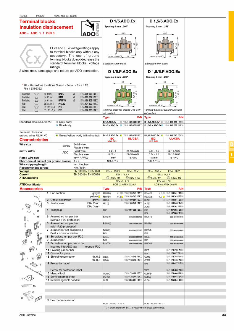
33ABB Entrelec
T07095 040525
D
1
1SNC 160 004 C0202
D 1/5.ADO.Ex
D 1/5.P.ADO.Ex
D 1/5.ADO.ExD 1/5.N.ADO.Ex
D 1/5.P.ADO.Ex
RC55 - RC510 - RTM 7
FEMAD3FEMAD3SCAD5AL2 (1)
FC2
BJM5 (1)
BJMI5 (1)
BJS5 (1)EV5BJE5...BJBBJADO5...
CBM5CBM8
OUMADOUPADOUTA
EExe : 750 V EExi : 60 VEEx : 13,5 A
I M2 / M1 II 2G / 1GEEx e/i I / II
LCIE 02 ATEX 0029U
D 1,5/6.ADO.Ex
D 1,5/6.P.ADO.Ex
D 1,5/6.ADO.Ex*D 1,5/6.N.ADO.Ex
D 1,5/6.P.ADO.Ex*
RC65 - RC610 - RTM7
EExe : 550 V EExi : 90 VEEx : 17,5 A
I M2 / M1 II 2G / 1GEEx e/i I / II
LCIE 02 ATEX 0021U
1
2
3
12
15
4
5
6
9
16
17
7
11
14
13
8
10
FEMAD3FEMAD3SCADAL2 (1)AL3 (1)FC2FC4BJM6 (1)
BJMI6 (1)
BJS6 (1)EV6BJE6...BJBBJADO6...
BJP6EL6CBM5CBM8EP6
VSP6OUMADOUPADOUTA
IEC UL/CSANFC DIN
1 mm2 18 AWG120 A / 1 s
0.2 - 1 24-18 AWG0.22 - 1 24-18 AWG
IEC UL/CSANFC DIN
1.5 mm2 16 AWG180 A / 1 s
0.34 - 1.5 22-16 AWG0.34 - 1.5 22-16 AWG
Spacing 5 mm .200"
Spacing 5 mm .200"
Standard 5 mm block
Terminal blocksInsulation displacementADO - ADO DIN 3
EExe and EExi voltage ratings applyto terminal blocks only without anyaccessory. The use of groundterminal blocks do not decrease thestandard terminal blocks' voltageratings.
2 wires max. same gage and nature per ADO connection.
Terminal block for ground wire withrail contact
(1) A circuit separator SC.... is required with these accessories.
1 End section grey yellow
2 Circuit separator grey 3 Test socket DIA. 2 mm
DIA. 3 mm4 Test plug
5 Assembled jumper bar(without IP20 protection)
6 Assembled jumper bar(with IP20 protection)
7 Jumper bar not assembledPost + screw + washer
8 Screwless jumper bar IP209 Jumper bar10 Screwless jumper bar to be
inserted into ADO jaw orange IP2011 Pivoting jumper bar12 Connector plate13 Shielding connector th. 0,5
th. 0,814 Protection label
Screw for protection label15 Manual tool16 Semi-automatic tool17 Interchangeable head kit
R See markers section
Type P/N
Standard blocks UL 94 V0 Grey bodyBlue body
Terminal blocks forground wires UL 94 V0 Green/yellow body (with rail contact)
Characteristics
Type P/NAccessories
End stop th. 9 mm BADL V0End stop th. 9,1 mm BAM V2End stop th. 9,1 mm BAM V0 V0Rail 35 x 7,5 x 1 PR3.Z2Rail 35 x 15 x 2,3 PR4Rail 35 x 15 x 1,5 PR5
Wire size Solid wireFlexible wire
mm² / AWG Solid wireFlexible wire
Rated wire size mm² / AWGShort-circuit current (for ground blocks) A / sWire stripping length mm / inchesRecommended torque Nm / Ib.inVoltage EN 50019 / EN 50020Current EN 50019 / EN 50020ATEX marking
ATEX certificate
Spacing 6 mm .238"
Spacing 6 mm .238"
Standard 6 mm block
Type P/N
Type P/N
Terminal block for ground wire withrail contact
th. 3 th. 3
see accessories
see accessories
see accessories
see accessoriessee accessoriessee accessories
th. 3 th. 3
see accessories
see accessories
see accessories
see accessoriessee accessoriessee accessories
Screw
ADO
* UL - Hazardous locations Class I - Zone I - Ex e II T6 File # E199332
1SNA 399 903 R02001SNA 103 002 R26001SNA 199 306 R03001SNA 174 300 R17001SNA 168 500 R12001SNA 168 700 R2200
1SNA 146 069 R02001SNA 146 070 R0700
1SNA 146 075 R2000
1SNA 199 341 R05001SNA 199 343 R07001SNA 199 551 R20001SNA 163 046 R2400
1SNA 007 865 R2600
1SNA 178 745 R14001SNA 178 746 R1500
1SNA 179 466 R06001SNA 178 944 R04001SNA 205 284 R0300
1SNA 199 341 R05001SNA 199 343 R07001SNA 199 551 R20001SNA 163 046 R24001SNA 163 261 R00001SNA 007 865 R26001SNA 167 860 R0100
1SNA 174 413 R14001SNA 173 627 R21001SNA 178 745 R14001SNA 178 746 R15001SNA 163 427 R1700
1SNA 163 433 R15001SNA 179 466 R06001SNA 178 944 R04001SNA 205 284 R0300
1SNA 146 036 R11001SNA 146 037 R1200
1SNA 146 040 R0100
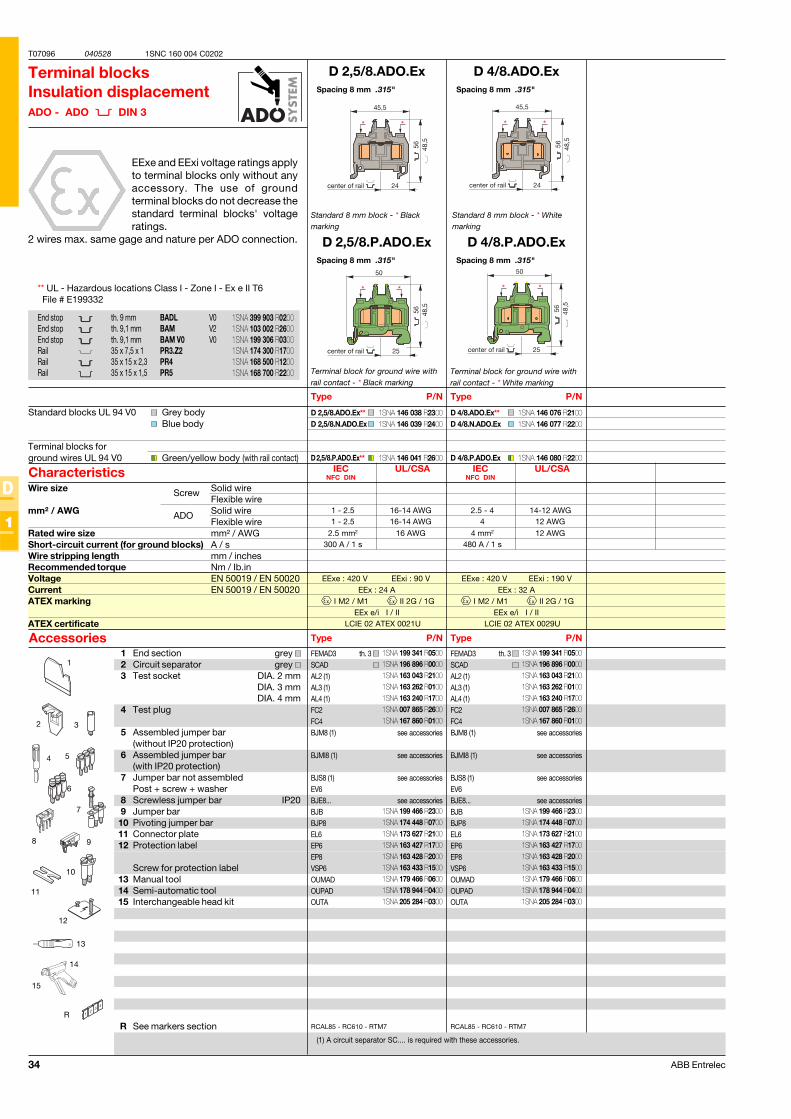
34 ABB Entrelec
T07096 040528
D
1
1SNC 160 004 C0202
D 2,5/8.ADO.Ex
D 2,5/8.P.ADO.Ex
D 2,5/8.ADO.Ex**D 2,5/8.N.ADO.Ex
D 2,5/8.P.ADO.Ex**
RCAL85 - RC610 - RTM7
FEMAD3SCADAL2 (1)AL3 (1)AL4 (1)FC2FC4BJM8 (1)
BJMI8 (1)
BJS8 (1)EV6BJE8...BJBBJP8EL6EP6EP8VSP6OUMADOUPADOUTA
EExe : 420 V EExi : 90 VEEx : 24 A
I M2 / M1 II 2G / 1GEEx e/i I / II
LCIE 02 ATEX 0021U
D 4/8.ADO.Ex
D 4/8.P.ADO.Ex
D 4/8.ADO.Ex**D 4/8.N.ADO.Ex
D 4/8.P.ADO.Ex
EExe : 420 V EExi : 190 VEEx : 32 A
I M2 / M1 II 2G / 1GEEx e/i I / II
LCIE 02 ATEX 0029U
1
2 3
14
4 5
6
9
15
7
11
13
12
8
10
IEC UL/CSANFC DIN
2.5 mm2 16 AWG300 A / 1 s
1 - 2.5 16-14 AWG1 - 2.5 16-14 AWG
IEC UL/CSANFC DIN
4 mm2 12 AWG480 A / 1 s
2.5 - 4 14-12 AWG4 12 AWG
R
FEMAD3SCADAL2 (1)AL3 (1)AL4 (1)FC2FC4BJM8 (1)
BJMI8 (1)
BJS8 (1)EV6BJE8...BJBBJP8EL6EP6EP8VSP6OUMADOUPADOUTA
RCAL85 - RC610 - RTM7
Spacing 8 mm .315"
Spacing 8 mm .315"
Standard 8 mm block - * Blackmarking
Terminal blocksInsulation displacementADO - ADO DIN 3
EExe and EExi voltage ratings applyto terminal blocks only without anyaccessory. The use of groundterminal blocks do not decrease thestandard terminal blocks' voltageratings.
2 wires max. same gage and nature per ADO connection.
Terminal block for ground wire withrail contact - * Black marking
(1) A circuit separator SC.... is required with these accessories.
1 End section grey 2 Circuit separator grey 3 Test socket DIA. 2 mm
DIA. 3 mmDIA. 4 mm
4 Test plug
5 Assembled jumper bar(without IP20 protection)
6 Assembled jumper bar(with IP20 protection)
7 Jumper bar not assembledPost + screw + washer
8 Screwless jumper bar IP209 Jumper bar10 Pivoting jumper bar11 Connector plate12 Protection label
Screw for protection label13 Manual tool14 Semi-automatic tool15 Interchangeable head kit
R See markers section
Type P/N
Standard blocks UL 94 V0 Grey bodyBlue body
Terminal blocks forground wires UL 94 V0 Green/yellow body (with rail contact)
Characteristics
Type P/NAccessories
End stop th. 9 mm BADL V0End stop th. 9,1 mm BAM V2End stop th. 9,1 mm BAM V0 V0Rail 35 x 7,5 x 1 PR3.Z2Rail 35 x 15 x 2,3 PR4Rail 35 x 15 x 1,5 PR5
Wire size Solid wireFlexible wire
mm² / AWG Solid wireFlexible wire
Rated wire size mm² / AWGShort-circuit current (for ground blocks) A / sWire stripping length mm / inchesRecommended torque Nm / Ib.inVoltage EN 50019 / EN 50020Current EN 50019 / EN 50020ATEX marking
ATEX certificate
Spacing 8 mm .315"
Spacing 8 mm .315"
Standard 8 mm block - * Whitemarking
Type P/N
Type P/N
Terminal block for ground wire withrail contact - * White marking
Screw
ADO
th. 3
see accessories
see accessories
see accessories
see accessories
th. 3
see accessories
see accessories
see accessories
see accessories
** UL - Hazardous locations Class I - Zone I - Ex e II T6 File # E199332
1SNA 399 903 R02001SNA 103 002 R26001SNA 199 306 R03001SNA 174 300 R17001SNA 168 500 R12001SNA 168 700 R2200
1SNA 146 038 R23001SNA 146 039 R2400
1SNA 146 041 R2600
1SNA 146 076 R21001SNA 146 077 R2200
1SNA 146 080 R2200
1SNA 199 341 R05001SNA 196 896 R00001SNA 163 043 R21001SNA 163 262 R01001SNA 163 240 R17001SNA 007 865 R26001SNA 167 860 R0100
1SNA 199 466 R23001SNA 174 448 R07001SNA 173 627 R21001SNA 163 427 R17001SNA 163 428 R20001SNA 163 433 R15001SNA 179 466 R06001SNA 178 944 R04001SNA 205 284 R0300
1SNA 199 341 R05001SNA 196 896 R00001SNA 163 043 R21001SNA 163 262 R01001SNA 163 240 R17001SNA 007 865 R26001SNA 167 860 R0100
1SNA 199 466 R23001SNA 174 448 R07001SNA 173 627 R21001SNA 163 427 R17001SNA 163 428 R20001SNA 163 433 R15001SNA 179 466 R06001SNA 178 944 R04001SNA 205 284 R0300
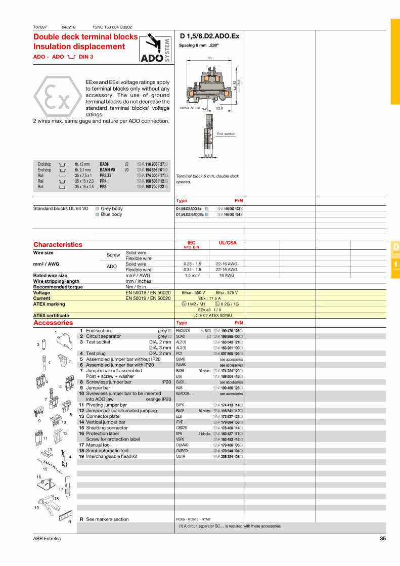
35ABB Entrelec
T07097 040218
D
1
1SNC 160 004 C0202
D 1,5/6.D2.ADO.Ex
D 1,5/6.D2.ADO.ExD 1,5/6.D2.N.ADO.Ex
RC65 - RC610 - RTM7
EExe : 550 V EExi : 375 VEEx : 17.5 A
I M2 / M1 II 2G / 1GEEx e/i I / II
LCIE 02 ATEX 0029U
IEC UL/CSANFC DIN
1.5 mm2 16 AWG
0.28 - 1.5 22-16 AWG0.34 - 1.5 22-16 AWG
R
1
3
4
6
11
8
16
17
9 10
5
2
12
15
18
19
FED2AD2SCADAL2 (1)AL3 (1)FC2BJM6BJMI6BJS6EV6BJE6...BJBBJADO6...
BJP6BJA6EL6ITVECBD2SEP6VSP6OUMADOUPADOUTA14
13
7
Spacing 6 mm .238"
Double deck terminal blocksInsulation displacementADO - ADO DIN 3
EExe and EExi voltage ratings applyto terminal blocks only without anyaccessory. The use of groundterminal blocks do not decrease thestandard terminal blocks' voltageratings.
2 wires max. same gage and nature per ADO connection.
Terminal block 6 mm, double deckopened.
(1) A circuit separator SC.... is required with these accessories.
Type P/N
Standard blocks UL 94 V0 Grey bodyBlue body
Characteristics
Type P/NAccessories
Wire size Solid wireFlexible wire
mm² / AWG Solid wireFlexible wire
Rated wire size mm² / AWGWire stripping length mm / inchesRecommended torque Nm / Ib.inVoltage EN 50019 / EN 50020Current EN 50019 / EN 50020ATEX marking
ATEX certificate
Screw
ADO
End stop th. 12 mm BADH V2End stop th. 9,1 mm BAMH V0 V0Rail 35 x 7,5 x 1 PR3.Z2Rail 35 x 15 x 2,3 PR4Rail 35 x 15 x 1,5 PR5
1 End section grey 2 Circuit separator grey 3 Test socket DIA. 2 mm
DIA. 3 mm4 Test plug DIA. 2 mm5 Assembled jumper bar without IP206 Assembled jumper bar with IP207 Jumper bar not assembled
Post + screw + washer8 Screwless jumper bar IP209 Jumper bar10 Svrewless jumper bar to be inserted
into ADO jaw orange IP2011 Pivoting jumper bar12 Jumper bar for alternated jumping13 Connector plate14 Vertical jumper bar15 Shielding connector16 Protection label
Screw for protection label17 Manual tool18 Semi-automatic tool19 Interchangeable head kit
R See markers section
th. 5
see accessoriessee accessories
20 poles
see accessories
see accessories
10 poles
4 blocks
1SNA 146 062 R23001SNA 146 063 R2400
1SNA 116 900 R27001SNA 194 836 R01001SNA 174 300 R17001SNA 168 500 R12001SNA 168 700 R2200
1SNA 199 476 R25001SNA 196 896 R00001SNA 163 043 R21001SNA 163 261 R00001SNA 007 865 R2600
1SNA 174 784 R20001SNA 168 604 R1600
1SNA 199 466 R2300
1SNA 174 413 R14001SNA 116 541 R12001SNA 173 627 R21001SNA 179 694 R03001SNA 178 408 R14001SNA 163 427 R17001SNA 163 433 R15001SNA 179 466 R06001SNA 178 944 R04001SNA 205 284 R0300
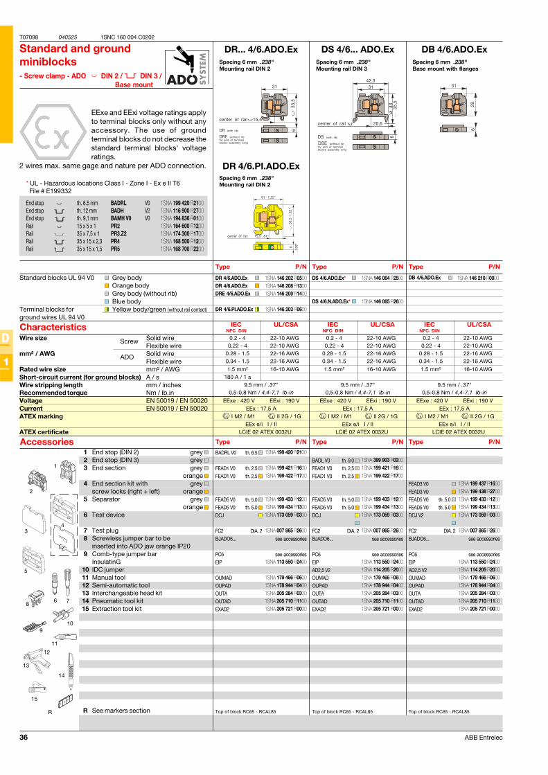
36 ABB Entrelec
T07098 040525
D
1
1SNC 160 004 C0202
DR... 4/6.ADO.Ex
DR 4/6.ADO.ExDR 4/6.ADO.ExDRE 4/6.ADO.Ex
DR 4/6.PI.ADO.Ex
BADRL V0
FEAD1 V0FEAD1 V0
FEAD5 V0FEAD5 V0DCJ
FC2BJADO6...
PC6EIP
OUMADOUPADOUTAOUTADEXAD2
EExe : 420 V EExi : 190 VEEx : 17,5 A
I M2 / M1 II 2G / 1GEEx e/i I / II
LCIE 02 ATEX 0032U
DS 4/6... ADO.Ex
DS 4/6.ADO.Ex*
DS 4/6.N.ADO.Ex*
DB 4/6.ADO.Ex
FEAD3 V0FEAD3 V0FEAD5 V0FEAD5 V0DCJ V2
FC2BJADO6...
PC6EIPAD2,5 V2OUMADOUPADOUTAOUTADEXAD2
EExe : 420 V EExi : 190 VEEx : 17,5 A
I M2 / M1 II 2G / 1GEEx e/i I / II
LCIE 02 ATEX 0032U
EExe : 420 V EExi : 190 VEEx : 17,5 A
I M2 / M1 II 2G / 1GEEx e/i I / II
LCIE 02 ATEX 0032U
BADL V0FEAD1 V0FEAD1 V0
FEAD5 V0FEAD5 V0DCJ
FC2BJADO6...
PC6EIPAD2,5 V2OUMADOUPADOUTAOUTADEXAD2
R
11
12
1
9
2
86
5
7
4
10
13
15
14
3
DB 4/6.ADO.Ex
9.5 mm / .37"0,5-0,8 Nm / 4,4-7,1 Ib-in
IEC UL/CSANFC DIN
1.5 mm2 16-10 AWG
0.2 - 4 22-10 AWG0.22 - 4 22-10 AWG
0.28 - 1.5 22-16 AWG0.34 - 1.5 22-16 AWG
9.5 mm / .37"0,5-0,8 Nm / 4,4-7,1 Ib-in
IEC UL/CSANFC DIN
1.5 mm2 16-10 AWG
0.2 - 4 22-10 AWG0.22 - 4 22-10 AWG
0.28 - 1.5 22-16 AWG0.34 - 1.5 22-16 AWG
9.5 mm / .37"0,5-0,8 Nm / 4,4-7,1 Ib-in
IEC UL/CSANFC DIN
1.5 mm2 16-10 AWG180 A / 1 s
0.2 - 4 22-10 AWG0.22 - 4 22-10 AWG
0.28 - 1.5 22-16 AWG0.34 - 1.5 22-16 AWG
DR 4/6.PI.ADO.Ex
Spacing 6 mm .238"Mounting rail DIN 2
Standard and groundminiblocks- Screw clamp - ADO DIN 2 / DIN 3 /
Base mount
EExe and EExi voltage ratings applyto terminal blocks only without anyaccessory. The use of groundterminal blocks do not decrease thestandard terminal blocks' voltageratings.
2 wires max. same gage and nature per ADO connection.
1 End stop (DIN 2) grey 2 End stop (DIN 3) grey 3 End section grey
orange 4 End section kit with grey
screw locks (right + left) orange 5 Separator grey
orange 6 Test device
7 Test plug8 Screwless jumper bar to be
inserted into ADO jaw orange IP209 Comb-type jumper bar
InsulatinG10 IDC jumper11 Manual tool12 Semi-automatic tool13 Interchangeable head kit14 Pneumatic tool kit15 Extraction tool kit
R See markers section
Type P/N
Standard blocks UL 94 V0 Grey bodyOrange bodyGrey body (without rib)Blue body
Terminal blocks for Yellow body/green (without rail contact)ground wires UL 94 V0
Characteristics
Type P/NAccessories
Wire size Solid wireFlexible wire
mm² / AWG Solid wireFlexible wire
Rated wire size mm² / AWGShort-circuit current (for ground blocks) A / sWire stripping length mm / inchesRecommended torque Nm / Ib.inVoltage EN 50019 / EN 50020Current EN 50019 / EN 50020ATEX marking
ATEX certificate
Spacing 6 mm .238"Mounting rail DIN 3
Type P/N
Type P/N
Spacing 6 mm .238"Base mount with flanges
Type P/N
Type P/N
th. 5.0 th. 5.0
DIA. 2see accessories
see accessories
th. 6.5
th. 2.5 th. 2.5
th. 5.0 th. 5.0
DIA. 2see accessories
see accessories
th. 9.0 th. 2.5 th. 2.5
th. 5.0 th. 5.0
DIA. 2see accessories
see accessories
Top of block RC65 - RCAL85 Top of block RC65 - RCAL85 Top of block RC65 - RCAL85
End stop th. 6.5 mm BADRL V0End stop th. 12 mm BADH V2End stop th. 9,1 mm BAMH V0 V0Rail 15 x 5 x 1 PR2Rail 35 x 7,5 x 1 PR3.Z2Rail 35 x 15 x 2,3 PR4Rail 35 x 15 x 1,5 PR5
Screw
ADO
Spacing 6 mm .238"Mounting rail DIN 2* UL - Hazardous locations Class I - Zone I - Ex e II T6
File # E199332
1SNA 146 202 R05001SNA 146 208 R13001SNA 146 209 R1400
1SNA 146 203 R0600
1SNA 146 064 R2500
1SNA 146 065 R2600
1SNA 199 420 R2100
1SNA 199 421 R16001SNA 199 422 R1700
1SNA 199 433 R12001SNA 199 434 R13001SNA 173 059 R0300
1SNA 007 865 R2600
1SNA 113 550 R2400
1SNA 179 466 R06001SNA 178 944 R04001SNA 205 284 R03001SNA 205 710 R11001SNA 205 721 R0000
1SNA 199 437 R16001SNA 199 438 R27001SNA 199 433 R12001SNA 199 434 R13001SNA 173 059 R0300
1SNA 007 865 R2600
1SNA 113 550 R24001SNA 114 205 R20001SNA 179 466 R06001SNA 178 944 R04001SNA 205 284 R03001SNA 205 710 R11001SNA 205 721 R0000
1SNA 146 210 R0000
1SNA 399 903 R02001SNA 199 421 R16001SNA 199 422 R1700
1SNA 199 433 R12001SNA 199 434 R13001SNA 173 059 R0300
1SNA 007 865 R2600
1SNA 113 550 R24001SNA 114 205 R20001SNA 179 466 R06001SNA 178 944 R04001SNA 205 284 R03001SNA 205 710 R11001SNA 205 721 R0000
1SNA 199 420 R21001SNA 116 900 R27001SNA 194 836 R01001SNA 164 600 R12001SNA 174 300 R17001SNA 168 500 R12001SNA 168 700 R2200
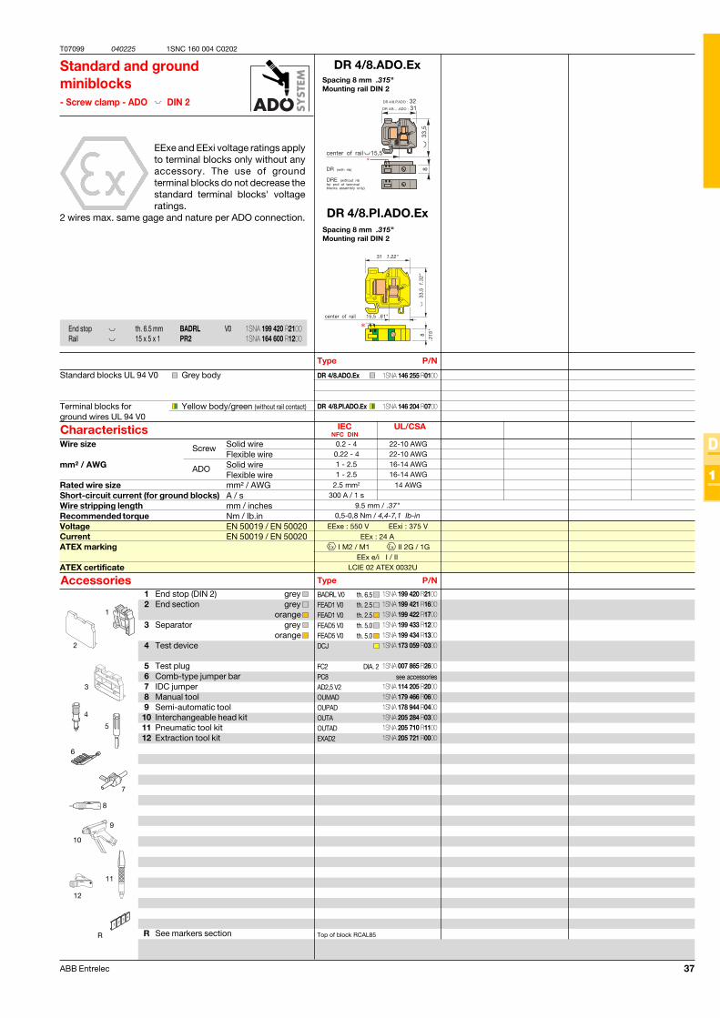
37ABB Entrelec
T07099 040225
D
1
1SNC 160 004 C0202
DR 4/8.PI.ADO.Ex
DR 4/8.ADO.Ex
DR 4/8.PI.ADO.Ex
BADRL V0FEAD1 V0FEAD1 V0FEAD5 V0FEAD5 V0DCJ
FC2PC8AD2,5 V2OUMADOUPADOUTAOUTADEXAD2
EExe : 550 V EExi : 375 VEEx : 24 A
I M2 / M1 II 2G / 1GEEx e/i I / II
LCIE 02 ATEX 0032U
R
11
12
1
9
2
8
6
5
7
4
10
3
9.5 mm / .37"0,5-0,8 Nm / 4,4-7,1 Ib-in
IEC UL/CSANFC DIN
2.5 mm2 14 AWG300 A / 1 s
0.2 - 4 22-10 AWG0.22 - 4 22-10 AWG1 - 2.5 16-14 AWG1 - 2.5 16-14 AWG
DR 4/8.ADO.Ex
Spacing 8 mm .315"Mounting rail DIN 2
Standard and groundminiblocks- Screw clamp - ADO DIN 2
EExe and EExi voltage ratings applyto terminal blocks only without anyaccessory. The use of groundterminal blocks do not decrease thestandard terminal blocks' voltageratings.
2 wires max. same gage and nature per ADO connection.
1 End stop (DIN 2) grey 2 End section grey
orange 3 Separator grey
orange 4 Test device
5 Test plug6 Comb-type jumper bar7 IDC jumper8 Manual tool9 Semi-automatic tool10 Interchangeable head kit11 Pneumatic tool kit12 Extraction tool kit
R See markers section
Type P/N
Standard blocks UL 94 V0 Grey body
Terminal blocks for Yellow body/green (without rail contact)ground wires UL 94 V0
Characteristics
Type P/NAccessories
Wire size Solid wireFlexible wire
mm² / AWG Solid wireFlexible wire
Rated wire size mm² / AWGShort-circuit current (for ground blocks) A / sWire stripping length mm / inchesRecommended torque Nm / Ib.inVoltage EN 50019 / EN 50020Current EN 50019 / EN 50020ATEX marking
ATEX certificate
th. 6.5 th. 2.5 th. 2.5 th. 5.0 th. 5.0
DIA. 2see accessories
Top of block RCAL85
Screw
ADO
End stop th. 6.5 mm BADRL V0Rail 15 x 5 x 1 PR2
Spacing 8 mm .315"Mounting rail DIN 2
1SNA 199 420 R21001SNA 199 421 R16001SNA 199 422 R17001SNA 199 433 R12001SNA 199 434 R13001SNA 173 059 R0300
1SNA 007 865 R2600
1SNA 114 205 R20001SNA 179 466 R06001SNA 178 944 R04001SNA 205 284 R03001SNA 205 710 R11001SNA 205 721 R0000
1SNA 199 420 R21001SNA 164 600 R1200
1SNA 146 255 R0100
1SNA 146 204 R0700
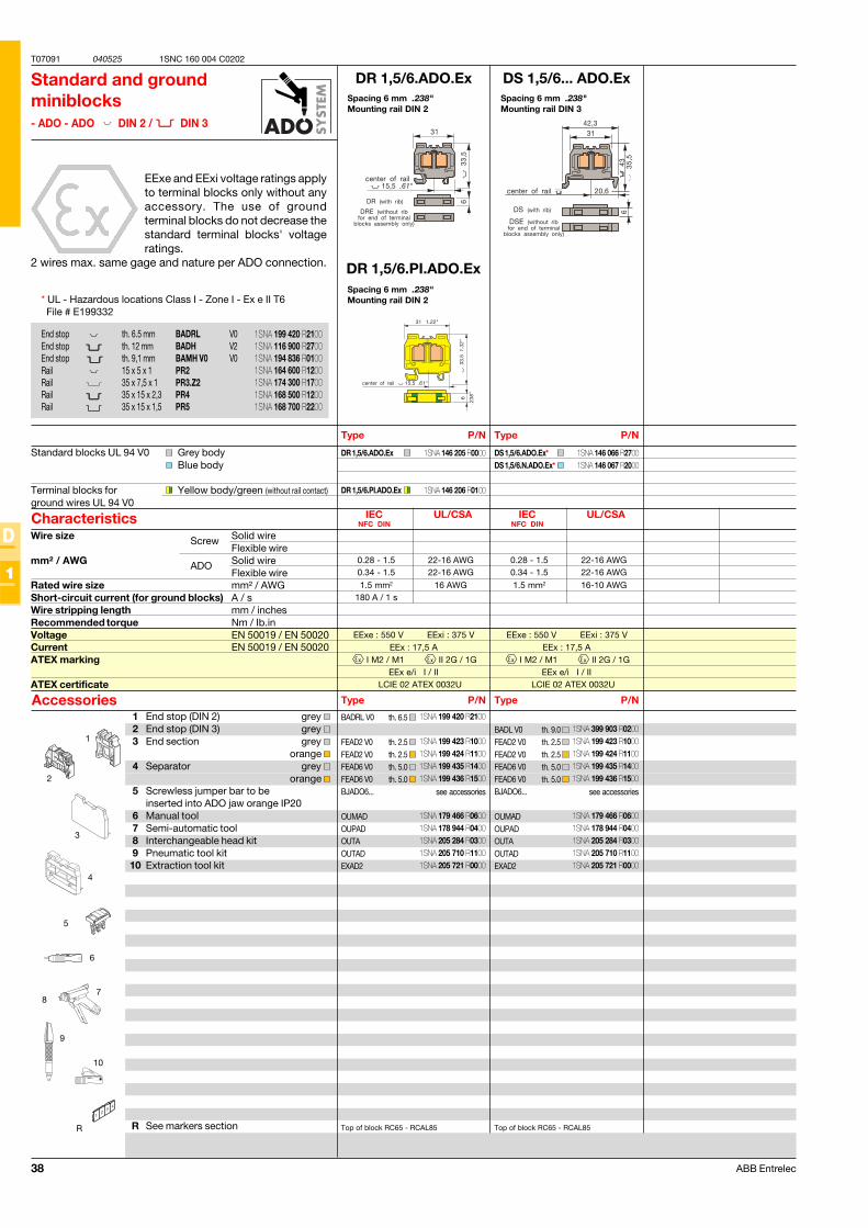
38 ABB Entrelec
T07091 040525
D
1
1SNC 160 004 C0202
DR 1,5/6.ADO.Ex
DR 1,5/6.ADO.Ex
DR 1,5/6.PI.ADO.Ex
BADRL V0
FEAD2 V0FEAD2 V0FEAD6 V0FEAD6 V0BJADO6...
OUMADOUPADOUTAOUTADEXAD2
EExe : 550 V EExi : 375 VEEx : 17,5 A
I M2 / M1 II 2G / 1GEEx e/i I / II
LCIE 02 ATEX 0032U
DS 1,5/6... ADO.Ex
DS 1,5/6.ADO.Ex*DS 1,5/6.N.ADO.Ex*
EExe : 550 V EExi : 375 VEEx : 17,5 A
I M2 / M1 II 2G / 1GEEx e/i I / II
LCIE 02 ATEX 0032U
BADL V0FEAD2 V0FEAD2 V0FEAD6 V0FEAD6 V0BJADO6...
OUMADOUPADOUTAOUTADEXAD2
R
1
9
2
8
6
5
7
4
10
3
IEC UL/CSANFC DIN
1.5 mm2 16-10 AWG
0.28 - 1.5 22-16 AWG0.34 - 1.5 22-16 AWG
IEC UL/CSANFC DIN
1.5 mm2 16 AWG180 A / 1 s
0.28 - 1.5 22-16 AWG0.34 - 1.5 22-16 AWG
DR 1,5/6.PI.ADO.Ex
Spacing 6 mm .238"Mounting rail DIN 2
Standard and groundminiblocks- ADO - ADO DIN 2 / DIN 3
EExe and EExi voltage ratings applyto terminal blocks only without anyaccessory. The use of groundterminal blocks do not decrease thestandard terminal blocks' voltageratings.
2 wires max. same gage and nature per ADO connection.
1 End stop (DIN 2) grey 2 End stop (DIN 3) grey 3 End section grey
orange 4 Separator grey
orange 5 Screwless jumper bar to be
inserted into ADO jaw orange IP206 Manual tool7 Semi-automatic tool8 Interchangeable head kit9 Pneumatic tool kit10 Extraction tool kit
R See markers section
Type P/N
Standard blocks UL 94 V0 Grey bodyBlue body
Terminal blocks for Yellow body/green (without rail contact)ground wires UL 94 V0
Characteristics
Type P/NAccessories
Wire size Solid wireFlexible wire
mm² / AWG Solid wireFlexible wire
Rated wire size mm² / AWGShort-circuit current (for ground blocks) A / sWire stripping length mm / inchesRecommended torque Nm / Ib.inVoltage EN 50019 / EN 50020Current EN 50019 / EN 50020ATEX marking
ATEX certificate
Spacing 6 mm .238"Mounting rail DIN 3
Type P/N
Type P/N
th. 6.5
th. 2.5 th. 2.5 th. 5.0 th. 5.0
see accessories
th. 9.0 th. 2.5 th. 2.5 th. 5.0 th. 5.0
see accessories
Top of block RC65 - RCAL85 Top of block RC65 - RCAL85
End stop th. 6.5 mm BADRL V0End stop th. 12 mm BADH V2End stop th. 9,1 mm BAMH V0 V0Rail 15 x 5 x 1 PR2Rail 35 x 7,5 x 1 PR3.Z2Rail 35 x 15 x 2,3 PR4Rail 35 x 15 x 1,5 PR5
Screw
ADO
Spacing 6 mm .238"Mounting rail DIN 2* UL - Hazardous locations Class I - Zone I - Ex e II T6
File # E199332
1SNA 146 205 R0000
1SNA 146 206 R0100
1SNA 146 066 R27001SNA 146 067 R2000
1SNA 199 420 R2100
1SNA 199 423 R10001SNA 199 424 R11001SNA 199 435 R14001SNA 199 436 R1500
1SNA 179 466 R06001SNA 178 944 R04001SNA 205 284 R03001SNA 205 710 R11001SNA 205 721 R0000
1SNA 399 903 R02001SNA 199 423 R10001SNA 199 424 R11001SNA 199 435 R14001SNA 199 436 R1500
1SNA 179 466 R06001SNA 178 944 R04001SNA 205 284 R03001SNA 205 710 R11001SNA 205 721 R0000
1SNA 199 420 R21001SNA 116 900 R27001SNA 194 836 R01001SNA 164 600 R12001SNA 174 300 R17001SNA 168 500 R12001SNA 168 700 R2200
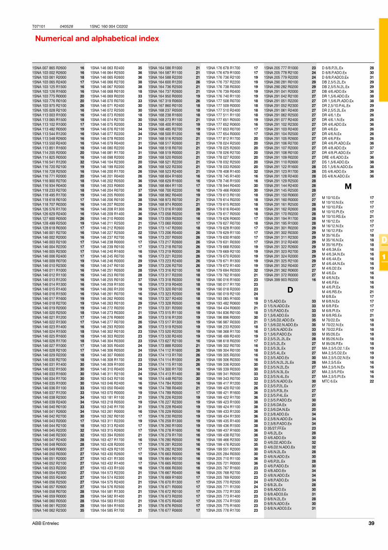
39ABB Entrelec
T07101 040528
D
1
1SNC 160 004 C0202
Numerical and alphabetical index
1SNA 007 865 R2600 161SNA 103 002 R2600 161SNA 103 061 R2000 181SNA 103 065 R2400 171SNA 103 125 R1500 161SNA 103 126 R1600 161SNA 103 775 R0000 201SNA 103 776 R0100 201SNA 103 975 R2100 261SNA 105 028 R2100 161SNA 113 003 R1000 161SNA 113 065 R1500 181SNA 113 102 R1000 171SNA 113 482 R0500 191SNA 113 544 R1200 161SNA 113 548 R2600 161SNA 113 550 R2400 161SNA 113 851 R1600 181SNA 114 205 R2000 201SNA 114 825 R0500 161SNA 116 541 R1200 321SNA 116 720 R2100 191SNA 116 728 R2500 161SNA 116 771 R2000 201SNA 116 900 R2700 181SNA 116 934 R0400 181SNA 118 233 R2700 181SNA 118 495 R1700 191SNA 118 618 R0100 171SNA 118 707 R0300 161SNA 126 576 R1700 161SNA 126 629 R2400 161SNA 127 600 R0500 261SNA 128 499 R2500 191SNA 128 618 R0300 171SNA 146 001 R2700 161SNA 146 002 R2000 161SNA 146 003 R2100 171SNA 146 004 R2200 171SNA 146 005 R2300 171SNA 146 006 R2400 171SNA 146 009 R0700 191SNA 146 010 R2300 161SNA 146 011 R1000 161SNA 146 012 R1100 161SNA 146 013 R1200 161SNA 146 014 R1300 161SNA 146 015 R1400 161SNA 146 016 R1500 161SNA 146 017 R1600 191SNA 146 018 R2700 191SNA 146 019 R2000 191SNA 146 020 R2500 181SNA 146 021 R1200 171SNA 146 022 R1300 171SNA 146 023 R1400 161SNA 146 024 R1500 181SNA 146 025 R1600 181SNA 146 026 R1700 181SNA 146 027 R1000 171SNA 146 028 R2100 171SNA 146 029 R2200 181SNA 146 030 R2700 181SNA 146 031 R1400 301SNA 146 032 R1500 301SNA 146 033 R1600 301SNA 146 034 R1700 301SNA 146 035 R1000 301SNA 146 036 R1100 331SNA 146 037 R1200 331SNA 146 038 R2300 341SNA 146 039 R2400 341SNA 146 040 R0100 331SNA 146 041 R2600 341SNA 146 042 R2700 301SNA 146 043 R2000 171SNA 146 044 R2100 181SNA 146 045 R2200 321SNA 146 046 R2300 321SNA 146 047 R2400 281SNA 146 048 R0500 281SNA 146 049 R0600 271SNA 146 050 R0300 271SNA 146 051 R2000 271SNA 146 052 R2100 271SNA 146 053 R2200 271SNA 146 054 R2300 271SNA 146 055 R2400 271SNA 146 056 R2500 271SNA 146 057 R2600 271SNA 146 058 R0700 281SNA 146 059 R0000 281SNA 146 060 R0500 281SNA 146 061 R2200 281SNA 146 062 R2300 35
1SNA 146 063 R2400 351SNA 146 064 R2500 361SNA 146 065 R2600 361SNA 146 066 R2700 381SNA 146 067 R2000 381SNA 146 068 R0100 181SNA 146 069 R0200 331SNA 146 070 R0700 331SNA 146 071 R2400 301SNA 146 072 R2500 301SNA 146 073 R2600 181SNA 146 074 R2700 301SNA 146 075 R2000 331SNA 146 076 R2100 341SNA 146 077 R2200 341SNA 146 078 R0300 311SNA 146 079 R0400 311SNA 146 080 R2200 341SNA 146 081 R1700 311SNA 146 098 R2000 201SNA 146 104 R2300 201SNA 146 199 R2200 261SNA 146 200 R1700 261SNA 146 201 R0400 261SNA 146 202 R0500 361SNA 146 203 R0600 361SNA 146 204 R0700 371SNA 146 205 R0000 381SNA 146 206 R0100 381SNA 146 207 R0200 291SNA 146 208 R1300 361SNA 146 209 R1400 361SNA 146 210 R0000 361SNA 146 211 R2500 211SNA 146 212 R2600 211SNA 146 227 R2500 221SNA 146 237 R2700 161SNA 146 238 R0000 171SNA 146 239 R0100 171SNA 146 240 R1600 161SNA 146 245 R0700 161SNA 146 246 R0000 291SNA 146 247 R0100 291SNA 146 251 R0500 281SNA 146 253 R0700 281SNA 146 255 R0100 371SNA 146 259 R1500 161SNA 146 260 R1200 191SNA 146 261 R0700 161SNA 146 262 R0000 161SNA 146 263 R0100 291SNA 146 272 R0200 211SNA 146 273 R0300 211SNA 146 276 R0600 261SNA 146 277 R0700 261SNA 146 293 R2000 261SNA 146 302 R0100 231SNA 146 303 R0200 231SNA 146 304 R0300 231SNA 146 305 R0400 241SNA 146 306 R0500 241SNA 146 307 R0600 231SNA 146 308 R1700 231SNA 146 309 R1000 231SNA 146 310 R0400 241SNA 146 311 R2100 241SNA 163 043 R2100 161SNA 163 046 R2400 161SNA 163 050 R0400 161SNA 163 070 R0000 191SNA 163 181 R1100 211SNA 163 218 R0500 191SNA 163 240 R1700 311SNA 163 261 R0000 161SNA 163 262 R0100 171SNA 163 311 R2200 191SNA 163 313 R2400 171SNA 163 315 R2600 171SNA 163 394 R2600 211SNA 163 427 R1700 161SNA 163 428 R2000 171SNA 163 429 R2100 171SNA 163 430 R2600 171SNA 163 431 R1300 181SNA 163 432 R1400 171SNA 163 433 R1500 161SNA 164 573 R2200 211SNA 164 574 R2300 211SNA 164 575 R2400 211SNA 164 576 R2500 211SNA 164 581 R1300 211SNA 164 582 R1400 211SNA 164 583 R1500 211SNA 164 584 R1600 211SNA 164 585 R1700 21
1SNA 164 586 R1000 211SNA 164 587 R1100 211SNA 164 588 R2200 211SNA 164 600 R1200 261SNA 164 736 R2500 211SNA 164 737 R2600 211SNA 164 950 R0000 191SNA 167 319 R0600 261SNA 167 860 R0100 181SNA 168 237 R0500 181SNA 168 238 R1600 181SNA 168 273 R1100 211SNA 168 400 R1600 191SNA 168 485 R2700 191SNA 168 500 R1200 161SNA 168 516 R2500 211SNA 168 517 R2600 211SNA 168 518 R0700 211SNA 168 519 R0000 211SNA 168 520 R0500 211SNA 168 521 R2200 211SNA 168 522 R2300 211SNA 168 523 R2400 211SNA 168 604 R1600 161SNA 168 629 R1600 161SNA 168 664 R1100 171SNA 168 700 R2200 161SNA 168 962 R0400 191SNA 168 973 R0700 211SNA 168 974 R0000 211SNA 173 016 R1000 261SNA 173 058 R0200 191SNA 173 059 R0300 161SNA 173 060 R0000 171SNA 173 147 R2000 181SNA 173 206 R0400 261SNA 173 207 R0500 261SNA 173 217 R2600 261SNA 173 218 R0700 261SNA 173 219 R0000 261SNA 173 221 R2200 261SNA 173 223 R2400 261SNA 173 226 R2700 261SNA 173 316 R2100 181SNA 173 317 R2200 181SNA 173 318 R0300 181SNA 173 319 R0400 181SNA 173 320 R0100 181SNA 173 323 R2000 181SNA 173 327 R2400 181SNA 173 328 R0500 181SNA 173 331 R2000 181SNA 173 515 R1100 191SNA 173 516 R1200 191SNA 173 517 R1300 191SNA 173 519 R2500 191SNA 173 520 R2200 191SNA 173 530 R2400 191SNA 173 627 R2100 161SNA 173 888 R2000 211SNA 174 112 R1600 261SNA 174 113 R1700 261SNA 174 114 R1000 261SNA 174 115 R1100 261SNA 174 300 R1700 161SNA 174 413 R1400 301SNA 174 448 R0700 301SNA 174 784 R2000 161SNA 174 788 R0400 211SNA 174 789 R0500 171SNA 176 226 R2200 191SNA 176 227 R2300 191SNA 176 228 R0400 191SNA 176 229 R0500 191SNA 176 230 R0200 191SNA 176 259 R1300 191SNA 176 260 R1000 191SNA 176 278 R1600 161SNA 176 279 R1700 161SNA 176 280 R0500 161SNA 176 281 R2200 161SNA 176 282 R2300 161SNA 176 663 R0000 161SNA 176 664 R0100 161SNA 176 665 R0200 161SNA 176 666 R0300 161SNA 176 667 R0400 161SNA 176 669 R1600 171SNA 176 670 R1300 171SNA 176 671 R0000 171SNA 176 672 R0100 171SNA 176 673 R0200 171SNA 176 675 R0400 171SNA 176 676 R0500 171SNA 176 677 R0600 17
1SNA 176 678 R1700 171SNA 176 679 R1000 171SNA 176 736 R2100 191SNA 176 737 R2200 191SNA 176 738 R0300 191SNA 176 739 R0400 191SNA 176 740 R1100 191SNA 177 508 R0700 181SNA 177 509 R0000 181SNA 177 510 R2400 181SNA 177 511 R1100 181SNA 177 651 R0500 191SNA 177 652 R0600 161SNA 177 653 R0700 171SNA 177 654 R0000 171SNA 177 812 R1700 201SNA 178 024 R2500 201SNA 178 025 R2600 201SNA 178 026 R2700 201SNA 178 027 R2000 201SNA 178 032 R2500 201SNA 178 033 R2600 201SNA 178 408 R1400 321SNA 178 745 R1400 161SNA 178 746 R1500 161SNA 178 944 R0400 301SNA 179 466 R0600 301SNA 179 613 R0100 181SNA 179 614 R0200 181SNA 179 615 R0300 181SNA 179 616 R0400 181SNA 179 617 R0500 181SNA 179 626 R0600 171SNA 179 627 R0700 181SNA 179 628 R1000 171SNA 179 629 R1100 171SNA 179 630 R1600 171SNA 179 631 R0300 171SNA 179 668 R2000 191SNA 179 669 R2100 191SNA 179 670 R2600 191SNA 179 671 R1300 191SNA 179 672 R1400 191SNA 179 694 R0300 321SNA 179 762 R1600 211SNA 190 016 R1600 231SNA 190 017 R1700 231SNA 190 018 R2000 231SNA 190 019 R2100 241SNA 193 065 R1600 181SNA 193 482 R0600 191SNA 194 434 R0600 211SNA 194 836 R0100 181SNA 196 896 R0000 301SNA 196 987 R0300 211SNA 198 233 R2000 181SNA 198 368 R1700 161SNA 198 499 R2400 191SNA 198 618 R0200 171SNA 199 302 R0700 161SNA 199 304 R0100 181SNA 199 305 R0200 161SNA 199 306 R0300 161SNA 199 336 R2000 301SNA 199 339 R0300 301SNA 199 341 R0500 331SNA 199 343 R0700 331SNA 199 417 R1200 321SNA 199 420 R2100 261SNA 199 421 R1600 361SNA 199 422 R1700 361SNA 199 423 R1000 381SNA 199 424 R1100 381SNA 199 433 R1200 361SNA 199 434 R1300 361SNA 199 435 R1400 381SNA 199 436 R1500 381SNA 199 437 R1600 361SNA 199 438 R2700 361SNA 199 466 R2300 321SNA 199 476 R2500 351SNA 199 551 R2000 301SNA 205 284 R0300 301SNA 205 710 R1100 361SNA 205 721 R0000 361SNA 205 767 R1600 231SNA 205 768 R2700 231SNA 205 769 R2000 231SNA 205 770 R2500 241SNA 205 771 R1200 241SNA 205 772 R1300 231SNA 205 773 R1400 231SNA 205 774 R1500 231SNA 205 775 R1600 231SNA 205 776 R1700 23
1SNA 205 777 R1000 231SNA 205 778 R2100 241SNA 205 779 R2200 241SNA 290 281 R0100 291SNA 290 282 R0200 291SNA 291 041 R2000 271SNA 291 042 R2100 271SNA 291 051 R2200 271SNA 291 052 R2300 271SNA 291 061 R2400 271SNA 291 062 R2500 271SNA 291 077 R2400 271SNA 291 102 R2300 271SNA 291 103 R2400 271SNA 291 104 R2500 271SNA 291 105 R2600 271SNA 291 106 R2700 271SNA 291 107 R2000 271SNA 291 108 R0100 271SNA 291 109 R0200 271SNA 291 110 R2600 271SNA 291 122 R1600 281SNA 291 123 R1700 281SNA 291 128 R2400 281SNA 291 129 R2500 281SNA 291 144 R2400 281SNA 291 145 R2500 281SNA 291 150 R0600 271SNA 291 160 R0000 271SNA 291 161 R2500 281SNA 291 162 R2600 281SNA 291 170 R0200 281SNA 291 194 R1700 281SNA 291 195 R1000 281SNA 291 301 R0200 291SNA 291 302 R0300 291SNA 291 311 R2300 291SNA 291 312 R2400 291SNA 291 322 R2600 291SNA 291 323 R2700 291SNA 291 324 R2000 291SNA 291 325 R2100 291SNA 291 352 R0400 271SNA 291 362 R0600 271SNA 291 372 R0000 271SNA 399 903 R0200 16
DD 1/5.ADO.Ex 33D 1/5.N.ADO.Ex 33D 1/5.P.ADO.Ex 33D 1,5/6.ADO.Ex 33D 1,5/6.D2.ADO.Ex 35D 1,5/6.D2.N.ADO.Ex 35D 1,5/6.N.ADO.Ex 33D 1,5/6.P.ADO.Ex 33D 2,5/5.2L.2L.Ex 28D 2,5/5.2L.Ex 27D 2,5/5.3L.Ex 27D 2,5/5.4L.Ex 27D 2,5/5.ADO.Ex 30D 2,5/5.N.2L.2L.Ex 28D 2,5/5.N.2L.Ex 27D 2,5/5.N.3L.Ex 27D 2,5/5.N.4L.Ex 27D 2,5/5.N.ADO.Ex 30D 2,5/5.P.2L.Ex 27D 2,5/5.P.3L.Ex 27D 2,5/5.P.4L.Ex 27D 2,5/5.P.ADO.Ex 30D 2,5/6.DA.Ex 20D 2,5/6.DA.N.Ex 20D 2,5/8.ADO.Ex 34D 2,5/8.N.ADO.Ex 34D 2,5/8.P.ADO.Ex 34D 35/27.FF.Ex 23D 4/6.2L.Ex 28D 4/6.ADO.Ex 30D 4/6.D2.ADO.Ex 32D 4/6.D2.N.ADO.Ex 32D 4/6.N.2L.Ex 28D 4/6.N.ADO.Ex 30D 4/6.P.2L.Ex 28D 4/6.P.ADO.Ex 30D 4/8.ADO.Ex 34D 4/8.N.ADO.Ex 34D 4/8.P.ADO.Ex 34D 6/8.2L.Ex 28D 6/8.ADO.Ex 30D 6/8.ADO3.Ex 31D 6/8.N.2L.Ex 28D 6/8.N.ADO.Ex 30D 6/8.N.ADO3.Ex 31
D 6/8.P.2L.Ex 28D 6/8.P.ADO.Ex 30D 6/8.P.ADO3.Ex 31DB 2,5/5.2L.Ex 29DB 2,5/5.N.2L.Ex 29DB 4/6.ADO.Ex 36DR 1,5/6.ADO.Ex 38DR 1,5/6.PI.ADO.Ex 38DR 2,5/10.P.4L.Ex 29DR 2,5/5.2L.Ex 29DR 4/6.1.Ex 26DR 4/6.1.N.Ex 26DR 4/6.ADO.Ex 36DR 4/6.Ex 26DR 4/6.N.Ex 26DR 4/6.P.Ex 26DR 4/6.PI.ADO.Ex 36DR 4/8.ADO.Ex 37DR 4/8.PI.ADO.Ex 37DRE 4/6.ADO.Ex 36DS 1,5/6.ADO.Ex 38DS 1,5/6.N.ADO.Ex 38DS 4/6.ADO.Ex 36DS 4/6.N.ADO.Ex 36
MM 10/10.Ex 17M 10/10.N.Ex 17M 10/10.P.Ex 17M 10/10.PI.Ex 17M 10/10.RS.Ex 21M 16/12.Ex 17M 16/12.N.Ex 17M 16/12.P.Ex 17M 35/16.Ex 18M 35/16.N.Ex 18M 35/16.P.Ex 18M 4/6.3A.Ex 16M 4/6.3A.N.Ex 16M 4/6.4A.Ex 16M 4/6.4A.N.Ex 16M 4/6.D2.Ex 19M 4/6.Ex 16M 4/6.N.Ex 16M 4/6.P.Ex 16M 4/6.PI.Ex 16M 4/6.RS.Ex 21M 6/8.Ex 17M 6/8.N.Ex 17M 6/8.P.Ex 17M 6/8.PI.Ex 17M 6/8.RS.Ex 21M 70/22.Ex 18M 70/22.N.Ex 18M 70/22.P.Ex 18M 95/26.Ex 18M 95/26.N.Ex 18M 95/26.P.Ex 18MA 2,5/5.D2.1.Ex 19MA 2,5/5.D2.Ex 19MA 2,5/5.D2.N.Ex 19MA 2,5/5.Ex 16MA 2,5/5.N.Ex 16MA 2,5/5.P.Ex 16MA 2,5/5.PI.Ex 16MTC 6.Ex 22

Pub
licat
ion
N°
: 1S
NC
160
004
C02
02
ABB EntrelecConnection Department184, rue Léon BlumF - 69627 Villeurbanne cedex / France
As part of its on-going product improvement, ABB Entrelecreserves the right to modify the characteristics or theproducts described in this document. The informationgiven is not-contractual. For further details pleasecontact the ABB Entrelec company marketing theseproducts in your country.
ABB EntrelecExport Sales Department10 rue Ampère Z.I. - B.P. 114F - 69685 Chassieu cedex / FranceTel. : +33 (0) 4 7222 1722Fax. : +33 (0) 4 7222 1935www.abb.fr/entrelec