Embed Size (px)
Citation preview

www.toptica.com 1
Terahertz TechnologiesSystems and Accessories
Plastic Inspection
Paint and Coating Layers
Industrial Quality Control
Non-Destructive Testing
Material Research
Gas Sensing
Metamaterials and Micro-Optics
Fundamental Physics

Introduction
Terahertz Applications
Plastic Inspection
Paint Layers
Industrial Quality Control
Non-Destructive Testing
Material Research
Gas Sensing
Fundamental Physics
Time-Domain Terahertz Generation
Frequency-Domain Terahertz Generation
Product Overview
TeraFlash
Imaging Extension
TeraSpeed
Photoconductive Switches
Customized Systems
TeraScan 780 / 1550
TeraBeam 780 / 1550
Tuning Range Extension
Phase Modulation Extension
Photomixers
Accessories – Schottky Receivers
Accessories – Optomechanics
Time-Domain vs. Frequency-Domain
Order Information
3
4
4
5
5
6
6
7
7
8
9
10
12
14
15
16
17
18
20
21
22
23
24
25
26
27
Contents

www.toptica.com 3
Between Microwaves & InfraredThe terahertz range refers to electroma-
gnetic waves with frequencies between
100 GHz and 10 THz, or wavelengths
between 3 mm and 30 μm. Light bet-
ween microwaves and infrared has some
unique properties. Terahertz waves can
“look inside” plastics and textiles, paper
and cardboard. Many biomolecules, pro-
teins, explosives and narcotics also feature
characteristic absorption lines – so-called
spectral “fingerprints” – at terahertz fre-
quencies. Unlike X-rays, terahertz waves
do not have any ionizing effect and are ge-
nerally considered biologically innocuous.
Closing the Terahertz GapFor a long time, it has been difficult to
generate intensive, directional terahertz
radiation, and the terahertz range was
considered the final frontier of the elec-
tromagnetic spectrum. Now, frequencies
between 0.5 and 10 THz have become the
domain of laser-based techniques. Opto-
electronic approaches use either femto-
second lasers or tunable diode lasers.
Photomixers, photoconductive switches
or nonlinear crystals convert the near-
infrared laser light into terahertz waves,
either broadband or spectrally resolved.
The terahertz gap is bridged at last.
The Complete PortfolioOwing to a long-standing background
in diode and fiber laser technologies,
TOPTICA has become one of the most
successful suppliers of terahertz instru-
mentation world-wide. Our ultrafast fiber
lasers form the basis of the time-domain
systems TeraFlash and TeraSpeed, and
precisely tunable diode lasers lie at the
heart of the frequency-domain platform
TeraScan. In more than 30 countries
around the globe, TOPTICA’s terahertz
customers engage in fields as diverse
as trace-gas sensing and low-tempera-
ture physics, the development of meta-
materials and micro-optics, material in-
spection, layer thickness measurement
and terahertz communication.
Applications
› Plastic Inspection
› Paint and Coating Layers
› Industrial Quality Control
› Non-Destructive Testing
› Material Research
› Gas Sensing
› Hydration Monitoring
› Ultrafast Dynamics
› Communication
› Metamaterials and Micro-Optics
› Fundamental Physics
Wavelength [m]
10-10 10-9 10-8 10-7 10-6 10-5 10-4 10-3 10-2 10-1 100 101
Frequency [Hz]
1018 1017 1016 1015 1014 1013 1012 1011 1010 109 108 107
X-Rays Ultraviolet InfraredTerahertz
Microwaves Radio WavesVIS
Terahertz WavesThe Final Frontier of the Electromagnetic Spectrum

www.toptica.com4
TERAHERTZ APPLICATIONS
Plastic InspectionAccurate thickness measurements play an
increasingly important role in the produc-
tion of extruded polymers: Plastic pipes
and bottles require a minimum wall thick-
ness for mechanical stability, yet material
costs increase drastically once the layers
become too thick. A variety of conventio-
nal techniques exist, including ultrasonic
testing, x-ray CT, magnetic gauges and
eddy-current measurements. However,
Pulse trace obtained with TOPTICA’s TeraFlash and a piece of high-density polyethylene. The pulse spacing of 8.60 ps corresponds to a wall thickness of 843 μm.
∆ t = 8.60 psLayer thickness = 843 µm
-20
-10
0
10
20
Am
plitu
de (n
A)
0 10Time (ps)
they all face challenges: either in terms of
radiation hazards, or contact media re-
quired, or they are limited with respect to
depth resolution and measurement speed.
Many polymer materials, though optical-
ly opaque, exhibit a pronounced low ab-
sorption at terahertz frequencies. Pulsed
terahertz radiation can thus provide infor-
mation of an object’s thickness, even in
multi-layered samples, via time-of-flight
techniques: Each layer interface reflects
a part of the incident pulse, and the time
elapsed between the arrivals of pulse
“echoes” from either side is directly propor-
tional to the optical thickness of that layer.
Applications of terahertz radiation in thick-
ness profilometry are not limited to extru-
ded polymers though: In chip production,
polymer coatings shield the semiconductor
from moisture, dust and mechanical stress.
In jet engines, ceramic thermal-barrier coa-
tings protect turbine components from high
temperatures and wear. The majority of
coating materials are sufficiently transpa-
rent for terahertz light to enable contact-
free thickness measurements.

www.toptica.com 5
Paint LayersMeasuring the thickness of paint layers
forms an important step in automotive
manufacturing. The layers not only give
a vehicle its color, but also provide pro-
tection against scratches, corrosion and
chemicals. Therefore, color pigments,
smoothing “primers” and protective
Pulse echoes of a carbon-fiber-reinforced polymer substrate with three different coating layers. The arrows indicate the reflections at the respective interfaces.
coatings all cover a substrate made of
steel or carbon-fiber composites, with
each layer having a thickness of a few ten
microns only.
Most of the traditional thickness gauges
require physical contact to the layer under
-100
-50
0
50
100
150
Am
plitu
de (n
A)
0 10 20 30 40 50 60 70
Time (ps)
3 layers on CFRP
Top: 84.6 µmCenter: 40.6 µmBottom: 48.3 µm
test, and fail in case of non-metallic subst-
rates. Terahertz pulses, by contrast, resol-
ve the thickness of each individual layer,
as long as adjacent coatings differ in their
refractive index.
Layer thickness analysis combines time-
of-flight measurements of terahertz pulse
echoes with elaborate data post-proces-
sing, which involves time-trace simulations
and advanced fitting routines. This method
has proven successful: TOPTICA’s custo-
mers have achieved thickness measure-
ments down to 10-20 μm, with accuracies
on the single-micron level.
0 5 10 15 20 250
5
10
15
20
RM
S S
igna
l (dB
)
Time (ms)
Industrial Quality Control Applications in quality and process control
take advantage of terahertz systems that
are inherently safe, work in a contact-free
manner and achieve a very high measu-
rement speed. The latter aspect becomes
particularly relevant if the task involves
rapidly moving samples, e.g., if items on
1D-scan of folded cardboard boxes with and without a package slip. The graph shows the transmitted terahertz intensity while the boxes moved at a velocity of 21 m/s. In the example, the TeraSpeed recorded more than 150,000 intensity values per second.
fast conveyor belts need to be screened
with single-millimeter resolution.
One emerging application is quality con-
trol of folded cardboard boxes used for
packaging pharmaceuticals. European
legislation dictates that pharmaceuticals
may only be sold with patient information
leaflets enclosed. While this requirement
necessitates “100 % inspection”, pre-
sent-day techniques still rely on weighing
large batches of boxes, a method that pro-
vides integral values only.
In proof-of-principle measurements,
TOPTICA’s researchers showed that fast
terahertz screening detected the presence
or absence of a package insert unambi-
guously. The method succeeded even for
samples moving at more than 20 meters
per second, and for boxes that overlapped
in a tile-like manner.

www.toptica.com6
Non-Destructive Testing Terahertz systems offer a unique com-
bination of imaging and spectroscopic
methods. Terahertz waves penetrate ma-
terials like plastics, paper and – to some
extent – textiles. They can thus reveal the
presence of concealed objects, e.g., in
Photograph and overlay terahertz image of a plastic step-wedge with two sub-surface voids.
mail envelopes, and identify the material in
question using spectroscopic techniques.
Pulsed terahertz radiation not only measu-
res an object’s reflectance, transmittance
or chemical composition, but also probes
its depth profile. Scanning a sample
with the help of a terahertz beam then
generates a three-dimensional image that
pinpoints sub-surface cracks, voids and
delaminations.
The liquid state of water generally provides
a stark contrast in terahertz imaging – a
property exploited in humidity measure-
ments in paper production lines. Water
contrast terahertz imaging can help to
avoid drought stress and optimize irriga-
tion strategy by monitoring plant leaves.
This is a topic of relevance for agricultural
crops in arid regions where desertifica-
tion and water shortages present serious
threats.
Material ResearchTerahertz spectroscopy helps uncover
the properties of a variety of substances.
Refractive-index measurements comple-
ment the information gained from ampli-
tude data: In polymers, the variation of
the refractive index with temperature re-
veals minute structural changes. For fiber-
Transmitted terahertz signal during the cu-ring process of a two-component adhesive (black curve) and a light-curing epoxy adhesive (yellow).
reinforced plastics, the refractive index
yields information on the orientation of the
fiber strands. For ceramics, the optical
properties change with the transition from
the green body to the sintered material.
Other applications rely on terahertz
intensity measurements rather than
0 5 10 150.30
0.35
0.40
0.45
0.50
0.55
0.60
2-component adhesive, thickness 1.9 mm
Light-curing adhesive, thickness 2.2 mm
Tran
smis
sion
Time (min.)
spectroscopy: The transmission proper-
ties of adhesives change during the curing
process, and terahertz screening can aid
in optimizing the material composition or
the curing conditions.
An active field of research involves meta-
materials, microscopic structures that
exhibit remarkable transmission charac-
teristics, often with narrow signatures.
Depending on the design, the resonan-
ce frequency changes when the sample
is loaded, e.g., with biological probes.
The excellent frequency resolution that
cw-terahertz systems deliver provides an
extra benefit for these studies.

www.toptica.com 7
Gas SensingMany polar gas molecules possess dis-
tinct transitions in the terahertz frequency
range. At standard pressure, their line-
widths appear pressure-broadened to
a few GHz, but at low pressures these
absorption lines narrow to single-MHz
Absorption spectra of ammonia and carbon monoxide, recorded with a TeraScan 1550 system.
widths. This opens the possibility to iden-
tify individual gases by their terahertz
“fingerprint”. Whilst gas sensing works
in the near-infrared part of the spectrum,
too, available lasers offer a limited tuning
range, and each gas species may require
Ammonia
Carbon Monoxide
0.0
0.5
1.0
1.5
Abs
orba
nce
500 600 700 800 900 1000 1100 1200Frequency (GHz)
© B
MB
F pr
ojec
t “H
OR
ATIO
”
an individual laser setup. Unique bene-
fits of cw-terahertz spectroscopy include
chemical specificity (a single system
detects a large number of gases), high
bandwidth, MHz-level resolution, and the
ability to monitor “inaccessible” settings,
such as flames and black smoke. Care-
fully designed instruments have achieved
detection limits on the parts-per-million
level.
Two application scenarios are industrial
process control, and threat detection in
public institutions. Demands are high:
A monitoring system in a subway station
must unambiguously identify hazardous
substances in a cluttered background
of cleaning agents, glues, engine fumes
and paint.
Fundamental PhysicsSpectroscopy, polarimetry, pump-probe
studies or near-field sensing: The poten-
tial of terahertz radiation in fundamen-
tal research appears almost unlimited.
Phase-sensitive time-domain or frequency-
domain measurements unveil the
complex dielectric constant of gases or
Relative phase shift (top) and amplitude spec-trum (bottom) across a narrow resonance of a whispering-gallery-mode bubble-resonator made of silica glass. In the experiment, the frequency step size of a TeraScan 1550 was set to 1 MHz. The photo insert shows a sphere made of high-resistivity silicon, another material used for studying high-Q resonators.
organic solids, and probe essential semi-
conductor parameters such as conducti-
vity or carrier density. In carefully designed
experiments, TOPTICA’s customers relied
on terahertz technologies to measure
narrow resonances in whispering-gallery-
mode spheres, characterize graphene-
0.0
0.5
1.0
1.5
2.0
Pha
se s
hift
/ π
464.5 465.0 465.5 466.0 466.5 467.0
0.01
0.1
1
Am
plitu
de (a
.u.)
Frequency (GHz)
based spatial light modulators, examine
trapped, cold ions, or gain insights into
the molecular dynamics of liquid crys-
tals. Scientists have even equipped
TOPTICA’s instruments with near-field
sensors and screened the physical pro-
perties of samples on micrometer scales,
a technique that finds use in the quest
for next-generation solar cell materials.
So far, every year has brought stunning
new discoveries, and TOPTICA takes
pride in supporting researchers at the
forefront of terahertz science.
© D
. Vog
t and
R. L
eonh
ardt
, Uni
vers
ity o
f Auc
klan
d, N
ew Z
eala
nd

www.toptica.com8
Direct and Indirect SourcesThe spectroscopically relevant frequencies
from 0.5 - 6 THz prove difficult to access.
Electronic sources, such as voltage-con-
trolled oscillators with frequency multip-
liers, offer power levels in the mW range.
However, they become inefficient at tera-
hertz frequencies and provide rather limi-
ted frequency tuning. Direct optical sour-
ces, like quantum cascade lasers, must
operate at cryogenic temperatures and
suffer from poor beam profiles and low
spectral purity.
Optoelectronic terahertz generation, an
expression for indirect methods, involves
infrared laser light generating free charge
carriers in a semiconductor or organic
crystal. The charge carriers are accelera-
ted by internal or external electric fields
and the resulting photocurrent becomes
the source of the terahertz wave.
The Ultrafast ApproachPulsed terahertz radiation is generated
with femtosecond lasers. In a typical time-
domain setup, the laser pulse is split in
two; one part travels to the terahertz emit-
ter, the other part to the detector.
The ultrashort laser pulses produce a cur-
rent transient in the emitter and as a re-
sult, electromagnetic wave packets with a
broad spectrum in the terahertz range.
The terahertz pulses interact with the
sample and reach the receiver, which
works in a “pump-and probe” fashion:
The incident terahertz pulse changes the
properties of the material (e.g. conductivity
or birefringence) and the laser pulse probes
this effect. A variable delay stage scans
the terahertz wave packet with the much
shorter “probe” pulse. A Fourier transform
of the terahertz amplitude then reproduces
the spectrum.
RXTranslation Stage
TX
Detection
DC Bias
Sample Position
fs Laser
Sample Position
RXTranslation Stage
TX
Detection
fs Laser
Terahertz pulse
1.55 µm
40 nm @80 fs
Photoconductive switch
Spectrum (Fourier transform)
0 20 40 60-500
0
500
1000
Elec
tric
field
am
plitu
de (n
A)
Scan time (ps)
0 1 2 3 4 5 6 70
20
40
60
80
100
Dyna
mic
Rang
e (d
B)
Frequency (THz)
DC Bias
Time-domain terahertz spectrum (dynamic range of terahertz power), measured with TOPTICA’s TeraFlash.
Time-Domain Terahertz Generation

www.toptica.com 9
RX
TX
AC Bias
Lock-in Detection
Laser #1
Laser Beat
λ1
λ2
Laser #2
Sample Position
0 0.5 1.0 1.5 2.00
20
40
60
80
100
Dyna
mic
Rang
e (d
B)
Frequency (THz)
Give me a Beat!Continuous-wave (cw) terahertz radiati-
on is obtained by optical heterodyning in
high-bandwidth photoconductors: The
output of two cw lasers is converted into
terahertz radiation, exactly at the difference
frequency of the lasers.
The core component is the “photomixer,”
a microscopic metal-semiconductor-metal
structure. Near-infrared laser light irradiates
this structure at two adjacent frequencies.
Applying a bias voltage to the metal elec-
trodes then generates a photocurrent
that oscillates at the beat frequency. An
antenna structure surrounding the photo-
mixer translates the oscillating photocurrent
into the terahertz wave. State-of-the-art
photomixers are based on either GaAs or
InGaAs/InP and require laser wavelengths
below the semiconductor bandgap (i.e.,
around 0.8 μm or 1.5 μm, respectively).
Coherent Signal DetectionIn a coherent detection scheme, a second
photomixer serves as terahertz receiver.
Similar to the pulsed scenario, both the
terahertz wave and the original laser
beat illuminate the receiver. The incoming
terahertz wave generates a voltage in
the antenna while the laser beat modu-
lates the conductivity of the photomixer.
The resulting photocurrent, typically in
the nanoampère range, is proportional
to the amplitude of the incident terahertz
electric field. It further depends on the
phase difference between the terahertz
wave and the optical beat. Spectroscopic
measurements commonly take advantage
of both amplitude and phase data.
Coherent detection methods offer the
advantage of a very high efficiency, and
can attain dynamic ranges in excess of
100 dB.
Frequency-domain terahertz spectrum (dyna-mic range of terahertz power), measured with TOPTICA’s TeraScan 1550 (+ Tuning Range Extension 2.0).
Frequency-Domain Terahertz Generation
www.toptica.com10
PRODUCT OVERVIEW
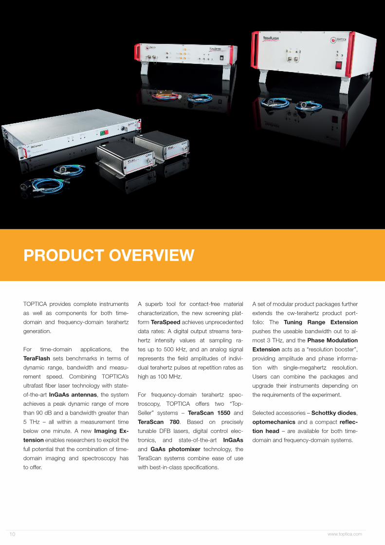
TOPTICA provides complete instruments
as well as components for both time-
domain and frequency-domain terahertz
generation.
For time-domain applications, the
TeraFlash sets benchmarks in terms of
dynamic range, bandwidth and measu-
rement speed. Combining TOPTICA’s
ultrafast fiber laser technology with state-
of-the-art InGaAs antennas, the system
achieves a peak dynamic range of more
than 90 dB and a bandwidth greater than
5 THz – all within a measurement time
below one minute. A new Imaging Ex-
tension enables researchers to exploit the
full potential that the combination of time-
domain imaging and spectroscopy has
to offer.
A superb tool for contact-free material
characterization, the new screening plat-
form TeraSpeed achieves unprecedented
data rates: A digital output streams tera-
hertz intensity values at sampling ra-
tes up to 500 kHz, and an analog signal
represents the field amplitudes of indivi-
dual terahertz pulses at repetition rates as
high as 100 MHz.
For frequency-domain terahertz spec-
troscopy, TOPTICA offers two “Top-
Seller” systems – TeraScan 1550 and
TeraScan 780. Based on precisely
tunable DFB lasers, digital control elec-
tronics, and state-of-the-art InGaAs
and GaAs photomixer technology, the
TeraScan systems combine ease of use
with best-in-class specifications.
A set of modular product packages further
extends the cw-terahertz product port-
folio: The Tuning Range Extension
pushes the useable bandwidth out to al-
most 3 THz, and the Phase Modulation
Extension acts as a “resolution booster”,
providing amplitude and phase informa-
tion with single-megahertz resolution.
Users can combine the packages and
upgrade their instruments depending on
the requirements of the experiment.
Selected accessories – Schottky diodes,
optomechanics and a compact reflec-
tion head – are available for both time-
domain and frequency-domain systems.

www.toptica.com 11
Time-Domain Instrumentation
TeraFlashTime-domain system, > 5 THz bandwidth,
90 dB peak dynamic range
Imaging ExtensionImaging in transmission and reflection,
up to 16 pixels/sec
TeraSpeedFast terahertz screening platform,
digital output up to 500 kS/s
Frequency-Domain Instrumentation
TeraScan 780/1550Frequency-domain platform,
< 10 MHz step size, 90 dB dynamic range
Tuning Range Extension3rd diode laser for TeraScan 1550,
bandwidth increase to 2.7 THz
Phase Modulation ExtensionFrequency resolution booster,
amplitude and phase data @ <10 MHz
Sources and Detectors
Photoconductive SwitchesInGaAs antennas with SM/PM fiber pigtail,
for time-domain terahertz applications
PhotomixersGaAs and InGaAs photomixers with fiber
pigtail, for frequency-domain terahertz
Schottky ReceiversTerahertz power detectors, for time-
domain and frequency-domain sources
Customized Systems and Accessories
Customized SystemsInnovative answers to “crazy” ideas
Transmission OptomechanicsMirror-based assemblies for transmission
measurements with and without focus
Reflection HeadCompact and robust design
for reflection measurements

www.toptica.com12
Versatile Time-Domain Terahertz PlatformTeraFlash
Real time data processing board
SM/PMFC/APC
SM/PMFC/APC
to emitter
to detector
free spacecollimatorsfibers
detector signal
bias voltage
Path length compensation
Voice coil + position sensor
SMA
Lemo
FemtoFErb 1560+ fiber delivery
Schematic diagram of the TeraFlash. Blue lines depict electric signals, red lines the optical signals.
0 1 2 3 4 5 60
20
40
60
80
100
Dyn
amic
Ran
ge (d
B)
Frequency (THz)TeraFlash spectrum. The peak dynamic range reaches 90 dB with 1000 averages – an industry record! With 10,000 averages, the peak dynamic range increases to 100 dB.
1 10 100 10000
20
40
60
80
100
Peak
Dyn
amic
Ran
ge (d
B)
Number of Averages
0.1 1 10Acquisition Time (s)
Peak dynamic range versus the number of averaged time traces (lower abscissa) and total acquisition time (upper abscissa).
The TeraFlash system combines
TOPTICA’s established femtosecond laser
technology and state-of-the-art InGaAs
photoconductive switches into a table-top
terahertz platform. Owing to a highly pre-
cise voice-coil delay stage with a timing
resolution of 1.3 fs, the TeraFlash achie-
ves a bandwidth greater than 5 THz and
a peak dynamic range of 90 dB - within
a measurement time below one minute!
The control software can flexibly adjust the
· Fiber-coupled InGaAs photoconductive switches
· More than 5 THz bandwidth, 90 dB peak dynamic range
· Variable terahertz path length between 15 cm and 110 cm
Key Features
scan time and the number of averages.
A carefully designed fiber delivery (patent
US 9,774,161) guides the laser pulses to
the terahertz antennas. Users can thus
arrange the antennas in transmission or
reflection, according to the requirements
of the experiment. They can even vary the
terahertz beam length between 15 cm and
110 cm, thanks to a unique time-of-flight
compensation stage.

www.toptica.com 13
Specifications TeraFlash
Components
Femtosecond laser, SM/PM fiber delivery (patent US 9,774,161), 2 delay stages (stationary / moving), 2 InGaAs photoconductive switches,
Electronics for data acquisition,
Laser FemtoFErb THz FD6.5
Laser wavelength 1560 nm
Laser pulse width < 60 fs (< 45 fs typ.)
Laser repetition rate 100 MHz
Terahertz emitter
InGaAs/InP photoconductive switch with 100 μm strip-line antenna #EK-000979: fiber length = 0.3 m#EK-000781: fiber length = 1.0 m #EK-000978: fiber length = 2.5 m
Terahertz receiver
InGaAs/InP photoconductive switch with 25 μm dipole antenna, 10 μm gap#EK-000981: fiber length = 0.3 m#EK-000782: fiber length = 1.0 m#EK-000980: fiber length = 2.5 m
Antenna packageCylindrical, ø 25 mm
Integrated Si lens and SM/PM fiber pigtail
Terahertz spectral range 0.1 - 5 THz (6 THz typ.)
Average terahertz power 30 µW typ.
Peak dynamic range > 90 dB (95 dB typ.)
Delay stage scan 20 - 200 ps
Frequency resolution< 5 GHz @ 200 ps scan< 50 GHz @ 20 ps scan
Acquisition ratePrecise scan: 60 s/spectrum, 70 ps delay, 5 THz bandwidth, peak dynamic range > 90 dBFast scan: 50 ms/spectrum, 50 ps delay, 3 THz bandwidth, peak dynamic range > 60 dB
Intermediate settings possible
Maximum measurement speed Max. 40 traces/sec (50 traces/sec upon request), 20 ps delay
Useable terahertz path length 15 .. 110 cm, adjustable via stationary delay
Computer interface Ethernet; USB-LAN network adapter included
Control software LabView-based GUI, included
Size (H x W x D) 180 mm x 450 mm x 560 mm
SpecificationsCLASS 1 LASER PRODUCTIE C 60825-1:2014
Further reading:N. Vieweg et al., Terahertz-time domain spectrometer with 90 dB peak dynamic range; J Infrared Milli. Terahz. Waves 35 (2014) 823-832.

www.toptica.com14
Fast and Flexible Imaging PlatformImaging Extension
An accessory to the TeraFlash, the Tera-
hertz Imaging Extension utilizes two
precise linear stages to scan a sample
through the focus of the terahertz beam.
The translational movement is synchro-
nized with the voice-coil delay of the
TeraFlash, resulting in a high measurement
speed of up to 16 pixels per second. The
Imaging Extension comes in two versions:
· Measurement speed: up to 16 pixels/sec
· Flexible configuration in transmission and reflection mode
· Data filtering in both time-domain and frequency-domain possible
Key Features
a “basic” setup for researchers who wish
to use their own optical components, and
a “complete” version that includes para-
bolic mirrors for beam shaping and focu-
sing. With the help of alignment pins, users
can quickly reconfigure the optics of the
complete version from a transmission
setup to a reflection geometry and vice
versa.
Images of a resolution test chart. Left: photograph, center: terahertz reflection image at full band-width, right: same image after spectral filtering (range 2.5 - 4.0 THz). The field of view is 5 x 5 cm and the smallest structures are less than 500 μm wide.
Complete version of the Terahertz Imaging Extension, configured in reflection (left) and
transmission (right).
Specifications Imaging Extension
Basic Version Complete Version
Linear stages 2 stages + motion controller included, positioning accuracy < 0.2 mm
Terahertz optics --4 mirrors included,
easy configuration in transmission and reflection
Mounts for terahertz antennas -- Included for TX and RX
Beam focus size -- Approx. 2.5 mm
Measurement speed Max. 16 pixel / sec @ 20 ps scan range
Positioning accuracy < 200 μm
Maximum field of view 15 cm x 15 cm
Sample weight Max. 2 kg
Angle of incidence (reflection) n.a. ± 8 deg.
Data acquisition Shaker movement and translation of linear stages are synchronized
Data filtering Possible, both in time-domain and frequency-domain
Contrast parametersAmplitude, phase, layer thickness, spectral amplitude in a pre-selected range,
amplitude and height profile as cross sections

www.toptica.com 15
SpecificationsSuperfast Terahertz Screening Platform
TeraSpeed
The TeraSpeed serves applications in
quality control and process monitoring
that require no spectral information, but
call for terahertz intensity measurements at
“extreme” speeds: The system is capable
of detecting individual terahertz pulses
at repetition rates as high as 100 MHz.
An integrated data-processing unit
converts the pulses to RMS values,
· Extremely fast measurements of terahertz pulse intensities
· Digital output: Data rates up to 500 kS/s, analog output up to 100 MHz
· Robust setup, no mechanically sensitive components
Key Features
enabling data streams at sampling rates
up to 500 kHz – orders of magnitude faster
than conventional terahertz systems.
Bringing together several cutting-edge
technologies, the TeraSpeed takes ad-
vantage of mature fiber laser technology,
powerful photoconductive emitters and
fast yet sensitive Schottky receivers.
-1.0 -0.5 0.0 0.5 1.0 1.50
2
4
6
8
Am
plitu
de (a
.u.)
Time (s)
Tissue paper Sponge
Wetting
Absorption dynamics of a sheet of tissue paper and a sponge, wetted with water.
Schematic of the TeraSpeed. Red: optical signals, blue: analog signals, black: digital signals.
Signal processing unit
SM/PMFC/APC
SM/PMFC/APC
to emitter
detector signal
emitter bias voltage
SMA
Lemo
PC
FemtoFErb 1560+ fiber delivery
aux. output
RF-to-RMSConverter
raw output
RMS output USBSMA
BNC
Acquisitiontrigger input
SMA
Binderdetector supply
SMAlaser clock
Further reading: F. Rettich et al., Field intensity detection of individual terahertz pulses at 80 MHz repetition rate; J Infrared Milli. Terahz. Waves 36:7 (2015) 607-612.S. Brinkmann et al., Towards Quality Control in Pharmaceutical Packaging: Screening Folded Boxes for Package Inserts; J Infrared Milli. Terahz. Waves 38:3 (2017) 339-346.
Specifications TeraSpeed
ComponentsFemtosecond laser, SM/PM fiber delivery (patent US 9,774,161),
TX: InGaAs photoconductive switch (#EK-000978)RX:High-bandwidth Schottky receiver (#EK-000961)
Antenna package See pages 16 and 24
Analog outputs“Raw signal out”: Direct signal of Schottky receiver, 100 MHz repetition rate
“RMS signal out”: Processed signals of RF-to-RMS converter, 100 kHz bandwidth
Dynamic range @ RMS signal output Typ. 40 dB
Digital output USB interface
Measurement modes of digital output“Snapshot”: Single-shot measurement, up to 100000 data points, sampling rate max. 500 kHz
“Continuous”: Continuous data streaming, sampling rate 1 kHz .. 500 kHz
Trigger input/outputInput trigger for acquisition start in “snapshot” mode
“Laser clock out”: Clock output of femtosecond laser, 100 MHz repetition rate
Control software Graphical user interface, included
Size (H x W x D) 90 mm x 450 mm x 500 mm; 110 mm x 450 mm x 545 mm with handles and feet
CLASS 1 LASER PRODUCTIE C 60825-1:2014

www.toptica.com16
InGaAs Antennas for Time-Domain Terahertz Generation & DetectionPhotoconductive Switches
Pulsed terahertz generation with lea-
ding-edge technology: Fiber-pigtailed
InGaAs antennas provide a bandwidth
up to 6 THz and an average power of
30 µW. The design, developed by Fraun-
hofer Heinrich-Hertz Institute (HHI, Berlin/
Germany), uses a multi-stack of InGaAs
absorber layers and InAlAs trapping lay-
ers to reduce the dark conductivity of the
Pulse trace of an InGaAs photoconductive switch.
· Compact modules with SM/PM fiber pigtail and silicon lens
· High terahertz power: > 30 µW average
· Large bandwidth: typ. 6 THz
Key Features
semiconductor and maximize the efficien-
cy of the device.
The emitter and detector modules feature
a strip-line and a dipole antenna, respecti-
vely, and are packaged with a Silicon lens
and SM/PM fiber. Customers can choose
between three different fiber lengths of
0.3 m, 1.0 m and 2.5 m.
0 10 20 30 40 50
-100
0
100
200
300
400
Elec
tric
�eld
am
plitu
de (a
.u.)
Scan time (ps)
Specifications Photoconductive Switches
Terahertz emitter
InGaAs/InP photoconductive switch with 100 μm strip-line antenna #EK-000979: fiber length = 0.3 m #EK-000781: fiber length = 1.0 m #EK-000978: fiber length = 2.5 m
Terahertz receiver
InGaAs/InP photoconductive switch with 25 μm dipole antenna, 10 μm gap #EK-000981: fiber length = 0.3 m #EK-000782: fiber length = 1.0 m #EK-000980: fiber length = 2.5 m
Semiconductor material Multi-layer structure of InGaAs and InAlAs on InP
Excitation wavelength 1.5 μm
Emitter / receiver bandwidth > 5 THz (6 THz typ.)
Average terahertz power Typ. 30 µW @ 20 mW laser power
Package Cylindrical, Ø 25 mm
Integrated Si lens and SM/PM fiber pigtail
Recommended operating conditionsAverage laser power 20 mW
Max. bias +100 V (unipolar, emitter), ± 3 V (receiver, only for testing)
Bias modulation Possible, up to 100 kHz
www.toptica.com 17
Next-Generation Femtosecond Fiber
Lasers
TOPTICA offers a large variety of ultra-
fast lasers, all of which come as ro-
bust, cost-effective systems with supe-
rior specifications. Owing to the use of
saturable-absorber mirror technology for
mode-locking, all lasers provide turnkey
operation and do not require any mecha-
nical alignment. The lasers do not need
any water-cooling either; simple air-cooling
ensures stable operation.
Lasers of the FemtoFiber pro series are
available both at the fundamental wave-
length of 1560 nm and frequency-
doubled to 780 nm. The short-pulse version
FemtoFiber pro IRS features an additional
non-linear fiber to generate pulses below
40 fs. Pulse durations and power levels of
the FemtoFiber pro series are thus well-
suited for terahertz generation in photo-
conductive switches or organic-crystal
emitters such as DAST, DSTMS or OH1.
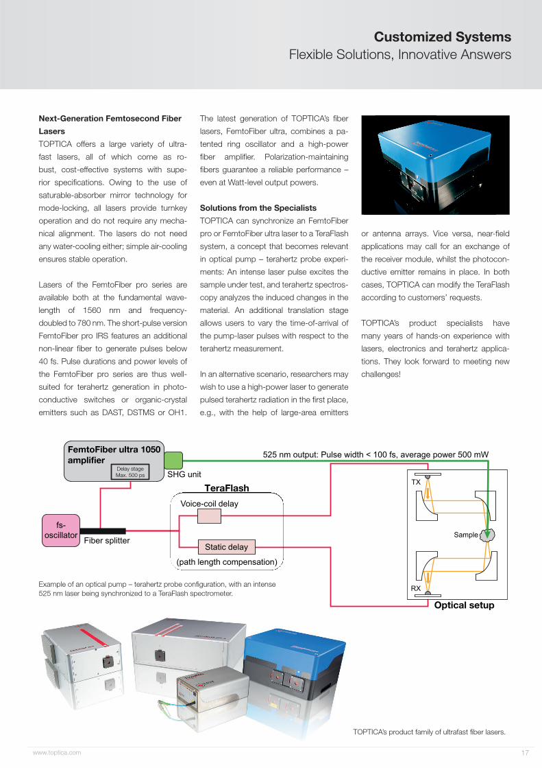
Flexible Solutions, Innovative AnswersCustomized Systems
TeraFlash
fs-oscillator
Voice-coil delay
Fiber splitter
(path length compensation)
Sample
RX
TX
Optical setup
SHG unit
525 nm output: Pulse width < 100 fs, average power 500 mW
Static delay
FemtoFiber ultra 1050amplifier
Delay stageMax. 500 ps
The latest generation of TOPTICA’s fiber
lasers, FemtoFiber ultra, combines a pa-
tented ring oscillator and a high-power
fiber amplifier. Polarization-maintaining
fibers guarantee a reliable performance –
even at Watt-level output powers.
Solutions from the Specialists
TOPTICA can synchronize an FemtoFiber
pro or FemtoFiber ultra laser to a TeraFlash
system, a concept that becomes relevant
in optical pump – terahertz probe experi-
ments: An intense laser pulse excites the
sample under test, and terahertz spectros-
copy analyzes the induced changes in the
material. An additional translation stage
allows users to vary the time-of-arrival of
the pump-laser pulses with respect to the
terahertz measurement.
In an alternative scenario, researchers may
wish to use a high-power laser to generate
pulsed terahertz radiation in the first place,
e.g., with the help of large-area emitters
or antenna arrays. Vice versa, near-field
applications may call for an exchange of
the receiver module, whilst the photocon-
ductive emitter remains in place. In both
cases, TOPTICA can modify the TeraFlash
according to customers’ requests.
TOPTICA’s product specialists have
many years of hands-on experience with
lasers, electronics and terahertz applica-
tions. They look forward to meeting new
challenges!
TOPTICA’s product family of ultrafast fiber lasers.
Example of an optical pump – terahertz probe configuration, with an intense 525 nm laser being synchronized to a TeraFlash spectrometer.

www.toptica.com18
TOPSellers for Frequency-Domain SpectroscopyTeraScan 780 / 1550
· Complete systems with high-end GaAs or InGaAs photomixers
· Highest bandwidth: TeraScan 780· Highest dynamic range: TeraScan 1550
Key Features
TOPTICA’s TeraScan platforms are “TOP-
Seller” configurations for frequency-
domain terahertz spectroscopy. The sys-
tems combine mature DFB diode lasers
with state-of-the-art GaAs or InGaAs pho-
tomixer technology. The TeraScan 780
offers an outstanding bandwidth, owing
to the wide tuning range of careful-
ly selected near-infrared DFB diodes.
The TeraScan 1550, in turn, sets new
benchmarks in terms of terahertz power
and dynamic range. Both systems feature
TOPTICA‘s proprietary “DLC smart” con-
trol electronics, and an intuitive software
interface.
The TeraScan systems lend themselves
both as versatile starter packages for
cw-terahertz research, and as base units
for system integrators.
Dynamic range of a TeraScan 1550 system.
0 0.2 0.4 0.6 0.8 1.0 1.2
Integration time 300 ms/step Integration time 3 ms/step
0
20
40
60
80
100
Dyn
amic
Ran
ge (d
B)
Frequency (THz)
Schematic of TeraScan systems.
RX
TX
AC Bias
DFB laser #2
DFB laser #1
Lock-inDetection
~
Dynamic range of a TeraScan 780 system. The dips are absorption lines of water vapor.
Integration time 300 ms/step Integration time 3 ms/step
0
20
40
60
80
Dyn
amic
rang
e (d
B)
0 0.5 1.0 1.5 2.0Frequency (THz)

www.toptica.com 19
Specifications TeraScan 780 / 1550
Lasers TeraScan 780 TeraScan 1550
Difference frequency tuning 1.8 THz (2.0 THz typ.) 1.2 THz (up to 2.7 THz with Tuning Range Extension)
Tuning speed Up to 0.1 THz / sec
Frequency accuracy < 2 GHz
Minimum frequency step size < 10 MHz
Terahertz emitter #EK-000831, GaAs photomixer #EK-000724, high-bandwidth InGaAs photodiode
Terahertz receiver #EK-000832, GaAs photomixer #EK-000725, InGaAs photomixer
Antenna type Log-spiral Bow-tie
Terahertz polarization Circular Linear
Emitter and receiver packageCylindrical, ø 1”
Integrated Si lens and SM/PM fiber pigtailCylindrical, ø 25 mm
Integrated Si lens and SM/PM fiber pigtail
Terahertz power (typ.)2 µW @ 100 GHz, 0.3 µW @ 500 GHz
100 µW @ 100 GHz, 10 µW @ 500 GHz
Terahertz dynamic range (300 ms integration time)
80 dB @ 100 GHz70 dB @ 500 GHz
90 dB @ 100 GHz70 dB @ 500 GHz
Laser size (H x W x D) and weightTwo DFB pro L laser heads, each with dimensions
90 mm x 90 mm x 244 mm (H x W x D), weight 2.8 kg
Two DFB pro BFY laser heads, each with dimensions 60 mm x 120 mm x 165 mm (H x W x D),
weight 1 kg
Control unit DLC smart
Controller size (H x W x D) and weight 50 mm x 480 mm x 290 mm, 4 kg
Computer interface Ethernet
Software Control software with GUI + Remote command interface
Key advantages High bandwidth with one set of lasers High terahertz power, compact laser units
CLASS 1 LASER PRODUCTIE C 60825-1:2014
VISIBLE / INVISIBLE LASER RADIATIONAVOID DIRECT EXPOSURE TO BEAM
CLASS 3B LASER PRODUCTCLASS 4 LASER PRODUCT
(DIN EN 60825-1:2014)
Specifications
Absorption spectrum of the plastic explosive RDX, recorded with the TeraScan 780.
0.2 0.4 0.6 0.8 1.0 1.21E-4
1E-3
0.01
0.1
1
Tran
smitt
ance
Frequency (THz)
Further reading:A. Roggenbuck et al., Coherent broadband continuous-wave terahertz spectroscopy on solid-state samples; New J. Phys. 12 (2010) 43017-43029.A.J. Deninger et al., 2.75 THz tuning with a triple-DFB laser system at 1550 nm and InGaAs photomixers; J Infrared Milli. Terahz. Waves 36 (2015) 269-277.

www.toptica.com20
DFB Lasers for cw Terahertz GenerationTeraBeam 780 / 1550
Each TeraBeam system comprises two
distributed feedback (DFB) lasers with
built-in optical isolators and fiber-optic
beam combination. Available at 780 nm
and 1.5 μm, the TeraBeam matches
the excitation wavelengths of GaAs and
InGaAs terahertz emitters, respectively.
TOPTICA carefully selects the laser
diodes, paying close attention to their
mode-hop-free tuning range, and records
precise tuning curves (wavelength vs.
temperature), which are stored in a
lookup table. The DLC smart addresses
the thermoelectric coolers of both DFB
diodes in order to tune to a desired
terahertz frequency. The minimum
step size is on the 1 MHz level, which
corresponds to a temperature change of
only 40 μK per laser.
· Two DFB lasers with micro-
processor-based frequency control
· Available wavelengths:
780 nm and 1.5 μm
· Frequency accuracy < 2 GHz,
minimum step size < 10 MHz
Key Features
Specifications TeraBeam 780 / 1550
Lasers TeraBeam 780 TeraBeam 1550
Laser wavelengths 783 nm + 785 nm 1533 nm + 1538 nm
Laser power > 40 mW per two-color fiber output 25 - 30 mW per two-color fiber output
Difference frequency tuning0 - 1.8 THz
(2.0 THz typ.)0 - 1.2 THz
(up to 2.7 THz with Tuning Range Extension)
Tuning speed Up to 0.1 THz / sec
Frequency accuracy < 2 GHz
Minimum frequency step size < 10 MHz
Frequency stability per laser* Typ. 20 MHz RMS, 100 MHz p-p @ 5 hrs
Laser size (H x W x D) and weightTwo DFB pro L laser heads, each with dimensions
90 mm x 90 mm x 244 mm (H x W x D), weight 2.8 kg
Two DFB pro BFY laser heads, each with dimensions 60 mm x 120 mm x 165 mm (H x W x D),
weight 1 kg
Control unit DLC smart
Controller size (H x W x D) and weight 50 mm x 480 mm x 290 mm, 4 kg
Laser diode warranty 5000 hrs or 2 years (whatever comes first)
*At constant environmental conditions
DFB laser #2
DFB laser #1
∆ν = 0 GHz
∆ν = 2.28 THzLaser #2
Laser #1
0 10 20 30 40 50782
784
786
Wav
elen
gth
(nm
)
Temperature (°C)
Frequency calibration of a TeraBeam 780 system. The wavelengths of the two DFB la-sers overlap at approx. 784.6 nm (shaded bar). By heating laser #1 and cooling laser #2, the difference frequency increases up to 2.3 THz.Schematic of TeraBeam.
Further reading:D. Stanze et al., Compact cw terahertz spectrometer pumped at 1.5 μm wavelength; J Infrared Milli. Terahz. Waves 32 (2011) 225-232.
CLASS 1 LASER PRODUCTIE C 60825-1:2014
VISIBLE / INVISIBLE LASER RADIATIONAVOID DIRECT EXPOSURE TO BEAM
CLASS 3B LASER PRODUCTCLASS 4 LASER PRODUCT
(DIN EN 60825-1:2014)

www.toptica.com 21
Owing to the efficiency of the latest InGaAs
photomixers, TOPTICA has been able to
push the frequency limits of frequency-
domain spectrometers. Whilst one DFB
laser at 1.5 μm offers a continuous tuning
range of approximately 600 GHz, a com-
bination of three lasers covers the entire
frequency range from DC to 2.0 THz, or
– using a more elaborate set of combina-
tions – even up to 2.7 THz.
TOPTICA’s Tuning Range Extension thus
provides access to a frequency range
that used to be beyond reach with com-
mercial frequency-domain spectrometers.
The frequency accuracy achieved with
TOPTICA’s DLC smart controller is so
high that spectra obtained with different
subsets of lasers can easily be “stitched
together”.
Specifications Tuning Range Extension
THz Tuning Extension 2.0 THz Tuning Extension 2.7
Base system TeraBeam 1550 (λ1 = 1533 nm, λ1 = 1538 nm)
3rd laser λ3 = 1550 nm
Difference frequency tuning
0 - 2.0 THz· 0 - 1.2 THz with lasers #1 and #2 (TeraBeam)· 0.9 - 2.0 THz with lasers #2 and #3
0 - 2.7 THz· 0 - 1.2 THz with lasers #1 and #2 (TeraBeam)· 0.9 - 2.0 THz with lasers #2 and #3· 1.5 - 2.7 THz with lasers #1 and #3
Laser power See TeraBeam 1550
Tuning speed See TeraBeam 1550
Frequency accuracy See TeraBeam 1550
Laser size (H x W x D) and weight 60 mm x 120 mm x 165 mm, 1 kg
Controller size (H x W x D) and weight 50 mm x 480 mm x 290 mm, 4 kg
Laser diode warranty 5000 hrs or 2 years (whatever comes first)
Triple-Laser Systems – Frequencies up to 2.7 THzTuning Range Extension
Further reading:A.J. Deninger et al., 2.75 THz tuning with a triple-DFB laser system at 1550 nm and InGaAs photomixers; J Infrared Milli. Terahz. Waves 36 (2015) 269-277.
DFB laser #3 Tuning Range Extension
RX
TX
AC Bias
DFB laser #2
DFB laser #1
Lock-inDetection
~
193.0 193.5 194.0 194.5 195.0 195.5 196.0
Frequency (THz)
Wavelength (nm)
1550 1545 1540 1535 1530
#3
#2#1
#1
#2
#3
#1 and #2: 0 - 1.2 THz
#1 and #3: 1.5 - 2.7 THz
#2 and #3: 0.9 - 2.1 THz
#1 and #2: 0 - 1.2 THz
#2 and #3: 0.9 - 2.1 THz
Schematic of TeraScan (red) with Tuning Range Extension (purple).
Combinations of lasers used for the Tuning Range Extension to 2.0 THz (top) and 2.7 THz (bottom).
CLASS 1 LASER PRODUCTIE C 60825-1:2014

www.toptica.com22
Resolution Booster for TeraScan SystemsPhase Modulation Extension
The Phase Modulation Extension acts as
a “resolution booster“ for cw-terahertz
measurements. Powerful piezo actuators
stretch the length of two single-mode
fibers (~ 60 m each) - one in the transmitter
path, one in the receiver path. This results
in a fast and accurate modulation of the
THz phase. Users can then retrieve both
amplitude and phase information with a
spectral resolution on the single-MHz level.
The Phase Modulation Extension is avail-
able at 780 nm and 1.5 μm, perfectly
fitting the respective TeraScan systems.
The twin-fiber concept not only doubles
the modulation amplitude, but also increa-
ses the thermal stability of the setup.
· Fast and accurate modulation of the
terahertz phase
· Twin fiber stretcher with
piezo actuators and HV driver
· Path length modulation up to
3 mm @ 1 kHz
Key Features
TX
AC Bias
DFB laser #2
Lock-inDetection
DFB laser #1
TeraScan
Phase Modulation Extension
RX
Phase "fringes"
Fiber-stretcher spectrum
0
1.150 1.155 1.160 1.165 1.170 1.175
-20
-10
10
20
THz
Pho
tocu
rren
t (nA
)
Frequency (THz)
Terahertz photocurrent of a frequency scan across a water-vapor resonance. The black trace depicts the phase “fringes” as measured with a standard TeraScan 1550 system. The yellow trace shows the envelope spectrum obtained with the Phase Modulation Extension; the high frequency resolution unveils small-scale standing-wave effects in the optical path.
Schematic of TeraScan (red) with Phase Modu-lation Extension (black).
Further reading: A. Roggenbuck et al., Using a fiber stretcher as a fast phase modulator in a continuous wave terahertz spectrometer; JOSA B 29 (2012) 614-620.
Specifications Phase Modulation Extension
Phase Modulation Extension NIR Phase Modulation Extension IR
Concept Twin fiber stretcher with piezo actuators
Wavelength780 nm, as defined by
TeraScan 780 / TeraBeam 7801.5 µm, as defined by
TeraScan 1550 / TeraBeam 1550
Difference frequency tuning See TeraScan / TeraBeam systems
Difference frequency resolutionSee TeraScan / TeraBeam systems.
Complete amplitude + phase information available at maximum resolution.
Fibers 2 x 60 m, SM/PM fibers
Max. path length modulation 3 mm @ 1 kHz
HV amplifier Included
Software Included, part of control program

www.toptica.com 23
· Cutting-edge GaAs (780 nm) and
InGaAs (1.5 μm) photomixers
· Fully-packaged modules with silicon
lens and SM/PM fiber pigtail
· Up to 100 µW output power
Key Features
Specifications Photomixers
GaAs Modules InGaAs Modules
Terahertz emitter #EK-00831, GaAs photomixer #EK-000724, InGaAs photodiode
Terahertz receiver #EK-000832, GaAs photomixer #EK-000725, InGaAs photomixer
Excitation wavelength 0.8 μm 1.5 μm
Antenna type Log-spiral Bow-tie
Terahertz polarization Circular Linear
Emitter and receiver packageCylindrical, ø 1”
Integrated Si lens and SM/PM fiber pigtailCylindrical, ø 25 mm
Integrated Si lens and SM/PM fiber pigtail
Emitter and receiver bandwidth Approx. 3 THz
Terahertz power (typ.)2 µW @ 100 GHz
0.3 µW @ 500 GHz100 µW @ 100 GHz10 µW @ 500 GHz
Terahertz dynamic range(300 ms integration time)
80 dB @ 100 GHz70 dB @ 500 GHz
90 dB @ 100 GHz70 dB @ 500 GHz
Having teamed up with some of the
world’s leading terahertz research
institutes, TOPTICA is able to offer top-
quality GaAs and InGaAs photomixers.
Both material systems have their own
merits. Systems with GaAs photomixers
provide high bandwidths, owing to the
wide continuous tuning range of 780 nm
lasers. InGaAs emitters, on the other hand,
generate power at record levels and take
advantage of mature yet inexpensive
1.5 μm telecom technology.
All of TOPTICA’s photomixer modules
come equipped with a Silicon lens, an
electric connector and SM/PM fiber pigtail.
The all-fiber design eliminates the need for
time-consuming laser beam alignment,
and enables an easy and flexible integra-
tion into any terahertz assembly.
Top-Quality Modules for Frequency-Domain Terahertz Generation and DetectionPhotomixers
Top view and cross section (right) of a planar photomixer with interdigitated finger structure. Cross-section of a p-i-n photodiode. V+ and V- denote the applied bias voltage.
0.01
0.1
1
10
100
Pow
er (µ
W)
0 0.5 1.0 1.5 2.0Frequency (THz)
Output power spectrum of an InGaAs photodiode emitter.
V-
Semi-insulating substrate
Optical beat
Metallization
Active layer Semi-insulating substrate
V+ V+V V
V-
Semi-insulating substrate
Optical beat
Metallization
Active layer Semi-insulating substrate
V+ V+V V
V-
Semi-insulating substrate
Optical beat
Metallization
Active layer Semi-insulating substrate
V+ V+V V

www.toptica.com24
Schottky ReceiversAccessories
Schottky diodes work as incoherent
receivers (i.e., power detectors) for both
pulsed and cw-terahertz radiation. In
contrast to photomixer receivers or photo-
conductive switches, they are insensitive
to the terahertz phase, but accomplish
a direct measurement of the field inten-
sity of the incident terahertz wave. This
brings significant advantages for terahertz
imaging, which benefits from both speed
and sensitivity of the Schottky receivers.
A special high-bandwidth version lends
itself for terahertz communication, or for
the study of ultrafast processes – owing
to its capability of resolving the ampli-
tudes of individual terahertz pulses, even
at typical repetition rates of femtosecond
fiber lasers.
· Output signal proportional to
incident terahertz power
· Ideally suited for terahertz imaging
· High-bandwidth version measures
individual terahertz pulses
Key Features
0 0.5 1.0 1.5
0.01
0.1
1
10
100
Phot
ocur
rent
(nA)
Frequency (THz)
Cw-terahertz spectrum of air with water vapor lines, recorded with a GaAs photomixer-emitter and a Schottky receiver.
-20
0
20
40
60
Ampl
itude
(mV)
-20 -10 0 10 20Time (ns)
Terahertz pulse train at 100 MHz repetition rate, detected with a high-bandwidth Schottky receiver.
Specifications Accessories - Schottky Receivers
#EK-000933 (“High Responsivity“) #EK-000961 (“High Bandwidth“)
Concept Zero-bias Schottky diode
Antenna type Log-spiral
Terahertz bandwidth 50 - 1500 GHz
Noise-equivalent power7 pW/sqrt(Hz) @ 100 GHz100 pW/sqrt(Hz) @ 1 THz
70 pW/sqrt(Hz) @ 100 GHz 1000 pW/sqrt(Hz) @ 1 THz
Responsivity22000 V/W @ 100 GHz,
1100 V/W @ 1 THz230 V/W @ 100 GHz,
17 V/W @ 1 THz
Amplifier bandwidth 10 Hz - 1 MHz 10 MHz - 4 GHz
Power supply Included
Warranty 1 year
Further reading: F. Rettich et al., Field intensity detection of individual terahertz pulses at 80 MHz repetition rate; J Infrared Milli. Terahz. Waves 36 (2015) 607-612. M. Yahyapour et al., A flexible, phase-insensitive system for broadband cw-terahertz spectroscopy and imaging; IEEE Transact. Terahertz Science Technol. 6 (2016) 670-673.

www.toptica.com 25
· Compact and robust setups for trans-
mission and reflection measurements
· Flexible solutions with and without
beam focus
· Parabolic mirrors preserve full system
bandwidth
Key Features
TOPTICA offers four different sets of
optomechanics, designed for the most
common beam-path configurations. All
of the assemblies make use of parabolic
mirrors in order to collimate, guide and
focus the terahertz beam. Unlike plastic
lenses, mirrors do not exhibit any
transmission losses and therefore
preserve the full bandwidth of TOPTICA’s
TeraFlash and TeraScan systems.
For transmission-mode experiments, three
rail-based assemblies produce a colli-
mated terahertz beam (2-mirror setups),
or an additional focus (4-mirror setup).
For applications that require a reflection
geometry, a compact, handheld module
generates a focus at the location of the
sample.
#BG-002653
#BG-001784
#BG-001481
#OE-000888
OptomechanicsAccessories
Specifications Accessories - Optomechanics
#BG-002653(Compact 2-mirror setup)
#BG-001481(2-mirror setup)
#BG-001784(4-mirror setup)
#OE-000888(Reflection head)
User mode Transmission Transmission Transmission Reflection
No. of parabolic mirrors 2 2 4 4
Collimating mirrors Ø 1", focal length 2" Ø 2", focal length 3" Ø 2", focal length 3" Ø 1", focal length 2"
Focussing mirrors -- -- Ø 2", focal length 2" Ø 1", focal length 4"
Focus size -- -- Approx. 2 mm Approx. 2.5 mm
2 xyz stages for photomixers -- Included Included --
Manual delay stage -- Included Included --
Motorized delay stage No, please see Phase Modulation Extension
Optical rails Included Included Included --
Compatibility TeraFlash, TeraScan 1550TeraFlash, TeraScan 1550, TeraScan 780, TeraSpeed
TeraFlash, TeraScan 1550, TeraScan 780, TeraSpeed
TeraFlash, TeraScan 1550

www.toptica.com26
Time-Domain vs. Frequency-Domain
Highest Resolution:
Frequency-Domain Systems
Frequency-domain spectroscopy is
the preferred choice for applications
requiring highest spectral resolution.
While a pulsed terahertz spectro-
meter offers a resolution on the 10 GHz
level, cw systems allow frequency
steps with single-megahertz precision.
Trace gas sensing, specifically at low pres-
sure, benefits from the precise frequency
control of TOPTICA’s TeraScan platforms.
In terms of system complexity, frequency-
domain systems do not require a delay
stage, therefore the price is lower than
that of their time-domain counterparts.
Highest Bandwidth:
Time-Domain Systems
Time-domain spectroscopy offers the
advantage of a very broad bandwidth;
spectra acquired with photoconductive
switches extend beyond 5 THz. Measure-
ment speed provides the second advan-
tage. The TeraFlash acquires a single
spectrum in less than 50 ms, and the
collection of 1000 averages, an efficient
method to reduce the noise level, is com-
pleted in less than a minute. Time-domain
systems also lend themselves to thickness
gauging via time-of-flight measurements:
The broad spectrum translates into micro-
meter-level thickness resolution.
Highest Speed:
Terahertz Screening Systems
Numerous applications in industrial
process control require neither spectral
data nor thickness information, but call
for intensity measurements at maximum
speed. The novel concept of the TeraSpeed
– the combination of a powerful photo-
conductive switch and a sensitive Schottky
receiver – necessitates neither any delay
stage, nor pulse-picking or lock-in detec-
tion. The result is not only a very robust
system, but one that outperforms conven-
tional time-domain terahertz instruments in
terms of speed by four to seven orders of
magnitude.
0 1 2 3 4 5 6 70
20
40
60
80
100
Dyn
amic
Ran
ge (d
B)
Frequency (THz)
TD-Terahertz: More than 6 THz bandwidth.
0 0.5 1.0 1.5 2.00
20
40
60
80
100
Dyn
amic
Ran
ge (d
B)
Frequency (THz)
FD-Terahertz: Single-megahertz resolution.
Specifications Time-Domain vs. Frequency-Domain
TeraScan TeraFlash TeraSpeed
Bandwidth 0.05 - 2.7 THz 0.1 - 5 (6) THz N.A.
Peak dynamic range 90 (100) dB 90 (95) dB 40 dB
Frequency resolution < 10 MHz 10 GHz typ. N.A.
Spectral selectivity Yes No No
Acquisition time (spectrum)30 s .. 3 hrs (complete spectrum,
depending on resolution and lock-in time)25 ms .. 1 min
(depending on number of averages)Analog: 10 nsDigital: 2 μs
Applications
Plastic inspection + ++ +
Paint and coating layers 0 ++ -
Industrial quality control + + ++
Non-destructive testing + ++ ++
Material research ++ ++ ++
Gas sensing ++ 0 -
Hydration monitoring + + ++
Ultrafast dynamics - 0 ++
Communication ++ - -
Metamaterials and micro-optics ++ + -
Fundamental physics ++ ++ +
Suitability: ++ Excellent + Good 0 Limited - Not suitable
-20
0
20
40
60
Ampl
itude
(mV)
-20 -10 0 10 20Time (ns)
Terahertz screening: 100 MHz pulse train.
-200 0 1 -100.5 2Time (ns)Frequency (THz) Frequency (THz)
01.0 3 101.5 4 202.0 7
60100100
408080
206060
04040
-202020
00
Am
plitu
de (m
V)
Dyn
amic
Ran
ge (d
B)
Dyn
amic
Ran
ge (d
B)
65

www.toptica.com 27
Order Information
Product Name Order Information Page
TeraFlash Time-domain terahertz spectroscopy platform 12
THz Imag. / Basic * Imaging extension, basic version without terahertz optics 14
THz Imag. / Complete * Imaging extension, complete version including terahertz optics 14
TeraSpeed Terahertz screening system 15
#EK-000979 InGaAs photoconductive switch for terahertz generation, fiber length 0.3 m 16
#EK-000781 InGaAs photoconductive switch for terahertz generation, fiber length 1.0 m 16
#EK-000978 InGaAs photoconductive switch for terahertz generation, fiber length 2.5 m 16
#EK-000981 InGaAs photoconductive switch for terahertz detection, fiber length 0.3 m 16
#EK-000782 InGaAs photoconductive switch for terahertz detection, fiber length 1.0 m 16
#EK-000980 InGaAs photoconductive switch for terahertz detection, fiber length 2.5 m 16
TeraScan 780 Frequency-domain terahertz platform based on 780 nm lasers and GaAs photomixers 18
TeraScan 1550 Frequency-domain terahertz platform based on 1.5 μm lasers and InGaAs photomixers 18
TeraBeam 780 Two-color DFB laser at 780 nm, without terahertz antennas 20
TeraBeam 1550 Two-color DFB laser at 1.5 μm, without terahertz antennas 20
THz Tuning Ext. 2.0 ** 3rd laser head for TeraScan 1550, tuning range extension to 2.0 THz 21
THz Tuning Ext. 2.7 ** 3rd laser head for TeraScan 1550, tuning range extension to 2.7 THz 21
THz Phase Mod / NIR *** Twin fiber stretcher for terahertz phase modulation, for 780 nm lasers 22
THz Phase Mod / IR ** Twin fiber stretcher for terahertz phase modulation, for 1.5 µm lasers 22
#EK-000831 GaAs photomixer for cw-terahertz generation 23
#EK-000832 GaAs photomixer for cw-terahertz detection 23
#EK-000724 InGaAs photodiode for cw-terahertz generation 23
#EK-000725 InGaAs photomixer for cw-terahertz detection 23
#EK-000933 Schottky receiver, high-responsivity version 24
#EK-000961 Schottky receiver, high-bandwidth version 24
#BG-002653 Compact optics assembly (transmission, collimated beam) 25
#BG-001481 Flexible optics assembly (transmission, collimated beam) 25
#BG-001784 Flexible optics assembly (transmission, collimated + focused beam) 25
#OE-000888 Reflection head 25
*
**
***
Requires TeraFlash
Requires TeraScan 1550 or TeraBeam 1550
Requires TeraScan 780 or TeraBeam 780

www.toptica.com28
TOPTICA Worldwide
TOPTICA Photonics, Inc.5847 County Road 41Farmington, NY 14425U.S.A.Phone: +1 585 657 6663Fax: +1 877 277 [email protected]
TOPTICA Photonics, K.K.2-9-5, Miyanishi-cho, Fuchu-shi, Tokyo, 183-0022, JapanPhone: +81 42 306 9906Fax: +81 42 306 [email protected]
TOPTICA Photonics AGLochhamer Schlag 19D-82166 Graefelfing / MunichGermanyPhone: +49 89 85837-0Fax: +49 89 [email protected]
BR
-Ter
aher
tz T
echn
olog
ies-
2018
-03
SpainDelta OpticsEdificio CTM O-210Crta Villaverde-Vallecas, Km 3,500 28053 Madrid, Spain Phone: +34 911 130 824Fax: +34 910 113 [email protected]
Australia & New ZealandLastek Pty. Ltd.Thebarton Campus10 Reid Street5031 Thebarton, SA, Australia Phone: +61 8 8443 8668Fax: +61 8 8443 [email protected]
JapanTOPTICA PHOTONICS, K.K.2-9-5, Miyanishi-cho, Fuchu-shi, Tokyo, 183-0022, Japan Phone: +81 42 306 9906Fax: +81 42 306 9907 [email protected]
TaiwanLuxton Inc.F4, No. 2, Technology Road V,Hsinchu Science Park,Hsinchu 30078, TaiwanPhone: +886 3 666 2097Fax: +886 3 666 [email protected]
IsraelLahat Technologies Ltd. 17 Atir Yeda St.Kfar Saba 4464313, Israel Phone: +972 9 76 46 200Fax: +972 9 76 46 204 [email protected]
IndiaSimco Global Technology & Systems Ltd.Simco House (Head Office)14 Bhawani KunjBehind Sector D-II Vasant Kunj110070 New Delhi, IndiaPhone: +91 11 2689 9867Fax: +91 11 2612 [email protected]
RussiaEuroLase Ltd.Profsoyuznaya 93-AOffice 404 117997 Moscow, RussiaPhone: +7 495 3363044Fax: +7 495 [email protected]
FranceOpton Laser InternationalParc Club Orsay Université29, rue Jean RostandF-91893 Orsay Cedex, FrancePhone: +33 1 6941 0405Fax: +33 1 6941 [email protected]
United Kingdom & IrelandTOPTICA Photonics UK Unit SU4B, Lansbury Estate 102 Lower Guildford RoadKnaphill, WokingSurrey, GU21 2EP, Great BritainPhone: +44 1483 799 030 Fax: +44 1483 799 [email protected] www.toptica.com
USA, Canada & MexicoTOPTICA Photonics, Inc.5847 County Road 41Farmington, NY 14425, U.S.A.Phone: +1 585 657 6663Fax: +1 877 277 [email protected]
Singapore, Malaysia & ThailandPrecision Technologies Pte Ltd211 Henderson Road # 13-02Henderson Industrial ParkSingapore 159552Phone: +65 6273 4573Fax: +65 6273 [email protected]
Every other country not listedTOPTICA Photonics AGLochhamer Schlag 19D-82166 Graefelfing / Munich, GermanyPhone: +49 89 85837 0Fax: +49 89 85837 [email protected]
KoreaJINSUNG LASER7F, E-Dong, Leaders Town#310, ManNyeon-Dong, Seo-GuDaejeon, 302-834, South KoreaPhone: +82 42 823 5300Fax: +82 42 823 [email protected]
ChinaUniversal Technology Co. Ltd.Room B810, Capital Group PlazaNo. 6 Chaoyangmen Bei Da StreetDongcheng DistrictBeijing 100027, P.R. China Phone: +86 10 8528 3377-607Fax: +86-10 8528 [email protected]