Embed Size (px)
Citation preview
TeraHertz Kerr effect in GaP crystal
J. Degert, M. Geye, E. Abraham, E. Freysz
Laboratoire Ondes et Matière d’Aquitaine
University of Bordeaux
France
Dept. Physics, Bangalore, October 24 2011
Outline
1. Introduction:
2. THz spectroscopy application to the GaP crystal
3. THz- Kerr effect in GaP
4. Conclusions and prospects

Conventional Kerr effect experiment
Set-up
To lock-in amplifier
• The pump induces a nonlinear third-order polarization in an isotropic medium • The medium becomes birefringent
• The birefringence induced in medium placed in between two crossed polarisers is sensed by a probe-beam whose polarization is at 45° with respect to the pump beam .
• Pump and probe pulses can be delayed to perform time-resolved experiment
Photodiode
probe pulse
Pump pulse
Liquid or Crystal
/2l
Polariser/4l
Crossed Polariser
Dt
Conventional Kerr effect experiment
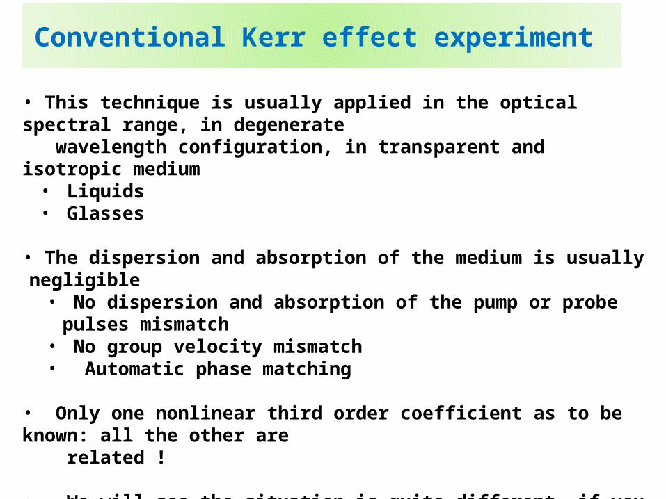
• This technique is usually applied in the optical spectral range, in degenerate wavelength configuration, in transparent and isotropic medium
• Liquids• Glasses
• The dispersion and absorption of the medium is usually negligible• No dispersion and absorption of the pump or probe pulses mismatch• No group velocity mismatch• Automatic phase matching
• Only one nonlinear third order coefficient as to be known: all the other are related !
• We will see the situation is quite different, if you perform a THz Kerr effect experiment in a cubic crystal (GaP) using a visible pulse as a probe
The first THz Kerr effect experiment
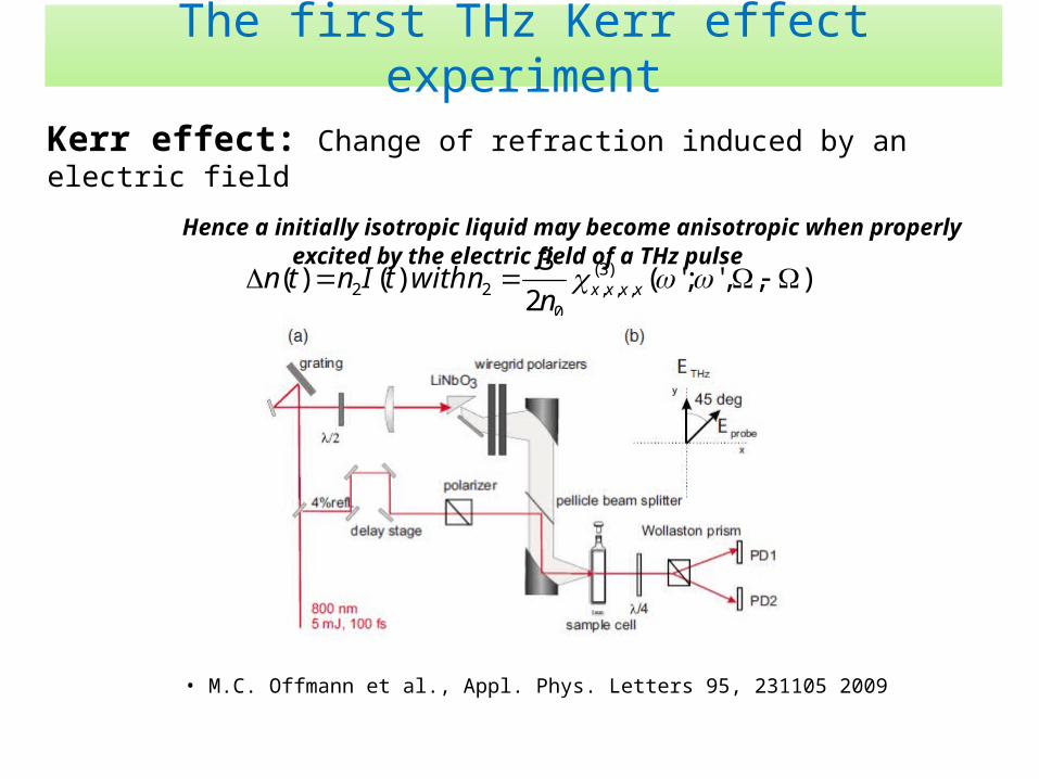
Kerr effect: Change of refraction induced by an electric field
Hence a initially isotropic liquid may become anisotropic when properly excited by the electric field of a THz pulse
),,';'(2
3 )()( )3(
,,,0
22 xxxxnnwithtIntn
• M.C. Offmann et al., Appl. Phys. Letters 95, 231105 2009
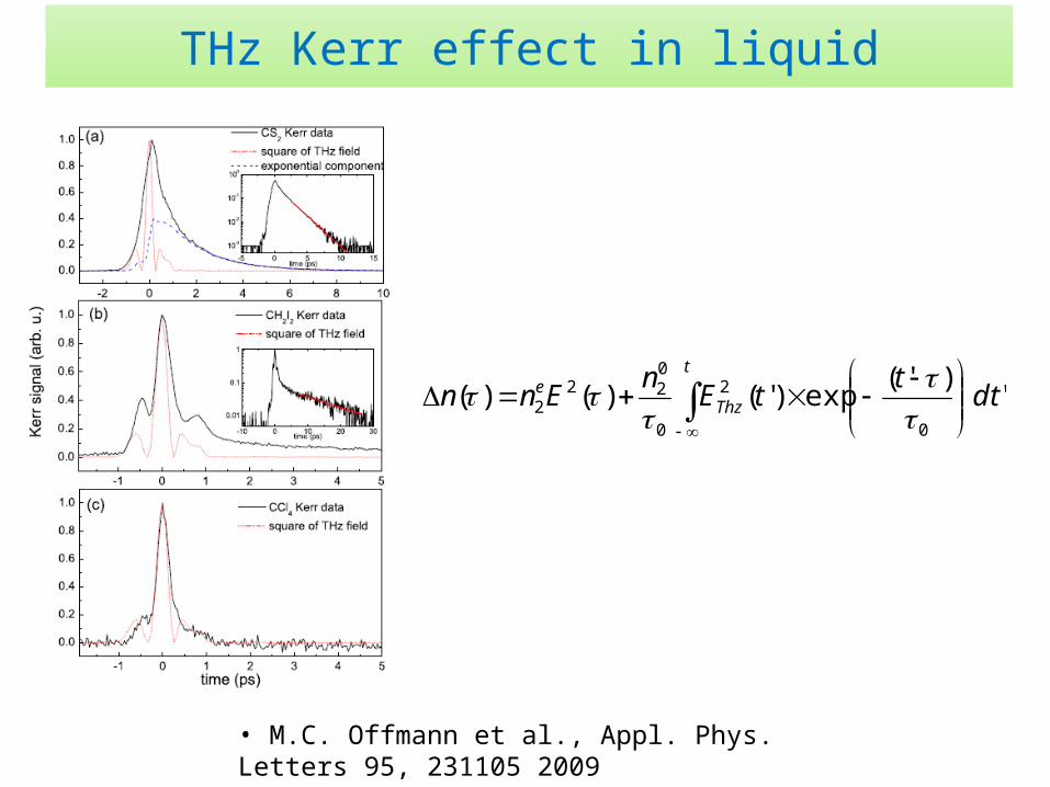
THz Kerr effect in liquid
' )'(
exp)'()()(0
2
0
022
2 dtt
tEn
Ennt
Thze
• M.C. Offmann et al., Appl. Phys. Letters 95, 231105 2009
THz spectroscopy of GaP
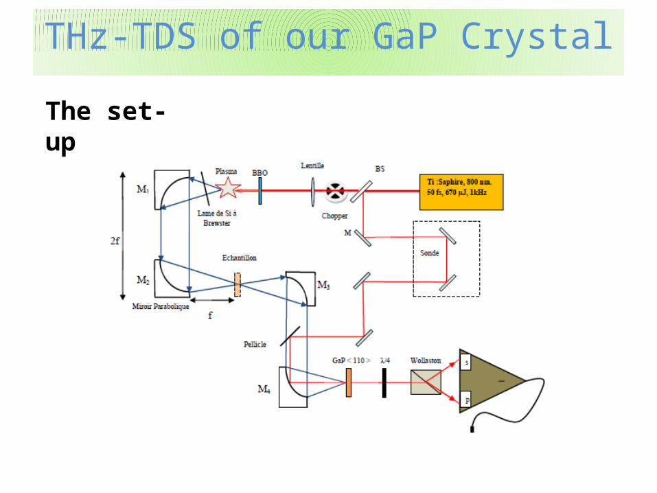
THz-TDS of our GaP CrystalTHz-TDS of our GaP Crystal
The set-up
THz-TDS of our GaP CrystalTHz-TDS of our GaP Crystal
0 1 2 3 4 5 6 7
3.3
3.4
3.5
3.6
Ref
ract
ive
ind
ex
Frequency (THz)
0 1 2 3 4 5 6 70
10
20
30
40
Ab
sorp
tio
n c
oef
fici
ent
(cm
-1)
Frequency (THz)
0 1 2 3 4 5 6 7 8 9 10
1E-11
1E-10
1E-9
EO
sig
nal
(A
)
Frequency (THz)
ref GaP
0 5 10 15
-10
0
10
20
30
EO
sig
nal
(n
A)
time (ps)
ref GaP
FT
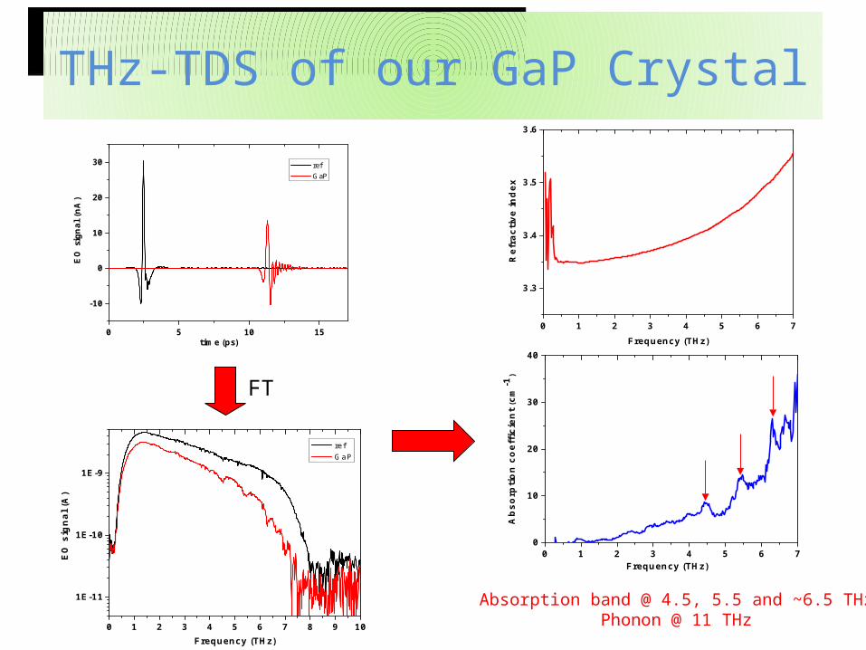
Absorption band @ 4.5, 5.5 and ~6.5 THzPhonon @ 11 THz
THz-TDS of our GaP CrystalTHz-TDS of our GaP Crystal
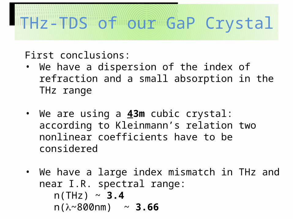
First conclusions:• We have a dispersion of the index of refraction and a small
absorption in the THz range
• We are using a 43m cubic crystal: according to Kleinmann’s relation two nonlinear coefficients have to be considered
• We have a large index mismatch in THz and near I.R. spectral range:
n(THz) ~ 3.4n(l~800nm) ~ 3.66
THz Kerr effect in GaP
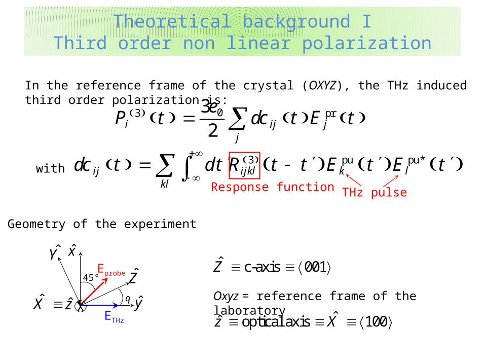
03 pr32i ij j
j
P t t E te
dc In the reference frame of the crystal (OXYZ), the THz induced third order polarization is:
3 pu pu*ij ijkl k l
kl
t d R t E Edc t t t t
with
Response function
Eprobe
ETHz
X
45°
x
yˆ ˆX z
Z
Y
q
Geometry of the experiment
c-axis 001Z
THz pulse
Oxyz = reference frame of the laboratory
optical axis 100ˆz X
Theoretical background IThird order non linear polarization
Theoretical background IThird order non linear polarization
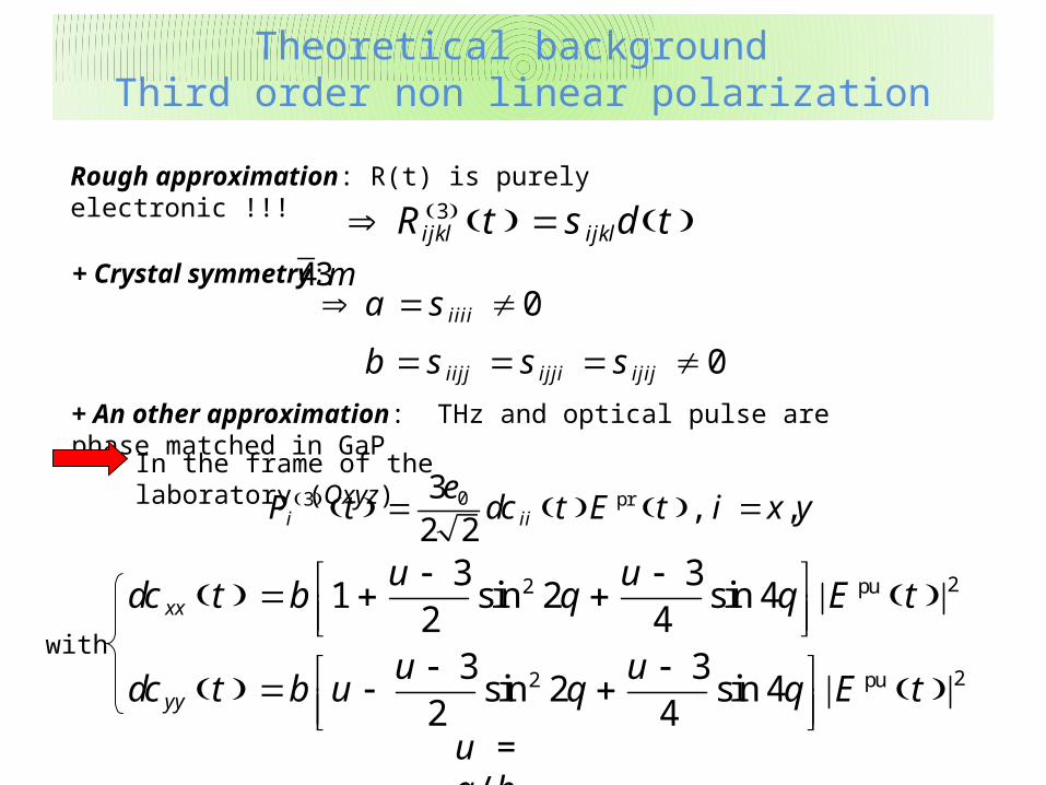
03 pr3
2 2, ,i iiP t t E t i x y
edc
22 pu
22 pu
3 31 2 4
2 43 3
2 42 4
sin sin
sin sin
xx
yy
u ut b E t
u ut b u E t
dc q q
dc q q
with
Rough approximation: R(t) is purely electronic !!! 3ijkl ijklR t ts d
+ Crystal symmetry: 43m0
0
iiii
iijj ijji ijij
a
b
s
s s s
+ An other approximation: THz and optical pulse are phase matched in GaP
In the frame of the laboratory (Oxyz)
u = a/b
Theoretical background Third order non linear polarization
Theoretical background Third order non linear polarization
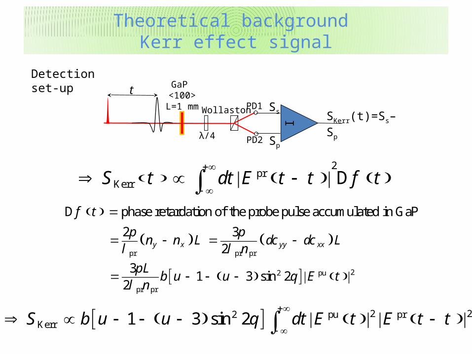
Detection set-upGaP
<100>L=1 mm
λ/4
Wollaston
tSs
Sp
PD1
PD2
I SKerr(t)=Ss–Sp
2
prKerrS dt E t tt t fD
phase retardation of the probe pulse accumulated in GaPtfD
pr pr pr
2 32y x yy xxn n L L
np p
dc dcl l
22 pu
pr pr
31 3 2
2sin
Lb u u E t
np
ql
2 22 pu prKerr 1 3 2sinS b u u dt E t E tq t
Theoretical background Kerr effect signal
Theoretical background Kerr effect signal
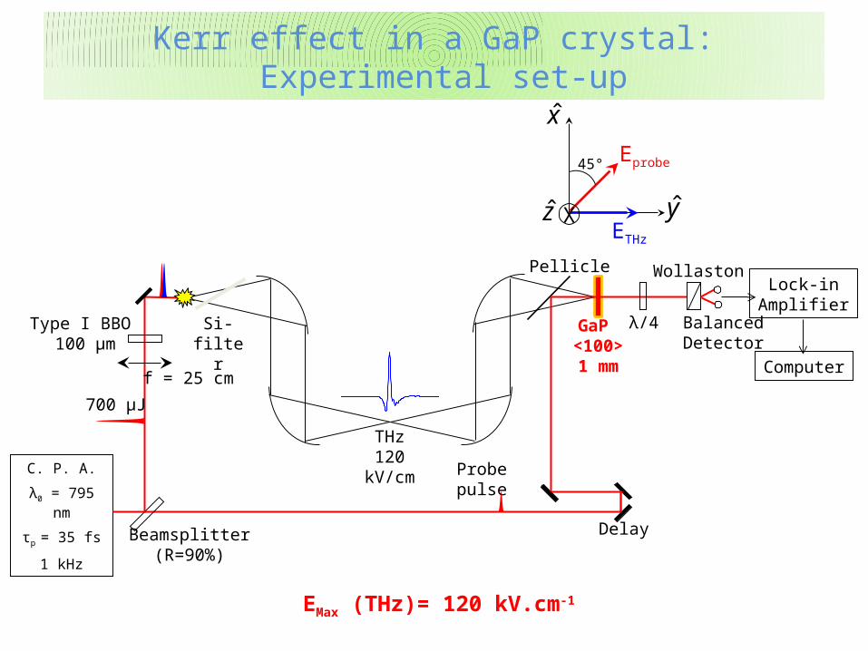
C. P. A.
λ0 = 795 nm
τp = 35 fs
1 kHzBeamsplitter
(R=90%)
THz120 kV/cm
GaP <100>1 mm
Pellicle
Si-filter λ/4
Wollaston
BalancedDetector
Lock-inAmplifier
Computer
Delay
Probepulse
700 µJ
Type I BBO 100 µm
f = 25 cm
Eprobe
ETHz
X
45°
x
yz
Kerr effect in a GaP crystal: Experimental set-up
Kerr effect in a GaP crystal: Experimental set-up
EMax (THz)= 120 kV.cm-1
-40 -20 0 20 40 60 80 100 120 140
Inte
gra
ted
Ker
r S
ign
al (
a.u
.)
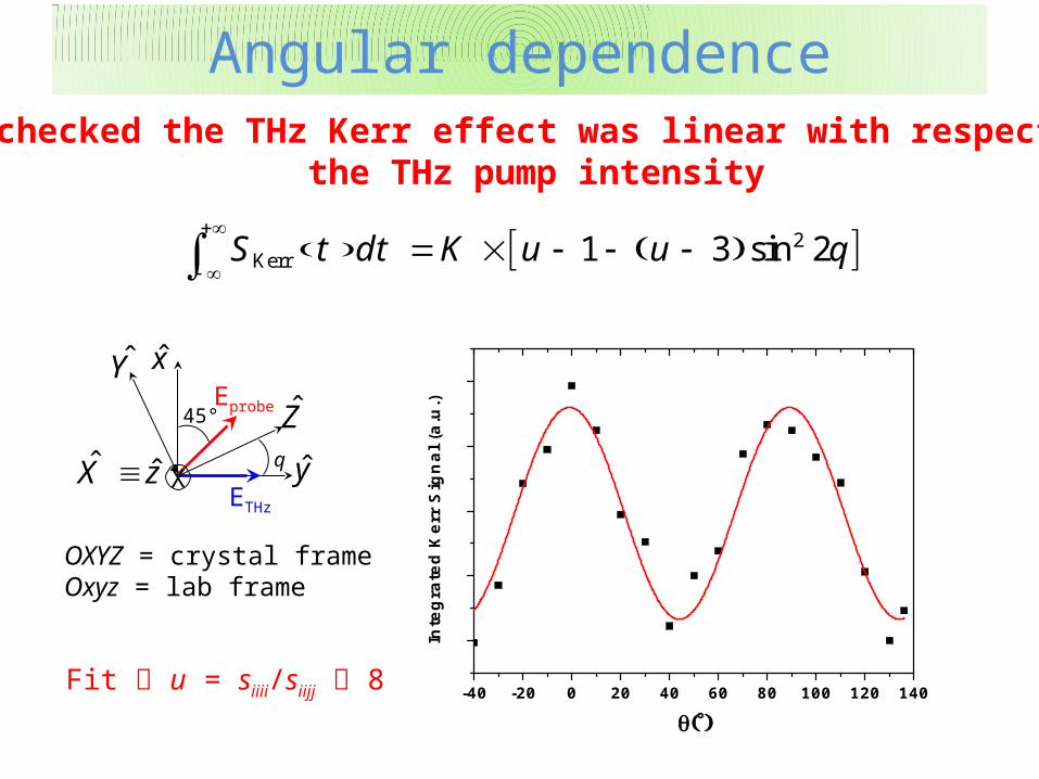
2Kerr 1 3 2sinS d K u ut t q
Eprobe
ETHz
X
45°
x
yˆ ˆX z
Z
Y
q
OXYZ = crystal frameOxyz = lab frame
Fit u = siiii/siijj 8
Angular dependenceAngular dependenceWe checked the THz Kerr effect was linear with respect to
the THz pump intensity
0 1 2 3 4 5
-0.5
0.0
0.5
1.0
1.5
2.0
2.5
SK
err (n
A)
delay (ps)
= 0°
0 1 2 3 4 5
-0.1
0.0
0.1
0.2
0.3
0.4
SK
err (
nA
)
delay (ps)
= 40°
0 1 2 3 4 5-0.2
0.0
0.2
0.4
0.6
0.8
1.0
SK
err (
nA
)
delay (ps)
= 90°
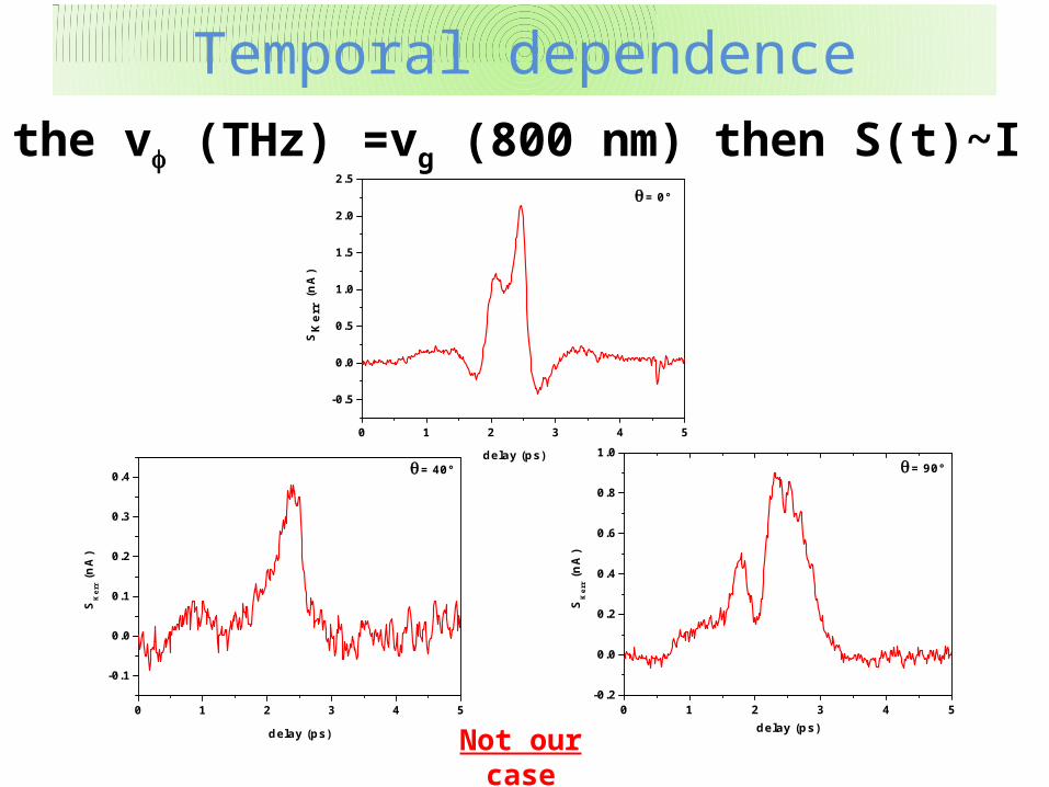
Temporal dependenceTemporal dependence
If the vf (THz) =vg (800 nm) then S(t)~I THz (t)
Not our case
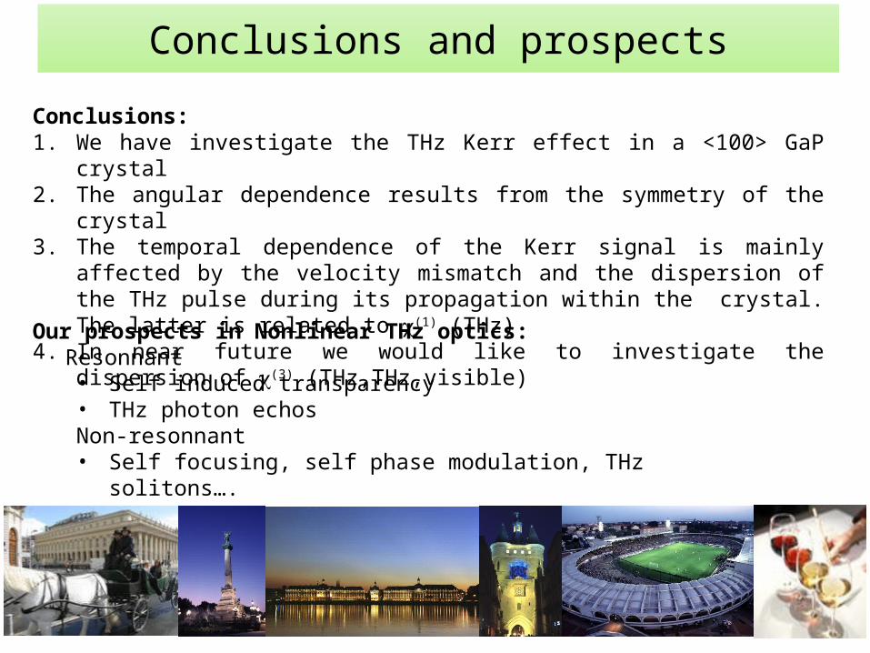
Conclusions and prospects
Conclusions:1. We have investigate the THz Kerr effect in a <100> GaP crystal2. The angular dependence results from the symmetry of the crystal 3. The temporal dependence of the Kerr signal is mainly affected by the velocity
mismatch and the dispersion of the THz pulse during its propagation within the crystal. The latter is related to c(1) (THz)
4. In near future we would like to investigate the dispersion of c(3) (THz,THz,visible)
Our prospects in Nonlinear THz optics:Resonnant• Self induced transparency• THz photon echosNon-resonnant• Self focusing, self phase modulation, THz solitons….
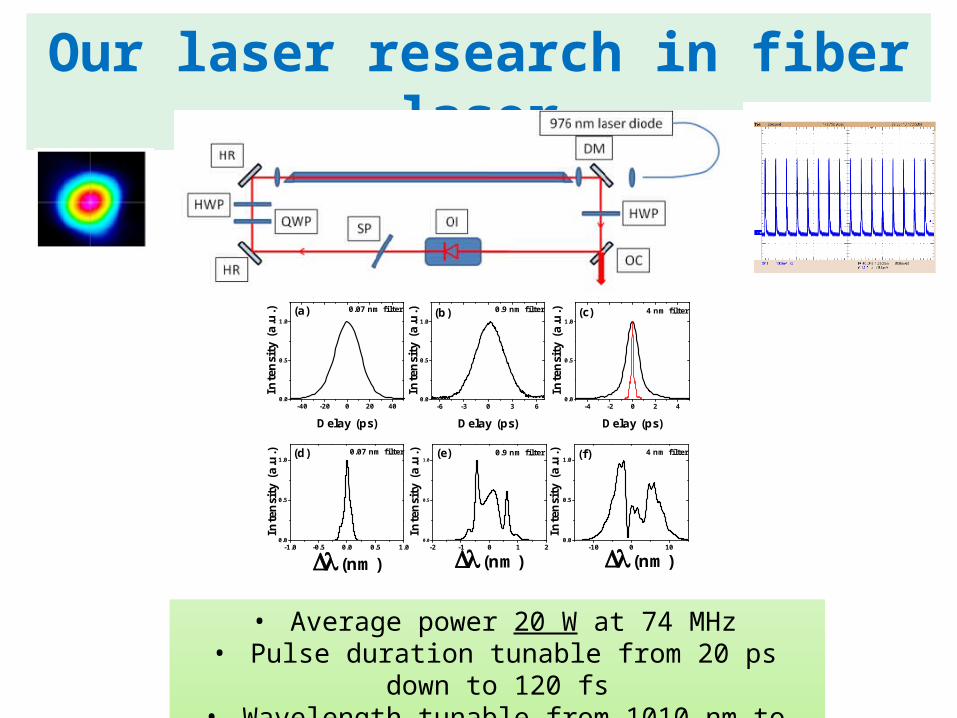
Our laser research in fiber laser
• Average power 20 W at 74 MHz• Pulse duration tunable from 20 ps down to 120 fs• Wavelength tunable from 1010 nm to 1080 nm
-40 -20 0 20 400.0
0.5
1.0
-6 -3 0 3 60.0
0.5
1.0
-4 -2 0 2 40.0
0.5
1.0
0.07 nm filter
Inte
nsi
ty (
a.u
.)
Delay (ps)
(a)
-1.0 -0.5 0.0 0.5 1.00.0
0.5
1.0(d) 0.07 nm filter
In
ten
sity
(a.
u.)
(nm)
(b) 0.9 nm filter
Inte
nsi
ty (
a.u
.)Delay (ps)
(c) 4 nm filter
Inte
nsi
ty (
a.u
.)
Delay (ps)
-2 -1 0 1 20.0
0.5
1.0(e) 0.9 nm filter
(nm)
In
ten
sity
(a.
u.)
-10 0 100.0
0.5
1.0 (f) 4 nm filter
(nm)
In
ten
sity
(a.
u.)
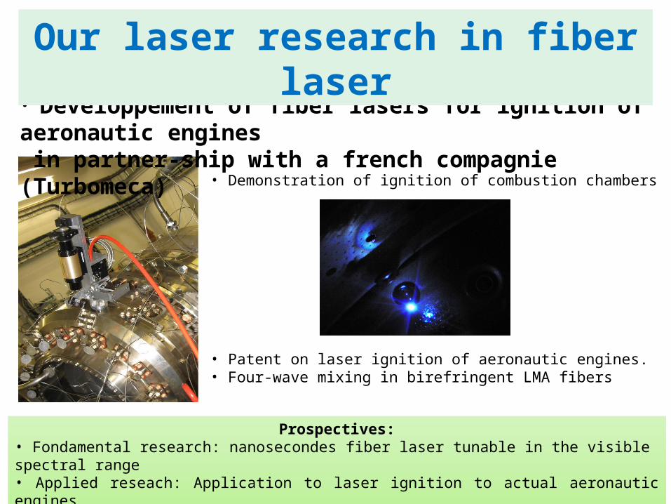
• Demonstration of ignition of combustion chambers
• Patent on laser ignition of aeronautic engines.• Four-wave mixing in birefringent LMA fibers
Prospectives:• Fondamental research: nanosecondes fiber laser tunable in the visible spectral range• Applied reseach: Application to laser ignition to actual aeronautic engines
• Développement of fiber lasers for ignition of aeronautic engines in partner-ship with a french compagnie (Turbomeca)
Our laser research in fiber laser