Embed Size (px)
Citation preview
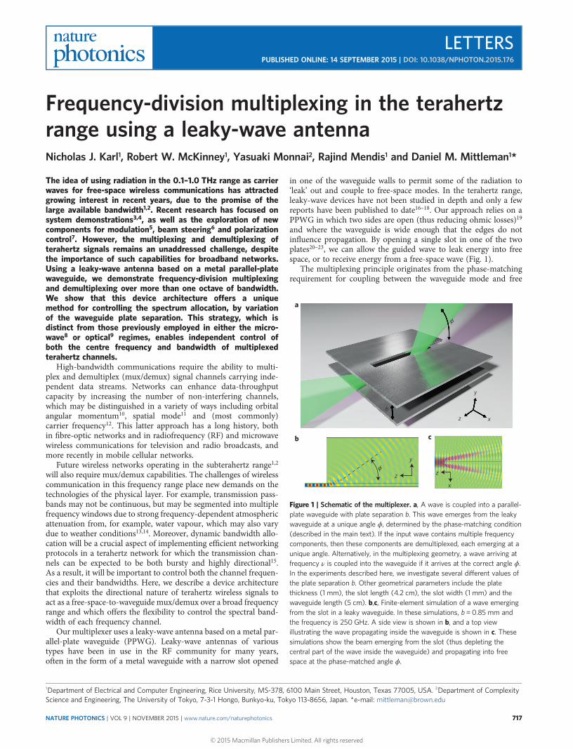
Frequency-division multiplexing in the terahertzrange using a leaky-wave antennaNicholas J. Karl1, Robert W. McKinney1, Yasuaki Monnai2, Rajind Mendis1 and Daniel M. Mittleman1*
The idea of using radiation in the 0.1–1.0 THz range as carrierwaves for free-space wireless communications has attractedgrowing interest in recent years, due to the promise of thelarge available bandwidth1,2. Recent research has focused onsystem demonstrations3,4, as well as the exploration of newcomponents for modulation5, beam steering6 and polarizationcontrol7. However, the multiplexing and demultiplexing ofterahertz signals remains an unaddressed challenge, despitethe importance of such capabilities for broadband networks.Using a leaky-wave antenna based on a metal parallel-platewaveguide, we demonstrate frequency-division multiplexingand demultiplexing over more than one octave of bandwidth.We show that this device architecture offers a uniquemethod for controlling the spectrum allocation, by variationof the waveguide plate separation. This strategy, which isdistinct from those previously employed in either the micro-wave8 or optical9 regimes, enables independent control ofboth the centre frequency and bandwidth of multiplexedterahertz channels.
High-bandwidth communications require the ability to multi-plex and demultiplex (mux/demux) signal channels carrying inde-pendent data streams. Networks can enhance data-throughputcapacity by increasing the number of non-interfering channels,which may be distinguished in a variety of ways including orbitalangular momentum10, spatial mode11 and (most commonly)carrier frequency12. This latter approach has a long history, bothin fibre-optic networks and in radiofrequency (RF) and microwavewireless communications for television and radio broadcasts, andmore recently in mobile cellular networks.
Future wireless networks operating in the subterahertz range1,2
will also require mux/demux capabilities. The challenges of wirelesscommunication in this frequency range place new demands on thetechnologies of the physical layer. For example, transmission pass-bands may not be continuous, but may be segmented into multiplefrequency windows due to strong frequency-dependent atmosphericattenuation from, for example, water vapour, which may also varydue to weather conditions13,14. Moreover, dynamic bandwidth allo-cation will be a crucial aspect of implementing efficient networkingprotocols in a terahertz network for which the transmission chan-nels can be expected to be both bursty and highly directional15.As a result, it will be important to control both the channel frequen-cies and their bandwidths. Here, we describe a device architecturethat exploits the directional nature of terahertz wireless signals toact as a free-space-to-waveguide mux/demux over a broad frequencyrange and which offers the flexibility to control the spectral band-width of each frequency channel.
Our multiplexer uses a leaky-wave antenna based on a metal par-allel-plate waveguide (PPWG). Leaky-wave antennas of varioustypes have been in use in the RF community for many years,often in the form of a metal waveguide with a narrow slot opened
in one of the waveguide walls to permit some of the radiation to‘leak’ out and couple to free-space modes. In the terahertz range,leaky-wave devices have not been studied in depth and only a fewreports have been published to date16–18. Our approach relies on aPPWG in which two sides are open (thus reducing ohmic losses)19
and where the waveguide is wide enough that the edges do notinfluence propagation. By opening a single slot in one of the twoplates20–23, we can allow the guided wave to leak energy into freespace, or to receive energy from a free-space wave (Fig. 1).
The multiplexing principle originates from the phase-matchingrequirement for coupling between the waveguide mode and free
a
b c
bz
z
y
y
z
x
ϕ
ϕ
x
Figure 1 | Schematic of the multiplexer. a, A wave is coupled into a parallel-plate waveguide with plate separation b. This wave emerges from the leakywaveguide at a unique angle ϕ, determined by the phase-matching condition(described in the main text). If the input wave contains multiple frequencycomponents, then these components are demultiplexed, each emerging at aunique angle. Alternatively, in the multiplexing geometry, a wave arriving atfrequency ν is coupled into the waveguide if it arrives at the correct angle ϕ.In the experiments described here, we investigate several different values ofthe plate separation b. Other geometrical parameters include the platethickness (1 mm), the slot length (4.2 cm), the slot width (1 mm) and thewaveguide length (5 cm). b,c, Finite-element simulation of a wave emergingfrom the slot in a leaky waveguide. In these simulations, b =0.85 mm andthe frequency is 250 GHz. A side view is shown in b, and a top viewillustrating the wave propagating inside the waveguide is shown in c. Thesesimulations show the beam emerging from the slot (thus depleting thecentral part of the wave inside the waveguide) and propagating into freespace at the phase-matched angle ϕ.
1Department of Electrical and Computer Engineering, Rice University, MS-378, 6100 Main Street, Houston, Texas 77005, USA. 2Department of ComplexityScience and Engineering, The University of Tokyo, 7-3-1 Hongo, Bunkyo-ku, Tokyo 113-8656, Japan. *e-mail: [email protected]
LETTERSPUBLISHED ONLINE: 14 SEPTEMBER 2015 | DOI: 10.1038/NPHOTON.2015.176
NATURE PHOTONICS | VOL 9 | NOVEMBER 2015 | www.nature.com/naturephotonics 717
© 2015 Macmillan Publishers Limited. All rights reserved

space. For the lowest-order transverse-electric (TE1) mode of aPPWG, the frequency-dependent propagation constant is given by24
kPPWG = k0
������������1 −
c02bv
( )2√(1)
where b is the plate separation and k0 is the wavevector for freespace, k0 = 2πv/c0. If the waveguide has a slot in one plate, then radi-ation can couple from the guided mode to free space with the phase-matching constraint that k0cosϕ = kPPWG. Here, ϕ is the propagationangle of the free-space mode relative to the waveguide propagationaxis. Because of the frequency dependence of kPPWG, this conditionresults in an angle-dependent emission frequency:
v(f) =c0
2b sinf(2)
Numerical simulations (Fig. 1b,c) illustrate the well-defined beamemerging from the slot and the corresponding depletion of theguided mode inside the waveguide when this phase-matching con-dition is fulfilled. For a given acceptance angle, Δϕ, of a receiverlocated in the far field of the slot, the spectral bandwidth of agiven channel is described by
Δv(f) =dvdf
∣∣∣∣∣∣∣∣Δf =
c02b sinf tanf
Δf (3)
Conversely, when operated as a receiver, incoming free-space wavesarriving at an angle ϕ couple into the waveguide only if they have thecorrect frequency, as defined by equation (2). These incoming chan-nels will be collected with a bandwidth determined by the numericalaperture of the incoupled radiation, according to equation (3). This
waveguide can therefore act as either a multiplexer or a demulti-plexer between directional free-space beams and a single-mode waveguide.
We first characterize the leaky wave from a waveguide with per-fectly parallel plates. The results (Fig. 2) show good agreement withequations (2) and (3) for both the transmit (demux) and receive (mux)configurations. Figure 3 shows the first experimental demonstration ofthe multiplexing of two terahertz input channels, using two indepen-dent broadband illumination sources and a single receiver.
Next, we consider a waveguide in which the plate separation isnot constant, but varies with position inside the waveguide. Thispossibility provides enormous flexibility in the device design andresults in new and important multiplexing capabilities. Althoughin this case the plates are no longer strictly parallel, we preservesingle-mode propagation as long as the change in plate separationis adiabatic with respect to the wavelength25,26.
We first study the case where b varies along the waveguide propa-gation axis (the z axis). The frequency of the incoupled channel nowdepends both on ϕ and on z0, the location of the illumination pointalong the waveguide axis. Thus, we can achieve frequency tuning at afixed angle, simply by translating the waveguide (and detector) rela-tive to the input beam, along the z axis (that is, varying z0). Wedemonstrate this effect using a waveguide with two flat plates set ata 2° relative angle, so that b(z) is simply a linear function of z (Fig. 4).
Although it is clear that mechanical translation of the multi-plexer is not a practical method for achieving high-speed frequencytuning, this result demonstrates the extra degree of freedom that canbe exploited in designing a multiplexer, with input coupling opticschosen to dictate the input angle and axis for each channel. If weallow variation in both the input illumination locations andangles, we have almost arbitrary design flexibility. For example, wecan design an equally spaced array of frequency bands each with
a b
Tx
Rx
ϕ
Freq
uenc
y (T
Hz)
Angle (°)
10 20 30 40 50 60 70 800.0
0.1
0.2
0.3
0.4
0.5
1 mm
2 mm
4 mm
ϕ
TxFr
eque
ncy
(TH
z)
Angle (°)10 20 30 40 50 60 70 80
0.0
0.1
0.2
0.3
0.4
0.5
2 mm
1 mm
4 mm
Band
wid
th (G
Hz)
Angle (°)
20 40 60 800
20
40
60
80
1 mm
4 mm
Band
wid
th (G
Hz)
Angle (°)20 40 60 80
0
20
40
60
80
1 mm
4 mm
Rx
Figure 2 | Free-space-to-waveguide coupling. a, Measured terahertz radiation collected by the leaky waveguide when operating as a receiver (multiplexer),as a function of the angle of the incident radiation. The schematic shows the measurement set-up, with transmitter Tx mounted on a pivoting rail to vary theinput angle. Results are shown for several different values of plate separation b. Inset: measured spectral 3 dB bandwidths at each angle. The measuredresults are all in good agreement with predictions (solid curves), using an acceptance aperture of Δϕ =0.25. b, Similar to a, except here the leaky waveguideis operated as a transmitter (demultiplexer), as illustrated in the schematic. Here, receiver Rx is mounted on a pivoting rail. Error bars represent the standarderror of the Gaussian-curve fit when determining the 3 dB bandwidth.
LETTERS NATURE PHOTONICS DOI: 10.1038/NPHOTON.2015.176
NATURE PHOTONICS | VOL 9 | NOVEMBER 2015 | www.nature.com/naturephotonics718
© 2015 Macmillan Publishers Limited. All rights reserved
identical bandwidth, as is typical in fibre-based wavelengthdivision multiplexing (WDM) systems (Supplementary Information).We have previously shown that almost any function b(z) can beimplemented by shaping one waveguide plate using high-resolutionthree-dimensional printing followed by the application of a metalliccoating26.
We next consider the case in which the plate separation b variesalong the transverse dimension x, rather than along the waveguidepropagation axis z. At a given input angle the input coupling con-dition (2) can be satisfied for a range of frequencies determinedby the size of the variation of b(x) in the region underneath theslot. If we define the range of values of b as Δb, then the range offrequencies that satisfy equation (2) is
δn =c0
2b2 sinfΔb (4)
The bandwidth of the multiplexed channel is then determined byboth the range of frequencies that satisfy the phase-matching con-dition and by their bandwidths, varying roughly as
Δnchannel ≈�����������Δn2 + δn2
√(5)
As above, Δb could be varied by tilting the lower waveguide plate.However, a better alternative is to shape the lower waveguide plateso that the variation in b(x) is symmetric with respect to the slotin the upper plate. For example, Fig. 5a illustrates a trench withcylindrical curvature, with the largest value of b centred on theslot axis. This geometry has a significant advantage, in thatthe cylindrical curvature improves the collimation and guiding
of the waveguide, by counteracting diffraction in the x–zplane27,28. Using plates with several different trench depths, wedemonstrate the capability for bandwidth tuning by varying Δb(Fig. 5).
An important issue in any mux/demux design is that of losses. Inour device, there are several possible sources of loss, including thecoupling between free space and the waveguide mode at the inputand output and the waveguide propagation loss. In our case, thepropagation losses are quite small, especially for a propagation dis-tance of only a few centimetres (for example, less than 1 dB for theexperiment shown in Fig. 2)29. The power coupling efficiency ofthe TE1 waveguide mode to a free-space Gaussian beam canexceed 99%30. Thus, the only significant source of attenuation isthe coupling through the slot. In our receiver experiments (forexample, Fig. 3), this coupling introduces ∼9 dB of loss, due to a sig-nificant mismatch between the incoming (focusing) beam spot sizeand the width of the slot. However, this is far from optimized in ourset-up. Significant improvements can be expected with carefuldesign of the optical system.
In conclusion, we have investigated the radiation properties of aleaky PPWG in the terahertz range. We demonstrate mux/demuxover an octave of bandwidth in the sub-terahertz range. Unlikeother leaky-wave devices used for mux/demux at lower frequencies,our approach does not rely on the transparency of dielectricmaterials and is therefore scalable to the terahertz range.Moreover, varying the plate separation b(x,z) offers a new andpowerful method for controlling the frequency and bandwidth ofmultiplexed channels. Future designs could incorporate a variationin the width of the slot along its length, to control the leakage rateand thereby compensate for relative changes in multiplexing effi-ciency or in the spatial profile of different frequency channels8.We can also envision the implementation of an active device,based on electrostatically controlled microelectromechanical com-ponents, for dynamically varying the depth and curvature of thewaveguide. Because of the large design flexibility, we anticipatethat this multiplexing strategy could play a central role in futureterahertz wireless systems.
Tx1
Tx2
0.1 0.2 0.3 0.4 0.50.00
0.05
0.10
0.15
0.20
0.25
Spec
tral
am
plitu
de (a
.u.)
Frequency (THz)
Tx2Tx1
150
200
250
300
350Fr
eque
ncy
(GH
z)
Incidence angle (°)
20 40 60 80
Rx
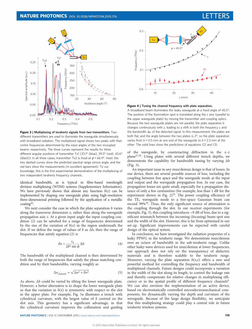
Figure 3 | Multiplexing of terahertz signals from two transmitters. Twodifferent transmitters are used to illuminate the waveguide simultaneouslywith broadband radiation. The multiplexed signal shows two peaks with theircentre frequencies determined by the input angles of the two incoupledbeams, respectively. The three curves represent the results for threedifferent angular positions of transmitter Tx1 (33.1° (blue), 39.5° (red), 43.6°(black)). In all three cases, transmitter Tx2 is fixed at ϕ= 66.9°. Inset: thetwo dashed curves show the predicted spectral range versus angle, and thered bars show the measurements (in excellent agreement). To ourknowledge, this is the first experimental demonstration of the multiplexing oftwo independent terahertz frequency channels.
Freq
uenc
y (T
Hz)
z (mm)10 20 30 40
0.0
0.1
0.2
0.3
ν
Δν
Tx
Rx
ϕ = 45.5°
z
Figure 4 | Tuning the channel frequency with plate separation.A broadband beam illuminates the leaky waveguide at a fixed angle of 45.5°.The position of the illumination spot is translated along the z axis (parallel tothe upper waveguide plate) by moving the transmitter and coupling optics.Because the two waveguide plates are not parallel, the plate separation bchanges continuously with z, leading to a shift in both the frequency ν andthe bandwidth Δν of the detected signal. In this measurement, the plates areboth flat, and the angle between the two plates is 2°, so the plate separationvaries from b = 0.5 mm at one end of the waveguide to b = 2.3 mm at theother. The solid lines show the predictions of equations (2) and (3).
NATURE PHOTONICS DOI: 10.1038/NPHOTON.2015.176 LETTERS
NATURE PHOTONICS | VOL 9 | NOVEMBER 2015 | www.nature.com/naturephotonics 719
© 2015 Macmillan Publishers Limited. All rights reserved

MethodsMethods and any associated references are available in the onlineversion of the paper.
Received 9 February 2015; accepted 11 August 2015;published online 14 September 2015
References1. Piesiewicz, R. et al. Short-range ultra broadband terahertz communications:
concepts and perspectives. IEEE Antennas Propag. Mag. 49, 24–39 (2007).2. Kleine-Ostmann, T. & Nagatsuma, T. A review on terahertz communications
research. J. Infrared Milli. Terahertz Waves 32, 143–171 (2011).3. Song, H.-J. et al. 24 Gbit/s data transmission in 300 GHz band for future
terahertz communications. Electron. Lett. 48, 953–954 (2012).4. Koenig, S. et al. Wireless sub-THz communication system with high data rate.
Nature Photon. 7, 977–981 (2013).5. Chen, H.-T. et al. Active terahertz metamaterial devices. Nature 444,
597–600 (2006).6. Monnai, Y. et al. Terahertz beam steering and variable focusing using
programmable diffraction gratings. Opt. Express 21, 2347–2354 (2013).7. Shuvaev, A. et al. Electric field control of terahertz polarization in a multiferroic
manganite with electromagnons. Phys. Rev. Lett. 111, 227201 (2013).8. Oliner, A. A. & Jackson, D. R. in Antenna Engineering Handbook (ed. Volakis,
J. L.) Ch. 11 (McGraw-Hill, 2007).9. Keiser, G. Optical Fiber Communications 4th edn (McGraw-Hill, 2011).10. Yan, Y. et al. High-capacity millimetre-wave communications with orbital
angular momentum multiplexing. Nature Commun. 5, 4876 (2014).11. Luo, L.-W. et al. WDM-compatible mode-division multiplexing on a silicon
chip. Nature Commun. 5, 3069 (2014).12. Acampora, A. S. An Introduction to Broadband Networks (Plenum, 1994).13. Su, K., Moeller, L., Barat, R. B. & Federici, J. F. Experimental comparison of
performance degradation from terahertz and infrared wireless links in fog. J. Opt.Soc. Am. A 29, 179–184 (2012).
14. Suen, J. Y., Fang, M. T. & Lubin, P. M. Global distribution of water vapor andcloud cover—sites for high-performance THz applications. IEEE Trans. THz Sci.Technol. 4, 86–100 (2014).
15. Sabharwal, A., Khoshnevis, A. & Knightly, E. Opportunistic spectral usage:bounds and a multi-band CSMA/CA protocol. IEEE/ACM Trans. Netw. 15,533–545 (2007).
16. Monnai, Y. et al. Terahertz beam focusing based on plasmonic waveguidescattering. Appl. Phys. Lett. 101, 015116 (2012).
17. Hon, P. W. C., Liu, Z., Itoh, T. & Williams, B. S. Leaky and bound modes interahertz metasurfaces made of transmission-line metamaterials. J. Appl. Phys.113, 033105 (2013).
18. Esquius-Morote, M., Gomez-Diaz, J. S. & Perruisseau-Carrier, J. Sinusoidallymodulated graphene leaky-wave antenna for electronic beam scanning at THz.IEEE Trans. THz Sci. Technol. 4, 116–122 (2014).
19. Mendis, R. & Grischkowsky, D. Undistorted guided-wave propagation ofsubpicosecond terahertz pulses. Opt. Lett. 26, 846–848 (2001).
20. Keshavamurthy, T. L. & Butler, C. M. Characteristics of a slotted parallel-platewaveguide filled with a truncated dielectric. IEEE Trans. Antennas Propag. 29,112–117 (1981).
21. Chuang, C. W. Generalized admittance matrix for a slotted parallel-platewaveguide. IEEE Trans. Antennas Propag. 36, 1227–1230 (1988).
22. Lee, C. -W. & Son, H. Periodically slotted dielectrically filled parallel-platewaveguide as a leaky-wave antenna: E-polarization case. IEEE Trans. AntennasPropag. 47, 171–178 (1999).
23. Lee, J.-I., Cho, U.-H. & Cho, Y.-K. Analysis for a dielectrically filled parallel-platewaveguide with finite number of periodic slots in its upper wall as a leaky-waveantenna. IEEE Trans. Antennas Propag. 47, 701–706 (1999).
24. Mendis, R. & Mittleman, D. M. A 2D artificial dielectric with 0 < n < 1 for theterahertz region. IEEE Trans. Microw. Theory Techn. 58, 1993–1998 (2010).
25. Mendis, R., Liu, J. & Mittleman, D. M. THz mirage: deflecting terahertz beamsin an inhomogeneous artificial dielectric based on a parallel-plate waveguide.Appl. Phys. Lett. 101, 111108 (2012).
26. Liu, J., Mendis, R. & Mittleman, D. M. A Maxwell’s fish eye lens for the terahertzregion. Appl. Phys. Lett. 103, 031104 (2013).
27. Mbonye, M., Mendis, R. & Mittleman, D. M. Inhibiting the TE1-modediffraction losses in terahertz parallel-plate waveguides using concave plates.Opt. Express 20, 27800–27809 (2012).
28. Mbonye,M.,Mendis, R.&Mittleman,D.M.MeasuringTE1mode losses in terahertzparallel-plate waveguides. J. Infrared Milli. Terahertz Waves 34, 416–422 (2013).
29. Mendis, R. & Mittleman, D. M. Comparison of the lowest-order transverse-electric (TE1) and transverse-magnetic (TEM) modes of the parallel-platewaveguide for terahertz pulse applications.Opt. Express 17, 14839–14850 (2009).
30. Mendis, R. & Mittleman, D. M. An investigation of the lowest-order transverse-electric (TE1) mode of the parallel-plate waveguide for THz pulse propagation.J. Opt. Soc. Am. B 26, 6–13 (2009).
AcknowledgementsThe authors thank K. Reichel for contributions. This work was supported by the USNational Science Foundation and the W.M. Keck Foundation.
Author contributionsAll of the authors contributed to the conception and design of these experiments. R.W.M.and N.J.K. built the set-up and collected and analysed the data. All authors contributed tothe discussions and to the writing of the manuscript.
Additional informationSupplementary information is available in the online version of the paper. Reprints andpermissions information is available online at www.nature.com/reprints. Correspondence andrequests for materials should be addressed to D.M.M.
Competing financial interestsThe authors declare no competing financial interests.
a b c
Freq
uenc
y (T
Hz)
Δb (mm)
Centre frequency
Bandwidth
0.00 0.10 0.20 0.300.0
0.1
0.2
0.3
Normalized frequency (THz)
Nor
mal
ized
inte
nsity
−0.1−0.2 0.0
Δb = 0 mmΔb = 0.1 mmΔb = 0.2 mm
10−4
10−3
10−2
10−1
100
0.1 0.2
y
xz
b
Δb
Figure 5 | Spectrum allocation tuning with waveguide geometry. a, Illustration of the variation in b(x) provided by a cylindrically shaped trench in the lowerwaveguide plate, with plate separation variation Δb as indicated. b, Spectra of radiation measured at the waveguide output, for several different geometricalconfigurations of the lower waveguide plate (that is, different values of Δb). Plate separation b and the radius of curvature of the cylindrical trench are heldconstant, and only the trench depth Δb is varied. To emphasize the bandwidth variation, these curves have been shifted so that their central peaks align, andare normalized to unity height. c, We find good agreement between the measured bandwidth of these signals, Δνchannel, and the predicted variation(solid curve) with Δb. Varying Δb also changes the average value of b underneath the slot, so the central frequency of the incoupled wave shifts slightly, aspredicted.
LETTERS NATURE PHOTONICS DOI: 10.1038/NPHOTON.2015.176
NATURE PHOTONICS | VOL 9 | NOVEMBER 2015 | www.nature.com/naturephotonics720
© 2015 Macmillan Publishers Limited. All rights reserved

MethodsAll the experiments were performed using a commercial terahertz time-domainspectrometer (TDS). This is a conventional TDS system, which uses a femtosecondlaser to generate and detect single-cycle terahertz pulses in lens-coupledphotoconductive antennas fabricated on low-temperature-grown semiconductingsubstrates. These antennas were fibre-coupled for ease of repositioning. Spectra wereobtained from measured time-domain waveforms via numerical Fourier transform.In these measurements, the spectral resolution was ∼3 GHz, limited by the length ofthe optical delay line used to measure the waveforms in the time domain. Thespectral content of the generated terahertz pulses exceeded 1 THz. For the angle-dependent measurements, the transmitter (or receiver) was mounted on a pivoting
rail, with the pivot situated directly below the edge of the leaky-wave antenna slot, sothat the angle of incidence (or emission) could be varied without changing any othergeometrical parameters (for example, the propagation distance for the guided waveinside the waveguide).
The waveguides used in this study were fabricated with conventionalmachining of aluminium stock. We have previously determined that the surfaceroughness of high-quality as-purchased aluminium plates is sufficiently small thatroughness losses are negligibly small at frequencies below 1 THz, even in awaveguide with a length greater than 1 m. These aluminium parts were thereforeused without further modification or polishing. Machining tolerances weretypically ∼25 μm.
NATURE PHOTONICS DOI: 10.1038/NPHOTON.2015.176 LETTERS
NATURE PHOTONICS | www.nature.com/naturephotonics
© 2015 Macmillan Publishers Limited. All rights reserved