Embed Size (px)
Citation preview

Terahertz birefringent gratings for filtering
and dispersion compensation
Muhammad Talal Ali Khan1*, Haisu Li 2*, Yajing Liu2, Gang-Ding Peng3, and Shaghik
Atakaramians1
1Shaghik’s THz Group, School of Electrical Engineering and Telecommunications, UNSW Sydney, New South
Wales 2052, Australia 2Key Laboratory of All Optical Network and Advanced Telecommunication Network of EMC, Institute of
Lightwave Technology, Beijing Jiaotong University, Beijing 100044, China * Contributed equally to this work.
The recent development of the terahertz waveguide makes it an excellent
platform for integrating many intriguing functionalities, which offers
tremendous potential to build compact and robust terahertz systems. In the
context of next-generation high-speed communication links at the terahertz
band, engineering the dispersion and birefringence of terahertz waves is
essential. Here, we experimentally demonstrate subwavelength birefringent
waveguide gratings based on the low-loss cyclic olefin copolymer exploiting
micro-machining fabrication techniques. Asymmetric cross-section and
periodic-structural modulation along propagation direction are introduced to
achieve birefringent THz grating for filtering and dispersion compensation.
Because of strong index modulation in the subwavelength fiber, a high
negative group velocity dispersion of -188 (-88) ps/mm/THz is achieved at 0.15
THz for x-polarization (y-polarization), i.e., 7.5 times increase compared to the
state-of-the-art reported to date. Such high negative dispersion is realized in
a 43 mm grating length, which is less than half of the length reported until now
(e.g., 100 mm). Further, the subwavelength fiber grating filters two orthogonal
polarization states and exhibits transmission dips with 8.5-dB and 7.5-dB
extinction ratios for x and y polarization, respectively. Our experiment
demonstrates the feasibility of using polymer-based terahertz gratings as a
dispersion compensator in terahertz communications and steering polarized
terahertz radiations for polarization-sensitive THz systems.

ver the last few years, terahertz (THz) technology has evolved
dramatically due to the successful implementation of interesting
applications such as high-speed communication, non-destructive
material inspection, biological sensing, security, and many others [1]. These
diverse applications require not only sources and detectors for the generation
and detection of THz waves but also the waveguide components [2]. Although
the development of various THz waveguide structures has progressed quickly
between 0.1 THz to 1 THz frequencies range [3, 4], a key challenge is that most
of the polymer materials have high absorption losses. Over the past decades,
mostly subwavelength THz fibers (propagation mainly in the air cladding) [5-
7] or air-core structures with exotic cladding designs (propagation in the air
core) [8-11] have been demonstrated as the promising platform to mitigate
high transmission losses of polymers. To effectively manipulate THz waves,
waveguide-based functional devices including filters, couplers, polarizers,
modulators, sensors [12-17] are also particularly important to realize the THz
applications like wireless communication systems [16], THz spectroscopy [18],
sensing systems [19] and high-resolution imaging [20]. Out of many
aforementioned devices, steering polarization states are also crucial for
polarization-sensitive THz systems, which can be effectively realized via
designing birefringent waveguides [6].
The waveguide-based gratings offer important functionalities such as
bandstop/bandpass filtering [12, 21-23] and dispersion manipulation, which
have been extensively applied at optic communication band (i.e., the well-
known optical fiber gratings) [24], while the demonstrations at THz
frequencies are still limited despite such intriguing applications [16, 18-20]. In
2012, a THz notch-type Bragg grating written on a polymer fiber was reported
for filtering applications, however, one polarized state was found to be
stronger than other polarization states due to fabrication limitations — laser
cutting technique caused the asymmetric distribution of etched gratings on
circular rod [25]. Another THz waveguide grating has been demonstrated
based on a plasmonic two-wire waveguide accompanied by paper grating, yet
it only filters the wave perpendicular to the paper grating [26]. Subsequently,
Ma et al. [16] demonstrated hollow-core THz metallic waveguide Bragg
gratings for dispersion compensation in THz communication links. A negative
dispersion of -25 ps/THz/mm at 0.14 THz was achieved in a 100 mm long
O

grating device. However, such a circular waveguide is polarization-
independent and has weak modulation due to an oversized core. We notice
that most of the reported THz gratings’ either filter one polarization state or
are polarization independent. Recently, motivated by the demands of
polarization-sensitive THz systems, we have numerically proposed a THz
subwavelength birefringent waveguide grating as a stopband filter [12]. This
grating filters two orthogonal polarization states simultaneously and is
expected to be a promising candidate for upcoming THz communications. For
example, the wireless transmission capacity can be doubled by polarization-
division-multiplexing techniques when two orthogonal polarized THz waves
propagate simultaneously in a multiple-input multiple-output THz wireless
transmission system [27].
In this work, we experimentally demonstrate THz birefringent grating,
which filters two polarization states simultaneously and offers large negative
dispersion in the shortest length. Our experimental results confirm the
filtering of two orthogonal modes at 0.15 THz. The measurements show 8.5-
dB and 7.5-dB extinction ratios (ER) with a 5 GHz full-width at half-maximums
(FWHM) for x-polarization and y-polarization respectively. We also
demonstrate a large negative group velocity dispersion of -188 ps/mm/THz in
a 43 mm device length, which is more than 7.5 times higher dispersion in less
than half of the length reported to date in THz waveguide-based gratings. Our
demonstration shows a promising path for filtering and dispersion
compensation in future THz communication links. In this paper, we present
the design and the fabrication of THz birefringent grating in Section 2. In
Section 3, the characterization setup, transmission characteristics, and group
velocity dispersion are investigated. In Section 4, we discuss and conclude the
findings.
Figure 1 (a) presents a schematic of the subwavelength birefringent
waveguide-based grating structure, where the THz waves propagate along the
z-axis (longitudinal direction). The waveguide-based grating is constructed by
introducing the structural perturbation periodically along the propagation
direction. The geometrical birefringence in rectangular waveguide cross-
section supports two orthogonally polarized modes i.e., x-polarization (x-pol.)
and y-polarization (y-pol.). As shown in the inset of Fig. 1 (a), the single grating
unit consists of large (C1) and small (C2) sized rectangular cells and supports

modes with effective refractive indices of neff1 and neff2, respectively. This
results in periodic structural modulation due to resonant mode coupling along
a longitudinal direction. Such coupling shows a stopband profile in the
transmission spectrum, where the Bragg frequency (fB) of the stopband can be
estimated by Bragg condition as follows [12]:
2𝑓𝐵(𝑛𝑒𝑓𝑓1𝐿1 + 𝑛𝑒𝑓𝑓2𝐿2) = 𝑚𝑐 (1)
where m is an integer (m= 1 in this work), c is the speed of light in vacuum, L1
and L2 are the lengths of the C1 and C2, respectively.
To achieve a target frequency band at 0.15 THz, we design waveguide
gratings according to Eq. (1) with appropriate cross-sectional parameters of
d1x, d1y, d2x, d2y. The grating pitch (𝛬) and total grating length (period number
of N) are equal to L1 + L2 and 𝑁 × 𝛬, respectively. We fabricated two gratings
with period numbers 29 and 45. The gratings were manufactured using
micromachining techniques. The photographs of the two fabricated samples
are shown in Fig. 1 (b), where the total measured lengths are 30 mm (denoted
as short) and 43 mm (denoted as long), respectively. The segments were
machined on a Kira Super Mill M2 which is a 3-axis precision (2 µm) milling
machine using a Fanuc31i controller [28]. The cutting programs used on the
Kira were created using SolidCAM CAD/CAM software, which also optimized
the cutting parameters. The samples were inspected using an Olympus Laser
scanning microscope [29]. The microscope images of short and long samples
are shown in Fig. 1 (c). To reduce propagation losses, we select a low-loss cyclic
olefin copolymer (COC) material with the tradename of TOPAS® COC 5013L-10
[30]. We use a COC sheet as it is relatively easier to cut the grating using the
micromachining process. The thickness of the sheet is 2 mm. We utilize THz
time-domain spectroscopy (THz-TDS, see details in Section 3.1) to characterize
the properties of the COC. Figure 2 (a) shows the measured (experiment
fitting) refractive index and absorption coefficient of COC. The index of
refraction is 1.536 at 0.15 THz and constant up to 1 THz. As expected, we
observed a very low absorption coefficient (0.0027 1/mm) at 0.15 THz. Based
on the material properties, the extracted complex refractive index of COC at
0.15 THz is 1.538+0.0065i, which is used in the Lumerical FDTD simulations
[31]. The measured parameters of short and long fabricated samples are

summarized in Table 1. We will discuss the impact of fabrication deviations on
the performance of grating in Section 3.2.
Table 1. Measured parameters of the fabricated gratings samples
Parameter Short grating Long grating
L1(µm) 580 ± 10 580 ± 10
L2(µm) 240 ± 20 240 ± 10
d1x(µm) 1340 ± 50 1300 ± 20
d2x(µm) 865 ± 40 906 ± 30
d1y(µm) 938 ± 40 1020 ± 20
d2y(µm) 606 ± 50 711 ± 10
Experimental Setup
We employ a THz-TDS system (Menlo TeraSmart [32]) to characterize the
performance of fabricated gratings. Figure 2 (c) shows the image of the
transmission characterization setup. The measured bandwidth of the THz-TDS
system is from 0.1 THz to 3.5 THz with over 65 dB of dynamic range. The THz
pulse is generated by the fiber-coupled THz antenna that is biased and
irradiated by an ultrafast femtosecond laser. Note that the THz source and
detector are linearly polarized, oriented along the y-direction in the setup. We
coupled the free-space propagation of THz pulse into the grating samples by
employing a pair of TPX lenses (TPX: polymethylpentene lens with a focal
length of 50 mm). Before the sample, a pinhole of 1.5 mm diameter is used,
to align the grating to the center of the beam. We use a dielectric foam to hold
the gratings, as shown in the inset of Fig. 2 (c). We investigate different
dielectric foams and, has chosen the foam with the closet refractive index to
air, [see Fig. 2(b)], which is expected to exhibit a negligible effect on the
transmission properties of the gratings. The measured properties of the foam
can be seen in Fig. 2 (b) which shows a refractive index of 1.004 and low losses
of 0.003 1/mm in the vicinity of 0.15 THz. It should be noted that the two
polarizations are measured by rotating the waveguide grating sample

orthogonally. After passing through the sample under test, the beam is
recollimated and focused into the detector (THz antenna) by an identical pair
of lenses.
Transmission Measurements
Figures 3 (a) and 3 (b) show the transmission spectra of the short and long
gratings for x- and y-polarizations, where the solid and dashed curves
represent measured and numerical results, respectively. For short grating [Fig.
3(a)], the measured reflective frequencies of x- and y-polarizations are at
0.152 THz and 0.155 THz, with ERs of 5.8-dB and 5.0-dB, respectively. Note
that, we consider averaged transmission outside the stopbands (green dashed
line) for an approximate evaluation of experimental ERs for both polarizations.
The FWHM of the stopbands are 8 (9) GHz, for x-pol. (y-pol.). For long grating
[Fig. 3(b)], 8.5- and 7.5-dB ERs are observed for x-pol. and y-pol., respectively,
and FWHM of 5 GHz for both polarizations. The measure reflective frequencies
of long grating for x-pol. (y-pol.) are at 0.1504 (0.1528) THz. As expected,
increasing the grating length leads to high ER and eventually shows strong
modulation strength. This shows that the index modulation of the unit cell of
the short grating is weaker than the long grating which results in different
FWHMs of two gratings.
In general, there is a good agreement between measured (solid curves in
Fig. 3) and numerically calculated (dotted curves in Fig. 3) stopband positions
of two gratings. The stopband positions of the short grating are the same as
of numerical, while a very small deviation of 0.13 % is observed between the
simulation and experiment stopband of the long grating (x-pol. only). In terms
of ERs and FWHMs, there is a slight mismatch in the measured results when
compared to numerical simulations. For example, the x- and y-polarized
experimental ERs of the short grating show mismatch of 2.2-dB and 1.5-dB,
respectively. On the other hand, the ERs of the long grating illustrate a much
smaller mismatch of 0.5-dB (x-pol.) and 0.2-dB (y-pol.). Furthermore, the
measured FWHM is wider, particular for short grating than the numerically
calculated FHWMs, which are 5.5 and 4.5 GHz for short and long gratings,
respectively. We attribute the deviations between experiment and simulation
to fabrication tolerances. Obviously, the grating’s unit cells are identical in the
numerical simulations, however, the grating’s unit cells of fabricated samples

have slight variations (see Table 1). To understand the effect of variations on
the filtering characteristics including ER and FWHMs, we numerically study the
impact of the two key parameters of the grating unit structure (C1 and C2) [12].
We vary the relative fraction (L1/Λ) of C1 in the longitudinal direction and the
cross-sectional parameter (dx) along the transverse (cross-sectional) direction.
The numerical results suggest the reduction in ER (5-dB) and narrowing FWHM
(3 GHz) of stopband for both polarization states due to weak mode coupling if
the corresponding relative fraction increases (+ 50 um). This is while the
decrease (- 50 um) in relative fraction can widen (5 GHz) the stopband FWHM.
Furthermore, we observe low transmission (mostly for short grating) in the
experimental measurements compared with simulation. We attribute that to
relatively weak coupling from free space, which can be due to slight
misalignment (sensitive) of the waveguide grating with an incoming THz beam.
To check the effect of misalignment on the coupling efficiency, we numerically
estimate the coupling efficiency of the waveguide grating using an input
terahertz gaussian beam (beam waist of 1.29 mm at 0.15 THz). The efficiency
can be reduced to 47.7 % for misalignment up to 0.6 mm (almost half of the
cross-section dimension). To mitigate the coupling losses, the measured
transmission spectra (Fig. 3) are the averaged of two different sets of
measurements for both polarizations. Note that each set of measurements
includes six different positions (measured in the presence of grating), and their
averaged transmission is normalized to the free-space signal (pinhole
included). Moreover, some variations can be observed outside the stopbands
mostly at low frequencies. The reason for transmission deviations at low
frequencies could be that, in simulations, the refractive index of COC is from
the fitted data at 0.15 THz frequency.
Group Velocity Dispersion
Here, we extract the group-velocity dispersion from measured phase
information of short and long gratings. To do this, we calculate the
experimental GVD from the second-order derivative of the frequency-
dependent propagation constant (∂2β/∂ω2) of the guided modes. Figure 4
presents the experimentally measured (solid lines) and numerically simulated
(dashed lines) GVD curves of the short and long gratings. Due the strong index
modulation of periodic subwavelength structures, we experimentally achieve

maximum of -25 (-25) ps/mm/THz GVD at 0.150 (0.152) THz for short grating
[Fig. 4 (a)] and -188 (-88) ps/mm/THz GVD at 0.15 (0.151) THz for long gratings
[Fig. 4 (b)] for x-pol (y-pol.) states. In numerical simulations, we note that both
short and long gratings have large negative GVD values of maximum -226 (-
186) ps/mm/THz and -340 (300) ps/mm/THz, respectively for x-pol (y-pol.)
waves. We attribute the measured GVD deviations particularly for short
grating, to its relatively flat and wide transmission (i.e., the relatively weak
coupling), which implies smaller GVDs. Nevertheless, such high negative
experimental GVD values have not been reported yet in THz
waveguide gratings, to the best of our knowledge. Interestingly, our long-
fabricated grating (Fig. 4b) provides more than 7.5 times larger negative GVD
(GVD = -188 ps/mm/THz at 0.15 THz) in less than half of the grating length (43
mm) compared to the THz hollow-core metallic waveguide grating (GVD = -25
ps/mm/THz at 0.14 THz for the grating length of 100 mm with similar
transmission losses (-11 dB) of the stopbands [16].
Due to the large negative GVD, our fabricated devices can be useful for
dispersion compensation in the THz communication system. For instance, let’s
consider -60 ps/THz/mm GVD (see the crossings of gray solid lines in Fig. 4 (b))
as a typical value of our fabricated birefringent grating at f=0.148 THz, where
the transmission is also relatively high (7.8 dB attenuation compared to pass-
band level). Taking 100-km long-haul backup links for satellite assisted
wireless communications (generally hundreds of kilometers) as an example
here (GVDs of terahertz waves in the atmosphere are 2.5x10⁻⁵ ps/mm/THz at
0.15 THz [16]), the required grating length for zero-GVD compensation is just
41.6 mm — similar to our fabricated long grating sample. Thus, high negative-
dispersion in the THz waveguide-based grating can be the key device towards
dispersion compensation in future THz communications systems.
Table 2 summarizes the measured characteristics of the waveguide-based
grating demonstrations to date in the THz frequency range. First, it shows that
our COC-based fiber grating achieves the highest negative GVD for both x- and
y-polarization filtering compared to others. We demonstrate a large negative
GVD value of -188 ps/mm/THz (x-pol.) in comparison to the GVD value of -25
ps/mm/THz of the hollow-core metallic grating. Moreover, in our case, such
high GVD is achieved in less than half the grating length compared to a metallic
hollow-core grating length [13]. This shows that our fabricated grating has the

advantages of 7.5 times increase in GVD meanwhile in half grating length
compared to reported ones, to the best of our knowledge.
Table 2. Performance comparison of waveguide gratings in the THz region.
Attributes
Hollow-core
metallic [16]
Notch-type
(TOPAS) [25]
Paper-
grating
[26]
All-silicon
grating [23]
COC grating
[This paper]
x-pol y-pol
L (mm) 100 98 70.3 8.92 43 43
f (THz) 0.14 0.265 ~0.369 0.275 0.15 0.152
ER (dB) >10 ~18 ~14 >20 8.5 7.5
FWHM (GHz) <10 ~ 4 3.5 18 5 5
GVD
(ps/mm/THz) ~ -25 N/A N/A N/A -188 -88
Polarization Polarizationin
dependent
Designed for
single
polarization
Single
polarization
Single
polarization
Dual-
polarization
L: waveguide grating length, f: filtering frequency, ER: extinction ratio,
FWHM: full-width at half-maximum.
Second, the THz grating proposed in this work is the only grating filter that
can filter two orthogonal polarizations simultaneously while the others show
either single-polarization or no polarization state at all. Interestingly, we also
demonstrate the filtering of both polarizations with similar ER and FWHM.
Although notch-type dielectric grating [24] and paper grating [25] may have
the higher ER, it is possible to improve the ER of our grating by increasing the
number of grating cells. For example, our numerical simulations show that ER
could increase up to 12 dB in a grating of 59 periods, which is comparable to
the ER of paper grating [25]. The FWHM of our long grating is wider than paper
or notch type gratings however it is narrow than hollow-core metallic grating.
The simulation shows that the minimum FWHM is 5 GHz for our proposed
grating, which is reached for the grating period larger than 29. In fact, the
moderate filtering frequency range could be beneficial for dispersion
compensation, i.e., the design structure would be less sensitive to fabrication
imperfections. It should be noted that the reason for larger FWHM of the short
length is attributed to weaker modulation strength. Furthermore, we notice
that a terahertz grating integrated on effective-medium-clad waveguide [23]
has been demonstrated recently, yet it filters only one polarization state.
In conclusion, we have experimentally investigated subwavelength
birefringent waveguide-based THz gratings. Two gratings with lengths of 30
mm and 43 mm are fabricated using low-loss COC polymer by micromachining
techniques. By taking advantage of the strong index modulation in the
subwavelength fiber, we have demonstrated the highest negative GVD (7.5
times large compared to [13]) with the shortest length so far, i.e., 43 mm in
comparison to 100 mm. The measurements confirm that the fabricated
gratings have negative GVD of -188 ps/mm/THz and -84 ps/mm/THz for x- and
y-polarizations in device length of only 43mm, respectively. We have
experimentally characterized the propagation of the two orthogonally
polarized guided modes (x- and y-polarization), emulating the polarization-
maintaining nature of the gratings along the propagation direction. Both
theoretical and experimental results confirm the filtering of two polarization
states simultaneously at 0.15 THz. The proposed compact birefringent grating
demonstrates the feasibility of using polymer-based terahertz waveguides for
filtering and dispersion compensation in future THz communication systems,
particularly using the polarization-division-multiplexing technique to enhance
the transmission capacity.
Funding. Beijing Natural Science Foundation (4192048), National Natural
Science Foundation of China (62075007)
Acknowledgments. This work was performed in part at the South Australia
node of the Australian National Fabrication Facility. A company established
under the National Collaborative Research Infrastructure Strategy to provide
nano and microfabrication facilities for Australia’s researchers. The authors
would like to thank Mr. Qigejian Wang and Mr. Noman Siddique from
Shaghik’s THz Group at UNSW for assisting with COC material characterization.
S. A. acknowledges the support of UNSW Scientia funding.
Data availability. Data are available on request from the authors.
References
1. M. Tonouchi, "Cutting-edge terahertz technology," Nature Photonics
1, 97-105 (2007).
2. G. Chattopadhyay, T. Reck, C. Lee, and C. Jung-Kubiak, "Micromachined
Packaging for Terahertz Systems," Proc. IEEE 105, 1139-1150 (2017).
3. K. Sengupta, T. Nagatsuma, and D. M. Mittleman, "Terahertz
integrated electronic and hybrid electronic–photonic systems," Nature
Electronics 1, 622-635 (2018).
4. M. S. Islam, C. M. B. Cordeiro, M. A. R. Franco, J. Sultana, A. L. S. Cruz,
and D. Abbott, "Terahertz optical fibers [Invited]," Opt. Express 28,
16089-16117 (2020).
5. K. Wang and D. M. Mittleman, "Metal wires for terahertz wave
guiding," Nature 432, 376-379 (2004).
6. C. Lai, Z. Xu, and H. Chen, "Highly Birefringent Terahertz Waveguide
Formed With Dual-Subwavelength Polymer Wires," J. Lightwave
Technol. 35, 4641-4649 (2017).
7. L.-J. Chen, H.-W. Chen, T.-F. Kao, J.-Y. Lu, and C.-K. Sun, "Low-loss
subwavelength plastic fiber for terahertz waveguiding," Opt. Lett. 31,
308-310 (2006).
8. S. Atakaramians, S. Afshar, T. M. Monro, and D. Abbott, "Terahertz
dielectric waveguides," Advances in Optics and Photonics 5, 169-215
(2013).
9. H. Li, S. Atakaramians, R. Lwin, X. Tang, Z. Yu, A. Argyros, and B. T.
Kuhlmey, "Flexible single-mode hollow-core terahertz fiber with
metamaterial cladding," Optica 3, 941-947 (2016).
10. A. L. Bingham and D. R. Grischkowsky, "Terahertz 2-D Photonic Crystal
Waveguides," IEEE Microwave and Wireless Components Letters 18,
428-430 (2008).
11. H. Bao, K. Nielsen, O. Bang, and P. U. Jepsen, "Dielectric tube
waveguides with absorptive cladding for broadband, low-dispersion
and low loss THz guiding," Scientific Reports 5, 7620 (2015).
12. H. Li, S. Atakaramians, J. Yuan, H. Xiao, W. Wang, Y. Li, B. Wu, and Z.
Han, "Terahertz polarization-maintaining subwavelength filters," Opt.
Express 26, 25617-25629 (2018).

13. L. Y. Deng, J. H. Teng, L. Zhang, Q. Y. Wu, H. Liu, X. H. Zhang, and S. J.
Chua, "Extremely high extinction ratio terahertz broadband polarizer
using bilayer subwavelength metal wire-grid structure," Appl. Phys.
Lett. 101, 011101 (2012).
14. J. Li, K. Nallappan, H. Guerboukha, and M. Skorobogatiy, "3D printed
hollow core terahertz Bragg waveguides with defect layers for surface
sensing applications," Opt. Express 25, 4126-4144 (2017).
15. A. Locatelli, G. E. Town, and C. D. Angelis, "Graphene-Based Terahertz
Waveguide Modulators," IEEE Transactions on Terahertz Science and
Technology 5, 351-357 (2015).
16. T. Ma, K. Nallapan, H. Guerboukha, and M. Skorobogatiy, "Analog
signal processing in the terahertz communication links using
waveguide Bragg gratings: example of dispersion compensation," Opt.
Express 25, 11009-11026 (2017).
17. Q. Yang, J. Gu, D. Wang, X. Zhang, Z. Tian, C. Ouyang, R. Singh, J. Han,
and W. Zhang, "Efficient flat metasurface lens for terahertz imaging,"
Opt. Express 22, 25931-25939 (2014).
18. K. Ito, T. Katagiri, and Y. Matsuura, "Analysis of transmission properties
of terahertz hollow-core optical fiber by using time-domain
spectroscopy and application for remote spectroscopy," J. Opt. Soc.
Am. B 34, 60-65 (2017).
19. J. Sultana, M. S. Islam, K. Ahmed, A. Dinovitser, B. W. H. Ng, and D.
Abbott, "Terahertz detection of alcohol using a photonic crystal fiber
sensor," Appl. Opt. 57, 2426-2433 (2018).
20. X. C. Zhang, "Terahertz wave imaging: horizons and hurdles," Physics
in Medicine and Biology 47, 3667-3677 (2002).
21. J. Cunningham, C. Wood, A. G. Davies, I. Hunter, E. H. Linfield, and H.
E. Beere, "Terahertz frequency range band-stop filters," Appl. Phys.
Lett. 86, 213503 (2005).
22. H. S. Bark and T.-I. Jeon, "Tunable terahertz guided-mode resonance
filter with a variable grating period," Opt. Express 26, 29353-29362
(2018).
23. W. Gao, W. S. L. Lee, C. Fumeaux, and W. Withayachumnankul,
"Effective-medium-clad Bragg grating filters," APL Photonics 6, 076105
(2021).

24. L. Sun, Y. Zhang, Y. He, H. Wang, and Y. Su, "Subwavelength structured
silicon waveguides and photonic devices," Nanophotonics 9, 1321-
1340 (2020).
25. S. F. Zhou, L. Reekie, H. P. Chan, Y. T. Chow, P. S. Chung, and K. Man
Luk, "Characterization and modeling of Bragg gratings written in
polymer fiber for use as filters in the THz region," Opt. Express 20,
9564-9571 (2012).
26. G. Yan, A. Markov, Y. Chinifooroshan, S. M. Tripathi, W. J. Bock, and M.
Skorobogatiy, "Low-loss terahertz waveguide Bragg grating using a
two-wire waveguide and a paper grating," Opt. Lett. 38, 3089-3092
(2013).
27. X. Li, J. Yu, K. Wang, W. Zhou, and J. Zhang, "Photonics-aided 2 x 2
MIMO wireless terahertz-wave signal transmission system with optical
polarization multiplexing," Opt. Express 25, 33236-33242 (2017).
28. "Kira Super Mill", retrieved August 2020,
http://midstatesintl.com/products/supermill-2m/supermill-2m.php.
29. "Olympus Laser scanning microscope ", retrieved August 2020,
https://www.olympus-ims.com/en/landing/microscopes/ols5000/.
30. "TOPAS Polymers", retrieved July 2020, https://topas.com/tech-
center/datasheets?field_category_value%5B%5D=packaging-film.
31. "Lumerical", retrieved July 2020, https://www.lumerical.com/
32. "Menlo Systems", retrieved September 2019,
https://www.menlosystems.com.

Fig. 1. Schematic design and fabricated grating samples. (a) Schematic of
multiple unit-cells of the subwavelength birefringent waveguide-based THz
grating with the geometrical parameters (L1, L2, d1x, d1y, d2x, d2y). Inset: The unit
cell cross-section consists of the large (C1) and small (C2) sized rectangular cells
in the yz plane (b) Photographs of the fabricated (COC) grating samples. The
number of grating periods is 29 and 45 for short (30-mm) and long (43-mm)
gratings, respectively. (c) Microscopic images of the two samples for limited
grating units in the yz plane.

Fig. 2. Material characterization and THz-TDS experimental setup. Measured
(fitted curve) index of refraction and absorption coefficient of COC (a) and
dielectric foam (b) in the frequency range from 0.1 to 1 THz. (c) Image of the
fiber-coupled THz-TDS characterization setup. Inset: grating sample on a
dielectric foam holder where only the waveguide edges are placed on the
foam holder.

Fig. 3. Numerical computation and experimental characterization of THz
birefringent fiber grating (a) Short grating (b) Long grating, transmissions for
x- and y-polarizations along with extinction ratios and full-width half-
maximums. Red: x-polarization, black: y-polarization, Dashed-Green:
averaged-transmission level outside the stopbands, Solid-Green: extinction
ratio measurement, Blue: FWHM measurement. dashed curves: simulation,
solid curves: experiment.
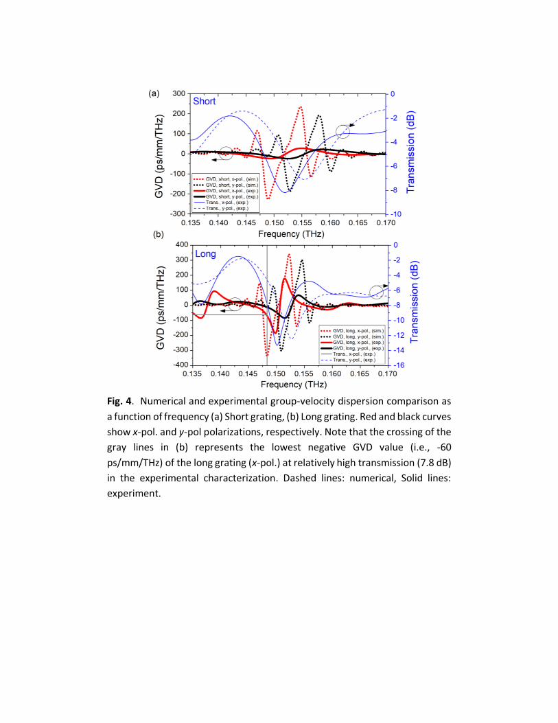
Fig. 4. Numerical and experimental group-velocity dispersion comparison as
a function of frequency (a) Short grating, (b) Long grating. Red and black curves
show x-pol. and y-pol polarizations, respectively. Note that the crossing of the
gray lines in (b) represents the lowest negative GVD value (i.e., -60
ps/mm/THz) of the long grating (x-pol.) at relatively high transmission (7.8 dB)
in the experimental characterization. Dashed lines: numerical, Solid lines:
experiment.