Embed Size (px)
Citation preview

TENDER
Up-gradation of power transformer capacity from 3.15MVA to 5MVA at 33/11KV Sub-
station at Belpada (existing 2 x 3.15 MVA+1 x1.6 MVA)
UNDER RLTAP: 2015-16
IN
Belpada Block
OF
BALANGIR DISTRICT
Cost of Tender Paper : Rs. 5,000/- + 5% VAT
Date of Sale : Dt. 12.08.2014 to Dt. 02.09.2014 (Upto 2:00 PM)
Date of Submission : 2:00 PM of Dt. 10.09.2014
Date of Opening : Dt.10.09.2014 at 5.00 PM
Bank Draft No. & Date
& Name of Bank :
Issue to :
Sd/-
Signature of Tenderer Signature of Collector
& District Magistrate, Balangir
Signature of the Tenderer Page 2 of 122
SECTION – I
INVITATION FOR BIDS (IFB)
Signature of the Tenderer Page 3 of 122
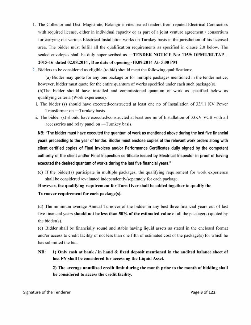
1. The Collector and Dist. Magistrate, Bolangir invites sealed tenders from reputed Electrical Contractors
with required license, either in individual capacity or as part of a joint venture agreement / consortium
for carrying out various Electrical Installation works on Turnkey basis in the jurisdiction of his licensed
area. The bidder must fulfill all the qualification requirements as specified in clause 2.0 below. The
sealed envelopes shall be duly super scribed as ―TENDER NOTICE No: 1159/ DPMU/RLTAP –
2015-16 dated 02.08.2014 , Due date of opening -10.09.2014 At- 5.00 PM
2. Bidders to be considered as eligible (to bid) should meet the following qualifications;
(a) Bidder may quote for any one package or for multiple packages mentioned in the tender notice;
however, bidder must quote for the entire quantum of works specified under each such package(s).
(b)The bidder should have installed and commissioned quantum of work as specified below as
qualifying criteria (Work experience).
i. The bidder (s) should have executed/constructed at least one no of Installation of 33/11 KV Power
Transformer on ―Turnkey basis.
ii. The bidder (s) should have executed/constructed at least one no of Installation of 33KV VCB with all
accessories and relay panel on ―Turnkey basis.
NB: “The bidder must have executed the quantum of work as mentioned above during the last five financial
years preceeding to the year of tender. Bidder must enclose copies of the relevant work orders along with
client certified copies of Final Invoices and/or Performance Certificates dully signed by the competent
authority of the client and/or Final Inspection certificate issued by Electrical Inspector in proof of having
executed the desired quantum of works during the last five financial years.”
(c) If the bidder(s) participate in multiple packages, the qualifying requirement for work experience
shall be considered /evaluated independently/separately for each package.
However, the qualifying requirement for Turn Over shall be added together to qualify the
Turnover requirement for each package(s).
(d) The minimum average Annual Turnover of the bidder in any best three financial years out of last
five financial years should not be less than 50% of the estimated value of all the package(s) quoted by
the bidder(s).
(e) Bidder shall be financially sound and stable having liquid assets as stated in the enclosed format
and/or access to credit facility of not less than one fifth of estimated cost of the package(s) for which he
has submitted the bid.
NB: 1) Only cash at bank / in hand & fixed deposit mentioned in the audited balance sheet of
last FY shall be considered for accessing the Liquid Asset.
2) The average unutilized credit limit during the month prior to the month of bidding shall
be considered to access the credit facility.
Signature of the Tenderer Page 4 of 122
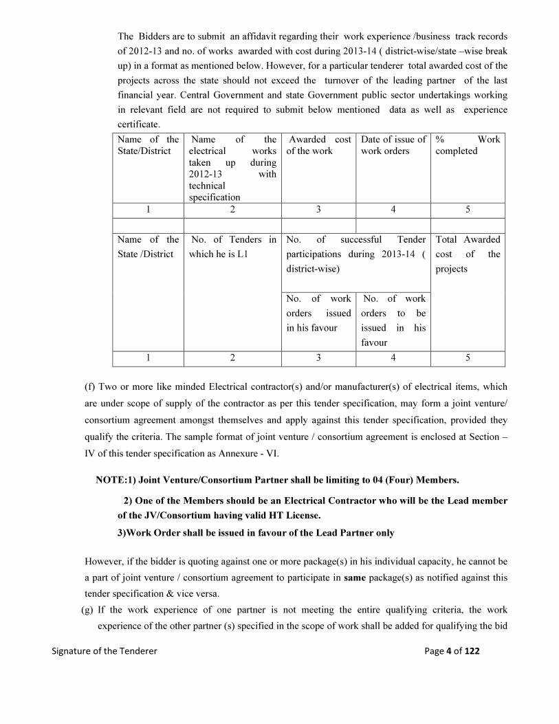
The Bidders are to submit an affidavit regarding their work experience /business track records
of 2012-13 and no. of works awarded with cost during 2013-14 ( district-wise/state –wise break
up) in a format as mentioned below. However, for a particular tenderer total awarded cost of the
projects across the state should not exceed the turnover of the leading partner of the last
financial year. Central Government and state Government public sector undertakings working
in relevant field are not required to submit below mentioned data as well as experience
certificate.
Name of the
State/District
Name of the
electrical works
taken up during
2012-13 with
technical
specification
Awarded cost
of the work
Date of issue of
work orders
% Work
completed
1 2 3 4 5
Name of the
State /District
No. of Tenders in
which he is L1
No. of successful Tender
participations during 2013-14 (
district-wise)
Total Awarded
cost of the
projects
No. of work
orders issued
in his favour
No. of work
orders to be
issued in his
favour
1 2 3 4 5
(f) Two or more like minded Electrical contractor(s) and/or manufacturer(s) of electrical items, which
are under scope of supply of the contractor as per this tender specification, may form a joint venture/
consortium agreement amongst themselves and apply against this tender specification, provided they
qualify the criteria. The sample format of joint venture / consortium agreement is enclosed at Section –
IV of this tender specification as Annexure - VI.
NOTE:1) Joint Venture/Consortium Partner shall be limiting to 04 (Four) Members.
2) One of the Members should be an Electrical Contractor who will be the Lead member
of the JV/Consortium having valid HT License.
3)Work Order shall be issued in favour of the Lead Partner only
However, if the bidder is quoting against one or more package(s) in his individual capacity, he cannot be
a part of joint venture / consortium agreement to participate in same package(s) as notified against this
tender specification & vice versa.
(g) If the work experience of one partner is not meeting the entire qualifying criteria, the work
experience of the other partner (s) specified in the scope of work shall be added for qualifying the bid
Signature of the Tenderer Page 5 of 122
in total.
Lead Partner should have minimum 50% of Turn Over & 50% of work experience and other
partner(s) together shall have balance 50% Turn over & Work experience.
(NB: 50% of the total estimated cost shall be consider for fulfilling the condition)
(i) One of the partners shall be nominated as Lead Partner and the lead partner shall be authorized to
incur liabilities and receive instructions for and on behalf of all partners of the joint venture /
consortium and entire execution of the contract including receipt of payments shall be done
exclusively through the lead partner. This authorization shall be evidenced by submitting by a
Power of Attorney signed by legally authorized signatories of all partners.
(ii) All partners of joint venture / consortium shall be liable jointly and severally for the execution of
contract in accordance with the contract terms and a copy of the agreement entered into by the joint
venture / consortium partners having such a provision shall be submitted with the Bid. A statement
to this effect shall be included in the authorization mentioned as above as well as in the Bid form
and in Contract form (in case of a successful bid).
(h) (a) In addition to above the bidder(s)/Lead Partner of the bidder(s) should submit the following
documents in part-I bid as qualifying terms.
a. Valid electrical (HT) license for electrical works.
b. EPF registration
c. PAN & TIN No.
d. Valid STC/ITC
(b) The bidder(s)/Lead Partner of the bidder(s) shall have to furnish service tax registration, ESI, Labor
license, Registration under Building & other Construction workers welfare cess within 45 days of receipt of
the order.
(i) Tenderer reserves the right to waive minor deviation, if they do not materially affect the
capacity of the bidder to perform the contract.
3.0 Bids specification document can be obtained from the office of the undersigned on payment of Rs.
5,000/- towards non-refundable cost of bid documents plus 5 % VAT (Total Rs. 5250/-) through Bank
DD drawn in favour of ―Collector and Dist Magistrate, Balangir payable at Balangir, during office
hours from 12.08.2014 to 02.09.2014 till 2 pm for each package.
4.0The tender documents can also be downloaded from the following websites : www.balangir.nic.in. In case
tender papers are downloaded from website, then the bidder has to enclose a Demand Draft, drawn on any
Scheduled bank in favour of ― Collector and Dist Magistrate, Balangir payable at Balangir, covering the cost of
bid documents as stated above in a separate envelope with suitable superscription ―Cost of Bid Documents:
Tender Notice No.: 1159 dated 02.08.2014 This envelope should accompany the Bid Documents.
Signature of the Tenderer Page 6 of 122
5.0The Bids shall be submitted and received in the office of the undersigned on all office working days up
to 2.00 PM of Date 10.09.2014. In the event the date of opening is a holiday, the next working day shall be
treated as the date of opening. .
6.0 The Bids will be opened on Dated 10.09.2014 at 5.00 PM, in the presence of the authorized
representatives of the Bidders. Bidders shall depute only one representative to attend tender opening if
they wish to be represented. The undersigned reserves the right to reject any or all tenders if the situations
so warrants.
7.0 All correspondence with regard to the above shall be made to the following address:
Sd/-
Collector and District Magistrate
Balangir
Signature of the Tenderer Page 7 of 122
SECTION – II
GENERAL CONDITIONS OF CONTRACT (GCC)
Signature of the Tenderer Page 8 of 122
1.0 GENERAL: -
Tenderer hereinafter referred to as the ―Owner is desirous of construction of various System
Improvement Works under the RLTAP Scheme 2014-15, on turnkey basis as described below: (i) Supply and commissioning of 33/11 kv Delta star ONAN cooled 5MVA Power transformer as per
specification at existing Plinth of 33/11 Kv grid S/S at Chhatamakhna.
(ii) Dismantling of existing 3.15 MVA 33/11 KV Power transformer and draining out of oil in full and
transportation of 3.15MVA transformer to Bolangir Store of WESCO complete with oil and other
accessories in good condition.
(iii) Construction of 33KV VCB foundation as per direction of Engineer In-Charge.
(iv) Supply and commissioning of 33KV outdoor type VCB with complete set (CT, PT etc) with indoor
control relay panel including pre-commissioning and post-commissioning test etc and erection of
Earthing, as per technical specification/direction of Engineer in-charge.
2.0 Scope of Work: -
2.1The scope shall include supply and installation of all materials & equipments to complete the works shall
be supplied by the Purchaser.
2.2The detailed scope of the work shall include;
i. Detailed survey of substation, line and preparation of SLD / BOQ to be done by the bidder
ii. Complete manufacture, including shop testing & supply of materials on subsequent approval of the
owner.
iii. Providing Engineering drawing, data, operational manual, etc for the Owner‘s approval;
iv. Packing and transportation from the manufacturer‘s works to the site.
v. Receipt, storage, preservation and conservation of equipment at the site.
vi. Pre-assembly, if any, erection testing and commissioning of all the equipment;
vii. Reliability tests and performance and guarantee tests on completion of commissioning;
viii. Loading, unloading and transportation as required.
ix. Erection of equipments in Sub-station including civil works.
x. Erection of lines of specified voltage.
xi. Testing, Commissioning of substations and lines / installations .
xii. Storing before erection .
xiii. Getting the substations & lines inspected by Electrical Inspector after completion of work.
Dismantling of existing electrical structures and return of these dismantled items to the Owner‘s stores.
Signature of the Tenderer Page 9 of 122
3.0 DEFINITION OF TERMS
i. The Contract ‘means the agreement entered into between the Owner and the Contractor as per the Contract
Agreement signed by the parties, including all attachments and appendices there to and all documents
incorporated by reference therein.
ii. Owner’s shall mean WESCO and shall include its legal representatives, successors and assigns.
iii. Contractor’s shall mean the Bidder whose bid will be accepted by the Owner for the award of
the Works and shall include such successful Bidder‘s legal representatives, successors and permitted
assigns.
(j) Executive Engineer or his Authorized Representative appointed for the purpose of the Contract.
(k) Specifications‘ shall mean the specifications and Bidding Document forming a part of the Contract
and such other schedules and drawings as may be mutually agreed upon.
(l) Site shall mean and include the land and other places on, into or through which the works and the
related facilities are to be erected or installed and any adjacent land, paths, street or reservoir which
may be allocated or used by the Owner or Contractor in the performance of the Contract.
(m) Inspector shall mean the Purchaser or any person nominated by the Owner from time to time, to
inspect the equipment; stores or Works under the Contract and/or the duly authorized representative
of the Owner.
(n) Notice of Award of Contracts/ „Letter of Award shall mean the official notice issued by the
Owner notifying the Contractor that his bid has been accepted.
(o) Date of Contracts shall mean the date on which notice of Award of Contract/ Letter of Award has
been issued.
(p) Performance and Guarantee Tests, shall mean all operational checks and tests required to
determine and demonstrate capacity, efficiency, and operating characteristics as specified in the
Contract Documents.
(q) The term „Final Acceptance/ „Taking Over shall mean the Owner‘s written acceptance of the
works performed under the Contract, after successful commissioning/ completion of Performance
and Guarantee Tests, as specified in the accompanying Technical Specifications or otherwise agreed
in the contract.
(r) Commercial Operation shall mean the condition of operation in which the complete equipment
covered under the Contract is officially declared by the Owner to be available for continuous
operation at different loads up to and including rated capacity. Such declaration by the Owner,
however, shall not relieve or prejudice the Contractor of any of his obligations under the Contract.
(s) Words imparting „Person shall include firms, companies, corporations and associations or bodies of
individuals, whether incorporated or not.
(t) Terms and expressions not herein defined shall have the same meaning as are assigned to them in the
Indian Sale of goods Act (1930), failing that in the Indian Contract Act (1872) and failing that in the
General Clauses Act (1897) including amendments thereof, if any.
Signature of the Tenderer Page 10 of 122
(u) In addition to the above the following definition shall also apply
a) All equipment and materials to be supplied shall also mean “Goods”
b) Constructed shall also mean erected and installed.
c) „Contract Performance Guarantee shall also mean „Contract Performance
4.0 SUBMISSION OF TENDER: -
4.1 Sealed tenders in Two parts each in duplicate, each complete in all respects in the manner hereinafter
specified are to be submitted at DPMU, Balangir-767001 on or before the date and time specified in the
notice inviting the tenders. Bids shall be submitted as per format provided in Section – III, Annexure -I.
Each copy of the bids (original and duplicate) shall be submitted in separate double sealed envelopes
superscripted on each of the covers the tender specification number and the due date of opening of the
bids on the right hand top side of the envelope. On the left top side original/ duplicate as is relevant shall
be written.
4.2 The tenders are required to be submitted in Two Parts each in separate double sealed covers.
Part - I: Superscribed as “Technical and commercial bid” shall contain EMD, Cost of Bid Documents and Techno commercial documents.
Part - II, Superscribed as “Price Bid”. The Part - II should contain only Price bid.
4.3 Fax and Telegraphic tenders shall not be accepted. 4.4 Receipt of bids/ revised bids after the cut off time and date as specified in the Tender specification shall
not be permitted and such bids shall be rejected outright. The Owner shall not be responsible for any
delay in transit in post / courier etc. in this regard.
5.0 VALIDITY:-
The offer shall be valid for a period not less than 180 days from the date of bid opening.
6.0 PRICE: -
Bidders are required to quote firm price as per the prescribed format enclosed with the tender as
BOQ/Price schedule. The quoted price shall be firm and inclusive of all taxes, duties, freight &
insurance and other levies, if any. Owner shall not be liable to pay anything extra over and above
the quoted price.

Signature of the Tenderer Page 11 of 122
7.0 RECEIPT AND OPENING OF THE BID: -
7.1 Bids in duplicate as described under clause 4.0 shall be received in the office of the Owner and shall be
opened on the scheduled date and time. The Owner‘s authorized representatives shall open bids in the
presence of Bidders‘ representatives on the date and time for opening of bids as specified in the
Invitation to Bid or in case any extension has been given thereto, on the extended bid opening date and
time notified.
7.2 Maximum one representative for each bidder shall be allowed to witness the opening of bids. The
representative must produce suitable authorization in this regard to be eligible to witness the bid opening
on behalf of the bidder. Bidders‘ representatives who are present shall sign in a register evidencing their
attendance.
7.3 The Bidders‘ names, bid prices, modifications, bid withdrawals and the presence or absence of the
requisite bid guarantee and such other details as the Owner, at its discretion, may consider appropriate
will be announced at the opening. No electronic recording devices will be permitted during bid opening.
7.4 Information relating to the examination, clarification, evaluation and comparison of Bids and
recommendations for the award of a contract shall not be disclosed to Bidders or any other persons not
officially concerned with such process. Any effort by a Bidder to influence the
Owner‘s processing of Bids or award decisions may result in the rejection of the Bidder's Bid.
8.0 EVALUATION OF BIDS & AWARD OF CONTRACT:
8.1 To assist in the examination, evaluation and comparison of Bids, the Owner may, at its discretion, ask
the Bidder for a clarification of its Bid. All responses to requests for clarification shall be in writing and
no change in the price or substance of the Bid shall be sought, offered or permitted.
8.2 Owner will examine the Bids to determine whether they are complete, whether any computational errors
have been made, whether required sureties have been furnished, whether the documents have been
properly signed, and whether the Bids are generally in order.
8.3 Arithmetical errors will be rectified on the following basis. If there is a discrepancy between the unit
price and the total price per item that is obtained by multiplying the unit price and quantity, the unit
price shall prevail and the total price per item will be corrected. If there is a discrepancy between the
Total Amount and the sum of the total price per item, the sum of the total price per item shall prevail and
the Total Amount will be corrected.
8.4 Prior to the detailed evaluation, Owner will determine the substantial responsiveness of each Bid to the
Bidding Documents including production capability and acceptable quality of the Goods offered. A
substantially responsive Bid is one, which confirms to all the terms and conditions of the Bidding

Signature of the Tenderer Page 12 of 122
Documents without material deviation.
8.5 The Owner‘s evaluation of a Bid will take into account, in addition to the Bid price, the following
factors, in the manner and to the extent indicated in this Clause:
(a) Work Schedule
(b) Deviations from Bidding Documents 8.6 The Owner will award the Contract to the successful Bidder whose Bid has been determined to be the
lowest - evaluated responsive Bid. When the lowest bidders is not ready and/or capable to undertake the
entire work envisaged, then the Owner may explore the possibility of the execution of works through
other bidders if they are willing to execute at L1 rate. Such exploration shall be carried out in a
sequential order starting with L2 bidder then with L3 bidder and so on.
a. In case of omission of any item in the price bid or the price for the item has not been quoted by the
firm, then zero cost shall be loaded to the bid and the contract shall be awarded with zero cost that
means the firm will have to bear the cost of that item entirely as the item price shall be considered
as inclusive anywhere in other items. The bidder shall have to give an undertaking to the effect that
prices for any item not quoted shall be treated as free supply or to be done free of cost.
9.0EARNEST MONEY DEPOSIT (EMD):-
9.1 The Tender must be accompanied by Earnest Money Deposit as described in the Tender Notice in shape
of Bank Guarantee issued by a Scheduled Bank (valid for 30 days beyond the validity of bid) only and
en-cashable at Balangir or in shape of Demand Draft drawn on any scheduled bank in favour of
―Collector and Dist Magistrate, Balangir payable at Balangir. Bids without EMD deposit will be
rejected out rightly. The Bank Guarantee for EMD shall be strictly as per the format [Annexure –
XV(A)] prescribed by the Owner. In case of any deficiency such as the ownership of the security bond
(other than the issuing bank), deviation from the approved format, absence of signature of witness etc.
found in the EMD
Bank Guarantee, the same shall be liable for rejection upfront.
NB: 1) The validity of EMD BG shall be minimum for 30 days over and above the validity of the
tender/bid (180 days) i.e., 210 days from the date of opening of the tender.
2) In case of Joint Venture / Consortium, EMD in shape of BG/DD shall be provided by the Lead
Partner.
9.2 No adjustment of any previous deposit or any amount payable from Purchaser shall be entertained for
EMD. EMD amount so submitted shall not carry any interest payable to the bidder.
9.3 The Earnest Money so deposited shall be forfeited:
(a) If the Bidder: withdraws its bid during the period of bid validity specified by the Bidder in the Bid
Form; or in the case of a successful Bidder, if the Bidder fails: to accept the LOA/Work order within the
period specified in the LOA/Work order. to furnish the required Contract Performance Bank Guarantee.
Signature of the Tenderer Page 13 of 122
9.4 The EMD of unsuccessful bidders shall be returned within 30 days from the date of finalization of the
order.
10.0 OWNER’S RIGHT TO VARY QUANTITIES AT TIME OF AWARD:
While placing orders and / or during execution of contract, Owner reserve the right to increase or
decrease the quantity of goods and services specified in the Schedule of Requirement up to 20% of the
tender quantity without any change in unit price or other terms and conditions.
11. INSPECTION AND TESTING:- 11.0 All the materials shall be inspected by the Executive Engineer or any authorized representative of the
Executive Engineer or jointly by the Executive Engineer or any authorized representative at the
Contractor‘s or its Sub-Vendors manufacturing works. They shall give the advance notice in writing
about the place of Inspection and or testing at least 15 days before the schedule date on which the
materials will be ready for Inspection & Testing.
11.2 The Executive Engineer shall be entitled at all reasonable times during manufacture / installation to
inspect examine and test the materials at the contractor‘s premises / erection site about workmanship of
the materials to be supplied under this contract. If the said materials are being manufactured in other
premises, the contractor shall provide unhindered clearance, giving full rights to the purchaser to
inspect, examine and test as if the materials were being manufactured in his premises. Such inspection /
examination and testing shall not relieve the contractor of his obligations to execute the contract by letter
and spirit. The contractor shall give the purchaser advance notice in writing of the Date and the Place at
which the materials will be ready for testing.
12.0 COMPLETION AND COMPLETENESS OF THE EQUIPMENT:-
12.1 Time being the essence of the contract; the work shall be completed within as follows from the date of
issue of work order.
i) commissioning of 33/11 kv Delta star ONAN cooled 5MVA Power transformer as per specification at existing Plinth of 33/11 Kv grid S/S – 6 months
ii) Construction of 33KV VCB foundation and commissioning of 33KV outdoor type VCB with
complete set (CT, PT etc) with indoor control relay panel along with earthing – 3 months
Signature of the Tenderer Page 14 of 122
12.2 The work shall be treated as complete when the entire work as per scope of the order shall be complete
in all respects with all mountings, fixtures and standard accessories which are normally supplied even
though not specifically detailed in the specification. No extra payment shall be payable for such
mounting, fittings, fixtures and accessories which are needed for safe operations of the equipment as
required by applicable code of the country though this might not have included in the contract.
12.3 All similar components and/or parts of similar equipment supplied shall be inter-changeable with one
another. Various equipments supplied under this contract shall be subject to Owner‘s approval.
12.4 Executive Engineer however reserves the right to re-schedule the completion period, if required.
13.0 REJECTION OF MATERIALS: -
In the event of the materials supplied by the contractor and/or the installation works are found to be
defective in quality and the workmanship is poor or otherwise not in conformity with the requirements
of the contract specification as per section-IV (Technical specification), Owner/ Executive Engineer
shall reject such materials / services and ask the contractor in writing to replace / rectify the defects. The
contractor on receipt of such notification shall rectify or replace the defective materials and/or re-install
the work already executed, free of cost to the Owner. If the contactor fails to do so the Owner/ Executive
Engineer may at his option take the following actions which could be on concurrent basis.
Replace or rectify such defective materials and recover the extra cost so involved plus 25% from the Contractor. Terminate the contract for balance supply and erection with enforcement of penalty as per contract. Acquire the defective materials at reduced price considered acceptable under the circumstances.
Forfeit the Contract Performance Bank Guarantee.
14.0 DEVIATION FROM SPECIFICATION: -
The bidders are requested to study the specification and the attached drawings thoroughly before
tendering so that if they make any deviations, the same are prominently brought on a separate sheet
under the headings ―Deviations as per formats provided under Section III, Annexure – VII & VIII. All
such deviations to the technical & commercial terms of the specification shall be indicated in a separate
list as indicated above. In absence of such deviation schedule, it will be presumed that the bidder
has accepted all the conditions stipulated in the tender specification, not withstanding any
deviations mentioned elsewhere in the Bid. However the acceptance of deviation is not binding on the
Owner.

Signature of the Tenderer Page 15 of 122
15.0 CONTRACTOR TO INFORM HIMSELF FULLY: -
The contractor shall examine the instructions, general conditions of the contract, specifications and the
schedule of quantity and delivery to satisfy himself as to all the terms and conditions and circumstances
affecting the contract price. He shall quote prices according to his own judgment and shall understand
that no additional cost except as quoted shall only be considered.
16.0 PATENT RIGHT: -
The contractor shall indemnify the Owner against all claims, actions, suits and proceedings for the
alleged infringement any patent design or copy right protected either in country of origin or in India by
the use of any equipment supplied by the contractor but such indemnity shall not cover any use of the
equipment other than for the purpose indicated by or reasonable to be informed from the specification.
17.0 GUARANTEE PERIOD: -
i) The materials to be supplied by the contractor as well as installation of the same (i.e., entire work
including materials supplied by contractor) shall be guaranteed for satisfactory operation against defects in
design and workmanship for a period of 24 months from the date of handing over the completed
installations after commercial operation at required voltage level.
ii) The above guarantee certificate shall be furnished in triplicate to the Executive Engineer for his approval.
Any defects noticed during the above period should be rectified by the Contractor free of cost to the Utility
provided such defects are due to faulty design, bad workmanship or bad materials used on receipt of written
notice from the Executive Engineer. The Contractor as notified by the Project Manager shall rectify any such
defects within one month failing which the Owner/ Executive Engineer will set right the defects through
other agency and recover the cost so incurred either from any pending Invoices or Bank Guarantee.
18.0 PENALTY FOR DELAY IN COMPLETION OF CONTRACT: -
i) If the contractor fails to complete the works by the scheduled period or any extension granted
thereby, the contractor shall be liable for payment of penalty amounting to 0.5% (half percent) of the
contract price per week of un-finished works subject to the maximum of 5% (fivepercent) of the total
contract price and subject to force majeure conditions.
ii) Penalty amount can be realized from the proceeds of the Contract Performance Bank Guarantee, if
Signature of the Tenderer Page 16 of 122
the situation so warrants.
iii) Extension of delivery period could be with / without levy of penalty with the discretion of
owner/ Executive Engineer.
19.RIGHT OF WAY:
Right of way issues, if any, arising during execution of the works shall have no liability on the Owner.
These issues shall be settled at the sole discretion of the Contractor. The Executive Engineer shall
however extend all possible help to the Contractor including discussion with the local authorities for
early resolution of these issues.
20.0 CONTRACTOR’S DEFAULT:
i) If the Contractor neglects to execute the works with due diligence and expedition or refuses or
neglects to comply with any reasonable order given to him, in writing by the Engineer in charge
with the works or contravenes the provisions or the contract, the Owner/ Executive Engineer may
give notice in writing to the Contractor to make good the failure, neglect or contravention
complained of. If the Contractor fail to comply with the notice within thirty (30) days from the date
of serving the notice, the Owner/ Executive Engineer shall be at liberty to employ other workmen
and forthwith execute such part of the works as the contractor may have neglected to do or if the
Owner/ Executive Engineer thinks fit, without prejudice to any other right, he may have under the
Contract to take the work wholly or in part out of the Contractor‘s hands and re-contract with any
other person or persons to complete the works or any part thereof and in that event the Owner/
Executive Engineer shall have free use of all Contractor‘s equipment that may have been at the time
on the Site in connection with the works without being responsible to the Contractor for fair wear
and tear thereof and to the exclusion of any right of the Contractor over the same, and the Owner /
Executive Engineer shall be entitled to retain and apply any balance which may otherwise be due on
the Contract by him to the Contractor, or such part thereof as may be necessary, to the payment of
the cost of executing the said part of works or of completing the works as the case may be. If the
cost of completing of works or executing part thereof as aforesaid shall exceed the balance due to
the Contractor, the Contractor shall pay such excess. Such payment of excess amount shall be
independent of the liquidated damages for delay which the Contractor shall have to pay if the
completion of works is delayed.
ii) In addition, such action by the Owner/ Executive Engineer as aforesaid shall not relieve the
Contractor of his liability to pay liquidated damages for delay in completion of works.
Signature of the Tenderer Page 17 of 122
iii) Such action by the Owner/ Executive Engineer as aforesaid the termination of the Contract
under this clause shall not entitle the Contractor to reduce the value of the Contract
Performance Guarantee nor the time thereof. The Contract Performance Guarantee shall be
valid for the full value and for the full period of the Contract including guarantee.
20.1 TERMINATION OF CONTRACT ON OWNERS INITIATIVE:
a. Owner reserves the right to terminate the Contract either in part or in full due to reasons
other than those mentioned under clause entitled Contractor‘s Default‘. The Owner shall
in such an event give fifteen (15) days notice in writing to the Contractor of his decision
to do so.
b. The Contractor upon receipt of such notice shall discontinue the work on the date and to
the extent specified in the notice, make all reasonable efforts to obtain cancellation of all
orders and Contracts to the extent they related to the work terminated and terms
satisfactory or the Owner, stop all further sub-contracting or purchasing activity related
to the work terminated, and assist Owner in maintenance, protection, and disposition of
the works acquired under the Contract by the Purchaser. In the event of such a
termination the Contractor shall be paid compensation, equitable and reasonable,
dictated by the circumstance prevalent at the time of termination to be determined by
the arbitrator without stopping the work but to carry out the left over work to other
agency.
c. If the Contractor is an individual or a proprietary concern and the individual or the proprietor
dies and if the Contractor is a partnership concern and one of the partners dies then unless the Owner is
satisfied that the legal representatives of the individual Contractor or of the proprietor of the propriety
concern and in the case of partnership, the surviving partners, are capable of carrying out and in the case
of partnership, the surviving partners, are capable of carrying out and completing the Contract the
Owner shall be entitled to cancel the Contract as to its uncompleted part without being in any way liable
to payment of any compensation to the estate of deceased Contractor and /or to the surviving partners of
the Contractor‘s firm on account of the cancellation of the contract. The decision of the Owner that the
legal representatives of the
deceased Contractor or surviving partners of the Contractor‘s firm cannot carry out and
complete the contract shall be final and binding on the parties. In the event of such cancellation the
Owner shall not hold the estate of the deceased Contractor and/ or the surviving partners of the
Contractor‘s firm liable to damages for not completing the Contract.

Signature of the Tenderer Page 18 of 122
20.2 FORCE MAJEURE: -
The Contractor shall not be liable for any penalty for delay or for failure to perform the contract for
reasons of Force Majeure such as ―acts of God, acts of the Public enemy, acts of Govt.,
Fires, Flood, Epidemics, Quarantine restrictions, Strikes, Freight Embargos and provided that the
Contractor shall within ten (10) days from the beginning of such delay notify the Owner in writing of the
cause of delay. The Owner shall verify the facts and grant extension as facts justify.
20.3 EXTENSION OF TIME: -
If the delivery of the equipments / materials is delayed due to reasons beyond the control of the
Contractor, the Contractor shall immediately inform within 3 days to the Owner in writing of his claim
for an extension of time. The Owner on receipt of such notice may agree to extend the contract period as
may be reasonable but without prejudice to other terms & conditions of the contract.
20.4 SAFETY PRECAUTIONS:-
The agency shall observe all applicable regulations regarding safety at the Site. Any compensation due
on account of accident at site shall be to the contractor‘s account.
20.5 STORE:-
Storing of materials from supply to erection shall be arranged by the contractor at his own cost. No
compensation shall be made by the Owner for any damage or loss of materials during storing, transit
transportation and at the time of erection.
20.6 INSURANCE: -
Contractor shall arrange adequate Transit-cum-storage-cum-erection policy and shall submit the copy of
the same to the Owner. The policy shall initially remain valid for a period of sixty days over & above of
the contractual guarantee period and shall be extended as required till handing
over. Contractor shall be responsible for lodging of claim with the insurer as well as for all required
follow up with the insurer for settlement of claim in case of loss/damage/theft of material during
transit/storage/erection till the completed works is handed over to the Purchaser and is accepted by the
authorized representative of the Purchaser in writing.
Contractor shall also arrange adequate cover for his employees / labourer’s engaged in the works as well
as arrange third party insurance cover to indemnify any possible damages to public at large not
connected with the works process. Any claim(s) pertaining to this shall be the responsibility of the
Contractor. The contractor shall undertake free replacement of the materials damaged or lost during
transit, which will be intimated by the Consignee within 30 days of receipt of the materials at Owner‘s
Signature of the Tenderer Page 19 of 122
stores.
20.7 PROJECT MANAGER & ENGINEER IN CHARGE:-
The Executive Engineer of concerned division shall be the Engineer in charge for the Project.
20.8 CONTRACT PERFORMANCE BANK GUARANTEE:-
i) Within 15 days of issue of the Work Order or Letter of Award, whichever is earlier, the
Contractor shall submit Contract Performance Bank Guarantee issued by a scheduled Bank,
in favour of the Owner, covering 10% of the total value of the work order,
NB: In case of Joint Venture/Consortium, Lead Member shall submit Contract Performance BG
covering 10% of Order value & every member of the Consortium/JV shall submit additional
Performance BG covering 1% of the value of the order.
ii)The said Bank Guarantee shall be prepared in the prescribed Performa as attached in
Section IV, Annexure - III. The Bank Guarantee furnished shall be executed on Non-judicial
Stamp paper worth of Rs 100/- (Rupees Hundred only), purchased in the name of the issuing
bank, as per the prevalent rules. The Bank Guarantee so provided shall be en-cashable
on the Balangir branch of the issuing Bank.
iii) The Contract Performance Bank Guarantee shall remain valid for a period not less than 90 daysover and
above the guarantee period, basing on stipulated completion period in the W.O. Page towards security and
acceptance thereof, failing which the work orders (W.O) will be liable for cancellation without any further notice
with forfeiture of E.M.D.
iv) No interest shall be allowed by the Owner on the above Performance Security Deposit.
20.9 TERMS OF PAYMENT:
i)80% (Eighty percent) of contract price along with taxes and duties shall be paid progressively for each
completed items of work certified by the Jr. Manager (in charge of concerned Section) & Engineer in charge
against each calendar month by first week of the succeeding months along with utilization certificate. No
payment shall be released if the accounts for utilization of materials unless follow with proper certification
by the concerned Jr. Manager (in charge of concerned Section) & Engineer in charge.
ii) Balance 20% (twenty percent) of contract price shall be paid after completion of all works, envisaged
under this package including any additions and alterations, testing & commissioning, return of dismantled
materials/ un-used free supply material, taking over certificate and entire stretch is fully ready for commercial
operation. The payments shall be subjected to clearance from electrical inspectorate.
20.10 PAYING OFFICER:
Owner shall notify the paying officer for the project.
Signature of the Tenderer Page 20 of 122
21.0 OWNER’S RIGHTS: -
The Owner reserves the right to accept any bid or reject any or all bids or cancel / withdraw invitation of
bid or to vary the quantity for placement of order without assigning any reason to such decision. Such
decision by the Owner shall bear no liability.
22.0 DISPUTE RESOLUTION AND JURISDICTION: -
(a) Any disputes arising out of this contract shall be referred to the Collector and DM, Balangir who
shall decide the case as sole Arbitrator.
(b) For the purpose of dispute resolution, this agreement shall be governed by the provision of
Arbitration and Conciliation Act, 1996.
(c) All disputes shall be subjected to exclusive jurisdiction of the Courts at Balangir and the writ
jurisdiction of Hon‘ble High Court of Odisha at Cuttack.
23.0 TRANSFER AND SUB-LETTING
The Contractor shall not sublet, transfer, assign or otherwise part with the Contract or any part thereof,
either directly or indirectly, without prior written permission of the Owner.
24.0 SUBMITTALS REQUIRED AFTER AWARD OF CONTRACT
i) Within 30 days of the effective date of contract the contractor shall provide three copies of an
outline program of production, inspection, testing, delivery, survey, erection, pre-commissioning and
commissioning in chart form to the Executive Engineer. Included in the program will be the detailed
schedule of drawing to be submitted.
ii) The periodic progress report as required by the Owner shall be submitted by the contractor as
per the format prescribed by the Engineer in Charge.
25.0 DRAWINGS
Within 15 days of contract commencement the contractor shall submit, for approval by the Executive
Engineer, a schedule of the drawings to be produced. The schedule shall also provide a program of
drawing submission, for approval by the Engineer in Charge. All drawings and design should be
submitted to Executive Engineer within the period specified above.
26.0 TAKING OVER
i) Upon successful completion of all the tests to be performed at site on equipment / materials
supplied, erected and commissioned by the contractor, the Junior Manager shall issue to the
contractor a taking over certificate as a proof of the final acceptance of the equipment / materials on
a written request within 10 days of commercial operation. Such certificate shall not be un-reasonably

Signature of the Tenderer Page 21 of 122
withheld nor will the engineer delay the issuance thereof on account of minor omission or defects,
which do not affect the commercial operation and / or cause any serious to the equipment/material.
The conditional Taking over Certificate can be issued if any minor omission or defects pointed by
the Engineer-in-Charge/Electrical Inspector. The Contractor should rectify those defects within a
month of conditional T.O.C failing which Owner will rectify those by replacing those materials or
engaging other agencies. The amount so involved will be fully recovered from the Contractor‘s bill.
Such certificate shall, however, not relieve the contractor of any of his obligations which otherwise
survive by the terms & conditions of the contract after issuance of such certificate.
ii) For the satisfaction of Owner about quality, the Owner shall have unreserved right for
arrangement of testing of equipment/ materials and the complete system independently by self or any
other agency chosen by the Owner. The contractor is expected to agree and extend necessary help
during such test if necessary.
27.0 LATENT DEFECT WARRANTY
i) The period of latent defect warranty in terms of this bidding documents, shall be limited to five
(05) years from the date of completion of Guarantee period.
28.0 EMBOSSING / PUNCHING / CASTING / PAINTING
i) The all equipments and materials supplied /erected under the RLTAP Programmed shall bear
distinct mark of ―Name of the Purchaser, RLTAP, PO Order No. & Date by a way of embossing /
punching / casting / painting etc. This should be clearly visible to naked eye.
29.0 INDEMNIFY
18.1 The Contractor, its successor and assignee shall indemnify the Owner, its successor and
assignee from all current & future liabilities that may arise out of Turn Key Contract(s) entered
into between the Owner & the Contractor under this RLTAP Programme.

Signature of the Tenderer Page 22 of 122
SECTION - III
COMMERCIAL BID

Signature of the Tenderer Page 23 of 122
ANNEXURE – I BID PROPOSAL LETTER
Electrical Installation of Works under WESCO
Bidder‘s Name and Address: (in case of JV/Consortium, Name of JV/Consortium) Bid Proposal Reference: Person to be contacted: Designation: Telephone No. : E-mail: Fax No. :
To, The Collector &District Magistrate
Balangir, Odisha Dear Sir, We the undersigned bidder have read and examined the detailed specification and bidding documents for
execution of various electrical installations works and do herewith submit our bid for the following packages:
Sl. Name of the Name of the Estimated Cost
No. Owner Package (Rs. in Cr.)
We declare the following:
1.0 PRICES AND VALIDITY: 1.1 All the prices and price components stated in our bid proposal are firm and not subject to any price
adjustment, in line with the bidding documents. All the prices and other terms and conditions of this
proposal are valid for a period of 180 days from the date of opening of the bids. We further declare

Signature of the Tenderer Page 24 of 122
that prices stated in our proposal are in accordance with ―Instructions to Bidders of bidding
documents. 1.2 We do hereby confirm that our bid prices as quoted in attached Schedules include all import duties and
levies including license fees lawfully payable by us on imported items and other taxes, duties and levies
applicable on bought – out components, materials, equipment and other items and confirm that any such
taxes, duties and levies additionally payable shall be to our account.
1.3 We confirm that the Sales tax on Works Contract, Turnover Tax or any other similar taxes under the
Sales Tax Act, as applicable, are included in our quoted bid price and there shall not be any liability on
this account to the Purchasers. We understand that Owner shall, deduct such taxes at source as per the
rules and issue TDS Certificate to us.
1.4 We confirm that, in our Bid Price, we have considered service tax in line with lawful prevalent practice.
1.5 Price components of various items are indicated in the B.O.Q. for the respective works.
1.6 We further declare that while quoting the price, the due credit under MODVAT scheme, re-christened as
CENVAT scheme, as per relevant Government policies wherever applicable, have been taken into
account.
1.7 We, having studied the bidding document in three volumes relating to taxes & duties and hereby, declare
that if any income tax, charge on income tax or any other corporate tax is attracted under the law, we
agree to pay the same.
1.8 We are aware that the Price schedules do not generally give a full description of the supplies to be made
and work to be performed under each item and we shall be deemed to have read the Technical
Specifications and other bidding documents and drawings to ascertain the full scope of work included in
each item while filling in the related and prices. We agree that the entered rates and prices shall be
deemed to include the full scope as aforesaid, including overheads and profits.
1.9 We understand that in the price schedule, if there is discrepancy between the unit price and total price,
the same shall be corrected as per relevant provisions.
1.10 We declare that prices for items left blank in the schedules will be deemed to have been included in other
items. The TOTAL for each schedule and the TOTAL of Grand summary shall be deemed to be the total
price for executing the facilities and sections thereof in complete accordance with the contract, whether
or not each item has been priced. 2.0 CONSTRUCTION OF THE CONTRACT 2.1 We declare that we are making the offer on the basis of indivisible supply-cum-Erection contract on a
single source responsibility basis.

Signature of the Tenderer Page 25 of 122
3.0 BID SECURITY (EMD)
We are enclosing Bank Draft / Bank Guarantee No. Dt;- amounting to
Rs.--------------------- (Rupees only) issued by
Bank --------------------------- branch, payable at Balangir towards Bid Security against
our above Bid. The Bid Security amount has been computed by adding the Estimated
Cost of the package nos ------------------- for which we are submitting our bid.
4.0 EQUIPMENT PERFORMANCE GURANTEE
We declare that the ratings and performance figures of the equipment to be furnished and erected by us
are guaranteed. The Guaranteed particulars of different equipments are enclosed along with our bid.
5.0 BID PRICING
We further declare that the prices stated in our proposal are in accordance with your Instruction of
Bidders of Conditions of Contract, Volume-1 of the bid documents.
6.0 PRICE ADJUSTMENT
We declare that all the prices and price components stated in our offer are on FIRM price basis. 7.0 QUALIFICATION
We confirm having submitted the Qualification Data in original plus one copy, as required by you
under clause 6.0 Invitation for Bids‘. Further we have filled in the
Information for qualification requirements. In case you require any further
Information in this regard, we agree to furnished the same in time .
8.0 DEVIATIONS
8.1 We declare that the contract shall be executed strictly in accordance with the specifications and
documents except for the variations and deviations all of which have been detailed out exhaustively in
the following schedules, irrespective of whatever has been stated to the contrary anywhere else in our
proposal.
a) Commercial Deviations Schedule
b) Cost of withdrawal of Deviations on Critical
c) Technical Deviation Schedule
Signature of the Tenderer Page 26 of 122
8.2 We confirm that specified stipulation of following critical clauses is acceptable to us and no
deviations/exceptions are taken on any account whatsoever in the following clauses:
(a) Payment Terms :
(b) Bid Guarantee :
(c) Contract Performance Guarantee :
(d) Liquidated Damages for delay :
(e) Prices and Price Adjustment :
(f) Guarantee / Warrantees :
8.3 Further, we agree that the additional conditions, deviations, if any, found in our bid proposal documents
other than those stated in attached Deviation Schedules, save that pertaining to any rebates offered, shall
not be given effect to.
9.0 ADDITIONAL INFORMATION
We have included with this proposal additional information listed. We further confirm that such
additional information does not imply any additional deviation beyond those covered in appropriate
schedules and in case of any contradiction between these additional information and other provisions of
Bid, the latter prevail. 10.0 GURANTEE DECLARATION
We guarantee that the equipment offered shall meet the rating and performance requirements stipulated
in this specification. The Guarantee Declaration which shall attract levy of liquidated damages
for non-performance is indicated in the relevant
schedule.
11.0 WORK SCHEDULE
If this proposal is accepted by you, we agree to submit engineering data, provide services and complete
the entire work from time to time, in accordance with schedule indicated in the proposal. We fully
understand that the time schedule stipulated in this proposal is the essence of the contract, if awarded.
The completion schedule of the various major key phases of the work is indicated in the designated
schedule.
12.0 CONTRACT PERFORMANCE GUARANTEE
We further agree that if our Bid is accepted we shall provide an irrevocable Bank guarantee towards
Contract Performance Guarantee, of value equivalent to ten percent (10%) of the Contract Price initially
valid up to the end of ninety (90) days after the end of the contract warranty period in the form of Bank
Guarantee in your favour within 15(fifteen) days from the date of Notice of Award of Contract‘ /Work
Signature of the Tenderer Page 27 of 122
Order.
13.0 CHECK LIST
We have included a check list duly filled in Schedule. We understand that only this check list,
commercial and technical deviation will be read out during the part-I bid opening before the bidders
present. For Joint Venture/consortium only) We, the Partners of joint venture/ consortium submitting
their Bid, do agree and confirm that in case of Award of the Contract on the joint venture, we shall be
jointly and severally responsible for the execution of the contract in accordance with contract terms and
conditions.
We, hereby declare that only the persons or firms interested in this proposal as principals are named herein and
that no other persons or firms other that those mentioned herein have any interest in this proposal or in the
contract to be entered into if we are awarded the contract, and that this proposal is made without any connection
with any other person, firm or party likewise submitting a proposal and that this proposal is in all respect for and
in good faith, without collusion or fraud.
Dated this ………………………..day of ………………………………20…..
Thanking you, Yours faithfully,
(Signature of the Authorized Signatory) Name …………………………… Designation …………………………….. Seal of the company……….. (To be signed by lead partner in case of Joint Venture) Signature of other partner (s) in case of Joint Venture)
Name …………………
Designation …………………..
Date : ………………………….
Place :
(Written power of Attorney of all signatories of the bid to commit the Bidder must be enclosed with the
Bid. In case of joint venture, the written Power of Attorney of all signatories from respective partners
must be enclosed with the Bid. .
Signature of the Tenderer Page 28 of 122
ANNEXURE – II
DECLARATION FORM To, The Collector &District Magistrate.
Balangir, Odisha Sir, Having examined the above specifications together with the Tender terms and conditions referred
to therein
1 – I / We the undersigned do hereby offer to execute the contract covered there on in complete
shape in all respects as per the rules entered in the attached contract schedule of prices in the
tender.
2 – I / We do hereby under take to have executed the contract within the time specified in the
tender.
3 – I / We do hereby guarantee the technical particulars given in the tender supported with
necessary reports from concerned authorities.
4 – I / We do hereby certify to have purchased a copy of the tender specifications by remitting
Cash / Demand draft & this has been duly acknowledged by you in your letter No…………Dt…………
5 – I / We do hereby agree to furnish the composite Bank Guarantee in the manner specified /
acceptable by OWNER & for the sum as applicable to me / us as per clause No.29 of GCC of this
specification within fifteen days of issue of Letter of intent / Work Order, in the event of Work
order being decided in my / us favour , failing which I / We clearly understand that the said LOI /
W.O. shall be liable to be withdrawn by the Owner. Signed this…………….Day of……………………20…
Yours faithfully
(Signature of Bidder with Seal of Company)
Signature of the Tenderer Page 29 of 122
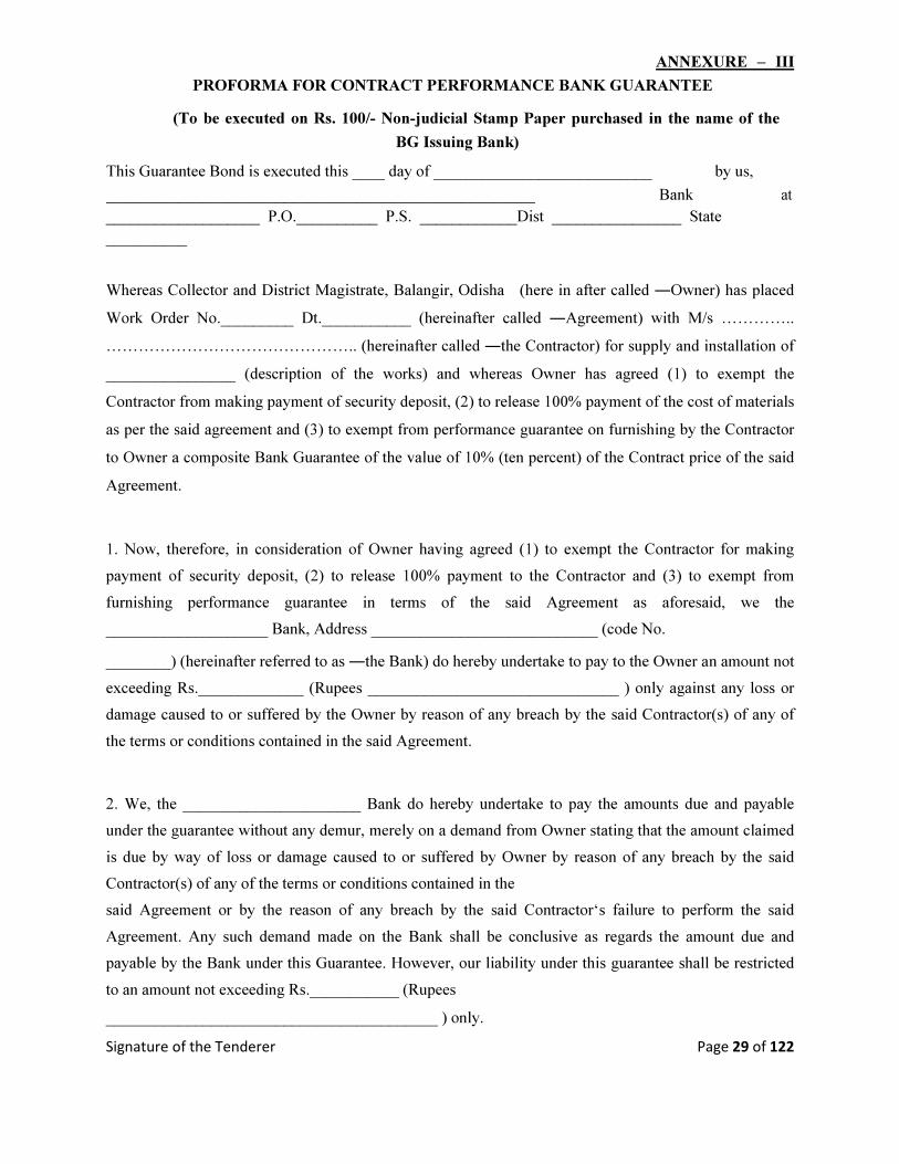
ANNEXURE – III
PROFORMA FOR CONTRACT PERFORMANCE BANK GUARANTEE
(To be executed on Rs. 100/- Non-judicial Stamp Paper purchased in the name of the
BG Issuing Bank) This Guarantee Bond is executed this ____ day of ___________________________ by us,
_____________________________________________________ Bank at ___________________ P.O.__________ P.S. ____________Dist ________________ State __________
Whereas Collector and District Magistrate, Balangir, Odisha (here in after called ―Owner) has placed
Work Order No._________ Dt.___________ (hereinafter called ―Agreement) with M/s …………..
……………………………………….. (hereinafter called ―the Contractor) for supply and installation of
________________ (description of the works) and whereas Owner has agreed (1) to exempt the
Contractor from making payment of security deposit, (2) to release 100% payment of the cost of materials
as per the said agreement and (3) to exempt from performance guarantee on furnishing by the Contractor
to Owner a composite Bank Guarantee of the value of 10% (ten percent) of the Contract price of the said
Agreement.
1. Now, therefore, in consideration of Owner having agreed (1) to exempt the Contractor for making
payment of security deposit, (2) to release 100% payment to the Contractor and (3) to exempt from
furnishing performance guarantee in terms of the said Agreement as aforesaid, we the
____________________ Bank, Address ____________________________ (code No. ________) (hereinafter referred to as ―the Bank) do hereby undertake to pay to the Owner an amount not
exceeding Rs._____________ (Rupees _______________________________ ) only against any loss or
damage caused to or suffered by the Owner by reason of any breach by the said Contractor(s) of any of
the terms or conditions contained in the said Agreement.
2. We, the ______________________ Bank do hereby undertake to pay the amounts due and payable
under the guarantee without any demur, merely on a demand from Owner stating that the amount claimed
is due by way of loss or damage caused to or suffered by Owner by reason of any breach by the said
Contractor(s) of any of the terms or conditions contained in the
said Agreement or by the reason of any breach by the said Contractor‘s failure to perform the said
Agreement. Any such demand made on the Bank shall be conclusive as regards the amount due and
payable by the Bank under this Guarantee. However, our liability under this guarantee shall be restricted
to an amount not exceeding Rs.___________ (Rupees _________________________________________ ) only.

Signature of the Tenderer Page 30 of 122
3. We, the ________________________ Bank also undertake to pay to Owner any money so
demanded not withstanding any dispute or dispute raised by the Contractor(s) in any suit or proceeding
instituted/ pending before any court or Tribunal relating thereto our liability under this Agreement being
absolute and irrevocable. The payment so made by us under this bond shall be valid discharge of our
liability for payment there under and the Contractor(s) shall have no claim against us for making such
payment.
4. We, the _________________________ Bank further agree that the guarantee herein contain shall
remain in full force and effect during the period that would be taken for the performance of the said
Agreement and it shall continue to remain in force endorsable till all the dues of Owner under by virtue of
the said Agreement have been fully paid and its claim satisfied or discharged or till Purchaser certifies
that the terms and conditions of the said Agreement have been fully and properly carried out by the said
Contractor(s) and accordingly discharge this guarantee and will not be revoked by us during the validity
of the guarantee period.
5. We, the _________________________ Bank further agree that Owner shall have the fullest liberty
without our consent and without affecting in any manner our obligations hereunder to vary any of the
terms and conditions of the said Agreement or to extend time of performance by the said Contractor(s)
and we shall not be relieved from our liability by reason of any such variation or extension being granted
to the said Contractor(s) or for any forbearance act or
omission on part of Owner or any indulgence by Owner to the said Contractor(s) or by any such matter or
thing whatsoever which under the law relating to sureties would but for this provisions have effect of so
relieving us. 6. The Guarantee will not be discharged due to change in the name, style and constitution of the
Bank and or Contractor(s).
7. We, the _________________________ Bank lastly undertake not to revoke this Guarantee during
its currency except with the previous consent of the Owner in writing.
Dated ___________ the __________ day of Two thousand _________ . Notwithstanding anything contained herein above.
Our liability under this Bank Guarantee shall not exceed Rs.______________ (Rupees _______ ____________________________________________________________________ ) only. The Bank Guarantee shall be valid up to _____________________ only.
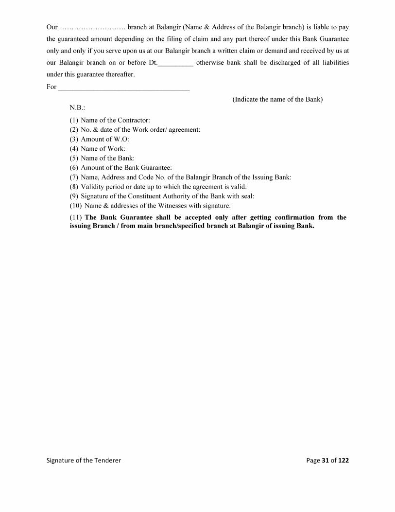
Signature of the Tenderer Page 31 of 122
Our ………………………. branch at Balangir (Name & Address of the Balangir branch) is liable to pay
the guaranteed amount depending on the filing of claim and any part thereof under this Bank Guarantee
only and only if you serve upon us at our Balangir branch a written claim or demand and received by us at
our Balangir branch on or before Dt.__________ otherwise bank shall be discharged of all liabilities
under this guarantee thereafter. For _____________________________________
(Indicate the name of the Bank) N.B.:
(1) Name of the Contractor: (2) No. & date of the Work order/ agreement: (3) Amount of W.O: (4) Name of Work: (5) Name of the Bank: (6) Amount of the Bank Guarantee: (7) Name, Address and Code No. of the Balangir Branch of the Issuing Bank: (8) Validity period or date up to which the agreement is valid: (9) Signature of the Constituent Authority of the Bank with seal: (10) Name & addresses of the Witnesses with signature:
(11) The Bank Guarantee shall be accepted only after getting confirmation from the
issuing Branch / from main branch/specified branch at Balangir of issuing Bank.
Signature of the Tenderer Page 32 of 122
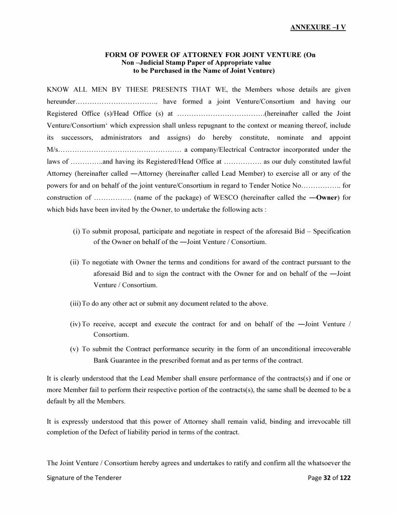
ANNEXURE –I V
FORM OF POWER OF ATTORNEY FOR JOINT VENTURE (On Non –Judicial Stamp Paper of Appropriate value
to be Purchased in the Name of Joint Venture)
KNOW ALL MEN BY THESE PRESENTS THAT WE, the Members whose details are given
hereunder…………………………….. have formed a joint Venture/Consortium and having our
Registered Office (s)/Head Office (s) at ……………………………….(hereinafter called the Joint
Venture/Consortium‘ which expression shall unless repugnant to the context or meaning thereof, include
its successors, administrators and assigns) do hereby constitute, nominate and appoint
M/s……………………………………………. a company/Electrical Contractor incorporated under the
laws of …………..and having its Registered/Head Office at ……………. as our duly constituted lawful
Attorney (hereinafter called ―Attorney (hereinafter called Lead Member) to exercise all or any of the
powers for and on behalf of the joint venture/Consortium in regard to Tender Notice No…………….. for
construction of ……………. (name of the package) of WESCO (hereinafter called the ―Owner) for
which bids have been invited by the Owner, to undertake the following acts :
(i) To submit proposal, participate and negotiate in respect of the aforesaid Bid – Specification
of the Owner on behalf of the ―Joint Venture / Consortium.
(ii) To negotiate with Owner the terms and conditions for award of the contract pursuant to the
aforesaid Bid and to sign the contract with the Owner for and on behalf of the ―Joint
Venture / Consortium.
(iii) To do any other act or submit any document related to the above.
(iv) To receive, accept and execute the contract for and on behalf of the ―Joint Venture /
Consortium.
(v) To submit the Contract performance security in the form of an unconditional irrecoverable
Bank Guarantee in the prescribed format and as per terms of the contract.
It is clearly understood that the Lead Member shall ensure performance of the contracts(s) and if one or
more Member fail to perform their respective portion of the contracts(s), the same shall be deemed to be a
default by all the Members.
It is expressly understood that this power of Attorney shall remain valid, binding and irrevocable till
completion of the Defect of liability period in terms of the contract.
The Joint Venture / Consortium hereby agrees and undertakes to ratify and confirm all the whatsoever the
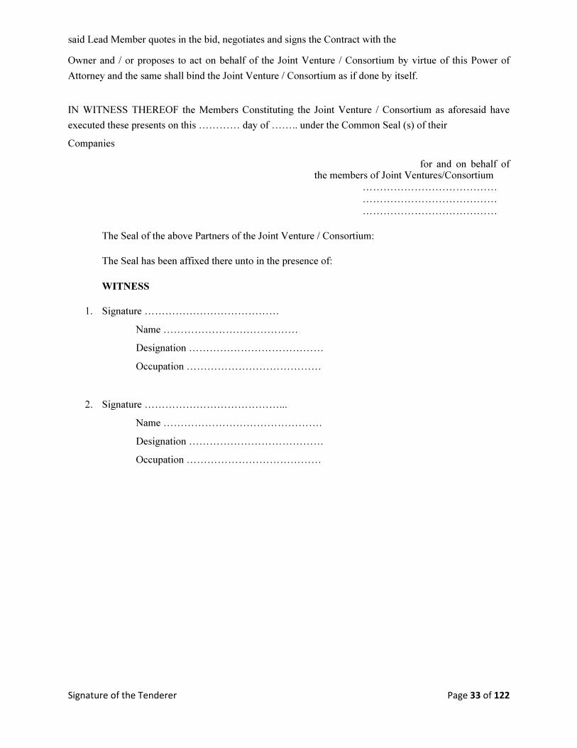
Signature of the Tenderer Page 33 of 122
said Lead Member quotes in the bid, negotiates and signs the Contract with the Owner and / or proposes to act on behalf of the Joint Venture / Consortium by virtue of this Power of
Attorney and the same shall bind the Joint Venture / Consortium as if done by itself.
IN WITNESS THEREOF the Members Constituting the Joint Venture / Consortium as aforesaid have
executed these presents on this ………… day of …….. under the Common Seal (s) of their Companies
for and on behalf of the members of Joint Ventures/Consortium
…………………………………
…………………………………
…………………………………
The Seal of the above Partners of the Joint Venture / Consortium:
The Seal has been affixed there unto in the presence of:
WITNESS
1. Signature …………………………………
Name …………………………………
Designation …………………………………
Occupation …………………………………
2. Signature …………………………………...
Name ……………………………………….
Designation …………………………………
Occupation …………………………………
Signature of the Tenderer Page 34 of 122
ANNEXURE – V
FORM OF JOINT VENTURE/ CONSORTIUM AGREEMENT
(To be executed on non-judicial stamp paper of appropriate value to be purchased in the name of executants or as required by the Jurisdiction in which executed)
THIS Joint Venture/Consortium Agreement executed on this ……….. day of …………… Two thousand
…………………… by:
M/s. …………….…………….a company/Partnership Firm/Sole Proprietorship Organization
incorporated under the …………….……………. Act/Laws and having its Registered Office/Head Office
at ……………. …………….……………. ……………. (hereinafter called the "Lead Member/First
Member" which expression shall include its successors),and
M/s. …………….…………….a company/Partnership Firm/Sole Proprietorship Organization
incorporated under the …………….……………. Act/Laws and having its Registered Office/Head Office
at ……………. …………….……………. ……………. (hereinafter called the " Second Member" which
expression shall include its successors),and
M/s. …………….…………….a company/Partnership Firm/Sole Proprietorship Organization
incorporated under the …………….……………. Act/Laws and having its Registered Office/Head Office
at ……………. …………….……………. ……………. (hereinafter called the "Third Member" which
expression shall include its successors),and
M/s. …………….…………….a company/Partnership Firm/Sole Proprietorship Organization
incorporated under the …………….……………. Act/Laws and having its Registered Office/Head Office
at ……………. …………….……………. ……………. (hereinafter called the "Fourth Member" which
expression shall include its successors).
The Lead Member/First Member, Second Member, the Third Member and the Fourth Member shall
collectively hereinafter be called as the ―Joint venture/Consortium Members for the purpose of
submitting a bid proposal to Western Electricity Supply Company of Odisha Ltd. (hereinafter referred to
as WESCO) being a company incorporated under the Companies Act. 1956 having its Corporate Office at
Burla (hereinafter called the ―Owner) in response to the invitation of bids (hereinafter called as
―Tender Notice No……………. Document) dated…………….. for supply, erection, Testing &
Commissioning as per the scope of work ……………….(hereinafter called as ―the Transaction)
WHEREAS Clause-2 of the Invitation for Bids (IFB), stipulates that two or more bidder(s) may
form a joint venture/Consortium among them and apply against this tender specification, provided they
fulfill the following eligible criteria; 1.0 They should have legally valid Consortium agreement as per the prescribed format for the purpose of
participation in the bidding process. The total no of a Consortium shall be limited to four members. 2.0 One of the Joint Venture/Consortium members should be a Electrical Contractor having valid HT
License.
Signature of the Tenderer Page 35 of 122
3.0 Consortium as a whole shall meet the qualifying norms specified in the tender, they participate.
4.0 The lead member of the Consortium should meet at least 50% of the qualifying norms in respect to
the work experience & Turn Over requirement. 5.0 Besides the lead member, other member(s) of the Consortium together shall meet the balance 50% of
the qualifying norms in respect to the work experience & Turn Over requirement. 6.0 All the Consortium member(s) shall authorize the lead partner by submitting a power of Attorney as
per the prescribed format duly signed by the authorized signatories. The lead partner shall be authorized
to receive instructions for and on behalf of all partners of the Consortium and entire execution of the
contract. 7.0 The Consortium and its members shall be jointly and severally responsible and be held liable for the
purpose of guaranteed obligation and any other matter as required under the contract. 8.0 Any member of the Consortium member(s) shall not be eligible either in an individual capacity or
part of any other Consortium to participate in the tender, where the said Consortium participates. 9.0 Work Order(s) will be placed to lead members of the Consortium. 10.0 In addition to the above the Lead Member of the bidder(s) should submit the following documents in
part-I bid as qualifying terms. Valid electrical (HT) license for Electrical Works. PAN & TIN No. EPF registration. 11. The Lead Member of the Bidder(s) shall have to furnish service tax registration, ESI and Labour
license within 45 days of receipt of the order. 12. The prescribed format for Power of Attorney (Annexure-IV) is provided in the tender specification as
enclosures.
AND WHEREAS the members of the Joint Venture/Consortium together shall strictly comply the eligible
criteria of the Clause-2 of the Invitation for Bids (IFB).
AND WHEREAS bid has been proposed to be submitted to the Owner by Lead Member based on this
Joint Venture/Consortium agreement all the members, signed by all the members.
NOW THIS INDENTURE WITNESSETH AS UNDER:
In consideration of the above premises, in the event of the selection of Joint Venture/Consortium as
successful bidder, all the parties to this Joint Venture/Consortium Agreement do hereby agree abide
themselves as follows:
Signature of the Tenderer Page 36 of 122
1. M/s ……………………………. Shall act as Lead Member for and on behalf of Joint
Venture/ Consortium Members. The said Joint Venture/Consortium members further declare and
confirm that they shall jointly and severally be bound and shall be fully responsible to the Owner for
supply, erection, Testing & commissioning as per the scope of work and successful performance of
the works, obligations under the same by the Lead Member are as follows:
i) Despite any breach by the Lead Member or other Member(s) of the Joint Venture/Consortium
agreement, the Member(s) do hereby agree and undertake to ensure full and effectual and
successful performance of the contract with the Owner and to carry out all the obligations and
responsibilities under the said Contract in accordance with the requirements of the Contract.
ii) If the Owner suffers any loss or damage on account of any breach in the Contract or any shortfall in
the performance of the equipment in meeting the performance guaranteed as per the specification in
terms of the Contract, the Members (s) of these presents undertake to promptly make good such loss
or damages caused to the Owner, on its demand without any demur. It. shall not be necessary or
obligatory for the Owner to proceed against Lead Member to these presents before proceeding against
or dealing with the other Members(s). The obligation of each of the member is absolute and not
independent of the Joint Venture/Consortium or any member. iii) The financial liability of the Members of this Joint Venture/Consortium agreement to the Owner, with
respect to any of the claims arising out of the performance of non-performance of the obligations set
forth in the said Joint Venture/Consortium agreement, read in conjunction with the relevant
conditions of the Contract shall, however, not be limited in any way so as to restrict or limit the
liabilities of any of the Partners of the Joint Venture/Consortium agreement. The liability of each
Member is absolute and not severable. iv) It is expressly understood and agreed between the Members to this Joint Venture/Consortium
agreement that the responsibilities inter se amongst the Members shall not in any way be a limitation
of joint and several responsibilities and liabilities of the Members to the Owner. It is clearly
understood that the Lead member shall ensure performance under the agreements and if one or more
Joint venture/Consortium Member(s) fail to perform its/their respective obligations under the
agreement(s), the same shall be deemed to be a default by all the Joint venture/Consortium Members.
It will be open for the Owner to take any steps, punitive and corrective action including the
termination of contract in case of such default also. v) This Joint Venture agreement shall be construed and interpreted in accordance with the laws of India
and the courts of Odisha shall have the exclusive jurisdiction within Balangir in all matters arising
there under.
vi) In case of an award of a Contract, all the Members to the Joint Venture/Consortium agreement do
hereby agree that Lead Partner shall furnish Performance Bank Guarantee for value of 10% of the
Contract Price and additional 1% by the other Joint Venture/ Consortium Member in the form of
an unconditional irrecoverable Bank Guarantee in the prescribed format and as per terms of the
contract.
Signature of the Tenderer Page 37 of 122
vii) It is further agreed that the Joint Venture/Consortium agreement shall be irrevocable and shall form
an integral part of the Contract, and shall continue to be enforceable till the Owner discharges the
same. It shall be effective from the date first mentioned above for all purposes and intents.
viii) Capitalized terms used but not defined herein shall have same meaning as assigned to them in the
Tender Documents and/or the agreements.
ix) In case of any dispute amongst the members of the Joint Venture/Consortium, Owner shall not be in
any way liable and also the Consortium members shall not be absolved from the contractual
obligation in any manner.
IN WITNESS WHEREOF the Members to the Joint Venture/Consortium agreement have through their
authorized representatives executed these presents and affixed Seals of their companies, on the day,
month and year first mentioned above.
1. For Lead Member/First Member (Signature
of authorized representative)
Name... …………….…………….
Signature.. ………….…………….
Designation …….…………….
2. For Second Member
(Signature of authorized representative)
Name... …………….…………….
Signature.. ………….…………….
Designation ……….…………….
3. For Third Member
Signature of authorized representative)
Name... …………….…………….
Signature.. ………….…………….
Designation ……….…………….
4. For Fourth Member
Signature of authorized representative)
Name... …………….…………….
Signature.. ………….…………….
Designation ……….…………….
WITNESSES:
1.…………….…………….…………. 2…………….…………….………….
(Signature) (Signature)
Name …………..…………….…… Name …………….…………….…
(Detail address) (Detail address)

Signature of the Tenderer Page 38 of 122
ANNEXURE – VI (A)
LETTER OF COMPLIANCE OF QUALIFYING REQUIREMENT (In case of Bidder being a Single Firm)
To The Collector &District Magistrate Balangir, Odisha Dear Sir, I/We ……………. (Name of Bidder) are submitting the bid as a single firm. In support of our
meeting the Qualifying requirements (QR) for bidders, stipulated in this tender specification, we
furnish herewith the details/documents etc. as follows.
Table – A: Previous Works Experience:
Qty Installed &
Commissioned
Documents
provided in
Description
proof of having
executed the
Package of
Name
works during
Quoted Proposed
Tender Sl.
of
Qty
the relevant
for Works Qty No. FY Client WO Ref Installed FY.
Table – B: Average Annual Turnover:
Estimated Annual Turnover Data
Cost of the (Rs. in Lakh)
Package Turnover
Package Quoted for (Rs. in Lakh) Financial Year (Rs. in Lakh)
Last Three Year preceding to
the year of tender
Total Estimated Cost of
Average Turnover
the packages quoted for
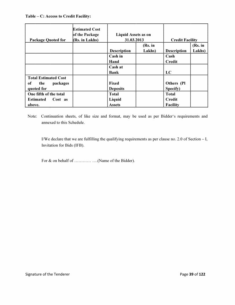
Signature of the Tenderer Page 39 of 122
Table – C: Access to Credit Facility:
Estimated Cost
of the Package Liquid Assets as on
Package Quoted for (Rs. in Lakhs) 31.03.2013 Credit Facility
(Rs. in (Rs. in
Description Lakhs) Description Lakhs)
Cash in Cash
Hand Credit
Cash at
Bank LC
Total Estimated Cost
of the packages Fixed Others (Pl
quoted for Deposits Specify)
One fifth of the total Total Total
Estimated Cost as Liquid Credit
above. Assets Facility
Note: Continuation sheets, of like size and format, may be used as per Bidder‘s requirements and
annexed to this Schedule.
I/We declare that we are fulfilling the qualifying requirements as per clause no. 2.0 of Section – I,
Invitation for Bids (IFB).
For & on behalf of ………… ….(Name of the Bidder).

Signature of the Tenderer Page 40 of 122
ANNEXURE – VI (B)
LETTER OF COMPLIANCE OF QUALIFYING REQUIREMENT (In case of Bidder being a Joint Venture / Consortium Firm)
To, The Collector &District Magistrate
Balangir, Odisha
Dear Sir,
I/We ……………. (Name of Bidder) are submitting the bid as a Consortium/Joint Venture. In support of
our meeting the Qualifying requirements (QR) for bidders, stipulated in this tender specification, we
furnish herewith the details/documents etc. as follows.
Name of the members of the JV / Consortium
1.
2.
3. Table – A: Previous Works Experience: Name of the Member (any one member only)
Qty Installed & Commissioned
Documents
provided in
proof of
having
Description executed the
Package of Name works during
Quoted Proposed Tender Sl. of Qty the relevant
for Works Qty No. FY Client WO Ref Installed FY.

Signature of the Tenderer Page 41 of 122
Table – B: Average Annual Turnover: (All the members of JV/Consortium taken together)
Total Annual
Annual Turnover Annual Turnover Turnover
(Rs. in Lakh) (Rs. in Lakh) (Rs. in Lakh)
Estima Name of Name of Name of
ted Member 1 Member 2 Member 2
Cost of Turn
the over
Packag Turnov Turno (Rs.
e er ver in
Package Quoted (Rs. in Financial (Rs. in Financial (Rs. in Financial Lakh for Lakh) Year Lakh) Year Lakh) Year )
Total Total Total
Total Estimated Average
Cost of the Turnover
packages quoted
for

Signature of the Tenderer Page 42 of 122
Table – C: Access to Credit Facility: (All the members of JV/Consortium taken together)
Estimated Cost
Package Quoted for of the Package Liquid Assets as on Credit Facility (Rs. in Lakh) 31.03.2013
Member 1 Member 1
(Rs. in (Rs. in
Description Lakh) Description Lakh)
Cash in Cash
Hand Credit
Cash at
Bank LC
Fixed Others (Pl
Deposits Specify)
Total Liquid Total Credit
Assets Facility
Liquid Assets as on Credit Facility 31.03.2013
Member 2 Member 2
Description (Rs. in Description (Rs. in
Lakh) Lakh)
Cash in Cash
Hand Credit
Cash at
Bank LC
Fixed Others (Pl
Deposits Specify)
Total Total
Liquid Credit
Assets Facility
Liquid Assets as on
31.03.2013 Credit Facility
Total for Total for
JV 2 JV 2
(Rs. in (Rs. in
Description Lakh) Description Lakh)
Cash in Cash
Hand Credit
Cash at
Bank LC
Total Estimated Cost of Fixed Others (Pl
the packages quoted for Deposits Specify)
Total Total
One fifth of the total Liquid Credit
Estimated Cost as above. Assets Facility
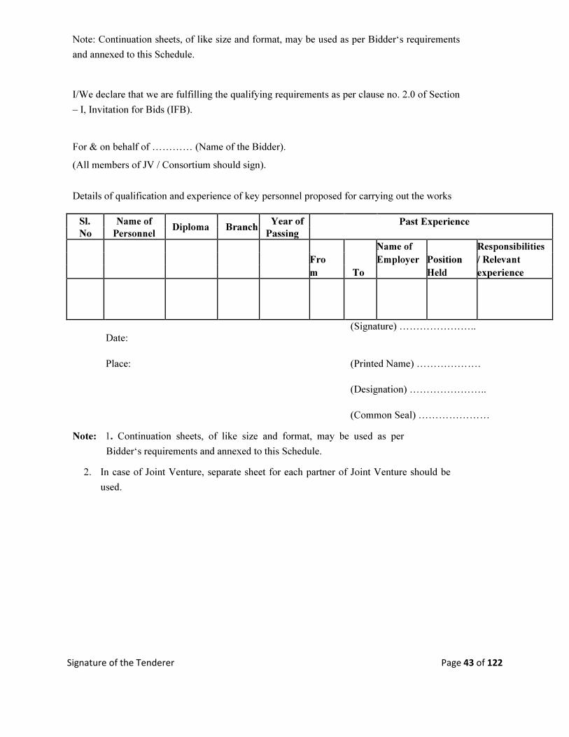
Signature of the Tenderer Page 43 of 122
Note: Continuation sheets, of like size and format, may be used as per Bidder‘s requirements
and annexed to this Schedule.
I/We declare that we are fulfilling the qualifying requirements as per clause no. 2.0 of Section
– I, Invitation for Bids (IFB).
For & on behalf of ………… (Name of the Bidder).
(All members of JV / Consortium should sign).
Details of qualification and experience of key personnel proposed for carrying out the works
Sl. Name of Diploma Branch
Year of Past Experience
No Personnel Passing
Name of Responsibilities
Fro Employer Position / Relevant
m To Held experience
Date:
(Signature) …………………..
Place: (Printed Name) ……………….
(Designation) …………………..
(Common Seal) ………………… Note: 1. Continuation sheets, of like size and format, may be used as per
Bidder‘s requirements and annexed to this Schedule.
2. In case of Joint Venture, separate sheet for each partner of Joint Venture should be
used.
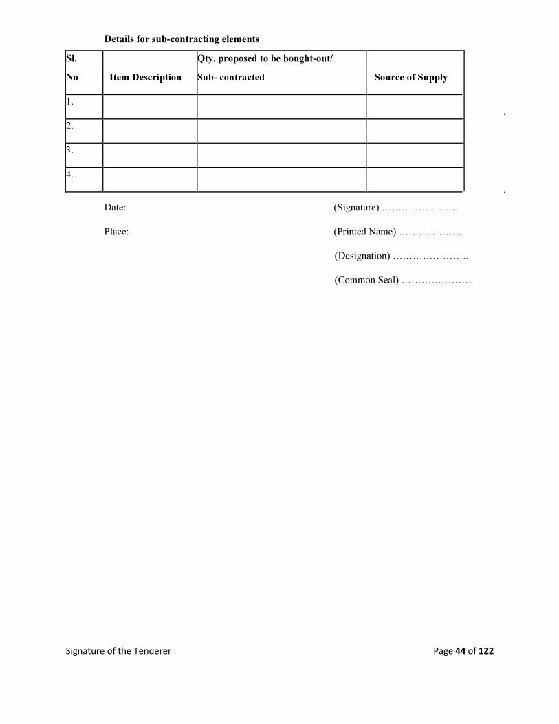
Signature of the Tenderer Page 44 of 122
Details for sub-contracting elements
Sl. Qty. proposed to be bought-out/
No Item Description Sub- contracted Source of Supply
1.
2.
3.
4.
Date: (Signature) …………………..
Place: (Printed Name) ……………….
(Designation) …………………..
(Common Seal) …………………
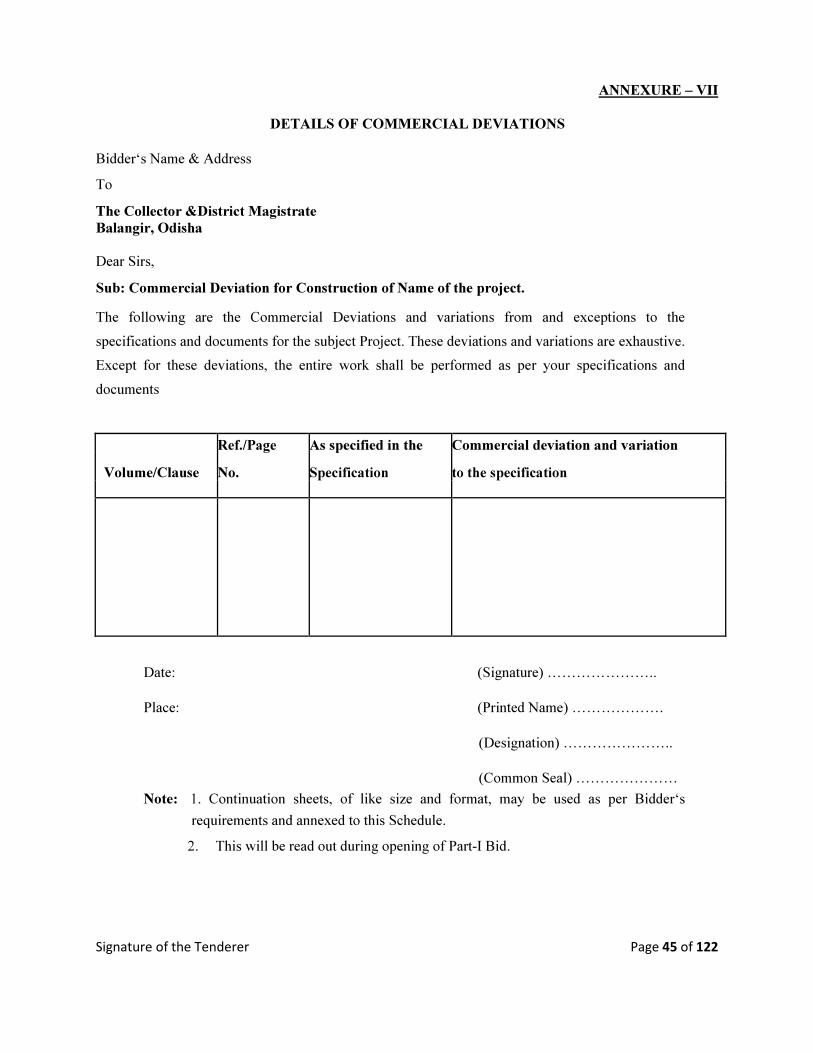
Signature of the Tenderer Page 45 of 122
ANNEXURE – VII
DETAILS OF COMMERCIAL DEVIATIONS
Bidder‘s Name & Address To The Collector &District Magistrate
Balangir, Odisha
Dear Sirs, Sub: Commercial Deviation for Construction of Name of the project. The following are the Commercial Deviations and variations from and exceptions to the
specifications and documents for the subject Project. These deviations and variations are exhaustive.
Except for these deviations, the entire work shall be performed as per your specifications and
documents
Ref./Page As specified in the Commercial deviation and variation
Volume/Clause No. Specification to the specification
Date: (Signature) …………………..
Place: (Printed Name) ……………….
(Designation) …………………..
(Common Seal) …………………
Note: 1. Continuation sheets, of like size and format, may be used as per Bidder‘s
requirements and annexed to this Schedule.
2. This will be read out during opening of Part-I Bid.

Signature of the Tenderer Page 46 of 122
ANNEXURE – VIII
DETAILS TECHNICAL DEVIATIONS
Bidder‘s Name & Address
To, The Collector &District Magistrate
Balangir, Odisha
Dear Sirs, Sub: Technical Deviation for Construction of ………………. (Name of the Project)
The following are the Technical Deviations and variations from and exceptions to the specifications and
documents for the subject package. These deviations and variations are exhaustive. Except for these
deviations, the entire work shall be performed as per your specifications and documents As specified in the Technical deviation and
Volume/Clause Ref./Page No.
Specification / Relevant variation to the
ISS specification
Date: (Signature) …………………..
Place: (Printed Name) ……………….
(Designation) …………………..
(Common Seal) …………………
Note: 1. Continuation sheets, of like size and format, may be used as per Bidder‘s
requirements and annexed to this Schedule.
2. The deviations and variations, if any, shall be brought out separately for each of the
equipment.
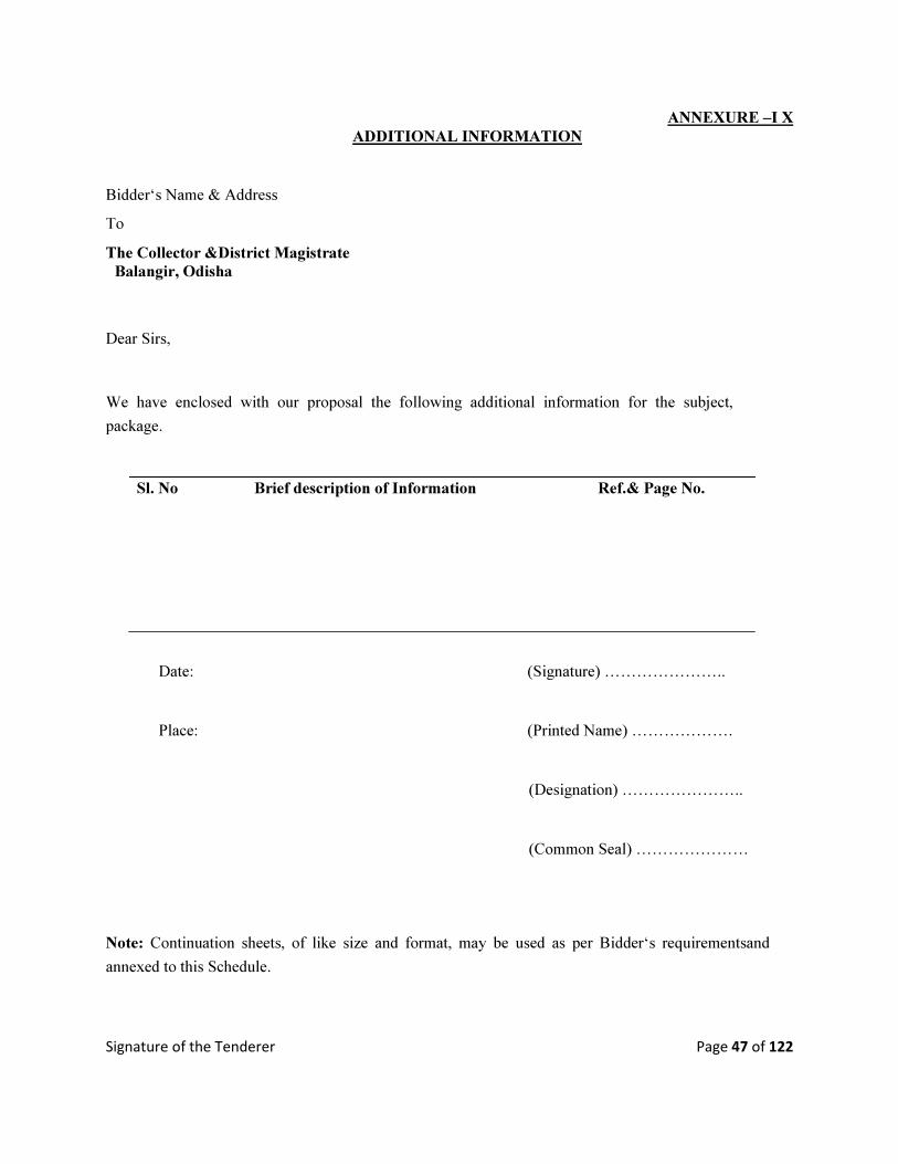
Signature of the Tenderer Page 47 of 122
ANNEXURE –I X ADDITIONAL INFORMATION
Bidder‘s Name & Address To The Collector &District Magistrate
Balangir, Odisha Dear Sirs, We have enclosed with our proposal the following additional information for the subject,
package.
Sl. No Brief description of Information Ref.& Page No.
Date: (Signature) …………………..
Place: (Printed Name) ……………….
(Designation) …………………..
(Common Seal) ………………… Note: Continuation sheets, of like size and format, may be used as per Bidder‘s requirementsand
annexed to this Schedule.
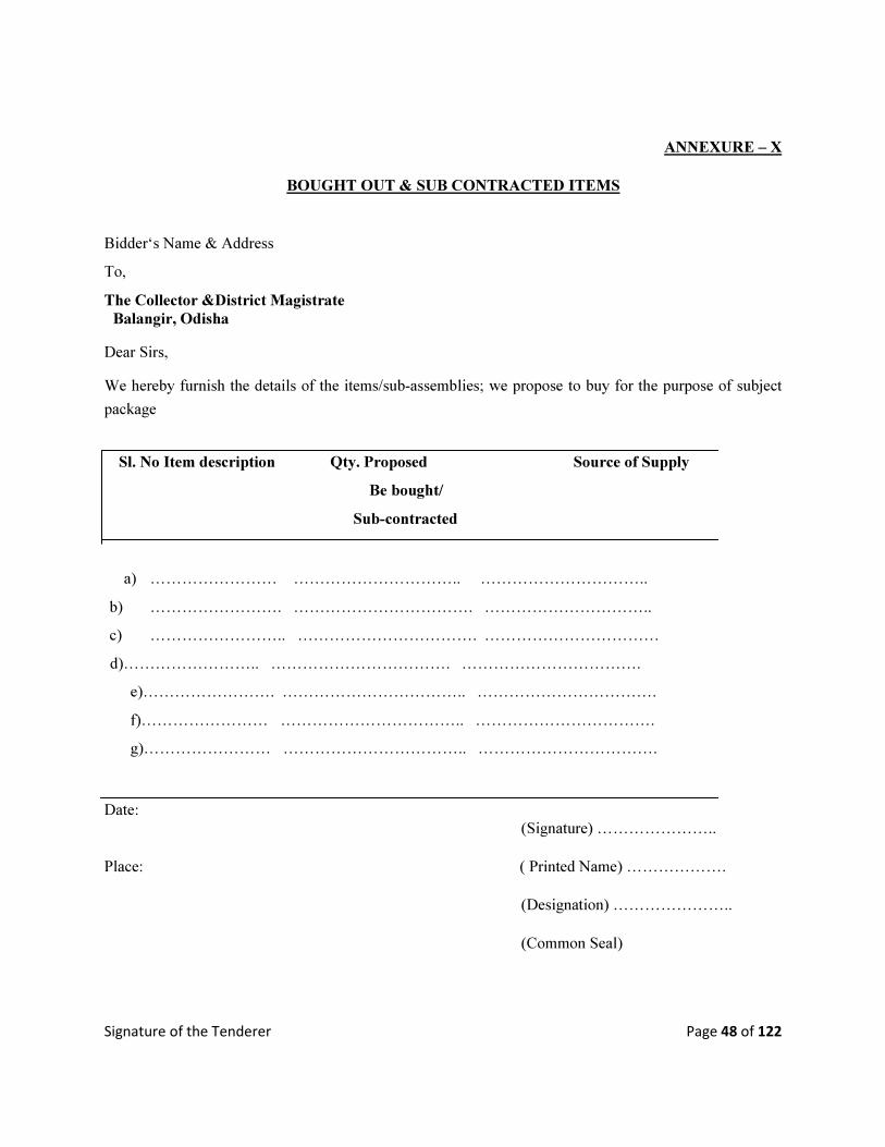
Signature of the Tenderer Page 48 of 122
ANNEXURE – X
BOUGHT OUT & SUB CONTRACTED ITEMS
Bidder‘s Name & Address To, The Collector &District Magistrate
Balangir, Odisha Dear Sirs, We hereby furnish the details of the items/sub-assemblies; we propose to buy for the purpose of subject
package
Sl. No Item description Qty. Proposed Source of Supply
Be bought/
Sub-contracted
a) …………………… ………………………….. ………………………….. b) ……………………. ……………………………. …………………………..
c) …………………….. ……………………………. ……………………………
d)…………………….. ……………………………. …………………………….
e)……………………. …………………………….. …………………………….
f)…………………… …………………………….. …………………………….
g)…………………… …………………………….. …………………………….
Date:
(Signature) …………………..
Place: ( Printed Name) ……………….
(Designation) …………………..
(Common Seal)
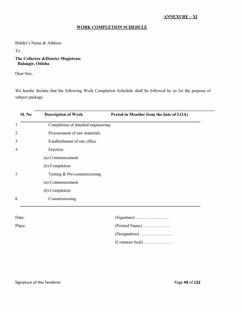
Signature of the Tenderer Page 49 of 122
ANNEXURE – XI
WORK COMPLETION SCHEDULE
Bidder‘s Name & Address To The Collector &District Magistrate
Balangir, Odisha
Dear Sirs, We hereby declare that the following Work Completion Schedule shall be followed by us for the purpose of
subject package
Sl. No Description of Work Period in Months( from the date of LOA)
1 Completion of detailed engineering
2 Procurement of raw materials
3 Establishment of site office
4 Erection
(a) Commencement
(b) Completion
5 Testing & Pre-commissioning
(a) Commencement
(b) Completion
6 Commissioning
Date: (Signature) …………………..
Place: (Printed Name) ……………….
(Designation) …………………..
(Common Seal) ………………..
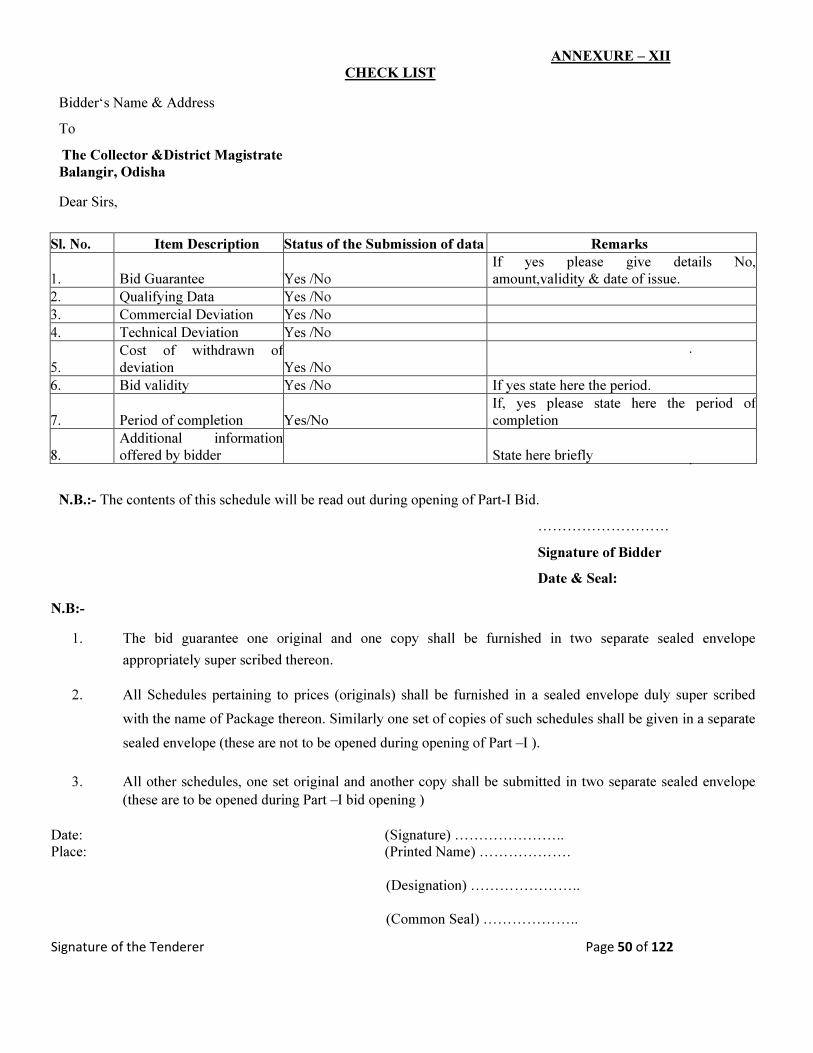
Signature of the Tenderer Page 50 of 122
ANNEXURE – XII CHECK LIST
Bidder‘s Name & Address
To
The Collector &District Magistrate
Balangir, Odisha
Dear Sirs,
Sl. No. Item Description Status of the Submission of data Remarks
1. Bid Guarantee Yes /No
If yes please give details No,
amount,validity & date of issue.
2. Qualifying Data Yes /No
3. Commercial Deviation Yes /No
4. Technical Deviation Yes /No
5.
Cost of withdrawn of
deviation Yes /No
6. Bid validity Yes /No If yes state here the period.
7. Period of completion Yes/No
If, yes please state here the period of
completion
8.
Additional information
offered by bidder State here briefly N.B.:- The contents of this schedule will be read out during opening of Part-I Bid.
………………………
Signature of Bidder
Date & Seal:
N.B:-
1. The bid guarantee one original and one copy shall be furnished in two separate sealed envelope
appropriately super scribed thereon.
2. All Schedules pertaining to prices (originals) shall be furnished in a sealed envelope duly super scribed
with the name of Package thereon. Similarly one set of copies of such schedules shall be given in a separate
sealed envelope (these are not to be opened during opening of Part –I ).
3. All other schedules, one set original and another copy shall be submitted in two separate sealed envelope
(these are to be opened during Part –I bid opening )
Date: (Signature) …………………..
Place: (Printed Name) ……………….
(Designation) …………………..
(Common Seal) ………………..
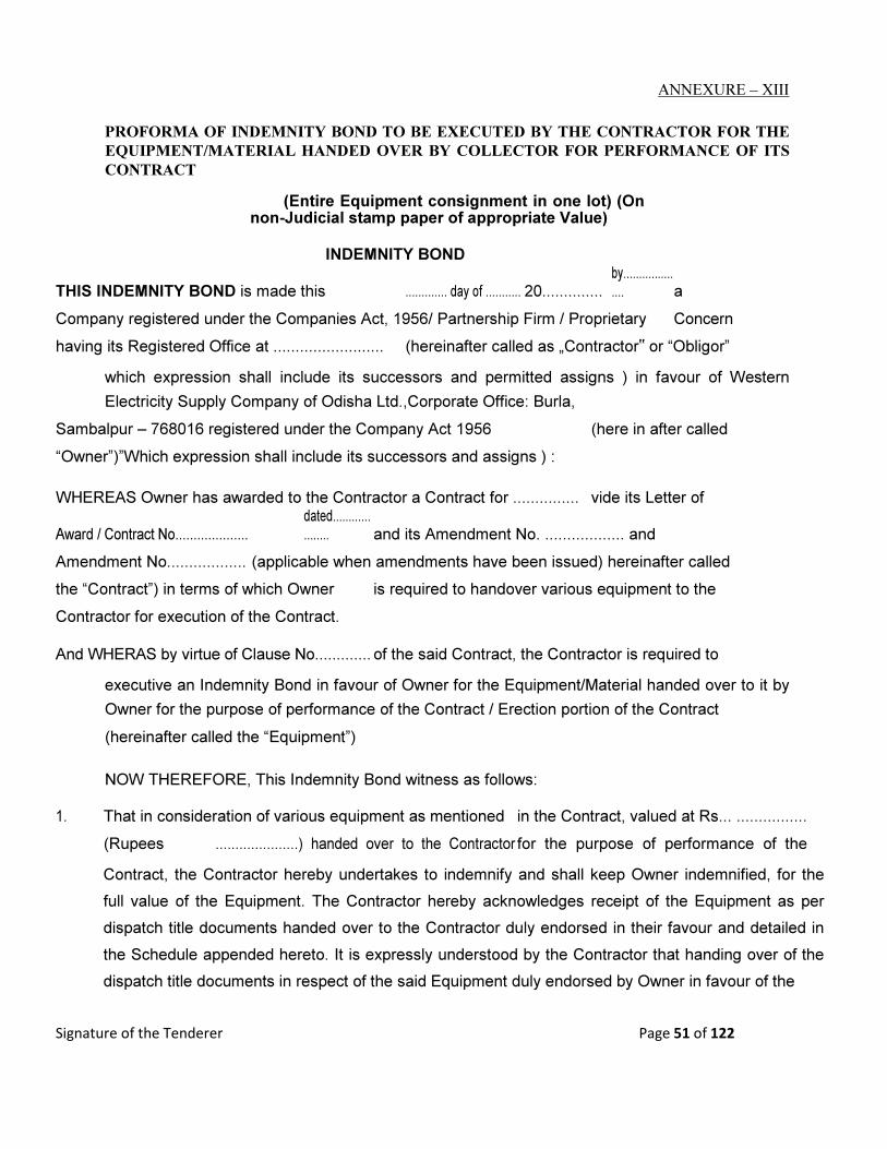
Signature of the Tenderer Page 51 of 122
ANNEXURE – XIII
PROFORMA OF INDEMNITY BOND TO BE EXECUTED BY THE CONTRACTOR FOR THE
EQUIPMENT/MATERIAL HANDED OVER BY COLLECTOR FOR PERFORMANCE OF ITS
CONTRACT
(Entire Equipment consignment in one lot) (On non-Judicial stamp paper of appropriate Value)
INDEMNITY BOND
THIS INDEMNITY BOND is made this ............. day of ........... 20.............. by.................... a
Company registered under the Companies Act, 1956/ Partnership Firm / Proprietary Concern
having its Registered Office at ......................... (hereinafter called as „Contractor‟ or “Obligor”
which expression shall include its successors and permitted assigns ) in favour of Western
Electricity Supply Company of Odisha Ltd.,Corporate Office: Burla, Sambalpur – 768016 registered under the Company Act 1956 (here in after called
“Owner”)”Which expression shall include its successors and assigns ) :
WHEREAS Owner has awarded to the Contractor a Contract for ............... vide its Letter of
Award / Contract No....................
dated.................... and its Amendment No. .................. and
Amendment No.................. (applicable when amendments have been issued) hereinafter called
the “Contract”) in terms of which Owner is required to handover various equipment to the
Contractor for execution of the Contract.
And WHERAS by virtue of Clause No............. of the said Contract, the Contractor is required to
executive an Indemnity Bond in favour of Owner for the Equipment/Material handed over to it by
Owner for the purpose of performance of the Contract / Erection portion of the Contract
(hereinafter called the “Equipment”)
NOW THEREFORE, This Indemnity Bond witness as follows:
1. That in consideration of various equipment as mentioned in the Contract, valued at Rs... ................
(Rupees .....................) handed over to the Contractor for the purpose of performance of the
Contract, the Contractor hereby undertakes to indemnify and shall keep Owner indemnified, for the
full value of the Equipment. The Contractor hereby acknowledges receipt of the Equipment as per
dispatch title documents handed over to the Contractor duly endorsed in their favour and detailed in
the Schedule appended hereto. It is expressly understood by the Contractor that handing over of the
dispatch title documents in respect of the said Equipment duly endorsed by Owner in favour of the

Signature of the Tenderer Page 52 of 122
Contractor shall be construed as handing over of the Equipment purported to be covered by such title
documents and the Contractor shall hold such Equipment is trust as a Trustee for and on behalf of
Owner. 2. That the Contractor is obliged and shall remain absolutely responsible for the safe transit / protection
and custody of the Equipment at Owner project Site against all risks, whatsoever, till the Equipment
are duly used / erected in accordance with the terms of the Contract and the Plant / Package duly
erected and commissioned in accordance with the terms of the Contract, is taken over by Owner. The
Contractor undertakes to keep Owner harmless against any loss or damage that may be caused to
the Equipment.
3. The Contractor undertakes that the Equipment shall be used exclusively for the performance /
execution of the Contract strictly in accordance with its terms and conditions and no part of the
equipment shall be utilized for any other work or purpose whatsoever. It is clearly understood by the
Contractor that non-observance of the obligations under this Indemnity Bond by the Contractor shall
inter-alia constitute a criminal breach of trust on the part of the Contractor for all intents and purpose
including legal / penal consequences .
.
4. That COLLECTOR (as the case may be) is and shall remain the exclusive Owner of the
Equipment free from all encumbrances, charges or liens of any kind, whatsoever. The
Equipment shall at all times be open to inspection and checking by Engineer in Charge /
Engineer or other employees/agents authorized by him in this regard. Further, Owner shall
always be free at all times to take possession of the Equipment in whatever form the Equipment
may be, if in its opinion the Equipment are likely to be endangered, misutilised or converted to
uses other than those specified in the Contract, by any acts of omission or commission on the
part of the Contractor binds himself and undertakes to comply with the direction of demand of
Owner to return the Equipment without any demur or reservation.
5. That this indemnity Bond is irrevocable. If at any time any loss or damage occurs to the Equipment
or the same or any part thereof is misutilised in any manner whatsoever, then the Contractor hereby
agrees that the decision of the Engineer-in-Charge/Engineer of Owner as to assessment of loss or
damage to the Equipment shall be final and binding on the Contractor. The Contractor binds itself
and undertakes to replace the lost and/or damaged Equipment at its own cost and/or shall pay the
amount of loss of Owner without demur, reservation or protest. This is without prejudice to any other
right or remedy that may be available to Owner against the Contractor under the Contract and under
this Indemnity Bond

Signature of the Tenderer Page 53 of 122
6. NOW THE CONDITION of this Bond is that if the Contractor shall duly and punctually comply with
terms and conditions of this Bond to the satisfaction of Owner, THEN, the above Bond shall be void,
but otherwise, it shall remain in full force and virtue.
IN WITNESS WHEREOF, the Contractor has hereunto set its hand through its authorized representative
under the common seal of the Company, the day, month and year first above mentioned.
SCHEDULE
Particulars of Quantity Particulars of Dispatch Title Value of the Signature of the Documents Equipment Attorney (authorised
Equipment RR / GR / No. / Carrier representative as a handed over Date of Bill of token of receipt Lading
For an on behalf of M/s..............................................
WITNESS 1. 1. Signature ...................................... Signature .....................................
2. Name ........................................... Name ..........................................
3. Address........................................ Designation ................................
Authorised representative *
2. 1. Signature .....................................
2. Name .......................................... (Common Seal in case of Company)
3. Address .......................................
Indemnity Bonds are to be executed by the authorised person and (i) in case of Contracting
Company under common seal of the Company or (ii) having the Power of Attorney issued under
common seal of the company with authority to execute Indemnity Bonds, (iii) In case of (ii), the
original Power of Attorney if it is specifically for this Contract or a Photostat copy of the Power
of Attorney if it is General Power of Attorney and such documents should be attached to
Indemnity Bond.
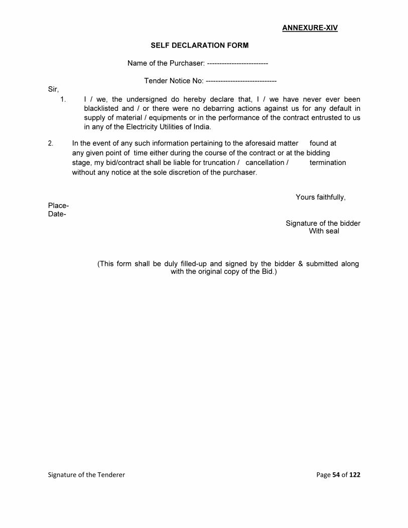
Signature of the Tenderer Page 54 of 122
ANNEXURE-XIV
SELF DECLARATION FORM
Name of the Purchaser: -------------------------
Tender Notice No: ----------------------------- Sir,
1. I / we, the undersigned do hereby declare that, I / we have never ever been
blacklisted and / or there were no debarring actions against us for any default in
supply of material / equipments or in the performance of the contract entrusted to us
in any of the Electricity Utilities of India. 2. In the event of any such information pertaining to the aforesaid matter found at
any given point of time either during the course of the contract or at the bidding
stage, my bid/contract shall be liable for truncation / cancellation / termination
without any notice at the sole discretion of the purchaser.
Yours faithfully, Place- Date-
Signature of the bidder With seal
(This form shall be duly filled-up and signed by the bidder & submitted along with the original copy of the Bid.)

Signature of the Tenderer Page 55 of 122
ANNEXURE – XV (A) PROFORMA FOR BANK GUARANTEE FOR EARNEST MONEY DEPOSIT
(ON NON-JUDICIAL STAMP PAPER OF Rs.100/-)
Ref Date Bank Guarantee No:
In accordance with invitation to Tender Notice No.--------- Dated ------------- of Collector
Balangir. for the execution of
______________________________________________________________ (name of package)
M/s__________________________Address__________________________________________
_________________________________________________________wish/wished to participate in the
said tender and as the Bank Guarantee for the sum of Rs.______________
[Rupees________________________________________ Valid for a period of ………… days
(in words) is required to be submitted by the Bidder.
1.We the________________________________________________[Indicate the Name of the
Bank] [Hereinafter referred to as ‗the Bank‘] at the request of M/S
___________________________________________________________ [Herein after referred to as
supplier (s)] do hereby unequivocally and unconditionally guarantee and undertake to pay during the
above said period, on written request by Collector Balangir an amount not exceeding
Rs._________________to the Collector , without any reservation. The guarantee would remain valid up
to 4.00 PM of _________________ [date] and if any further extension to this is required, the same will be
extended on receiving instructions from M/s
_______________________________________ on whose behalf this guarantee has been issued.
2. We the _____________________________________ [Indicate the name of the bank] do hereby
further undertake to pay the amounts due and payable under this guarantee without any demur, merely on
a demand from the Collector stating that the amount claimed is due by way of loss or damage caused to or
would be caused to or suffered by the COLLECTOR by reason of any breach by the said supplier [s] of
any of the terms or conditions or failure to perform the said Bid. Any such demand made on the Bank
shall be conclusive as regards the amount due and payable by the Bank under this guarantee. However,
our liability under this guarantee shall be restricted to an amount not exceeding
Rs.______________________________ (in wards)
3. We, the _______________ Bank undertake to pay the COLLECTOR any money so demanded not
withstanding any dispute or disputes so raised by the supplier [s] in any suit or proceeding
instituted/pending before any Court or Tribunal relating thereto, our liability under this agreement being
absolute and unequivocal. The payment so made by us under this bond shall be a valid
discharge of our liability for payment there under and the supplier(s) shall have no claim against us for making such payment.
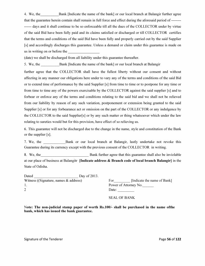
Signature of the Tenderer Page 56 of 122
4. We, the__________Bank [Indicate the name of the bank] or our local branch at Balangir further agree
that the guarantee herein contain shall remain in full force and effect during the aforesaid period of --------
------ days and it shall continue to be so enforceable till all the dues of the COLLECTOR under by virtue
of the said Bid have been fully paid and its claims satisfied or discharged or till COLLECTOR certifies
that the terms and conditions of the said Bid have been fully and properly carried out by the said Supplier
[s] and accordingly discharges this guarantee. Unless a demand or claim under this guarantee is made on
us in writing on or before the _________________ (date) we shall be discharged from all liability under this guarantee thereafter. 5. We, the __________Bank [Indicate the name of the bank] or our local branch at Balangir further agree that the COLLECTOR shall have the fullest liberty without our consent and without
affecting in any manner our obligations here under to vary any of the terms and conditions of the said Bid
or to extend time of performance by the said Supplier [s] from time to time or to postpone for any time or
from time to time any of the powers exercisable by the COLLECTOR against the said supplier [s] and to
forbear or enforce any of the terms and conditions relating to the said bid and we shall not be relieved
from our liability by reason of any such variation, postponement or extension being granted to the said
Supplier [s] or for any forbearance act or omission on the part of the COLLECTOR or any indulgence by
the COLLECTOR to the said Supplier[s] or by any such matter or thing whatsoever which under the law
relating to sureties would but for this provision, have effect of so relieving us. 6. This guarantee will not be discharged due to the change in the name, style and constitution of the Bank
or the supplier [s]. 7. We, the ____________Bank or our local branch at Balangir, lastly undertake not revoke this
Guarantee during its currency except with the previous consent of the COLLECTOR in writing. 8. We, the__________________________ Bank further agree that this guarantee shall also be inviolable
at our place of business at Balangitr [Indicate address & Branch code of local branch Balangir] in the
State of Odisha.
Dated ________________________ Day of 2013.
Witness ((Signature, names & address) For_________ [Indicate the name of Bank]
1. Power of Attorney No.______
2 Date: _________
SEAL OF BANK
Note: The non-judicial stamp paper of worth Rs.100/- shall be purchased in the name ofthe bank, which has issued the bank guarantee.
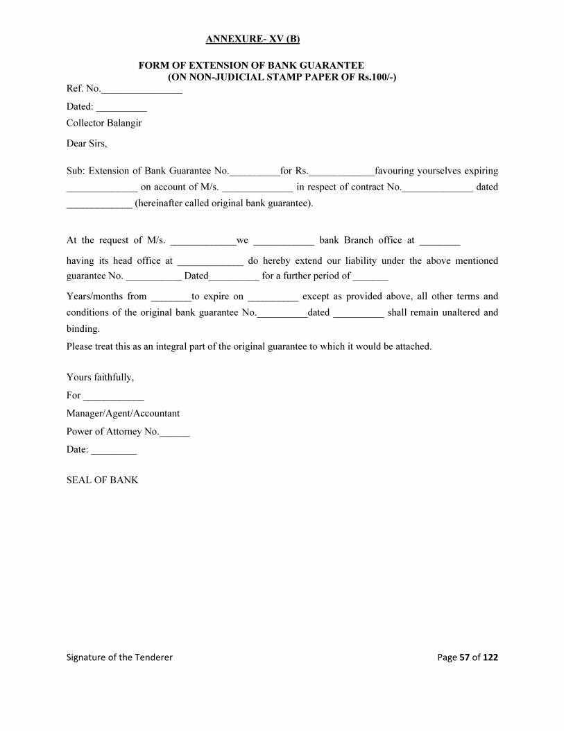
Signature of the Tenderer Page 57 of 122
ANNEXURE- XV (B)
FORM OF EXTENSION OF BANK GUARANTEE
(ON NON-JUDICIAL STAMP PAPER OF Rs.100/-) Ref. No.________________ Dated: __________ Collector Balangir Dear Sirs,
Sub: Extension of Bank Guarantee No.__________for Rs._____________favouring yourselves expiring
______________ on account of M/s. ______________ in respect of contract No.______________ dated
_____________ (hereinafter called original bank guarantee).
At the request of M/s. _____________we ____________ bank Branch office at ________ having its head office at _____________ do hereby extend our liability under the above mentioned
guarantee No. ___________ Dated__________ for a further period of _______ Years/months from ________to expire on __________ except as provided above, all other terms and
conditions of the original bank guarantee No.__________dated __________ shall remain unaltered and
binding. Please treat this as an integral part of the original guarantee to which it would be attached. Yours faithfully, For ____________ Manager/Agent/Accountant Power of Attorney No.______ Date: _________ SEAL OF BANK

Signature of the Tenderer Page 58 of 122
SECTION-IV
TECHNICAL BIDS
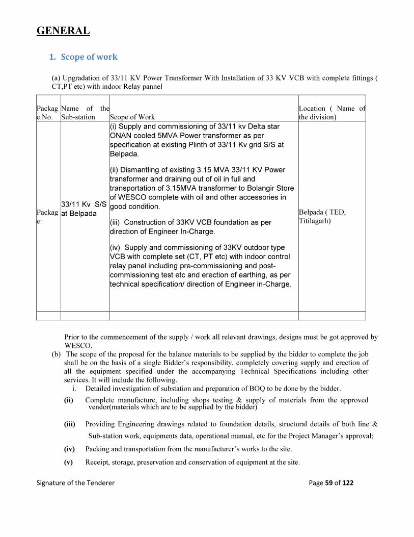
Signature of the Tenderer Page 59 of 122
GENERAL
1. Scope of work
(a) Upgradation of 33/11 KV Power Transformer With Installation of 33 KV VCB with complete fittings (
CT,PT etc) with indoor Relay pannel
Packag
e No.
Name of the
Sub-station Scope of Work
Location ( Name of
the division)
Packag
e:
33/11 Kv S/S
at Belpada
(i) Supply and commissioning of 33/11 kv Delta star
ONAN cooled 5MVA Power transformer as per
specification at existing Plinth of 33/11 Kv grid S/S at
Belpada.
(ii) Dismantling of existing 3.15 MVA 33/11 KV Power
transformer and draining out of oil in full and
transportation of 3.15MVA transformer to Bolangir Store
of WESCO complete with oil and other accessories in
good condition.
(iii) Construction of 33KV VCB foundation as per
direction of Engineer In-Charge.
(iv) Supply and commissioning of 33KV outdoor type
VCB with complete set (CT, PT etc) with indoor control
relay panel including pre-commissioning and post-
commissioning test etc and erection of earthing, as per
technical specification/ direction of Engineer in-Charge.
Belpada ( TED,
Titilagarh)
Prior to the commencement of the supply / work all relevant drawings, designs must be got approved by
WESCO.
(b) The scope of the proposal for the balance materials to be supplied by the bidder to complete the job
shall be on the basis of a single Bidder’s responsibility, completely covering supply and erection of
all the equipment specified under the accompanying Technical Specifications including other
services. It will include the following.
i. Detailed investigation of substation and preparation of BOQ to be done by the bidder.
(ii) Complete manufacture, including shops testing & supply of materials from the approved vendor(materials which are to be supplied by the bidder)
(iii) Providing Engineering drawings related to foundation details, structural details of both line &
Sub-station work, equipments data, operational manual, etc for the Project Manager’s approval;
(iv) Packing and transportation from the manufacturer’s works to the site.
(v) Receipt, storage, preservation and conservation of equipment at the site.
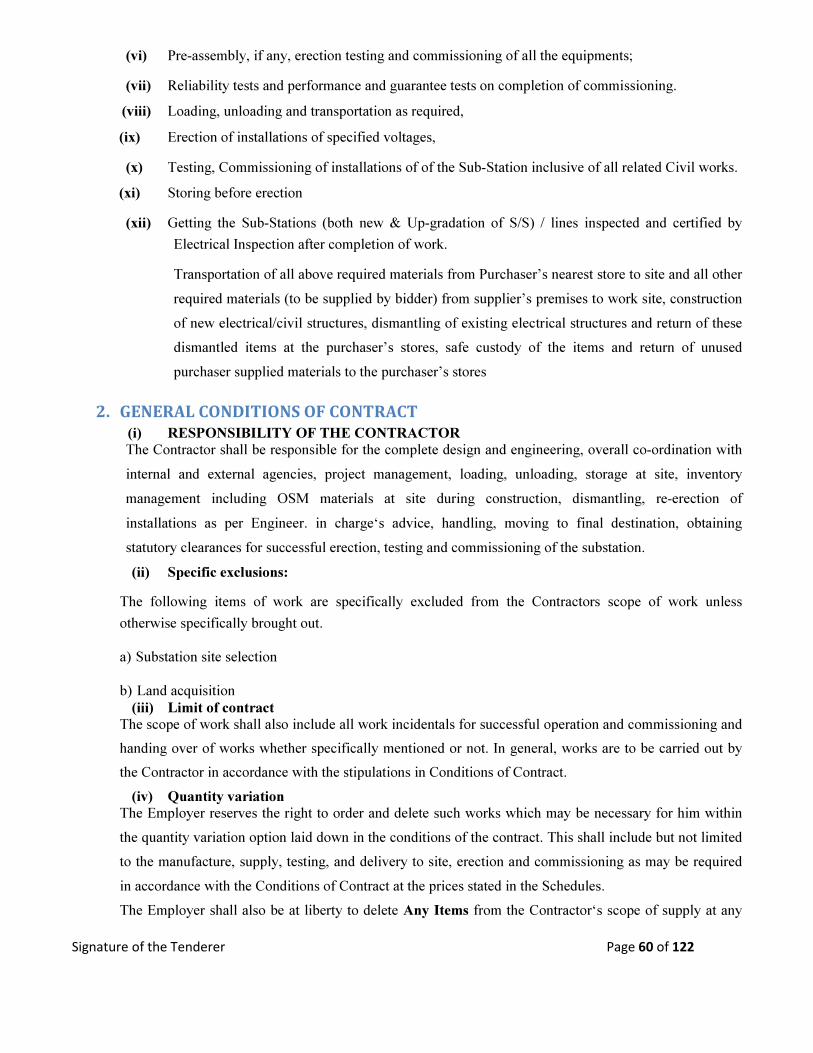
Signature of the Tenderer Page 60 of 122
(vi) Pre-assembly, if any, erection testing and commissioning of all the equipments;
(vii) Reliability tests and performance and guarantee tests on completion of commissioning.
(viii) Loading, unloading and transportation as required,
(ix) Erection of installations of specified voltages,
(x) Testing, Commissioning of installations of of the Sub-Station inclusive of all related Civil works.
(xi) Storing before erection
(xii) Getting the Sub-Stations (both new & Up-gradation of S/S) / lines inspected and certified by
Electrical Inspection after completion of work. Transportation of all above required materials from Purchaser’s nearest store to site and all other
required materials (to be supplied by bidder) from supplier’s premises to work site, construction
of new electrical/civil structures, dismantling of existing electrical structures and return of these
dismantled items at the purchaser’s stores, safe custody of the items and return of unused
purchaser supplied materials to the purchaser’s stores
2. GENERAL CONDITIONS OF CONTRACT
(i) RESPONSIBILITY OF THE CONTRACTOR The Contractor shall be responsible for the complete design and engineering, overall co-ordination with
internal and external agencies, project management, loading, unloading, storage at site, inventory
management including OSM materials at site during construction, dismantling, re-erection of
installations as per Engineer. in charge‘s advice, handling, moving to final destination, obtaining
statutory clearances for successful erection, testing and commissioning of the substation.
(ii) Specific exclusions:
The following items of work are specifically excluded from the Contractors scope of work unless
otherwise specifically brought out.
a) Substation site selection
b) Land acquisition
(iii) Limit of contract The scope of work shall also include all work incidentals for successful operation and commissioning and
handing over of works whether specifically mentioned or not. In general, works are to be carried out by
the Contractor in accordance with the stipulations in Conditions of Contract.
(iv) Quantity variation The Employer reserves the right to order and delete such works which may be necessary for him within
the quantity variation option laid down in the conditions of the contract. This shall include but not limited
to the manufacture, supply, testing, and delivery to site, erection and commissioning as may be required
in accordance with the Conditions of Contract at the prices stated in the Schedules.
The Employer shall also be at liberty to delete Any Items from the Contractor‘s scope of supply at any
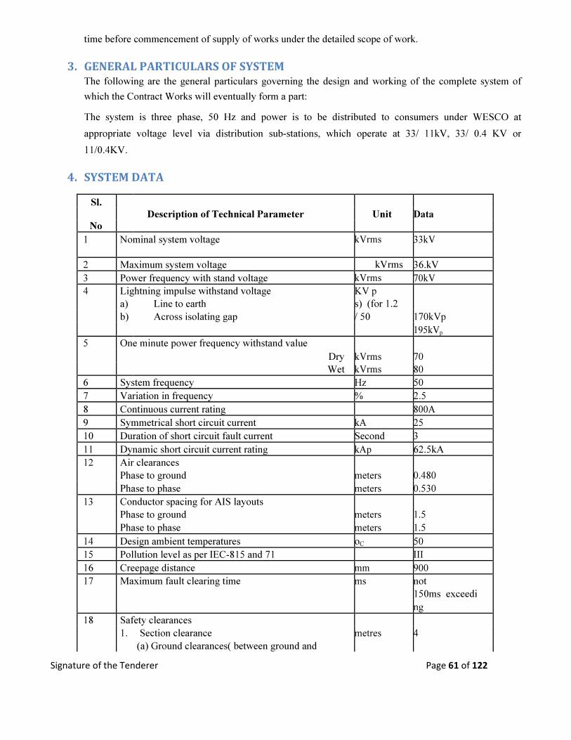
Signature of the Tenderer Page 61 of 122
time before commencement of supply of works under the detailed scope of work.
3. GENERAL PARTICULARS OF SYSTEM
The following are the general particulars governing the design and working of the complete system of
which the Contract Works will eventually form a part:
The system is three phase, 50 Hz and power is to be distributed to consumers under WESCO at
appropriate voltage level via distribution sub-stations, which operate at 33/ 11kV, 33/ 0.4 KV or
11/0.4KV.
4. SYSTEM DATA
Sl.
Description of Technical Parameter Unit Data
No
1 Nominal system voltage kVrms 33kV
2 Maximum system voltage kVrms 36.kV
3 Power frequency with stand voltage kVrms 70kV
4 Lightning impulse withstand voltage KV p
a) Line to earth s) (for 1.2
b) Across isolating gap / 50 170kVp
195kVp
5 One minute power frequency withstand value
Dry kVrms 70
Wet kVrms 80
6 System frequency Hz 50
7 Variation in frequency % 2.5
8 Continuous current rating 800A
9 Symmetrical short circuit current kA 25
10 Duration of short circuit fault current Second 3
11 Dynamic short circuit current rating kAp 62.5kA
12 Air clearances
Phase to ground meters 0.480
Phase to phase meters 0.530
13 Conductor spacing for AIS layouts
Phase to ground meters 1.5
Phase to phase meters 1.5
14 Design ambient temperatures oC 50
15 Pollution level as per IEC-815 and 71 III
16 Creepage distance mm 900
17 Maximum fault clearing time ms not
150ms exceedi
ng
18 Safety clearances
1. Section clearance metres 4
(a) Ground clearances( between ground and

Signature of the Tenderer Page 62 of 122
bottom most part of energised object) metres 4
(b) Horizontal clearance between the fence
and energised object
(c) Horizontal clearance between the road metres As per I.E.
centre line and energised part of the Rules
nearby equipment
19 Bay width metres 5.5
20 Height of bus equipment interconnection from ground metres 4
21 Height of strung busbar metres 5.5
5. Methodology
Description Data
Annual mean of maximum monthly 50
average temperature.
Annual mean of minimum monthly 5
temperature in oC
Average rain fall in mm 1500
Average thunder storms days per year
77d
ays
Design ambient temperature in oC 50
Maximum wind velocity in meter/sec. 50
Maximum relative humidity in % 100
Average relative humidity in % 85
Seismic co-efficient 0.06g Horizontal
0.01g Vertical

Signature of the Tenderer Page 63 of 122
6. GUARANTED TECHNICAL PARTICULARS
The Contract Works shall comply with the guaranteed technical particulars specified or quoted in the bid.
All plant and apparatus supplied under this Contract shall be to the approval of the Engg In-charge.
The Contractor shall be responsible for any discrepancies, errors or omissions in the particulars and
guarantees.
The Bidder for his own interest, shall establish the technical responsiveness of his bid, shall provide all
data in appropriate technical data sheets, general/ technical information, literature, and leaflets etc. along
with the bid.Compliance with Specification.
All apparatus should comply with this Specification. Any departures from the requirements of this
Specification shall be stated with reasons in the relevant Bid Proposal Schedules Bid will be considered
for evaluation if reasons shown are apparently justified. Unless brought out clearly in the technical
schedules, it will be presumed that the equipment is deemed to comply with the technical specification.
In the event of there being any inconsistency between the provisions of the conditions of contract and the
provisions of this Specification, in respect of commercial requirements, the provisions of the conditions
of contract shall take precedence for commercial matters and the provisions of this Specification shall
take precedence in respect of technical matters.
In case of inconsistency between technical specification (TS) & bid proposal sheet, (BPS) quantities of
various items as specified in the bid proposal sheet shall be considered for quoting. However the work
shall be executed as specified in the technical specification. Only brief description is given in the BPS &
the work shall be executed in line with the requirement given in the TS.
The manufacturer and places of manufacture, testing and inspection of the various portions of the
Contract Works shall be stated in the relevant Bid Proposal Schedules.
6.1. Erection at Site and accommodation
The Contractor shall provide, at his own cost and expense, all labors, plant and material necessary for
unloading and erection at the Site and shall be entirely responsible for its efficient and correct operation.
The Contractor shall be responsible for arranging and providing all living accommodation services and
amenities required by his employees.
6.2. Use of electrical energy
The Contractor shall arrange at his own cost and expense, any site supplies of electrical energy which he
may require for supplying power for heavy erection plant, welding plant or other tools, lighting and
testing purposes.
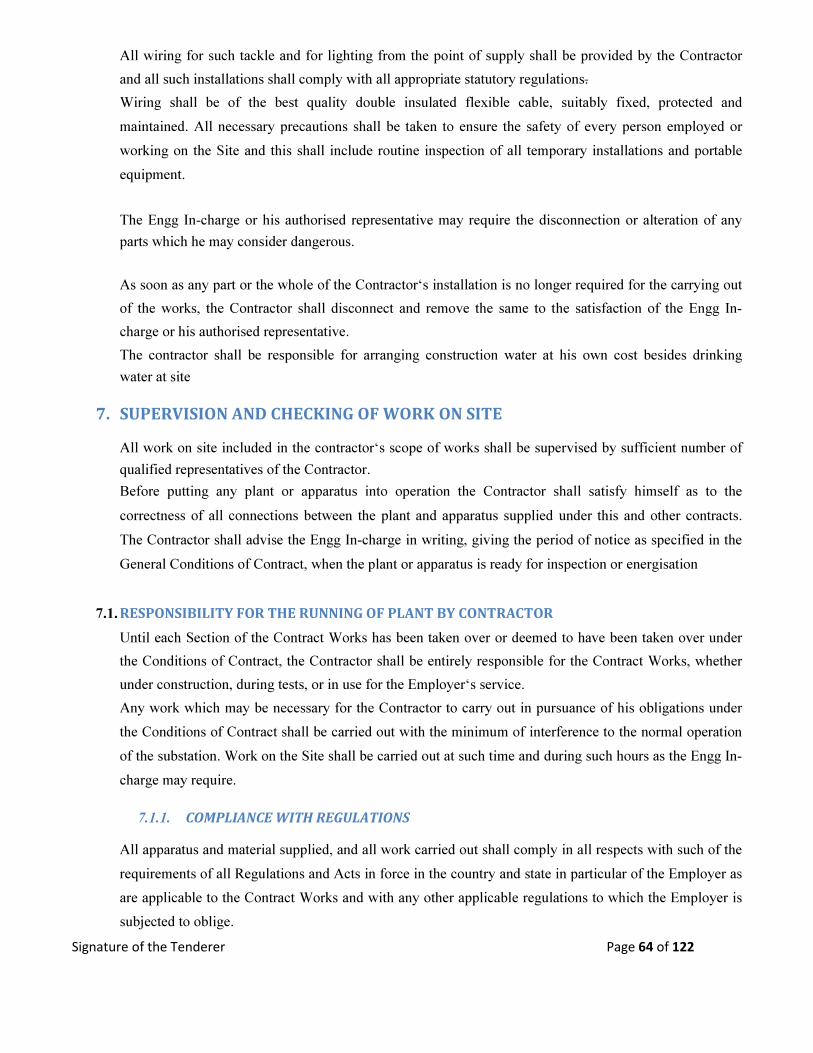
Signature of the Tenderer Page 64 of 122
All wiring for such tackle and for lighting from the point of supply shall be provided by the Contractor
and all such installations shall comply with all appropriate statutory regulations.
Wiring shall be of the best quality double insulated flexible cable, suitably fixed, protected and
maintained. All necessary precautions shall be taken to ensure the safety of every person employed or
working on the Site and this shall include routine inspection of all temporary installations and portable
equipment.
The Engg In-charge or his authorised representative may require the disconnection or alteration of any
parts which he may consider dangerous.
As soon as any part or the whole of the Contractor‘s installation is no longer required for the carrying out
of the works, the Contractor shall disconnect and remove the same to the satisfaction of the Engg In-
charge or his authorised representative.
The contractor shall be responsible for arranging construction water at his own cost besides drinking
water at site
7. SUPERVISION AND CHECKING OF WORK ON SITE
All work on site included in the contractor‘s scope of works shall be supervised by sufficient number of
qualified representatives of the Contractor.
Before putting any plant or apparatus into operation the Contractor shall satisfy himself as to the
correctness of all connections between the plant and apparatus supplied under this and other contracts.
The Contractor shall advise the Engg In-charge in writing, giving the period of notice as specified in the
General Conditions of Contract, when the plant or apparatus is ready for inspection or energisation
7.1. RESPONSIBILITY FOR THE RUNNING OF PLANT BY CONTRACTOR
Until each Section of the Contract Works has been taken over or deemed to have been taken over under
the Conditions of Contract, the Contractor shall be entirely responsible for the Contract Works, whether
under construction, during tests, or in use for the Employer‘s service.
Any work which may be necessary for the Contractor to carry out in pursuance of his obligations under
the Conditions of Contract shall be carried out with the minimum of interference to the normal operation
of the substation. Work on the Site shall be carried out at such time and during such hours as the Engg In-
charge may require.
7.1.1. COMPLIANCE WITH REGULATIONS
All apparatus and material supplied, and all work carried out shall comply in all respects with such of the
requirements of all Regulations and Acts in force in the country and state in particular of the Employer as
are applicable to the Contract Works and with any other applicable regulations to which the Employer is
subjected to oblige.

Signature of the Tenderer Page 65 of 122
The Contractor shall fully inform himself of the requirements of the local Laws, Regulations and rules in-
force in the State of Odisha, especially with respect to local employment laws, licensing requirements,
electrical safety rules and regulations, building regulations and planning procedures.
The Contractor shall be responsible for applying for all necessary licenses; including Electrical
Contractors License, Workman‘s Permits and Certificates of Competency for Supervisors, and local
government approvals required for the contract works and for the payment of all necessary fees associated
with such licenses and approvals.
Correspondence with the Electrical Inspector shall be conducted through the Engg In-charge, but the
Contractor shall provide all necessary information, regarding the contract works, as may be required by
the Electrical Inspector.
Additionally the Contractor shall also follow the adequate regulations on safety, environment, employee‘s
welfare etc. as stipulated under the relevant Clause of this section.
7.1.2. MAINTENANCE AND CLEARING OF SITE
The placing of materials and plant near the erection site prior to their being erected and installed shall be
done in a neat, tidy and safe manner. The Contractor shall at his own expense keep the site area allocated
to him and also the erection area of the Contract Works reasonably clean and shall remove all waste
material as it accumulates and as directed by the Engg In-charge from time to time.
8. Insurance
8.1. General
In addition to the conditions covered under the Clause titled insurance in the Special Conditions of
Contract, the following provisions will also apply to the portion of works to be done beyond the Suppliers
own or his sub-Contractors manufacturing Works.
8.2. Workmen's Compensation Insurance
This insurance shall protect the Contractor against all claims applicable under the Workmen‘s
Compensation Act, 1948 (Government of India). This policy shall also cover the Contractor against the
claims for injury, disability, disease or death of his or his sub-contractor's employees, which for any
reason are not covered under the Workman‘s
Compensation Act, 1948. The liabilities shall not be less than;
A. Workmen’s Compensation As per statutory provisions
B. Employee's liability
As per statutory provisions According to the Govt. rules.

Signature of the Tenderer Page 66 of 122
8.3. Work and Safety Regulations
The Contractor shall ensure safety of all the workmen, plant and equipment belonging to him or to others,
working at the Site. The Contractor shall also provide for all safety notices and safety equipment required by
the relevant legislation and deemed necessary by the Engg In-charge.
No claim due to such prohibition or towards additional safety provisions called for by him shall be entertained
by the Employer.
All equipment used in construction and erection by Contractor shall meet Indian or International Standards and
where such standards do not exist, the Contractor shall ensure these to be absolutely safe. All equipment shall
be strictly operated and maintained by the
Contractor in accordance with manufacturer’s operation manual and safety instructions and as per any existing
Guidelines/Rules in this regard.
Periodical examinations and all tests for all lifting and hoisting equipment and tackle shall be carried out in
accordance with the relevant provisions of Factories Act 1948, Indian Electricity (Supply) Act and associated
Laws/Rules in force, from time to time. A register of such examinations and tests shall be properly maintained by
the Contractor and will be promptly produced as and when desired by Engg In-charge . The Contractor shall provide suitable safety equipment of prescribed standard to all employees and workmen
according to the need, as may be directed by the Engg In-charge who will also have the right to examine such
safety equipment to determine it‘s suitability, reliability, acceptability and adaptability.
Where explosives are to be used, the same shall be used under the direct control and supervision of an expert,
experienced and qualified competent person, strictly in accordance with the Code of Practices/Rules framed under
Indian Explosives Act pertaining to handling, storage and use of explosive.
In case any accident occurs during the construction, erection or other associated activities undertaken by the
Contractor, thereby causing any minor or major or fatal injury to his employees due to any reason whatsoever, it
shall be the responsibility of the Contractor to promptly inform the same to the Engg In-charge/ Project Manager
and also to all the authorities envisaged under the applicable laws.
The Engg In-charge/ Project Manager /Owner shall have the right at his sole discretion to stop the work, if in his
opinion the work is being carried out in such a way as may cause accidents or endanger the safety of the persons
and/or equipment. In such cases, the Contractor shall be informed in writing about the nature of hazards and
possible injury/accident and he shall remove shortcomings immediately. The Contractor, after stopping the
specific work, can if felt necessary appeal against the order of stoppage of work to the owner within three days of
such stoppage of work and the decision of the owner in this respect shall be conclusive.
The Contractor shall not be entitled for any damages or compensation for stoppage of work due to safety reasons
and the period of such stoppage of work will not be taken as an extension of time for completion of work, nor will
it be the grounds for waiver of any part of suppliers liability for timely completion of the works.
The Contractor shall follow and comply with all Safety Rules, relevant provisions of applicable laws pertaining to

Signature of the Tenderer Page 67 of 122
the safety of workmen, employees, plant and equipment as may be prescribed from time to time without any
demur, protest or contest or reservation. In case of any conflict between statutory requirement and Safety Rules
referred above, the most stringent clause shall be applicable.
If the Contractor does not take all safety precautions and comply with Safety Rules as prescribed by the Engg In-
charge or as prescribed under the applicable law, to safeguard equipment, plant and personnel the Contractor shall
be responsible for payment of compensation to the Employer as per the schedule given below. If the Contractor does not prevent hazardous conditions which may cause injury to his own employees, employees
of other Contractors, or the Employer or any other person at Site or adjacent thereto, the Contractor shall be
responsible for payment of compensation to the Employer as per the following Schedule:
Fatal injury or Rs. 100,000/- per person Applicable for injury or death to
accident causing any person whomsoever.
death.
Major injuries or Rs. 20,000/- per person Applicable for injury or death to
accident causing 25% any person whomsoever.
or more permanent
disability.
• As per prevailing Govt. rules. Permanent disability shall have the same meaning as indicated in Workmen's Compensation Act. The
compensation mentioned above shall be in addition to the compensation payable to the workmen/employees
under the relevant provisions of the Workmen's Compensation Act and rules framed there under or any other
applicable law as applicable from time to time. In case the Employer is made to pay such compensation, the
Contractor will reimburse the Employer such amount(s) in addition to the compensation indicated above.
9. SUBMITTALS
9.1. Submittals required with the bid
The following shall be required in duplicate:
Completed technical data schedule;
Descriptive literature giving full technical details of equipment offered;
Type test certificates, where available, and sample routine test reports;
Deviations from this specification. Only deviations approved in writing before award of contract shall
be accepted;
9.2. Submittals required after contract award

Signature of the Tenderer Page 68 of 122
(i) Five copies of the program for production and testing.
(ii) Technical particulars
Within 15 days of contract award five bound folders with records of the technical particulars relating to
the equipment. Each folder shall contain the following information
General description of the equipment and all components, including brochures; Technical data schedule, with approved revisions; Calculations to substantiate choice of electrical and mechanical component size/ratings; Statement drawing attention to all exposed points in the equipment at which copper, aluminum or
aluminum alloy parts are in contact with or in close proximity to other metals and stating clearly what
protection is employed to prevent corrosion at each point; Detailed installation and commissioning instructions; At the final hold point for Project Manager Approval prior to delivery of the equipment the following
shall be submitted: Inspection and test reports carried out in the manufacturer's works; Installation and maintenance instructions.
9.3. Drawings
Within 15 days of contract commencement the Contractor shall submit, for approval by the Project
Manager, a schedule of the drawings to be produced detailing which are to be submitted for "Approval"
and which are to be submitted "For Information Only". The schedule shall also provide a programme of
drawing submission, for approval by the Project Manager that ensures that all drawings and calculations
are submitted within the period specified above.
All detail drawings submitted for approval shall be to scale not less than 1:20.
Lettering sizes and thickness of lettering and lines shall be selected so that if reduced by two stages to one
quarter of their size, the alphanumeric characters and lines are still perfectly legible so as to enable them
to be microfilmed.
For presentation of design drawings and circuit documents IEC Publication 617 or equivalent standards
for graphical symbols are to be followed.
9.4. APPROVAL PROCEDURE
The Contractor shall submit all drawings, documents and type test reports for approval in sufficient time to
permit modifications to be made if such are deemed necessary and re-submit them for approval without
delaying the initial deliveries or completion of the contract work. The Executive Engineer 's representative shall

Signature of the Tenderer Page 69 of 122
endeavor to return them within a period of 7days from the date of receipt.
Three copies of all drawings shall be submitted for approval and three copies for any subsequent revision. The
Executive Engineer reserves the right to request any further additional information that may be considered
necessary in order to fully review the drawings. If the Executive Engineer is satisfied with the drawing, one
copy will be returned to the Contractor marked with "Approved" stamp. If the Executive Engineer is not totally
satisfied with the drawing, then "Approved Subject to Comment" status will be given to it and a comment sheet
will be sent to the Contractor. If the drawing submitted does not comply with the requirements of the
specification then it will be given "Not Approved" status and a comment sheet will be sent to the Contractor. In
both these cases the Contractor will have to modify the drawing, update the revision column and resubmit for
final Approval. Following approval, twenty copies of the final drawings will be required by the Executive
Engineer.
The Contractor shall be responsible for any discrepancies or errors in or omissions from the drawings, whether
such drawings have been approved or not by the Executive Engineer. Approval given by the Executive
Engineer to any drawing shall not relieve the Contractor from his liability to complete contract works in
accordance with this specification and the condition of contract nor exonerate him from any of his guarantees.
10. ELECTRICAL WORKS
10.1. General
The following provisions shall supplement all the detailed technical specifications and requirements brought out
in accompanying Technical Specifications. The Contractor‘s proposal shall be based upon the use of equipment
and materials complying fully with the requirements specified herein. It is recognized that the Contractor may
have standardized on the use of certain components, materials, processes or procedures different to those
specified herein. Alternate proposals offering similar equipment based on the manufacturers standard practice
will also be considered, provided such proposals meet the specified design standard and performance
requirement and are acceptable to the Executive Engineer .
10.2. DESIGN AND STANDARDISATION The Works covered by the specification shall be designed, manufactured, built, tested and commissioned in
accordance with the Act, Rules, Laws and Regulations of India. The Equipment(s) shall also conform to the
requirements detailed in the referred standards, which shall form an integral part of the Specification, in addition
to meeting the specific requirements called for elsewhere in the Specification.
The Contract works shall be designed to facilitate inspection, cleaning and repairs, and for operation where
continuity of supply is the first consideration. Apparatus shall be designed to ensure satisfactory operation in all
atmospheric conditions prevailing at the Site(s) and during such sudden variation of load and voltage as may be
met with under working conditions on the system.

Signature of the Tenderer Page 70 of 122
The design shall incorporate all reasonable precautions and provisions for the safety of those concerned in the
operation and maintenance of the Contract Works and of associated works supplied under other contracts.
Where the Specification does not contain characteristics with reference to workmanship, equipment, materials
and components of the covered equipment, it is understood that the same must be new, of highest grade of the
best quality of their kind, conforming to best engineering practice and suitable for the purpose for which they are
intended.
The design of the Works shall be such that installation, future expansions, replacements and general maintenance
may be undertaken with a minimum of time and expense. Each
component shall be designed to be consistent with its duty and suitable factors of safety, subject to mutual
agreements and shall be used throughout the design. All joints and fastenings shall be so devised, constructed
and documented that the component parts shall be accurately positioned and restrained to fulfill their required
function.
All outdoor apparatus and fittings shall be designed so that water cannot accumulate at any point. Grease
lubricators shall be fitted with nipples and where necessary for accessibility, the nipples shall be placed at the
end of extension piping.
All water and oil pipe flanges shall be to IS 6392/BS 4504 or other equivalent standard, as regards both
dimensions and drilling, unless otherwise approved.
Cast iron shall not be used for chambers of oil filled apparatus or for any part of the equipment which is in
tension or subject to impact stresses.
Kiosks, cubicles and similar enclosed compartments shall be adequately ventilated to restrict condensation. All
contactor or relay coils and other parts shall be suitably protected against corrosion.
All apparatus shall be designed to obviate the risk of accidental short circuit due to animals, birds, insects, mites,
rodents or micro-organisms.
Corresponding parts shall be interchangeable. Where required by the Engg. Incharge (Divisional Eng.) the
Contractor shall demonstrate this quality.
10.3. Supervision strategy
The Contractor will provide supervisors with a minimum of five years experience of this type of work such that
they are able to supervise the quality and standards of the work without intervention by the Employer. The role
of the Employer will be to monitor and audit the quality of the work to ensure that it is of adequate standard and
that it is being safely and successfully managed.
10.3.1. Standards
Except where otherwise specified or implied, the Contract Works shall comply with the latest edition of the
relevant Indian Standards, International Electrotechnical Commission (IEC) standards and any other standards
mentioned in this Specification. The Contractor may submit for approval, equipment or materials conforming to
Signature of the Tenderer Page 71 of 122
technically equivalent National Standards. In such cases copies of the relevant Standards or part thereof, in the
English language shall be submitted with the Tender. In case of conflict the order of precedence shall be (1) IEC,
(2) IS and (3) other alternative standard.
Reference to a particular standard or recommendation in this Specification does not relieve the Contractor of the
necessity of providing the Contract Works complying with other relevant standards or recommendations.
The list of standards provided in the schedules of this Specification is not to be considered exhaustive and the
Contractor shall ensure that equipment supplied under this contract meets the requirements of the relevant
standard whether or not it is mentioned therein.
10.4. Language and system of units
The English language shall be used in all written communications between the Employer, the Engg. In charge
and the Contractor with respect to the services to be rendered and
with respect to all documents and drawings procured or prepared by the Contractor pertaining to the work, unless
otherwise agreed by the Employer.
It is required that danger plates, equipment designation labels or plates, instruction notices on plant and general
substation notices be written in English, Hindi and Oriya. Control switch and lamp labels, indicator lamp and
enunciator inscriptions shall be in English only.
The Contractor must furnish a schedule giving the English, Hindi and Oriya version of all labels, notices, etc., for
approval.
10.5. Employer's Supervision To eliminate delays and avoid disputes and litigation, it is agreed between the Parties to the Contracts that all
matters and questions shall be referred to the Employer and without prejudice the Contractor shall proceed to
comply with the Employer's decision.
The work shall be performed under the direction and supervision of the Engg. In charge . The scope of the duties
of the Engg. In charge pursuant to the contract, will include but not be limited to the following:
a) Interpretation of all the terms and conditions of these documents and specifications.
b) Review and interpretation of all the Contractors drawing, engineering data etc.
c) Inspect, accept or reject any equipment, material and work under Contract.
d) Issue certificate of acceptance and/or progressive payment and final payment certificates.
e) Review and suggest modification and improvements in completion schedules from time to time.
10.6. Testing and inspection
The Contractor shall carry out the tests stated in accordance with the conditions of this Specification, without
extra charge for such additional tests as in the opinion of the Executive Engineer are necessary to determine that
the Contract Works comply with this Specification. The tests shall be carried out generally in accordance with the
relevant
Signature of the Tenderer Page 72 of 122
IEC‘s or IS or equivalent standards. The specific details of testing and inspection are given in the appropriate
section of this Specification.
The Contractor shall submit Type Test Reports for all equipment being supplied by him for the Executive
Engineer ‘s approval.
All materials used shall be subjected to such routine tests as are customary in the manufacture of the types of
plant included in the Contract Works. These materials shall withstand satisfactorily all such tests.
All tests shall be carried out to the satisfaction of the Executive Engineer in his presence, at such reasonable
times as he may require, unless agreed otherwise. Not less than three weeks notice of all tests shall be given to the
Executive Engineer in order that he may be represented if he so desires. As many tests as possible shall be
arranged together. Six copies of the Contractor‘s test reports and test sheets shall be supplied to the Executive
Engineer for approval.
Measuring apparatus shall be approved by the Executive Engineer and if required shall be recalibrated at the
expense of the Contractor at an approved laboratory.
The Contractor shall be responsible for the proper testing of the work completed or plant or materials supplied by
a sub-contractor to the same extent as if the work, plant or materials were completed or supplied by the Contractor
himself.
All apparatus, instruments and connections required for the above tests shall be provided by the Contractor, but
the Executive Engineer may permit the use for the tests on site, any instruments and apparatus which may be
provided permanently on site as part of the contract works conditional upon the Contractor accepting liability for
any damage which may be sustained by such equipment during the test.
Any costs incurred by the Employer in connection with inspection and re-testing as a result of a failure of the
subject under test, or damage during transport, or erection on site before take-over by the Employer, shall be to
the account of the Contractor.
No inspection or lack of inspection or passing by the Executive Engineer of work, plant or materials, whether
carried out or supplied by the Contractor or sub-contractor, shall relieve the Contractor from his liability to
complete the Contract Works in accordance with the Contract or exonerate him from any of his guarantees.
10.7. Fire Precautions
All apparatus, connections and cabling shall be designed and arranged to minimise the risk of fire and any
damage which might be caused in the event of fire. When cabling is carried out as part of this Contract the
Contractor shall be responsible for sealing all holes in floors, walls, roofs etc. through which the cabling may
pass.
The work procedures that are to be used during the erection shall be those which minimise fire hazards to the

Signature of the Tenderer Page 73 of 122
maximum extent practicable. Combustible materials, combustible waste and rubbish shall be collected and
removed from the site at least once each day. Fuels, oils and volatile or flammable materials shall be stored away
from the construction site and equipment and material stores in appropriate safe containers.
All Contractors‘ supervisory personnel and at least ten percent all of workers shall be trained for fire-fighting and
shall be assigned specific fire protection duties. At least ten percent of all personnel assigned to site at any one
time shall be trained for fire fighting.
The contractor shall provide sufficient fire protection equipment of the types and sizes for the ware-houses,
office temporary structures, labour colony area etc. Access to such fire protection equipment shall be easy and
kept open at all time.
10.8. Packing, shipping and transport
The Contractor shall be responsible for the packing, loading and transport of the plant and equipment from the
place of manufacture, whether this is at his own works or those of any Contractor, to Site, and for off-loading at
site.
All apparatus and equipment shall be carefully packed for transport by air, sea, rail and road as necessary and in
such a manner that it is protected against tropical climate conditions and transport in rough terrain and cross
country road conditions. The method of packing shall provide complete protection to all apparatus and equipment
during transport and storage at site in heavy rain. The method of packing shall provide adequate protection to
main items of plant and those parts contained within and attached without, for transportation.
Precautions shall be taken to protect parts containing electrical insulation against the ingress of moisture.
All bright parts liable to rust shall receive a coat of anti-rusting composition and shall be suitably protected. The
machined face of all flanges shall be protected by means of a blank disc bolted to each face.
Where appropriate all parts shall be boxed in substantial crates or containers to facilitate handling in a safe and
secure manner. Each crate or container shall be marked clearly on the outside of the case to show ―TOP and
―BOTTOM positions with appropriate signs, and where the mass is bearing and the correct position for slings.
Each crate or container shall also be marked with the notation of the part or parts contained therein, contract
number and port of destination. It shall be the Contractor‘s responsibility to dispose of all such packing.
Any damage due to defective or insufficient packing shall be made good by the Contractor at his own expense and
within reasonable time when called upon by the Engg. In charge to do so. Four (4) copies of complete packing
lists showing the number, size, marks, mass and contents of each package shall be delivered to the Engg. In
charge immediately the material is dispatched.
The Contractor shall inform himself fully as to all relevant transport facilities and requirements and loading
gauges and ensure that the equipment as packed for transport shall conform to these limitations. The Contractor
shall also be responsible for verifying the access facilities specified.
Signature of the Tenderer Page 74 of 122
TECHNICAL SPECIFICATIONS
FOR
33/11 KV 5 MVA POWER TRANSFORMER
Signature of the Tenderer Page 75 of 122
1. TECHNICAL SPECIFICATION FOR 33/11KV 5 MVA POWER
TRANSFORMER
1.1. SCOPE
A. These specifications cover design, engineering, manufacturing, shop-testing, pre-delivery inspection,
packing & forwarding, loading at manufacturer's works, transportation, transit insurance, delivery & unloading at site/ stores of 33/11 KV Outdoor step down, ONAN cooled Power Transformers of 5 MV A, complete with all accessories/ fittings and spare parts as specified herein.
B. The Power Transformer shall conform in all respects to highest standards of engineering, design, workmanship, this specification and the latest revisions of relevant standards at the time of offer and the purchaser shall have the power to reject any material, which, in his Judgment, is not in full accordance therewith.
2. SPECIFIC TECHNICAL REQUIREMENTS
1 Rated MVA (ONAN rating) 5MVA
2 No. of Phases 3
3 Type of installation Outdoor
4 Frequency 50 Hz ( 5%)
5 Cooling medium Insulating Oil (ONAN)
6 Type of mounting On Wheels, Mounted on rails.
7 Rated voltage
a) High Voltage winding 33 KV
b) Low Voltage winding 11 KV
8 Highest continuous system voltage
a) Maximum system voltage ratio (HV/LV) 36 KV / 12 KV
b) Rated voltage ratio (HV/LV) 33 kV / 11 KV
9 No. of windings Two winding Transformers
10 Type of Cooling ONAN (Oil natural and Air natural)
11. MVA Rating corresponding to ONAN cooling 100% system
12 Method of connection :
HV Delta
LV Star
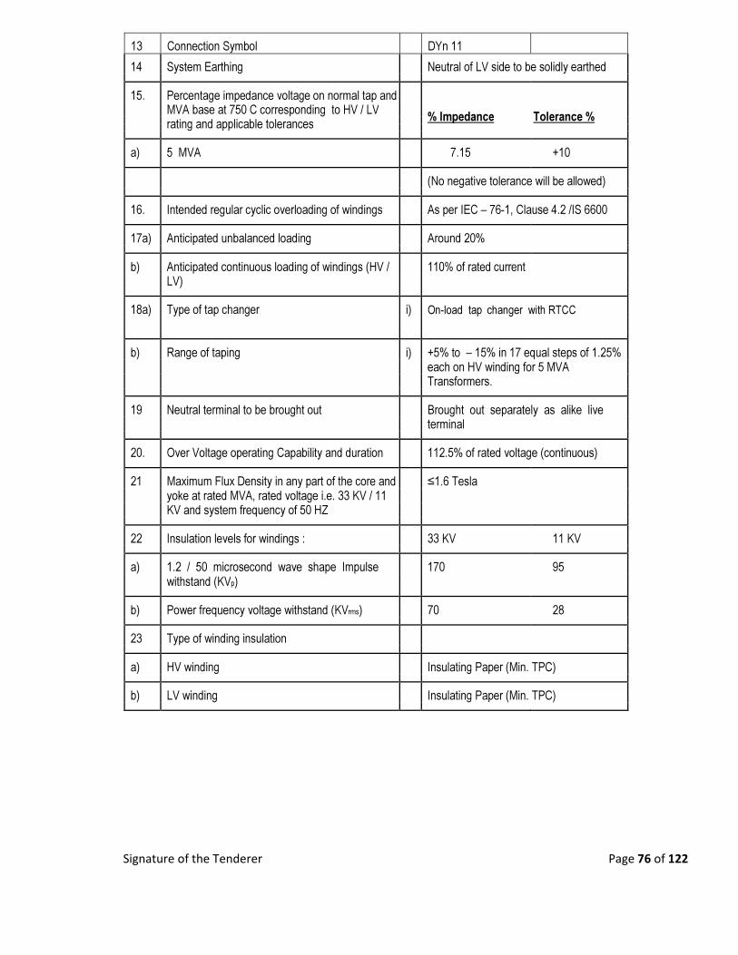
Signature of the Tenderer Page 76 of 122
13 Connection Symbol DYn 11
14 System Earthing Neutral of LV side to be solidly earthed
15. Percentage impedance voltage on normal tap and
MVA base at 750 C corresponding to HV / LV % Impedance Tolerance %
rating and applicable tolerances
a) 5 MVA 7.15 +10
(No negative tolerance will be allowed)
16. Intended regular cyclic overloading of windings As per IEC – 76-1, Clause 4.2 /IS 6600
17a) Anticipated unbalanced loading Around 20%
b) Anticipated continuous loading of windings (HV / 110% of rated current
LV)
18a) Type of tap changer i) On-load tap changer with RTCC
b) Range of taping i) +5% to – 15% in 17 equal steps of 1.25%
each on HV winding for 5 MVA
Transformers.
19 Neutral terminal to be brought out Brought out separately as alike live
terminal
20. Over Voltage operating Capability and duration 112.5% of rated voltage (continuous)
21 Maximum Flux Density in any part of the core and ≤1.6 Tesla
yoke at rated MVA, rated voltage i.e. 33 KV / 11
KV and system frequency of 50 HZ
22 Insulation levels for windings : 33 KV 11 KV
a) 1.2 / 50 microsecond wave shape Impulse 170 95
withstand (KVp)
b) Power frequency voltage withstand (KVrms) 70 28
23 Type of winding insulation
a) HV winding Insulating Paper (Min. TPC)
b) LV winding Insulating Paper (Min. TPC)
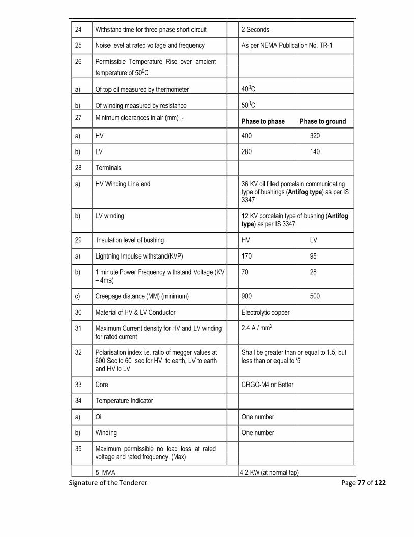
Signature of the Tenderer Page 77 of 122
24 Withstand time for three phase short circuit 2 Seconds
25 Noise level at rated voltage and frequency As per NEMA Publication No. TR-1
26 Permissible Temperature Rise over ambient
temperature of 500C
a) Of top oil measured by thermometer 400C
b) Of winding measured by resistance 500C
27 Minimum clearances in air (mm) :- Phase to phase Phase to ground
a) HV 400 320
b) LV 280 140
28 Terminals
a) HV Winding Line end 36 KV oil filled porcelain communicating
type of bushings (Antifog type) as per IS
3347
b) LV winding 12 KV porcelain type of bushing (Antifog
type) as per IS 3347
29 Insulation level of bushing HV LV
a) Lightning Impulse withstand(KVP) 170 95
b) 1 minute Power Frequency withstand Voltage (KV 70 28
– 4ms)
c) Creepage distance (MM) (minimum) 900 500
30 Material of HV & LV Conductor Electrolytic copper
31 Maximum Current density for HV and LV winding 2.4 A / mm2
for rated current
32 Polarisation index i.e. ratio of megger values at Shall be greater than or equal to 1.5, but
600 Sec to 60 sec for HV to earth, LV to earth less than or equal to ‘5’
and HV to LV
33 Core CRGO-M4 or Better
34 Temperature Indicator
a) Oil One number
b) Winding One number
35 Maximum permissible no load loss at rated
voltage and rated frequency. (Max)
5 MVA 4.2 KW (at normal tap)
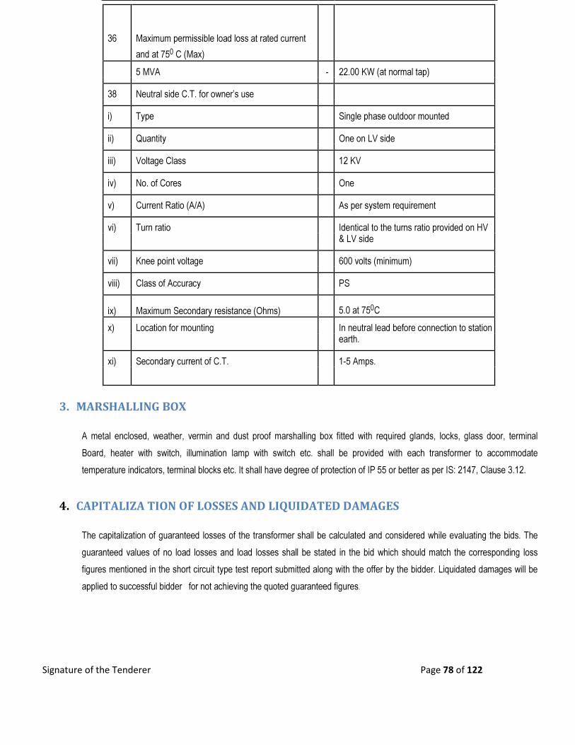
Signature of the Tenderer Page 78 of 122
3. MARSHALLING BOX
A metal enclosed, weather, vermin and dust proof marshalling box fitted with required glands, locks, glass door, terminal
Board, heater with switch, illumination lamp with switch etc. shall be provided with each transformer to accommodate
temperature indicators, terminal blocks etc. It shall have degree of protection of IP 55 or better as per IS: 2147, Clause 3.12.
4. CAPITALIZA TION OF LOSSES AND LIQUIDATED DAMAGES
The capitalization of guaranteed losses of the transformer shall be calculated and considered while evaluating the bids. The
guaranteed values of no load losses and load losses shall be stated in the bid which should match the corresponding loss
figures mentioned in the short circuit type test report submitted along with the offer by the bidder. Liquidated damages will be
applied to successful bidder for not achieving the quoted guaranteed figures.
36 Maximum permissible load loss at rated current
and at 750 C (Max)
5 MVA - 22.00 KW (at normal tap)
38 Neutral side C.T. for owner’s use
i) Type Single phase outdoor mounted
ii) Quantity One on LV side
iii) Voltage Class 12 KV
iv) No. of Cores One
v) Current Ratio (A/A) As per system requirement
vi) Turn ratio Identical to the turns ratio provided on HV & LV side
vii) Knee point voltage 600 volts (minimum)
viii) Class of Accuracy PS
ix) Maximum Secondary resistance (Ohms) 5.0 at 750C
x) Location for mounting In neutral lead before connection to station earth.
xi) Secondary current of C.T. 1-5 Amps.

Signature of the Tenderer Page 79 of 122
5. PERFORMANCE
a. Transformer shall be capable of withstanding for two seconds without damage to any external short circuit, with the short
circuit MV A available at the terminals.
b. The maximum flux density in any part of the core and yoke at rated MVA Voltage and frequency shall be 1.6 Tesla (maximum).
c. Transformer shall under exceptional circumstances due to sudden disconnection of the load, be capable of operating at
the voltage approximately 25% above normal rated voltage for a period of not exceeding one minute and 40% above normal for a period of 5 seconds.
d. The transformer may be operated continuously without danger on any particular tapping at the rated MVA 12.5% of the
voltage corresponding to the tapping.
e. The thermal ability to withstand short circuit shall be demonstrated by calculation.
f. Transformer shall be capable of withstanding thermal and mechanical stress caused by any symmetrical and asymmetrical faults on any winding.
6. AUXILIARY POWER SUPPLIES
The following power supplies shall be available at site:
g. AC .3-phase, 400 volts, 50Hz. Earthed
h. AC 1- phase, 230 volts, 50Hz. Earthed
7. DRAWINGS/ DOCUMENTS INCORPORATING THE FOLLOWING PARTICULARS
SHALL BE SUBMITTED ALONG WITH THE TECHNICAL BID
a) General outline drawing showing shipping dimensions and overall dimensions, net weights and shipping weights, quality of insulating oil, spacing of wheels in either direction of motion, location of coolers, marshalling box and tap changers etc.
b) Assembly drawings of core, windings etc. and weights of main components / parts.
c) Height of center line on HV and LV connectors of transformers from the rail top level.
d) Dimensions of the largest part to be transported.
e) GA drawings / details of various types of bushing
f) Tap changer and Name Plate diagram
g) List of Testing & Measuring Instruments along with calibration details.
h) Illustrative & descriptive literature of the Transformer.
i) Maintenance and Operating Instructions.
8. MISCELLANEOUS :
Padlocks along with duplicate keys for various valves, marshalling box etc. shall be supplied by the supplier, wherever locking arrangement is provided.
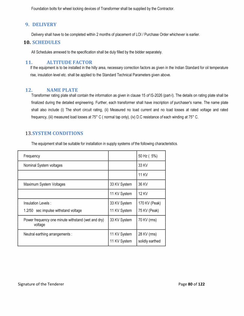
Signature of the Tenderer Page 80 of 122
Foundation bolts for wheel locking devices of Transformer shall be supplied by the Contractor.
9. DELIVERY
Delivery shall have to be completed within 2 months of placement of LOI / Purchase Order whichever is earlier.
10. SCHEDULES
All Schedules annexed to the specification shall be duly filled by the bidder separately.
11. ALTITUDE FACTOR If the equipment is to be installed in the hilly area, necessary correction factors as given in the Indian Standard for oil temperature
rise, insulation level etc. shall be applied to the Standard Technical Parameters given above.
12. NAME PLATE Transformer rating plate shall contain the information as given in clause 15 of IS-2026 (part-I). The details on rating plate shall be
finalized during the detailed engineering. Further, each transformer shall have inscription of purchaser's name. The name plate
shall also include (i) The short circuit rating, (ii) Measured no load current and no load losses at rated voltage and rated
frequency, (iii) measured load losses at 75° C ( normal tap only), (iv) D.C resistance of each winding at 75° C.
13. SYSTEM CONDITIONS
The equipment shall be suitable for installation in supply systems of the following characteristics.
Frequency 50 Hz ( 5%)
Nominal System voltages 33 KV
11 KV
Maximum System Voltages 33 KV System 36 KV
11 KV System 12 KV
Insulation Levels : 33 KV System 170 KV (Peak)
1.2/50 sec impulse withstand voltage 11 KV System 75 KV (Peak)
Power frequency one minute withstand (wet and dry) 33 KV System 70 KV (rms) voltage
Neutral earthing arrangements : 11 KV System 28 KV (rms)
11 KV System solidly earthed
Signature of the Tenderer Page 81 of 122
14. DRAWINGS TO BE SUBMITTED AFTER AWARD OF CONTRACT
a) The manufacturer shall furnish, within fifteen days after issuing of Letter of Award. Six copies each of the following
drawings/documents incorporating the transformer rating for approval.
Detailed overall general arrangement drawing showing front and side elevations and plan of the transformer and all accessories
including radiators and external features with details of dimensions, spacing of wheels in either direction of motion, net weights and
shipping weights, crane lift for un-tanking, size of lugs and eyes, bushing lifting dimensions, clearances between HV and L.V
terminals and ground, quantity of insulating oil etc.
a. Assembly drawings of core and winding and weights of main components / parts.
b. Foundation plan showing loading on each wheel land jacking points with respect to center line of transformer.
c. GA drawings details of bushing and terminal connectors.
d. Name plate drawing with terminal marking and connection diagrams.
e. Wheel locking arrangement drawing.
f. Transportation dimensions drawings.
g. Magnetization characteristic curves of PS class neutral and phase side current transformers, if applicable.
h. Interconnection diagrams.
i. Over fluxing withstand time characteristic of transformer.
j. GA drawing of marshalling box.
k. Control scheme/wiring diagram of marshalling box.
Signature of the Tenderer Page 82 of 122
TECHNICAL SPECIFICATION
FOR
33KV OUTDOOR VACUUM CIRCUIT
BREAKERS
Signature of the Tenderer Page 83 of 122
15. SCOPE
a) This specification covers design, engineering, manufacture, testing, inspection before dispatch packing,
forwarding, transportation, insurance during transit, delivery to site/ stores of 33KV Outdoor Vacuum
Circuit Breakers for use the 33/11KV primary substations under the distribution networks of WECO.
b) All vacuum circuit breakers must be manufactured by ISO 9000 certified Organization and shall have
been type tested at CPRI or any NABL Accredited laboratory/PHELA/KERI/KEMA/CESI within five
years as on the date of bid opening and in satisfactory operation for a period not less than three years.
The Bidder shall demonstrate compliance with this requirement by supplying with the bid, copies of the
type test certificates together with performance certificates from purchasers/ users.
c) The scope also includes the circuit breaker and current and potential transformers, supporting structures,
operating mechanism, local/ remote control cabinet, relay control panel, foundation bolts, all the
accessories and auxiliary equipment mandatory spares and special tools for satisfactory installation and
operation.
d) The circuit breakers shall conform in all respects to the highest standards of engineering, design,
workmanship, this specification and the latest revisions of relevant standards at the time of offer and the
purchaser shall have the power to reject any work or materials, which, in his judgment, is not in full
accordance therewith.
16. REQUIREMENTS
The circuit breakers to be supplied against this specification shall be required to control the primary side
of 33/11 KV power transformers in the primary sub-stations (incoming 33KV feeders) or Bus coupler or
the outgoing feeders in these sub-stations. The circuit breakers shall be suitable for 3 phase 50Hz solidly
grounded neutral system and shall have normal current carrying capacity and symmetrical short circuit
current breaking capability as mentioned hereunder.
The required 33KV Vacuum Circuit Breakers suitable for outdoor installations are to be quoted by
Manufacturers only with a valid ISO 9000 certification.
17. BASIC TECHNICAL REQUIREMENTS:
The vacuum circuit breakers are required to meet the following basic technical requirements. (Reference
standards IEC:56, IEC: 62271-100&200, IS:13118 and associated standards listed in this specification.
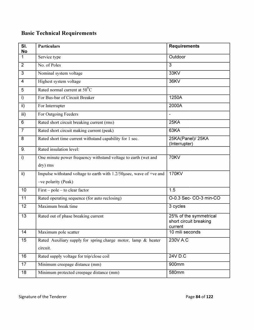
Signature of the Tenderer Page 84 of 122
Basic Technical Requirements
Sl. Particulars Requirements No
1 Service type Outdoor
2 No. of Poles 3
3 Nominal system voltage 33KV
4 Highest system voltage 36KV
5 Rated normal current at 500C
i) For Bus-bar of Circuit Breaker 1250A
ii) For Interrupter 2000A
iii) For Outgoing Feeders -
6 Rated short circuit breaking current (rms) 25KA
7 Rated short circuit making current (peak) 63KA
8 Rated short time current withstand capability for 1 sec. 25KA(Panel)/ 25KA (Interrupter) 9. Rated insulation level:
i) One minute power frequency withstand voltage to earth (wet and 70KV
dry) rms
ii) Impulse withstand voltage to earth with 1.2/50µsec, wave of +ve and 170KV
–ve polarity (Peak)
10 First – pole – to clear factor 1.5
11 Rated operating sequence (for auto reclosing) O-0.3 Sec- CO-3 min-CO
12 Maximum break time 3 cycles
13 Rated out of phase breaking current 25% of the symmetrical short circuit breaking current
14 Maximum pole scatter 10 mili seconds
15 Rated Auxiliary supply for spring charge motor, lamp & heater 230V A.C
circuit.
16 Rated supply voltage for trip/close coil 24V D.C
17 Minimum creepage distance (mm) 900mm
18 Minimum protected creepage distance (mm) 580mm

Signature of the Tenderer Page 85 of 122
18. 33 KV VACUUM CIRCUIT BREAKERS
18.1 General
The circuit breakers shall be structure mounted open type with vacuum as interrupting media incorporating
separate interrupters of 2000 A rating for each phase mounted on single frame. There shall be a common
drive mechanism actuating the interrupters, which must work in synchronism. These breakers shall be
provided with suitable local control while provision shall be made for remote control.
The circuit breakers shall be fitted with spring mechanism. The inherent design of these circuit breakers shall
be such that they shall satisfactorily perform all test duties and interrupt out-of-phase current and produce
very low over voltage (<2.0p.u.) on all switching circuits, capacitive and inductive to IEC:56, IS:13118 and
other associated standards mentioned in the clause of this specification.
The terminal pads shall have aluminum alloy with smooth finishing. The design of the circuit breakers shall
be such that inspection and replacement of contracts, coils, vacuum bottles and any worn or damaged
components can be carried out quickly and this ease. The contract gaps shall be adjustable to allow for wear.
The mechanism and the connected interrupters shall satisfy the mechanical endurance requirements of
IEC:56, IS:13118 and all additional requirements specified herein. 18.2 Porcelain Insulator
External parts of the circuit breakers, which are under continuous electrical stress, shall be of hollow
porcelain. The creepage and flashover distance of the insulators shall be dimensioned and the type and profile
designed in accordance with IEC:815 or IS: 13134 and shall be suitable for the worst environmental
conditions specified in this specification. The creepage distance across the interrupting chambers shall suite
the outdoor service conditions mentioned in the relevant standards for heavily polluted atmosphere and shall
be not less than 900 mm with protected creepage distance 50 percent of the total. Internal surfaces of hollow
insulators shall also be glazed. The insulators shall comply with IS:5621 and tested in accordance with
IEC:233. All porcelain whether, used on the interrupting chamber or on the support insulator shall have the
following properties:Higher strength, homogeneity, uniform glaze, free from cavities and other flaws and
high quality uniform finish porcelain components and shall withstand the maximum expected static and
dynamic loads to which the circuit breakers may be subjected during their service life.
18.2 Interrupting media 18.3.1 Vacuum:
In vacuum circuit breakers, facilities shall be provided for monitoring the contract erosion and any change in
contact gap. The vacuum bottles shall be easily replaceable on site and the mechanism shall be conveniently
adjustable to permit resetting the contact gap.
The vacuum circuit breaker poles shall be sealed to prevent contamination of the spaces surrounding the
interrupters. The Bidder shall demonstrate how this is achieved by supplying technical details with the bid.
Signature of the Tenderer Page 86 of 122
18.3.2 Auxiliary contracts
12 auxiliary contacts (6N.O. + 6N.C.) of 24 Volt D.C grade and 10 amps DC rating shall be provided in each
circuit breaker. 18.3.3 Indication
A mechanically operated circuit breaker position indicator of non corroding material shall be provided in a location
visible from the operating side of the breaker without the necessity to open the mechanism door. The word „OFF in
white letter on green background shall be used to indicate that the breaker is in the opening position and the word
„ON in white letters on a red background to indicate that the breaker is in the closed position. The drive for the
device shall be positive in both directions and provision shall be made for local and remote electrical indication.
Indication of spring charging condition shall be provided as mentioned in this specification. Mechanical counters to
record the number of closing operations shall be provided for each circuit breaker mechanism. 18.3.4 Operation and controls
The breaker shall normally be operated by remote electrical control with electrical tripping by shunt trip coil.
Provision shall be made for local electrical operation and mechanical operation. The following facilities shall
be provided in the circuit breaker local control cabinet:
• LOCAL/ REMOTE selector switch of stay put type. The selection of „local operation shall inhibit the
operation of the breaker from any remote source.
• ON/NEUTRAL/ OFF control switch or ON and OFF push buttons. The push buttons shall be
momentary contract type with rear terminal connections. The close push button shall be of green
colour and the open push button red colour.
• MECHANICAL EMERGENCY TRIP DEVICE: suitable for manual operation in the event of failure
of electrical supplies. The device shall be accessible without opening any access doors and distinctly
labeled. It shall be shrouded and protected against inadvertent operation.
• Means shall be provided for manual operation of these circuit breakers during failure of auxiliary
power in addition to electrical operation.
• Means shall be provided to prevent the mechanism from responding to a close signal when the trip coil
is energized or to reclosing from a sustained close signal either opening due to a trip signal or failure to
hold in the closed position.
The circuit breaker shall be able to perform 10,000 operating cycles at no load in accordancewith
IEC:17A/474/CD for circuit breakers for auto reclosing duties.

Signature of the Tenderer Page 87 of 122
19. CURRENT TRANSFORMERS
Current transformers, three per circuit breaker, shall be of outdoor, single phase oil immersed dead tank type
and shall comply with IEC:185 and IS:2705, suitable for operation in hot and humid atmospheric conditions
described in service condition. They shall be mounted on the bracket. The CT tank should be Hot Dip
galvanized as per relevant ISS to prevent corrosion of all exposed metal parts.
19.1 Core
High grade non- ageing cold rolled grain oriented (CRGO M4 or better grade) silicon steel of low hysteresis
loss and permeability shall be used for the core so as to ensure specified accuracy at both normal and over
currents. The flux density shall be limited to ensure that there is no saturation during normal service.
The instrument security factor of the core shall be low enough so as not to cause damage to the instruments
in the event of maximum short circuit current.
19.2 Windings
The secondary windings shall be made of electrolytic copper with suitable insulation. The conductor shall be
of adequate cross- section so as to limit the temperature rise even during short circuit conditions. The
insulation of windings and connections shall be free from composition liable to soften coze, shrink or
collapse during service.
Polarity shall be indelibly marked on each current transformer and at the lead and termination at associated
terminal blocks. CTs with multi ratio winding shall be clearly tabulated to show the connections required for
different ratios. Similar numbers shall be marked on terminal block arrangement and wiring diagram. Apart
from the above marking and those to be provided as per IEC 185 or IS 2705, other markings shall be
provided in consultation with owner.
The continuous current rating of the primary winding shall be one hundred and fifty percent of the normal
rated current. Secondary windings of current transformers shall be used for metering, instrumentation and
protection and shall be rated for continuous current of one hundred and fifty percent of normal rated current
of primary winding.
Secondary winding stud should be 6mm dia of length 15 mm. TB should be stud type with 3 nos. of nuts
(min). The horizontal distance from studs should be 1.5 times the outside circular – dia of the nuts. Test tap
should be with shorting arrangement.
19.3 Construction
The current transformer enclosures shall be made of high quality steel and shall be hot dip galvanized and
shall be able to withstand and stresses occurring during transportation and the terminal and mechanical
stresses resulting from maximum short circuit current in service. The primary winding and terminals shall be
in a tank and supported by a hollow porcelain insulator. The secondary connection shall be conducted through
the hollow insulator and terminated in a terminal box mounted on the base plate.
Signature of the Tenderer Page 88 of 122
19.4 Hermetic sealing
Each current transformer shall be supplied filled with insulating oil complying with IEC: 296 or IS: 335 and
shall be hermetically sealed to prevent atmosphere coming in contact with oil, avoiding frequent filtration and
change of oil. Nitrogen or any oil inert gas above the oil level shall be provided to permit expansion and
contraction of oil without any contract with the atmosphere.
The current transformers shall have provision for draining and re-filling insulation oil after drying.
19.5 Insulating oil
The current transformer shall be complete with new insulating oil. The quantity of insulating oil for first
filling of the equipment and complete specification of oil proposed to be used shall be stated in the bid. The
oil shall conform to the requirements of latest issue of IEC: 296 or IS: 335.
19.6 Fittings and accessories
Fittings and accessories listed below shall be supplied with each current transformer:
• Oil level gauge;
• Oil filling hole and cap;
• Pressure relief device;
• HV terminal connectors;
• Two earthing terminals and strips with necessary nut, bolts and washers;
• Name and rating plate;
• Terminal box with LV terminal connections;
• Mounting nuts, bolts and washers;
Any other fittings deemed essential by the Supplier shall also be supplied with each current transformer.
The oil level gauge shall be mounted in such a way that the oil level can be clearly seen from ground level.
A dust, vermin and weather proof terminal box shall be provided at the lower end of the current transformer
for terminating the secondary windings. The box shall have a bolted cover plate complete with gaskets. The terminal
box shall have terminal blocks, cable gland plate and cable glands with shrouds suitable for different sizes of PVC
insulated control cables 650/1100V grade as per IEC:227 or IS:1554. The terminal blocks shall have covering of
molded insulation materials complete with brass studs, washers, nuts and lock nuts suitable for termination of
2X2.5mm2 wires. The termination shall be made by crimping lugs or bare wire with insulating sleeves at ends.
The terminal box enclosure shall have protection as per class IP 55 as defined in IEC: 529 or IS: 13947.
Signature of the Tenderer Page 89 of 122
19.7 CT Junction Box/Console Box
Each set of 3 current transformers for three phases shall be provided with a common junction box mounted on
the circuit breaker supporting structure at a convenient position to accommodate the secondary wire of CT
and other control cables of Purchaser. Separate terminals for testing the relays and instruments and short
circuiting of each current transformer secondary wires shall be provided in it. The junction box enclosure
shall have the same protection features as for the terminal box. It shall be provided with terminal blocks,
gland plates and glands suitable for different sizes of cables. Facilities shall be provided for earthing the CT
secondary wires in the junction box.
19.7 Hollow porcelain insulators
The insulators of the current transformers shall conform to latest edition of IS: 5621 and shall be subjected to
and successfully pass the tests listed in this standard and in IEC: 233. The hollow porcelain insulators shall be
brown glazed and shall meet the requirements indicated in this specification. The insulators shall be cemented
with Portland cement to the flanges resulting in high mechanical, tensile and breaking strength.
19.8 Insulation level
The current transformers shall be designed to withstand impulse test voltages and power frequency test
voltages as specified in this specification.
19.9 Terminal connections
The CTs shall be provided with bi-metallic solder less clamp and rigid type terminal connectors on the top
tank for connection to the HV terminals. The other requirements shall be same as for the terminal connectors
of the circuit breaker described in this specification. They shall be universal type suitable for both horizontal
and vertical connections.
Two earthing terminals complete with necessary hardware shall be provided on each CT for connecting
to earth continuity conductor to be provided. The earthing terminals shall be identified by means of
appropriate symbol marked in a legible and indelible manner adjacent to the terminals. The terminals
shall be adequately sized to meet the full earth fault current envisaged.
19.10 Basic technical requirement
Ratings: The CTs shall conform to the following ratings and other particulars of the circuit breakers:
Signature of the Tenderer Page 90 of 122
Technical Requirements –
For 3 Core & 2 Core CT

Signature of the Tenderer Page 91 of 122
Technical Requirements – For 3 Core CT
Sl. Particulars Requirements
No
1 Function To control the Primary side of 33/11 KV power
transformers of ratings between 1.6MVA and 10MVA in
primary substations.
2 Requirement Core-1:Instrumentation and Metering
Core-2:Combined over current and earth fault protection
Core-3:Differential Protection
3 Transformation Ratio 200-100-50/1-1-1 A
4 Rated Burden (VA) Core:1:15
Core:2:15
Core:3:PS
5 Class of Accuracy Core- 1:0.5
Core- 2:5P
Core-3: PS
6 Instrument Security Factor Core- 1 < 5
7 Accuracy Limit Factor Core-2 : 20
Core-3 : 20
8 Rated Voltage 36KV
9 Short Time Rating 25KA rms for 3 seconds
10 Creepage distance Protected 900mm minimum
creepage distance
450mm minimum
11 Insulation Level:
-Impulse Voltage1.2/50µs
170KV
wave withstand level 70KV
-Power frequency 1 min
voltage withstand level
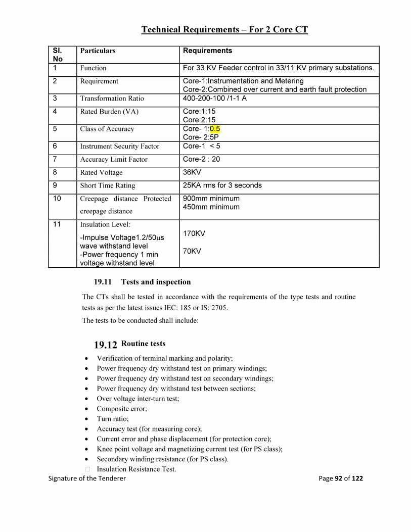
Signature of the Tenderer Page 92 of 122
Technical Requirements – For 2 Core CT
Sl. Particulars Requirements
No
1 Function For 33 KV Feeder control in 33/11 KV primary substations.
2 Requirement Core-1:Instrumentation and Metering
Core-2:Combined over current and earth fault protection
3 Transformation Ratio 400-200-100 /1-1 A
4 Rated Burden (VA) Core:1:15
Core:2:15
5 Class of Accuracy Core- 1:0.5
Core- 2:5P
6 Instrument Security Factor Core-1 < 5
7 Accuracy Limit Factor Core-2 : 20
8 Rated Voltage 36KV
9 Short Time Rating 25KA rms for 3 seconds
10 Creepage distance Protected 900mm minimum
creepage distance
450mm minimum
11 Insulation Level:
-Impulse Voltage1.2/50µs
170KV
wave withstand level 70KV
-Power frequency 1 min
voltage withstand level
19.11 Tests and inspection
The CTs shall be tested in accordance with the requirements of the type tests and routine
tests as per the latest issues IEC: 185 or IS: 2705.
The tests to be conducted shall include:
19.12 Routine tests • Verification of terminal marking and polarity; • Power frequency dry withstand test on primary windings; • Power frequency dry withstand test on secondary windings; • Power frequency dry withstand test between sections; • Over voltage inter-turn test; • Composite error; • Turn ratio; • Accuracy test (for measuring core); • Current error and phase displacement (for protection core); • Knee point voltage and magnetizing current test (for PS class); • Secondary winding resistance (for PS class). X Insulation Resistance Test.

Signature of the Tenderer Page 93 of 122
POTENTIAL TRANSFORMER

Signature of the Tenderer Page 94 of 122
20. POTENTIAL TRANSFORMER
20.1 BASIC TECHNICAL REQIREMENTS
The 33KV outdoor voltage transformers are required to meet the following basic technical
requirements (Reference standards: IEC: 186, IS: 3156 and associated standards listed in the
specification):
Sl. Particulars Requirements
No
1 Type Single phase
2 Nominal system voltage, phase to phase 33KV
3 Application Instrumentation, Metering and Protection
4 Number of secondary windings 1
5 Rated normal burden* 200VA
6 Rated primary voltage 33KV/ √3
7 Rated secondary voltage 110V/ √3
8 Class of accuracy 0.5
9 Rated insulation level: (Primary winding) (Phase
to earth)
i) One minute power frequency withstand voltage to 70KV
earth (wet and dry) rms
ii) Impulse withstand voltage to earth with 1.2/50 170KV
µsec wave of +ve and –ve polarity (peak)
10 One minute power frequency withstand voltage of
secondary winding (rms)
i) Between phase to earth 3KV
ii) Between sections 3KV
11 Rated voltage factor
i) Continuous 1.2
ii) For 30 seconds 1.5
12 Creepage distance to earth in mm per KV of 25
highest phase to phase system voltage
* The burden indicated is the minimum acceptable to the Purchaser. The Supplier shall
ensure that the rated output of the voltage transformers is adequate to meet at least 120
percent of the connected load (burden).

Signature of the Tenderer Page 95 of 122
20.2 GENERAL
The voltage transformers to be supplied under this specification shall be of outdoor, single
phase dead tank double wound, oil immersed type, complying with IEC:185 and IS:3156
suitable for operation in hot and humid atmospheric conditions described in this document. To
prevent corrosion of the exposed surfaces, the tank should be not dip galvanized. They shall
have separate HV and LV windings and shall be suitable for use as bus VTs in 33/11KV
primary substations.
20.3 Duty requirement
33KV Voltage transformer for all the indicating instruments and measuring meters in the
primary substation on 33KV side.
20.4 Porcelain Insulator
External parts of the voltage transformers which are under continuous electrical stress shall be of
hollow porcelain insulators complying with latest edition of IS:6521 tested as per IEC:233. The
creepage and flashover distance of the insulators shall be dimensioned and the type and profile
designed in accordance with IEC:815 or IS:13134 and shall be suitable for the worst
environmental conditions for heavily polluted atmosphere and shall be not less than 25mm per KV
of highest phase to phase system voltage with protected creepage distance minimum 50 percent of
the total. Internal surfaces of hollow insulators shall also be glazed.
The insulators shall be cemented with Portland cement to the flanges resulting in high
mechanical, tensile and breaking strength.
All porcelain used on the voltage transformers shall have the following properties high strength,
homogeneity, uniform glaze, free from cavities and other flaws and a high quality uniform finish
porcelain components shall withstand the maximum expected static and dynamic loads to which
the voltage transformers may be subjected during their service life.
The insulation of the hollow porcelain insulators shall be coordinated with that of the voltage
transformers to ensure that any flash over occurs only externally.
20.5 Core
High grade non-ageing cold rolled grain oriented silicone steel of low hysteresis loss and
permeability shall be used for core so as to ensure accuracy at both normal and or over Voltages.
The flux density shall be limited to 1.6 Tesla at normal voltage and frequency. There shall be no
saturation at any stage during operation.
Signature of the Tenderer Page 96 of 122
The instrument security factor of the core shall be low enough so as not to cause damage to the
instruments in the event of maximum short circuit current or over voltages.
20.6 Windings
The primary and secondary windings shall be electrolytic copper of high purity and conductivity
and covered with double paper insulation. The conductor shall be of adequate cross-section so as
to limit the temperature rise even during maximum over voltages.
The insulation of windings and connections shall be free from composition liable to soften, ooze,
shrink or collapse during service.
The current rating of the primary winding shall be one hundred and fifty percent of the normal
rated burden and the windings shall be suitable to withstand continuously the maximum system
voltage.
The secondary windings of the voltage transformers shall also be suitable for continuous over
voltage corresponding to the maximum system voltage at the primary winding. The winding
supports shall be suitably reinforced to withstand normal handling and the thermal and dynamic
stresses during operation without damage.
The voltage transformer secondary circuits will be taken out to form the star point and earthed at
one point outside the voltage transformers.
Both primary and secondary winding terminals shall be clearly and indelibly marked to show polarity in
accordance with IEC:186. The connections required for different secondary windings in case of multi-
winding voltage transformers shall be clearly indicated in terminal blocks and the wiring diagrams.
20.7 Tank
Both expansion chamber and tank of the voltage transformers shall be made of high quality steel and shall
be hot dip galvanized and shall be able to withstand the stress occurring during transit and all thermal and
mechanical stresses resulting from maximum short circuit current during operation.
20.8 Insulating Oil
The voltage transformers shall be supplied filled with new insulating oil. The oil shall conform to
the requirements of latest issue of IEC:296 of IS:335. The quantity of insulating oil for first filling
of the equipment and complete specification of oil proposed to be used shall be stated in the bid.
20.9 Hermetic Sealing
The voltage transformers shall be supplied filled with insulating oil and shall be hermetically
sealed to prevent atmosphere coming in contact with oil, avoiding filtration and change of oil.
Nitrogen or other inert gas shall be provided above the oil surface to permit expansion and
contraction of oil. Provision shall be made for draining and re-filling the insulating oil.

Signature of the Tenderer Page 97 of 122
20.10 Fitting and Accessories
Fittings and accessories listed below shall be supplied with each voltage transformer: • Oil level gauge.
• Oil drain, sampling and filling hole with cap;
• Pressure relief device;
• HV terminals;
• Two earthing terminals with necessary nuts, bolts and washers;
• Name and rating plate;
• Secondary terminal box with LV terminal connections;
• Mounting nuts, bolts and washers;
• L.V HRC cartridge fuses for the protection of secondary winding;
Any other fitting deemed essential by the contractor shall also be supplied along with each voltage
transformer:
The oil level gauge shall be mounted in such a way that the oil level can be clearly seen from the
ground level.
The name and rating plate shall contain all the particulars as provided in IEC:186 and also the
name of the employer and year of manufacture. They shall comply with the clause termed label in
this specification.
20.11 SECONDARY TERMINAL BOX
A dust, vermin and weather proof terminal box shall be provided at the lower end of each voltage
transformer for terminating the secondary windings. The box shall have a bolted removable cover
plate complete with gaskets. The terminal box shall have cable gland plate and cable glands with
shrouds suitable for entry of 4 core x2.5mm2 PVC insulated control cables as per IEC:227 or
IS:1554.
For 33KV Voltage Transformer one 4 core 2.5mm2
The terminal box enclosure shall have protection of class IP 55 as defined in IEC:529 or IS:13947
and shall be painted or galvanized in accordance with specification of Surface Treatment.
20.12 Terminal blocks
Terminal blocks of brass studs rated for 10 Amps continuous current, 650 Volt grade enclosed in
moulded insulating materials shall be provided with adequate electrical clearance for terminating
the secondary wiring and outgoing connections. The terminal blocks shall be suitable for
termination of 2.5mm2 wires. The termination shall be made by crimping Jugs or bare wire with
insulating sleeves at ends. All terminals must be marked with numbers and wire termination
Signature of the Tenderer Page 98 of 122
provided with numbered ferrules for identification.
20.13 Fuse protection
The secondary windings shall be protected by HRC cartridge fuses in fuse holder consisting of
carriers and bases. The carriers and bases shall be of high grade flame retarding and non
hygroscopic moulded insulating materials with hard glass surface. Each fuse shall be identified
with engraved plastic label.
20.14 Circuit diagram
A durable copy of the circuit wiring diagram shall be affixed to the inner side of the terminal box
cover. Labels shall be provided inside the cover to describe the functions of various items of
equipments.
20.15 TERMINATION
The equipment shall be supplied with HV electrical connection terminals of a size and rating
appropriate for all the duties, including overload duty specified for the equipment. The terminals
shall be of the bi-metallic type, suitable for connection of all aluminium alloy conductor (AAAC)
or aluminium conductor steel reinforced (ACSR). In general connections using palm type
solderless sockets shall be preferred. The proposed method of connections shall be stated in the
offer and shall be subject to approval by the DGM (Tech.), CSO. Where the terminals are of the
clamp type, they shall be suitable for taking a range of conductors appropriate to the rating of the
equipment.
All nuts, bolts, washers and spring washers required to complete the connection shall be supplied
with the equipment.
20.16 EARTHING TERMINAL
Two earthing terminals complete with necessary hardware shall be provided on each voltage
transformer for connecting to earth continuity conductors of the Employer. They shall be of
electroplated brass and of adequate size to carry the earth fault current.
The earthing terminals shall be identified by means of appropriate symbol marked in a legible
and indelible manner adjacent to the terminals.
20.17 TEST AND INSPECTIONS
The voltage transformers shall be tested in accordance with the requirements of the routine tests
as provided in the latest issues of IEC:186 or IS:3516.
The tests to be conducted shall include;

Signature of the Tenderer Page 99 of 122
Routine tests:
o Verification of terminal marking and polarity;
o Power frequency withstand tests on primary winding;
o Power frequency dry withstand tests on secondary winding;
o Power frequency withstand tests between sections;
o Determination of limits of voltage errors and phase displacement;
o Partial discharge measurement.
o Insulating Resistance measurement.
20.18 TEMPERATURE RISE
The temperature rise of any part of the voltage transformer under continuous operating and
exposed in the direct rays of the sun shall not exceed the permissible limits as provided in IEC
publication 186 or IS: 3156. These shall not be exceeded when corrected for the difference
between the ambinent temperature at site and the ambient temperature specified in the standard.
The correction proposed shall be stated in the bid.

Signature of the Tenderer Page 100 of 122
PROTECTIVE RELAY
&
CONTROL PANEL

Signature of the Tenderer Page 101 of 122
21. PROTECTIVE RELAY & CONTROL PANEL
Outdoor control panels with protective relay and meter shall be provided by the supplier suitable
for above breakers. The equipment shall have protection scheme with the following relays:
(i) Triple pole IDMTL type combined over current (2Nos) & Earth fault (1No) relay (Draw out
type) preferably Non communicable numerical relay.
Plug setting range of the over current and earth fault relays shall be 5% to 250%.
(ii) 3 elements auxiliary relay for transformer fault, trip for Buchholz, winding temperature & oil
temperature.
(iii) Master trip relay for inter tripping.
(iv) Differential relay.
(v) One alarm bell scheme with bell (24V DC).
N.B:- The relays should be Areva, Easun Rerolle, ABB or of any reputed make (subject to
approval during technical evaluation)
21.1 METERS:
The following meters shall be provided.
i) Ammeter:- 1 No. , 0-100-200 A/ 1 Amp Preferable Make- IMP/ AE (Dial type).
ii) Volt meter:- 1 No., 0- 40 KV (size :144mm x 144mm), make IMP/AE (Dial type).
iii) Ammeter selector switch- 1 No. Make – Kaycee or any other reputed make.
iv) Volt meter selector switch- 1No. Make- Kaycee or any other reputed make.
v) 40 watt lamp with switch- 1 No.
vi) Plug & Socket- 1 No.
vii) Fuses & Links- 1 No.
viii) Test terminal Blocks- Test terminal Block need be provided for testing relays & breakers.
ix) Indication Lamp- Red- Breaker „ON.
(24V DC LED type) Green Breaker „OFF.
Amber- Breaker .AUTO TRIP.
Blue- Spring charge indication.
White-Healthy Trip illuminated push bottom switch
21.2 OTHER EQUIPMENTS
21.2.1 Out Door Control- Relay Panel

Signature of the Tenderer Page 102 of 122
21.2.2 General
The electrical controls, relays, instruments, meters, annunciation scheme shall be provided in a
sheet steel enclosure conforming to IEC:298 or IS:3427 mounted on support base on the floor.
The panel shall be free standing, dust, moisture and rodent and vermin proof suitable for outdoor
installation. The panel shall have a high degree of protection for outdoor installation with
relevant standard.
Each panel shall comprise of rigid welded structure frame enclosed completely by metal sheet of
thickness not less than 2mm. The sheets shall be cold rolled with smooth finish leveled and free
from flaws. The structural frame and all load bearing members of the enclosure shall have
minimum thickness of 2.5mm.
The enclosure shall have hinged door at the front and back for access to the low voltage wiring.
All door panels and removable covers shall be gasketed all round with neoprene bonded gasket.
Ventilating louvers shall be provided to limit the temperature rise as provided in IEC: 694 and
298 or IS:12729 and 3427. They shall be provided with filters encased in fine wire screens for
non-ferrous metal or stainless steel unaffected by moisture and rain water. A 230V AC heater
with auto temperature control shall be provided in the cabinet to prevent moisture condensation.
The housing shall be surface treated and painted in accordance with the clause on Surface
Treatment of this specification.
21.2.3 Panel wiring and accessories.
21.2.4 Wiring
Each panel shall be supplied with all internal wiring complete.
Panel wiring shall be suitably bunched and clamped for neat appearance. The conductors used for
wiring puspose shall be PVE insulated 650/1100 volt grade semi-flexible heat resistant, flame
retardant and vermin proof electrolytic copper cable conforming to IEC:227, 502 or IS:1554. The
wiring shall be securely supported and taken though PVC through PVC troughs. Each wire shall
be continuous from end to end without any joint in between. All panel wiring shall be capable of
withstanding a voltage of 2KV AC 50Hz for one minute.
Cable and wire for connections within the switchgear and between the switchgear and terminal
blocks shall have a minimum temperature rating of 90 degree Celsius. The size of the conductors
for panel wiring shall be not less than 2.5mm2. For CT secondary wiring, two such wires shall be
used in parallel.
21.2.5 Panel wiring protection
The panels shall be equipped with links and HRC cartridge fuses conforming to IEC:269 or

Signature of the Tenderer Page 103 of 122
IS:13703 in 650 Volt grade phenolic moulded fuse holder consisting of fuse carrier and base or
miniature circuit breakers conforming to IEC:947-2 or IS:13947-2 at appropriate locations. The
carriers and bases shall be made of high grade flame retardant and non hygroscopic phenolic
moulded material with hard glass surface. Each fuse or MCB shall be identified with engraved
plastic label.
In general, fuses and MCBs shall be limited to the minimum required for safety. The protection
scheme shall include fuses for VT secondary circuits and DC supply to each panel and fuses for
MCB for spring charging motor and incoming AC supply.
21.2.6 Terminal blocks
Terminal blocks of brass studs rated for 10 amps continuous current, 650 volt DC grade covered
by moulded insulating materials with adequate electrical clearances shall be provided for
terminating the panel wiring and outgoing connections. The termination shall be made by
crimping lugs or bare conductor with insulating sleeves at ends. The arrangement can be
horizontal or vertical as per standard practice adopted by the manufacturer. All terminals must be
numbered and wire termination provided with numbered ferrules for identification. All numbering
and marking including those in wiring diagram shall follow the guidelines provided in IS:11353.
All circuit breaker auxiliary contracts including spare contacts shall be wired to the terminal
blocks. Ten percent spare terminals shall be provided.
The CT Terminal Box should be bolted Type with stud dia 6mm & length 15mm with 3nos.of nuts. The distance from stud to stud be 1.5times the outside circular dia of nuts.
21.2.7 Colour and numbering
The wiring used for 230V AC supply for illumination lamp, panel heater and other devices shall
be coloured red for phase wire and black for the neutral. The colour of wires connecting directly
to Earth shall be black. All other panel wires shall be of one colour to be approved.
Engraved core identification plastic ferrules marked to correspond with the panel wiring diagram
shall be fixed at both ends of each wire. Ferrules shall fit tightly on the wire and shall not fall off
when the wire is disconnected from the terminal block. Numbers 6 and 9, if used shall be under
scored to enable differentiation.
21.2.8 Circuit diagram
A durable copy of the circuit wiring diagram shall be affixed to the inner side of the door of the
switchgear compartment. Labels shall be provided inside the compartment to describe the
functions of the various items of equipment.
The scope of the supply shall include the panel mounting base plate and all special equipment,

Signature of the Tenderer Page 104 of 122
bolts, nuts and washers necessary for making the supporting.
21.2.9 Supporting Structure
The supply of the material shall be complete with mounting structures of mild steel sections
conforming to IS: 226 or equivalent ISO. The supporting structure shall be designed and
constructed to withstand the maximum combined effects of the circuit breaker dead weight, its
maximum dynamic load and maximum effect of wind loading. The supporting structure shall be
hot dip galvanized as per clause on surface treatment of this specification.
21.2.10 CT and PT mounting bracket
The supporting structure shall be fitted with a bracket for supporting the three oil filled 33KV
single phase current transformers and 3 nos. 33KV(1 Phase)PTs. The support bracket shall be
provided opposite the circuit breaker poles and shall ensure adequate clearance between the
breaker poles and the CTs as well as between the CTs and PTs. The CTs & PTs shall be supplied
by the Supplier as per specification above and is included in the scope. The drawings of the
structure with bracket shall be subject to Purchaser‟s approval before fabrication.
The CT and PT mounting bracket shall be hot dip galvanized as per clause on surface treatment of
this specification.
21.2.11 Local control cabinet
The operating mechanism, local controls and monitoring shall be provided in a metal clad control
cabinet fitted to the same structure supporting the breaker and mounted at a convenient height for
safe operation from ground level or from platform to be supplied under the contract.
The cabinet shall be made of minimum 2 mm sheet steel and shall be constructed as a dust,
weather and vermin proof outdoor housing with protection of IP-54 class as defined in IEC:529 or
IS:13947. It shall have single door and transparent windows for reading the circuit breaker ON or
OFF position and spring charge position without opening the door. The door and any removable
covers shall be gasketed all round with neoprene bonded gaskets. A ventilating louver shall be
provided with fine wire non-ferrous metal or stainless steel screen and filter. A 230V AC heather
with auto temperature control shall be provided in the cabinet to prevent moisture condensation
and also a 230 volt lamp for internal illumination with door operated switch.
The local control cabinet shall be subjected to surface treatment and painting as per clause on
surface treatment of this specification.
Signature of the Tenderer Page 105 of 122
21.2.12 Panel wiring and accessories
Panel wiring shall be suitably bunched and clamped for neat appearance. The conductor used for
wiring purpose shall be PVC insulated 650 volt/ 1100V grade semi-flexible copper cable
conforming to IEC:227 or IS:1554, heat resistant, flame, vermin and rodent proof. The wiring
shall be securely supported and taken through PVC troughs. All panel wiring shall be capable of
withstanding a voltage of 2KV AC 50Hz for 1 minute. Each wire shall be continuous from end to
end without any joint in between.
The sizes of the control cable for wiring in the cabinet shall be not less than 2.5mm2. CT
secondary wiring shall be though two such wires in parallel.
21.2.13 Fuse protection
The cabinet shall be equipped with links and HRC cartridge fuses in 650 volt grade fuse holders
consisting of fuse carrier and base. The holders shall be made of high grade, flame retardant and
non hygroscopic phenolic moulded material of dark brown colour with hard glass surface. Each
fuse shall be identified with engraved plastic labels.
21.2.14 Terminal blocks
Terminal blocks rated for 10 amps continuous current, 650 volt grade covered by moulded
insulating materials with adequate electrical clearances shall be provided for terminating the panel
wiring and outgoing connections. The termination shall be made by crimping lugs or bare wire
with insulating sleeves at ends. The arrangement can be horizontal or vertical as per standard
practice adopted by the manufacturer. All terminals must be numbered and wire termination
provided with numbered ferrule for identification. All numbering and marking include those in
wiring diagram shall follow the guidelines provided in IS: 11353. Ten percent spare terminals
shall be provided.
21.2.15 Colours
The wiring used for AC supply for illumination lamp and heater shall be differently coloured from
control wiring so that these can be distinguished from each other. The colour of all earth wire
shall be black.
21.2.16 Circuit diagram
A durable copy of the circuit wiring diagram shall be affixed to the inner side of the control
cabinet. Labels shall be provided inside the cabinet to describe the functions of the various items
of equipment.
21.2.16 Cable Entry
Signature of the Tenderer Page 106 of 122
A removable gland plate shall be provided at the bottom of the cabinet for entry of Purchaser‟s
control and auxiliary power cables in the cabinet. Required number of electroplated brass cable
glands of appropriate sizes with shrouds shall be provided in consultation with the Purchaser in
the gland plate for the control and power cables. Provision shall be make for earthing of the cable
armours in the gland.
22. 0 OPERATING MECHANISM
22.
22.1 General
The operating mechanism of the circuit breaker shall be motor wound spring charged type. It shall
be electrically and mechanically trip free with anti pumping device (as per IEC:694 definition).
All working parts in the mechanism shall be of corrosion resistant material. Self lubricating,
wearing resistant bearings shall be provided in the mechanism.
The mechanism shall fully close the circuit breaker and sustain it in the closed position against the
forces of the rated making current and shall fully open the circuit breaker without undue contact
bounce at a speed commensurate with that shown by tests to be necessary to achieve the rated
breaking capacity in accordance with IEC:56 or IS:13118. The mechanism shall be capable of
being locked in either the open or closed position. The mechanism shall be capable of fully
closing and opening again after the auto-reclose time interval specified as 0.3 second in this
specification.
22.2 Spring mechanism
The spring operating mechanism shall be with spring charging motor, opening and closing springs
with limit switches and all accessories necessary for automatic charging. In normal operation,
recharging of the operating springs shall commence immediately and automatically upon
completion of the closing operation so that a complete sequence of closing and opening operation
should be possible.
It shall be possible to hand charge the operating spring with the circuit breaker in either the open
or closed position conveniently from the ground level. Closure whilst a spring charging operation
is in progress shall be prevented and release of the springs shall not be possible until they are fully
charged.
The state of charge of the operating springs shall be indicated by a mechanical device showing
„SPRING CHARGED‟when closing spring is fully charged and operation is permissible and
„SPRING FREE‟when closing spring is not fully charged and the operation is not possible.

Signature of the Tenderer Page 107 of 122
Provision shall be made for remote electrical indication of „Spring Charged‟ and „Spring Free‟
conditions.
The operating mechanism shall be such that the failure of any auxiliary spring shall not cause
tripping or closing the circuit breaker but shall not prevent tripping against trip command. Closing
action of the circuit breaker shall charge the opening spring ready for tripping. From the close
position with spring charged, one open-close-open operation shall be possible without recharging
the spring.
22.3 Motor
The motor for spring charging shall be single phase 230 Volt A. C motor. Continuous motor
rating shall be at least ten percent above the maximum load demand of the driven equipment. It
shall remain within its rated capacity at all operating points that will arise in service. It shall be
protected by H.R.C cartridge fuses or MCB. The motor shall comply with IEC: 34 or IS:996.
23. AUXILIARY POWER SUPPLY
The operating mechanism shall be suitable to operate with the following auxiliary power
supplies.
a) 230V,50Hz Single phase For spring charging motor
A.C-
b) DC supply 24 Volts- For close and open coils, indication & Alarm
(Power pack input supply: 230V & 110V AC and Output: 24V DC)
The DC supply shall be from a Power Pack. The Input to Power Pack is 110V from PT and
230V from main supply. The power pack should be capable for minimum 3 Trippings even if
input to power pack is failed.
The mechanism shall be designed to operate satisfactorily despite fluctuations of auxiliary
power supplies as under:
• AC supply: Voltage From 115% to 85% of normal voltage
Frequency From 105% to 95% of normal frequency
Combined voltage From 115% to 85% of normal
and frequency
variation
• DC supply: Voltage From 120% to 70% of normal voltage
24. INTERLOCKS
The circuit breaker shall be capable of being mechanically and electrically interlocked with the
Signature of the Tenderer Page 108 of 122
associated line isolator so that the isolator cannot be operated with the breaker in the closed
position.
All doors or shutters which give access to live parts shall be interlocked in such a way that these
cannot be opened unless the circuit breaker is in the open position.
Other interlocks shall be provided as deemed necessary for safety.
25. PROTECTION AND METERING
Protective relays and metering will be provided in a control panel by separate agency in
Purchaser‟s control room. The circuit breaker shall be particularly suitable for the following
protection schemes:
• Inter-tripping for simultaneous tripping other circuit breaker.
26. TERMINAL CONNECTOR
Suitable terminal connectors of bi-metallic type suitable for both horizontal and vertical
connection shall be provided on the terminal pad both on the incoming and the outgoing side for
connection of jumpers of ACSR or AAAC conductor. The size of the conductor may vary
between 50mm2 and 232mm
2 depending upon the location of the circuit breaker. The terminal
connection drawing and details are to be approved by the Purchaser before fabrication. The
terminal connectors shall be bi-metallic type to avoid bi-metallic corrosion.
27. INSULATION AND CLEARANCE
27.1. The insulation to ground, the insulation between open contacts and insulation between phases of
the circuit breaker shall be capable of satisfactorily withstanding dielectric test voltages.
27.2. The minimum clearance in open air shall be as follows: • Between poles - 460mm
• Phase to earth - 400mm
• Ground clearance for live part - 3700mm
28. TEMPERATURE RISE
The temperature rise and the maximum temperature of any part of the circuit breaker under
continuous load condition and exposed in the direct rays of the sun shall not exceed the
permissible limits as provided in Table V of IEC publication 694 or table 4 of IS:12729. These
limits shall not be exceeded when corrected for the difference between the ambient temperature at
site and the ambient temperature specified in the standard. The correction proposed shall be stated
in the tender.
Signature of the Tenderer Page 109 of 122
29. TESTS
29.1 Routine tests
The circuit breakers shall be subjected to routine and type tests in accordance with the standards
listed in this specification including the following IEC and IS standards with the latest
amendments: • Circuit breaker IEC: 56 and IS:13118 and relevant other standards
• Porcelain insulator IEC: 233 and IS:5621 and relevant other standards
The tests shall include but not limited to the following:
29.2 Short circuit tests
The circuit breaker shall satisfactorily perform the out of phase and short circuit duties specified
in IEC: 56, IEC: 17A (Sect.) and IEC:17A/CD/474, IS-13118 and IS:13516.
The circuit breaker shall be capable of performing at least twenty five (25) open operations at the
rated short circuit current before maintenance or inspection is required. 29.3 Capacitive current switching
Capacitive switching tests shall be performed in accordance with IEC:56 or IS:13118 and
IEC:17A/CD/474 at 1.3U preferably by direct test method or alternatively using synthetic method
to IEC:427 or IS:13516. The test circuits shall simulate the most onerous site conditions.
29.4 Reactor Switching
In addition to the capacitive current switching tests to IEC:56 or IS:13118 and IEC:17A/CD/474,
the circuit breakers shall be tested for shunt reactor switching in accordance with IEC:1233,
Examination of the interrupter after the tests shall not show any evidence of surface tracking or
erosion of contracts.
29.5 Dielectric tests
At zero gauge loss of vacuum inside the interrupter chamber, the open contracts shall withstand
continuously, the rated phase to ground voltage and it shall be possible to break normal current in
these conditions. During the dielectric type tests, no flashover external or internal shall be
acceptable.
The circuit breakers shall be subjected to a power frequency AC voltage test for one minute in dry
and wet conditions and there shall be no external flash over to earth.
29.6 Mechanical endurance
In addition to the requirements of IEC:56, an extended mechanical endurance test is required to
show that the circuit breaker is capable of at least 10,000 operations at no load in accordance with
IEC:17A/474/CD. Between the specified test series in IEC: 17A/474/CD, some maintenance such
as lubrication and mechanical adjustment is allowed and shall be performed in accordance with

Signature of the Tenderer Page 110 of 122
manufacturer‟s instructions. Change of contracts is not permitted.
29.7 Low current switching
The circuit breakers shall produce very low over voltage (<2.0 pu) on all switching circuits
inductive current including reactor switching to IEC-1233 and capacitive current switching to
IEC:17A (Secretariat) 438 and IEC 17A/CD/474 the circuit breaker shall be re-ignition or re-
strike free for all duties.
30 PERFORMANCE REQUIREMENTS
The supplier shall declare the circuit breaker opening and closing times at 120 percent, 100
percent and 70 per cent of the rated voltage of the opening and closing devices when measured at
the terminals of the trip and closing coils. The minimum make break time at rated voltage and
total break time of the CB shall be stated. The total break time must not exceed 60m.sec.
31 EARTHING
All metal parts not intended for carrying current or not alive shall be connected to duplicate
earthing system and suitable electroplated brass earthing terminals shall be provided on each
circuit breaker in conformity with IEC:56 or IS:13118. Suitable identification mark for the earth
terminals shall be provided adjacent to the terminal.
Earth continuity conductors shall be provided down to the ground level for earth connection to
purchaser‟s earthing grid. It shall have sufficient cross sectional area to afford a low resistance
path for the full fault current envisaged. Such conductor shall also be provided for the CTs up to
the ground level.
The size of the earth continuity conductor shall be large enough to reduce the potential rise of the
metal frame of the breaker in the even of fault to minimum but in any case not more than 10V.
The size of the conductor shall also be adequate to restrict the temperature rise without causing
any damage to the earth connection in the case of fault. No riveted joints in the earth conducting
path shall be permissible and only bolted joints of adequate size shall be provided with nuts, bolts
and plain and spring washers. The surfaces to be jointed shall be perfectly flat without any
unevenness to ensure that there is no contact resistance.
Signature of the Tenderer Page 111 of 122
32. Mandatory Spare Parts for 33KV VCB
The supplier shall provide the mandatory spares as follows FREE OF COST without any
extra price for these spares Parts.
Sl. No Description Qty. required (Nos.) 1 Complete pole assembly of the circuit breaker 4
2 Vacuum interrupter bottle (for vacuum type only) 4
3 Tripping coils 6
4 Closing coils 6
5 Insulated drive rod 6
6 Spring charging motor 4
7 Set of spring charging limit switches 4
8 Set for gaskets complete for one circuit breaker 4
9 Upper Housing assembly 4
10 Lower Housing assembly 4
4. HARDWARES
7.1 TECHNICAL SPECIFICATION FOR HARDWARE FITTINGS
7.1.1 SCOPE This Specification covers design manufacture, testing at manufacturer‘s Works, supply and delivery of power conductor accessories, insulator and hardware fittings for string insulators suitable for use in 33 KV Over-head transmission lines and sub-stations of WESCO. The hardwares to be supplied shall be as per approved drawings of WESCO. Any change there of shall be with due permission of Executive Engineer.The firm shall submit his drawings for approval of WESCO and only after which the manufacturing shall be started.
The materials/equipment offered, shall be complete with all components, which are necessary or usual for the efficient performance and satisfactory maintenance. Such part shall be deemed to be within the scope of contract.
7.1.2 STANDARDS
The materials covered under this Specification shall comply with the requirement of the latest version of the following standards as amended upto date, except where specified otherwise.
i) IS;2486 Part-II & III Insulator fitting for overhead power lines with a nominal
voltage greater than 1,000 volts.
ii) IS:2121 Part I & II Conductor & earth wire accessories for overhead power
lines.
iii) IS:9708 Stock Bridge Vibration Dampers on overhead power lines

Signature of the Tenderer Page 112 of 122
iv) IS:2633 Method of testing of uniformity of coating on zinc
coated articles
v) IS:209 Specification for Zinc.
vi) BS:916 Specification for Hexagonal bolts and nuts.
7.1.4 GENERAL:
a. All ferrous parts including fasteners shall be hot dip galvanized, after all machining has been completed. Nuts may however be tapped (threaded) after galvanizing and the threads oiled. Spring washers shall be electro-galvanized. The bolt threads shall be undercut to take care of the increase in diameter due to galvanizing. Galvanizing shall be done in accordance with IS-2629-1985 and shall satisfy the tests mentioned in IS: 2633-1986. Fasteners shall withstand four dips while spring washers shall withstand three dips of one-minute duration in the standard Preece test. Other galvanized materials shall be guaranteed to withstand at least six successive dips each lasting one minute under the Standard Preece test for galvanizing.
b. The zinc coating shall be perfectly adherent of uniform thickness, smooth, reasonably bright, continuous and free from imperfections such as flux, ash, rust stains, bulky white deposits and blisters. The zinc used for galvanizing shall be of grade Zn 99.95 as per IS 209-1979.
c. Pin balls shall be checked with the applicable ―Ggauges in at least two directions, one of which shall be across the line of die flashing and the other 90 deg. to this line. ‗NO GO‘ gauges shall not pass in any direction.
d. Socket ends, before galvanizing shall be of uniform contour. The bearing surface of socket ends shall be uniform about the entire circumference without depressions or high spots. The internal contours of socket ends shall be concentric with the axis of the fittings as per IS 2486/IEC-120. The axis of the bearing surfaces of socket ends shall be coaxial with the axis of the fittings. There shall be no noticeable tilting of the bearing surfaces with the axis of the fittings.
e. All current carrying parts shall be so designed and manufactured that contact resistance is reduced to
minimum.
f. Welding of aluminum shall be by inert gas shielded tungsten are or inert gas, shielded metal arc process.
Welds shall be clean, sound, smooth, and uniform without overlaps, properly fused and completely sealed.
There shall be no cracks, voids incomplete penetration, incomplete fusion, under-cutting or inclusions
Porosity shall be minimized so that mechanical properties of the aluminum alloys are not affected. All
welds shall be properly finished as per good engineering practices.
5. EQUIPMENT CLAMPS AND CONNECTORS
8.0 TECHNICAL SPECIFICATION FOR EQUIPMET CLAMPS & CONNECTORS
8.1 SCOPE
This specification covers design, manufacture, assembly, testing at manufacturer‘s works, supply and delivery at site of all terminal connectors of 33KV equipments (mainly breaker, isolator, CT,PT,CVT,BPI and LA) and all other clamps and dropper connectors required for the switch yard as per approved lay out and system design.
8.2 STANDARDS
The terminal connectors under this specification shall conform strictly to the requirements of the latest version of the following standards as amended up-to-date, except where specified otherwise.
i) IS: 556 Power Connectors.
ii) IS: 617 Aluminium & Aluminium Alloy

Signature of the Tenderer Page 113 of 122
iii) IS: 2629 Recommended Practice for hot dip galvanizing of iron and steel.
iv) IS: 2633 Method of testing uniformity of coating of zinc coated articles.
The materials conforming to any other authoritative standards which ensure equal or better performance shall also be acceptable. The salient point of these specifications and points of difference between these and the above specifications shall be clearly brought out in the bid.
Sufficient contact pressure should be maintained at the joint by the provision of the required number of bolts or other fixing arrangements, but the contact pressure should not be so great as to clause relaxation of the joint by cold flow, the joint should be such that the pressure is maintained within this range under all conditions of service, to avoid excessive local pressure, the contact pressure should be evenly distributed by use of pressure plates, washers or suitable saddles of adequate area of thickness should be less than that of an equal length of conductor where measured individually test results showing the milli drop test and resistance should be enclosed with the bid. All connectors shall be so designed and manufactured as to offer ease of installation as these are to be used in overhead installations, design shall be such that full tightening of nuts and bolts should be possible with the use of double wrench.The connectors shall be such as to avoid local corona, sound or visible discharge.

Signature of the Tenderer Page 114 of 122
ERECTION WORK

Signature of the Tenderer Page 115 of 122
17. ERECTION WORK
17.0 CIVIL WORKS
Civil works includes the following items.
The scope shall generally cover construction of 33 KV VCB Foundation , including gantries and
equipment support structures and their foundations, cable trenches along with covers, cable trench
crossings of road and rails, sump pits, marshalling box/control cubicle foundations, switchyard dressing .
Any other items, not specifically mentioned here but required for the commissioning of substation shall be
deemed to be included in the scope of this Specification. The scope shall further cover design,
engineering, erection, testing and commissioning of all civil works at each substation. All civil works shall
also satisfy the General Technical Clauses specified in other sections of this specification and as detailed
below.
Excavation, dewatering, carriage of excavated earth, plain cement concrete (PCC), casting of reinforced
cement concrete (RCC) foundations, super-structures for sub-station structures, equipment supports, their
control cubicles, bus post supports, lighting poles and panels, brick and stone masonry, cable trenches,
pipe trenches with necessary pre cast RCC removable covers, with lifting facility(In every 5th slab) and
sump pits, cable supports and their embedment in cable trenches and cable trench crossings road or rail
track with backfilling complete as per drawings approved by WESCO, shall be carried out by the
contractor. The cable trenches inside the control room shall be provided with GI chequered plate with
angle stiffeners at the bottom for mechanical strength and painting there of as per the standard practice.
The Contractor shall furnish all designs, (unless otherwise specified) drawings, labour, tools, equipment,
materials, temporary works, constructional plant and machinery, fuel supply, transportation and all other
incidental items not shown or specified but as may be required for complete performance of the Works in
accordance with approved drawings, specifications and as per direction of the Engg In-charge (Divisional
Engr.).
The work shall be carried out according to the design/drawings to be developed by the Contractor, and
approved by the GM o/o WESCO or supplied to the bidder by the Engg In-charge (Divisional Engr.). For
all buildings, structures, foundations etc. necessary layout, levels and details shall be developed by the
Contractor keeping in view the functional requirement of the plant and facilities and providing enough
space and access for operation, use and maintenance based on the input provided by the Engg In-charge
(Divisional Engr.). Certain minimum requirements are indicated in this specification for guidance
purposes only. However, the Bidder shall quote according to the complete requirements..
17.8.6 EARTHING:
Earth Grid should not be more than TWO meters square. This should be done by using
75x10 mm GI flats. Earth risers should be 50x6 mm GI flats. All equipments & metal parts of the Sub-
Station should be connected with main earth grid by using 50x6 GI flats at two different places. The main
earth grid should be laid not less than 600 mm below the finished ground level. The lap welding should
Signature of the Tenderer Page 116 of 122
not less than 100 mm. The welding of joints should be done after removal of Zinc by using Blow lamps.
Welding should be done in all four sides and should be double layer continuous. Before taking up the
second layer welding the deposited flux should be removed. During welding the two flats should be
tightened properly by using ‗ C ‗ clamps. Immediately after welding two layers of anti-corrosive paints
should be painted over the welded portion along with two coats of Black bituminous paints. Before back
filling of earth trenches the welded portion should be covered by wrapping with bituminous tape properly
and also jointing portion should be covered with PCC (1:2:4) mix. The backfilling of earth pits and
trenches should be done with powered loam soil mixed with Bentonate powder (10:1) mix.
All equipments, steel structures etc should be connected with Main earth mat at two rows separately. All
LAs, PTs , Columns having spikes should individually connected with individual Pipe electrodes and
again should be connected with main earth grid at two separate places. The Neutral of Power Transformer
should be connected with two separate pipe electrodes and again connected with main earth electrodes at
two separate places. The separation distance between each pipe electrodes should not be less than 2 mts.
The back filling of pipe electrodes should be done in layer of Charcoal, Salt & loam soil mixed with
Bentonate power.
There should be a closely spaced earth grid ( 1.5 mts square having .5 mts spacing) below the mechanism
boxes of each Isolators & AB switches. In Sub-station the diameter of pipe electrode should not be less than
50 mm. The Flange ( 50x6) mm GI flat should be welded in all sides with Pipe electrode. In each face of
Flange there should be two nos 17.5 mm hole to accommodate 16 mm GI Bolt nut with 1 no spring washer.
The fencing of sub-station should not directly connected with main earth grid. There should be a separate
earth grid ( 75x10) mm GI flat 2 mts away from fence and should be connected rigidly with the fence at an
interval of 5 mts. There should be one 50x6 mm earth flat run over the cable rack and should be connected
with main earth grid at an interval of 5 mts The jointing portion of earth flats over the ground should be
painted with two coats of Anti-corrosive paints and two coats of good quality of Aluminium paints
(Berger/Asian paints).
The water hydrant system should be provided in the areas where earth resistivity more and soil is latetarite
and sandy in nature (Areas like BBSR, Khurda , Puri etc) as per the direction of Engineer in charge. Each
handles of Isolators/AB switches etc should be connected with earth grid by using flexible Tinned Copper
earth bonds. In each earth switches TWO nos flexible earth bonds should be provided. Each earth pits
having pipe electrodes should be provided 250 mm Brick wall chambers with RCC cover Slab.
17.8.8 (A) G.I. Flat (75x 10 mm) & G.I. Flat (50 x 6 mm)
The specification covers manufacture, testing and supply of Galvanized Steel flat for Earthing
arrangements.
I. APPLICABLE STANDARDS:
Materials shall conform to the latest applicable Indian standards. In case bidders offer steel section and

Signature of the Tenderer Page 117 of 122
supports conforming to any other international specifications which shall be equivalent or better than IS,
the same is also acceptable.
Sl. No. Standard No. Title
1 IS: 2062 Grade ‗A‘ Quality Specification for M.S. Channel and M.S. Flat
2 IS: 2062 Chemical and Physical Composition of material
3 IS: 1852 Rolling and Cutting Tolerances for Hot Rolled Steel
products
II. RAW MATERIAL:
The steel section shall be re-rolled from the BILLETS/INGOTS of tested quality as per latest version of
IS: 2830 or to any equivalent International standard and shall be arranged by the bidder from their own
sources. The chemical composition and physical properties of the finished materials shall be as per the
relevant standards.
III. TEST
Steel sections shall be tested in IS approved laboratory or standard laboratory of the Bidder country
having all facilities available for conducting all the tests as prescribed in relevant IS or IEC or to any
equivalent International laboratory or Institutions.
The Bidders are required to specifically indicate that;
They hold valid IS (or equivalent IEC) License. Steel Section offered are bearing requisite IS certification
or equivalent IEC marks.
The Bidders are required to submit a copy of the valid IS (or equivalent IEC) License clearly indicating
size and range of product against respective ISS or any equivalent International Standards along with their
offer.
IV. PHYSICAL & CHEMICAL PROPERTIES
Length
The GS Flat to be supplied shall be in 5.5 meters to 13 meters lengths.
Weighment
The weighment of GS Flat shall be witnessed by the consignee at the time of taking delivery. The weight
recorded in the material receipt certificate issued by the consignees shall be final.
Chemical composition and physical properties of M.S.Channels and M.S.Flat conforming to IS: 2062/84L
composition.
Chemical Composition For Fe 410 WA Grade
Signature of the Tenderer Page 118 of 122
1 C - 0.23% MAX.
2 Mn - 1.5% MAX.
3 S - 0.050% MAX.
4 P - 0.050% MAX.
5 SI - 0.40% MAX.
6 CE - 0.42% MAX.
(Carbon Equivalent)
V. Mechanical Properties
1. Tensile strength Kgf/mm²¯ - 410
iv) Yield stress Min. for thickness/diameter <20 mm - 26 Kgf/mm² OR 250N/mm²
20-40 mm - 24Kgf/mm² OR 240N/mm²
40 mm - 23Kgf/mm² OR 230N/mm²
3. Elongation % - 23%
4. Bend Test (Internal Dia) - Min-3t (this the thickness of the material
It is desirable that the Bidders should put his identification marks on the finished materials. The mark
shall be in ―legible English letters
VI. INSPECTION AND TEST CERTIFICATE
The materials to be supplied will be subject to inspection and approval by the purchaser‘s representative
before dispatch and / or on arrival at the destination. Inspection before dispatch shall not, however, relieve
the bidders of his responsibility to supply the steel section strictly in accordance with the specification.
The bidders shall abide by all the statutory provisions, acts such as the Indian Electricity Act, Indian
factory Act, Indian Boiler Act etc,. and corresponding rules and regulations as may be applicable and as
amended from time to time.
The purchaser‘s representative shall be entitled at all reasonable time during manufacture to inspect,
examine and test at the bidder‘s premises the materials and workmanship of the steel section to be
supplied. As soon as the steel section are ready for testing , the bidder‘s shall intimate the purchaser well
in advance, so that action may be taken for getting the material inspected. The material shall not be
dispatched unless waiver of inspection is obtained or inspected by the purchaser‘s authorized
representative. The test certificate shall be in accordance with the latest version of the relevant Indian
Standard or any equivalent International standards.
The acceptance of any batch /lot shall in no way relieve the bidder of any of his responsibilities for
meeting all the requirements of the specification and shall not prevent subsequent rejection of any item if
the same later found defective.
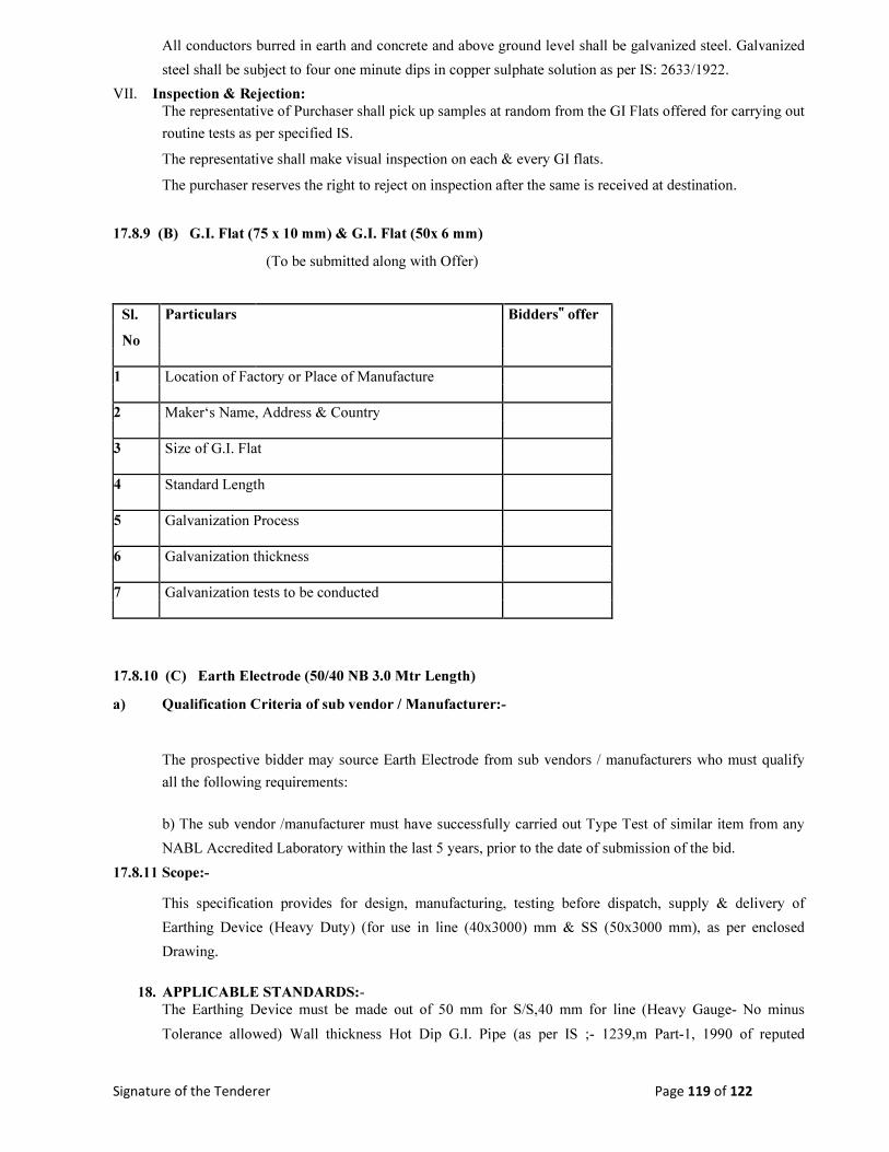
Signature of the Tenderer Page 119 of 122
All conductors burred in earth and concrete and above ground level shall be galvanized steel. Galvanized
steel shall be subject to four one minute dips in copper sulphate solution as per IS: 2633/1922.
VII. Inspection & Rejection:
The representative of Purchaser shall pick up samples at random from the GI Flats offered for carrying out
routine tests as per specified IS.
The representative shall make visual inspection on each & every GI flats.
The purchaser reserves the right to reject on inspection after the same is received at destination.
17.8.9 (B) G.I. Flat (75 x 10 mm) & G.I. Flat (50x 6 mm) (To be submitted along with Offer)
Sl. Particulars Bidders‟ offer
No
1 Location of Factory or Place of Manufacture
2 Maker‘s Name, Address & Country
3 Size of G.I. Flat
4 Standard Length
5 Galvanization Process
6 Galvanization thickness
7 Galvanization tests to be conducted
17.8.10 (C) Earth Electrode (50/40 NB 3.0 Mtr Length) a) Qualification Criteria of sub vendor / Manufacturer:-
The prospective bidder may source Earth Electrode from sub vendors / manufacturers who must qualify
all the following requirements:
b) The sub vendor /manufacturer must have successfully carried out Type Test of similar item from any
NABL Accredited Laboratory within the last 5 years, prior to the date of submission of the bid.
17.8.11 Scope:-
This specification provides for design, manufacturing, testing before dispatch, supply & delivery of
Earthing Device (Heavy Duty) (for use in line (40x3000) mm & SS (50x3000 mm), as per enclosed
Drawing.
18. APPLICABLE STANDARDS:-
The Earthing Device must be made out of 50 mm for S/S,40 mm for line (Heavy Gauge- No minus
Tolerance allowed) Wall thickness Hot Dip G.I. Pipe (as per IS ;- 1239,m Part-1, 1990 of reputed
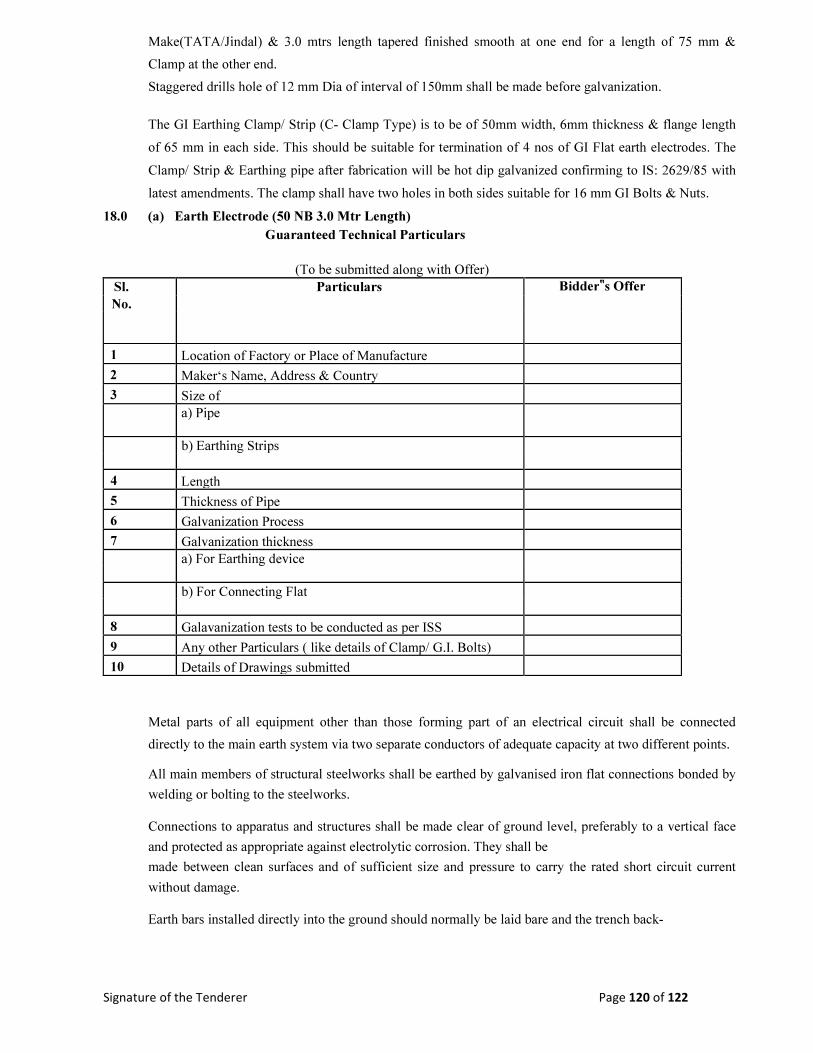
Signature of the Tenderer Page 120 of 122
Make(TATA/Jindal) & 3.0 mtrs length tapered finished smooth at one end for a length of 75 mm &
Clamp at the other end.
Staggered drills hole of 12 mm Dia of interval of 150mm shall be made before galvanization.
The GI Earthing Clamp/ Strip (C- Clamp Type) is to be of 50mm width, 6mm thickness & flange length
of 65 mm in each side. This should be suitable for termination of 4 nos of GI Flat earth electrodes. The
Clamp/ Strip & Earthing pipe after fabrication will be hot dip galvanized confirming to IS: 2629/85 with
latest amendments. The clamp shall have two holes in both sides suitable for 16 mm GI Bolts & Nuts.
18.0 (a) Earth Electrode (50 NB 3.0 Mtr Length)
Guaranteed Technical Particulars
(To be submitted along with Offer)
Sl. Particulars Bidder‟s Offer
No.
1 Location of Factory or Place of Manufacture
2 Maker‘s Name, Address & Country
3 Size of
a) Pipe
b) Earthing Strips
4 Length
5 Thickness of Pipe
6 Galvanization Process
7 Galvanization thickness
a) For Earthing device
b) For Connecting Flat
8 Galavanization tests to be conducted as per ISS
9 Any other Particulars ( like details of Clamp/ G.I. Bolts)
10 Details of Drawings submitted
Metal parts of all equipment other than those forming part of an electrical circuit shall be connected
directly to the main earth system via two separate conductors of adequate capacity at two different points.
All main members of structural steelworks shall be earthed by galvanised iron flat connections bonded by
welding or bolting to the steelworks.
Connections to apparatus and structures shall be made clear of ground level, preferably to a vertical face
and protected as appropriate against electrolytic corrosion. They shall be
made between clean surfaces and of sufficient size and pressure to carry the rated short circuit current
without damage.
Earth bars installed directly into the ground should normally be laid bare and the trench back-

Signature of the Tenderer Page 121 of 122
BREAKER FOUNDATION DESIGN
BREAKER ROD DETAILS

Signature of the Tenderer Page 122 of 122
ROD BINDING SCHEDULE REQUIREMENT OF RODS
72.41904 / 120 Wet Hard Soil Soil
Total TOTAL
SIZE VCB Mtr Kg./Mtr in Kg.
A. 10 tor 2*8*1.8 = 28.8 0.630 18.144
B. 10 tor 2*13*1.1 = 28.6
0.630
18.018
C. 12 tor 2*10*1.8 = 36
0.888
31.968
D. 6 tor 2*7*1.38 = 19.32 0.222 4.289
EXCAVATION: 2.15*1.4*1.2 = 3.612 Cum. 12.48
1
PCC:1:4:8 2.15*1.4*0.075 = 0.226 Cum. 0.462
RCC:1:2:4 1.2*1.915*0.2 = 0.4596 Cum.
2*(1.0*0.5*1.4) = 1.4 Cum.
1.8596 Cum. 2.421