Embed Size (px)
Citation preview

IMPORTANT: TENDERERS SHOULD READ THE TENDER PAPERS
CAREFULLY; SUBMISSION OF TENDER SHALL MEAN THAT THE TENDERER
HAS READ AND UNDERSTOOD ALL THE TERMS AND CONDITIONS OF THE
TENDER AND AGREES AND BINDS HIMSELF/THEMSELVES TO THE SAME.
ALL PAGES OF THE TENDER DOCUMENTS SHOULD BE SIGNED BY THE
TENDERER(S) AND RETURNED WITH THE TENDER.
PART – I
INVITATION OF TENDER
From: The General Manager.
Central Tool Room
A-5, Focal Point
Ludhiana-141 010
India.
To :
1.0 Sealed Tenders for following machinery/equipment/plant/softwares, as per
specifications given in the attached Schedule (Part-III), are invited by the General
Manager, Central Tool Room, Ludhiana, India (hereinafter called “the Tool
Room” and/or the “Purchaser”).
Sr.
No. Tender Description Tender No. & Date
1. Supplying, installation and commissioning
of 1000 KVA transformer
CTR/LDH/1810/Mach/15-18,
Dated: 16.01.2015
2. Supplying, installation and commissioning
of 11 KV VCB Panel
CTR/LDH/1810/Mach/15-21,
Dated: 19.01.2015
3. Supplying, installation and commissioning
of Knee type Universal Milling Machine
CTR/LDH/1810/Mach/15-142,
Dated: 20.11.2015
4. Supplying, installation & commissioning
of 100 KWp Capacity Solar Power Plant
CTR/LDH/1810/Mach/15-143,
Dated: 20.11.2015
5. Supplying, installation and commissioning
of 5-Axis CNC Milling Machine
CTR/LDH/1810/Mach/15-144,
Dated: 24.11.2015

6. Master Cam Software CTR/LDH/1810/Mach/15-145,
Dated: 03.12.2015
7. CNC Training Simulation Software CTR/LDH/1810/Mach/15-146,
Dated: 03.12.2015
8. NX Software CTR/LDH/1810/Mach/15-147,
Dated: 03.12.2015
The tenders shall be received up to 02.00 p.m. on 30.12.2015 and shall be
opened in the presence of intending tenderers at 2:30 p.m. on the same day i.e.
30.12.2015. Tenders received late will not be accepted. Tenders should be
accompanied by interest free Earnest Money as detailed below-
Sr.
No. Tender Description
Earnest Money
(in Rs.)
1. Supplying, installation and commissioning of 1000 KVA
transformer 20,000/-
2. Supplying, installation and commissioning of 11 KV
VCB Panel 10,000/-
3. Supplying, installation and commissioning of Knee type
Universal Milling Machine 20,000/-
4. Supply, installation & commissioning of 100 KWp
Capacity Solar Power Plant 2,50,000/-
5. Supplying, installation and commissioning of 5-Axis
CNC Milling Machine 3,00,000/-
6. Master Cam Software 15,000/-
7. CNC Training Simulation Software 10,000/-
8. NX Software 40,000/-
Earnest money is to be deposited in the form of Demand Draft in favour of
‘Central Tool Room Ludhiana’ payable at Ludhiana. The demand draft should be
enclosed in the envelop marked as Part ‘A’ described below at para 3.0 (a) and not
in the envelop marked as Part ‘B’. Tenders without Earnest Money or bank
guarantee in lieu thereof, will not be accepted. Tenderers registered with DGS&D
and/or NSIC for machine/equipment/goods mentioned in Part-III are exempted
from depositing Earnest Money and Security Deposit on submission of proof of
registration, along with the tender. The tenderers using the tender document
downloaded from our web site/CPPP portal are required to pay a non-refundable
tender fee of Rs. 500/- payable through Demand Draft in favour of ‘Central Tool
Room Ludhiana’ payable at Ludhiana. This DD should also be included in the
envelope containing Part ‘A’ of the tender.
2.0 Tenders must be submitted by registered post or deposited in the Tender Box kept
at Central Tool Room, A-5, Focal Point, Ludhiana-141 010, in a strong sealed
cover addressed to the General Manager, Central Tool Room, A-5, Focal Point,
Ludhiana, and distinctly marked as discussed at para 3.0 a), b) and c) below.

3.0 a) The tenders should be submitted in two parts. Part ‘A’ should contain the
technical specifications of the machine/equipments/goods, which should be
described in sufficient details. Detailed technical literature should be enclosed. It
should also be accompanied by a list of organizations where similar
machines/equipments/goods have been supplied by the tenders in India and out-
side India separately. No price should be indicated either for the
machines/equipments/goods with standard accessories or for special accessories in
this Part ‘A’. DD FOR EARNEST MONEY SHOULD ALSO BE ENCLOSED IN
THIS ENVELOP. All pages of this tender document are to be signed and returned
with this part ‘A’. All the documents as mentioned above should be placed in an
envelope which should be prominently marked as below:
PART ‘A’
Tender for : (Tender Description here)
Tender No. : (Tender No. here) Dated :(Tender date here)
Due on : 30.12.2015 At : 02:00 p.m.
This envelope should be securely fastened and sealed and addressed as
described in para 2.0 above and submitted as mentioned in paras 1.0 and 2.0
above.
b) Part ‘B’ of the tender should contain the prices quoted by the tenderer for the
machines/equipments/goods with standard accessories and special accessories
described in Part ‘A’ of the tender. It is very important that the prices are
quoted with reference to the description of the machine/equipment/goods and
other accessories offered in Part ‘A’ of the tender. Part ‘B’ of the tender should
be put in an another envelop which should be prominently marked as below:
PART ‘B
Tender for : (Tender Description here)
Tender No. : (Tender No. here) Dated : (Tender date here)
Due on : 30.12.2015 At : 02:00 p.m.
This envelope should be securely fastened and sealed and addressed as
described in para 2.0 above and submitted as mentioned in paras 1.0 and 2.0
above.
c) Both the envelopes marked Part ‘A’ and Part ‘B’ as mentioned in (a) and (b)
above should be put in another strong cover (Envelop) which should be
prominently marked as below:
Tender for : (Tender Description here)
Tender No. : (Tender No. here) Dated : (Tender date here)
Due on : 30.12.2015 At : 02:00 p.m.

This envelope should be securely fastened and sealed and addressed as described
in para 2.0 above and submitted as mentioned in Paras 1.0 and 2.0 above.
4.0 The strong cover mentioned in para 2.0 and 3.0 above shall be opened at 2.30 PM
on 30.12.2015 in presence of the intending tenderers. Part ‘A’ of the tenderers as
mentioned in Para 3.0 shall be opened in the presence of the tenderers immediately
thereafter (on 30.12.2015). Date and time of opening of Part ‘B’ of tender shall be
decided later on. At least five days’ notice to that effect shall be given to tenderers
whose tenders are under consideration after scrutiny of Part ‘A’ of tender, by any
of the means at the discretion of the Tool Room, and they may, at their discretion,
attend the opening of Part ‘B’ of tender.
5.0 The tenders should be valid for acceptance for a period of 90 days from the date of
tender opening (due date). It is understood that the tender documents have been
issued to the tenderers and the tenderers are being permitted to tender in
consideration of the stipulation on their part that after submitting their tenders they
will not resile from their offer(s) or modify the terms and conditions thereof.
6.0 If the equipment tendered deviates from tender specifications, a deviation
statement should be enclosed with Part ‘A’ of the tender. Even if there is no
deviation “Nil Deviation” confirmation should be enclosed with Part ‘A’ of the
tender.
7.0 a) If you are a firm (i.e. if you have a Partner or partner(s), the authorized partner
holding the Power of Attorney must sign each page of tender. A copy of the
partnership agreement should be enclosed. A copy of the Power of Attorney duly
executed in his favour authorizing him to bind the firm in all matters pertaining to
the contract, including the submission of any dispute relating to business of the
firm to arbitration, should be attached to the tender. Original documents are to be
shown, if desired.
b) If you are not a firm, the following certificate is to be attached to the tender:
“I certify that I am the sole proprietor and there is no other partner doing business
jointly with me.”
c) In case of the limited company, tender documents should be signed by the
managing director and the following certificate should be attached to the tender:
“I certify that I am the managing director and I hold the power of attorney
executed in accordance with the Articles of Association of the Company to sign all
the documents on behalf of the company.”
d) THE REQUISITE CERTIFICATE AS PER (a), (b) or (c) ABOVE, CURRENT
INCOME TAX CLEARANCE CERETIFICATE AND CERTIFICATE OF
REGISTRATION WITH DGS&D OR NSIC, IF APPLICABLE, ARE TO BE
ENCLOSED WITH PART “A” OF THE TENDER.

8.0 The Tool Room reserves the right to reject any or all offers without assigning any
reason whatsoever. The Tool Room also reserves the right to accept any tender in
whole or in part without assigning any reason whatsoever. The successful tenderer
shall be notified of the acceptance of the tender and till such intimation is received,
tenderer(s) should not make any arrangement or incur any expenditure in
anticipation of the receipt of notice of acceptance of the tender.
9.0 Machine/equipments/goods are to be installed and used at Central Tool Room,
Ludhiana, Punjab.
10.0 Other conditions of the Tender are:
i) The prices quoted in PART ‘B’ OF TENDER shall be on the following basis:
a) Foreign tenderers shall quote prices on the basis of FOB nearest port of
shipment, including seaworthy packing and handling & forwarding charges. In
the case of offers for imported machine/equipment/goods, tenderers shall
include in their offer the name of the person or the firm who will be acting as
their representatives/agent in India in respect of the offer. Tenderer shall also
indicate the service facilities which they or their representative/agent have in
India. If the foreign tenderer has no representatives in India they shall indicate
in their offer the service facility they intend to provide
CERTIFICATE IN SUPPORT OF RETENTION OF INDIAN AGENTS
INDICATING THE AGENCY COMMISSIONS INCLUDED IN THE PRICE
AND RESPONSIBILITIES OF THE SERVICE TO BE RENDERED BY THE
INDIAN AGENT, SHOULD BE ENCLOSED WITH THE TENDER.
b) In the case of indigenous offers, the tenderers are not entitled to any agency
commission. For indigenous machine/equipment/goods, the price quoted
should be FOR destination (Ludhiana) i.e. free delivery at site in the premises
of the Tool Room including unloading. Unless Excise Duty, Sales Tax, Octroi,
packing, handling and forwarding charges are indicated separately, these will
be presumed to have been included by the Tenderers in the price quoted.
c) In case tender is submitted by the Indian Agent for supply of
machine/equipment/goods from outside India, manufactured/supplied by their
Principals, Performa Invoice of their Principals should be enclosed with the
tender submitted by the Indian Agents which should clearly indicate price,
specifications, terms & conditions and the Indian agent’s commission and
responsibilities and services to be tendered by Indian agents.
ii) The basic consideration and the essence of the contract shall be strict adherence to
the stipulated time schedule for the supply of contracted machine/equipment/goods
i.e. “Time is the Essence of Contract”.

iii) a) In the case of foreign offers on FOB basis, insurance from the date of
shipment onwards shall be arranged by the purchaser. The contractor (the tenderer
whose tender has been accepted) shall give due notice in advance so that purchaser
can arrange insurance.
b) In the case of indigenous offers the purchaser will not pay separately for transit
insurance and the contractor will be responsible till the entire
machine/equipment/goods contracted, arrive in good condition at destination.
iv) In the case of FOB contract i.e. foreign supplies, the contractor should give
adequate notice to the forwarding agent to be notified by the purchaser about the
readiness of the cargo for shipment by an Indian vessel. The Bill of Lading should
be drawn as “FREIGHT TO PAY”.
v) Failure and Termination: On acceptance of tender, if the tenderer whose tender
is accepted fails to deliver the machine/equipment/goods within the period fixed
for such delivery in the contract or as extended or at any time repudiates the
contract before the expiry of such period the purchaser may without prejudice to
their other rights.
a) Recover from the Contractor Liquidated Damages and by way of penalty a
sum equivalent to 2% of the price of any machines/equipments/goods
(including element of taxes, duties, freights, etc) which the Contractor have
failed to deliver within the period fixed for delivery in the contract or as
extended, for each month or part of a month for which the delivery of such
machine/equipment/goods may be in arrears when deliver thereof is
accepted after expiry of the aforesaid period subject to maximum of 10.0%
of the contract value.
OR
b) Cancel the contract or a portion thereof and, if so desired and purchase the
machine/equipment/goods not so delivered or others of a similar description
(where machine/equipment/goods exactly complying with particulars are
not, in the opinion of the Purchaser [which shall be final] readily
procurable) at the risk and cost of the Contractor. It shall, however, be the
discretion of the Purchaser to obtain or not, the Performance Guarantee
Bond from the firm/firms on whom the contract is placed at the risk and
expense of the defaulting firm/firms.
vi) Force Majeure: The Contractor shall not be liable to forfeiture of security deposit,
liquidated damages or termination for default, if and to the extent the delay in
performance or other failures to perform its obligations under the contract is the
result of an event of Force Majeure. For the purpose of this clause “Force
Majeure” means an event beyond the control of the Contractor and not involving
the Contractor’s fault or negligence and not foreseeable. Such events may include,
but are not restricted to, acts of the Purchaser either in its sovereign or contractual
capacity, wars or revolutions, fires, floods, epidemics, quarantine restrictions and
freight embargoes. If a Force Majeure situation arises, the Contractor shall
promptly notify the Purchaser in writing of such condition and the cause thereof.
Unless otherwise directed by the Purchaser in writing, the Contractor shall
continue to perform its obligations under the contract as far as is reasonably
practical, and shall seek all reasonable alternative means for performance not
prevented by the Force Majeure event.
vii) Machine/equipment/goods are subject to inspection by the official/agency to be
authorised for this purpose by the Purchaser before shipment at Contractor’s work
and after receipt, installation and commissioning. The Purchaser may, at its
discretion, waive inspection before dispatch and inspect the same on receipt,
installation and commissioning at site, Tool Room’s right to inspect, test and,
where necessary, reject the machine/equipment/goods after the
machine/equipment/goods’ arrival and/or installation and commissioning shall in
no way be limited or waived by reason of machine/equipment/goods having been
previously inspected, tested and passed by the Tool Room or its authorised
representative prior to shipment or by waiver of inspection before shipment.
viii) Warranty Period: As per Schedule in Part III of Tender Documents, after
date of the Purchaser’s signed approval of the commissioning of the
machine/equipment/goods.
ix) Any dispute or difference arising in interpretations or applications of provisions of
the Contract shall be referred to the sole arbitration of Development
Commissioner, Ministry of MSME, Govt. of India or any other person appointed
by him. The award of the arbitrator shall be final and binding on both the parties.
Arbitration shall be governed by Indian Arbitration Act. In case of any litigation
the jurisdiction shall be Ludhiana
x) In case of any change in the constitution of firm tenderer/contractor shall notify the
same to the Tool Room provided that such change shall not relieve any former
member/partner of the firm from any liability under the contract and provided that
no new member/partner shall be accepted by the firm unless he agrees to abide by
all the terms and conditions of this contract.
xi) Delivery Required: As per Schedule in Part IV of Tender Documents.
xii) These tender documents are non-transferable.
For GENERAL MANAGER
Dated, Ludhiana, the 05th
December, 2015

PART – II(a)
TENDER
To
The General Manager,
Central Tool Room,
A-5, Focal Point,
Ludhiana-141010. (India)
Dear Sir,
I/We agree, on acceptance of the tender in whole or in part, to supply to Central
Tool Room, Ludhiana, India, the machine/equipment/goods and accessories, detailed in
the Tender enclosed herewith at prices quoted by me/us therein. I/We agree to hold the
offer open for 90 days from the due date. I/We have read and understood the terms and
conditions of the Tender Documents which shall become Contract on acceptance of
tender, and agree to be governed by the same. I/We specifically undertake that I/We will
not resile from my/our offer or modify the terms and conditions thereof.
Signature of the Tenderer
Place: Name : _______________
Date: Designation : ______________
Name & Address : ______________
of the firm _______________
WITNESS
Signature : _______________________
Name : _______________________
Designation : _______________________
Name & Address : ________________________
of the firm ________________________

Part-II (b)
Tender
Performa for commercial bid :-
(Tenderer need not use this document exclusively but the offer should be in this
format to the extent possible)
1. Tender No. & Date
2. Particulars of item/machine offered:-
Sr. No. Particulars Qty. Rate Amount
__________
Total __________
3. Particulars of Standard and Essential Accessories and Spares:-
Sr. No. Particulars Qty. Rate Amount
_________
Total _________
4. Particulars of optional Accessories & Spares:-
Sr. No. Particulars Qty. Rate Amount
_________
Total _________

5. Total Offer Price of Main items and Essential Accessories (2+3):
Amount Rate
i) Basic Amount :
ii) Packing charges :
iii) Excise duty :
iv) Sales Tax :
(We can issue form ‘C’ and are covered under VAT) :
v) Forwarding charges :
vi) Freight (pl. mention mode of Transport also) :
vii) Transit Insurance :
viii) Installation charges :
ix) Commissioning charges :
x) Training charges (Pl. specify free training and paid training :
for no. of personnel and days separately) :
xi) Any other charges (Pl. specify) :
(CTR will be at liberty to load the bidders with overheads etc. in
case these are not indicated explicitly)
__________
Total __________
xii) Delivery period
xiii) Warranty/Guarantee: -
(Pl. specify the details of parts not covered and mention whether the
warranty is for replacement or for repair. Responsibility for transportation
etc. for replacement/repair should also be clearly mentioned)
xiv) Inspection Details: -
xv) Payment terms: -
(Our payment terms are within 30 days from acceptance of material.
Deviations can be accepted in certain cases. But parties accepting our
payment terms shall be preferred)
PART – III
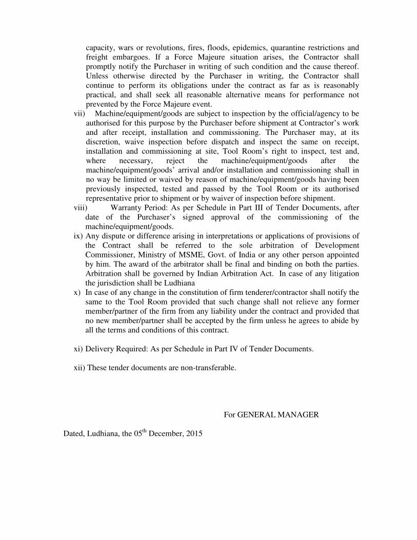
1. TECHNICAL SPECIFICATIONS FOR 1000 KVA TRANSFORMER
Required Qty. = 01 no.
Annexure – I
1. Type : Copper wound
2. Duty/Location : Indoor / Out door
3. Rating : 1000 KVA
4. No load Voltage ratio (KV) : 11/0.433 KV
5. Connections – HV / LV : Delta / Star
6. Vector Group : Dyn11
7. Toppings on HV for HV : +7.5 % to -7.5 %
Variation by an “Off in steps of 2.5 % each
Circuit” Tapping Switch
8. Permissible temperature rises
a) Top Oil : 50°C
b) Average Winding : 55°C
9. Cooling : ONAN
10. Altitude above Sea Level : Upto 1000 M
11. H.V. Termination : Cable Box
12. L.V. Termination : Cable Box
13. No Load Loss : 1.35 KW (IS TOL)
14. Full Load Loss : 13.5 KW (IS TOL)
15. % Z : 5 % (IS TOL)
16. Make : VOLTAMP/Siemens/Kirloskar
17. Colour of the transformer body: Steel Grey

Annexure: II
LIST OF FITTINGS & ACCESSORIES-
3-Phase, 50 Hz, Copper Wound, two Winding, Core type transformer, confirming to IS:
2026 - latest, with an active part mounted on top cover and having the following fittings &
accessories: -
Fittings:
01) 1 No. - Rating & Diagram Plate – Anodized Aluminum.
02) 2 Nos. - Earthing Terminals.
03) 4 Nos. - Lifting Lugs.
04) 1 No. - Oil Level Indicator with minimum level marking.
05) 2 Nos. - Thermometer Pockets.
06) 1 No. - Conservator with oil filling hole with cap and drain plug.
07) 1 No. - Air Release Plug.
08) 1 No. - Silica gel breather.
09) 1 No. - “Off Circuit” Tapping Switch.
10) 4 Nos. - Uni-directional Rollers.
11) - Jacking Pads.
12) - Radiators
13) - First Filling of Oil
14) - Epoxy Paint with Shade 631 of IS: 5.
15) 1 No. - Explosion Vent with Diaphragm
16) 1 No. - Bottom drain-cum-filter Valve.
17) 1 No. - Top Filter Valve.
Accessories:
01) 1 No. - Buchholz Relay with alarm & trip contact.
02) 1 No. - Oil Temperature Indicator.
Note:-
The tenderer shall be required to deposit 10% of P.O. value either in the form of
Bank Guarantee or Bank Draft, covering the warranty period.

2. TECHNICAL SPECIFICATIONS OF VCB PANEL FOR 1000 KVA
DISTRIBUTION TRANSFORMER
Required Qty. = 01 no.
11kv/630 Amp, 18.4 KA indoor type Vacuum Circuit Breaker complete, Single bus bar,
floor mounting metal clad indoor extensible type flush fronted horizontal draw out,
horizontal isolation type Vacuum Circuit Breaker suitable for installation in 11 kv, 3-
phase, 3-wire, 50 Hz, effectively earthed supply system having a fault level of 350 MV A
at 11 KV and equipped with:
• Housing for circuit breaker carriage and Mechanical interlock with automatic
safety shutter gear including padlocking arrangement. Epoxy support insulators
and self-aligning finger type isolating contacts. Truck having integral racking-in
device for insertion and withdrawable of VCB complete with all necessary
interlock and complete with sheet steel enclosure panel, bus bars, digital ammeter
and voltmeter indicators, selector switches, operating switches, heating element,
hooter etc. With dry type CT&PT units and IDMTL relay triple pole, non-
instantaneous, non-directional, having two elements for OIC Setting 50-200% and
one element for Elf protection setting 20-80%, CDG-31 (EQV) along with two
auxiliary relays and power pack unit for control circuit.
• ON/OFF, RYB, TNC, TCH indication lamps.
• HAND charged independent Spring closing / tripping, trip free operating
mechanism with manual closing and tripping push buttons and mechanical breaker
"closed / open”, "Spring Charged / discharged" indication.
• Mechanical operation counter.
• Electrical release coil and shunt trip coil of 24V DC.
• Make: ABB/CGL/Schnieder/Siemens.
• Colour of the main body: Steel Grey
NOTE:
1. All items shall be as per manufacturer’s standard practice.
2. The tenderer shall be required to deposit 10% of P.O. value either in the form of
Bank Guarantee or Bank Draft, covering the warranty period.
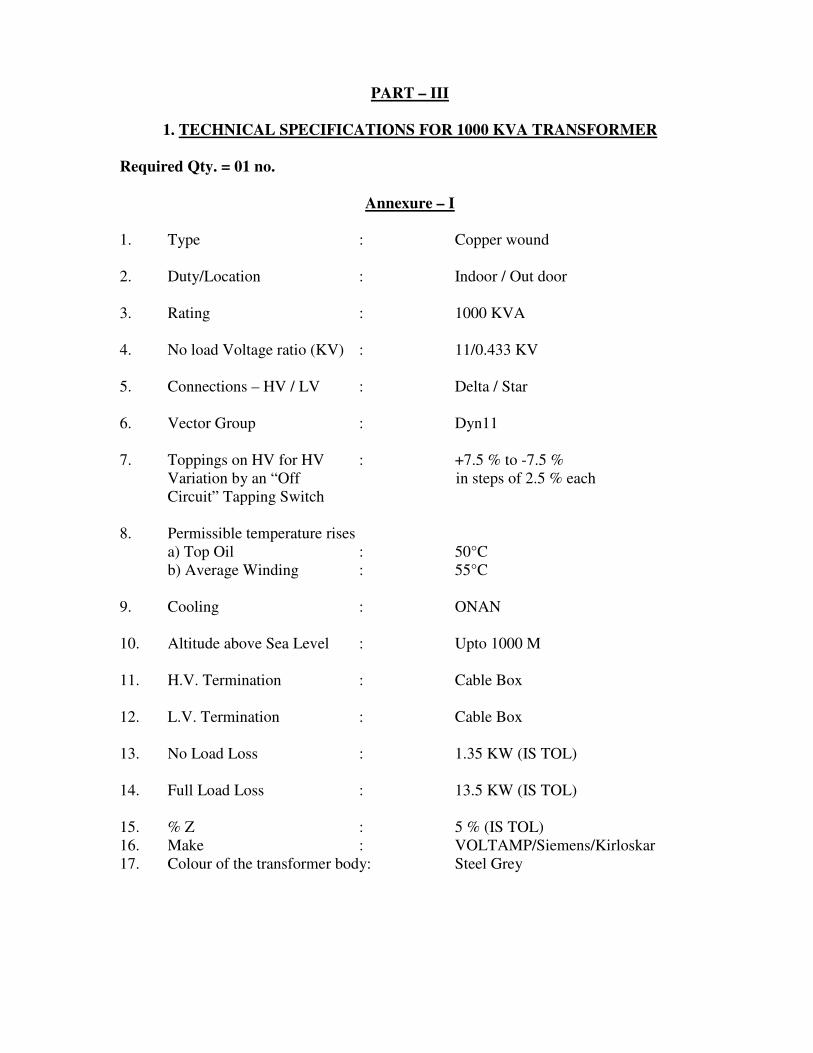
3. TECHNICAL SPECIFICATIONS FOR KNEE-TYPE UNIVERSAL MILLING
MACHINE
Required Qty. = 01 no.
Sr.No. SPECIFICATIONS Units
Offered
specifications (to be filled by the
tenderer)
A. Table-
1.
Overall dimensions-
Length, minimum
Width, minimum
1050 mm
230 mm
2.
Clamping area-
Length, minimum
Width, minimum
900 mm
230 mm
3.
T-slots-
No. off
Width
Centre distance
3 nos.
14 to 16 mm
45-65 mm
4.
Power operated traverse-
a) Longitudinal traverse, minimum
b) Transverse traverse, minimum
c) Vertical traverse (manual/auto), minimum
550 mm
250 mm
300 mm
5. Minimum distance from left hand table end to center of
milling spindle
160 mm
6. Swivel of table to either side ± 45°
7. Least count –axis measurement 0.020 mm
8. Safe weight on the table 150 Kg.
B. Milling Spindle-
1. Number of speeds 12
2. Speed range 45-2000 r.p.m.
3. Bore diameter of front bearing 65-70 mm
4. Spindle nose taper ISO 40
C. Feeds-
1. Number of feeds 18
2. Feed range-longitudinal/Transverse 16-800
mm/min.
3. Rapid rate-longitudinal/Transverse 4000 mm/min.

D. Power-
1. Main motor 2.2/1500
(KW/RPM)
2. Feed motor 0.75/1500
(KW/RPM)
3. Coolant motor 0.11/3000
(KW/RPM)
4. Lubrication
Centralized
Lubrication
System
5. Colour of the machine Apple Green
ACCESSORIES -
A. Standard Accessories-
1. Chip tray on base plate One
2. Service tools One set
3. Grease Gun One
4. Milling arbor ISO-40, ø27 x 500 mm One
5. Arbor support bearing brackets Two
6. Over-arm brace One
B. Special Accessories-
1. Stub arbor, ISO-40, ø16 x 17/25 mm One
2. Stub arbor, ISO-40, ø22 x 19/25 mm One
3. Stub arbor, ISO-40, ø27 x 21/25 mm One
4. Stub arbor, ISO-40, ø32 x 24/25 mm One
5. Stub arbor, ISO-40, ø40 x 27/63 mm One
6. Collet chuck, ISO- 40 One
7. Set of Collets, dia. 5-25 mm Set of 21 nos.
8. Machine lamp for 220-240 volts As required
9.
Reduction Milling Sockets, ISO-40/MT 1
ISO-40/MT 2
ISO-40/MT 3
ISO-40/MT 4
One no. each
10. Precision machine vice, opening: 150 mm One
11. Coolant equipment One
12. Anti-vibration elements One set

13. Universal Milling Head One
ACCURACY OF THE MACHINE-
1. Spindle run out, maxm. 0.010 mm
2. Squareness and straightness of the vertical movement of
the knee to the table surface (Knee not locked while
taking measurements)-
a) In the vertical plane of symmetry of the machine or
transverse vertical plane
b) In the plane perpendicular to vertical plane of
symmetry of the machine or transverse vertical plane
- 0.020 mm per 300
mm of measuring
length
- 0.020 mm per 300
mm of measuring
length
3. Parallelism of the table surface to its movement-
a) Transversely
b) Longitudinally
- 0.020 mm for any
length of 300 mm
- 0.020 mm for any
length of 300 mm
with a maxm.
permissible
deviation of 0.050
mm
4. Parallelism of arbor support guide on the over-arm to the
spindle axis-
a) In the vertical plane
b) In the horizontal plane
a) In the vertical plane
b) In the horizontal plane
- 0.020 mm for 300
mm (Over-arm
inclined downwards
only)
- 0.020 for 300
- 0.020 mm for 300
mm (Over-arm
inclined downwards
only)
- 0.020 mm for 300
mm
5. True running of the taper bore of the spindle:
a) Near to the spindle nose
b) At a distance L, when L=300 mm
- 0.010 mm
- 0.020 mm

NOTES-
1. 2 sets of Machine manuals (Operation and maintenance), spare parts catalogue,
machine test charts, calibration certificate in English language, shall be required
with the supply.
2. List of recommended spares to be offered, for two years of trouble free operation
of machine with cost of each item mentioned separately.
3. Deviations from specified specifications, if any, should be mentioned separately.
4. Warranty to be specifically mentioned.
5. PDI will be carried out at the supplier’s works by our representative(s) for
conformity to the machine specifications, accuracy and proving out of tooled up
components, on receipt of inspection call from the supplier. Supplier must inform
the PDI schedule atleast 10 days in advance. Supplier shall send detail pre-
inspection report including geometric accuracy report along with test charts, prior
to PDI call.
6. The machine shall be dispatched only after written “Acceptance / Inspection Note”
issued by the PDI team with clearly worded “Cleared for Dispatch” instruction.
7. Erection and commissioning is to be done by the supplier as per technical
specifications, terms and condition within the time period as per Supply order
(supplier to quote the time frame for Erection/Commissioning/Trial/Prove-out).
8. After erection and commissioning of the machine, the supplier shall prove the
geometrical accuracy and prove atleast three components in succession, at the
customer end.
9. The supplied machine should be complete in all respects in ready-to-operate
condition.
10. Supplier should be OEM (Original Equipment Manufacturer) or authorized
supplier.
11. The tenderer shall be required to deposit 10% of P.O. value either in the form of
Bank Guarantee or Bank Draft, covering the warranty period.
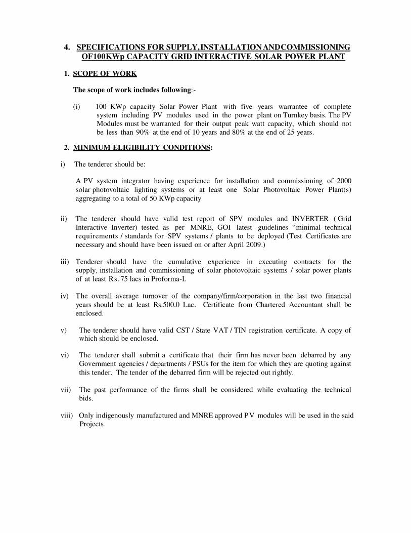
4. SPECIFICATIONS FOR SUPPLY, INSTALLATION AND COMMISSIONING
OF 100 KWp CAPACITY GRID INTERACTIVE SOLAR POWER PLANT 1. SCOPE OF WORK
The scope of work includes following:-
(i) 100 KWp capacity Solar Power Plant with five years warrantee of complete
system including PV modules used in the power plant on Turnkey basis. The PV
Modules must be warranted for their output peak watt capacity, which should not
be less than 90% at the end of 10 years and 80% at the end of 25 years. 2. MINIMUM ELIGIBILITY CONDITIONS:
i) The tenderer should be:
A PV system integrator having experience for installation and commissioning of 2000
solar photovoltaic lighting systems or at least one Solar Photovoltaic Power Plant(s)
aggregating to a total of 50 KWp capacity
ii) The tenderer should have valid test report of SPV modules and INVERTER ( Grid
Interactive Inverter) tested as per MNRE, GOI latest guidelines “minimal technical
requirements / standards for SPV systems / plants to be deployed (Test Certificates are
necessary and should have been issued on or after April 2009.)
iii) Tenderer should have the cumulative experience in executing contracts for the
supply, installation and commissioning of solar photovoltaic systems / solar power plants
of at least Rs.75 lacs in Proforma-I.
iv) The overall average turnover of the company/firm/corporation in the last two financial
years should be at least Rs.500.0 Lac. Certificate from Chartered Accountant shall be
enclosed.
v) The tenderer should have valid CST / State VAT / TIN registration certificate. A copy of
which should be enclosed. vi) The tenderer shall submit a certificate that their firm has never been debarred by any
Government agencies / departments / PSUs for the item for which they are quoting against
this tender. The tender of the debarred firm will be rejected out rightly.
vii) The past performance of the firms shall be considered while evaluating the technical
bids.
viii) Only indigenously manufactured and MNRE approved PV modules will be used in the said
Projects.
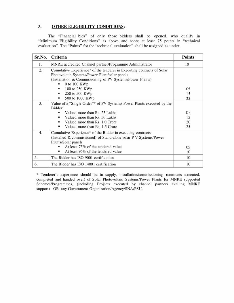
3. OTHER ELIGIBILITY CONDITIONS:
The “Financial bids” of only those bidders shall be opened, who qualify in
“Minimum Eligibility Conditions” as above and score at least 75 points in “technical
evaluation”. The “Points” for the “technical evaluation” shall be assigned as under:
Sr.No. Criteria Points
1. MNRE accredited Channel partner/Programme Administrator 10
2. Cumulative Experience* of the tenderer in Executing contracts of Solar
Photovoltaic Systems/Power Plant/solar panels
(Installation & Commissioning of PV Systems/Power Plants)
� 0 to 100 KWp
� 100 to 250 KWp
� 250 to 500 KWp
� 500 to 1000 KWp
05
15
25
3. Value of a “Single Order”* of PV Systems/ Power Plants executed by the
Bidder:
� Valued more than Rs. 25 Lakhs
� Valued more than Rs. 50 Lakhs
� Valued more than Rs. 1.0 Crore
� Valued more than Rs. 1.5 Crore
05 15 20
25
4. Cumulative Experience* of the Bidder in executing contracts
(Installed & commissioned) of Stand-alone solar P V Systems/Power
Plants/Solar panels
� At least 75% of the tendered value
� At least 95% of the tendered value
05
10
5. The Bidder has ISO 9001 certification 10
6. The Bidder has ISO 14001 certification 10
* Tenderer’s experience should be in supply, installation/commissioning (contracts executed,
completed and handed over) of Solar Photovoltaic Systems/Power Plants for MNRE supported
Schemes/Programmes, (including Projects executed by channel partners availing MNRE
support) OR any Government Organization/Agency/SNA/PSU.

Annexure-1
TECHNICAL SPECIFICATIONS OF 100 KWp GRID INTERACT IVE SPV POWER PLANT
ITEM DESCRIPTION
SPV Module � The photovoltaic modules should be Mono/Poly Crystalline with a total
array capacity of 100 KWp under STC
� The Photovoltaic modules must be qualified as per IEC 61215 (revised)/
IEC 61730 and in addition, the modules must conform to IEC 61730-1
requirements for construction & Part-2 requirements for testing, for safety
qualification.
� The PV modules must be tested and approved from any of the NABL /BIS/
MNRE Accredited Testing Calibration Laboratories.
� The s u p p l i e r s h a l l p r o v i d e performance guarantee for the PV modules
used in the power plant, must be warranted for their output peak watt capacity,
which should not be less than 90% at the end of 10 years and 80% at the end
of 25 years.
� The efficiency of the PV modules should be minimum 14%.
� Indigenously manufactured PV modules should be used.
Power
Conditioning Unit
with in-built
charge controller
Power conditioner unit with in-built charge controller of capacity 100 KWp should convert DC power into AC power, must confirm to standards IEC 61683
with 240 volt DC input and 440 (phase-to-phase) volt AC three phase output voltages will have following features:
� Wide input voltage range
� Output voltage 440 + 2% (phase-to-phase) of modified/pure sine wave.
� Out frequency: 50 Hz +0.5 Hz
� Capacity of PCU/Inverter is specified at 0.8 lagging power factor.
� Efficiency: > 90% at full load
� THD: less than 3%
� Protections:
- Over voltage (automatic shut-down)
- Under voltage (automatic shut-down)
- Overload
- Short circuit (circuit breaker & electronics protection against
sustained fault).
� Indications:
- Inverter ON
- Input & output voltage
- Input & output current
- Frequency
- Power output
� Display parameters
- Voltage of PV panels
- Output voltage
- Grid voltage
- Inverter loading
- Output frequency
� Cooling - Air cooled
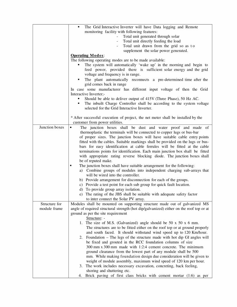
� The Grid Interactive Inverter will have Data logging and Remote
monitoring facility with following features:
- Total unit generated through solar
- Total unit directly feeding the load
- Total unit drawn from the grid so as t o
supplement the solar power generated.
Operating Modes :
The following operating modes are to be made available:
� The system will automatically ‘wake up’ in the morning and begin to
feed power, provided there is sufficient solar energy and the grid
voltage and frequency is in range.
� The plant automatically reconnects a pre-determined time after the
grid comes back in range
In case some manufacturer has different input voltage of then the Grid
Interactive Inverter;-
� Should be able to deliver output of 415V (Three Phase), 50 Hz AC.
� The inbuilt Charge Controller shall be according to the system voltage
selected for the Grid Interactive Inverter.
* After successful execution of project, the net meter shall be installed by the
customer from power utilities.
Junction boxes � The junction boxes shall be dust and water proof and made of
thermoplastic the terminals will be connected to copper lugs or bus-bar
of proper sizes. The junction boxes will have suitable cable entry points
fitted with the cables. Suitable markings shall be provided on the lugs or bus-
bars for easy identification at cable ferrules will be fitted at the cable
terminations points for identification. Each main junction box shall be fitted
with appropriate rating reverse blocking diode. The junction boxes shall
be of reputed make.
� The junction boxes shall have suitable arrangement for the following:
a) Combine groups of modules into independent charging sub-arrays that
will be wired into the controller.
b) Provide arrangement for disconnection for each of the groups.
c) Provide a test point for each sub group for quick fault location.
d) To provide group array isolation.
e) The rating of the JBS shall be suitable with adequate safety factor
to inter connect the Solar PV array. Structure for
module frame Modules shall be mounted on supporting structure made out of galvanized MS
angle of required structural strength (hot dip/galvanized) either on the roof top or at
ground as per the site requirement
Structure: -
1. The size of M.S. (Galvanized) angle should be 50 x 50 x 6 mm.
The structures are to be fitted either on the roof top or at ground properly
and south faced. It should withstand wind speed up to 120 Km/hour.
2. Foundation – The legs of the structure made with hot dip GI angles will
be fixed and grouted in the RCC foundation columns of size
300 mm x 300 mm made with 1:2:4 cement concrete. The minimum
ground clearance from the lowest part of any module shall be 500
mm. While making foundation design due consideration will be given to
weight of module assembly, maximum wind speed of 120 km per hour.
3. The work includes necessary excavation, concreting, back feeling,
shoring and shuttering etc.
4. Brick paving of first class bricks with cement mortar (1:6) as per

PWD specifications on edge type plate form is to be provided
under the modules structure area with minimum 1 meter more than
structure.
Connecting
cables � Module interconnections (4.0 mm
2 copper single core multi strand)
� Module parallel interconnection (10 mm2
copper single core multi
strand)
� Array or AJB to charge controller (125 mm2 copper two cores).
� PCU to load / change over (Single core copper cable 50.0 mm2
multi
strand) and for further distribution points (Single core copper cable 4.0 mm
2 and 2.5 mm
2 multi strand)
- All cables to be supplied should be as per BIS and should have proper current
carrying capacity and should not be heated.
- All cables shall be adequately supported.
- Outside of terminal/panels/enclosures shall be protected by conduits.
Cables shall be provided with dry type compression glands wherever they
enter junction boxes, panels, enclosures.
Load connection The supplier shall also ensure that main points of the building should be
connected keeping in view the capacity of the plant.
Indoor wiring All indoor wiring is to be done in a casing capping system. As and when
required flexible pipe may also be used.
Lighting protection Suitable nos. of lighting arrestors shall be provided in the array field.
Earthling
protection Each array structure and all metal casings of the plant etc. shall be earthed
properly.
Tool Kit and
Spares One necessary tools kit and spares will have to be provided by the supplier
CODES AND STANDARDS FOR SAID SOLAR POWER PLANT:
The BoS items / components of the SPV power plant must conform to the latest edition of
IEC/ equivalent BIS Standards as specified below:
BoS item / component Standard Description Standard Number
Power Conditioning Unit
Inverter Efficiency Measurements
Environmental Testing
IEC61683 and must additionally conform to the relevant national/international Electrical Safety Standards IEC60068 2 (6, 21, 27, 30, 75, 78)
Charge controller/ MPPT
units* Design Qualification
Environmental Testing IEC 62093 IEC 60068 2 (6,21,27,30,75,78)
Cables General Test and Measuring Methods PVC insulated cables for
working voltages upto and
including 1100 V-Do-, UV
resistant for outdoor
installation
IEC 60189 IS 694 / IS 1554
IS/IEC 69947

Switches / Circuit Breakers
/ Connectors General Requirements
Connectors-safety IS/ IEC 60947 part I, II & III
EN 50521 Junction Boxes/ Enclosures General Requirements IP 65 ( for outdoor) / IP/21
(for indoor) IEC 62208
SPV System design PV Stand-alone Systems design verification
IEC 62124
Installation Practices Electrical Installations of
buildings-requirements for
SPV power supply systems
IEC 60364-7-712
*Must additionally conform to the relevant national/ International Electrical Safety Standards.
NOTE:
1. Attach a duly signed list of such spare parts as are absolutely necessary for proper
maintenance and operation of 100 KW Capacity Grid Interactive Solar Power
Plant for a period of two years, with price for each spare part.
2. The tenderer shall be required to deposit 10% of P.O. value either in the
form of Bank Guarantee or Bank Draft, covering the warranty period.

5. TECHNICAL SPECIFICATIONS FOR 5-AXIS CNC MILLING MACHINE
Quantity Required = 01 no.
Sr. No Item Specifications Offered
Specification REMARK
5-Axis CNC Milling Machine
Traverse Linear Axes-
� Min. 700 mm in X-Axis.
� Min. 500 mm in Y-Axis.
� Min. 500 mm in Z-Axis.
No. of axis to be controlled by CNC = 5
Head tilting or Table tilting travel +1100 / -35
0
C-axis table rotation = 00 To 360
0.
CNC Control = X, Y, Z movement, Table rotation & head
tilting/table tilting; Simultaneous interpolation axes = 5
1. Field of Application
1.1. The Machine will be used for the following
applications.
1.1.1. Machining of single jobs and batch production.
1.1.2. Standard machining of press tool plate, die plates,
mould plates, fixtures, Precision machining jobs in :
- Face, shoulder, pocket milling.
- Drilling & Boring application
- Tapping.
1.1.3. Five axis simultaneous machining of :
- Forming & stamping tool components
- Die casting Die components
- Injection moulding components
- Other free form machining components
- Machining of tyre moulds, Turbine blades and
Aerospace Parts
- Measuring of parts and setting fixture
with Measuring probe head with
Measuring cycle (optional)
1.2. The following Tool Holding & Cutting Tools must
be able to use.
Tool holding:
1.2.1.1. Suitable for Tool Shank BT-40/SK-40 (Drawing
sketch and tool shank drawing to be attached in
the quotation).
1.2.1.2. Spindle tool adapting suitable for automatic tool
change as per BT-40/SK-40.
1.2.1.3. Solid and modular tool holders with or without
internal coolant supply for automatic tool
change.
2. Technical data 2.1. Work area dimensions : (approximately)
Linear Traverses-
� Min. 700 mm in X-Axis
� Min. 500 mm in Y-Axis
� Min. 500 mm in Z-Axis

No. of axes to be controlled by CNC = 5
Head tilting or Table tilting travel +1100 / -35
0
C-axis table rotation = 00 To 360
0.
CNC Control = X, Y, Z movement, Table rotation. & head
tilting/table tilting; Simultaneous interpolation axes = 5
2.2 PLATTER
2.2.1 Platter Length/width min. 600 x 500 mm
2.2.2 Spindle nose to table : 600 mm
2.2.3 Table weight carrying capacity: 300 kgs.
2.3. Machine Spindle & Head Stock
2.3.1. Spindle speed : Min. 8,000 rpm
Opt. 12,000 rpm
2.3.2. Balanced Spindle
2.3.3. Drive System : Gear Drive
2.3.4. Power = 30 HP / 22.4 KW approx.
2.3.5. Torque = min.120 Nm
2.3.6. Oil cooled and permanent spindle lubrication display
function at CNC Control Monitor
Internal coolant supply frequency-controlled
Air cooling through the spindle
Synchronized with bed temp preferred.
2.3.7. Digital controlled AC Spindle Motor drive
2.3.8. Spindle with hydraulic / pneumatic operated
automatic tool changing and through spindle air
blow for cleaning while tool change.
2.3.9. Tool adapting support SK40 / BT40
2.3.10. Power failure detection module. 2.4. Coolant system
2.4.1 Tank with Waste oil separator
2.4.2 Tank capacity= min. 250 lit. or more
2.4.3 Air for Dry Machining through the spindle
Adjustable external coolant nozzles or
Programmable Coolant Nozzle.
2.5. Axis drives & control
2.5.1. Digital controlled drive and motors for all axes.
2.5.2. In-line direct drive
2.5.3. Closed pitch ball screws, supported at both ends,
pre-tensioned
2.5.4. Rapids X/Y/Z Axis : Min 20 m/min
2.5.5. Rapid A/B Axis : Min 2000 deg/Min
2.5.6. Acceleration : 7 m/s2
2.6. CNC Control Unit features
2.6.0 Heidenhain/Siemens/Fanuc/Haas or latest control
RAM=512 MB or more for control
Application Hard disk=30GB or more and
provision for increasing the memory.
2.6.1. RISC/CISC/Triple 32-bit processor.
2.6.2. 5-axes simultaneous controllable
2.6.3. Faster data processing rate and block processing
suitable for high speed milling application.(1000
blocks/sec)
2.6.4. HSM Look Ahead Function, Min. 80 blocks

2.6.5. Programming syntax as per DIN 66025, ISO and
additional manufacturer own syntax.
Least increment 0.001mm with decimal input.
Spindle functions S, incl. Spindle Operation.
Feed functions f, G-code & M-code
Tool functions T, Tool length and cutter dia.
compensation G-code, 3-D cutter compensation,
Tool Load Monitoring.
Interpolations
Standard A] positioning
B] Linear interpolation
C] Helical
Optional A] Involute
B] Polar coordinate
C] Cylindrical
RS232 DNC interface
I/O interface Ethernet with ISO/EIA auto-
discrimination.
Rigid tapping function
Measuring cycles for touch probe(Optional)
Standard cycles as per ISO std.
USB Port for communication
Part program storage Min 40 GB on Hard disk
Display of PLC alarm and message
Over travel control
Emergency stop on control panel, remote control &
tool loading device
CNC controller to take care of,
Stored pitch error compensation
Backlash compensation for cutting traverse
Backlash compensation for rapid traverse
Friction compensation control
Electronic Thermal Compensation
Feed forward control
Standard cycle (canned)
2.6.6. 15” TFT Colour Monitor or more with soft keys.
2.6.7. Swiveling Panel with in-build keyboard, monitor &
operating knobs.
2.6.8. Feed control potentiometer 10%. Increments from 0 –
150%.
2.6.9. Spindle speed control potentiometer 10% Increments
from 0 – 150%.
2.6.10. Emergency brake knob
2.6.11. Machine hour reading
2.6.12. Spindle load display (KW)
2.6.13. AC control for PLC and drive control cabinet, self-
diagnostic function (optional)
2.6.14. Input resolution & display.
2.6.15. Linear axis 0.001mm or better
2.6.16. Angular axis=0.0010 or better

2.7. ACCURACY
2.7.1 Positioning : ± 0.007 mm
2.7.2 Repeatability : ± 0.005 mm
2.7.3 Run out : 0.003 mm run-out at Spindle Nose
3. Accessories
3.0 Control Panel A/C. in-built required
3.1. Chip conveyor.
3.2. Fully enclosed splash guard with slide windows.
3.3. Fully encapsulated housing with safety type
window.
3.4. Automatic Tool Magazine for min. 30 tools and
Changer with safety guard. Max tool weight Min 5
Kg. Preferably CAM Type. Max. tool dia. 100 mm
random access. Max. Tool Length 300 mm
3.5. Leveling pads
3.6. Door safety interlock
3.7. Remote Jig Handle
3.8. Touch probe (make Renishaw) (Optional)
3.9. Work-piece washing gun
3.10. PLC controlled central lubrication system
3.11. Run hour meter
4. Spare parts- Spare and wear parts for two years. A detailed
recommendation list must be provided with price list along
with the quotation.
� Part a. Mechanical
� Part b. Electronic
� Part c. Electrical
5. Documentation- Each documentation three sets in English
(along with machine delivery)
5.1. Detailed layout plan and prospect to be given
5.2. Operating and Programming instruction
5.3. Installation and Commissioning instructions
5.4. Quality Test records
5.5. Maintenance / repair charts
5.6. Preventive maintenance instructions
5.7. Lubrication chart & parameter list
5.8. Requirement/recommendation for power supply
controlled stabilizing has to be given
5.9. Instruction manual for supplied coolant Concentrate and
coolant maint.
5.10.Detaled invoice and packing list of all items and devices
and detailed prospect of machine and all other
accessories enclosed in respective boxes.
6. Installation & commissioning-
The complete installation and commissioning must be carried
out by the supplier at the project (at the final destination/
premises). Certificate of acceptance is to be signed by
customer and supplier.
7. Training must be provided at final destination place-
7.1. Operator training 10 days
7.2. Programming course 5 days

7.3. Maintenance course mechanical, electrical and electronic
3 days.
8. Service-
The authorized Service Partner in India (Name & Address)
must be certified by manufacturer and shown in the quotation
9. Warranty: Min. 2 years.
10. Manufacturer should have established ‘after sales & service’
network in India.
No of similar machine installed in India- minimum 5 Nos.
NOTE:
1. Machine to be supplied in Steel Grey colour.
2. The tenderer shall be required to deposit 10% of P.O. value either in the form of
Bank Guarantee or Bank Draft, covering the warranty period.

6. SPECIFICATIONS OF MASTER CAM SOFTWARE
Master Cam (Perpetual License), Latest Version (Educational Licenses)
Required Quantity = 02 Bundles (10 Licenses each in one bundle)
Note:-
1. Six days training shall be required at the time of installation of the software on
free-of-cost basis.
2. One year up-gradation to be provided free-of-cost.
3. Authorization letter/proprietary certificate from CNC Software Inc. shall be
required to be submitted along with the offer, failing which offer shall be
summarily rejected.
4. Post processors for CTR machine controls like Fanuc, Siemens, HAAS,
Heidenhain etc. to be provided, including post processors for 5- axis milling.

7. SPECIFICATIONS OF CNC TRAINING SIMULATION SOFTWARE
CNC Training Simulation Software (Stand-alone licenses)
Quantity: 10 Licenses
• Should be PC based simulation software which could be operated on any windows
platform.
• Should be able to design and simulate the actual performance of a CNC system.
• Should be able to exhibit 3D realistic effect of 2-axis CNC Turning Centre and 3-axis
CNC Vertical Machining Centre.
• Should be able to exhibit realistic 3D machining process simulation with chips, coolant
and sound effect.
• On-screen operator panel which should be just similar to machine panel.
• Should be available in all prevailing latest versions of industrial controls in the market like
Fanuc, Siemens, Heidenhain, Fagor, Mazak, Haas etc.
• Work piece selection and clamping and setting simulation should be possible.
• Should contain extensive tool library and options to select variety of tools for both turning
and machining centre, with option to customize tool as per the user need.
• Measurement and surface roughness measurement simulation possibility.
• Should support all canned cycles and macros for CNC Turning and CNC Machining
centre.
• Should be able to import programs generated by post processors of 3D modelling
softwares.
• Should be able to support dual graphics-Tool path graphics and 3D graphics.
• Should be equipped with a program editor wherein programs could be created, edited and
saved.
• Program Compiler to identify the syntax error in the program.
• Help file to provide syntax and sample G codes / M codes programs.
• Should be equipped with Program Converter to convert other G codes/M codes
programs.
• MDI panel to run commands instantly.
• 3D simulation viewer with features like Zoom, Pan, View, Rotate, Program Datum
settings, Billet settings, Tool settings, collision detection.
• Should be equipped with advanced post processors compatible with various industrial
control systems.
• Software manuals to be provided as hard copy.
• The simulation of the system should occur in an offline environment.
• Six days training to be imparted at the time of software installation in CTR.
• One year Up-gradation to be provided free-of-cost.
• Authorization letter/proprietary certificate from Principal shall be required to be submitted
along with the offer, falling which offer shall be summarily rejected.

8. SPECIFICATIONS OF NX SOFTWARE
1. Technical Details NX CAD/CAE/CAM Academic Bundle (Quantity 10 Nos.)
(NXACAD100+101) NX Academic Perpetual License
Bundle includes:-
• NX CAST ONLINE LIB ‐ SINGLE
• NX Design Simulation
• NX SCHEMATICS
• NX Gateway
• NX DRAFTING
• NX Prod & Manufacturing Information PMI
• NX PROGRESSIVE DIE WIZARD
• NX SOLID MODELING
• NX FEATURE MODELING
• NX FREEFORM MODELING NX WELD ASSISTANT
• NX DIE ENGINEERING
• NX RENDER
• NX FREEFORM SHAPE
• NX VISUALIZE SHAPE
• NX ANALYZE SHAPE
• NX KNOWLEDGE FUSION AUTHOR
• NX KNOWLEDGE FUSION SHARING
• NX MOLD WIZARD
• NX ASSEMBLIES
• NX ADVANCED ASSEMBLIES
• NX USER‐DEFINED FEATURES
• NX WAVE CONTROL
• Body Design Concurrent License
• General Packaging Concurrent License
• NX Motion Simulation NX3 & NX4
• NX STRENGTH WIZARD
• NX TURNING
• NX POST EXEC
• NX POST BUILDER
• NX LIBRARY GENIUS ACCESS
• NX CAM VISUALIZE
• NX FACET MACHINING
• NX VARIABLE AXIS MILLING
• NX GRAPH TOOL PATH EDITOR
• NX CORE AND CAVITY MILLING
• NX FLOW CUT
• NX SEQUENTIAL MILLING

• NX NURBS PATH GENERATOR
• NX WIRE EDM
• NX SHOP DOC
• NX FEATURE BASED AUTOMATION
• NX SHEET METAL DESIGN
• NX ADVANCED SHEET METAL DES
• NX FABRIC FLATTENER
• Advanced Simulation
• NX OPEN C AUTHOR
• NX OPEN GRIP RUNTIME
• NX OPEN GRIP AUTHOR
• NX OPEN RUNTIME PACKAGE
• NX OPEN TOOLKIT PKG DEVELOP
• NX OPEN C++ AUTHOR
• NX Open User Interface Styler
• NX IGES TRANSLATOR
• NX DXF/DWG TRANSLATOR
• NX STEP TRANSLATOR
• NX STEP TRANSLATOR
• NX 2D EXCHANGE
• Siemens PLM Software Internal NX ELECTRO‐MECHANICAL ROUTING
• NX WEB EXPRESS
• Contour Profiling
• NX RAPID PROTOTYPING
• NX CAM BASE
• NX PLANAR MILLING
• NX Open Toolkits Author
• NX Human Modeling
• NX Human Modeling Posture Prediction
• XpresReview
NX Academic Perpetual License V2
Bundle Includes:-
• NX CAST ONLINE LIB ‐ SINGLE
• NX Thermal Simulation
• NX Flow Simulation
• NX Ansys Environment
• NX ABAQUS Environment
• NX Nastran Desktop Advanced
• NX Nastran Rotor Dynamics Desktop
• NX Nastran Desktop: Optimization
• NX Nastran Desktop Adv. Non-linear Solver
• The Optimization Wizard

• NX Advanced Simulation
• XpresReview
• NX Design Simulation
• NX Advanced Thermal Simulation
• NX Space Systems Thermal Simulation
• NX Electronic Systems Cooling Simulation
• NX Response Simulation
• NX Laminate Composites
• XpresReview
• NX Design Simulation
• NX Advanced Thermal Simulation
• NX Space Systems Thermal Simulation
• NX Electronic Systems Cooling Simulation
• NX Response Simulation
• NX Laminate Composites
• NX Simulation Process Builder
• The Optimization Wizard
• NX Advanced FEM
• NX CATIA V5 Interface
• Tolerance Stackup Validation
• NX Electrode Design
• NX Mach 4 Ship Design
• NX Motion Simulation‐RecurDyn
• NX Motion Simulation‐RecurDyn
• Siemens PLM Software Internal NX Motion Control Simulation
• NX Motion Control Simulation
2. AMC of NX Academic Bundle, NX ACAD 100+101 for one year
Notes: 1. AMC charges to be quoted separately.
2. One year up-gradation to be provided free-of-cost.
3. Authorization letter/proprietory certificate from Siemens India shall be required to be submitted
along with the offer, failing which offer shall be summarily rejected.
4. Six days training shall be required at the time of installation of the software on free-of-cost.
5. Post processors for CTR machine controls like Fanuc, Siemens, HAAS, Heidenhain etc. to be
provided, including post processors for 5-axis milling.
6. The tenderer shall be required to deposit 10% of P.O. value either in the form of Bank Guarantee
or Bank Draft, covering the warranty period.
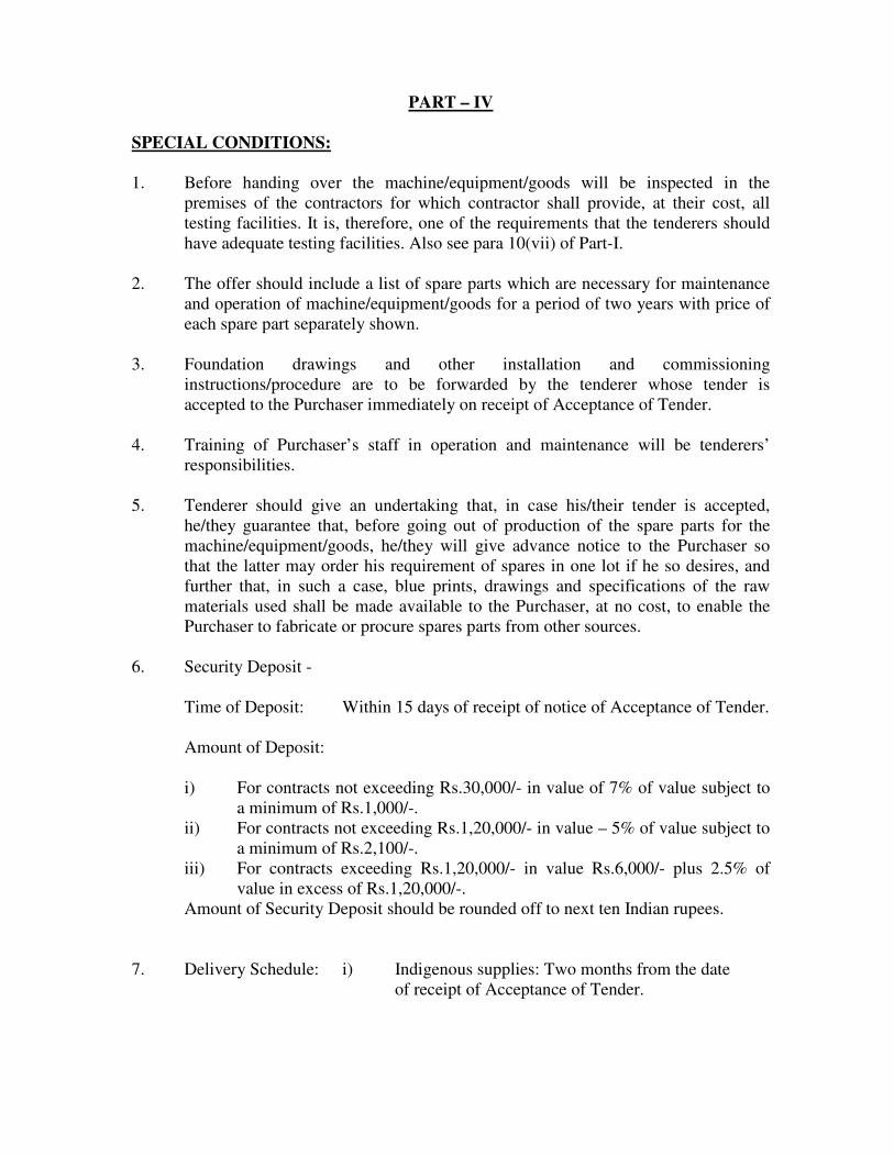
PART – IV
SPECIAL CONDITIONS:
1. Before handing over the machine/equipment/goods will be inspected in the
premises of the contractors for which contractor shall provide, at their cost, all
testing facilities. It is, therefore, one of the requirements that the tenderers should
have adequate testing facilities. Also see para 10(vii) of Part-I.
2. The offer should include a list of spare parts which are necessary for maintenance
and operation of machine/equipment/goods for a period of two years with price of
each spare part separately shown.
3. Foundation drawings and other installation and commissioning
instructions/procedure are to be forwarded by the tenderer whose tender is
accepted to the Purchaser immediately on receipt of Acceptance of Tender.
4. Training of Purchaser’s staff in operation and maintenance will be tenderers’
responsibilities.
5. Tenderer should give an undertaking that, in case his/their tender is accepted,
he/they guarantee that, before going out of production of the spare parts for the
machine/equipment/goods, he/they will give advance notice to the Purchaser so
that the latter may order his requirement of spares in one lot if he so desires, and
further that, in such a case, blue prints, drawings and specifications of the raw
materials used shall be made available to the Purchaser, at no cost, to enable the
Purchaser to fabricate or procure spares parts from other sources.
6. Security Deposit -
Time of Deposit: Within 15 days of receipt of notice of Acceptance of Tender.
Amount of Deposit:
i) For contracts not exceeding Rs.30,000/- in value of 7% of value subject to
a minimum of Rs.1,000/-.
ii) For contracts not exceeding Rs.1,20,000/- in value – 5% of value subject to
a minimum of Rs.2,100/-.
iii) For contracts exceeding Rs.1,20,000/- in value Rs.6,000/- plus 2.5% of
value in excess of Rs.1,20,000/-.
Amount of Security Deposit should be rounded off to next ten Indian rupees.
7. Delivery Schedule: i) Indigenous supplies: Two months from the date
of receipt of Acceptance of Tender.
ii) Imported supplies: Within two months from the date
of issue of Acceptance of Tender or one month from
opening of Letter of Credit whichever happens later.
8. The tender is required to give on a separate sheet ‘Total life Cycle costing’ of the
machine.
9. Position of availability of Service Engineer in case of break down along with
expected time to reach CTR and position of availability of spare parts in future
should clearly be stated.
Signature of the Tenderer
Place: Name :
Date: ______ Designation :
Name & Address of the firm : _____________________
________________________
________________________
WITNESS Signature :
Name :
Designation :
Name & Address of the firm :