Embed Size (px)
Citation preview

1
J V G C - W I S U T E C
Prepared for:
DHMP-PIUOffice No. 2152/1 Toktonalieva StreetBishkek 720055Kyrgyz Republic
p.a. GEOCONSULT ZT GmbHCONSULTING ENGINEERSHOELZLSTRASSE 5635071 WALS - SALZBURG, AUSTRIATEL. +43 - 662 - 65 9 65 - 0FAX +43 - 662 - 65 9 65 - 10E-mail [email protected] www.geoconsult.at.
Kyrgyz Republic:Disaster Hazard Mitigation Project (DHMP)
Relocation of TP 3 and TP 18 material to TP 6
Tender DocumentsVolume II
Section 7 Technical SpecificationsSection 8 DrawingsSection 9 Bill of Quantities
Salzburg/Chemnitz 2008
Disaster Hazard Mitigation Project (DHMP)Tender Documents, Volume 2.Relocation of TP03 and TP18 material toTP6

2
J V G C - W I S U T E C
Kyrgyz Republic:Disaster Hazard Mitigation Project (DHMP)
Relocation of TP 3 and TP 18 material to TP 6
Working Design
Tender DocumentsVolume II
Section 7 Technical SpecificationsSection 8 DrawingsSection 9 Bill of Quantities
JV Geoconsult/WISUTECProject Management JV Geoconsult/WISUTECDeputy Project Management C. Kunze JV Geoconsult/WISUTECChief Design Engineer R. Schulz JV Geoconsult/WISUTECTailing Specialist M. Paul
Salzburg/Chemnitz 2008
Disaster Hazard Mitigation Project (DHMP)Tender Documents, Volume 2.Relocation of TP03 and TP18 material toTP6

3
C O N T E N T S
Section 7. Technical Specifications……. …………………………4Section 8. Drawings………………………………………………..64Section 9. Bill of Quantities………….……………………………66
Disaster Hazard Mitigation Project (DHMP)Tender Documents, Volume 2.Relocation of TP03 and TP18 material toTP6

4
Section 7
TECHNICAL SPECIFICATIONS
Part I. SPECIAL PROVISIONSPart II. TECHNICAL PROVISIONS
Disaster Hazard Mitigation Project (DHMP)Tender Documents, Volume 2.Relocation of TP03 and TP18 material toTP6
5
Part I. SPECIAL PROVISIONS
Disaster Hazard Mitigation Project (DHMP)Tender Documents, Volume 2.Relocation of TP03 and TP18 material toTP6

6
Part I. Special provisions
CONTENTSSP 1 General..........................................................................................................8SP 2 Description of works......................................................................................9SP 3 Engineering back-up...................................................................................21SP 4 Scope of works............................................................................................21SP 5 Construction schedule.................................................................................21SP 6 Definitions...................................................................................................21SP 7 Use of soils for construction........................................................................22SP 8 Right of passage for access and transportation procedures.......................22SP 9 Operation and maintenance of access roads..............................................22SP 10 Transport route during relocation/ Construction of roads crossings...........22SP 11 Access for implementation of topographic surveys.....................................23SP 12 Works within the right for access................................................................23SP 13 Restoration of soils used for passage.........................................................23SP 14 Communications, electric power transmission lines and telecommunications
....................................................................................................................24SP 15 Safety plan..................................................................................................24SP 16 Clearing of operation area...........................................................................24SP 17 Utilization of waste......................................................................................24SP 18 Preservation of landscape...........................................................................24SP 19 Prevention of water pollution.......................................................................25SP 20 Temporary settlements of the Contractor....................................................25SP 21 Survey data.................................................................................................25SP 22 Construction surveys...................................................................................25SP 23 Ensuring personnel and equipment for investigations................................26SP 24 Reference specifications and standards for materials................................26SP 25 Responsibilities of the Contractor...............................................................27SP 26 Mobilization and preparations.....................................................................27SP 27 Mobilization payments.................................................................................27SP 28 Substantive provisions on rating and payment...........................................27SP 29 Rating for payment......................................................................................27SP 30 Payments....................................................................................................28SP 31 Contract drawings.......................................................................................28SP 32 Construction drawings.................................................................................28SP 33 Definition of the terms “Drawings”...............................................................28CONSTRUCTION ACTIVITIES...............................................................................................32Section 1. Plan of location and of construction equipment of the contractor..............33Section 2. The Engagement of civil works..................................................................33Section 3. Breakdown and control topographic works................................................33Section 4. Materials provided by the Contractor.........................................................36Section 5. Materials and quality..................................................................................36Section 6. Recommended specifications and standards............................................37Section 7. Access roads to working sites and routes of transportation......................37Section 8. Use of soils for construction purposes.......................................................38Section 9. Operation and maintenance of access roads.............................................39Section 10. Existing protection fences..........................................................................39Section 11. Electric power transmission lines...............................................................39Section 12. Ensuring traffic of public transport..............................................................40Section 13. Protection of immovable property locating along access roads to working
sites.............................................................................................................40Section 14. Construction on existing water-currents and communications....................41Section 15. Right to change the site and plan................................................................42Section 16. Geological investigations............................................................................42Disaster Hazard Mitigation Project (DHMP)Tender Documents, Volume 2.Relocation of TP03 and TP18 material toTP6

7
Section 17. Safety plan..................................................................................................42Section 18. Preservation of vegetation..........................................................................43Section 19. Protected plants and animals......................................................................44Section 20. Prevention of water pollution.......................................................................44Section 21. Preservation of historical and archeological monuments............................45Section 22. Clearing and waste disposal.......................................................................46Section 23. Water Drainage and protection of water-currents during construction........47Section 24. Technical Specifications for “Reno” mattresses..........................................48Section 25. Technical Specifications for reconstruction of existing Roads....................49Section 26. Reconstruction of existing Bridge................................................................49Section 27. Technological roads....................................................................................49Section 28. Water treatment facility...............................................................................50Section 29. Truck wash plants.......................................................................................50Section 30. Drainage Systems for surface dewatering..................................................51Section 31. Rain storage reservoir.................................................................................52Section 32. QA/QC Program..........................................................................................52Section 33. SRC cover...................................................................................................53EARTH WORKS 54Section 1. Specifications for earth and stone works....................................................55CONCRETE - TECHNICAL CONDITIONS AND SPECIFICATIONS.....................................63Section 1. Concrete......................................................................................................64Section 2. Main requirements to concrete....................................................................64Section 3 Cement........................................................................................................65Section 4 Sand............................................................................................................67Section 5 Coarse aggregate.......................................................................................69Section 6 Water...........................................................................................................71Section 7 Concrete quality control measures and concrete quality test program.......72Section 8 Deviations of Facilities and surface tolerances for concrete structures......73Section 9 Preparation for concrete laying...................................................................76Section 10 Concrete laying..........................................................................................78Section 11 Dosage.......................................................................................................81Section 12 Mixing.........................................................................................................83Section 13 Temperature of concrete............................................................................85Section 14 Concrete curing measures.........................................................................86FORMWORK – TECHNICAL SPECIFICATIONS...................................................................87Section 1 Formwork, General.....................................................................................88Section 2 Formwork casing and Facing......................................................................88Section 3 Uniformity of formwork material..................................................................90Section 4 Finishing and finishing works......................................................................91Section 5 Molded surfaces..........................................................................................91Section 6 Unmolded surfaces.....................................................................................92REINFORCMENT BARS - TECHNICAL SPECIFICATIONS..................................................93Section 1 Reinforcement bars, general.......................................................................94Section 2 Materials......................................................................................................94Section 3 The placing of reinforcement bars...............................................................94ROLLED SECTIONS AND STRUCTURAL SHAPES, ROLLED PRODUCTS FOR BRIDGE
CONSTRUCTION – TECHNICAL SPECIFICATIONS................................96Section 1 General.......................................................................................................97Section 2 Materials......................................................................................................97List of Drawings 100
Disaster Hazard Mitigation Project (DHMP)Tender Documents, Volume 2.Relocation of TP03 and TP18 material toTP6

8
SP 1 General
The former Uranium deposits of the Mailuu-Suu river valley are geographically located in western spurs of the Ferghana ridge, at the south-western slopes of Baubashata ridge (northern bank of Ferghana hollow). Administratively the region is included to Jalalabat oblast of the Kyrgyz Republic. The main settlement is Mailuu-Suu town, which is linked with the cities Bishkek, Jalalabat, and Osh by asphalted highways.
The territory is characterized by a very varied morphology, deeply incised valleys. It ranges in altitude from 850-1200 m ASL.
The hydrological system of the region comprises Mailuu-Suu river with several tributaries. The river sources are mixed of snow-spring type. Minimum water levels are observed in July and August. In spring longer lasting floods are caused by the snow melt in the mountains. Heavy rainfalls can trigger short-term flash floods. Surface water stream of Mailuu-Suu river are divided by weirs for irrigation purpose at outlet of the valley.
The prevailing climate is continental. Average annual temperature is +10 °С 12°С, depending on altitude. Maximum temperatures reach +34°С, and minimum -30°С (for height 1700 m). Summers are generally hot and dry, winters temperate cold with frequent snowstorms. Average annual precipitation is up to 680 mm/year according to the meteorological stations of Mailuu-Suu and Andizhan, evaporization - 312 mm/year. The majority of precipitations falls to in the winter and spring seasons. Dominating winds have northern-eastern directions, rarely - southern ones. Seismic risk of territory is estimated to reach magnitude 9.
One of the major peculiar factors about Mailuu-Suu mine waste dumps and tailings (impoundments) is their location in narrow valleys or steep slopes, often exposed to geotechnical instabilities. This exposure to active exogenous geological processes (landslides) is exacerbated by the regionally high seismic risk. The location of some tailings and waste dumps in the vicinity of rivers, streamlets, and even within settlements, often combined with the hazards of avalanches, mudflows and landslide risks complicate the design and construction of protection structures.
Purpose of the Project
A risk assessment of Mailuu-Suu area resulted in the evaluation of two high risk tailings ponds. The main purpose of the Project is to mitigate the structural failure risk of TP 03 and TP 18 near the Mailuu-Suu river. Both tailings ponds sites are highly endangered by possible seismic events and landslides. The relocation of these two tailings ponds to the safer disposal site TP 06 provides long term safety.
The tailings of TP3 and TP18 will be mixed stepwise with existing inert material (coverage, alluvium and subsoil) and afterwards relocated to TP6 by using a special truck. But before relocating the material there will be a construction road, a truck wash plant and a water treatment system built. The existing roads as well as the existing bridge between TP3/18 and TP6 will be improved.
In advance the disposal site have to be prepared (dam construction which is a separate project, construction road and wash plant for trucks within this project). The compacted
Disaster Hazard Mitigation Project (DHMP)Tender Documents, Volume 2.Relocation of TP03 and TP18 material toTP6
9
tailings mixture and the dam will be covered with a protective cover layer (type SRC – Source and Release Cover) after emplacement at TP6.
SP 2 Description of works
Situation before beginning projectThe preparatory works comprise the dam construction using waste dump material from WD 5 (about 50,000 m³). For the maintenance of the drainage system about 50 m concrete duct (D=1000 mm) is built through the dam. At the beginning of the project the complete dam is situated at TP 6 area.
Succession of the civil works for the engineering structures There are 3 main working parts for relocation of the TP 3 and TP 18 waste. The single successions are listed.
2.1 Pick up of tailings and sedimentary material from TP 3The design of the remedial measures and of different construction stages is presented with the attached drawing no. TP3-01…TP3-24. In the report in hand the years of construction measures are called ‘year 1’ and ‘year 2’. According the actual state of knowledge it implies year 2008 and 2009.
2.1.1 The first construction period June-October/November year 1:
In total ca. 50,000 m³ to max. 60,000 m³ of mixed materials shall be relocated from TP 3 during the construction period in year 1. The construction works comprise the following major work steps:
2.1.1.1 Preparatory works
a) Mobilization of equipment and installations at the site
b) Installation of a water treatment plant next to southern corner of the dam toe of TP3
c) Construction of a new construction road on top of the existing construction road for access to TP 3. The construction road begins at the road Mailuu-Suu – Kara Agach and ends on the dam crest of the tailings dam.
d) Construction and operation of a carwash station for trucks next to the entrance of the construction road to the existing street Mailuu-Suu – Kara Agach
e) Construction of a new trench (made of concrete elements) for diverting surface runoff from the hinterland along the southern side of TP3 and connection of this trench to the existing concrete trench at the southern side of the tailings dam. The size of this trench shall be at least of 1 m depth and of 1 m width (minimum cross section area 1 m²). Along the southern side of TP 3 the concrete trench shall be founded on concrete foundations in the geologic underground layer
a) Geotechnical and hydrogeological investigation program including installation of temporary groundwater monitoring wells in the tailings and on the dam slope area.
Disaster Hazard Mitigation Project (DHMP)Tender Documents, Volume 2.Relocation of TP03 and TP18 material toTP6

10
2.1.1.2 Works accompanying the relocation works
a) Repeated removal and reconstruction and continuous maintenance of the trench (made of concrete elements) for diverting runoff from the hinterland stepwise following to the ongoing excavation works. Surface runoff from the hinterland is to be diverted directly to the Mailuu Suu River via the concrete trench located on the dam slope of TP3
b) Installation of a sump for collection of surface water contaminated by tailings materials and repeated removal and reconstruction of this sump during ongoing excavation works. All surface water collected on TP3 below the concrete trench for diverting runoff from the hinterland is assumed to be contaminated and therefore is to be diverted to the water treatment plant before being discharged to the Mailuu Suu river. For this a pump and a removable pipeline is to be installed to divert the surface water to the water treatment plant. The sump is to be removed repeatedly as needed during ongoing excavation works.
c) During all excavation works a minimum 2 m high protection dam shall stay in place
along the entire actual dam crest. Due to lowering the excavation level in the pond area the sediment material located in the dam shall be dozed onto the air-exposed tailings surface creating a trafficable working platform for the following excavation step. A minimum height of the remaining dam crest above the surface of the placed sediment layer on the tailings of at least 2 m must be granted at all the time of the project.
d) Implementation of a QA/QC-program during the entire project. The project progress
has to be controlled based on geotechnical and hydrogeological investigations carried out and evaluated in advance of specific works. The start of every work step mentioned above is to be allowed for by the on-site monitor of the Employer. During ongoing excavation works QA/QC-measures are to be carried out continuously applying the observation method.
e) In advance of excavation of tailings layers temporary groundwater monitoring wells (or piezocones alternatively) have to be installed to measure a potential groundwater table in the tailings. Measurement results have to be evaluated.
f) Resulting from the evaluation carried out under (1.2.5) measures have to be taken to lower a potential groundwater table in permeable tailings layers and optionally in the underlying quaternary sediment layer. The following optional water diversion measures shall be foreseen:
Installation of drainage trenches on the actual surface to grant surface runoff in direction of the water collection sump. The pump in the water collection sump must be dimensioned to grant a dry surface of the tailings during the ongoing excavation works. Collected water is to be pumped to the water treatment plant
Lowering the groundwater table in the tailings by installation of wells and
pumping. Pumped water is to be diverted to the water treatment plant for treatment before being discharged.
Disaster Hazard Mitigation Project (DHMP)Tender Documents, Volume 2.Relocation of TP03 and TP18 material toTP6

11
g) Continuous steering, monitoring and maintenance of the water treatment plant and of the water management of surface waters on TP 3.
2.1.1.3 Relocation works
Construction phase 1
Construction phase 1 includes the following major works:
a) Excavation of the internal protection dam located on the pond surface and transport to the new depository on TP 6 (estimated volume ca. 850 m³)
b) Excavation of ca. 5,000 m³ of sediments from the area shown on drawing TP3-12 and transport to the new depository on TP 6.
c) Dozing of ca. 3,000 m³ of the remaining sediment volume overlying the concrete cover layer in the area shown on drawing TP3-12 from the southern to the northern part of the area shown on drawing TP3-12.
d) From the free-lying concrete cover surface in-situ shear vane testing shall be carried out in according to the requirements of the QA/QC-program. The spatial distribution of the shear strength is to be evaluated in a narrow grid. Based on the results of the measurements of in-situ shear strength the area is to be divided up in construction strips. Construction strips of low shear strength have to be identified. Based on the results of the evaluation of the spatial undrained shear strength distribution a decision is to be taken whether standard technology for excavation and transport can be applied for the respective strip.
e) Alternative technology for excavation and transport: It is expected that most of the tailings can be excavated and transported using standard technology as presented below. For a minor amount of the tailings volume it cannot be excluded that an alternative technology is needed. The alternative excavation technology uses an excavator with a long arm backhoe or a cable excavator that excavates these tailings of pulpy consistency in a distance of at least 15 m from the location of the excavator. This excavator must stand on a sufficiently trafficable embankment layer. Therefore the concrete layer must not be crushed before the decision has been taken whether the standard technology presented below is applicable. Excavated pulpy tailings should be transported by trucks with watertight lockable containers to the new depository. These tailings shall be spread in specific areas in 0.5 m thick layers and mixed layer-wise by placement of a 1 m thick soil layer consisting of sand-gravel mixture.
f) Crushing of the free-lying concrete cover layer (thickness ca. 30 cm) to pieces (size: below 30 cm x 30 cm x 30 cm) where the overlying sediments have been removed before.
Disaster Hazard Mitigation Project (DHMP)Tender Documents, Volume 2.Relocation of TP03 and TP18 material toTP6
12
g) Excavation of the crushed concrete debris including the underlying 1.5… 2 m thick layer consisting of sediments and tailings. The requirements of the QA/QC-program have to be met.
h) Repeated dozing of 3000 m³ of sediments from the northern to the southern part of the area shown on drawing TP3-12 and placement of ca. 1.0…1.3 m thick layer of sediments. After that a layer thickness of at least 2 m thickness including the underlying tailings shall be excavated. Light-weight dozers shall be used (max. soil pressure 27 kPa)
i) Dozing of the remaining ca. 3,000 m³ of sediments in the area shown on drawing TP3-12 from the northern part onto the tailings in the southern part.
j) Repeating of the works steps from (1.3.6) to (1.3.8) in the northern partial area shown on drawing TP3-12. A minimum thickness of 1.3 m of sediments must remain in the southern part of the area shown on drawing TP3-12. Light-weight dozers must be used (max. soil pressure 27 kPa)
Construction phase 2
Construction phase 2 includes the following major works steps:
k) Continuation of the layerwise excavation shown on drawing TP3-12 including excavation of ca. 2 m thick layers consisting of an upper at least 1 m thick sediment layer together with the underlying uppermost ca. 0.75 m to 1 m thick tailings layer. After that a new sediment layer of at least 1 m thickness shall be placed on air-exposed tailings by dozers. The sediment layer placed by dozers acts as a trafficable surface for hydraulic excavators and for the trucks. Sediments for constructing the trafficable working platform layer shall be relocated from the Eastern area of TP3 by dozing the sediments downhill and further ahead on the free-lying tailings surface. Relocated sediments shall then be placed on the air-exposed (tailings) surface by leight-weight dozers (max. soil pressure of the tracks: 27 kPa). Further technical details are presented in the QA/QC-program. The requirements of the QA/QC-program have to be fulfilled.
l) In order to grant sufficient trafficability for the earthwork machines and trucks and workers safety the needed thickness of the placed sediment layer and the excavation depths allowed have to be controlled in advance for each layer based on in-situ shearvane testing as described in the QA/QC-program. For this in situ shearvane tests have to be carried out from each placed sediment layer proving sufficient trafficability before the next excavation step can start. Further details are presented with the QA/QC-program.
m) Crushing of the free-lying concrete cover layer (thickness ca. 30 cm) to pieces (size: below 30 cm x 30 cm x 30 cm) where the overlying sediments have been removed before (see drawing TP3-20 and following ).
n) Excavation of the crushed concrete debris including the underlying 1.5…2 m thick layer consisting of sediments and tailings and follow up of work steps (1.3.9) to (1.3.10) on the areas shown on the drawings TP3-13.
Disaster Hazard Mitigation Project (DHMP)Tender Documents, Volume 2.Relocation of TP03 and TP18 material toTP6
13
o) Contaminated soils in the underground of tailings must be relocated as well. It is assumed that at least a layer thickness of 1 m is to be removed. For this a hydraulic excavator removes the uppermost 1 m thick soil layer on the air-exposed slopes above the actual excavation level. Such soil shall be used for construction of sediment layers on free-lying tailings surfaces as well. For this such soil shall be dozed downhill and further ahead on free-lying tailings surfaces together with the uppermost sediment layer.
p) In the central parts of the former valley quaternary sediments form a several m thick layer consisting of silty sand-gravel mixtures. After removal of the uppermost 1 m thick layer of potentially contaminated soils the underlying soil layer shall be used as to the extent needed as construction material to place 1 m thick sediment layers on air-exposed tailings surfaces during ongoing excavation works.
q) At the end of the construction period year 1 a temporary at least 1.0 m thick temporary cover consisting of sediments shall be placed on the remaining actual pond surface. For this the entire sediment layer above the concrete layer located in the upper part of southeastern valley shall be dozed downhill into the remaining part of the pond. All areas affected by construction works during the construction period year 1 shall be temporarily covered for the winter period. Only if needed additional clean soil should be supplied from outside TP 3 onto the pond surface. The free-lying concrete cover located in the southeastern valley shall stay in place during the winter period year 1/year 2.
r) The trench for diverting runoff from the hinterland has to be reconstructed in the respective area at the end of construction period of year 1. Surplus sediment material from the upper southeastern valley area shall be stored nearby in the central part of the pond.
Construction phase 3 and following construction phases:
The following works listed under (A) to (B) shall be carried out before the end of construction period year 1 if possible. Otherwise these works would be the first works of construction period year 2.
(1) The concrete cover and the underlying sediments and tailings in the southwestern valley shall be excavated. For this at first the free-lying concrete cover layer (thickness ca. 30 cm) is to be crushed to pieces (size: below 30 cm x 30 cm x 30 cm) where the overlying sediments have been removed before winter period year 1/year 2.
(2) Excavation of the crushed concrete debris including the underlying 1.5… 2 m thick layer consisting of sediments and tailings in the southeastern valley.
(3) Placement of a 1 m thick sediment layer by dozing the surplus sediments from the central part of TP 3 into the southwestern valley. In the central part of the pond an at least 1 m thick layer of sediments must be left behind. Work step (A) and (B) shall be repeated until all tailings above the actual level of the tailings surface will have been excavated.
Disaster Hazard Mitigation Project (DHMP)Tender Documents, Volume 2.Relocation of TP03 and TP18 material toTP6

14
2.1.2 Winter period year 1/year 2
(1) At the end of the construction period of year 1 the protection dam along the dam shoulder must be cut and an overflow outlet for diverting heavy precipitation events shall be installed at the inflow of the concrete trench along the southern side of the dam. The pond surface shall be covered with a 1 m thick layer of clean soils. The cover surface must be shaped granting a stable surface runoff from TP 3 pond surface to the overflow outlet. The overflow outlet shall be made of concrete (width 1.0 m; height min. 1.0 m). This outlet avoids any unacceptable ponding of surface runoff behind the actual dam crest.
(2) A slope toe buttress shall be built up in front of the toe of the temporary slopes along the northern valley and the central valley. For this surplus sediment relocated from the south western valley can be used. The front slope of the toe buttress shall be inclined v:h = 1 : 4. The buttress shoulder line shall be at the level 1022 m. If needed sediment incorporated in the temporary slopes along the northern and the central valley can be dozed downhill to build up the slope buttress layer. In this case the slopes of the sediment layer along the northern and the central valley can be flattened as much as possible. This slope flattening is limited by the position of the existing trench for diverting surface runoff.
(3) Continuous maintenance of the functionality of all water management installations
(4) Regular inspections at the site (acc. to the QA/QC-program)
2.1.3 The second construction period April/May to October/November year 2
The construction works comprise the following major work steps:
(I) Preparatory works
(1) Continuation of the works presented under (2.1.1.1), if needed.
(II) Works accompanying the relocation works
(1) Continuation of the works presented under (2.1.1.2) with respect to the requirements presented with (1.2) and with the QA/QC-program.
(III) Relocation works above excavation level 1000 m
The following construction phases include the following major work steps. During all work steps the requirements presented with the QA/QC-program have to be fulfilled.
(1) Continuation of the layerwise excavation works in the central part of the pond starting with excavation of the temporary cover placed before the winter period year 1/year 2. In the beginning the temporary cover layer will be excavated together with ca. 1 m thick layer of the underlying tailings.
Disaster Hazard Mitigation Project (DHMP)Tender Documents, Volume 2.Relocation of TP03 and TP18 material toTP6

15
(2) Layerwise removal of the sediment layer from the northeastern pond area by dozing the sediments downhill into the central part of the pond and placement of 1 m thick sediment layers on freelying tailings surfaces.
(3) Excavation of an upper at least 1 m thick placed sediment layer together with the underlying uppermost ca. 1 m thick tailings layer. The cycle of work steps (2) and (3) shall be continued until all sediments from above the concrete layer located in the northeastern pond area will have been removed into the central pond area.
(4) In order to grant sufficient trafficability for the earthwork machines and trucks and workers safety the needed thickness of the placed sediment layer and the excavation depths allowed have to be controlled in advance for each layer based on in-situ shearvane testing. For this in situ shearvane tests have to be carried out from each placed sediment layer proving sufficient trafficability before the next excavation step can start. For further details see QA/QC-program. (5) Crushing of the free-lying concrete layer to pieces in the northeastern area of the pond (see. 1) (2 northeastern valleys and pond area located east of cross section no. 3).
(6) Excavation of the concrete debris and the underlying sediments and tailings in the northeastern pond area (east of cross section no. 3) in one working step. In this area only a thin layer of sandy tailings is to be excavated. Here no sediments need to be placed to create a trafficable working platform.
(7) Contaminated soils in the underground of tailings must be relocated as well. It is expected that at least a layer thickness of 1 m is to be removed. For this a hydraulic excavator removes the uppermost 1 m thick layer from the air-exposed slopes above the actual excavation level.
(8) In the central parts of the former valley quaternary sediments underneath the tailings form a several m thick layer consisting of silty sand-gravel mixtures. After removal of the uppermost 1 m thick layer of potentially contaminated soils the underlying soil layer shall be used as construction material to place 1 m thick sediment layers on air-exposed tailings surfaces during ongoing excavation works. For this such soil shall be dozed from the two northeastern valleys into the central pond area.
(9) Continuation of the excavation works in the central pond area as described above until all quaternary subsoil (silty sand-gravel mixture) will have been utilized.
(10) After all sediment materials and quaternary subsoil material will have been utilized only sediments from the dam body area are available to build trafficable working platforms. If necessary an additional amount of clean soil (sand-gravel mixture with a sizing equal to the sediment layer overlying the concrete layer) must be supplied to the site and used to build up trafficable working platforms for contiunuation of the excavation works.
(IV) Relocation of the last part of TP3 below excavation level 1000 m.
(1) A temporary construction road shall be built on the existing dam slope by excavation into the dam slope. The construction road shall be constructed according to the same
Disaster Hazard Mitigation Project (DHMP)Tender Documents, Volume 2.Relocation of TP03 and TP18 material toTP6

16
design as the first construction road built before. The carwash station is to removed to a location next to the dam toe of TP3.
(2) The old construction road material shall be removed onto TP 3 and utilized to build up a trafficable layer during ongoing excavation works.
(3) Excavation of the remaining tailings as described under (III). For construction of trafficable layers the following materials shall be used: quaternary subsoil from the valley; dam material; clean soil from outside TP3 only if needed. The entrance of the construction road on the dam crest shall be removed stepwise due to lowering of the dam crest level until all tailings and contaminated soils will have been removed from the subsurface of TP 3.
(4) A final radiological monitoring program shall be carried out to prove that all contaminated soils have been removed. If needed remaining contaminated soils are to be excavated and transported to the new depository on TP 6.
(5) Final smoothening of the subsurface to grant a stable surface runoff.
(6) Installation of an outlet trench connected to the existing concrete outlet located at the southern corner of the existing TP 3.
(V) Demobilisation works
(A) At the end of the remedial works the Contractor shall remove all installations and equipment from the site. Any damages on the existing road in front of the dam toe have to be repaired.
2.2 Pick up of tailings and sedimentary material from TP 18
The total volume of tailings included in TP 18 is estimated to be about 3,000 m³. The total volume of contaminated subsoil underneath the tailings is estimated to be 1,000 m³. The tailings and contaminated soils shall be relocated to the new depository on TP 6.
The following major work steps have to be carried out.
(1) In order to get access to the excavation site a ramp of earthen materials shall be constructed if needed. This ramp is to be relocated to the new depository at the end of the relocation works on TP 18. (2) The tailings and contaminated shall be excavated using hydraulic excavators and loaded on trucks for transportation to the new depository to TP 6. After tailings excavation the subsoil of TP 18 shall be clean from any remaining contaminated soil. For this at least the uppermost 0.5 m thick layer of the subsoil shall be excavated everywhere underneath tailings. The occurrence and distribution of contamination in the remaining subsoil shall be investigated according to the radiological monitoring program. Any contaminated soils found shall be excavated as well and transported to the new depository site on TP 6.
Disaster Hazard Mitigation Project (DHMP)Tender Documents, Volume 2.Relocation of TP03 and TP18 material toTP6

17
2.3 Regime of excavation and transport from TP 3 and TP 18 to the new depository on TP 6
(1) Traffic regime
The trucks shall drive on in a ring cycle on two roads.
Transport of excavation materials from TP 3 and TP 18 will be performed along the existing road on the left side of Mailuu Suu river in one way traffic regime. The total length of this transportation route from TP3 and TP18 to the new depository on TP6 is approx. 3 km. There is a bridge at the northern end of Mailuu-Suu city and a second bridge 300 m south of TP 6 area. The second bridge will have been reconstructed before the beginning of the works under this project.
The public road along the right river side from northern city to the village Kara-Agash shall be used as well. A further transport from Kara-Agach to TP 6 is possible via a construction road (currently under construction). This construction road will be used for relocation of WD 5 waste dump material and relocation of TP3 and TP 18 tailings and waste dump material respectively. Empty trucks from TP6 shall drive following the road on the right side of the Mailuu-Suu river also in one way traffic regime via the existing concrete bridge located at the northern outskirts of Mailuu Suu town and back to TP3 and TP18 (approx. 5 km).
Only one construction road for transport of materials from TP 3 and for access of trucks on TP 3 is needed, because of the small numbers of transport cycles per hour. This road will be used in both directions. Therefore traffic direction on this road has to be controlled by supervising personnel or by a traffic light system.
(2) Limiting requirements for suitable earthwork equipment and truck types:
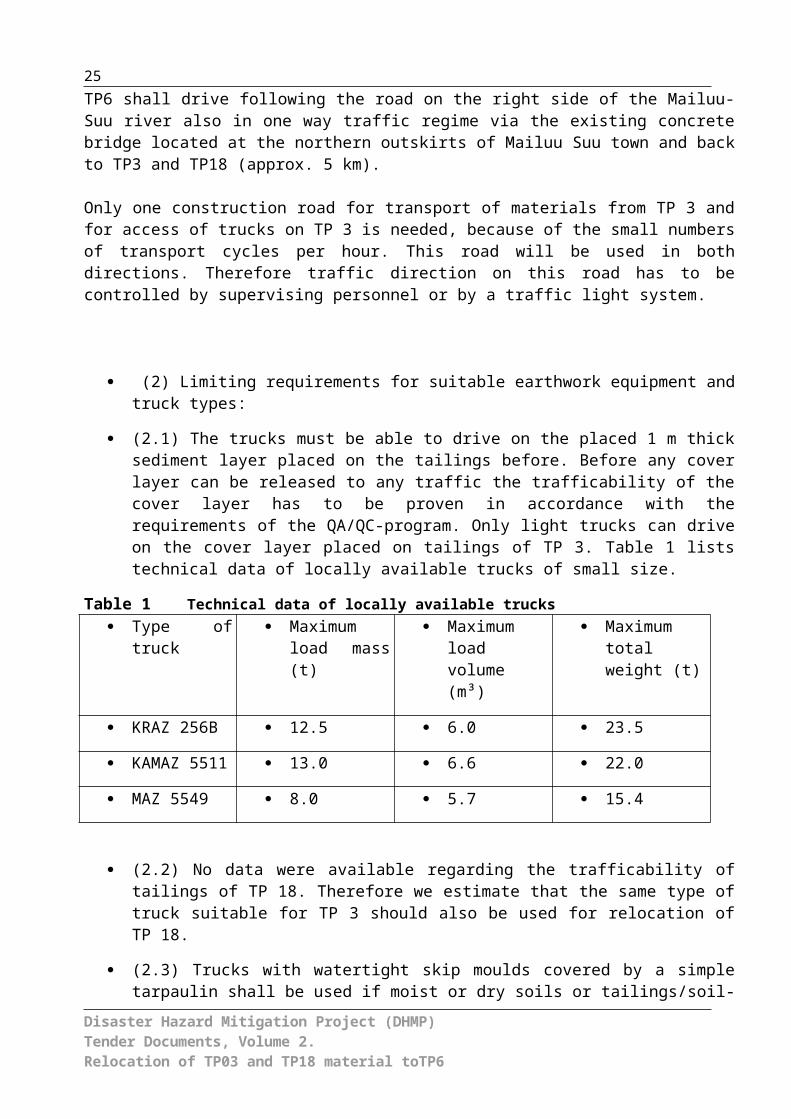
(2.1) The trucks must be able to drive on the placed 1 m thick sediment layer placed on the tailings before. Before any cover layer can be released to any traffic the trafficability of the cover layer has to be proven in accordance with the requirements of the QA/QC-program. Only light trucks can drive on the cover layer placed on tailings of TP 3. Table 1 lists technical data of locally available trucks of small size.
Table 1 Technical data of locally available trucks Type of truck Maximum
load mass (t) Maximum
load volume (m³)
Maximum total weight (t)
KRAZ 256B 12.5 6.0 23.5
KAMAZ 5511 13.0 6.6 22.0
MAZ 5549 8.0 5.7 15.4
Disaster Hazard Mitigation Project (DHMP)Tender Documents, Volume 2.Relocation of TP03 and TP18 material toTP6
18
(2.2) No data were available regarding the trafficability of tailings of TP 18. Therefore we estimate that the same type of truck suitable for TP 3 should also be used for relocation of TP 18.
(2.3) Trucks with watertight skip moulds covered by a simple tarpaulin shall be used if moist or dry soils or tailings/soil-mixtures will be transported. If the tailings mixture seems to be too soft the ratio of dry soil vs. pulpy tailings shall be increased before excavation.
(2.4) Nevertheless it cannot be completely excluded that a minor amount of fine tailings must be transported by trucks with lockable watertight containers.
(2.5) Light-weight dozers shall be used . The maximum soil pressure under the tracks of the dozer shall be maximum 27 kPa. If needed dozers must be equipped with a tool to extent the distance between shovel and the front of the dozer chassis.
(2.6) Excavators must be equipped with wide tracks. Soil pressure of the tracks shall be maximum 27 kPa. In addition the Excavator needs a minimum distance of at least 2.0 m or more to the actual excavation edge.
(3) Excavation and transport regime:
If the effective working time of the excavation works is realistically assumed to last from July till October year 1 (16 weeks = 96 working days) and from May till October year 2 (24 weeks = 144 working days), the total relocation project will take around 2 years. Interruptions of the works by rainy weather conditions are not included in the following calculation.
It is estimated that 500 m³ can be excavated and hauled per day. This results in a total working time in the first year of 96 days, with 84 - 96 truckloads per day or 7 - 8 truckloads per hour (12 hours of work per working day; working cycle 6 days per week). 12 hour of working per day means that no work breaks are included. Therefore the total shift duration per day may be even more then 12 hours.
Given proper weather conditions in the second year the total working time is 144 days including the same working regime as applied in the first year.
Excavation works are sensitive to weather conditions. In case of rainy weather the excavation works may have to be stopped.
Disaster Hazard Mitigation Project (DHMP)Tender Documents, Volume 2.Relocation of TP03 and TP18 material toTP6
19
The following table presents a calculation showing the minimum number of required equipment.
Relocation from TP 3 and TP 18 using hydraulic excavators and trucks (payload 6 m³)
period removal volume [m³ per year]
average [m³ per
year]
excavator performance
[m³/hour]
excavator daily
output[m³]
trucks ( i. e. Kamas)
loaded per hour
first year (July to October)
45,619 – 60,825 53,222 40 - 53 475 - 634 7 – 8
second year (May to October)
68,429 – 91,238 79,834 40 - 53 475 – 634 7 – 8
entire constr. period
sum:133,056 m³
For the excavation of mixture materials at least one excavator is needed all the time. The excavator is assumed to have a performance of 40 - 53 m³/hour in the first year and in the second year.
In addition at least one light-weight dozer is needed to place continuously the cover layer on air-exposed tailings surfaces. In addition we recommend to utilize at least a second dozer to doze materials from outer areas into the excavation areas in the pond centre.
The work volume of the dozers depend on the dozing distance. For this project one can conclude that the daily output of even one light-weight dozer is always above the capacitiy of one excavator The daily output of the excavator is in this case the limiting factor.
Assuming that one truck needs 30 minutes to drive the distance of 8 km per cycle and assuming the loading and unloading time including waiting times encloses in total 30 minutes then one complete transport cycle needs 1 hour. This means one needs at least 7 to 8 trucks all the time.
In the first year the estimated average relocation volume would be ca. 53,000 m³. In the second year the estimated average relocation volume would be ca. 80,000 m³.
2.4 Disposal of wastes on TP6
(1) The first construction period June-October/November year 1
(1.1) Clearing the bushes at the disposal area (2 ha)(1.2) Building a construction road at TP 6 along the ridge to the disposal area (ca. 250 m) (1.3) Construction and operation of wash trench for trucks(1.4) Construction of a safety dyke in front of the existing drainage channel (about 200 m³ compactable material) Disaster Hazard Mitigation Project (DHMP)Tender Documents, Volume 2.Relocation of TP03 and TP18 material toTP6

20
(1.5) Disposal on TP 6 (50,000 m³)(1.6) Construction of a temporary cover before winter break (7,500 m³ cohesive material)
(2) The second construction period April/May to October/November year 2
(2.1) Grouting the concrete duct (D=1000 mm, Length=50 m)(2.2) Deconstruction of the safety dyke in front of the existing drainage channel (200 m³ soil)(2.3) Removal of the temporary cover (7,500 m³)(2.4) Disposal on TP 6 (75,000 m³)(2.5) Construction of complete disposal cover (45,000 m³ cohesive material)(2.6) Construction of the southwestern drainage (Length=160 m, cross section=1.6 m², trapezoid)(2.7) Construction of the northeaster drainage (Length=250 m, cross section=0.625 m², trapezoid)
Road access for vehicles and heavy machinery to the construction site will be the responsibility of the contractor. The Site has to be equipped with minimum sanitation and living services: premises for workers and temporary water or chemical toilets. All container-type facilities are installed on the site on certain location and shifted if necessary.The construction base is the support unit for the workers, with uncovered parking lots for equipment, storehouses for materials, and living facilities on this perimeter. All these are short-term, container-type structures.The contractor shall organize and ensure necessary water and electricity supply required for civil works from nearest existing infrastructure. The site should be properly secured, including outdoor lighting and a properly maintained perimeter surface, covered with crushed stone or gravel.
2.3. Machinery and equipment used for construction- Excavator with removable equipment.- Dump trucks.- Vehicles with capacity 20 ton (maximum total weight 40 t).- Truck crane.- Screen for pebble-gravel sorting.- vibrating rollers for compaction of fill.- Sheep-foot steam-roller for compaction.- Dozer.- Ramming plate.- Light-weight dozer (CAT D4 – LPG or equal [maximum soil pressure 27 kPa])- Light trucks (KAMAZ 5511).
The type and brand of machinery and also the equipment and the quantity has to be identified by the contractor. It depends on date of work completion and his capacity. The contractor has to ensure and will be held responsible for adequacy, functionality and safety of all machinery and equipment on site.
Disaster Hazard Mitigation Project (DHMP)Tender Documents, Volume 2.Relocation of TP03 and TP18 material toTP6
21
SP 3 Engineering back-upSite supervision to ensure compliance with design will be carried during the rehabilitation works by qualified personnel of the JV Geoconsult WISUTEC (the Designer) and the Ministry of Emergencies Situations (MES), the Project Management appointed by the PIU (Project Implementation Unit).
SP 4 Scope of worksTarget of the works presented on the drawings is to relocate material from TP3 and 18 to TP6.
SP 5 Construction scheduleThe construction shall be agreed with technical activities and partly scheduled to dry season from april/may until october/november . Prior to rehabilitation works the following conditions are to be fulfilled:A) Contractor should prepare and present the Project Management or person responsible for the project for consideration the Schedule of construction that includes all elements of works which should be performed under the given Contract. The Project Management or person responsible for the project should within two weeks from the moment of official reception of it should either approve or return the schedule to the Contractor with instructions of necessary corrections according to Contract and, after all necessary corrections, the Contractor should present the Schedule of construction to the Project Management or person responsible for the project for final approval.B) Contractor before starting any construction work should submit to the Project Management or person responsible for the project the plans, drawings and installation schemes of constructions and receive the written approval from the Project Management or person responsible for the project prior to the beginning of construction.C) Equipment and machinery provided by the Contractor, as well as works executed by the Contractor, should be tested and checked according to provisions concerning elements of the works indicated in Specifications – Technical Provisions.D) After Project Management or person responsible for the project decides that construction of any part of works is completed, the Project Management or person responsible for the project should give out the written Certificate of completion of the given part of works.E) Responsibility period of the Contractor for Defects lasts twelve (12) months after receipt of Completion Certificate from the Project Management.
SP 6 Definitions1. Definitions of terms used in these Specifications are given below:a) ‘Gabion or Gabion mattresses’ - means protection structure for bank or riverbed
consisting from stone-pebble materials of certain size put into a steel net.b) ‘Reclamation’ complex of mining technical, engineering construction, irrigation measures
designed towards remediation/rehabilitation of productivity and economical value of lands damaged by mining activities.
means putting the object in compliance with requirements of norm documents, in general - rehabilitation of safety status. c) ‘Highway’ - means road with asphalted, broken stone (macadam) or concrete pavement,
which may be used in any weather. d) ‘Back road’ (field road) - means compacted earth road without paving or gravel coating,
using of this road in rainy period may demand off-road vehicle. This road is located between settlements and main roads.
Disaster Hazard Mitigation Project (DHMP)Tender Documents, Volume 2.Relocation of TP03 and TP18 material toTP6
22
e) ‘Gravel road’ - means road with gravel covering, usually between villages or main roads, passable at any weather.
f) ‘Store-and-release Cover‘ – This disposal cover (also referred to as a ‘water storage cover’, or an ‘evapotranspiration cover’) consists of one or several layers, which are designed to maximize root penetration and soil moisture storage. The cover material to ‘store’ infiltration water for subsequent removal by evapotranspiration
g) ‘QA-QC’ – Quality assurance, Quality controlh) ‘Sievert’ – (symbol: Sv) It is the unit of dose equivalent. It attempts to reflect the
biological effects of radiation as opposed to the physical aspects, which are characterised by the absorbed dose, measured in grays.
i) ‘Bequerel’ – (symbol Bq) It is the unit of radioactivity, defined as the activity of a quantity of radioactive material in which one nucleus decays per second.
SP 7 Use of soils for construction1) For organization of field services, workshops, installation of construction equipment and
other constructions necessary for works under the Contract, the Client will provide appropriate areas. If the Contractor uses private soil for additional constructions or for other purposes, the Contractor should agree upon with the owner of the soil and pay rent and all other payments connected to it.
2) Location, construction, maintenance, operation and disassembly of building constructions of the Contractor on the area given to the Client should be approved by Project Management.
SP 8 Right of passage for access and transportation proceduresThe Client will provide the right for access to places of work from existing roads. The Contractor should carry out own surveys of the status of available public and private roads, as well as sanctions, bans, restrictions on loadings of bridges and other restrictions which influence or can affect transportation and approach to working platforms and exit from them. The Contractor together with the Client are responsible for procedures on mutual agreeing necessary for ensuring special transportation and special cargoes before the beginning of construction.
SP 9 Operation and maintenance of access roadsThe Contractor operates and pays operation of routes of transportations according to the Contract in the following order:1) Transportation of materials and other internal transportations on public highways, roads
and bridges, connected with works, should be carried out according to local regulations. In places of crossing with public highways or roads the Contractor should ensure safety with the help of barriers, signalers and other necessary safety measures.
2) Payment to the Contractor of the works under the given subsection should be included in other clauses of works of the Bill of Quantities.
SP 10 Transport route during relocation/ Construction of roads crossings
A part of the transport route between TP3/18 and TP6 along the left bank of the Mailuu-Suu-River and between TP6 and TP3/18 along the right bank of the Mailuu-Suu-River will be used as a public road at the same time. There have to be paid special attention for Disaster Hazard Mitigation Project (DHMP)Tender Documents, Volume 2.Relocation of TP03 and TP18 material toTP6

23
protecting the member of the public traffic, the routes have to stay clean and there have to be made a dust suppression.
Crossing motorways and roads is carried out in view of the following requirements:1) Traffic area of the road should remain open for traffic, or the Contractor should provide
temporary road line. The road pavement dug, removed or damaged during the works of the Contractor, should be restored with use of the same materials and in dimensions, which covering had initially. The way which the Contractor will restore the traffic area should be approved by the Project Management.
2) Payment to the Contractor for maintenance and service of routes of transportations and roads, including removal of existing pavement of traffic area and other road accessories and its restoration at construction of pipelines that cross traffic area of roads, should be included in tender costs of other points of the Bill of Quantities.
SP 11 Access for implementation of topographic surveysProvision of the Contractor with access to implement topographic surveys is fulfilled with account of the following requirements: 1) The Contractor notifies in written form the Engineer about provision of the Contractor with
right to have access to implement surveys for construction.2) The Contractor notifies in written form the Client that he may start implementation of
preparation survey for construction.
SP 12 Works within the right for accessThe following Provisions relate to remediation works at the tailings sites under the Contract within the rights for passage and access:1) According to given specifications, territory provided within the right for access and
passage for construction works can be on or near developed area. In those places where channels pass near, cross or touch the developed area, namely the vegetable gardens, forest plantations, irrigation and drainage constructions, sown and reclaimed area, the Contractor should carry out works trying to minimize damage to these developed areas..
2) All works of the Contractor on construction of new riverbed, roads, and tailings remediation including storage of materials, excavations, clearing and restoration of soils used for passage, should be executed in such sequence and with such equipment and means that ensure completion of each part of works according to provisions of the Contract.
SP 13 Restoration of soils used for passage1. The following provisions relate to restoration and payment for restoration of soils used
for passage on territory of the economies: а) The Contractor should restore a surface of soils affected due to the right for passage at works on construction of a new riverbed and during works as close as possible to the initial status, according to the given Specifications – Technical regulations so that the result is satisfactory to Project Management.b) Payment to the Contractor for all works described in the given point should be included in the prices offered under other points of the Bill of Quantities.2. The following provisions relate to restoration and payment for restoration of road
coverings:а) The Contractor should restore traffic area affected at works within the right for passage as close as possible to initial status according to given Specifications – Technical Provisions.
Disaster Hazard Mitigation Project (DHMP)Tender Documents, Volume 2.Relocation of TP03 and TP18 material toTP6
24
b) Payment to the Contractor for all works described in the given point should be included in the prices offered under other points of the Bill of Quantities.
SP 14 Communications, electric power transmission lines and telecommunications
Location of underground communications, power lines, telecommunications and others will be given on drawings and layouts. The Contractor should pay appropriate attention during construction to ensure safety of communications.
SP 15 Safety planThe Contractor should strictly follow safety rules for people and machinery during time of construction, and on safety rules issues the Contractor should operate under the existing legislation of the Kyrgyz Republic.а) The Contractor should protect people working in trenches from collapsing of walls through construction of retaining casing or setting slopes in accordance to provisions of the Contract and watch the people not to work in trenches alone.
b) The Contractor should protect personnel from moving parts of machinery with help of correct installation and maintenance of safety casings.
c) The Contractor should not allow casual observers to come close to excavation sites.
d) Appropriate measurements of the ambient gamma dose rate and radioactive dust have to be performed which will serve as basis for the calculation of effective doses of the workers. For these measurements, qualified personnel and a qualified subcontractor has to be included.
SP 16 Clearing of operation areaThe Contractor should constantly prevent to clutter up the construction site, including storage yard, with materials or waste products. SP 17 Utilization of wasteWaste utilization will be done by the following manner: a) Utilization of waste is meant, but not restricted, defective goods, garbage, trash, industrial
waste, also oil and oil products, is under the Contractor’s responsibility. The waste utilization has to be done by deposition to the locations, where burning of these are permitted in conformity with legislation of the KR, or by removal from the site.
b) All wastes, utilization of which is assumed by burning, have to be stacked in proper place for burning thus to minimize fire risk. The burning has to be made thoroughly and fully, and all pieces charred left after burning are to be removed form the site and utilized by other methods described in this item. The Contractor shall constantly undertake special safety measures to prevent fire distribution from piles burnt and shall be responsible for any damage caused by his burning activities.
c) Wastes subject to utilization by removal from the site have to be utilized prior to completion of works in compliance with these Specifications. All wastes, which are supposed to dump, shall be transported to appropriate dump deposit. The Contractor shall undertake all respective agreements.
SP 18 Preservation of landscapeThe Contractor should take appropriate measures to preserve natural landscape and carry out construction works in such manner to avoid any unnecessary destruction, damage and Disaster Hazard Mitigation Project (DHMP)Tender Documents, Volume 2.Relocation of TP03 and TP18 material toTP6
25
break of the environment on works site. Except for places where clearing is necessary for permanent works and construction roads, all trees, bushes, vegetation, fences and walls should be saved and protected from damage that can be caused by construction, restoration works or by the equipment of the Contractor. Movements of people and equipment across the area on which there is a right for passage, and cross the routes provided for access to works places, should be made in such manner to minimize damage to pastures, agriculture or other property.
SP 19 Prevention of water pollutionThe Contractor should follow acting rules on control and reduction of water pollution:
а) The Contractor should make constructions in such a way to prevent coming and falling of solid substances, pollutants, debris and unacceptable polluting agents into streams and underground sources. The waste is to be reclaimed by deposition into earth at sections agreed, or other agreed methods.
b) The Contractor will provide its personnel with appropriate sanitary constructions.
SP 20 Temporary settlements of the ContractorTimely settlements of the Contractor should comply with regulations on timely settlements issued by Ministry of Health of the Kyrgyz Republic and to requirements specified there.
SP 21 Survey dataSurvey data and data on benchmarks (reference points) will be provided to the Contractor by the Project Management. The Project Management provides the results of survey, the list of benchmarks and reference points for construction of the new riverbed and structures on this. Direction, length, depth, approximate location, slope and benchmarks of the area are shown on the drawings of design works. The Client should also provide the corresponding information concerning access right of the Contractor on area that does not belong to him so that the Contractor could determine an arrangement of routes for reception of the passage right at carrying out construction survey on works which should be executed under the contract. The Client will support necessary communication with farmers.
SP 22 Construction surveysConstruction surveys for field location will be done by the Contractor based on benchmarks and data, provided by the Project Management, in accordance with sub-item 1 of this item. The Contractor should set up all contours and slopes of sections required for work supervision, and will be responsible for all measurements of contours, slopes, and dimensions required for work implementation within deviations prescribed in these Specifications or indicated on Drawings. In the cases, when it will be requested by the Project Management, surveys and records shall include, but not limited:a) All field recordings, calculations and other data received during survey, including the data
on perpendiculars and contours and repeated trace of profiles of axial lines, should be registered by the Contractor in field book for subsequent presentation. All survey data should be clearly written in the format authorized by Project Management so that it can be verified. Illegible recordings or erasures in field books are not allowed and the Contractor can be demanded to repeatedly perform survey of those sites where data were written illegibly down or erased.
Disaster Hazard Mitigation Project (DHMP)Tender Documents, Volume 2.Relocation of TP03 and TP18 material toTP6
26
b) All field books should be numbered and have cross references. Field records, brief reports, recordings and calculations by the Contractor during necessary surveys should be available so that at any moment during works the Project Management could check them. After completion of works, the Contractor should give all materials on surveys of the area to Project Management and these materials become property of the Client.
c) All works on control carried out by the Contractor should be with degree of accuracy specified in the Contract.
d) Survey of the area by the Contractor should include installation of pegs or other marks for measurement of heights for definition on the location and marks of the surface, all changes of slope necessary for shifting the channel. Surveys of marks of the soil should be done with the maximum interval of 50 meters along river bed or with smaller intervals if Project Management demands.
e) The Client can demand to suspend works at any time if the Contractor does not set benchmarks according to the ordered accuracy. The Contractor has no right for any increase in time of works, as well as to make any claims in connection with damage or additional costs connected to such suspension of works. Suspension of works is cancelled in case of correct installation or specification of all reference points.
f) If during field survey for construction there are any difficulties or for any other reasons Project Management needs to reconsider trace or marks of the whole or any part of river shed in the initial drawing, Project Management should carry out repeated topographic survey of this area and reconsider, if necessary, the drawings. At final field survey for construction scheme the Contractor should use these reconsidered drawings. Such final field schematic developments are not paid to the Contractor.
g) The Project Manager is responsible for drafting of as-built drawings (final survey) and respective required investigations.
SP 23 Ensuring personnel and equipment for investigationsThe contractor is responsible for ensuring equipment and personnel necessary for investigations and it will occur as follows:a) The Contractor should provide at own expense columns, poles, steel pins, patterns, all
equipment for survey and other equipment, tools, transport and materials, including field books necessary for required investigations. After completion of the task the Contractor should clear the area, including removal of all columns, poles, pins and other materials used for the works charged to him.
b) All expenses for investigation according to the procedures provided in the given paragraph should be included in costs of material declared in the Bill of Quantities and necessary for various works within the task.
SP 24 Reference specifications and standards for materialsa) The basic requirements to standards and specifications of the materials are provided by
the Client:b) Materials provided by the Client and installed by the Contractor in accordance to the
Contract, determined by references to standard specifications and codes, should correspond to last versions of these standards, including any specifications, additions and changes acting on the date of reception biding applications. In case of incompliance to requirements of specifications, standards or codes referred, to Special Provisions and Technical Provisions, it is necessary to adhere to requirements of given Special Provisions and following further Technical Provisions.
c) If it is not determined differently, all materials used during construction and becoming construction component should be new and correspond to specifications and standards
Disaster Hazard Mitigation Project (DHMP)Tender Documents, Volume 2.Relocation of TP03 and TP18 material toTP6

27
referred in the given document. In case specifications for the given material are absent, delivered materials should be of standard trading quality
SP 25 Responsibilities of the ContractorThe Contractor shall provide and store all construction materials for work implementation under the Project, and also bind himself to provide transport maintenance and temporary depots in-situ. He has to guarantee, that quality of specifications will not change during transportation and installation of equipment and materials. The Project Management keeps right to reject some or all materials, which do not meet the Specifications. The Contractor should protect all materials against damage during transportation, short-term storage, and supply. Payment to the Contractor should be included in a unit of the Bill of Quantities on examination, checking, transportation, timely storage and delivery of the equipment and materials necessary for performance of works under the Project.
SP 26 Mobilization and preparationsMobilization payment (Advance Payment) is to be performed in accordance with the Main Terms of Contract for compensation of current expenditures of the Contractor, including, but not limited, any mobilization costs of equipment, implements, and stocks, and also supply towards place of installation; required costs for advance payment and dislocation of staff, required house equipment, stocks and implements to the Project site and back; site preparation, organization of workshops, storehouse, administrative and living premises, services and other offices, which are considered as necessary arrangement; payment of promissory notes and insurance rates required according to the Contract, and other works and actions, which should be implemented, expenditures to be incurred before rehabilitation works.
SP 27 Mobilization paymentsPayment to the Contractor for Mobilization and preparation work is done according to provisions of the Basic Conditions of the Contract.
SP 28 Substantive provisions on rating and paymentPayments will be made according to the procedures stipulated in the Basic Conditions of the Contract as it is described further. Payments will be made on Contract prices for the points accepted in the Application, as defined in abovementioned Technical Provisions. For works required by Special Provisions and General Provisions of the Contract; separate payment will be made only in case it is specially stipulated under the given point in the Bill of Quantities.
SP 29 Rating for paymentFor payment of clearing and excavation all measurements of cross-sections and other necessary measurements will be executed before the beginning of works. These measurements will be made repeatedly, and the difference between them will be a basis for payment. The rating of payment on contract costs of tasks will be carried out by Project Management based on actual amounts of executed works or materials delivered with the help of the method of rating established in Specifications. When the volume estimated for payment under one task relates to volume estimated for payment under different task, the Project Management should determine the exact dividing lines marking start and completion of volume under each task. Except for cases separately determined in Points of the
Disaster Hazard Mitigation Project (DHMP)Tender Documents, Volume 2.Relocation of TP03 and TP18 material toTP6

28
Contract, rating of payment will be made only on volumes of materials established or removed according to requirements on performance of the accepted part of works. The excavations and construction equipment and other works implemented by the Contractor at the choice for own purposes, will not be estimated for payments.
SP 30 PaymentsThe amount of payment to the Contractor, based on actually executed scope of works, which is determined by the Project Management with the help of the method of rating established in Specifications, and based on prices stipulated under the Contract, is full payment of the whole work presented in Drawings envisaged in Specifications or Contract Documents, or naturally read from contents of a part of Contract Documents and contingencies, as well as acceptance by the Contractor of risk, responsibility and obligations stated or implied in Contract Documents. The Contractor should make certain work for certain payment without dependence, whether the given work was concerned specially or included in other way, to certain point of the Bill of Quantities.Payments on all points should include, but not necessarily limited, the payment of ensuring installations, control, workers, equipment, overhead expenses, profit, materials and services; and performance of all works determined by each point, and all other works required by Contract Documents.
SP 31 Contract drawingsUnder the contract drawings are to be executed. The specific number and type of drawings will be taken into account during bidding and are listed in the List of Drawings, further referred as Tender Drawings. These Tender Drawings reflect the scope of works which the Contractor should execute.
SP 32 Construction drawingsThe Contractor will be provided with working drawings in full after the Contract signing.
SP 33 Definition of the terms “Drawings”The term “Drawing” used in Specifications is applicable both to Tender Drawings determined in subpoint SP – 32 of Special Provisions “Contract Drawings” and to Drawings developed for construction described in subpoint SP – 33 of Special Provisions as Drawings developed for construction.
Disaster Hazard Mitigation Project (DHMP)Tender Documents, Volume 2.Relocation of TP03 and TP18 material toTP6
29
Part II. Technical Instructions
Disaster Hazard Mitigation Project (DHMP)Tender Documents, Volume 2.Relocation of TP03 and TP18 material toTP6

30
Part II. Technical InstructionsConstruction ActivitiesSP 1 General..........................................................................................................8SP 2 Description of works......................................................................................9SP 3 Engineering back-up...................................................................................21SP 4 Scope of works............................................................................................21SP 5 Construction schedule.................................................................................21SP 6 Definitions...................................................................................................21SP 7 Use of soils for construction........................................................................22SP 8 Right of passage for access and transportation procedures.......................22SP 9 Operation and maintenance of access roads..............................................22SP 10 Transport route during relocation/ Construction of roads crossings...........22SP 11 Access for implementation of topographic surveys.....................................23SP 12 Works within the right for access................................................................23SP 13 Restoration of soils used for passage.........................................................23SP 14 Communications, electric power transmission lines and telecommunications
....................................................................................................................24SP 15 Safety plan..................................................................................................24SP 16 Clearing of operation area...........................................................................24SP 17 Utilization of waste......................................................................................24SP 18 Preservation of landscape...........................................................................24SP 19 Prevention of water pollution.......................................................................25SP 20 Temporary settlements of the Contractor....................................................25SP 21 Survey data.................................................................................................25SP 22 Construction surveys...................................................................................25SP 23 Ensuring personnel and equipment for investigations................................26SP 24 Reference specifications and standards for materials................................26SP 25 Responsibilities of the Contractor...............................................................27SP 26 Mobilization and preparations.....................................................................27SP 27 Mobilization payments.................................................................................27SP 28 Substantive provisions on rating and payment...........................................27SP 29 Rating for payment......................................................................................27SP 30 Payments....................................................................................................28SP 31 Contract drawings.......................................................................................28SP 32 Construction drawings.................................................................................28SP 33 Definition of the terms “Drawings”...............................................................28CONSTRUCTION ACTIVITIES...............................................................................................32Section 1. Plan of location and of construction equipment of the contractor..............33Section 2. The Engagement of civil works..................................................................33Section 3. Breakdown and control topographic works................................................33Section 4. Materials provided by the Contractor.........................................................36Section 5. Materials and quality..................................................................................36Section 6. Recommended specifications and standards............................................37Section 7. Access roads to working sites and routes of transportation......................37Section 8. Use of soils for construction purposes.......................................................38Section 9. Operation and maintenance of access roads.............................................39Section 10. Existing protection fences..........................................................................39Section 11. Electric power transmission lines...............................................................39Section 12. Ensuring traffic of public transport..............................................................40Section 13. Protection of immovable property locating along access roads to working
sites.............................................................................................................40Section 14. Construction on existing water-currents and communications....................41Section 15. Right to change the site and plan................................................................42Section 16. Geological investigations............................................................................42Section 17. Safety plan..................................................................................................42Section 18. Preservation of vegetation..........................................................................43Disaster Hazard Mitigation Project (DHMP)Tender Documents, Volume 2.Relocation of TP03 and TP18 material toTP6
31
Section 19. Protected plants and animals......................................................................44Section 20. Prevention of water pollution.......................................................................44Section 21. Preservation of historical and archeological monuments............................45Section 22. Clearing and waste disposal.......................................................................46Section 23. Water Drainage and protection of water-currents during construction........47Section 24. Technical Specifications for “Reno” mattresses..........................................48Section 25. Technical Specifications for reconstruction of existing Roads....................49Section 26. Reconstruction of existing Bridge................................................................49Section 27. Technological roads....................................................................................49Section 28. Water treatment facility...............................................................................50Section 29. Truck wash plants.......................................................................................50Section 30. Drainage Systems for surface dewatering..................................................51Section 31. Rain storage reservoir.................................................................................52Section 32. QA/QC Program..........................................................................................52Section 33. SRC cover...................................................................................................53EARTH WORKS 54Section 34. Specifications for earth and stone works....................................................55CONCRETE 63TECHNICAL CONDITIONS AND SPECIFICATIONS............................................................63Section 1. Concrete......................................................................................................64Section 2. Main requirements to concrete....................................................................64Section 3 Cement........................................................................................................65Section 4 Sand............................................................................................................67Section 5 Coarse aggregate.......................................................................................69Detrimental impurities.............................................................................................................70Section 6 Water...........................................................................................................71Section 7 Concrete quality control measures and concrete quality test program.......72Section 8 Deviations of Facilities and surface tolerances for concrete structures......73Section 9 Preparation for concrete laying...................................................................76Section 10 Concrete laying..........................................................................................78Section 11 Dosage.......................................................................................................81Section 12 Mixing.........................................................................................................83Section 13 Temperature of concrete............................................................................85Section 14 Concrete curing measures.........................................................................86Section 1 Formwork, General.....................................................................................88Section 2 Formwork casing and Facing......................................................................88Section 3 Uniformity of formwork material..................................................................90Section 4 Finishing and finishing works......................................................................91Section 5 Molded surfaces..........................................................................................91Section 6 Unmolded surfaces.....................................................................................92Section 1 Reinforcement bars, general.......................................................................94List of Drawings 100
Disaster Hazard Mitigation Project (DHMP)Tender Documents, Volume 2.Relocation of TP03 and TP18 material toTP6
32
CONSTRUCTION ACTIVITIES
Disaster Hazard Mitigation Project (DHMP)Tender Documents, Volume 2.Relocation of TP03 and TP18 material toTP6

33
Section 1. Plan of location and of construction equipment of the contractor
Within 21 days after signing the Contract, the Contractor should surrender to the Project Management designs showing concepts of arrangement and construction equipment, which are used for construction and for working realization in-situ.
General location of construction facilities for example storehouses, depots, production platforms, parking vehicles of workers, first-aid unit, temporary access roads, platforms of processing and recycling of waste.
The Contractor will provide a disc and two hard copies of each measure. One hard copy with remarks of the Project Management should be returned to the Contractor.
The expenditures for realization of every work under this section should be included into the items of BOQ related to types of works of which they are.
Section 2. The Engagement of civil works
a) Map with altitude markings. – The Project Engineer establishes a map with altitude markings which are used for adequate working performances.The Contractor assists and provides with materials which the Project Engineer may need for establishment. The Contractor organizes the construction work in such terms, which will be necessary for rendering assistance.The Project Engineer only provides the required minimum of topographical works. People who are responsible for topographical works cannot be involved the whole time for works according to the given specifications. The Contractor briefs permanently the Project Engineer of the necessity of topographical works and coordinates it with the basic works of the Contractor.
b) Substitution of bench marks. – The necessity of removing bench marks or other topographical marks by the Client during construction work decides the Contractor in established order. Topographical marks which are established by the Project Engineer are stored by the Contractor until receiving to the Authority to cancel them. In case of cancellation or destruction by the Contractor, the Project Engineer changes them at the expense of the Contractor.
d) Expenses for providing all necessary materials and performances of all works are required by Project Engineer. That obtains also breakdowns which are described in the given section and are included in the Bill of Quantities for all kinds of works of which component they are.
Section 3. Breakdown and control topographic works
a) General provisions – The Contractor is performing all topographical works and breakdown which is necessary for verifying and completion. Moreover all required topographical works which belongs to quantitative measures of scope and executed works.
The Project Engineer establishes a primary supervisor.
Disaster Hazard Mitigation Project (DHMP)Tender Documents, Volume 2.Relocation of TP03 and TP18 material toTP6

34
Primary supervision includes designing and altitude marking close to the site of works as described and shown on the drawing. Before the beginning of works the Contractor verifies the primary supervision. All discrepancies are verified prior to the beginning of works.Project Engineer provides complete list and an identification of the primary supervisor within 45 days after receiving a note of starting works.The Contractor keeps detailed marks of the primary supervisor before he receives another order. Marks of primary supervisor which are deleted before any acceptance by the Contractor in case of responsibility related to their safety, can be replaced by the Project Engineer. Charges for recreation are to be take off from the amount due or to be paid to the Contractor.The Contractor introduces professional geodesists. A topographical survey will be done under supervision. The geodesist must have a minimum operational experience about 2 years. In the field the Contractor provides the qualified workers who do the necessary performances for topographical work.Every kind of survey work attached by the Contractor is to be verified by the Project Engineer in-situ and at the office. Not less than 40 days prior works will be started, the Contractor submits a complete plan of survey works to the Project Engineer. It contains the mode of operation works, a work schedule plan and an altitude breakdown.Not less than 40 days prior at the beginning of topographical works the Contractor presents the CV confirming the topographer´s qualifications and experiences. He is responsible for supervision and management works of the Contractor. In case of his replacement a new nominee who is authorized is presented not less than 40 days prior to the replacement.At least 40 days prior at the beginning of topographical works the Contractor presents after verifying the authorization the primary supervisor established by Project Engineer and carried out by the Contractor.Within 2 days after finalization of topographical works the Contractor presents respective materials for reviewing and documentation. After compiling the documents of field topographical works, the Contractor delivers an original journal of reviewing and documentation within 2 days. Together with applications for progressive payment the Contractor surrenders materials of recordings of a quantitative rating, calculations and specifications of topographical works executed during the determined period for approval.On request by the Project Management the Contractor surrenders a copy of the topographical working information for reviewing and documentation for one working day.
b. Breakdown of work – Based on the altitude markings of primary supervisor established by the Project Engineer the Contactor is responsible for all measurements which can be necessary for working performances under permitted tolerances which are provided in the specifications or designs. The Contractor establishes places and if necessary the changings of additional landmarks, reference points and other altitude markings which are necessary for controlling, intermediate verifications and construction works.
c) Controlling of topographical works – The Contractor does every kind of topographical work and calculation which are used for the definition of the working scope. It is executed during each period and will be submitted for the payment. If necessary he surrenders it to the Project Engineer. The Project Engineer’s decisions are based on primary territorial data established by the Client and on topographical data of the Contractor.
Disaster Hazard Mitigation Project (DHMP)Tender Documents, Volume 2.Relocation of TP03 and TP18 material toTP6

35
Not less than 24 hours prior at the beginning of investigations, unless nothing else is decided, the Contractor advises the Project Management. The controlling topographical works are delivered in attendance of the Project Engineer.
d) Topographical survey
(1) Required topographical works, which contain all items of the project, roads, and hedroengineering structures. (а) Establishment of landmarks: Settings every 25 meters straight at the road and every 10 meters at twisting roads.(b) Breakdown of slopes by markings: Settings every 25 meters straight at the road, every 10 meters at twisting.(c) Constructions: Breakdown of constructions and their controlling is completed before and during construction.(d) Road: Deep reference markings are set every 25 meters straight ahead and every 10 meters at twisting site of the road.(e) Diameter: Initial, final and intermediate diameters are set, according to requirements, along the alignment of construction. Moreover it is necessary for controlling. (f) Modeling: Any required topographical works for modeling for example preparation and design or any other actions are carried out by the Engineer.
(2) Accuracy: Degree of accuracy should be high enough and respond to the followingpermitted tolerances:(а) Alignment of straight lines and bends should be within 30 mm.(b) Marks of constructions should be set within 3 mm.(c) Deep reference points are set within 3 mm.(d) Marks of the diameter should be within 3 mm on horizontals and verticals. Vertical marks should be within 10 mm.(f) Materials and equipment. – Contractor should dispose all materials and equipment which is required for topographical works. That includes: tools, marks, crutches, steel pins, basic plates, platforms and other appliances. The whole equipment and materials will remain to the Contractor except things which will be part of the construction or be left in place.Tools should be accurate. The accuracy will be exposed by carefully testing at least every two weeks. Broken tools, only if the Project Management knows about it, should be urgently replaced, repaired or fixed to bring it into compliance with the requirements of Project Management.
e) Accountability
Data of topographical works should be taken into the report according to the professional standards of topographical works. Primary field recordings, calculations and other data are registered in field books of the Contractor approved by the Project Engineer. Recordings or data which do not corresponding to standard forms have to be rejected. Illegal recordings or data, the erasure of any page of the field book is a sufficient reason for rejecting a part from the book or the whole book. Duplicates of recordings or data are unacceptably. Therefore rejection of a part of the book or the whole field book, the survey can be retaken in case of any demand. Any errors can be adjusted. Keeping the book and recordings of topographical works is unacceptable.
Disaster Hazard Mitigation Project (DHMP)Tender Documents, Volume 2.Relocation of TP03 and TP18 material toTP6
36
f) Expenses
Expenses for all materials, equipment and workers which are necessary for topographical surveys especially at the case of breakdown and the controlling of topographical works are included in points of the Bill of Quantities based on works of which component they are.
Section 4. Materials provided by the Contractor
a) General
The Contractor provides all materials which are required for working performances. The word “Material” or “Materials” is used in the given specifications for marking of points provided by the Contractor and represents equipment, machinery, production, component or any other point for performance of works.
If a certain item includes the supply of any kind of material, it will be decided in the Bill of Quantities. Moreover efforts like for example delivery ,transportation and storage are included in the charges of the proposal. If this point is not be determined in the schedule of deliveries by the Contractor, expenses for its delivery, transportation, storage or maintenance will be included in the working charges of the .proposal
Materials which are provided by the Contractor, should agree to type and quality which is submitted in the specifications. The Contractor should endeavor the ensuring of deliveries of the specified materials from every possible sources. But if materials which are required to the present specifications, are inaccessible there can be substitutes. They will not be used without preliminary written approvals of the Project Management, in which change of the amount, if it takes place, is approved for the benefit of the Client. Decisions of Project Management on replacement of material and on what substitutes can be used, is final and ultimate. If the approved substitutes are of smaller values for the Client or include less expenses for the Contractor than those will be determined by specifications. Changes are inputted by the benefit of the Client. Changing amount and justification for substitutes are reflected in the contract. There must not be any additional payments owing to replacement of one material with another one or using one kind of material instead another.
b) Check of materials. – Materials delivered by to Contractors, which will become a part of the complete construction, are exposed by verifying according to points 15 and 16 of Conditions of the Contract. In any places determined by the Project Management: in places of production, processing, loading or work. For ensuring sufficient time of verifying, on date of delivery the Contractor should provide the Project Management three copies of orders for procurement which includes drawings and other required information of checked materials chosen by the Project Management. Moreover offering other confirmations of materials in any of above-stated places, or refusal of their checking is not regarded as the conclusion about compliance of materials and equipment to contract provisions, and does not relieve the Contractor from responsibility for compliance of delivered materials to requirements of the present specifications. Reception of all materials is carried out only in the place of work.
Section 5. Materials and quality
а. MaterialsAll materials supplied by the Contractor should be the latest and corresponding quality, including durability, plasticity and best engineering quality.
Disaster Hazard Mitigation Project (DHMP)Tender Documents, Volume 2.Relocation of TP03 and TP18 material toTP6

37
Section 6. Recommended specifications and standards
Materials, designed by the Contractor, construction works and other requirements are determined similar to the Kyrgyz or International Standards, or other standard specifications and codes. They should accord to the latest and revised editions acting at the moment of reception of the proposal, including all corrections and additions. In case of contradictions between recommended specification, standard or code and present specifications, the latter are deciding.Until other specifications are not defined, all materials which become a part of the completed construction should be new and correspond to international standards or other mentioned specifications or standards. Where types, classes or other parameters of the materials proposed are not reflected in the present specifications, the material supplied may be accepted if it corresponds to any of the parameters proposed. Copies of corresponding Specifications of the Kyrgyz Republic can be received in the address: Agency of Architecture and Construction, 28, Manas St., Bishkek, Kyrgyz Republic, Tel. 217432, fax 217553 or Department of Water Resources, #4a, Toktonaliev St., Bishkek 720010, Kyrgyz Republic.The Contractor on the site of works should have copies of all specifications, standards, codes, manuals and other documents recommended by the present specifications and concerning to materials used for work for that time. Copies should be accessible for use by Project Management and his representatives.Note: References of materials, the production mark which appears in trading specifications under a special title, are only made to compare types, characteristics and necessary qualities of the product, and do not limit suppliers. The Contractor is responsible for the materials identity for supplying. It is recommended to present specifications and should ensure all descriptive information, testing results and other bases which can be necessary for identification of materials proposed by the Contractor.
Section 7. Access roads to working sites and routes of transportation
а. General provisionsAccess roads right to structures from existing roads is provided by the Client according to provisions of SP-8, SP-9, SP-10, SP-11 of Specifications – Special Provisions. All works related to access roads are required to the sites which are realized by the Contractor.
Independently from others the Contractor carries out an investigation to verify the conditions of available public or private roads, the dimensions of restrictions, the maximum loads on bridges, road junctions and other restrictions which influences transportation, departure or entrance to the construction site. The impracticability of transporting equipment or restrictions cannot be excuses for delays refered to the completion of works. Construction and maintenance of roads, access roads, bridges required for carrying out of construction works, are made by the expense of the Contractor.b. Existing roadsExisting roads are accessible for operation by the Contractor in view of existing restrictions. Activities of the Contractor should meet all provisions imposed by the legal owner on use of existing roads, including seasonal or other restrictions, payment for excess of allowable sizes and loadings, as well as payment of repair works arising as a result of damage of the road pavement caused by the Contractor.c. Routes of transportations
Disaster Hazard Mitigation Project (DHMP)Tender Documents, Volume 2.Relocation of TP03 and TP18 material toTP6

38
Transportation of sand, gravel, soil and other materials along public highways, roads or bridges is carried out according to local normative documents and should not overload local traffic stream. Where transportations routes cross public highways or roads, the Contractor provides road junctions, unloading of transport, adjustment and other required preventive measures for the local public.
d. ExpensesExpenses for all works described in the present paragraph are included in corresponding points of the Bill of Quantities on every kind of work which is part of them.
Section 8. Use of soils for construction purposes
а. General provisionsContractor should receive a permission of using client´s land which is controlled by the owner,for temporary construction of administrative buildings, roads, dumps and other construction platforms necessary for the purposes of construction.If private land is used for building sites or other purposes of construction, the Contractor should make all required agreements and should pay all relevant rents and other expenses.b. Documents submitted for approvalSubmitted documents should respond to the present paragraph and paragraph “Documents submitted for approval”.At least 30 days prior to use Client´s land for purposes of construction, the Contractor should submit a landscape design of reconstruction each site of public´s land by the Contractor, including environment protection and cultural license. Each landscape design of reconstruction should contain the following:
(1) Designs showing location and degree of utilization of the site by the Contractor. Designs of office buildings, platforms for storage, including places for storage of the combustive-lubricating products, assembling sites, parking of mechanical machinery, timely access and transport roads, platforms for processing should be specified, as well as storages, burial places of waste products of construction, platforms for explosive storages if there are blasting works, timely fences and other land use of the Customer by the Contractor, including information required for Contractor´s confirmation of using the allocated land.
(2) Description of working methods used by the Contractor for:(а) Preservation of protection fences and restoration, in case of vegetation destruction (trees, bushes and grass) and other landscape elements on construction site or in adjacent area which cannot be relocated, according to the agreement, are damaged, including methods of marking of borders of site of works, protection of damaged sites and prevention of erosion.(b) Protection from destruction and, in case of destruction, the reconditioning of the existing housing economy close to and at the site of works. Their arrangement is necessary to brief the Contractor.
(3) Designs and written descriptions of the Contractor´s methods for carrying out of reconstruction of working site, construction finalisation, removal of temporary constructions of the Contractor and clearing of the site.(c) Land of the ClientThe use of Contractors land of the Client for construction purposes is carried out according to requirements of the Contract, the present specifications and requirements of this section. Such use should not disagree to any part of works corresponding to the Contract, or to works of other contract organizations.
Disaster Hazard Mitigation Project (DHMP)Tender Documents, Volume 2.Relocation of TP03 and TP18 material toTP6

39
Section 9. Operation and maintenance of access roads
а. General provisionsAfter the construction of access roads, platforms of service and parking of machinery, they will be used by the Contractor for the whole construction period under the present contract. The Contractor keeps the road paving in good condition before working completion under the present contract. Right after the first performance of road construction the Contractor should put an additional covering on the access roads, platforms of service or parking of machinery. Removing of snow or assistance to working performance by the Contractor is considered as a part of usual activity on maintaining roads.b. ExpensesExpenses for service of road covering, culverts, constructions, road pavement and repair of damages described in the present paragraph should be included in relevant points of the Bill of Quantities on every kind of work which is part of them.
Section 10. Existing protection fences
Protection fences on access roads which disturb working performances have to be dismantled by the Contractor. Moreover they have to be restored in proper order if it´s required. In marked sites the protection fences are saved before completion of works and reception of permit for their demolition. In case of demolition by the Contractor of existing protection fences, for working convenience, to the adjacent areas and access roads, for the whole period of Contract validity, temporary fences have to be build. Such temporary fences protect territory from cattle of neighboring area. They should have gates and/or fences against cattle. The temporary protection fences constructed on access roads, are demolished by the Contractor before final acceptance of the completed work.If the Contractor does not provide required protection fences, fences for cattle or for protection of property the Project Management Deducts the charges of the Contractor´s payment in case of any occurrence. Expenses for all works under the present paragraph are included in corresponding points of the Bill of Quantities on those works which component they are.
Section 11. Electric power transmission lines
а. General provisionsContractor provides and performs all required works according to the Contract. Works are the service of electric power transmission lines and water supply which exist at the moment of Contract reception. Every work should be carried out in high quality and be satisfying the owners/ operaters of communication system, as well as Project Management. Moreover it should include maintenance and service of every required (observation unit, alarm unit, protection fences) temporary construction, any necessary repair, replacement and similar operations, payment of required compensations or other liabilities.Construction-assembling works in the conservative zone of working electric power transmission lines should be done with a written permission of organization-owner of the line and access order, prescribing safe conditions of work and issued in conformity with regulations SNIP 12-01-99. b. ExpensesExpenses for all works under the present paragraph are included in corresponding points of the Bill of Quantities on works by which component they are.
Disaster Hazard Mitigation Project (DHMP)Tender Documents, Volume 2.Relocation of TP03 and TP18 material toTP6

40
Section 12. Ensuring traffic of public transport
а. General informationThe contractor ensures keeping traffic of public transport and carries out construction of roads, bridges, channels, not creating inconveniences to traffic of public transport. Convenient access to roads and residential buildings are ensured along sites of works, and temporary entrances to crossroads and crossings of roads are maintained in good condition. The public transport is authorized to pass and cross a place of construction at any time with minimum inconveniences and delays. The contractor, in case of receipt of the order, gives the competent traffic controller responsible for the control and adjustment of movement of public transport through and around the site.Where the public transport appears to cross or move through the site of construction works, works on alignment, clearing, humidifying and ensuring unobstructed two-way traffic of public transport at any time are provided. Where necessary, the contractor equips temporary traffic junctions between existing roads and new construction. Everywhere when equipment and machinery are used, which can expose danger, in order to prevent accidents, damage or harming, the contractor provides necessary fences.b. ExpensesExpenses for works on service of public transport traffic, which are provided by the present paragraph, are included in relevant points of the bill of quantities.
Section 13. Protection of immovable property locating along access roads to working sites
а. General informationContractor limits transportation of the working brigades and equipment on the access roads approved by Project Management in order to minimize possible damage to pastures, crops, gardens and property.Project Management obliges to terminate deep furrows left by machinery of the contractor, when weather conditions and soil properties allow and representing danger to agricultural activities and transportation of the equipment. Such furrows are filled and leveled up to a nominal level or eliminated by any other method. Furrows, folds, condensed soil on haying meadows, fields with Lucerne, pastures and arable fertile lands are loosened and profiled through vegetation, harrowing, disking or other approved agro methods. Damages in drainage ditches, drains, terraces of roads and other elements of landscape are eliminated. At the end of each turn of construction and before final acceptance of works all furrows should be leveled, and all sites condensed as a result of activity of the Contractor should be loosened and profiled. Before final acceptance of works, land should be restored up to an initial level. At construction of temporary access roads crossing slopes of hills, the water-retaining constructions or small terraces for prevention of soil erosion are constructed.
The Contractor makes required measurements to ensure that his activities do not affect to operation of irrigation and drainage canals, terraces, drains, and other irrigation facilities, and that these are maintained in proper condition for irrigation regime.
Disaster Hazard Mitigation Project (DHMP)Tender Documents, Volume 2.Relocation of TP03 and TP18 material toTP6

41
b. ResponsibilityContractor takes responsibility for damage to people or spoiling of property due to negligence or on his fault. The Contractor immediately informs the owner of the property on any damage. The Contractor, within 60 days after being informed by land owner on damage caused by activity under the present contract, must inform Project Management in written form so that the Project Management knew each claim and could solve the problem of responsibility for the damage caused by non-authorized activity. To protect the Client from claims, demands or responsibility that arise as a result of construction activity of the Contractor under the present contract, Project Management can keep the amount of funds that he considers necessary to keep back from the progressive payment due to the Contractor before settlement of the above-named claims. Project Management also can detain final payment or its part before the Contractor presents the Project Management for project convincing evidence that all claims to the Contractor are settled. с. PaymentExpense for work under the given paragraph are included in corresponding points of the Bill of Quantities on works which component they are.
Section 14. Construction on existing water-currents and communications
а. General information –If any construction interacts with water, sewage, gas or oil pipelines, underground cable, public or private communications systems, artificial or natural water-currents, which are specified, the Contractor provides working performances in a way to avoid destruction of public or private interests. The term «water-current” includes small distributive channels, terraces, drainage, irrigating ditches or any other element of system surface drainage. The Project Management does not guarantee for the accuracy of the location of water-currents or communication systems at the designs. The verification of location and the warranty of safety for all communication systems has to be done by the Contractor.b. ResponsibilityPermissions by the owners or the Project Management concerning works should be received before any water-current or communication system will be temporary disconnected. The Contractor is in charge for every kind of damage or misuse of water-currents or communications which can take place during construction. The Contractor releases the Client from his claims in case of damages of water-currents and communications which occur during construction. Moreover it applies accordingly in case of inconveniences caused by disconnecting of communications, injuring people, destruction of property as a result of negligence, accident or deliberate infringement of break of water-currents and communications.If the Contractor carries out works which can damage existing public or private water-currents or communications the Project Management obliges him to take up repairs and deducts the charges of repairs from the Contractor´s payment. c. Expenses Except things mentioned below, expenses for works under the paragraph are included in the Bill of Quantities.d. Changes If new constructions or modifications of existing water-currents or communications are required to keep continuity of the Constractor working periods, the Contractor briefs the Disaster Hazard Mitigation Project (DHMP)Tender Documents, Volume 2.Relocation of TP03 and TP18 material toTP6

42
Project Management about its necessity for receiving permission owners of constructions. In case of agreement to execute such works which are not be stipulated by the working schedule, the Contractor performs required works under the instruction of the Project Management.If there are water-currents or communications, which are not be designed at the layouts or envisaged in the specifications, all extra works should be implemented by instructions of the Project Management.
Section 15. Right to change the site and plan
а. General: If there are additional information about foundation or other data be the result of earth works or detailed investigations, the plans parameter can be changed: location, orientation, sizes in structure of basic or subsidiary facilities following these investigations. The Project Management reserves the right for changes referenced to ground or soil conditions at designs concerning to the works which, are necessary or desirable. The working process will be done, according to the changes of ground condition, the designs of work or any other part, without any additional expenses for the Client.
Section 16. Geological investigations
а. General information Every scheme, section of drilling, data of ground water table in the present specifications, include all available information and reports of geological investigations in the site of works. The Project Management offers available information and reports to all situations which can occur during working and which are revealed by the moment of reception of the information.Data of the ground water table is showing conditions at the moment of present information. It cannot reflect changes caused by the periods of drought or increase of precipitations, seasonal fluctuations of precipitations or application of irrigation.The Provider and the Contractor should be responsible for excavation of naturally material, removing obstacles for excavations and for other working performances which depend on geological conditions and rising of the ground water table at the working sites.
Section 17. Safety plan
All safety instructions for the contractor are in the „Monitoring and Radiation Protection Plan“ Which is a part of the working design.
Roads crossing working sites have to be open by the contractor. Otherwise a temporary access will be constructed. The contractor offers designs and adjustments of all required protection fences, alarm fires, traffic controllers, warning signals and signs at roads crossing working sites. The contractor will set additional warning signs or indexes which will be offered to him in case of an order. Roads which have to be closed for public transport must be protected by protection fences. Moreover warning signs have to be set. All protection fences and other obstacles must be illuminated at night. It should be turned off from sunset until sunrise.
Before setting protection fences, alarm fires, traffic controllers, signals of the danger warning or other signs by the Contractor, the implementation of working construction along private or public roads is prohibited. Special requirements of signs, signals or protection fences should correspond to transport requirements of the Kyrgyz Republic.
Disaster Hazard Mitigation Project (DHMP)Tender Documents, Volume 2.Relocation of TP03 and TP18 material toTP6

43
Before receiving a permission of crossing public transport roads, the Contractor should design and present a safety plan of traffic for the written approval by the Project Management. The Contractor is responsible for the protection of working sites and the public safety, also if the project document is permitted by the Project Management.Expenses of working performances under the present paragraph should be included in corresponding points of the Bill of Quantities on works by which component they are.It is required to undertake appropriate measures of gamma exposure and radiative dust which will be be the basis to calculate effective doze for workers. Qualified staff or subcontractor is to be included for such kind of measurements.
Section 18. Preservation of vegetation
а. ProtectionAccording to provision of subpoint SP-13 in Provisions of the Contract the Contractor ensures safety and protection of existing vegetation. The vegetation should be protected from damage as a result of construction activities of the Contractor, personnel or equipment by means of use of protection fences or other methods approved by Project Management . Removal of vegetation not planned before should be preliminary coordinated with Project Management .In exclusive cases or upon agreeing with Project Management, trees can be used for anchor fastening. For this purpose the trunk should undergo rigid wind round for suspension on it of cable, rope or wires. If the lifting on the tree is needed the safety belts are used, and use of spurs is forbidden.Clearing and cutting down of vegetation should be at reasonable minimum and in case of need should be carried out roughly for the prevention of undesirable esthetic effect.b. Restoration or treatment Contractor bears responsibility for damages to vegetation as a result of activities of personnel or equipment operation. The term “damage” includes all dents, scars, cuts, destruction of roots or trunks or branches. Damaged vegetation should be immediately restored or cured according to recommendations or under guiding of the skilled gardener or agriculturist provided by the Contractor and approved by Project Management .c. Transplantation Any tree or bush which is not be removed and be damaged as a result of Contractors activities, should be removed or replaced by the Contractor. Replacement should be made with the same species and the most admissible for the given environment conditions young plants. The replaced trees should be strengthened, watered and grown within 1 year from the moment of transplantation.d. Expense Except for mentioned below, expenses for works under the present paragraph should be included in the Bill of Quantities on works by which component they are. Restoration or treatment of damaged vegetation and transplantation of trees and bushes is made at the expense of the Contractor.
Disaster Hazard Mitigation Project (DHMP)Tender Documents, Volume 2.Relocation of TP03 and TP18 material toTP6

44
Section 19. Protected plants and animals
а. General provisionsCertain kinds of flora and fauna of the Kyrgyz Republic are protected by the state and legislation. According to the legislation, the Project Management can receive permission, and the Contractor executes the removing of the given species. If they are not removed, the Contractor should cooperate with corresponding state structures to avoid damage and trouble to protected kinds of flora and fauna on works site.The Contractor includes the present paragraph in all subcontracts which are involved for performance of works in the area where there can be rare kinds of flora and fauna protected by the state.b. Expenses Expenses for work under the present paragraph should be included in points of the Bill of Quantities on works which component they are.
Section 20. Prevention of water pollution
а. General provisionsThe controlling of air emissions, soil or sediment erosion, waste and sewage water discharge should be done by the Contractor. (1) Controlling soil deposits and erosion processes - The Contractor is obliged choosing a engineering method to control deposits and processes of erosion as a result of gardening technology, structural control, sand traps, temporary crosspieces, control of bed sediments and essential operative control. Managements measures against sewage water should be organized in an appropriate way. The control of solid waste should include the control over construction materials and the movement of sediments outside the construction site. (2) Controlling of sewage and waste water discharge. (а) Prevention measures of pollution. – Contractor conducts excavations with application of water-outflow methods, drainage, dumping soil or rocks methods which presage protection measures for sedimentation and erosion control. It should encourage sedimentation from surface run-off. Sewage waters which come from basic construction activities (collection of drainage waters, process of aggregation, drilling, cementation and other construction operations) should not reach into water-currents or dry channels, unless it is exposed to the approved control of sewage waters turbidity. Sewage waters coming from slopes of upstream territories should be drained independently. (b) The engineering methods of turbidity prevention - The Contractor uses engineering methods of turbidity prevention, which should include (but to not be limited) transverse drainage ditches, sediment bowls, dams with catching gravel filters, as well as methods of flakes formation, recirculation, combination of these methods or other approved methods which do not affect on defined water areas. Sewage waters discharge from the surface should contain minimal permitted concentration of sedimentary material. It should conform paragraph 402 of the Admission of “National system of discharge elimination (NPDES)”. The Contractor is not allowed to use engineering methods at the water-protection zone without any permission accorded to paragraph 404. In case of necessity crossing should be set or a required construction. (3) Management of construction site. (а) Construction activities of the Contractor. – Contractor carries out construction activities which include methods for preventing casual scattering of solids, admixtures, waste or other waste products in water-currents or dry river beds, lakes, bogs, water reservoirs or underground water sources. Moreover wastes which include recycling paper, cement,
Disaster Hazard Mitigation Project (DHMP)Tender Documents, Volume 2.Relocation of TP03 and TP18 material toTP6

45
sanitary waste, hazardous materials, radioactive substances, mineral oil, recycling waste products, mineral salts, thermal pollution etc. (b) Earth fill dam and dump materials – Contractor should not design earth fill dams or dumps made of waste soil, as well as construction store materials at river banks, or lakes, which can be washed out by ground water table increasing or by sewage waters and reach into water-current channels. (c) Facilities requirements of storehouses for combustion or lubricating materials. (аа) Types of oil storage deposit. Oil and other mineral oil, storage tanks should be located at least 6 m from water-current or dry river channel, lakes, bogs, tanks and other water sources. (bb) Rolling platforms for storage for combustion or lubricating materials. Platforms for storage should be embanked. The height of the embankment should be not lower 30 cm. Slopes profiles which are set should avoid outflow of filtration equal to volume of all tanks and/or containers located on each platform. Moreover there must be a sufficient height of the surface board for keeping 25-years periodicity discharge of rain showers. (cc) Screening of embanked platforms. – Rolling platforms should have leak proof screenings with at least 0,25 mm thickness. Platforms which are used for refueling operations should have leak proof padding with at least 0,25 mm thickness, which is buried into soil under a soil layer with a thickness from 50 up to 100 mm.. (dd) Prohibition of use of underground containers. The Contractor should not use storage underground containers. (4) Standards of construction and water safety. The Contractor should follow sanitary norms and standards of the Kyrgyz Republic. (5) Laws, orders and normative documents. – Contractor should observe laws, orders, standardised documents if conducting construction works and demanding their observance from subcontractors, namely: (а) All existing Kyrgyz state and local laws, orders, quality norms standards of water related to control and reducing pollution; (b) Terms and provisions of licenses given by authorized persons or agencies. (6) Infringement by the Contractor of laws, orders and normative documents. At occurrence of incompliance the Contractor immediately informs (orally) on it Project Management within 2 calendar days. Infringements concerning existing laws, orders, norms or quality standards can result in the Project Managements withdrawal concerning to all construction works before elimination of discrepancies. The Contractor has no right to prolong terms, demand compensation or additional compensation because of such stops. Essential measures of bringing activities from the Contractor correlated to laws, orders or normative documents are taken at his expense.b. Expenses Expenses for works under the present paragraph should be included in the Bill of Quantities which require actions on prevention of water pollution
Section 21. Preservation of historical and archeological monuments
а. General provisionsLegislation of the Kyrgyz Republic provides protection, preservation and collection of scientific, prehistoric and archeological evidence, including relics and finds which can be lost as a result of construction. If the Contractor, or his employees, or a group working jointly with the Contractor under the present contract, finds evidence of scientific, prehistoric or archeological data, he should immediately stop working and brief the Project Management. He should have specified the place and nature of finding.
Disaster Hazard Mitigation Project (DHMP)Tender Documents, Volume 2.Relocation of TP03 and TP18 material toTP6

46
The Contractor should surrender a written confirmation to the Project Management within 2 days. The Contractor should take care of safety and integrity of points of arts or minerals found during excavations and if necessary he should provide an Assistance for preservation of finding, transportation or moving by state representatives.Every person who is not authorized, will be arrested and punished under the Kyrgyz Republic law if he harms, destroys, digs out, appropriates, moves a historical or archeological subject of art, a subject of antiques or archeological values in territory of the state.If it is required, the Project Management is allowed to postpone working performances or to transfer working sites, or both simultaneously. In this case it is necessary to bring respective alterations in the contract. The Contractor includes this paragraph in all subcontracts which include performance of works in territory of object. b. CostExpenses for works under the present paragraph should be included in points of the Bill of Quantities on works which component they are.
Section 22. Clearing and waste disposal
а. General provisions Contractor bears responsibility for clearing and removing of used materials and construction waste from the construction site. These works have to be done according to existing laws and rules. The Contractor should keep recordings of the used material classified by types and quantities. Also removing all waste products outside of the working sites. In case of impracticality of working performances by the Contractor required by the present paragraph, it can be done by the Client The Contractor will pay the cost of these works. The guarantor and the guarantors of the Contractor bear responsibility for it.b. Clearing According to chapter “Clearing” the Contractor should keep the working and storage house areas free from accumulation of waste products and construction waste. Before all works are completed, all construction equipment, temporary constructions, cleaning of materials which are not required for remaining works should be dismantled.After completion and clearing, the working areas should be restored. The Contractor also carries out evaluation of ecological status of the following sites:
(1) all sites of accumulation of hazardous waste products.(2) all sites of accumulation of harmful materials or fuel in quantity of over 400 litres.
Such evaluation is conducted by a qualified counsel for environment issues. He is keeping documentation, taking corresponding samples and making conclusion after analysis that the place is not polluted (i.e. level of pollution does not exceed the level established by the Government).c. Removing of hazardous waste products and materialsHazardous materials and waste products have to be eliminated according to the present specifications and to existing laws. Unknown used materials which could be harmlessly, should be tested. The Testing results of tests have to be submitted to the Project Management.Known hazardous waste products or those which are determined as hazardous, should be relevantly processed and taken out in containers. Harmlessly waste products should be neutralized as soon as possible. Copies of the declaration on all harmlessly waste products are sent to the Project Management .If any used materials are detected at the construction site the Project Management is immediately to inform. If wastes are potentially hazardous, the Project Management can
Disaster Hazard Mitigation Project (DHMP)Tender Documents, Volume 2.Relocation of TP03 and TP18 material toTP6

47
decide on delays based on working times or changing engineering methods. In this case, corresponding amendments are inputted into the contract. d. Removal of harmless waste products(1) General provisions – Used materials for example spoilage, construction waste, sanitary wastes, production wastes, oils and other combustion-lubricating products should be removed by the Contractor. (2) Burial of materials – Only cleared used materials can be buried under the sanction of the Project Management. Burial is made in certain territories under guidance or under the control of the Project Management. Buried materials should be covered with at least 60-centimetric layer of soil and mixed with soil. Moreover it is provided with a drainage system which prevents erosion. Subsequently the site is sowed with plants adapted to local conditions of growth.(3) Export of used materials. Materials intended to export outside construction area should be taken out before completion of works, in accordance to the given specificities. All these materials become property of the Contractor. Wastes intended for export from construction sites are taken out only to sanitary territories agreeing with local agencies and private parties, and the Contractor pays all charges connected to utilization.e. Expenses Expenses for works under the present paragraph should be included in the Bill of Quantities on works which component they are.
Section 23. Water Drainage and protection of water-currents during construction
а. General provisionsContractor delivers all required materials for construction, maintenance of all temporary constructions required for maintenance of water-current in proper condition.After performances, every temporary constructions downstream should be removed and be designed in a way that the water-current conditions will not be degraded. Any damages of the object caused by the floods or as a result of destruction will be fixed by the Contractor at his expenses. b. DocumentationDocumentation should correspond to this paragraph. Within at least 14 days prior at the beginning of drainage construction, the Contractor should submit the design and engineering method of water protection during the construction period for authorization.Approval of the design and its execution does not release (exempt) the Contractor from full responsibility for appropriate and protection constructions.For any temporary water intake the Contractor can use any engineering method approved by the Project Management, for example, temporary pipes or outlets.c. Cleanup and reservoir regulationAfter their performance,, all materials placed for temporary diversion should remain to the Contractors property and be removed from the working sites.d. RemunerationThe remuneration of the water collector and the water current protection during construction has to be done according to the Bill of Quantities which includes the charges of labor force, equipment, materials for construction, as well as maintenance of temporary water collectors and protection constructions, dismantle of equipment and protection constructions, export of materials and other essential works specified in the given section.
Disaster Hazard Mitigation Project (DHMP)Tender Documents, Volume 2.Relocation of TP03 and TP18 material toTP6

48
Section 24. Technical Specifications for “Reno” mattresses
“Reno” mattresses are boxiform structures in parallelepiped shape, made of steel netting and filled with rock material of specified size. Standards for the construction and placing of “Reno” mattresses can be found e. g. in GOST Р 52132-2003 and АSТМ А 975-97. “Reno” mattresses are widely utilized for the construction of retaining walls, the protection of road embankments and river banks, as well as for the stabilization of slopes and prevention of soil erosion. Standard dimensions of ‘”Reno” mattresses are applied in the given project have the following parametres to 3x2x0.3m with a diaphragm inside a mattress through 1,0m.For all sizes the admissible deviations are +/- 5%. “Reno” mattresses are filled with stone in-situ and genereate permeable structures highly resistant to erosion. Properly constructed “Reno” mattresses are durable and have a very long life time.Materials “Reno” mattresses are simple structures consisting of only two types of materials: steel zinc coated wire (generaly in 3mm size) and local stone of requested size.Steel wire, is utilized for the nets as well as connecting individual “Reno” mattresses with each other. The wires must have a peak strength of 35-50 kg/cm in compliance with GOST Р 51285-99 and ВS 1052/80. The limit deviations in the diameter of wire net are +/- 0.06-0.07 mm in conformity with GOST Р 51285-99.Minimum mass of zinc coating per unit of wire surface (not less than 230 g/m 2) shall correspond to standards of GOST Р 51285-99. The coating shall be durable, it must not be able to bent and broken by hand. Coble-pebble material for “Reno” mattresses filling shall be rock debris, usually vulcanic or plutonic crystalline rocks, with high strength and durability chracteristics as well as high resistance agains abrasion, water and climate. The main requirements for rocks utilized for construction of “Reno” mattresses are as follows:
Content of mica particles (easily weathered silicat of alimina) no more than 10% Uniaxial Compressive Strength (UCS) no less than 60 MPа Absence of clay minerals Rock density no less than 1700 kg/m3
“Reno” mattresses installation In order to install the “Reno” mattresses it is necessary to prepare the immediate location of emplacement, where the assembly takes place. Here the foundations for the mattreses have to prepared by excavation or filling and proper compaction of rock or soil materials. Soil filling up to the design levels shall be made with levelling, moistening and compaction.The strengthening of side slopes are provided by “Reno” mattresses placement on gravel-pebble bedding with thickness of 0.3m and grading prior to geotextile placement. On slopes (or abutments) the foundation materials shall be properly compacted under every level of “Reno” mattresses protection, from bottom to top, to exclude settlement.The "Reno" mattresses are bound manually with wire of the requested dimensions. Filling of “Reno” mattresses with stone of d=0,1-0,2m is carried out manually. The mattresses are supposed to be covered finally with net. Immediately after filling the mattresses, a lid should be bound to all lateral sides and the diaphragms.During the “Reno” mattresses lining their skeletons adjacent to each other shall be tightly connected with each other by wiring.
Disaster Hazard Mitigation Project (DHMP)Tender Documents, Volume 2.Relocation of TP03 and TP18 material toTP6

49
Section 25. Technical Specifications for reconstruction of existing Roads
The trucks shall drive on in a ring cycle on two roads.
Transport of excavation materials from TP 3 and TP 18 will be performed along the existing road on the left side of Mailuu Suu river in one way traffic regime. The total length of this transportation route from TP3 and TP18 to the new depository on TP6 is approx. 3 km. There is a bridge at the northern end of Mailuu-Suu city and a second bridge 300 m south of TP 6 area. The second bridge will have been reconstructed before the beginning of the works under this project.
The public road along the right river side from northern city to the village Kara-Agash shall be used as well. A further transport from Kara-Agach to TP 6 is possible via a construction road (currently under construction). This construction road will be used for relocation of WD 5 waste dump material and relocation of TP3 and TP 18 tailings and waste dump material respectively. Empty trucks from TP6 shall drive following the road on the right side of the Mailuu-Suu river also in one way traffic regime via the existing concrete bridge located at the northern outskirts of Mailuu Suu town and back to TP3 and TP18 (approx. 5 km).
In advance of the construction works the existing roads have to be expanded at narrows and strengthened at weak points. The road width should be at least 4.5 m.
The expansion (in parts between TP3 and the bridge at TP6) will be made by cutting the gradient hill site.
The strengthening of roads will be ensured by raising up a 50cm gravel-layer.
In advance of construction begin the remediation sections will be defined by client and construction company together.
The road needs ongoing maintenance while relocating the material.
In advance of the particular construction periods (two periods) the road gets maintenance.
Section 26. Reconstruction of existing Bridge
For this a separate construction lot exists within the planning documents.
Section 27. Technological roads
At TP3 an existing ramp will be used which is raised in advance of construction begin. This ramp needs to be reshaped due to the progress of construction works (decreasing construction level) as well as moved during removal process.
At TP 6 the trucks with tailings and sedimentary material from TP 3 and TP 18 have to get access to the disposal area behind the dam at TP 6. Thus a construction road is needed. This construction road shall route in a wide curve from eastern TP 6 area along the middle
Disaster Hazard Mitigation Project (DHMP)Tender Documents, Volume 2.Relocation of TP03 and TP18 material toTP6

50
ridge to the disposal area. The profile of existing site should be used adequately (refer map TP6-01).
The width of the construction road is 4.50 m. For construction road ground excavation, soil compaction and use of geotextile with overlying gravel layer of 0.5 m thickness is required. One possibility for two-way traffic shall be given along the construction road of about 470 m length.
Section 28. Water treatment facility
A semi – mobile plant structure should be applied for two seasons and removal in wintertime.
Water to be treated: About 48 m³ per day from truck wash I and II. The water from the truck wash II at
TP6 will be constantly moved from TP6 to TP3 by using an cistern truck and there it will be dumped in the central pump sump (reservoir for water treatment plant).
T15 rain event with about 243 m³ per event Both water streams will be hold to an intermediate storage pond of minimum 500 m³ volume.
The total treatment capacity for the water treatment plant will be 3 m³ per hour.This should guarantee a maximum 10 day storage time for the T15 event.The input quality for the water treatment plant is based on the seepage water quality from TP3.The contaminant is Uranium with 2 mg per liter seepage water.The effluent water should contain less than 0,5 mg/l Uranium.
The plant will be constructed next to the existing road at the south point of TP3. The contractor will provide plant geometry, proceeding and technology as well as all supplies (operating materials, working materials, operating supplies, utilities) during the total time by using the plant.
The contractor will submit a complete tender.The contractor will ensure and protect the plant during operating time (2 seasons) and during the winter break. Possible damages will be removed also by the contractor in personal responsibility.
Section 29. Truck wash plants
Both truck wash plants (see figure TP6-09) exist of watertight concrete bowl with lanes and a steel grating coverage. The total volume of the bowl is about 12 m³, in the middle of the bowl is a pump sump located for periodical pump down of the wash water (when exceeding 10 m³ capacity). Next to the truck wash plant there will be a water cistern constructed with a total volume of ca. 5 m³ witch is connected to a pressure washer for cleaning the trucks (including the supply of energy for the pressure washer).
Disaster Hazard Mitigation Project (DHMP)Tender Documents, Volume 2.Relocation of TP03 and TP18 material toTP6
51
Section 30. Drainage Systems for surface dewatering
(A) Drainage during construction works at TP3 via concrete trenchDuring ongoing relocation works surface runoff from the upstream hinterland has to be diverted outside the construction site. For this a trench is needed. The design and locations of the trench is presented with the drawings TP3-18 to TP3-24Construction of concrete trenches:
installation of a concrete trench (1 m wide, 1 m deep) along the existing road for diverting the surface runoff from TP 3 site into the existing concrete trench underneath the existing road.
supply of all materials needed to the site Use of all necessary materials, tools, equipment, test devices and workmanship;
Contractor’s profit, overhead, taxes and contingencies.
The concrete elements have to be moved several times during removal of the tailings (moving to lower level according to the tailings level).
After the end of relocation works a stable surface runoff must be granted from the TP 3 site and the catchment area of TP 3. For this 30 m long concrete outlet shall be constructed along the existing road. It shall divert the surface runoff from the site to the existing concrete outlet trench and channel underneath the exisiting road. The design of the outlet trench is equal to the design of the trench for diverting runoff from the hinterland.
(B) Drainage during construction time at TP3It is expected that such tailings can be excavated if no groundwater inflow effects the excavation site. Groundwater entering sewers the tailings pond has to be diverted in order to avoid unacceptable high water tables in the tailings body. Particularly along the eastern and southern borderline of the tailings pond such groundwater can be collected in a deep trench and diverted to the water collection sump in the deepest level of the actual excavation level. For this temporary trenches have to be constructed as needed. In addition installation of temporary wells and temporary pumping of groundwater may be necessary. Groundwater and surface water inside TP 3 must be seen as contaminated and have to be treated before being discharged.
The actual groundwater level in the tailings layer is to be measured by installing piezocones or temporary groundwater wells before excavation of tailings can be started. Further details are provided with chpt. 4.1.5 and with the QA/QC-program.
(C) Final surface drainage by using surface channels at TP6 (see drawing TP6-06)
Most of the surface water must be collected in channels above the new tailing construction and then lead the running water at both sides of the disposal construction. Only a minor amount of water shall percolate the disposal material. The water drainage get the surface water from the disposal surface too.
The planned surface drainage system is shaped trapezoid with cross-sectional area of 1.6 m² (Length=260 m). The new drainage channel is located at the cut edge of disposal and southwestern natural slope (about 12 m higher than the old drainage level). The new drainage channel begins at the main inflow of surface water in the new rain storage reservoir too. A new small dam with catchment basin will be constructed there at the Disaster Hazard Mitigation Project (DHMP)Tender Documents, Volume 2.Relocation of TP03 and TP18 material toTP6

52
northwestern end of disposal area with opening to the new drainage channel. The drainage channel carries the water over the big dam towards Mailuu-Suu river.
Regarding the roof pitch to both sides of disposal a second drainage channel at the northeastern end of disposal area is necessary. This channel will carry the water over the big dam into existing drainage channel towards Mailuu-suu river too. For the northeastern drainage channel, also trapezoid shaped, lower cross-sectional area of 0.625 m² is adequate (Length=325 m).
The cross sections of both new drainage channels are given in drawing TP6-06. Above the prepared surface thin bentonite mats are placed. They are fixed by steel bars at the sides. Above them a 15 cm gravel layer and next gabion mattress of 10 cm thickness are placed. The transversal slope is 1:1.5. The layer construction is the same for both drainage channels.
Section 31. Rain storage reservoir
Above the disposal near the northwestern natural slopes a rain storage reservoir will be built. It shall collect the surface water mainly from the steep erosion channel towards the disposal area. In the current situation rain storage reservoir connected with the drainage channel is existing too. The new rain storage reservoir will be placed above the deposited material to enable the discharge into drainage system.
The total volume of Rain storage reservoir is 1 750 m³.
The connection to drainage channel is enabled by a concrete duct with diameter 1.000 mm (cross-sectional area=0.78 m²), so the flow rate through the rain water reservoir is below the flow rate of the planned drainage channel (cross-sectional area=1.6 m²) and water storage and buffering respectively is possible.
Beneath the rain storage reservoir only waste dump material shall be placed. The required small dam has to be built using same material as for the large dam construction. The slopes of the basin are gradient with 1:1.5. The sealing above underground is enabled by bentonite mats. Above them gabion mattress (thickness=10 cm) for erosion control will be placed. Filling of the gabion mattress is performed using river gravel (see drawing TP6-06 and TP6-07).
Section 32. QA/QC Program
The QA/QC program in the appendix of Explanatory notes have to be exactly perform by contractor (BoQ Cost Estimate No. 1: General Provisions). The wording of the QA/QC program is obligatory.
In the QA/QC program the following steps of quality assurance are detailed defined:a) Reporting and Auditing the Works Progress
Reporting By the Contractor Construction documentation to be provided by the Contractor Measurements Site Meetings
b) Disposal of Tailings and Mine wastes and Cover Construction on the New Landfill on TP 6
Disaster Hazard Mitigation Project (DHMP)Tender Documents, Volume 2.Relocation of TP03 and TP18 material toTP6

53
Placement of Tailings, Soils and Mine wastes in the New Landfill Preparation of the Cover Base Construction of the final cover in a test field Construction of the Final Cover Layers
c) Excavation and relocation works on TP 3 and TP 18 Preparatory works Works accompanying the relocation works Relocation works (phase 1) Relocation works (phase 2) Relocation works (phase 3) Relocation works (phase 4) Relocation works (phase 5) Relocation of TP 18
Section 33. SRC cover
Before beginning the construction of SRC cover test fields have to be arranged at TP6 area according to the QA/QC program.Construction of SRC cover:Plateau surface:On the plateau surface we propose a cover with a total thickness of 2.0 m consisting of (from top to bottom):
a 50 cm thick erosion protection layer consisting of a mixture of 50% coarse-grained gravel-pebble mixture (sizing 80/150 mm) material and 50% sandy-loamy soil.
a 150 cm thick store-and-release layer. During construction phase the 150 cm storage-and-release layer shall be build by placing three layers of ca. 50 cm each. In order to avoid any relevant upward pore water flow during long dry periods of intensive evapotranspiration we recommend to compact the lowest 50 cm thick sublayer.
In addition, erosion protection measures have to be planned as part of the design phase with respect to the short term (initial phase after construction) and to the long term (after vegetation will have developed). Dam slopes:On the dam slope area we propose to construct a cover with a total thickness of 1.5 m consisting of (from top to bottom):
a 50 cm thick erosion protection layer consisting of a mixture of coarse-grained (gravel-pebble mixture) material and fine-grained material. The coarse-grained material (gravel-pebble mixture: 80/150 mm) should be 50% as well as the sandy-loamy soil.
a 100 cm thick store-and-release layer. With regard to hydrological aspects a certain compaction degree of the storage layer is not specified. We recommend to compact the layer by at least 2 passes of the dozer everywhere to achieve sufficient ersosional stability.
Before placing the SR-layer an at least 0.75 m thick layer consisting of coarse-grained waste dump materials shall be placed in the upper part of the dam body. If possible the entire dam body should be built of coarse-grained waste dump material. Layer shall not be compacted.
Disaster Hazard Mitigation Project (DHMP)Tender Documents, Volume 2.Relocation of TP03 and TP18 material toTP6
54
EARTH WORKS
Disaster Hazard Mitigation Project (DHMP)Tender Documents, Volume 2.Relocation of TP03 and TP18 material toTP6
55
Section 1. Specifications for earth and stone worksThe Contractor makes excavation and accommodation of any material according to drawings or orders of Project Management. Specification of excavations is divided into 4 parts:
А. GeneralВ. Diversion of construction streamС. Earth WorksD. Drilling and blasting Works
Conditions of General part are applied to all kinds of excavations.
A. General part(1) Notice on beginning of worksThe Contractor within at least 7 days notifies in written form Project Management about intention to start excavations in any part of the road to enable Project Management to finish lay-out of the area and other works that can be necessary for measurement. Excavations begin only after reception by the Contractor of the written statement of Project Management on conducting these works.(2) Scope of excavation worksExcavations for certain parts of constructions are carried out in scope and at levels specified on drawings or designated by Project Management. Data on scope of works, which are based on certain levels or dependent on these levels, is sent to Project Management before the beginning of these works on any place.The term “Level of the Ground” is understood as a level of ground surface before the beginning of excavations, but after clearing from vegetation. The term “Level of Structure” used in the specifications means level of structure foundation, including concrete underground.(3) Degree of excavation Excavation of the ground is made up to minimally essential and sufficient degree, which, in opinion of Project Management, is required for conducting construction works.In the written order of Project Management is provided that works on each of the approved sites should be finished before the beginning of works on new one(4) Excavation of substandard (poor-quality) groundIf in the basis or below embankment there is any substandard ground, the Contractor eliminates it upon demand of Project Management. The substandard ground includes roots of plants, organic material, dirt, gypsum, sand and harmful substances. If Project Management does not provide on this regard any special order, the Contractor fills in the cavities formed in the basis from excavation, and cavities in embankments and roads are filled with either condensed filler or condensed granulated material for strengthening embankments.If the Contractor during works finds any ground to be substandard, then he immediately informs Project Management on it, who, in turn, gives the written instruction to the Contractor on whether he considers this ground substandard or not. (5) Slipping and rolling down of groundThe Contractor maximally cares and takes all necessary safety measures for prevention of slipping and rolling down of material from excavations and embankments. In case such phenomena take place, the Contractor performs every possible excavation and accompanying works, as well as necessary changes in constructions upon demand of Project Management.(6) Embankment Disaster Hazard Mitigation Project (DHMP)Tender Documents, Volume 2.Relocation of TP03 and TP18 material toTP6

56
Embankment is understood as the ground selected, dug out and placed as soil embanked higher than initial level of the ground. If on this regard Project Management does not give any special instructions, the selection of ground is made with the purpose of exception of particles of size over 150 mm; and the embankment near contact to construction should not include particles of over 50 mm. A duty of the Contractor is accommodation of borrow pits for extraction of all kinds of necessary construction materials, their transportation and a lay-out where necessary for construction works. The Contractor should receive sanction of Project Management on exploitation of these borrow pits.(7) Sites for extraction of local construction materials Material for filling constructions is extracted from the pit approved by Project Management after testing for suitability. After completion of exploitation of the pit the Contractor puts in order, grades and leaves the area tidy upon demand of Project Management and performs at own expense the further works for prevention of accumulation of water on these sites. (8) Special condensation of embankment material and return fillingsSpecially compacted material of the embankment and return filings is composed of materials placed and condensed in layers of identical thickness, laying almost horizontally with flat external slope. Moisture content should be supervised carefully on depth up to 0,15 m through natural drying wetting with thin spray.Condensation is made by mechanical road roller or other mechanisms for achievement of density in dry condition for embankments of channels and ground placed above of the basis of the construction, also making at least 100 % maximal density in dry condition for material placed below the level of the basis of the construction. Maximal and minimal density of soil in dry status is determined according to AS 1377 testing 12 (2/5 kg) or else, i.e. as specified by Project Management.The Contractor carries out careful control of moisture content in the material for embankment before and after condensation as the level of suitability of this material and the accepted method of condensation is subject to approval by Project Management according to point 8.(9) Preliminary tests of specially condensed embankment material At least for a month before the beginning of condensation of embankment and return fillings, the Contractor directs to Project Management the detailed information on a method and equipment assumed to be used, as well as makes test on the site. At discretion of Project Management the Contractor makes such test before and after condensation, both during tests and during permanent works to make sure of essential degree of condensation of the ground. (10) Loosening ground surfaceWhere it is necessary to compact embankment, surface of the ground under the embankment is subject to loosening on depth up to 0.15 m to ensure necessary cohesion between the ground and embankment. Moisture content in the loosened surface is carefully controlled by means of corresponding drying or humidifying with the help of fine spray. If for any reasons the process of condensation interrupts for uncertain time, the surface of embankment is loosened before continuation of condensation.(11) Admissions on deposit The Contractor brings necessary admissions for condensation and settling of the embankment and especially of condensed filled-up material, and, for example, as amendment on levels. The width and length of ready surfaces by the end of performance of the project should correspond to those stipulated in the contract.(12) Removal into dump of material excessively excavated The whole material excavated, which is not used in construction works, should be removed into dumps with the sanction of the Engineer.
Disaster Hazard Mitigation Project (DHMP)Tender Documents, Volume 2.Relocation of TP03 and TP18 material toTP6

57
The Contractor has to submit to the Engineer’s consideration the proposal on accommodation and work with dumps and, after works completion, on leveling this territory.Dumps should meet the following requirements: (1) Water-currents should not be polluted or blocked.(2) Construction waste should not be is in places where it can get together with water into water reservoir or water collectors.(3) After completion of works dumps should be leveled according to profiles and plans approved by the Engineer, surfaces should be sowed with grass, accurate appearance should correspond tosurrounding area. The whole dust and material different from that is excavated from dumps at least 0.5 m.(4) The top layer is subject to removal on the whole surface of dumps for reserve, use of reserves in re-vegetation works is described in (3).The contractor bears responsibility for stability of reserve slopes and for natural slopes which reserves influence.
(13) Radiation protection during earth worksMeasures to mitigate originating and distribution of dust during all earth works related to tailings material:
- watering of tailings is required- moisturized tailings mass to be relocated, transported, and deposited- loading of tailings mass to trucks is to be done efficently. - covering of load (body) during tailings transportation- cleaning (washing) of trucks after working cycle (1 time per day)
Individual hygiene of recultivation workers:- it is prohibited to eat, drink, and smoking is not allowed at site- mandatory to wash hands and face before every break- mandatory daily shower after completion of work
Special clothes: Strict separation of clothes worn by workers outside the construction site and work
clothes worn during working time is required. Workers must be given free work clothes by their employer. The clothes must be changed when workers come to and leave their work site.
Work clothes must be washed weekly by the construction company, and fresh clothes given to the workers.
Expenditures - expenditures for all activities described in this para will be included into relevant items of BoQ.
В. Diversion of construction streamTP3:trench for diverting runoff from the hinterlandThe trench was designed according to the maximum runoff rate of 0.45 m³/s. A longitudinal slope of the trench of one percent was used for the calculation. This assumption is conservative. In fact the average longitudinal slope of the trench on the side is more than one percent.
Disaster Hazard Mitigation Project (DHMP)Tender Documents, Volume 2.Relocation of TP03 and TP18 material toTP6

58
The shape of the trench would be a rectangle. The bottom has to be a minimum width of one meter. The lateral walls of the trench have to be also a minimum height of one meter. The top of the lateral walls have to bordered to the surface of the landside. The trench shall be placed on a foundation.The material of the bottom and of the lateral walls shall be concrete. The trench will be able to drain 2.4 m³/s by a longitudinal slope of one percent. But on the landslides of Mailuu Suu there are a high erosion of the surface. So the trench will be filled with erosion material continually. According to this fact the capacity of the trench will be decreased. Also the throatiness of the trench will increase and the velocity of the water in the trench will then decrease. Therefore it will be necessary to clean the trench periodically.The location of the trench depends on the construction states of the relocation of TP 3. At the beginning of the excavation the trench will be located on the eastern and southern borderline of TP3. After the end of relocation works a stable surface runoff must be granted from the TP 3 site and the catchment area of TP 3. Therefore a 30 m long concrete outlet shall be constructed along the existing road. It shall divert the surface runoff from the site to the existing concrete outlet trench and channel underneath the exisiting road. The design of the outlet trench is equal to the design of the trench for diverting runoff from the hinterland.Water management inside TP 3It is expected that the tailings can be excavated if no groundwater inflow effects the excavation site. Groundwater entering sewers the tailings pond has to be diverted in order to avoid unacceptable high water tables in the tailings body. Particularly along the eastern and southern borderline of the tailings pond such groundwater can be collected in a deep trench and diverted to the water collection sump in the deepest level of the actual excavation level. For this temporary trenches have to be constructed as needed. In addition installation of temporary wells and temporary pumping of groundwater may be necessary. Groundwater and surface water inside TP 3 must be seen as contaminated and have to be treated in the WTF before being discharged.
TP6First construction period July-October/November year 1Before beginning the disposal a small safety dyke of 0.5 m height must be built in front of the current eastern surface drainage. For dyke construction uncontaminated compactable soil material shall be used. The dyke shall prevent a flow of surface water that has been in contact with tailings in the current drainage system. The summer periods are really dry, but a single rain event can’t be excluded. The current drainage system and the concrete duct beneath the dam drain the uncontaminated surface water from TP 6 catchment area towards Mailuu-Suu river. Winter break from October/November year 1 to March/April year 2During that period all superficial water from waste disposal place is to be caught within space between protection embankment/embankment and foot of slope of waste material body with intermediate protection cover. Maximum reserve will be 1.500 m³. The water shall be regularly pumped out. Since the waste material is covered with protection cover, the water collected in principle shall not be contaminated above maximum permissible standards. Despite this the Contractor shall perform laboratory tests for this water quality. If only all values (heavy metals, Uranium, arsenic, Ra products) are below lower value, this water may be discharged to Mailuu Suu. If there is water contamination, this water shall be transported in tank-cars to temporary water treatment station along TP3.
Disaster Hazard Mitigation Project (DHMP)Tender Documents, Volume 2.Relocation of TP03 and TP18 material toTP6
59
Second construction period April/May to October/November year 2The existing drainage system (length ca. 160 m) must be removed. The complete concrete duct (DN 1.500 mm) through the dam must be grouted with adequate concrete (Length=80 m) and removed partly.
Most of the surface water must be collected in channels above the new tailings disposal construction and then lead the running water at both sides of the disposal construction. Only a minor amount of water shall percolate the disposal material. The water drainage get the surface water from the disposal surface too.
The planned surface drainage system is shaped trapezoid with cross-sectional area of 1.6 m² (Length=260 m). The new drainage channel is located at the cut edge of disposal and southwestern natural slope (about 12 m higher than the old drainage level). The new drainage channel begins at the main inflow of surface water in the new rain storage reservoir too. A new small dam with catchment basin will be constructed there at the northwestern end of disposal area with opening to the new drainage channel. The drainage channel carries the water over the big dam towards Mailuu-Suu river.
C. Earth WorksThe basic volume of excavation is on the TP6 and TP18
The results of recent shearvane test program are of critical importance regarding developing the excavation technology. The results show that only a certain part of the tailings volume is characterized by undrained shear strength values below 25 kPa (see drawings no. TP3-03 to TP3-11). These tailings can also be mixed with the overlying sandy materials in order to allow a conventional transport in standard lorries without encapsulation. In addition such mixed material would also be easier to place and compact in the depository on TP 6. The lower part of the tailings body shows shear strength values above 25 kPa. Based on these results the standard excavation technology has been developed. It consists of a layerwise excavation of an upper 1m thick layer of soil dozed onto the air-exposed tailings together with an underlying tailings layer.
Resulting from the volume balance the total volume of pure tailings has been estimated to be 43,000 m3. Based on the evaluation of the spatial distribution of shear strength within the tailings presented above we estimate a maximum volume of 20,000 m³ of weak fine tailings (measured undrained shear strength below 25 kPa). A volume of ca. 43,000 m³ of soils is overlying the tailings body in the pond area. In addition a dam buttress and a soil cover was placed on the dam slope area. Therefore enough material for temporary covering of tailings layers is available on the site. Based on this volume balance this option would start with the local removal of the overlying layer only by dozing within the pond area. The first layer of the tailings will be excavated by a hydraulic excavator standing on a cover layer of ca. 1 m thickness. Tailings and cover material shall be excavated together and mixed by dumping on the truck. Afterwards a dozer places a new cover layer on the free-lying tailings surface. Then the next layer of cover soils and underlying tailings shall be excavated and so on. Air-drying can also be used to the maximum extent possible. Under dry weather conditions the cover layer shall be placed on top of the tailings shortly before excavation. In case of insufficient trafficability of the cover layer the thickness of the cover layer is to be increased.
If the consistency of the respective tailings layer do not allow for dozing of soils to create a trafficable working platform such tailings will have to be excavated by excavators standing
Disaster Hazard Mitigation Project (DHMP)Tender Documents, Volume 2.Relocation of TP03 and TP18 material toTP6
60
more distant from the excavation place. Such excavators can be hydraulic excavators with long boom or cable excavators. This alternative excavation technology may be needed for relocation of a minor amount of tailings. Such pulpy tailings will then have to be transported using specific lorries with watertight lockable containers. The alternative excavation technology and transport technology is included in this design.
Due to the excavation of TP 3 material the natural ground profile will be restored. There will be no need to reinforce the natural slopes cause of the underground conditions at TP 3.
Placement of disposal material in the first construction period in the first year shall start at the southern end of TP 6 at the dam and then proceed northwards. A safety distance of 20 m must be kept to the current surface water drainage system. At first the placement shall be performed planar to sea level. After getting the disposal height of 12 m in the middle of the dam the disposal shall proceed northwards with a longitudinal slope of 13 % gradient towards northwest. The slope to the 20 m safety belt must be less than 1:2.5. The placement have to be performed in layers of 30 cm by dozer and compacted by repeated drive atop with the dozer (at least 6 times). Later subsidence of disposal shall be avoided mostly by the compacting.
In the second construction period in the second year the deposition of the tailings and sediment material in layers (see first construction period) continue using the entire width of dam beginning at the dam foot. The area of old drainage system will be covered by the disposal.
At the beginning of the dam the end shape of the disposal must be built. The complete disposal surface has a longitudinal slope of about 13 %. The transverse profile is a roof pitch with 5 % slope gradient from middle to both sides of the disposal. The maximum deposition height in middle is 12 m and at the disposal sides between 8 and 12 m (due to the initial shape with 5 % transversal slope gradient to Southwest)
All framework conditions of compaction of the disposal are definite in the QA/QC-Program.
FillingBackfill is made form material excavated and moving by bulldozer from the dumps. For arrangement of protection embankment fill it is planned to deliver the missing volume of ground by dump trucks with loading by excavator to reserve located in area of confluence of the rivers Karaagach and Maili-Suu. The ground is delivered by excavator to fill.
Placing of embankment ground is necessary for carrying out layer by layer with compaction by soil-packing mechanisms up to volumetric weight of ground skeleton of 2,0-2,1t/m³. During the fill arrangement the ground shall be moistening up to optimum humidity. Prior to embankment arrangement the foundation is necessary for preparing: - to level, clean available on a platform of embankment cobble-stones, a stone, dust.(1) Water releaseDuring construction works the Contractor will keep excavation pit in dry condition, and also if the structure is built in ground water, he shall take necessary measures to avoid submergence of concrete into water during period more than 28 days since its installation, system of water release is subject to the Project Management’s no-objection. The Contractor guarantees availability of spare equipment in-situ thus to ensure continuous water release at any time.
Disaster Hazard Mitigation Project (DHMP)Tender Documents, Volume 2.Relocation of TP03 and TP18 material toTP6

61
None extra pumping and other required procedures of water release during construction is sanctioned by the Project Management.(2) Excavation methodOn request by the Project Management the Contractor shall send description of proposed excavation method, including all necessary details.(3) SiteExcavation is made up to dimensions ensuring respective water release, slope stability, construction of casing, concreting and backfill, including compaction and other construction actions.(4) Foundation of the structureFor the protection structures, where lower surface of any part of foundation of structure is located at depth from 0.1 to 0.5 m is lower existing level of ground water, and space between lower surface of foundation plate and the surface generated by that way is filled by specially compacted soil. Where lower surface of some part of foundation of structure is positioned at depth over 0.1 m lower existing level of ground water, the soil under structure is excavated to depth up to 0.3 m lower existing level of ground water, and volume between surface generated and lower surface of the foundation plate is filled with lean concrete. (5) Protection of structuresThe Contractor’s proposals for flood protection structures or any other attendant works generating during construction works are to be sent to the Project Management, but this no way release the Contractor from responsibility for any damages, which may occur consequently.
D. Drilling and blasting WorksMain provisions
Development of working design of boring-blasting works is carried out by a specialized company licensed for given works. The design of works is carried out by Contractor in accordance to Gosgortechnadzor and jointly with Project Management.Blasting works on open mining sites should be made with observance of “Unified safety rules at blasting works”.Enterprises that conduct blasting works or works with explosives, or manufacture blasting materials, as well as design blasting works, should have special permits from Gosgortekhnadzor and the license of Ministry of Internal Affairs of KR on these kinds of activities.Design of blasting works on ordinary sites and passports (specifications) of blasting works are carried out either by specialized organizations that are engaged in works or by design companies on their order. Design of blasting works is made based on working drawings. Design documentation at blasting works should be agreed with all stakeholders.
Ways of loosening rocks.
Rocks of VI group is proposed to loosen by blast-hole charges .
Safety precautions
Management of blasting works at the enterprise should be assigned to its Management, and at contracting way of conducting works- on Management of contract enterprise or appointed head of division of this enterprise.
Disaster Hazard Mitigation Project (DHMP)Tender Documents, Volume 2.Relocation of TP03 and TP18 material toTP6
62
Enterprises conducting blasting works are also obliged to have relevant design documentation, storehouses and other special places for storage of blasting materials, transport means for transportation explosives and services including executors and leaders of blasting works. At each enterprise there should be approved and agreed with Gosgortechnadzor “Regulations on management of blasting works” and “Actions on improvement of blasting works” aimed at increase of safety, ensuring safety of explosives in certain conditions. Management of blasting works (explosives operation) supposes involvement of persons having complete high or average mine technical education, or those who graduated special educational institutions or courses that are authorized to provide such right. Shot firers’ knowledge of safety requirements to blasting works (explosives operation) should be checked by qualified commission at least once in two years.Vehicles used for transportation of explosives should meet requirements of the present Rules and “Instructions on ensuring safe transportation of hazardous cargoes by motor transport” approved by Ministry of Internal Affairs of the Kyrgyz Republic.
All explosives should be tested with a view of definition of suitability to store and apply in accordance to “Instructions on testing explosive materials”.It is forbidden to apply explosives with the expired warranty without preliminary tests. Transportation of explosives should be carried out according to “Instructions on transportation of explosives” and “Instructions on ensuring safe transportation of hazardous cargoes with motor transport” approved by Ministry of Internal Affairs KR. It is not admitted to apply open fire closer than 100 m from location of explosives, to smoke, have fire-arms, incendiary and smoking accessories; lighting appliances are allowed to shot-firers, and weapons- to guard staff only.To prevention scattering of pieces of blasted ground and reduction of radius of action of air shock wave close to engineering constructions, various shelter are used: wood panels, metal grids with accommodation of two-six bags from Kraft -paper filled with sand from the top on mouth of drilling.Passport on drilling works is the instruction map determining the order of blasting works with method of blast-hole charges.Passport of blasting works is made on the basis of a series of experiment blasts by means of which they specify parameters of blasting works. Passport is made by master or construction superintendent and approved by the chief engineer of the enterprise. Passport should contain instructions on location, mass and number of blast holes charges blown in a series, depth of blast holes and designs of charges. In the passport they specify the titles of explosives used, means of detonation, magnitude and material of tamping, sequence of detonation of charges, which excludes opportunity of explosion or exposure of charge in next blast hole.Officials and personnel of blasting works of the enterprises bear responsibility stipulated by the legislation for infringement of the present Rules and the instructions developed according to Rules on safe operation and labor safety.Orders or instructions by officials enforcing subordinates to break the requirements of the present Rules, autocratic renewal of works stopped by supervising bodies, as well as not taking measures on elimination of infringements which are made at their presence, are the roughest infringements of the established order of storage, transportation, use or account of explosive materials.
Disaster Hazard Mitigation Project (DHMP)Tender Documents, Volume 2.Relocation of TP03 and TP18 material toTP6

63
CONCRETE - TECHNICAL CONDITIONS AND SPECIFICATIONS
Disaster Hazard Mitigation Project (DHMP)Tender Documents, Volume 2.Relocation of TP03 and TP18 material toTP6

64
Section 1. ConcreteMaterials for preparation of concrete and r/concrete should conform to International and State standards acting in the territory of the Kyrgyz Republic.
Construction using concrete. General.
Construction using concrete shall conform to "Main requirements to concrete" part and detailed requirements, stated in the following paragraphs. Concrete finishing shall conform to the requirements of "Finishing works and finishing" paragraph, and shall be carried out in accordance with drawings. Structures shall be placed in conformity with drawings or other instructions. Sequence of construction of structures shall be approved by the Project Manager. All structures shall be constructed in compliance with specified marks, grades and dimensions. It is provided that the Project Manager can make changes of dimensions any structure, stated on the drawings in view of its adaptation to local conditions identified during earthworks, and other conditions. The Contractor shall not give any extra over payment, proposed him during bidding for given structure, in connection with modification of dimensions, conducted by the Project Manager, or minor changes and increment, caused by necessity to adapt a structure to place of installation, determined by the Project Manager.
In places, where thickness of any part of concrete structures can be varied, it shall be changed gradually according to dimensions stated in the drawings.
Arrangement of joints shall be performed in compliance with drawings. Displacements, additions or exceptions of any construction joint shall be approved in written by the Project Manager.
The Contractor shall install and fasten all necessary wooden, metal and other parts in all the structures, which is required to complete construction in accordance with drawings. Cost of such work, if it is not specified in Bill of Quantities as separate item, shall be included in the Bill of Quantities on works which component they are.
During construction of water outlet structures of canals or its parts, water intake structures, lock chambers, inlet structures or its parts concrete shall not be laid, if at least 10 days have gone since the concrete laying of directly adjoining structures.
Section 2. Main requirements to concrete
Mortar.a. General. Concrete should consists of cement, grouting materials, sand, coarse-
grained aggregate, water and admixtures in specified proportions, well-mixed and finished up to the appropriate consistency.
b. Nominal maximum size of coarse aggregate. Coarse aggregate, used in concrete, should be coarse so far forth as it is allowed in practical use, has adequate strength, should maintain sufficient thickness of laying, as well as provide space for reinforced and built-in parts. Size of usable aggregate shall be determined by the Project Manager and can vary depending on each specific place of concrete laying. If initial material of aggregate, selected by the Project Manager, has insufficient quantity of fractions with nominal (75mm) maximum size, the Client will consider possible use of less maximum size of aggregate in individual work items. In case of such variations, the Client will not incur additional expenses, and the Contractor will not receive payment for additional cement and grouting materials required due to use of small-
Disaster Hazard Mitigation Project (DHMP)Tender Documents, Volume 2.Relocation of TP03 and TP18 material toTP6
65
sized aggregate.
In general, aggregate with 75mm nominal maximum size should be used for concrete walls more than 400mm thickness and in concrete slabs of more than 250mm thickness, and aggregate with 40mm nominal maximum size should be used in concrete laying of other types. An aggregate, which size is smaller than above, should be used in case of that the Project Manager considers acceptable use of above aggregate sizes to obtain accurate concrete laying.
c. Mix proportions. Mix proportions will be defined and approved by the Project Manager. Proportions will be adjusted in process of work every time, when necessity of such changes is revealed during inspection of crushed stone and concrete test results. It is required to make variations to get concrete fit for work, with appropriate impermeability, density, strength and durability without excess use of cement and grouting materials. Strength of concrete of structures is acceptable when strength 90% of test cylinders exceeds the project one. Strength of facing concrete of tunnels, canals and other concrete is acceptable when strength 80% of all test cylinders exceeds the project one. Unless otherwise specified on the drawings, the project strength after 28 days should be 150, 200, 250 and 300 kg per 1 cm2 – for concrete of structures, and 110 kg per 1 cm2 – for lean concrete, used during backfill.
Net proportion of water-cement or grouting material except for water, absorbed by aggregate, should be rather low to provide appropriate durability of concrete.
d. Consistency. Shrinkage of concrete cone, used in process of construction of walls, concrete piers and end bearings, piles and parapets, also slabs placed horizontally or nearly horizontal position, as well as chutes, placed in bottom of tunnels, should be not more than 50mm 25mm. If shrinkage of used concrete exceeds above, concrete mass is unacceptable to use.
Usage of buckets, discharging chutes, funnels, pumps, mobile concrete mixers or other equipment that can not lay concrete of stated shrinkage is not allowed.Uniformity and invariance of consistency of concrete mixes should be maintained. When placing of mixed components in mixer it is necessary to adjust content of aggregates fillable and water in order to compensate moisture changes and aggregate sizes and to obtain required consistency of concrete. It is not allowed to fill up additional water excess designed volume in order to compensate setting of concrete after mixing, i.e. remixing.
Section 3 Cement
a. General. All the cement is supplied by the Contractor. Cement shall not contain any lump and detrimental impurities and shall not be spoiled otherwise in use. Before the start any concrete laying work it is necessary to prepare sufficient volume of cement in storage place in order to complete all laying process.
Cement shall be delivered from manufacture place to Site with full protection of cement from ingress of moisture. Directly in receipt of cement to Site , where it will be mixed, a batch of cement shall be placed in dry, weather-protected, well-ventilated bins. If so instructed by the Project Manager the bins shall be cleared and cleaned by the Contractor, nevertheless an accepted period up to the next dirt removal is not
Disaster Hazard Mitigation Project (DHMP)Tender Documents, Volume 2.Relocation of TP03 and TP18 material toTP6

66
less 6 months. Different batches of packaged cement will be stored separately from one another in dry, weathered-protected, well-ventilated containers and with the view of prevention of premature ageing the Contractor should use different batches of cement in chronological order, in which they were delivered to the Site.
On completion of cement batches, the empty cement bags shall be removed in accordance with requirement of paragraph – Removal and utilization of wastes. All the rooms, that prospected to be used as storages, shall be approved by the Project Manager, and shall be constructed in such way, that it will be easy to inspect.
b. Materials. Portland cement shall be as specified in ASTM C150 or similar requirements to cement, and should conform to restrictions on false set stated in this document. In addition, the maximum percent of calcium aluminate content in cement grade 1 shall be 15%. Cement should also conform to restrictions on low content of alkali, if the Contractor did not choose concrete aggregates that were tested previously in Bureau of utilization, and that according to examination by means of petrographic analysis or testing of concrete beam or both methods, do not contain particles that react with cement alkali in the amount which is potentially detrimental to concrete. If potential alkali activity of aggregate from the given source is unknown, the cement with low content of alkali activity shall be used.
At least within ___ days before shipment of any cement, the Contractor should inform the Engineer about the following in written: name and addresses of cement shipment location, name and address of the company delivered the cement, number of purchase order, number of contract or other information according to which it is possible to define cement subject to use by the Contractor.
The Contractor should preliminary inform the Project Manager about supposed modifications in cement manufacture or its application that can effect on data submitted previously.
c. Acceptance. Cement is sampled and controlled in comply with requirements of the Government of the Kyrgyz Republic to cement grade 150 and its equivalent "Control and acceptance of cement and pozzolana".
Acceptance. If so required by the Project Manager, cement is tested for conformity to false set prior to shipment, while it is still property of the firm-manufacturer.
Frequency of tests is defined in accordance with instructions of the Project Manager and can be 1 test per 25 tons cement to be shipped. Cement shouldn not be shipped for construction purposes, if any time before shipment it failed the test for conformance to false set.
At any time before using a cement in concrete the Project Manager can reject the given cement, if it does not meet the requirements of specification, and the Contractor will not receive additional payment or extra time, neither by reason of delay due to rejection of a cement, nor in view of additional expenses on haulage and replacement of rejected cement. Cement can be rejected subject to that it fails the test for "false set" in private or independent testing laboratory or cement plant.
Disaster Hazard Mitigation Project (DHMP)Tender Documents, Volume 2.Relocation of TP03 and TP18 material toTP6

67
Concrete, made of cement, that subsequently was tested and did not meet to the requirements of specification, could be rejected by the Project Manager and, if it was rejected, should be removed or replaced by the Contractor on his account.
The Contractor may be forced to pay cost of tests carried out by the Project Manager to control the quality of cement, according to specification data. If the Client pay for testing to control the quality of cement, the cost of these tests hereafter will be withheld from the Contractor's payment.
d. Any special payment will not be made for delivery and haulage of a cement, cost of which should be included in the Bill of Quantities in unit value of work using cement, such as cementation of concrete foundations, mortar and filling of joints.
Section 4 Sand
a. General. The term "sand" is used for designation of aggregate, maximum-sized particles of which pass 5 mm (No.4) sieve. Natural sand should be mixed with crushed sand to fill the fractions missing in natural sand. If crushed sand will be used, it should be made in appropriate ball, disk or cone-type crushers so that the particles were predominantly cubic form and there were no plane or elongated particles. When production of crushed fine sand using jaw crushers it is not allowed to apply after other crushers. Crushed sand will be mixed in homogeneous mixture with natural sand by means of passing through the sand classifier.
As source of sand supplied by the Contractor can be any approved source. Any deductions or other means demanded for payment of materials, received from fields, are paid by the Contractor.
b. Quality. Sand before mixing should consist of clean, solid, dense, strong uncoated grains. Sand may be rejected, if it will not respond any of the following quality requirements:
1. Organic impurities in sand (АSТМ C 40) - the colour is not darker as indicated in the standard.2. Sodium-sulphate test (maximum weighted mean loss on weight after 5 cycles - 8 %).3. Unit weight (АSТМ C 128 saturated, with a dry surface) 2,60 - minimum.4. Detrimental impurities - as shown in table 1.
Disaster Hazard Mitigation Project (DHMP)Tender Documents, Volume 2.Relocation of TP03 and TP18 material toTP6
68
Table 1. Permissible percentage of detrimental impurities in sand.
a) Detrimental impuritiesMaximum percent in sand
during mixing of concrete, by weight
Fractions passing sieve ¹ 200 (АSТМ Ñ1 17) 3
Low-density material (АSТМ С123 using zink chloride solution)
2
Loose particles (АSТМ С142) 1
Other detrimental substances (mica, coated sand grains, soft, flaky particles and clayey silts)
2
Maximum permissible amount of all the detrimental impurities, substances
5
c. Grain composition.- Sand before mixing should be appropriate grain composition, and the test results using standard sieves (ASTHMAS C 136) should meet the parameters indicated in table 2 - Requirement to grain composition.
Table 2. – Requirements to grain composition.
SIEVE No. Weight of material, by residual weight (%)
4 from 0 t 58 from 5 to 15*16 from 10 to 25*30 from 10 to 3050 from 15 to 35100 from 12 to 20More from 3 to 7
*If the weight of a material, which has remained in sieve No.16, makes 20 % or less, the high limit for residues in sieve Nо.8 can be increased up to 20 %.
The grain composition of deliverable sand should be such, that fineness modules (ASTM C 136) of 9 among 10 sequentially tested samples, did not give variations more than 0,2 of mean numerical value of sand fineness module of all 10 test samples.
d. Test and take-over. If sand will be produced from quarry, which one was not previously inspected and approved by the Project Manager, the Contractor should assist the Project Manager in sampling for tests and approval prior to construction. Samples should contain approximately 100 kg sand and submitted in due time to the Project Manager prior to scheduled usage of sand.
An approval of quarries by the Project Manager should not be interpreted as approval of all or any specified material produced from this quarry, and the Contractor remains responsible for quality of all the materials used in activity.
Besides the tests and approval of the selected quarries prior to construction, the Project Manager can carry out sand testing during the aggregate reprocessing, but
Disaster Hazard Mitigation Project (DHMP)Tender Documents, Volume 2.Relocation of TP03 and TP18 material toTP6

69
the final take-over of sand will be based on samples selected near the concrete mixer. The Contractor should provide the necessary assistance, which one can be demanded for sampling of representative samples near a crushing plant and a concrete mixer.
Section 5 Coarse aggregate.
a. Basic data. The term, used in the given specification, "the coarse aggregate" means homogeneous by grain composition mix of fractions from 5 up to 40 mm size. The coarse aggregate used for concrete should consist of natural gravel or crushed stone, or mix of natural gravel with crushed stone. When using of a crushed aggregate together with a natural coarse-grained aggregate, a crushed stone should be mixed with natural gravel before obtaining homogeneous mass by means of passing them through classifiers. The coarse-grained aggregate should contain no more than 30 % of particles with length-to-width ratio as 3 to 1.
The coarse-grained aggregate used for concrete should be supplied by the Contractor from any quarry, which was approved in accordance with regulations of the sub-paragraph «е» below "Production of sand and coarse aggregate". Any deductions for payment of materials, received from fields, are paid by the Contractor.
A coarse-grained aggregate, hauled in a concrete mixer, should have even and homogeneous moisture.
b. Quality.- A coarse-grained aggregate at mixing of concrete should consist of clean, solid, dense, strong uncoated grains. The coarse-grained aggregate is rejected, if it does not respond the following requirements:
(1). When carrying out a sodium-sulphate testing an average weight loss should be no more than 10 % by weight after 5 cycles.
(2). Unit weight (АSТМ C 127 or an equivalent standard) (in an air-dry condition) is not less than 2,6.
(3). Detrimental impurities, (any fraction of coarse-grained aggregate) pursuant to table 1.
Disaster Hazard Mitigation Project (DHMP)Tender Documents, Volume 2.Relocation of TP03 and TP18 material toTP6

70
Table 1. Permissible percentage of detrimental impurities in coarse aggregate
Detrimental impurities Maximum percentage by weight of coarse
aggregate at concrete mixing
Light-weighted materials (ASTM C123 using zink-chloride solution)
2
Loose particles (ASTM C 142) 1/2
Other detrimental impurities 1/2
Maximum permissible amount of all the detrimental impurities in coarse aggregate
2
c. Final classification. The coarse-grained aggregate should be divided in nominal sizes during its production. Before preparation of concrete mix the coarse-grained aggregate should be washed out by a spray under pressure and finally sifted in multi-sieve vibratory sifter, which can separate a nominal size fraction from large- and small-sized fractions. If change in moisture of coarse aggregate is observed during cycling mixing, it is necessary to pass the coarse aggregate through the drying sieve after passing of vibratory sieves to remove excess of moisture. Vibratory sifter can be install on a concrete mixer or on ground near to it. Vibratory sifter should be placed in a such manner, that the vibration would not be transferred to mixing tanks and scales and would not influence accuracy of the weighing equipment in some way.
Method and the standards of feeding of aggregate to sifter should be so that the sieve would not overloaded, and that the final product of sifting would respond the given specification. A large aggregate should be fed to final screen as a mix or alternating nominal sizes. Sifted fractions should be moved to separate mixing tanks so as to minimize a damage. The material, size of particles of which for 5mm less than sieve, will be rejected, with subsequent passing of sand through the classifier to get homogeneous mixture with natural sand. The water which has remained after sifting, should be emptied so that to avoid ingress of water, used for washing of coarse-grained aggregate, in mixing tanks and bins of scales. The equipment, used for final sifting and washing, should be approved by the Project Manager.
If the Contractor will submit the sufficient justifications that the coarse-grained aggregate at mixing will strictly meet the requirements to aggregate size without washing and final sifting, the representative of the Contractor can reject the requirements on carrying out or washing or final sifting or both these requirements at once. If these requirements are rejected, and the requirements on the size are not fulfilled strictly, the Contractor should carry out washing and sifting not later than 14 days after receipt the notice from the Client.
d. Grading. The classification of coarse aggregate according to specific fractions after final sifting should be such, that the test fulfilled pursuant to ASTM C 117 and C 136, has shown the conformity of coarse-grain composition to the requirements, represented in table 2 "The requirements to grain composition of coarse aggregate".
Disaster Hazard Mitigation Project (DHMP)Tender Documents, Volume 2.Relocation of TP03 and TP18 material toTP6

71
Table 2. The requirement to grain composition of coarse aggregate.
Nominal maximum size 20mm 40mm 75mm1 2 3 4
Range of nominal sizes from 5 to 20mm
from 20 to 40mm from 40 to 75mm
Maximum % remained in test sieve as oversize
0% (21mm) 0% (44mm) 0% (84mm)
% remain grains in test sieve (size is specified)
2% (No.5) 2% (15mm) 2% (30mm)
Maximum % of grains, passed through a sieve of inadequate size (specified)
0,5% 0,2% 0,1%
Maximum % of grains, passed through a sieve №200
е. Test and take over.
If a coarse-grained aggregate will be excavated from a quarry, which one was not preliminary tested and approved by the Project Manager, the Contractor should assist the Project Manager in sampling of the representative specimens for tests and approval prior to construction. Samples should consist of approximately 100 kg of coarse aggregate with grain size from 5 up to 20 mm and 50 kg with grain size from 20 up to 40 mm and should be submitted to the Project Manager not later than 60 days prior to a planned commencement of coarse aggregate application.
An approval of quarries by the Project Manager should not be interpreted as approval of all or any specific materials obtained from this quarry, and the Contractor remains responsible for the quality of all the materials used in work.
Besides the tests and approval of the selected quarries prior to construction, the Project Manager can carry out sand testing during the fractions reprocessing, but the final take-over of the coarse aggregate will be based on samples selected near the concrete mixer. The Contractor should provide the necessary assistance, which one can be demanded for sampling the representative samples near a crushing plant and a concrete mixer.
Section 6 Water
The water, used in making of concrete, mortar and in cement grout, should not contain silt, organic materials, salts and other detrimental impurities in undesirable quantities. The Manager determines, whether the given quantity of impurities is undesirable or not. Such definition is usually made by means of comparison of compressive strength, quantity of required water, setting time and other properties of the concrete made using distilled or very clear water, and concrete made using proposed water. Water used in mixes should not contain soluble sulphates in no case greater than 3000 milligrams per 1 liter.
If the representative of the Client considers that the water used in concrete, mortar or cement, contains too much sulphates, the Client will take a sample and test the water. The water will be tested for the content of sulphates.
Disaster Hazard Mitigation Project (DHMP)Tender Documents, Volume 2.Relocation of TP03 and TP18 material toTP6

72
Section 7 Concrete quality control measures and concrete quality test program
а. Concrete quality control methods. As stated in the clause in sub-section 1.3 "Construction supervision" the Contractor is responsible for provision of quality measures to ensure the conformity of concrete to the Contract requirements.
b. Concrete quality assurance Program. In spite of measures on concrete quality control undertaken by the Contractor, the Project Manager will conduct the concrete quality control program, which includes the test of samples, testing methods and sampling equipment submitted by the Contractor and described below. Under the concrete quality control program the Project Manager will carry out the necessary analyses with sufficient interval to be assured that a concrete mix, both fresh and hardened, conforms to the specified quality level.
The tests. The Project Manager will take samples and carry out the analyses pursuant to the test methods listed in the paragraphs "Sand" and "Coarse-grained aggregate" and the following methods of testing and the specifications:(а) Hydraulic cement sampling - ASTM C 183 or analogue.(b) Puzzolan sampling - АSТМ C 311 or analogue.(с) Aggregate sampling - ASТМ D 75 or analogue.(d) Crushing the field samples up to the size required for the tests - АSТМ C 702 or analogue.(е) Absorption coefficient of a fine aggregate – АSТМ C 128 or analogue.(f) Absorption coefficient of coarse aggregate - SТМ C 127 or analogue. (g) Integral moisture content of an aggregate АSТМ C 566 or analogue.(h) Fresh concrete sampling - АSТМ C 172 or analogue.(i) Concrete uniformity - АSТМ C 94, addition А1 or analogue.(j) Density (unit weight) and yield - АSТМ C 138 or analogue, except that the container of 6.75 capacity can be used for an aggregate up to 36 mm size, and the container of 13.5 capacity can be used for an aggregate up to 72 mm size.(k) Air content - АSTM С231 or analogue.(l) Shrinkage of a cone - АSTM С143 or analogue.(m) Temperature - Temperature is determined by the thermometer placed in a concrete on Site and should not exceed + 30oС.(n) Sampling and preparation of concrete samples on Site. The vibration frequency of internal vibrators should be 10 thousand turns per minute or more during work processes.(о) Coating of cylindrical concrete samples - АSТМ C 617 or analogue.(p) Compressive strength of cylindrical concrete samples - АSTM С36 or analogue for cast cylinders and АSTM С42 for cores.
(2) The test and sampling equipment - The Contractor should submit the following sampling and test equipment to the Project Manager: а. Office. An office, located near to a concrete mixer, should be protected against vibration and noise of plant and equipped with all necessary engineering attachments, such as light, fresh air, water, control the room temperature and electric power supply. b. Mechanical device for carry out samples tests. The mechanical devices are provided for safe sampling of representative specimens of aggregates and other materials of a concrete mix during mixing and from a concrete mixer and for safe sampling of representative specimens of concrete from jet during unloading a concrete from a concrete mixer. Disaster Hazard Mitigation Project (DHMP)Tender Documents, Volume 2.Relocation of TP03 and TP18 material toTP6

73
с. Working area and devices for working with samples – Rather safe working area and devices for safe taking of representative samples and carrying out their tests are provided near the Site. d. Removal of testing devices. After completion of tests the testing devices, provided by the Contractor, are considered as his property and should be removed from the Site.
1) The final drawings and data submitable by the Contractor. - The Contractor shall submit the drawings and data, describing location and other details of concrete testing devices and equipment provided by the Contractor for consideration and conformation to the Project Manager no less than 30 days prior to the Contractor start to install equipment for haulage, storage, measurement of concrete mix ingredients, and mixing, haulage and laying of concrete. The drawings and data should contain the detailed definition of facilities and equipment, which one the Contractor proposes to submit to the Project Manager for use in the concrete quality control program of the Project Manager. One copy of the drawings and data shall be sent to the Project Manager, and one copy is to be sent to the Employer.
Section 8 Deviations of Facilities and surface tolerances for concrete structures
а. General. The deviations of structures are determined as permissible changes from specified limits, slopes and sizes. The permissible deviations are represented in Table 1 (Deviations from limits, slopes and sizes) in sub-clause b below. The surface tolerances - maximum permissible value of surface roughness.
This paragraph is aimed at definition of deviations and surface tolerances applicable to modern construction practice and at indication of permissible variations in structures. The Client reserves the right to reduce building deviations and/or surface tolerances that stated below, if these deviations harm to activity of structures, operational functions or architectural view of a structure or its component.
The concrete should be within the limits of all specified deviations, in spite of the fact that one or more deviation can be stated for a concrete structure. It is provided that the variations defined for one structural component should not justify excess of permissible variations of other structural component. Wherein the variations are not defined or shown on the drawings for specified facilities, the deviations stated for a similar activities should be applied. If specified tolerances are indicated in the drawings due to any size it is necessary to follow them. The Contractor is responsible for concrete finish, installation and keep the formwork within the limitations required to follow the specified deviations upon completion of activities. The concrete structures, mismatching definite limitations, should be adjusted pursuant to sub-clauses d and е below.
b. Deviation of structures. The deviations from the indicated limits, grades and sizes of the hardened concrete structures should be controlled by the Contractor, and also subjected to required measurements to determine conformity of these structures to tolerances indicated in Table 1 – Deviation from indicated limits, grades and sizes.
The deviation is determined as an interval between a true structure position or a structural component and a structure position or this structural component in a plan. Plus or minus deviations stated as plus (+) or minus (-), demonstrate a permissible true allowed deviation above or below and more or less relatively position indicated in a plan. The deviations that Disaster Hazard Mitigation Project (DHMP)Tender Documents, Volume 2.Relocation of TP03 and TP18 material toTP6

74
are not indicated as (+) or (-), demonstrate maximum deviation, permissible maximum deviation that allowable between specified points of a completed component of a structure.
The situation in the plan is specified by limits, grades and sizes indicated in the given specifications, shown on the drawings, or defined by the representative of the Contractor.
Table 1 - Deviation from the indicated limits, grades and sizes
А. Deviations for construction of canals and pipes:
1. Foundations:(а) Dimensional deviation from directed - 12 mm + 50 mm(b) Incorrect arrangement or eccentricity:
(1) 2 % of thickness of the foundation in a direction of shift, but no more, than 50 mm(с) Thickness is less to 5 % than the indicated thickness, but not more than 25 mm.
2. Monolithic hydraulic gates and pipes under a canal (outlet structures)
(а) Departure from specified alignment 50 mm(b) Deviation from specified grade of a profile 50 mm(с) Deviation in any point to 2.5 % of the indicated thickness or +12 mm depending on what it is more in any point + 5 % or + 12 mm.(d) Deviation from the specified internal sizes to 0,5%
c. Concrete surface roughness.
(1) General. Camber, depression and holes are determined as roughness on the concrete surface (or roughness). The concrete surface roughnesses are classified as "sharp" or "gradual", and the permissible sizes of tolerances are represented in the Table "Tolerances of the concrete surface". The tolerances of the concrete surface are indicated by the capital letter "Т", which one is followed by figures from 1 up to 5. The identifications of the concrete surface tolerances are separated from the limits of the concrete surfaces and structural deviations of concrete. (2) The sharp surface roughness.- Sharp surface irregularities are determined here and further as openings and roughnesses caused by the irregular or loose positions. Then the sharp irregularities of surfaces are determined as insulated irregularities, where the maximum size of irregularities, which is perpendicular to the surface, is more than maximum size of roughness along the surface plane. The sharp surface irregularities of concrete also include all cases of insulated irregularities of surfaces, that exceed the specifications of gradual irregularities specified here and further. The sharp surface roughness is measured as is indicated in the sub-paragraph f below.
(3) Smooth surface roughness. - Gradual surface irregularities are determined here and further as camber and depressions resulting in to gradual changes the concrete surface. The gradual changes of surface are determined hereinafter as insulated irregularities on the concrete surface. The maximum size of perpendicular change of a surface is rather small in relation to the maximum size of surface irregularities on its plane. The gradual irregularities of surfaces are measured as described in the sub-paragraph f below.
Disaster Hazard Mitigation Project (DHMP)Tender Documents, Volume 2.Relocation of TP03 and TP18 material toTP6

75
(4) The value of surface irregularities of the working and completed concrete surfaces will be checked up by the Contractor in order to make sure of that the concrete surfaces are within the limits of the specified tolerances. The Project Manager will also conduct such controls of the hardened concrete surfaces, if he considers necessary to test their conformity to the requirements of the given specifications.
d.Tolerances for concrete surface.Table 2. Tolerances for concrete surface
Concrete surface Maximum permissible allowance of concrete surface roughness
Sharp Gradual Т 1 25 mm 1/4 mm/ mm Т 2 12 mm 1/8 mm/ mm Т 3 6 mm 1/16 mm/ mm Т 4 3 mm 1/32 mm/ mm Т 5 1 mm 1/120 mm/ mm
е. Adjustment of the hardened concrete surfaces, mismatching the requirements of the specified tolerances.
The hardened concrete, which does not meet the specified requirements, is recommended to adjust in a way, agreed by the Project Manager. Concrete should be adjusted only after consultation with the Project Manager concerning methods of implementation of adjustment works. The Contractor informs the Project Manager the time of such adjustment.
The concrete surface, which will be outside and opened to inspection, should be adjusted in a manner, as a result of which it will have a homogeneous view. Opened concrete surface should be polished so that the transverse size of any irregularities on finished surface would not exceed 1.5mm. If the polishing has become or will become a reason that the transverse size of exposed grain of aggregate on the finished surface exceeds 1.5 mm, the concrete should be adjusted by its withdrawal and replacement.
f. Control the tolerances of the concrete surface of concrete on a site. The following methods of definition and measurements should be applied to define conformity to the concrete surface to the allowance specifications for surface:
Evaluation of surface roughness - The following steps describe the concrete surface roughness determination process.
(a) Measurement of height or depth of roughness and test for conformity to values given in Table "Concrete surface tolerances" and "Deviations from specified limits, grades and sizes ". (aа) If the measured height and depth of roughness is less than the value given by the specification of sharp irregularities, and if the structure height or depth of roughness does not cause excess any used value specified in the Table " Deviations from specified lines of grades and sizes", the surface roughness is acceptable, and further estimation it is not required. (bb) If the height or depth of roughness exceeds the sizes indicated in the specification of sharp irregularities, the roughness grade should be identified to compare with the specification of gradual irregularities.Disaster Hazard Mitigation Project (DHMP)Tender Documents, Volume 2.Relocation of TP03 and TP18 material toTP6
76
(b) The roughness length is measured and the grade is defined by dividing the roughness height or depth to roughness length (see. Fig. 1).
(aа) If the roughness grade is more than grade stated in the gradual roughness specification, the roughness does not meet the requirements of the specification and should be adjusted by the Contractor for his own account.
(bb) If the roughness grade is less than grade stated in the gradual roughness specification, and if the gradual roughness does not cause excess of permissible variations of structures, as it is determined in the Table "Deviation from limits, grades and sizes", the roughness is considered acceptable.
(2) Measurement of surface irregularities - 2 cases, illustrating necessary surface measurements of a representative roughness, are described below:
(а) Case 1. The roughness outstanding above a surface. The roughness outstanding above a surface, should be measured by a rule, length of which should be at least 20 times as large a roughness height to be measured. Place a rule so that its one end will be on top of an irregularity, as shown in Figure 2 (case 1). The roughness height is determined by measurement of a maximum gap that is perpendicular to a direct edge of a rule. In addition, mark on a rule a point, from which the perpendicular is set. To define roughness length it is necessary to measure interval along a rule from a point, where perpendicular is set, up to a point of contact of a rule with a roughness top. The roughness grade is determined as ratio of roughness height to its length. As the roughness is rare symmetric, it may be required to move the rule along irregularity to define a point of a maximum height and grade.
(b) Case 2. Surface location irregularity. The roughness, looking like ledge of a surface, is measured by placement of a rule along a ledge, as shown in Figure 2 (case 2). Measure maximum spacing interval between the rule and surface and point measurement on the rule. Measure a distance from measuring point of depth to a point of coincidence with a surface. The shortest measured spacing interval is used as length of roughness. To define the roughness grade, divide roughness depth into its length.
The simple measuring device can be made for fast and direct measurements of the surface tolerances and definition process. The Project Manager can give an information on concrete tolerances measurement devices.
(с) Prevention of repeating cases that do not meet the tolerances. - When the concrete filling leads to that the hardened concrete does not meet the specified tolerances, the Contractor should submit a list of all preventive measures, such as change of the forms, modified procedure of the installation of beacons and different methods of finishing, which will be used by the Contractor in order to prevent repeated cases of inadequacy as it is requested by the Project Manager. The Project Manager reserves the right to suspend the concrete works until the Contractor will not apply a preventive measures approved by the Project Manager.
Section 9 Preparation for concrete laying a. General.- Concrete should not be laid until all the formwork, reinforcement, built-in members, as well as surface condition where concrete to be laid, will not be approved.Disaster Hazard Mitigation Project (DHMP)Tender Documents, Volume 2.Relocation of TP03 and TP18 material toTP6

77
The Contractor should submit concrete laying cards approved by the Engineer as well as waterproof containers for cards in rather near distance from the appropriate places of concrete laying. All types of works should be listed in these cards, for example "Clearing", " Built-in members " which are required before concrete laying. After finishing any type of work, required under building using concrete, a point in a card, describing the given type of work, is signed by the Contractor or his representative, and it means completion of the given work. The authorized representatives of the Project Manager will monitor the work during its implementation upon completion of each of preparation phases; and in the event that the quantity of works is satisfactory, they will also sign this control card. The preparation for laying is not be considered completed and approved until the Contractor or his representatives and the authorized employees of the Project Manager will not sign in take over of all kind of activities required for laying. The Government can refuse usage of control and laying cards, if will find it inappropriate otherwise.
Prior to the concrete laying the Contractor should prepare sufficient quantity of the operators and properly functioning vibrators and should have properly functioning vibrators for replacement of defective vibrators out of service during laying. The local supervisor of the Project Manager who presents at laying, can demand delay a beginning of laying until the available vibrators will not be sufficient in quantity.b. Foundation surfaces. - All surfaces, on or on which one the concrete must be laid, should not contain frost, ice, water, mud and waste.
(1) The rock surfaces should be cleared of oil, undesirable coatings, and loose, semi-crumbled sections. Directly before laying of concrete the rock surfaces should be washed out by air-water jet, and then should be dried uniformly.
(2) The subgrade should be wet at laying of concrete. The surfaces should be carefully moistened, but without mud up to 15 cm depth, or, less, up to a waterproof material.
c. Construction joints. – Construction joints are pre-designed places of a contact of two concrete placements, requiring arrangement of binding, and in case of providing of any rebar, it is not broken in this place. During preparation works, the construction joints should be rough, and the laitance should be removed prior to concrete laying. The methods by means of the joints will be rough and the laitance will be removed may include the polishing or cutting, sandblasting treatment, acid etching, processing of hardened (not green) concrete by high-head water jet. The water pressure at processing by a spray usually should be at least 400 kg/cm2. The methods should be agreed with the Project Manager. The construction joints should be carefully cleaned from loose or rejected concrete, coatings, sand, mixture for processing of f newly placed concrete and from other extraneous materials.
After this primary cleaning before concrete laying the surface of concrete should be carefully washed by water or air-water jet and dried uniformly.
d. "B" type control joints and shrinkage joints. "B" type control joints and shrinkage joints are intended for providing of a volume shrinkage of in-situ concrete and displacement of monolithic units in places of fixed joints, and, thus, for preventing undesirable shrinkage cracks somewhere in concrete. Before filling of plastic composition for treatment of newly placed concrete in "B" type control joints and shrinkage joints, the surface of all joints should be carefully cleaned from concrete depositions and other extraneous materials by means of
Disaster Hazard Mitigation Project (DHMP)Tender Documents, Volume 2.Relocation of TP03 and TP18 material toTP6

78
scraping, polishing or other method approved by the Project Manager. The composition for treatment of newly placed cement should not be removed from joints until the laying of adjoining concrete block.
Section 10 Concrete laying
a. General. The Contractor should inform the Project Manager about beginning of concrete mix for its placement. If inspection for the given concrete laying is not canceled, the concrete should be placed only in the presence of the supervisor authorized by the Project Manager. The concrete should not be placed until all the preparations will be completed and control card for placing of concrete, confirming completion all preparations to concrete laying will not be sign by the Contractor or the Contractor's representative and authorized representative of the Project Manager. All surfaces, where the concrete is to be placed, should be prepared in accordance with the paragraph "Preparation for concrete laying".
The secondary moistening of concrete is not permitted. The concrete, which is set and can not be placed properly, is considered spoilt and should be thrown out.
It is impossible to place the concrete in stagnant water except for cases, when there is a written permission of the Project Manager, the method of placement should be approved. Also it is impossible to lay the concrete in fluid water and to subject concrete to fluid water effect until it would not be harden.
The concrete should be placed as it is possible near the place of its laying and does not overflow so that its horizontal movement has resulted in separation of coarse-grained aggregate from concrete mass. The methods and equipment used for laying of concrete in formworks should minimize accumulation of coarse-grained aggregate. The available accumulations of aggregate should be broken up prior to the concrete will be subject to vibro-processing.
The formworks should permanently be checked and their position to be adjusted as it is necessary during concrete laying, pursuant to the paragraph “Formworks”.
The concrete should be placed approximately by horizontal layers. The depth of each layer should not exceed 500 mm. The Project Manager has the right to require a smaller depth of layers when the concrete can not be placed and compacted in accordance with the requirements of the specification data. The opened structural joints should be straight and horizontal or vertical, except for those, which one are shown on the drawings otherwise.
The structural joints, except for those which one are shown on the drawings otherwise, crossing inclined opened concrete surfaces, should be inclined closer to an opened surface for defects preventing at concrete laying. The angle between such inclined surface and formwork should not be less than 50o and no more than 130o; this surface angle should extend inside of a concrete structure at least to 75mm.
To ensure compaction and connection in structural joints, the placing of structural concrete should start with placing of a mix containing excess sand, and if the concrete has already laid over a joint, it should be subject to vibro-processing with an effort and during the time two times as much as it is necessary for concrete of the given consistency. The mix with excess sand content should be laid over a joint of thickness from 50 up to 150 mm and contain aggregate with the nominally maximum size of 18 mm; the maximum ratio water -
Disaster Hazard Mitigation Project (DHMP)Tender Documents, Volume 2.Relocation of TP03 and TP18 material toTP6

79
cement should be 0,47 by weight plus 2 percents of sand of an aggregate volume based on standard 18 mm mix of 6 percents of air of total volume of concrete; and has 100 mm + 25 mm slump. Placing of structural concrete containing aggregate with the nominal maximum size 75 mm should start with placing of the mix above with excess sand content to a joint of thickness from 50 up to 100 mm.
If the concrete around openings, having vertical sizes more than 600 mm or, if the concrete in overlaps, floor slabs, floor beams or in other similar parts of a structure is placed monolithically with support concrete, the following requirements should be observed:
(1) The concrete should be placed up to the top of the moulded opening and the further placement of concrete should be delayed so that the green concrete would give shrinkage. If the cones were formed under horizontal structural units such as overlaps, floor slabs, girders and crossbars, the concrete should be placed up to the bottom of cones before completion of placing.(2) The last 600 mm or more concrete placed under horizontal structural units or cones should be placed with a slump of 50 mm or less and should be carefully compacted. (3) Placing of concrete should be delayed for 1 till 3 hours, but in no case the delay should not be so long, that the concrete placed prior to delay can not be treated by vibrators.
After the setting of concrete placed around of moulded openings upon termination of period of delay and the restarting of concrete laying, it is very important to obtain strong compaction in the concrete on the surface between green concrete and earlier placed plastic concrete. The top layer of concrete placed before the delay, should be repeatedly and carefully treated and is compacted by the vibrator.
The pneumatic equipment, if would be used at placing the tunnel inverted arches, should be provided to prevent a separation and stratification of the concrete when loading.
Where the placing is finished by inclined joints, the Contractor should carefully compact concrete so that the slope was homogeneous and strong. If the inclined joints are not competed sufficiently, the Project Manager reserves the right to require usage of retaining structural joints. The concrete on a surface of such inclined joints should be clean and the surface should be dried before placing of a green concrete. The clearing of such inclined joints includes removal of all the loose and foreign materials.
The cold joint is an unplanned joint forming when the surface of concrete has hardened before the placing of the next mix. The cold joints are not advisable and it is necessary to avoid their formation. However, in case of breaking the equipment or other avoidless continuous stopping of placing, if the uncompacted concrete can harden up to such depth, that vibroprocessing of concrete will not lead to its full seal, the Contractor should immediately, before hardening, compact the concrete up to a homogeneous and dense condition. If the interval in placing of concrete is rather short that allows a penetration already placed underlying concrete, the concrete laying should be renewed that the surface of concrete, placed before the interruption, should be carefully treated by vibrators. If the concrete can not be treated by the vibrator, the cold joint should be treated as a structural joint, if the structural joint is efficient according to the project requirement. If the structural joint disturbs the integrity, which is determined by the Project Manager, the concrete should be replaced as instructed by the Project Manager. In some cases the replacing means the removal all or part of previously laid concrete and the Contractor has not the right on any payment for similar work. The measures on prevention of cold joints forming should be
Disaster Hazard Mitigation Project (DHMP)Tender Documents, Volume 2.Relocation of TP03 and TP18 material toTP6
80
undertaken at any stage of concrete laying works. The rate of concrete placement should be such, that the concrete is in a plastic condition, and, thus, the concrete can be treated by vibrators up to monolithic condition.
The concrete should not be placed at abundant or continuous rain washing the mortar from concrete. Continuous abundant rain results in the formation of a cold joint.
The Contractor has not the right on additional payment over the rates indicated in the estimate for concrete, owing to omission of any instruction on concrete placement required by the regulations of the given paragraph.
b. Haulage. Usually concrete should be finally placed within 90 minutes after mixing of water and cement in a concrete mixer. This limitation can not be extended if the concrete has such slump and workability and contains necessary quantity of air that can be placed without adding of water. In a hot weather or under conditions requiring the fast concrete setting, an interval, during which the concrete are to be placed, should be less than 90 minutes. The methods and equipment used at haulage of concrete with batching plant and time, spent for haulage, should not cause a considerable stratification of coarse-grained aggregate or reduce a slump more than 50mm.
The concrete should be located as it is possible closer to a place of its laying by means of buckets, chutes, transporters or concrete pumps. Usage of aluminum tubes or aluminum chutes for delivery of concrete is not permitted. The concrete buckets should be adapted to a fast unloading of concrete and the dumping gear should be adapted to a repeated unloading of small portions of concrete in the same place from a full bucket. The buckets and transporters should be designed for an attachment of dumping chutes, which should be used at concrete placing, when the concrete is required to dump from a bucket to surface of concrete placing at a distance more than three meters.
The concrete pumps should be equipped with hose pipes a dia not less than 125 mm. The pumps and hose pipes should be adapted to haulage of concrete inclusive maximum quantity of coarse-grained aggregate and minimum quantity of sand, cement and water. The minimum proportion of aggregate from 18 up to 40 mm size should be 0,2 m3 (solid volume) per cubic yard 91 cm of concrete and, depending on the form and texture of used aggregate, this proportion should be increased.
Buckets, chutes, hoppers, pumps, machine with concrete mixers and other equipment should be prepared for processing and placing of concrete having required slump. The Contractor should replace mismatching handling equipment by the appropriate one.
с. Compaction. Concrete should be compacted by means of vibro-processing. Vibro-processing should remove all undesirable air voids from concrete, including air voids to be formed in formwork and structural joints. The special attention and secondary stresses are required at concrete compaction, adjoining to structural joints and inclined surfaces. It does not require additional costs from the Employer. After compaction the concrete should not contain depressions and porous segments, and all formwork surfaces, structural joints and compacted surfaces should be carefully closed too.
After the concrete will be placed, the irregularities on its surface should be leveled using vibro-processing. The concrete should be compacted by submerged vibrators, operating in a position, close to vertical. The vibrating head should penetrate and set up vibrations of
Disaster Hazard Mitigation Project (DHMP)Tender Documents, Volume 2.Relocation of TP03 and TP18 material toTP6

81
concrete in a top of the previously laid layer. It is necessary to avoid contacts of the vibrating head to built-in members and formwork surfaces, which one should be inspection later. The concrete should not be placed over the plastic concrete until the previously laid concrete would not be compacted.
The operators of vibrators should develop the scheme of inserts of the vibrator. The scheme should be such that spacing interval between inserts would be about 1-1/2 of effective range or such that the section subject to the vibrator, would be overlapped by just vibrated segment to some inches. The effective range of correctly maintained and used vibrators is given in Table 1.
Table 1. — Effective range of internal vibrators
Headwall diameter, mm Effective range, mm18 – 4030 – 6050 – 85
75 – 150125 - 180
75 – 150125 – 250180 – 350300 – 500400 - 600
The submerged vibrators should work at speeds not less than 7000 vibrations at immersion in concrete. Vibro-formworks should work at speeds not less than 8000 vibrations per minute at concrete compaction. The Contractor should immediately replace out of service vibrators by operating.
Section 11 Dosage
a. General. The Contractor should notify the Project Manager a start time of concrete mixing. Concrete should be only mixed in the presence of the Project Manager's supervisor, if the inspection is not canceled in each specific case.
The Contractor should install the equipment, and also maintain and operate the equipment, as it is required for precise definition and control of mixes. Quantity of filled up cement, sand and coarse-grained aggregate of each size included in each concrete mix should be determined by individual weighing. Sand and coarse-grained aggregate can be cumulatively weighted by individual scales and hoppers. If batching plant is equipped with the automatic centralized cognitive equipment of the batching control, the cement can be weighed cumulatively by one scales and hopper within the time, while the weighing is automatically controlled within the limits of the definite tolerance and the cement is weighed primarily.
If batching plan is not equipped with the similar equipment, the cement and puzzolan should be weighed separately by personal scales and hoppers. Water and admixtures should be measured by weight or volume pursuant to the requirements of the given paragraph and the paragraph “Admixtures”. The bagged cement will not be weighted, if the proportion is compounded on the basis of the amount of bags with cement.
The aggregate containing frozen particles should be graded. In cold weather the Contractor should protect watered aggregate by covering and heating it or grading frozen material before using, or should do both to prevent freezing of particles or to eliminate frozen particles.
Disaster Hazard Mitigation Project (DHMP)Tender Documents, Volume 2.Relocation of TP03 and TP18 material toTP6

82
When bulk cement or grouting materials and the aggregates are batched and transported in a dry condition to a place, where the mix is to be prepared, each portion should be protected during haulage to prevent losses and to limit hydration of cement. The separate chambers with covers for protection of cement should be provided or it should be completely covered by aggregate to prevent a weathering. If the cement is placed in wet aggregate or subject to a moisture and there was a delay between batching and mixing, the Contractor should add extra quantity of cement in each portion at own expense pursuant to a schedule given in Table 1.
Table 1. – Requirements to adding extra cement
Cement-to-wet aggregate contact time (hours)*
Required extra cement%
From 0 to 2From 2 to 3From 3 to 4From 4 to 5From 5 to 6
More than 6 hours
05
101520
Mix should be rejected
* The Project Manager is entitled to require adding of cement for more short periods of a contact in a hot weather and the Contractor can not receive additional compensation concerning the reduced period of a contact.
b. Equipment.
(1) The accuracy of all scaling and measuring equipment should be up to 0.40 % of an effective range. In addition, structure and accuracy of the equipment should meet the requirements of the National Bureau of the Standards Reference Book 44, Specifications, Tolerances and Other Specifications to Industrial Scaling and Measurement Devices in the Kyrgyz Republic or similar. The Contractor should draw up schedule and carry out monthly static tests to check an operational accuracy that should be within 0,40 %, and should also supply standard weights and other equipment required for performance of similar tests. The tests should be carried out in the presence of the Project Manager's supervisor and approved. Except for monthly tests the Contractor should carry out additional tests as requested by the Project Manager. The Contractor should adjust, repair or replace the equipment to achieve necessary tolerance requirements of measurement.
(2) Each scaling device should be springless and should visually recorded real weight during process of weighing, instead of indicating only final weight. The interval between calibration of dial weights should not be less than 0,75 mm. Each scale calibration of weights should indicate increasing no more than 1kg for water and cement and no more than 6kg for aggregate per each cubic meter. Each indicator of a portion weight and volumetric dispenser should be within eyeshot of the operator. The dose-measuring instrument should be blocked as the new mix could not begin, while scaling hoppers will not be completely free of the previous portion and the weights will not register a zero weight.
(3) The equipment should control delivery of a material so that an overall accuracy on feeding and at measurement during normal operation would not exceed 1 % for water by separate weight; 1-1/2% for cement and grouted materials, 2 % for sand and aggregate with 20 mm and 40 mm nominal maximum size and 3 % for admixtures and aggregate
Disaster Hazard Mitigation Project (DHMP)Tender Documents, Volume 2.Relocation of TP03 and TP18 material toTP6
83
with 75 mm nominal maximum size. Scaling hoppers should be designed so that to allow removal of materials, batched over the instructed volume and tolerances.
(4) The measuring devices for air-immersing and chemical admixtures have sufficient power for measurement of full quantity of the correctly mixed mortar demanded for each portion at a time and should be cleaned and maintained in conditions ensuring their normal operation. If the admixtures are measured by other method which is distinct from direct weighing, the equipment should be designed so that it could possible to confirm accuracy of each mix volume using mechanical measuring devices that easily seen from control point of batching plant. The admixtures batching equipment should be designed so that demanded volume of admixture could be added in each mix only once, and as well as each type of admixture should be unloaded into mixing water.
(5) Equipment for haulage of batched materials from scaling hoppers to the mixer should be designed and contained and operated so that to prevent leakage of batched materials and mix overlap.
(6) The equipment for cement works on batching plant should be designed and operated so that to prevent visible spraying during measurement and unloading of each portion of a material.
(7) The bins for a batching of aggregate should be designed so that to carry out a self-cleaning during disposal of aggregate.
(8) The coarse-grained aggregate should be located in dose-measuring bins directly over unloading gates. The aggregate more than 20 mm nominal size should be placed in dose-measuring bins by means of effective stone stairs, if the Contractor can assure the Inspector that the aggregate would not be subjected to crushing and reduction of the sizes over the limits allowed in the specifications stated in Table 1 "Percentage of impurities in the aggregate", paragraph "Coarse-grained aggregate" and in Table 2 "The requirements to grading of coarse-grained aggregate", paragraph "Coarse-grained aggregate".
(9) The convenient devices should be provided for simple obtaining the characteristic of cement samples, grouting materials, admixtures, sand and coarse-grained aggregate of each size from a loading flow between dose-measuring bins and scaling hoppers or between dose-measuring hopper and mixer.
(10) The water batching device should be designed so that water is filled in the mixer fast and free without leakage at the end water supply pipe and without leakage at closed valves. In addition, the device should be adapted to regulation of water by 2kg portions per cubic meter, that is a way of a precise filling up of a small volume of water in each mixer upon the completion of mixing, if the additional moistening of concrete is required.
(11) The equipment should be adapted to regulation to different moisture of sand and coarse-grained aggregate, and also to adjustment a mix proportions if necessary.
(12) The Contractor should inform the Project Manager's Inspector on batching device before and after the changes and adjustment of batching and measurement devices.
Section 12 Mixing
Disaster Hazard Mitigation Project (DHMP)Tender Documents, Volume 2.Relocation of TP03 and TP18 material toTP6
84
a. General – Ingredients of concrete should be mixed properly in the concrete mixer intended for homogeneous distribution of all component materials for all volume of concrete to the end of the mixing period.
The concrete unloaded from the mixer should be uniform. The condition of mixers should be checked regularly by the Project Manager in view of possible accumulation of the hardened concrete or mortar or abrasion of blades. The conformity of mixing should be determined by the Project Manager according to the requirements to concrete uniformity АSТМ С94, Appendix 1 or similar. Concrete samples for such are selected from any mix when making of concrete. For similar tests samples of concrete should be taken from mix of any volume during production of concrete. In view of testing the Contractor should mix in tested mixers on batching plant such volume of mix as instructed by the Project Manager, and assist in required sampling from the given mix.
Any mixer, the result of which is unsatisfactory, should not be used, until it will not be repaired. If a mixer can not be repaired, it should be replaced.
The volume of mix should be at least 10 % of the nominal capacity of the mixer, but should not exceed it any way.
b. Central mixers. The water should be filled before and during loading in all concrete components in the mixer. After all materials would be loaded in the mixer, an each mix should be mixed not less than 90 seconds.
The Project Manager should increase required minimum time of mixing, if necessary, pursuant to the tests outcomes for uniformity of concrete. The excessive mixing, which requires addition of water to obtain the concrete of adequate consistency, is not allowed.
The mixing equipment should conform to the following additional requirements:
(1) The configuration of the installation should be such, that it would be possible to supervise the process of mixing in each mixer from a safe place, where it is easily to get from a control station. It is necessary to provide conditions so that the operator can observe the concrete in hoppers or buckets, when the concrete is unloaded from the mixers.
(2) Each mixer should be controlled by the timing device, which should indicate the period of mixing and endure the completion of the required period for mixing.
(3) Batching plant should be equipped with block-system, which should prevent an ingress of concrete mixes into nonempty mixers.
c. Truck mixer. The truck mixers should be equipped with water meters, the accuracy of which does not exceed 1 % of total volume of blended water, located between the water feeder and the mixer. The water meter should have dial or digital display. Truck mixers should also be equipped with reliable revolution counters for indication of a total number of revolutions of a drum for each mixing. The revolution counter should be seen from an operator place and should be cleared to zero point for each mixing. The truck mixers should have metal plates attached in plain view with indication of the drum capacity in volume unit, maximum and minimum rotation rate for mixing and shaking recommended by the producer. The initial mixing should be continued within not less than 70 revolutions, but no more than 100 revolutions of a drum, after loading all the components, except for approximately 5 % of
Disaster Hazard Mitigation Project (DHMP)Tender Documents, Volume 2.Relocation of TP03 and TP18 material toTP6
85
water, which can be used for dumping, in the drum. The speed of mixing should be within the limits from 12 up to 22 rpm. It is impossible to add excess water to concrete after an initial filling up of water in the mix, except for dumping of concrete upon completion of mixing. Excess water can be added to mix after arrival at place, if the concrete slump is less than required; however water content and adequate slump should not be exceeded. After addition of water for damping the mixing should be continued with the speed applicable to the technical conditions, as minimum within 30 revolutions.
After continuous period of a shaking from 10 up to 15 revolutions of a drum are required before unloading of concrete. The unloading of concrete should be finished before the drum has made 300 revolutions.
Each concrete mix, during its delivery to the site from industrial plants of ready mixtures, should be accompanied by a mixing card pursuant to АSТМ С94 or similar standards.
Section 13 Temperature of concrete
The concrete should be placed at temperature from 10oC up to 30oС. The temperature should be determined immediately after acceptance on a site of placing by putting the thermometer into the concrete. At the same time the temperature of concrete should be adjusted on batching plant to achieve the adequate temperature in place of laying.
If necessary the ingredients of concrete should be heated, but not more than temperature required for maintenance of concrete from drop lower the minimum temperature of concrete conforming to the technical conditions. The methods of heating of concrete ingredients should be agreed.
The Contractor should use effective means, such as preliminary cooling of aggregates and water for mixing as well as concrete placing at night if it would be necessary to keep the temperature of the concrete below the maximum temperature conforming to the technical conditions. The Contractor can not receive additional payment for performance of the above-stated requirements.
Disaster Hazard Mitigation Project (DHMP)Tender Documents, Volume 2.Relocation of TP03 and TP18 material toTP6

86
Section 14 Concrete curing measures
Concrete shall be protected during the first stage of hardening from ingress of precipitation or loss of moisture, subsequently it is necessary to support temperature-moisture conditions within the concrete providing its strength development. In this view the concrete surface shall be treated by curing agents. Water soluble latex liquids, ethanol paint, pomarol, polymer film and others are applied as curing agents.
Concrete curing measures, order and terms of their conduction, performance control and terms of stripping of structures should be established by PW (program of works).
In winter the concrete curing should provide its hardening in minus temperature. The normal temperature of the placable concrete mix should be equal to 15-20oС. The winter concreting is applicable, when the average daily air temperature does not fall below -5oС and the following requirements (SNiP 3.03.01-87 «Bearing and enclosing constructions») should be observed:.
- The concrete mix should be prepared in heated concrete mixers, using preliminary heated water, thaw or preliminary heated aggregates to ensure that the concrete mix temperature does not drop below required by calculation. Non-thawed dry aggregates without ice grains and frozen lumps can be used. Thus the duration of blending the concrete mix should be increased not less than to 25 % in comparison with the summer conditions.
- Methods and means of transportation should provide reduction of concrete mix temperature below required by calculation.
- The state of base course where the concrete mix is to be laid as well as the temperature of the base course and the placing method should eliminate a possible freezing of a mixture in the contact area with the base course. When concrete curing in a structure by "Thermos" method, when preliminary heating the concrete mix as well as when applying concrete with anti-frost components it is allowed to place the mix over the non-heated base course or old concrete, if the concrete would not be frozen over calculated concrete curing period in the contact area according to the calculations. The artificial heating of concrete is carried out by electro-heating, steam-heating, air-heating, infrared heating or inductive heating. If the air temperature below minus 10oC, the reinforced structures more than 24 mm dia reinforcement, the rolled rigid profile reinforcement should be concreted with preliminary heating of metal up to positive temperature. The non-molded structure surfaces should be covered by thermal-insulating materials directly upon completion of concreting. Protruding bars of concreted structures should be covered and heat-insulated at a height (length) not less than 0,5 m. The surfaces of joints hollows of reinforced concrete units shall be cleaned of snows and icing before concrete mortar placement.
- The concrete strength shall be controlled, as a rule, by testing of specimen produced at Site. It is necessary to cure the samples stored on a frost within 2-4 hours before test at 15-20oC temperature. The control of strength is permissible by concrete temperature during its curing.- The freezing of concrete in structures is enabled after it will reach not less than 70 % of a design strength, otherwise the water, frozen in concrete voids, can break the cement stone and the concrete will lose strength.
Disaster Hazard Mitigation Project (DHMP)Tender Documents, Volume 2.Relocation of TP03 and TP18 material toTP6
87
FORMWORK – TECHNICAL SPECIFICATIONS
Disaster Hazard Mitigation Project (DHMP)Tender Documents, Volume 2.Relocation of TP03 and TP18 material toTP6
88
Section 1 Formwork, General
Formwork shall be used, if necessary, in places, where it is required to hold concrete and to give it the appropriate shape. The Contractor should fix and test the formwork for concrete to ensure that the works upon completion would conform to the requirements on deviations in stricture placement, tolerances for surface and finishing. If the formwork type does not provide the adequate performance, it should be changed, and the technique of mounting should be modified.
Sufficient number of plumb-lines and tensed cord lines shall be installed prior the operation of the Contractor's staff and Project Manager's supervisors (and during placing to be controlled). During placing the Contractor should follow the formwork position by plumb-lines and tensed cord lines and should adjust defects immediately.
The formwork should be strong sufficiently to withstand a pressure of concrete and vibration at placing, and retained properly in appropriate position. Where vibro-formwork will be used, the formwork should be rather rigid for effective power transmission from vibro-formwork to concrete without displacement a formwork. The surface and the formwork joints should be sealed properly to prevent ingress of water into formwork or leakage of mortar At the formwork corners and over the placed concrete the cant strips should be placed to form the skewed corners of those concrete surfaces, which will not be closed. Internal angles of intersected concrete surfaces and the edges of construction joints should not have beveled edges, except for places, where it is required by drawings.
The formwork panels for concrete, which require use of finish F3, should be removed after hardening of the concrete layer and installed again for the following concrete layer. The reinstalled panels should be fixed with overlap not less than 1 inch on the preliminary placed hardened concrete layer and should be pressed tightly to the hardened concrete so that when the continuing the concrete laying the formwork would not extended and made lateral displacement or allowed loss of mortar from construction joints. To hold reinstalled formwork, which is properly pressed to the hardened concrete, the additional bolts and ties should be used, if necessary.
Section 2 Formwork casing and Facing
For a timber casing and facing it is necessary to use softwood or veneer of such type and quality, which would exclude the damage or discoloration of forming cement surface due to chemical interaction, pollution or irregular water absorption from concrete. The veneer used for casing or facing, should be of a type used for formwork for concrete, Class 1, Grade В-В, external, impregnated by lubrication and sealing material along the edges at manufacturing. Softwood used for formwork casing should conform to the requirements of last editions of the Rules on western timber grades, which are published by Western Association on Timber Products for dressed wood or treated wood of definite grades. All ordinary boards along the both edges (S2E) should be treated pursuant to standard grading rules.
Deformation withstand capacity of formwork casing and facing caused by placing and vibration of concrete, should be such, that the forming surfaces would conform to the requirements, specified for structures deviations and tolerances for surfaces.
Disaster Hazard Mitigation Project (DHMP)Tender Documents, Volume 2.Relocation of TP03 and TP18 material toTP6

89
The materials used for casing and facing of formwork should correspond to the requirements represented in Table 1 (The requirements for formwork casing and facing), below, or other materials ensuring the same work results can be used. (Basic modular dimension of casing materials for finish FЗ should be 1,2m - 2,4 m. The sizes of panels for corners, bottom surfaces of ceilings and setbacks can be less, but the panels should be made of similar materials, the forming surface of concrete should have equal and homogeneous structure. The voids in joints of the formwork casing and facing veneer for finishing FЗ should be filled and polished prior to concrete placement. Where finishing FЗ is applied, casing and inserts should be leveled both in horizontal and vertical position, and are placed so that to minimize the joint marks on the concrete surface.
Table 1 - Requirements for formwork casing and facing materials
Required finishing of formed surface
Timber casing and facing Steel lining or facing*
F 1 Ordinary board or any veneer Steel lining is allowed. Steel facing is allowed.
F 2 Ordinary matched boards ¹2 or better grade, or veneer
Steel lining is allowed. Steel facing is allowed.
F З Veneer Steel lining is allowed. Steel facing is permitted after consultation.
F 4 Veneer shall be used for plane surfaces. For curved surfaces shall be used a veneer or a scaffolding without any knot and other defects and that can be cut and curved under required angle without cracks and folds, where strong curvature is required, the formwork can be cased by fixed flexible materials, such as masonit or thin veneer. Such casing of structures and materials shall be approved by the Project. See the following paragraph (c) and (d) for skew hydraulic pipe surfaces.
Steel lining is allowed.
Steel facing is not permitted.
*Steel “lining” means steel sheets which are not maintained by the wood foundation. "Facing" means thin sheets under wood distance bars.
Disaster Hazard Mitigation Project (DHMP)Tender Documents, Volume 2.Relocation of TP03 and TP18 material toTP6

90
Section 3 Uniformity of formwork material
Formwork for exterior surfaces, which should be finished by F2 and F3, shall be constructed so that to ensure uniformity and density of the concrete surface structure. The metal patches on face side of the formwork, used for such surfaces, are not allowed. The formwork casing or lining should be arranged so that all horizontal welds pass along the whole surface length. If the formwork is made of facing plywood boards or panels from a matched board, the vertical joints on the formworks should pass along the whole height of the surface. If the formwork for concrete surfaces, which would be finished by F2 thereafter, is made of undressed matched boards, the boards should be cut to squares and the vertical joints of boards should be made only using ledges. The Contractor should use one type of the formwork material for all external surfaces F2 and one type of the formwork material for all surfaces FЗ. If the Contractor selects the matched boards for usage in the formwork of surfaces F2, all used scaffold should be 150 mm or 200 mm thickness. The formwork for skewed hydraulic surfaces. The formwork for concrete, placed against pipes of pumping plants, should be mounted so that correspond strictly to the required bending of sections. The formwork should be mounted so that the formwork joints markings on the concrete surface correspond to water drain lines. After mounting of the formwork, all concrete surface defects should be adjusted, all nails should be buried, and all irregularities and corners on the formwork surface, formed due to adjustment of the formwork material, should be corrected to obtain required bending prior to concrete placing.
Formwork bolt sleeves and anchor. The filled up bolt sleeves for holding of the formwork should remain in concrete and, except for cases, where the finish F1 is permitted, should be protruded from the formed concrete surface not less than 2 dia interval, or double minimum size of cross section.
The bolt sleeves should be made so that deleting of their edges or fixing edges of attachments could be made without visible spallings on the concrete face side. Amount of anchors in a formwork agreed with the Project Manager should be sufficient so that after the formwork removal the concrete surface would have deviations that do not exceed specified. The formwork anchors filled by concrete, weakened up prior to placing of the next concrete layer, should be replaced by other fixings hardly built in hardening concrete.
Clearing and lubrication of the formwork. Before filling the concrete into the formwork, the surface should be cleared of leakages of mortar and other extraneous materials. Before filling the concrete mass, the concrete surface, except for a surface from a rough building wood for surfaces, which then will be covered by plaster, should be treated by formwork oil, which effectively prevents adhesion, as well as does not weaken or sport a concrete surface or make a surface chalky or dusty.
Formwork stripping. To promote the obtaining of satisfactory result of newly placed concrete curing and providing as earlier repair of surface defects the formwork shall be stripped within 24 hours after the concrete has hardened in a degree, sufficient that the accurate stripping of the formwork would not caused a damage of the concreted surface, then the stated repair and curing of concrete should immediately begin. The Contractor is responsible for the adequate structure and making of the formwork and for that it will remain
Disaster Hazard Mitigation Project (DHMP)Tender Documents, Volume 2.Relocation of TP03 and TP18 material toTP6

91
fixed until its stripping is already safe. The Contractor is responsible for damages of concrete at formwork stripping prior to the concrete has become hardness. The formwork for the upper skewed concrete surfaces, such as banks or bend water conduits, should be stripped at once as the concrete will become hard sufficiently for preventing subsidences. Any required repair or treatment is necessary for skewed surfaces, should be undertaken immediately, with the subsequent immediate stated treatment.
To avoid excessive pressure in concrete, which can be caused by the formwork swelling, the wood formwork for wall openings should be weakened at once as it will be possible without damage of concrete. The formwork for openings should be constructed so that it could be easily weakened. The formwork should not be stripped from the water conduits until the concrete will reach as minimum 25 % of 28-day compressive strength-weight, specified by the Project Manager by means of field test of the concrete cylinder which has hardened in view of simulation of hardening conditions, in the area of construction of a structure. The formwork shall be stripped with care to avoid damage of concrete, and any damage caused by stripping of the formwork, should be repaired pursuant to paragraph 1 - Repair of concrete.
Section 4 Finishing and finishing works
The classes of finishing and requirements to concrete surface finishing should be as specified in the given paragraph, paragraphs: “The formworks”, “The molded surfaces “, “Finishing”, “Surface tolerances“, and “Order of concrete curing“ or otherwise as shown on drawings. Where the finishing is not specified or shown on drawings for definite structure or surface, the finishing should be carried out as it is specified for a similar type of works. The Contractor shall inform the Project Manager about start of concrete finishing. If the inspection is not canceled in each special case, the concrete should be finished only in the presence of the supervisor – the representative of the Project Manager.
The deviations of concrete surfaces should be measured by the Project Managaer pursuant to the sub-paragraph “Structural Deviations and Surfaces Tolerances for Concrete Structure“ where it is necessary to test the concrete surface tolerances. The finished concrete, which does not meet the specified tolerances, should be restored pursuant to the paragraph - “Concrete recovery“.
Section 5 Molded surfaces
The classes of finishing of the molded concrete surfaces are designated by symbols F1, F2, F3 and F4. The classes of finishing should be applied as follows:
(1) The finishing Ф1 is generally applied to the molded surfaces, where or near to which the filling material, liquid mortar or concrete should be placed. The end of formwork bolt sleeves, which are in contact with filling material, should be protected from a moisture if they will be below the water surface or contour of water reservoir. The protection includes the turn down the bolt sleeves edges and filling the slots by dry packing or other material or waterproof system approved by the Contractor's representative. The edges of formwork bolt sleeves on surfaces, which will be in contact with concrete or filling material, but will be above than maximum level of the water surface, can be removed by outwash together with the molded surfaces or be turned down without filling.
Disaster Hazard Mitigation Project (DHMP)Tender Documents, Volume 2.Relocation of TP03 and TP18 material toTP6

92
(2) The finishing Р2 is mainly applied to all molded surfaces, which are not completely covered by filling material, mortar or concrete, or which do not need finishing F3 or F4.
(3) Finishing РЗ is mainly applied to the molded surfaces, appearance of which, according to the opinion of the Project Manager, is very important, such as structures faces. The surfaces should be polished upon completion of required finishing and defects elimination, as follows:
The surfaces should be carefully wetted with water and grinded while the surfaces are still wet. The usable mortar should consist of 1 part of cement, 2 parts (by volume) of sand, sifted through the sieve № 16, and sufficient water, so that the consistency of mortar would be as the same as heavy cream. Probably it is required to mix cement with white cement to receive color coinciding with the concrete surface color.
The mortar should properly be rubbed on the surface by clean bag fabric or spongy rubber trowel so that to fill all the cuts, potholes and other defects. Whereas the mortar in cuts is still plastic, the surface should be smeared by the dry mix of above-stated proportions and material to remove the excess plastic material and to place dry material in cuts to give rigidity and hardness to the mortar so that hard putty would be filled on a level with the surface. The material should not remain on the surface, but only inside of cuts. The surface treatment then should be continued, as specified.
(4) The finishing F4 is mainly applied to the molded surfaces for which the leveling and smoothness is very important in angles of reduction of water failure effect, for example, for suction piped.
Section 6 Unmolded surfaces
The classes of finishing of unmoulded concrete surfaces are designated by symbols U1, U2 and U3. The internal surfaces should be inclined for drainage where it is shown on drawings. The surfaces, which will be subjected to weather effect, should be also inclined. If application of other inclined or horizontal surfaces is not shown on drawings, the narrow surfaces, such as top of walls or fences, should be inclined.
Disaster Hazard Mitigation Project (DHMP)Tender Documents, Volume 2.Relocation of TP03 and TP18 material toTP6

93
REINFORCMENT BARS - TECHNICAL SPECIFICATIONS
Disaster Hazard Mitigation Project (DHMP)Tender Documents, Volume 2.Relocation of TP03 and TP18 material toTP6
94
Section 1 Reinforcement bars, general
The reinforcement bars and grid should be cut, bent and placed in concrete pursuant to the drawings or other instructions. The Contractor should supply all the reinforcement bars (and grid), necessary for completion of work.
Section 2 Materials
(1) Reinforcement bars. - The deformed bars shall correspond to АSТМ A 615, Class (40) (60), including the additional requirements or АSТМ A 617, Class (40) (60) or similar standard.
(2) Grid. The grid should be welded by electric welding and correspond to АSТМ A 185 for smooth steel wire or АSТМ А497 for steel deformed wire, and except for the wire with the specified offset yield strength exceeding 4200 kg per 1cm2; the offset yield strength should correspond to pressure under deformation equal to 0,35%.
Section 3 The placing of reinforcement bars
The placing of reinforcement bars. The reinforcement should meet the requirements shown on the design drawings for the reinforcement placement.
The reinforcement should be placed 12, 16, 20 meter length.
The joints should be located according to drawings. It is provided that joints location can be modified by the written permission of the Project Manager.
Under the written permission of the Project Manager the Contractor can, as a matter of convenience, to connect the reinforcement in additional places, mismatching specified on drawings. To ensure design and space limitations for joints, some bent bars can exceed common transport dimensions. Probably cutting and bending of such bars in places may be required.
Except as otherwise provided, the place of reinforcement setting will be considered from the axis of bars. The reinforcement after its placing will be tested for conformity with the requirements by the sizes, form, length, joints, location and quantity.
Before filling the reinforcement by concrete, it is necessary to clear the bar surfaces and any fixing rods from the rust, loose factory scale, mud, oil or other foreign matters, which one, in opinion of the Project Manager, are not desirable. Heavy rust flakes, which can be removed by scouring with bag fabric or other similar treatment, are considered as undesirable.
The reinforcement should be precisely placed to correspond to the following tolerances:
1. The thickness of the concrete layer, covering the reinforcement in bridges, does not vary more than 12 mm, if the specified thickness is more than 60 mm, and more than 6 mm, if the thickness is less than 60 mm.
2. The location of reinforcement bars should not vary from the demanded arrangement more than 25mm.
Disaster Hazard Mitigation Project (DHMP)Tender Documents, Volume 2.Relocation of TP03 and TP18 material toTP6

95
The reinforcement should be fixed in required position so that it would not displaced during concrete placement, and an emphasis should be put on preventing any displacement of the reinforcement in the concrete, which has already filled. The bars on site should not be bent or inversely straightened up to the residual deformation, except for cases, approved by the Project Manager, or specified on the drawings. The bars, bent without permission, should be replaced pursuant to the drawings. The welding of bars is not allowed, except for places specified on drawings or agreed with the Project Manager. The fixing units, hooks, washers and other parts for the reinforcement should be made of concrete, metal or other agreed materials. In places, where the parts of such fixing units will protrude on the concrete surface intended for the finishing works F2 and FЗ, the protruding parts should be galvanized or made of other corrosion-resistant materials, other concrete fixing units are not permitted. Except as otherwise provided on the drawings, the reinforcement in structures should be placed so that spacing interval between the reinforcement and anchor bolts, formwork bolt sleeves and other built-in metal parts would be not less than 2,5cm.
Disaster Hazard Mitigation Project (DHMP)Tender Documents, Volume 2.Relocation of TP03 and TP18 material toTP6
96
ROLLED SECTIONS AND STRUCTURAL SHAPES, ROLLED PRODUCTS FOR BRIDGE CONSTRUCTION – TECHNICAL
SPECIFICATIONS
Disaster Hazard Mitigation Project (DHMP)Tender Documents, Volume 2.Relocation of TP03 and TP18 material toTP6

97
Section 1 General
Metal is most perfect among materials used for construction of modern bridges having good mechanical qualities at different operating conditions under load.
Only superstructures are made of metal in bridge construction.
At present structural carbon or low-alloyed steels are used for metal bride structures. Sometimes light duralumin alloys are used for bridge construction.
Due to high strength of modern structural steels the metal bridges in spite of a considerable volume weight of steel are most light that allows using metal for spans which is considerably superior the bridge spans from other materials.
The significant advantage of metal bridges is industrial manufacturing and assembly. The metal bridges is assembled by mechanized ways using modern cranes and other equipment permitting to carry out installation works at a quick pace.
Section 2 Materials
Low-alloyed steels with low percent of admixtures are mainly used for bridges.
The steel is made by metallurgical plants in open hearth or converter furnaces. The open-hearth steel has higher mechanical qualities and therefore is more preferable to metal bridges. Now carbon hot-rolled steel (St.3 bridge) is used for metal bridges which is specially intended for manufacturing of bridge structures.
М16С steel is used for steel superstructures with welded joints. St.3 bridge and М16С steels are easily machinable and weldable. In addition to ordinary carbon steels the alloy steels are also used for metal bridges.
At present the low alloyed steel, chromic-flint-manganic-nickel-cuprous steel (15ХСНД, 10Г2СД) are applied to bridges.
Rivets from St.2 steel are used for structures from low alloyed steels.
The total consumption of metal and transportation costs are reduced in using low alloyed steels.
Steel casting is applied for bearing parts.
Electrodes of grades Св-08ГА, Св-08ГС, Св-10Г2 are used at welding of low-alloyed steels.
Electrodes of type Э50А are used at manual welding of low-alloyed steels.
To make of bridge units it is used metal of difference shape, sizes and way of fabrication.
The bridge steel serves as the basic type of metal used in metal bridge structures.
There are two types of bridge steel: plate steel and universal steel. Plate steel - from 4 to 600mm. Universal steel (wide-flange) is made by rolling between four arbors.
There are two types of L-steel: equal-sided and unequal-sided.
There are two types of I-beams: ordinary and wide-flanged.
Disaster Hazard Mitigation Project (DHMP)Tender Documents, Volume 2.Relocation of TP03 and TP18 material toTP6

98
U-section steel has a wall and two flanges.
Rolled products are made in hot-rolled condition. The heat treatment can be applied to provide of required properties.
The stratification of rolled products is not allowed.
The deviation from thickness should not exceed limit deviation - 8 % of thickness. The rolled surface should be smooth and not have defects on the surface, which one influence on further processing of rolled products or on its proper use.
The thickness of rolled products should not be decreased to 6 % from nominal size.
All welding operations should be carried out by the skilled welders using electrodes appropriate to the grade of a material to be welded.
It is necessary to use high-tensile bolts, nuts and washers of climatic performance of Y category of allocation 1 in regions with -40° design temperature and above.
Bolts for highway bridges should be made of steel 40.
Bolts should be tested for: breaking; tension; definition of impact strength; definition of curling ratio; definition of hardness.
Each bolt should be marked indicating an ultimate strength in MPa.
It should be transported in packaged form.
Each lot should be supplied with the certificate.
Disaster Hazard Mitigation Project (DHMP)Tender Documents, Volume 2.Relocation of TP03 and TP18 material toTP6

99
SECTION 8
DRAWINGS
Disaster Hazard Mitigation Project (DHMP)Tender Documents, Volume 2.Relocation of TP03 and TP18 material toTP6

100
Relocation of TP 3 and TP 18 to TP 6(Tender Drawings)
List of Drawings
Drawing # Title Notes
1 2 3
TP3-01-01 Map of the actual topographic surface of TP 3 and TP18
TP3-05 Cross section no.3 of the internal structure of TP 3
TP3-08 Cross section no.6 of the internal structure of TP 3
TP3-11 Cross section no.9 of the internal structure of TP 3 along the bottom line of the former valley
TP3-12 Map of excavation level 1022
TP3-13 Map of excavation level 1015
TP3-14 Map of excavation level 1010
TP3-15 Map of excavation level 1005
TP3-16 Map of excavation level 1000
TP3-17 Map of excavation level 995
TP3-18 Map of topographic surface after preparatory works
TP3-19 Map of the surface at the end of construction stage 1
TP3-20 Map of the surface at the end of construction stage 2
TP3-21 Map of the surface at the end of construction stage 3
TP3-22 Map of the surface at the end of construction stage 4
TP3-23 Map of the surface at the end of construction stage 5
TP6-01 Plan of technological road on TP6
TP6-02 Longitudinal section of technological road on TP6
Disaster Hazard Mitigation Project (DHMP)Tender Documents, Volume 2.Relocation of TP03 and TP18 material toTP6
101
TP6-03 First Phase of deposition of waste materials onto TP6 (final situation)
TP6-04 Longitudinal sections (A-A) of waste materials deposited and intermediate protection cover in fist phase/ Longitudinal section (B-B) of protection embankment
TP6-05 Cross sections of waste materials deposited and intermediate protection cover in first phase
TP6-06 Second Phase of deposition of waste materials onto TP6 (final situation)
TP6-07 Longitudinal sections (A´-A´) of waste materials deposited and SRC cover in second phase
TP6-08.1 Cross sections of waste materials deposited and protection cover SRC in second phase
TP6-08.2 Cross sections of waste materials deposited and protection cover SRC in second phase
TP6-08.3 Cross sections of waste materials deposited and protection cover SRC in second phase
TP6-09 Truck wash plants
Disaster Hazard Mitigation Project (DHMP)Tender Documents, Volume 2.Relocation of TP03 and TP18 material toTP6

102
Section 9
BILL OF QUANTITIES
Disaster Hazard Mitigation Project (DHMP)Tender Documents, Volume 2.Relocation of TP03 and TP18 material toTP6
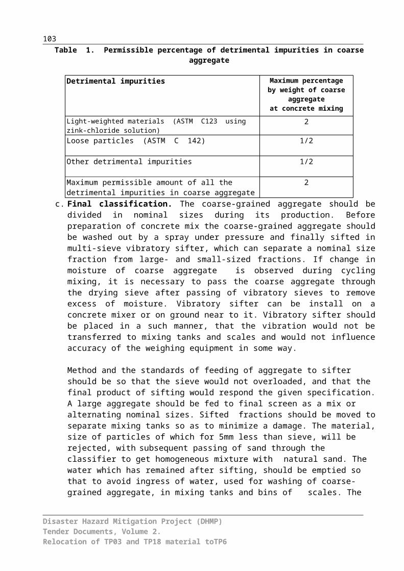
103
BILL OF QUANTITIES А. Preamble1. The Bill of Quantities (BoQ) shall be read together with Instructions to Bidders (ITB),
Conditions of Contract, Technical Specifications, and Drawings.2. The scope of works, stated in the BoQ are estimated and preliminary and constitute
the basis for tender only. The basis for payment is actual scope of contracted and implemented works, identified by the Contractor, checked by Engineer and valued according to rates and prices given in the BoQ with indicated prices, otherwise according to the rates and prices, which may be fixed by Engineer in compliance with conditions of Contract.
3. Rates and prices in the BoQ, with the exception of different envisaged within the Contract, shall include all construction plants, labor, supervision, materials, assembly, maintenance, profit, taxes (income tax, road tax, emergency tax), 20% VAT, and duties along with all general risks and commitments indicated or presumed in the Contract.
4. Rates and prices shall be presented in (Employer country currency) only, meantime the expenditures in foreign currency included in the mentioned rates and prices, shall be indicated in Section 3, Contract Data, see ITB, Item 15.
5. In the BoQ a rate and a price shall be indicated against each item irrespectively, whether scope of works is given or not. The cost of item, which was not rated or priced by the Contractor, is to be reimbursed at the expenses of other rates and prices included into BoQ.
6. A total cost corresponding to Contract provisions is to be included to the items foreseen in the BoQ with price indication. In case of lack of these items, the cost is to be distributed among other rates and prices introduced for relative types of Works.
7. No need to reiterate or summarize in the BoQ the general instructions, description of works and materials. References to corresponding sections of Contract documentation have to be done before incorporation of costs and prices against each item in BoQ.
8. An Employer is responsible for correction of arithmetical errors in compliance with Item 29 of ITB.
Daywork Works which are not included into main scop of works of the contract specifications will be implemented upon additional request of the Project Manager.
In calculating payments due to the Contractor for the execution of Daywork, the hours of labor based on a working day length in accordance with Labor Code, Kyrgyz Republic, will be counted from the time of arrival of the labor at the job site to execute the particular item of Daywork to the time of departure, but excluding meal breaks and rest periods. Only the time of categories of labor directly doing work ordered by the Project Management and for which they are competent enough to perform will be measured. The time of gangers (charge hands) actually doing work with the gangs will also be measured but not the time of foreman or other supervisory personnel.
The Contractor shall be entitled to payment in respect of the total time that labor is employed on Daywork, calculated at the all-inclusive rates entered by him in the Schedule of Daywork Rates:
Disaster Hazard Mitigation Project (DHMP)Tender Documents, Volume 2.Relocation of TP03 and TP18 material toTP6
104
The all-inclusive rates for labor shall cover all direct costs to the Contractor, including (but not limited to) the amount of wages paid to such labor, transportation time, overtime, subsistence allowances, and any sums paid to or on behalf of such labor for social benefits in accordance with Kyrgyz Republic's law, inclusive of the Contractor's profit, overheads, superintendence, liabilities, and insurance and allowances to labor, timekeeping, and clerical and office work, the use of consumable stores, water, lighting and power; the use and repair of stagings, scaffolding, workshops, and stores, portable power tools, manual plant, and tools; supervision by the Contractor's staff, foreman, and other supervisory personnel; and charges incidental to the foregoing(VAT and Social Security tax ). The basic rates will be payable in local currency only.
Daywork EquipmentThe Contractor shall be entitled to payments in respect of Equipment already on Site and employed on Daywork at the basic rental rates entered by him in the Schedule of Daywork Rates. The rates shall be deemed to include due and complete allowance for depreciation, interest, indemnity, and insurance, repairs, maintenance, supplies, fuel, lubricants, and other consumables, and all overhead, profit, and administrative costs related to the use of such equipment. The remuneration of drivers, operators, and assistants will be paid separately as described under the section on Daywork Labor.
In calculating the payment due to the Contractor for Equipment employed on Daywork, only the actual number of working hours will be eligible for payment, except that where applicable and agreed with the Project Management, the travelling time from the Site where the Equipment was located when ordered by the Project Management to be employed on Daywork and the time for return journey thereto shall be included for payment.
The basic rental rates for Equipment employed on Daywork shall be made in local currency only.The rates to be entered by the Bidder against each basic Daywork item and unit price shall include the Contractor's profit, overheads, supervision and all other charges. (VAT and Social Security tax).
The following abbreviations are used in the Bill of Quantities:
m meter sq squarepiece by number kg weight in kilogramskm kilometre no. numbermm millimetre cu cubicD diameter h hoursNo. number
B. Outline In addition to the above instructions the method of measurement shall generally be as
described in the relevant Unit Price Definitions and Specifications.
Upon coordination with the Project Manager In accordance with Section 6, Specifications
Disaster Hazard Mitigation Project (DHMP)Tender Documents, Volume 2.Relocation of TP03 and TP18 material toTP6

105
- Gravel-pebble bedding materials delivered deposits of Kulmen Sai and Mailuu Suu riverbed.
- Coble-pebble materials for gabion mattresses filling are delivered from Kulmen Sai and Mailuu Suu riverbed;
- Rock - is used form Kulmen Sai and Karagach riverbed.-All costs for transportation of materials, equipment, labor, disposal of excavated materials, and hauling, loading, unloading and handling of the same are inclusive of the unit price in the Bill of Quantities. No separate payment shall be payable to the contractor due to the change of the sources for any material because of shortages, quality or the like. The contractor shall bear all costs and expenditures for supplying and transportation including handling of the all materials at site
Disaster Hazard Mitigation Project (DHMP)Tender Documents, Volume 2.Relocation of TP03 and TP18 material toTP6

106
С. Working ItemsSummary Bill of Quantities
BOQ include following summary sheets and schedules:
Summary Sheet No. 1 – General items
Summary Sheet No. 2 – Diversion flow
Summary Sheet No. 3 – Excavation of TP3 and TP18
Summary Sheet No. 4 – Road construction works
Summary Sheet No. 5 - Disposal on TP 6
Summary Sheet No. 6 – Water treatment
Summary Sheet No. 7 - Deactivation Point
Summary Sheet No. 8 – Reconstruction of Metal Bridge
Disaster Hazard Mitigation Project (DHMP)Tender Documents, Volume 2.Relocation of TP03 and TP18 material toTP6

107
SUMMARY BOQ
Item Description Value
Relocation of TP03 and TP18 material toTP6
Summary sheet No. 1 General ProvisionsSummary sheet No. 2 Diversion flow
Summary sheet No. 3 Excavation of TP 3 and TP 18
Summary sheet No. 4 Road construction works
Summary sheet No. 5 Disposal on TP 6
Summary sheet No. 6 Water treatment
Summary sheet No. 7 Deactivation points
Summary sheet No. 8 Reconstruction of Metal Bridge
Summary amount by summary sheetsAdd 10% from Summary amount by summary sheets as Contingency Including 20 % VATBid Price (to be shifted to Bid Form)
Disaster Hazard Mitigation Project (DHMP)Tender Documents, Volume 2.Relocation of TP03 and TP18 material toTP6

108
Relocation of TP03 and TP18 material toTP6
Cost Estimate No. 1:
General Provisions
No. Description Unit Quantity
Unit rate Value
101 Bank Guarantee for Contract Implementation and for advance payment
non-recurrent
1
102 Works Insurance non-recurrent
1
103 Insurance of construction equipment non-recurrent
1
104 Insurance of responsibility to third party non-recurrent
1
1.1 Site arrangements – short-term works non-recurrent
1
1.2Construction of access roads and maintenance to the site. Payment will be done at cost.
non-recurrent
1
1.4Construction of access roads to open-pits and dumps and maintenance. Payment will be done at cost.
non-recurrent
1
1.5 Exterior lighting non-recurrent
1
1.6
Field office (incl. canteen, shower container for 2 showers, I wc pan. The construction company has to provide workers with sufficient drinking water. Fresh water shall be supplied in bottles), storehouses, production zones, including preparation of area, road, fence, water supply, sewage, electricity, drainage, and other works and maintenance.
non-recurrent
1
1.7Mobilization of all machinery, equipment, transport means and etc. required for work implementation.
non-recurrent
1
1.8 Engineering works non-recurrent
1
1.9 Implementation of radiometric survey upon completion of remediation works and relevant measures of external gamma dose rate and radioactive dust exposure which will be basis to calculate effective dose to workers during period of relocation of TP3 and TP18 onto TP6.
non-recurrent
1.10 Radiation protection during remediation works:
- Execution of Monitoring and RP Plan
- Measures to mitigate occurrence and distribution of dust during all earth
non-recurrent
Disaster Hazard Mitigation Project (DHMP)Tender Documents, Volume 2.Relocation of TP03 and TP18 material toTP6

109
works related to tailings material.
- Watering of all transportation routes is required
- Moisturized tailings mass to be relocated, transported, and deposited
- Covering of load (body) during tailings transportation
- Cleaning (washing) of trucks after working cycle (1 time per day) and before departure to public road.
- Provision the deactivation points’ water reservoir with water
1.11 Radiation protection during remediation works:
- Individual radiation protection means
non-recurrent
1.12 Implementation of QA/QC program during remediation works
non-recurrent
SHEET 1 TOTAL(to be copied to Summary Sheet)
Disaster Hazard Mitigation Project (DHMP)Tender Documents, Volume 2.Relocation of TP03 and TP18 material toTP6

Relocation of TP03 and TP18 material toTP6
Cost Estimate No. 2
Diversion flow
Item Description Unit QuantityUnit cost
(Som)
Total cost
(Som)
Total cost
(USD)
Р6 Site preparation m³ 400Р7 Soil excavation (VI group) with
excavatorm³ 200
Р8 Dig around of blocks with excavator with loading to trucks and movement to 0.5 km distance to dump
m³ 10
Р9 Blast hole charge soil crushing m³ 25Р10 Manual soil excavation in trench
for water diversionm³ 15
Total: Incl VAT-20%

Relocation of TP03 and TP18 material toTP6
Cost Estimate No.3
Excavation of TP 3 and TP 18
Item Description Unit QuantityUnit cost
(Som)
Total cost
(Som)
Total cost
(USD)
P18
Construction of construction roads to get access on TP 3 and relocation of the construction roads at the end of the construction works
m 400
Rate Purchase of geotextile to the construction site m² 1,800
P 11Placement of geotextile (GRK 4) on the prepared subgrade of the construction road
m² 1,800
P19
Excavation of materials from TP 3 including loading on trucks on the site including all works needed to be carried out in advance of and accompanying the excavation works.
m³ 110,000
P22
Excavation of materials from TP 3 applying alternative technology for excavation including loading on trucks on the site including all works needed to be carried out in advance of and accompanying the excavation works.
m³ 20,000
RateAllowance for crushing of concrete (20… 30 cm thickness of layer) to pices (30x30x30cm)
m³ 1,250
P5 option: Supply of soil (sand-gravel mixture) to the site m³ 10,000
P19Excavation of soils (sand-gravel mixture) supplied to the site m³ 10,000
P20Transport of excavated materials from TP 3 to the new depository on TP 6
m³ 110,000
P 23alternative transport technologyTransport of pulpy tailings in watertight lockable containers
m³ 20,000
P20 option: Transport of soils supplied to TP 3 after excavation m³ 10,000
P1Excavation of tailings from TP 18 including 0.5 m thick layer of the subsoil
m³ 5,000

P20 Transport of tailings from TP 18 to the new depository on TP 6 m³ 5,000
P21Construction of concrete outlet for diverting surface runoff from the final surface of TP 3
m 30
Total Incl VAT-20%
Relocation of TP03 and TP18 material toTP6Cost Estimate No. 4
Road construction works

Item Description Unit QuantityUnit cost
(Som)
Total cost
(Som)Total cost
(USD)
Item 1 Transportation route from TP3 and TP18 to TP6
Р1.1Excavation of rock soil with preliminary loosening by excavator 0.65 m³ with loading to trucks
m³ 300
Р1Soil excavation (VI group) with excavator 0.65 m² with loading to trucks
m³ 700
rate Transportation of soils by trucks up to 2.5 km distance m³ 1,000
Р2Construction of compacted embankment with dozer by 0.5 m layer with compaction
m³ 1,000
Р3 Shaping the slopes of dam with excavator m² 3,500
Р1Macadam excavation into open pit with excavator 0.65m³ with loading to trucks
m³ 5,500
rate Transportation of macadam up to 10 km distance m³ 5,500
Р4 Placement of macadam cover with 0.3-0.5m thickness m³ 5,500
Subtotal
item 2 Access technological road to TP6
Р1.1Excavation of rock soil with preliminary loosening by excavator 0.65m³ with loading to trucks
m³ 150
Р1Soil excavation (VI group) with excavator 0.65 m² with loading to trucks
m³ 170
rate
Transportation of waste soil within TP6 area with trucks up to 300 m distance
m³ 320
Р2Construction of compacted embankment with dozer by 0.5 m layer with compaction
m³ 320
Item Description Unit QuantityUnit cost
(Som)
Total cost
(Som)Total cost
(USD)
Rate Purchase of geotextile to the construction site m² 2,400
P11Placement of geotextile (GRK 4) on the prepared sub grade of the construction road
m² 2,400
Р3 Shaping the slopes of dam with excavator m² 300
Р1Macadam excavation into open pit with excavator 0.65m³ with loading to trucks
m³ 980
rateTransportation of macadam up to 10 km distance m³ 980
Р4 Placement of macadam cover with 0.3-0.5m thickness m³ 980
Subtotal
Total
Incl VAT-20%
Relocation of TP03 and TP18 material toTP6
Cost Estimate No.5Disposal of waste on TP 6
Item Description Unit Quantity Unit cost (Som)
Total cost (Som)
Total cost
(USD)
1 2 3 4 5 6 7
Item 1 TP6 – construction of disposal place at TP6
Р2 Construction of compacted embankment m³ 135,000
P24Allowance for construction of embankment from pulpy tailings material (thickness 50 cm)
m³ 20,000
Р3 Shaping the slopes of embankment by dozer m² 2,200
Rate
Disassembly of reinforced concrete with pre-loosening and its utilization
drainage system reinforced concrete pipe d
1500 mm
m³ 100
Rate Grouting of reinforced concrete pipe d=1500 mm with concrete m 90
Р13 Construction of embankment m³ 555
Subtotal
Item 2 TP6 – construction of intermediate protection cover in winter break
Р1Excavation of cover material into open-pit by excavator 0.65m³ with loading to trucks
m³ 5,500
Rate Transportation of cover material within site area up to 300 m distance
m³ 5,500
Р2.3Construction of compacted embankment by sheep-foot roller, t = 0.5 m
m³ 5,500
1 2 3 4 5 6 7

Rate Increase for construction of compacted embankment, t = 0.5 m with gradient 1:1.5
m³ 1,100
Rate
Removal of cover material by bulldozer (t = 0.4 m), leaving 10 cm of cover, transportation up to 300 m within site area, construction of compacted embankment
m³ 4,400
Subtotal
Item 3 TP6 – construction of final protection SRC cover
Р1Excavation of SRC material into open-pit by excavator 0.65m³ with loading to trucks
m³ 54,700
Rate Transportation of SRC material up to 10 km distance m³ 54,700
Р2.3Construction of compacted embankment by sheepsfoot roller, t = 0.5 m
m³ 15,000
Р2 Construction of compacted embankment m³ 39,700
RateAllowance for construction of compacted embankment on the dam slope inclined (V:H) 1:2,5
m³ 12,675
Р1
Excavation of gravel-pebble mixture (80/150) in open-pit by excavator 0,65m3 with loading to trucks
m³ 3,000
Rate Transportation of gravel-sand mixture up to 10 km distance m³ 3,000
Rate
Impression of gravel-pebble mixture (80/150) with thickness up to 0.2m into surface of protection cover
m² 30,000
Subtotal
Item 4 TP6 – Construction of drainage system
Р1.2 Excavation of drainage trench with excavator 0.65m³ m³ 1,290
Р2.1Construction of compacted embankment with one side with compaction by foot plate
m³ 1,290

1 2 3 4 5 6 7
Rate Gravel-pebble bedding t = 0.15m m³ 347
RateDelivery and placement of bentonite mats onto compacted foundation
m² 2,220
Р12Placement and fill up of Reno mattresses with gravel-pebble material d = 10 cm
m³ 230
Price Purchase of net m² 5,050
Rate Transportation of net t 10.1
Rate Provision and installation of manufactured reinforced concrete chains of round pipes d=1.0m
m 30
Rate Provision and installation of manufactured reinforced concrete chains of round pipes d=1.5m
m 17
Subtotal Total
Incl VAT-20 %
Item 4 TP 6 – Construction of storage pond
Р1.2 Excavation of regulating pond with excavator 0.65m³ into dump m³ 100
Р1Soil (VI group) excavation with excavator 0.65m³ with loading to trucks
m³ 1,100
Rate Soil transportation with trucks up to 500 m distance m³ 1,100
Р13 Construction of embankment m³ 1,200
Rate Gravel-sand bedding t = 0.15m m³ 90
Rate Delivery and placement of bentonite mats into regulating pond onto compacted base
m² 660
Р12Installation and fill up of Reno mattresses with gravel-pebble material d= 10 cm
m³ 66
Price Purchase of net for Reno mattresses m² 1,400
Rate Transportation of net for Reno mattresses t 2.8
1 2 3 4 5 6 7

RateMaintenance and installation of manufactured reinforced concrete chains of round pipes d=1.5 m
m 30
Subtotal Total
Incl VAT-20 %

Relocation of TP03 and TP18 material toTP6
Cost Estimate No.6Water treatment
Item Description Unit Quantity Unit cost (Som)
Total cost (Som)
Total cost
(USD)
1 2 3 4 5 6 7
rateWater treatment facilityEstablish, operate and remove compact mobile Water treatment facility inclusive operation during the construction time; inclusive supply of operating resources; protection of facility during the winter break.Capacity: 3 m³/hRegime of work: continuousThe effluent water should contain less than 0.5 mg/l Uranium
b) Process technologyFirst stage: Submerged pump for feeding the water constantly from the storage pond to the plant. Agitated receiving tank for dosing of hydrochloric acid (HCl) and ferrous chloride (FeCl3) for pH calibration. Retention time should be about 30 minutesSecond stage: Aeration for carbonate removal with minimum 90 minutes overall retention time. The process should be executed in 3 stages. An airflow of minimum 5 m³ per each m³ of water should be applied.Third stage: Precipitation stage in agitated tank with about 30 minutes retention time. The precipitation will be executed by lime milk addition for pH calibration at 8 – 8,5.Fourth stage: Addition of flocculants for sedimentation support. A dosing station for flocculants should feed to a tank with about 15 minutes retention time.Fifth stage: The solid liquid separation should be executed in two stages. First a thickening stage to increase the total solid content to 10 % and higher. The solid free overflow is considered
non-recurrent
1

the effluent. The second stage should be a filtering stage to generate a high-density sludge for disposal.The filtrate is recycled to the receiving tank
Rate
Construction pumping of water from pump sump at area of TP3 by dispensing pump (3m³/h) to water treatment facility. Establish, Operate and remove dispensing pump including operation during the construction time; including supply of operating resources; protection of facility during the winter break.Installation and provision of head pipeline of polyethylene from pump to water treatment facility with length up to 200 m
non-recurrent
1
Rate
Pumping of water from well of deactivation station at TP3 by pump (24 m³/ day-as filling of reserve space) into well at area of TP3. Establish, operate and remove of pump including operation during the construction time; including supply of operating resources; protection of facility during the winter break.Installation and provision of head pipeline of polyethylene from pump to water treatment facility with length up to 200 m
non-recurrent
1
Rate
Pumping of water from well of deactivation station at TP6 by pump (24 m³/ day-as filling of reserve space) into tank care and transportation to area of TP3 (up to 5 km) Establish, operate and remove of pump and tank car including operation during the construction time; including supply of operating resources; protection of facility during the winter break.Pouring out from tank car into well at TP3
non-recurrent
1
Rate Construction pumping of water from well at area of TP3 by dispensing pump (3m³/h) to pump sump at area of TP3. Repeated establish, Operate and remove dispensing pump including operation during the construction time; including supply of operating resources; protection of facility during the winter break.
h 1000

Installation and provision of head pipeline of polyethylene from pump to water treatment facility with length up to 200 m
Subtotal Total
Incl VAT-20%
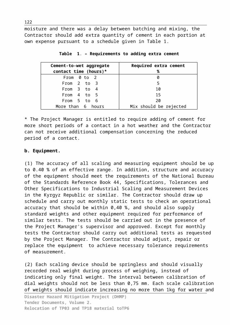
Relocation of TP03 and TP18 material toTP6
Cost Estimate No. 7
Deactivation stations (two similar stations therefore double quantity)
Item Description Unit Quantity Unit cost (Som)
Total cost (Som)
Total cost (USD)
1 2 3 4 5 6 7
Р18 Soil excavation with loading to trucks m³ 100
rateSoil transportation with trucks up to 500 m distance
m³ 100
Р16 Monolithic reinforced concrete m³ 96
Rate Reinforcement t 10
Р17 Isolation joints m 100
rate Steel grating m² 26
rate
Setup of water reservoir with capacity 5m³ equipped with hose and tap and pressure washer
unit 2
rate
Disassembly of reinforced concrete with pre-loosening and its utilization
m³ 96
Р15 Relocation of all materials to burial place m³ 100
Total
Incl VAT-20%

Relocation of TP03 and TP18 material toTP6
Cost Estimate No. 8
Reconstruction of Metal bridge
Item Description Unit Quantity Unit cost (Som)
Total cost (Som)
Total cost (USD)
1 2 3 4 5 6 7
Р25
Stripping of gravel surface of bridge and approaches, embankment behind abutments
m³ 420
Р26
Provision temporary timber deck for dismantling of steel joints with subsequent demolition
m³ 6.2
Р27
Dismantling of metal railings and joints with cutting by oxy-acetylene
t 4.39
Р27 Dismantling of in-situ r.c. backwalls m³ 7.9
Р29 Dismantling of timber cross members m 28.7
P32
Raising and lowering of steel superstructure 22.44m in length to 1m height
m 1
Bearings
Р33Cleaning of bearings surface from dirt and dust
m2 34
P34Drilling the openings d-16mm in capping beams
m 46
to a depth of 0.36m No. 128
Р35Placing of dowels into drilled openings with filling by
No 128
epoxy adhesive t 0.064
P34
Drilling the openings d-70mm in capping beams to a depth of 0.3m in location of abutment stones for
m 7.2
bearing part bolts No. 24
P37
Provision of in-situ reinforced concrete wingwalls, seismic restraints, abutment stones, Backwall and protecting walls Concrete B25
m³ 34.25
Price Purchase of reinforcement Grade I t 0.264
Price Purchase of reinforcement Grade II t 0.180
Price Purchase of reinforcement Grade III t 1.601
P39Double coat bituminous mastic waterproofing to buried concrete faces
m2 80
Superstructure
P36
Install steel bearing parts on abutment stones with fixing to base plates- tangent bearing parts– 1.53 t- base plates 0.5x0.416x0.02m– 0.191 t
No. 6
P41Sandblast cleaning of superstructure steel trusses
m2 270
P42Alignment of deformation elements of steel trusses
No. 120
P40Installation horizontal and vertical metal joints on bolts
t 3.07
P40
Strengthening lower belt of trusses using metal plate and install metal restraints with welding on upper belt of trusses
t 0.797
P43Painting of steel superstructure with provision of falseworks
t 17.87
P38
Provision of in-situ reinforced concrete superstructure slab Concrete B30
m3 17.9
Price Purchase of reinforcement Grade I t 1.404
Price Purchase of reinforcement Grade III t 3.402

P44 Installation of cast-in fittings t 0.951
P45
Installation of drainage galvanized sheet (overhang) 0.5m wide and 2 mm thickness
m2 23.3
P46Provision of overflow Concrete B20 5 cm thickness
m2 12.4
P47
Assembly of reinforced concrete kerb blocks with metal fixings Concrete B25
No. 20
P48Installation of steel welded railings with painting
t 1.3
P49Double coat epoxy resin to bridge deck surface
m2 104
P50Provision of movement joint using hot filing of "Ekspandeks" system
m 15
P39
Provision of double coat pavement using asphalt concrete mortar of 7cm thickness
m3 7.28
Bridge-to-embankment conjunction
P51 Earthworks m3 350
P52Provision of crushed stone pad under transition slabs
m3 34
P53
Assembly reinforced concrete transition slabs with its concreting Concrete B30
No. 8
Transition slabs pavement
P54
Provision of in-situ concrete blinding coat Concrete B25 on transition slabs, thickness of coat – 2cm
m2 50
P31
Provision of base for transition slabs using graded gravel mix of 24 cm thickness
m3 9
P30
Provision of double coat pavement using fine-grained asphalt concrete mortar of 7cm thickness
m3 2.52
Total
Incl VAT-20%

DESCRIPTION OF THE UNIT PRICES

List of Unit Prices for the Kyrgyz Republic
Item Description Unit price1 2 3
Р1 EXCAVATION WITH LOADING TO TRUCKSIncluded in the unit price of this item are the following:
Excavation by excavator with loading to trucks; Performance of all actions on maintenance of excavator
works; execution of manual supplementary and associated works related arrangement and maintenance of water drain or protecting roll with movement of excavator from one place to another;
Repair and maintenance of road; Activities at the tailings sites; Use of all necessary materials, tools, equipment, test
devices and workmanship; Contractor’s profit, overhead, taxes and contingencies.
m³
Р1.1 ROCK SOIL EXCAVATION WITH PRELIMINARY LOOSENING BY EXCAVATOR O.65 M³ AND LOADING TO TRUCKSIncluded in the unit price of this item are the following: Excavation with excavator to dump; Performance of all actions on maintenance of excavator
works; execution of manual supplementary and associated works related arrangement and maintenance of water drain or protecting roll with movement of excavator from one place to another;
Use of all necessary materials, tools, equipment, test devices and workmanship;
Contractor’s profit, overhead, taxes and contingencies.
m³
Р1.2 EXCAVATION OF DRAINAGE TRENCH BY EXCAVATOR 0.65M³ TO DUMP (SUBSOIL)Included in the unit price of this item are the following: Excavation with excavator to dump; Performance of all actions on maintenance of excavator
works; execution of manual supplementary and associated works related arrangement and maintenance of water drain or protecting roll with movement of excavator from one place to another;
Use of all necessary materials, tools, equipment, test devices and workmanship;
Contractor’s profit, overhead, taxes and contingencies.
m³
Р2 EMBANKMENT m³Included in the unit price of this item are the following: Leveling of soil delivered with dozer layer-by-layer of 0.3
m thickness with relocation up to 60 m; Embankment placement with dozer;
Disaster Hazard Mitigation Project (DHMP)Tender Documents, Volume 2.Relocation of TP 3 and TP 18 material to TP 6
128

Layer compaction of soil by dozer in 6 runs; Use of all necessary materials, tools, equipment, test
devices and workmanship; Contractor’s profit, overhead, taxes and contingencies.
Р2.1COMPACTED EMBANKMENT WITH COMPACTION BY RAMMING PLATEIncluded in the unit price of this item are the following:
Relocation of delivered soil by dozer to 10 m distance; Layer leveling of soil before compaction; Watering; Compaction with ramming plate suspended to boom of
excavator; Use of all necessary materials, tools, equipment, test
devices and workmanship; Contractor’s profit, overhead, taxes and contingencies.
m³
Р2.3 COMPACTED EMBANKMENT WITH COMPACTION BY SHEEP-FOOT STEAM-ROLLERIncluded in the unit price of this item are the following: Leveling of soil delivered with dozer layer-by-layer of 0.3
m thickness with relocation up to 100 m; Embankment placement with dozer; Layer compaction of soil by sheep-foot steam-roller; Use of all necessary materials, tools, equipment, test
devices and workmanship; Contractor’s profit, overhead, taxes and contingencies.
m³
Р2.4 COMPACTED EMBANKMENT WITH COMPACTION BY VIBRATION ROLLERIncluded in the unit price of this item are the following: Leveling of soil delivered with dozer layer-by-layer of 0.3
m thickness with relocation up to 100 m; Embankment placement with dozer; Layer compaction of soil by vibration roller; Use of all necessary materials, tools, equipment, test
devices and workmanship; Contractor’s profit, overhead, taxes and contingencies.
m³
P3 SHAPING THE SLOPES OF EMBANKMENT WITH EXCAVATORIncluded in the unit price of this item are the following: Shaping the slopes with soil cut and fill into dump; Use of all necessary materials, tools, equipment, test
devices and workmanship; Contractor’s profit, overhead, taxes and contingencies.
P4 MACADAM COVER OF ROADIncluded in the unit price of this item are the following: Purchase of crushed stone; Delivery of crushed stone to the place of construction; Scattering and leveling of crushed stone; Shaping and leveling of crushed stone; Rolling with watering; Use of all necessary materials, tools, equipment, test
devices and workmanship;
Disaster Hazard Mitigation Project (DHMP)Tender Documents, Volume 2.Relocation of TP 3 and TP 18 material to TP 6
129

Contractor’s profit, overhead, taxes and contingencies.
Р5GRAVEL-SAND BEDDINGIncluded in the unit price of this item are the following: Excavation of pebble-gravel in the flood plain and loading to
trucks; Hauling to distance up to 5 km; Delivery of gravel-sand material by crane to the place of
bedding arrangement; Arrangement of bedding with surface grading; Use of all necessary materials, tools, equipment, test devices
and workmanship; Contractor’s profit, overhead, taxes and contingencies.
м3
Р6CONSTRUCTION SITE PREPARATION
Included in the unit price of this item are the following: Excavation of any category ground by bulldozer,
arrangement route for machines and site cleaning; Execution of all and associated works and alignment
preparation; Use of all necessary materials, tools, equipment, test
devices and workmanship; Contractor’s profit, overhead, taxes and contingencies.
m³
Р7GROUND EXCAVATION
m³Included in the unit price of this item are the following:
Arrangement of access for excavator; Arrangement of trench, excavation of any category
ground by excavator and placing to the trench berm with compaction;
Cleaning of trench using excavator and manually with execution of all associated works;
Use of all necessary materials, tools, equipment, test devices and workmanship;
Contractor’s profit, overhead, taxes and contingencies.
Р8COARSE BLOCKS DUG USING EXCAVATOR m³
Included in the unit price of this item are the following: Excavation of any category ground by excavator and
moving to the dump during coarse blocks dug; Cleaning from stone; Execution of all associated works and alignment
preparation; Use of all necessary materials, tools, equipment, test
devices and workmanship; Contractor’s profit, overhead, taxes and contingencies.
Р9 LOOSENING BY BLAST-HOLE CHARGES m³
Included in the unit price of this item are the following: Procurement and delivery of materials for shotfiring;
Disaster Hazard Mitigation Project (DHMP)Tender Documents, Volume 2.Relocation of TP 3 and TP 18 material to TP 6
130

Pits drilling at the site of ground loosening; Preparation of explosive material, charging and tamping,
erection of explosive networks, guarding and explosion; Execution of all associated works and alignment
preparation; Use of all necessary materials, tools, equipment, test
devices and workmanship; Contractor’s profit, overhead, taxes and contingencies.
Р10MANUAL EXCAVATION
m³Included in the unit price of this item are the following:
Manual excavation of any category ground during trench arrangement and placing to the trench berm with compaction;
Cleaning of trench from stone and stone removing; Water discharge pass-by to the trench; Use of all necessary materials, tools, equipment, test
devices and workmanship; Contractor’s profit, overhead, taxes and contingencies.
Р11GEOTEXTILE PLACEMENT Included in the unit price of this item are the following:
Procurement and delivery of tools and materials requested for geotextile placement;
Preparation of foundation of geotextile and surface grading, cleaning from rubbish;
Geotextile preparation with marking and cutting up to design size;
Geotextile placement in compliance with design; Execution of all supplementary and associated works; Use of all necessary materials, tools, equipment, test
devices and workmanship; Contractor’s profit, overhead, taxes and contingencies.
m²
Disaster Hazard Mitigation Project (DHMP)Tender Documents, Volume 2.Relocation of TP 3 and TP 18 material to TP 6
131
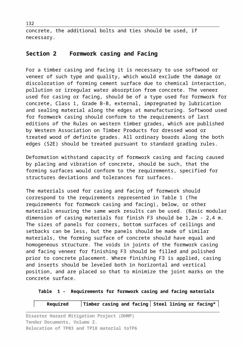
Р12GABION MATTRESSES PLACEMENT AND FILLING WITH 10-20CM OF GRAVEL-PEBBLE
m³
Included in the unit price of this item are the following: Excavation of pebble-gravel in the river bed using
excavator and loading to the dump trucks; Ground moving to the screening machine to the distance
up to of 0.1km; Screening of gravel-pebble materials up to design
fractions; Loading of gravel-pebble materials by excavator to the
dump trucks; Hauling of gravel-pebble materials to the placement area
up to of 2km distance; Mesh delivery to the placement area; Mesh placement, assembling and fixing to design
position, binding with adjacent mesh; Mesh filling with gravel-pebble manually; Top closing and fixing; Execution of all supplementary and associated works; Use of all necessary materials, tools, equipment, test
devices and workmanship; Contractor’s profit, overhead, taxes and contingencies.
Р13DAM CONSTRUCTION m³
Included in the unit price of this item are the following: Loading of soil from tailings sites to trucks; Hauling of soil by trucks to distance up to 500 m; Shaping of soil delivered by dozer with layer 0.5 m with
relocation to distance up to 20 m; Embankment placement with dozer; Layer compaction by caterpillar dozer; Execution of all supplementary and associated works; Use of all necessary materials, tools, equipment, test
devices and workmanship; Contractor’s profit, overhead, taxes and contingencies.
Disaster Hazard Mitigation Project (DHMP)Tender Documents, Volume 2.Relocation of TP 3 and TP 18 material to TP 6
132

Р14SOIL EXCAVATION BY EXCAVATOR WITH LOADING TO
TRUCKS m³Included in the unit price of this item are the following:
Loading by excavator to trucks with all works to ensure excavator’s operation, construction and maintenance of water diversion channels or fencing rolls;
Repair and maintenance of road from pit-face to the tailings sites during transportation of soil by dump trucks
Execution of all supplementary and associated works;
Use of all necessary materials, tools, equipment, test
devices and workmanship; Contractor’s profit, overhead, taxes and contingencies. Use of all necessary materials, tools, equipment, test
devices and workmanship; Contractor’s profit, overhead, taxes and contingencies.
Р15 RELOCATION OF MATERIALS TO BURIAL PLACE m³Included in the unit price of this item are the following:
Loading by excavator to trucks with all works to ensure excavator’s operation
Soil transportation by trucks to 2 km Repair and maintenance of road from pit-face to the
tailings during transportation of soil by dump trucks Execution of all supplementary and associated works; Use of all necessary materials, tools, equipment, test
devices and workmanship; Contractor’s profit, overhead, taxes and contingencies.
Р16 MASS REINFORCED CONCRETE m³ Included in the unit price of this item are the following: Purchase the mass concrete Placement of mass concrete
Maintenance of mass concrete Execution of all supplementary and associated works;
Use of all necessary materials, EG: casing (cost and transportation), tools, equipment, test devices and workmanship;
Contractor’s profit, overhead, taxes and contingencies. Р17 ISOLATION JOINTS m
Included in the unit price of this item are the following: Placement of isolation joints Execution of all supplementary and associated works;
Use of all necessary materials (their cost and transportation),
tools, equipment, test devices and workmanship; Contractor’s profit, overhead, taxes and contingencies.
Disaster Hazard Mitigation Project (DHMP)Tender Documents, Volume 2.Relocation of TP 3 and TP 18 material to TP 6
133

P18 Construction of construction roads
Construction of construction roads to get access on TP 3 and relocation of the construction roads at the end of the construction works. The width of the subgrade shall be 4.0 m. The width of the upper road surface shall be 3.5 m. The road consists of the following layers and works:
subgrade with inclination 3% perpendicular to the road axis, the subgrade shall be compacted to 97% Dpr. Acc. To Proctor test
placement of a geotextile (GRK 4 is not included under this position but can be found under Pos. P15)
placement and compaction of a 0.50 m thick layer consisting of sizing 0/70 mm in two lifts (25 cm thickness each)
placement and compaction of a 5 cm thick cover layer consisting of gravel 0/11 mm
Repair and maintenance of earth road, pavement shaping during haulage works;
Use of all necessary materials, tools, equipment, test devices and workmanship;
Contractor’s profit, overhead, taxes and contingencies.
m
P19 Excavation works on tailings pond 3
Excavation of materials from TP 3 including loading on trucks on the site including all works needed to be carried out in advance of and accompanying the excavation works. These works include:
dozing of material on the pond area to the excavation place
excavation of tailings, tailings / soil mixtures, sediment s on top of the tailings, contaminated subsoil and clean subsoil (silty sand- gravel mixtures)
crushing of concrete layer (30 cm concrete) excavation of concrete debris all surface water management measures needed
including installation and repeated removal of trenches, sumps, pumps and pipelines and pumping of the collected water to the water treatment plant
installation of groundwater wells and or piezocones to measure a potential groundwater table within the tailings body and in the quaternary underground layer
if needed, pumping of contaminated groundwater out of the tailings in order to sufficiently lower the groundwater table for further excavation works
regular maintenance of all water management installations
execution of all quality assurance / quality control measures
Performance of all actions on maintenance of excavator
m³
Disaster Hazard Mitigation Project (DHMP)Tender Documents, Volume 2.Relocation of TP 3 and TP 18 material to TP 6
134

works and dozer works; execution of manual supplementary and associated works related arrangement and maintenance of water drain or protecting roll with movement of excavator from one place to another;
Repair and maintenance of roads; Activities on the tailings pond; Use of all necessary materials, tools, equipment, test
devices and workmanship; Contractor’s profit, overhead, taxes and contingencies.
P 20 Tailings transport
Transport of excavated materials from TP 3 or TP 18 to the new depository on TP 6 including:
transport on TP 3 and on TP 18 sites and from TP 3 or TP 18 to the new waste depository on TP 6
Trucks with watertight skip moulds covered by a simple tarpaulin shall be used if moist or dry soils or tailings/soil-mixtures will be transported. If the tailings mixture seems to be too soft the ratio of dry soil vs. pulpy tailings shall be increased efore excavation.
one way traffic cycle on a ring located on both sides of the Mailuu-Suu river (total two way distance 8 km from TP 3/18 to TP 6 and back to TP3/18)
Use of all necessary materials, tools, equipment, test devices and workmanship;
Contractor’s profit, overhead, taxes and contingencies.
m³
P21 Construction of the concrete outlet trench after completion of tailings relocation works on TP 3:
installation of a concrete trench (1 m wide, 1 m deep) along the existing road for diverting the surface runoff from TP 3 site into the existing concrete trench underneath the existing road.
supply of all materials needed to the site Use of all necessary materials, tools, equipment, test
devices and workmanship; Contractor’s profit, overhead, taxes and contingencies.
m
Disaster Hazard Mitigation Project (DHMP)Tender Documents, Volume 2.Relocation of TP 3 and TP 18 material to TP 6
135

P 22 Alternative technology for excavation (long arm excavator or cable excavator) of materials from TP 3 including loading on trucks on the site including all works needed to be carried out in advance of and accompanying the excavation works. These works include:
dozing of material on the pond area to the excavation place
excavation of tailings, tailings / soil mixtures, sediment s on top of the tailings, contaminated subsoil and clean subsoil (silty sand- gravel mixtures)
crushing of concrete layer (30 cm concrete) excavation of concrete debris all surface water management measures needed
including installation and repeated removal of trenches, sumps, pumps and pipelines and pumping of the collected water to the water treatment plant
installation of groundwater wells and or piezocones to measure a potential groundwater table within the tailings body and in the quaternary underground layer
if needed, pumping of contaminated groundwater out of the tailings in order to sufficiently lower the groundwater table for further excavation works
regular maintenance of all water management installations
execution of all quality assurance / quality control measures
Performance of all actions on maintenance of excavator works and dozer works; execution of manual supplementary and associated works related arrangement and maintenance of water drain or protecting roll with movement of excavator from one place to another;
Repair and maintenance of roads; Activities on the tailings pond; Use of all necessary materials, tools, equipment, test
devices and workmanship; Contractor’s profit, overhead, taxes and contingencies.
m³
Disaster Hazard Mitigation Project (DHMP)Tender Documents, Volume 2.Relocation of TP 3 and TP 18 material to TP 6
136

P 23 Alternative transport technology:Tailings transport
Transport of excavated materials from TP 3 to the new depository on TP 6 including:
transport on TP 3 and on TP 18 sites and from TP 3 or TP 18 to the new waste depository on TP 6
Trucks with watertight lockable containers shall be used for pulpy tailings only
one way traffic cycle on a ring located on both sides of the Mailuu-Suu river (total two way distance 8 km from TP 3 to TP 6 and back to TP3)
Use of all necessary materials, tools, equipment, test devices and workmanship;
Contractor’s profit, overhead, taxes and contingencies.
m³
Disaster Hazard Mitigation Project (DHMP)Tender Documents, Volume 2.Relocation of TP 3 and TP 18 material to TP 6
137
P 24 Allowance for construction of embankment from pulpy tailings material (thickness 50 cm)
- The disposal material is a mixture of tailings and sediments from TP 03 and TP 18. Preliminary volume calculations resulted in about 130,000 m³ disposal material including about 43,000 m³ tailings. About 10,000 m³ of tailings are assumed to be of pulpy consistency.
- For the disposal on TP 6 the compacted waste material must grant a minimum undrained shear strength of 25.0 kPa.
- Dry tailings and soils shall be placed in 0.5 m thick lifts and shall be compacted by minimum 4 passes of a sheepfoot-roller.
- Mixtures of tailings and soils shall be spreaded in 0.5 m thick lifts and compacted by minimum 4 passes of a sheepfoot-roller.
- Tailings and/or soils of pulpy consistency shall be spreaded in max. 0.5 m thick lifts. Drying-out shall be used to the maximum extent possible. On each lift of pulpy material two lifts of 0.5 m thickness consisting of soil (sand-gravel mixture) shall be placed. Each lift of the upper soil shall be compacted by at least 4 passes of the dozer.
- The requirements of the QA/QC-program have to be fulfilled. Plate load tests and measurements of the natural density and dry density of the compacted layers are foreseen to prove sufficient compaction of the placed materials.
m³
Р25 Stripping of gravel surface of bridge and approaches, embankment behind abutments m3
Unit price of this item includes :
- Manual finishing in any soil group, with ejection by side-cuts to one side
of edge and throw from edge, construction and stripping of side-cuts, cleaning
of bottom and walls;
- Excavation of soil by excavator with loading to dump trucks, with performance of
all measures on excavator operation, construction and maintenance of drainage ditches
or enclosure windrows; - Haulage of soil by dump trucks for 1 km; - Highway maintenance from digging face to spoil area at soil
Disaster Hazard Mitigation Project (DHMP)Tender Documents, Volume 2.Relocation of TP 3 and TP 18 material to TP 6
138

haulage by dump truck;
- Movement and levelling of unloaded soil from dump trucks, maintenance
of areaways on spoil area, cleaning of dump truck bodies during undloading;
- Carry out all auxiliary and accompanying works; - Use all necessary materials, tools, equipment and labour force - Contractor's benefit, overheads, taxes, contingencies.
Р26 Dismantling of metal constructions of railings and joints t
Unit price of this item includes :
- Dismantling of railings and joints with cutting of metal constructions by oxy-acetylene;
- Loading and haulage of metal construcitons to 5 km;
- Carry out all auxiliary and accompanying works; - Use all necessary materials, tools, equipment and labour force; - Contractor's benefit, overheads, taxes, contingencies.
Р27 Dismantling of in-situ r/c backwalls m3
Unit price of this item includes :
- Partial dismantling by jack hammers, reinforcement cutting, removal
of dismantled walls by crane in work site with haulage to a spoil area;
- Carry out all auxiliary and accompanying works; - Use all necessary materials, tools, equipment and labour force; - Contractor's benefit, overheads, taxes, contingencies.
Р28 Construction of temporary timber deck with dismantling m3
Unit price of this item includes :
- Placing of deck with subsequent dismantling and transportation to 5km;
- Carry out all auxiliary and accompanying works; - Use all necessary materials, tools, equipment and labour force; - Contractor's benefit, overheads, taxes, contingencies.
Р29Dismantling of timber cross-bars
m3
Disaster Hazard Mitigation Project (DHMP)Tender Documents, Volume 2.Relocation of TP 3 and TP 18 material to TP 6
139

Unit price of this item includes : - Dismantling of timber structures with haulage to 5km; - Carry out all auxiliary and accompanying works; - Use all necessary materials, tools, equipment and labour force; - Contractor's benefit, overheads, taxes, contingencies.
Р30 Asphalt concrete pavement m3
Unit price of this item includes :
- Cleaning of base, placing of asphalt concrete mortar with cutting of edges, defects
removal, ramming of unrollable areas, rolling, samles cutting out and filling cutted areas;
- Liquid bitumen spreading with heating and delivery to the construction site;
- Carry out all auxiliary and accompanying works;
- Use all necessary materials (cost and haulage), tools, equipment
laboratory accessories and labour force; - Contractor's benefit, overheads, taxes, contingencies.
Р31 Gravel base on transition slabs m3
Unit price of this item includes : - Deposit and material levelling, rolling with watering; - Carry out all auxiliary and accompanying works;
- Use all necessary materials (cost and haulage), tools, equipment
laboratory accessories and labour force; - Contractor's benefit, overheads, taxes, contingencies.
Р32 Lifting and lowering of steel superstructure m
Unit price of this item includes :
- Arrangement and dismantling of suspended chute, mounting and dismantling
frames under jakking, lifting and lowering of superstructute and materials on abutments;
- Carry out all auxiliary and accompanying works;
- Use all necessary materials (cost and haulage), tools, equipment
laboratory accessories and labour force; - Contractor's benefit, overheads, taxes, contingencies.
Р33Cleaning of surface from dirt and dust
m2
Disaster Hazard Mitigation Project (DHMP)Tender Documents, Volume 2.Relocation of TP 3 and TP 18 material to TP 6
140

Unit price of this item includes : - Cleaning of surface and dust removal; - Carry out all auxiliary and accompanying works; - Use all necessary materials, tools, equipment and labour force; - Contractor's benefit, overheads, taxes, contingencies.
Р34 Drilling of openings in capping beams No.
Unit price of this item includes : - Marking of drilling places and drilling of openings; - Carry out all auxiliary and accompanying works; - Use all necessary materials, tools, equipment and labour force; - Contractor's benefit, overheads, taxes, contingencies.
Р35 Installation of dowels in ready openings with filling by epoxy adhesive t
Unit price of this item includes :
- Installation of tamplets (forms) with adjustment, fixing and demolition;
- Installation of dowels with adjustment and fixing; - Carry out all auxiliary and accompanying works;
- Use all necessary materials (cost and haulage), tools, equipment
laboratory accessories and labour force; - Contractor's benefit, overheads, taxes, contingencies.
Р36 Installation of steel bearing parts No.
Unit price of this item includes :
- Installation and attachment of anchor bolts, placing of base plates, lifting and placing of
bearing parts with fixing to base plates, arrangement of box; - Carry out all auxiliary and accompanying works;
- Use all necessary materials (cost and haulage), tools, equipment
laboratory accessories and labour force; - Contractor's benefit, overheads, taxes, contingencies.
Disaster Hazard Mitigation Project (DHMP)Tender Documents, Volume 2.Relocation of TP 3 and TP 18 material to TP 6
141

Р37, In-situ r/c bearing structures of superstructure m3
Unit price of this item includes :
- Installation and dismantling of formwork, placing of reinforcement, concrete laying
and curing, finishing of open surfaces, floating with cement of weirs;
- Carry out all auxiliary and accompanying works;
- Use all necessary materials (cost and haulage), tools, equipment
laboratory accessories and labour force; - Contractor's benefit, overheads, taxes, contingencies.
Р38 Parget waterproofing with bitument mastic m2
Unit price of this item includes :
- Cleaning and washing of insulated surface, preparation of bitumen mastics,
arrangement of waterproofing (2 layers); - Carry out all auxiliary and accompanying works;
- Use all necessary materials (cost and haulage), tools, equipment
laboratory accessories and labour force; - Contractor's benefit, overheads, taxes, contingencies.
Р39 Strengthening of trusses by sheet, arrangement of metal joints and restraints t
Unit price of this item includes :
- Mounting of metal joints on bolts, welding of sheets and restraints to trusses;
- Carry out all auxiliary and accompanying works;
- Use all necessary materials (cost and haulage), tools, equipment
laboratory accessories and labour force; - Contractor's benefit, overheads, taxes, contingencies.
Р40 Sand blasting m2
Unit price of this item includes : - Sand blast cleaning; - Carry out all auxiliary and accompanying works;
- Use all necessary materials (cost and haulage), tools, equipment
laboratory accessories and labour force; - Contractor's benefit, overheads, taxes, contingencies.
Disaster Hazard Mitigation Project (DHMP)Tender Documents, Volume 2.Relocation of TP 3 and TP 18 material to TP 6
142

Р41 Alignment of deformed elements No.
Unit price of this item includes : - Leveling of bendings and hollows on steel trusses surfaces; - Carry out all auxiliary and accompanying works; - Use all necessary materials, tools, equipment and labour force; - Contractor's benefit, overheads, taxes, contingencies.
Р42 Painting of steel superstructures with arrangement of falseworks t
Unit price of this item includes :
- Arrangement and dismantling of falseworks, cleaning of dust, rust and old painting
from elements, prime coating of surface, preparation of paint compositions, painting
of superstructures; - Carry out all auxiliary and accompanying works;
- Use all necessary materials (cost and haulage), tools, equipment
laboratory accessories and labour force; - Contractor's benefit, overheads, taxes, contingencies.
Р43 Installation of cast-in fittings into in-situ concrete t
Unit price of this item includes : - Installation and fising of cast-in fittings; - Carry out all auxiliary and accompanying works;
- Use all necessary materials (cost and haulage), tools, equipment
laboratory accessories and labour force; - Contractor's benefit, overheads, taxes, contingencies.
Р44 Placing of water-diversion galvanized sheet (overhang) m2
Unit price of this item includes : - Preparation and fixing of galvanized sheet; - Carry out all auxiliary and accompanying works;
- Use all necessary materials (cost and haulage), tools, equipment
laboratory accessories and labour force; - Contractor's benefit, overheads, taxes, contingencies.
Disaster Hazard Mitigation Project (DHMP)Tender Documents, Volume 2.Relocation of TP 3 and TP 18 material to TP 6
143

Р45 Concrete weir of 5cm thickness m2
Unit price of this item includes :
- Preparation of base course, placing and levelling of concrete layer and concrete curing;
- Carry out all auxiliary and accompanying works;
- Use all necessary materials (cost and haulage), tools, equipment
laboratory accessories and labour force; - Contractor's benefit, overheads, taxes, contingencies.
Р46 Kerb blocks No.
Unit price of this item includes : - Placing of blocks on cement mortar and finishing of joints; - Installation and welding of steel fixing elements; - Carry out all auxiliary and accompanying works;
- Use all necessary materials (cost and haulage), tools, equipment
laboratory accessories and labour force; - Contractor's benefit, overheads, taxes, contingencies.
Р47 Railings t
Unit price of this item includes :
- Preparation and arrangement of railing elements, fixing of posts, assembly of
railing elements, prime coating and painting of railings; - Carry out all auxiliary and accompanying works;
- Use all necessary materials (cost and haulage), tools, equipment
laboratory accessories and labour force; - Contractor's benefit, overheads, taxes, contingencies.
Р48 Surface treatment by 2 layers of epoxy resin m2
Unit price of this item includes :
- Washing, cutting, crack sealing and surface prime coating, preparation of
base protective coat, painting of ready surface for 2 times; - Carry out all auxiliary and accompanying works;
- Use all necessary materials (cost and haulage), tools, equipment
laboratory accessories and labour force; - Contractor's benefit, overheads, taxes, contingencies.
Disaster Hazard Mitigation Project (DHMP)Tender Documents, Volume 2.Relocation of TP 3 and TP 18 material to TP 6
144

Р49 Movement joint from hot filling of "Expandex" system m
Unit price of this item includes :
- Cleaning of construction joint surface, filling of joint by spumy sealing compound,
hot binding material, installation of needle and metal plate, clearing by hot compressed
air, laying of filling material and elastomeric-modified bitumen binding
material; - Carry out all auxiliary and accompanying works;
- Use all necessary materials (cost and haulage), tools, equipment
laboratory accessories and labour force; - Contractor's benefit, overheads, taxes, contingencies.
Р50 Earthworks for bridge-to-embankment conjunction m3
Unit price of this item includes :
- Excavation of any soil group by excavator with loading to dump-trucks with performance
of all measures on excavator operation, construction and maintenance of drainage
ditches or fence roller; - Haulage of any soil group by dump trucks for 1 km;
- Highway maintenance from digging face to spoil area at soil haulage by
dump trucks;
- Movement and levelling of unloaded soil from dump trucks, maintenance
of areaways on spoil area, cleaning of dump truck bodies during undloading;
- Compaction by air rammers and watering; - Carry out all auxiliary and accompanying works;
- Use all necessary materials (cost and haulage), tools, equipment
laboratory accessories and labour force; - Contractor's benefit, overheads, taxes, contingencies.
Р51 Crushed stone pad under transition slabs m3
Unit price of this item includes : - Placing of crushes stone layer with compaction; - Carry out all auxiliary and accompanying works;
- Use all necessary materials (cost and haulage), tools, equipment
laboratory accessories and labour force; - Contractor's benefit, overheads, taxes, contingencies.
Disaster Hazard Mitigation Project (DHMP)Tender Documents, Volume 2.Relocation of TP 3 and TP 18 material to TP 6
145

Р52 Transition slabs No.
Unit price of this item includes :
- Soil cutting, placing of transition slabs, preparation of bitument mastic and
Arrangement of parget waterproofing;
- Installation and dismantling of formwork, placing of reinforcement, concrete laying
(making monolithic of slabs) and curing; - Carry out all auxiliary and accompanying works;
- Use all necessary materials (cost and haulage), tools, equipment
laboratory accessories and labour force; - Contractor's benefit, overheads, taxes, contingencies.
Р53 Concrete blinding coat 2cm thickness m2
Unit price of this item includes :
- Preparation of base course, placing and levelling of concrete layer and concrete curing;
- Carry out all auxiliary and accompanying works;
- Use all necessary materials (cost and haulage), tools, equipment
laboratory accessories and labour force; - Contractor's benefit, overheads, taxes, contingencies.
Note: The Unit prices of works performed by using machines, equipment and devices shall include: amortization, spare parts maintenance and over handling, interest returns, insurance, mobilization, erection and dismantling of machines used.
Disaster Hazard Mitigation Project (DHMP)Tender Documents, Volume 2.Relocation of TP 3 and TP 18 material to TP 6
146