Embed Size (px)
Citation preview

M E T R O P O L I T A N W A S H I N G T O N A I R P O R T S A U T H O R I T Y
for Ronald Reagan Washington National Airport
2014
Design Manual: DCA Vol. 2
Tenant Design Standards


Ronald Reagan Washington National Airport, DCA Vol. 2 May 2014
PREFACE
THE DESIGN MANUAL
As part of the ongoing design and construction programs at Ronald Reagan Washington National Airport and Washington Dulles International Airport, the Metropolitan Washington Airports Authority (the Authority), Office of Engineering, has developed and adopted a series of documents that describe the codes, standards, details, products, and practices to be followed by Architect/Engineers (A/Es). These documents apply to all design of construction at all facilities on property owned by the Authority. Facilities constructed or modified on the site occupied by the National Air and Space Museum located at Washington Dulles International Airport are exempt from the requirements of the Authority Design Manual.
The Design Manual has been developed to assist Architects/Engineers (A/Es) in understanding the practices and policies that must be incorporated into each project. The Design Manual contains a number of specific requirements that must be followed on all projects, as described above. These can be either Authority contracted projects, Authority direct-constructed projects, and tenant contracted projects.
APPLICABILITY OF THE DESIGN MANUAL
The requirements for design and construction incorporated into the Design Manual and Supporting Volumes are regulations approved by the Metropolitan Washington Airports Authority Board of Directors and shall be considered contract requirements for all A/Es who are performing services under contract to the Authority. Although A/Es who are under contract to tenants of the Authority may not be working under contract provisions that make compliance with these requirements mandatory, the Authority reserves the right, as Owner of all airport facilities, and land on which tenant buildings are constructed, to reject any design or work that does not comply with the requirements of the Design Manual and its supporting volumes. It is, therefore, required that all A/Es performing work that will be constructed on airport property shall perform services consistent with the Authority policies, standards, procedures, and construction requirements contained in the Design Manual and its supporting volumes. The Design Manual should be considered equivalent to the building codes. The Design Manual in effect at the 30% Submittal will remain the Design Manual of record up to the 100% Final Submittal.
ORGANIZATION OF THE DESIGN MANUAL
The Design Manual is made up of seven volumes. Basic policies, procedures and standards for both Airports:
· Design Manual Requirements for Ronald Reagan Washington National Airport:
· DCA Vol.1 - Airport Design Standards and Signing Guidelines · DCA Vol.2 - Tenant Design Standards [THIS DOCUMENT]
DCA Vol. 2 - Page 3 Preface

Ronald Reagan Washington National Airport, DCA Vol. 2 May 2014
Requirements for Washington Dulles International Airport: · IAD Vol.1 - Airport Design Standards and Signing Guidelines · IAD Vol.2 - Main Terminal/Concourse Z Tenant Design Standards · IAD Vol.3 - Concourse B Tenant Design Standards
Requirements for All Projects:
· CADD - CADD Design Standards The seven volumes are intended to supplement each other and must be used together, as appropriate for each airport, to achieve the desired goals of the Authority.
An electronic version of the Design Manual and Supporting Volumes is available on CD-ROM, which may be obtained by contacting the Authority Office of Engineering. It is also available on the Authority website at www.mwaa.com under “Publications”.
OTHER DOCUMENTS
In addition to the Design Manual, the Authority also requires compliance for design and construction with additional policies, procedures, and standards that are published by other departments. These documents include:
· Construction Safety Manual · Owner Controlled Wrap-Up Insurance Program Manual
· Building Codes Manual
· Contractors Safety and Security Information (Washington Dulles International Airport)
· Safety Policy, Procedures, and Practices by the Risk Management Department
· MASTERSPEC© Specifications Sections specifically edited for Authority projects (primarily Division 01, but
including specific technical specification sections)
· Ronald Reagan Washington National Airport and Washington Dulles International Airport Survey Control Data “To-Reach” Descriptions (two separate volumes) Note that the “To-Reach” documents for Washington Dulles International Airport are no longer provided on the CD-ROM version of the Design Manual. These documents are available through the Authority. The CD-ROM contains information directing the A/Es to the proper group within the Authority to obtain this document.
DCA Vol. 2 - Page 4 Preface

Ronald Reagan Washington National Airport, DCA Vol. 2 May 2014
ACCEPTABLE STANDARDS
The standards established by the above referenced documents, together with Federal Aviation Administration (FAA), National Fire Protection Agency (NFPA), Virginia Uniform Statewide Building Code (USBC), Construction Specifications Institute (CSI), and other referenced materials establish the minimum level of quality and detail required of all Authority projects. These standards in many instances may exceed those used in non-Authority design and construction projects and are often above those established as “Code Minimums”, “Standards of the Industry”, or “generally accepted practices.”
DESIGN MANUAL REVISIONS
This edition of the Design Manual incorporates the modifications and additions that were developed during the Authority annual review of the previous year’s Design Manual. This review includes an analysis of the existing standards and an evaluation of the suggested revisions.
If you feel that a standard or procedure stipulated in this edition of the Design Manual should be revised, we would like to know. To facilitate this, we have included a Design Manual review form that will place your idea in the appropriate hands. All suggestions received will be reviewed and researched and a written response will be provided.
DCA Vol. 2 - Page 5 Preface

Ronald Reagan Washington National Airport, DCA Vol. 2 May 2014
DESIGN MANUAL REVISION FORM
SUGGESTED REVISION TO THE DESIGN MANUAL
Date: Log Number: 14-
To: Ms. Diane R. Hirsch, PE Manager of Design Metropolitan Washington Airports Authority Ronald Reagan Washington National Airport Washington, DC 20001
From:
Design Manual Volume & Section:
Design Manual Paragraph:
Design Manual Page:
Background: [Insert background for suggested change(s) here.] 2014 Design Manual Text: [Copy and paste here the text from the 2014 Design Manual for which a revision will be suggested.] Proposed 2015 Design Manual Text: [Use RED text, normal font not bold, to indicate added language. Use “strikethrough” to indicate deleted language. Do not use “track changes”.]
DCA Vol. 2 - Page 6 Preface

Ronald Reagan Washington National Airport, DCA Vol. 2 May 2014
TABLE OF CONTENTS
PREFACE ................................................................................................................................................................................. 3
TABLE OF CONTENTS ............................................................................................................................................................ 7
INTRODUCTION ..................................................................................................................................................................... 11
SECTION III: Tenant Design Standards .............................................................................................................................. 13
CHAPTER 1 General .............................................................................................................................................................. 13
1.1 Introduction ........................................................................................................................................................ 13
1.2 Applicability ....................................................................................................................................................... 17
1.3 Family of Design Related Documents ............................................................................................................. 17
1.4 Commercial Programs ...................................................................................................................................... 18
1.5 Architectural Enhancement Program (AEP) ................................................................................................... 19
1.6 General Building Shell Spaces ......................................................................................................................... 22
1.7 ADA Compliance ............................................................................................................................................... 27
1.8 Indoor Environmental Quality .......................................................................................................................... 28
CHAPTER 2 AIRLINE SHELL SPACES ................................................................................................................................ 31
2.1 All Space Types ................................................................................................................................................. 31
2.2 Offices, ATOs, Clubs (Baggage Claim, Concourse, Ticketing and Club Levels Terminal B/C) ................. 33
2.3 Airline Operations – Terminal B/C And Connector ........................................................................................ 34
2.4 Airline Casework ............................................................................................................................................... 35
CHAPTER 3 Retail Shell Spaces .......................................................................................................................................... 39
3.1 Concourse/Piers/Bag Claim ............................................................................................................................. 39
DCA Vol. 2 - Page 7 Table of Contents

Ronald Reagan Washington National Airport, DCA Vol. 2 May 2014
3.2 Retail Storefronts – Connector......................................................................................................................... 43
3.3 Retail Kiosks ...................................................................................................................................................... 43
3.4 Retail Support Spaces ...................................................................................................................................... 45
3.5 Vacated Spaces ................................................................................................................................................. 45
CHAPTER 4 Food-and-Beverage Shell Spaces .................................................................................................................. 49
4.1 North/South Concourse/Piers .......................................................................................................................... 49
4.2 Connector ........................................................................................................................................................... 52
4.3 Public Square Kiosks ........................................................................................................................................ 53
4.4 Ticket Level Café ............................................................................................................................................... 58
4.5 Destination Restaurant ..................................................................................................................................... 63
4.6 Food And Beverage Support Spaces .............................................................................................................. 66
4.7 Vacated Spaces ................................................................................................................................................. 67
CHAPTER 5 General Design Standards .............................................................................................................................. 71
5.1 Applicability ....................................................................................................................................................... 71
5.2 General Criteria/Prohibitions ............................................................................................................................ 71
5.3 Enforcement ....................................................................................................................................................... 93
CHAPTER 6 Airline Tenant Design Standards ................................................................................................................... 97
6.1 Locations Governed By Tenant Design Standards ........................................................................................ 97
6.2 General Criteria/Prohibitions ............................................................................................................................ 97
6.3 Curbside Check-In ............................................................................................................................................. 98
6.4 Airline Ticket Counters And Backwalls ......................................................................................................... 105
6.5 Shuttle Ticket Counters And Backwalls ........................................................................................................ 114
DCA Vol. 2 - Page 8 Table of Contents

Ronald Reagan Washington National Airport, DCA Vol. 2 May 2014
6.6 Bridge Check-In ............................................................................................................................................... 118
6.7 Clubs ................................................................................................................................................................. 118
6.8 Baggage Service Offices ................................................................................................................................ 127
6.9 Apron Operations Areas ................................................................................................................................. 141
6.10 Hold Rooms ................................................................................................................................................... 145
6.11 Baggage Claim Lobby ................................................................................................................................... 148
6.12 Other Airline Equipment/Fixtures ................................................................................................................ 148
CHAPTER 7 Retail Tenant Design Standards ................................................................................................................... 161
7.1 Locations Governed By Standards ................................................................................................................ 161
7.2 General Criteria/Prohibitions .......................................................................................................................... 161
7.3 North/South Concourse Storefronts .............................................................................................................. 162
7.4 Pier Storefronts ............................................................................................................................................... 162
7.5 Connector Storefronts .................................................................................................................................... 162
7.6 Kiosks ............................................................................................................................................................... 163
7.7 Retail Merchandising Units (RMU) ................................................................................................................. 166
CHAPTER 8 Food-and-Beverage Tenant Design Standards ........................................................................................... 169
8.1 Locations Governed By Standards ................................................................................................................ 169
8.2 General Criteria/Prohibitions .......................................................................................................................... 169
8.3 North/South Concourse Storefronts .............................................................................................................. 171
8.4 Pier Storefronts ............................................................................................................................................... 172
8.5 Connector Storefronts .................................................................................................................................... 172
8.6 Public Square Kiosks ...................................................................................................................................... 173
DCA Vol. 2 - Page 9 Table of Contents

Ronald Reagan Washington National Airport, DCA Vol. 2 May 2014
8.7 Ticket Level Café ............................................................................................................................................. 179
8.8 Destination Restaurant ................................................................................................................................... 183
8.9 Bridgewell Café ................................................................................................................................................ 185
8.10 Concourse Restaurant Seating .................................................................................................................... 186
8.11 Prohibitions .................................................................................................................................................... 186
CHAPTER 9 Advertising Tenant Design Standards ......................................................................................................... 189
9.1 Locations Governed By Standards ................................................................................................................ 189
9.2 Advertising Shell Space .................................................................................................................................. 189
9.3 Metering ............................................................................................................................................................ 194
9.4 General Criteria/Prohibitions .......................................................................................................................... 194
CHAPTER 10 Miscellaneous Commercial Standards ...................................................................................................... 197
10.1 Applicability General: .................................................................................................................................... 197
10.2 General Criteria/Prohibitions ........................................................................................................................ 210
LIST OF EXHIBITS ............................................................................................................................................................... 213
INDEX ................................................................................................................................................................................... 217
DCA Vol. 2 - Page 10 Table of Contents

Ronald Reagan Washington National Airport, DCA Vol. 2 May 2014
INTRODUCTION
GUIDE TO THIS VOLUME OF THE DESIGN MANUAL
Ronald Reagan Washington National Airport consists of the following sections:
· DCA Vol. 1 - Airport Design Standards and Signing Guidelines
· DCA Vol. 2 - Tenant Design Standards [THIS VOLUME]
This volume consists of design standards, design criteria, procedures, and products for Ronald Reagan Washington National Airport and relates to the Tenant Design Standards.
This volume consists of one section::
Section III Tenant Design Standards Chapter 1: General Chapter 2 Airline Shell Spaces Chapter 3 Rental Shell Spaces Chapter 4 Food-and-Beverage Shell Spaces Chapter 5 General Design Standards Chapter 6 Airline Tenant Design Standards Chapter 7 Retail Tenant Design Standards Chapter 8 Food-and-Beverage Tenant
Design Standards Chapter 9 Advertising Tenant Design
Standards Chapter 10 Miscellaneous Commercial
Standards
DCA Vol. 2 - Page 11 Introduction

Ronald Reagan Washington National Airport, DCA Vol. 2 May 2014
(This Page Blank)
Tenant Design Standards DCA Vol. 2 - Page 12 Section III

Ronald Reagan Washington National Airport, DCA Vol. 2 May 2014
SECTION III: Tenant Design Standards
CHAPTER 1 General
All construction in or around Terminal B/C, from first time fit-out of tenant or Authority occupied areas and all subsequent revisions, shall be completed within the context of the original design intent. The design intent extends from architectural and structural expression through the design of all supporting systems and interior or exterior finishes, furnishings, and fixtures. All tenants and Authority Departments are advised that all projects, of any size, undertaken within the Terminal B/C area which temporarily or permanently alters the Terminal in any manner will comply with all standards set forth and will be reviewed for adherence to such standards prior to approval of any work to construct or otherwise implement the projects. All tenant and Authority improvements or modifications, as required to meet operational or program requirements or changes to operations and programs requirements due to changes in tenancy, shall be strictly controlled. Such improvements and alterations shall be executed to maintain the design intent set forth in the Design Manual and this volume of the Design Manual.
1.1 Introduction
1.1.1 General: The purpose of this section is to provide prospective tenants with information to acquaint them with the aesthetic requirements established for Terminal B/C with respect to the design of tenant leased areas. The information contained herein should be shared with the tenant design professionals, as they will be required to comply with the stated design criteria. The design of all individually occupied facilities shall be compatible with the architectural design characteristics of the overall terminal complex. Major aesthetic issues, such as the visual appearance of tenant-exclusive or common-use areas, use of materials, colors, lighting, and signage will be addressed by this section to ensure that the design of such facilities is supportive of the architectural elements and their composition in the publicly experienced or viewed spaces in the Terminal. Initial development of Tenant spaces and the
maintenance of those spaces throughout the life of the tenancy shall promote, rather than detract from, the efficient, service-oriented, functional aspects of the Terminal by encouraging wayfinding, ease of circulation, and enhancing the passenger and visitor traveling experiences. Tenants are encouraged to review any individual design concerns arising from use of these standards with the Authority prior to and throughout the design process to ensure that their final design meets with the approval of the Authority.
1.1.2 General Building Description: The Ronald Reagan Washington National Airport Terminal Complex consists of three interconnected terminal facilities. The terminals are designated alphabetically from south to north; beginning with the first terminal an airport patron would approach on the airport roadway network. Exhibit III-1-1 illustrates the relationship of the three terminal areas. Terminal A (also known as the “Main Terminal”), the first facility on the roadways, consists of the original 1941 Terminal and subsequent additions. This terminal consists of approximately 350,000 sq. ft. on four levels with nine aircraft gates and is discussed in detail in Section I. Terminal B/C is an approximately 1 million sq. ft. passenger facility on four levels, linked to Terminal A by a pedestrian walkway. The uppermost level, location of the airline ticket counters, is served by an elevated roadway for departing passenger drop-off. The middle level comprises the main North/South Concourse; three piers served by 31 gates; and the Connector to Terminal A, which is served by four gates. Pedestrian bridges to the Metro and parking garages are also at this level. Passenger arrivals and Baggage Claim are on the Ground Level. Service and FAA administrative functions are located on the lowest (sub - level). Terminal B/Cs primary architectural features include a repetitive structural steel bay with open framed domes and vaulted spaces.
Tenant Design Standards DCA Vol. 2 - Page 13 Section III

Ronald Reagan Washington National Airport, DCA Vol. 2 May 2014
Terminal Designations Exhibit III-1-1
Tenant Design Standards DCA Vol. 2 - Page 14 Section III

Ronald Reagan Washington National Airport, DCA Vol. 2 May 2014
The proportions provide a civic image appropriate both to the urban gateway to the nation’s capital and the context established by historic Terminal A. The Terminal B/C cross-section maximizes public views to the site. The site consists of the airfield and the Potomac River in the foreground with the Federal Core in the background. The internal vistas between the Ticketing Level and Concourse Level, along the length of the terminal, enhance passenger and visitor wayfinding in the primary public spaces.
1.1.3 Materials: The following description of exterior and interior materials and treatments is provided as context for the benefit of the tenant planning and design professionals responsible for preparing design documents in support of tenant construction within Terminal B/C.
1.1.3.1 The North/South Concourse Exterior: The exterior cladding consists of clear, patterned and spandrel glass with a painted aluminum mullion system with a 2' – 0" vertical and 8' – 0" horizontal module. The curtain wall system includes painted metal panels and louvers on the public arrivals curb and at the lower apron level. The public entry doors are stainless steel. All service doors are painted metal with stainless steel scuff guards, refer to Paragraph 1.1.3 for additional information.
1.1.3.2 Pier Exteriors Including the Connector: The exterior cladding consists of clear, patterned glass with a painted aluminum mullion system and painted metal panels. The lower apron level of the Connector is concrete with painted metal louvers and doors. The lower apron level of the Piers will be painted metal panels.
1.1.3.3 Metro Bridge Exterior: The exterior cladding consists of clear, patterned glass with a painted aluminum mullion system and painted metal panels.
1.1.3.4 North/South Concourse Interior: The interior public spaces feature exposed painted steel columns, roof domes, roof vaults, and trusses. The roof domes and vaulted ceilings consist of painted structural members, infilled with perforated metal acoustical panels, and have
skylight oculi that are glazed with non-glare glass. Floors in public circulation areas consist of a four colored, patterned terrazzo with stainless steel bases, and aluminum divider strips. All non-glass wall surfaces are a combination of drywall, painted metal panels, and high impact wall panels, refer to Paragraph 1.1.3 for additional information. Ceramic tile is used in the restrooms. Balustrades are perforated stainless steel panels.
1.1.3.5 Connector and Pier Interiors: The interior public ceiling in the Connector is coffered drywall, acoustical tile, and perforated painted metal panels. The Connector floors consist of restored original terrazzo and terrazzo compatible in color and pattern to that which exists in Terminal A. Interior walls and columns have cast stainless steel perimeter bases. All non-glass wall surfaces are a combination of drywall, high impact wall panels, and painted metal with a mixture of existing and new blue-green wall tile. Balustrades on the moving sidewalk are glass, trimmed out in stainless steel. The interior public ceiling in the piers is acoustical tile and drywall. The floors in public circulation areas are terrazzo tile, the hold rooms carpeted. All interior walls and columns will have stainless steel bases. All non-glass walls will be a combination of drywall, high impact wall panels, and painted metal.
1.1.3.6 Metro Bridge Interiors: The interior ceiling consists of custom aluminum panels, both curvilinear and flat. Floors are terrazzo tile. Moving sidewalks occur on either side of the public circulation corridor. Non-glazed wall surfaces occur where the Bridges intersect the Terminal and the Farecard Plazas.
1.1.4 Colors: A palette of colors has been established for Terminal B/C. Detailed information about colors and materials is contained in the Architectural Color and Finish Submittal Volumes 1 and 2 that are available through the Authority. A brief summary of colors and their use on exterior and interior surfaces follows on the next page.
Tenant Design Standards DCA Vol. 2 - Page 15 Section III

Ronald Reagan Washington National Airport, DCA Vol. 2 May 2014
EXTERIOR
Element Color/Pattern
Exterior Curtain Wall “Washington White” PPG # UC 70129 BC
Exposed Structural Steel Creamy Yellow Custom Color Sample
Underside of Roadway Bright Galvanized Steel
Roof
Stainless Steel /Hypalon Membrane
Medium Gray
Roadway and Curb Signs DCA Standard Dark Gray Custom Color Sample
Terminal B Sign Field Red Munsell 7.5R3/10
Terminal C Sign Field Blue Munsell 5B 3/8
INTERIOR
Element Color/Pattern
Glazing
Clear Vision Glass Clear Vision Glass with white frit pattern
Horizontal lines 20° to 70° coverage range
Metal Panels – Wall Metal Panels - Ceiling
Warm White Warm White
Matches High Impact Wall Panels Benjamin Moore #967
High Impact Wall Panels
Vinyl Wrapped Wall Panel - Warm White
Horizontal line /Texture
Exposed Structural Steel Creamy Yellow Custom Color Sample
Mullions “Washington White” PPG # UC 70129 BC
Metal/Spandrel Panels White Custom Color Sample
Terrazzo Floor -Border Warm Gray Custom Color Sample
Terrazzo Floor – Field Black Custom Color Sample
Terrazzo Floor – Accents Red and Creamy Yellow Custom Color Sample
Tenant Design Standards DCA Vol. 2 - Page 16 Section III

Ronald Reagan Washington National Airport, DCA Vol. 2 May 2014
Element Color/Pattern
Carpet
Custom Color Warm Gray with Black, Rust, Red Accents
Linear Pattern Grid Series SW 221716
Casework Elements Stainless Steel Flat Sheet, Corrugated, Perforated and Checker Pattern with No. 4 Polish Finish
Elevators Stainless Steel No. 4 Polish Finish
Guard Rail Panels Stainless Steel Perforated with No. 4 Polish Finish
Guard Rail Stanchions Painted Steel-Warm White Benjamin Moore #967
Wayfinding Signs Dark Burgundy/White/ Stainless Steel Frames
Munsell 7.5R 3/2
Terminal B Sign Field Red Munsell 7.5R 3/10
Terminal C Sign Field Blue Munsell 5B 3/8
1.2 Applicability
1.2.1 General The design standards contained in this section are applicable to a variety of tenants and facilities within Terminal B/C and the Connector. Some facilities may be provided fully completed or turnkey, there may be specific elements within spaces that are made available to tenants, and tenants may have to comply with criteria applied to specific zones in their facilities. In any case, these standards are applicable to tenants or occupants as outlined below:
1.2.3 Lease tenants who will design and construct new spaces in Terminal B/C Building, or Connector to Authority specified criteria or standards
1.2.4 Lease tenants who will design and construct alterations to existing spaces in Terminal B/C or Connector to Authority specified criteria or standards.
1.2.5 Lease tenants who will occupy spaces or facilities in Terminal B/C or Connector, all of which have been constructed or otherwise provided by the Authority.
1.2.6 Lease tenants who will occupy spaces or facilities in Terminal B/C or Connector, portions or elements of which have been provided or constructed by the Authority.
1.2.7 Authority employees or other agents thereof, who will occupy spaces constructed or otherwise provided by the Authority.
1.3 Family of Design Related Documents
1.3.1 General: The Metropolitan Washington Airports Authority has developed a family of documents which describes procedures, codes, standards, details, and practices to be followed in the design and construction of any and all facilities on the Airport. All tenant design and construction will be in accordance with the requirements of the latest edition of these documents. Each document is reviewed by the Authority and updated on a regular basis
Tenant Design Standards DCA Vol. 2 - Page 17 Section III

Ronald Reagan Washington National Airport, DCA Vol. 2 May 2014
as necessary. It is the responsibility of the tenant to ensure that the current edition of each document is referenced during the design and construction process. The documents and a brief description of their contents are described below. These tenant design standards are to be used in conjunction with these other documents. Where different levels of restriction are referenced, tenants will be required to follow the most restrictive requirements.
1.3.2 Design Manual: The Design Manual is a compilation of comprehensive architectural and engineering guidelines for all facilities and structures, new and existing, as well as guidelines for the development of specific land use areas on both airports controlled by the Authority, Ronald Reagan Washington National Airport and Washington Dulles International Airport. The Design Manual is a mandatory guide and has the force of law on the Airport. This document is issued by the Authority Office of Engineering and is updated annually. The Design Manual is supplemented by separate supporting volumes for each airport containing a series of standards or guidelines. The volumes for Ronald Reagan Washington National Airport consists of the following sections:
1.3.2.1 Section I: Design Standards
1.3.2.2 Section II: Signing Design Guideline
1.3.2.3 Section III: Tenant Design Standards Terminal B/C (this Section)
1.3.2.4 Section IV: Tenant Design Standards Terminal A (to be issued at a later date)
1.3.3 Tenant Work Letter: This document contains a comprehensive listing of the specific tenant requirements for each tenant contract entered into by the Authority. It contains a physical description, including dimensions, of the particular area to be used, any information with regard to the specific financial agreement reached with the tenant, and any other items which are specific to each tenant project. This document contains both standard and tenant-specific text, and therefore, is individually prepared
for each tenant lease area. This document is prepared by the Authority Concessions and Property Development Department.
1.3.4 New Terminal and Related Facilities Construction Documents: For guidance regarding existing construction documents relating to Terminal B/C and related facilities, contact the Airport Facilities Engineering Division.
1.3.5 Historic Preservation Design Guidance: Historic Preservation Design Guidance for Development of the Dining Room at Ronald Reagan Washington National Airport: The historic dining room space is located on the second floor of the North Wing of Terminal A and contains the airline club and the Authority public space. Tenants in the Connector are directed to review Section I of DCA Vol. 1 of the Design Manual for background on historic preservation issues related to this area.
1.4 Commercial Programs
1.4.1 Overview: The Authority desires to provide the users of Ronald Reagan Washington National Airport with retail and food-and-beverage facilities that match user wants and needs. It is also the Authority’s intent to provide attractive, well-designed tenant facilities. These design standards are intended to ensure that the design and execution of commercial tenant spaces occur in a manner that enhances their visibility and viability while supporting the architectural quality of the exterior and interior public spaces. The marketing of products and services in Terminal B/C will be enhanced by the use of these standards and the creation of the commercial theme: “National Hall”. This theme is reinforced through the architectural design, the application of the “National Hall” name, color, and logo, as well as through the use of signing, custom retail light fixtures, and light stanchions which are incorporated into various casework elements. Advertising opportunities to further promote marketing have also been considered by the Authority in the form of commercial directories and advertising wall and floor units.
Tenant Design Standards DCA Vol. 2 - Page 18 Section III

Ronald Reagan Washington National Airport, DCA Vol. 2 May 2014
1.4.1.1 Storefront Design: The storefront design for Terminal B/C shall follow the retail tenant submission requirement booklets for the N/S Concourse, Piers, and Connector. These requirement booklets are available through Concessions and Property Development or can be found in electronic format on the Design Manual 2006 CD. The requirements of these booklets supersede existing in place design requirements only and would take effect as existing tenant leases expire or when the tenant wishes to remodel their space. The Design Manual will take precedence over these booklets for everything except the design control zone. The booklets will become appendices in part or in total of the Design Manual for the design control zone only as noted below:
A. Retail Tenant Submission Requirements – N/S Concourse – this booklet in its entirety becomes part of the Design Manual.
B. Retail Tenant Submission Requirements – Piers and Connector - Paragraphs 1 through 20.5 on pages 21 through 33 of this booklet shall be in addition to and not a replacement of the basic requirements of the Design Manual.
1.4.2 Provisions for Flexibility: Provisions to allow opportunities for a flexible mix of retail and food-and-beverage concessions have been considered for Terminal B/C. Specific Retail areas along the North/South Concourse can accommodate either retail or food-and-beverage tenant occupants. Refer to detailed descriptions of shell space contained in Chapters 3 and 4 of this volume for specific provisions.
1.5 Architectural Enhancement Program (AEP)
1.5.1 Architectural Enhancement Program Inventory: The Architectural Enhancement Program seeks to maximize the visual richness of Terminal B/C through the integration of carefully commissioned art works with the
architectural surfaces and elements of the facility. The commissions represent multi-disciplined collaborations, including participation by the Design Architect. An inventory of the 30 artistic commissions follows and is shown diagrammatically in Exhibits III-1-2 and III-1-3.
1.5.1.1 Ten floor medallions, 18' – 0" in diameter, along the length of the Concourse Level which are fully visible from the upper Ticketing Level lobby.
1.5.1.2 Ten porcelain enamel panel installations intermediately spaced within the Ticketing Level balustrade.
1.5.1.3 One sculptural balustrade installation approximately 135' – 0" long, at the center bow of the Ticketing Level (at the Café).
1.5.1.4 One integrated trellis panel at the south exterior wall of the Ticketing Level lobby.
1.5.1.5 Two glass friezes within the east facing exterior curtainwall along the main North/South Concourse, each approximately 2' x 440'.
1.5.1.6 Four 6' x 24' murals made up of nine 2' x 8' panels on walls flanking the entries from the pedestrian bridges at the Concourse Level.
1.5.1.7 One portal piece (screen wall) located on the Concourse Level in the center wall facing the escalator to the Baggage Claim Level.
1.5.1.8 One approximately 24" x 46" painting located on the elevator wall at the concourse level opposite the center security checkpoint.
1.5.2 Prohibitions/Restrictions: No tenant design or construction shall remove, obstruct, modify, or otherwise alter any elements of the Architectural Enhancement Program.
Tenant Design Standards DCA Vol. 2 - Page 19 Section III

Ronald Reagan Washington National Airport, DCA Vol. 2 May 2014
AEP Location Plan, Concourse Level Exhibit III-1-2
Tenant Design Standards DCA Vol. 2 - Page 20 Section III

Ronald Reagan Washington National Airport, DCA Vol. 2 May 2014
AEP Location Plan, Ticket Level Exhibit III-1-3
Tenant Design Standards DCA Vol. 2 - Page 21 Section III

Ronald Reagan Washington National Airport, DCA Vol. 2 May 2014
1.6 General Building Shell Spaces
1.6.1 General: The purpose of this chapter is to define the level of expected finish and construction completion for facilities and systems that are provided by the Authority for all tenant areas. Descriptions are provided for the areas in chapters noted below.
1.0 2.0 3.0 4.0
General Building Shell Spaces Airline Shell Spaces Retail Shell Spaces Food and Beverage Shell Spaces
Tenants shall reference the provisions of the following sub-sections for overall applicability and subsections located in Chapters 2, 3 and 4 for particulars by tenant type.
1.6.2 Walls: Enclosing walls will have finished surfaces on the non-tenant side only. Demising walls between tenants will be provided by the Authority as part of the base building construction. Demising walls will terminate at the storefront façade. Tenants shall be responsible for completing their respective sides of the demising partition.
1.6.3 Storefronts: Interior façades or storefronts facing public areas will be completed by the tenant except as noted in individual chapters. For the purpose of using this document, “storefront” shall be defined as the area measuring the width of tenant frontage between demising walls and between the floor and building structure above, which provides the separation between the tenant-lease space and the public space.
1.6.4 Ceilings: There may be no finished ceiling or soffit, except as required for fire-rated floor, wall or roof assemblies, or as noted. All overhead sprinkler, electrical, plumbing, or HVAC components will permit the installation of a minimum ceiling height of 9' – 0" except as noted.
1.6.5 Doors: Where enclosing walls around tenant areas are provided, hollow metal doors and frames are also provided. Where required, door assemblies are fire-rated
and labeled in order to comply with all criteria for the fire rating. Doors and door frames have a painted finish on both surfaces.
1.6.6 Floor and Roof Structure: Floor slabs are provided by the Authority. Because of the relatively poor soil conditions typical of the Potomac shore, slabs at grade are structurally reinforced concrete. The Concourse and Ticketing Level floors are framed with wide flange steel beams and girder sections. These act composite with a lightweight concrete slab on top of a metal deck. Similar framing is provided on the three Piers. Similar framing, with varying depth, occurs at the Connector. Structural bays vary at the Connector as this two-story structure dovetails with the structure of Terminal A. Except as noted in individual chapters, no finished flooring is provided. Floor structure has been designed to support 100 lbs. per sq. ft. An allowance of 10 lbs/sf is provided in the design of floor and roof systems in anticipation of tenant provided and installed HVAC equipment and/or systems that may be suspended from the Terminal structure. Refer to Chapter 5 of this volume for general design criteria.
1.6.7 Telecommunications and Special Systems
1.6.7.1 Telecommunications: Terminal B/C is provided with dual feeds for telecommunications. Feeds from each manhole into the Main Telecommunications Facility (MTF) will consist of eight 4" conduits. Distribution from the MTF to remote telecommunications rooms is via a dedicated conduit. The MTF and remote telecommunication rooms are provided with uninterruptible power service (UPS). The Authority will provide a Premise Distribution System (PDS) to interconnect the MTF with remote telecommunications rooms and closets. The PDS backbone cabling will consist of multi-pair copper cable for voice and fiber optic cable for higher speed data or other special applications. The Authority will provide each tenant space with an interface to the PDS backbone. Both multi-pair copper and fiber optic cable will be terminated on a demarcation panel in each tenant exclusive-use space. Conduit, cable, and termination hardware to the demarcation panel will be provided by the Authority. Conduit, cable, and termination hardware to this
Tenant Design Standards DCA Vol. 2 - Page 22 Section III

Ronald Reagan Washington National Airport, DCA Vol. 2 May 2014
demarcation point will be provided. Each tenant shall be responsible for cabling their own lease areas and providing the necessary cross-connects to the Premise Distribution System. Cabling shall comply with EIA/TIA 568 specifications. Tenants may elect to utilize Unshielded Twisted Pair (UTP) and/or Shielded Twisted Pair (STP). Procurement and installation of such cable within tenant exclusive-use spaces shall be the responsibility of the tenant.
1.6.7.2 Master Clock System: The Authority will provide a Master Clock system with time displays installed in the directories located throughout the terminal. Should tenants require an interface to the Master Clock system, the data signal will be provided to the tenant network demarcation. The tenant shall be responsible for procurement of time displays they may elect to install in their exclusive use spaces. Tenant installed clocks shall be compatible with those installed throughout the terminal.
1.6.7.3 Cable Television Distribution System (CATV): The Authority will provide a Cable Television Distribution System that terminates at every telecom room and closet. The CATV system will consist of a broadcast-quality master antenna distribution system, incorporating antennae for off-air reception of VHF and remote satellite television broadcasts. The system will receive local VHF channels for the three major networks ABC, CBS, and NBC and will provide for reception of the Weather Channel, ESPN and the Airport Network. Extension to tenant areas from these termination points is the responsibility of the tenant. Cabling/raceway routing is subject to Authority approval.
1.6.8 Metering
1.6.8.1 General: All meters shall be installed so that they are easily accessible by Authority personnel. Installation in ceilings is not acceptable. The Terminal EMCS is by Siemens Building Technologies, Inc. All controls shall interface to the Seimens Technologies, Inc system. Tenant provided interface panels shall be wired to the system point nearest to the tenant lease area. System point locations are
defined in the New North Terminal Construction Package, E7 Series drawings.
1.6.8.2 HVAC Water: Tenants shall provide meters for chilled HVAC and hot HVAC water. However, thermal metering shall not be required where Tenant VAC equipment utilizes Authority reheat hot water and supply air for its normal space heating. Thermal meters shall be Data Industrial, Model 2300-0111-G11.
HVAC Water Meters Max Flow
(GPM) Flow Sensor Size (Inches)
Data Industrial Flow Sensor Model No.
12 1/2 250BR0500-0223 18 3/4 250BR0700-0223 26 1-1/4 250BR1200-0223 43 1-1/2 250BR1500-0223 140 2 228BR2000-0223 >140 2-1/2 228CB2500-0223
1.6.8.3 The temperature sensor shall be 100 ohm platinum, 3-wire RTD, DIN calibration curve.
1.6.8.4 Thermal Meter: Impeller meters shall be equipped with flow monitoring electronics to support measurement of low flows. A contact closure output from the flowmeter to a local BTU monitor shall be provided. The BTU monitor shall receive supply and return water temperature input from RTDs. The BTU monitor shall include electro-mechanical counters for total BTUs. The BTU monitor shall ultimately output a contact closure signal for BTUs to the EMCS. Tenants shall provide thermal metering programming and required cables, interface points and programming for connection to the EMCS.
1.6.8.5 Domestic Cold and Domestic Hot Water: Tenants shall provide meters for domestic cold and hot water in accordance with the Authority Design Manual. Domestic water meters shall be Badger Recordall disc meters as manufactured by Badger Meter. Recordall meters shall consist of three basic components: meter housing, measuring chamber, and permanently sealed
Tenant Design Standards DCA Vol. 2 - Page 23 Section III
Ronald Reagan Washington National Airport, DCA Vol. 2 May 2014
register. Tenants shall provide an automatic meter data retrieval and information management system (Recordall Access plus System). The system shall include an integral module attached directly to the Recordall meter with a connection to the telephone system provided at the demarcation points within the tenant space.
1.6.8.6 Electrical: With the exception of Retail Kiosk tenants, tenants shall use Authority provided EMON type meters for their electrical power. Tenants shall be responsible for the reimbursement of the cost of their electrical meters to the Authority. Electrical meters shall always be located in the Authority electrical closets.
1.6.8.7 Natural Gas: Tenants requiring natural gas service shall arrange directly with Washington Gas for setting of a natural gas meter in the central meter room closest to their leased space and the tenant is responsible for piping gas from that point to their tenant lease space.
1.6.9 Electrical/Lighting: Electrical meters and meter enclosures for normal electrical power supply to tenant spaces have been provided by the Authority in the Authority electrical closets. Tenants shall be responsible for installation of circuit breaker and power wiring, installation of metering current transformers (C/Ts), meter wiring from C/Ts to meter enclosures, power taps, and power taps associated wiring from their spaces to the electrical closets. Electrical meters will be EMON type. The total calculated electrical load for each tenant is based on the tenant area square footage utilizing 3.0 watts per sq. ft. for lighting and 5.0 watts per sq.. ft. for power. Each tenant space of 4,000 sq. ft. or less will be provided with one 1½" diameter empty conduit to the nearest 480/277 volt Authority electrical panel. Each tenant space of 4,001 to 8,000 sq. ft. will be provided with one 2" diameter empty conduit to the nearest 480/277 volt Authority electrical panel. Temporary lighting for construction inspection and subsequent completion of tenant space will be provided by the Authority and will be chain hung fluorescent industrial fixtures spaced at one fixture per 500 sq. ft. of floor area. Other required temporary fire safety and security equipment will be provided by the Authority as complete operational systems. These
temporary installations shall be completely removed and/or reconfigured as the permanent system as part of work completed by the tenant. Unused temporary lighting shall be returned to the Authority. Tenants shall be responsible for maintaining temporary power, fire safety, and security systems to adjacent, unoccupied tenant areas as part of the configuration of the permanent tenant system. Emergency power for life-safety equipment will not be provided by the Authority. Tenants shall utilize unit equipment as required.
1.6.10 Fire Suppression System: Fire sprinkler systems will be complete, with sprinklers installed for “Industrial Ordinary Hazard” occupancy, with the heads turned up. Tenants shall be responsible for revising sprinkler layouts to conform to their architectural layout in accordance with the requirements of NFPA 13. Tenant sprinkler systems shall be hydraulically calculated, based on the following design criteria:
1.6.10.1 Airlines
A. 0.2 GPM/sq. ft. over 3000 sq. ft. for baggage storage and handling, storage and kitchen areas.
B. 0.15 GPM/sq. ft. over 3000 sq. ft. for all other spaces.
C. Additional 500 GPM for inside and outside hose stream demand.
1.6.10.2 Retail
A. 0.2 GPM/sq. ft. over 3000 sq. ft. for concession and storage areas.
B. 0.15 GPM/sq. ft. over 3000 sq. ft. for all other spaces.
C. Additional 500 GPM for inside and outside hose stream demand.
Tenant Design Standards DCA Vol. 2 - Page 24 Section III

Ronald Reagan Washington National Airport, DCA Vol. 2 May 2014
1.6.10.3 Food and Beverage
A. 0.2 GPM/sq. ft. over 3000 sq. ft. for storage and kitchen areas.
B. 0.15 GPM/sq. ft. over 3000 sq. ft. for all other spaces.
C. Additional 500 GPM for inside and outside hose stream demand.
1.6.11 Fire Alarm System: The Authority will provide smoke detectors within the tenant space. Installation of additional detectors shall be tenant responsibility. Tenant installed control systems shall be compatible with the base building system. The tenant shall coordinate detector type and installation requirements with the Authority and the terminal building fire alarm system. The Terminal B/C fire alarm system provides for both visual (strobe lights) and audible (horns) notification.
1.6.12 Fire/Life Safety/Smoke Exhaust System: Smoke evacuation systems in all public/non-tenant areas of Terminal B/C will be provided by the Authority in accordance with International Building Code and International Mechanical Codes. The smoke evacuation exhaust system is designed to maintain a minimum of four air changes per hour.
1.6.12.1 A smoke detector will be provided by the Authority in the return air duct ahead of outdoor air intake and at the fan discharge of each air handling system having a capacity of greater than 2,000 cfm. When a smoke detector or fire life safety system is energized, the smoke exhaust system within tenant areas will function as follows:
A. When a fire occurs within any tenant area:
1) The air handling system shall operate at 100% exhaust.
2) The supply air system will shut down.
3) [Note that air supply systems are not provided with standby power and will not function during both smoke/fire and a power failure.]
1.6.13 Mechanical (HVAC)
1.6.13.1 Temporary Heat: Temporary electric unit heaters will be provided by the Authority in all tenant areas exposed to perimeter building walls until areas are leased. Tenants shall turn over electric unit heaters to the Authority prior to construction and/or occupancy.
1.6.13.2 Chilled Water: Chilled water is the source for all building cooling systems. Chilled water supply temperature at air handling units is 43° F with a minimum return temperature of 60° F.
1.6.13.3 Hot Water: Hot water is the source for building heating systems. Hot water is supplied at 200° F and returned at a minimum temperature of 175° F with a maximum 25° F temperature difference.
1.6.13.4 HVAC Design Conditions: All tenant space loads are calculated based on the following criteria:
A. Outdoor Conditions:
1) Summer: 92° F DB/76° F WB
2) Winter: 20° F DB
B. Indoor Conditions: The system is designed to provide 75° F DB and 50% RH (plus or minus 10%) during summer months and 70° F DB (no humidity control) during winter in all areas, except as noted below.
Tenant Design Standards DCA Vol. 2 - Page 25 Section III

Ronald Reagan Washington National Airport, DCA Vol. 2 May 2014
Area Designation
Summer Winter
Temp. ºF DB
Relative Humidity (+/- 10%)
Temp. ºF DB
Mechanical Rooms
No control
No control 60, minimum
Kitchens 80 65 68, minimum
1.6.13.5 Building Envelope Design Criteria:
A. Walls:
1) Perimeter wall at Terminal Building and Piers: U = 0.06 Btu/H-Ft²-°F
2) Opaque curtain wall - non-glazed areas: U = 0.05 Btu/H-Ft²-°F
3) Wall below grade: U = 0.09 Btu/H-Ft²-°F
4) Glass U: Summer = 0.32 Btu/H-Ft²-°F; Winter = 0.30 Btu/H-Ft²-°F
a) Clear: U: Shading Coefficient (SC): 0.49
b) 20% Frit: U: SC: 0.47
c) 30% Frit: U: SC: 0.45
d) 40% Frit: U: SC: 0.44
e) 50% Frit: U: SC: 0.42
f) 60% Frit: U: SC: 0.38
g) 70% Frit: U: SC: 0.36
5) Roof - Domed Roof and Flat Roof: U: 0.06 Btu/H-Ft²-°F
6) Floor below grade: Uo = 0.09 Btu/H-Ft²-°F
1.6.13.6 Electrical Loads (Lighting and Power):
Area Designation Electrical Load (w/sq. ft.) Ticket Counter 5
Concession Area 8
Kitchen 50*
Dining Area 2
Offices 3.5 * For food-and-beverage and restaurant spaces, floor area allocation is 1/3 for kitchen and 2/3 for dining. 1.6.13.7 Occupancy Standards:
Area Designation Occupancy (Sq. Ft./Person) Ticket Counter 50
Concession Area 50
Kitchen (large) 8 persons
Dining Area 50
Offices 100 1.6.13.8 Exhaust: Toilet exhaust ducts, if required, shall be installed in the tenant space by the tenant between the toilet exhaust fan and the outside wall. All equipment, ducts, fans and appurtenances shall be supplied and installed by the tenant. Any tenant exhaust fans installed on the outside wall must be reviewed and approved by the Authority prior to installation.
1.6.13.9 No-Smoking Facility: All public areas of the terminal are designated non-smoking. All tenant areas have limited chilled water and hot water available for the installation of supplementary small air handling units by tenants that could be utilized to supply designated smoking areas if they are required. No provisions are included in the base building systems serving other public areas for additional outdoor air capacity to make up for 100% exhaust required for designated smoking areas. A gas phase filtration system has been provided in all Authority air handling units with cooling coils that serve both public and exclusive-use tenant areas which will reduce any tobacco
Tenant Design Standards DCA Vol. 2 - Page 26 Section III

Ronald Reagan Washington National Airport, DCA Vol. 2 May 2014
odor that may migrate into any system. Provisions for Authority approved designated smoking areas within tenant spaces are as noted in individual chapters of this volume.
1.6.13.10 Controls: The tenant will provide a unitary control module to control tenant provided equipment. The control module shall be compatible with the terminal control system. This module can be connected to the network at the Authority provided termination box. It is the tenant responsibility to revise the programming per the Authority standards to accept additional points.
1.6.14 Plumbing: Domestic water supply is provided to Terminal B/C at three locations and is distributed through mains, risers, and branches to fixtures/equipment or to valve/capped connections depending on location. Where capped connections occur below the slab, a floor access cover will be provided. Gas is used as the heating medium for hot water. Individual meter rooms are provided for gas only. The Connector is served by a separate water supply and meter room. Hot water is provided from an independent gas water heater. Hot water supply provisions and temperature vary by tenant space. Natural gas service is provided in six meter rooms in Terminal B/C. It is the responsibility of each tenant to extend the gas service from its meter in the meter room to point of use.
1.6.15 Signing Systems
1.6.15.1 Ronald Reagan Washington National Airport is provided with a comprehensive signing program that communicates essential wayfinding information to the traveling public using exterior and interior signs and graphics. Signs using standard terminology fall into five categories as noted below.
A. Directional.
B. Identification.
C. Information.
D. Regulatory.
E. Warning.
1.6.15.2 Graphic Symbols: Selected graphic symbols have been used throughout the complex to reinforce text messages. The source of the graphic symbols is Symbol Signs as published by the U.S. Department of Transportation.
1.6.15.3 Messages: Messages appear in the Airport standard typeface - Futura Heavy and/or Medium.
1.6.15.4 Letter Size: Letter sizes may vary depending on location.
1.6.15.5 Building directories are located throughout Terminal B/C as described in Chapter 10. There are also commercial directories located along the North/South Concourse and at the entries to the Piers. These directories are provided by the Authority for the exclusive use of commercial tenants.
1.6.16 Trash Storage: Trash rooms are provided by the Authority for all tenants. These rooms are for temporary storage of trash and recycling prior to removal to trash and recycling compactors located at the loading dock areas. Seven trash rooms are located on the Baggage Claim Level, two at each of the three piers and one at the connector. These rooms are fully finished. Enclosing walls have finished surfaces on the tenant side. Floors are sealed concrete and floor drains are provided. Convenience outlets are provided.
1.7 ADA Compliance
1.7.1 General: Terminal B/C is designed to meet both the requirements and the spirit of the Americans with Disabilities Act (ADA). The Authority requires that all tenant facilities constructed for public use, both exterior and interior, be designed to accommodate people with disabilities. The design for all projects accomplished by tenants shall conform, as a minimum, to the Americans with
Tenant Design Standards DCA Vol. 2 - Page 27 Section III

Ronald Reagan Washington National Airport, DCA Vol. 2 May 2014
Disabilities Act (ADA), enacted July 26, 1990, and the Federal guidelines developed there from.
1.8 Indoor Environmental Quality
1.8.1 General: It is the goal of the Authority to provide a healthy indoor environment for employees, tenants and patrons. The indoor environment is affected by a large number of different factors and forces that need to be balanced, minimized, or eliminated at the design and construction stages before these factors produce an indoor environmental quality problem. Special attention to issues of design specification relative to ventilation, air filtration, and material selection as they may impact on the internal environment is required. Design professionals undertaking improvement projects for tenants or the Authority shall consider guidelines, standards, and issues, including, but not limited to the following so that a healthy building environment is maintained:
1.8.2 Guidelines/Standards
1.8.2.1 ASHRAE Standard 62-1989 Ventilation of Acceptable Indoor Air Quality.
1.8.2.2 Clean Air Act of 1990.
1.8.2.3 ASHRAE Standard 52-1976 Atmospheric Dust Spot Efficiency Test.
1.8.2.4 California Architectural Coatings Suggested Control Measure (SCM).
1.8.2.5 Building Air Quality; A Guide for Building Owners and Facilities Managers. US EPA/BOMA, 1991.
1.8.2.6 US EPA National Ambient Air Quality Standards for Carbon Monoxide (CO), Lead (Pb), Ozone (03), Particulate Matter (PM-10), and Sulfur Dioxide (SO2).
1.8.3 Potential Volatile Organic Compound Sources
1.8.3.1 Plastics.
1.8.3.2 Laminated materials.
1.8.3.3 Carpets.
1.8.3.4 Carpet Pads and seam sealants.
1.8.3.5 Glazing Compounds, caulks, joint fillers.
1.8.3.6 Wall coverings.
1.8.3.7 Chemically treated textiles.
1.8.3.8 Adhesives.
1.8.3.9 Resilient Floor or base materials.
1.8.3.10 Fireproofing materials.
1.8.3.11 Paints, stains, varnishes and lacquers.
1.8.4 HVAC Issues
1.8.4.1 Airborne concentrations of volatile organic chemicals.
1.8.4.2 Air intake containing exhaust fumes from jet or diesel engines, service vehicles and other carbonaceous or chemical particulates requiring chemical and mechanical filtration.
1.8.4.3 Designated smoking areas.
1.8.4.4 Air filtration.
1.8.5 Bacteriological
1.8.5.1 Thermal and acoustical insulation, including duct insulation.
1.8.5.2 Acoustic Panels.
1.8.5.3 Ceiling Tiles.
1.8.5.4 Anti-microbial agents.
1.8.6 Potential Chemical Toxicity Issues
1.8.6.1 Wood preservatives or composite wood products.
1.8.6.2 Waterproofing products.
Tenant Design Standards DCA Vol. 2 - Page 28 Section III

Ronald Reagan Washington National Airport, DCA Vol. 2 May 2014
1.8.7 Other Indoor Environmental Issues
1.8.7.1 Artificial lighting.
Tenant Design Standards DCA Vol. 2 - Page 29 Section III

Ronald Reagan Washington National Airport, DCA Vol. 2 May 2014
(This Page Blank)
Tenant Design Standards DCA Vol. 2 - Page 30 Section III

Ronald Reagan Washington National Airport, DCA Vol. 2 May 2014
CHAPTER 2 AIRLINE SHELL SPACES
2.1 All Space Types
2.1.1 Walls: The Authority will install all tenant separation partitions between unimproved, adjacent tenants throughout the terminal. Tenants shall be responsible for completing their respective sides of the demising partition. Demising walls shall comply with the criteria set forth in Chapter 5.
2.1.2 Storefronts Terminal B/C: The storefronts facing the public area of the baggage claim area shall be constructed to match existing storefronts provided by the Authority as part of the original Terminal Construction Package. Tenants shall submit drawings of their storefront construction to the Authority for approval. Subsequent alterations to these storefronts required by existing or new tenant occupancy shall be completed by the tenant, subject to Authority review.
2.1.3 Telecommunications and Special Systems
2.1.3.1 In addition to provisions in Chapter 1, the following will apply:
A. Telecommunications: Airline tenants shall be responsible for cabling their own spaces. Airline tenants may cable within their own conduit and within airline contiguous lease space. Airline tenants may not route conduit or cable outside of their contiguous lease spaces without Authority permission. Airline cabling within Authority conduit is not permitted. The Authority will also install a cabling system to all gates and ATO check-in positions. Airline tenants may elect to utilize the Authority cabling system as an alternative to installing their own.
B. Multi-User Flight Information Display System (MUFIDS): The MUFIDS system will be provided by the Authority. MUFIDS monitors will be mounted in a custom Authority provided enclosure and/or rack. The MUFID CPU is located in the main telecommunications
room located on the bag claim level of the terminal. The CPU is provided with a redundant backup CPU. Both units are supplied with UPS. MUFIDS monitors will be located in the ticket lobby, at both Metro locations, along the North/South Concourse, and near the bottom of the escalators at the entrance to the baggage claim level. The Authority will provide carrier specific Flight Information Displays (FIDS) at curbside and bridgeside check-in areas, on the piers and Connector, at the gate counter backscreens and at the doors to the loading bridge. Monitors at curbside check-in will display departure information; pier locations will display arrival and departure information; monitors at the gate counter backscreen will display flight status and the airline logo. The monitor at the loading bridge door may display destination information and serve as an ADA monitor to provide boarding information to the hearing impaired. A keypad will be provided at each gate counter to input or modify information on the monitors located in the gate counter backscreen and the loading bridge door. Actual location of the keypad relative to the tenant inserts shall be field coordinated. Specific Baggage Information Displays (BIDS) will be provided by the Authority at baggage claim devices. BIDS monitors will display baggage information and the airline logo. On the operations side of baggage claim, monitors will be provided to direct operational personnel to the correct baggage claim input device. In addition, a keypad will be provided at each input device for use by operational personnel.
2.1.4 Metering: In addition to the requirements in Chapter 1, the following shall apply: Electrical meters and meter enclosures for the three power circuits to each airline gate, such as Pre-Conditioned Air (PCA), 400 Hertz Aircraft Ground Power, and Boarding Bridge, have been provided and wired complete by the Authority. Tenants shall be responsible for the reimbursement of the cost of their electrical meters to the Authority.
2.1.5 Electrical/Lighting: In addition to provisions in Chapter 1, airline tenant work shall provide the distribution panels, local transformers, and distribution system.
Tenant Design Standards DCA Vol. 2 - Page 31 Section III

Ronald Reagan Washington National Airport, DCA Vol. 2 May 2014
Emergency power for minimum life safety requirements shall be provided by the airline tenant in the form of unit equipment.
2.1.5.1 Standby Power: Standby power capacity for minimum airline tenant operations during an extended normal power outage will be provided by the Authority in the form of power to:
A. Out/In Baggage Systems.
B. FIDS/BIDS.
C. Airline Computers.
D. Airline Ticket Counters.
E. Airline Gate Counters.
F. Security Check-In.
G. Apron Lighting.
H. Boarding Bridges.
2.1.5.3 Equipment and Circuitry:
2.1.5.4 Equipment and circuitry served by standby power will be approved by the Authority.
2.1.6 Signing Systems: In addition to provisions in Chapter 1, the following will apply: Directional airline signing will be provided by the Authority in exterior areas on the roadways, at the terminal curbside, at terminal vestibules, at entries from the garages, and from Metro. Inside the terminals, signs will be provided above the ticket counters, at shuttle counters, bridge check-in, and at airport directories. Airline names will appear in the Airport standard typeface - Futura Heavy. Letter sizes may vary depending on location. Visiontron four-sided rotating signs with standard dark burgundy background color will be provided by the Authority at the ticket counters. The airline tenant
shall be responsible for providing matching inserts as individually desired.
2.1.7 Equipment
2.1.7.1 Baggage Equipment: Inbound and outbound baggage equipment will be provided by the Authority.
2.1.7.2 Positive Claim Control: The baggage claim area is designed to accommodate a railing system that would allow the airlines to operate positive claim if desired. The railing system will be installed by the Authority at such time as it is determined that positive claim is required. The baggage claim lobby floor will be provided with capped sleeves that will be capable of receiving vertical stanchions. These stanchions will be part of a demountable rail system and will receive infill panels during assembly of the rail system.
2.1.7.3 Boarding Bridges: Boarding bridges will be provided by the Authority.
2.1.7.4 Baggage Scales: The Authority will procure and install scales at baggage wells at selected locations along the ticket and shuttle counters. Tenants shall be responsible for the reimbursement of the cost of their scales to the Authority.
2.1.7.5 Queue Control Devices: The Authority will procure queue control devices for use by airline tenants. Tenants shall be responsible for the reimbursement of the cost of their queue control devices to the Authority.
2.1.8 Transmission: Air-to-Ground and Ground-to-Ground radios for airline operations, maintenance or emergency services shall be provided by the tenant. These systems may be installed by tenants individually or as part of a shared trunk service such as those provided by AR INC. or a similar communications service company. An equipment room dedicated to radio communications will be located on the club level of the three Piers. Antenna mounts are associated with each radio room. A 2½" conduit will be provided by the Authority from
Tenant Design Standards DCA Vol. 2 - Page 32 Section III

Ronald Reagan Washington National Airport, DCA Vol. 2 May 2014
the radio room to each antenna location for the routing of coaxial cable. Each airline tenant shall provide and install all antenna hardware and coaxial cable within the radio room. Copper wire and PDS fiber is provided by the Authority between airline operations areas and the radio rooms associated with these spaces as part of the original Terminal Construction Package.
2.2 Offices, ATOs, Clubs (Baggage Claim, Concourse, Ticketing and Club Levels Terminal B/C)
2.2.1 Walls
2.2.1.1 Baggage Service Offices: Interior demising walls between adjacent tenants will be provided by the Authority. Storefronts shall be as described in Paragraph 2.1.2.
2.2.1.2 Airline Ticket Offices (ATO): Exterior walls provided by the Authority will be aluminum framed curtain wall glazed with metal panels. The metal panels are insulated with rigid insulation. There are no other interior finishes provided. Interior demising walls between tenants will be provided by the Authority. The tenants shall confirm actual location of all demising walls with the Authority prior to construction.
2.2.1.3 Clubs: Exterior walls and interior walls along Col. D.1 are provided by the Authority. Exterior walls are aluminum framed curtain walls, glazed floor to ceiling height with transparent fritted glass. The Authority has provided electronically controlled MechoShade Systems ThermoVeil shades at all exterior curtainwalls at club locations. MechoShade Systems ThermoVeil shade cloth is Type 1300 Dense Basket Weave, 5% openness factor, in Color No. 1316 “Eggshell.” Tenants shall be responsible for the reimbursement of the cost of their shades to the Authority. The interior wall along Col. D.1 overlooking the main concourse at the airline tenant space is an aluminum framed curtainwall glazed floor to ceiling height with transparent fritted glass. Portions of this glazed wall are removable so that tenants may install optional glazing. The configuration of the club level of each of the three piers provides for a horizontal egress path. No alterations to
corridors at this level may occur without review and approval of the Authority.
2.2.2 Flooring
2.2.2.1 Airline Ticket Counter: The Authority will initially provide continuous black anti-fatigue mats behind the ticket counters over terrazzo floors. Airlines shall maintain and/or replace anti-fatigue mats to match the original standards.
2.2.3 Mechanical (HVAC): Conditioned air supply and return air ducts are provided to each tenant lease space. The air distribution system is sized for the estimated total heating and cooling requirement of the tenant lease space and is terminated with capped duct connections within each tenant lease space. In addition, a chilled water and hot water distribution piping system is provided by the Authority to each tenant lease space for supplemental air tempering and is terminated with a valved and capped connection to serve future air handling units that may be provided by the tenant. Chilled and hot water piping will be designed for 20% of the aforementioned total requirements. Additional hot water is provided by the Authority for tenant lease areas exposed to perimeter building walls. Toilet exhaust ducts to the exterior shall be provided by the tenant for each tenant club and ticket level ATO lease space for connection of tenant provided toilet exhaust fans. Exhaust penetrations shall comply with Chapter 5.
2.2.3.1 Curbside: Radiant heating units, ceiling hung, are provided by the Authority at each curbside alcove.
2.2.3.2 Designated Smoking Areas: Capacity has been included in the Authority provided air handling units to provide adequate capacity for designated smoking areas in the clubs.
2.2.4 Plumbing: Each airline tenant lease space is provided with a 1" or 1¼" domestic hot water line. Water is delivered at 110° F. Each tenant lease space is provided with a 1½" domestic cold water line. Rough-in piping terminates at accessible shut-off valves and caps at the perimeter walls. Tenants shall refer to the most current
Tenant Design Standards DCA Vol. 2 - Page 33 Section III

Ronald Reagan Washington National Airport, DCA Vol. 2 May 2014
drawings to determine the exact location of termination. Four inch sanitary drain connection Y are provided at intervals of every other bay below the suspended structural floor. Sanitary vent manifold taps are provided at an interval of every other bay. Discharge from kitchens, other food preparation areas and bars will be into the public sewer system. All discharge from kitchen and/or bar equipment must pass through a grease interceptor. Grease interceptors shall be installed and maintained by the tenant. Tenants shall be responsible for core-drilling the floor and/or cutting the slab, installing the drain(s), repairing and providing a water-tight seal at the floor slab. No coring may occur without prior, written approval from the Authority. Natural gas stub-ins are not provided to any airline tenant lease space.
2.3 Airline Operations – Terminal B/C And Connector
2.3.1 Walls: Airline tenants shall coordinate desired exterior fenestration with the Authority. Such fenestration may include single and double leaf swinging doors, fixed glazed windows, and overhead steel doors with all attachments, rough and finish hardware.
2.3.1.1 Exterior Walls/Piers: Exterior walls are pre-formed metal panels supported by vertical structural steel channels spaced at 8' – 0" on center. There is a continuous 10½" high cast-in-place concrete curb and a panel module of two in the vertical direction. The space between the channels is filled with blanket (batt) insulation. No other interior finishes are provided. Openings in the exterior wall that may be required by tenant construction walls will be permitted provided that they are coordinated with the structural spacing and 2' – 0" panel modules. Subsequent alterations to exterior walls required by existing or new tenant occupancy shall be completed by the tenant.
2.3.1.2 Exterior Walls/Connector: Exterior walls are precast concrete panels with a horizontal panel module of 2' – 0" set on top of a 4' – 0" high cast-in-place concrete wall, continuous except at openings placed at regular intervals. This wall pattern corresponds to that at the
existing South Terminal Area 10 and cannot be modified except for the opening in-fill wall-type, i.e., door, window or combination thereof.
2.3.1.3 Interior Walls: All interior partitions which act as demising walls between tenant lease spaces and terminal building spaces such as exit corridors and mechanical rooms are provided by the Authority and are required to be fire-rated. Interior walls/partitions at these locations will be constructed of CMU. Interior surfaces of the CMU walls are painted. The tenant shall be responsible for maintaining the fire-rated construction during the completion of any tenant construction that affects fire-rated partitions.
2.3.2 Ceilings: Minimum ceiling height of 8' – 0" will be acceptable within the following terminal plan coordinates:
LEVEL AREA North Pier Apron: Between Column Lines 44 and 45, G to U Center Pier Apron Between Column Lines 52 and 53, G to W South Pier Apron: Between Column Lines 60 and 61, G to Q Connector Apron: Between Column Lines 12.5 and 14, C to D 2.3.3 Electrical: In addition to the requirements in Chapter 1 and Paragraph 2.1.6, the following shall apply: The Authority will provide up to 30 KVA additional electrical capacity for a maximum of two tug chargers per aircraft gate in the airline tenant apron operations level main panelboard. Conduit, disconnects, junction boxes, wiring and battery chargers for baggage tug charging circuits shall be provided by the tenant.
2.3.4 Mechanical (HVAC): The Authority has provided filtered outdoor air ducts delivering tempered air to every other bay. The ducts will terminate with a manual volume damper and capped connection. Outdoor air intake ventilation requirements are based on the office space criteria. The tempered outdoor air shall be used by each
Tenant Design Standards DCA Vol. 2 - Page 34 Section III

Ronald Reagan Washington National Airport, DCA Vol. 2 May 2014
tenant as a source of outdoor air for the tenant provided HVAC units.
2.3.4.1 Designated Smoking Areas: Tenants shall calculate their individual operations area exhaust requirements to determine if sufficient fresh air is available from the Authority provided system for inclusion of a dedicated smoking area. Tenants shall submit calculations to the Authority for review and coordination with other airline tenants in the same Piers. The tenant designs shall provide for 100% exhaust from any designated smoking area.
2.3.4.2 Water Distribution: A chilled water and hot water distribution piping system is provided in each tenant lease space for HVAC and is terminated with a valved and capped connection to serve air handling units that shall be provided by the tenant. Chilled and hot water piping will be designed for 120% of the total requirements.
2.3.5 Plumbing: Each tenant space is provided a 1¼" domestic hot water line. Water is delivered at 110° F. Each tenant is provided a 1½" domestic cold water line. Rough-in piping will terminate at accessible shut-off valves every 100' – 0" along the perimeter wall of the tenant space. Capped vents 2 inches in diameter are provided by the Authority at an interval of every other bay. Tenants shall coordinate specific locations with the Authority. Six inch sanitary drain connection Y with steel cover plates are provided by the Authority below the concrete floor slab at 60' – 0" intervals along mains on both sides of the central corridor. Sanitary vent manifold taps are provided at an interval of every other bay.
2.4 Airline Casework
2.4.1 General: The Authority has provided casework as described in the New Terminal Casework Construction Package and electrical service as follows:
2.4.2 Airline Ticket Counters: The Authority provides airline ticket counters and bagwells in the ticketing lobby and at shuttle locations. The airline ticket counters are
provided with two empty conduits from two empty junction boxes located at each bay at the ticket counter to the demising wall of the adjacent airline ticket office (ATO) tenant space. This is provided for future connection to tenant panels. In addition, standby power is provided by the Authority, 120 volt, terminating in two junction boxes located at each bay. All wiring within the ticket counter casework and connection to the tenant panel shall be the responsibility of the tenant. The airline shall be responsible for providing inserts, equipment and agent-side counter tops as required for their individual operations.
2.4.3 Gate Counters and Backscreens: The Authority provides gate counters and backscreens with accompanying anti-fatigue mats in the airline hold rooms. The Authority provides both normal and standby power terminating in junction boxes recessed in the floor at the locations indicated in the casework location plans. A 2" empty conduit is provided by the Authority between the gate counter and the backscreen. The airline shall be responsible for providing inserts, equipment, and agent-side counter tops as required for their individual operations. A receptacle is provided in the backscreen for the MUFID monitor.
2.4.4 Lift Podiums: Two types of ticket lift podiums are provided by the Authority that respond to two types of airline operational criteria. One type anticipates equipment inserts provided and installed by the airline. This podium is a fixed unit. The second type is complete, with one drawer and lower compartment, anticipates no inserts or equipment and is mobile with wheels. Locations of these podiums vary depending on individual airline operations.
2.4.5 Service Podiums: A limited number of mobile service podiums with a single drawer and lower compartment are provided by the Authority for airline use at locations such as the ticketing lobby, bag claim lobby, and at security check points. Airlines shall be responsible for reimbursement of the cost of their podiums to the Authority.
2.4.6 Poster Brochure Racks: A limited number of poster brochure racks are provided by the Authority for use by the
Tenant Design Standards DCA Vol. 2 - Page 35 Section III

Ronald Reagan Washington National Airport, DCA Vol. 2 May 2014
airlines in Authority approved locations. Airlines shall be responsible for reimbursement of the cost of their poster brochure racks to the Authority.
2.4.7 Communications at Casework Locations: Each casework location that requires a data connection is provided with a cable feed from the Authority provided PDS system. The PDS cable to each casework position consists of one category 5 STP cable and a minimum of two category 3 UTP cables. Tenants may elect to utilize the Authority provided PDS or install their own cabling from a contiguous exclusive use space. Tenants electing to install their own cable shall be responsible for providing all cable and conduit/cable trays. Communications cable must be installed in conduits and/or cable trays.
2.4.8 Metropolitan Washington Airports Authority Ronald Reagan Washington National Airport Airline Self Service Kiosk Interim Design Standards: This document shall serve interim design guidance for the placement of Airline Self Service Kiosks at Ronald Reagan Washington National Airport. Airline Self Service Kiosks shall include any free standing or installed electronic device operated by the public that issue tickets, boarding passes, or other airline media. This design standard is now in effect and will be incorporated into the Metropolitan Washington Airports Authority’s Design Manual in the near future.
2.4.8.1 Placement
A. Self Service Kiosks shall be 4" from the front face of the wall, ticket counter, or other vertical surface.
B. At the ticket counters, generally, Self Service Kiosks shall be centered in front of each individual ticketing position unless approved otherwise by the Airport.
C. Airline proposals for freestanding or other installations of Self Service Kiosks not covered by this document shall be reviewed and approved by the Authority on a case-by-case basis.
2.4.8.2 Size: Self Service Kiosks shall be no higher than 4' - 4⅝", and shall have a footprint of no more than 6 sq. ft.
2.4.8.3 Materials and Colors: Self Service Kiosks shall be either stainless steel, aluminum (clear anodized), or painted metal which looks like either of those metals, with colors in either light gray, charcoal gray, or black. If paint is used, the powder coat process is required for durability. Plastic laminates are not permitted due to limited durability.
2.4.8.4 Graphics and Brochure Racks
A. Corporate identification in the form of logos, signs, colors, and graphics may be placed in three locations on the Self Service Kiosks. An area of 64 square inches on each side and on the front of the Self Service Kiosks may be used for this purpose. All such identification shall be subject to the prior review and approval of the Authority.
B. Self Service Kiosks may incorporate racks to hold ticket folders and brochures, which provide instructions, or materials that help facilitate the electronic transaction. All such brochure racks shall be reviewed on a case-by-case basis and subject to the prior approval of the Authority.
C. The airline shall be responsible for providing the Federally Mandated Passenger Information Signs, either within the Self Service Kiosk program, or through another method approved by the Airport.
D. For Self Service Kiosks installed in front of the ticket counters as provided herein, the airline shall remove the existing signage on the face of the ticket counters and return them to the Authority. In place of the existing signage, the airline shall install a stainless steel panel, number four finish – horizontal grain, applied over the face of the existing sign band, secured with vandal proof fasteners identical to the original.
Tenant Design Standards DCA Vol. 2 - Page 36 Section III

Ronald Reagan Washington National Airport, DCA Vol. 2 May 2014
2.4.8.5 Installation
A. Self Service Kiosks shall be stabilized in place and not easily moved. Kiosks shall be fastened in place by means acceptable to the Authority, by securing the shroud to the rear facing vertical surface base and the Self Service Kiosk to the shroud, or other means which will ensure that the units will not be subject to moving, shifting, or misalignment.
B. Any damage to the floor or the rear facing vertical surface or ticket counter caused by the placement and/or fastening of the Self Service Kiosk shall be repaired by the airline to a condition acceptable to the Airport if the Kiosks are removed.
C. Utility and communication wiring shall exit at the bottom rear of the Self Service Kiosks and shall be shielded from view.
D. Self Service Kiosks installed adjacent to a vertical surface (other than glass) such as a wall or ticket counter shall incorporate a casework shroud (hood) the full width of the Kiosk to shield wiring. At the ticket counters, this shroud shall be built up to the bull-nose of the ticket counter face. The shroud shall be made of No. 4 stainless steel finish and match the ticket counter base height or wall based board height. The width shall equal the width of the Self Service Kiosk. The shroud shall cover power and telecom utilities exiting the Self Service Kiosks. Shrouds shall be secured in place.
E. The airline shall propose a method of shielding for consideration by the Authority for installations in other areas where the Kiosks are not placed against a vertical surface.
2.4.8.6 Submittal Requirements
A. Airlines shall make a written request to the Airport Manager for approval to install Self Service Kiosks prior to any installation.
B. The airline shall accompany with the written request its methodology or rationale for the number of Self Service Kiosks requested as related to the airline’s market at the Airport and, for installations at the ticket counter, as related to the existing number of leased ticket positions.
C. The request shall also include drawings, specifications, details, material samples, colors, queuing plans, and color photographs of the Self Service Kiosks for Airport review and issuance of a Construction Permit.
D. Self Service Kiosks shall be accessible to all passengers including the disabled. The airline shall certify with its request to install Self Service Kiosks that the Kiosks meet all applicable ADA standards.
E. The submission shall include six sets of drawings and specifications covering the installation of the Self Service Kiosks. Such drawings and specifications shall be signed and sealed by a Virginia licensed architect or engineer, accompanied by a completed Airport Construction Permit Application, AUTHORITY Form ED-01 (1/02) and copies of the Virginia licenses for the General Contractor, and the Electrical, Mechanical, Plumbing, and Fire Suppression Subcontractors, as applicable.
Tenant Design Standards DCA Vol. 2 - Page 37 Section III

Ronald Reagan Washington National Airport, DCA Vol. 2 May 2014
(This Page Blank)
Tenant Design Standards DCA Vol. 2 - Page 38 Section III

Ronald Reagan Washington National Airport, DCA Vol. 2 May 2014
CHAPTER 3 Retail Shell Spaces
Chapter 3 provides a general overview of the Authority Commercial Programs. The following chapter pertains to the retail component of the commercial program. Retail areas fall into four categories:
1. 2. 3. 4.
Enclosed areas in Terminal B/C (Paragraphs 3.1-3.2) Free-standing kiosks located along the North/South Concourse (Paragraph 3.3) Retail Merchandising Units Enclosed support areas located at the Terminal B/C Loading Docks (Paragraph 3.4)
Refer to Exhibits III-3-1, III-3-2, and III-3-3 for a description of Retail areas in Terminal B/C and the Connector.
3.1 Concourse/Piers/Bag Claim
3.1.1 Walls: The Authority installs and finishes all tenant separation partitions between unimproved adjacent tenants throughout the terminal. Open stud-work may typically occur on the inside of tenant spaces. Tenants shall be responsible for completing their respective sides of the demising partition. Demising walls shall be completed to comply with the criteria set forth in Chapter 5.
3.1.2 Storefronts
3.1.2.1 Except as noted, all storefront elements and/or closure systems shall be furnished by the tenant. The Authority will provide 6" x 3" x ¼" tube steel storefront vertical elements at 8' – 0" on center only at the following locations:
LEVEL AREA Concourse Column D between Column 22-23 3.1.2.2 These verticals are structural and may not be modified by any tenant construction. Tenant construction of
storefronts in these locations shall attach to these verticals; such as attachment to the overhead structure is precluded by the expansion joint located in this area. Tenants shall refer to terminal Contract Documents available from the Authority for specifics in this location. The Authority provides the storefront and sliding glass closure system at the following locations:
LEVEL AREA Concourse Between Column B-C at Column 33 Concourse Between Column B-C at Column 8 3.1.3 Ceilings: All overhead sprinkler, electrical, plumbing, or EMCS components will permit the installation of a minimum ceiling height of 9' – 0" above the finished floor. Ceilings installed by retail tenants on the Concourse level of Terminal B/C may vary but shall be a minimum of 9' – 0" to a maximum of 12' above the finished floor. Tenants may, outside of the Design Control Zone, elect to have an open ceiling.
3.1.4 Flooring: Except as noted, there is no finished flooring. Topping slabs are provided in the Concourse. Concrete floors in the piers will be 1½" below the terminal finished floor. Storefronts along the North/South Concourse have been provided with a mono-colored pattern terrazzo border within the 2' - 1½" Design Control Zone. If the lease space contains a bowed window and extends out beyond the normal floor border pattern, the additional floor area within the leased premises will be provided with the mono-color terrazzo border as well.
3.1.5 Telecommunications/Point-of-Sale: All retail locations are provided with communications conduit for possible connection to the Authority future point-of-sale (POS) system. Connections to the Authority POS system will be by the tenant via the Premise Distribution System as described in Chapter 1.
Tenant Design Standards DCA Vol. 2 - Page 39 Section III

Ronald Reagan Washington National Airport, DCA Vol. 2 May 2014
Retail Locations, Baggage Level Exhibit III-3-1
Tenant Design Standards DCA Vol. 2 - Page 40 Section III

Ronald Reagan Washington National Airport, DCA Vol. 2 May 2014
Retail Locations, Concourse Level Exhibit III-3-2
Tenant Design Standards DCA Vol. 2 - Page 41 Section III

Ronald Reagan Washington National Airport, DCA Vol. 2 May 2014
Retail Locations, Ticketing level Exhibit III-3-3
Tenant Design Standards DCA Vol. 2 - Page 42 Section III

Ronald Reagan Washington National Airport, DCA Vol. 2 May 2014
3.1.6 Mechanical (HVAC): Conditioned air supply and return air ducts are provided to each tenant space. The air distribution system will be sized for the estimated total heating and cooling requirement of the tenant space and will be terminated with a capped connection within each tenant space. In addition, a chilled water and hot water distribution piping system are provided in each tenant space for supplemental air tempering and is terminated with a valved and capped connection to serve air handling units that may be provided by the tenant. Chilled and hot water piping will be designed for 20% of the aforementioned total requirement.
3.1.7 Plumbing
3.1.7.1 No domestic hot water or cold water is provided to retail lease spaces. To provide for some future flexibility, the following areas have been provided with domestic water. Refer to Chapter 4 for specifics.
LEVEL AREA Concourse Between Column B-C and Column 19-22 3.1.7.2 Natural gas stub-ins are not provided to any retail tenant lease areas.
3.1.8 Signing Systems: The Authority provides illuminated commercial directories, framed in the commercial color with the “National Hall” name, located along the North/South Concourse. These directories provide locational information about retail and food-and-beverage tenants located throughout Terminal B/C. Refer to Chapter 10 for description and exhibit of the commercial directories.
3.2 Retail Storefronts – Connector
See 'Retail Tenant Submission Booklet' reference paragraph 1.4.1.1.
3.3 Retail Kiosks
3.3.1 Flooring: Retail kiosks located on the North/South Concourse are installed on the contiguous public circulation surface that is a four-colored patterned terrazzo. Anti-fatigue mats will be provided by the Authority for use by the tenant at these locations.
3.3.2 Signing: An illuminated commercial signband is provided integral to the center wall units of each kiosk area as described in Paragraph 3.3.3. This center panel is reserved for display of the Authority Commercial Program “National Hall” logo. An illuminated signband, configured to accept a tenant-provided insert, will be provided integral with the two flanking wall units. Tenants shall provide the signing inserts.
3.3.3 Casework
3.3.3.1 The Authority provides casework at six retail kiosk locations as indicated on Exhibit III-3-2. The point-of-sale casework units are designed to be accessible on the customer side to comply with the Americans with Disabilities Act. Authority provided casework consists of the following elements as described below and depicted in Exhibit III-3-4:
A. Floor mounted display/storage units (lockable) with interior display lighting and one adjustable glass shelf.
B. Floor mounted point-of-sale (POS) units (lockable).
C. Reduced depth, floor mounted display/storage units (lockable) with interior display lighting and one adjustable glass shelf.
D. Filler panels.
E. Filler panels with light stanchion.
F. Wall display/storage units (lockable), vertically divided with integral signband and four adjustable glass shelves each side.
Tenant Design Standards DCA Vol. 2 - Page 43 Section III

Ronald Reagan Washington National Airport, DCA Vol. 2 May 2014
Retail Kiosk Wall Unit Component Exhibit III-3-4
Tenant Design Standards DCA Vol. 2 - Page 44 Section III

Ronald Reagan Washington National Airport, DCA Vol. 2 May 2014
3.3.3.2 Additional shelves and shelf supports, if required by the tenant, shall be provided by the tenant to meet the existing standard:
3.3.3.3 A retail kiosk may be configured in the options described below:
A. For one retail tenant, kiosk casework will consist of a maximum of eight floor units, light stanchions.
B. For two tenants, a demising panel will be provided. Each tenant kiosk casework will consist of three floor units, a minimum of one shall be a point-of-sale unit, and one reduced depth unit, one wall unit, filler panels, and two light stanchions. The center wall unit is divided vertically internally so that it may be shared. Separate locking mechanisms will be provided.
3.3.3.4 Panel Options/Floor Units: The tenant has the option of selecting from spandrel glass or clear glass interchangeable panels for a limited number of floor unit panel components. Tenant panel options may be limited by the availability of panels.
3.3.3.5 Wall Display/Storage Units: The wall display/storage units are fabricated and suspended between the terminal building exterior curtainwall trusses. They consist of two lockable cabinets, upper and lower. Both the upper and lower cabinets are also vertically divided. The upper cabinet has clear glass panels for display. The lower cabinet has corrugated panels for storage.
3.3.4 Lighting: All floor mounted display units and the upper cabinet of the wall display units are provided with interior display lights for illuminating merchandise. Custom retail light stanchions integral with the floor units also provide ambient and accent down-lighting.
3.3.5 Metering: Retail kiosks are not separately metered.
3.4 Retail Support Spaces
3.4.1 Loading Dock: One short-term storage and one long-term storage area are provided at each of the two loading docks located at the North and South ends of Terminal B/C. These storage areas are fully finished. Magnetometers and x-ray equipment are provided by the Authority for installation by the tenant. The loading docks and adjacent storage areas have access to secure service elevators and stairs that provide transition to the sub-grade secure service circulation corridor.
3.4.2 Other Support Spaces: Other support spaces may be available. Identification of such areas is currently under development.
3.5 Vacated Spaces
3.5.1 Vacated Retail Storefronts: Tenants shall follow these procedures with regard to vacating retail lease areas:
3.5.1.1 Temporary Partitions: The tenant shall construct a temporary, metal stud partition directly in front of the existing storefront. The façade facing the public side shall be taped, spackled smooth and painted to match Terminal Color P-5. The temporary partition shall be independently supported without penetration or attachment to the finished floor or adjacent building structure. The temporary partition shall extend the full length and height of the storefront, exclusive of the signband. 3' x 7' door shall be the only permitted opening. The door shall be flush with the face of the partition. No trim is to be provided. The door shall have polished chrome hinges, if exposed, with a polished chrome knob with key lock. Padlock and chain closures are not permitted. Any door provided for personnel access shall be located adjacent a building column line whenever possible.
3.5.1.2 Alternate to Temporary Partitions: In certain locations and under certain circumstances, by prior review and approval of the Authority, tenants may apply a white, opaque, vinyl film to the inside surface of all glazed panels in lieu of construction of the temporary metal stud partition.
Tenant Design Standards DCA Vol. 2 - Page 45 Section III

Ronald Reagan Washington National Airport, DCA Vol. 2 May 2014
3.5.1.3 Metal-Stud Partitions: In lease areas with open façades and overhead grilles, the tenant shall construct a metal stud partition, finished on the public face, located at the back edge of the Design Control Zone as defined by these standards, clear of the overhead grille. The tenant shall tape, spackle smooth and paint the public face to match Terminal Color P-5. The tenant shall lower and lock the grilles and return any keys to the Authority.
3.5.1.4 Advertising: Advertising on any temporary partition constructed to enclose a vacated lease area may be permitted with prior review and approval by the Authority. Any direct applications of advertising to such partitions shall comply with Chapter 9 with regard to quality of execution, message and media. Refer to Exhibit III-9-1 through III-9-3.
3.5.2 Vacated Kiosks: Tenants shall follow these procedures with regard to vacating Retail kiosks:
3.5.2.1 The tenant shall remove the tenant sign insert from the signband frame in the back wall unit and replace it with a blank clear anodized brushed aluminum panel (Satin finish #4).
3.5.2.2 The tenant shall remove all items not associated with the Authority provided casework, including displays and furniture. The tenant shall lock the casework units and return keys to the units to the Authority for storage.
3.5.2.3 The tenant shall clean all kiosk panels. Nothing shall cover the inside of any kiosk panel.
3.5.2.4 Advertising displays may be permitted in any vacated kiosk units with prior review and approval by the Authority. Any advertising displays or direct application of advertising to glazed kiosk surfaces shall comply with Chapter 9 with regard to quality of execution, message and media.
3.5.3 Vacated Retail Merchandising Units (RMUs): Tenants shall follow these procedures with regard to vacating RMUs:
3.5.3.1 The tenant shall remove the tenant sign insert from the signbox.
3.5.3.2 The tenant shall clean all surfaces and panels associated with the RMU, including shelving and interior storage areas.
3.5.3.3 The tenant shall remove all items not associated with the Authority provided casework, including displays and merchandise. The tenant shall cover and lock the RMU and return all shelving, furniture and ADA clipboards to the Authority for storage.
3.5.3.4 Advertising displays may be permitted in any vacated RMU with prior review and approval by the Authority. Any advertising displays or merchandising displays shall comply with Chapter 9 with regard to the quality of execution, message, media and merchandising.
3.5.3.5 RMU locations are shown in Exhibit III-3-5.
Tenant Design Standards DCA Vol. 2 - Page 46 Section III

Ronald Reagan Washington National Airport, DCA Vol. 2 May 2014
Food and Beverage and Retail Merchandising Unit, Pier Locations Exhibit III-3-5
Tenant Design Standards DCA Vol. 2 - Page 47 Section III

Ronald Reagan Washington National Airport, DCA Vol. 2 May 2014
(This Page Blank)
Tenant Design Standards DCA Vol. 2 - Page 48 Section III

Ronald Reagan Washington National Airport, DCA Vol. 2 May 2014
CHAPTER 4 Food-and-Beverage Shell Spaces
Chapter 4 provides a general overview of the Authority Commercial Programs. The following sub-sections pertain to the food-and-beverage component of the Commercial Program. Food-and-beverage areas fall into these categories:
1. 2. 3. 4. 5. 6.
Enclosed areas in Terminal B/C and Connector(Paragraphs 4.1- 4.2) Public square kiosks located at either end of the North/South Concourse (Paragraph 4.3) The Ticket Level Café and support areas (Paragraph 4.4) The Destination Restaurant (Paragraph 4.5) Food-and-beverage support spaces (Paragraph 4.6) Food-and-Beverage Merchandising Unit
Refer to Exhibits III-4-1 and III-4-2 for a description of food-and-beverage areas on the Concourse and Ticketing Levels in the Terminal B/C and the Connector. 4.1 North/South Concourse/Piers
4.1.1 Walls: The Authority will install and finish all tenant separation partitions between unimproved adjacent tenants throughout the terminal. Tenants shall be responsible for completing their respective sides of the demising partition. Demising walls shall be completed to comply with the criteria set forth in Chapter 5.
4.1.2 Storefronts
4.1.2.1 Food-and-beverage tenants shall furnish all storefront elements and/or closure systems. The Authority will provide the 6" x 3" x ¼" tube steel storefront vertical elements at 8' – 0" on center only at the following locations:
LEVEL AREA Concourse Column D between Column 18-19
4.1.2.2 These verticals are structural and may not be modified by any tenant construction. Tenant construction of storefronts in these locations shall complete the storefront enclosure and structurally attach to these verticals; such as attachment to the overhead structure is precluded by the expansion joint located in this area. Tenants shall refer to terminal Contract Documents available from the Authority for specifics in this location.
4.1.3 Ceilings: Unless otherwise noted, all overhead sprinkler, electrical, plumbing, or HVAC components will permit the installation of a minimum ceiling height of 9' – 0". Ceilings installed by food-and-beverage tenants on the Concourse level of Terminal B/C shall be a minimum of 9' – 0" high. Tenants may, outside of the Design Control Zone, elect to have an open ceiling.
4.1.4 Flooring: Except as noted, there is no finished flooring. Topping slabs are provided in the Concourse. Concrete floors in the piers will be 1½" below the terminal finished floor. Food-and-beverage storefronts along the North/South Concourse will be provided with a mono-colored pattern terrazzo border within the 2' - 1½" Design Control Zone. If the lease space contains a bowed window and extends out beyond the normal floor border pattern, the additional floor area within the leased premises will be provided with the mono-color terrazzo border as well.
4.1.5 Telecommunications/Point-of-Sale: All food-and-beverage locations are provided with communications conduit for possible connection to the Authority future point-of-sale (POS) system. Connections to the Authority POS system will be via the Premise Distribution System described in Chapter 1.
4.1.6 Electrical/Lighting: In addition to provisions in Chapter 1, the following will apply: Kitchen areas have been designed to support electrical loads of approximately 50 watts/sq. ft. based on approximately 25% of the total lease space being dedicated to food preparation.
Tenant Design Standards DCA Vol. 2 - Page 49 Section III

Ronald Reagan Washington National Airport, DCA Vol. 2 May 2014
Food and Beverage Locations, Concourse Level Exhibit III-4-1
Tenant Design Standards DCA Vol. 2 - Page 50 Section III

Ronald Reagan Washington National Airport, DCA Vol. 2 May 2014
Food and Beverage Locations, Ticketing Level Exhibit III-4-2
Tenant Design Standards DCA Vol. 2 - Page 51 Section III

Ronald Reagan Washington National Airport, DCA Vol. 2 May 2014
Electrical provisions will not support installation of kitchen equipment that is fully electric. Kitchen equipment shall be installed by the tenant and the tenant shall be responsible for determining actual capacity of electrical supply as related to kitchen equipment.
4.1.7 Mechanical (HVAC)
4.1.7.1 Conditioned air supply and return air ducts are provided to each tenant space. The air distribution system is sized for the estimated total heating and cooling requirement of the tenant space and is terminated with a capped connection within each tenant space.
4.1.7.2 Water Distribution: In addition, chilled water and hot water distribution piping systems is provided in each tenant space for supplemental air tempering and is terminated with a valved and capped connection to serve future air handling units that may be provided by the tenant. Chilled and hot water piping will be designed for 10% of the aforementioned total requirement. Tenants located in lease spaces contiguous with the perimeter wall are provided with additional hot water for perimeter heating.
4.1.7.3 Exhaust: Unless otherwise noted, provisions for kitchen hood exhaust ducts are provided in each food-and-beverage tenant space for connection of tenant-supplied hoods and exhaust fans. HVAC design provides for a maximum of 2000 CFM exhaust from each food-and-beverage area. Tenants are required to provide make-up air for anything over the 2000 CFM allowed by base. Provision for a dishwasher exhaust duct is provided in the Destination Restaurant Tenant space for connection of tenant procured and installed commercial dishwasher. No dishwasher exhaust ducts will be provided in other food-and-beverage spaces or Public Square Kiosks. Design and configuration of all tenant provided exhaust systems shall be coordinated with the Authority and shall comply with Chapter 5.
4.1.8 Plumbing: Hot water and cold water rough-in piping, terminating at accessible shut-off valves and caps at the perimeter wall is provided to each food-and-beverage
space. Hot water will be supplied at 110º F. Required booster heaters shall be provided by the tenant. Four inch sanitary drain connection Y are provided at maximum intervals of every other bay below the suspended structural floor. Sanitary vent manifold taps are provided at a maximum interval of every other bay. Grease from main kitchens, other food preparation areas and bars will be discharged into the public sewer system. All floor drains and grease interceptors shall be installed and maintained by the tenant. Tenant installed grease interceptors shall be located within the tenant leased space. All discharge from kitchen and bar equipment must pass through a grease interceptor. Natural gas will be available in six centrally located, common meter rooms. Tenants shall be responsible for extending supply piping from their meter in the common rooms to the point of use. All natural gas usage must be metered and all tenants are required to make their own arrangements with Washington Gas Light Company. Each tenant shall provide for the extension of the gas service from the meter room. Proposed location of the supply pipe shall be a required submittal. Tenants shall be responsible for core-drilling the floor, installing the drains, repairing and providing a watertight seal at the floor, after review and approval by the Authority. All tenant gas fired equipment shall be equipped with auto shut/off should pilot light go out.
4.1.9 Signing/Graphics: Internally illuminated double-sided blade sign frames are provided by the Authority and made available for food-and-beverage tenants along the North/South Concourse and on the Piers. Tenants may install up to one blade sign per food-and-beverage location. The Authority provides illuminated commercial directories. These directories will provide location information about retail and food-and-beverage tenants located throughout Terminal B/C. Refer to Chapter 10 for a description and exhibit of the commercial directories.
4.2 Connector
See 'Retail Tenant Submission Booklet' reference paragraph 1.4.1.1.
Tenant Design Standards DCA Vol. 2 - Page 52 Section III

Ronald Reagan Washington National Airport, DCA Vol. 2 May 2014
4.3 Public Square Kiosks
4.3.1 Walls: The Public Square Kiosks are located at either end of the North/South Concourse as indicated in Exhibit III-4-3 and in greater detail in Exhibits III-4-4 and III-4-5. The rear counter/preparation area element is inset into the wall of the concourse. In addition, the Authority provides each Public Square Kiosk with an adjacent janitor closet/storage area accessible via a service corridor. The closets are provided with a service sink, concrete floor, and gypsum wall board walls, which are painted and have a 4' high ceramic tile wainscot. All walls outside of the sales/seating area shall be constructed with "Duro-Rock" wallboard at a minimum of 4' - 0" above the finished floor and at a minimum of 2' - 0"at perimeter around wet fixtures. Fluorescent light fixtures are mounted to the exposed structure. No finished ceiling is provided.
4.3.2 Ceilings: The public table and seating area adjacent to the Public Square Kiosks are open to the high vaulted ceiling structure of the terminal.
4.3.3 Flooring: The Public Square Kiosks are installed on the contiguous public circulation surface that is a four-colored patterned terrazzo. Anti-fatigue mats were provided by the Authority for the initial tenant. Tenants shall maintain and/or replace anti-fatigue mats to match the original standards. Anti-fatigue mats covering the area shown on Exhibits III-4-3 through III-4-6 are provided for use by the tenant.
4.3.4 Signing/Graphics: The Authority will also provide a three-segment internally illuminated signband in the header above the counter/preparation area. The tenant shall provide the signband inserts/face panels at each location. Each Public Square Kiosk is provided with one advertising stanchion (non-illuminated) to support marketing activities.
Refer to Chapter 9 for a description and exhibits of the advertising stanchion.
4.3.5 Casework
4.3.5.1 The Authority provides casework at the Public Square Kiosks as shown in Exhibits III-4-3 through III-4-5.
4.3.5.2 The rear counter surface, back wall of the alcove, and associated equipment and/or cabinets shall be provided by the tenant and coordinated with the rear cabinet casework provided by the Authority. The tenant shall field verify location of the Authority provided security grilles to ensure that tenant provided counter surfaces and tenant procured and installed equipment do not interfere with proper closing of the grilles. Refer to Exhibits III-4-3 through III-4-5.
Tenant Design Standards DCA Vol. 2 - Page 53 Section III

Ronald Reagan Washington National Airport, DCA Vol. 2 May 2014
Public Square Kiosk Exhibit III-4-3
Tenant Design Standards DCA Vol. 2 - Page 54 Section III

Ronald Reagan Washington National Airport, DCA Vol. 2 May 2014
Public Square Kiosks Casework (A) Exhibit III-4-4
Tenant Design Standards DCA Vol. 2 - Page 55 Section III

Ronald Reagan Washington National Airport, DCA Vol. 2 May 2014
Public Square Kiosks Casework (B) Exhibit III-4-5
Tenant Design Standards DCA Vol. 2 - Page 56 Section III

Ronald Reagan Washington National Airport, DCA Vol. 2 May 2014
Public Square Kiosks Signage Exhibit III-4-6
Tenant Design Standards DCA Vol. 2 - Page 57 Section III

Ronald Reagan Washington National Airport, DCA Vol. 2 May 2014
4.3.6 Security Grilles/Closure System: Security grilles for the purpose of securing the rear counter/preparation areas during non-operational hours are provided at both Public Square Kiosks as shown on Exhibit III-4-9. The overhead, pull-down grille spans between the existing end walls. End locks are provided to retain the grille against the vertical guides.
4.3.7 Electrical/Lighting: Four 120 volt independently circuited duplex receptacles are provided at the rear counter/preparation area located 42" above the finished floor. An overhead light is provided above the work surface at the rear counter/preparation area.
4.3.8 Mechanical (HVAC): An exhaust is provided by the Authority at the soffit above the rear counter/preparation area. Dishwasher exhaust ducts are not provided at the Public Square Kiosks.
4.3.9 Plumbing: A ½" cold water rough-in piping, terminating at an accessible shut-off valve and cap is provided at the rear counter/preparation area. Two inch vented sanitary stub-outs are provided at the rear counter/preparation area. Two floor drains are provided in the area between the rear counter/preparation area and the kiosk floor units. Provisions for food preparation, dish-washing equipment, and/or discharge of grease are not provided at these locations. Cooking and/or grilling are prohibited at these locations.
4.3.10 Furniture/Fixtures: The Authority provides moveable tables, chairs, trash receptacles, and tray return carts as shown in Exhibits III-4-3 and III-4-7 and described in the Public Furniture Summary contained in Chapter 11. The tenant shall maintain the furniture in the arrangement shown in order to ensure proper circulation for passenger and visitors.
4.4 Ticket Level Café
4.4.1 Walls: The café is virtually unenclosed as indicated in Exhibits III-4-7 and III-4-8. The perimeter consists of the
artist designed balustrade or guardrail, the main elevator core, back-of-house café areas flanking the elevators, and a lower perimeter rail. The bar elements themselves back up against the elevator core and the back-of-house café area. The back café walls are provided and are clad in stainless steel. Two back-of-house areas on either side of the elevator will be provided by the Authority. These areas are for food preparation, storage and maintenance. The enclosing walls of the back-of-house areas will have finished surfaces on both the Tenant and public sides. Doors will be provided, including closer hardware.
4.4.2 Ceilings: The public seating areas, both adjacent to the bar and at the fixed tables, are open to the high domed ceiling structure of the ticketing level. The back-of-house bar area is provided with a finished ceiling.
4.4.3 Flooring: A four-color patterned terrazzo flooring is provided at the bar and the seating areas. The colors are similar to those used in the adjacent public circulation areas. A custom pattern has been provided that differentiates the bar area from adjacent public circulation areas. Anti-fatigue mats of material suitable for installation behind a bar will be provided by the Authority as shown in Exhibit III-4-7. The floors in the back-of-house area will be sealed concrete and shall be water tight/water proof.
4.4.4 Telecommunications: Communication conduits for connecting to the Authority POS will be provided at both the front and back bar.
Tenant Design Standards DCA Vol. 2 - Page 58 Section III

Ronald Reagan Washington National Airport, DCA Vol. 2 May 2014
Ticketing Level Café, Overall Plan Exhibit III-4-7
Tenant Design Standards DCA Vol. 2 - Page 59 Section III

Ronald Reagan Washington National Airport, DCA Vol. 2 May 2014
Ticketing Level Café, Details Exhibit III-4-8
Tenant Design Standards DCA Vol. 2 - Page 60 Section III

Ronald Reagan Washington National Airport, DCA Vol. 2 May 2014
Ticketing Level Café, Closure System Exhibit III-4-9
Tenant Design Standards DCA Vol. 2 - Page 61 Section III

Ronald Reagan Washington National Airport, DCA Vol. 2 May 2014
4.4.5 Electrical/Lighting: Retail light fixtures on painted steel stanchions are provided integral with the casework for the front bar as shown in Exhibits III-4-7, III-4-8, and III-4-9. The Authority will provide power from the Authority electrical closet terminated at the back-of-house area adjacent to Gridline 20. The Authority will provide 1½" empty conduits from that location terminated at the front bar, back bar and back-of-house area adjacent to Gridline 21 terminated at floor mounted junction boxes. The estimated load for this area is 15 KVA. The Tenant shall be responsible for electrical service distribution via the empty conduits provided. The Authority will provide recessed compact fluorescent down lights in the back-of-house areas.
4.4.6 Mechanical (HVAC): No provision for kitchen hood exhaust ducts will be provided in the ticket level café. Cooking and/or grilling are prohibited in this location. Ductless ventilation units will be provided by the Authority in the back-of-house areas.
4.4.7 Plumbing: Hot water and cold water rough-in piping, terminating at accessible shut-off valves and caps will be provided to the front bar and both back-of-house locations. Rough-in piping is not provided to the back bar area. Hot water will be supplied at 110° F. Required booster heaters shall be provided by the Tenant. 2" sanitary connection stub-ups will be provided for the front bar and back bar and back-of-house areas above the structural floor. Sanitary vent manifold taps will be provided for the back bar and for both back-of-house areas. Floor drains are provided in both back-of-house areas. Sinks or other plumbing fixtures shall be provided by the tenant. Provisions for food preparation, dish-washing equipment and/or discharge of grease are not provided at these locations. Cooking and/or grilling are prohibited in these locations.
4.4.8 Signing/Graphics: The Tenant may provide an illuminated sign stanchion at either end of the ticket level café. The sign stanchion consists of a double-sided signband displaying the commercial logo, a double-sided, illuminated sign box to receive a tenant provided insert and a single-sided, lockable, glass display cabinet. The signs
are at the Tenant's cost, per the design and the Authority's approval. Refer to Chapter 9 for details on the sign stanchion and criteria for advertising inserts and display criteria.
4.4.9 Casework: The Authority will provide the front bar casework shell and drink set-up counters at either end of the bar as shown in Exhibits III-4-7, III-4-8, and III-4-9. A solid core material counter top will be provided on the public side. All sinks, fixtures, other equipment, and the working Tenant-side counter top itself shall be provided by the tenant. Tenants shall refer to the Casework Construction Package and/or field verify casework provided by the Authority to coordinate design and installation of tenant provided casework and equipment.
4.4.10 Security Grilles/Closure System: Security grilles and a closure system for the purpose of securing the front and back bar area and to discourage access to the facility during non-operational hours are provided by the Authority as shown on Exhibits III-4-8 and III-4-9 and consist of the following:
4.4.10.1 Overhead pull-down grilles which span from the light stanchions to the back bar wall will be provided and can be secured to the vertical guides.
4.4.10.2 A closure system consisting of posts with retractable tapes for use between the balustrade and the bar sign to indicate that the bar is closed.
4.4.11 Furniture: The Authority will provide a number of small and large fixed tables, chairs, and bar stools as shown on Exhibits III-4-7 and III-4-9, and as described in the Public Furniture Summary contained in Chapter 11 and the Furniture Material and Color Submittals available through the Authority.
4.4.12 Tap Room: A tap room/bar storage room, shared with the Destination Restaurant, is provided by the Authority at the Baggage Claim Level. This room is accessible from the adjacent baggage make-up area. Enclosing walls will be painted concrete masonry units. Fluorescent light fixtures
Tenant Design Standards DCA Vol. 2 - Page 62 Section III

Ronald Reagan Washington National Airport, DCA Vol. 2 May 2014
will be mounted to exposed structure. No finished ceiling will be provided. Sealed concrete floors with vinyl base and floor drains are provided. No electrical outlets or mechanical ventilation will be provided.
4.5 Destination Restaurant
4.5.1 General: Refer to Exhibits III-4-10 and III-4-11 for the Concourse and Club Level areas of the Destination Restaurant.
4.5.2 Walls: Enclosing walls will have finished surfaces on both the Tenant and public or exterior side. Egress stair enclosures will have finished surfaces on both sides. A balustrade is provided on the Ticketing Level overlooking the North/South Concourse at Col. D.1.
4.5.3 Storefronts: All storefront elements and/or closure systems shall be provided by the Tenant, excluding the tube steel verticals provided by the Authority at the bowed area between Col. 18 and 19.
4.5.4 Ceilings: No finished ceiling is provided, except as required for fire-rated floor or roof assemblies. Overhead sprinkler, electrical, plumbing or HVAC components at the Concourse Level will permit the installation of a minimum ceiling height of 9' – 0". Minimum ceiling height at the Ticketing Level varies with the vaulted structure.
4.5.5 Flooring: Except as noted, there is no finished flooring. Concrete will be level and smooth trowel finished, ready for normal finish materials (such as carpet or vinyl tile). The storefront floor area within the bowed area of the leased premises will be provided with a mono-color terrazzo border as well.
4.5.6 Electrical/Lighting: At the Destination Restaurant, the Authority will provide a 2" empty conduit in the ceiling at the Concourse Level of the lease area with separate 225 amp capacity. A 1½" empty conduit will also be provided at the ceiling of the Club Level of the lease area, also with separate 225 amp frame capacity. The tenant shall be
responsible for electrical service via the empty conduits provided.
4.5.7 Mechanical (HVAC): At the Destination Restaurant, the Authority will provide capacity in the HVAC system to accommodate the incorporation of a kitchen exhaust system to handle 6000 CFM to support cooking and dish-washing equipment provided by the tenant. A roof opening will be provided for installation of tenant provided roof exhaust fan and curb. Conditioned air supply and return air ducts will be provided to the tenant space. The air distribution system is sized for the estimated total heating and cooling requirements of the tenant space and will be terminated with a capped connection within the tenant space. A maximum of 525 CFM of toilet exhaust has been estimated for areas in which toilet facilities shall be provided by the tenant. The exhaust system in such areas shall be provided by the tenant and the tenant shall be responsible for balancing the outside air unit provided with the tenant furnished exhaust fans. A 12" x 8" toilet exhaust duct will be provided by the Authority terminated with a capped connection at the Ticket Level of the Destination Restaurant space. The tenant shall provide the exhaust fan with automatic damper to discharge air through this ductwork.
4.5.7.1 Designated Smoking Areas: There will be adequate capacity in Authority provided air handling units for a designated smoking area in the Destination Restaurant.
4.5.8 Plumbing: Hot water will be supplied to the Destination Restaurant at 140° F. Additional required booster heaters shall be provided by the tenant. Two 6" sanitary drain connection Y will be provided, one below the suspended structural floor of the North/South Concourse, and one below the suspended structural floor of the Ticketing/Club level. The Destination Restaurant Tenant shall be responsible for coordinating construction of toilet and kitchen facilities and completing piping thereto, coordinating with the tenant on the floor below, core-drilling the floor, installing drains, and repairing and sealing the floor.
Tenant Design Standards DCA Vol. 2 - Page 63 Section III

Ronald Reagan Washington National Airport, DCA Vol. 2 May 2014
Destination Restaurant, Concourse Level Exhibit III-4-10
Tenant Design Standards DCA Vol. 2 - Page 64 Section III

Ronald Reagan Washington National Airport, DCA Vol. 2 May 2014
Destination Restaurant, Club Level Exhibit III-4-11
Tenant Design Standards DCA Vol. 2 - Page 65 Section III
Ronald Reagan Washington National Airport, DCA Vol. 2 May 2014
Two 3" capped, sanitary vent manifolds are provided in the area of the Destination Restaurant, one at the ceiling level of the North/South Concourse Level and one at the ceiling level of the Ticketing Level. Grease from the main kitchen and other food preparation areas will be discharged into the public sewer system. All floor drains and grease traps shall be installed and maintained by the tenant. Natural gas will be available in a common meter room. The common meter room for the Destination Restaurant is located at the Baggage Claim level in the area where the pier joins the North/South Concourse. A capped connection will be provided. The tenant shall be responsible for extending supply piping from their meter in the common rooms to the point of use and will arrange directly with Washington Gas for such extensions. Proposed location of supply pipe shall be a required submittal.
4.5.9 Kitchen Area: A limited portion of the kitchen area has been designed to support electrical loads of 50 watts/square foot. The electrical design will accommodate a combination of gas and electric equipment. The tenant shall evaluate electrical capacity and determine allocation for the purposes of selecting and installing tenant provided kitchen equipment.
4.5.10 Signing/Graphics: The Authority will provide an illuminated sign stanchion immediately adjacent the Destination Restaurant. The sign is located perpendicular to the main circulation flow along the North/South Concourse. The sign is similar to that described for the Ticket Level Bar and consists of an Authority provided, double-sided signband displaying the commercial logo, a double-sided, illuminated sign box to receive a tenant provided insert and a double-sided, illuminated, lockable, glass display cabinet. Refer to Chapter 9 for details on the sign stanchion.
4.5.11 Elevator: The Authority will provide a framed opening and suspended pit at the Concourse Level and a framed opening at the Ticketing Level for installation of an elevator serving the two levels of the Destination Restaurant as shown in Exhibits III-4-10 and III-4-11. The opening will be provided with a temporary safety fence and cover. The clear elevator hoistway will be 8' – 6" x 5' – 9".
The tenant shall procure and install a compatible elevator, construct the shaft enclosure and provide all associated utilities and finishes. The hoistway framing is based on the Parametric series, Telescopic Passenger Elevator, as manufactured by Montgomery (now known as KONE).
4.5.12 Stairs/Egress: Two means of egress will be provided by the Authority from the Ticketing Level dining area of the Destination Restaurant. A fully finished communicating stair to allow for access between the kitchen/bar area, located at the Concourse Level and the dining area located on the Ticketing Level will be provided by the Authority. The second means of egress is to an adjacent area of refuge. Stair provisions are shown on Exhibits III-4-10 and III-4-11.
4.5.13 Security at Destination Restaurant: Card readers and other egress hardware will be provided by the Authority at specific door locations leading from the Destination Restaurant lease area. Card readers are provided at doors that provide access to secure areas of the Terminal to maintain the integrity of the secure/non-secure line within the Terminal. Door hardware provisions are described on Exhibits III-4-10 and III-4-11.
4.6 Food And Beverage Support Spaces
4.6.1 Loading Dock/Storage: One short-term storage and one long-term storage area will be provided by the Authority at each of the two loading docks located the north and south ends of Terminal B/C at the Deplaning or Arrivals Level Roadway. These storage areas are fully finished. Magnetometers and x-ray equipment will be provided by the Authority for installation by the tenant. Power outlets for the security screening equipment are provided. The loading dock and adjacent storage areas have access to secure service elevators and stairs that provide transition to the sub-grade secure service circulation corridor. The long-term storage areas are each accessible from a secure corridor. Enclosing walls will have finished surfaces on the tenant side. A portion of each long-term storage area is provided with an insulated floor to allow for installation of tenant procured and installed refrigeration equipment. Any interior
Tenant Design Standards DCA Vol. 2 - Page 66 Section III

Ronald Reagan Washington National Airport, DCA Vol. 2 May 2014
partitions required to subdivide the long-term storage areas shall be installed by the food-and-beverage developer. Hot and cold water rough-in piping is provided as described in Paragraph 4.1.8. Electrical provisions are as described in Chapter 1. In addition, concession storage areas will be provided by the Authority at the end of each of the three Piers on the Baggage Claim/Apron Level. These rooms are fully finished. Enclosing walls will have finished surfaces on the tenant side. The floors are sealed concrete, sloped to drain and floor drains are provided. These rooms are accessible from a secure service corridor at the Baggage Claim Level and secure service elevators and communicating stair that serve the Sub-Grade Level and the Concourse Level. Hot and cold water rough-in piping is provided as described in Paragraph 4.1.8. Electrical provisions are as described in Chapter 1.
4.6.6 Tray Wash Room: A common tray wash room will be provided at the Baggage Claim/Apron Level of the Center Pier. The room will accommodate installation of dish washing equipment that shall be provided by the Food-and-beverage Developer. Enclosing walls will have finished surfaces on the tenant side. The floor will be sealed concrete sloped to drain. Two floor drains will be provided. Natural gas connection, if required, shall be provided by the Food-and-beverage Developer. Hot water and cold water 1¼" rough-in piping, terminating at accessible shut-off valves and caps at the perimeter wall will be provided by the Authority to the Tray Wash Room. Hot water will be supplied at 110° F. Required booster heaters shall be provided by the Food-and-beverage Developer. A capped sanitary vent manifold will be provided. The Authority will provide rough-in exhaust ductwork to support tray washing equipment. The exhaust system shall be provided by the Food-and-beverage Developer. The Food-and-beverage Developer shall provide trays of a common design and dimension. Dimensions shall be coordinated with the Tenant Coordinator. Designs and applications thereof shall be reviewed and approved by the Authority prior to fabrication and procurement.
4.6.7 Tray Return Carts: Tray return carts will be provided by the Authority at various locations, including the
Public Square Kiosks and in public seating areas located adjacent to food-and-beverage areas on each Pier.
4.7 Vacated Spaces
4.7.1 Vacated Food-and-Beverage Storefronts: Tenants shall follow these procedures with regard to vacating Food-and-beverage lease areas. The tenant shall construct a temporary, metal stud partition directly in front of any existing storefront and/or any public food service counter frontage. The façade facing the public side shall be taped, spackled smooth and painted to match Terminal Color P-5. The temporary partition shall be independently supported without penetration or attachment to the finished floor or adjacent building structure. The temporary partition shall extend the full length and height of the storefront, exclusive of the signband. A 3' x 7' door shall be the only permitted opening. The door shall be flush with the face of the partition. No trim is to be provided. The door shall have polished chrome hinges, if exposed, with a polished chrome knob with key lock. Padlock and chain closures are not permitted. Any door provided for personnel access shall be located adjacent to a building column line whenever possible. At any food service counter locations, the temporary partition will be constructed to conceal any and all appurtenances associated with the food service operation, including, but not limited to, menu boards and food display cases. The temporary partition shall return back to the demising base building partition to completely enclose the vacated area. In certain locations and under certain circumstances, by prior review and approval of the Authority, Tenants may apply a white, opaque, vinyl film to the inside surface of all glazed panels in lieu of construction of the temporary metal stud partition. In lease areas with open façades and overhead grilles, the Tenant shall construct a temporary metal stud gypsum wallboard partition, finished on the public face. The partition shall be located at the back edge of the Design Control Zone clear of the overhead grille. The tenant shall tape, spackle smooth and paint the public face to match Terminal Color P-5. The tenant shall lower and lock the grilles and return any keys to the Authority. Advertising on any temporary partition constructed to enclose a vacated lease area may
Tenant Design Standards DCA Vol. 2 - Page 67 Section III

Ronald Reagan Washington National Airport, DCA Vol. 2 May 2014
be permitted with prior review and approval by the Authority. Any direct applications of advertising to such partitions shall comply with Chapter 9 with regard to quality of execution, message and media. Refer to Exhibit III-4-12.
4.7.2 Vacated Public Square Kiosks: Tenants shall follow these procedures with regard to vacating the Public Square Kiosks. The tenant shall remove the tenant sign insert from the blade sign frame and replace it with a blank brushed aluminum panel. The tenant shall remove their inserts from the three-segment signband over the rear counter/preparation area and replace it with brushed aluminum temporary inserts. The tenant shall store chairs in adjacent janitor closet. The tenant shall remove all items not associated with the Authority provided casework, including displays and furniture. The tenant shall lock the front casework units and return keys to the units to the Authority. The tenant shall lower and lock the grille over the rear counter and return any keys to the Authority. The tenant shall clean all kiosk panels. Nothing shall cover the inside of any kiosk panels. Advertising displays may be permitted in any vacated kiosk units with prior review and approval by the Authority. Any advertising displays or direct application of advertising to glazed kiosk surfaces shall comply with Chapter 9 with regard to quality of execution, message and media.
Tenant Design Standards DCA Vol. 2 - Page 68 Section III

Ronald Reagan Washington National Airport, DCA Vol. 2 May 2014
Vacated F and B Storefront Exhibit III-4-12
Tenant Design Standards DCA Vol. 2 - Page 69 Section III

Ronald Reagan Washington National Airport, DCA Vol. 2 May 2014
(This Page Blank)
Tenant Design Standards DCA Vol. 2 - Page 70 Section III

Ronald Reagan Washington National Airport, DCA Vol. 2 May 2014
CHAPTER 5 General Design Standards
5.1 Applicability
5.1.1 General: The general standards contained in this chapter apply to Airline Tenants, Retail, Food-and-Beverage and miscellaneous commercial tenants and Authority operations that occupy areas within Terminal B/C.
5.2 General Criteria/Prohibitions
5.2.1 Demising Wall
5.2.1.1 Locational Criteria: Demising walls in the plans will terminate on a horizontal building module whenever possible. Exhibit III-5-1 shows diagrammatically the relation between tenant demising walls with either the exterior curtainwall provided as part of the base building construction or the interior storefronts constructed by lease tenants or the Authority for their own space use. Should the location of the demising as determined by lease area allocation not fall on the building module, a minimum of a 2' – 0" setback will be established by the Authority as indicated in Exhibit III-5-1. Other dimensional setbacks may be as mutually agreed upon between adjacent Tenants and the Authority.
5.2.1.2 Tenant Construction at Demising Walls: Tenants shall be responsible for completing the open metal stud wall provided by the Authority. The finished wall assembly shall include sound attenuation insulation to match the stud wall thickness and fill the entire wall cavity. Wall surfaces shall be sealed at the intersection with the finished floor and structure or ceiling surfaces above. Blanket insulation is recommended, extending 4' – 0" into the tenant lease area from the center of the demising walls enclosing the tenant lease area, installed above suspended acoustical ceilings.
5.2.2 Design Control Zones: The Design Control Zone is defined as the area of tenant space which fronts the lease line and which can be viewed fully by passengers and visitors as they move through and use the Terminal facilities (Refer to Exhibit III-5-2). The Design Control Zone extends from the floor plane three-dimensionally to the walls and ceiling surface. Design Control Zones are three dimensional and have been established for each tenant type. The zones vary depending on specific space type and location. Tenants shall pay special attention to the design of permanent fixtures, displays, graphics and signage within this zone.
5.2.3 Lease Line/Control Zones: The lease line will be strictly observed. Except as noted, no signing, graphics, merchandise or displays of any kind are allowed outside the lease line. Any unauthorized signing, graphics, merchandise or displays placed outside the lease line will be removed by the Authority at tenant expense. Tenant finishes shall terminate at the locations indicated in the plan, elevation, and section exhibits contained in this document. Unless otherwise noted, no tenant finishes shall be designed or constructed to overlap or cover the base building structure or finishes that can be viewed from public areas and that are part of the architectural expression of the Terminal. Tenants may not permanently alter controlled materials or base building elements that fall within the Design Control Zone or base building provided casework counter tops. This includes columns within the lease line, horizontal structural elements above storefronts, floors, walls or ceiling surfaces. Any such elements altered during construction of tenant storefronts or fit-out of tenant areas shall be returned to their original condition prior to tenant initiation of operations. Storage of supplies, merchandise, equipment or furnishings associated with administrative or business functions is not permitted within the Design Control Zone. Tenants shall be responsible for securing all merchandise and their lease premises.
Tenant Design Standards DCA Vol. 2 - Page 71 Section III

Ronald Reagan Washington National Airport, DCA Vol. 2 May 2014
Demising Wall Location Criteria Exhibit III-5-1
Tenant Design Standards DCA Vol. 2 - Page 72 Section III

Ronald Reagan Washington National Airport, DCA Vol. 2 May 2014
NS Concourse Storefronts W Col Line C Exhibit III-5-2
Tenant Design Standards DCA Vol. 2 - Page 73 Section III

Ronald Reagan Washington National Airport, DCA Vol. 2 May 2014
5.2.4 Materials/Finishes
5.2.4.1 Stainless Steel: When referred to as either an Authority or tenant provided material or finish, stainless steel shall, in all applications, be provided with a bright No. 4 directional polish finish with the grain in the horizontal direction to match the Authority standard finish.
5.2.4.2 Aluminum: When referred to as either an Authority or tenant provided material or finish, aluminum shall be, in all storefront vertical and associated sign panels' applications, clear anodized aluminum to match the Authority standard.
5.2.4.3 Painted Aluminum: Painted aluminum shall match painting systems used on the base building elements.
5.2.4.4 Spandrel Glass: Spandrel glass, if selected to complete interior storefront panels, shall be of one manufacturer type. The spandrel glass shall match the Authority standard. Samples of the standard are available from the Authority.
5.2.4.5 General Criteria: Tenants are encouraged to use base building materials. Tenants shall review the Architectural Color and Finish Submittal Volumes 1 and 2 and the Furniture Material and Color Submittals. These documents are available through the Authority and describe the materials and finishes that are common throughout the Terminal. Tenants are encouraged to select materials and finishes of similar quality that will compliment the base building architecture.
5.2.4.6 Materials and finishes that are recommended for use in tenant areas include, but are not limited to, the following:
Terrazzo Marble Granite Broadloom or Carpet Tile Standard and Custom Ceramic Tile
Solid Core Materials Glass - Clear, translucent, painted or etched Solid and Patterned Plastic Laminates Stainless steel in any variety of patterns Aluminum, chrome or clear anodized metal Painted Metal Gypsum wall board Concealed spline tile, reflective metal or pressed metal tile Metal Slat
5.2.4.7 Where applicable, consideration in the selection of materials shall be given to durability, sanitation and safety as well as compliance with all applicable health and building codes. The following materials will not be permitted in the Design Control Zone except by special review with the Authority:
Brick or simulated brick Pegboard Plywood Sheet, formed or molded plastic Simulated stone Stucco Wood grained laminates Simulated stone or metal laminates
5.2.5 Colors: In order to allow maximum flexibility in the development of tenant areas and individual expression in the execution of corporate or custom design themes, no recommended color palette has been developed. Tenants shall review the Architectural Color and Finish Submittal Volumes 1 and 2 and the Furniture Material and Color Submittals which are available through the Authority and which describe the application of color throughout the building architecture, finishes, furniture, casework and fixtures. Tenants shall pay particular attention to the selection of materials, finishes and colors when they occur immediately adjacent to, or are affixed to, base building elements of a particular material, finish or color. While there are no specific restrictions to the application of colors, they will be reviewed and approved by the Authority to assure compatibility with the Terminal B/C environment.
Tenant Design Standards DCA Vol. 2 - Page 74 Section III

Ronald Reagan Washington National Airport, DCA Vol. 2 May 2014
5.2.6 Storefront Enclosures
5.2.6.1 Tenants shall construct storefront enclosures that meet the criteria set forth for each Terminal area. See Retail Tenant Submission Requirements Booklet, Paragraph 1.4.1.1.
A. General Criteria: Tenants who occupy lease spaces that include a corner occurring on a public circulation area shall select a transparent storefront design option for the corner. This is to encourage views both into the lease area and to enhance the visibility of these spaces through the storefront. Awareness of terminal spaces beyond is also increased in this manner.
B. Structural Support: Where storefronts, overhead grilles, sign bands or blade signs provided and constructed by tenants are required to be partially or fully supported from base building construction, proposed details for such supports shall be reviewed and approved by the Authority.
C. Vertical Elements: Where vertical elements are required in storefronts, such as along the North/South Concourse, such vertical elements shall be developed using the detail criteria shown on Exhibit III-5-3. The vertical shall be secured to the floor and exposed structure as shown in the detail. The relationship of the vertical and the centerline of structure is also indicated.
D. Open Storefronts with Overhead Grilles: If tenants elect to have a totally open storefront, then tenants shall procure and install manually operated, overhead closure grilles to secure the premises.
Overhead closure grilles on the North/South Concourse shall be developed using the detail criteria shown on Exhibits III-5-4 and III-5-5. The grille track shall be affixed to the vertical elements described in Exhibits III-5-3 and III-5-4. The grille mechanism shall be fully screened from public view when the grille is in the open position as indicted in Exhibit III-5-4. Light fixtures may either be recessed or mounted to the rear of the grille enclosure so that the bottom of the fixture is aligned with the bottom of the grille enclosure. Overhead grilles on the Piers shall be developed using the detail criteria as shown on Exhibit III-5-5. Tenants electing to develop storefronts under this option are further permitted to install handrails, centered on the lease line. Handrails will be allowed only with the open storefront option. Coordination of overhead grilles with the handrails is the tenant responsibility. Tenants shall confirm the location of any linear supply air diffusers that occur as part of the base building construction. Tenant construction shall occur a minimum of 4" from the edge of these diffusers. Proposed location of any storefront element in relation to building mechanical systems and diffusers will be reviewed and approved by the Authority. Tenants shall also identify where base building structure may be required to partially support the grille mechanism. Proposed support details will be reviewed and approved by the Authority. Overhead closure grilles shall be clear anodized aluminum, with a horizontal emphasis in the grille pattern. Vertical rails shall be affixed behind the vertical elements that organize the storefront into the 8' – 0" horizontal module. All grilles for either food-and-beverage or retail locations shall be selected from the same manufacturer.
Tenant Design Standards DCA Vol. 2 - Page 75 Section III

Ronald Reagan Washington National Airport, DCA Vol. 2 May 2014
Storefront NS Concourse Vertical Support Typical Details Exhibit III-5-3
Tenant Design Standards DCA Vol. 2 - Page 76 Section III

Ronald Reagan Washington National Airport, DCA Vol. 2 May 2014
Storefront NS Concourse Typical Overhead Grille Details Exhibit III-5-4
Tenant Design Standards DCA Vol. 2 - Page 77 Section III

Ronald Reagan Washington National Airport, DCA Vol. 2 May 2014
Storefront Piers Typical Overhead Grille Details Exhibit III-5-5
Tenant Design Standards DCA Vol. 2 - Page 78 Section III
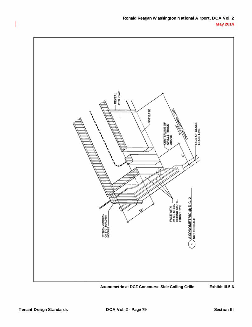
Ronald Reagan Washington National Airport, DCA Vol. 2 May 2014
Axonometric at DCZ Concourse Side Coiling Grille Exhibit III-5-6
Tenant Design Standards DCA Vol. 2 - Page 79 Section III
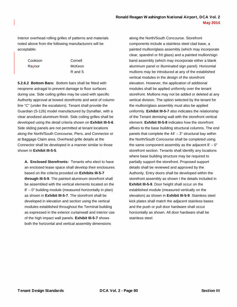
Ronald Reagan Washington National Airport, DCA Vol. 2 May 2014
Interior overhead rolling grilles of patterns and materials noted above from the following manufacturers will be acceptable:
Cookson Raynor
Cornell McKeon R and S
5.2.6.2 Bottom Bars: Bottom bars shall be fitted with neoprene astragal to prevent damage to floor surfaces during use. Side coiling grilles may be used with specific Authority approval at bowed storefronts and west of column line “C” (under the escalators). Tenant shall provide the Guardian (S-126) model manufactured by Dynaflair, with a clear anodized aluminum finish. Side coiling grilles shall be developed using the detail criteria shown on Exhibit III-5-6. Side sliding panels are not permitted at tenant locations along the North/South Concourse, Piers, and Connector or at Baggage Claim area. Overhead grille details at the Connector shall be developed in a manner similar to those shown in Exhibit III-5-5.
A. Enclosed Storefronts: Tenants who elect to have an enclosed lease space shall develop their enclosures based on the criteria provided on Exhibits III-5-7 through III-5-9. The painted aluminum storefront shall be assembled with the vertical elements located on the 8' – 0" building module (measured horizontally in plan) as shown in Exhibit III-5-7. The storefront shall be developed in elevation and section using the vertical modules established throughout the Terminal building as expressed in the exterior curtainwall and interior use of the high impact wall panels. Exhibit III-5-7 shows both the horizontal and vertical assembly dimensions
along the North/South Concourse. Storefront components include a stainless steel clad base, a painted mullion/glass assembly (which may incorporate clear, spandrel or frit glass) and a painted mullion/sign band assembly (which may incorporate either a blank aluminum panel or illuminated sign panel). Horizontal mullions may be introduced at any of the established vertical modules in the design of the storefront elevation. However, the application of additional modules shall be applied uniformly over the tenant storefront. Mullions may not be added or deleted at any vertical division. The option selected by the tenant for the mullion/glass assembly must also be applied uniformly. Exhibit III-5-7 also indicates the relationship of the Tenant demising wall with the storefront vertical element. Exhibit III-5-8 indicates how the storefront affixes to the base building structural columns. The end panels that complete the 44' – 3" structural bay within the North/South Concourse shall be completed using the same component assembly as the adjacent 8' – 0" storefront section. Tenants shall identify any locations where base building structure may be required to partially support the storefront. Proposed support details shall be reviewed and approved by the Authority. Entry doors shall be developed within the storefront assembly as shown I the details included in Exhibit III-5-9. Door height shall occur on the established module (measured vertically on the elevation) as shown in Exhibit III-5-9. Stainless steel kick plates shall match the adjacent stainless bases and the push or pull door hardware shall occur horizontally as shown. All door hardware shall be stainless steel.
Tenant Design Standards DCA Vol. 2 - Page 80 Section III

Ronald Reagan Washington National Airport, DCA Vol. 2 May 2014
Storefront NS Concourse Typical Details Exhibit III-5-7
Tenant Design Standards DCA Vol. 2 - Page 81 Section III

Ronald Reagan Washington National Airport, DCA Vol. 2 May 2014
Storefront NS Concourse Col Connection Exhibit III-5-8
Tenant Design Standards DCA Vol. 2 - Page 82 Section III

Ronald Reagan Washington National Airport, DCA Vol. 2 May 2014
Entry Doors NS Concourse Typical Details Exhibit III-5-9
Tenant Design Standards DCA Vol. 2 - Page 83 Section III

Ronald Reagan Washington National Airport, DCA Vol. 2 May 2014
B. Butt Joint Glazed Storefronts: At Food- and-beverage and Retail lease area locations along the North/South Concourse which are recessed and occur west of Col. line C, tenants may develop butt joint glazed storefronts. Butt joint glazed storefronts may only occur at recessed storefronts in the North/South plane. Storefronts, completing the lease enclosure, which occur in the East/West plane shall incorporate the vertical elements and mullion components described earlier in this sub-section. Butt joint enclosures shall be developed based on the criteria provided on Exhibit III-5-10. The following shall be noted in the development of such butt glazed enclosures as shown in Exhibit III-5-10. An 8" x 8" vertical element shall be used to turn the corner. Vertical divisions shall be developed on the 8 foot module (measured horizontally in plan) in the signband and transom as shown in the elevation detail. This vertical divider shall be constructed to structurally support the enclosing wall system. Tenants shall identify any locations where base building structure may be required to support these vertical dividers. Proposed support details shall be reviewed and approved by the Authority. Glass shall be a minimum of ½" tempered in all butt joint applications and adjacent storefront enclosures so that the color of the glazing remains consistent within the wall assembly. The 6" stainless steel base element shall be provided the full length of the storefront. Entry doors into the lease areas shall be developed within the elevation either in the East/West direction or the elevation that is along Col. line C. No doors or openings shall be permitted in the butt glazed elevation. At lease area locations along the Piers (except for at the food court), butt joint enclosures shall be developed based on the criteria provided on Exhibit III-5-11. Tenants shall confirm the location of any linear supply air diffusers that occur as part of the base building construction. Tenant butt glazed construction shall occur a minimum of 4" from
the edge of these diffusers that provide supply air to the public concourse circulation on the Piers. Butt glazed storefronts at the Pier Food Courts areas shall be developed in a manner similar to those shown in Exhibit III-5-12. Butt glazed storefronts located on the Connector shall be developed in a manner similar to those shown in Exhibit III-5-11.
C. Storefront Manufacturers: The following manufacturers shall be selected to provide storefront system that complies aesthetically with Tenant Design Standards:
1) EFCO Corporation, Inc.
2) Kawneer Company, Inc.
3) United States Aluminum, Corp.
4) Vistawall Architectural Products.
5.2.7 Lighting: Tenants are encouraged to select lighting fixtures, equipment and accessories that are consistent with the high quality level of design, materials, finishes and accessories applied throughout Terminal B/C. Daylight levels along the North/South Concourse, along the Piers, in the Connector, and at the Ticketing Level of the Piers may vary due to the availability of natural light. Tenants are encouraged to consider the use of dimmers to allow greater control of illumination levels within tenant areas.
5.2.7.1 Illuminations levels for general lighting shall comply with the following footcandle criteria in circulation areas:
A. Daytime and Nighttime: 10-30 footcandles horizontal at 3' – 0" above the finished floor Luminous ceiling or wall treatments are prohibited. No manufacturer labels or other identification are permitted on exposed surfaces.
Tenant Design Standards DCA Vol. 2 - Page 84 Section III

Ronald Reagan Washington National Airport, DCA Vol. 2 May 2014
Storefront NS Concourse Butt Glazing Details Exhibit III-5-10
Tenant Design Standards DCA Vol. 2 - Page 85 Section III

Ronald Reagan Washington National Airport, DCA Vol. 2 May 2014
Storefront Pier Butt Glazing Details Exhibit III-5-11
Tenant Design Standards DCA Vol. 2 - Page 86 Section III

Ronald Reagan Washington National Airport, DCA Vol. 2 May 2014
Butt Glazed Storefronts Pier Food Court Areas Exhibit III-5-12
Tenant Design Standards DCA Vol. 2 - Page 87 Section III

Ronald Reagan Washington National Airport, DCA Vol. 2 May 2014
5.2.7.2 Refer to tenant specific chapters for particulars by tenant type. All lighting equipment selected by tenants shall be subject to Design Review and Approval. Exposed conduit, extension cords or other exposed wiring is prohibited.
5.2.8 Signing/Graphics
5.2.8.1 General Criteria/Permanent Signage: Signing, graphics and/or display of corporate logos shall be consistent with the ambience created by the architectural design of the Terminal. Graphics design shall be lively yet clear and readable. Tenants shall be required to submit graphic materials to the Authority for Design Review and Approval to ensure the preservation of a high quality image. Materials submitted shall include size, materials, lighting, method of attachment, colors and typography for all sign bands, blade signs, wall or casework mounted graphic materials. Signage shall meet all applicable code criteria. The tenant shall use a professionally trained graphic designer to develop signage, graphics and corporate identities. These professionals shall have at least a degree in graphic design or a related design field and five years experience in the field of graphic design, preferably in the area of corporate image development/enhancement, print graphics, or environmental graphic design. Professionals shall communicate competently on issues of contrast, legibility, typefaces, viewer recognition factors, proportion and semantics of visual communication. Graphic materials submitted directly by sign fabricators will not be accepted.
5.2.8.2 Temporary Signing: Any tenant or Authority temporary signing which can be viewed from public areas shall be designed, constructed and executed with quality and professional standards of fabrication. Temporary signs will be reviewed and approved by the Authority. Temporary signs may be reviewed for sign type and/or layout depending on the application. Such signs at tenant locations include, but are not limited to, signs specifying prices, schedules, cancellations, national or local promotion, “sale” or “specials,” menu, order here, queuing instructions and designation of condiment bars, trash and/or recycling receptacles and maintenance signs or stanchions.
Tape, push pins, Velcro or other similar methods of attachment for temporary signs is prohibited. Method of attachment or display will be reviewed and approved by the Authority. Commercially produced graphics for nationally produced and merchandised products, including cardboard “dumps,” “pop-ups,” “standees, “cut-outs” or other temporary promotional displays are generally unacceptable and may not be displayed at point of sale.
5.2.8.3 Prohibitions: The following are not permitted in signing, graphic or corporate identity applications except by special review and approval by the Authority:
Exposed Neon Strobe, flashing or blinking lights Iridescent or luminous signs Externally illuminated signs Inflatable objects Mechanical, animated or kinetic signs TV monitors or any other kind of picture screen Dioramas Formed or molded plastic signs Hand-prepared or lettered placards Ceiling hung signs, banners, or objects
A. Tenants may not paint or adhere permanent or temporary decals, art work or signing indicating product line, credit card acceptability or security system warnings to columns, spandrel, or glazed storefront elements.
5.2.8.4 Manufacturer Labels: No manufacturer labels are permitted on display fixtures, lighting equipment, sign boxes or other pre-manufactured units.
5.2.8.5 Internally Illuminated Signs: No exposed ballasts are permitted.
5.2.8.6 Room Numbering: No signs, other than Terminal standard room numbering and labeling, are permitted within the public view. All sign applications to interior and exterior tenant doors will be subject to review and approval by the Authority. All tenant spaces must be shown in plan and
Tenant Design Standards DCA Vol. 2 - Page 88 Section III

Ronald Reagan Washington National Airport, DCA Vol. 2 May 2014
physically labeled with permanent room numbers. This is critical for both fire-fighting and emergency medical service staff at the Airport and for general building management. Where a tenant subdivides a numbered space, all interior spaces, corridors and rooms shall be identified with the specified permanent room number, followed by a unique alphabetic suffix to identify each separate space within the overall leasehold area. Within tenant leasehold areas, legible, permanent room numbering plaques or signs must be provided, displayed both the assigned permanent room number and room function, but each tenant may determine their own standard for such signs.
5.2.8.7 Letter Size: Minimum lettering size is ⅝" capital letters. Maximum proposed letter height will be reviewed and approved by the Authority.
5.2.8.8 Hours of Operation: Presentation of “Hours of Operation” shall be standard application of vinyl to glass sub-surface signing as specified in Exhibit III-5-13. No “open/closed” signs may be posted.
5.2.8.9 Credit Card Acceptability: Credit card acceptance signs shall be displayed at cash registers/point of sale. Silk-screened or vinyl art work on clear acrylic shall be mounted to the register or on a low profile adjacent surface. Maximum sign area shall be 8" x 10".
5.2.8.10 Brochure Displays: Tenants who wish to offer or display brochures, bag tags or other literature at any location shall procure clear acrylic easels or holders. Maximum overall dimension shall be 8½" x 11". Such fixtures may not be affixed to any casework either on a permanent or semi-permanent basis. Tenants shall review samples of their brochure displays with the Authority prior to procuring for Terminal-wide use.
5.2.8.11 Sign Bands: Use of internally illuminated sign application is limited to storefront sign bands and blade signs. Except for common sign bands, no permanent or temporary signing, graphic and/or displays or corporate logos may be fastened to the base building elements by the tenant.
5.2.8.12 Advertising: Refer to Chapter 9 for additional information.
5.2.9 Merchandising Displays: Materials used in displays within the Design Control Zone shall conform to the criteria set forth above except by special review and approval by the Authority.
5.2.9.1 Display lighting shall be provided for the express purpose of highlighting merchandise in display windows. Acceptable lighting equipment for display lighting include:
A. Recessed or track mounted incandescent adjustable fixtures for MR 16 or PAR 36 low voltage lamps with integral step down transformer and accessories.
B. Recessed or track mounted incandescent adjustable fixtures for PAR-20 or PAR-30 lamps and accessories.
5.2.9.2 Adjustable lighting equipment within the Design Control Zone and remaining tenant areas must be positioned or shall have accessories to eliminate glare into public areas of the terminal. Special attention to the use of mirrored surfaces will also be required to prevent reflected light and/or reflection of exposed bulbs.
Tenant Design Standards DCA Vol. 2 - Page 89 Section III

Ronald Reagan Washington National Airport, DCA Vol. 2 May 2014
Hour of Operation, Signing and Graphics Criteria Exhibit III-5-13
Tenant Design Standards DCA Vol. 2 - Page 90 Section III

Ronald Reagan Washington National Airport, DCA Vol. 2 May 2014
Use of decorative neon accent lighting within tenant displays may be approved by the Authority. Design review and approval will be required prior to fabrication and installation. Lighting equipment selected by tenants for display lighting for merchandise areas will be subject to design review and approval by the Authority.
5.2.10 Fixtures/Furnishings/Equipment: Fixtures, furnishings and equipment, including, but not limited to, furniture, casework, millwork, kitchen and other equipment, display units, hand or guard rails and other accessories are visual elements whose placement, either within the Design Control Zone or in other lease areas which can be viewed from public circulation areas, should be given special consideration by the tenant. Fixtures and furnishings shall have a custom integrated appearance. Unfinished, exposed surfaces on any off-the-shelf or custom fabrication or construction are unacceptable. Selection, design of, and placement of such items, whether permanently affixed or movable, will be reviewed and approved by the Authority. Mobile equipment shall have factory or manufacturer installed bumpers on all exposed edges and semi-inflatable tires to prevent damage to interior wall and floor finishes. Casework and millwork construction shall comply with criteria contained in the Design Manual. Casework or millwork used to display or store goods shall be lockable. Loose fixtures or equipment shall be securable or storable. No used furnishings, fixtures or equipment are permitted if they can be viewed from public areas. Furnishings, fixtures and equipment shall be maintained in good working order.
5.2.10.1 Anti-fatigue Mats: Anti-fatigue mats provided by the Authority at locations noted shall be replaced by the tenant to match the original standard.
5.2.10.2 Miscellaneous Mobile Equipment: Any loose equipment used by any tenant or contract employee thereof within public areas in and around the terminal will be reviewed and approved by the Authority. Such equipment includes, but is not limited to hand carts, “bellman” carts, luggage carts, dollies, bus carts or stations, and wheelchairs. Such mobile equipment shall have factory or manufacturer installed bumpers on all exposed edges and
semi-inflatable tires to prevent damage to interior and exterior wall and floor finishes.
5.2.10.3 Vending Machines: Vending machines that are viewed from public areas are prohibited.
5.2.11 Window Treatment at Exterior Curtainwall
5.2.11.1 To ensure a uniform appearance of Terminal B/C, exterior curtainwall treatment at tenant lease areas shall be selected from the following options:
A. Clear anodized perforated aluminum horizontal blinds.
B. ThermoVeil Shade cloth by MechoShade Systems, 1300 Dense Basket Weave, 5% openness factor, in Color No. 1316 “Eggshell”.
5.2.11.2 Window Treatments shall be mounted in sections that match the vertical mullion spacing. Window treatments shall be surface mounted. Tenant construction shall create horizontal pockets to receive the mounting. Proposed installation details must be reviewed and approved by the Authority.
5.2.12 Floor and Roof Structure: Tenants shall verify loading conditions created by the installation or suspension of tenant provided equipment or systems that may result in concentrated loads greater than, 200 lbs on the roof and 500 lbs on the floor structures. The indicated concentrated load shall be assumed to occupy an area of 2.5' x 2.5' square . Any concentrated loads suspended from the overhead structure shall be suspended from either beams or purlins.
5.2.12.1 Antennas: Antennas shall only be permitted at Authority designated locations associated with equipment rooms dedicated to radio communications. All tenant installed antennas shall be reviewed and approved by the Authority.
Tenant Design Standards DCA Vol. 2 - Page 91 Section III

Ronald Reagan Washington National Airport, DCA Vol. 2 May 2014
5.2.13 Mechanical (HVAC): Tenants shall not use refrigeration equipment utilizing water cooled condensers that reject heat to cooling towers or to potable water systems. Refrigeration equipment shall be served by air-cooled condensers or condensers that utilize the building chilled water system. The chilled water system may be used in water cooled condenser, where chilled water is available, with the prior approval of the Authority. All tenant installed outside air systems and exhaust fans shall be coordinated with the Authority. Tenants shall balance their air distribution system to meet Authority requirements. Each space, other than kitchen and toilet facilities shall be designed to maintain a 5% positive pressure. All areas approved by the Authority as designated smoking areas shall be independently served and exhausted by the tenant such that no tobacco contaminated air is returned to Authority/base building air handling units. This requires that 100% of the return air from the dedicated smoking area be exhausted to the outside. Exhaust ducts shall be installed in the tenant space by the tenant between the exhaust fan and the exterior wall. All equipment, ducts, fans and appurtenances shall be supplied and installed by the tenant. Any tenant exhaust fans and systems installed on exterior walls must be reviewed and approved by the Authority prior to installation. All air supplied or transferred to designated smoking areas shall be exhausted directly to the outdoors without recirculation. Tenants may not install roof-mounted exhaust fans or packaged mechanical units without approval of the Authority. The location of, method of attachment, penetration and visual appearance of any mounted exhaust fans installed on exterior walls shall be reviewed and approved by the Authority.
5.2.14 Fire Suppression/Life Safety/Smoke Exhaust: Where independent or supplemental HVAC systems are provided by the tenant, the following criteria shall apply:
5.2.14.1 Smoke Evacuation Systems: Smoke evacuation systems in all tenant areas shall be provided by the tenant in accordance with International Building Code and International Mechanical Codes and as approved by the Authority. The smoke evacuation exhaust system shall
be designed to maintain a minimum of four air changes per hour.
5.2.14.2 Tenant Provided Fire Life Safety Systems: Tenant provided fire life safety system shall be compatible with the system provided by the Authority for the terminal.
5.2.14.3 Smoke Detectors: A smoke detector shall be provided by the tenant in the return air duct ahead of the outdoor air intake for systems of 2,000 cfm or greater and at the fan discharge of each air handling system having a capacity of 15,000 cfm or greater along with a smoke damper. When a smoke detector or fire life safety system is energized, the supply fan will stop. The return fan will go into exhaust mode. The fire marshal may manually energize the system from the fire alarm panels.
5.2.14.4 Tenant Provided Smoke Exhaust Systems: Tenant provided smoke exhaust systems shall function as follows. When a fire occurs within any area, the air handling system shall operate at 100% exhaust and the supply air system shall shut down.
5.2.14.5 Fan Coil Units: For tenant areas served by Fan-Coil Units, such units shall be designed to shut down when a fire occurs in the area. Tenant provided smoke exhaust fans will be activated to provide 100% exhaust. Tenants shall provide visual and audible notification devices for connection to the building fire alarm system complying with NFPA 72 and ADA. Tenant provided fire suppression system shall be connected to the building fire alarm system for annunciation. Tenants shall be responsible for all tie-in connections to the building life safety system.
5.2.14.6 Tenant Fire Extinguishers: Tenants shall provide and install ABC type portable fire extinguishers for every 3,000 sq. ft. of tenant lease area. The extinguishers shall be multi-purpose chemicals, 20 BC:10 C, UL rated.
5.2.14.7 Fume Exhaust Hoods: All cooking surfaces, grills, ranges, ovens and similar equipment shall be provided with a fume exhaust hood. The hood shall be
Tenant Design Standards DCA Vol. 2 - Page 92 Section III

Ronald Reagan Washington National Airport, DCA Vol. 2 May 2014
provided with a pre-engineered approved type fire suppression system automatically and manually activated.
5.2.14.8 Hood Electrical Control: The hood electrical control panel shall be provided with two sets of dry contacts for remote alarm and controls that shall interface with the building fire alarm system. Tenants shall provide required cables, devices and interface point to the fire alarm system.
5.2.15 Decorations: The Authority will be responsible for seasonal and holiday decorations within the Terminal. Individual seasonal or holiday displays, if desired by the tenant for installation inside the tenant space, shall be professionally designed and reviewed with the Authority prior to installation.
5.2.16 Interior Landscaping: Living and artificial plants in tenant spaces which can be viewed from public areas are prohibited. Other tenant provided interior landscaping, including living and artificial trees, plants and flowers, shall be approved by the Authority.
5.2.17 Music: Background music is permitted in tenant areas on either a temporary or permanent basis provided it is not audible in adjacent public or tenant areas.
5.2.18 Queue Control/Stanchions: Tenants shall be responsible for controlling individual queues within or immediately adjacent to their lease premise so that customer queues do not interfere with circulation. Tenants shall procure, store and have available for immediate use queue control devices. Such devices shall be employed any time that excessive queues may form.
5.2.18.1 Queue control devices shall be of one type and shall be as follows or approved equal:
A. Beltway Magnum Queuing System by Brass Smith.
5.2.18.2 The stanchion shall be a satin finish stainless steel post with a satin finish stainless steel head except at the Ticketing Level lobby. Tenants may select any solid
color for the tape with the exception of green. No stripes, graphics or typography will be permitted on the tape. The Authority will provide queue stanchions and tape for the Ticketing Level lobby. Plexiglass signs attached to the post head shall be the same color as the tape chosen. Sign frame and attachment shall be from same manufacturer. No mixing and matching of stanchions and sign applications are permitted. Signs shall conform to the criteria noted above.
5.2.19 Signing/Graphics Outside of Lease Area: Where ad stanchions, sign stanchion or poster/brochure racks are available or used, tenants shall be required to use a professionally trained graphic designer to develop their advertising inserts. Graphic materials will be approved by the Authority prior to installation in the stanchion unit.
5.2.20 Aesthetic Treatment of Exposed Pipe: Where box building exposed piping occurs in a tenant space, tenants shall cover these pipes with uniformly sized metal pipe sleeves or shroud in accordance with Exhibits III-5-14 and III-5-15.
5.3 Enforcement
5.3.1 General: Any tenant installed items that do not conform to this criteria or for which prior authorization through the Authority review and approval process was not received may be removed by the Authority. Any costs associated with removal of installed items will be reimbursed to the Authority by the tenant.
Tenant Design Standards DCA Vol. 2 - Page 93 Section III

Ronald Reagan Washington National Airport, DCA Vol. 2 May 2014
Exposed Pipe, Aesthetic Treatment Exhibit III-5-14
Tenant Design Standards DCA Vol. 2 - Page 94 Section III

Ronald Reagan Washington National Airport, DCA Vol. 2 May 2014
Pipe Shroud Exhibit III-5-15
Tenant Design Standards DCA Vol. 2 - Page 95 Section III

Ronald Reagan Washington National Airport, DCA Vol. 2 May 2014
(This Page Blank)
Tenant Design Standards DCA Vol. 2 - Page 96 Section III

Ronald Reagan Washington National Airport, DCA Vol. 2 May 2014
CHAPTER 6 Airline Tenant Design Standards
6.1 Locations Governed By Tenant Design Standards
6.1.1 General: Airline tenant locations are identified in the most current version of the Space Assignment Drawings. In Terminal B/C, departures or Ticketing Level spaces include exclusive use ticket counter frontage and backwall area, adjacent airline ticket office spaces, and curbside check-in areas located on the curb. Adjacent to the non-secure departures level are secure club areas that are located on the upper levels of the Piers and Connector. On the Concourse Level, which serves the aircraft gates, locations governed by the standards include hold rooms (departure lounges), gate counters, backscreens and ticket lift podiums, airline offices, check-in podiums at the end of each bridge, and shuttle ticket counters. Locations on the arrivals or Baggage Claim Level include baggage service offices, common-use baggage claim areas, and airline operation spaces at the apron level of the three Piers, four-gate Connector, and the inbound and outbound baggage areas.
6.2 General Criteria/Prohibitions
6.2.1 Telecommunications and Special Systems
6.2.1.1 Telecommunications: Airline tenants are not permitted to cable between the piers and airline clubs or between the piers and ATO offices. Connectivity between these locations shall be via the Authority provided cable system. Airline tenants shall be required to route all low voltage communications cable in conduits or on cable trays. No exposed cable will be permitted in ceilings or walls. Airline tenants shall not be permitted to use Authority installed cable trays for installation of airline cable. Airlines must obtain Authority approval for routing of conduit through non-airline spaces.
6.2.1.2 Multi-User Flight Information Display System (MUFIDS): Airline tenants shall update their own flight information in the MUFIDS system. Updates may be made
via a MUFIDS edit terminal, a host interface or an interface from another FIDS system. Airline tenants shall be responsible for the procurement of edit terminals or MUFIDS interface. Airline tenants shall provide camera-ready art work of their corporate logo, appropriate for scanning, for insertion into the MUFIDS system. Should airline tenants elect to install additional monitors serviced from the Terminal B/C MUFIDS system in their exclusive use areas, the Authority will provide the MUFIDS data signal to the network demarcation point in their space. The airline tenant shall be responsible for the procurement and installation of monitors and associated interface equipment that is compatible with the Terminal B/C system.
6.2.2 Music: Background music is permitted in tenant areas on either a temporary or permanent basis provided it is not audible in adjacent public or tenant areas.
6.2.3 Signing/Graphics
6.2.3.1 Tenant Signage: Tenants shall be responsible for individual signing and/or corporate logo application at the following locations as specified in these standards:
A. Backwall within curbside check-in alcove.
B. Curbside Check-in Podium.
C. Bridge Check-in Podium.
D. Backwall behind ticket counter.
E. Gate Counter Backscreen.
F. At elevator, stairs and other entrances to airline clubs.
G. BID screen at baggage claim.
H. Baggage service office storefront.
I. In poster/brochure racks.
Tenant Design Standards DCA Vol. 2 - Page 97 Section III

Ronald Reagan Washington National Airport, DCA Vol. 2 May 2014
J. On advertising under separate agreement.
6.2.3.2 Airline Name: Airline name may appear in corporate typeface with logos and corporate colors. Only one airline name per sign panel will be allowed, except as provided in Paragraph 6.4.2. Materials and mounting provisions vary by location. Tenants shall submit all proposed graphic materials indicating the location, size, materials, lighting, colors, typography, and method of attachment for all tenant provided signing, graphics or corporate logos to be used within the tenant area to the Authority for review and approval. Any display of permanent or temporary signing at any tenant location specifying special airline promotions, pricing or schedule must be designed, constructed and executed with quality and professional standards of fabrication and shall comply with Chapter 5. Such temporary signing will be reviewed and approved by the Authority prior to fabrication or display. Corporately produced graphics and proposed location and method for display for national or local promotions will be reviewed and approved by the Authority prior to permanent or temporary display.
6.3 Curbside Check-In
6.3.1 General Criteria: Curbside check-in areas have been established at six locations along the enplaning or ticketing roadway as generally indicated on Exhibit III-6-1. Tenants have the option to furnish and install one or two podiums at each curbside area. Options include one 6' -5½" podium, two 6' -5½" podiums or one 10' – 0" podium as required to serve their operation. Exhibits III-6-1 and III-6-2 indicate prototypical plan conditions for these options. Tenants shall furnish and install check-in podiums as described in the design criteria shown on Exhibits III-6-2 through III-6-4. Further details and material hardware specifications may be found in the Contract Documents for the Casework Construction Package. Corrugated stainless steel (SST #2), as required for fabrication of podium, will be provided to the tenants by the Authority. Tenants shall be responsible for the reimbursement of their stainless steel
costs to the Authority. Tenants shall verify the specific conditions of their individual lease area at these locations with the most current terminal building documents available through the Authority and/or through inspection of existing conditions. Each check-in location is provided with an adjacent storage area for storage of hand carts, cartons, tubs, plastic bags, and other items associated with curbside check-in activities. Curbside check-in areas will be secured when not in use through the use of an overhead roll-down locking door provided by the Authority as shown in Exhibits III-6-4 and III-6-5.
6.3.2 Podium Locations: Curbside podiums procured by the airlines shall be placed as shown on Exhibits III-6-1 and III-6-2. The face of the podium shall be approximately 9' – 4" from the centerline of Column Grid A. At a minimum, a passage of 5' – 0" clear shall be maintained between the agent edge of the counter and the face of the building. The tenant shall control the queue of airport patrons so that a minimum of 6 feet is maintained for general circulation at the curb in front of the check-in area. This queue zone is delineated in Exhibit III-6-2. Queue control, if required, shall be as described in Chapter 5.
6.3.3 Signing/Graphics: Overhead signing at the curbside will be provided by the Authority using Exhibit III-6-4 as a guideline. Tenants may display airline identification and/or corporate logos at the back wall of the alcove as indicated in Exhibit III-6-3 and/or on the check-in podium as indicated in Exhibit III-6-6. Tenant signing shall meet the following design criteria:
6.3.3.1 Podium: Airline identification signing on the podium shall be acid etched, color filled or silk-screened on a stainless steel panel with a #4 finish. The Airline name may be in the font, style, size and color of their choice. The dimensions of the panels will vary in width depending on the size podium required by the tenant. Signing shall be provided by the tenant in conjunction with the construction of the curbside unit.
Tenant Design Standards DCA Vol. 2 - Page 98 Section III

Ronald Reagan Washington National Airport, DCA Vol. 2 May 2014
Curbside Check-In Options Exhibit III-6-1
Tenant Design Standards DCA Vol. 2 - Page 99 Section III

Ronald Reagan Washington National Airport, DCA Vol. 2 May 2014
Curbside Check-In, Typical Plan Exhibit III-6-2
Tenant Design Standards DCA Vol. 2 - Page 100 Section III

Ronald Reagan Washington National Airport, DCA Vol. 2 May 2014
Curbside Check-In, Typical Elevation Exhibit III-6-3
Tenant Design Standards DCA Vol. 2 - Page 101 Section III

Ronald Reagan Washington National Airport, DCA Vol. 2 May 2014
Curbside Check-In, Typical Section Exhibit III-6-4
Tenant Design Standards DCA Vol. 2 - Page 102 Section III

Ronald Reagan Washington National Airport, DCA Vol. 2 May 2014
Curbside Check-In, Overhead Door Exhibit III-6-5
Tenant Design Standards DCA Vol. 2 - Page 103 Section III

Ronald Reagan Washington National Airport, DCA Vol. 2 May 2014
Curbside Check-In, Podium Elevation Exhibit III-6-6
Tenant Design Standards DCA Vol. 2 - Page 104 Section III

Ronald Reagan Washington National Airport, DCA Vol. 2 May 2014
6.3.3.2 Backwall: Airline identification and/or corporate logo display on the back wall of the alcove shall be limited to a 2' x 8' zone as typically described in Exhibit III-6-3. The actual location of such signing may vary at each curbside area due to the location of the baggage belt presentation area and belt decline.
6.3.3.3 Prohibitions: No signing or graphics is permitted on the roll down door as shown in Exhibit III-6-5, on the door to the adjacent storage area or any other adjacent surface.
6.3.3.4 FAA Required Signage: FAA required signage at the curbside podium shall comply with Paragraph 6.12.7.
6.3.4 Casework: Curbside podiums shall be constructed by the airlines to meet the design criteria established by elevation, section and details described in Exhibits III-6-6 through III-6-8. Airlines shall refer to the Casework Construction Documents for further similar details.
6.3.5 Anti-Fatigue Mats: Anti-fatigue mats shall be provided by the airlines at the employee or agent side of the podium if desired by the airlines. Anti-fatigue mats shall be reviewed and approved by the Authority prior to installation. Airlines shall refer to the Casework Construction Documents for anti-fatigue mat options.
6.4 Airline Ticket Counters And Backwalls
6.4.1 General Criteria: Ticket counter frontage and baggage wells have been developed in the ticketing lobby along the structural bay spacing. Each 44' – 3" structural bay will accommodate nine agent positions and adjacent baggage wells as described in Exhibits III-6-9 through III-6-13. The tenant shall provide all inserts, equipment, wiring and agent-side counter tops. Airlines shall refer to the Casework Construction Documents for further similar details. The agent-side counter tops shall be constructed of plastic laminate, the color of which shall match Westinghouse Micarta Color No. 91M54 E Weathered
Gray, Texture “Velvet”. The ticket counter side enclosures have been trimmed in stainless steel. All tenant provided counter tops shall be installed to ensure that unfinished interior surfaces of the casework at the sides and back are enclosed from view. Tenants shall verify the specific conditions of their individual lease area at ticket counter locations with the most current Terminal Casework Construction Package documents available through the Authority and/or through inspection of field conditions to ensure suitability of their individual inserts. Tenants shall control the queue of airport patrons in the ticketing lobby so that general circulation is maintained beyond the line of passengers using the ticket counter, and shall be maintained through the use of queuing stanchions. The airline must have available queue control stanchions to employ during any and all scheduled peaks or unanticipated delays when excessive queues may form. Queuing stanchions shall conform to the criteria established in Chapter 5.
6.4.2 Signing/Graphics: Overhead signing at the ticket counter will be provided by the Authority using Exhibits III-6-9 and III-6-10 as a guideline. Tenants may display airline identification and/or corporate logos at the back wall behind the counter as indicated in Exhibit III-6-14. Tenant signing shall meet the following design criteria:
6.4.2.1 Backwall: The back wall behind the ticket counter will be a high impact wall panel system with a horizontal module provided by the Authority. Airline logos and corporate identities may be developed on a tenant provided panel of the dimensions indicated in Exhibit III-6-14. The tenant provided panel shall be inserted into the panel system grid using the panel system grid. The corporate image panel or panels will be uniformly flush mounted as described in Exhibit III-6-14. Such signs shall be non-illuminated with materials, typography, logo size or colors to be selected by the tenant and developed within the panel dimensions indicated. The airline identification and/or corporate logo may be displayed in as many panels as are contained in tenant lease area.
Tenant Design Standards DCA Vol. 2 - Page 105 Section III

Ronald Reagan Washington National Airport, DCA Vol. 2 May 2014
Curbside Check-In, Podium Side Elevation Exhibit III-6-7
Tenant Design Standards DCA Vol. 2 - Page 106 Section III

Ronald Reagan Washington National Airport, DCA Vol. 2 May 2014
Curbside Check-In, Podium Details Exhibit III-6-8
Tenant Design Standards DCA Vol. 2 - Page 107 Section III

Ronald Reagan Washington National Airport, DCA Vol. 2 May 2014
Ticket Counters, Typical Elevation Exhibit III-6-9
Tenant Design Standards DCA Vol. 2 - Page 108 Section III

Ronald Reagan Washington National Airport, DCA Vol. 2 May 2014
Ticket Counters, Doghouse Elevation Exhibit III-6-10
Tenant Design Standards DCA Vol. 2 - Page 109 Section III

Ronald Reagan Washington National Airport, DCA Vol. 2 May 2014
Ticket Counter Elevation, 2-Position Elevation Exhibit III-6-11
Tenant Design Standards DCA Vol. 2 - Page 110 Section III

Ronald Reagan Washington National Airport, DCA Vol. 2 May 2014
Ticket Counter Elevation, 2-Position Plan Exhibit III-6-12
Tenant Design Standards DCA Vol. 2 - Page 111 Section III

Ronald Reagan Washington National Airport, DCA Vol. 2 May 2014
Ticket Counter Elevation at Bagwell Exhibit III-6-13
Tenant Design Standards DCA Vol. 2 - Page 112 Section III

Ronald Reagan Washington National Airport, DCA Vol. 2 May 2014
Ticket Counter at Backwall Exhibit III-6-14
Tenant Design Standards DCA Vol. 2 - Page 113 Section III

Ronald Reagan Washington National Airport, DCA Vol. 2 May 2014
Display of Airline identification behind the ticket counter at the baggage belt decline enclosure (doghouse), as shown in Exhibit III-6-14, may be considered on a case-by-case basis with review and approval of the Authority in context with use of ATM and overall lease frontage. Airlines with marketing partners or code share agreements may display more than one Airline name per sign panel, however, the primary airline name must appear in at least 50% of the overall sign area. Such shared Airline identification or signage shall be reviewed and approved by the Authority. No additional signing, graphics and/or display of corporate logos will be permitted on the ticket counter casework, baggage wells or baggage belt decline enclosures in the ticketing lobby. Monitors may not be incorporated into the backwall at the ticket counter.
6.4.2.2 Banners: Banners are only allowed on the ATO Backwall. Banners must be supported by “banner support hooks” located immediately above the backwall sign. Banners shall not exceed the limits of backwall signage panels. Refer to Exhibits III-6-14 and III-6-15. Banners must be reviewed and approved by the Authority prior to installation for compliance with the Tenant Design Standards. Refer to Paragraph 5.2.8.
6.4.2.3 Queue Control Signing: Tenant provided inserts to the Authority provided Visiontron four-sided rotating sign shall be sized to fit the Airport insert area. Color shall match Visiontron standard dark burgundy. Lettering will be white vinyl lettering from Visiontron standard layout OTC series.
6.4.3 Automatic Ticket Sales Machines: Tenants who desire Automatic Ticket Sales Machines at the Ticket Counter shall review proposed locations and treatment of same with the Authority. Automatic ticket sales machine locations have been designated at either end of the three ticket counter areas. The Authority will review and approve the use of Automatic Ticket Sales Machines in these locations. Tenants shall refer to Paragraph 6.5.3 for guidelines.
6.5 Shuttle Ticket Counters And Backwalls
6.5.1 General Criteria: Shuttle ticket counter frontage and baggage wells have been developed at the Center Pier and South Pier along the structural bay spacing as described in Exhibits III-6-15 through III-6-17. The tenant shall provide all inserts, equipment, wiring and agent-side counter tops. The agent-side counter tops shall be constructed of plastic laminate, the color of which shall match Westinghouse Micarta Color No. 91M54 E Weathered Gray, Texture “Velvet.” The ticket counter side enclosures have been trimmed in stainless steel. All tenant provided counter tops shall be installed to ensure that unfinished interior surfaces of the casework at the sides and back are enclosed from view. Tenants shall verify the specific conditions of their individual lease area at shuttle ticket counter locations with the most current terminal building and casework documents available through the Authority and/or through inspection of field conditions to ensure suitability of their individual inserts. Tenants shall control the queue of airport patrons immediately adjacent the shuttle counter so that general circulation is maintained beyond the line of passengers using the counter and to ensure unrestricted flow to the security check points, neighboring leaseholds or circulation to other gate areas. The queue zone is delineated on Exhibits III-6-15 and III-6-17 and shall be maintained through the use of queuing stanchions. Queuing stanchions shall conform to the criteria established in Chapter 5.
6.5.2 Signing/Graphics: Tenants may display airline identification and/or corporate logos at the back wall behind the shuttle counter as indicated in Exhibits III-6-15 and III-6-17.
6.5.2.1 Backwall: Tenant signing shall meet the design criteria established in Paragraph 6.4.2.
6.5.2.2 Queue Control Signing: Queue control signing shall be as described in Paragraph 6.4.2.
Tenant Design Standards DCA Vol. 2 - Page 114 Section III
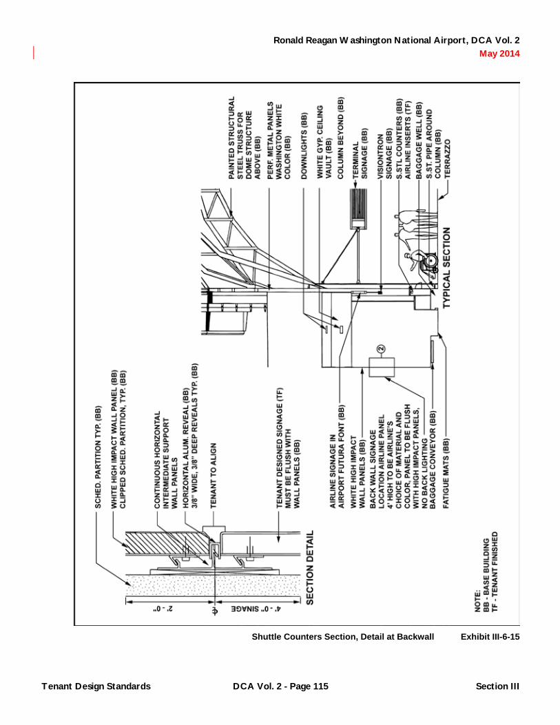
Ronald Reagan Washington National Airport, DCA Vol. 2 May 2014
Shuttle Counters Section, Detail at Backwall Exhibit III-6-15
Tenant Design Standards DCA Vol. 2 - Page 115 Section III

Ronald Reagan Washington National Airport, DCA Vol. 2 May 2014
Shuttle Ticket Counters, South Pier Exhibit III-6-16
Tenant Design Standards DCA Vol. 2 - Page 116 Section III

Ronald Reagan Washington National Airport, DCA Vol. 2 May 2014
Shuttle Ticket Counter Exhibit III-6-17
Tenant Design Standards DCA Vol. 2 - Page 117 Section III

Ronald Reagan Washington National Airport, DCA Vol. 2 May 2014
6.5.3 Automatic Ticket Sales Machines: At the Center Pier, free-standing, automatic ticket machines shall be provided by the tenant, mounted to the continuous base platform provided by the Authority contiguous with the ticket counter frontage. At the South Pier, provisions will be made for the insert of tenant provided free-standing, automatic ticket machines. Tenants shall verify the specific conditions of such areas provided in their individual lease area at shuttle ticket counter locations with the most current terminal building and casework Contract Documents available through the Authority and/or through inspection of field conditions to ensure suitability of their individual automatic ticket machine inserts. Exhibits III-6-15 and III-6-17 describe the design criteria with which any such inserts shall be incorporated into the facility. The tops of the equipment shall align with the horizontal module. The exposed surfaces of the equipment shall be stainless steel and shall be inserted such that they are flush with the adjacent high impact wall panel or adjacent casework. Signing shall be uniform and shall be non-illuminated with materials, typography, logo size or colors to be selected by the tenant to conform to Chapter 5. ADA plaques shall also be provided. Proposed automatic ticket machines and signage shall be reviewed and approved by the Authority prior to installation. The tenant shall provide doors as required to service the tenant provided equipment.
6.6 Bridge Check-In
6.6.1 General Criteria: Provisions have been made in the terminal to accommodate baggage check-in at each pedestrian bridge entering the Terminal from the parking structures and Metro station. Two podium locations on either side of the Metro bridges with associated baggage take away belts and storage areas may be developed as shown in Exhibits III-6-18 and III-6-19. Tenants shall control the queue of airport patrons immediately adjacent to the podiums at the bridges so that general access to and from the terminal and to and from escalators and elevators is maintained beyond the line of passengers using the podium. The queue zone is delineated on Exhibit III-6-18 and shall be maintained through the use of queuing
stanchions. Queue control shall be as described in Chapter 5. Each bridge check-in location is provided with a storage area. Tenants shall store hand carts, cartons, tubs, plastic bags and other items associated with baggage check-in activities in this area. The baggage conveyor shall be secured when not in use through the use of a roll-down locking door provided at the belt by the Authority.
6.6.2 Signing/Graphics: Overhead signing will be provided by the Authority as shown in Exhibit III-6-19. No other airline identification and/or display of corporate logo is permitted at this location either on the door to or wall of the adjacent storage area or on any conveyor equipment or closure.
6.6.3 Casework: Bridge check-in podiums will be of a design vocabulary similar to the curbside check-in podiums. Bridge check-in podiums shall be constructed by the airlines to meet the design criteria established by elevation, section and details described in Exhibits III-6-6 through III-6-8. Corrugated stainless steel (SST #2), as required for fabrication of podium, will be provided to the tenants by the Authority. Tenants shall be responsible for the reimbursement of their stainless steel costs to the Authority. The tenant shall provide all inserts, equipment, wiring and agent-side counter tops. The agent-side counter tops shall be constructed of plastic laminate, the color of which shall match Westinghouse Micarta Color No. 91M54 E Weathered Gray, Texture “Velvet.” The podium counter side enclosures shall be trimmed in stainless. All tenant casework construction and equipment shall be installed to ensure that unfinished interior surfaces of the casework at the sides and back are enclosed from view.
6.7 Clubs
6.7.1 Design Control Zone: Airline clubs are located one level above the Concourse Level on the Piers. The clubs are directly across from the Ticketing Level lobby and have perimeter walls that face both the ticketing lobby and the airside. The airside perimeter wall is a clear glass curtainwall from floor to ceiling.
Tenant Design Standards DCA Vol. 2 - Page 118 Section III

Ronald Reagan Washington National Airport, DCA Vol. 2 May 2014
Bridge Check-In Plan at North Bridge Exhibit III-6-18
Tenant Design Standards DCA Vol. 2 - Page 119 Section III

Ronald Reagan Washington National Airport, DCA Vol. 2 May 2014
Bridge Check-In Section Exhibit III-6-19
Tenant Design Standards DCA Vol. 2 - Page 120 Section III

Ronald Reagan Washington National Airport, DCA Vol. 2 May 2014
Access to the Club Level has been provided by both stairs and elevators that serve a common Club Level lobby that overlooks the circulation area of the concourse below. Design Control Zones have been established for the perimeter of the club and lobby entry area. Tenants are encouraged to review any individual design concerns regarding the Design Control Zone for the perimeter of the club and lobby entry area with the Authority prior to initiating design work, as well as during the development of their planning and Contract Documents to ensure that their final design meets with the approval of the Authority. Exhibit III-6-20 describes the Design Control Zone at a somewhat typical pier location. The Design Control Zone typically extends from a column line to the face of the curtainwall. The dimension of this zone varies as noted on Exhibit III-6-20. Architectural treatment in the zones identified shall be limited to the design criteria established by these standards. Tenants shall review the most current Terminal building Contract Documents available from the Authority and/or inspect actual conditions to ensure that the design of club spaces is coordinated with anticipated or existing conditions. Tenant infill construction shall be coordinated with anticipated or actual architectural details at all locations where tenant infill meets base building conditions. The following general design criteria apply to construction and finishes within the Design Control Zone along Column Line D.1 and the perimeter airside curtainwall. These design criteria shall apply to the Design Control Zone at Column Line D.1, unless the opaque façade option is developed.
6.7.1.1 Any interior partitions desired by the tenant parallel to Column Line D.1 or the perimeter airside curtainwall shall be located at the edge of or fully outside the Design Control Zone.
6.7.1.2 Any window wall mullion system not finished as part of the base building shall be painted “Washington White” to correspond to adjacent terminal construction.
6.7.1.3 All columns that fall within the perimeter Design Control Zone at Column Line D will be painted Creamy Yellow.
6.7.1.4 All columns which fall within the perimeter Design Control Zone at Column Line D.1 will be painted to match Benjamin Moore color #967.
6.7.1.5 No signing or corporate graphics is permitted either on the window wall at Column Line D.1 or on any surface immediately adjacent the wall which would allow the sign or graphic to be viewed from the concourse below, or ticketing level immediately across the concourse.
6.7.1.6 No signing or corporate graphics is permitted either on the perimeter airside curtainwalls or on any surface immediately adjacent the walls which would allow the sign or graphic to be viewed from the airside.
6.7.2 Options at Column Line D.1: In an effort to bring harmonious aesthetics to the interior window wall along the length of the North/South concourse, the following criteria have been established for this wall. Airline clubs may have a portion of or a full 44' – 3" structural bay with exposure to the North/South Concourse. The tenant is encouraged to consider the views to the interior of the Terminal as well as the views to the exterior apron, Potomac River and Federal core when preparing space plans of this area. The wall runs along Column Line D.1 as identified on Exhibit III-6-20. An 8' high portion of the wall shall be developed by the tenant as part of their tenant construction as described in Exhibit III-6-21. This portion of the wall will be provided with clear glass as part of the Terminal Construction Package. Design criteria for subsequent changes to the Authority provided clear glass include the following:
6.7.2.1 The tenant shall develop this section using the vertical and horizontal modules already established by the building architecture. Typical club wall sections are indicated on Exhibit III-6-25.
6.7.2.2 The window wall mullion system shall be painted “Washington White” to correspond to adjacent terminal construction.
Tenant Design Standards DCA Vol. 2 - Page 121 Section III
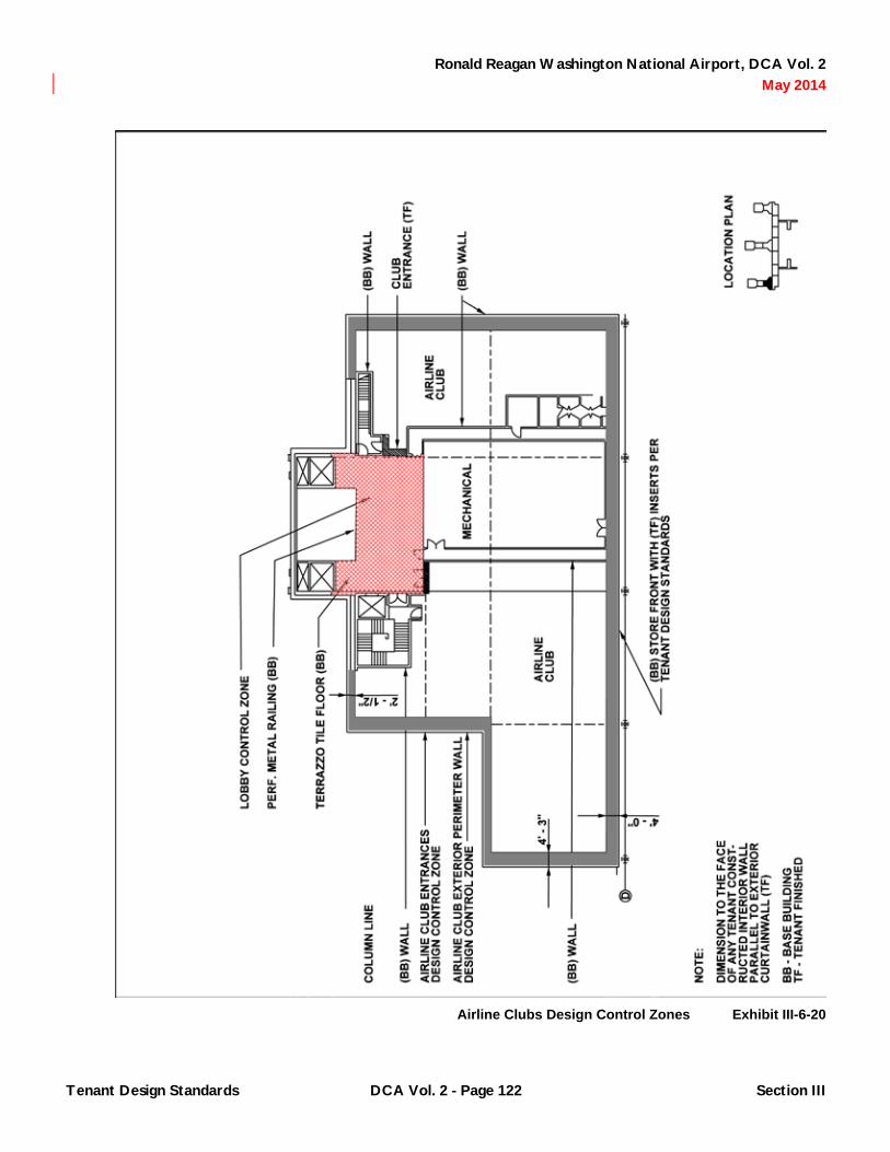
Ronald Reagan Washington National Airport, DCA Vol. 2 May 2014
Airline Clubs Design Control Zones Exhibit III-6-20
Tenant Design Standards DCA Vol. 2 - Page 122 Section III

Ronald Reagan Washington National Airport, DCA Vol. 2 May 2014
Airline Clubs Elevation at Interior Facade Exhibit III-6-21
Tenant Design Standards DCA Vol. 2 - Page 123 Section III

Ronald Reagan Washington National Airport, DCA Vol. 2 May 2014
6.7.2.3 The tenant may develop any one of five options at this wall as part of their tenant construction. These options have been developed to provide for either views or privacy at the choice of the tenant. The five options are listed in order of most transparent to most opaque. The tenant shall review the most current construction document drawings and specification Section 08800 - Glazing, for particulars on the varieties of glazing as referenced to this criteria.
A. Clear Glass (provided as part of the Terminal Construction Package).
B. 20% Ceramic Frit Pattern Glass with horizontal strips of ¼".
C. 70% Ceramic Frit Pattern Glass with horizontal strips of ¼".
D. 70% Ceramic Frit Pattern Glass with horizontal strips of ¼" with a backing of 100% frit.
E. 70% Ceramic Frit Pattern Glass with horizontal strips of ¼" with a solid backing.
6.7.2.4 All ceramic frit shall match the white color of the typical frit pattern used in the Terminal.
6.7.2.5 Each 44' – 3" structural bay should be developed consistently. This will require adjacent club tenants to coordinate the development of the curtainwall should it overlap adjacent tenants.
6.7.2.6 Base Panel: The Authority will provide the 2' – 0" base panel and the vaulted top panel as described in Exhibit III-6-21. These panels will be 70% Ceramic Frit Pattern Glass. The club tenant, at their option and as part of their tenant construction, may replace either or both of these units with 70% ceramic frit pattern glass with horizontal strips of ¼" height with a solid backing should a more opaque base and vault condition be desired by the airline.
6.7.3 Window Treatment at Window Wall/Perimeter Airside Curtain Wall: Any additional window covering desired by the tenants, in addition to the standard ThermoVeil Shade cloth provided at the airside curtainwall, shall comply with Chapter 5 and will be reviewed and approved by the Authority.
6.7.4 Ceiling Design: Tenants shall coordinate the design of the club ceiling with any building mechanical systems that cross their space. The tenant may develop a vaulted ceiling profile as indicated in the typical north - south club section on Exhibits III-6-21, III-6-22 and III-6-23. The vault must eventually transition down to 12' – 0" above finished floor at the club perimeter, except that a 10 foot minimum is permitted where necessitated by mechanical ductwork. It is recommended that within tenant spaces, the tenant continue the vaulted ceiling located within the Design Control Zone. Otherwise, the ceilings within the tenant lease area (but outside the Design Control Zone) shall be a minimum of 10' – 0" above the finished floor. Within the Design Control Zone, the ceiling shall follow the forms described in Exhibit III-6-21. Ceilings and soffits in the Design Control Zone shall be gypsum wallboard painted to match Benjamin Moore color #967 if the tenant elects to use transparent materials within the construction of the window wall option.
6.7.5 Lighting: Daylight levels within Terminal B/C will vary, therefore tenants are encouraged to consider the use of dimmers in their club areas to allow greater control of illumination levels within various club areas. Illumination levels in airline clubs shall not exceed 50 footcandles. This is to maintain consistent light levels within the North/South Concourse and prohibit any appearance of these spaces as bright spots above the concourse or when viewed from the apron. No lighting may be incorporated into the perimeter ceiling soffit within the Design Control Zone. No open bottom ceiling mounted fixtures may be used within the Design Control Zone. Adjustable accent lighting at club fronts to highlight corporate logo or identity may be installed by the tenant. Any adjustable lighting must be positioned or have accessories to eliminate glare into adjacent public areas.
Tenant Design Standards DCA Vol. 2 - Page 124 Section III

Ronald Reagan Washington National Airport, DCA Vol. 2 May 2014
Airline Clubs Elevation at Interior Facade Exhibit III-6-22
Tenant Design Standards DCA Vol. 2 - Page 125 Section III

Ronald Reagan Washington National Airport, DCA Vol. 2 May 2014
Airline Clubs Section through Curtainwall Exhibit III-6-23
Tenant Design Standards DCA Vol. 2 - Page 126 Section III
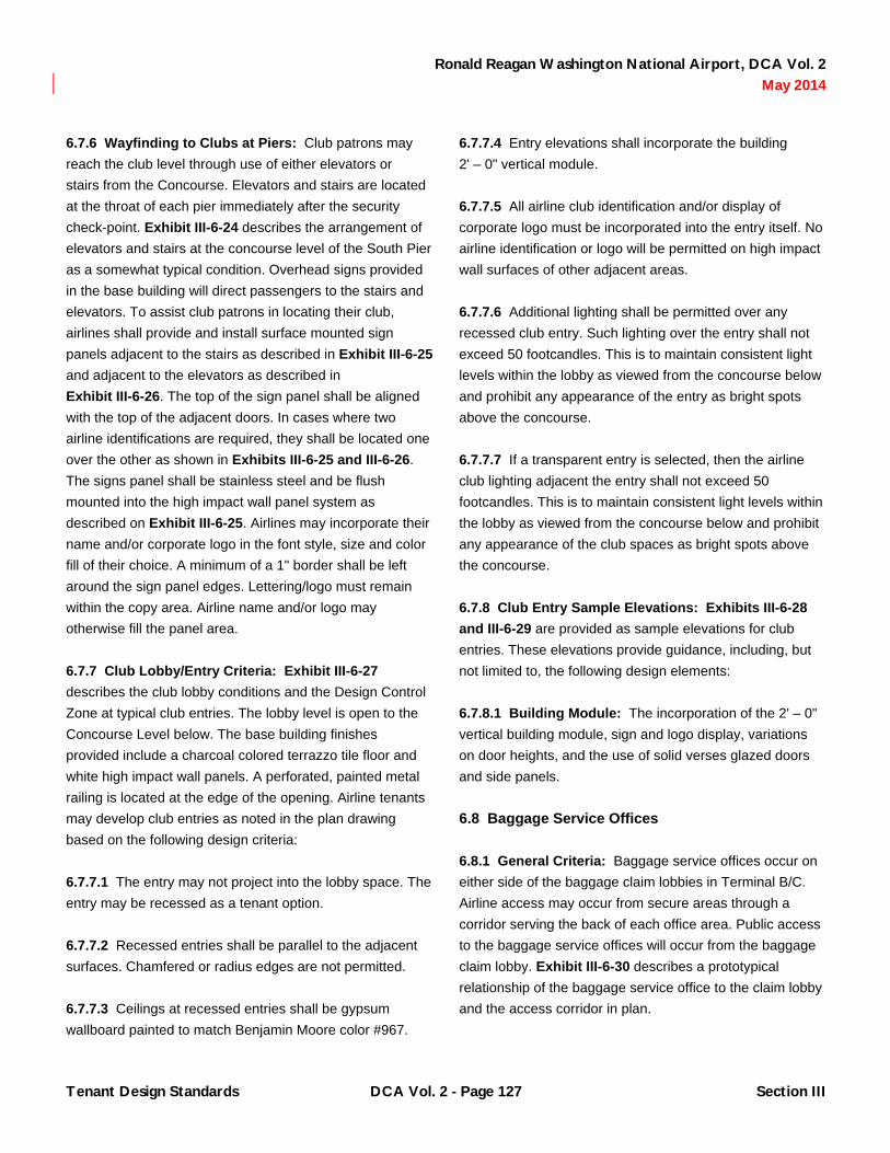
Ronald Reagan Washington National Airport, DCA Vol. 2 May 2014
6.7.6 Wayfinding to Clubs at Piers: Club patrons may reach the club level through use of either elevators or stairs from the Concourse. Elevators and stairs are located at the throat of each pier immediately after the security check-point. Exhibit III-6-24 describes the arrangement of elevators and stairs at the concourse level of the South Pier as a somewhat typical condition. Overhead signs provided in the base building will direct passengers to the stairs and elevators. To assist club patrons in locating their club, airlines shall provide and install surface mounted sign panels adjacent to the stairs as described in Exhibit III-6-25 and adjacent to the elevators as described in Exhibit III-6-26. The top of the sign panel shall be aligned with the top of the adjacent doors. In cases where two airline identifications are required, they shall be located one over the other as shown in Exhibits III-6-25 and III-6-26. The signs panel shall be stainless steel and be flush mounted into the high impact wall panel system as described on Exhibit III-6-25. Airlines may incorporate their name and/or corporate logo in the font style, size and color fill of their choice. A minimum of a 1" border shall be left around the sign panel edges. Lettering/logo must remain within the copy area. Airline name and/or logo may otherwise fill the panel area.
6.7.7 Club Lobby/Entry Criteria: Exhibit III-6-27 describes the club lobby conditions and the Design Control Zone at typical club entries. The lobby level is open to the Concourse Level below. The base building finishes provided include a charcoal colored terrazzo tile floor and white high impact wall panels. A perforated, painted metal railing is located at the edge of the opening. Airline tenants may develop club entries as noted in the plan drawing based on the following design criteria:
6.7.7.1 The entry may not project into the lobby space. The entry may be recessed as a tenant option.
6.7.7.2 Recessed entries shall be parallel to the adjacent surfaces. Chamfered or radius edges are not permitted.
6.7.7.3 Ceilings at recessed entries shall be gypsum wallboard painted to match Benjamin Moore color #967.
6.7.7.4 Entry elevations shall incorporate the building 2' – 0" vertical module.
6.7.7.5 All airline club identification and/or display of corporate logo must be incorporated into the entry itself. No airline identification or logo will be permitted on high impact wall surfaces of other adjacent areas.
6.7.7.6 Additional lighting shall be permitted over any recessed club entry. Such lighting over the entry shall not exceed 50 footcandles. This is to maintain consistent light levels within the lobby as viewed from the concourse below and prohibit any appearance of the entry as bright spots above the concourse.
6.7.7.7 If a transparent entry is selected, then the airline club lighting adjacent the entry shall not exceed 50 footcandles. This is to maintain consistent light levels within the lobby as viewed from the concourse below and prohibit any appearance of the club spaces as bright spots above the concourse.
6.7.8 Club Entry Sample Elevations: Exhibits III-6-28 and III-6-29 are provided as sample elevations for club entries. These elevations provide guidance, including, but not limited to, the following design elements:
6.7.8.1 Building Module: The incorporation of the 2' – 0" vertical building module, sign and logo display, variations on door heights, and the use of solid verses glazed doors and side panels.
6.8 Baggage Service Offices
6.8.1 General Criteria: Baggage service offices occur on either side of the baggage claim lobbies in Terminal B/C. Airline access may occur from secure areas through a corridor serving the back of each office area. Public access to the baggage service offices will occur from the baggage claim lobby. Exhibit III-6-30 describes a prototypical relationship of the baggage service office to the claim lobby and the access corridor in plan.
Tenant Design Standards DCA Vol. 2 - Page 127 Section III

Ronald Reagan Washington National Airport, DCA Vol. 2 May 2014
Airline Clubs, Wayfinding at Concourse Exhibit III-6-24
Tenant Design Standards DCA Vol. 2 - Page 128 Section III

Ronald Reagan Washington National Airport, DCA Vol. 2 May 2014
Airline Clubs, Signing at Stairs Exhibit III-6-25
Tenant Design Standards DCA Vol. 2 - Page 129 Section III

Ronald Reagan Washington National Airport, DCA Vol. 2 May 2014
Airline Clubs, Signing at Elevator Exhibit III-6-26
Tenant Design Standards DCA Vol. 2 - Page 130 Section III

Ronald Reagan Washington National Airport, DCA Vol. 2 May 2014
Airline Clubs, Lobby Plan Exhibit III-6-27
Tenant Design Standards DCA Vol. 2 - Page 131 Section III

Ronald Reagan Washington National Airport, DCA Vol. 2 May 2014
Airline Clubs, Typical Entrance Exhibit III-6-28
Tenant Design Standards DCA Vol. 2 - Page 132 Section III

Ronald Reagan Washington National Airport, DCA Vol. 2 May 2014
Airline Clubs, Typical Entrance Exhibit III-6-29
Tenant Design Standards DCA Vol. 2 - Page 133 Section III

Ronald Reagan Washington National Airport, DCA Vol. 2 May 2014
Baggage Service Office, Typical Plan Exhibit III-6-30
Tenant Design Standards DCA Vol. 2 - Page 134 Section III

Ronald Reagan Washington National Airport, DCA Vol. 2 May 2014
6.8.2 Design Control Zone: In an effort to provide aesthetic consistency in the claim lobby while allowing the tenants to address their individual needs relative to their use of this airline storage and public interaction office, the following criteria have been established for these storefronts and the baggage service office:
6.8.2.1 The storefront shall be centered on the architectural column line as indicated in Exhibit III-6-31. The entry to the baggage service office may not project into or be recessed back from the claim lobby.
6.8.2.2 Entry doors from public spaces shall swing in.
6.8.2.3 The division of storefronts between tenants shall occur at an 8' – 0" horizontal module as indicated in Exhibits III-6-31 and III-6-32.
6.8.2.4 If the tenant floor plan calls for a counter at which transactions with the public will occur, the front face of the counter may become the location of any directional change of the demising wall as indicated in Exhibit III-6-30.
6.8.2.5 Counters, backwalls, and opening in backwalls shall be developed by the tenant. If the counter, backwall and openings can be viewed by the public from the baggage claim lobby, the design of these elements shall comply with Chapter 5 and be subject to review and approval by the Authority.
6.8.2.6 If the interior of the baggage service office can be viewed by the public from the claim lobby, wall materials and colors, ceiling materials and color, floor materials and color and light fixtures shall comply with Chapter 5 and will be subject to design review and approval by the Authority.
6.8.2.7 If the interior of the baggage service office can be viewed by the public from the claim lobby, any permanent or temporary display fixtures intended for use on top of the counter for brochures or other airline literature, as well as any advertising, promotional materials, posters and other wall mounted material shall comply with Chapter 5 and be subject to review and approval by the Authority.
6.8.2.8 The baggage service office lighting shall not exceed 100 footcandles. This is to maintain consistent light levels within the baggage claim lobby and prohibit any appearance of these service offices as bright spots when viewed from the public claim area.
6.8.2.9 No window treatment is permitted in glazed storefront options.
6.8.3 Storefront Options: Baggage service office storefronts can be developed in 8' – 0" horizontal modules either as a transparent window wall, or as an opaque wall as desired by the tenant. Eight foot panel options are generally described in Exhibit III-6-31 and specifically described as Panel Options A through D on Exhibits III-6-32 through III-6-35. Design criteria include the following:
6.8.3.1 The tenant shall develop the storefront using the horizontal modules already established by the building architecture.
6.8.3.2 The window wall mullion system in glazed options shall be painted “Washington White” to correspond to other adjacent mullion systems existing in the claim area.
6.8.3.3 The tenant may develop any one of five options at the storefront as part of their tenant construction. These options have been developed to provide either a transparent or opaque storefront. The tenant shall review the most current construction document drawings and specification Section 08800 - Glazing for particulars on the varieties of glazing as referenced in this criteria.
6.8.3.4 All ceramic frit shall match the white color of the typical frit pattern used in the terminal.
6.8.3.5 The tenant may develop any combination of the options that their overall lease space will accommodate. Options include:
Tenant Design Standards DCA Vol. 2 - Page 135 Section III

Ronald Reagan Washington National Airport, DCA Vol. 2 May 2014
Baggage Service Office, Storefront Options Exhibit III-6-31
Tenant Design Standards DCA Vol. 2 - Page 136 Section III

Ronald Reagan Washington National Airport, DCA Vol. 2 May 2014
Baggage Service Office, Panel Option A Exhibit III-6-32
Tenant Design Standards DCA Vol. 2 - Page 137 Section III

Ronald Reagan Washington National Airport, DCA Vol. 2 May 2014
Baggage Service Office, Panel Option B Exhibit III-6-33
Tenant Design Standards DCA Vol. 2 - Page 138 Section III

Ronald Reagan Washington National Airport, DCA Vol. 2 May 2014
Baggage Service Office, Panel Option C Exhibit III-6-34
Tenant Design Standards DCA Vol. 2 - Page 139 Section III

Ronald Reagan Washington National Airport, DCA Vol. 2 May 2014
Baggage Service Office, Panel Option D Exhibit III-6-35
Tenant Design Standards DCA Vol. 2 - Page 140 Section III

Ronald Reagan Washington National Airport, DCA Vol. 2 May 2014
A. Panel Option A with clear glass, 50% frit glass or painted metal panel and a stainless steel base as described in Exhibit III-6-32.
B. Panel Option B with high impact wall panels and stainless steel base as described in Exhibit III-6-33.
C. Panel Option C with an 8' – 0" glazed or metal door with clear glass, 50% frit glass or painted metal panel sidelights and stainless steel base as described in Exhibit III-6-34.
D. Panel Option D with an 8' – 0" glazed or painted metal door with high impact wall side panels and stainless steel base as described in Exhibit III-6-35.
6.8.4 Signing/Graphics: The Authority will provide standard building door plaques at each public entry to a baggage service office. Airlines may display airline identification and/or corporate logo at offices either in the signband panel or adjacent to the door as indicated in Exhibits III-6-32 through III-6-35. Sign panels shall be flush mounted within the mullion system. Airline identification and/or logo may be displayed on as many signband panels as are contained in the tenant baggage service office frontage. The airline name may be in the font style, size and color of their choice. The airline name and logo shall be silk screened with an epoxy base painted onto a stainless #4 brushed finished panel. Lettering must remain within the copy area. Airline name and/or logo may otherwise fill the panel area. No additional signing, graphics and/or display of corporate logo will be permitted on the storefront or side panels. Signage may not be illuminated. Airline logos and corporate identities may also be displayed on the backwall of the office space. There are no restrictions to materials, typography, logo size or colors used within the panel dimensions indicated, however, signing and logos proposed for this area will be subject to review and approval by the Authority. Hours of operation display at baggage service office storefronts shall comply with Chapter 5.
6.9 Apron Operations Areas
6.9.1 General Criteria: The airlines may develop operations areas and offices on the apron level below each pier. Exterior walls at the apron consist of an insulated, metal panel system with structural steel tubes at 8' – 0" on center as shown in Exhibit III-6-36. Apron areas and office perimeter walls can be developed in 8' – 0" modules either as a solid wall or with overhead doors. Wall options include fully opaque or exterior windows as desired by the tenant. The 8' – 0" wall options use Exhibits III-6-37 and III-6-38 as a guideline. The overhead door options are in 4' – 0" segments as described in Exhibit III-6-38. Tenants may mix and match the overhead door/window/wall elevation options to meet the needs of their individual apron operation. Overhead and man-door locations shall be coordinated with adjacent apron features. Tenants shall review the most current constructions documents available from the Authority and/or inspect actual conditions to ensure that the design of apron level spaces is coordinated with anticipated or existing exterior apron conditions. Tenant construction shall be coordinated with anticipated or actual architectural details at these locations.
6.9.2 Elevation Options
6.9.2.1 The following criteria
have been established for the design of apron level spaces at the Piers:
A. The tenant shall develop the exterior wall using the horizontal modules already established by the building architecture.
B. Apron area façades shall be set back from the face of the hold room façade above as described on Exhibit III-6-36.
C. The window wall mullion system in glazed options shall be painted “Washington White” to match adjacent terminal construction.
Tenant Design Standards DCA Vol. 2 - Page 141 Section III

Ronald Reagan Washington National Airport, DCA Vol. 2 May 2014
Apron Level, Typical Elevation at Gate Bridge Exhibit III-6-36
Tenant Design Standards DCA Vol. 2 - Page 142 Section III

Ronald Reagan Washington National Airport, DCA Vol. 2 May 2014
Apron Operations, Elevation Options Exhibit III-6-37
Tenant Design Standards DCA Vol. 2 - Page 143 Section III

Ronald Reagan Washington National Airport, DCA Vol. 2 May 2014
Apron Operations, Elevation Options Exhibit III-6-38
Tenant Design Standards DCA Vol. 2 - Page 144 Section III

Ronald Reagan Washington National Airport, DCA Vol. 2 May 2014
D. Base condition to be an approximately 10½" high concrete curb to match standard terminal construction.
E. Solid panels to be corrugated metal panels or solid metal panels painted “Washington White”.
F. Doors to be painted “Washington White”.
G. The tenant may develop any combination of the wall/door options shown in Exhibits III-6-37 and III-6-38 that their overall lease space will accommodate. Door options include:
1) Single metal door aligned with either side of 8' – 0" module with adjacent metal panels.
2) Double metal door centered in 8' – 0" bay with adjacent metal panels.
3) Single metal door with glass side lights.
4) Single metal door center on 8' – 0" bay.
H. The tenant may develop any combination of the wall/window options shown in Exhibit III-6-37 that their overall lease space will accommodate. Window options include:
1) Single high window (2' – 0" option) with adjacent corrugated metal panels.
2) Two windows (4' – 0" option) with adjacent corrugated metal panels.
3) Three windows (6' – 0" option) with adjacent corrugated metal panels.
I. The tenant may incorporate an overhead metal door of the options shown in Exhibit III-6-38. Overhead door options include:
1) 8' – 0" door within an 8' – 0" building bay.
2) 16' – 0" door within two 8' – 0" building bays.
3) 12' – 0" door centered in two 8' – 0" building bays.
J. Additional overhead lighting if desired by the airline within the soffit Adjacent to airline apron level operations areas shall be provided by the tenant and shall match existing overhead lighting.
K. Tenant installed conduit at exterior operations areas shall be concealed.
6.9.2.2 Criteria for the design of apron spaces at the connector are under development.
6.9.3 Signing/Graphics: Airline signage desired at exterior apron personnel access doors to identify airline operation areas to airline employees shall be provided by the tenant. Tenant signs on apron doors shall match airport standard for base building room identity: Sign type T1. Signs are to be fabricated and installed following guidelines contained in the Terminal Construction Package, Volume 19, sheets G5.715 and 913. No additional signing, graphics and/or display of corporate logo will be permitted. Signage may not be illuminated. Display of airline logos, decals or other airline display will not be permitted on overhead doors or windows or in view of windows.
6.10 Hold Rooms
6.10.1 General Criteria: Airline hold rooms are located on each Pier and the Connector. The Authority will provide all seating within the designated hold room areas for all 35 aircraft gates. Hold room seating configurations have been prepared to identify seating locations and locate casework elements. Exhibit III-6-39 graphically represents the design criteria related to the hold room areas. The following criteria have been established for use of the hold room area with regard to seating arrangements, public circulation paths, egress, and queuing.
Tenant Design Standards DCA Vol. 2 - Page 145 Section III

Ronald Reagan Washington National Airport, DCA Vol. 2 May 2014
Hold Room Plan Seating Guidelines Exhibit III-6-39
Tenant Design Standards DCA Vol. 2 - Page 146 Section III

Ronald Reagan Washington National Airport, DCA Vol. 2 May 2014
6.10.1.1 Eames Tandem Sling Seating will be provided by the Authority as the standard for all hold rooms.
6.10.1.2 Trash Receptacles will be provided as described in Chapter 10. No tables or ash urns will be provided. Hold rooms are designated “no smoking” areas.
6.10.1.3 The number of seats is based on 50% of the passengers being seated. Passenger totals were based on an 80% aircraft load factor. This results in the following seat allocation by aircraft type:
A. B767 = 104 seats.
B. B757 = 78 seats.
C. MD80 = 60 seats.
6.10.1.4 The following minimum clear aisles will be maintained:
A. 3' – 6" between hold room seating.
B. 6' – 0" will be maintained around all gate counters.
C. 6' – 0" clear for all accessible routes to egress stairs.
6.10.1.5 Seating Arrangements: To the maximum extent possible, seating arrangements and podium locations occur so that adequate space is reserved to accommodate departing queues, simultaneous departures at closely adjacent gates, and sufficient gathering area, clearly designated as a meeter and greeter area by its association to the loading bridge gate and relationship to seating. If possible, queuing is perpendicular to the gate.
6.10.1.6 Seating Zones: Seating shall not occupy the zone immediately adjacent to the curtain wall. A minimum of 7' – 0" clear is recommended as shown.
6.10.1.7 Adjacent Seating Zones: Seating shall not occupy the zone immediately adjacent to the curtain wall. A minimum of 7' – 0" clear is recommended as shown.
6.10.1.8 Wall Phones and Seated Phones: Wall phones and seated phones will be provided by the Authority and are permanently located. Seating arrangements will accommodate these fixtures.
6.10.1.9 Seating Arrangement: Seating arrangement shall allow clear access to exits, commuter stairs, elevators, and life safety equipment.
6.10.1.10 Hold Room Seating: Hold room seating shall remain in the hold room area defined by the structural column line and demarcation created by the change in flooring material.
6.10.1.11 Passenger Queuing: Tenants shall be responsible for controlling passenger queuing at the gate counter so that it does not interfere with general circulation on the Piers or in the Connector. The tenant shall have available queue control devices to employ during any and all scheduled peaks and during unanticipated delays, when excessive queues may form. The queue is to be prevented from extending into adjacent circulation or public seating areas.
6.10.1.12 Gate Designations and MUFIDS: Gate designations and MUFID monitors will be provided at each gate as described in Exhibit III-6-39. The monitor at the loading bridge door may display destination information and serve as an ADA monitor to provide boarding information to the hearing impaired, as desired by the tenant. No other airline designation will be permitted on or adjacent to the door to the loading bridge.
6.10.1.13 Seating Arrangements: Seating will be arranged perpendicular to the curtainwall as shown in Exhibit III-6-39. Diagonal arrangements are prohibited.
Tenant Design Standards DCA Vol. 2 - Page 147 Section III

Ronald Reagan Washington National Airport, DCA Vol. 2 May 2014
6.10.2 Casework
6.10.2.1 Gate Counters: Stainless steel gate counter shells with solid core turret tops and stainless steel backscreens as described in Exhibits III-6-40 and III-6-41 will be provided by the Authority. There are counter options for two or three agent positions as required by the aircraft being served by the counter or operational requirements of the tenant. The options are as generally described in Exhibit III-6-42. Exhibit III-6-40 illustrates a composite elevation of a two position gate counter and backscreen.
6.10.2.2 Backscreens: A stainless steel backscreen behind the gate counters will be provided by the Authority as described in Exhibits III-6-43 through III-6-45 The backscreen will contain an Authority provided monitor to display gate number and flight information.
6.10.2.3 Ticket Lift/Ticket Service Podiums: Podiums will be provided by the Authority at each gate. Two types of podiums are available: ticket lift and ticket service podiums. Exhibit III-6-46 indicates preferred location of podium at the gate.
6.10.2.4 Luggage Sizing Boxes: Luggage sizing boxes, if desired by the tenant, shall be procured by the tenant. Exhibit III-6-46 generally describes the luggage sizing box standards. Construction documents that may be used by the tenant to procure luggage sizing boxes are available from the Authority. Luggage sizing boxes shall be located as indicated in Exhibit III-6-46.
6.10.2.5 Poster Brochure Racks: Poster Brochure Racks, if required by the tenant, shall comply with Exhibits III-6-47 through III-6-48. Construction documents that may be used by the tenant to procure additional poster brochure racks are available from the Authority.
6.10.3 Signing/Graphics: If required, numerical gate identification shall be displayed on the monitor located in the backscreen. Airline name may also be displayed in an airline provided panel of the dimensions indicated in Exhibit III-6-43. Airlines may incorporate their airline name
only on these panels. The panel shall be flush mounted. The airline name may be in the font style, size and color of their choice. The airline name shall be silk-screened on a stainless steel panel with #4 finish. Lettering must remain within the copy area. Airline name may otherwise fill the panel area. Only one airline name per sign panel will be allowed. No additional signing, graphics and/or display of corporate logo will be permitted on the counter, or sides or back panel of backscreen. Signage panel may not be illuminated. No signing or graphics of any kind will be permitted on any ticket lift or ticket service podium.
6.11 Baggage Claim Lobby
6.11.1 General Criteria: Except for airline identification at a baggage service office, no logo, signing or other graphics may be applied to any other surfaces, equipment or appurtenances within the claim area, including baggage claim devices, MUFID racks or monitors, or positive claim railing system if employed.
6.12 Other Airline Equipment/Fixtures
6.12.1 Advertising: Airlines may display airline promotional materials within the common use hold room areas only. Promotional materials shall be displayed in the Poster Brochure Rack as described in Exhibit III-6-47. All promotional materials will comply with Chapters 5 and 9. All promotional materials will be reviewed and approved by the Authority before airline display will be permitted.
Tenant Design Standards DCA Vol. 2 - Page 148 Section III

Ronald Reagan Washington National Airport, DCA Vol. 2 May 2014
Gate Counter Exhibit III-6-40
Tenant Design Standards DCA Vol. 2 - Page 149 Section III

Ronald Reagan Washington National Airport, DCA Vol. 2 May 2014
Gate Counter Exhibit III-6-41
Tenant Design Standards DCA Vol. 2 - Page 150 Section III

Ronald Reagan Washington National Airport, DCA Vol. 2 May 2014
Gate Counter, Plans Exhibit III-6-42
Tenant Design Standards DCA Vol. 2 - Page 151 Section III

Ronald Reagan Washington National Airport, DCA Vol. 2 May 2014
2-Position Backscreen Graphics Exhibit III-6-43
Tenant Design Standards DCA Vol. 2 - Page 152 Section III

Ronald Reagan Washington National Airport, DCA Vol. 2 May 2014
3-Position Backscreen Graphics Exhibit III-6-44
Tenant Design Standards DCA Vol. 2 - Page 153 Section III
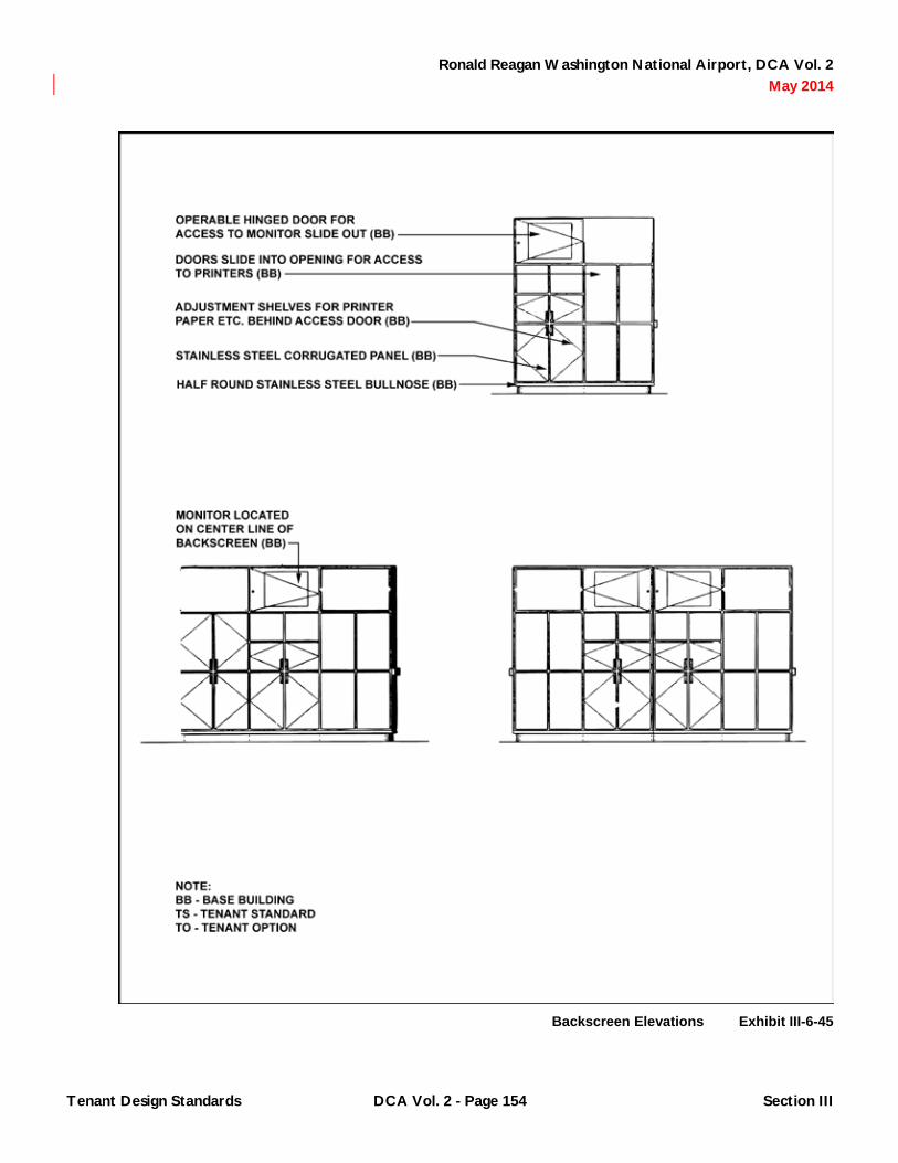
Ronald Reagan Washington National Airport, DCA Vol. 2 May 2014
Backscreen Elevations Exhibit III-6-45
Tenant Design Standards DCA Vol. 2 - Page 154 Section III

Ronald Reagan Washington National Airport, DCA Vol. 2 May 2014
Ticket Lift, Ticket Service Podium Exhibit III-6-46
Tenant Design Standards DCA Vol. 2 - Page 155 Section III
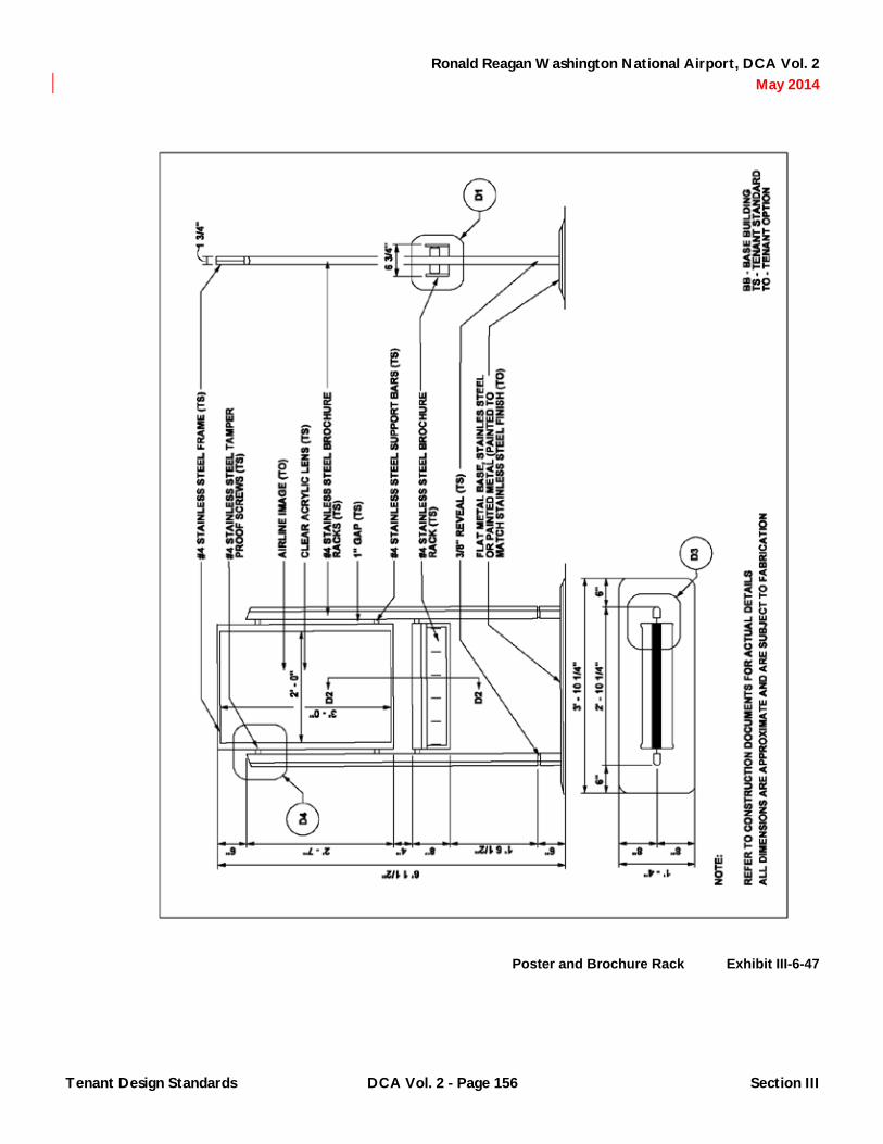
Ronald Reagan Washington National Airport, DCA Vol. 2 May 2014
Poster and Brochure Rack Exhibit III-6-47
Tenant Design Standards DCA Vol. 2 - Page 156 Section III

Ronald Reagan Washington National Airport, DCA Vol. 2 May 2014
Poster and Brochure Rack, Typical Details Exhibit III-6-48
Tenant Design Standards DCA Vol. 2 - Page 157 Section III

Ronald Reagan Washington National Airport, DCA Vol. 2 May 2014
6.12.2 Loading Bridges: Airlines may not attach or install any temporary or permanent decals, graphics, signing, advertising posters or other fixtures within the loading bridge, on either side of the door to the loading bridge, or the door itself or on the exterior of the bridge, bridge support or equipment attached thereto. Interior loading bridge finishes as described in Exhibit III-6-49 will be provided by the Authority. Tenants are not allowed to alter these base building elements, or any materials or fixtures that fall within them. This includes floors, walls, doors or ceiling surfaces.
6.12.3 Miscellaneous: Any loose equipment used by any air carrier or contract employee thereof within public areas in and around the Terminal will be reviewed and approved by the Authority. Such equipment includes, but is not limited to hand carts, “bellman” carts, tubs, and wheelchairs. Such mobile equipment shall have factory or manufacturer installed bumpers on all exposed edges and semi-inflatable tires to prevent damage to interior and exterior wall and floor finishes. Used equipment from other station locations is unacceptable. Airline tenants shall review selections of such equipment with the Authority prior to procurement and use.
6.12.3.1 Airside Dumpsters: Airside dumpsters are permitted at exterior apron locations. Locations shall be coordinated to maintain access to fire department connections, hydrants and fire lanes and fire exit routes from the Terminal complex. Airside dumpsters are recommended to be of one type, size and color. Tenants shall coordinate requirements with the Authority prior to installation.
6.12.4 Queue Control/Stanchions: Airline tenants shall employ queue control devices during any and all scheduled
peaks and unanticipated delays when excessive queues may form. Queue control in the Ticketing Level lobby shall follow the guidelines established in Exhibit III-6-14. Posts shall be located on the 4' – 0" terrazzo floor pattern module. Queue control devices shall comply with the criteria established in Chapter 5.
6.12.5 Other Casework: Individual airline tenants may have specific requirements for special custom casework to support their individual operations in connection with “ticket-less” travel or other similar programs. Such casework shall be coordinated with the Authority and developed in a design vocabulary consist with other casework. All such casework design and fabrication documents shall be reviewed and approved by the Authority prior to procurement.
6.12.6 Federally Regulated Sign Guidelines: Transportation Security Administration (TSA) and Federal Aviation Administration (FAA) signs will be provided by the Authority at casework locations including ticket counters, gate podiums, check-in podiums, and security check-points. Signs shall conform to the criteria and language established by the most current federal specifications.
Tenant Design Standards DCA Vol. 2 - Page 158 Section III

Ronald Reagan Washington National Airport, DCA Vol. 2 May 2014
Loading Bridge Exhibit III-6-49
Tenant Design Standards DCA Vol. 2 - Page 159 Section III

Ronald Reagan Washington National Airport, DCA Vol. 2 May 2014
(This Page Blank)
Tenant Design Standards DCA Vol. 2 - Page 160 Section III

Ronald Reagan Washington National Airport, DCA Vol. 2 May 2014
CHAPTER 7 Retail Tenant Design Standards
7.1 Locations Governed By Standards
7.1.1 General: Locations in Terminal B/C are dispersed throughout the main North/South Concourse and include free-standing kiosks located along the east side of the North/South Concourse and specific lease space locations within the Piers and Connector.
7.2 General Criteria/Prohibitions
7.2.1 Lighting: Retail tenants are encouraged to provide a “transparent” show window with merchandise highlighted in it instead of an opaque window display that blocks the view of the store interior. In addition, the rear wall of the Retail areas should be designated for feature displays.
7.2.1.1 Illumination levels for general lighting (non-display) shall comply with the following footcandle criteria in circulation areas:
A. Daytime and Nighttime: 10-30 footcandles horizontal at 3' – 0" above the finished floor.
7.2.1.2 Acceptable lighting equipment for general lighting in the Design Control Zone and the remaining Retail concession areas include the following:
A. Recessed linear fluorescent troffers or wallwashers (low-brightness or white louvers).
B. Pendent mounted linear fluorescent troffers (indirect or direct/indirect).
C. Recessed compact fluorescent downlight or wallwash fixtures with semi-specular low brightness reflectors.
7.2.1.3 Lighting Equipment selected by Retail tenants for general lighting will be subject to design review and approval by the Authority.
7.2.2 Merchandising: Materials used in merchandised displays within the Design Control Zone will conform to the criteria set forth in Chapter 5 except by special review and approval by the Authority.
7.2.2.1 Display Lighting shall be provided for the express purpose of highlighting merchandise in the display window. Acceptable lighting equipment for display lighting for merchandise areas include:
A. Recessed or track mounted incandescent adjustable fixtures for MR 16 or PAR 36 low voltage lamps with integral step down transformer and accessories.
B. Recessed or track mounted incandescent adjustable fixtures for PAR-20 or PAR-30 lamps and accessories.
7.2.2.2 Display Lighting Equipment selected by retail tenants for merchandise areas will be subject to design review and approval by the Authority. Recommended display illumination levels, including ambient light from external sources, should not exceed the following footcandle criteria on the merchandise:
A. Feature Displays (Daytime): 300-500 fc.
B. Feature Displays (Nighttime): 150-300 fc.
C. General Displays (Daytime and Nighttime): 30-100 fc.
7.2.2.3 Adjustable, Merchandise Lighting Equipment within the Design Control Zone and remaining retail areas must be positioned or shall have accessories to eliminate glare into public areas of the Terminal or retail circulation areas. Special attention to the use of mirrored surfaces in display will also be required to prevent reflected light and/or reflection of exposed bulbs. Use of decorative neon accent lighting within Retail displays may be approved by the Authority. Design review and approval will be required prior to fabrication and installation.
Tenant Design Standards DCA Vol. 2 - Page 161 Section III
Ronald Reagan Washington National Airport, DCA Vol. 2 May 2014
7.2.3 Music: Background music is permitted in tenant areas on either a temporary or permanent basis provided it is not audible in adjacent public or tenant areas.
7.3 North/South Concourse Storefronts
7.3.1 The Storefront Design for Terminal B/C shall follow the retail tenant submission requirements for the N/S Concourse. This requirement booklet is available through Concessions and Property Development. The requirements of this booklet supersede existing in place design requirements only and would take effect as existing tenant leases expire or when the tenant wishes to remodel their space. The Design Manual will take precedence over these booklets for everything except the Design Control Zone. The booklet will become an appendix in part or in total of the Design Manual for the Design Control Zone only as noted below:
Retail Tenant Submission Requirements – N/S Concourse – this booklet in its entirety becomes part of the Design Manual.
7.3.2 Backwalls/Sidewalls/Curtainwalls: Tenants along the North/South Concourse shall complete the interior partitions provided in the base building along the demising line of their lease premises. The portion of their demising wall that falls within the Design Control Zone shall have a painted gypsum wallboard finish. The tenant shall provide a ⅜" x ⅜" deep reveal joint to visually separate the Design Control Zone from the remainder of the demising wall. Within the Design Control Zone, the tenant shall provide a 6" high stainless steel base with #4 finish. The painted surfaces shall match Terminal Color P5. Tenants shall have the flexibility to select wall finishes of their own choosing within their lease space beyond the limit of the Design Control Zone. Wall finishes shall conform to the criteria set forth in Chapter 5.
7.3.3 Ceilings: Tenants along the North/South Concourse shall construct the interior ceilings of their lease premises. At a minimum, the portion of the ceiling that falls within the Design Control Zone shall have a painted gypsum
wallboard finish. The paint color shall match Terminal Color P5. Tenants shall have the flexibility to select ceiling finishes of their own choosing within their lease space beyond the limit of the Design Control Zone. Alternatively, tenants may elect to have an open ceiling beyond the Design Control Zone. The tenant shall be required to coordinate ceiling design with the base building structural, mechanical, fire protection and electrical systems and the installation of any tenant provided overhead grilles. No exposed conduit, tubing, raceways, conductors, transformers or other equipment will be permitted. Exposed ductwork will be permitted.
7.4 Pier Storefronts
7.4.1 The Storefront Design for Terminal B/C shall follow the retail tenant submission requirements for the Piers. This requirement booklet is available through Concessions and Property Development or can be found in electronic format on the CD. The requirements of this booklet supersede existing in place design requirements only and would take effect as existing tenant leases expire or when the tenant wishes to remodel their space. The Design Manual will take precedence over these booklets for everything except the Design Control Zone. The booklet will become an appendix in part or in total of the Design Manual for the Design Control Zone only as noted below:
Retail Tenant Submission Requirements – Piers and Connector - paragraphs 1 through 20.5 on pages 21 through 33 of this booklet shall be in addition to and not a replacement of the basic requirements of the Design Manual.
7.5 Connector Storefronts
7.5.1 The Storefront Design for Terminal B/C shall follow the retail tenant submission requirements for the Connector. This requirement booklet is available through Concessions and Property Development or can be found in electronic format on the CD. The requirements of this booklet supersede existing in place design requirements only and would take effect as existing tenant leases expire
Tenant Design Standards DCA Vol. 2 - Page 162 Section III

Ronald Reagan Washington National Airport, DCA Vol. 2 May 2014
or when the tenant wishes to remodel their space. The Design Manual will take precedence over these booklets for everything except the design control zone. The booklet will become an appendix in part or in total of the Design Manual for the design control zone only as noted below:
Retail Tenant Submission Requirements – Piers and Connector - paragraphs 1 through 20.5 on pages 21 through 33 of this booklet shall be in addition to and not a replacement of the basic requirements of the Design Manual.
7.6 Kiosks
7.6.1 Terminal B/C Kiosk Designs: The kiosk design for Terminal B/C shall follow the "Retail Tenant Submission Requirements – Airport Kiosk Design Criteria" for the main concourse and piers. This requirement booklet is available through Concessions and Property Development and can be found in electronic format on the 2007 Design Manual CD. The requirements of this booklet supersede existing in place design requirements only and would take effect as existing tenant leases expire or when the tenant wishes to remodel their space. The Design Manual will take precedence over these booklets for everything except the design control zone. The booklet will become appendices in part or in total of the Design Manual for the design control zone only as noted below:
Retail Tenant Submission Requirements – Airport Kiosk Design Criteria – page 3 through 23 of this booklet shall be in addition to and not a replacement of the basic requirements of the Design Manual. 7.6.2 Floors at Kiosks: The terrazzo floor material within the leased line may not be altered. Anti-Fatigue mats will be provided by the Authority. Tenants shall maintain and
replace these mats to match the original Authority provided standard. Tenants may not alter or affix signs or other display fixtures to the floor surface.
7.6.3 Backwalls/Sidewalls at Kiosks: The kiosk wall units are designed to include opaque storage areas, as well as transparent display units. A tack surface is provided on the interior of the upper cabinets. Tenants may not alter Authority provided casework or adjacent base building surfaces. Tenants may not alter or affix signs or other display fixtures to any exterior surfaces of any of the display units. Long stemmed aluminum push pins or adhesive-backed or Velcro strips are recommended for affixing items on signs to the tack surface provided. See Exhibits III-7-1 and III-7-2.
7.6.4 Kiosk Lighting: Ambient lighting at kiosks is provided by the overall terminal lighting. The retail light stanchions that are integral to the kiosk floor units also provide additional lighting and may be used to highlight items on the kiosks within the limits of the fixtures mechanisms. The kiosk floor and wall units themselves have standard interior lighting to illuminate items on display within glazed cases. No additional task lighting may be affixed to the kiosk units. No freestanding lighting will be permitted within the lease area.
Tenant Design Standards DCA Vol. 2 - Page 163 Section III

Ronald Reagan Washington National Airport, DCA Vol. 2 May 2014
Signboard Location Criteria Retail Kiosks (A) Exhibit III-7-1
Tenant Design Standards DCA Vol. 2 - Page 164 Section III

Ronald Reagan Washington National Airport, DCA Vol. 2 May 2014
Signboard Location Criteria Retail Kiosks (B) Exhibit III-7-2
Tenant Design Standards DCA Vol. 2 - Page 165 Section III

Ronald Reagan Washington National Airport, DCA Vol. 2 May 2014
Hand lettering is not acceptable. These small format signs shall be used for logo recognition, special pricing information or special feature information only. Cash registers/point-of-sale equipment must be contained within the kiosks point-of-sale units. Displays may not overhand the edge of the counters. Suction cup attachments are prohibited. Stacking of merchandise or kiosks cabinet top will not be permitted.
7.6.5 Kiosk Furniture: Seating for kiosk attendants shall be provided by the Tenant. Acceptable seating is limited to a stool with an adjustable height range from 20" to 50" as manufactured by:
7.6.5.1 Herman Miller, Style “Equa” fabric to be determined.
7.6.6 Queue Stanchions at Kiosks: Use of queuing stanchions at kiosks is not recommended, however, if customer queues at any kiosk location begin to interfere with general circulation along the North/South Concourse, then the criteria established in Chapter 5 shall apply.
7.7 Retail Merchandising Units (RMU)
7.7.1 RMU Floors: The terrazzo tile floor material around the RMU may not be altered. Mats may not be located around the RMU. Tenants may not affix or place signs, advertising, furniture or display merchandising around the RMU.
7.7.2 RMU Surfaces: The RMUs are designed to include ample storage areas, as well as maximum display areas. Tenants may not alter the Authority provided casework or adjacent base building surfaces. Tenants may not alter or affix signs or other display fixtures to any exterior surfaces of any part of the RMU structure or cabinetry.
7.7.3 RMU Lighting: Ambient lighting at kiosks is provided by the overall terminal lighting. The RMU also incorporates additional lighting in the form of adjustable incandescent downlights that may be used to highlight displays and merchandise on the RMU. The RMU also
includes a lighted signbox that illuminates a tenant sign panel and casts ambient light to the surfaces below and to canopy panels above. No additional lighting may be affixed or located on the RMU. No additional freestanding lighting will be permitted adjacent to the RMU in any location.
7.7.4 RMU Signing/Graphics: Each RMU tenant will have one internally illuminated two-sided signbox. The dimensions of this sign are limited to the dimensions of the signbox itself. Tenant signbox inserts shall be executed in clear acrylic with silk-screened white lettering and logo graphics. This signbox is required and is to be used to communicate the corporate identity/logo. Letter style and size may be selected by the tenant. Tenants shall be required to submit graphic representations of signbox inserts for Design Review and Approval prior to submitting camera ready art for fabrication. Corporate identification/logo signing shall be limited to the insert in the signbox provided as part of the RMU casework. No other fixed or movable tenant signing shall be permitted on the RMU unit.
7.7.5 RMU Merchandising: Materials, signing and graphics used in merchandise displays in or on the RMU unit shall conform to the criteria set forth in Chapter 5 except by special review and approval. Displays and/or display fixtures intended for use on the kiosk counter top, including, but not limited to, counter stands, literature holders, price tag holders and easels shall be clear acrylic. Display and display fixtures shall be limited to a maximum height of 18 inches below the lighted underside of the signbox. Suction cups, tape, clips, hangars or any other adhesives may not be used on the RMU. All displays must rest, via gravity, on the Authority provided shelving and display surfaces. No display will be permitted on the floor adjacent to the RMU. Displays may not overhang the counter or shelf edges. Signing associated with display fixtures is limited to small labels, easel backed, or of metallic finish. Sign dimensions are a maximum of 5" x 7" horizontally oriented. Copy minimum of ⅝" letters in black, silk-screened or applied vinyl. Typography will be professionally prepared. Hand lettering is not acceptable. These small format signs shall be used for logo recognition,
Tenant Design Standards DCA Vol. 2 - Page 166 Section III

Ronald Reagan Washington National Airport, DCA Vol. 2 May 2014
special pricing information or special feature information only. Cash registers shall be located on one of the two pull out shelves located on either end of the RMU. They may not be located on the perforated metal shelving. Cash registers must be stored on the RMU counter surface after hours.
7.7.6 RMU Furniture: One seating stool will be provided to the tenant by the Authority. This stool must be fastened to the RMU after hours via a security cable provided with the RMU. Nothing may be attached or displayed upon the stool.
7.7.7 Closure Systems: After hours of operation, the RMU must be secured in the Authority provided cloth enclosure. This enclosure will be stored within the unit during hours of operation. The assembly of this enclosure requires that the side shelving be removed and stored. The cash drawers must also be placed in the closed position. Locks will be provided by the Authority.
Tenant Design Standards DCA Vol. 2 - Page 167 Section III

Ronald Reagan Washington National Airport, DCA Vol. 2 May 2014
(This Page Blank)
Tenant Design Standards DCA Vol. 2 - Page 168 Section III

Ronald Reagan Washington National Airport, DCA Vol. 2 May 2014
CHAPTER 8 Food-and-Beverage Tenant Design Standards
8.1 Locations Governed By Standards
8.1.1 General: Food-and-beverage tenant locations are generally identified on Exhibit III-4-1. Locations in Terminal B/C include spaces dispersed along the main North/South Concourse, specific locations along the Piers and in the Connector. Food court areas, adjacent to public seating areas, occur at the ends of each Pier. Food-and-beverage Kiosks, also known as Public Square Kiosks, anchor either end of the main North/South Concourse. These areas, in which seating is provided have been developed as “pause-points” in the North/South Concourse. The two-level Destination Restaurant is located at the entrance to the Center Pier. A main central lounge, also known as the Ticket Level Café, is located on the Ticketing Level overlooking the North/South Concourse.
8.2 General Criteria/Prohibitions
8.2.1 Lighting: Food-and-beverage tenants in enclosed lease areas are encouraged to provide a “transparent” show window with dining or food service areas highlighted. Opaque window displays that block the views of café or restaurant interiors are discouraged.
8.2.1.1 Illumination levels for Food-and-beverage establishments shall comply with the following footcandle criteria by area during daytime and nighttime hours:
A. Circulation Areas: 10-30 fc horizontal at 3' – 0" above the finished floor.
B. Dining Areas: 5-10 fc.
C. Cashier: 20-50 fc.
8.2.1.2 Display lighting shall be provided for the express purpose of highlighting merchandise and food at food service or food display areas. Acceptable lighting
equipment for display lighting for merchandise areas include:
A. Recessed or track mounted incandescent adjustable fixtures for MR 16 or PAR 36 low voltage lamps with integral step down transformer and accessories.
B. Recessed or track mounted incandescent adjustable fixtures for PAR-20 or PAR-30 lamps and accessories.
8.2.1.3 Recommended illumination levels for Food-and-beverage displays include the following footcandle criteria by area during daytime and nighttime hours:
A. Food Service: 25-75 fc.
B. Food Selection Areas: 25-75 fc.
8.2.1.4 Adjustable merchandise lighting equipment within the Design Control Zone and remaining Food-and-beverage areas must be positioned or shall have accessories to eliminate glare into public areas of the Terminal or food-and-beverage circulation areas. Special attention to the use of mirrored surfaces will also be required to prevent reflected light and/or reflection of exposed bulbs. Use of decorative neon accent lighting within food-and-beverage displays may be approved by the Authority. Design review and approval will be required prior to fabrication and installation. All lighting equipment selected by Food-and-beverage tenants shall be subject to design review and approval.
8.2.2 Signing/Graphics Inside Lease Line
8.2.2.1 Menu boards shall be used to provide menu and price information for restaurant, café and fast food establishments. Menu boards shall be specifically designed for use in the Terminal. Food-and-beverage boards provided to tenants by distributors, vendor product advertising and photographs of food are not acceptable.
Tenant Design Standards DCA Vol. 2 - Page 169 Section III

Ronald Reagan Washington National Airport, DCA Vol. 2 May 2014
Tenant corporate standard graphic programs for menu boards, if reviewed and approved by the Authority, may be acceptable for installation in Terminal B/C. Glass front self-supporting display cases edged in aluminum or stainless steel with slide-in or other changeable digit systems that allow items and prices to be changed independently are recommended for main entrances to cafes. Size, mounting height and method of attachment will be reviewed and approved by the Authority. Backlit or illuminated menu boards are recommended at all locations. Materials shall be non-glare and illumination must not interfere with readability. Accent lighting shall be concealed. Other menu board options may be acceptable at fast food locations in the Food Court areas on the Piers or at other locations. Menu board materials, size, placement, means of attachment and proposed accent lighting will be reviewed and approved by the Authority. Menu boards may be located above food service counters and/or at a backwall of the food service preparation or service area. Menu boards located above food service counters shall be located as shown in the Exhibits provided in this Chapter by terminal area.
8.2.2.2 Miscellaneous signs, including, but not limited to liquor license, occupancy posting, manager-on-duty, and employee of the month shall comply with Chapter 5.
8.2.3 Fixtures/Millwork/Furniture/Equipment: Food-and-beverage areas shall maintain a “clutter-free” appearance of spaces that are visible to the general public. To the maximum extent possible dispensers for cups, straws, stirrers, cup covers, napkins, utensils and/or condiments shall be integrated into the design of casework for counters or wait stations. No used fixtures, furnishings or equipment are permitted if they can be viewed from public areas.
8.2.3.1 To provide a cohesive appearance of fast food service areas within the Terminal, food service counters and tray rails shall be developed with a uniform appearance. Counters shall be clad with ceramic enamel panels in 2' – 0" horizontal modules and have black rubber bases and stainless steel counter tops with a continuous
stainless steel bullnose. The ceramic enamel fascia panel may be executed in colors and motifs selected by the tenants. The counter top beyond the continuous stainless steel bullnose may be executed in colors and materials selected by the tenants. Colors and materials shall comply with the standards described in Chapter 5. Counters may be 32", 34" or 42" high. A maximum of 54" is permitted inclusive of food displays areas or sneeze guards which may be integrated into the counter design. A continuous stainless steel bullnose shall be incorporated at the vertical locations indicated.
8.2.3.2 Where tray rails are incorporated into the counter frontage, tray rails shall be fabricated entirely of stainless steel. Tray rail supports shall be located on the 2 foot horizontal module.
8.2.3.3 Demising wall shall be completed by the tenant between two or more adjacent food service counter areas. Demising walls shall be no higher than 54 inches at food court locations in the Piers or on the Connector to encourage visibility and to reinforce the Food Court atmosphere.
8.2.3.4 Sneeze guards and food display cases shall be constructed of clear glass or acrylic materials free from patterns, decals or applied colors. Frames shall be stainless steel, chrome or clear anodized aluminum. If contiguous with the food service counter frontage and terminating at a demising wall, sneeze guards and display cases shall be a maximum of 4' – 6" high.
8.2.3.5 Cases for the display of souvenirs and/or related retail merchandise, including, but not limited to T-shirts, cups, and packaged foods, shall comply with Chapter 5.
8.2.4 Music: Background music is permitted in tenant areas on either a temporary or permanent basis provided it is not audible in adjacent public or tenant areas.
8.2.5 Queue Control/Stanchions: tenants shall be responsible for controlling individual queues within or immediately adjacent to their lease premise so that the
Tenant Design Standards DCA Vol. 2 - Page 170 Section III

Ronald Reagan Washington National Airport, DCA Vol. 2 May 2014
customer queue does not interfere with either internal circulation or circulation through public areas. The food-and-beverage developer shall have available queue control devices to provide to food-and-beverage tenants for their use when excessive queues may form. At Food Court areas located at the end of each Pier, or fast food areas that may be developed in the Connector, design shall maintain a minimum setback from the lease line in front of any counter area where queuing may occur. The setback dimension varies by location.
8.2.6 Signing/Graphics Outside of Lease Area: Food-and-beverage locations along the North/South Concourse of Terminal B/C may use for advertising display one free-standing, non-illuminated, double-sided advertising stanchion as provided by the Authority and described in Chapter 4. The stanchion is part of the design vocabulary of other base building fixtures and casework and shall be floor mounted at pre-determined locations so that it does not present a hazard to passengers and visitors as they circulate through the concourse. They will always occur in the same fixed location so that they can be readily identified by the visually impaired. Graphic materials for installation in the ad stanchions shall comply with Chapters 5 and 9. Graphic materials will be approved by the Authority prior to installation in the ad stanchion unit.
8.3 North/South Concourse Storefronts
8.3.1 The Storefront Design for Terminal B/C shall follow the retail tenant submission requirements for the N/S Concourse. This requirement booklet is available through Concessions and Property Development or can be found in electronic format on the 2005 Design Manual CD. The requirements of this booklet supersede existing in place design requirements only and would take effect as existing tenant leases expire or when the tenant wishes to remodel their space. The Design Manual will take precedence over these booklets for everything except the Design Control Zone. The booklet will become an appendix in part or in total of the Design Manual for the Design Control Zone only as noted below:
Retail Tenant Submission Requirements – N/S Concourse – this booklet in its entirety becomes part of the Design Manual.
8.3.2 Floors: A terrazzo border is provided in the Design Control Zone. Tenants shall not cover or otherwise alter this border. Tenants shall have the flexibility to select floor finishes of their own choosing within their lease space beyond the limit of the Design Control Zone.
8.3.3 Backwalls/Sidewalls/Curtainwalls: Tenants along the North/South Concourse shall complete the interior partitions along the demising line of their lease premises. The portion of their demising wall that falls within the Design Control Zone shall have a painted gypsum wallboard finish. The paint color shall match Terminal Color P5. The tenant shall provide a ⅜" x ⅜" deep reveal joint to visually separate the Design Control Zone from the remainder of the demising wall. If counters occur at the edge of the Design Control Zone, the reveal shall terminate at the counter. The tenant shall provide a 6" high stainless steel base with #4 finish. This stainless steel base shall be contiguous with the 6" rubber base provided for any food service counter that may terminate at the demising wall. Tenants shall have the flexibility to select wall finishes of their own choosing within their lease space beyond the limit of the Design Control Zone. Wall finishes shall conform to the criteria set forth in Chapter 5.
8.3.4 Ceilings: Tenants along the North/South Concourse shall construct the interior ceilings of their lease premises. At a minimum, the portion of the ceiling that falls within the Design Control Zone shall have a painted gypsum wallboard finish. The paint color shall match Terminal Color P5. If menu boards are ceiling mounted over a counter located at the edge of the Design Counter Zone, then the Design Control Zone of the ceiling shall extend to the face of the menu board. Tenants shall have the flexibility to select ceiling finishes of their own choosing within their lease space beyond the limit of the Design Control Zone. Alternatively, tenants may elect to have an open ceiling beyond the Design Control Zone. The tenant shall be required to coordinate ceiling design with the base building
Tenant Design Standards DCA Vol. 2 - Page 171 Section III

Ronald Reagan Washington National Airport, DCA Vol. 2 May 2014
structural, mechanical, fire protection and electrical systems and the installation of any tenant provided overhead grilles. No exposed conduit, tubing, raceways, conductors, transformers or other equipment is permitted. Exposed ductwork will be permitted if integrated in an architectural manner. Exposed ductwork shall be designed to be integrated and compatible with the interior design theme and intent. Exposed duct work shall be reviewed and approved by the Authority.
8.3.5 Storefront Signing/Graphics: Tenants shall be able to freely display and market within the lease areas and within the Design Control Zone within the material limitation of the criteria set forth in Chapter 5. Sign bands and blade signs shall be incorporated into the storefront using the prototypical details contained in Chapter 5.
8.3.5.1 Signband: Each tenant shall have at least one internally-illuminated signband. This signband shall be located over entry portals to individual Food-and-beverage areas or above lease space if totally unenclosed. The signband shall be developed in the 8 foot horizontal storefront module. Signband fascia shall be as described in Chapter 5. The signband shall be used to communicate corporate identification. Tenants shall be free to select lettering style and size in execution of the signband fascia. Tenants whose lease space spans an entire bay (column line to column line) may use up to three sign bands in any horizontal arrangement. Tenants whose lease frontage spans this space shall provide blank aluminum panels, finished to match adjacent signband fascias, for insertion in the remaining frames.
8.3.5.2 Each tenant may elect to install at least one internally illuminated double-sided blade sign for Food-and-beverage locations within the North/South Concourse, up to a maximum of two blade signs for tenants who occupy an entire bay. Blade signs shall be located on any of the four interior vertical storefront elements. The dimensions of these blade signs are fixed, as is the frame, position, and mounting. Within the blade frame tenants shall have freedom to use color, food-and-beverage identity and logos. Tenants shall select colors to provide sufficient
contrast to ensure that logos are clear and legible. Blade signs are as described in Chapter 4 and Exhibit III-4-3. Blade sign inserts shall be as described in Chapter 5. Design review and approval by the Authority of graphic representations of signband fascias and blade sign logo inserts will be required prior to fabrication and installation.
8.4 Pier Storefronts
8.4.1 The Storefront Design for Terminal B/C shall follow the retail tenant submission requirements for the piers. This requirement booklet is available through Concessions and Property Development. The requirements of this booklet supersede existing in place design requirements only and would take effect as existing tenant leases expire or when the tenant wishes to remodel their space. The Design Manual will take precedence over these booklets for everything except the Design Control Zone. The booklet will become an appendix in part or in total of the Design Manual for the Design Control Zone only as noted below:
Retail Tenant Submission Requirements – Piers and Connector - paragraph 1 through 20.5 on pages 21 through 33 of this booklet shall be in addition to and not a replacement of the basic requirements of the Design Manual.
8.5 Connector Storefronts
8.5.1 The Storefront Design for Terminal B/C shall follow the retail tenant submission requirements for the connector. This requirement booklet is available through Concessions and Property Development. The requirements of this booklet supersede existing in place design requirements only and would take effect as existing tenant leases expire or when the tenant wishes to remodel their space. The Design Manual will take precedence over these booklets for everything except the Design Control Zone. The booklet will become an appendix in part or in total of the Design Manual for the Design Control Zone only as noted below:
Retail Tenant Submission Requirements – Piers and Connector - paragraphs 1 through 20.5 on pages 21
Tenant Design Standards DCA Vol. 2 - Page 172 Section III

Ronald Reagan Washington National Airport, DCA Vol. 2 May 2014
through 33 of this booklet shall be in addition to and not a replacement of the basic requirements of the Design Manual.
8.6 Public Square Kiosks
8.6.1 Exception and Additions: Design Control Zones for Public Square Kiosks are as shown on Exhibit III-8-1.
8.6.2 Floors at Public Square Kiosks: The terrazzo floor material within the lease line may not be altered. Anti-fatigue mats suitable for installations where Food-and-beverage preparation and service will occur will be provided by the Authority. Tenants may not alter or affix signs or other display fixtures to the floor surface.
8.6.3 Backwalls/Sidewalls at Public Square Kiosk: An alcove has been provided at each Public Square Kiosk as shown in Exhibits III-8-2 and III-8-3. A portion of this alcove includes Authority provided casework, signband and security grilles as described in Chapter 6. The Design Control Zone for this alcove is shown on Exhibit III-8-3. The remaining wall surfaces, counter areas and under counter areas shall be developed by the tenant. The area may be developed as a combination food preparation and/or storage area, food/merchandising display, and menu board display. Tenants are encouraged to use materials that will complement the adjacent kiosk vocabulary and to acknowledge the horizontal module established by the signband over the alcove and the vertical module established by the adjacent high impact wall panels. The location of all fixed equipment, shelving, menu boards or associated fixtures shall allow free operation of the overhead grille which will secure the area during non-operational hours. Suggested options for this area are described in Exhibit III-8-4. Tenant fit-out shall conform to the criteria set forth in Chapter 5. Tenants may not alter Authority provided casework or adjacent base building wall surfaces.
8.6.4 Public Square Kiosk Lighting: Ambient lighting at Public Square Kiosks is provided by the overall terminal lighting. The Retail light stanchions that are integral to the units also provide additional lighting and may be used to highlight items on the kiosks within the limits of the fixtures mechanisms. The glazed kiosk floor units themselves have standard interior lighting to illuminate items on display. Lighting is also provided within the alcove over the central counter area. No additional task lighting may be affixed to the Public Square Kiosk units. No freestanding lighting will be permitted within the lease area. Additional lighting incorporated into the alcove area may be permitted if desired by the tenant for highlighting displays or merchandise. Any such additional lighting shall be reviewed and approved by the Authority.
8.6.5 Public Square Kiosk Signing/Graphics: Each Public Square Kiosk shall have one internally illuminated double-sided blade sign and an illuminated signband. The blade sign and signband are as indicated in Exhibit III-8-2. The dimensions of this signband are limited to the dimensions of the alcove. This signband and blade sign are required and are to be used to communicate corporate identification and logo as indicated in Exhibit III-8-5. Letter style and size may be selected by the tenant. The dimensions of the blade signs are limited to the vertical module, as are the frame, position, and mounting. Within the blade frame, tenants shall have freedom to use color, Retail identity and logos. Tenants shall select colors to provide sufficient contrast to ensure that logos are clear and legible. Blade sign inserts shall be as described in Chapter 5. Tenants may not affix temporary or permanent signs to any exterior surfaces of any of the display units or to the overhead grille. Tenants shall be required to submit graphic representations of signband fascia and blade sign inserts for design review and approval prior to submitting camera-ready art to the Authority for insert fabrication.
Tenant Design Standards DCA Vol. 2 - Page 173 Section III

Ronald Reagan Washington National Airport, DCA Vol. 2 May 2014
Design Control Zone Public Square Kiosks Exhibit III-8-1
Tenant Design Standards DCA Vol. 2 - Page 174 Section III

Ronald Reagan Washington National Airport, DCA Vol. 2 May 2014
Backwall and Alcove Public Square Kiosks Exhibit III-8-2
Tenant Design Standards DCA Vol. 2 - Page 175 Section III

Ronald Reagan Washington National Airport, DCA Vol. 2 May 2014
Design Control Zone Public Square Kiosks Exhibit III-8-3
Tenant Design Standards DCA Vol. 2 - Page 176 Section III

Ronald Reagan Washington National Airport, DCA Vol. 2 May 2014
Backwall and Alcove Options, Public Square Kiosks Exhibit III-8-4
Tenant Design Standards DCA Vol. 2 - Page 177 Section III

Ronald Reagan Washington National Airport, DCA Vol. 2 May 2014
Public Square Kiosks Signband Detail Exhibit III-8-5
Tenant Design Standards DCA Vol. 2 - Page 178 Section III

Ronald Reagan Washington National Airport, DCA Vol. 2 May 2014
Menu boards shall be contained within the back alcove area. Free-standing non-illuminated menu boards may be permitted within close proximity of the kiosks for viewing from the customers queue areas. Such menu boards shall be fabricated in a vocabulary similar to the advertising stanchions provided by the Authority at other locations throughout the terminal. Such menu boards shall remain within the Design Control Zone and shall not impede movement to the kiosk point-of-sale units or to the seating areas. Proposed menu board designs shall be reviewed and approved by the Authority prior to fabrication and use.
8.6.6 Public Square Kiosk Merchandising: Materials, signing and graphics used in merchandise displays within the Design Control Zone shall conform to the criteria set forth in Chapter 5 except by special review and approval. Any merchandising or display areas developed in the alcove area shall be professionally developed and maintained. Display fixtures intended for use on top of kiosk units, including, but not limited to, counter stands, literature holders, price tag holders, and easels shall be clear acrylic. Display fixtures shall be limited to a height of 18" and of an overall size which will allow the display fixtures to be locked into the kiosk casework when the kiosk is closed. All displays must be removed from counter tops when the kiosk is closed. Suction cup attachments are prohibited. Signing associated with display fixtures is limited to small easel backed labels of metallic finish. Sign dimensions are a maximum of 5" x 7" horizontally oriented. Copy minimum is ⅝" letters in black silk-screened or applied vinyl. Typography will be professionally prepared. Hand lettering is not acceptable. These small format signs are for logo recognition, special pricing information or special feature information only. Cash registers/point-of-sale equipment must be contained within the kiosks point-of-sale unit(s). Displays may not overhang the edge of the counters. Suction cup attachments are prohibited. Stacking of merchandise on kiosk cabinet tops will not be permitted.
8.6.7 Public Square Kiosk Furniture
8.6.7.1 Seating for Public Square Kiosk Attendants: Seating for Public Square Kiosk attendants shall be
provided by the tenant. Acceptable seating is limited to a stool with an adjustable height range from 20" to 50" as manufactured by:
A. Herman Miller, Style “Equa,” fabric to be determined.
8.6.7.2 Arrangement of Authority provided seating, tables and accessories shall be as shown in Exhibit III-8-6.
8.6.8 Queue Stanchions at Public Square Kiosks: Use of queuing stanchions at Public Square Kiosks is not recommended. Queues shall be confined to areas immediately adjacent to the point-of-sale units. However, if customer queues begin to interfere with circulation to seating areas within the Public Square Kiosk area, then the criteria established in Chapter 5 shall apply. Public Square Kiosk tenants shall coordinate location of queue stanchions with the Authority so that they do not interfere with seating and table arrangements.
8.7 Ticket Level Café
8.7.1 Design Control Zones: There are three distinct control zones for the Ticket Level Café:
8.7.1.1 Seating Area as shown in Exhibit III-8-7.
8.7.1.2 Back Bar area as shown in Exhibit III-8-8.
8.7.1.3 Back Bar Elevation
8.7.2 Ticket Level Café Seating Area: The seating area shown in Exhibit III-8-7 extends throughout the area from the Authority provided balustrade to the Authority provided front bar casework. Tenants shall maintain the seating and table arrangements shown in order to ensure proper circulation through the area. The balustrade is provided as part of the Architectural Enhancement Program (AEP) described in Chapter 1 and tenants may not alter or affix any items to this balustrade.
Tenant Design Standards DCA Vol. 2 - Page 179 Section III

Ronald Reagan Washington National Airport, DCA Vol. 2 May 2014
FF and E Arrangement Public Square Kiosks Exhibit III-8-6
Tenant Design Standards DCA Vol. 2 - Page 180 Section III

Ronald Reagan Washington National Airport, DCA Vol. 2 May 2014
Design Control Zone, Ticket Level Cafe Exhibit III-8-7
Tenant Design Standards DCA Vol. 2 - Page 181 Section III

Ronald Reagan Washington National Airport, DCA Vol. 2 May 2014
Design Control Zone, Back Bar Area Exhibit III-8-8
Tenant Design Standards DCA Vol. 2 - Page 182 Section III

Ronald Reagan Washington National Airport, DCA Vol. 2 May 2014
With the exception of the tenant-provided work area behind the counter, tenants may not attach or affix other accessories or equipment to the front bar counter, light fixtures or overhead grilles. Any non-fixed items must be located so as to permit free operation of the overhead closure grilles. Any additional casework, millwork or accessories deemed necessary by the tenant for use in this area shall be reviewed and approved by the Authority and shall comply with the criteria set forth in Chapters 5 and 8.2. Additional lighting in this front bar counter is not permitted.
8.7.3 Ticket Level Back Bar Walls/Counter/Sidewalls: The back bar area is created by the elevator core and back bar enclosure. This zone is shown on Exhibit III-8-8 and is finished as described in Chapter 4. The tenant shall maintain the doors, floor finishes and wall finishes provided. The tenant may construct the back bar counter.
8.7.4 Ticket Level Back Bar Walls: The tenant shall develop their back bar area within the horizontal and vertical limits. The tenant is encouraged to develop display, merchandising, and menu boards in this area in a manner that complements the vocabulary established by the front counter casework, light stanchions and the corrugated stainless elevator core and back bar enclosure. Tenants are encouraged to develop arrangements that acknowledge the vertical and horizontal modules established by the base building. Counter, displays, equipment layout and other proposed fixtures and accessories proposed for construction or installation in this area shall be reviewed and approved by the Authority and shall comply with the criteria set forth in Chapters 5 and 8.2.
8.7.5 Ticket Level Café Signing/Graphics: Signing and graphics materials may be displayed within the Authority provided sign stanchions at either end of the bar. In addition, the tenant shall be able to freely display and market within the area immediately above the back bar counter. No other signing or graphic displays will be permitted. If desired, the tenant may use one advertising stanchion at a location on the North/South Concourse to advertise the bar. The location will be reviewed and
approved by the Authority. Ad stanchion use is subject to the availability of stanchions at the time of tenant request. All signing and graphics shall comply with the criteria set forth in Chapter 5. Signing and graphics within the Ticket Level Café Sign Stanchion and/or ad stanchion shall comply with the criteria set forth in Chapter 9.
8.7.6 Ticket Level Café Display/Merchandising/ Equipment: The back bar area display area shall be professionally developed and maintained. Additional lighting may be incorporated into the back bar display or under counter area. Additional lighting shall be adjustable and shall have accessories to eliminate glare into the adjacent seating area at the bar. If mirrored surfaces are used, care shall be taken to prevent reflected light and/or reflection of exposed bulbs. Use of decorative neon accent lighting will not be permitted at the Ticket Level Café. The tenant shall periodically inventory and review the display area. Worn or damaged displays items shall be replaced. No used fixtures or equipment is permitted if it can be viewed from public areas.
8.7.7 Ticket Level Café Storage Areas: All storage activities shall be contained in the back bar areas. Doors to the areas shall remain closed. Any loose fixtures, equipment or accessories shall be secured behind the overhead rolling grilles during non-operational hours. Cash registers/point-of-sale equipment must be contained within the immediate back bar area. Displays may not overhang the edge of the public counter. Suction cup attachments are prohibited. Stacking of snack merchandise on bar surfaces will not be permitted.
8.8 Destination Restaurant
8.8.1 Design Control Zones: There are four distinct Design Control Zone areas for the Destination Restaurant. The areas consist of the storefront area along the North/South Concourse, the area along the balustrade on the Club/Ticketing Level overlooking the North/South Concourse, the curtainwall perimeter of the restaurant on both levels, and the base building provided stair enclosures.
Tenant Design Standards DCA Vol. 2 - Page 183 Section III

Ronald Reagan Washington National Airport, DCA Vol. 2 May 2014
8.8.2 Floors at Destination Restaurant: A terrazzo border is provided in the bowed storefront/Design Control Zone of the Destination Restaurant. The tenant shall not alter this border. The tenant shall have the flexibility to select floor finishes of its own choosing within the lease space beyond the limit of this terrazzo border.
8.8.3 Storefront at Destination Restaurant: The Destination Restaurant tenant shall complete the storefront at the North/South Concourse. The storefront option selected by the tenant shall incorporate the tube steel verticals that are provided at the bowed portion of the storefront as described in Chapter 4. The tenant shall have the flexibility to develop a completely open storefront or may design a mix of framed door and window elements within the module created by the Authority provided structural elements. Storefront options shall be as described in Paragraph 8.3. At the Club/Ticketing Level, the tenant shall maintain the Authority provided balustrade. The tenant shall maintain an open façade at this level to permit visibility into the restaurant and through the restaurant to views of the airfield and Potomac beyond from the Ticketing Level.
8.8.4 Walls/Curtainwalls at Destination Restaurant: Public areas, such as the dining room or cocktail lounge area of the restaurant shall present a uniform appearance from the airside. Window treatments at the perimeter curtainwall at public areas shall comply with the criteria set forth in Chapter 5. Additional window treatments desired by the tenant to enhance such areas of the restaurant shall be reviewed and approved by the Authority. To ensure the continuation of a uniform appearance of the Terminal from the airside, the lining or backing of any additional window treatments shall be of a neutral color/appearance. Non-public areas, such a storage, circulation, food preparation areas or staff lounges shall be screened from the airfield. To ensure the continuation of a uniform appearance of the Terminal, or public areas of the Terminal, window treatment in non-public areas shall also comply with Chapter 5.
8.8.5 Ceilings at Destination Restaurant: At a minimum, the interior ceiling falling within the Design Control Zone along the North/South Concourse shall have a painted gypsum wallboard finish. The paint color shall match Terminal Color P5. Beyond that area, the tenant shall have the flexibility to select ceiling finishes and colors of its own choosing. Materials, finish and color on any portion of the ceiling profile extending below the signband and which is visible beyond the Design Control Zone will be reviewed and approved by the Authority. The tenant is encouraged to develop a vaulted ceiling in the tenant area located at the Club/Ticketing Level. To the extent that this area can be viewed from the adjacent ticketing lobby and the North/South Concourse below, special attention shall be given to the ceiling finishes, colors and lighting incorporated into the ceiling. Access panels shall be unobtrusive in their location and visual appearance. The ceiling design of this area shall be reviewed and approved by the Authority.
8.8.6 Displays/Lighting at Destination Restaurant: Promotional food or table setting displays desired by the tenant shall be professionally developed and maintained. The tenant is encouraged to highlight various zones within the restaurant through the use of accent lighting. Additional accent lighting may be incorporated into the host/hostess desk, food stations and/or cocktail lounge areas, to segregate various seating areas that may be developed or to accent the vaulted ceiling at the Ticketing Level. Additional lighting shall be adjustable and shall have accessories to eliminate glare into the adjacent seating or circulation areas of the restaurant. The use of dimmers is encouraged. If mirrored surfaces are used in the development of food display or other interior merchandising area, care shall be taken to prevent reflected light and/or reflection of exposed bulbs. Mirrored surfaces shall not be permitted in the ceiling of the Ticketing Level lease area. Use of decorative neon accent lighting may be permitted in the Destination Restaurant at the Concourse Level only. Such neon accents shall not be permitted within 10' – 0" of any perimeter storefront, balustrade or perimeter curtainwall. The tenant shall periodically inventory and review display areas. Worn or damaged displays items shall
Tenant Design Standards DCA Vol. 2 - Page 184 Section III

Ronald Reagan Washington National Airport, DCA Vol. 2 May 2014
be replaced. No used fixtures or equipment are permitted if they can be viewed from public areas.
8.8.7 Signing/Graphics at Destination Restaurant: No signing or graphics is permitted within the Design Control Zones along the North/South Concourse or along the perimeter curtainwall at either the Concourse or Club/Ticketing Levels. A Pier type blade sign is permitted as the storefront facing the security area of the Center Pier. Menu boards or other signing shall be contained in the sign stanchion provided. Any additional menu boards or other signing related to food service in the restaurant desired by the tenant shall be restricted to areas inside the limits of the Design Control Zones. Such signing shall be positioned so that it may be viewed by restaurant patrons only. Additional signing or menu boards shall not be located so that they can be viewed from the airfield or public circulations areas along the North/South Concourse or the Club/Ticketing Level directly opposite to the upper level of the restaurant. Outside the lease area, signing and graphics materials may be displayed within the Authority provided sign stanchion located along the North/South Concourse. This shall be the only form of signing which shall be visible from public circulation areas. All signing and graphics shall comply with the criteria set forth in Chapter 5. Signing and graphics within the Sign Stanchion shall comply with the criteria set forth in Chapter 9.
8.8.8 Security at Destination Restaurant: Card readers and associated security hardware provided at egress doors to stairs or corridors leading from the Destination Restaurant lease area to secure areas of the Terminal shall be maintained. New construction or modifications to existing construction relative to these corridors or doors shall be reviewed and approved by the Authority to ensure that the integrity of the secure/non-secure line is maintained at these locations.
8.8.9 Furniture: Tenants are encouraged to provide an interior seating arrangement that encourages views to the airfield and to the passenger activities located at the North/South Concourse and the Club/Ticketing Lobby.
8.8.10 Views: The Destination Restaurant design is expected to maximize views to the airfield and to the interior of the Terminal North/South Concourse.
8.9 Bridgewell Café
8.9.1 Exceptions and Additions: Design Control Zones for the Bridgewell Café.
8.9.2 Floors at Bridgewell Café: The terrazzo floor material within the lease line may not be altered.
8.9.3 Bridgewell Café Walls: The Bridgewell Café area is open on three sides. At the fourth side, there is an opening in the high impact wall panels to the adjacent Food and Beverage space; this opening shall be secured with either an overhead rolling grille or glass doors. Existing guardrails shall not be altered. The tenant shall procure and install queue control stanchions in accordance with Chapter 5.
8.9.4 Bridgewell Café Ceiling and Lighting: Ceiling and lighting are provided under the building. No modifications to the ceiling or additional lighting are permitted.
8.9.5 Bridgewell Café Signing/Graphics: Signing and graphics materials may be displayed within the Authority provided advertising stanchion at the north end of the Café area. No other signing or graphic displays will be permitted. All signing and graphics shall comply with the criteria set forth in Chapter 9.
8.9.6 Furniture
8.9.6.1 The Following Seating and Table Types Shall be Used:
A. Seating: Knoll Handkerchief chair, chrome frame, gray shell, clear nylon guides.
B. Tables: Johnson table, J91 satin chrome base, 30" Wilsonart “grey” HW; “Turfsurf 11” 1500 N-V custom silkscreen patterned laminate 75 BVN top with “white” endure edge.
Tenant Design Standards DCA Vol. 2 - Page 185 Section III

Ronald Reagan Washington National Airport, DCA Vol. 2 May 2014
8.9.6.2 The Furniture Layout: The tenant shall maintain this arrangement in order to ensure proper circulation through the area, but tables shall not be secured to the floor.
8.10 Concourse Restaurant Seating
8.10.1 Exceptions and Additions: Design Control Zones for the Concourse Restaurants are as follows:
Space #9
North DCZ South DCZ West DCZ
10' - 1½" south from col line 4 to align with storefront mullion 10' - 1½" north from col line 5 to align with storefront mullion 10' - 1½" west from col line D
Space #31
North DCZ South DCZ West DCZ
2' - 1½" south from col line 35 to align with storefront mullion 2' - 1½" north from col line 36 to align with storefront mullion 10' – 2" west from col line D
8.10.2 Floors at Restaurant Seating: The terrazzo floor material within the lease line may not be altered.
8.10.3 Concourse Restaurant Handrail: Handrail design shall match base building low rail design at west side of the Ticket Level Café. The handrail design shall be per Exhibit III-8-9. The spacing of the handrail stanchions shall be consistent with the terrazzo floor pattern and should be approximately 4' - 0" on centers and as approved by the COTR.
8.10.4 Ceiling and Lighting: Ceiling and lighting are provided under the base building design. No modifications to the ceiling or additional lighting are permitted.
8.10.5 Signing/Graphics: Signing and graphics materials may be displayed within the Authority provided advertising stanchion at the north end of the Café area. No other
signing or graphic displays will be permitted. All signing and graphics shall comply with the criteria set forth in Chapter 9.
8.10.6 Furniture
8.10.6.1 The following seating and table types shall be used.
A. Seating: Knoll Handkerchief chair, chrome frame, gray shell, clear nylon guides.
B. Table: Johnson table, J91 satin chrome base, 30" Wilsonart “grey” HW “Turfsurf 11' 1500 N-V custom silkscreen patterned laminate 75 BVN top with “white” endure edge.
8.10.6.2 Furniture Arrangements: The tenant shall maintain furniture arrangement in order to ensure proper circulation through the area, but tables shall not be secured to the floor.
8.11 Prohibitions
8.11.1 General: Storefront verticals provided by the Authority may not be removed or altered. The tenant shall not permanently or temporarily affix any items to the destination restaurant balustrade. Egress stair enclosures and associated door and door hardware at the destination restaurant may not be altered. Blade signs are not permitted at the bowed storefront at the Concourse Level of the destination restaurant. Blade signs are not permitted at the Ticket Level Café. The tenant shall not permanently or temporarily affix any items to the Ticket Level Café balustrade. Signing and graphic materials may be displayed within the Authority provided sign advertising stanchions only. Signing, graphics and any other displays or elements are prohibited outside the lease area and may be removed by the Authority at tenant expense.
Tenant Design Standards DCA Vol. 2 - Page 186 Section III

Ronald Reagan Washington National Airport, DCA Vol. 2 May 2014
Concourse Restaurant Handrail Exhibit III-8-9
Tenant Design Standards DCA Vol. 2 - Page 187 Section III

Ronald Reagan Washington National Airport, DCA Vol. 2 May 2014
(This Page Blank)
Tenant Design Standards DCA Vol. 2 - Page 188 Section III

Ronald Reagan Washington National Airport, DCA Vol. 2 May 2014
CHAPTER 9 Advertising Tenant Design Standards
9.1 Locations Governed By Standards
9.1.1 General: Advertising opportunities in Terminal B/C consist of the following types and locations:
LEVEL AREA TYPE QTY Baggage Claim Adjacent
Vestibules Ad Stanchions
4
Baggage Claim Diorama 15
Baggage Claim Claim
Devices Ad Monitors 24
Concourse North/South
Concourse Ad Stanchions
26
Concourse North Pier,
Area 11 Diorama 6
Concourse Center Pier,
Area 14 Diorama 7
Concourse South Pier,
Area 17 Diorama 8
Concourse Destination
Restaurant Sign Stanchion
1
Ticketing Ticketing
Level Café Sign Stanchion
2
Exhibits III-9-1 through III-9-3 indicate the general locations of these elements by building level. Other building/passenger service elements are also indicated for reference. Refer to Chapter 10 and 11 for specifics.
9.2 Advertising Shell Space
9.2.1 Dioramas: Installation of wall mounted dioramas has been anticipated by the Authority at the locations indicated. Power to each location will be provided by a junction box installed above the ceiling. Tenants shall
provide frames, filler pieces and all necessary ventilation as required.
9.2.2 Ad Monitors: Monitor enclosure boxes will be provided by the Authority and installed by the Authority in the baggage and flight information display (MUFID) racks located at the baggage claim devices. The enclosure boxes and racks are as described in Exhibit III-9-4. Power to each enclosure box is provided by a duplex receptacle mounted in the enclosure box. The Authority will provide a broad band demarcation jack at each MUFID rack location. Tenants shall use this broad band system for transmission of advertising signal to the advertising monitors. DVC boxes, if required for transmission of data, shall be provided by the tenant. The tenant shall coordinate installation of monitors and location and installation of head end equipment with the Authority.
9.2.3 Advertising Stanchions: Non-illuminated, double-sided advertising stanchions are provided by the Authority for the use by Retail and Food-and-beverage tenants as described in Chapters 4 and 6. Stanchions shall be installed by the Authority at mutually agreed upon locations.
Tenant Design Standards DCA Vol. 2 - Page 189 Section III

Ronald Reagan Washington National Airport, DCA Vol. 2 May 2014
Advertising Location Plan, Baggage Claim Level Exhibit III-9-1
Tenant Design Standards DCA Vol. 2 - Page 190 Section III
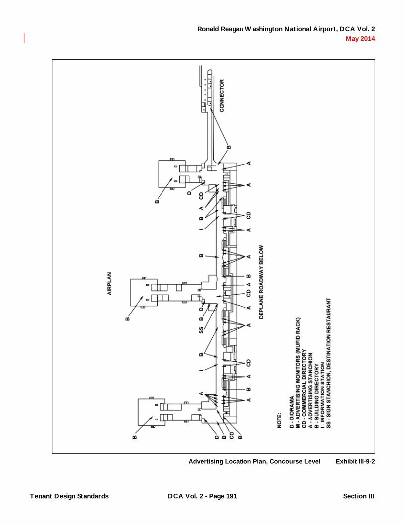
Ronald Reagan Washington National Airport, DCA Vol. 2 May 2014
Advertising Location Plan, Concourse Level Exhibit III-9-2
Tenant Design Standards DCA Vol. 2 - Page 191 Section III

Ronald Reagan Washington National Airport, DCA Vol. 2 May 2014
Advertising Location Plan, Ticketing Level Exhibit III-9-3
Tenant Design Standards DCA Vol. 2 - Page 192 Section III

Ronald Reagan Washington National Airport, DCA Vol. 2 May 2014
Advertising Monitors, Baggage Claim Level Exhibit III-9-4
Tenant Design Standards DCA Vol. 2 - Page 193 Section III

Ronald Reagan Washington National Airport, DCA Vol. 2 May 2014
9.2.4 Sign Stanchions: Illuminated sign stanchions with display cases provided and installed by the Authority for use by the tenants of the ticket level café and destination restaurants.
9.2.5 Poster Racks: Poster racks with brochures holder free standing, non illuminated double-sided poster/sign shall be as follows:
Manufacturer: Lavi Industries Telephone: 800-624-6225 Model: Directrac Sign Frame - SATIN
CHROME Base: Standard Heavy Weighted "H"
Base. Base should be silver color to match SATIN CHROME frame and post
Brochure Holder (Optional)
Brochure Holders should be silver color to match SATIN CHROME frame and post
9.3 Metering
9.3.1 General: Advertising locations are not independently metered.
9.4 General Criteria/Prohibitions
9.4.1 Size/Mounting: The following dimensions are provided for guidance. tenants shall field verify dimensions prior to actual fabrication of inserts.
9.4.1.1 Dioramas: Wall mounted diorama units shall work within the 8' – 0" horizontal and 4' – 0" vertical building modules as shown in Exhibit III-9-5. Tenants shall remove and return to the Authority the high impact wall panels from locations reserved for diorama installations. Dioramas shall be flush mounted with no projections beyond the face of adjacent filler panels. Tenants shall field verify the built condition to determine proper depth of unit. Size of image shall be limited to 83" x 57". A 6 5/16" stainless steel trim
will surround the image surface on the top and two sides as shown on Exhibit III-9-5. A stainless steel filler panel shall be provided below the diorama. The image surface will be flush with the adjacent stainless trim. Stainless steel shall be provided with a bright No. 4 directional polish finish with the grain in the horizontal direction in all aforementioned applications.
9.4.1.2 Monitors: Tenant shall use a 27" diagonal screen high resolution color monitor. Monitor enclosures will accommodate a monitor of dimensions not-to-exceed the following: 2' – 1/16" x 1" – 7 3/16" x 1' - 7½" DVC boxes, if required, shall be floor mounted beneath the claim device enclosure. Tenants shall verify built dimensions of enclosure prior to procuring monitors.
9.4.1.3 Advertising Stanchions: Advertising stanchion insert size shall be a maximum of 2' - 8¾" x 1' - 6¾". Advertising stanchion image area (insert size - dimension of case frame) is limited to 2' - 8¼" x 1' - 6¼". Advertising materials shall be mounted so that when installed in the Authority provided units they do not bend, wrinkle or warp.
Tenant Design Standards DCA Vol. 2 - Page 194 Section III

Ronald Reagan Washington National Airport, DCA Vol. 2 May 2014
Advertising Dioramas Exhibit III-9-5
Tenant Design Standards DCA Vol. 2 - Page 195 Section III

Ronald Reagan Washington National Airport, DCA Vol. 2 May 2014
9.4.1.4 Sign Stanchions: Sign stanchion insert size shall be a maximum of 2' - ¼" x 2' - 6¼". Sign stanchion image area (insert size - dimension of case frame) is limited to 1' - 11¾" x 2' - 5¾". Sign stanchion display case image area shall be 1' – 0" x 2' - 5¾". Illuminated display cases are suitable for the insertion of print graphics that change periodically, such as menus, reviews, specials or seasonal information.
9.4.2 Media
9.4.2.1 Printed Materials: Printed materials shall have art and typography that are computer or photo process generated and/or printed. Professionally executed calligraphy shall be the only acceptable form of hand prepared graphics.
9.4.2.2 Transparencies: The tenant logo/artwork should be reproduced on transparent film or rigid translucent vinyl by photo process from computer generated originals. Scanned four-color images are encouraged. Hand-cut overlays if executed in a professional manner may be acceptable. Hand-cut overlays shall have straight edges that are square and true. Curves and rounds of letter shall be crisp and smooth.
9.4.2.3 Video: Videos shall be executed in broadcast quality format.
9.4.3 Message Content/Media Quality
9.4.3.1 Printed Materials/Transparencies: The tenant will be required to use a professionally trained graphic designer to develop message and visual materials intended for use at advertising locations. Advertising shall have graphics, wording and/or imagery that are clean, clear and crisp in execution. Typography shall be computer generated or of equal quality. Letters shall have smooth and sharp edges. Cut edges shall be straight and true. Words shall be level and parallel to sign casework if providing informational messages. All proposed art for printed material and transparencies for development of advertising media proposed for display in the Terminal will be subject to
Authority review and approval of message content and visual quality.
9.4.3.2 Videos: The tenant will be required to use a professionally trained multi-media consultant to develop promotional video materials. Such consultants shall have a minimum of five years of producing credits. Videos shall be professionally produced, recorded and edited on broadcast quality tape format. The Authority will review and approve all proposed video materials, including scripts and/or story boards prepared to communicate content, style and pace of the video program prior to execution of custom video materials. Story boards shall include proposed visual concepts and/or key images, animation, special effects, backgrounds and graphic messages.
9.4.4 Prohibitions
9.4.4.1 Printed Materials: Inferior reproduction will be rejected. Low contrast complex images or lettering smaller than ⅝" may be considered inappropriate. Primitive execution of artwork is unacceptable. Handwritten copy is unacceptable.
9.4.4.2 Transparencies: Visible seams and light leaks are unacceptable in transparency installations.
9.4.4.3 Videos: Loop tapes shall be no longer than one hour so as to eliminate long segments of signal noise. Audio programs are not permitted.
Tenant Design Standards DCA Vol. 2 - Page 196 Section III

Ronald Reagan Washington National Airport, DCA Vol. 2 May 2014
CHAPTER 10 Miscellaneous Commercial Standards
10.1 Applicability General: the standards contained in this Chapter apply to a variety of commercial or passenger related services that may be located in the Terminal. Such spaces or elements may be provided or occupied by the Authority, by other tenants, by Vendors or by Authority or tenant-procured service operations. Areas include the following with a brief description and exhibits as appropriate.
10.1.1 Ground Transportation Information Centers: A Ground Transportation Information Center, or GTIC, is provided opposite each baggage claim area as shown on Exhibit III-10-1. The GTIC desk will allow for staffing by 2-3 attendants, sale of tickets for various modes of ground transportation, and has provisions for storage and display of a variety of information of interest to passengers and visitors. Immediately behind the desk in a display case for the display of maps or other GTIC related visual information. Adjacent to the desk are areas with phone provisions for contacting rental car companies that are located outside the Terminal Building, as well as local hotel and motel accommodations. Refer to Exhibit III-10-3 for a typical GTIC layout.
10.1.2 Washington Flyer Podium: Freestanding podiums for the sale of tickets for Washington Flyer and/or door-to-door ground transportation operations will be provided by the Authority at the locations shown on Exhibit III-10-1. Refer to Exhibit III-10-4 for a typical Washington Flyer Podium.
10.1.3 Commercial Directories: Illuminated commercial directories will be provided by the Authority as indicated in Exhibit III-10-2 to assist the traveling public in wayfinding to the many retail and food-and-beverage establishments located in Terminal B/C. Commercial directory inserts shall be provided by the retail and food-and-beverage Developers. Film negatives listing the name of the establishment and room number in project standard format shall be provided. Room numbers shall key to adjacent floor
plan artwork. Additional commercial directories, if desired by the Authority, will be located so as not to disrupt passenger movements. Commercial directory casework shall be procured to match the vocabulary established in the Casework Construction Package. Proposed additional locations will be reviewed and approved by the Authority. Modifications to the casework standard that may be required to allow incorporation into an existing space will also be reviewed and approved by the Authority.
10.1.4 Customer Service Centers: Customer service centers are provided at two locations along the North/South Concourse as described in Exhibits III-10-2, III-10-5 and III-10-6. The Authority will provide the storefront with sliding closure doors. Electrical and telecommunications provisions will be as described in Chapter 1. Tenants shall provide all interior finishes, furnishing, casework, fixtures and equipment. A standard building service blade sign frame and insert identifying the area will be provided by the Authority.
10.1.4.1 The Tenant may operate this area as a staffed or self-service center. Recommended services to be located at these Customer Service Centers include:
A. Coin/credit card operated fax.
B. Coin/credit card operated copier.
C. Change machine.
D. FedEx, UPS collection box.
E. Telephone Services/pp2000.
F. Automated Postal Services.
G. Insurance Vending.
H. Express Mail Drop.
I. PC Battery Charging.
Tenant Design Standards DCA Vol. 2 - Page 197 Section III

Ronald Reagan Washington National Airport, DCA Vol. 2 May 2014
Misc. Commercial Locations, Baggage Level Exhibit III-10-1
Tenant Design Standards DCA Vol. 2 - Page 198 Section III

Ronald Reagan Washington National Airport, DCA Vol. 2 May 2014
Misc. Commercial Locations, Concourse Level Exhibit III-10-2
Tenant Design Standards DCA Vol. 2 - Page 199 Section III

Ronald Reagan Washington National Airport, DCA Vol. 2 May 2014
Washington Flyer Podium Exhibit III-10-3
Tenant Design Standards DCA Vol. 2 - Page 200 Section III

Ronald Reagan Washington National Airport, DCA Vol. 2 May 2014
Washington Flyer Podium, Identity and Text Application Exhibit III-10-4
Tenant Design Standards DCA Vol. 2 - Page 201 Section III

Ronald Reagan Washington National Airport, DCA Vol. 2 May 2014
Customer Service Center, Design Control Zone Exhibit III-10-5
Tenant Design Standards DCA Vol. 2 - Page 202 Section III

Ronald Reagan Washington National Airport, DCA Vol. 2 May 2014
Customer Service Center, Elevation N,S Side Exhibit III-10-6
Tenant Design Standards DCA Vol. 2 - Page 203 Section III

Ronald Reagan Washington National Airport, DCA Vol. 2 May 2014
J. Cellular Phone/Pager Rental.
K. Brokerage/Stock Quote Services.
L. Bank marketing/Banking Services.
M. Automated Teller Machines.
N. Automated Foreign Currency Exchange Machines.
O. Computer Work Stations.
10.1.4.2 Tenants are encouraged to maintain an open appearance to the area and use lighting to enhance visibility and opportunity for public recognition. No permanent casework or millwork shall be affixed to the storefront or in the Design Control Zone.
10.1.5 Cable Television: CATV distribution to tenant areas is under development. The Authority will review and approve all public locations proposed by tenants or vendors for the purposes of providing cable television broadcasts. Cable television will occur in designated terminal areas only. The Authority will provide television monitor enclosure boxes and the associated ceiling mounted rack. The enclosure boxes and racks are as described in Exhibit III-10-7. Tenants shall install television monitor enclosures, associated miscellaneous steel supports above the ceiling, and television monitors. Power and signal to each enclosure box shall be provided by the tenant. Duplex receptacles shall be mounted above the finished ceiling. Power and signal shall be fed into the box for connection to the monitor. Tenants shall provide a 27" diagonal screen high resolution color monitor. Monitor enclosures will accommodate a monitor of dimensions not-to-exceed the following: 2' – 1/6" x 1' – 73/16" x 1' - 7½". Tenants shall verify built dimensions of enclosure prior to procuring monitors. Television monitors in freestanding casework are prohibited.
10.1.6 Shoeshine Stands: Shoeshine stand locations have been established at the North, Center and South Piers
as shown in Exhibit III-10-2. Shoeshine stands, storage closets and associated display cases will be provided and installed by the Authority for use by approved Tenants as shown in Exhibit III-10-8. If additional shoeshine stands are desired by the Authority, their preferred location shall be in an alcove similar to the arrangement shown in Exhibit III-10-9. One empty closet per shoeshine stand is recommended. Casework, chairs and anti-fatigue mats shall be procured to match the vocabulary established in the Casework and Terminal Construction Packages. Proposed additional locations will be reviewed and approved by the Authority. Modifications to the casework standards that may be required to allow incorporation into an existing space will also be reviewed and approved by the Authority. A standard building service blade sign frame and insert identifying the area will be provided by the Authority. Tenants shall maintain the area as described in Exhibit III-10-9. All advertising, signage and displays associated with the shoeshine stand shall be located in the cabinet provided and shall meet the criteria indicated in Exhibits III-10-10 and III-10-11.
10.1.7 Newspaper Dispenser Racks: Newspaper vending areas will be established and dispenser racks procured and installed by the Authority. Additional vending locations will be reviewed and approved by the Authority prior to procurement and installation of additional racks. Preferred locations include in an alcove similar to the arrangement shown in Exhibit III-10-9. If practical, a stainless steel cap shall be provided in the vocabulary established in the Casework Construction Package. Approved dispenser racks are as manufactured by GeoRack, Inc. Advertising/Additional Signs: Sign placards on, over or above boxes on a temporary or permanent basis are prohibited.
10.1.8 Lockers: Locker locations are established at the North, Center, and South Piers and at the Connector. Lockers will be procured by the Authority.
Tenant Design Standards DCA Vol. 2 - Page 204 Section III

Ronald Reagan Washington National Airport, DCA Vol. 2 May 2014
Ceiling Hung Monitors, Pier Gates, CNN Monitors Exhibit III-10-7
Tenant Design Standards DCA Vol. 2 - Page 205 Section III

Ronald Reagan Washington National Airport, DCA Vol. 2 May 2014
Shoeshine Stand Exhibit III-10-8
Tenant Design Standards DCA Vol. 2 - Page 206 Section III

Ronald Reagan Washington National Airport, DCA Vol. 2 May 2014
Shoeshine Stand Locker and Newspaper Alcove Exhibit III-10-9
Tenant Design Standards DCA Vol. 2 - Page 207 Section III

Ronald Reagan Washington National Airport, DCA Vol. 2 May 2014
Shoeshine Stand Storage and Display Criteria Exhibit III-10-10
Tenant Design Standards DCA Vol. 2 - Page 208 Section III

Ronald Reagan Washington National Airport, DCA Vol. 2 May 2014
Shoeshine Stand Graphics and Signage Criteria Exhibit III-10-11
Tenant Design Standards DCA Vol. 2 - Page 209 Section III

Ronald Reagan Washington National Airport, DCA Vol. 2 May 2014
Additional locker locations, if required, will be reviewed and approved by the Authority prior to procurement and installation of additional lockers. Preferred locations include in an alcove similar to the arrangement shown in Exhibit III-10-9. Lockers used throughout the Terminal shall be of a single variety.
10.1.9 Baggage Carts/Dispensers
10.1.9.1 Baggage Carts/Dispenser Locations: Baggage carts/dispenser locations have been established by the Authority. Additional locations, if required, will be reviewed and approved by the Authority prior to procurement and installation of additional units. Layout shall ensure that there is adequate space at either end of the dispenser for removal and insertion of the carts themselves without damage to adjacent surfaces or other freestanding elements.
A. Instructional Signage/Supplemental Advertising: Instructional signage shall be integral to the cart system and shall be permanently affixed. Instructional signage and graphics shall comply with the criteria set forth in Chapter 5. Supplemental advertising, if desired by the vendor, shall be reviewed and approved by the Authority prior to display or installation.
B. Installation: All wiring shall be concealed. Any floor plates shall be set flush with adjacent floor surfaces. Floor plate edges shall be ground smooth with no protruding fasteners.
10.1.9.2 Personal luggage carts/dispenser shall be of a single variety.
10.1.10 Luggage Storage and Sales: A luggage storage and sales area is centrally located on the Baggage Claim Level. This area provides alternative provisions for short and long term luggage storage and luggage/luggage accessory sales. The Authority will procure and install the closure grille, storage room, associated shelving inside the storage room, and baggage conveyor and x-ray equipment
for use by an approved tenant. A standard building service blade sign identifying the area will be provided by the Authority. Prohibitions: No signing, displays or merchandise may be mounted to or hung from base building walls, rolling grille surfaces, or casework within the Design Control Zone.
10.1.11 United Stated Postal Services: Post office vending machines shall occur in Customer Services Centers only. The Authority will review and approve the location and design of the development of any independent postal operation or mailboxes that may front on public space within the Terminal. No free-standing mail box units in public circulation spaces of the Terminal will be permitted.
10.2 General Criteria/Prohibitions
10.2.1 General Criteria: The Authority, other tenants, Vendors or other Authority or tenant procured service operations or providers of miscellaneous commercials areas or elements shall comply with the general design standards contained in Chapter 5 of this document. In addition, the following specific criteria shall apply.
10.2.2 Modifications/Alterations: Tenants, including the Authority as tenant, may not alter controlled materials or base building elements without prior approval of the Authority. This includes columns within any area, structural elements above storefronts, floors, walls or ceiling surfaces. All proposed modifications to existing areas regardless of the tenant or occupant will be reviewed by the Authority. Such modifications include changes to finish materials or color, modifications to casework or millwork, the addition or removal of signage, the addition of free standing casework, including, but not limited to, interactive video units, insurance vending, automatic teller or ticket machines, facsimile or copy machines or postal vending units, replacement of or changes to lighting, furnishings or fixtures. Approved new construction or installations of new or additional elements shall return existing floor, walls and ceiling surfaces to their original condition.
Tenant Design Standards DCA Vol. 2 - Page 210 Section III

Ronald Reagan Washington National Airport, DCA Vol. 2 May 2014
10.2.3 Storage: Storage of supplies, merchandise, equipment or furnishings associated with administrative or business functions shall occur in areas provided: either in store rooms or casework. Tenants and other occupants shall maintain an uncluttered appearance in areas visible from public circulation areas of the Terminal. Display of personal mementos in areas visible to the public is prohibited.
10.2.4 Signing/Graphics Inside Designated Areas: Standard vendor signing may be acceptable if reviewed and approved by the Authority. Sign application and method of attachment shall be permanent and vandal proof. Freestanding or attached advertising units that are part of the manufacturer’s standard system may be acceptable if reviewed and approved by the Authority. Such systems shall not intrude into the public way beyond designated locations or interfere with wayfinding by being visually intrusive into the environs. Such criteria shall be applicable to standard commercial elements, including but not limited to personal luggage carts/dispensers, lockers and newspaper dispensers. Desk bar signing used to identify attendants or to present hours of operation shall comply with the criteria provided in Exhibit III-10-12.
10.2.5 Music/Television: In keeping with a professional and service oriented Terminal environment, personal portable televisions, radios, tape or compact disk players are discouraged at miscellaneous commercial locations, including but not limited to the Ground Transportation Information Center, the Washington Flyer Podiums, the shoeshine stands, or other sales or service counters.
10.2.6 Furnishings/Fixtures/Equipment: The Authority will review and approve tenant provided furnishings/fixtures/equipment on a periodic basis. Tenants may be required to replace or repair worn, damaged, frayed, shabby or broken items.
10.2.7 Brochure Displays: Tenants or occupants who wish to offer or display brochures or other literature/materials at any location, for which provisions have not otherwise been included in the design of Authority provided casework, shall procure clear acrylic easels or holders. Maximum overall dimension shall be 8½" x 11". Such fixtures may not be affixed to any casework or building surface either on a permanent or semi-permanent basis. Tenants and occupants shall review catalog cuts or sample displays with the Authority prior to procurement for use in their areas.
Tenant Design Standards DCA Vol. 2 - Page 211 Section III

Ronald Reagan Washington National Airport, DCA Vol. 2 May 2014
Tenant Desk Bar Signs Exhibit III-10-12
Tenant Design Standards DCA Vol. 2 - Page 212 Section III

Ronald Reagan Washington National Airport, DCA Vol. 2 May 2014
LIST OF EXHIBITS
LIST OF EXHIBITS
SECTION III: Tenant Design Standards .............................................................................................................................. 13
CHAPTER 1 General .............................................................................................................................................................. 13
Exhibit III-1-1 Terminal Designations .................................................................................................................... 14 Exhibit III-1-2 AEP Location Plan, Concourse Level ............................................................................................ 20 Exhibit III-1-3 AEP Location Plan, Ticket Level .................................................................................................... 21
CHAPTER 2 AIRLINE SHELL SPACES ................................................................................................................................ 31
CHAPTER 3 Retail Shell Spaces .......................................................................................................................................... 39
Exhibit III-3-1 Retail Locations, Baggage Level .................................................................................................... 40 Exhibit III-3-2 Retail Locations, Concourse Level ................................................................................................. 41 Exhibit III-3-3 Retail Locations, Ticketing level ..................................................................................................... 42 Exhibit III-3-4 Retail Kiosk Wall Unit Component ................................................................................................. 44 Exhibit III-3-5 Food and Beverage and Retail Merchandising Unit, Peir Locations .............................................. 47
CHAPTER 4 Food-and-Beverage Shell Spaces .................................................................................................................. 49
Exhibit III-4-1 Food and Beverage Locations, Concourse Level .......................................................................... 50 Exhibit III-4-2 Food and Beverage Locations, Ticketing Level ............................................................................. 51 Exhibit III-4-3 Public Square Kiosk ....................................................................................................................... 54 Exhibit III-4-4 Public Square Kiosks Casework (A) ............................................................................................... 55 Exhibit III-4-5 Public Square Kiosks Casework (B) ............................................................................................... 56 Exhibit III-4-6 Public Square Kiosks Signage ....................................................................................................... 57 Exhibit III-4-7 Ticketing Level Café, Overall Plan ................................................................................................. 59 Exhibit III-4-8 Ticketing Level Café, Details .......................................................................................................... 60 Exhibit III-4-9 Ticketing Level Café, Closure System ........................................................................................... 61 Exhibit III-4-10 Destination Restaurant, Concourse Level ...................................................................................... 64 Exhibit III-4-11 Destination Restaurant, Club Level ................................................................................................ 65 Exhibit III-4-12 Vacated F and B Storefront ............................................................................................................ 69
CHAPTER 5 General Design Standards .............................................................................................................................. 71
Exhibit III-5-1 Demising Wall Location Criteria ..................................................................................................... 72 Exhibit III-5-2 NS Concourse Storefronts W Col Line C ....................................................................................... 73 Exhibit III-5-3 Storefront NS Concourse Vertical Support Typical Details ............................................................ 76 Exhibit III-5-4 Storefront NS Concourse Typical Overhead Grille Details ............................................................. 77
DCA Vol. 2 - Page 213 List of Exhibits

Ronald Reagan Washington National Airport, DCA Vol. 2 May 2014
Exhibit III-5-5 Storefront Piers Typical Overhead Grille Details ............................................................................ 78 Exhibit III-5-6 Axonometric at DCZ Concourse Side Coiling Grille ....................................................................... 79 Exhibit III-5-7 Storefront NS Concourse Typical Details ....................................................................................... 81 Exhibit III-5-8 Storefront NS Concourse Col Connection ...................................................................................... 82 Exhibit III-5-9 Entry Doors NS Concourse Typical Details .................................................................................... 83 Exhibit III-5-10 Storefront NS Concourse Butt Glazing Details ............................................................................... 85 Exhibit III-5-11 Storefront Pier Butt Glazing Details ................................................................................................ 86 Exhibit III-5-12 Butt Glazed Sotefronts Pier Food Court Areas .............................................................................. 87 Exhibit III-5-13 Hour of Operation, Signing and Graphics Criteria .......................................................................... 90 Exhibit III-5-14 Exposed Pipe, Aesthetic Treatment ............................................................................................... 94 Exhibit III-5-15 Pipe Shroud .................................................................................................................................... 95
CHAPTER 6 Airline Tenant Design Standards ................................................................................................................... 97
Exhibit III-6-1 Curbside Check-In Options ............................................................................................................ 99 Exhibit III-6-2 Curbside Check-In, Typical Plan .................................................................................................. 100 Exhibit III-6-3 Curbside Check-In, Typical Elevation .......................................................................................... 101 Exhibit III-6-4 Curbside Check-In, Typical Section ............................................................................................. 102 Exhibit III-6-5 Curbside Check-In, Overhead Door ............................................................................................ 103 Exhibit III-6-6 Curbside Check-In, Podium Elevation ......................................................................................... 104 Exhibit III-6-7 Curbside Check-In, ....................................................................................................................... 106 Exhibit III-6-8 Curbside Check-In, Podium Details ............................................................................................ 107 Exhibit III-6-9 Ticket Counters, Typical Elevation ............................................................................................... 108 Exhibit III-6-10 Ticket Counters, Doghouse Elevation .......................................................................................... 109 Exhibit III-6-11 Ticket Counter Elevation, 2-Position Elevation ............................................................................ 110 Exhibit III-6-12 Ticket Counter Elevation, 2-Position Plan .................................................................................... 111 Exhibit III-6-13 Ticket Counter Elevation at Bagwell ............................................................................................. 112 Exhibit III-6-14 Ticket Counter at Backwall ........................................................................................................... 113 Exhibit III-6-15 Shuttle Counters Section, Detail at Backwall ............................................................................... 115 Exhibit III-6-16 Shuttle Ticket Counters, South Pier ............................................................................................. 116 Exhibit III-6-17 Shuttle Ticket Counter .................................................................................................................. 117 Exhibit III-6-18 Bridge Check-In Plan at North Bridge .......................................................................................... 119 Exhibit III-6-19 Bridge Check-In Section ............................................................................................................... 120 Exhibit III-6-20 Airline Clubs Design Control Zones ............................................................................................. 122 Exhibit III-6-21 Airline Clubs Elevation at Interior Facade .................................................................................... 123 Exhibit III-6-22 Airline Clubs Elevation at Interior Facade .................................................................................... 125 Exhibit III-6-23 Airline Clubs Section through Curtainwall .................................................................................... 126 Exhibit III-6-24 Airline Clubs, Wayfinding at Concourse ....................................................................................... 128 Exhibit III-6-25 Airline Clubs, Signing at Stairs ..................................................................................................... 129 Exhibit III-6-26 Airline Clubs, Signing at Elevator ................................................................................................. 130 Exhibit III-6-27 Airline Clubs, Lobby Plan ............................................................................................................. 131 Exhibit III-6-28 Airline Clubs, Typical Entrance .................................................................................................... 132 Exhibit III-6-29 Airline Clubs, Typical Entrance .................................................................................................... 133
DCA Vol. 2 - Page 214 List of Exhibits

Ronald Reagan Washington National Airport, DCA Vol. 2 May 2014
Exhibit III-6-30 Baggage Service Office, Typical Plan .......................................................................................... 134 Exhibit III-6-31 Baggage Service Office, Storefront Options ................................................................................ 136 Exhibit III-6-32 Baggage Service Office, Panel Option A ..................................................................................... 137 Exhibit III-6-33 Baggage Service Office, Panel Option B ..................................................................................... 138 Exhibit III-6-34 Baggage Service Office, Panel Option C ..................................................................................... 139 Exhibit III-6-35 Baggage Service Office, Panel Option D ..................................................................................... 140 Exhibit III-6-36 Apron Level, Typical Elevation at Gate Bridge ............................................................................. 142 Exhibit III-6-37 Apron Operations, Elevation Options ........................................................................................... 143 Exhibit III-6-38 Apron Operations, Elevation Options ........................................................................................... 144 Exhibit III-6-39 Hold Room Plan Seating Guidelines ............................................................................................ 146 Exhibit III-6-40 Gate Counter ................................................................................................................................ 149 Exhibit III-6-41 Gate Counter ................................................................................................................................ 150 Exhibit III-6-42 Gate Counter, Plans ..................................................................................................................... 151 Exhibit III-6-43 2-Position Backscreen Graphics .................................................................................................. 152 Exhibit III-6-44 3-Position Backscreen Graphics .................................................................................................. 153 Exhibit III-6-45 Backscreen Elevations ................................................................................................................. 154 Exhibit III-6-46 Ticket Lift, Ticket Service Podium ................................................................................................ 155 Exhibit III-6-47 Poster and Brochure Rack ........................................................................................................... 156 Exhibit III-6-48 Poster and Brochure Rack, Typical Details .................................................................................. 157 Exhibit III-6-49 Loading Bridge ............................................................................................................................. 159
CHAPTER 7 Retail Tenant Design Standards ................................................................................................................... 161
Exhibit III-7-1 Signboard Location Criteria Retail Kiosks (A) .............................................................................. 164 Exhibit III-7-2 Signboard Location Criteria Retail Kiosks (B) .............................................................................. 165
CHAPTER 8 Food-and-Beverage Tenant Design Standards ........................................................................................... 169
Exhibit III-8-1 Design Control Zone Public Square Kiosks ................................................................................. 174 Exhibit III-8-2 Backwall and Alcove Public Square Kiosks ................................................................................. 175 Exhibit III-8-3 Design Control Zone Public Square Kiosks ................................................................................. 176 Exhibit III-8-4 Backwall and Alcove Options, Public Square Kiosks ................................................................... 177 Exhibit III-8-5 Public Square Kiosks Signband Detail ......................................................................................... 178 Exhibit III-8-6 FF and E Arrangement Public Square Kiosks .............................................................................. 180 Exhibit III-8-7 Design Control Zone, Ticket Level Cafe ....................................................................................... 181 Exhibit III-8-8 Design Control Zone, Back Bar Aea ............................................................................................ 182 Exhibit III-8-9 Concourse RestaurantHandrail .................................................................................................... 187
CHAPTER 9 Advertising Tenant Design Standards ......................................................................................................... 189
Exhibit III-9-1 Advertising Location Plan, Baggage Claim Level ......................................................................... 190 Exhibit III-9-2 Advertising Location Plan, Concourse Level ................................................................................ 191 Exhibit III-9-3 Advertising Location Plan, Ticketing Level ................................................................................... 192 Exhibit III-9-4 Advertising Monitors, Baggage Claim Level ................................................................................. 193
DCA Vol. 2 - Page 215 List of Exhibits

Ronald Reagan Washington National Airport, DCA Vol. 2 May 2014
Exhibit III-9-5 Advertising Dioramas ................................................................................................................... 195
CHAPTER 10 Miscellaneous Commercial Standards ...................................................................................................... 197
Exhibit III-10-1 Misc Commercial Locations, Baggage Level ............................................................................... 198 Exhibit III-10-2 Misc Commercial Locations, Concourse Level ............................................................................ 199 Exhibit III-10-3 Washington Flyer Podium ............................................................................................................ 200 Exhibit III-10-4 Washington Flyer Podium, Identity and Text Application ............................................................. 201 Exhibit III-10-5 Customer Service Center, Design Control Zone .......................................................................... 202 Exhibit III-10-6 Customer Service Center, Elevation N,S Side ............................................................................. 203 Exhibit III-10-7 Ceiling Hung Monitors, Pier Gates, CNN Monitors ...................................................................... 205 Exhibit III-10-8 Shoeshine Stand .......................................................................................................................... 206 Exhibit III-10-9 Shoeshine Stand Locker and Newspaper Alcove ........................................................................ 207 Exhibit III-10-10 Shoeshine Stand Storage and Display Criteria ............................................................................ 208 Exhibit III-10-11 Shoeshine Stand Graphics and Signage Criteria ......................................................................... 209 Exhibit III-10-12 Tenant Desk Bar Signs ................................................................................................................ 212
DCA Vol. 2 - Page 216 List of Exhibits

Ronald Reagan Washington National Airport, DCA Vol. 2 May 2014
INDEX
Note: Page numbers followed by e and t indicate Exhibits and Tables, respectively.
A accessibility, Airline Self Service Kiosks, 37 ADA. See Americans with Disabilities Act (ADA) advertising
airline tenants, 148 stanchions for, 189, 194, 196 on temporary partitions, 45
advertising tenants baggage claim level, 190e Concourse level, 191e dioramas, 189, 194, 195e general criteria, 194, 196 locations governed by standards, 189 monitors, 189, 193e, 194 shell spaces, 189, 194 Ticketing level, 192e
AEP (Architectural Enhancement Program) Concourse level, 20e description of, 19 Ticketing level, 21e
Airline Self Service Kiosks, 36–37 airline shell spaces
casework, 35–37 communication systems, 32–33 electrical/lighting, 31–32 equipment, 32 metering, 31 offices, ATOs, and clubs, 33–34 operations, 34–35 signing, 32 storefronts, Terminal B/C, 31 telecommunications and special systems, 31 walls, 31
airline tenants. See also clubs, airline advertising, 148 apron operations areas, 141, 142–144e, 145 backscreen elevations, 154e backscreen graphics, 152–153e baggage claim lobby, 148 baggage service offices, 127, 134e, 135, 136–140e, 141 bridge check-in, 118, 119–120e curbside check-in, 98, 99–104e, 105, 106–107e equipment/fixtures, 148, 158 fire suppression system, 24 gate counters, 149–151e general criteria/prohibitions, 97–98 hold rooms, 145, 146e, 147–148 loading bridges, 159e locations governed by design standards, 97 music, background, 97 poster and brochure racks, 148, 156–157e
shuttle ticket counters and backwalls, 114, 115–117e, 118
signage, 97–98, 105, 148, 152-153e telecommunications, 97 ticket counters and backwalls, 105, 108–113e, 114 ticket lift, ticket service podium, 155e
airline ticket counters, 35 airline ticket offices (ATOs), 33 airside dumpsters, 158 aisles, clear, in airline hold rooms, 147 alcoves
newspaper, 207e Public Square Kiosks, 175e, 177e
alterations to buildings, 210 aluminum, as material or finish, 74 Americans with Disabilities Act (ADA), compliance with, 27–
28 antennas, 91 anti-fatigue mats, 33, 91, 105 applicability
of commercial standards, 197 of design standards, 17, 71
apron operations areas elevation at gate bridge, 142e elevation options, 141, 143–144e, 145 general criteria, 141
Architectural Enhancement Program (AEP) Concourse level, 20e description of, 19 Ticketing level, 21e
AR INC., 32 Automatic Ticket Sales Machines, 114, 118
B backscreens
airline shell spaces, 35 elevations, 154e gate counters, 148 graphics
2-position, 152e 3-position, 153e
backwalls. See also ticket counters and backwalls kiosks, 163 North/South Concourse storefronts, 162, 171 Public Square Kiosks, 173, 175e, 177e shuttle counters section, detail at, 115e signage, 105, 114
bacteriological issues, 28 baggage carts/dispensers, 210 baggage claim
lobby, 148 retail shell spaces, 39–43 signage, 43
DCA Vol. 2 - Page 217 Index

Ronald Reagan Washington National Airport, DCA Vol. 2 May 2014
baggage claim level advertising location plan, 190e advertising monitors, 193e commercial locations, 198e luggage storage and sales area, 210 retail locations, 40e
Baggage Information Displays (BIDS), airline shell spaces, 31
baggage service offices Design Control Zone, 135 general criteria, 127 panel options
A, 137e B, 138e C, 139e D, 140e
signage, 141 storefront options, 135, 136e, 141 typical plan, 134e walls, 33
banners, 114 bar signs, tenant desks, 212e BIDS (Baggage Information Displays), airline shell spaces,
31 blade signs, North/South Concourse storefronts, 172 boarding bridges, 32 bottom bars for storefronts, 80 boxes
luggage sizing, 148 monitor enclosure, advertising, 189
bridge check-in, 118, 119–120e bridges
boarding, 32 gate, typical elevation at, 142e loading, 158, 159e
Bridgewell Café, 185–186 brochure displays
holders for, 89, 211 racks
advertising, 194 airline, 35–36, 148, 156–157e
building directories, 27 building envelope design criteria, 26 buildings. See also terminals (buildings)
modifications or additions to, 210 Terminal B/C description, 13, 15
butt joint glazed storefronts, 84, 85–87e
C cable television (CATV) systems
Authority provided, 23 in tenant areas, 204
cabling tenant lease areas, 22–23 tenant spaces, 97
cafés. See also Ticket Level Café
Bridgewell, 185–186 seating and tables, 179
carts, tray return, 67 cases, food display, 170 casework
airline shell spaces, 35–37 airline tenants, 148 bridge check-in, 118 curbside check-in, 105 Public Square Kiosks, 53, 55–56e retail kiosks, 43 Ticket Level Café, 62
CATV (cable television) system Authority provided, 23 in tenant areas, 204
ceilings airline shell spaces, 34 airline tenants, 124 Bridgewell Café, 185 Concourse restaurant seating areas, 186 Destination Restaurant, 63, 184 food-and-beverage shell spaces, 49 general building shell spaces, 22 kiosks, 53 North/South Concourse storefronts, 162, 171–172 Public Square Kiosks, 58 retail shell spaces, 39
chemical toxicity issues, 28 chilled water system, temperatures, 25 cladding, exterior, 15 clear aisles in airline hold rooms, 147 closure systems
Public Square Kiosks, 58 retail merchandising units, 167 Ticket Level Café, 61e, 62
Club level, Destination Restaurant, 65e clubs, airline
ceilings, 124 Design Control Zone, 118, 121, 122e elevation at interior facade, 123e, 125e lighting, 124 lobbies/entries, 127, 131–133e section through curtainwall, 126e signage, 129–130e walls, 33 wayfinding, 127, 128e window treatments, 124
colors Airline Self Service Kiosks, 36 tenant areas, 74 Terminal B/C, 15, 16–17t
commercial directories, 197 commercial programs. See also food-and-beverage
tenants; retail tenants design standards, 18–19 signing guidelines inside designated areas, 211
commercial standards
DCA Vol. 2 - Page 218 Index

Ronald Reagan Washington National Airport, DCA Vol. 2 May 2014
applicability of, 197 baggage carts/dispensers, 210 baggage claim level, 198e cable television distribution, 204 Concourse level, 199e customer service centers, 197, 202–203e, 204 general criteria, 210–211 Ground Transportation Information Center, 197 lockers, 204, 210 luggage storage and sales, 210 monitors, ceiling hung, 205e newspaper dispenser racks, 204 shoeshine stands, 204, 206–209e United States Postal Services, 210 Washington Flyer podiums, 197, 200–201e
communication systems, airline shell spaces, 32–33, 36 Concourse Level
advertising location plan, 191e Architectural Enhancement Program, 20e commercial locations, 199e Destination Restaurant, 63–66, 64e food-and-beverage locations, 50e restaurant handrail, 187e restaurant seating, 186 retail locations, 41e retail shell spaces, 39–43
concourses. See North/South Concourse Connector to Terminal A
exterior walls, 34 food-and-beverage tenants, 172–173 interior materials, 15 storefronts, 43, 162–163
construction at demising walls, 71 control modules, HVAC, 27 counters
airline gate, 148, 149–151e food-and-beverage tenants, 170, 183
credit card acceptance signs, 89 curbside check-in
general criteria, 98, 105 heating units, 33 options, 99e overhead door, 103e podiums, 98, 104e, 106–107e typical elevation, 101e typical plan, 100e typical section, 102e
curtainwalls airline clubs section through, 126e Destination Restaurant, 184 exterior, window treatments, 91 North/South Concourse storefronts, 162, 171
customer service centers, 197, 202–203e, 204
D decorations, seasonal and holiday, 93
demising walls construction by tenants at, 71 food-and-beverage tenants, 170 location criteria, 71, 72e
Design Control Zones airline clubs, 118, 121, 122e back bar area, 182e baggage service offices, 135 Concourse Restaurants, 186 customer service center, 202e definition of, 71 Destination Restaurant, 183 merchandising displays, 89, 91 Public Square Kiosks, 174e, 176e retail kiosks, 163 Ticket Level Café, 179, 181e
designers, graphic, 196 Design Manual
applicability of, 3 organization of, 3–4 overview of, 18 revisions to, 5–6
design standards applicability of, 17, 71 enforcement of, 93 general criteria/prohibitions, 71–93 tenant, 13–15, 17–19
desk bar signs, 212e Destination Restaurant
Club level, 65e Concourse level, 64e design standards, 183–185 general criteria, 63
dining room, Historic Preservation Design Guidance for, 18 dioramas, 189, 194, 195e directories
building, 27 commercial, 197
display cases for food, 170 display lighting
acceptable, 89 food-and-beverage tenants, 169 retail tenants, 161
docks, loading food and beverage support spaces, 66 retail support spaces, 45
documents Authority design-related, 17–18 compliance with, 4
doors apron operations areas, 145 entry, North/South Concourse storefronts, 83e general building shell spaces, 22 overhead, curbside check-in, 103e
dumpsters, airside, 158
DCA Vol. 2 - Page 219 Index

Ronald Reagan Washington National Airport, DCA Vol. 2 May 2014
E Eames Tandem Sling seating, 147 electrical closets, 24 electrical loads, 26t electrical metering, 24 electrical systems
airline shell spaces, 31–32, 34 Destination Restaurant, 63 Public Square Kiosks, 58 Ticket Level Café, 62
electric unit heaters, temporary, 25 elevators
airline clubs, signing at, 130e Destination Restaurant, 66
enclosed storefronts, 80 enforcement of design standards, 93 entries
airline clubs, 127, 132–133e North/South Concourse, 83e
environmental quality, indoor, 28 equipment
airline, 148–158 airline shell spaces, 32 commercial tenants, 211 food-and-beverage tenants, 170 lighting, 161 mobile, 91 tenant spaces, 91
equipment rooms, radio communications, 32–33 exhaust systems
food-and-beverage shell spaces, 52 general building shell spaces, 26 hoods, 92–93 tenant areas, 92–93
exposed pipe, aesthetic treatment of, 93, 94e exterior cladding, 15
F fan coil units, 92 FF and E arrangement, Public Square Kiosks, 180e FIDS (Flight Information Displays), airline shell spaces, 31 fire alarm systems, general building shell spaces, 25 fire extinguishers, 92 fire suppression systems
general building shell spaces, 24–25 tenant areas, 92
fixtures airline tenants, 148–158 commercial tenants, 211 food-and-beverage tenants, 170 Public Square Kiosks, 58 tenant areas, 91
flexibility of commercial mix, 19 Flight Information Displays (FIDS), airline shell spaces, 31 flooring/floors
airline ticket counters, 33 Bridgewell Café, 185 Concourse restaurant seating, 186 Destination Restaurant, 63, 184 food-and-beverage shell spaces, 49 kiosks, 43, 45, 53, 163 North/South Concourse storefronts, 171 Public Square Kiosks, 173 retail merchandising units, 166 retail shell spaces, 39 Ticket Level Café, 58
floor slabs, 22 floor structure, tenant areas, 91 food-and-beverage shell spaces
categories of, 49 ceilings, 49 Concourse level, 50e Destination Restaurant, 63–66, 64–65e electrical/lighting, 49, 52 flooring, 49 mechanical systems, 52 North/South Concourse and Piers, 49, 52 plumbing, 52 Public Square Kiosks, 53, 54–57e, 58 signage, 52, 169–170 storefronts, 49 support spaces, 66 telecommunications, 49 Ticketing level, 51e Ticket Level Café, 58, 59–61e, 62–63 vacated, 67–68, 69e walls, 49
food-and-beverage tenants Bridgewell Café, 185–186 Concourse restaurant seating, 186 Destination Restaurant, 183–185 fire suppression system, 25 fixtures, millwork, furniture, and equipment, 170 general criteria, 169–171 locations governed by standards, 169 music, 170 prohibitions, 186 Public Square Kiosks
backwall and alcove, 175e, 177e Design Control Zone, 174e, 176e FF and E arrangement, 180e general criteria, 173, 179 sign band detail, 178e
queue control, 170–171 signage, 52, 169–170, 171 storefronts, 171–173 Ticket Level Café, 179, 183
food court, Pier location, 47e, 87e food display cases, 170 fume exhaust hoods, 92–93 furnishings
commercial tenants, 211
DCA Vol. 2 - Page 220 Index

Ronald Reagan Washington National Airport, DCA Vol. 2 May 2014
tenant areas, 91 furniture
Bridgewell Café, 185–186 Concourse restaurant seating areas, 186 Destination Restaurant, 185 food-and-beverage tenants, 170 kiosks, 166 Public Square Kiosks, 58, 179 retail merchandising units, 167 Ticket Level Café, 62
Futura typeface, 27
G gate bridge, typical elevation at, 142e gate counters
airline, 148, 149–151e airline shell spaces, 35
gate designations, 147 glare, elimination of, 89 glass, spandrel, 74 graphic designers, 196 graphic symbols on signs, 27 grilles
axonometric at DCZ Concourse side coiling, 79e overhead
North/South Concourse, 77e open storefronts, 75, 80 Piers, 78e
security, 58, 61e, 62 side coiling, 79e
Ground Transportation Center, commercial standards, 197
H handrails, 186, 187e heaters, electric unit, temporary, 25 Herman Miller seating, 166, 179 historic preservation of Dining Room, 18 hold rooms, airline
casework, 148 general criteria, 145, 147 seating guidelines, 146e signage, 148
hoods, fume exhaust, 92–93 hot water systems, temperatures, 25 hours of operation signs, 89, 90e HVAC (heating, ventilating, and air conditioning) systems
airline shell spaces, 33, 34–35 Concourse/Piers/Baggage Claim, 43 Destination Restaurant, 63 food-and-beverage shell spaces, 52, 58 general building shell spaces, 25–27 indoor environmental quality and, 28 tenant areas, 92 Ticket Level Café, 62
water metering, 23
I illumination levels
food-and-beverage tenants, 169 general criteria, 84, 88
indoor conditions, temperatures, 25, 26t indoor environmental quality, 28–29 installation
of Airline Self Service Kiosks, 37 of baggage carts/dispensers, 210
K kiosks
Airline Self Service, 36–37 casework, 53 ceilings, 53 electrical, 58 flooring, 43, 53, 163 furniture, 58, 166 lighting, 45, 58, 163 mechanical systems, 58 panels, 43, 45 plumbing, 58 Public Square
backwall and alcove, 175e, 177e casework, 55–56e Design Control Zone, 174e, 176e FF and E arrangement, 180e food-and-beverage tenant spaces, 173, 179 general criteria, 53, 54e, 58 signage, 57e, 173, 179 sign band detail, 178e vacated, 68
queue control, 166 retail, 43, 44e, 45 security grilles/closure system, 58 sidewalls, 163 signage, 53, 164–165e vacated, 45, 46, 68 wall display/storage units, 44e walls, 53
kitchens, Destination Restaurant, 66
L labels, manufacturer, 88 landscaping, interior, 93 lease lines
criteria for, 71 signage inside
commercial, 211 menu boards, 169–170
signage outside
DCA Vol. 2 - Page 221 Index
Ronald Reagan Washington National Airport, DCA Vol. 2 May 2014
food-and-beverage tenants, 171 general, 93
lettering on signs, size of, 89 life safety systems, 25, 92 lift podiums
airline, 148, 155e airline shell spaces, 35
lighting airline shell spaces, 31–32 airline tenants, 124 artificial, 29 Bridgewell Café, 185 Concourse restaurant seating areas, 186 Destination Restaurant, 63, 184–185 display, 89, 161, 169 electrical meters and, 24 food-and-beverage shell spaces, 49 food-and-beverage tenants, 52, 169 glare and, 89 kiosks, 45, 58, 163 neon, 91 Public Square Kiosks, 173 retail merchandising units, 166 retail tenants, 161 temporary, 24 tenant areas, 84, 88 Ticket Level Café, 62
loading bridges, 158, 159e loading docks
food and beverage support spaces, 66 retail support spaces, 45
loads, electrical, 26t lobbies
airline clubs, 127, 131e baggage claim, 148
lockers, 204, 207e, 210 luggage. See also baggage claim; baggage claim level;
baggage service offices sizing boxes, 148 storage and sales area, 210
M Main Telecommunications Facility (MTF), 22 Main Terminal. See Terminal A manholes, Main Telecommunications Facility, 22 manufacturer labels, 88 manufacturers of storefronts, 84 Master Clock system, 23 materials
Airline Self Service Kiosks, 36 printed, 196 tenant areas, 74 Terminal B/C, 15
mats, anti-fatigue, 33, 91, 105 mechanical systems. See also HVAC (heating, ventilating,
and air conditioning) systems
Concourse/Piers/Baggage Claim, 43 Destination Restaurant, 63 food-and-beverage tenants, 52 kiosks, 58 tenant areas, 92 Ticket Level Café, 62
media, advertising, 196 menu boards, 169–170, 179 merchandising displays
Design Control Zone, 89, 91 lighting, 169 Public Square Kiosks, 179 retail merchandising units, 166–167 retail tenants, 161 Ticket Level Café, 183
messages on advertising media, 196 on signs, typeface for, 27
metering airline shell spaces, 31 electrical and lighting, 24 general shell spaces, 23–24 natural gas, 24
Metro bridge, 15 mobile equipment, 91 modifications to buildings, 210 monitor enclosure boxes, advertising, 189, 193e, 194 monitors
advertising tenants, 189, 193e, 194 ceiling hung, 205e
mounting of advertising items, 194, 196 MTF (Main Telecommunications Facility), 22 multi-media consultants, 196 Multi-User Flight Information Display System (MUFIDS)
airline shell spaces, 31 at gates, 147 updates to, 97
music background
airline tenant spaces, 97 retail tenant spaces, 162 tenant spaces, 93, 170
personal, in commercial spaces, 211
N “National Hall” theme, 18, 43 natural gas, metering, 24 neon lighting, 91 newspaper alcoves, 207e newspaper dispenser racks, 204 non-smoking facilities, 26–27 North/South Concourse
exterior cladding, 15 food-and-beverage shell spaces, 49, 52 interior materials, 15 storefronts
DCA Vol. 2 - Page 222 Index

Ronald Reagan Washington National Airport, DCA Vol. 2 May 2014
butt glazing details, 85e Col Connection, 82e entry doors, 83e food-and-beverage tenants, 171–172 overhead grille details, 77e retail tenants, 162–163 typical details, 81e vertical support typical details, 76e W Col Line C, 73e
numbering of rooms, 88–89
O occupancy standards, 26t organic compound sources, potential volatile, 28 organization of Design Manual, 3–4 overhead grilles
North/South Concourse, typical details, 77e open storefronts, 75, 80 Piers, typical details, 78e
P panels
baggage service offices, 137–140e base, airline clubs, 124 retail kiosks, 43, 45
partitions airline clubs, 121 temporary, 45 vacated spaces, 46
PDS (Premise Distribution System), 22 personnel
graphic designers, 196 multi-media consultants, 196
Piers airline clubs, 118, 121, 124, 127 apron level spaces at, 141, 145 Automatic Ticket Sales machines, 118 exterior cladding, 15 exterior walls, 34 food-and-beverage shell spaces, 49, 52, 172 gates, ceiling hung monitors at, 205e interior materials, 15 overhead grilles for storefronts, 78e retail merchandising units, 47e retail shell spaces, 39–43 storefronts, 86–87e, 162
pipe/piping, exposed, aesthetic treatment of, 93, 94e pipe shroud, 95e plumbing systems
airline shell spaces, 33–34, 35 Concourse/Piers/Baggage Claim, 43 Destination Restaurant, 63 food-and-beverage shell spaces, 52 general building shell spaces, 27
kiosks, 58 Ticket Level Café, 62
podiums airline, 148, 155e bridge check-in, 118 curbside check-in, 98, 104e, 106–107e service, 148 ticket, 155e Washington Flyer, 197, 200–201e
point-of-sale (POS) system, 39 positive claim control, 32 poster brochure racks
advertising, 194 airline, 35–36, 148, 156–157e
power, standby, airline shell spaces, 32 Premise Distribution System (PDS), 22 printed materials, 196 Public Square Kiosks
backwall and alcove, 175e, 177e casework, 55–56e Design Control Zone, 174e, 176e FF and E arrangement, 180e food-and-beverage tenants, 173, 179 general criteria, 53, 54e, 58 signage, 57e, 173, 179 sign band detail, 178e vacated, 68
Q queue control
airline hold rooms, 147 airline shell spaces, 32 devices, 158 food-and-beverage tenants, 170–171 kiosks, 166 Public Square Kiosks, 179 signage at shuttle ticket counters, 114 stanchions, 93, 158, 170–171, 179 tenant areas, 93
R racks
newspaper dispenser, 204 poster brochure
advertising, 194 airline, 35–36, 148, 156–157e
radios for airline operations, 32–33 regulatory signage, airline casework locations, 158 retail merchandising units (RMU)
general criteria, 166–167 Piers locations, 47e vacated, 46
retail shell spaces baggage level, 39–43, 40e
DCA Vol. 2 - Page 223 Index

Ronald Reagan Washington National Airport, DCA Vol. 2 May 2014
Concourse level, 39–43, 41e kiosks
casework, 43 flooring, 43 lighting, 45, 58, 163 panels, 43, 45 signage, 43 wall units, 43, 44e, 45
loading dock, 45 Piers, 39–43 Public Square Kiosks, 54–57e support spaces, 45 Ticketing level, 42e vacated, 45, 46
retail tenants fire suppression system, 24 general criteria, 161–162 locations governed by standards, 161 storefronts, 43, 162–163
Retail Tenant Submission Requirement booklets, 19, 162–163
revisions to Design Manual, 5–6 RMU. See retail merchandising units (RMU) roof structure
general building shell spaces, 22 tenant areas, 91
room numbering, 88–89
S scales, baggage, 32 screens. See backscreens seating
airline hold rooms, 146e, 147 Bridgewell Café, 185–186 Concourse restaurants, 186 Eames Tandem Sling, 147 Herman Miller, 166, 179 kiosk attendants, 166, 179 Ticket Level Café, 179
security and Destination Restaurant, 66, 185 security grilles, 58, 61e, 62 service podiums
airline shell spaces, 35 airline tenants, 148, 155e
shell spaces. See also food-and-beverage shell spaces; retail shell spaces
advertising, 189, 194 airline, 31–37 general building, 22–27
shoeshine stands, 204, 206–209e shuttle ticket counters and backwalls, 114, 115–117e, 118 side coiling grilles, 79e sidewalls
kiosks, 163 North/South Concourse storefronts, 162, 171 Public Square Kiosks, 173
Ticket Level Café, 183 signage/signing. See also sign bands
Airline Self Service Kiosks, 36 airline shell spaces, 32 airline tenants
backscreens, 152–153e clubs, 121, 124, 129–130e general criteria, 97–98, 105 hold rooms, 148
apron operations areas, 145 backwalls, 105, 114 baggage carts/dispensers, 210 baggage service offices, 141 bar signs, tenant desks, 212e bridge check-in, 118 Bridgewell Café, 185 commercial, 211 Concourse restaurant areas, 186 credit card acceptance, 89 curbsides, 98, 105 Destination Restaurant, 66, 185 food-and-beverage shell spaces, 53 food-and-beverage tenants, 169–170, 171 graphics on, 27 hours of operation, 89, 90e inside lease lines, 169–170, 211 kiosks, 53, 164–165e menu boards, 169–170 North/South Concourse storefronts, 172 outside lease lines, 93, 171 prohibitions, 88 Public Square Kiosks, 57e, 173, 179 retail kiosks, 43 retail merchandising units, 166 shoeshine stands, 209e temporary, 88 tenant areas, 88–89 ticket counters and backwalls, 105, 114 Ticket Level Café, 62, 183 types of, 27 vacated spaces, 45, 46
sign bands detail, Public Square Kiosks, 178e general criteria, 89 North/South Concourse storefronts, 172
sign stanchions, illuminated, 194, 196 size
of advertising items, 194, 196 Airline Self Service Kiosks, 36 of lettering on signs, 89
slabs, floor, 22 smoke detectors, 92 smoke exhaust systems
tenant areas, 25 tenant provided, 92
smoking areas, designated airline clubs, 33
DCA Vol. 2 - Page 224 Index

Ronald Reagan Washington National Airport, DCA Vol. 2 May 2014
airline shell spaces, 35 Destination Restaurant, 63
sneeze guards, 170 stainless steel, as material or finish, 74 stairs
airline clubs, signing at, 129e Destination Restaurant, 66
stanchions advertising, 189, 194, 196 queue control, 93, 158, 170–171, 179 sign, illuminated, 194, 196
standards. See also commercial standards; design standards
acceptable, 5 indoor environmental quality, 28 occupancy, 26t
standby power, airline shell spaces, 32 storage/storage areas
general criteria, 211 loading docks, 66–67 luggage, 210 retail kiosks, 43, 45 shoeshine stands, 208e Ticket Level Café, 183 trash, 27
storefronts baggage service offices, 135, 136e, 141 butt joint glazed, 84, 85–87e Connector, 162–163 design of, 19, 162–163 Destination Restaurant, 63, 184 enclosures, 75, 80, 84 food-and-beverage, 49, 171–173 general building shell spaces, 22 manufacturers, 84 North/South Concourse
Col Connection, 82e entry doors, 83e food-and-beverage tenant, 171–172 overhead grille details, 77e typical details, 81e vertical support typical details, 76e W Col Line C, 73e
Piers, 78e, 162 retail shell spaces, 39, 43 retail tenants, 162–163 structural support for, 75 Terminal B/C, design of, 31, 162–163 vacated
food-and-beverage, 67–68, 69e retail, 45, 46
vertical elements, 75 structural support for storefronts, 75, 76e submission requirement booklets for retail tenants, 19, 162-
163 submittal requirements, Airline Self Service Kiosks, 37 support spaces
food-and-beverage, 66–67 retail, 45
T tables
Bridgewell Café, 185 Concourse restaurant areas, 186
tap rooms, 62 telecommunications system
airline shell spaces, 31 airline tenants, 97 antennas, 91 food-and-beverage shell spaces, 49 general criteria, 22–23 retail shell spaces, 39 Ticket Level Café, 58
telephones/telephone system, airline hold rooms, 147 temporary lighting, 24 temporary signage, review and approval of, 88 temporary unit heaters, 25 tenant construction at demising walls, 71 tenant design standards. See also advertising tenants;
airline tenants; food-and-beverage tenants; retail tenants
applicability of, 17 commercial programs, 18–19 documents related to, 17–18 general, 13–15
Tenant Work Letter, 18 Terminal A, building description, 13, 15. See also
Connector to Terminal A Terminal B/C
applicability of design standards, 17 Architectural Enhancement Program, 19 building description, 13, 15 colors, 15, 16–17t commercial programs, 18–19 general building shell spaces, 22–27 materials, 15 storefront design for, 162–163 tenant design standards, 13
terminals (buildings), designations, 14e. See also Terminal B/C
themes, “National Hall,” 18, 43 thermal metering, 23 ticket counters and backwalls
airline at backwall, 113e doghouse elevation, 109e elevation, 2-position, 110e elevation at bagwell, 112e general criteria, 105 plan, 2-position, 111e signage, 105, 114 typical elevation, 108e
shuttle
DCA Vol. 2 - Page 225 Index

Ronald Reagan Washington National Airport, DCA Vol. 2 May 2014
elevation, 117e general criteria, 114, 118 section, detail at backwall, 115e South Pier, 116e
Ticketing Level advertising location plan, 192e Architectural Enhancement Program, 21e food-and-beverage locations, 51e retail locations, 42e
Ticket Level Café back bar area, 182e closure system, 61e Design Control Zone, 181e Design Control Zones, 179 details, 60e general criteria, 58, 62–63 overall plan, 59e
ticket podiums, airline, 35, 148, 155e transparencies, 196 Transportation Security Administration (TSA), signage for
airline tenants, 158 trash receptacles, 147 trash storage, 27 tray rails, 170 tray return carts, 67 tray wash rooms, 67
U United States Postal Services, 210 utility metering. See metering
V vacated spaces
food-and-beverage, 67–68, 69e retail, 45, 46
vending machines, 91
vertical elements for storefronts, 75, 76e videos, advertising/promotional, 196 views at Destination Restaurant, 185 volatile organic compound sources, 28
W wall display/storage units for kiosks, 43, 44e walls. See also backwalls; curtainwalls
airline shell spaces, 31, 33, 34 apron operations areas, 145 Bridgewell Café, 185 building envelope, 26 demising, 71, 72e, 170 Destination Restaurant, 63, 184 food-and-beverage shell spaces, 49 general building shell spaces, 22 kiosks, 44e, 53 Ticket Level Café, 58, 183
Washington Flyer podiums, 197, 200–201e wash rooms, tray, 67 water systems
airline shell spaces, 35 chilled, temperatures, 25 food-and-beverage shell spaces, 52 hot, temperatures, 25 meters, 23–24
wayfinding to airline clubs at Concourse, 128e at Piers, 127
windows, apron operations areas, 145 window treatments
airline clubs, 124 exterior curtainwalls, 91
window wall mullion system, 121, 124
END OF DOCUMENT
DCA Vol. 2 - Page 226 Index


M E T R O P O L I T A N W A S H I N G T O N A I R P O R T S A U T H O R I T Y


![Main Terminal/Concourse Z Tenant Design Standards€¦ · IAD Vol. 2 - Main Terminal/Concourse Z Tenant Design Standards [THIS DOCUMENT] ... 5.2 General Criteria/Prohibitions](https://img.pdfslide.us/doc/110x75/5ead68e38af11c63ff5302d0/main-terminalconcourse-z-tenant-design-standards-iad-vol-2-main-terminalconcourse.jpg)