Embed Size (px)
Citation preview
Created by Traco Electronic AG Arp. www.tracopower.com Date: November 5th, 2007 / Rev.: 1.1 / Page 1 / 20
Features • 40 watts maximum output power • 2:1 wide input voltage range of 18-36 and 36-75VDC • Six-sided continuous shield • Case grounding • High efficiency up to 88% • Low profile: 50.850.810.2mm (2.002.000.40 inch) • Fixed switching frequency • RoHS directive compliant • Input to output isolation: 1500Vdc,min • Over-temperature protection • Input under-voltage protection • Output over-voltage protection • Over-current protection, auto-recovery • Output short circuit protection, auto-recovery • Remote ON/OFF • Output Voltage adjustment
Options
• Heat sinks available for extended operation Applications
• Distributed power architectures • Test equipment • Computer equipment • Communications equipment
TEN 40 Series Application Note DC/DC Converter 18 to 36Vdc or 36 to 75Vdc Input
3.3 to 15Vdc Single Outputs ±12 to ±15Vdc Dual Output and Triple Output, 40W
E188913 Complete TEN 40 datasheet can be downloaded at: http://www.tracopower.com/products/ten40.pdf General Description The TEN 40 offer 40 Watts of output power from a 2 x 2 x 0.4 inch package without de-rating to 55ºC. The TEN 40 series with 2:1 wide input voltage of 18-36VDC and 36-75VDC and features 1600VDC of isolation, short-circuit and over-voltage protection, as well as six sided shielding. The designed complies with EN60950-1 and UL60950-1. All models are particularly suited to telecommunications, industrial, mobile telecom and test equipment applications.
Table of contents Absolute Maximum Rating P2 Short Circuitry Protection P7 Output Specification P2 Remote ON/OFF Control P8 Input Specification P3 Characteristic Curves P9 General Specification P4 Soldering and Reflow Consideration P15 Test Configurations P6 Mechanical Data P17 Thermal Consideration P6 Part Number Structure P16 Output Over Current Protection P7 Safety and Installation Instruction P18 Input Source Impedance P7 MTBF and Reliability P18
Application Note
Created by Traco Electronic AG Arp. www.tracopower.com Date: November 5th, 2007 / Rev.: 1.1 / Page 2 / 20
40W, Single, Dual and Triple Output
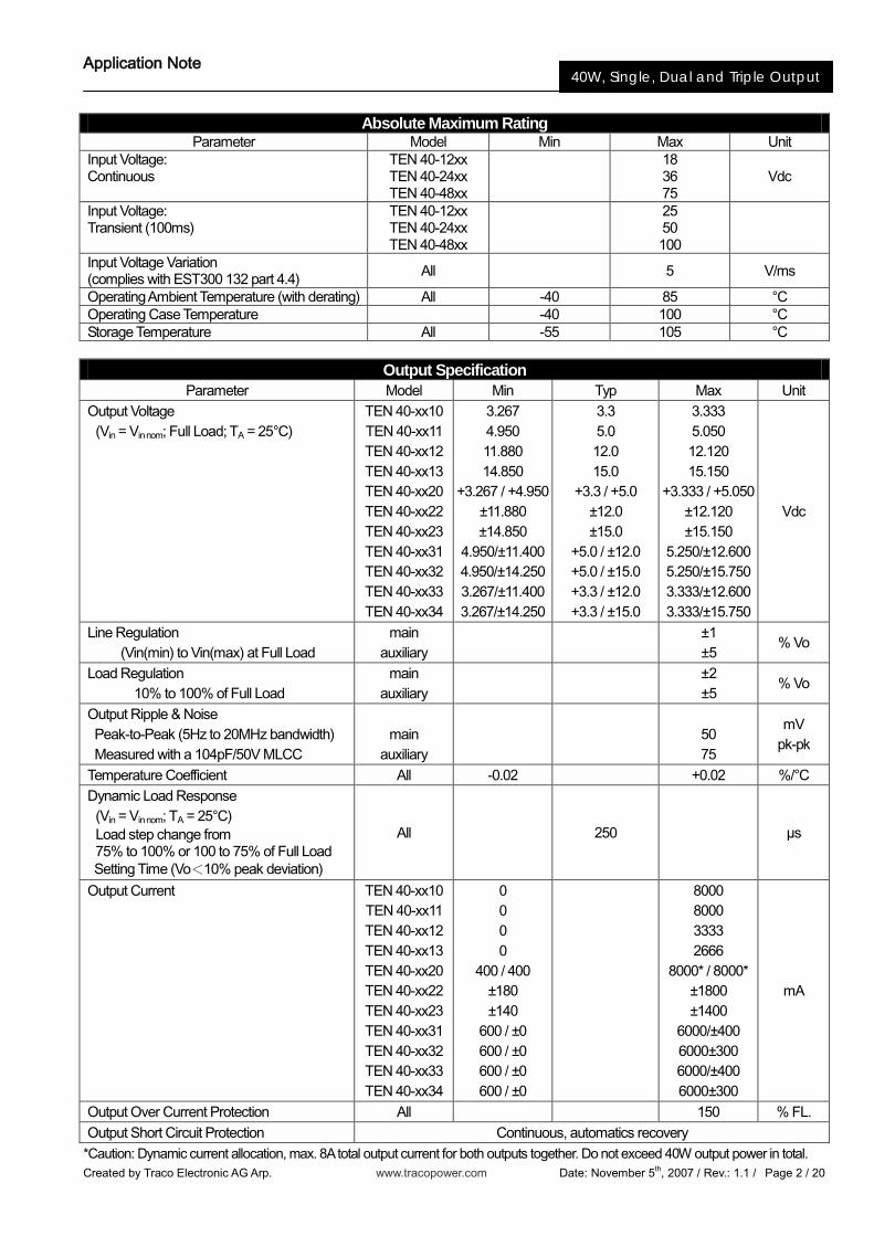
Absolute Maximum Rating
Parameter Model Min Max Unit Input Voltage: Continuous
TEN 40-12xx TEN 40-24xx TEN 40-48xx
18 36 75
Vdc
Input Voltage: Transient (100ms)
TEN 40-12xx TEN 40-24xx TEN 40-48xx
25 50 100
Input Voltage Variation (complies with EST300 132 part 4.4) All 5 V/ms
Operating Ambient Temperature (with derating) All -40 85 °C Operating Case Temperature -40 100 °C Storage Temperature All -55 105 °C
Output Specification Parameter Model Min Typ Max Unit
Output Voltage (Vin = Vin nom; Full Load; TA = 25°C)
TEN 40-xx10 TEN 40-xx11 TEN 40-xx12 TEN 40-xx13 TEN 40-xx20 TEN 40-xx22 TEN 40-xx23 TEN 40-xx31 TEN 40-xx32 TEN 40-xx33 TEN 40-xx34
3.267 4.950 11.880 14.850
+3.267 / +4.950 ±11.880 ±14.850
4.950/±11.400 4.950/±14.250 3.267/±11.400 3.267/±14.250
3.3 5.0 12.0 15.0
+3.3 / +5.0 ±12.0 ±15.0
+5.0 / ±12.0 +5.0 / ±15.0 +3.3 / ±12.0 +3.3 / ±15.0
3.333 5.050 12.120 15.150
+3.333 / +5.050 ±12.120 ±15.150
5.250/±12.600 5.250/±15.750 3.333/±12.600 3.333/±15.750
Vdc
Line Regulation (Vin(min) to Vin(max) at Full Load
main auxiliary
±1 ±5
% Vo
Load Regulation 10% to 100% of Full Load
main auxiliary
±2 ±5
% Vo
Output Ripple & Noise Peak-to-Peak (5Hz to 20MHz bandwidth) Measured with a 104pF/50V MLCC
main
auxiliary
50 75
mV pk-pk
Temperature Coefficient All -0.02 +0.02 %/°C Dynamic Load Response (Vin = Vin nom; TA = 25°C) Load step change from 75% to 100% or 100 to 75% of Full Load Setting Time (Vo<10% peak deviation)
All 250 μs
Output Current TEN 40-xx10 TEN 40-xx11 TEN 40-xx12 TEN 40-xx13 TEN 40-xx20 TEN 40-xx22 TEN 40-xx23 TEN 40-xx31 TEN 40-xx32 TEN 40-xx33 TEN 40-xx34
0 0 0 0
400 / 400 ±180 ±140
600 / ±0 600 / ±0 600 / ±0 600 / ±0
8000 8000 3333 2666
8000* / 8000* ±1800 ±1400
6000/±400 6000±300 6000/±400 6000±300
mA
Output Over Current Protection All 150 % FL. Output Short Circuit Protection Continuous, automatics recovery
*Caution: Dynamic current allocation, max. 8A total output current for both outputs together. Do not exceed 40W output power in total.
Application Note
Created by Traco Electronic AG Arp. www.tracopower.com Date: November 5th, 2007 / Rev.: 1.1 / Page 3 / 20
40W, Single, Dual and Triple Output
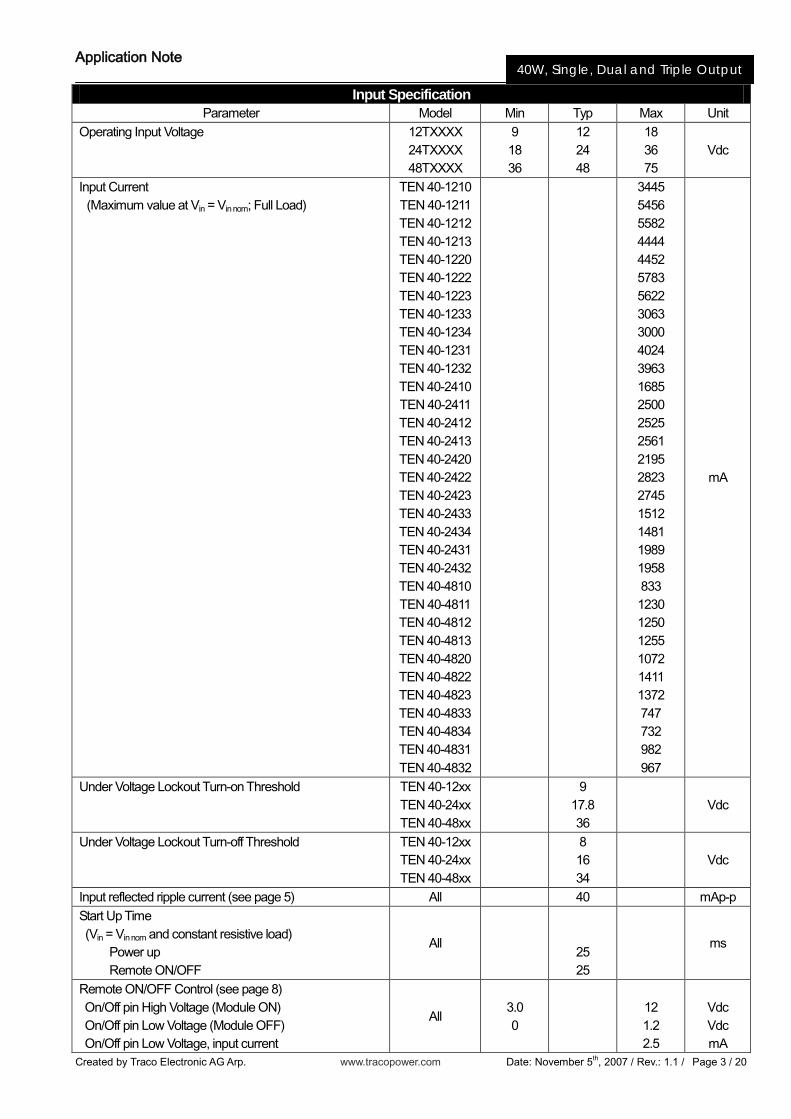
Input Specification Parameter Model Min Typ Max Unit
Operating Input Voltage 12TXXXX 24TXXXX 48TXXXX
9 18 36
12 24 48
18 36 75
Vdc
Input Current (Maximum value at Vin = Vin nom; Full Load)
TEN 40-1210 TEN 40-1211 TEN 40-1212 TEN 40-1213 TEN 40-1220 TEN 40-1222 TEN 40-1223 TEN 40-1233 TEN 40-1234 TEN 40-1231 TEN 40-1232 TEN 40-2410 TEN 40-2411 TEN 40-2412 TEN 40-2413 TEN 40-2420 TEN 40-2422 TEN 40-2423 TEN 40-2433 TEN 40-2434 TEN 40-2431 TEN 40-2432 TEN 40-4810 TEN 40-4811 TEN 40-4812 TEN 40-4813 TEN 40-4820 TEN 40-4822 TEN 40-4823 TEN 40-4833 TEN 40-4834 TEN 40-4831 TEN 40-4832
3445 5456 5582 4444 4452 5783 5622 3063 3000 4024 3963 1685 2500 2525 2561 2195 2823 2745 1512 1481 1989 1958 833 1230 1250 1255 1072 1411 1372 747 732 982 967
mA
Under Voltage Lockout Turn-on Threshold TEN 40-12xx TEN 40-24xx TEN 40-48xx
9
17.8 36
Vdc
Under Voltage Lockout Turn-off Threshold TEN 40-12xx TEN 40-24xx TEN 40-48xx
8 16 34
Vdc
Input reflected ripple current (see page 5) All 40 mAp-p Start Up Time (Vin = Vin nom and constant resistive load) Power up Remote ON/OFF
All
25 25
ms
Remote ON/OFF Control (see page 8) On/Off pin High Voltage (Module ON) On/Off pin Low Voltage (Module OFF) On/Off pin Low Voltage, input current
All 3.0 0
12 1.2 2.5
Vdc Vdc mA
Application Note
Created by Traco Electronic AG Arp. www.tracopower.com Date: November 5th, 2007 / Rev.: 1.1 / Page 4 / 20
40W, Single, Dual and Triple Output
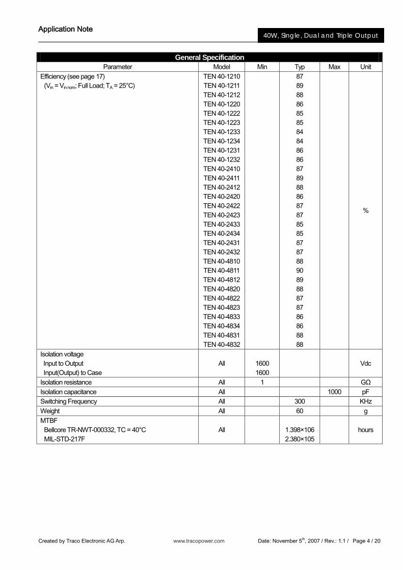
General Specification Parameter Model Min Typ Max Unit
Efficiency (see page 17) (Vin = Vin nom; Full Load; TA = 25°C)
TEN 40-1210 TEN 40-1211 TEN 40-1212 TEN 40-1220 TEN 40-1222 TEN 40-1223 TEN 40-1233 TEN 40-1234 TEN 40-1231 TEN 40-1232 TEN 40-2410 TEN 40-2411 TEN 40-2412 TEN 40-2420 TEN 40-2422 TEN 40-2423 TEN 40-2433 TEN 40-2434 TEN 40-2431 TEN 40-2432 TEN 40-4810 TEN 40-4811 TEN 40-4812 TEN 40-4820 TEN 40-4822 TEN 40-4823 TEN 40-4833 TEN 40-4834 TEN 40-4831 TEN 40-4832
87 89 88 86 85 85 84 84 86 86 87 89 88 86 87 87 85 85 87 87 88 90 89 88 87 87 86 86 88 88
%
Isolation voltage Input to Output Input(Output) to Case
All
1600 1600
Vdc
Isolation resistance All 1 GΩ Isolation capacitance All 1000 pF Switching Frequency All 300 KHz Weight All 60 g MTBF Bellcore TR-NWT-000332, TC = 40°C MIL-STD-217F
All
1.398×10⁶ 2.380×10⁵
hours
Application Note
Created by Traco Electronic AG Arp. www.tracopower.com Date: November 5th, 2007 / Rev.: 1.1 / Page 5 / 20
40W, Single, Dual and Triple Output
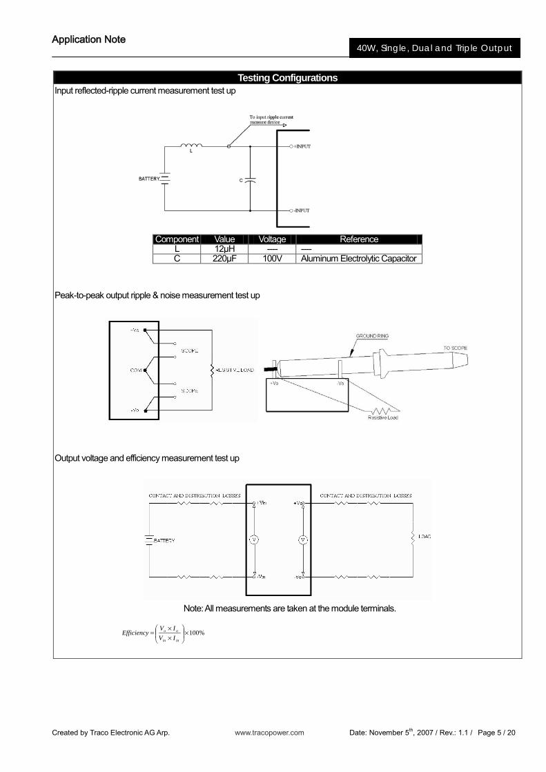
Testing Configurations Input reflected-ripple current measurement test up
Component Value Voltage Reference
L 12μH ---- ---- C 220μF 100V Aluminum Electrolytic Capacitor
Peak-to-peak output ripple & noise measurement test up
Output voltage and efficiency measurement test up
Note: All measurements are taken at the module terminals.
%100×
××
=inin
oo
IVIV
Efficiency
Application Note
Created by Traco Electronic AG Arp. www.tracopower.com Date: November 5th, 2007 / Rev.: 1.1 / Page 6 / 20
40W, Single, Dual and Triple Output
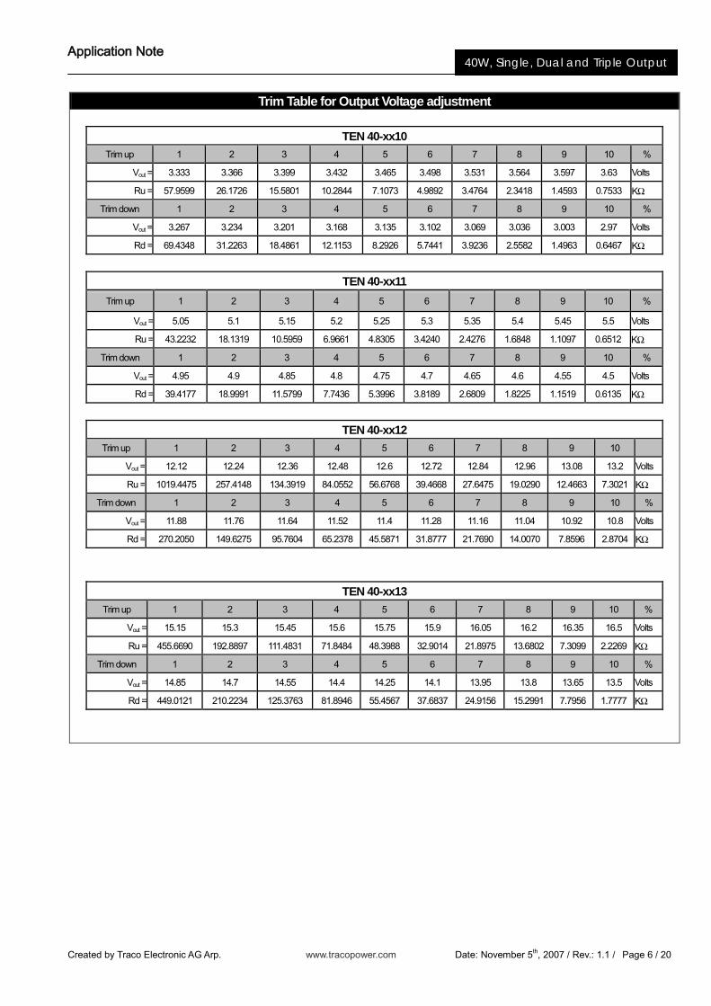
Trim Table for Output Voltage adjustment
TEN 40-xx10 Trim up 1 2 3 4 5 6 7 8 9 10 %
Vout = 3.333 3.366 3.399 3.432 3.465 3.498 3.531 3.564 3.597 3.63 Volts
Ru = 57.9599 26.1726 15.5801 10.2844 7.1073 4.9892 3.4764 2.3418 1.4593 0.7533 KΩ
Trim down 1 2 3 4 5 6 7 8 9 10 %
Vout = 3.267 3.234 3.201 3.168 3.135 3.102 3.069 3.036 3.003 2.97 Volts
Rd = 69.4348 31.2263 18.4861 12.1153 8.2926 5.7441 3.9236 2.5582 1.4963 0.6467 KΩ
TEN 40-xx11
Trim up 1 2 3 4 5 6 7 8 9 10 %
Vout = 5.05 5.1 5.15 5.2 5.25 5.3 5.35 5.4 5.45 5.5 Volts
Ru = 43.2232 18.1319 10.5959 6.9661 4.8305 3.4240 2.4276 1.6848 1.1097 0.6512 KΩ
Trim down 1 2 3 4 5 6 7 8 9 10 %
Vout = 4.95 4.9 4.85 4.8 4.75 4.7 4.65 4.6 4.55 4.5 Volts
Rd = 39.4177 18.9991 11.5799 7.7436 5.3996 3.8189 2.6809 1.8225 1.1519 0.6135 KΩ
TEN 40-xx12 Trim up 1 2 3 4 5 6 7 8 9 10
Vout = 12.12 12.24 12.36 12.48 12.6 12.72 12.84 12.96 13.08 13.2 Volts
Ru = 1019.4475 257.4148 134.3919 84.0552 56.6768 39.4668 27.6475 19.0290 12.4663 7.3021 KΩ
Trim down 1 2 3 4 5 6 7 8 9 10 %
Vout = 11.88 11.76 11.64 11.52 11.4 11.28 11.16 11.04 10.92 10.8 Volts
Rd = 270.2050 149.6275 95.7604 65.2378 45.5871 31.8777 21.7690 14.0070 7.8596 2.8704 KΩ
TEN 40-xx13
Trim up 1 2 3 4 5 6 7 8 9 10 %
Vout = 15.15 15.3 15.45 15.6 15.75 15.9 16.05 16.2 16.35 16.5 Volts
Ru = 455.6690 192.8897 111.4831 71.8484 48.3988 32.9014 21.8975 13.6802 7.3099 2.2269 KΩ
Trim down 1 2 3 4 5 6 7 8 9 10 %
Vout = 14.85 14.7 14.55 14.4 14.25 14.1 13.95 13.8 13.65 13.5 Volts
Rd = 449.0121 210.2234 125.3763 81.8946 55.4567 37.6837 24.9156 15.2991 7.7956 1.7777 KΩ
Application Note
Created by Traco Electronic AG Arp. www.tracopower.com Date: November 5th, 2007 / Rev.: 1.1 / Page 7 / 20
40W, Single, Dual and Triple Output
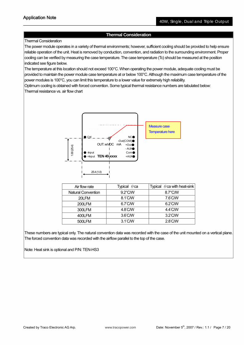
Thermal Consideration Thermal Consideration The power module operates in a variety of thermal environments; however, sufficient cooling should be provided to help ensure reliable operation of the unit. Heat is removed by conduction, convention, and radiation to the surrounding environment. Proper cooling can be verified by measuring the case temperature. The case temperature (Tc) should be measured at the position indicated see figure below. The temperature at this location should not exceed 100°C. When operating the power module, adequate cooling must be provided to maintain the power module case temperature at or below 100°C. Although the maximum case temperature of the power modules is 100°C, you can limit this temperature to a lower value for extremely high reliability. Optimum cooling is obtained with forced convention. Some typical thermal resistance numbers are tabulated below: Thermal resistance vs. air flow chart
Air flow rate Typical θca Typical θca with heat-sink
Natural Convention 9.2°C/W 8.7°C/W 20LFM 8.1°C/W 7.6°C/W
200LFM 6.7°C/W 6.2°C/W
300LFM 4.8°C/W 4.4°C/W
400LFM 3.6°C/W 3.2°C/W
500LFM 3.1°C/W 2.8°C/W
These numbers are typical only. The natural convention data was recorded with the case of the unit mounted on a vertical plane. The forced convention data was recorded with the airflow parallel to the top of the case. Note: Heat sink is optional and P/N: TEN-HS3
POWER MATE TECHNOLOGY CO., LTD
Ctrl NC -Out(COM) +Out - AUX -Input Com +Input +AUX
TEN 40-xxxx
OUT: xxVDC mA
Measure case
Temperature here
1.00
(25.
4)
25.4 (1.0)

Application Note
Created by Traco Electronic AG Arp. www.tracopower.com Date: November 5th, 2007 / Rev.: 1.1 / Page 8 / 20
40W, Single, Dual and Triple Output
Output over current protection When excessive output currents occur in the system, circuit protection is required on all power supplies. Normally, overload current is maintained at approximately 115~150 percent of rated current for TEN 40. Hiccup-mode is a method of operation in a power supply whose purpose is to protect the power supply from being damaged during an over-current fault condition. It also enables the power supply to restart when the fault is removed. There are other ways of protecting the power supply when it is over-loaded, such as the maximum current limiting or current foldback methods. One of the problems resulting from over current is that excessive heat may be generated in power devices; especially MOSFET and Shottky diodes and the temperature of those devices may exceed their specified limits. A protection mechanism has to be used to prevent those power devices from being damaged. The operation of hiccup is as follows. When the current sense circuit sees an over-current event, the controller shuts off the power supply for a given time and then tries to start up the power supply again. If the over-load condition has been removed, the power supply will start up and operate normally; otherwise, the controller will see another over-current event and shut off the power supply again, repeating the previous cycle. Hiccup operation has none of the drawbacks of the other two protection methods, although its circuit is more complicated because it requires a timing circuit. The excess heat due to overload lasts for only a short duration in the hiccup cycle, hence the junction temperature of the power devices is much lower. The hiccup operation can be done in various ways. For example, one can start hiccup operation any time an over-current event is detected; or prohibit hiccup during a designated start-up is usually larger than during normal operation and it is easier for an over-current event is detected; or prohibit hiccup during a designated start-up interval (usually a few milliseconds). The reason for the latter operation is that during start-up, the power supply needs to provide extra current to charge up the output capacitor. Thus the current demand during start-up is usually larger than during normal operation and it is easier for an over-current event to occur. If the power supply starts to hiccup once there is an over-current, it might never start up successfully. Hiccup mode protection will give the best protection for a power supply against over current situations, since it will limit the average current to the load at a low level, so reducing power dissipation and case temperature in the power devices.
Short Circuitry Protection Continuous, hiccup and auto-recovery mode. During short circuit, converter still shut down. The average current during this condition will be very low and the device can be safety in this condition.
Input Source Impedance The power module should be connected to a low impedance input source. Highly inductive source impedance can affect the stability of the power module. Input external L-C filter is recommended to minimize input reflected ripple current. The inductor is simulated source impedance of 12μH and capacitor is Nippon chemi-con KZE series 47μF/100V. The capacitor must as close as possible to the input terminals of the power module for lower impedance.
Over Temperature Protection The power modules operate in a variety of thermal environments; However, sufficient cooling should always be provided to help ensure reliable operation. The over-temperature protection consists of circuitry that provides protection from thermal damage. If the temperature exceeds the over-temperature Threshold the module will shut down. For reliable operation this temperature should not exceed 100 the output power of the module should not exceed the rated power of the module
Application Note
Created by Traco Electronic AG Arp. www.tracopower.com Date: November 5th, 2007 / Rev.: 1.1 / Page 9 / 20
40W, Single, Dual and Triple Output
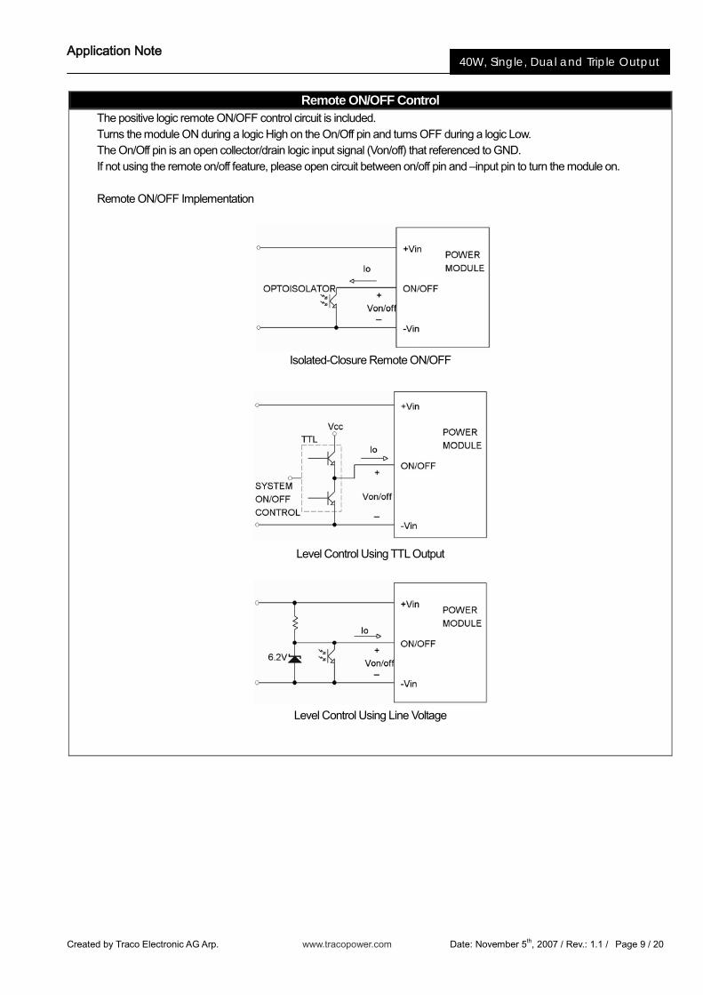
Remote ON/OFF Control The positive logic remote ON/OFF control circuit is included. Turns the module ON during a logic High on the On/Off pin and turns OFF during a logic Low. The On/Off pin is an open collector/drain logic input signal (Von/off) that referenced to GND. If not using the remote on/off feature, please open circuit between on/off pin and –input pin to turn the module on. Remote ON/OFF Implementation
Isolated-Closure Remote ON/OFF
Level Control Using TTL Output
Level Control Using Line Voltage
Application Note
Created by Traco Electronic AG Arp. www.tracopower.com Date: November 5th, 2007 / Rev.: 1.1 / Page 10 / 20
40W, Single, Dual and Triple Output
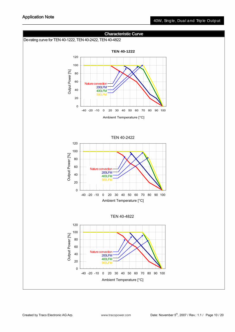
Characteristic Curve De-rating curve for TEN 40-1222, TEN 40-2422, TEN 40-4822
TEN 40-1222
0
20
40
60
80
100
120
-40 -20 -10 0 20 30 40 50 60 70 80 90 100
Ambient Temperature [°C]
Out
put P
ower
[%]
TEN 40-2422
0
20
40
60
80
100
120
-40 -20 -10 0 20 30 40 50 60 70 80 90 100
Ambient Temperature [°C]
Out
put P
ower
[%]
TEN 40-4822
0
20
40
60
80
100
120
-40 -20 -10 0 20 30 40 50 60 70 80 90 100
Ambient Temperature [°C]
Out
put P
ower
[%]
Nature convection 200LFM 400LFM 500LFM
Nature convection 200LFM 400LFM 500LFM
Nature convection 200LFM 400LFM 500LFM
Application Note
Created by Traco Electronic AG Arp. www.tracopower.com Date: November 5th, 2007 / Rev.: 1.1 / Page 11 / 20
40W, Single, Dual and Triple Output
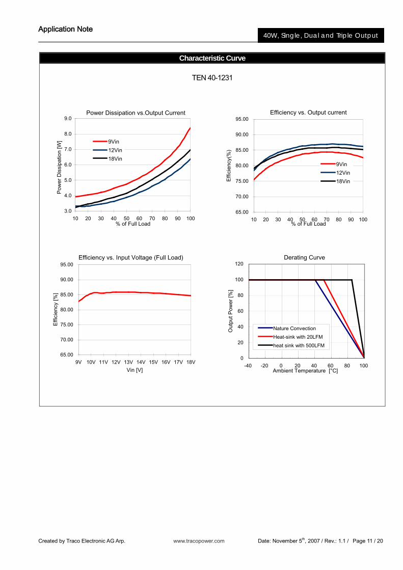
Efficiency vs. Output current
65.00
70.00
75.00
80.00
85.00
90.00
95.00
10 20 30 40 50 60 70 80 90 100% of Full Load
Effi
cien
cy(%
)
9Vin
12Vin
18Vin
Characteristic Curve
TEN 40-1231
Power Dissipation vs.Output Current
3.0
4.0
5.0
6.0
7.0
8.0
9.0
10 20 30 40 50 60 70 80 90 100% of Full Load
Pow
er D
issi
patio
n [W
] 9Vin
12Vin
18Vin
Efficiency vs. Input Voltage (Full Load)
65.00
70.00
75.00
80.00
85.00
90.00
95.00
9V 10V 11V 12V 13V 14V 15V 16V 17V 18V
Vin [V]
Effi
cien
cy [%
]
Derating Curve
0
20
40
60
80
100
120
-40 -20 0 20 40 60 80 100Ambient Temperature [°C]
Out
put P
ower
[%]
Nature Convection
Heat-sink with 20LFM
heat sink with 500LFM
Application Note
Created by Traco Electronic AG Arp. www.tracopower.com Date: November 5th, 2007 / Rev.: 1.1 / Page 12 / 20
40W, Single, Dual and Triple Output
Characteristic Curve
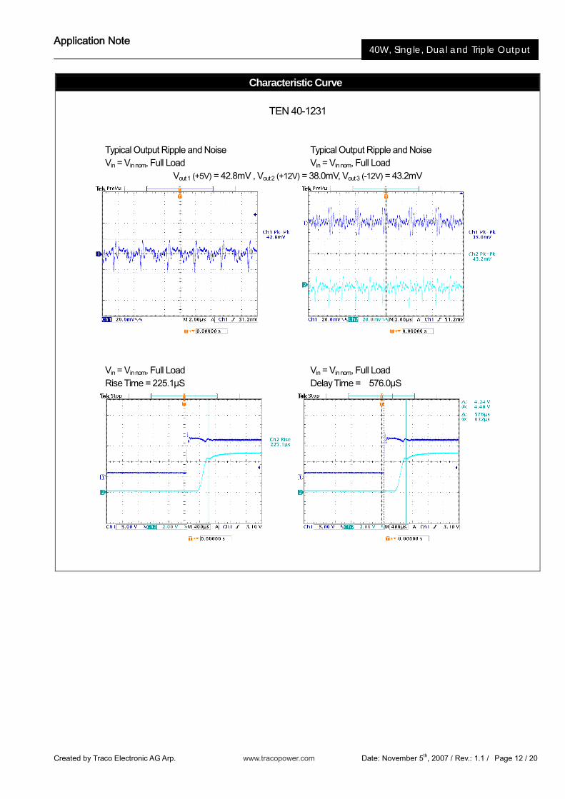
TEN 40-1231
Typical Output Ripple and Noise Typical Output Ripple and Noise Vin = Vin nom, Full Load Vin = Vin nom, Full Load
Vout 1 (+5V) = 42.8mV , Vout 2 (+12V) = 38.0mV, Vout 3 (-12V) = 43.2mV
Vin = Vin nom, Full Load Vin = Vin nom, Full Load Rise Time = 225.1µS Delay Time = 576.0µS
Application Note
Created by Traco Electronic AG Arp. www.tracopower.com Date: November 5th, 2007 / Rev.: 1.1 / Page 13 / 20
40W, Single, Dual and Triple Output
Characteristic Curve
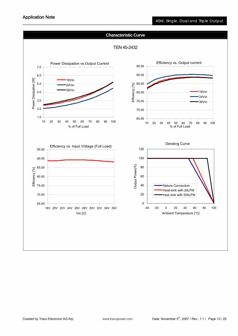
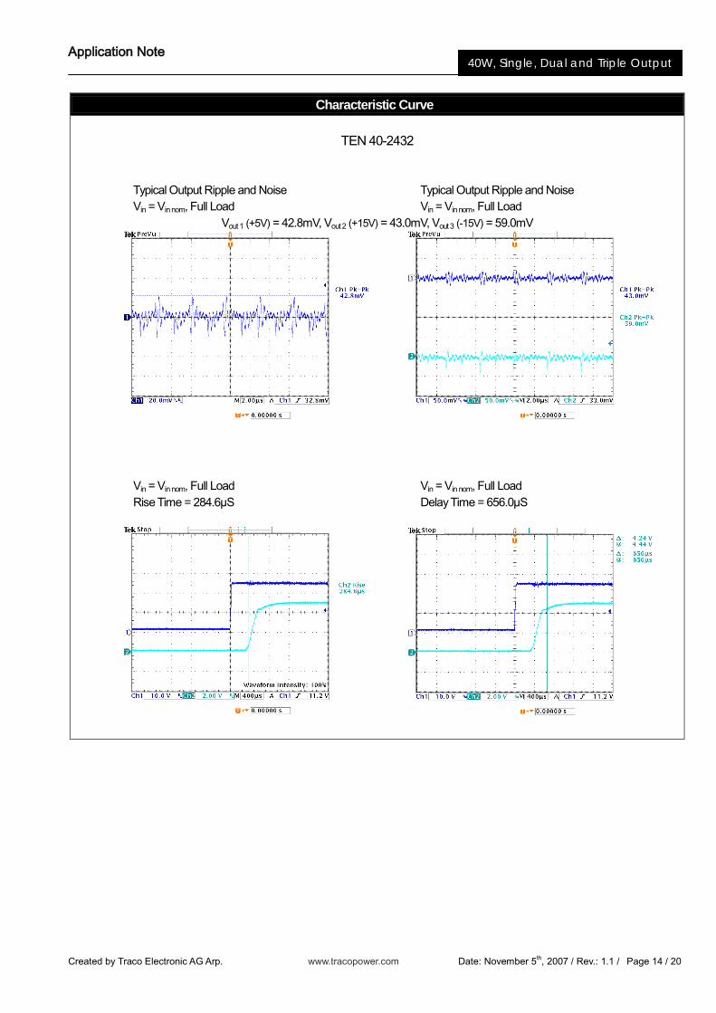
TEN 40-2432
Efficiency vs. Output current
65.00
70.00
75.00
80.00
85.00
90.00
95.00
10 20 30 40 50 60 70 80 90 100% of Full Load
Effi
cien
cy [%
]
18Vin
24Vin
36Vin
Power Dissipation vs.Output Current
1.0
2.0
3.0
4.0
5.0
6.0
7.0
10 20 30 40 50 60 70 80 90 100
% of Full Load
Pow
er D
issi
patio
n [W
]
18Vin
24Vin
36Vin
Efficiency vs. Input Voltage (Full Load)
65.00
70.00
75.00
80.00
85.00
90.00
95.00
18V 20V 22V 24V 26V 28V 30V 32V 34V 36V
Vin [V]
Effi
cien
cy [%
]
Derating Curve
0
20
40
60
80
100
120
-40 -20 0 20 40 60 80 100
Ambient Temperature [°C]
Out
put P
ower
(%)
Nature ConvectionHeat-sink with 20LFMheat sink with 500LFM
Application Note
Created by Traco Electronic AG Arp. www.tracopower.com Date: November 5th, 2007 / Rev.: 1.1 / Page 14 / 20
40W, Single, Dual and Triple Output
Characteristic Curve
TEN 40-2432
Typical Output Ripple and Noise Typical Output Ripple and Noise Vin = Vin nom, Full Load Vin = Vin nom, Full Load
Vout 1 (+5V) = 42.8mV, Vout 2 (+15V) = 43.0mV, Vout 3 (-15V) = 59.0mV
Vin = Vin nom, Full Load Vin = Vin nom, Full Load Rise Time = 284.6µS Delay Time = 656.0µS
Application Note
Created by Traco Electronic AG Arp. www.tracopower.com Date: November 5th, 2007 / Rev.: 1.1 / Page 15 / 20
40W, Single, Dual and Triple Output
Characteristic Curve
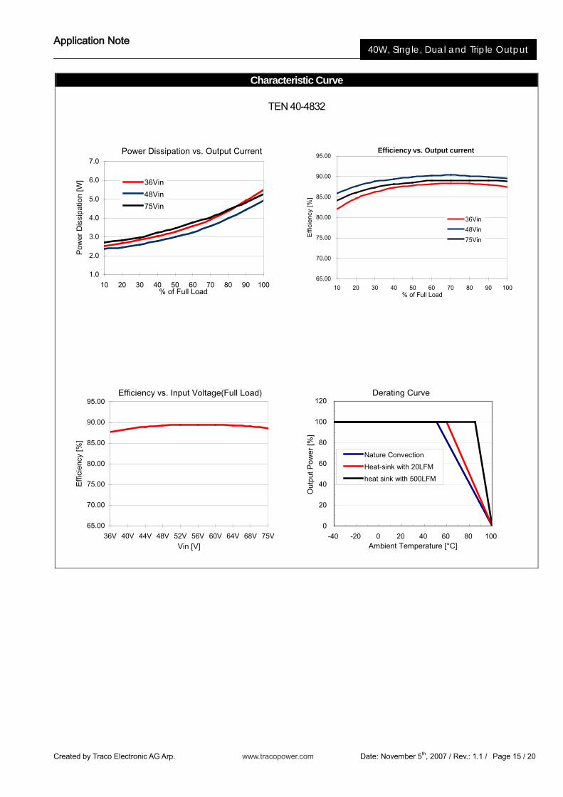
TEN 40-4832
Power Dissipation vs. Output Current
1.0
2.0
3.0
4.0
5.0
6.0
7.0
10 20 30 40 50 60 70 80 90 100% of Full Load
Pow
er D
issi
patio
n [W
] 36Vin
48Vin
75Vin
Efficiency vs. Output current
65.00
70.00
75.00
80.00
85.00
90.00
95.00
10 20 30 40 50 60 70 80 90 100% of Full Load
Eff
icie
ncy
[%]
36Vin
48Vin
75Vin
Efficiency vs. Input Voltage(Full Load)
65.00
70.00
75.00
80.00
85.00
90.00
95.00
36V 40V 44V 48V 52V 56V 60V 64V 68V 75VVin [V]
Effi
cien
cy [%
]
Derating Curve
0
20
40
60
80
100
120
-40 -20 0 20 40 60 80 100Ambient Temperature [°C]
Out
put P
ower
[%]
Nature Convection
Heat-sink with 20LFM
heat sink with 500LFM
Application Note
Created by Traco Electronic AG Arp. www.tracopower.com Date: November 5th, 2007 / Rev.: 1.1 / Page 16 / 20
40W, Single, Dual and Triple Output
Characteristic Curve
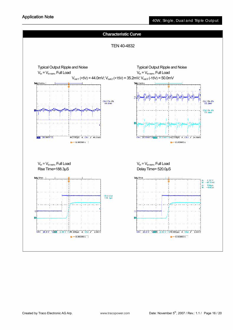
TEN 40-4832
Typical Output Ripple and Noise Typical Output Ripple and Noise Vin = Vin nom, Full Load Vin = Vin nom, Full Load
Vout 1 (+5V) = 44.0mV; Vout 2 (+15V) = 35.2mV; Vout 3 (-15V) = 50.0mV
Vin = Vin nom, Full Load Vin = Vin nom, Full Load Rise Time=188.3µS Delay Time= 520.0µS
Application Note
Created by Traco Electronic AG Arp. www.tracopower.com Date: November 5th, 2007 / Rev.: 1.1 / Page 17 / 20
40W, Single, Dual and Triple Output
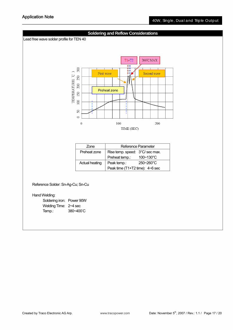
Soldering and Reflow Considerations Lead free wave solder profile for TEN 40
Zone Reference Parameter Preheat zone Rise temp. speed: 3°C/ sec max.
Preheat temp.: 100~130°C Actual heating Peak temp.: 250~260°C
Peak time (T1+T2 time): 4~6 sec Reference Solder: Sn-Ag-Cu; Sn-Cu Hand Welding: Soldering iron: Power 90W Welding Time: 2~4 sec Temp.: 380~400°C
Application Note
Created by Traco Electronic AG Arp. www.tracopower.com Date: November 5th, 2007 / Rev.: 1.1 / Page 18 / 20
40W, Single, Dual and Triple Output
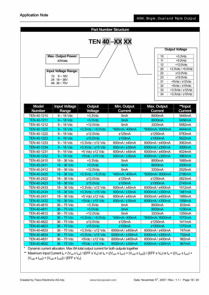
Part Number Structure
TEN 40 –XX XX
* Dynamic current allocation. Max 8A total output current for both outputs together ** Maximum Input Current IIn = (Vout x Iout) / (EFF x VIn) or IIn = ((Vout1 x Iout1) + (Vout2 x Iout2)) / (EFF x VIn) or IIn = ((Vout1 x Iout1) +
(Vout2 x Iout2) + (Vout3 x Iout3)) / (EFF x VIn)
Model Number
Input Voltage Range
Output Voltage
Min. Output Current
Max. Output Current
**Input Current
TEN 40-1210 9 – 18 Vdc +3.3Vdc 0mA 8000mA 3445mA TEN 40-1211 9 – 18 Vdc +5.0Vdc 0mA 8000mA 5456mA TEN 40-1212 9 – 18 Vdc +12.0Vdc 0mA 3333mA 5582mA TEN 40-1220 9 – 18 Vdc +3.3Vdc / +5.0Vdc *400mA / 400mA *8000mA / 8000mA 4444mA TEN 40-1222 9 – 18 Vdc ±12.0Vdc ±125mA ±1250mA 5783mA TEN 40-1223 9 – 18 Vdc ±15.0Vdc ±100mA ±1000mA 5622mA TEN 40-1233 9 – 18 Vdc +3.3Vdc / ±12 Vdc 600mA / ±40mA 6000mA / ±400mA 3063mA TEN 40-1234 9 – 18 Vdc +3.3Vdc / ±15 Vdc 600mA / ±30mA 6000mA / ±300mA 3000mA TEN 40-1231 9 – 18 Vdc +5 Vdc/ ±12 Vdc 600mA / ±40mA 6000mA / ±400mA 4024mA TEN 40-1232 9 – 18 Vdc +5Vdc / ±15 Vdc 600mA / ±30mA 6000mA / ±300mA 3963mA TEN 40-2410 18 – 36 Vdc +3.3Vdc 0mA 8000mA 1685mA TEN 40-2411 18 – 36 Vdc +5.0Vdc 0mA 8000mA 2500mA TEN 40-2412 18 – 36 Vdc +12.0Vdc 0mA 3333mA 2525mA TEN 40-2420 18 – 36 Vdc +3.3Vdc / +5.0Vdc *400mA / 400mA *8000mA / 8000mA 2195mA TEN 40-2422 18 – 36 Vdc ±12.0Vdc ±125mA ±1250mA 2823mA TEN 40-2423 18 – 36 Vdc ±15.0Vdc ±100mA ±1000mA 2745mA TEN 40-2433 18 – 36 Vdc +3.3Vdc / ±12 Vdc 600mA / ±40mA 6000mA / ±400mA 1512mA TEN 40-2434 18 – 36 Vdc +3.3Vdc / ±15 Vdc 600mA / ±30mA 6000mA / ±300mA 1481mA TEN 40-2431 18 – 36 Vdc +5 Vdc/ ±12 Vdc 600mA / ±40mA 6000mA / ±400mA 1989mA TEN 40-2432 18 – 36 Vdc +5Vdc / ±15 Vdc 600mA / ±30mA 6000mA / ±300mA 1958mA TEN 40-4810 36 – 75 Vdc +3.3Vdc 0mA 8000mA 833mA TEN 40-4811 36 – 75 Vdc +5.0Vdc 0mA 8000mA 1230mA TEN 40-4812 36 – 75 Vdc +12.0Vdc 0mA 3333mA 1250mA TEN 40-4820 36 – 75 Vdc +3.3Vdc / +5.0Vdc *400mA / 400mA *8000mA / 8000mA 1072mA TEN 40-4822 36 – 75 Vdc ±12.0Vdc ±125mA ±1250mA 1411mA TEN 40-4823 36 – 75 Vdc ±15.0Vdc ±100mA ±1000mA 1372mA TEN 40-4833 36 – 75 Vdc +3.3Vdc / ±12 Vdc 6000mA / ±400mA 6000mA / ±400mA 747mA TEN 40-4834 36 – 75 Vdc +3.3Vdc / ±15 Vdc 6000mA / ±300mA 6000mA / ±300mA 732mA TEN 40-4831 36 – 75 Vdc +5Vdc / ±12 Vdc 6000mA / ±400mA 6000mA / ±400mA 982mA TEN 40-4832 36 – 75 Vdc +5Vdc / ±15 Vdc 6000mA / ±300mA 6000mA / ±300mA 967mA
Input Voltage Range:
12: 9 ~ 18V 24: 18 ~ 36V 48: 36 ~ 75V
Max. Output Power: 40Watts
Output Voltage
10 : +3.3Vdc 11 : +5.0Vdc 12 : +12.0Vdc 20 : +3.3Vdc / +5.0Vdc 22 : ±12.0Vdc 23 : ±15.0Vdc 31 : +5Vdc / ±12Vdc 32 : +5Vdc / ±15Vdc 33 : +3.3Vdc / ±12Vdc 34 : +3.3Vdc / ±15Vdc
Application Note
Created by Traco Electronic AG Arp. www.tracopower.com Date: November 5th, 2007 / Rev.: 1.1 / Page 19 / 20
40W, Single, Dual and Triple Output
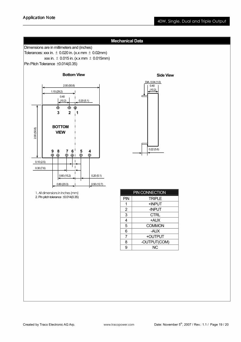
Mechanical DataDimensions are in millimeters and (inches)Tolerances: xxx in. ± 0.020 in. (x.x mm ± 0.02mm) xxx in. ± 0.015 in. (x.x mm ± 0.015mm)Pin Pitch Tolerance ±0.014(0.35)
Side View
Bottom View
PIN CONNECTIONPIN TRIPLE1 +INPUT2 -INPUT3 CTRL4 +AUX5 COMMON6 -AUX7 +OUTPUT8 -OUTPUT(COM)9 NC
1
2.00 (50.8)
0.40(10.2) 0.20 (5.1)
2.00
(50.
8)
0.80 (20.3)
0.60 (15.2)
0.30 (7.6)
0.10 (2.5)
0.50 (12.7)
0.20 (5.1)
4
3 2
8 7 6 59
1. All dimensions in Inches (mm)2. Pin pitch tolerance ±0.014(0.35)
1.15 (29.2)
BOTTOMVIEW
0.40(10.2)
0.22 (5.6)
DIA. 0.04 (1.0)
Application Note
Created by Traco Electronic AG Arp. www.tracopower.com Date: November 5th, 2007 / Rev.: 1.1 / Page 20 / 20
40W, Single, Dual and Triple Output
Safety and Installation Instruction Isolation consideration The TEN 40 series features 1.6k Volt DC isolation from input to output, input to case, and output to case. The input to output resistance is greater than 109 megohms. Nevertheless, if the system using the power module needs to receive safety agency approval, certain rules must be followed in the design of the system using the model. In particular, all of the creepage and clearance requirements of the end-use safety requirement must be observed. These documents include UL-1950, EN60950 and CSA 22.2-950, although specific applications may have other or additional requirements. Fusing Consideration Caution: This power module is not internally fused. An input line fuse must always be used. This encapsulated power module can be used in a wide variety of applications, ranging from simple stand-alone operation to an integrated part of a sophisticated power architecture. To maximum flexibility, internal fusing is not included; however, to achieve maximum safety and system protection, always use an input line fuse. The safety agencies require a normal-blow fuse with maximum rating of 5 A. Based on the information provided in this data sheet on inrush energy and maximum dc input current, the same type of fuse with lower rating can be used. Refer to the fuse manufacturer’s data for further information.
MTBF and Reliability The MTBF of TEN 40 series of DC/DC converters has been calculated using The MTBF of TEN 40 series of DC/DC converters has been calculated using 1. MIL-HDBK-217F under the following conditions:
Nominal Input Voltage Iout = Iout max TA = 25°C
The resulting figure for MTBF is 292’400 hours single and dual output. The resulting figure for MTBF is 364’600 hours triple output.
2. Bellcore TR-NWT-000332 Case I: 50% stress, Operating Temperature at 40°C (Ground fixed and controlled environment) The resulting figure for MTBF is 1’398’000 hours.


![Danse macabre [Op.40] - Free-scores.com · Op. 40 Mouvement PIANO. DANSE MACABRE ten Transcription par H. CRAMER modere de Valse PPP ten. Tous droits d'exécution réser.t'ãs. A](https://img.pdfslide.us/doc/110x75/60ea0098d5aa3710f9524030/danse-macabre-op40-free-op-40-mouvement-piano-danse-macabre-ten-transcription.jpg)