Embed Size (px)
Citation preview
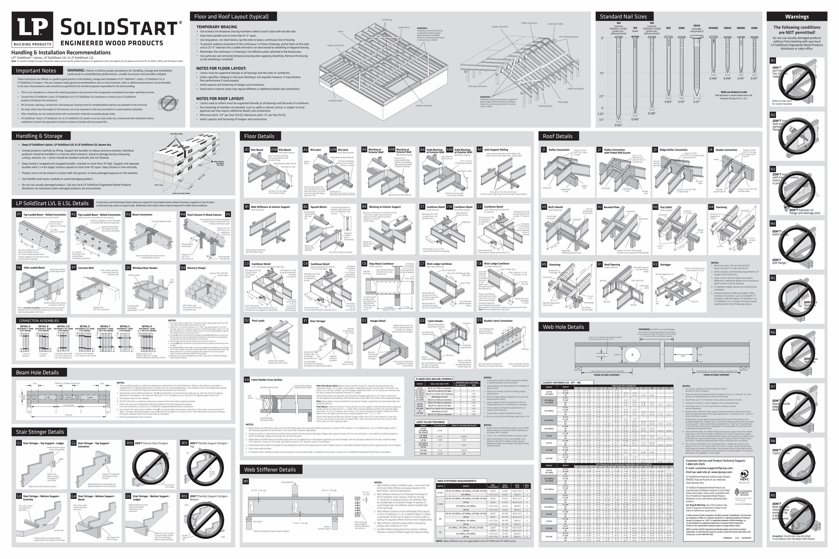
Floor and Roof Layout (typical) Warnings
Important Notes These instructions are offered as a guide to good practice in the handling, storage and installation of LP® SolidStart® I-Joists, LP SolidStart LVL & LP SolidStart LSL beams. They are, however, solely general recommendations and, in some instances, other or additional precautions may be desirable. In all cases, the procedures used should be as specified by the architect/engineer responsible for the entire building.
• This is not intended as a manual for selecting products and assumes that components and details have been specified correctly.
• Consult the LP SolidStart I-Joist, LP SolidStart LVL & LP SolidStart LSL brochures or contact your LP SolidStart products distributor for assistance.
• All rim joists, blocking, connections and temporary bracing must be installed before erectors are allowed on the structure.
• No loads other than the weight of the erectors are to be imposed on the structure before it is permanently sheathed.
• After sheathing, do not overload joists with construction materials exceeding design loads.
• LP SolidStart I-Joists, LP SolidStart LVL & LP SolidStart LSL beams must be used under dry, covered and well ventilated interior conditions in which the equivalent moisture content in lumber will not exceed 16%.
Handling & Installation Recommendations LP® SolidStart® I-Joists, LP SolidStart LVL & LP SolidStart LSLNote: For specific strength and span information, please consult specific product brochures. For applications with I-Joist depths over 16, " please consult the LPI® 36, 42Plus, 52Plus and 56 Product Guides.
The following conditions are NOT permitted!
Do not use visually damaged products without first checking with your local
LP SolidStart Engineered Wood Products distributor or sales office.
WARNING: Failure to follow proper procedures for handling, storage and installation could result in unsatisfactory performance, unsafe structures and possible collapse.
Standard Nail Sizes
TEMPORARY BRACING• Use at least 1x4 temporary bracing members nailed to each I-Joist with two 8d nails.• Keep them parallel and no more than 8'-0" apart.• Use long pieces, not short blocks; lap the ends to keep a continuous line of bracing.• To prevent endwise movement of the continuous 1 x 4 lines of bracing, anchor them at the ends
and at 25'-0" intervals into a stable end wall or an area braced by sheathing or diagonal bracing.• Remember, the continuous 1 x 4 bracing is not effective unless attached to the braced area.• Use particular care removing temporary bracing when applying sheathing. Remove the bracing
as the sheathing is attached.
NOTES FOR FLOOR LAYOUT:• I-Joists must be supported laterally at all bearings and the ends of cantilevers.• Unless specified, bridging or mid-span blocking is not required; however, it may enhance
floor performance if used properly.• Verify capacity and fastening of hangers and connectors.• Some wind or seismic loads may require different or additional details and connections.
NOTES FOR ROOF LAYOUT:• I-Joists used as rafters must be supported laterally at all bearings and the ends of cantilevers.• Any fastening of member not detailed, such as uplift or seismic anchor, is subject to local
approval and may require additional details and connections.• Minimum pitch: 1/4" per foot (1/4:12). Maximum pitch: 12" per foot (12:12).• Verify capacity and fastening of hangers and connections.
Hanger connections
I-JoistsWARNING:Temporary construction bracing is required for lateral support before decking is completed. Failure to use bracing could result in serious injury or death.
LPI blocking
Squash blocks
Hanger connections
Cantilever details
Hanger connections
LPI or blocking panels
Rafter connections Connection of plies
Post-beam connectionRafter seat details
Roof header
Overhang details
WARNING:Temporary construction bracing is required for lateral support before decking is completed. Failure to use bracing could result in serious injury or death.
Connections and fastenings shown below are typical for top loaded beams (where framing is applied on top of beam so that each ply carries an equal load). Additional nails and/or bolts may be required for other load conditions.LP SolidStart LVL & LSL Details
Stair Stringer Details
Web Stiffener Details
DON’T make hole with hammer unless knock-out is provided.
DON’T hammer on flange and damage joist.
R3
DON’T overcut hole anddamage flange.
R2
Refer to hole chart for correct location.
R1
DON’T put holes too close to supports.
DON’T support I-Joist on web.
R8
DON’T cut beyond inside edge of bearing.
R7
DON’T use 16d nails.
R6
R5
DON’T cut flange for pipes.
Handling & Storage • Keep LP SolidStart I-Joists, LP SolidStart LVL & LP SolidStart LSL beams dry.
• Unload products carefully by lifting. Support the bundles to reduce excessive bowing. Individual products should be handled in a manner which prevents physical damage during measuring, cutting, erection, etc. I-Joists should be handled vertically and not flatwise.
• Keep stored in wrapped and strapped bundles, stacked no more than 10' high. Support and separate bundles with 2 x 4 (or larger) stickers spaced no more than 10' apart. Keep stickers in line vertically.
• Product must not be stored in contact with the ground, or have prolonged exposure to the weather.
• Use forklifts and cranes carefully to avoid damaging product.
• Do not use visually damaged product. Call your local LP SolidStart Engineered Wood Products distributor for assistance when damaged products are encountered.
Roof Details
Roof OpeningHanger connections
Filler on back sideWeb filler
Web stiffener required (see Web Stiffener
details)
Filler block
K1
Web filler
Install header plumb
NOTES:1. Minimum pitch: 1/4" per foot (1/4:12).
Maximum pitch: 12" per foot (12:12).2. Verify capacity and fastening requirements of
hangers and connectors.3. Some wind or seismic loads may require
different or additional details and connections. Uplift anchors may be required.
4. 4" diameter hole(s) may be cut in blocking for ventilation.
5. Lateral resistance shall be provided. Other methods of restraint, such as full depth LP SolidStart OSB Rim Board, LP SolidStart LVL, LP SolidStart LSL or metal X-bracing may be substituted for the LPI blocking shown.
Overhang
Web fillers required both sides of I-Joist
2'-0"
max.
8d nails at 6" oc 1" from edge
LPI blocking5
4'-0" m
in.
8d or 10d box toe-nail to plate
2 x 4 cut to fit
H5
Beveled plate
Outrigger
8d nails staggered at 6" oc
2 x 4 filler
Gable end
Maximum overhang same as rafter spacing (2'-0" max.)
K2
Ladder
Rafter Connection with Fitted OSB Gusset
23/32" x 2'–0" OSB with 8–16d nails each side min. 1/8" gap at top
Beveled plate
LPI blocking5Support beam
or wall
J2Rafter Connection Simpson® LSTA24, USP® LSTI-22 strap (or equal)
Beveled plateLPI blocking5
Support beam or wall
J1 Ridge Rafter ConnectionSimpson® LSTA24, USP® LSTI-22 strap (or equal) for pitch over 7:12
Web filler required each side
Simpson® LSSU, USP® TMU (or equal) hanger
Structural beam
J3 Header Connection
Header
Simpson® LSTA24, USP® LSTI-22 strap (or equal) for pitch over 7:12
Web fillerrequired each side
Simpson® LSSU, USP® TMU (or equal) hanger
J4
Beveled Plate
2 x beveled plate
Simpson® VPA, USP® TMP (or equal) connector may be substituted for beveled plate
LPI blocking5
H2 Overhang
2 x 4 filler
8d nails at 6" oc staggered and clinched
2 x 4 cutto fit both sides
2'-0"
max.
4'-0" m
in
LPI blocking5
H4
Beveled web stiffenersrequired both sides
Don’t cut beyond inside
face of bearing
LPI blocking5
Cut to fit tight to wall plate
Bird’s Mouth(lower bearing only)
H1
2'-0" max.
2'-0" max.
Beveled plate
Flat Soffit (Fascia support) 8d nails at
6" oc clinchedLPI blocking5
H3
2 x 4 cutto fit
Floor Details
Web Filler/Backer Block: Backer blocks shall be at least 12" long and located behind every supported hanger. For a single I-joist header, install backer blocks to both sides of the web. Two pieces of 2 x 8 (min.) lumber, cut to the proper height (see notes 2 & 3), may be set vertically side-by-side to achieve the required minimum 12" length.
Attach backer blocks with 8d nails (use 10d nails for flanges wider than 2-1/2"). Use a minimum of 10 nails spaced to avoid splitting, with half the nails to each side of the center of the supported hanger.
Note: Backer blocks may be omitted for top-mount hangers supporting only downward loads not exceeding 250 lbs.
Filler Blocks: Install in minimum 4' long sections at each support, centered behind each supported hanger and at no more than 8' oc. Lumber fillers may be stacked to achieve the required depth (see notes 2 & 3). For example, two 4' long 2 x 8’s may be stacked vertically to achieve the filler depth for an 18" deep I-joist (minimum required depth is 18" – 3" – 1" = 14").
Attach filler blocks with 8d nails (10d for flanges wider than 2-1/2") nails spaced 6" oc per row. Use one row of nails in each row of stacked fillers, with a minimum of two rows of nails. Drive every other nail from opposite sides.
Web filler (as backer block)Verify web filler/stiffener requirements for hangers
Filler block(s)
Supported hanger (top-mount shown)
NOTES:1. Backer blocks and filler blocks shall consist of APA Rated wood structural panel (OSB or plywood), 2 x lumber (SPF or better), or LP SolidStart LVL, LSL or OSB Rim Board, with a
net thickness equivalent to that shown in the I-Joist Filler Thickness table below.
2. Except as noted in 3, backer blocks and filler blocks shall fit the clear distance between flanges with a gap of at least 1/8," but not more than 1," and shall be of sufficient depth to allow for all hanger nailing into the web. Do not force into place.
3. Backer blocks and filler blocks for double I-joists that are top-loaded only or side-loaded supporting top-mount hangers that do not require nailing into the web, shall be at least 5-1/2" deep for I-joists to 11-7/8" deep, and shall be at least 7-1/4" deep for I-joists 14" and deeper.
4. Install backer blocks tight to top flange for top-loaded joists and for joists supporting top-mount hangers (shown). Install tight to bottom flange for joists supporting face-mount hangers.
5. Clinch nails where possible.
6. For double I-joists, additional nailing may be required to transfer point loads. For additional information, contact your LP SolidStart Engineered Wood Products distributor.
I-Joist Header Cross SectionE4
I-JOIST FILLER THICKNESSSERIES FILLER BLOCK WEB FILLER/BACKER BLOCKLPI 18
LPI 20Plus LPI 32Plus
2-1/8" 1"
LPI 18FB LPI 20FB 1-1/2" 23/32"
LPI 36 1-7/8" 7/8"
LPI 42Plus LPI 52Plus
LPI 563" 1-1/2"
LPI 450 1-1/2" 23/32"
LPI 530 1-3/4" 7/8"
NOTES:1. Backer blocks and filler blocks shall consist of APA
Rated wood structural panel (OSB or plywood), or 2x lumber (SPF or better).
2. LP LVL, LSL or OSB Rim Board may also be used.
3. Refer to the Notes for the I-Joist Header Cross-Section to the left for details on the required height and length, and nailing of the backer blocks and filler blocks.
FLANGE FACE NAILING SCHEDULE
SERIES NAIL SIZE AND TYPEMINIMUM NAIL DISTANCE
OC SPACING ENDLPI 18
LPI 20PlusLPI 32PlusLPI 42Plus LPI 52Plus
LPI 18FB LPI 20FB
8d (2-1/2") Box or Common 2" 1"10d (3") or 12d (3-1/4") Box 2" 1"
10d (3") or 12d (3-1/4") Common 3" 1-1/2"16d Sinker (3-1/4") 3" 1-1/2"
16d (3-1/2") Box or Common 4" 1-1/2"
LPI 36LPI 56
LPI 450 &
LPI 530
8d (2-1/2") Box or Common 3" 1-1/2"10d (3") or 12d (3-1/4") Box 3" 1-1/2"
10d (3") or 12d (3-1/4") Common 3" 1-1/2"16d Sinker (3-1/4") 3" 1-1/2"
16d (3-1/2") Box or Common 5" 1-1/2"
NOTES:1. Some wind or seismic loads may require different
or additional details and connections.
2. Verify building code requirements for suitability of details shown.
3. Refer to LPI Product Guides for bearing length requirements.
4. Refer to Flange Nailing Schedule for rim joist and blocking panel nailing.
5. Lateral support shall be considered for bottom flange when there is no sheathing on underside.
6. Verify capacity and fastening requirements of hangers and connectors.
7. Squash block capacity designed by others.
8. Do not use rim joists with flanges wider than 2-1/2."
Web Stiffeners at Interior Support(When Required)
Check stiffener requirements (see Web Stiffener detail)
B1
Post Loads
Squash blocks (cripples) required under all post loads
D2
Cantilever Detail23/32" OSB (or equal) Reinforcement Both Sides
C3
APA Rated 23/32" OSB (or equal) closure, or as required by code
APA Rated 23/32" OSB (or equal) reinforcement
both sides, 4'-0" long min.
2'-0" max.
2'-0" min.Attach reinforcement to top and bottom flanges with 8d nails at 6" oc both sides with nails staggered to avoid splitting
LPI blocking (LP Rim Board,
LP LVL or LP LSL may be substituted for
the LPI blocking)
Rim BoardA1 A1W Rim BoardWeb Stiffener Required
Fasten rim board to each floor I-Joist using one 8d nail or 10d box nail per flange
8d nails at 6" oc toe-nailed from outside of building
Same depth as I-Joist
Web stiffener for Detail A1W only
Blocking at Interior Support
Bearing wall aligned under wall above
Blocking is not required if no wall above unless I-Joists end at support. Blocking may be required at interior supports by project designer or by code for seismic design.
B3
2 x cantileverlength (2'-0" min.)
4' - 0" max.
2 x 8 (min.) design by others glued and nailed to I-Joist flange and filler with 10d box nails 1" from edge at 6" oc
C6
Web filler both faces
Step-Down CantileverUniform Loads Only
See I-Joist Filler Thickness Table for filler block and web filler sizes
2 x 8 (min.) closure
LPI blocking (LP Rim Board,
LP LVL or LP LSL may be substituted for the LPI blocking)
Blocking at Exterior Wall
A3 A3W Blocking at Exterior WallWeb Stiffener Required
8d nails at 6" oc (when used for shear transfer, nail to bearing plate with same nailing schedule for decking)
Web stiffener for Detail A3W only
Hanger Detail
Be sure to check web filler requirements for hangers
Applied loads at end of I-joist must be supported directly by
the girder, or by a ledger or blocking fastened to the girder.
E2
Verify capacity and fastening requirements of hangers
and connectors
Squash Blocks Use double squash blocks as specified. Squash blocks shall be cut 1/16" taller than I-Joist,2 x 4 min.
Bearing wall aligned under wall above
Blocking panels may be required with shear wall
Stagger 8d or 10d box nails to avoid splitting
Toe-nail 8d or 10d box nail to plate
B2
Filler block(s) minimum 4' long
Approvedconnection (by others)
Web filler (as backer block)
min. 12" long
See I-Joist Header Cross-Section for connection information of the filler and backer blocks
Stair StringerE1
See I-Joist Filler Thickness Table for filler block and web filler sizes
Cantilever Detail May be substituted for detail C21" or 1-1/8" LP Rim Board
C4
APA Rated 23/32" OSB (or equal) closure, or as required by code
2'-0" max.
2'-0" min.Attach reinforcement to top and bottom flanges with 8d nails at 6" oc
LP Rim Board reinforcement
one side, 4'-0" long min.
LPI blocking (LP Rim Board,
LP LVL or LP LSL may be substituted for
the LPI blocking)
A2 Rim Joist A2W Rim JoistWeb Stiffener Required
Rim joists with flanges wider than 1-3/4" require a
minimum 2 x 6 plate
Web stiffener for Detail A2W only
8d nails at 6" oc (when used for shear transfer, nail to bearing plate with same nailing schedule for decking)
Fasten rim joist to each floor I-Joist with one 10d nail into the end of each flange. Use 16d box nails for rim joists with flanges wider than 1-3/4."
Refer to Note 8
As Designed
* LP Rim Board, LP LVL or LP LSL may be substituted for the LPI blocking
APA Rated 23/32" OSB (or equal) closure, or as required by code
LPI Blocking*
Web stiffener for Detail C1W only
Cantilever DetailNo Reinforcement
C1 Cantilever DetailWeb Stiffener Required
C1W
I-Joist Header
Verify all hanger connections
Verify web filler/stiffener requirements for hangers
Web filler (as backer block)
Filler blocks
See I-Joist Header Cross-Section for information on attaching web fillers and filler blocks
E3
See Double I-Joist Connection detail
Refer to I-Joist Filler Thickness table for
web filler (backer block) and filler block sizes
Filler blocks
A4 Solid Blocking at Exterior Wall
A4W Solid Blocking at Exterior WallWeb Stiffener Required
Same depth as I-Joist
8d nails at 6" oc toe-nailed from outside of building
LP LVL, LP LSL or LP Rim Board as blocking
Web stiffener for Detail A4W only
Min. 23/32" APA Rated web fillers (both sides)
6" max.
Nail web filler with two rows of (3) 10d or (3) 12d box or equivalent gun nail, clinched
Blocking panels are required at the bearing, but are not shown for clarity
Use construction adhesive between
surfaces
12" min.
Brick Ledge Cantilever Web Filler Reinforcing
Leave 1/8" gap
C7Max. 16" deep I-Joist
Double I-Joist ConnectionE5
See I-Joist Header Cross-Section for information on attaching filler blocks
Filler block
Refer to I-Joist Filler Thickness table for filler block sizes
6" oc
6" ocFloor sheathing to be glued and nailed to flanges of both plies
2'-0" min.
2'-0" max.
Attach reinforcement to top and bottom flanges with 8d nails at 6" oc
Cantilever Detail23/32" OSB (or equal) Reinforcement One Side Only
C2
APA Rated 23/32" OSB (or equal) closure, or as required by code
APA Rated 23/32" OSB (or equal) reinforcement one side, 4'-0" long min.
LPI blocking (LP Rim Board,
LP LVL or LP LSL may be substituted
for the LPI blocking)
Brick Ledge Cantilever Full Depth Reinforcing
C8
23/32" APA Rated OSB or 1" (min.) LP Rim Board reinforcing. 14" and deeper I-Joists also require web fillers both sides (see C7).
Nail or screw reinforcing with three (3) 6d or 8d box nails or #6 x 1-1/2" wood screws into each flange*
Reinforcing must be same depth
as I-JoistConstruction adhesive is recommended between surfaces. Blocking panels are required at the bearing, but are not shown for clarity.
* Note: Pilot holes required when using screws.
6" max.
2" min. from I-Joist end
23/32" reinforcing - 12" min.1" reinforcing - 18" min.
Max. 16" deep I-Joist
A5 Joist Support NailingSecure I-Joist to plate with two 8d or 10d box nails.
Drive one nail from each side of I-Joist, angled inward.
Place nail 1-1/2" min. from end of I-Joist. If nails are close to edge of plate, drive at an angle to reduce splitting
W1
1/8" min., 1" max. gap1/8" min., 1" max. gap
Concentrated load
Nails to be equally spaced, staggered and driven alternately from each face
1/8" min., 1" max. gap
End support*
Interior or Cantilever support*
1/8" min., 1" max. gap
* Refer to framing plan for specific support conditions
NOTES:1. Web stiffeners shall be installed in pairs – one to each side
of the web. Web stiffeners are always required for the “Bird's Mouth” roof joist bearing detail.
2. Web stiffeners shall be cut to fit between the flanges of the LP SolidStart I-Joist, leaving a minimum 1/8" gap (1" maximum). At bearing locations, the stiffeners shall be installed tight to the bottom flange. At locations of concentrated loads, the stiffeners shall be installed tight to the top flange.
3. Web stiffeners shall be cut from APA Rated OSB (or equal) or from LP SolidStart LVL, LSL or OSB Rim Board. 2x lumber is permissible. Do NOT use 1x lumber as it tends to split, or build up the required stiffener thickness from multiple pieces.
4. Web stiffeners shall be the same width as the bearing surface, with a minimum of 3-1/2."
5. See Web Stiffener Requirements for minimum stiffener thickness, maximum stiffener height and required nailing.
WEB STIFFENER REQUIREMENTS
DEPTH SERIES MIN. THICKNESS
MAX. HEIGHT
NAIL SIZE
NAIL QTY.
9-1/2"LPI 18, LPI 20Plus, LPI 32Plus, LPI 450, LPI 530 23/32" 6-3/8" 8d (2-1/2") 3
LPI 42Plus 1-1/2" (2 x) 6-3/8" 10d (3") 3
11-7/8"
LPI 18, LPI 20Plus, LPI 32Plus, LPI 450, LPI 530 23/32" 8-3/4" 8d (2-1/2") 3
LPI 36 23/32" 8-3/4" 8d (2-1/2") 4
LPI 42Plus, LPI 52Plus 1-1/2" (2 x) 8-3/4” 10d (3") 3
LPI 56 1-1/2" (2 x) 8-3/4” 10d (3") 4
14"
LPI 18, LPI 20Plus, LPI 32Plus, LPI 450, LPI 530 23/32" 10-7/8" 8d (2-1/2") 3
LPI 36 23/32" 10-7/8" 8d (2-1/2") 5
LPI 42Plus, LPI 52Plus 1-1/2" (2 x) 10-7/8" 10d (3") 3
LPI 56 1-1/2" (2 x) 10-7/8" 10d (3") 5
16"
LPI 20Plus, LPI 32Plus, LPI 450, LPI 530 23/32" 12-7/8" 8d (2-1/2") 3LPI 36 23/32" 12-7/8" 8d (2-1/2") 6
LPI 42Plus, LPI 52Plus 1-1/2" (2 x) 12-7/8" 10d (3") 3LPI 56 1-1/2" (2 x) 12-7/8" 10d (3") 6
NOTE: Web stiffeners are not applicable to the LPI 18FB and LPI 20FB series.
Web Hole Details
Closest distance (x) to edge of square or rectangular holeClosest distance (x) to centerline of round hole
FROM EITHER SUPPORTFROM EITHER SUPPORT
Diameter Width
Depth
Uncut length of web between adjacent holes shall be at least twice the largest dimension of the two holes
or 12" center-to-center, whichever is greater.
WARNING: Do NOT cut or notch flanges.
Up to a 1-1/2" diameter hole allowed anywhere in the web. Closest spacing 1'-0" oc
LP SolidStart Engineered Wood Products are manufactured at different locations in the United States and Canada. Please verify availability with the LP SolidStart Engineered Wood Products distributor in your area before specifying these products.Cal. Prop 65 Warning: Use of this product may result in exposure to wood dust, known to the State of California to cause cancer.
Customer Service and Product Technical Support: 1.888.820.0325 E-mail: [email protected]. Visit our web site at: www.lpcorp.com.LP SolidStart Material Safety Data Sheets (MSDS) may be found on our website, www.lpcorp.com. PEFC/29-31-102
BV-SFICOC-US09000262
© 2016 Louisiana-Pacific Corporation. All rights reserved. FastenMaster® and TrussLok® are trademarks of OMG, Inc. Simpson Strong-Tie is a registered trademark of Simpson Strong-Tie Company, Inc., USP® is a registered trademark of MiTek Holdings, Inc., LP and SolidStart are registered trademarks of Louisiana-Pacific Corporation. Printed in USA. Specifications (details) subject to change without notice.
NOTE: Louisiana-Pacific Corporation periodically updates and revises its product information. To verify that this version is current, contact the nearest sales office, visit LPCorp.com, or call 1-888-820-0325.
LPEW0434 3/16 OS/ARGENT
CLOSEST DISTANCE (X) - (FT - IN)
SERIES DEPTHCIRCULAR HOLE DIAMETER
2" 3" 4" 5" 6" 7" 8" 9" 10" 11" 12"
LPI 18 LPI 18FB
9-1/2" 1'-2" 1'-10" 2'-7" 3'-3" 4'-3" - - - - - -11-7/8" 1'-0" 1'-5" 2'-1" 2'-9" 3'-6" 4'-3" 5'-5" - - - -
14" 1'-0" 1'-0" 1'-5" 2'-1" 2'-10" 3'-7" 4'-4" 5'-3" 6'-8" - -
LPI 20Plus LPI 20FB
9-1/2" 1'-0" 1'-0" 1'-5" 2'-0" 2'-8" - - - - - -11-7/8" 1'-0" 1'-4" 1'-11" 2'-5" 2'-11" 3'-6" 4'-0" - - - -
14" 1'-3" 1'-8" 2'-2" 2'-7" 3'-1" 3'-6" 4'-0" 4'-6" 5'-1" - -16" 1'-8" 2'-1" 2'-6" 2'-11" 3'-4" 3'-9" 4'-3" 4'-8" 5'-1" 5'-7" 6'-3"
LPI 32Plus
9-1/2" 1'-0" 1'-2" 1'-11" 2'-9" 3'-6" - - - - - -11-7/8" 1'-1" 1'-9" 2'-5" 3'-0" 3'-8" 4'-4" 5'-0" - - - -
14" 1'-8" 2'-3" 2'-10" 3'-5" 4'-0" 4'-8" 5'-3" 5'-11" 6'-7" - -16" 2'-4" 2'-10" 3'-4" 3'-11" 4'-5" 4'-11" 5'-6" 6'-1" 6'-8" 7'-4" 8'-2"
LPI 42Plus
9-1/2" 1'-3" 2'-3" 3'-4" 4'-4" 5'-5" - - - - - -11-7/8" 3'-2" 3'-10" 4'-7" 5'-3" 6'-0" 6'-9" 7'-8" - - - -
14" 4'-5" 5'-0" 5'-7" 6'-1" 6'-8" 7'-3" 8'-0" 8'-10" 9'-11" - -16" 5'-4" 5'-10" 6'-4" 6'-10" 7'-4" 7'-10" 8'-6" 9'-3" 10'-0" 11'-0" 12'-3"
LPI 52Plus11-7/8" 5'-0" 5'-6" 6'-2" 6'-9" 7'-5" 8'-2" 8'-11" - - - -
14" 6'-1" 6'-7" 7'-1" 7'-7" 8'-3" 8'-11" 9'-8" 10'-6" 11'-4" - -16" 7'-1" 7'-6" 7'-11" 8'-5" 9'-0" 9'-8" 10'-5" 11'-3" 12'-1" 12'-11" 13'-9"
LPI 3611-7/8" 1'-0" 2'-0" 3'-0" 4'-0" 5'-1" 6'-2" 7'-6" - - - -
14" 1'-10" 2'-8" 3'-7" 4'-5" 5'-4" 6'-3" 7'-3" 8'-6" 9'-11" - -16" 2'-2" 3'-1" 3'-11" 4'-9" 5'-7" 6'-5" 7'-4" 8'-4" 9'-7" 10'-11" 12'-5"
LPI 5611-7/8" 3'-9" 4'-9" 5'-9" 6'-9" 7'-9" 8'-10" 9'-11" - - - -
14" 4'-10" 5'-9" 6'-8" 7'-7" 8'-7" 9'-7" 10'-7" 11'-7" 12'-10" - -16" 6'-0" 6'-11" 7'-9" 8'-8" 9'-7" 10'-5" 11'-4" 12'-2" 13'-3" 14'-4" 15'-11"
LPI 4509-1/2" 1'-5" 2'-4" 3'-4" 4'-4" 5'-7" - - - - - -11-7/8" 1'-0" 1'-5" 2'-5" 3'-6" 4'-6" 5'-7" 7'-2" - - - -
14" 1'-0" 1'-2" 1'-8" 2'-4" 3'-4" 4'-5" 5'-7" 6'-10" 8'-8" - -
LPI 530
9-1/2" 1'-3" 2'-5" 3'-7" 4'-9" 6'-0" - - - - - -11-7/8" 1'-0" 1'-7" 2'-6" 3'-8" 4'-11" 6'-2" 7'-9" - - - -
14" 1'-0" 1'-3" 1'-11" 2'-8" 3'-9" 4'-11" 6'-1" 7'-6" 9'-4" - -16" 1'-0" 1'-2" 1'-8" 2'-2" 2'-11" 4'-0" 5'-1" 6'-2" 7'-4" 8'-10" 11'-2"
SERIES DEPTHRECTANGULAR HOLE MAXIMUM DIMENSION: DEPTH OR WIDTH
2" 3" 4" 5" 6" 7" 8" 9" 10" 11" 12"
LPI 18 LPI 18FB
9-1/2" 2'-7" 3'-0" 3'-7" 4'-3" 5'-4" 5'-9" 6'-1" 6'-7" 7'-1" 7'-7" 8'-1"11-7/8" 3'-5" 3'-10" 4'-4" 4'-11" 5'-10" 7'-0" 8'-11" 9'-6" 10'-2" 10'-10" -
14" 1'-0" 1'-7" 2'-3" 2'-11" 3'-7" 4'-4" 5'-2" 6'-5" 8'-4" 9'-3" 10'-4"
LPI 20Plus LPI 20FB
9-1/2" 2'-10" 3'-4" 3'-10" 4'-7" 5'-9" 6'-2" 6'-8" 7'-2" 7'-8" 8'-3" 8'-9"11-7/8" 3'-9" 4'-2" 4'-9" 5'-5" 6'-5" 7'-9" 9'-8" 10'-4" 11'-0" 11'-8" 12'-6"
14" 1'-2" 1'-10" 2'-6" 3'-2" 3'-11" 4'-8" 5'-7" 6'-10" 9'-0" 9'-11" 11'-1"16" 1'-7" 2'-3" 2'-11" 3'-7" 4'-3" 4'-11" 5'-8" 6'-8" 8'-2" 10'-6" 14'-5"
LPI 32Plus
9-1/2" 3'-8" 4'-4" 5'-0" 6'-0" 7'-5" 7'-9" 8'-2" 8'-7" 9'-1" 9'-6" 10'-0"11-7/8" 4'-8" 5'-3" 6'-0" 6'-11" 8'-1" 9'-8" 11'-5" 12'-0" 12'-6" 13'-3" 14'-0"
14" 1'-7" 2'-5" 3'-4" 4'-2" 5'-1" 6'-0" 7'-2" 8'-11" 11'-8" 12'-7" 13'-7"16" 2'-2" 3'-0" 3'-10" 4'-8" 5'-6" 6'-5" 7'-5" 8'-9" 10'-8" 13'-9" 17'-2"
LPI 42Plus
9-1/2" 5'-8" 6'-6" 7'-4" 8'-2" 9'-3" 9'-7" 9'-11" 10'-4" 10'-9" 11'-3" 11'-9"11-7/8" 7'-2" 8'-0" 9'-0" 10'-0" 10'-11" 12'-1" 13'-8" 14'-3" 14'-11" 15'-7" 16'-6"
14" 4'-4" 5'-2" 6'-0" 6'-10" 7'-10" 9'-1" 10'-10" 12'-7" 14'-7" 15'-4" 16'-3"16" 5'-3" 6'-0" 6'-9" 7'-7" 8'-6" 9'-8" 11'-2" 13'-1" 15'-1" 17'-4" 20'-7"
LPI 52Plus11-7/8" 8'-6" 9'-2" 9'-11" 10'-8" 11'-8" 12'-10" 14'-5" 15'-0" 15'-8" 16'-6" 17'-4"
14" 6'-0" 6'-9" 7'-6" 8'-5" 9'-6" 10'-8" 11'-11" 13'-5" 15'-5" 16'-3" 17'-1"16" 7'-0" 7'-7" 8'-5" 9'-4" 10'-5" 11'-8" 13'-0" 14'-4" 16'-0" 18'-2" 21'-5"
LPI 3611-7/8" 6'-7" 7'-4" 8'-1" 8'-10" 9'-8" 10'-9" 12'-1" 12'-7" 13'-2" 13'-10" 14'-7"
14" 3'-8" 4'-6" 5'-5" 6'-3" 7'-2" 8'-5" 9'-9" 11'-2" 12'-11" 13'-7" 14'-4"16" 4'-4" 5'-2" 6'-0" 6'-11" 7'-10" 8'-11" 10'-3" 11'-8" 13'-3" 15'-1" 17'-10"
LPI 5611-7/8" 9'-2" 9'-9" 10'-5" 11'-3" 12'-3" 13'-6" 15'-2" 15'-10" 16'-7" 17'-3" 18'-2"
14" 6'-10" 7'-8" 8'-7" 9'-7" 10'-6" 11'-5" 12'-8" 14'-2" 16'-3" 17'-0" 18'-0"16" 8'-3" 9'-2" 10'-0" 10'-11" 11'-9" 12'-9" 13'-9" 15'-1" 16'-9" 19'-0" 22'-5"
LPI 4509-1/2" 3'-10" 4'-5" 5'-2" 6'-1" 7'-1" 7'-4" 7'-7" 7'-11" 8'-3" 8'-8" 9'-1"11-7/8" 4'-10" 5'-5" 6'-2" 7'-1" 8'-1" 9'-2" 10'-4" 10'-10" 11'-4" 11'-11" -
14" 3'-0" 3'-9" 4'-7" 5'-5" 6'-3" 7'-3" 8'-8" 10'-5" 12'-3" 12'-10" 13'-8"
LPI 530
9-1/2" 4'-1" 4'-10" 5'-6" 6'-4" 7'-3" 7'-6" 7'-10" 8'-2" 8'-6" 8'-11" 9'-4"11-7/8" 5'-2" 5'-10" 6'-7" 7'-7" 8'-6" 9'-6" 10'-9" 11'-3" 11'-9" 12'-3" 12'-11"
14" 3'-4" 4'-1" 5'-0" 5'-10" 6'-9" 7'-10" 9'-3" 10'-10" 12'-6" 13'-3" 14'-0"16" 4'-2" 4'-11" 5'-8" 6'-5" 7'-3" 8'-3" 9'-6" 11'-2" 12'-11" 14'-10" 17'-6"
NOTES:1. CUT HOLES CAREFULLY! DO NOT OVERCUT HOLES!
DO NOT CUT JOIST FLANGES!
2. Holes may be placed anywhere within the depth of the joist. A minimum 1/4" clear distance is required between the hole and the flanges.
3. Round holes up to 1-1/2" diameter may be placed anywhere in the web.
4. Perforated “knockouts” may be neglected when locating web holes.
5. Holes larger than 1-1/2" are not permitted in cantilevers without special engineering.
6. Multiple holes shall have a clear separation along the length of the joist of at least twice the larger dimension of the larger adjacent hole, or a minimum of 12” center-to-center, whichever is greater.
7. Multiple holes may be spaced closer provided they fit within the boundary of an acceptable larger hole. Example: two 3" round holes aligned parallel to the joist length may be spaced 2" apart (clear distance) provided that a 3" high by 8" long rectangle or an 8" diameter round hole are acceptable for the joist depth at that location and completely encompass the holes.
8. These web hole tables are valid for simple and continuous span I-Joists with uniform loads only, as sized from the tables contained in LP’s current I-Joist product guides. Larger holes, non-uniform loading conditions and/or closer proximity to supports may be possible, but require further analysis using LP’s design software. Please contact your local LP SolidStart Engineered Wood Products distributor for more details.
9. The maximum hole depth is the I-Joist Depth less 4," except the maximum hole depth is 6" for 9-1/2" LP I-Joists, and 8" for 11-7/8" LP I-Joists. Where the Maximum Hole Dimension exceeds the hole depth, the dimension refers to hole width and the depth of the hole is assumed to be the maximum for that joist depth. The maximum hole width is 18," regardless of I-Joist Depth.
1.5"
0"
2.5"
3"
3.25"
3.5"
0.162"
16dCommon
(16dHDG or SS16D similar size /
di�erent finish)
0.148"
16dSinker
0.148"
10dCommon
(10DHSD or SS10Dsimilar size /
di�erent finish)
0.162"
N16
0.148"
N10HDG
0.148"
SSN10
0.131"
SS8D
0.25"
N54A(Included
with product)
0.131"
N8HDG
0.131"
SSN8
Nails are drawn to scaleNail diameter is shown below each nail.
Simpson Strong-Tie Co., Inc.®
Beam Hole Details
NOTES:1. These guidelines apply to uniformly loaded beams selected from the Quick Reference Tables or the Uniform Load Tables or
designed with LP’s design/specification software only. For all other applications, such as beams with concentrated loads, please contact your LP SolidStart Engineered Wood Products distributor for assistance.
2. Round holes can be drilled anywhere in “Area A” provided that: no more than four holes are cut, with the minimum spacing described in the diagram. The maximum hole size is 1-1/2" for depths up to 9-1/4," and 2" for depths greater than 9-1/4."
3. Rectangular holes are NOT allowed.4. DO NOT drill holes in cantilevers without prior approval from the project engineer/architect.5. Other hole sizes and configurations MAY be possible with further engineering analysis.
For more information, contact your LP SolidStart Engineered Wood Products distributor.6. Up to three 3/4" holes may be drilled in “Area B” to accommodate wiring and/or water lines. These holes must be at least 12"
apart. The holes should be located in the middle third of the depth, or a minimum of 3" from the bottom and top of the beam. For beams shallower than 9-1/4," locate holes at mid-depth.
7. Protect plumbing holes from moisture.
1/3 beam depth
1 foot Minimum 2 x diameter of larger hole 1 foot
1/3 span length
Clear span
Area AArea B Area B
CONNECTION ASSEMBLIESDETAIL B
MAXIMUM 6" WIDE 3-PLY BEAMS
2"
2"
2" max. ply thickness
DETAIL AMAXIMUM 4" WIDE
2-PLY BEAMS
2"
2"
2" max. ply thickness
2"
2"
2" maximum side member3-1/2" main member for C5-1/4" main member for E
DETAIL C/EMAXIMUM 7-1/4" WIDE
2-PLY BEAMS
DETAIL DMAXIMUM 9-1/4" WIDE
3-PLY BEAMS
2"
2"
2" maximum side members5-1/4" maximum main member
3"
3"
DETAIL FMAXIMUM 7" WIDE 3- OR 4-PLY BEAMS
3"
3"
DETAIL GMAXIMUM 7" WIDE
2-PLY BEAMS
DETAIL HMAXIMUM 7" WIDE
2-, 3- OR 4-PLY BEAMS
2"
2"
Simpson® SDS 1/4" x 6" Simpson® SDW 6-3/4" or equalSimpson SDW may be driven from one side
NOTES:1. Use 2 rows of nails for depths to 12." Use 3 rows of nails for depths greater than 12," up to 18."
Use 4 rows of nails for depths greater than 18," up to 24."2. 16d box (3-1/2" x 0.135"∅) or common (3-1/2" x 0.162" ) nails shall be used for 1-3/4" and 2"
thick plies. 10d box (3" x 0.128"∅) or common (3" x 0.148"∅) nails shall be used for 1-1/2" thick plies. 16d sinkers (3-1/4" x 0.148" ∅) may be used for 1-3/4" and 2" plies provided the nails are driven alternating from each face (see note 3).
3. For detail A or when attaching the first two plies for details B and F (optional), the nails may be driven all from one face or alternating from both faces. If the nails do not fully penetrate the second ply, then the nails shall be driven from both faces.
4. When driving nails from each face, alternate every other nail in each row.5. For detail C/E, when side-loaded, the larger side-load shall be applied to the thicker ply (main
member).6. For details F and H, it is permissible to nail the plies together before bolting or driving Simpson
SDS or SDW (or equal) screws. Nail two plies together then nail one additional ply to each side.7. Beams wider than 5-1/2" shall be top-loaded or side-loaded from both sides to prevent
rotation. Consult a professional engineer for other options.8. Other nail, screw or bolt configurations are possible. Contact your LP SolidStart Engineered
Wood Products distributor.
Masonry Hanger
NOTE: Protect wood from contact with concrete as required by code
Simpson® WM, USP® MPH or equal hanger
Q4 Concrete WallP7
Simpson® GLB,USP® LBS or equal seat
NOTE: Protect wood from contact with concrete as
required by code
Steel Column & Wood ColumnP4 P5
Simpson® CCO, USP® CCS or equal column cap
Simpson® PC or CC, USP® PCM or CC or
equal post or column cap
Framing details such as joists and sheathing must be provided to prevent beam from
twisting or rotating at support
L
L
Provide specified bearing length
Provide specified bearing length
Beam ConnectionP3
Structurally adequate hanger
Hanger must apply load equally to each ply or special design is required
P2 Top Loaded Beam - Bolted Connection(See Connection Assemblies for more details)
Framing is applied to top of the beam so that each ply carries an equal load
3"
2'-0"
3"
1/2"- diameter ASTM grade A-307 (or better) bolts. Use washers on both faces.
Nails are permissible but NOT required. See notes for Connection Assemblies.
P1 Top Loaded Beam - Nailed Connection(See Connection Assemblies for more details)
Framing is applied to top of the beam so that each ply carries an equal load
Minimum nail sizes:1-3/4" & 2" plies – 16d box (3.5" x 0.135"∅)
1-1/2" plies – 10d box (3" x 0.128"∅)
12" oc
Two rows for depths up to 12" Three rows for depths up to 18" Min. 4 rows for depths greater than 18"
NEWART
P6 Side Loaded Beam
Refer to Connection Assemblies for Multi-Ply connection information. Side loads are not recommended for beams over 5-1/2" wide unless loads are equally applied to both faces.
Verify hanger, stiffener, and filler requirements.
Prevent the beam from rotating by using rim or blocking..
R10 DON’T Overcut Stair Stringers
Do not overcut stair stringers
R11 DON’T Partially Support Stringers - Top
Clip
Possible Fracture Line
R12 DON’T Partially Support Stringers - Bottom
Notch
NailerPossible Fracture Line
G1 Stair Stringer - Top Support - Ledger
Ledger Size and all Connections by Others
Provide restraint to ensure stringer lateral stability
Ledger
Bevel cut the ledger to provide full suppport for stair stringer
G2 Stair Stringer - Top Support - Connector
Design professional to verify capacity and fastening requirements for all connections.
Simpson® LSC Adjustable Stair-Stringer Connecor “or Equal”
G3 Stair Stringer - Bottom Support - Concrete
Concrete Slab
Treated 2x plates connected to concrete supporting both front and back of the stringer
Min. 2x4 let-in block connected to the plate below
G4 Stair Stringer - Bottom Support - Beam
Min. 2x4 let-in block nailed to sheathing; Clinch nails
Align support with back of stringer
G5 Stair Stringer - Bottom Support - Ledger
Design professional to verify capacity and fastening requirements for all connections
Ledger (min. 2x) or connector to support stringer; Stringer seat cut to match ledger width or hanger seat length.
Rim Board
Window/Door HeaderQ1
Continuous plate
Provide specified or prescriptive bearing length
R4
DON’T cut or notch flange.
DON’T drill flange.
R9
DON’T bore holes or notch unless reviewed by a design professional.
Exception: Small holes may be drilled in accordance with the Beam Hole Details.