Embed Size (px)
Citation preview
OPERATING MANUAL
TEMPERATURECONTROLLER
(STANDARD MODEL)
89000-0089000-05
Cole-Parmer Instrument Co.625 E. Bunker Court
Vernon Hills, Illinois U.S.A. 60061-1844
(847) 549-7600(847) 247-2929 (Fax)
800-323-4340www.coleparmer.com
e-mail: [email protected]
A-1299-0611Edition 03
®
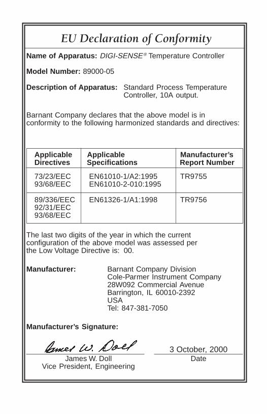
EU Declaration of ConformityName of Apparatus: DIGI-SENSE® Temperature Controller
Model Number: 89000-05
Description of Apparatus: Standard Process TemperatureController, 10A output.
Barnant Company declares that the above model is inconformity to the following harmonized standards and directives:
Applicable Applicable Manufacturer’sDirectives Specifications Report Number
73/23/EEC EN61010-1/A2:1995 TR975593/68/EEC EN61010-2-010:1995
89/336/EEC EN61326-1/A1:1998 TR975692/31/EEC93/68/EEC
The last two digits of the year in which the currentconfiguration of the above model was assessed perthe Low Voltage Directive is: 00.
Manufacturer: Barnant Company DivisionCole-Parmer Instrument Company28W092 Commercial AvenueBarrington, IL 60010-2392USATel: 847-381-7050
Manufacturer’s Signature:
James W. Doll DateVice President, Engineering
3 October, 2000
i
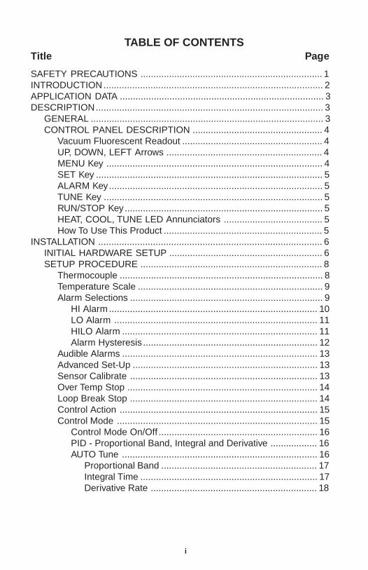
TABLE OF CONTENTSTitle Page
SAFETY PRECAUTIONS ...................................................................... 1INTRODUCTION.................................................................................... 2APPLICATION DATA .............................................................................. 3DESCRIPTION....................................................................................... 3
GENERAL ......................................................................................... 3CONTROL PANEL DESCRIPTION .................................................. 4
Vacuum Fluorescent Readout ...................................................... 4UP, DOWN, LEFT Arrows ............................................................ 4MENU Key ................................................................................... 4SET Key ....................................................................................... 5ALARM Key.................................................................................. 5TUNE Key .................................................................................... 5RUN/STOP Key............................................................................ 5HEAT, COOL, TUNE LED Annunciators ...................................... 5How To Use This Product ............................................................. 5
INSTALLATION ...................................................................................... 6INITIAL HARDWARE SETUP ........................................................... 6SETUP PROCEDURE ...................................................................... 8
Thermocouple .............................................................................. 8Temperature Scale ....................................................................... 9Alarm Selections .......................................................................... 9
HI Alarm ................................................................................ 10LO Alarm .............................................................................. 11HILO Alarm ........................................................................... 11Alarm Hysteresis ................................................................... 12
Audible Alarms ........................................................................... 13Advanced Set-Up ....................................................................... 13Sensor Calibrate ........................................................................ 13Over Temp Stop ......................................................................... 14Loop Break Stop ........................................................................ 14Control Action ............................................................................ 15Control Mode ............................................................................. 15
Control Mode On/Off ............................................................. 16PID - Proportional Band, Integral and Derivative .................. 16AUTO Tune ........................................................................... 16
Proportional Band ............................................................ 17Integral Time .................................................................... 17Derivative Rate ................................................................ 18
ii
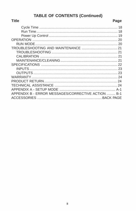
TABLE OF CONTENTS (Continued)Title Page
Cycle Time ................................................................................. 18Run Time.................................................................................... 18Power Up Control ....................................................................... 19
OPERATION ........................................................................................ 20RUN MODE..................................................................................... 20
TROUBLESHOOTING AND MAINTENANCE ..................................... 21TROUBLESHOOTING .................................................................... 21CALIBRATION ................................................................................ 21MAINTENANCE/CLEANING........................................................... 21
SPECIFICATIONS ............................................................................... 22INPUTS ........................................................................................... 23OUTPUTS ....................................................................................... 23
WARRANTY......................................................................................... 24PRODUCT RETURN............................................................................ 24TECHNICAL ASSISTANCE ................................................................. 24APPENDIX A - SETUP MODE .......................................................... A-1APPENDIX B - ERROR MESSAGES/CORRECTIVE ACTION ......... B-1ACCESSORIES ...................................................................BACK PAGE
1
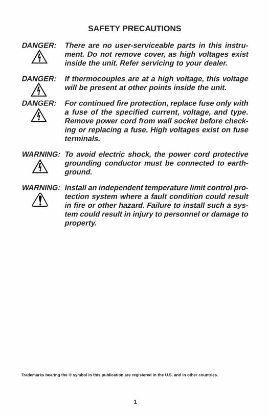
SAFETY PRECAUTIONS
DANGER: There are no user-serviceable parts in this instru-ment. Do not remove cover, as high voltages existinside the unit. Refer servicing to your dealer.
DANGER: If thermocouples are at a high voltage, this voltagewill be present at other points inside the unit.
DANGER: For continued fire protection, replace fuse only witha fuse of the specified current, voltage, and type.Remove power cord from wall socket before check-ing or replacing a fuse. High voltages exist on fuseterminals.
WARNING: To avoid electric shock, the power cord protectivegrounding conductor must be connected to earth-ground.
WARNING: Install an independent temperature limit control pro-tection system where a fault condition could resultin fire or other hazard. Failure to install such a sys-tem could result in injury to personnel or damage toproperty.
Trademarks bearing the ® symbol in this publication are registered in the U.S. and in other countries.

2
INTRODUCTION
This manual provides information for installing and operating the Tempera-ture Controller (standard model).
Refer to Figure 1 for a view of the front panel of the Temperature Controller.Refer to Figures 2 and 3 for a view of the back panels of the 115 or 230 Vversions.
FIGURE 1. TEMPERATURE CONTROLLER
FIGURE 2. TEMPERATURE CONTROLLER, BACK PANEL(115 V MODEL)
3
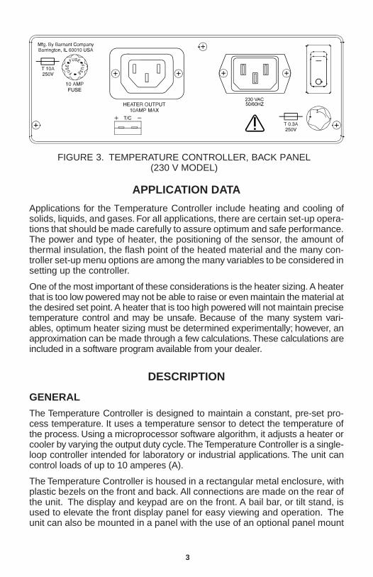
FIGURE 3. TEMPERATURE CONTROLLER, BACK PANEL(230 V MODEL)
APPLICATION DATA
Applications for the Temperature Controller include heating and cooling ofsolids, liquids, and gases. For all applications, there are certain set-up opera-tions that should be made carefully to assure optimum and safe performance.The power and type of heater, the positioning of the sensor, the amount ofthermal insulation, the flash point of the heated material and the many con-troller set-up menu options are among the many variables to be considered insetting up the controller.
One of the most important of these considerations is the heater sizing. A heaterthat is too low powered may not be able to raise or even maintain the material atthe desired set point. A heater that is too high powered will not maintain precisetemperature control and may be unsafe. Because of the many system vari-ables, optimum heater sizing must be determined experimentally; however, anapproximation can be made through a few calculations. These calculations areincluded in a software program available from your dealer.
DESCRIPTION
GENERAL
The Temperature Controller is designed to maintain a constant, pre-set pro-cess temperature. It uses a temperature sensor to detect the temperature ofthe process. Using a microprocessor software algorithm, it adjusts a heater orcooler by varying the output duty cycle. The Temperature Controller is a single-loop controller intended for laboratory or industrial applications. The unit cancontrol loads of up to 10 amperes (A).
The Temperature Controller is housed in a rectangular metal enclosure, withplastic bezels on the front and back. All connections are made on the rear ofthe unit. The display and keypad are on the front. A bail bar, or tilt stand, isused to elevate the front display panel for easy viewing and operation. Theunit can also be mounted in a panel with the use of an optional panel mount
4
kit. A two-line, 16-character, 14-segment vacuum fluorescent display is usedfor display of operating, setup, and alarm parameters.
A number of accessories can be used with this Temperature Controller, includ-ing various types of temperature sensors, heating units, cooling units (such asfans or pumps), remote alarms, and recorders.
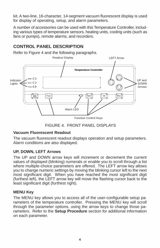
CONTROL PANEL DESCRIPTIONRefer to Figure 4 and the following paragraphs.
IndicatorLights
UP and DOWN Arrows
Function Control Keys
Alarm LED
FIGURE 4. FRONT PANEL DISPLAYS
Readout Display LEFT Arrow
Vacuum Fluorescent ReadoutThe vacuum fluorescent readout displays operation and setup parameters.Alarm conditions are also displayed.
UP, DOWN, LEFT ArrowsThe UP and DOWN arrow keys will increment or decrement the currentvalues of displayed (blinking) numerals or enable you to scroll through a listwhere multiple-choice parameters are offered. The LEFT arrow key allowsyou to change numeric settings by moving the blinking cursor left to the nextmost significant digit. When you have reached the most significant digit(furthest left), the LEFT arrow key will move the flashing cursor back to theleast significant digit (furthest right).
MENU KeyThe MENU key allows you to access all of the user-configurable setup pa-rameters of the temperature controller. Pressing the MENU key will scrollthrough the parameter options, using the arrow keys to change those pa-rameters. Refer to the Setup Procedure section for additional informationon each parameter.
5
SET KeyThe SET key allows you to change the control setpoint (SP), using the arrowkeys. Pressing the SET key again will exit the setpoint mode.
ALARM KeyThe ALARM key enables you to acknowledge temperature control alarm con-ditions and silence the audible alarm. Pressing the ALARM key will eraseany alarm messages on the display and stop the ALARM from flashing. If thealarm condition is still present, the ALARM LED will remain on until the PV(process variable) is out of the alarm condition.
Refer to Setup Procedures for additional information on setting the appro-priate alarms.
TUNE KeyThe TUNE key will start an AUTO tune cycle. Heat (or cooling) is automati-cally applied to determine PID values. AUTO tuning must be enabled in thesetup mode for this key to function. Refer to the AUTO Tuning section foradditional information on this setting.
NOTE: When the TUNE key is pressed, the output is turned full on threetimes for a period of time and overshoot of the setpoint will occur.Do not use the AUTO tune feature if this would have an adverseaffect on your process.
RUN/STOP KeyPressing this key when the Temperature Controller is stopped will start thecontrol process and activate the load, if required. Pressing this key when theTemperature Controller is running will cause it to stop.
HEAT, COOL, TUNE LED AnnunciatorsThese three indicators will light to indicate Temperature Controller functions.The green HEAT light will turn on when power is being applied to the heateroutput. The green COOL light will turn on when the Temperature Controller is inthe cooling mode and power is applied to the cooler output. The yellow TUNElight will turn on when the Temperature Controller is in the AUTO tuning mode.
How to Use this ProductHere is a summary of the steps required to setup and operate the Tempera-ture Controller.
1. Install the unit.Setup your process.Plug the Controller power cord to an AC outlet, turn unit on.Plug the heater (or cooler) into the Controller rear panel and install in
your process.Connect a thermocouple sensor to the rear panel and install in your
process.
6
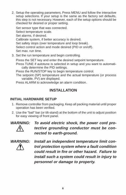
2. Setup the operating parameters. Press MENU and follow the interactivesetup selections. If your setup is the same as the factory set defaults,this step is not necessary. However, each of the setup options should bechecked for desired or proper setting.
Set sensor type that was connected.Select temperature scale.Set alarms, if desired.Calibrate system, if better accuracy is desired.Set safety stops (over temperature and loop break).Select control action and mode desired (PID or on/off).Set max. run time.
3. Set the run temperature and begin controlling.
Press the SET key and enter the desired setpoint temperature.Press TUNE if autotune is selected in setup and you want to automati-
cally determine the PID settings.Press the RUN/STOP key to begin temperature control.The setpoint (SP) temperature and the actual temperature (or process
variable, PV) are displayed.Press ALARM to acknowledge an alarm condition.
INSTALLATION
INITIAL HARDWARE SETUP1. Remove controller from packaging. Keep all packing material until proper
operation has been verified.
2. Use the "bail" bar (or tilt-stand) at the bottom of the unit to adjust positionfor easy viewing of front panel.
WARNING: To avoid electric shock, the power cord pro-tective grounding conductor must be con-nected to earth-ground.
WARNING: Install an independent temperature limit con-trol protection system where a fault conditioncould result in fire or other hazard. Failure toinstall such a system could result in injury topersonnel or damage to property.
7
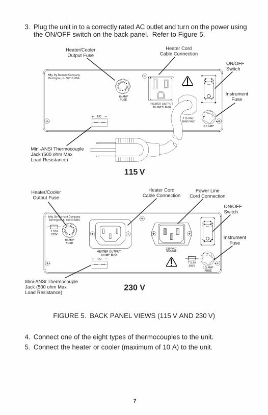
3. Plug the unit in to a correctly rated AC outlet and turn on the power usingthe ON/OFF switch on the back panel. Refer to Figure 5.
115 V
Heater/CoolerOutput Fuse
Heater CordCable Connection
ON/OFFSwitch
Mini-ANSI ThermocoupleJack (500 ohm MaxLoad Resistance)
Heater CordCable Connection
Heater/CoolerOutput Fuse
ON/OFFSwitch
InstrumentFuse
InstrumentFuse
Mini-ANSI ThermocoupleJack (500 ohm MaxLoad Resistance)
4. Connect one of the eight types of thermocouples to the unit.
5. Connect the heater or cooler (maximum of 10 A) to the unit.
230 V
FIGURE 5. BACK PANEL VIEWS (115 V AND 230 V)
Power LineCord Connection
8
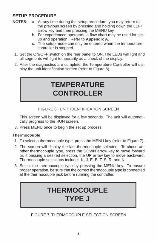
SETUP PROCEDURENOTES: a. At any time during the setup procedure, you may return to
the previous screen by pressing and holding down the LEFTarrow key and then pressing the MENU key.
b. For experienced operators, a flow chart may be used for set-up and operation. Refer to Appendix A .
c. The setup mode can only be entered when the temperaturecontroller is stopped.
1. Set the ON/OFF switch on the rear panel to ON. The LEDs will light andall segments will light temporarily as a check of the display.
2. After the diagnostics are complete, the Temperature Controller will dis-play the unit identification screen (refer to Figure 6).
TEMPERATURECONTROLLER
FIGURE 6. UNIT IDENTIFICATION SCREEN
This screen will be displayed for a few seconds. The unit will automati-cally progress to the RUN screen.
3. Press MENU once to begin the set up process.
Thermocouple1. To select a thermocouple type, press the MENU key (refer to Figure 7).
2. The screen will display the last thermocouple selected. To chose an-other thermocouple type, press the DOWN arrow key to move forwardor, if passing a desired selection, the UP arrow key to move backward.Thermocouple selections include: K, J, E, B, T, S, R, and N.
3. Select the thermocouple type by pressing the MENU key. To ensureproper operation, be sure that the correct thermocouple type is connectedat the thermocouple jack before running the controller.
THERMOCOUPLETYPE J
FIGURE 7. THERMOCOUPLE SELECTION SCREEN
9
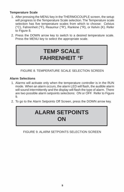
Temperature Scale1. After pressing the MENU key in the THERMOCOUPLE screen, the setup
will progress to the Temperature Scale selection. The Temperature scaleselection has five temperature scales from which to choose: Celsius(°C), Fahrenheit (°F), Reaumur (°R'), Rankine (°R), or Kelvin (K). Referto Figure 8.
2. Press the DOWN arrow key to switch to a desired temperature scale.Press the MENU key to select the appropriate scale.
TEMP SCALEFAHRENHEIT °F
FIGURE 8. TEMPERATURE SCALE SELECTION SCREEN
Alarm Selections1. Alarms will activate only when the temperature controller is in the RUN
mode. When an alarm occurs, the alarm LED will flash, the audible alarmwill sound intermittently and the display will flash the type of alarm. Thereare two possible alarm setpoints selections: ON or OFF. Refer to Figure9.
2. To go to the Alarm Setpoints Off Screen, press the DOWN arrow key.
ALARM SETPOINTSON
FIGURE 9. ALARM SETPOINTS SELECTION SCREEN
10
tivating the alarm.
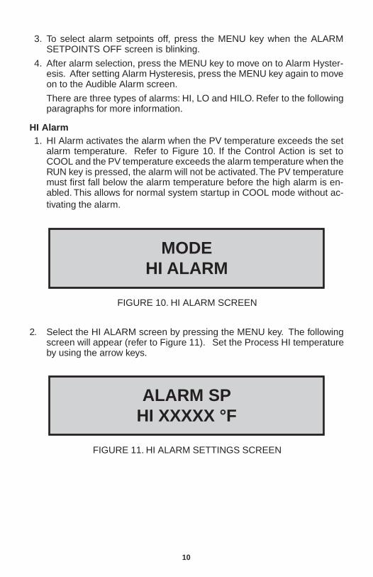
2. Select the HI ALARM screen by pressing the MENU key. The followingscreen will appear (refer to Figure 11). Set the Process HI temperatureby using the arrow keys.
MODEHI ALARM
FIGURE 10. HI ALARM SCREEN
ALARM SPHI XXXXX °F
FIGURE 11. HI ALARM SETTINGS SCREEN
3. To select alarm setpoints off, press the MENU key when the ALARMSETPOINTS OFF screen is blinking.
4. After alarm selection, press the MENU key to move on to Alarm Hyster-esis. After setting Alarm Hysteresis, press the MENU key again to moveon to the Audible Alarm screen.
There are three types of alarms: HI, LO and HILO. Refer to the followingparagraphs for more information.
HI Alarm1. HI Alarm activates the alarm when the PV temperature exceeds the set
alarm temperature. Refer to Figure 10. If the Control Action is set toCOOL and the PV temperature exceeds the alarm temperature when theRUN key is pressed, the alarm will not be activated. The PV temperaturemust first fall below the alarm temperature before the high alarm is en-abled. This allows for normal system startup in COOL mode without ac-
11
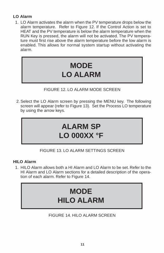
LO Alarm1. LO Alarm activates the alarm when the PV temperature drops below the
alarm temperature. Refer to Figure 12. If the Control Action is set toHEAT and the PV temperature is below the alarm temperature when theRUN Key is pressed, the alarm will not be activated. The PV tempera-ture must first rise above the alarm temperature before the low alarm isenabled. This allows for normal system startup without activating thealarm.
FIGURE 13. LO ALARM SETTINGS SCREEN
HILO Alarm1. HILO Alarm allows both a HI Alarm and LO Alarm to be set. Refer to the
HI Alarm and LO Alarm sections for a detailed description of the opera-tion of each alarm. Refer to Figure 14.
ALARM SPLO 000XX °F
FIGURE 14. HILO ALARM SCREEN
MODEHILO ALARM
MODELO ALARM
FIGURE 12. LO ALARM MODE SCREEN
2. Select the LO Alarm screen by pressing the MENU key. The followingscreen will appear (refer to Figure 13). Set the Process LO temperatureby using the arrow keys.
12
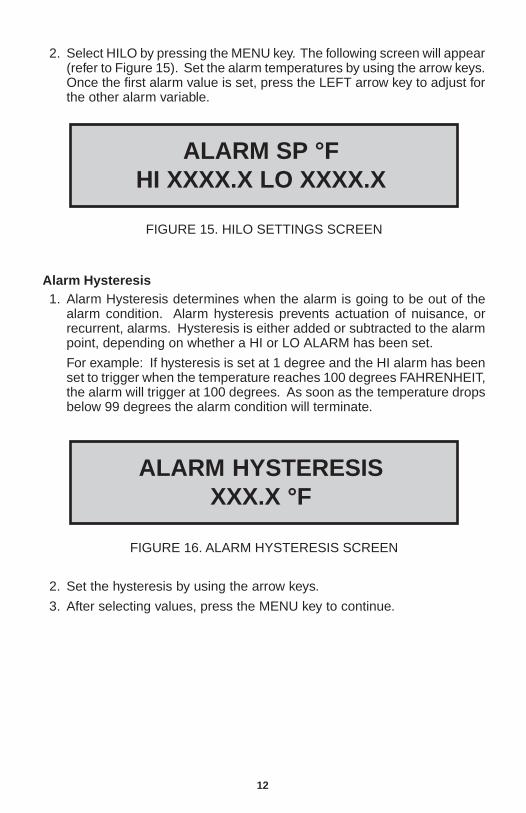
2. Select HILO by pressing the MENU key. The following screen will appear(refer to Figure 15). Set the alarm temperatures by using the arrow keys.Once the first alarm value is set, press the LEFT arrow key to adjust forthe other alarm variable.
FIGURE 15. HILO SETTINGS SCREEN
ALARM SP °FHI XXXX.X LO XXXX.X
2. Set the hysteresis by using the arrow keys.
3. After selecting values, press the MENU key to continue.
FIGURE 16. ALARM HYSTERESIS SCREEN
ALARM HYSTERESISXXX.X °F
Alarm Hysteresis1. Alarm Hysteresis determines when the alarm is going to be out of the
alarm condition. Alarm hysteresis prevents actuation of nuisance, orrecurrent, alarms. Hysteresis is either added or subtracted to the alarmpoint, depending on whether a HI or LO ALARM has been set.
For example: If hysteresis is set at 1 degree and the HI alarm has beenset to trigger when the temperature reaches 100 degrees FAHRENHEIT,the alarm will trigger at 100 degrees. As soon as the temperature dropsbelow 99 degrees the alarm condition will terminate.
13
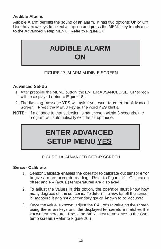
Audible AlarmsAudible Alarm permits the sound of an alarm. It has two options: On or Off.Use the arrow keys to select an option and press the MENU key to advanceto the Advanced Setup MENU. Refer to Figure 17.
FIGURE 17. ALARM AUDIBLE SCREEN
AUDIBLE ALARMON
Advanced Set-Up1. After pressing the MENU button, the ENTER ADVANCED SETUP screen
will be displayed (refer to Figure 18).
2. The flashing message YES will ask if you want to enter the AdvancedScreen. Press the MENU key as the word YES blinks.
NOTE: If a change to that selection is not chosen within 3 seconds, theprogram will automatically exit the setup mode.
ENTER ADVANCEDSETUP MENU YES
FIGURE 18. ADVANCED SETUP SCREEN
Sensor Calibrate1. Sensor Calibrate enables the operator to calibrate out sensor error
to give a more accurate reading. Refer to Figure 19. Calibrationoffset and PV (actual) temperatures are displayed.
2. To adjust the values in this option, the operator must know howmany degrees off the sensor is. To determine how far off the sensoris, measure it against a secondary gauge known to be accurate.
3. Once the value is known, adjust the CAL offset value on the screenusing the arrow keys until the displayed temperature matches theknown temperature. Press the MENU key to advance to the Overtemp screen. (Refer to Figure 20.)
14
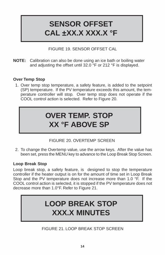
SENSOR OFFSETCAL ±±±±±XX.X XXX.X °F
FIGURE 19. SENSOR OFFSET CAL
NOTE: Calibration can also be done using an ice bath or boiling waterand adjusting the offset until 32.0 °F or 212 °F is displayed.
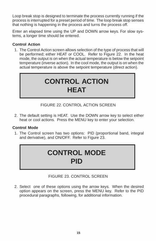
Over Temp Stop1. Over temp stop temperature, a safety feature, is added to the setpoint
(SP) temperature. If the PV temperature exceeds this amount, the tem-perature controller will stop. Over temp stop does not operate if theCOOL control action is selected. Refer to Figure 20.
OVER TEMP. STOPXX °F ABOVE SP
FIGURE 20. OVERTEMP SCREEN
2. To change the Overtemp value, use the arrow keys. After the value hasbeen set, press the MENU key to advance to the Loop Break Stop Screen.
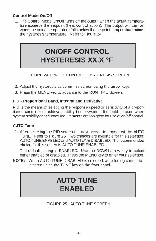
Loop Break StopLoop break stop, a safety feature, is designed to stop the temperaturecontroller if the heater output is on for the amount of time set in Loop BreakStop and the PV temperature does not increase more than 1.0 °F. If theCOOL control action is selected, it is stopped if the PV temperature does notdecrease more than 1.0°F. Refer to Figure 21.
LOOP BREAK STOPXXX.X MINUTES
FIGURE 21. LOOP BREAK STOP SCREEN
15
Loop break stop is designed to terminate the process currently running if theprocess is interrupted for a preset period of time. The loop break stop sensesthat nothing is happening in the process and turns the process off.
Enter an elapsed time using the UP and DOWN arrow keys. For slow sys-tems, a longer time should be entered.
Control Action1. The Control Action screen allows selection of the type of process that will
be performed; either HEAT or COOL. Refer to Figure 22. In the heatmode, the output is on when the actual temperature is below the setpointtemperature (inverse action). In the cool mode, the output is on when theactual temperature is above the setpoint temperature (direct action).
CONTROL ACTIONHEAT
FIGURE 22. CONTROL ACTION SCREEN
2. The default setting is HEAT. Use the DOWN arrow key to select eitherheat or cool actions. Press the MENU key to enter your selection.
Control Mode1. The Control screen has two options: PID (proportional band, integral
and derivative), and ON/OFF. Refer to Figure 23.
CONTROL MODEPID
FIGURE 23. CONTROL SCREEN
2. Select one of these options using the arrow keys. When the desiredoption appears on the screen, press the MENU key. Refer to the PIDprocedural paragraphs, following, for additional information.
16
Control Mode On/Off1. The Control Mode On/Off turns off the output when the actual tempera-
ture exceeds the setpoint (heat control action). The output will turn onwhen the actual temperature falls below the setpoint temperature minusthe hysteresis temperature. Refer to Figure 24.
ON/OFF CONTROLHYSTERESIS XX.X °F
FIGURE 24. ON/OFF CONTROL HYSTERESIS SCREEN
2. Adjust the hysteresis value on this screen using the arrow keys.
3. Press the MENU key to advance to the RUN TIME Screen.
PID - Proportional Band, Integral and Derivative
PID is the means of selecting the response speed or sensitivity of a propor-tioned controller to achieve stability in the system. It should be used whensystem stability or accuracy requirements are too great for use of on/off control.
AUTO Tune
1. After selecting the PID screen the next screen to appear will be AUTOTUNE. Refer to Figure 25. Two choices are available for this selection:AUTO TUNE ENABLED and AUTO TUNE DISABLED. The recommendedchoice for this screen is AUTO TUNE ENABLED.
The default setting is ENABLED. Use the DOWN arrow key to selecteither enabled or disabled. Press the MENU key to enter your selection.
NOTE: When AUTO TUNE DISABLED is selected, auto tuning cannot beinitiated using the TUNE key on the front panel.
AUTO TUNEENABLED
FIGURE 25. AUTO TUNE SCREEN
17
2. Select an option using the arrow keys.
3. If AUTO TUNE ENABLED is selected, press the MENU key four times toadvance past the PID setup to the Cycle Time screen.
NOTE: AUTO TUNE DISABLED is also a safety feature to preventaccidental auto tuning.
Propor tional Band1. Select the proportional band by pressing the MENU key. The following
screen will appear (refer to Figure 26).
2. Use the arrow keys to enter the correct value and press the MENU key.
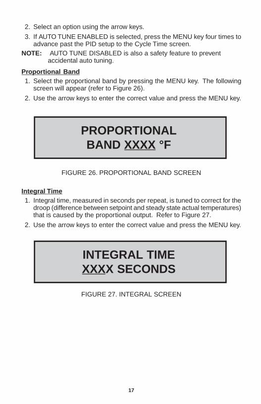
PROPORTIONALBAND XXXX °F
Integral Time1. Integral time, measured in seconds per repeat, is tuned to correct for the
droop (difference between setpoint and steady state actual temperatures)that is caused by the proportional output. Refer to Figure 27.
2. Use the arrow keys to enter the correct value and press the MENU key.
INTEGRAL TIMEXXXX SECONDS
FIGURE 27. INTEGRAL SCREEN
FIGURE 26. PROPORTIONAL BAND SCREEN
18
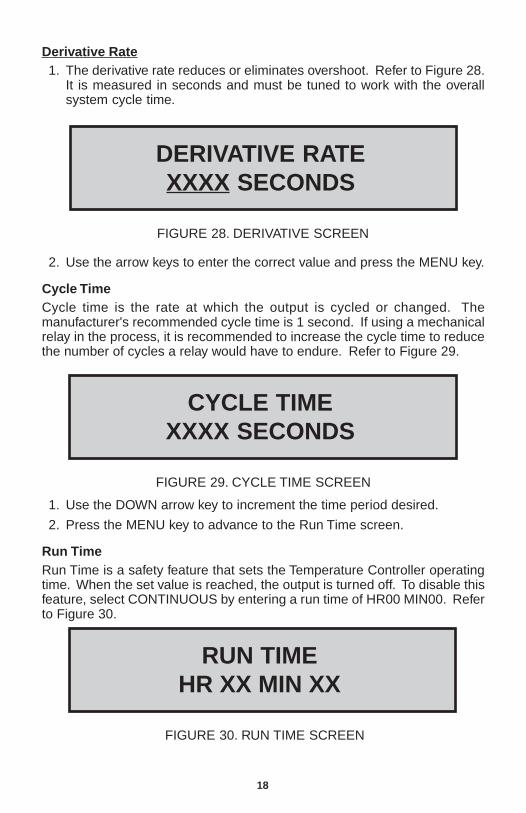
Deriv ative Rate1. The derivative rate reduces or eliminates overshoot. Refer to Figure 28.
It is measured in seconds and must be tuned to work with the overallsystem cycle time.
DERIVATIVE RATEXXXX SECONDS
FIGURE 28. DERIVATIVE SCREEN
2. Use the arrow keys to enter the correct value and press the MENU key.
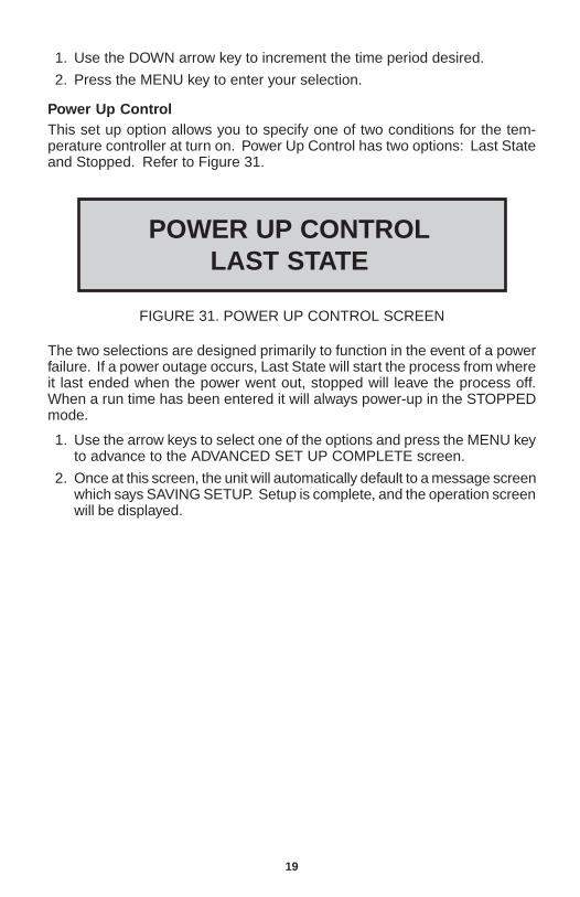
Cycle TimeCycle time is the rate at which the output is cycled or changed. Themanufacturer's recommended cycle time is 1 second. If using a mechanicalrelay in the process, it is recommended to increase the cycle time to reducethe number of cycles a relay would have to endure. Refer to Figure 29.
CYCLE TIMEXXXX SECONDS
FIGURE 29. CYCLE TIME SCREEN
1. Use the DOWN arrow key to increment the time period desired.
2. Press the MENU key to advance to the Run Time screen.
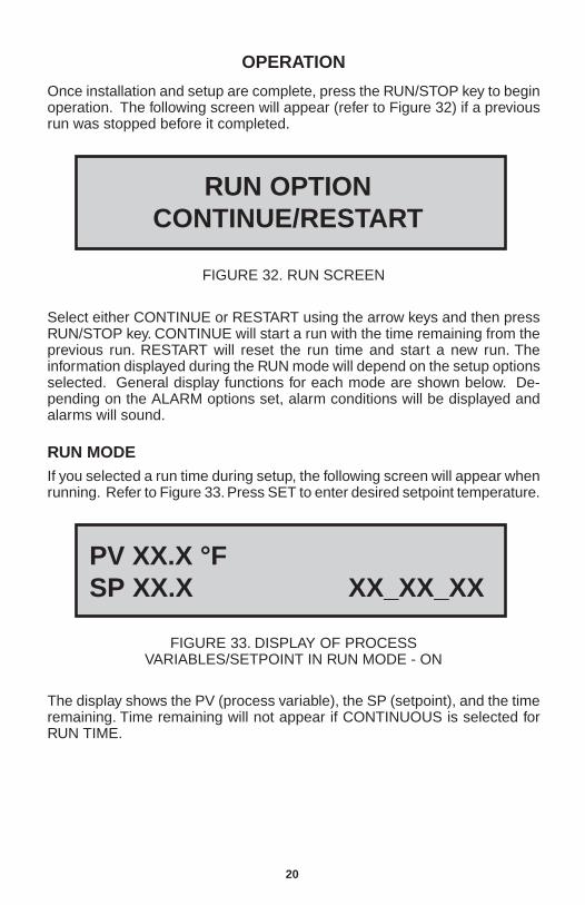
Run TimeRun Time is a safety feature that sets the Temperature Controller operatingtime. When the set value is reached, the output is turned off. To disable thisfeature, select CONTINUOUS by entering a run time of HR00 MIN00. Referto Figure 30.
RUN TIMEHR XX MIN XX
FIGURE 30. RUN TIME SCREEN
19
1. Use the DOWN arrow key to increment the time period desired.
2. Press the MENU key to enter your selection.
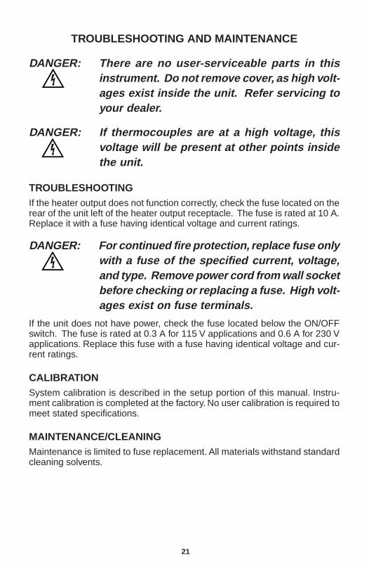
Power Up ControlThis set up option allows you to specify one of two conditions for the tem-perature controller at turn on. Power Up Control has two options: Last Stateand Stopped. Refer to Figure 31.
POWER UP CONTROLLAST STATE
FIGURE 31. POWER UP CONTROL SCREEN
The two selections are designed primarily to function in the event of a powerfailure. If a power outage occurs, Last State will start the process from whereit last ended when the power went out, stopped will leave the process off.When a run time has been entered it will always power-up in the STOPPEDmode.
1. Use the arrow keys to select one of the options and press the MENU keyto advance to the ADVANCED SET UP COMPLETE screen.
2. Once at this screen, the unit will automatically default to a message screenwhich says SAVING SETUP. Setup is complete, and the operation screenwill be displayed.
20
OPERATION
Once installation and setup are complete, press the RUN/STOP key to beginoperation. The following screen will appear (refer to Figure 32) if a previousrun was stopped before it completed.
RUN OPTIONCONTINUE/RESTART
FIGURE 32. RUN SCREEN
Select either CONTINUE or RESTART using the arrow keys and then pressRUN/STOP key. CONTINUE will start a run with the time remaining from theprevious run. RESTART will reset the run time and start a new run. Theinformation displayed during the RUN mode will depend on the setup optionsselected. General display functions for each mode are shown below. De-pending on the ALARM options set, alarm conditions will be displayed andalarms will sound.
RUN MODEIf you selected a run time during setup, the following screen will appear whenrunning. Refer to Figure 33. Press SET to enter desired setpoint temperature.
PV XX.X °FSP XX.X XX_XX_XX
FIGURE 33. DISPLAY OF PROCESSVARIABLES/SETPOINT IN RUN MODE - ON
The display shows the PV (process variable), the SP (setpoint), and the timeremaining. Time remaining will not appear if CONTINUOUS is selected forRUN TIME.
21
TROUBLESHOOTING AND MAINTENANCE
DANGER: There are no user-serviceable parts in thisinstrument. Do not remove cover, as high volt-ages exist inside the unit. Refer servicing toyour dealer.
DANGER: If thermocouples are at a high voltage, thisvoltage will be present at other points insidethe unit.
TROUBLESHOOTINGIf the heater output does not function correctly, check the fuse located on therear of the unit left of the heater output receptacle. The fuse is rated at 10 A.Replace it with a fuse having identical voltage and current ratings.
DANGER: For continued fire protection, replace fuse onlywith a fuse of the specified current, voltage,and type. Remove power cord from wall socketbefore checking or replacing a fuse. High volt-ages exist on fuse terminals.
If the unit does not have power, check the fuse located below the ON/OFFswitch. The fuse is rated at 0.3 A for 115 V applications and 0.6 A for 230 Vapplications. Replace this fuse with a fuse having identical voltage and cur-rent ratings.
CALIBRATIONSystem calibration is described in the setup portion of this manual. Instru-ment calibration is completed at the factory. No user calibration is required tomeet stated specifications.
MAINTENANCE/CLEANINGMaintenance is limited to fuse replacement. All materials withstand standardcleaning solvents.
22
SPECIFICATIONS
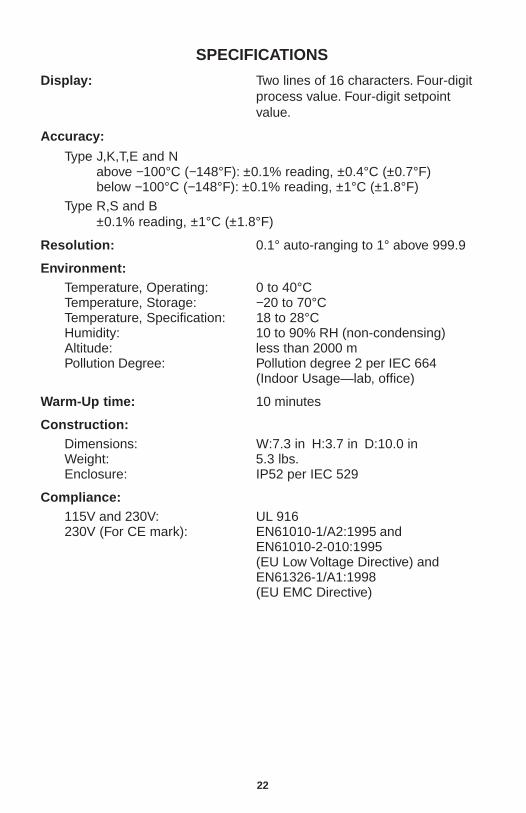
Display: Two lines of 16 characters. Four-digitprocess value. Four-digit setpointvalue.
Accuracy:
Type J,K,T,E and Nabove −100°C (−148°F): ±0.1% reading, ±0.4°C (±0.7°F)below −100°C (−148°F): ±0.1% reading, ±1°C (±1.8°F)
Type R,S and B±0.1% reading, ±1°C (±1.8°F)
Resolution: 0.1° auto-ranging to 1° above 999.9
Environment:Temperature, Operating: 0 to 40°CTemperature, Storage: −20 to 70°CTemperature, Specification: 18 to 28°CHumidity: 10 to 90% RH (non-condensing)Altitude: less than 2000 mPollution Degree: Pollution degree 2 per IEC 664
(Indoor Usage—lab, office)
Warm-Up time: 10 minutes
Construction:Dimensions: W:7.3 in H:3.7 in D:10.0 inWeight: 5.3 lbs.Enclosure: IP52 per IEC 529
Compliance:115V and 230V: UL 916230V (For CE mark): EN61010-1/A2:1995 and
EN61010-2-010:1995(EU Low Voltage Directive) andEN61326-1/A1:1998(EU EMC Directive)
23
SPECIFICATIONS (Continued)
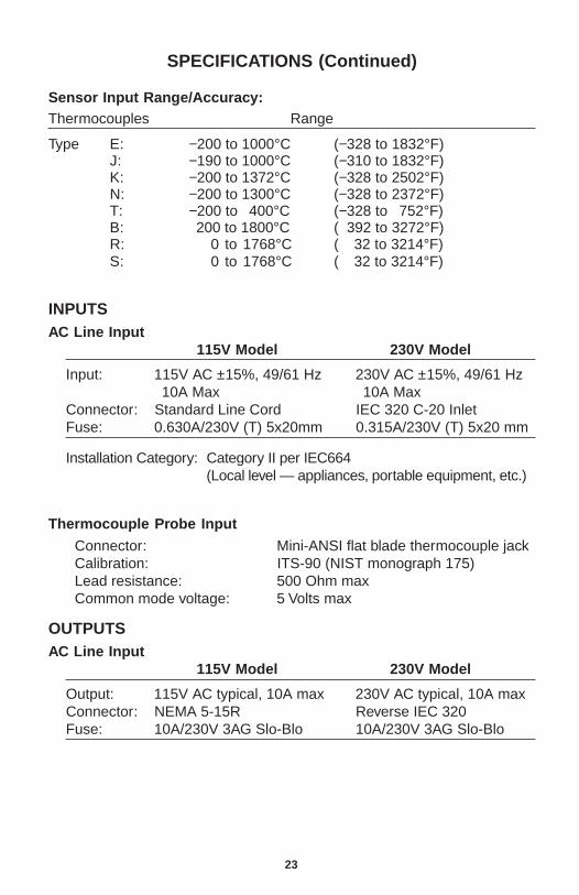
Sensor Input Range/Accuracy:Thermocouples Range
Type E: −200 to 1000°C (−328 to 1832°F)J: −190 to 1000°C (−310 to 1832°F)K: −200 to 1372°C (−328 to 2502°F)N: −200 to 1300°C (−328 to 2372°F)T: −200 to 400°C (−328 to 752°F)B: 200 to 1800°C (−392 to 3272°F)R: 0 to 1768°C (− 32 to 3214°F)S: 0 to 1768°C (− 32 to 3214°F)
INPUTSAC Line Input
115V Model 230V Model
Input: 115V AC ±15%, 49/61 Hz 230V AC ±15%, 49/61 Hz10A Max 10A Max
Connector: Standard Line Cord IEC 320 C-20 InletFuse: 0.630A/230V (T) 5x20mm 0.315A/230V (T) 5x20 mm
Installation Category: Category II per IEC664(Local level — appliances, portable equipment, etc.)
Thermocouple Probe Input
Connector: Mini-ANSI flat blade thermocouple jackCalibration: ITS-90 (NIST monograph 175)Lead resistance: 500 Ohm maxCommon mode voltage: 5 Volts max
OUTPUTSAC Line Input
115V Model 230V Model
Output: 115V AC typical, 10A max 230V AC typical, 10A maxConnector: NEMA 5-15R Reverse IEC 320Fuse: 10A/230V 3AG Slo-Blo 10A/230V 3AG Slo-Blo
24
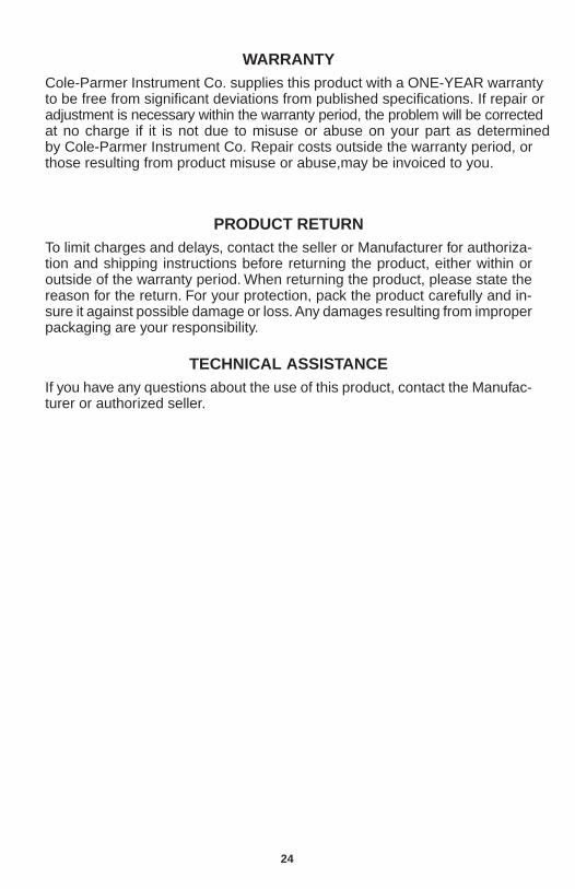
WARRANTYCole-Parmer Instrument Co. supplies this product with a ONE-YEAR warranty to be free from significant deviations from published specifications. If repair or adjustment is necessary within the warranty period, the problem will be corrected at no charge if it is not due to misuse or abuse on your part as determined by Cole-Parmer Instrument Co. Repair costs outside the warranty period, or those resulting from product misuse or abuse,may be invoiced to you.
PRODUCT RETURNTo limit charges and delays, contact the seller or Manufacturer for authoriza-tion and shipping instructions before returning the product, either within oroutside of the warranty period. When returning the product, please state thereason for the return. For your protection, pack the product carefully and in-sure it against possible damage or loss. Any damages resulting from improperpackaging are your responsibility.
TECHNICAL ASSISTANCEIf you have any questions about the use of this product, contact the Manufac-turer or authorized seller.
25A-1
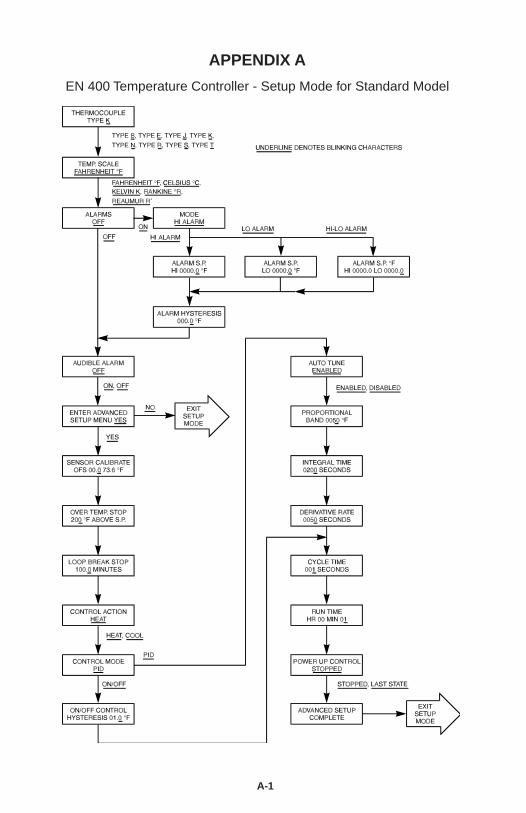
APPENDIX A
EN 400 Temperature Controller - Setup Mode for Standard Model
APPENDIX B
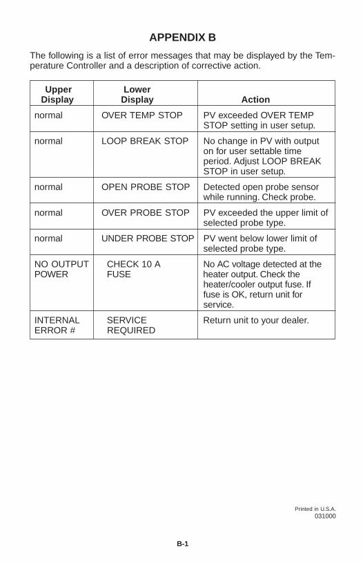
The following is a list of error messages that may be displayed by the Tem-perature Controller and a description of corrective action.
Upper LowerDisplay Display Action
normal OVER TEMP STOP PV exceeded OVER TEMPSTOP setting in user setup.
normal LOOP BREAK STOP No change in PV with outputon for user settable timeperiod. Adjust LOOP BREAKSTOP in user setup.
normal OPEN PROBE STOP Detected open probe sensorwhile running. Check probe.
normal OVER PROBE STOP PV exceeded the upper limit ofselected probe type.
normal UNDER PROBE STOP PV went below lower limit ofselected probe type.
NO OUTPUT CHECK 10 A No AC voltage detected at thePOWER FUSE heater output. Check the
heater/cooler output fuse. Iffuse is OK, return unit forservice.
INTERNAL SERVICE Return unit to your dealer.ERROR # REQUIRED
Printed in U.S.A.031000
B-1
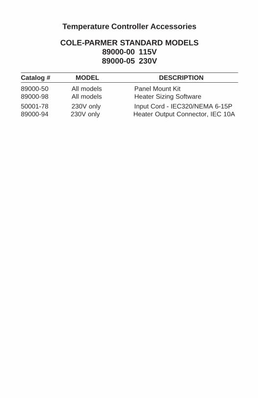
Temperature Controller Accessories
COLE-PARMER STANDARD MODELS89000-00 115V89000-05 230V
Catalog # MODEL DESCRIPTION
89000-50 All models Panel Mount Kit89000-98 All models Heater Sizing Software
50001-78 230V only Input Cord - IEC320/NEMA 6-15P89000-94 230V only Heater Output Connector, IEC 10A