Embed Size (px)
Citation preview
Modular Temperature Controller E5ZN I-129
Tem
per
atu
reC
on
tro
ller
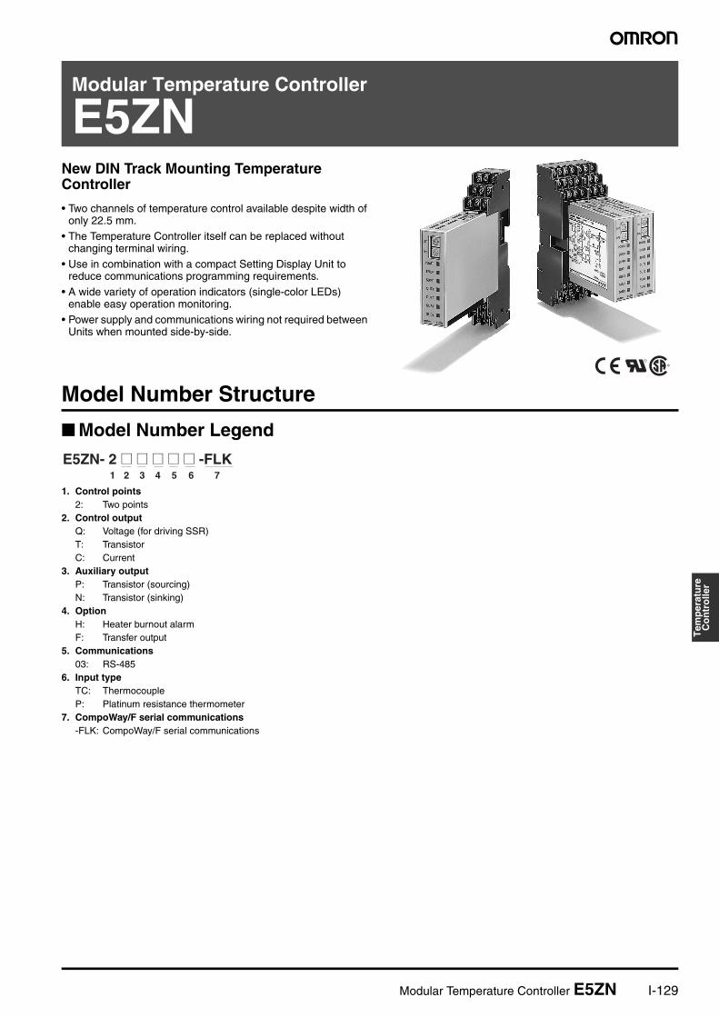
Modular Temperature Controller
E5ZNNew DIN Track Mounting Temperature Controller
• Two channels of temperature control available despite width of only 22.5 mm.
• The Temperature Controller itself can be replaced without changing terminal wiring.
• Use in combination with a compact Setting Display Unit to reduce communications programming requirements.
• A wide variety of operation indicators (single-color LEDs) enable easy operation monitoring.
• Power supply and communications wiring not required between Units when mounted side-by-side.
®
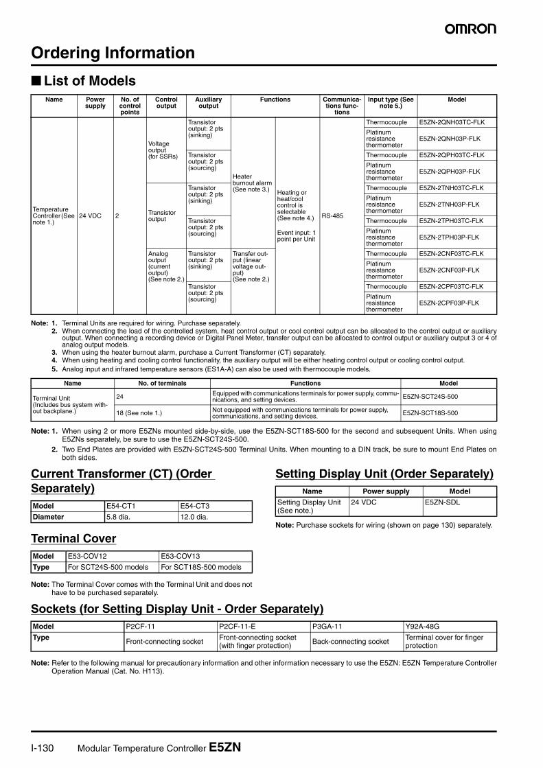
Model Number Structure
Model Number Legend
1. Control points2: Two points
2. Control outputQ: Voltage (for driving SSR)T: TransistorC: Current
3. Auxiliary outputP: Transistor (sourcing)N: Transistor (sinking)
4. OptionH: Heater burnout alarmF: Transfer output
5. Communications03: RS-485
6. Input typeTC: ThermocoupleP: Platinum resistance thermometer
7. CompoWay/F serial communications-FLK: CompoWay/F serial communications
1 2 3 4 5 6 7
E5ZN- 2 @ @ @ @ @ -FLK
I-130 Modular Temperature Controller E5ZN
Ordering Information
List of Models
Note: 1. Terminal Units are required for wiring. Purchase separately.2. When connecting the load of the controlled system, heat control output or cool control output can be allocated to the control output or auxiliary
output. When connecting a recording device or Digital Panel Meter, transfer output can be allocated to control output or auxiliary output 3 or 4 ofanalog output models.
3. When using the heater burnout alarm, purchase a Current Transformer (CT) separately.4. When using heating and cooling control functionality, the auxiliary output will be either heating control output or cooling control output.5. Analog input and infrared temperature sensors (ES1A-A) can also be used with thermocouple models.
Note: 1. When using 2 or more E5ZNs mounted side-by-side, use the E5ZN-SCT18S-500 for the second and subsequent Units. When usingE5ZNs separately, be sure to use the E5ZN-SCT24S-500.
2. Two End Plates are provided with E5ZN-SCT24S-500 Terminal Units. When mounting to a DIN track, be sure to mount End Plates onboth sides.
Current Transformer (CT) (Order Separately)
Terminal Cover
Note: The Terminal Cover comes with the Terminal Unit and does nothave to be purchased separately.
Setting Display Unit (Order Separately)
Note: Purchase sockets for wiring (shown on page 130) separately.
Sockets (for Setting Display Unit - Order Separately)
Note: Refer to the following manual for precautionary information and other information necessary to use the E5ZN: E5ZN Temperature ControllerOperation Manual (Cat. No. H113).
Name Power supply
No. of control points
Control output
Auxiliary output
Functions Communica-tions func-
tions
Input type (See note 5.)
Model
Temperature Controller (See note 1.)
24 VDC 2
Voltage output(for SSRs)
Transistor output: 2 pts (sinking)
Heater burnout alarm (See note 3.) Heating or
heat/cool control is selectable (See note 4.)
Event input: 1 point per Unit
RS-485
Thermocouple E5ZN-2QNH03TC-FLK
Platinum resistance thermometer
E5ZN-2QNH03P-FLK
Transistor output: 2 pts (sourcing)
Thermocouple E5ZN-2QPH03TC-FLK
Platinum resistance thermometer
E5ZN-2QPH03P-FLK
Transistor output
Transistor output: 2 pts (sinking)
Thermocouple E5ZN-2TNH03TC-FLK
Platinum resistance thermometer
E5ZN-2TNH03P-FLK
Transistor output: 2 pts (sourcing)
Thermocouple E5ZN-2TPH03TC-FLK
Platinum resistance thermometer
E5ZN-2TPH03P-FLK
Analog output (current output)(See note 2.)
Transistor output: 2 pts (sinking)
Transfer out-put (linear voltage out-put)(See note 2.)
Thermocouple E5ZN-2CNF03TC-FLK
Platinum resistance thermometer
E5ZN-2CNF03P-FLK
Transistor output: 2 pts (sourcing)
Thermocouple E5ZN-2CPF03TC-FLK
Platinum resistance thermometer
E5ZN-2CPF03P-FLK
Name No. of terminals Functions Model
Terminal Unit(Includes bus system with-out backplane.)
24 Equipped with communications terminals for power supply, commu-nications, and setting devices. E5ZN-SCT24S-500
18 (See note 1.) Not equipped with communications terminals for power supply, communications, and setting devices. E5ZN-SCT18S-500
Model E54-CT1 E54-CT3
Diameter 5.8 dia. 12.0 dia.
Model E53-COV12 E53-COV13
Type For SCT24S-500 models For SCT18S-500 models
Name Power supply Model
Setting Display Unit (See note.)
24 VDC E5ZN-SDL
Model P2CF-11 P2CF-11-E P3GA-11 Y92A-48G
Type Front-connecting socket Front-connecting socket (with finger protection) Back-connecting socket Terminal cover for finger
protection
Modular Temperature Controller E5ZN I-131
Tem
per
atu
reC
on
tro
ller
Specifications
Ratings
Note: 1. ES1A models with a temperature range of 160×C to 260×C have been discontinued.2. OMRON G32A-EA Cycle Controller Unit (load impedance 352 Ω) can be used.
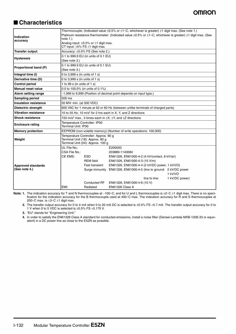
Input RangePlatinum Resistance Thermometer Models and Thermocouple Models
The applicable standards for the input types are as follows:• K, J, T, E, N, R, S, B: JIS C1602-1995, IEC584-1• L: Fe-CuNi, DIN 43710-1985• U: Cu-CuNi, DIN 43710-1985• JPt100: JIS C 1604-1989, JIS C 1606-1989• Pt100: JIS C 1604-1997 IEC 751Shaded parts indicate the settings at the time of purchase.Note: ES1A models with a temperature range of 160×C to 260×C have been discontinued.
Power supply voltage 24 VDC
Allowable voltage range 85% to 110% of the rated power supply voltage
Power consumption Approx. 3 W
Sensor input
Thermocouple: K, J, T, E, L, U, N, R, S, BInfrared temperature sensor (ES1A series): 10 to 70×C, 60 to 120×C, 115 to 165×C, 160 to 260×C (See note 1.)Voltage input: 0 to 50 mV
Platinum resistance thermometer: Pt100, JPt100
Control output
Voltage output(for driving SSR)
Output voltage: 12 VDC ±15% (PNP);Maximum load current: 21 mA;Equipped with short-circuit protection circuit
Transistor output
Maximum operational voltage: 30 VDC;Maximum load current: 100 mA;Residual voltage: 1.5 V max.;Leakage current: 0.4 mA max.
Current output Current output range: 4 to 20/0 to 20 mA DC;Load: 350 Ω max. (See note 2.)
Auxiliary outputTransistor output
Sourcing Maximum operating voltage: 30 VDC;Maximum load current: 50 mA;Residual voltage: 1.5 V max.;Leakage current: 0.4 mA max.Sinking
Linear voltage output Voltage output range: 1 to 5/0 to 5 VDC;Load: 10 kΩ min.
Event input
Contact output ON: 1 kΩ max., OFF: 100 kΩ min.Discharge current: Approx. 7 mA
Non-contact output ON: Residual voltage: 1.5 V max., OFF: Leakage current: 0.1 mA max.Discharge current: Approx. 7 mA
Number of input and control points Input points: 2, Control points: 2
Setting method Via communications or using the Setting Display Unit (E5ZN-SDL)
Control method 2-PID or ON/OFF control
Other functions Heater burnout detection function, transfer output functionMulti-SP and RUN/STOP switching using event input
Ambient operatingtemperature
−10 to 55×C (with no icing or condensation)For 3 years of assured use: −10 to 50×C
Ambient operating humidity 25% to 85%
Storage temperature −25 to 65×C (with no icing or condensation)
180017001600150014001300120011001000
900800700600500400300200100
0−100−200
0 1 2 3 4 0 1 2 3 4 17 5 6 7 18 8 9 10 11 12 13 14 15 16−200 −200−199.9 −199.9
500.0 500.0
0.0 0.0
100.0 100.0
−20.0 −100 −20.0−200 −199.9 −199.9
0−100
−200 −200
0 0100.0
0 0 0 0
260165120
90
400400
850
600
400.0400.0400.0500.0
850850
1300 1300
1700 17001800
Platinum resistance thermometer modelsPlatinum resistance
thermometerInput type
Name
Te
mp
era
ture
ra
ng
e (
°C)
Setting number
K J T E L U N R S BPt100 JPt100
Thermocouple
Thermocouple models
Infrared temperature sensor (ES1A) Analog input
0 to 50 mV
−1999 to 9999 or −199.9 to 999.9 by scaling
10 to 70°C
60 to 120°C
115 to165°C
160 to260°C
I-132 Modular Temperature Controller E5ZN
Characteristics
Note: 1. The indication accuracy for T and N thermocouples at −100×C, and for U and L thermocouples is ±2×C ±1 digit max. There is no speci-fication for the indication accuracy for the B thermocouple used at 400×C max. The indication accuracy for R and S thermocouples at200×C max. is ±3×C ±1 digit max.
2. The transfer output accuracy for 0 to 4 mA when 0 to 20 mA DC is selected is ±0.5% FS +0.7 mA. The transfer output accuracy for 0 to1 V when 0 to 5 VDC is selected is ±0.5% FS +0.175 V.
3. “EU” stands for “Engineering Unit.”4. In order to satisfy the EN61326 Class A standard for conducted emissions, install a noise filter (Densei-Lambda MXB-1206-33 or equiv-
alent) in a DC power line as close to the E5ZN as possible.
Indicationaccuracy
Thermocouple: (Indicated value ±0.5% or ±1×C, whichever is greater) ±1 digit max. (See note 1.)Platinum resistance thermometer: (Indicated value ±0.5% or ±1×C, whichever is greater) ±1 digit max. (See note 1.)Analog input: ±0.5% or ±1 digit max.CT input: ±5% FS ±1 digit max.
Transfer output Accuracy: ±0.5% FS (See note 2.)
Hysteresis0.1 to 999.9 EU (in units of 0.1 EU)(See note 3.)
Proportional band (P)0.1 to 999.9 EU (in units of 0.1 EU)(See note 3.)
Integral time (I) 0 to 3,999 s (in units of 1 s)
Derivative time (D) 0 to 3,999 s (in units of 1 s)
Control period 1 to 99 s (in units of 1 s)
Manual reset value 0.0 to 100.0% (in units of 0.1%)
Alarm setting range −1,999 to 9,999 (Position of decimal point depends on input type.)
Sampling period 500 ms
Insulation resistance 20 MW min. (at 500 VDC)
Dielectric strength 600 VAC for 1 minute at 50 or 60 Hz (between unlike terminals of charged parts)
Vibration resistance 10 to 55 Hz, 10 m/s2 for 2 hrs each in X, Y, and Z directions
Shock resistance 150 m/s2 max., 3 times each in ±X, ±Y, and ±Z directions
Enclosure rating Temperature Controller: IP00Terminal Unit: IP00
Memory protection EEPROM (non-volatile memory) (Number of write operations: 100,000)
WeightTemperature Controller: Approx. 90 gTerminal Unit (18): Approx. 80 gTerminal Unit (24): Approx. 100 g
Approved standards(See note 4.)
UL File No.: E200593CSA File No.: 203889-1140084CE EMS: ESD EN61326, EN61000-4-2 (4 kV/contact, 8 kV/air)
REM field EN61326, EN61000-4-3 (10 V/m)Fast transient EN61326, EN61000-4-4 (2 kV/DC power, 1 kV/I/O)Surge immunity EN61326, EN61000-4-5 (line to ground: 2 kV/DC power
1 kV/I/Oline to line: 1 kV/DC power)
Conducted RF EN61326, EN61000-4-6 (10 V)EMI: Radiated EN61326 Class A
Modular Temperature Controller E5ZN I-133
Tem
per
atu
reC
on
tro
ller
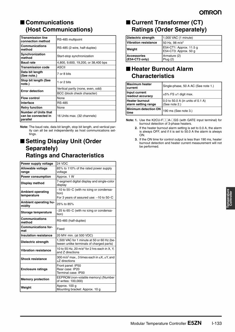
Communications(Host Communications)
Note: The baud rate, data bit length, stop bit length, and vertical par-ity can all be set independently as host communications set-tings.
Setting Display Unit (Order Separately) Ratings and Characteristics
Current Transformer (CT) Ratings (Order Separately)
Heater Burnout Alarm Characteristics
Note: 1. Use the K2CU-F@@A-@GS (with GATE input terminal) forburnout detection of 3-phase heaters.
2. If the heater burnout alarm setting is set to 0.0 A, the alarmis always OFF, and if it is set to 50.0 A the alarm is alwaysON.
3. If the ON time for control output is less than 190 ms, heaterburnout detection and heater current measurement will notbe performed.
Transmission lineconnection method RS-485 multipoint
Communications method RS-485 (2-wire, half-duplex)
Synchronizationmethod Start-stop synchronization
Baud rate 4,800, 9,600, 19,200, or 38,400 bps
Transmission code ASCII
Data bit length(See note.) 7 or 8 bits
Stop bit length (See note.) 1 or 2 bits
Error detectionVertical parity (none, even, odd)
BCC (block check character)
Flow control None
Interface RS-485
Retry function None
Number of Units that can be connected in parallel
16 Units max. (32 channels)
Power supply voltage 24 VDC
Allowable voltage range
85% to 110% of the rated power supply voltage
Power consumption Approx. 1 W
Display method 7-segment digital display and single-color display
Ambient operating temperature
−10 to 55×C (with no icing or condensa-tion)For 3 years of assured use: −10 to 50×C
Ambient operating hu-midity 25% to 85%
Storage temperature −25 to 65×C (with no icing or condensa-tion)
Communications method RS-485 (half-duplex)
Communications for-mat Fixed
Insulation resistance 20 MW min. (at 500 VDC)
Dielectric strength 1,500 VAC for 1 minute at 50 or 60 Hz (be-tween unlike terminals of charged parts)
Vibration resistance 10 to 55 Hz, 20 m/s2 for 2 hrs each in X, Y, and Z directions
Shock resistance 300 m/s2 max., 3 times each in ±X, ±Y, and ±Z directions
Enclosure ratingsFront panel: IP50Rear case: IP20Terminal case: IP00
Memory protection EEPROM (non-volatile memory) (Number of writes: 100,000)
Weight Approx. 100 gMounting bracket: Approx. 10 g
Dielectric strength 1,000 VAC (1 minute)
Vibration resistance 50 Hz, 98 m/s2
Weight E54-CT1: Approx. 11.5 gE54-CT3: Approx. 50 g
Accessories(E54-CT3 only)
Armature (2)Plug (2)
Maximum heatercurrent Single-phase, 50 A AC (See note 1.)
Input currentreadout accuracy ±5% FS ±1 digit max.
Heater burnoutalarm setting range
0.0 to 50.0 A (in units of 0.1 A)(See note 2.)
Minimum detection ON time 190 ms (See note 3.)
I-134 Modular Temperature Controller E5ZN
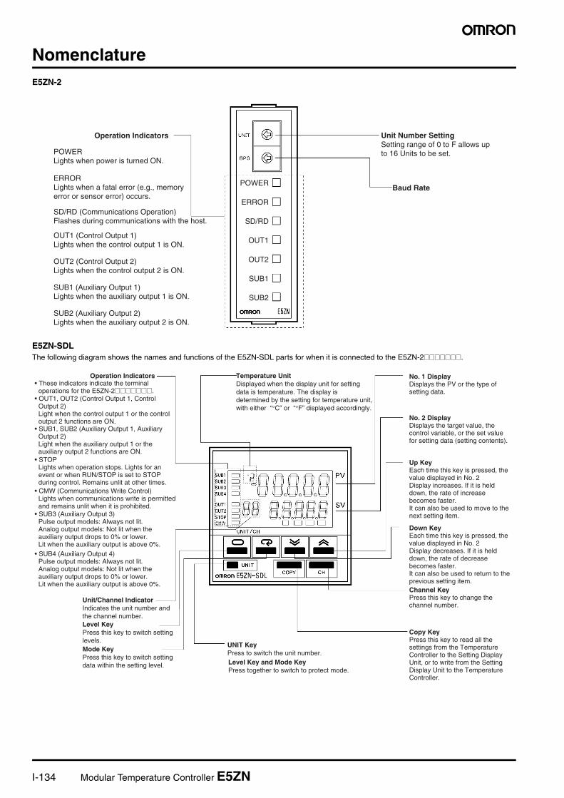
NomenclatureE5ZN-2
E5ZN-SDLThe following diagram shows the names and functions of the E5ZN-SDL parts for when it is connected to the E5ZN-2@@@@@@@.
Operation Indicators
POWERLights when power is turned ON.
ERRORLights when a fatal error (e.g., memory error or sensor error) occurs.
SD/RD (Communications Operation) Flashes during communications with the host.
OUT1 (Control Output 1) Lights when the control output 1 is ON.
OUT2 (Control Output 2)Lights when the control output 2 is ON.
SUB1 (Auxiliary Output 1)Lights when the auxiliary output 1 is ON.
SUB2 (Auxiliary Output 2)Lights when the auxiliary output 2 is ON.
POWER
ERROR
SD/RD
OUT1
OUT2
SUB1
SUB2
Unit Number SettingSetting range of 0 to F allows up to 16 Units to be set.
Baud Rate
No. 1 DisplayDisplays the PV or the type of setting data.
No. 2 DisplayDisplays the target value, the control variable, or the set value for setting data (setting contents).
Up KeyEach time this key is pressed, the value displayed in No. 2 Display increases. If it is held down, the rate of increase becomes faster.It can also be used to move to the next setting item.
Down KeyEach time this key is pressed, the value displayed in No. 2 Display decreases. If it is held down, the rate of decrease becomes faster.It can also be used to return to the previous setting item.Channel KeyPress this key to change the channel number.
Copy KeyPress this key to read all the settings from the Temperature Controller to the Setting Display Unit, or to write from the Setting Display Unit to the Temperature Controller.
UNIT KeyPress to switch the unit number.Level Key and Mode KeyPress together to switch to protect mode.
Mode KeyPress this key to switch setting data within the setting level.
Level KeyPress this key to switch setting levels.
Unit/Channel IndicatorIndicates the unit number and the channel number.
• SUB3 (Auxiliary Output 3) Pulse output models: Always not lit. Analog output models: Not lit when the auxiliary output drops to 0% or lower. Lit when the auxiliary output is above 0%.
• CMW (Communications Write Control) Lights when communications write is permitted and remains unlit when it is prohibited.
• STOPLights when operation stops. Lights for an event or when RUN/STOP is set to STOP during control. Remains unlit at other times.
• SUB1, SUB2 (Auxiliary Output 1, Auxiliary Output 2)Light when the auxiliary output 1 or the auxiliary output 2 functions are ON.
• OUT1, OUT2 (Control Output 1, Control Output 2)Light when the control output 1 or the control output 2 functions are ON.
• These indicators indicate the terminal operations for the E5ZN-2@@@@@@@.
Operation Indicators Temperature UnitDisplayed when the display unit for setting data is temperature. The display is determined by the setting for temperature unit, with either “°C” or “°F” displayed accordingly.
• SUB4 (Auxiliary Output 4) Pulse output models: Always not lit. Analog output models: Not lit when the auxiliary output drops to 0% or lower. Lit when the auxiliary output is above 0%.
Modular Temperature Controller E5ZN I-135
Tem
per
atu
reC
on
tro
ller
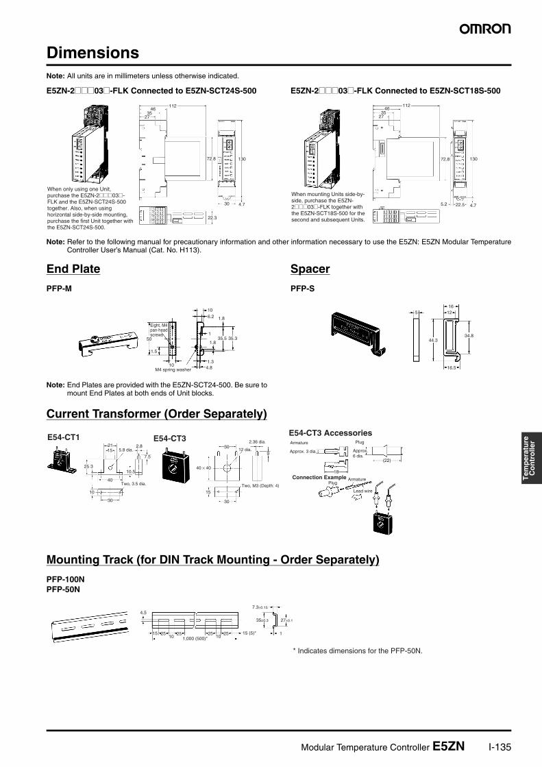
DimensionsNote: All units are in millimeters unless otherwise indicated.
E5ZN-2@@@03@-FLK Connected to E5ZN-SCT24S-500 E5ZN-2@@@03@-FLK Connected to E5ZN-SCT18S-500
Note: Refer to the following manual for precautionary information and other information necessary to use the E5ZN: E5ZN Modular TemperatureController User’s Manual (Cat. No. H113).
End Plate
PFP-M
Note: End Plates are provided with the E5ZN-SCT24-500. Be sure tomount End Plates at both ends of Unit blocks.
Spacer
PFP-S
Current Transformer (Order Separately)
Mounting Track (for DIN Track Mounting - Order Separately)
PFP-100NPFP-50N
When only using one Unit, purchase the E5ZN-2@@@03@-FLK and the E5ZN-SCT24S-500 together. Also, when using horizontal side-by-side mounting, purchase the first Unit together with the E5ZN-SCT24S-500.
11246
3527
72.8 130
22.3
30 4.7
When mounting Units side-by-side, purchase the E5ZN-2@@@03@-FLK together with the E5ZN-SCT18S-500 for the second and subsequent Units.
22.55.2 4.7
13072.8
11246
3527
50
11.5
10
106.2
1
1.8
1.34.8
35.5 35.3
1.8
Eight, M4 pan-head screws
M4 spring washer
1612
44.334.8
16.5
5
40 × 40
15
30
30
9
18
E54-CT1 E54-CT35.8 dia.
2.36 dia.
12 dia.
Two, 3.5 dia. Two, M3 (Depth: 4)
E54-CT3 AccessoriesArmature
Approx. 3 dia. Approx. 6 dia.
Plug
Connection ExamplePlug
Armature
Lead wire
30
10
25 3
2115
40
10.5
7.5
2.8
(22)
15 (5)*
7.3±0.15
35±0.3 27±0.1
1
* Indicates dimensions for the PFP-50N.
4.5
1,000 (500)*15 25 25 25 25
10 10
I-136 Modular Temperature Controller E5ZN
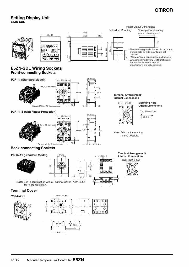
Setting Display UnitE5ZN-SDL
E5ZN-SDL Wiring SocketsFront-connecting Sockets
Back-connecting Sockets
Terminal Cover
48 × 48 6
(84)
63.7 14.2
44.8
× 4
4.8 45+0.6
0
45+
0.6
0
45+
0.6
0
60 m
in.
(48 × No. of Units – 2.5) +1.00
Individual Mounting Side-by-side MountingPanel Cutout Dimensions
• Vertical side-by-side mounting is not possible.(Allow sufficient space above and below.)
• The mounting panel thickness is 1 to 5 mm.
• When mounting several Units, make sure that the ambient tem-perature specifications are not exceeded.
35.4
4
3
7.84.5
30
35.4
4.5
4
7.8
5
1.2
3
40 ±0.240 ±0.2
P2F-11 (Standard Model)
P2F-11-E (with Finger Protection)
Two, 4.5-dia. holes
Eleven, M3.5 × 7.5 Sems screws
Two, 4.5-dia. holes
Eleven, M3.5 × 7.5 set screws
31.2 max.
70 max.
70 max.
Terminal Arrangement/ Internal Connections
Mounting Hole Cutout Dimensions
(TOP VIEW)
Two, M4 or 4.5 dia.
Note: DIN track mounting is also possible.
31.2 max.
50 max.
50 max.
45
45 4.516.3
25.6
6.2
8.7
4 7 3
6
P3GA-11 (Standard Model)Terminal Arrangement/Internal Connections
(BOTTOM VIEW)
27 dia.
Note: Use in combination with a Terminal Cover (Y92A-48G) for finger protection.
34
16.524.6 27.6
47.4
48 × 4847.7 × 47.7
Y92A-48G Twelve, 6.4 dia.
Modular Temperature Controller E5ZN I-137
Tem
per
atu
reC
on
tro
ller
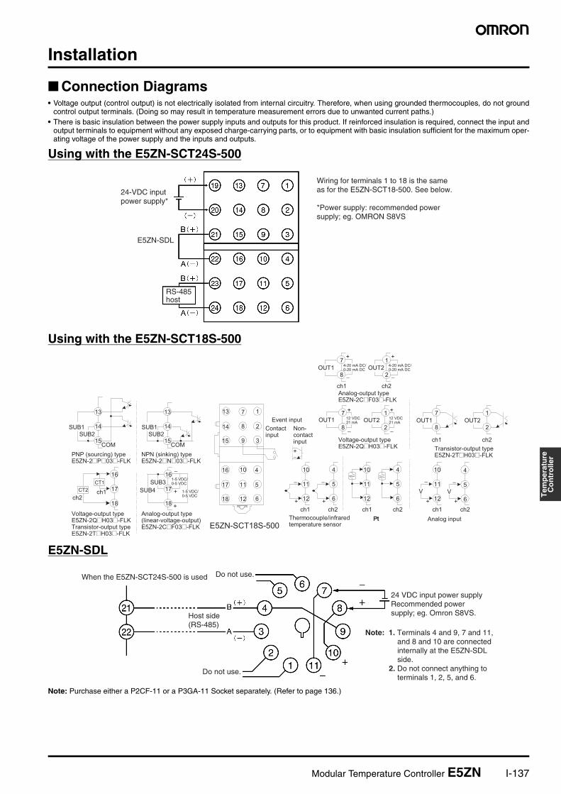
Installation
Connection Diagrams• Voltage output (control output) is not electrically isolated from internal circuitry. Therefore, when using grounded thermocouples, do not ground
control output terminals. (Doing so may result in temperature measurement errors due to unwanted current paths.)• There is basic insulation between the power supply inputs and outputs for this product. If reinforced insulation is required, connect the input and
output terminals to equipment without any exposed charge-carrying parts, or to equipment with basic insulation sufficient for the maximum oper-ating voltage of the power supply and the inputs and outputs.
Using with the E5ZN-SCT24S-500
Using with the E5ZN-SCT18S-500
E5ZN-SDL
Note: Purchase either a P2CF-11 or a P3GA-11 Socket separately. (Refer to page 136.)
24-VDC input power supply*
E5ZN-SDL
RS-485 host
Wiring for terminals 1 to 18 is the same as for the E5ZN-SCT18-500. See below.
*Power supply: recommended power supply; eg. OMRON S8VS
Pt
−
+
10
11
12
−
+
4
5
6
+
−
1
2
+
−
13 7 1
14
15
8
9
2
3
410
5
16
612
1117
18
V
−
+
4
5
6
V
−
+
10
11
12
4
5
6
10
11
12
1
2
13
14
15
13
14
15
7
8
7
8
+
−
+
−
7
8
1
2
CT1
CT2
16
17
18
-
16
17
18
+
−
+
−+
1-5 VDC/ 0-5 VDC
1-5 VDC/ 0-5 VDC
4-20 mA DC/ 0-20 mA DC
4-20 mA DC/ 0-20 mA DC
12 VDC 21 mA
12 VDC 21 mA OUT2
Pt
OUT2OUT1
Analog input
ch1 ch1ch1 ch2ch2ch2
ch1
OUT1
ch2
SUB1SUB2
COM
SUB1SUB2
COM
Event input
E5ZN-SCT18S-500
OUT2
ch2ch1
OUT1
ch1ch2
SUB3
SUB4
PNP (sourcing) type E5ZN-2@P@03@-FLK
Voltage-output type E5ZN-2Q@H03@-FLK Transistor-output type E5ZN-2T@H03@-FLK
NPN (sinking) type E5ZN-2@N@03@-FLK
Analog-output type (linear-voltage-output) E5ZN-2C@F03@-FLK
Contact input
Non-contact input
Thermocouple/infrared temperature sensor
Analog-output type E5ZN-2C@F03@-FLK
Voltage-output type E5ZN-2Q@H03@-FLK Transistor-output type
E5ZN-2T@H03@-FLK
When the E5ZN-SCT24S-500 is used Do not use.
Host side (RS-485)
Do not use.
24 VDC input power supplyRecommended power supply; eg. Omron S8VS.
Note: 1. Terminals 4 and 9, 7 and 11, and 8 and 10 are connected internally at the E5ZN-SDL side.
2. Do not connect anything to terminals 1, 2, 5, and 6.
I-138 Modular Temperature Controller E5ZN
Operation
CH
CH
CH
A
P
A
A
A
A
A
A
A
A
A
A
A
A
A
AP
P
alh10.2
°c
10
alh20.2
°c
10
hbuonu0
hbloffu0
mspuoffu0
eU-m1u0
a
a
a
a
a
a
a1ltoff10
a2ltoff10
a3ltoff10
inf0.010
pUadoffu0
a
isdpoffu0
initoffu0
eUnoneu0
restau0
al1nn-o10
al2nn-o10
alfa0.65u0
ol-h105.010
ol-l- 5.010
serooffu0
hbh0.110
a
ot-20u0
a
amoU0u0
sedu3u0
a
istp0u0
cjconu0
sprt010
a
a
a
a
a
a
a
a
a
a
a
a
a
a
a
a
a
al3nn-o10
alh30.2
°c
10
a
a
a
sub417u0
out25u0
a
sub12u0
a
sub27u0
a
sub312u0
a
tr1h1300u0
a
contnou0
a
tr3h1300u0
a
tr1l-200u0
a
tr2h1300u0
tr2l-200u0
a
a
tr3l-200u0
a
tr4h1300u0
a
a
ot-10u0
tr4l-200u0
in-l010
dp010
sl-h1300
°c
10
sl-l- 200
°c
10
cntlonof10
alt1210
cp210
alt2210
in-t0u0
in-h10010
d-ucu0
alt3210
c-cp210
oreUor-r10
out10u0
a
a
a
a
a
a
a
a
a
a
a
a
a
a
a
len7u0
sbit2u0
prtyeUenu0
sdwt20u0
a
a
a
a
a
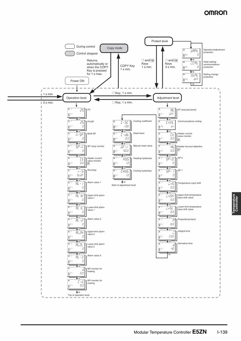
Multi-SP uses
SP ramp set value
Additional PV display
Operation after power ON
OUT1 transfer output upper limit
OUT1 transfer output lower limit
A
P
CH
ch2: ch1:in-h10010
in-h10010
in-h1000 2
:
:
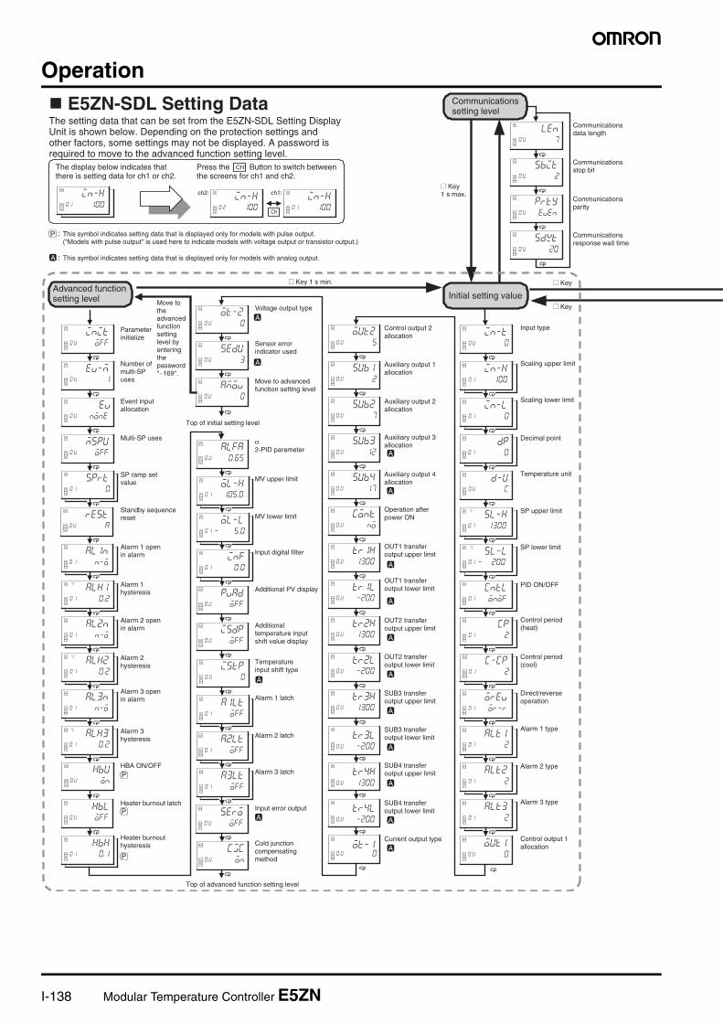
E5ZN-SDL Setting DataThe setting data that can be set from the E5ZN-SDL Setting Display Unit is shown below. Depending on the protection settings and other factors, some settings may not be displayed. A password is required to move to the advanced function setting level.
The display below indicates that there is setting data for ch1 or ch2.
CHPress the Button to switch between the screens for ch1 and ch2.
This symbol indicates setting data that is displayed only for models with pulse output. ("Models with pulse output" is used here to indicate models with voltage output or transistor output.)
This symbol indicates setting data that is displayed only for models with analog output.
Communications setting level
@ Key1 s max.
Communications data length
Communications stop bit
Communications parity
Communications response wait time
Advanced function setting level Move to
the advanced function setting level by entering the password "−169".
Parameter initialize
Number of multi-SP uses
Event input allocation
Standby sequence reset
Alarm 1 open in alarm
Alarm 1 hysteresis
Alarm 2 open in alarm
Alarm 2 hysteresis
Alarm 3 open in alarm
Alarm 3 hysteresis
HBA ON/OFF
Heater burnout latch
Heater burnout hysteresis
Voltage output type
Sensor error indicator used
Move to advanced function setting level
Top of initial setting level
α 2-PID parameter
MV upper limit
MV lower limit
Input digital filter
Additional temperature input shift value display
Temperature input shift type
Alarm 1 latch
Alarm 2 latch
Alarm 3 latch
Input error output
Cold junction compensating method
Top of advanced function setting level
@ Key 1 s min.
Control output 2 allocation
Auxiliary output 1 allocation
Auxiliary output 2 allocation
Auxiliary output 3 allocation
Auxiliary output 4 allocation
OUT2 transfer output upper limit
OUT2 transfer output lower limit
SUB3 transfer output upper limit
SUB3 transfer output lower limit
SUB4 transfer output upper limit
SUB4 transfer output lower limit
Current output type
Initial setting value
Input type
Scaling upper limit
Scaling lower limit
Decimal point
Temperature unit
PID ON/OFF
Alarm 1 type
Alarm 2 type
Alarm 3 type
Control output 1 allocation
SP upper limit
SP lower limit
Control period (heat)
Control period (cool)
Direct/reverse operation
@ Key
@ Key
Modular Temperature Controller E5ZN I-139
Tem
per
atu
reC
on
tro
ller
P
P
P
a
wtptoffu0
a
a
atoff10
ct0.010
hb0.010
sp-00
°c
10
sp-10
°c
10
cmwtonu0
oapt0u0
icptu0 0
a
a
a
a
a
250
°c
10
sp-m0
°c
10
ct0.010
m-sp010
r-sstop10
al-10
°c
10
al1h0
°c
10
al1l0
°c
10
al-20
°c
10
al2h0
°c
10
al2l0
°c
10
al-30
°c
10
o0.010
c-o0.010
25°c
10
ins0.0
°c
10
insh0.0
°c
10
insl0.0
°c
10
p8.0
°c
10
i23310
d4010
a
a
a
a
a
a
a
a
a
a
a
a
a
a
a
a
a
a
a
a
a
a
c-sc1.0010
c-db0.0
°c
10
of-r50.010
hys1.0
°c
10
chys1.0
°c
10
a
a
a
a
a
Run/stop
Alarm value 1
Upper-limit alarm value 1
Lower-limit alarm value 1
Alarm value 2
SP 0
SP 1
Temperature input shift
During control
Control stopped
1 s min.
3 s min.
Power ON
Operation level
PV
PV/SP
Multi-SP
SP ramp monitor
Heater current value monitor
Upper-limit alarm value 2
Lower-limit alarm value 2
Alarm value 3
MV monitor for heating
MV monitor for cooling
Top of operation level
Copy mode
Returns automatically or when the COPY Key is pressed for 1 s max.
COPY Key1 s min.
@ Key, 1 s min.
@ Key, 1 s min.
Cooling coefficient
Dead band
Manual reset value
Heating hysteresis
Cooling hysteresis
Start of adjustment level
Protect level
@ and a Keys1 s min.
@ and a Keys3 s min.
Adjustment level
AT execute/cancel
Communications writing
Heater current value monitor
Heater burnout detection
Upper-limit temperature input shift value
Lower-limit temperature input shift value
Proportional band
Integral time
Derivative time
Operation/adjustment protection
Initial setting/ communications protection
Setting change protection
I-140 Modular Temperature Controller E5ZN
Examples of FunctionsUsing as a Temperature Input Signal ConverterTransfer Output Types• The ten types of data shown below can be allocated for transfer
output using the control output 1 allocation, control output 2 alloca-tion, auxiliary output 3 allocation, and auxiliary output 4 allocation(initial setting level).
• Transfer output is supported by analog output models only.
Note: Control outputs 1 and 2 use current output and auxiliary out-puts 3 and 4 use linear voltage output.
Transfer Output Scaling• The range set by the transfer output upper limit and transfer output
lower limit (initial setting level) can be scaled to the output range forthe transfer output (4 to 20 mA DC or 0 to 20 mA DC for control out-puts 1 and 2, and to 1 to 5 VDC or 0 to 5 VDC for auxiliary outputs3 and 4).
• The scale can be expanded by setting a small range between thetransfer output upper and lower limits. Reverse scaling can be per-formed by setting the transfer output upper limit to a value smallerthan the transfer output lower limit. The following figure shows ascaling example where the heating control MV transfer output isscaled to 1 to 5 VDC.
Example: Scaling to 1 to 5 VDC
Reading Temperatures for Multiple E5ZN UnitsWith conventional models, if the present temperature is read frommultiple Temperature Controllers using host communications, thereare time differences in the process temperatures read from eachTemperature Controller, making it difficult to obtain concurrent data.
With the E5ZN, the PV hold function can be used to ensure that thedata is concurrent to within 500 ms.
PV HoldThe PV hold function temporarily stores the present temperature forthat moment as the PV hold value, when the "PV hold" operationcommand sent by host communications is received. (See fig. 1.)
Fig. 1
Note: 1. PV hold values are overwritten every time the "PV hold" op-eration command is executed. Once the PV hold valueshave been read for channels that require simultaneousreading of present temperatures, execute the next "PV hold"operation command.
2. The "PV hold" operation command cannot be executed andthe "PV hold value" cannot be read from the E5ZN-SDL Set-ting Display Unit.
3. When the power is turned OFF, the PV hold values changeto 0.
ch1 ch2Transfer output for ch1 set point Transfer output for ch2 set point
Transfer output for ch1 ramp set point Transfer output for ch2 ramp set point
Transfer output for ch1 process value Transfer output for ch2 process value
Transfer output for ch1 heating control MV
Transfer output for ch2 heating control MV
Transfer output for ch1 cooling control MV
Transfer output for ch2 cooling control MV
0
5
1
1008010
Transfer output (V)
Transfer output lower limit
Transfer output upper limit
Heating control MV (%)
Example 2: Displaying the ch2 Process Values on an External Meter Using Transfer OutputTemperature Controller: E5ZN-2C@F03P-FLK (current output,
platinum resistance thermometer input)Meter: K3MA-J 24 VAC/VDC (Process Meter)
Temperature Controller Settings:
Sensor input type (initial setting level): 2 (platinum resistance ther-mometer, 0.0°C to 100.0°C)Control output allocation 2 (initial setting level): 17 (process valuetransfer output for ch2)OUT2 transfer output upper limit (initial setting level): 100.0 (°C)OUT2 transfer output lower limit (initial setting level): 0 (°C)Current output type (initial setting level): 0 (4 to 20 mA DC)
Meter Setting Example:
Inputs for 4 to 20 mA DC are scaled to 0.0 to 100.0°C.Input type (initial setting level: in-t): 4 to 20 mA DC (4-20)Scaling input value 1 (initial setting level: inp.1): 4 mA (4.00)Scaling display value 1 (initial setting level: dsp.1): 0 (00000)Scaling input value 2 (initial setting level: inp.2): 20 mA (20.00)Scaling display value 2 (initial setting level: dsp.2): 100 (01000)Decimal point (initial setting level: dp): One decimal place (0000.0)
UNIT
BPS
POWER
ERROR
SD/RD
OUT1
OUT2
SUB1
SUB2
E5ZN
MAX/MIN LEVEL MODE SHIFT UP
Sheathed platinum resistance thermometer
B (white/black)
A (red)
Temperature Controller E5ZN-2C@F03P-FLK
4 to 20 mA DC output
Control output 2(current output)Terminals 1 and 2
ch2 input(platinum resistance thermometer input)Terminals 4, 5, and 6 B (black/white)
Input terminal (E5) −
Input terminal (E6) +
Process MeterK3MA-J 24 VAC/VDC
Host
(1) "PV hold" executed.
(3) "PV hold value" read.
Unit No. 0
Unit No. 15
(2) The present temperature is held.
(2) The present temperature for each E5ZN Unit from Units No. 0 to 15 is written simultaneously to PV hold values.
(3) The PV hold values are read in order, starting with Unit No. 0.
(1) "PV hold" is executed from the host computer.
Modular Temperature Controller E5ZN I-141
Tem
per
atu
reC
on
tro
ller
Precautions
General PrecautionsThe user must operate the product according to the performance specifications described in the operation manual.Before using the product under conditions that are not described in the manual or applying the product to nuclear control systems, rail-road systems, aviation systems, vehicles, combustion systems, med-ical equipment, amusement machines, safety equipment, and other systems, machines, and equipment that may have a serious influ-ence on lives and property if used improperly, consult your OMRON representative.Make sure that the ratings and performance characteristics of the product are sufficient for the systems, machines, and equipment, and be sure to provide the systems, machines, and equipment with dou-ble safety mechanisms.
Safety Precautions
Definition of Precautionary Information
!WARNINGThe above symbol indicates a situation that may result in injury orproperty damage.
Warnings
!WARNINGDo not allow metal fragments or lead wire scraps to fall inside thisproduct.These may cause electric shock, fire, or malfunction.
!WARNINGDo not use the product in locations subject to flammable or explo-sive gases. Doing so may result in explosion.
!WARNINGDo not touch any of the terminals while the power is ON. Doing somay result in electric shock.
!WARNINGProvide at least one power-interruption switch to ensure that thepower is OFF before wiring. Not doing so may result in electricshock.
!WARNINGTo maintain safety in the event of a product malfunction, alwaystake appropriate safety measures, such as installing an alarm ona separate line to prevent excessive temperature rises. If a mal-function prevents proper control, a major accident may result.
!WARNINGDo not attempt to disassemble, repair, or modify the product. Anyattempt to do so may result in malfunction, fire, or electric shock.
!WARNINGTighten screws to the specified torques given below.Loose screws may result in burning or malfunction.E5ZN-SCT@S-500: 0.40 to 0.56 N·mE5ZN-SDL: 0.74 to 0.90 N·m
!WARNINGSet all settings according to the control target of the product.If the settings are not appropriate for the control target, the productmay operate in an unexpected manner, resulting in damage to theproduct or accidents.
Application and OperatingEnvironment Precautions
Observe the following points to ensure safe operation.
1. Use and store the product within the specified temperature andhumidity ranges. Cool the product (e.g., using fans) where neces-sary.
2. Do not touch the electronic components or pattern of the PCB.Hold the product by the case.
3. To ensure proper heat dissipation, leave a space around the prod-uct. Do not block the product’s ventilating holes.
4. Use at the rated power supply voltage with the rated load.5. Be sure to connect terminals with the correct polarity.6. Perform wiring using crimp terminals of the specified size. (E5ZN-
SCT@S-500: M3.0, width 5.8 mm max.; E5ZN-SDL: M3.5, width7.2 max.)
7. Be sure to use wires satisfying the following specifications forconnection using bare wires.Power supply terminals: AWG 22 to 14Other terminals: AWG 28 to 16(Length of exposed part: 6 to 8 mm)
8. Do not connect anything to unused terminals.9. Ensure that the rated voltage is reached within 2 seconds of turn-
ing power ON.10.Allow 30 seconds’ warm-up time.11.Install the product as far away as possible from devices that gen-
erate strong, high-frequency noise and devices that generatesurges.
12.Keep wiring separate from high-voltage power lines or power linescarrying large currents. Do not wire in parallel with or togetherwith power lines.
13.Install switches or circuit-breakers so that the user can turn thepower OFF immediately, and indicate these accordingly.
14.Do not use the product in the following locations:• Locations subject to dust or corrosive gases (in particular, sul-
fide gas and ammonia gas)
• Locations subject to freezing or condensation
• Locations exposed to direct sunlight
• Locations subject to vibrations or shocks
• Locations subject to exposure to water or oil
• Locations subject to heat radiated directly from heating equip-ment
• Locations subject to intense temperature changes
15.When the Terminal Unit is separated from the Temperature Con-troller, under no circumstances touch the electrical componentsor apply shock to the Temperature Controller.
16.Do not use solvents to clean the product. Use commercial alco-hol.
17.After wiring is completed remove the dust-protection label to allowproper heat dissipation.
18.When mounting the Temperature Controller to the Terminal Unit,make sure that the hook on the side of the Temperature Controllerfacing the Terminal Unit is inserted properly.
19.Install the DIN track vertically.
Correct Use
Service LifeUse within the following temperature and humidity ranges:• Temperature: –10 to 55×C (with no icing or condensation)• Humidity: 25% to 85%
I-142 Modular Temperature Controller E5ZN
If the product is installed inside a control panel, the temperature around the product (and not the temperature around the control panel) must be kept below 55×C.With electronic devices like the E5ZN, the service life will depend not only on the number of switching operations performed by the relay but also on the service life of the internal electronic components. The service life of these components depends on the ambient tempera-ture; it will be shorter if the ambient temperature is high, and longer if the ambient temperature is low. For this reason, the service life of the product can be lengthened by keeping the inside of the E5ZN at a low temperature.If several Units are mounted side-by-side or are arranged vertically, the heat generated may cause the internal temperature of the Units to rise, reducing service life. To prevent this, take steps to ensure that the Units are cooled, such as installing fans.Ensure, however, that the terminals are not also cooled, otherwise correct temperature measurement will not be possible.
Measurement AccuracyWhen extending the lead wires for thermocouples, use a compensat-ing conductor appropriate for the type of thermocouple used.When extending the lead wires for platinum resistance thermome-ters, use lead wires with a low resistance, and make the resistance in the 3 lead wires equal.Mount the E5ZN horizontally.If significant errors occur, check that input compensation has been set correctly.
WaterproofingThe enclosure ratings are given below. Parts for which the enclosure rating is not clearly indicated, and parts with IP@0 ratings (where @ is not 0) do not have waterproof specifications.• Temperature Controller: IP00• Terminal Unit: IP00
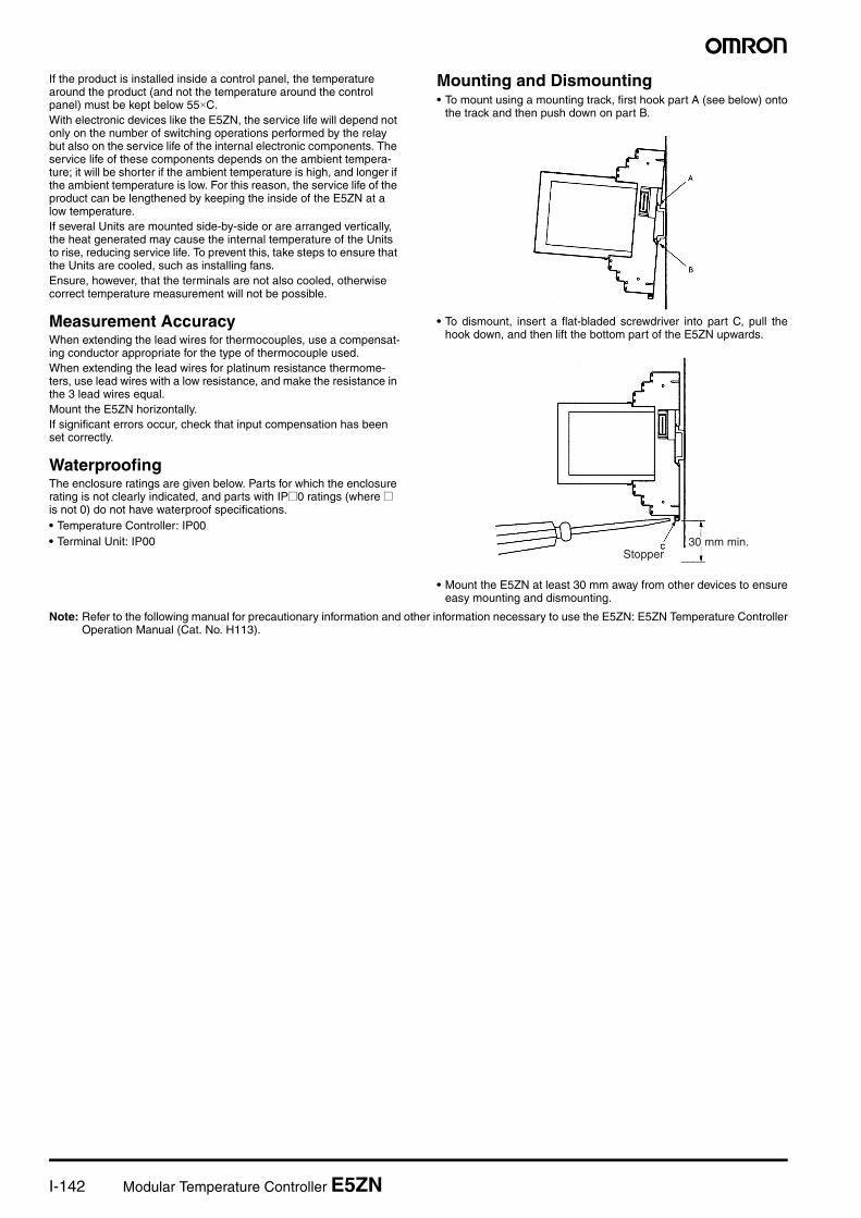
Mounting and Dismounting• To mount using a mounting track, first hook part A (see below) onto
the track and then push down on part B.
• To dismount, insert a flat-bladed screwdriver into part C, pull thehook down, and then lift the bottom part of the E5ZN upwards.
• Mount the E5ZN at least 30 mm away from other devices to ensureeasy mounting and dismounting.
Note: Refer to the following manual for precautionary information and other information necessary to use the E5ZN: E5ZN Temperature ControllerOperation Manual (Cat. No. H113).
Stopper30 mm min.
Modular Temperature Controller E5ZN I-143
Tem
per
atu
reC
on
tro
ller
Warranty and Limitations of Liability
WARRANTYOMRON's exclusive warranty is that the products are free from defects in materials and workmanship for a period of one year (or other period ifspecified) from date of sale by OMRON.
OMRON MAKES NO WARRANTY OR REPRESENTATION, EXPRESS OR IMPLIED, REGARDING NON-INFRINGEMENT, MERCHANTABILITY,OR FITNESS FOR PARTICULAR PURPOSE OF THE PRODUCTS. ANY BUYER OR USER ACKNOWLEDGES THAT THE BUYER OR USERALONE HAS DETERMINED THAT THE PRODUCTS WILL SUITABLY MEET THE REQUIREMENTS OF THEIR INTENDED USE. OMRON DIS-CLAIMS ALL OTHER WARRANTIES, EXPRESS OR IMPLIED.
LIMITATIONS OF LIABILITYOMRON SHALL NOT BE RESPONSIBLE FOR SPECIAL, INDIRECT, OR CONSEQUENTIAL DAMAGES, LOSS OF PROFITS, OR COMMER-CIAL LOSS IN ANY WAY CONNECTED WITH THE PRODUCTS, WHETHER SUCH CLAIM IS BASED ON CONTRACT, WARRANTY, NEGLI-GENCE, OR STRICT LIABILITY.
In no event shall the responsibility of OMRON for any act exceed the individual price of the product on which liability is asserted.
IN NO EVENT SHALL OMRON BE RESPONSIBLE FOR WARRANTY, REPAIR, OR OTHER CLAIMS REGARDING THE PRODUCTS UNLESSOMRON'S ANALYSIS CONFIRMS THAT THE PRODUCTS WERE PROPERLY HANDLED, STORED, INSTALLED, AND MAINTAINED AND NOTSUBJECT TO CONTAMINATION, ABUSE, MISUSE, OR INAPPROPRIATE MODIFICATION OR REPAIR.
Application Considerations
SUITABILITY FOR USEOMRON shall not be responsible for conformity with any standards, codes, or regulations that apply to the combination of products in the custom-er's application or use of the products.
At the customer's request, OMRON will provide applicable third party certification documents identifying ratings and limitations of use that applyto the products. This information by itself is not sufficient for a complete determination of the suitability of the products in combination with the endproduct, machine, system, or other application or use.
The following are some examples of applications for which particular attention must be given. This is not intended to be an exhaustive list of allpossible uses of the products, nor is it intended to imply that the uses listed may be suitable for the products.
• Outdoor use, uses involving potential chemical contamination or electrical interference, or conditions or uses not described in this catalog.• Nuclear energy control systems, combustion systems, railroad systems, aviation systems, medical equipment, amusement machines, vehicles,
safety equipment, and installations subject to separate industry or government regulations.• Systems, machines, and equipment that could present a risk to life or property. Please know and observe all prohibitions of use applicable to the products.
NEVER USE THE PRODUCTS FOR AN APPLICATION INVOLVING SERIOUS RISK TO LIFE OR PROPERTY WITHOUT ENSURING THAT THESYSTEM AS A WHOLE HAS BEEN DESIGNED TO ADDRESS THE RISKS, AND THAT THE OMRON PRODUCTS ARE PROPERLY RATEDAND INSTALLED FOR THE INTENDED USE WITHIN THE OVERALL EQUIPMENT OR SYSTEM.
I-144 Modular Temperature Controller E5ZN
In the interest of product improvement, specifications are subject to change without notice.
ALL DIMENSIONS SHOWN ARE IN MILLIMETERS.
To convert millimeters into inches, multiply by 0.03937. To convert grams into ounces, multiply by 0.03527.
Cat. No. H116-E1-02A