Embed Size (px)
Citation preview
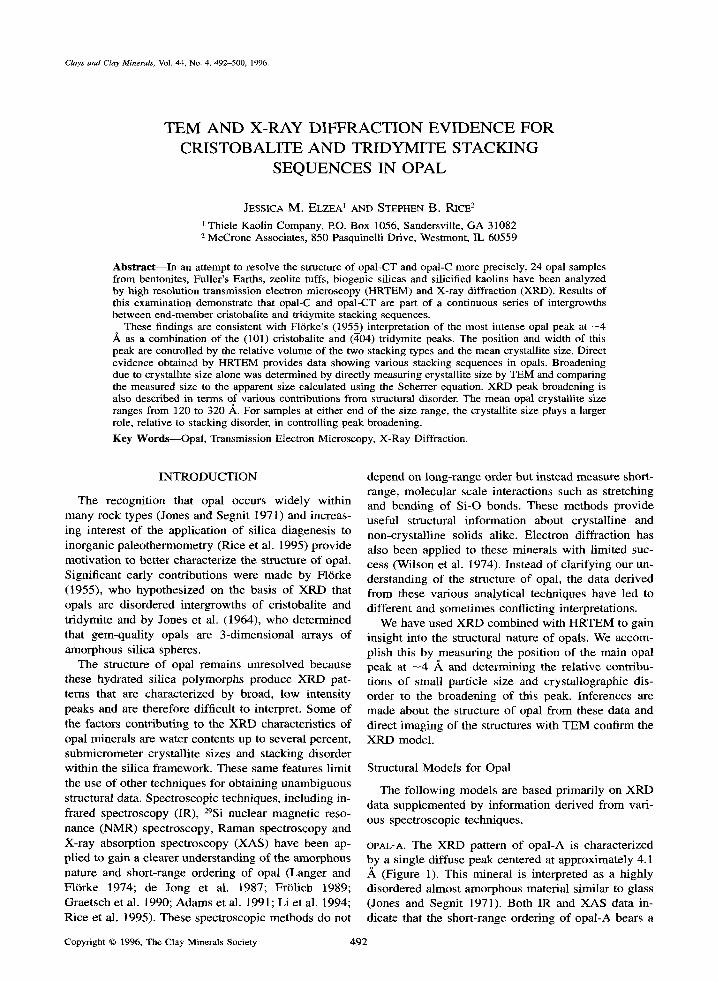
Clays and Clay Minerals, Vol. 44, No. 4, 492-500, 1996.
TEM A N D X-RAY DIFFRACTION EVIDENCE FOR CRISTOBALITE A N D TRIDYMITE STACKING
SEQUENCES IN OPAL
JESSICA M. ELZEA l AND STEPHEN B. RICE 2
Thiele Kaolin Company, P.O. Box 1056, Sandersville, GA 31082 2 McCrone Associates, 850 Pasquinelli Drive, Westmont, IL 60559
Abstract--In an attempt to resolve the structure of opal-CT and opal-C more precisely, 24 opal samples from bentonites, Fuller's Earths, zeolite tufts, biogenic silicas and silicified kaolins have been analyzed by high resolution transmission electron microscopy (HRTEM) and X-ray diffraction (XRD). Results of this examination demonstrate that opal-C and opal-CT are part of a continuous series of intergrowths between end-member cristobalite and tridymite stacking sequences.
These findings are consistent with Fl6rke's (1955) interpretation of the most intense opal peak at - 4 ,~ as a combination of the (101) cristobalite and (404) tridymite peaks. The position and width of this peak are controlled by the relative volume of the two stacking types and the mean crystallite size. Direct evidence obtained by HRTEM provides data showing various stacking sequences in opals. Broadening due to crystallite size alone was determined by directly measuring crystallite size by TEM and comparing the measured size to the apparent size calculated using the Scherrer equation. XRD peak broadening is also described in terms of various contributions from structural disorder. The mean opal crystallite size ranges from 120 to 320 A.. For samples at either end of the size range, the crystallite size plays a larger role, relative to stacking disorder, in controlling peak broadening.
Key Words--Opal, Transmission Electron Microscopy, X-Ray Diffraction.
INTRODUCTION
The recognition that opal occurs widely within many rock types (Jones and Segnit 1971) and increas- ing interest of the application of silica diagenesis to inorganic paleothermometry (Rice et al. 1995) provide motivation to better characterize the structure of opal. Significant early contributions were made by F16rke (1955), who hypothesized on the basis of XRD that opals are disordered intergrowths of cristobalite and tridymite and by Jones et al. (1964), who determined that gem-quality opals are 3-dimensional arrays of amorphous silica spheres.
The structure of opal remains unresolved because these hydrated silica polymorphs produce XRD pat- terns that are characterized by broad, low intensity peaks and are therefore difficult to interpret. Some of the factors contributing to the XRD characteristics of opal ininerals are water contents up to several percent, submicrometer crystallite sizes and stacking disorder within the silica framework. These same features limit the use of other techniques for obtaining unambiguous structural data. Spectroscopic techniques, including in- frared spectroscopy (IR), 29Si nuclear magnetic reso- nance (NMR) spectroscopy, Raman spectroscopy and X-ray absorption spectroscopy (XAS) have been ap- plied to gain a clearer understanding of the amorphous nature and short-range ordering of opal (Langer and FliSrke 1974; de Jong et al. 1987; Frt~lich 1989; Graetsch et al. 1990; Adams et al. 1991; Li et al. 1994; Rice et al. 1995). These spectroscopic methods do not
depend on long-range order but instead measure short- range, molecular scale interactions such as stretching and bending of Si-O bonds. These methods provide useful structural information about crystalline and non-crystalline solids alike. Electron diffraction has also been applied to these minerals with limited suc- cess (Wilson et al. 1974). Instead of clarifying our un- derstanding of the structure of opal, the data derived from these various analytical techniques have led to different and sometimes conflicting interpretations.
We have used XRD combined with HRTEM to gain insight into the structural nature of opals. We accom- plish this by measuring the position of the main opal peak at --4 ,~ and determining the relative contribu- tions of small particle size and crystallographic dis- order to the broadening of this peak. Inferences are made about the structure of opal from these data and direct imaging of the structures with TEM confirm the XRD model.
Structural Models for Opal
The following models are based primarily on XRD data supplemented by information derived from vari- ous spectroscopic techniques.
OPAL-A. The XRD pattern of opal-A is characterized by a single diffuse peak centered at approximately 4.1 ,~ (Figure 1). This mineral is interpreted as a highly disordered almost amorphous material similar to glass (Jones and Segnit 1971). Both IR and XAS data in- dicate that the short-range ordering of opal-A bears a
Copyright �9 1996, The Clay Minerals Society 492

Vol. 44, No. 4, 1996 TEM and XRD for cristobalite and tridymite stacking in opal 493
c -
o o
o ,,c l/ c j / c c A
10 15 20 25 30 35 40
Degrees, 2-theta Figure 1. XRD scans for opal-A, opal-CT and opal-C. Quartz (Q) impurities are present within opal-A.
resemblance to cristobalite and tridymite. For exam- ple, the IR spectrum of opal-A from the Monterey For- marion has an absorption band near 470 cm -1, which is close to absorption bands assigned to Si-O bending modes for both tridymite and cristobalite (Rice et al. 1995). Similarly, the XAS spectrum of opal-A exhibits peaks reflecting crystal chemical parameters attribut- able to cristobalite (Li et al. 1994).
OPAL-CT. The diffraction pattern of opal-CT contains four moderately broad peaks that coincide closely with the positions of the four most intense et-cristobalite diffraction maxima (Figure 1). The most intense opal-CT reflection may occur anywhere from 4.07 to 4.10 ,~ and exhibits a range of peak widths (Elzea et al. 1994). The breadth and position of this peak are a consequence of the combination of two unresolved peaks, the ct-cristobalite (101) and et-tridymite (404), as well as non-Bragg diffraction phenomena derived from the intergrowth of c~-cristobalite and ct-tridymite- like layers. In some cases, a secondary peak with a position close to the (404) ct-tridymite line is observed on the high angle side of the main opal-CT reflection. However, none of the opals studied for this investi- gation exhibited this secondary peak. These data sug-
gest that opal-CT has a cristobalite-like structure with varying degrees of stacking disorder leading to the ap- pearance of tridymite reflections. F16rke (1955) pro- posed that this mineral is comprised of sheets of six- membered rings of silica tetrahedra stacked within ran- dom intergrowths of cristobalite (ABCABC . . . ) and tridymite (A' . . . ) sequences where B is an A-layer shifted by a/3 and C is an A-layers shifted by -a /3 , and A' is an A-layer rotated 180 ~
Wilson et al. (1974) offered another interpretation based on electron diffraction patterns and IR spectra from two opal samples. They concluded that opal-CT is essentially disordered tridymite. This conclusion is based partially on the similarity between the IR spectra of opal-CT and tridymite. Jones and Segnit (1971) also noted that the IR spectrum of opal-CT more closely resembles e-tridymite than c~-cristobalite, but they ar- gued that this observation is consistent with the one- dimensional stacking disorder model proposed by Flrrke (1955). Rice et al. (1995) also observed a sim- ilarity between the spectroscopic signatures of opal-CT and tridymite.
A reinterpretation of the structure of opal-CT is giv- en by de Jong et al. (1987), who combined XRD with 295i nuclear magnetic resonance spectroscopy to probe the structure of natural and synthetic opal. The NMR spectrum of opal-CT resembles amorphous silica much more than tridymite or cristobalite. This finding led the authors to conclude that long-range ordering of the oxygen array had taken place but that the Si atoms had not reached their equilibrium positions. They proposed three structural models for opal-CT that are consistent with both XRD and NMR data: 1) disordered cristobalite; 2) cristobalite with tridymite stacking sequences; or 3) tridymite with cristobalite stacking faults. Adams et al. (1991), using the same method, were unable to distinguish opal-CT from amorphous silica (opal-A).
Guthrie et al. (1995) used the WILDFIRE program to simulate XRD patterns for opal-CT and compared them to several natural opal-CT specimens. They found that a good match was obtained by modeling opal-CT as interstratified layers of cristobalite and trid- ymite and that some opal-CT is best modeled as a random interstratification and some opal-CT is best modeled as a partially ordered interstratification.
OPAL-C. Opal-C produces an XRD pattern that is al- most identical to that of ct-cristobalite in terms of peak position, number of reflections and peak intensity (Fig- ure 1). However, both peak broadening and a slightly larger d-spacing provide indirect evidence for the pres- ence of tridymite stacking disorder within this opal polymorph (Elzea et al. 1994). Opal-C has been inter- preted as more ordered than opal-CT because it has sharper, more intense peaks.

494 Elzea and Rice Clays and Clay Minerals
Table 1. Sample description and summary of XRD data for opal polymorphs.
Name/location
- 4 A Peak -- Sample
Rock type Position (&) Width (~ #
Australia Lovelock, NV Upton, WY Mowry FM, WY Yell. C. Bed, WY Blue C. Bed, WY New Castle, WY Upper Bed, WY D-Bed, WY Texas Chalk Hills, ID Turkey Mozambique Utah Porters Creek Twiggs Fro, GA Monterey Fm, CA Leg 129 Leg 129 Wrens, GA Wrens, GA Lovelock, NV Lovelock, NV Lovelock, NV
Bentonite 4.043 0.263 AUST Bentonite 4.054 0.492 LNV Bentonite 4.040 0.332 UPWY Bentonite 4.043 0.405 LMWY Bentonite 4.033 0.230 YCWY Bentonite 4.038 0.269 BCWY Bentonite 4.036 0.321 NCWY Bentonite 4.043 0.355 UBWY Bentonite 4.044 0.249 DBWY Bentonite 4.088 0.684 TEX Bentonite 4.070 0.778 CHID Bentonite 4.082 0.885 TRK Bentonite 4.054 0.480 MOZ Fuller's Earth 4.053 0.567 UTH Fuller's Earth 4.093 0.574 PC Fuller's Earth 4.106 0.985 TCG Diatomaceous Earth 4.083 0.811 MCA Porcellanite 4.102 0.757 L 1291 Porcellanite 4.102 0.763 L1292 Silicified Limestone 4.108 0.654 WSL Flint Kaolin 4.106 0.975 SNFC Zeolite Tuff 4.067 0.808 LZEO1 Zeolite Tuff 4.077 - - LZEO2 Zeolite Tuff 4.069 0.607 LZEO3
S A M P L E S
Twenty-four samples of natural opal f rom bentonite, Fuller 's earth, silicified kaolin, porcellanite, zeoli t ized tuff and diatomaceous sediments were analyzed by X R D (Table 1). Twelve o f the 24 samples were further analyzed by HRTEM. In addition, X R D data were col- lected f rom 4 standards (Table 2). The amount of opal for this suite of samples is est imated to range f rom approximately 20% by vo lume in the bentonites and other clay deposits to 90% by vo lume for the purer dia tomaceous earths. The opals examined in this study occur as secondary minerals deposited under a wide range of geochemical condit ions and represent both volcanogenica l ly and biogenical ly der ived opal -CT and opal-C.
M E T H O D S A N D P R O C E D U R E S
All samples were dried and pulver ized to an average particle size of approximately 10 to 30 txm. No attempt was made to separate the opal f rom the matr ix min- erals because the presence of non-opal phases did not affect the quality of the X R D analysis for our purpos-
Table 2. SiO 2 polymorph standards.
Mineral Source
Tridymite (ty-27) NIOSH c~-Cristobalite (cb-25) NIOSH ~x-Cristobalite (Gem Dugout) Gem Dugout ot-Cristobalite (SRM 1879) NIST
es. Smecti tes often interfered with imaging the opal by TEM. Treatment to r emove clays was tried for two specimens, but it only marginal ly improved imaging and introduced the potential for altering the opal.
The powders were packed into sample holders and scanned on a Siemens D5000 X-ray diffractometer f rom 17.5 to 25 ~ using C u K a radiation, a 0.01 ~ step size and a 10 s per step data col lect ion time. The Siemens peak fitting routine (FIT) was used to fit the patterns with either a Lorentzian or pseudo-Voigt func- tion, and peak positions were determined f rom the fit- ted data using the posit ion of the quartz (101) peak as an internal standard. Because the main opal peak can- not be resolved into two, it was model led for fitting purposes as one peak. Peak width was calculated by measuring the width at half height ( F W H M ) and sub- tracting 0.0036 ~ to correct for instrumental broad- ening. The corrected peak width was assumed to rep- resent broadening caused by particle size and disorder.
Actual crystall i te size was measured by TEM. The Scherrer equation was used to calculate F W H M ex- pected for that average crystall i te size. The amount of broadening attributable to disorder was calculated us- ing the relation:
BE 2 = Bs 2 + BI 2 + BD 2 Ill
where: BE = exper imental ly observed broadening (FWHM); B s (measured by TEM) = broadening due to small particle size; BI = broadening due to instru- mental effects; and BD = disorder broadening.

Vol. 44, No. 4, 1996 TEM and XRD for cristobalite and tridymite stacking in opal 495
Figure 2. Width of the main opal peak (BE) expressed as full-width at half maximum (FWHM) in ~ Synthetic cristobalite and tridymite reference materials are also plotted.
TEM samples were prepared by dispersing the pow- der in alcohol and depositing it on carbon coated cop- per TEM grids. Crystallite sizes were directly mea- sured from negatives obtained on a JEOL 4000FX op- erated at 400 kV with an electron optical magnification of 200,000 x. These conditions were chosen to min- imize beam damage but yield a high enough resolution to allow observation of extremely fine details. Individ- ual crystallites, viewed using conventional bright-field imaging and recognized based primarily upon phase and amplitude contrast, were measured for all samples except the zeolite tuffs. The longest dimension was recorded as the crystallite diameter. Because the opals are typically close to equidimensional, this provided a consistent way of measuring each sample. Mean crys- tallite sizes were determined from the measurement of approximately 550 crystallites per sample.
TEM was also used to obtain lattice images. For these observations an effort was made to minimize beam damage to the sample by dessicating the samples within the high vacuum of the microscope for several hours prior to examination and by limiting the electron dose during observation and image exposure. Image simulations were carried out using the MacTempas multislice program (Total Resolution, Berkeley, CA).
RESULTS AND DISCUSSION
The opals examined in this study exhibit a contin- uous range of spacings from approximately 4.03 to 4.11 ,~ and peak widths from 0.2 to 1 ~ (Table 1). Opals with d-spacings closest to the position of the (101) cristobalite peak exhibit the narrowest diffrac- tion maxima, and samples with maxima closest to the tridymite, preserve structural information 404 peak po- sition display the broadest diffraction maxima (Figure 2). According to the Jones and Segnit (1971) classifi- cation scheme, these opals fall into the opal-C and opal-CT categories. However, a precise division be- tween these two polymorphs is not clear from our data. Instead, we suggest that opals are more accurately de- scribed as a continuous series extending from the cris- tobalite toward a hypothetical tridymite-like end-mem- ber phase.
F1Orke's interpretation of the structure of these poly- morphs predicts that opals with main maxima close to either the cristobalite or tridymite peak position will exhibit less broadening than will opals with peak po- sitions intermediate between the two end-members. The small amount of broadening exhibited by the opals with peak positions close to that of cristobalite

496 Elzea and Rice Clays and Clay Minerals
Table 3. CrystaUite size data collected by TEM (mean size) ~ 400 and XRD (Scherrer size). (ff
M e a n Scherrer N S a m p l e # s ize , .~ s ize . ~. B s B o %B~ % B D
AUST 320 342 0.284 0.000 100 0 LNV 297 183 0.306 0.385 44 56 UPWY 311 271 0.292 0.158 65 35 MOZ 279 187 0.317 0.360 47 53 TCG 117 91 0.767 0.618 55 45 MCA 262 111 0.349 0.737 32 68 L1291 279 119 0.326 0.683 32 68 L1292 257 118 0.350 0.678 34 66 WSL 250 137 0.352 0.551 39 61 SNFC 134 95 0 .671 0.707 49 51 LZEO 1 > 1000 111 0.009 0.808 l 99 LZEO3 >1000 148 0.009 0.607 1 99
are consistent with this model. But, the samples with maxima close to the tridymite peak show more peak broadening than would be expected from the presence of a small amount of cristobalite domains. This peak broadening may be due to particle size. However, ran- dom interstratification of the two layer types cannot be discounted as a contributor.
To test the hypothesis that crystallite size influences peak broadening, the broadening caused by small crys- tallite size alone was determined by directly measuring crystallite size with the TEM and solving the Scherrer equation for peak width. An apparent crystallite size was also calculated from the XRD data and compared to that obtained by TEM. According to our TEM mea- surements, the opals in all samples, except for LZEO1 and LZEO3, have mean crystallite sizes ranging from approximately 120 to 320 A as compared to 91 to 342
calculated from XRD patterns (Table 3). Crystallite sizes calculated from XRD patterns are, except for one sample, smaller than crystallite sizes measured by TEM. This discrepancy between calculated and mea- sured crystallite sizes suggests that there are contri- butions to peak broadening other than crystallite size.
Opals with 4 .~ peak d-spacings closest to the trid- ymite (2~04) peak position tend to have the smallest mean crystallite sizes as measured by TEM (Figure 3), suggesting that the relative contribution to broadening by crystallite size alone varies. Peak broadening caused by crystallite size (Bs) ranges from approxi- mately 0.3 to 0.7 ~ whereas peak broadening caused by disorder (Bn) ranges from approximately 0.0 to 0.8 ~ (Table 3). For the majority of samples, crystallite size (Bs) accounts for 32 to 50% of the total broad- ening (Table 3). The percentage of peak broadening attributable to disorder (BD) varies from 0 to 99% (Fig- ure 4).
The relative impact of disorder on line broadening is small for samples that exhibit d-spacings close to the cristobalite end-member (Figure 4). Conversely, line broadening due to disorder is greatest for samples
3 0 0
o t,-,,
m"O
�9 �9
2 0 0
cU
o l i i , t
1 0 0 ' , I , I
4.02 4.04 4.06 4.08 4.10 4.12
d-spacing, A Figure 3. Mean crystallite sizes as measured by TEM for 10 opal specimens plotted against the d-spacing of the main opal peak measured by XRD.
with d-spacings intermediate to the cristobalite (101) and tridymite (ZL04) peak positions. These observations support a structural model for opal-CT that is consis- tent with the one originally proposed by F/6rke (1955). Opal-CT consists of intergrowths of cristobalite and tridymite domains that lead to varying amounts of line broadening depending upon the relative volumes of cristobalite and tridymite domains. The frequency of stacking changes also influence the broadening by re- ducing the effective domain sizes and contributing to the non-Bragg components recorded within the dif- fraction patterns. According to this model, opals with a proportionally higher volume of cristobalite or trid- ymite layers will have more narrow peaks that shift toward the position of the most abundant end-member. This model further predicts that opals with similar vol- umes of cristobalite and tridymite layers will have broader peaks that fall between the cristobalite and tridymite peak positions. Thus, the model predicts that BD versus the position of the main opal peak will be an inverted parabola.
The only inconsistency between the proposed model and the data plotted in Figure 5 is the asymmetry of the curve close to the tridymite (2[04) peak position. The model predicts less disorder broadening close to the position of this peak than is observed. There may be several explanations for this higher than expected degree of disorder broadening. The presence of cris- tobalite domains could be a major factoi: There also may be several types of disorder. For example, A1 sub- sfitution for Si and/or cation substitution, variable OH structural positions, or variable H20 content within the tridymitic phase. Errors associated with either the TEM crystallite size measurements or the calculation of the peak width from the XRD data are also possible. These more tridymitic opals tend to have much broad- er, less intense peaks than the more cristobalitic end-

Vol. 44, No. 4, 1996 TEM and XRD for cristobalite and tridymite stacking in opal 497
cO (D t -
!
04
r (D
"O
0~ e (b
Cr) t--
m m t - O
"O t~ 2
m
1 . 5 "
1.0"
0.5
0.0
[] Disorder �9 Crystallite size
4.067
4.067
4.083 4.102 4.102
/
4.106 4.106
UPWY AUST MOZ LNV LZE01 LZEO3 MCA L1292 L1291 TCG SNFC WSL
Sample Figure 4. Relative contribution of crystallite size and disorder (BD) to the total breadth (BE) measured for 12 opal samples. See text for explanation of how these values were determined. Values over bars are d-spacings.
members, leading to errors in the FWHM measure- ment and increased error during the peak fitting. Fi- nally, the calculated Scherrer size relates to the size of the coherent diffraction domain rather than the actual size of the crystallite. For example, consider a 100 ,~ crystal that has a very thin cristobalite layer in the middle. The effective size, as seen by diffraction, is a --<50 _A domain. Thus, the size broadening could ex- ceed predicted size measurements alone for specimens having predominantly tridymite domains with only mi- nor cristobalite layers or other stacking faults.
To obtain more direct evidence for the presence of two layer types in opal-CT, HRTEM images were re- corded for several samples. These images are inter- preted in terms of idealized coherent stackings of tri- gonal silica nets and give direct evidence that opal-CT is comprised of interlayered cristobalite and tridymite stacking sequences.
Figure 6a shows a high resolution micrograph of a portion of an opal crystallite from the Wyoming ben- tonite. To improve the quality of the experimental im- age, fast Fourier transform (FFr) filtering was per- formed to remove non-periodic components resulting from the carbon support, radiation damage and shot noise. A mask filter was then applied to the FFT and an inverse transform was carried out (Figure 6b). Cau-
tion was taken to avoid imposing periodicities on regions containing none to begin with. The 4 ,~ inter- layer spacing and the 72 ~ angle between the intersect- ing sets of lattice fringes agree with the A B C A B C . . . stacking sequence of cristobalite as demonstrated by agreement with the simulated image of the (100) pro- jection of a-cristobalite (Figure 6c). This is the most commonly observed periodic image for the opal-C samples.
The opal-C samples also contain noncrystalline ma- terial. It is not known to what extent this is genuinely non-crystalline as opposed to crystallites whose long- range order has been disrupted by beam damage. The XRD patterns, even of opal-C, consistently contain a broad, low intensity hump suggestive of a non-crys- talline component such as opal-A. The TEM data were ambiguous.
High resolution electron microscope images were obtained for several samples with main peak positions greater than 4.04 ,~: Monterey opal-CT (MCA, 4.083 A), silicified kaolin (SNFC, 4.106 /~) and silicified limestone (WSL, 4.108 A). In contrast to the opal-C from bentonite, these all included cristobalite stacking but also showed substantial departure from the ideal cristobalite stacking in many images. Examples are presented here for opals from the silicified kaolin.

498 Elzea and Rice Clays and Clay Minerals
El f13 V
t - i m
r
cD
9 ..Q
t _
(D
0 .in E3
1.0
0.8
0.6
0.4
0.2
0.0 4.02
= |.,- o LZE01 ~ SNFC
/ _ ' ~ L1291 �9
. . . . TCG
z
O UPWY y = - 5 6 6 0 + 2770}< - 3 3 9 ~ 2
A U S T l u l l �9 I . , , w I v I n
l i t
4.04 4.06 4.08 4.10
i
= 0
: E u ~ = ' 0 ' N
~ 2 = 0 . 8 9
I
4.12
d-spacing, A Figure 5. Contribution of disorder broadening (BD) plotted against d-spacing of main opal peak.
Figure 7a shows an experimental lattice image of a portion of an opal crystallite characterized by cristo- balite stacking at the top, tridymite stacking in the middle, and cristobalite at the bottom. The Fourier fil- tered version is shown in Figure 7b, and the stacking schematically is depicted in Figure 7c. Image simula- tion for the tridymite (110) projection (Figure 7b, in- set) demonstrates agreement between calculated and
experimental images. The schematic version applies mainly to the right side of the image. A close look at the tridymite region (Figure 7b) reveals a reversal in the direction of the vertical "zig-zag" pattern near the middle produced by adjacent tridymite layers. On the right side of the image, the tfidymite stacking order is AA'A and on the left side stacking order changes to A ' A A ' . There is a dislocation defect approximately
a b c
Figure 6. a) TEM lattice image of opal crystallite within Wyoming bentonite (UPWY); b) Fourier filtered version of image in (a); c) structure drawing of cristobalite stacking for comparison. Inset in (b) is a simulation of the (100) projection of ct-cristobalite.

Vol. 44, No. 4, 1996 TEM and XRD for cristobalite and tridymite stacking in opal 499
a b c
Figure 7. a) Lattice image of opal crystallite in silicified kaolin (SNFC); b) cristobalite stacking is evident in the top and bottom of the Fourier filtered image; c) schematic drawing for stacking observed on the right half of the image. Inset in (b) is a simulation of the (110) projection of high-tridymite.
where this reversal meets the cristobalite stacking se- quence. Its termination is indicated by a dot at the bottom central portion of the image. Other distur- bances, such as in the lower left, are difficult to inter- pret because they probably include differences through the thickness of projection.
Figure 8a shows an experimental image of an opal crystallite whose cristobalite stacking is interrupted by several planar boundaries. Fourier filtering is vital for correct interpretation. What appear from the experi- mental image to be four or five twin boundaries are indicated to be two minimum tridymite units (AA'A- type repeats) occurring between cristobalite sequences, one of which has a twin boundary. It is obvious how the presence of tridymite domains would strongly af- fect the diffraction behavior, but there is also a poten- tial impact if opal crystallites were to be polysynthet- ically twinned. The schematic drawing in Figure 8c shows how cristobalite twins relate to one another across the twin boundary. The stacking of adjacent hexagonal nets on either side of the twin plane is iden-
tical to the fundamental increment for ideal tridymite. As the twinning density increases, accompanied by a cristobalite domain size decrease, the specimen will appear more like a disordered tridymite.
It is difficult to estimate how much of each stacking type is present within rock samples on the basis of a few lattice images. Furthermore, based on opal-C im- ages and intragrain comparisons from the opal-CT im- ages, cristobalite stacking is better preserved during imaging than the tridymite stacking. However, in spite of these caveats, we infer from our survey of opal-CT samples that substantial cristobalite stacking occurs, even for opal d-spacings of approximately 4.1 ,~. There is probably sufficient disorder of this type to create XRD peak broadening that is measurable. This is in contrast to the opal-C end of the series, in which negligible tridymite stacking occurs. The broadening expected from a 40 to 80 .A domain thickness, a rea- sonable estimate for the silicified kaolin, could also be invoked to explain much of the measured B o. Other types of disorder due to factors such as A1 substitution
a b c
Figure 8. a) Lattice image of opal crystallite in silicified kaolin (SNFC) showing intergrown cristobalite and tridymite; b) Fourier filtered image; c) structure drawing of mixed cristobalite and tridymite stacking including a twin plane.

500 Elzea and Rice Clays and Clay Minerals
for Si and associa ted ca t ion subs t i tu t ion requi red to ma in ta in charge balance, impur i t ies and wate r con- tents, wou ld not mani fes t themse lves in images . Dis- order defects such as s h o w n in F igure 7b are also can- didates for mod i fy ing the ma in di f f ract ion max ima , bu t es t imates of the i r f r equency are speculat ive. Al- t hough t r idymite s tacking is ve ry c o m m o n , perhaps even p reva len t for opals w h o s e d-spac ings are near 4.1 A, we h a v e not yet encoun te red wha t cou ld b e legiti- mate ly cal led opal-T.
S U M M A R Y
We have s h o w n that the opal p o l y m o r p h s represen t a con t inuous series of d isordered in te rgrowths be t w een e n d - m e m b e r cr is tobal i te and t r idymi te s tacking se- quences . By us ing m e a n crysta l l i te sizes direct ly mea- sured f rom T E M images , we were able to d i s t inguish the X R D l ine b roaden ing due to crysta l l i te size f rom that due to structural disorder. The resul t ing data show that opals wi th 4 ]k peaks close to the pos i t ion of the cr is tobal i te (101) peak have m i n i m u m disorder b road- en ing and opals wi th 4 ~ peaks in b e t w e e n the posi- t ions of the cr is tobal i te (101) and t r idymi te (2[04) peak posi t ions exhib i t the m a x i m u m disorder b roadening . The opals wi th X-ray m a x i m a c loses t to the t r idymi te (404) peak, exh ib i t a greater degree o f d isorder b road- en ing than expec ted f rom X R D and s ize-correc ted data. At the t r idymite end, it is l ikely tha t a combi - na t ion o f factors such as cr is tobal i te s tacking and twin- ning, d o m a i n size cons idera t ions and other types of disorder, are respons ib le for the b roaden ing .
A C K N O W L E D G M E N T S
The authors wish to thank I.E. Odom, W.E Moll, Jr. and W.J. Miles for providing some of the samples. The authors also gratefully acknowledge J. Barabe for assistance with the figures and M. Rice for assistance with particle size mea- surements. We also would like to thank G. Guthrie for his very helpful review of the manuscript,
R E F E R E N C E S
Adams SJ, Hawkes GE, Curzon Eli. 1991. A solid state 29Si nuclear magnetic resonance study of opal and other hy- drous silicas. Am Miner 76:1863-1871.
de Jong BHW, van Hoek SJ, Veeman WS, Manson DV. 1987. X-ray diffraction and 29Si magic-angle spinning NMR of opals: Incoherent long- and short-range order in opal-CT. Am Miner 72:1195-1203.
Elzea JM, Odom IE, Miles WJ. 1994. Distinguishing well ordered opal-CT and opal-C from high temperature cris- tobalite by x-ray diffraction. Analytica Chim Acta 286: 107-116.
F16rke OW. 1955. Zur frage des "hoch"-cristobalit in opa- len, bentoniten und gl~isem. Neues Jahrbuch ftir Mineral- ogie Monatshefte 217-233.
Frrlich E 1989. Deep-sea biogenic silica: new structural and analytical data from infrared analysis--geological impli- cations. Terra Nova 1:267-273.
Graetsch H, Mosset A, Gies H. 1990. XRD and 295i MAS- NMR study on some non-crystalline silica minerals. J Non- crystal Sol 119:173-180.
Guthrie GO, Jr., Bish DL, Reynolds RC, Jr. 1995. Modeling the X-ray diffraction patterns of opal. Am Miner 80:869- 872.
Jones JB, Sanders JV, Segnit ER. 1964, Structure of opal. Nature 204:990-991.
Jones JB, Segnit ER. 1971. The nature of opal I. Nomencla- ture and constituent phases, J Geol Soc Aust 18:57-68.
Langer K, F16rke OW. 1974. Near infrared absorption spec- tra (4000-9000 cm -~) of opals and the role of "water" in these SiO2nH20 minerals. Fortschrift der Miner 52:17-51.
Li D, Bancroft GM, Kasrai M, Fleet ME, Secco RA, Feng XH, Tan KH, Yang BX. 1994. X-ray absorption spectros- copy of silicon dioxide (SIO2) polymorphs: The structural characterization of opal. Am Miner 79:622-632.
Rice SB, Freund H, Clouse JA, Fleissner TG, lsaacs CM. 1995. Application of Fourier transform infrared spectros- copy to silica diagenesis: the opal-A to opal-CT transfor- mation, A. Sedimentary Processes. J Sedimen Res A65: 639-647.
Wilson MJ, Russell JD, Tate JM. 1974. A new interpretation of the structure of disordered et-cristobalite. Contributions to Mineral & Petrol 47:1-6.
(Received 6 January 1995; accepted 3 October 1995; Ms. 2604)