Embed Size (px)
Citation preview
Opal Kelly
Opal Kelly’s FrontPanel software is designed to provide controllability and observability for FPGA de-signs. It’s unique design allows users to describe their own control panels using industry-standard XML descriptions of components such as LEDs, hex displays, push buttons, toggle buttons, triggers, and so on. The components then connect to endpoints within the user’s FPGA design. Once connected, the interface details are transparent. FrontPanel handles all interaction between the virtual controls and the FPGA internals. In the end, FrontPanel eliminates the time and effort of interfacing to a design and greatly assists in the external controllability and observability of that design.
A new way to control and observe FPGA designs through virtual instruments on your PC.
FrontPanel™
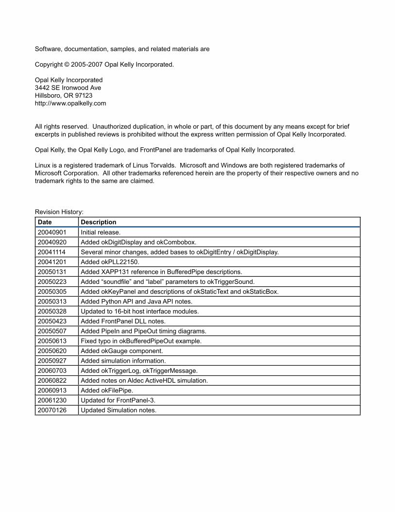
Software, documentation, samples, and related materials are
Copyright © 2005-2007 Opal Kelly Incorporated.
Opal Kelly Incorporated3442 SE Ironwood AveHillsboro, OR 97123http://www.opalkelly.com
All rights reserved. Unauthorized duplication, in whole or part, of this document by any means except for brief excerpts in published reviews is prohibited without the express written permission of Opal Kelly Incorporated.
Opal Kelly, the Opal Kelly Logo, and FrontPanel are trademarks of Opal Kelly Incorporated.
Linux is a registered trademark of Linus Torvalds. Microsoft and Windows are both registered trademarks of Microsoft Corporation. All other trademarks referenced herein are the property of their respective owners and no trademark rights to the same are claimed.
Revision History:Date Description20040901 Initial release.20040920 Added okDigitDisplay and okCombobox.20041114 Several minor changes, added bases to okDigitEntry / okDigitDisplay.20041201 Added okPLL22150.20050131 Added XAPP131 reference in BufferedPipe descriptions.20050223 Added “soundfile” and “label” parameters to okTriggerSound.20050305 Added okKeyPanel and descriptions of okStaticText and okStaticBox.20050313 Added Python API and Java API notes.20050328 Updated to 16-bit host interface modules.20050423 Added FrontPanel DLL notes.20050507 Added PipeIn and PipeOut timing diagrams.20050613 Fixed typo in okBufferedPipeOut example.20050620 Added okGauge component.20050927 Added simulation information.20060703 Added okTriggerLog, okTriggerMessage.20060822 Added notes on Aldec ActiveHDL simulation.20060913 Added okFilePipe.20061230 Updated for FrontPanel-3.20070126 Updated Simulation notes.
Contents
An Introduction to FrontPanel . . . . . . . . . . . . . . . . . . . . . . . . . . . . . . 7Terminology . . . . . . . . . . . . . . . . . . . . . . . . . . . . . . . . . . . . . . . . . . . . . . . . . . . . 7Basic Functionality . . . . . . . . . . . . . . . . . . . . . . . . . . . . . . . . . . . . . . . . . . . . . . 8
Peripheral Configuration . . . . . . . . . . . . . . . . . . . . . . . . . . . . . . . . . . . . . . . 8Flexibility Outside the Design . . . . . . . . . . . . . . . . . . . . . . . . . . . . . . . . . . . . . . 8
Controllability . . . . . . . . . . . . . . . . . . . . . . . . . . . . . . . . . . . . . . . . . . . . . . . 8Observability . . . . . . . . . . . . . . . . . . . . . . . . . . . . . . . . . . . . . . . . . . . . . . . . 9
XML and FrontPanel Components . . . . . . . . . . . . . . . . . . . . . . . . . . . . . . . . . . 9HDL Endpoints . . . . . . . . . . . . . . . . . . . . . . . . . . . . . . . . . . . . . . . . . . . . . . . . . 9
Designing with FrontPanel . . . . . . . . . . . . . . . . . . . . . . . . . . . . . . . . 11Endpoints . . . . . . . . . . . . . . . . . . . . . . . . . . . . . . . . . . . . . . . . . . . . . . . . . . . . . 11
Wires . . . . . . . . . . . . . . . . . . . . . . . . . . . . . . . . . . . . . . . . . . . . . . . . . . . . . 12Triggers . . . . . . . . . . . . . . . . . . . . . . . . . . . . . . . . . . . . . . . . . . . . . . . . . . . 13Pipes . . . . . . . . . . . . . . . . . . . . . . . . . . . . . . . . . . . . . . . . . . . . . . . . . . . . . . 13Block-Throttled Pipes . . . . . . . . . . . . . . . . . . . . . . . . . . . . . . . . . . . . . . . . . 14
Components . . . . . . . . . . . . . . . . . . . . . . . . . . . . . . . . . . . . . . . . . . . . . . . . . . . 14Performance Notes . . . . . . . . . . . . . . . . . . . . . . . . . . . . . . . . . . . . . . . . . . . . . . 14
Wires and Triggers . . . . . . . . . . . . . . . . . . . . . . . . . . . . . . . . . . . . . . . . . . . 14Pipes (Bulk Transfers) . . . . . . . . . . . . . . . . . . . . . . . . . . . . . . . . . . . . . . . . 15Block-Throttled Pipes (Bulk Transfers) . . . . . . . . . . . . . . . . . . . . . . . . . . . . 16Isochronous Transfers? . . . . . . . . . . . . . . . . . . . . . . . . . . . . . . . . . . . . . . . 16
Application Programmer’s Interface . . . . . . . . . . . . . . . . . . . . . . . . . 17Samples . . . . . . . . . . . . . . . . . . . . . . . . . . . . . . . . . . . . . . . . . . . . . . . . . . . 17
Organization . . . . . . . . . . . . . . . . . . . . . . . . . . . . . . . . . . . . . . . . . . . . . . . . . . . 18The okCUsbFrontPanel Class . . . . . . . . . . . . . . . . . . . . . . . . . . . . . . . . . . . . . 18
USB Device Interaction . . . . . . . . . . . . . . . . . . . . . . . . . . . . . . . . . . . . . . . 18Device Configuration . . . . . . . . . . . . . . . . . . . . . . . . . . . . . . . . . . . . . . . . . 19FPGA Communication . . . . . . . . . . . . . . . . . . . . . . . . . . . . . . . . . . . . . . . . 19
Communicating with Multiple Devices . . . . . . . . . . . . . . . . . . . . . . . . . . . . . . . 20Querying Attached Devices . . . . . . . . . . . . . . . . . . . . . . . . . . . . . . . . . . . . 20Connecting to a Specific Device . . . . . . . . . . . . . . . . . . . . . . . . . . . . . . . . . 20
API Communication . . . . . . . . . . . . . . . . . . . . . . . . . . . . . . . . . . . . . . . . . . . . . 21Wires . . . . . . . . . . . . . . . . . . . . . . . . . . . . . . . . . . . . . . . . . . . . . . . . . . . . . 21Triggers . . . . . . . . . . . . . . . . . . . . . . . . . . . . . . . . . . . . . . . . . . . . . . . . . . . 21Pipes . . . . . . . . . . . . . . . . . . . . . . . . . . . . . . . . . . . . . . . . . . . . . . . . . . . . . . 22Block-Throttled Pipes . . . . . . . . . . . . . . . . . . . . . . . . . . . . . . . . . . . . . . . . . 22
Example Usage . . . . . . . . . . . . . . . . . . . . . . . . . . . . . . . . . . . . . . . . . . . . . . . . . 22Regarding Device “Ownership” . . . . . . . . . . . . . . . . . . . . . . . . . . . . . . . . . . . . . 23Python API . . . . . . . . . . . . . . . . . . . . . . . . . . . . . . . . . . . . . . . . . . . . . . . . . . . . 23
Required Files . . . . . . . . . . . . . . . . . . . . . . . . . . . . . . . . . . . . . . . . . . . . . . 23Example Usage . . . . . . . . . . . . . . . . . . . . . . . . . . . . . . . . . . . . . . . . . . . . . 24
Java API . . . . . . . . . . . . . . . . . . . . . . . . . . . . . . . . . . . . . . . . . . . . . . . . . . . . . . 24Required Files . . . . . . . . . . . . . . . . . . . . . . . . . . . . . . . . . . . . . . . . . . . . . . 24Example Usage . . . . . . . . . . . . . . . . . . . . . . . . . . . . . . . . . . . . . . . . . . . . . 24
FrontPanel DLL . . . . . . . . . . . . . . . . . . . . . . . . . . . . . . . . . . . . . . . . . . . . . . . . . 25Example Usage (C) . . . . . . . . . . . . . . . . . . . . . . . . . . . . . . . . . . . . . . . . . . 26Example Usage (Matlab) . . . . . . . . . . . . . . . . . . . . . . . . . . . . . . . . . . . . . . 27
Matlab API . . . . . . . . . . . . . . . . . . . . . . . . . . . . . . . . . . . . . . . . . . . . . . . . . . . . . 28DLL Header File . . . . . . . . . . . . . . . . . . . . . . . . . . . . . . . . . . . . . . . . . . . . . 28Support Status . . . . . . . . . . . . . . . . . . . . . . . . . . . . . . . . . . . . . . . . . . . . . . 28
HDL Modules . . . . . . . . . . . . . . . . . . . . . . . . . . . . . . . . . . . . . . . . . . 29Building FPGA Projects with FrontPanel HDL Modules . . . . . . . . . . . . . . . . . . 29XEM3001v1 Note . . . . . . . . . . . . . . . . . . . . . . . . . . . . . . . . . . . . . . . . . . . . . . . 30FPGA Resource Requirements . . . . . . . . . . . . . . . . . . . . . . . . . . . . . . . . . . . . . 31The Host Interface . . . . . . . . . . . . . . . . . . . . . . . . . . . . . . . . . . . . . . . . . . . . . . 31
okHostInterface . . . . . . . . . . . . . . . . . . . . . . . . . . . . . . . . . . . . . . . . . . . . . 31Endpoint Types . . . . . . . . . . . . . . . . . . . . . . . . . . . . . . . . . . . . . . . . . . . . . . . . . 32
Endpoint Addresses . . . . . . . . . . . . . . . . . . . . . . . . . . . . . . . . . . . . . . . . . . 33okWireIn . . . . . . . . . . . . . . . . . . . . . . . . . . . . . . . . . . . . . . . . . . . . . . . . . . . 33okWireOut . . . . . . . . . . . . . . . . . . . . . . . . . . . . . . . . . . . . . . . . . . . . . . . . . . 33okTriggerIn . . . . . . . . . . . . . . . . . . . . . . . . . . . . . . . . . . . . . . . . . . . . . . . . . 34okTriggerOut . . . . . . . . . . . . . . . . . . . . . . . . . . . . . . . . . . . . . . . . . . . . . . . . 34okPipeIn . . . . . . . . . . . . . . . . . . . . . . . . . . . . . . . . . . . . . . . . . . . . . . . . . . . 34okPipeOut . . . . . . . . . . . . . . . . . . . . . . . . . . . . . . . . . . . . . . . . . . . . . . . . . . 35okBTPipeIn . . . . . . . . . . . . . . . . . . . . . . . . . . . . . . . . . . . . . . . . . . . . . . . . . 36okBTPipeOut . . . . . . . . . . . . . . . . . . . . . . . . . . . . . . . . . . . . . . . . . . . . . . . 37okBufferedPipeIn . . . . . . . . . . . . . . . . . . . . . . . . . . . . . . . . . . . . . . . . . . . . 38okBufferedPipeOut . . . . . . . . . . . . . . . . . . . . . . . . . . . . . . . . . . . . . . . . . . . 39
Using the FrontPanel Application . . . . . . . . . . . . . . . . . . . . . . . . . . . 41Selecting the Active Device . . . . . . . . . . . . . . . . . . . . . . . . . . . . . . . . . . . . . . . . 42
Device Identifier String . . . . . . . . . . . . . . . . . . . . . . . . . . . . . . . . . . . . . . . . 42FPGA Configuration Download . . . . . . . . . . . . . . . . . . . . . . . . . . . . . . . . . . . . . 42
Drag and Drop . . . . . . . . . . . . . . . . . . . . . . . . . . . . . . . . . . . . . . . . . . . . . . 42PLL Configuration (CY22150) . . . . . . . . . . . . . . . . . . . . . . . . . . . . . . . . . . . . . . 42
VCO Setup . . . . . . . . . . . . . . . . . . . . . . . . . . . . . . . . . . . . . . . . . . . . . . . . . 43Divider #1 and #2 . . . . . . . . . . . . . . . . . . . . . . . . . . . . . . . . . . . . . . . . . . . . 43Outputs . . . . . . . . . . . . . . . . . . . . . . . . . . . . . . . . . . . . . . . . . . . . . . . . . . . . 43EEPROM Read . . . . . . . . . . . . . . . . . . . . . . . . . . . . . . . . . . . . . . . . . . . . . 43EEPROM Write . . . . . . . . . . . . . . . . . . . . . . . . . . . . . . . . . . . . . . . . . . . . . . 44Apply . . . . . . . . . . . . . . . . . . . . . . . . . . . . . . . . . . . . . . . . . . . . . . . . . . . . . . 44Example PLL Configurations . . . . . . . . . . . . . . . . . . . . . . . . . . . . . . . . . . . 44
PLL Configuration (CY22393) . . . . . . . . . . . . . . . . . . . . . . . . . . . . . . . . . . . . . . 44Loading a FrontPanel Profile . . . . . . . . . . . . . . . . . . . . . . . . . . . . . . . . . . . . . . 45
Drag and Drop . . . . . . . . . . . . . . . . . . . . . . . . . . . . . . . . . . . . . . . . . . . . . . 45Preferences . . . . . . . . . . . . . . . . . . . . . . . . . . . . . . . . . . . . . . . . . . . . . . . . . . . . 45
Wire Update Rate . . . . . . . . . . . . . . . . . . . . . . . . . . . . . . . . . . . . . . . . . . . . 45Configure PLL Before FPGA Download . . . . . . . . . . . . . . . . . . . . . . . . . . . 45Show Panels in Taskbar . . . . . . . . . . . . . . . . . . . . . . . . . . . . . . . . . . . . . . . 46Enable Asynchronous Transfers . . . . . . . . . . . . . . . . . . . . . . . . . . . . . . . . . 46
Component XML . . . . . . . . . . . . . . . . . . . . . . . . . . . . . . . . . . . . . . . . 47XML . . . . . . . . . . . . . . . . . . . . . . . . . . . . . . . . . . . . . . . . . . . . . . . . . . . . . . . . . . 47
Basic Structure for FrontPanel . . . . . . . . . . . . . . . . . . . . . . . . . . . . . . . . . . 47Comments . . . . . . . . . . . . . . . . . . . . . . . . . . . . . . . . . . . . . . . . . . . . . . . . . 48Start-Tags and End-Tags . . . . . . . . . . . . . . . . . . . . . . . . . . . . . . . . . . . . . . 48Case Sensitivity . . . . . . . . . . . . . . . . . . . . . . . . . . . . . . . . . . . . . . . . . . . . . 48
Element Data Types . . . . . . . . . . . . . . . . . . . . . . . . . . . . . . . . . . . . . . . . . . . . . 49Component Types . . . . . . . . . . . . . . . . . . . . . . . . . . . . . . . . . . . . . . . . . . . . . . . 49
okStaticText . . . . . . . . . . . . . . . . . . . . . . . . . . . . . . . . . . . . . . . . . . . . . . . . 50okStaticBox . . . . . . . . . . . . . . . . . . . . . . . . . . . . . . . . . . . . . . . . . . . . . . . . . 50okPushbutton (Wire In) . . . . . . . . . . . . . . . . . . . . . . . . . . . . . . . . . . . . . . . . 50okToggleButton (Wire In) . . . . . . . . . . . . . . . . . . . . . . . . . . . . . . . . . . . . . . 51okToggleCheck (Wire In) . . . . . . . . . . . . . . . . . . . . . . . . . . . . . . . . . . . . . . 51okDigitEntry (Wire In) . . . . . . . . . . . . . . . . . . . . . . . . . . . . . . . . . . . . . . . . . 52okSlider (Wire In) . . . . . . . . . . . . . . . . . . . . . . . . . . . . . . . . . . . . . . . . . . . . 53okCombobox (Wire In) . . . . . . . . . . . . . . . . . . . . . . . . . . . . . . . . . . . . . . . . 53okLED (Wire Out) . . . . . . . . . . . . . . . . . . . . . . . . . . . . . . . . . . . . . . . . . . . . 54okHex (Wire Out) . . . . . . . . . . . . . . . . . . . . . . . . . . . . . . . . . . . . . . . . . . . . 54okDigitDisplay (Wire Out) . . . . . . . . . . . . . . . . . . . . . . . . . . . . . . . . . . . . . . 55okGauge (Wire Out) . . . . . . . . . . . . . . . . . . . . . . . . . . . . . . . . . . . . . . . . . . 56

okTriggerButton (Trigger In) . . . . . . . . . . . . . . . . . . . . . . . . . . . . . . . . . . . . 56okTriggerSound (Trigger Out) . . . . . . . . . . . . . . . . . . . . . . . . . . . . . . . . . . . 57okTriggerLog (Trigger Out) . . . . . . . . . . . . . . . . . . . . . . . . . . . . . . . . . . . . . 57okTriggerMessage (Trigger Out) . . . . . . . . . . . . . . . . . . . . . . . . . . . . . . . . 57okFilePipe (Pipe In, Pipe Out, Trigger In) . . . . . . . . . . . . . . . . . . . . . . . . . . 58okPLL22150 . . . . . . . . . . . . . . . . . . . . . . . . . . . . . . . . . . . . . . . . . . . . . . . . 59okPLL22393 . . . . . . . . . . . . . . . . . . . . . . . . . . . . . . . . . . . . . . . . . . . . . . . . 60okKeyPanel (Wire In, Trigger In) . . . . . . . . . . . . . . . . . . . . . . . . . . . . . . . . 61
FrontPanel Host Simulation . . . . . . . . . . . . . . . . . . . . . . . . . . . . . . . . 65System Simulation Model . . . . . . . . . . . . . . . . . . . . . . . . . . . . . . . . . . . . . . . . . 65Simulation Requirements . . . . . . . . . . . . . . . . . . . . . . . . . . . . . . . . . . . . . . . . . 66
Configuring ActiveHDL . . . . . . . . . . . . . . . . . . . . . . . . . . . . . . . . . . . . . . . . 66Configuring ModelSim . . . . . . . . . . . . . . . . . . . . . . . . . . . . . . . . . . . . . . . . 66
Adding Host Simulation to a Test Fixture . . . . . . . . . . . . . . . . . . . . . . . . . . . . . 67Example Test Fixtures . . . . . . . . . . . . . . . . . . . . . . . . . . . . . . . . . . . . . . . . 67Reset . . . . . . . . . . . . . . . . . . . . . . . . . . . . . . . . . . . . . . . . . . . . . . . . . . . . . 67Simulating Pipes . . . . . . . . . . . . . . . . . . . . . . . . . . . . . . . . . . . . . . . . . . . . . 67
Simulation in Aldec ActiveHDL . . . . . . . . . . . . . . . . . . . . . . . . . . . . . . . . . . . . . 68Design Workspace Setup . . . . . . . . . . . . . . . . . . . . . . . . . . . . . . . . . . . . . . 68
Example - First . . . . . . . . . . . . . . . . . . . . . . . . . . . . . . . . . . . . . . . . . . . . . . . . . 69Required Files . . . . . . . . . . . . . . . . . . . . . . . . . . . . . . . . . . . . . . . . . . . . . . 69Perform the Simulation . . . . . . . . . . . . . . . . . . . . . . . . . . . . . . . . . . . . . . . . 69Analyzing the Results . . . . . . . . . . . . . . . . . . . . . . . . . . . . . . . . . . . . . . . . . 70Simulation Accuracy . . . . . . . . . . . . . . . . . . . . . . . . . . . . . . . . . . . . . . . . . . 71
Example - DES Tester . . . . . . . . . . . . . . . . . . . . . . . . . . . . . . . . . . . . . . . . . . . . 71
Appendix A: A Simple Example . . . . . . . . . . . . . . . . . . . . . . . . . . . . . 73Toplevel Description . . . . . . . . . . . . . . . . . . . . . . . . . . . . . . . . . . . . . . . . . . . . . 74
Target Logic . . . . . . . . . . . . . . . . . . . . . . . . . . . . . . . . . . . . . . . . . . . . . . . . 74FrontPanel Interface Modules . . . . . . . . . . . . . . . . . . . . . . . . . . . . . . . . . . 75
FrontPanel XML Description . . . . . . . . . . . . . . . . . . . . . . . . . . . . . . . . . . . . . . . 75okPanel . . . . . . . . . . . . . . . . . . . . . . . . . . . . . . . . . . . . . . . . . . . . . . . . . . . . 75okToggleButton . . . . . . . . . . . . . . . . . . . . . . . . . . . . . . . . . . . . . . . . . . . . . . 76okLED . . . . . . . . . . . . . . . . . . . . . . . . . . . . . . . . . . . . . . . . . . . . . . . . . . . . . 76
Other Samples . . . . . . . . . . . . . . . . . . . . . . . . . . . . . . . . . . . . . . . . . . . . . . . . . 76
Appendix B: The Counters Sample . . . . . . . . . . . . . . . . . . . . . . . . . . 79Hardware Description . . . . . . . . . . . . . . . . . . . . . . . . . . . . . . . . . . . . . . . . . . . . 79
Counter #1 . . . . . . . . . . . . . . . . . . . . . . . . . . . . . . . . . . . . . . . . . . . . . . . . . 80Counter #2 . . . . . . . . . . . . . . . . . . . . . . . . . . . . . . . . . . . . . . . . . . . . . . . . . 80
Endpoints . . . . . . . . . . . . . . . . . . . . . . . . . . . . . . . . . . . . . . . . . . . . . . . . . . . . . 81Wire In (0x00) . . . . . . . . . . . . . . . . . . . . . . . . . . . . . . . . . . . . . . . . . . . . . . . 81Trigger In (0x40) . . . . . . . . . . . . . . . . . . . . . . . . . . . . . . . . . . . . . . . . . . . . . 81Wire Out (0x20, 0x21, and 0x22) . . . . . . . . . . . . . . . . . . . . . . . . . . . . . . . . 81
FrontPanel Components . . . . . . . . . . . . . . . . . . . . . . . . . . . . . . . . . . . . . . . . . . 82Panel 1: Counters Example . . . . . . . . . . . . . . . . . . . . . . . . . . . . . . . . . . . . 82Panel 2: Pushbuttons . . . . . . . . . . . . . . . . . . . . . . . . . . . . . . . . . . . . . . . . . 82
Quick Reference - Endpoints . . . . . . . . . . . . . . . . . . . . . . . . . . . . . . 83Quick Reference - Components . . . . . . . . . . . . . . . . . . . . . . . . . . . . 84

7
FrontPanel User’s Manual
www.opalkelly.com
An Introduction to FrontPanel
FrontPanel is a software platform designed to make using Opal Kelly FPGA experimenta-tion boards easier, more productive, more powerful, and more configurable. Most importantly, FrontPanel provides the basic functionality required to configure the hardware including the FPGA and peripherals on-board. After FPGA configuration, the USB interface switches from a high-speed download port to active communication with FrontPanel allowing you to interface and control your FPGA design from within a single application. By virtualizing many common controls found on typical evaluation (or prototyping) boards, FrontPanel enables far greater flexibility and capability than pure hardware-based approaches.
TerminologyCollectively, “FrontPanel” describes several components that make up the FrontPanel environ-ment:
• “FrontPanel HDL” - HDL modules you design into your FPGA hardware that makes your design “FrontPanel Enabled” and allows it to communicate with the PC.
• “FrontPanel Firmware” - Firmware running on the USB microcontroller that provides the conduit for FPGA/PC communication.
• “FrontPanel API” - A complete programmer’s interface allowing you to design custom PC applications that communicate with your FrontPanel Enabled hardware.
• “FrontPanel Application” - A flexible software application providing virtual instrumentation to your hardware such as LEDs, hex displays, numeric entry, pushbuttons, and so on.
8
FrontPanel User’s Manual
www.opalkelly.com
Basic FunctionalityFrontPanel is, most importantly, support software for Opal Kelly’s FPGA experimentation mod-ules. In that role, FrontPanel allows you to quickly and easily download FPGA configuration files via USB to a target device. Once the configuration file is downloaded, the device now takes on that design’s personality and is ready for use. If desired, FrontPanel’s role is now complete.
Peripheral ConfigurationOpal Kelly XEM devices contain additional peripherals to integrate FPGAs into your projects. PLLs, audio CODECs, Flash memory, and other peripherals can benefit from the simple, single-source configuration that FrontPanel offers. PLL outputs are independently configurable through easy-to-use setup dialogs. Flash memory can be programmed, cleared, and reprogrammed in a variety of ways and audio CODECs can be setup for different configurations.
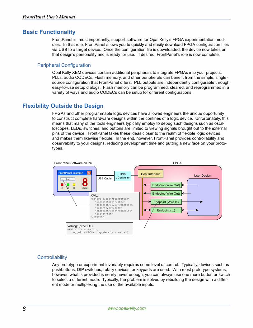
Flexibility Outside the DesignFPGAs and other programmable logic devices have allowed engineers the unique opportunity to construct complete hardware designs within the confines of a logic device. Unfortunately, this means that many of the tools engineers typically employ to debug such designs such as oscil-loscopes, LEDs, switches, and buttons are limited to viewing signals brought out to the external pins of the device. FrontPanel takes these ideas closer to the realm of flexible logic devices and makes them likewise flexible. In the end, however, FrontPanel provides controllability and observability to your designs, reducing development time and putting a new face on your proto-types.
FrontPanel Software on PC FPGA
User DesignUSBuController
Host Interface
Endpoint (Wire Out)
Endpoint (Wire In)
Endpoint (...)
Endpoint (Wire Out)
USB Cable
XML:<object class="pushbutton"> <label>Start</label> <position>10,10</position> <size>80,20</size> <endpoint>0x08</endpoint> <bit>3</bit></object>
Verilog: (or VHDL)okWireIn startEP(..., .ep_addr(8’h08), .ep_data(buttonwire));
ControllabilityAny prototype or experiment invariably requires some level of control. Typically, devices such as pushbuttons, DIP switches, rotary devices, or keypads are used. With most prototype systems, however, what is provided is nearly never enough; you can always use one more button or switch to select a different mode. Typically, the problem is solved by rebuilding the design with a differ-ent mode or multiplexing the use of the available inputs.
9
FrontPanel User’s Manual
www.opalkelly.com
FrontPanel offers another solution. With a simple change in a couple files, new virtual buttons and switches can be added quickly and connected to the proper points in your design.
ObservabilityPrototypes also require some level of observability, usually offered in the form of LEDs, hexa-decimal displays, and LCDs or sampled externally by oscilloscopes and logic analyzers. Again, however, there is the problem of limited resources in the typical prototype system. Only so many LEDs and displays are present on an I/O board, so the problem is remedied by adding more I/O boards or multiplexing the use of the current lot.
FrontPanel’s flexibility means you can display all sorts of information, in real-time, about the state of any number of signals in your design. It’s like having an I/O board that allows you to add and remove components at will without taking up valuable pins on the FPGA.
XML and FrontPanel ComponentsXML is the eXtensible Markup Language used in the latest generation of software applications and other forms of markup (such as XHTML). It is simply a way to describe data that can be ma-nipulated by any XML-supporting editor and in a platform-agnostic way. At its core, XML is just a text file containing tags which correspond to nodes of a tree. Each node can have properties and values.
FrontPanel interfaces are described using XML tags so they can be read and written with any standard text editor. This means that adding components to your virtual “I/O board” is as easy as adding a few lines to a text file. It also means that as FrontPanel grows in its capabilities, the interface descriptions will be forward (and backward) compatible. As additional functionality is added to FrontPanel, you will be able to take advantage of it by simply adding to your current projects.
HDL EndpointsOn the FPGA side of the interface, “Endpoints” are used to connect FrontPanel components to signals in your design. These endpoints work just like any external pin. You simply connect the signals you want to control or observe to the endpoint ports. Then, connect the endpoint mod-ules to a shared bus and place a Host Interface module on that same shared bus. The Host In-terface along with FrontPanel software and drivers take care of the rest. Signals within the FPGA are immediately visible within FrontPanel and FrontPanel can now control any input endpoints you’ve connected.
Additional endpoints can be added at any time simply by instantiating additional endpoint mod-ules. The modules are designed to consume very little FPGA resources so the effect on your design is minimal.

10
FrontPanel User’s Manual
www.opalkelly.com
11
FrontPanel User’s Manual
www.opalkelly.com
Designing with FrontPanel
FrontPanel’s main purpose is to move data between your PC and your FPGA in order to pro-vide a convenient and effective way for you to work with the design. FrontPanel was designed to interface simply and easily with new and existing FPGA designs in a way which is powerful enough to apply to a large number of interface methods, yet simple enough to apply to a design in minutes. More importantly, FrontPanel attempts to make the specific implementation of the physical interface (that is, the USB interface) disappear so that those details don’t get in the way of your work.
FrontPanel introduces the concept of “endpoints” to your FPGA design. An endpoint is a bundle of interconnect internal to your design that transports data to or from the PC in some fashion. In many cases, the endpoint can be created from an existing signal in your design which you want to observe in FrontPanel. In other cases, you will create an endpoint to perform a specific data transfer.
“Components” are the corresponding PC-side interface to an endpoint in the FPGA. Compo-nents may correspond to a single bit on an endpoint or to several endpoints. For example, an okTriggerButton activates a single bit on a Trigger In endpoint. In contrast, a field that allows you to enter or display a number spanning more than 256 would map to multiple endpoints.
EndpointsIn FrontPanel, an endpoint is either a Wire, Trigger, or Pipe, and is either directed in or out of your design. By way of definition, the endpoint will always be labelled from the perspective of the device (FPGA) so an “In” endpoint moves data into the design while an “Out” endpoint moves data out of the design. All of the endpoints in a design are instantiated from Opal Kelly modules and share a common connection to the Host Interface which provides the connection to the PC through the USB interface on the XEM board.
12
FrontPanel User’s Manual
www.opalkelly.com
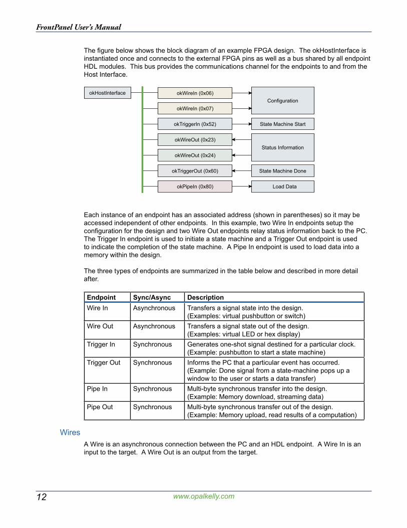
The figure below shows the block diagram of an example FPGA design. The okHostInterface is instantiated once and connects to the external FPGA pins as well as a bus shared by all endpoint HDL modules. This bus provides the communications channel for the endpoints to and from the Host Interface.
okHostInterface
okWireIn (0x07)
okWireOut (0x24)
okTriggerOut (0x60)
okTriggerIn (0x52)
okWireIn (0x06)
okWireOut (0x23)
okPipeIn (0x80)
Status Information
Configuration
State Machine Start
State Machine Done
Load Data
Each instance of an endpoint has an associated address (shown in parentheses) so it may be accessed independent of other endpoints. In this example, two Wire In endpoints setup the configuration for the design and two Wire Out endpoints relay status information back to the PC. The Trigger In endpoint is used to initiate a state machine and a Trigger Out endpoint is used to indicate the completion of the state machine. A Pipe In endpoint is used to load data into a memory within the design.
The three types of endpoints are summarized in the table below and described in more detail after.
Endpoint Sync/Async DescriptionWire In Asynchronous Transfers a signal state into the design.
(Examples: virtual pushbutton or switch)Wire Out Asynchronous Transfers a signal state out of the design.
(Examples: virtual LED or hex display)Trigger In Synchronous Generates one-shot signal destined for a particular clock.
(Example: pushbutton to start a state machine)Trigger Out Synchronous Informs the PC that a particular event has occurred.
(Example: Done signal from a state-machine pops up a window to the user or starts a data transfer)
Pipe In Synchronous Multi-byte synchronous transfer into the design.(Example: Memory download, streaming data)
Pipe Out Synchronous Multi-byte synchronous transfer out of the design.(Example: Memory upload, read results of a computation)
WiresA Wire is an asynchronous connection between the PC and an HDL endpoint. A Wire In is an input to the target. A Wire Out is an output from the target.

13
FrontPanel User’s Manual
www.opalkelly.com
Wires are designed to fill the position of devices such as LEDs, hexadecimal displays, pushbut-tons, DIP switches, and so on. These devices are not synchronous to the design and they usu-ally convey the current state of some internal signal (in the case of Wire Outs).
Wires are updated periodically using a polling mechanism. The rate of update is determined by how fast the PC can poll the FPGA. In FrontPanel, this value is user-configurable. Even at the highest update rate (25 millisecond period), very little USB bandwidth is consumed, so you should not notice any performance penalty.
Because some FrontPanel components may convey the state of several wires, and in order to avoid multiple transfers over the USB, all wires are captured and updated simultaneously. That is not to say they are synchronous, but that they are all updated at the same time. Therefore, all 64 Wire Ins (or Wire Outs) are transferred together.
TriggersTriggers are synchronous connections between the PC and an HDL endpoint. A Trigger In is an input to the target. A Trigger Out is an output from the target. Triggers are used to initiate or signal a single event such as the start or end of a state machine.
As an input to the HDL, a Trigger In creates a signal that is asserted for a single clock cycle. The synchronization clock is determined by the user and the HDL module takes care of crossing the clock domains properly.
As an output from the HDL, a Trigger Out triggers the PC when a signal’s rising edge is detected. The “rising edge” is actually determined by the signal’s state from one clock cycle to the next and does not detect glitches. It should be noted that because FrontPanel polls the FPGA periodically, it can only detect independent trigger outs between polls. That is, once a Trigger Out is “set,” it remains set until the next poll clears it.
PipesPipes are synchronous connections between FrontPanel and an HDL endpoint. Unlike Triggers which convey a single event, however, Pipes are designed to transmit a series of bytes to (or from) the endpoint. They are most commonly used to download or upload memory contents but may also be used to stream data to or from the device.
From the HDL point-of-view, a Pipe is always a master. That is, the PC (and therefore the HDL module that implements the Pipe) controls the transaction for both Pipe Ins and Pipe Outs. In addition, the Pipe transactions must be performed at the endpoint’s clock rate (48 MHz). To suc-cessfully cross this clock boundary, a buffered (FIFO) arrangement is suggested. (okBuffered-Pipes provide built-in asynchronous FIFOs)
Although access to the Pipe is always from a slave point of view, use of Triggers provides an ef-fective negotiation method to synchronize the transfer of blocks of data.
Pipe transfer rates will vary depending on host hardware. Our tests indicate transfer rates to the FPGA are around 39 MB/s and transfer rates from the FPGA are about 39 MB/s. For more detail, see Performance Notes below.
FrontPanel-3 NoteFirmware supporting FrontPanel 1.4.1 and earlier was limited to approximately 32MB/s to the FPGA and 19 MB/s from the FPGA.
14
FrontPanel User’s Manual
www.opalkelly.com
Block-Throttled PipesBlock-Throttled Pipes (or BTPipes) are very similar to “standard” Pipes with one important distinc-tion: BTPipes provide a way for the FPGA to “throttle” transfer through the pipe at a block level. The block size is programmable from 1 to 512 words (2 to 1024 bytes). The FPGA throttles data through the BTPipe by asserting or deasserting a READY signal to the USB microcontroller. This allows the FPGA to halt data transfer until data is available or ready to be processed.
BTPipes provide the same transfer rates as standard pipes, but the throttling allows them to be used in a wider array of applications and can, generally, increase performance by reducing the overhead that would otherwise be required to negotiate the transfer at a higher level.
FrontPanel-3 NoteBTPipes are only available using firmware supporting FrontPanel-3.
Full-Speed USB NoteOn full-speed USB busses, the block size is limited to 1 to 32 words (2 to 64 bytes).
ComponentsComponents represent the other half of the interface, each connecting to an appropriate endpoint or multiple endpoints within the design. Most components have a graphical representation within FrontPanel such as a pushbutton, virtual LED, or numerical display. Some components, howev-er, are hidden from view. An example of a hidden component would be one that makes a sound in response to a Trigger Out.
Performance NotesOpal Kelly’s FrontPanel consists of HDL modules within the FPGA, firmware on the USB microcontroller, and an API on the PC that have been optimized for both performance and a clean abstraction. Our latest FrontPanel-3 release has improved performance significantly while offering several features that customers have requested.
Achieving the highest level of performance for your particular application requires an understand-ing of the components being used and how certain things affect performance. By following a few simple strategies and applying these notes, your application will be a top USB performer and still benefit from the ease of use and flexible abstraction that only FrontPanel provides.
Measured PerformanceMeasured performance figures in this section were taken on an Athlon 64 X2 4800+ machine running Windows XP SP2. USB performance can vary significantly depending on a number of factors including the motherboard make and model, specific driver versions installed, and ma-chine load.
Wires and TriggersWires and triggers provide the most basic form of communication between the FPGA and the PC. From a performance perspective, wires can be read or written several hundred times per second. All WireIns are read simultaneously, regardless of which ones you are interested in. Similarly, all WireOuts are written simultaneously.
15
FrontPanel User’s Manual
www.opalkelly.com
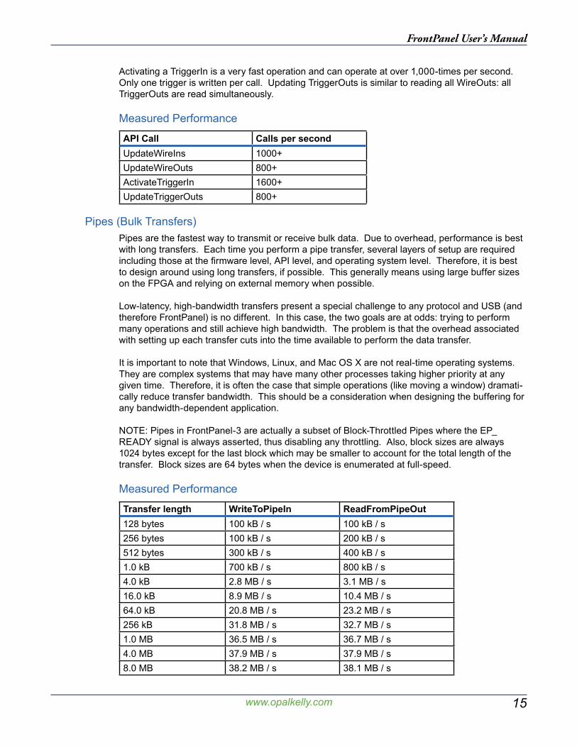
Activating a TriggerIn is a very fast operation and can operate at over 1,000-times per second. Only one trigger is written per call. Updating TriggerOuts is similar to reading all WireOuts: all TriggerOuts are read simultaneously.
Measured Performance
API Call Calls per secondUpdateWireIns 1000+UpdateWireOuts 800+ActivateTriggerIn 1600+UpdateTriggerOuts 800+
Pipes (Bulk Transfers)Pipes are the fastest way to transmit or receive bulk data. Due to overhead, performance is best with long transfers. Each time you perform a pipe transfer, several layers of setup are required including those at the firmware level, API level, and operating system level. Therefore, it is best to design around using long transfers, if possible. This generally means using large buffer sizes on the FPGA and relying on external memory when possible.
Low-latency, high-bandwidth transfers present a special challenge to any protocol and USB (and therefore FrontPanel) is no different. In this case, the two goals are at odds: trying to perform many operations and still achieve high bandwidth. The problem is that the overhead associated with setting up each transfer cuts into the time available to perform the data transfer.
It is important to note that Windows, Linux, and Mac OS X are not real-time operating systems. They are complex systems that may have many other processes taking higher priority at any given time. Therefore, it is often the case that simple operations (like moving a window) dramati-cally reduce transfer bandwidth. This should be a consideration when designing the buffering for any bandwidth-dependent application.
NOTE: Pipes in FrontPanel-3 are actually a subset of Block-Throttled Pipes where the EP_READY signal is always asserted, thus disabling any throttling. Also, block sizes are always 1024 bytes except for the last block which may be smaller to account for the total length of the transfer. Block sizes are 64 bytes when the device is enumerated at full-speed.
Measured Performance
Transfer length WriteToPipeIn ReadFromPipeOut128 bytes 100 kB / s 100 kB / s256 bytes 100 kB / s 200 kB / s512 bytes 300 kB / s 400 kB / s1.0 kB 700 kB / s 800 kB / s4.0 kB 2.8 MB / s 3.1 MB / s16.0 kB 8.9 MB / s 10.4 MB / s64.0 kB 20.8 MB / s 23.2 MB / s256 kB 31.8 MB / s 32.7 MB / s1.0 MB 36.5 MB / s 36.7 MB / s4.0 MB 37.9 MB / s 37.9 MB / s8.0 MB 38.2 MB / s 38.1 MB / s
16
FrontPanel User’s Manual
www.opalkelly.com
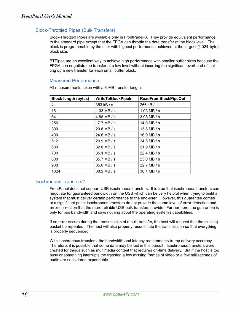
Block-Throttled Pipes (Bulk Transfers)Block-Throttled Pipes are available only in FrontPanel-3. They provide equivalent performance to the standard pipe except that the FPGA can throttle the data transfer at the block level. The block is programmable by the user with highest performance achieved at the largest (1,024-byte) block size.
BTPipes are an excellent way to achieve high performance with smaller buffer sizes because the FPGA can negotiate the transfer at a low level without incurring the significant overhead of set-ting up a new transfer for each small buffer block.
Measured PerformanceAll measurements taken with a 8-MB transfer length.
Block length (bytes) WriteToBlockPipeIn ReadFromBlockPipeOut4 353 kB / s 266 kB / s16 1.33 MB / s 1.03 MB / s64 4.88 MB / s 3.98 MB / s256 17.7 MB / s 14.0 MB / s300 20.6 MB / s 13.8 MB / s400 24.8 MB / s 16.9 MB / s512 29.9 MB / s 24.5 MB / s600 32.8 MB / s 21.9 MB / s700 35.1 MB / s 22.4 MB / s800 35.7 MB / s 23.0 MB / s900 35.0 MB / s 22.7 MB / s1024 38.2 MB / s 38.1 MB / s
Isochronous Transfers?FrontPanel does not support USB isochronous transfers. It is true that isochronous transfers can negotiate for guaranteed bandwidth on the USB which can be very helpful when trying to build a system that must deliver certain performance to the end-user. However, this guarantee comes at a significant price: isochronous transfers do not provide the same level of error-detection and error-correction that the more reliable USB bulk transfers provide. Furthermore, the guarantee is only for bus bandwidth and says nothing about the operating system’s capabilities.
If an error occurs during the transmission of a bulk transfer, the host will request that the missing packet be repeated. The host will also properly reconstitute the transmission so that everything is properly sequenced.
With isochronous transfers, the bandwidth and latency requirements trump delivery accuracy. Therefore, it is possible that some data may be lost in this pursuit. Isochronous transfers were created for things such as multimedia content that requires on-time delivery. But if the host is too busy or something interrupts the transfer, a few missing frames of video or a few milliseconds of audio are considered expendable.
17
FrontPanel User’s Manual
www.opalkelly.com
The FrontPanel application provides a turnkey method to make basic user interaction available to your FPGA hardware but it is not suitable for all applications, particularly those which require further data processing on the PC side of the interface or when data transfer between the PC and FPGA is required. In these cases, a custom software application is usually a better fit. To this end, Opal Kelly provides the FrontPanel Application Programmer’s Interface (API), a cross-platform interface to the underlying USB driver layer.
The FrontPanel API contains methods which communicate via the USB to the microcontroller on the XEM, but the methods have been specifically designed to interface with FPGA hardware in a manner which is consistent with most hardware designs. The API provides methods to interface directly with the FrontPanel HDL modules such as wires, triggers, and pipes. Because of this abstraction, some flexibility in the USB interface is sacrificed for a dramatically reduced develop-ment cycle (and learning curve!) for connecting your FPGA hardware to your custom software.
The library is written in C++ and is provided as a dynamically-linked ibrary. However, Python and Java versions of the API are also available and can make FPGA development even faster. A de-tailed API reference is available in HTML format (or Compiled HTML under Windows). Because the Python and Java APIs are generated automatically from the C++ API, most of the methods are identical and you can use the same API reference for all languages. This section of the manual provides a higher-level introduction to the API’s organization and use.
SamplesOften, the best way to learn how to apply a programming interface is to see examples of its ap-plication. Please see the samples included with FrontPanel for these examples.
Application Programmer’s Interface
18
FrontPanel User’s Manual
www.opalkelly.com
OrganizationThe FrontPanel API is provided as a dynamically-linked library that you include with your applica-tion. The interface to the DLL is C, but a C++ wrapper is provided to make the entire DLL appear as if it were a native C++ class in your application.
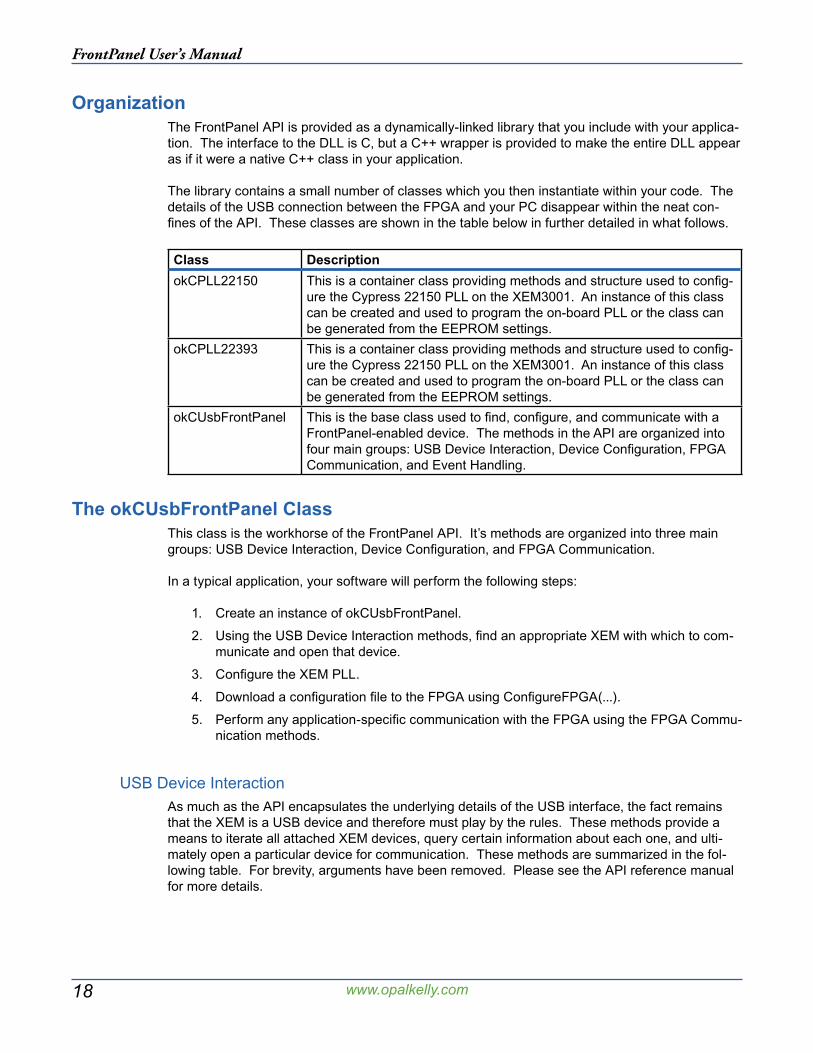
The library contains a small number of classes which you then instantiate within your code. The details of the USB connection between the FPGA and your PC disappear within the neat con-fines of the API. These classes are shown in the table below in further detailed in what follows.
Class DescriptionokCPLL22150 This is a container class providing methods and structure used to config-
ure the Cypress 22150 PLL on the XEM3001. An instance of this class can be created and used to program the on-board PLL or the class can be generated from the EEPROM settings.
okCPLL22393 This is a container class providing methods and structure used to config-ure the Cypress 22150 PLL on the XEM3001. An instance of this class can be created and used to program the on-board PLL or the class can be generated from the EEPROM settings.
okCUsbFrontPanel This is the base class used to find, configure, and communicate with a FrontPanel-enabled device. The methods in the API are organized into four main groups: USB Device Interaction, Device Configuration, FPGA Communication, and Event Handling.
The okCUsbFrontPanel ClassThis class is the workhorse of the FrontPanel API. It’s methods are organized into three main groups: USB Device Interaction, Device Configuration, and FPGA Communication.
In a typical application, your software will perform the following steps:
1. Create an instance of okCUsbFrontPanel.
2. Using the USB Device Interaction methods, find an appropriate XEM with which to com-municate and open that device.
3. Configure the XEM PLL.
4. Download a configuration file to the FPGA using ConfigureFPGA(...).
5. Perform any application-specific communication with the FPGA using the FPGA Commu-nication methods.
USB Device InteractionAs much as the API encapsulates the underlying details of the USB interface, the fact remains that the XEM is a USB device and therefore must play by the rules. These methods provide a means to iterate all attached XEM devices, query certain information about each one, and ulti-mately open a particular device for communication. These methods are summarized in the fol-lowing table. For brevity, arguments have been removed. Please see the API reference manual for more details.
19
FrontPanel User’s Manual
www.opalkelly.com
Method DescriptionGetDeviceCount Returns the number of FrontPanel devices attached to the PC.
Note that this counts -all- FrontPanel devices and also queries information about each device which can be retrieved using the Get-DeviceListXXX methods below.
GetDeviceListModel Retrieves the board model of a connected device.GetDeviceListSerial Retrieves the serial number of a connected devicce.OpenBySerial Opens a device (with matching serial number) for communication.GetDeviceMinorVersion Retrieves the current firmware minor version.GetDeviceMajorVersion Retrieves the current firmware major version.GetSerialNumber Returns a 10-digit serial number unique to each device. This serial
number may be used to select a specific device on the USB bus. The serial number is set at the factory and is not user-modifiable.
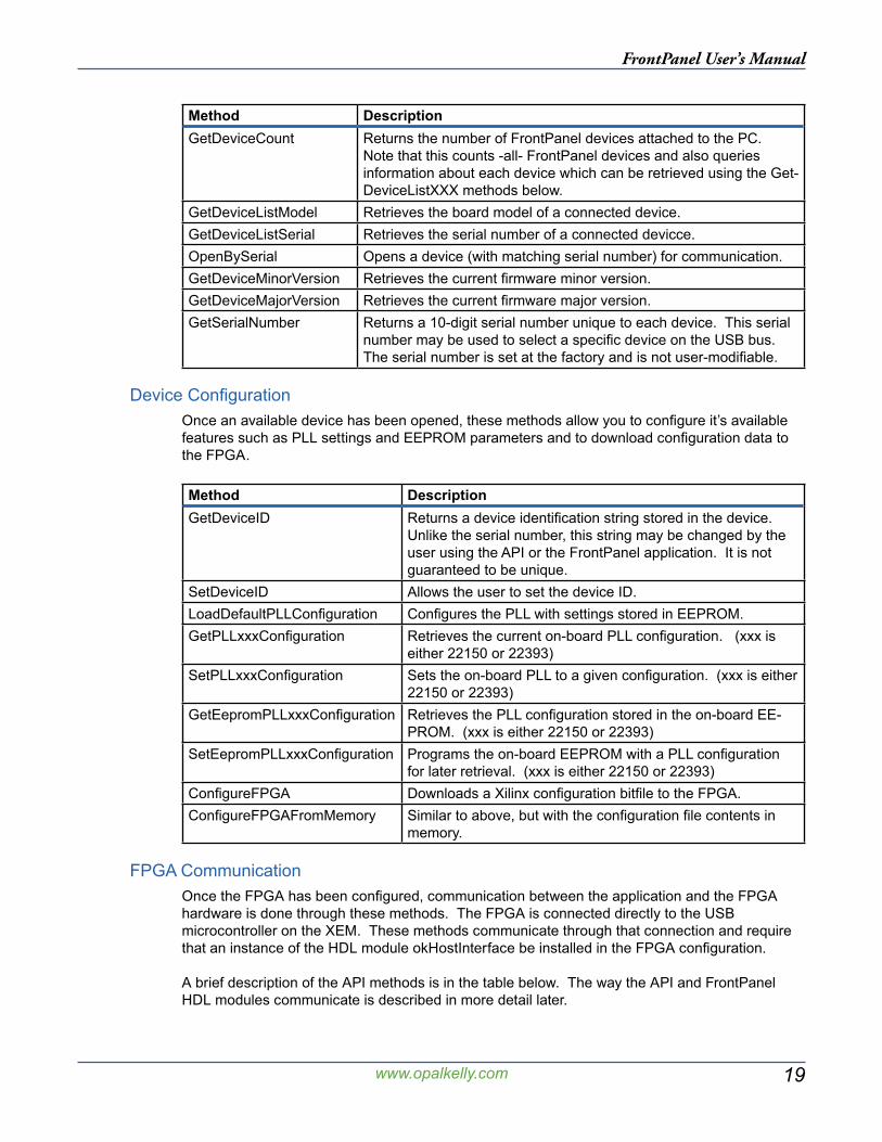
Device ConfigurationOnce an available device has been opened, these methods allow you to configure it’s available features such as PLL settings and EEPROM parameters and to download configuration data to the FPGA.
Method DescriptionGetDeviceID Returns a device identification string stored in the device.
Unlike the serial number, this string may be changed by the user using the API or the FrontPanel application. It is not guaranteed to be unique.
SetDeviceID Allows the user to set the device ID.LoadDefaultPLLConfiguration Configures the PLL with settings stored in EEPROM.GetPLLxxxConfiguration Retrieves the current on-board PLL configuration. (xxx is
either 22150 or 22393)SetPLLxxxConfiguration Sets the on-board PLL to a given configuration. (xxx is either
22150 or 22393)GetEepromPLLxxxConfiguration Retrieves the PLL configuration stored in the on-board EE-
PROM. (xxx is either 22150 or 22393)SetEepromPLLxxxConfiguration Programs the on-board EEPROM with a PLL configuration
for later retrieval. (xxx is either 22150 or 22393)ConfigureFPGA Downloads a Xilinx configuration bitfile to the FPGA.ConfigureFPGAFromMemory Similar to above, but with the configuration file contents in
memory.
FPGA CommunicationOnce the FPGA has been configured, communication between the application and the FPGA hardware is done through these methods. The FPGA is connected directly to the USB microcontroller on the XEM. These methods communicate through that connection and require that an instance of the HDL module okHostInterface be installed in the FPGA configuration.
A brief description of the API methods is in the table below. The way the API and FrontPanel HDL modules communicate is described in more detail later.
20
FrontPanel User’s Manual
www.opalkelly.com
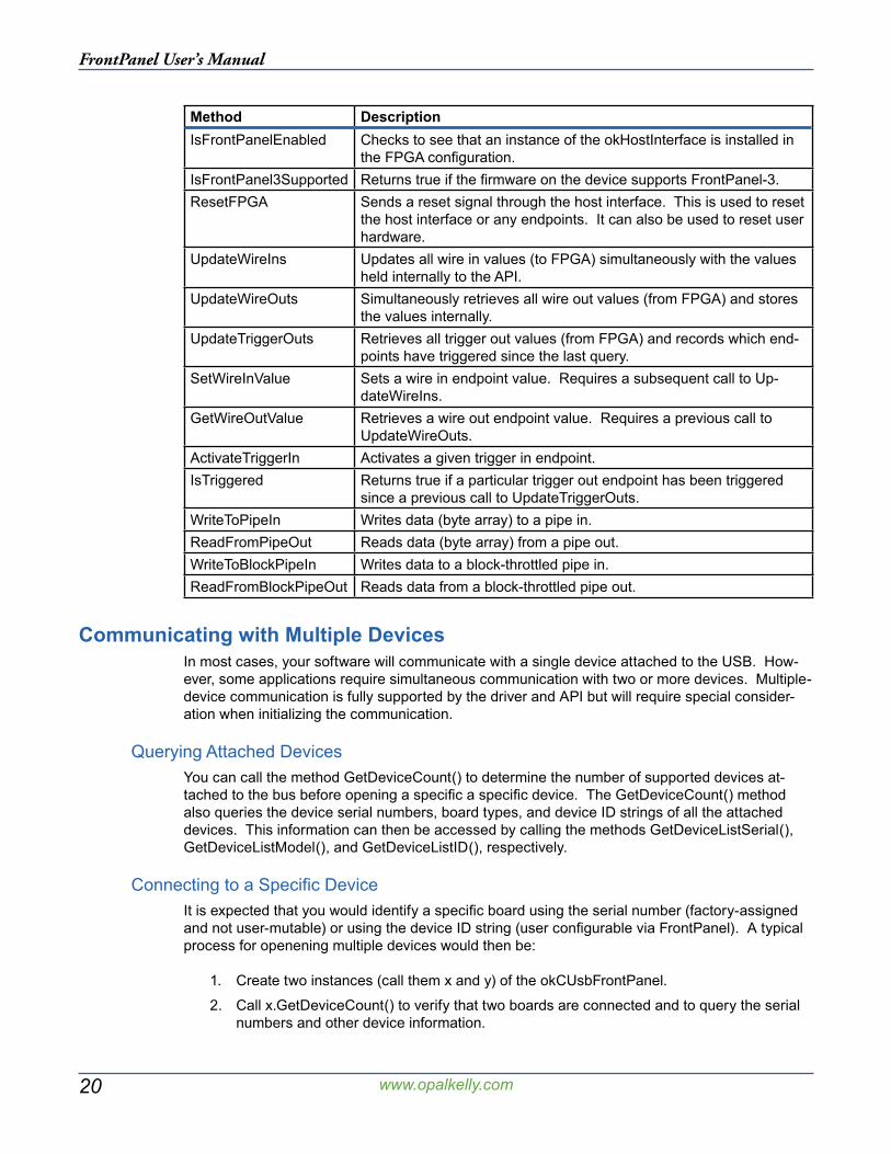
Method DescriptionIsFrontPanelEnabled Checks to see that an instance of the okHostInterface is installed in
the FPGA configuration.IsFrontPanel3Supported Returns true if the firmware on the device supports FrontPanel-3.ResetFPGA Sends a reset signal through the host interface. This is used to reset
the host interface or any endpoints. It can also be used to reset user hardware.
UpdateWireIns Updates all wire in values (to FPGA) simultaneously with the values held internally to the API.
UpdateWireOuts Simultaneously retrieves all wire out values (from FPGA) and stores the values internally.
UpdateTriggerOuts Retrieves all trigger out values (from FPGA) and records which end-points have triggered since the last query.
SetWireInValue Sets a wire in endpoint value. Requires a subsequent call to Up-dateWireIns.
GetWireOutValue Retrieves a wire out endpoint value. Requires a previous call to UpdateWireOuts.
ActivateTriggerIn Activates a given trigger in endpoint.IsTriggered Returns true if a particular trigger out endpoint has been triggered
since a previous call to UpdateTriggerOuts.WriteToPipeIn Writes data (byte array) to a pipe in.ReadFromPipeOut Reads data (byte array) from a pipe out.WriteToBlockPipeIn Writes data to a block-throttled pipe in.ReadFromBlockPipeOut Reads data from a block-throttled pipe out.
Communicating with Multiple DevicesIn most cases, your software will communicate with a single device attached to the USB. How-ever, some applications require simultaneous communication with two or more devices. Multiple-device communication is fully supported by the driver and API but will require special consider-ation when initializing the communication.
Querying Attached DevicesYou can call the method GetDeviceCount() to determine the number of supported devices at-tached to the bus before opening a specific a specific device. The GetDeviceCount() method also queries the device serial numbers, board types, and device ID strings of all the attached devices. This information can then be accessed by calling the methods GetDeviceListSerial(), GetDeviceListModel(), and GetDeviceListID(), respectively.
Connecting to a Specific DeviceIt is expected that you would identify a specific board using the serial number (factory-assigned and not user-mutable) or using the device ID string (user configurable via FrontPanel). A typical process for openening multiple devices would then be:
1. Create two instances (call them x and y) of the okCUsbFrontPanel.
2. Call x.GetDeviceCount() to verify that two boards are connected and to query the serial numbers and other device information.
21
FrontPanel User’s Manual
www.opalkelly.com
3. Call serX = x.GetDeviceListSerial(0) to get the first device’s serial number.
4. Call serY = x.GetDeviceListSerial(1) to get the second device’s serial number.
5. Call x.OpenBySerial(serX) to open the first device.
6. Call y.OpenBySerial(serY) to open the second device.
Using this procedure, you would then have two instances which point to the two devices in your system. They have also been clearly associated with the specific hardware you specified, so there is no ambiguity.
API CommunicationThe three endpoint types (Wire, Trigger, Pipe) provide a means by which the PC and FPGA communicate. Each type is suited to a specific type of data transfer and has its own associated usage and rules.
WiresRecall that a wire is used to communicate asynchronous signal state between the host (PC) and the target (FPGA). The okHostInterface supports up to 32 Wire In endpoints and 32 Wire Out endpoints connected to it. To save bandwidth, all Wire In or Wire Out endpoints are updated at the same time and written or read by the host in one block.
All Wire In (to FPGA) endpoints are updated by the host at the same time with the call Up-dateWireIns(). Prior to this call, the application sets new Wire In values using the API method SetWireInValue(). The SetWireInValue() simply updates the wire values in a data structure inter-nal to the API. UpdateWireIns() then transfers these values to the FPGA.
All Wire Out (from FPGA) endpoints are likewise read by the host at the same time with a call to UpdateWireOuts(). This call reads all 32 Wire Out endpoints and stores their values in an inter-nal data structure. The specific endpoint values can then be read out using GetWireOutValue().
Note: UpdateWireIns() and UpdateWireOuts() also latch all wire endpoint data at the same time. Therefore, the data available on Wire Out endpoints are all captured synchronously (with the tar-get interface clock). Similarly, the data availble to Wire In endpoints is all latched synchronously with the target interface clock.
TriggersTriggers are used to communicate a singular event between the host and target. A Trigger In provides a way for the host to convey a “one-shot” on an arbitrary FPGA clock. A Trigger Out provides a way for the FPGA to signal the host with a “one-shot” or other single-event indicator.
Triggers are read and updated in a manner similar to Wires. All Trigger Ins are transferred to the FPGA at the same time and all Trigger Outs are transferred from the FPGA at the same time. However, due to common usage differences, Trigger Ins are not transferred immediately with the call to ActivateTriggerIn().
Trigger Out information is read from the FPGA using the call UpdateTriggerOuts(). Subsequent calls to IsTriggered() then return ‘true’ if the trigger has been activated since the last call to Upda-teTriggerOuts().
22
FrontPanel User’s Manual
www.opalkelly.com
PipesPipe communication is the synchronous communication of one or more bytes of data. In both Pipe In and Pipe Out cases, the host is the master. Therefore, the FPGA must be able to accept (or provide) data on any time. Wires, Triggers, and Buffered Pipes can make things a little more negotiable.
When data is written by the host to a Pipe In endpoint using WriteToPipeIn(...), the USB driver will packetize the data as necessary for the USB protocol. Once the transfer has started, it will continue to completion, so the FPGA must be prepared to accept all of the data.
When data is read by the host from a Pipe Out endpoint using ReadFromPipeOut(...), the USB driver will again packetize the data as necessary. The transfer will proceed from start to comple-tion, so the FPGA must be prepared to provide data to the Pipe Out as requested.
Byte OrderPipe data is transferred over the USB in 8-bit words but transferred to the FPGA in 16-bit words. Therefore, on the FPGA side (HDL), the Pipe interface has a 16-bit word width but on the PC side (API), the Pipe interface has an 8-bit word width.
When writing to Pipe Ins, the first byte written is transferred over the lower order bits of the data bus (7:0). The second byte written is transferred over the higher order bits of the data bus (15:8). Similarly, when reading from Pipe Outs, the lower order bits are the first byte read and the higher order bits are the second byte read.
Block-Throttled PipesBlock-Throttled Pipe communication is identical to Pipe communication with the additional speci-fication of a block size. The FPGA sends (or receives) data in blocks sized 2, 4, 6, ..., 1024 as specified by the arguments to the call. Block sizes are restricted to 64 bytes or less when using the device at full-speed.
Because the FPGA has the opportunity to stall the transfer by deasserting EP_READY, the call may fail with a timeout.
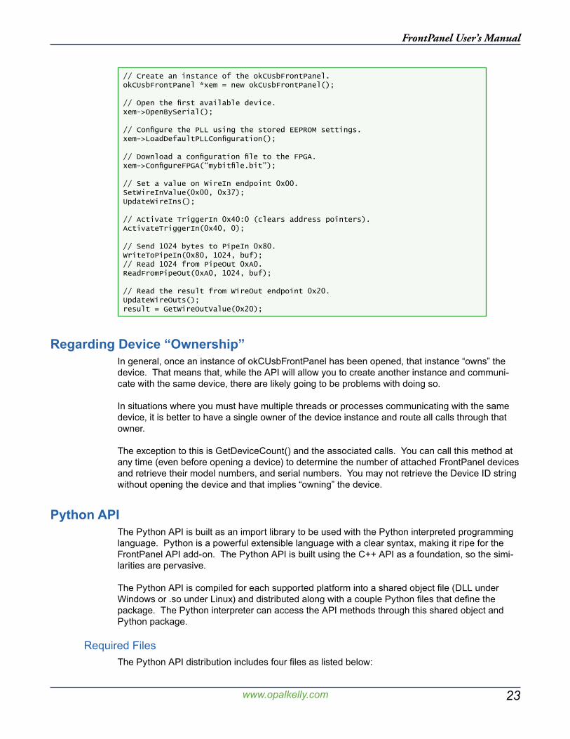
Example UsageBelow is a short code snippet that illustrates how the API might be used in a C++ application. More useful and detailed examples can be found in the Samples folder of the FrontPanel instal-lation.
23
FrontPanel User’s Manual
www.opalkelly.com
// Create an instance of the okCUsbFrontPanel.okCUsbFrontPanel *xem = new okCUsbFrontPanel();
// Open the first available device.xem->OpenBySerial();
// Configure the PLL using the stored EEPROM settings.xem->LoadDefaultPLLConfiguration();
// Download a configuration file to the FPGA.xem->ConfigureFPGA(“mybitfile.bit”);
// Set a value on WireIn endpoint 0x00.SetWireInValue(0x00, 0x37);UpdateWireIns();
// Activate TriggerIn 0x40:0 (clears address pointers).ActivateTriggerIn(0x40, 0);
// Send 1024 bytes to PipeIn 0x80.WriteToPipeIn(0x80, 1024, buf);// Read 1024 from PipeOut 0xA0.ReadFromPipeOut(0xA0, 1024, buf);
// Read the result from WireOut endpoint 0x20.UpdateWireOuts();result = GetWireOutValue(0x20);
Regarding Device “Ownership”In general, once an instance of okCUsbFrontPanel has been opened, that instance “owns” the device. That means that, while the API will allow you to create another instance and communi-cate with the same device, there are likely going to be problems with doing so.
In situations where you must have multiple threads or processes communicating with the same device, it is better to have a single owner of the device instance and route all calls through that owner.
The exception to this is GetDeviceCount() and the associated calls. You can call this method at any time (even before opening a device) to determine the number of attached FrontPanel devices and retrieve their model numbers, and serial numbers. You may not retrieve the Device ID string without opening the device and that implies “owning” the device.
Python APIThe Python API is built as an import library to be used with the Python interpreted programming language. Python is a powerful extensible language with a clear syntax, making it ripe for the FrontPanel API add-on. The Python API is built using the C++ API as a foundation, so the simi-larities are pervasive.
The Python API is compiled for each supported platform into a shared object file (DLL under Windows or .so under Linux) and distributed along with a couple Python files that define the package. The Python interpreter can access the API methods through this shared object and Python package.
Required FilesThe Python API distribution includes four files as listed below:
24
FrontPanel User’s Manual
www.opalkelly.com
● __init__.py
● __version__.py
● ok.py
● _ok.dll (Windows)
● _ok.so (Linux, Mac OS X)
These four files need to be in the current working directory where Python is started. Alterna-tively, they may be added to the Python site-packages directory within your Python distribution. Refer to the Python manual to see how this is done.
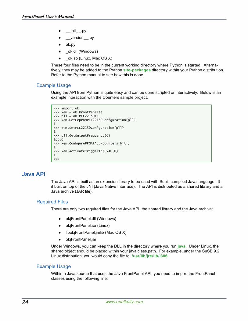
Example UsageUsing the API from Python is quite easy and can be done scripted or interactively. Below is an example interaction with the Counters sample project.
>>> import ok>>> xem = ok.FrontPanel()>>> pll = ok.PLL22150()>>> xem.GetEepromPLL22150Configuration(pll)1>>> xem.SetPLL22150Configuration(pll)1>>> pll.GetOutputFrequency(0)100.0>>> xem.ConfigureFPGA(‘c:\counters.bit’)1>>> xem.ActivateTriggerIn(0x40,0)1>>>
Java APIThe Java API is built as an extension library to be used with Sun’s compiled Java language. It it built on top of the JNI (Java Native Interface). The API is distributed as a shared library and a Java archive (JAR file).
Required FilesThere are only two required files for the Java API: the shared library and the Java archive:
● okjFrontPanel.dll (Windows)
● okjFrontPanel.so (Linux)
● libokjFrontPanel.jnilib (Mac OS X)
● okjFrontPanel.jar
Under Windows, you can keep the DLL in the directory where you run java. Under Linux, the shared object should be placed within your java.class.path. For example, under the SuSE 9.2 Linux distribution, you would copy the file to: /usr/lib/jre/lib/i386.
Example UsageWithin a Java source that uses the Java FrontPanel API, you need to import the FrontPanel classes using the following line:
25
FrontPanel User’s Manual
www.opalkelly.com
import com.opalkelly.frontpanel.*;
To actually load the FrontPanel library into Java, you will also need to make the following System call before using any FrontPanel API objects:
System.loadLibrary(“okjFrontPanel”);
Compiling a Java application for use with the Java API can be done on the command line using javac with the -classpath argument to specify the Java API JAR as shown below.
javac -classpath okjFrontPanel.jar MyClass.java
Likewise, when running the application, you need to add the Java API JAR to the classpath:
java -classpath .;okjFrontPanel.jar MyClass
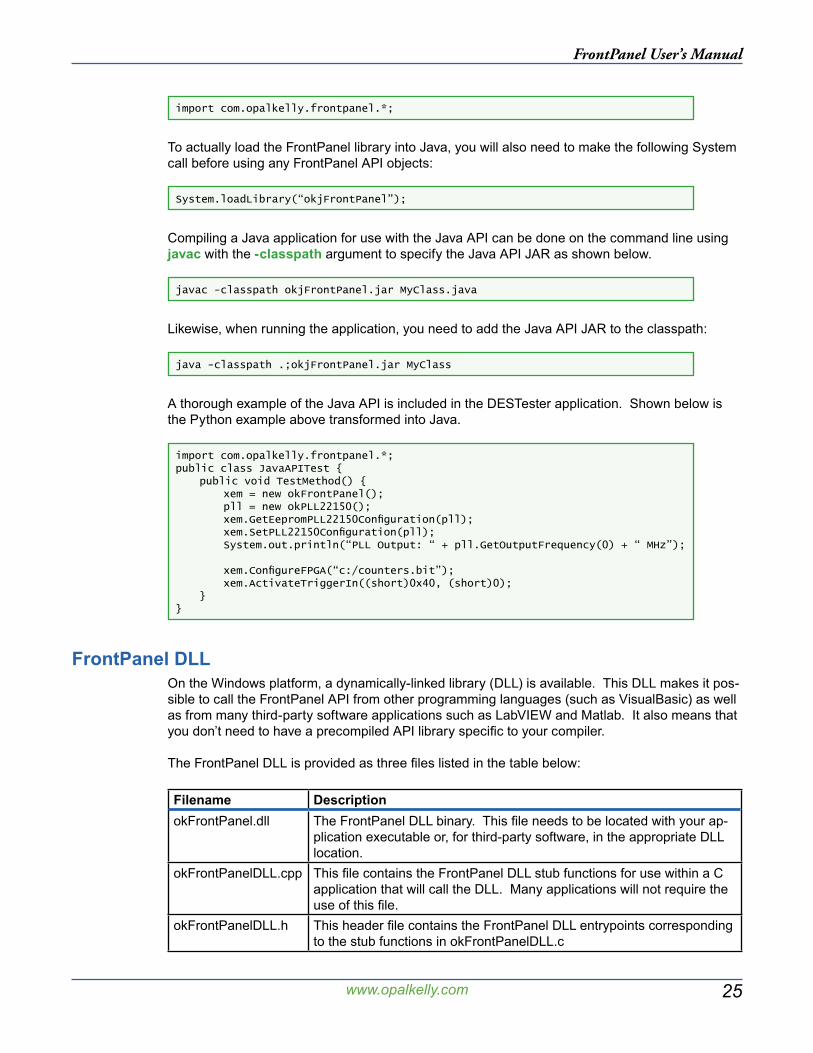
A thorough example of the Java API is included in the DESTester application. Shown below is the Python example above transformed into Java.
import com.opalkelly.frontpanel.*;public class JavaAPITest { public void TestMethod() { xem = new okFrontPanel(); pll = new okPLL22150(); xem.GetEepromPLL22150Configuration(pll); xem.SetPLL22150Configuration(pll); System.out.println(“PLL Output: “ + pll.GetOutputFrequency(0) + “ MHz”);
xem.ConfigureFPGA(“c:/counters.bit”); xem.ActivateTriggerIn((short)0x40, (short)0); }}
FrontPanel DLLOn the Windows platform, a dynamically-linked library (DLL) is available. This DLL makes it pos-sible to call the FrontPanel API from other programming languages (such as VisualBasic) as well as from many third-party software applications such as LabVIEW and Matlab. It also means that you don’t need to have a precompiled API library specific to your compiler.
The FrontPanel DLL is provided as three files listed in the table below:
Filename DescriptionokFrontPanel.dll The FrontPanel DLL binary. This file needs to be located with your ap-
plication executable or, for third-party software, in the appropriate DLL location.
okFrontPanelDLL.cpp This file contains the FrontPanel DLL stub functions for use within a C application that will call the DLL. Many applications will not require the use of this file.
okFrontPanelDLL.h This header file contains the FrontPanel DLL entrypoints corresponding to the stub functions in okFrontPanelDLL.c
26
FrontPanel User’s Manual
www.opalkelly.com
In most cases, each class method has a corresponding DLL entrypoint. This makes it easy to re-fer to the standard API documentation for calling information. One notable difference is that most DLL entrypoints require a pointer argument. This pointer is actually the pointer to the allocated C++ class object. Note, however, that this object is allocated and deallocated using DLL entry-points and therefore the DLL does NOT require C++ and can be used in any C application.
Example Usage (C)When using the DLL in a compiled C application, you will need to compile and link the okFrontPanelDLL.cpp file with your application. This file provides the stub functions that will load and call the DLL from your application. You will also need to include the file okFrontPanelDLL.h in each source file that calls the DLL.
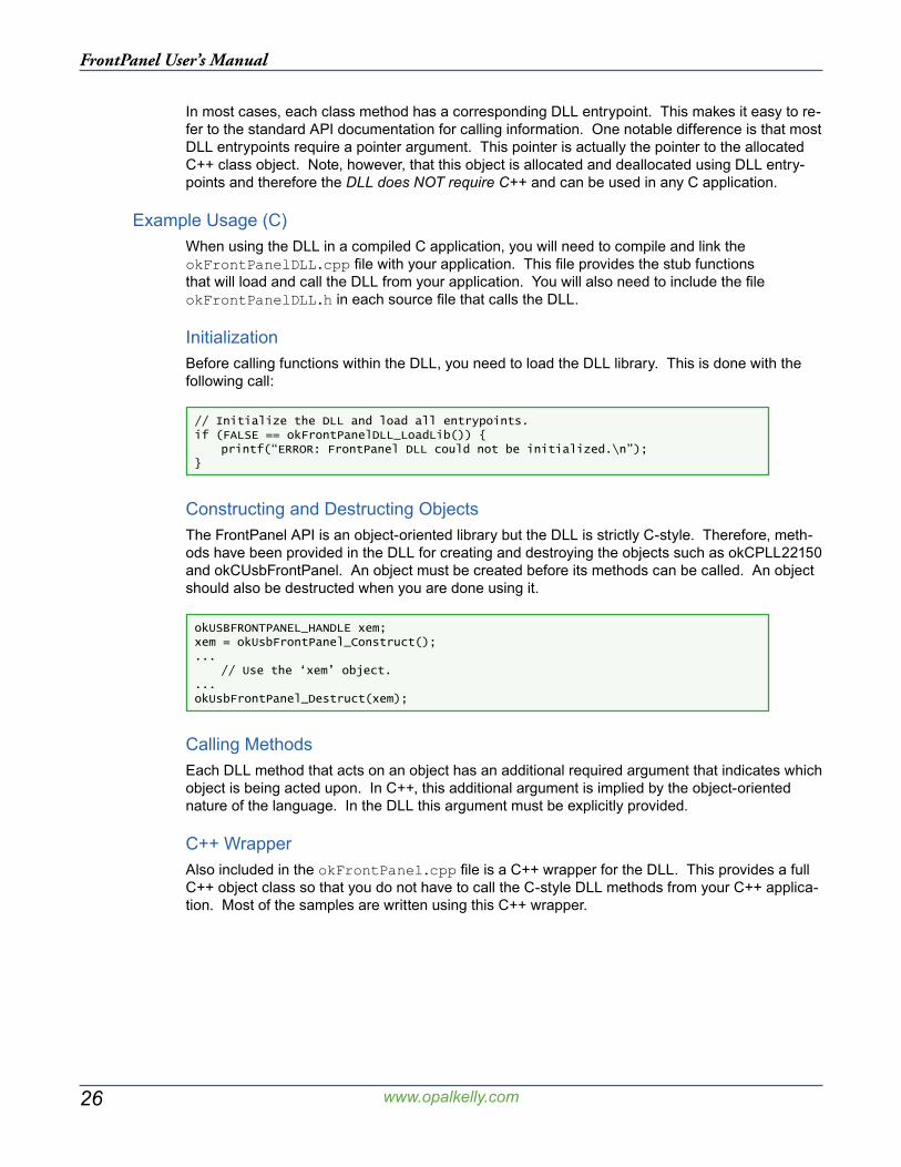
InitializationBefore calling functions within the DLL, you need to load the DLL library. This is done with the following call:
// Initialize the DLL and load all entrypoints.if (FALSE == okFrontPanelDLL_LoadLib()) { printf(“ERROR: FrontPanel DLL could not be initialized.\n”);}
Constructing and Destructing ObjectsThe FrontPanel API is an object-oriented library but the DLL is strictly C-style. Therefore, meth-ods have been provided in the DLL for creating and destroying the objects such as okCPLL22150 and okCUsbFrontPanel. An object must be created before its methods can be called. An object should also be destructed when you are done using it.
okUSBFRONTPANEL_HANDLE xem;xem = okUsbFrontPanel_Construct();... // Use the ‘xem’ object....okUsbFrontPanel_Destruct(xem);
Calling MethodsEach DLL method that acts on an object has an additional required argument that indicates which object is being acted upon. In C++, this additional argument is implied by the object-oriented nature of the language. In the DLL this argument must be explicitly provided.
C++ WrapperAlso included in the okFrontPanel.cpp file is a C++ wrapper for the DLL. This provides a full C++ object class so that you do not have to call the C-style DLL methods from your C++ applica-tion. Most of the samples are written using this C++ wrapper.
27
FrontPanel User’s Manual
www.opalkelly.com
okUSBFRONTPANEL_HANDLE xem;okPLL22150_HANDLE pll;
// Construct XEM and PLL objects.xem = okUsbFrontPanel_Construct();pll = okPLL22150_Construct();
// Setup the PLL.okPLL22150_SetVCOParameters(pll, 400, 48);okPLL22150_SetDiv1(pll, DivSrc_VCO, 8);okPLL22150_SetOutputSource(pll, 0, ClkSrc_Div1ByN);okPLL22150_SetOutputEnable(pll, 0, true);
// Configure the XEM PLL.okUsbFrontPanel_OpenBySerial(xem, NULL);okUsbFrontPanel_SetPLLConfiguration(xem, pll);
// Finished with the PLL.okPLL22150_Destruct(pll);
... // Use the ‘xem’ object....
okUsbFrontPanel_Destruct(xem);
Example Usage (Matlab)Matlab provides a convenient way to extend its own capabilities by calling user-provided DLL functions. This is done using a few native Matlab calls: loadlibrary, calllib, libisloaded, libfunc-tions, libfunctionsview.
For example, to load the FrontPanel DLL into Matlab for use, the following syntax can be used:
if ~libisloaded(‘okFrontPanel’) loadlibrary(‘okFrontPanel’, ‘okFrontPanelDLL.h’);end
You can view the calling conventions and conversions Matlab has applied to the DLL methods by calling the command “libfunctionsview(‘okFrontPanel’)”. An example way to call the DLL:
% Create a device structure:xid.ptr = 0;xid.serial = ‘‘;xid.deviceID = ‘‘;xid.major = 0;xid.minor = 0;
% Construct an XEM3001v2 and open the first device:xid.ptr = calllib(‘okFrontPanel’, ‘okUsbXEM3001v2_Construct’);[ret, x] = calllib(‘okFrontPanel’, ‘okUsbFrontPanel_Open’, xid.ptr, 0);[xid.major, x] = calllib(‘okFrontPanel’, ... ‘okUsbFrontPanel_GetDeviceMajorVersion’, xid.ptr);[xid.minor, x] = calllib(‘okFrontPanel’, ... ‘okUsbFrontPanel_GetDeviceMinorVersion’, xid.ptr);[x, xid.serial] = calllib(‘okFrontPanel’, ... ‘okUsbFrontPanel_GetSerialNumber’, xid.ptr, ‘ ‘);[x, xid.deviceID] = calllib(‘okFrontPanel’, ... ‘okUsbFrontPanel_GetDeviceID’, xid.ptr, ‘ ‘);
28
FrontPanel User’s Manual
www.opalkelly.com
Matlab APIWhile the above example shows how to use the FrontPanel DLL from within Matlab, we have al-ready provided a more thorough version of this API for your usage. It is provided as a fully-func-tioning sample of the DLL usage from within Matlab and utilizes Matlab’s object-oriented structure to provide an API that is very similar to the C++ API in usage.
DLL Header FileDue to a bug in Matlab’s DLL usage, a slightly modified DLL header file must be used when accessing the API through Matlab. This revised header defines the HANDLE objects as unsigned long rather than void *. If the revised header file is not used, memory leaks will occur in Matlab.
Support StatusPlease note that the Matlab API is not officially supported by Opal Kelly. While it is not officially supported, we would like to keep it up-to-date. Please contact us via email if you have any sug-gested changes to the Matlab API.

29
FrontPanel User’s Manual
www.opalkelly.com
HDL Modules
The use of FrontPanel components to control and observe pieces of your FPGA design requires the instantiation of one or more modules in your toplevel HDL. These modules can quickly and easily be added into an existing or new design and take care of all the dirty work of communicat-ing with the FrontPanel software.
The host interface is the block which connects directly to pins on the FPGA which are connected on the XEM board to the USB microcontroller. This is the entry point for FrontPanel into your design.
The endpoints connect to a shared control bus on the host interface. This internal bus is used to shuttle the endpoint connections to and from the host interface. Several endpoints may be connected to this shared bus. FrontPanel uses endpoint addresses to select which endpoint it is communicating with, so each endpoint must have its own unique address to work properly.
Building FPGA Projects with FrontPanel HDL ModulesThe FrontPanel HDL Modules are provided as pre-synthesized files which get included in your design flow. The following table lists these files and describes it’s content. By default, these files are installed at C:\Program Files\Opal Kelly\FrontPanel\FrontPanelHDL. In this directory are several subdirectories that contain HDL modules built for different Xilinx ISE versions. If you are using an XEM3001v1 (8-bit) board, choose a ‘v1’ directory. Otherwise, choose a ‘v2’ directory.
30
FrontPanel User’s Manual
www.opalkelly.com
Filename DescriptionokLibrary.v Verilog file containing black-box modules for Verilog projects.okLibrary.vhd VHDL file containing black-box modules for VHDL projects.okHostInterfaceCore.ngc Pre-synthesized Xilinx module for the Host Interface.okWireIn.ngc Pre-synthesized Xilinx module for the Wire In endpoint.okWireOut.ngc Pre-synthesized Xilinx module for the Wire Out endpoint.okTriggerIn.ngc Pre-synthesized Xilinx module for the Trigger In endpoint.okTriggerOut.ngc Pre-synthesized Xilinx module for the Trigger Out endpoint.okPipeIn.ngc Pre-synthesized Xilinx module for the Pipe In endpoint.okPipeOut.ngc Pre-synthesized Xilinx module for the Pipe Out endpoint.okBTPipeIn.ngc Pre-synthesized Xilinx module for the Block-Throttled Pipe In
endpoint.okBTPipeOut.ngc Pre-synthesized Xilinx module for the Block-Throttled Pipe
Out endpoint.
The Host Interface is actually broken into two components - a core component which is pre-synthesized and a wrapper component (in okLibrary.v or okLibrary.vhd) which includes the core component as well as IOBs required for the connections to FPGA pins.
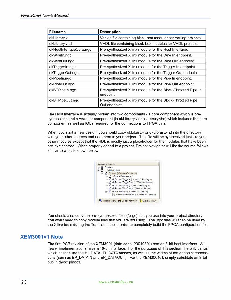
When you start a new design, you should copy okLibary.v or okLibrary.vhd into the directory with your other sources and add them to your project. This file will be synthesized just like your other modules except that the HDL is mostly just a placeholder for the modules that have been pre-synthesized. When properly added to a project, Project Navigator will list the source follows similar to what is shown below:
You should also copy the pre-synthesized files (*.ngc) that you use into your project directory. You won’t need to copy module files that you are not using. The .ngc files will then be used by the Xilinx tools during the Translate step in order to completely build the FPGA configuration file.
XEM3001v1 NoteThe first PCB revision of the XEM3001 (date code: 20040301) had an 8-bit host interface. All newer implementations have a 16-bit interface. For the purposes of this section, the only things which change are the HI_DATA, TI_DATA busses, as well as the widths of the endpoint connec-tions (such as EP_DATAIN and EP_DATAOUT). For the XEM3001v1, simply substitute an 8-bit bus in those places.
31
FrontPanel User’s Manual
www.opalkelly.com
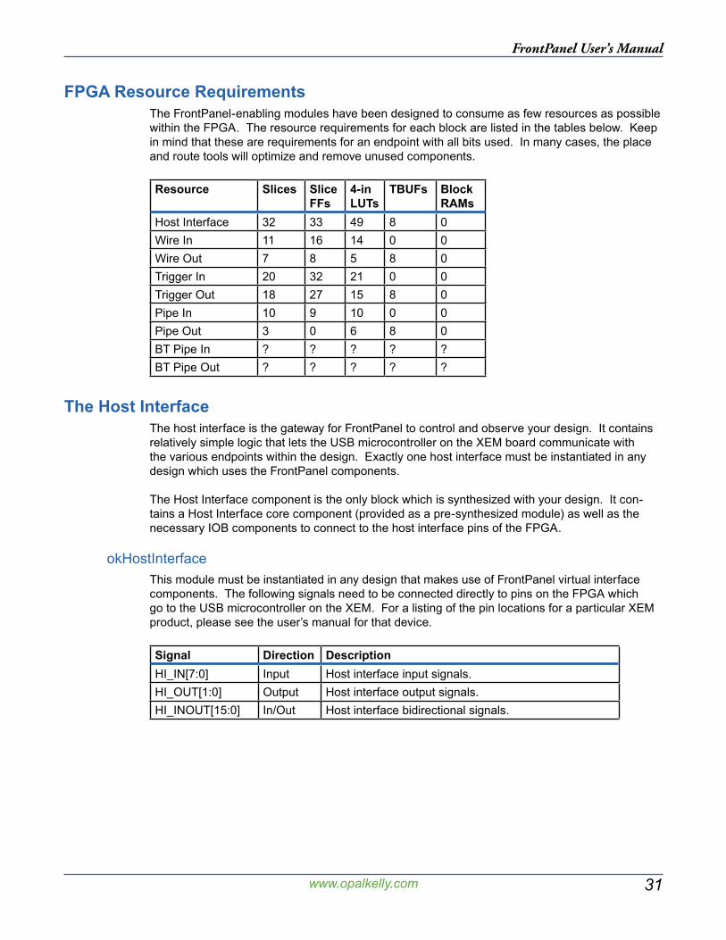
FPGA Resource RequirementsThe FrontPanel-enabling modules have been designed to consume as few resources as possible within the FPGA. The resource requirements for each block are listed in the tables below. Keep in mind that these are requirements for an endpoint with all bits used. In many cases, the place and route tools will optimize and remove unused components.
Resource Slices Slice FFs
4-in LUTs
TBUFs Block RAMs
Host Interface 32 33 49 8 0Wire In 11 16 14 0 0Wire Out 7 8 5 8 0Trigger In 20 32 21 0 0Trigger Out 18 27 15 8 0Pipe In 10 9 10 0 0Pipe Out 3 0 6 8 0BT Pipe In ? ? ? ? ?BT Pipe Out ? ? ? ? ?
The Host InterfaceThe host interface is the gateway for FrontPanel to control and observe your design. It contains relatively simple logic that lets the USB microcontroller on the XEM board communicate with the various endpoints within the design. Exactly one host interface must be instantiated in any design which uses the FrontPanel components.
The Host Interface component is the only block which is synthesized with your design. It con-tains a Host Interface core component (provided as a pre-synthesized module) as well as the necessary IOB components to connect to the host interface pins of the FPGA.
okHostInterfaceThis module must be instantiated in any design that makes use of FrontPanel virtual interface components. The following signals need to be connected directly to pins on the FPGA which go to the USB microcontroller on the XEM. For a listing of the pin locations for a particular XEM product, please see the user’s manual for that device.
Signal Direction DescriptionHI_IN[7:0] Input Host interface input signals.HI_OUT[1:0] Output Host interface output signals.HI_INOUT[15:0] In/Out Host interface bidirectional signals.
32
FrontPanel User’s Manual
www.opalkelly.com
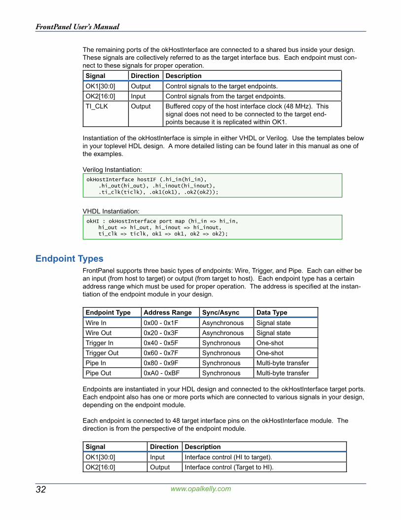
The remaining ports of the okHostInterface are connected to a shared bus inside your design. These signals are collectively referred to as the target interface bus. Each endpoint must con-nect to these signals for proper operation.Signal Direction DescriptionOK1[30:0] Output Control signals to the target endpoints.OK2[16:0] Input Control signals from the target endpoints.TI_CLK Output Buffered copy of the host interface clock (48 MHz). This
signal does not need to be connected to the target end-points because it is replicated within OK1.
Instantiation of the okHostInterface is simple in either VHDL or Verilog. Use the templates below in your toplevel HDL design. A more detailed listing can be found later in this manual as one of the examples.
Verilog Instantiation:okHostInterface hostIF (.hi_in(hi_in), .hi_out(hi_out), .hi_inout(hi_inout), .ti_clk(ticlk), .ok1(ok1), .ok2(ok2));
VHDL Instantiation:okHI : okHostInterface port map (hi_in => hi_in, hi_out => hi_out, hi_inout => hi_inout, ti_clk => ticlk, ok1 => ok1, ok2 => ok2);
Endpoint TypesFrontPanel supports three basic types of endpoints: Wire, Trigger, and Pipe. Each can either be an input (from host to target) or output (from target to host). Each endpoint type has a certain address range which must be used for proper operation. The address is specified at the instan-tiation of the endpoint module in your design.
Endpoint Type Address Range Sync/Async Data TypeWire In 0x00 - 0x1F Asynchronous Signal stateWire Out 0x20 - 0x3F Asynchronous Signal stateTrigger In 0x40 - 0x5F Synchronous One-shotTrigger Out 0x60 - 0x7F Synchronous One-shotPipe In 0x80 - 0x9F Synchronous Multi-byte transferPipe Out 0xA0 - 0xBF Synchronous Multi-byte transfer
Endpoints are instantiated in your HDL design and connected to the okHostInterface target ports. Each endpoint also has one or more ports which are connected to various signals in your design, depending on the endpoint module.
Each endpoint is connected to 48 target interface pins on the okHostInterface module. The direction is from the perspective of the endpoint module.
Signal Direction DescriptionOK1[30:0] Input Interface control (HI to target).OK2[16:0] Output Interface control (Target to HI).
33
FrontPanel User’s Manual
www.opalkelly.com
These signals are present in every endpoint. In the signal tables for the independent endpoints below, we have left out these common signals.
Endpoint AddressesEndpoints attach to the host interface on a shared bus. To properly route signals between the host (PC) and target endpoints, each endpoint must be assigned a unique 8-bit address. For performance reasons (to minimize USB transactions), each endpoint type has been assigned an address range as indicated in the table above. When assigning addresses to your endpoints, be sure to follow these ranges.
The endpoint address is assigned in HDL through an additional 8-bit input port on the endpoint instance. Example instantiation for each endpoint type are shown in the sections below.
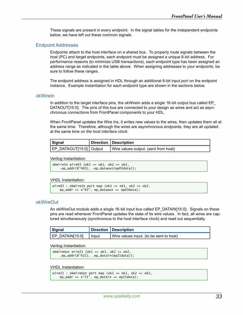
okWireInIn addition to the target interface pins, the okWireIn adds a single 16-bit output bus called EP_DATAOUT[15:0]. The pins of this bus are connected to your design as wires and act as asyn-chronous connections from FrontPanel components to your HDL.
When FrontPanel updates the Wire Ins, it writes new values to the wires, then updates them all at the same time. Therefore, although the wires are asynchronous endpoints, they are all updated at the same time on the host interface clock.
Signal Direction DescriptionEP_DATAOUT[15:0] Output Wire values output. (sent from host)
Verilog Instantiation:okWireIn wire03 (ok1 => ok1, ok2 => ok2, .ep_addr(8’h03), .ep_dataout(ep03data));
VHDL Instantiation:wire03 : okWireIn port map (ok1 => ok1, ok2 => ok2, ep_addr => x“03”, ep_dataout => ep03data);
okWireOutAn okWireOut module adds a single 16-bit input bus called EP_DATAIN[15:0]. Signals on these pins are read whenever FrontPanel updates the state of its wire values. In fact, all wires are cap-tured simultaneously (synchronous to the host interface clock) and read out sequentially.
Signal Direction DescriptionEP_DATAIN[15:0] Input Wire values input. (to be sent to host)
Verilog Instantiation:okWireOut wire21 (ok1 => ok1, ok2 => ok2, .ep_addr(8’h21), .ep_datain(ep21data));
VHDL Instantiation:wire21 : okWireOut port map (ok1 => ok1, ok2 => ok2, ep_addr => x“21”, ep_datain => ep21data);
34
FrontPanel User’s Manual
www.opalkelly.com
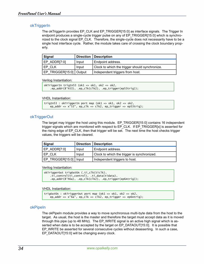
okTriggerInThe okTriggerIn provides EP_CLK and EP_TRIGGER[15:0] as interface signals. The Trigger In endpoint produces a single-cycle trigger pulse on any of EP_TRIGGER[15:0] which is synchro-nized to the clock signal EP_CLK. Therefore, the single-cycle does not necessarily have to be a single host interface cycle. Rather, the module takes care of crossing the clock boundary prop-erly.
Signal Direction DescriptionEP_ADDR[7:0] Input Endpoint address.EP_CLK Input Clock to which the trigger should synchronize.EP_TRIGGER[15:0] Output Independent triggers from host.
Verilog Instantiation:okTriggerIn trigIn53 (ok1 => ok1, ok2 => ok2, .ep_addr(8’h53), .ep_clk(clk2), .ep_trigger(ep53trig));
VHDL Instantiation:trigIn53 : okTriggerIn port map (ok1 => ok1, ok2 => ok2, ep_addr => x”53”, ep_clk => clk2, ep_trigger => ep53trig);
okTriggerOutThe target may trigger the host using this module. EP_TRIGGER[15:0] contains 16 independent trigger signals which are monitored with respect to EP_CLK. If EP_TRIGGER[x] is asserted for the rising edge of EP_CLK, then that trigger will be set. The next time the host checks trigger values, the triggers will be cleared.
Signal Direction DescriptionEP_ADDR[7:0] Input Endpoint address.EP_CLK Input Clock to which the trigger is synchronized.EP_TRIGGER[15:0] Input Independent triggers to host.
Verilog Instantiation:okTriggerOut trigOut6A (.ti_clk(ticlk), .ti_control(ti_control), .ti_data(tidata), .ep_addr(8’h6a), .ep_clk(clk2), .ep_trigger(ep6Atrig));
VHDL Instantiation:trigOut6A : okTriggerOut port map (ok1 => ok1, ok2 => ok2, ep_addr => x”6a”, ep_clk => clk2, ep_trigger => ep6Atrig);
okPipeInThe okPipeIn module provides a way to move synchronous multi-byte data from the host to the target. As usual, the host is the master and therefore the target must accept data as it is moved through this pipe (up to 48 MHz). The EP_WRITE signal is an active high signal which is as-serted when data is to be accepted by the target on EP_DATAOUT[15:0]. It is possible that EP_WRITE be asserted for several consecutive cycles without deasserting. In such a case, EP_DATAOUT[15:0] will be changing every clock.
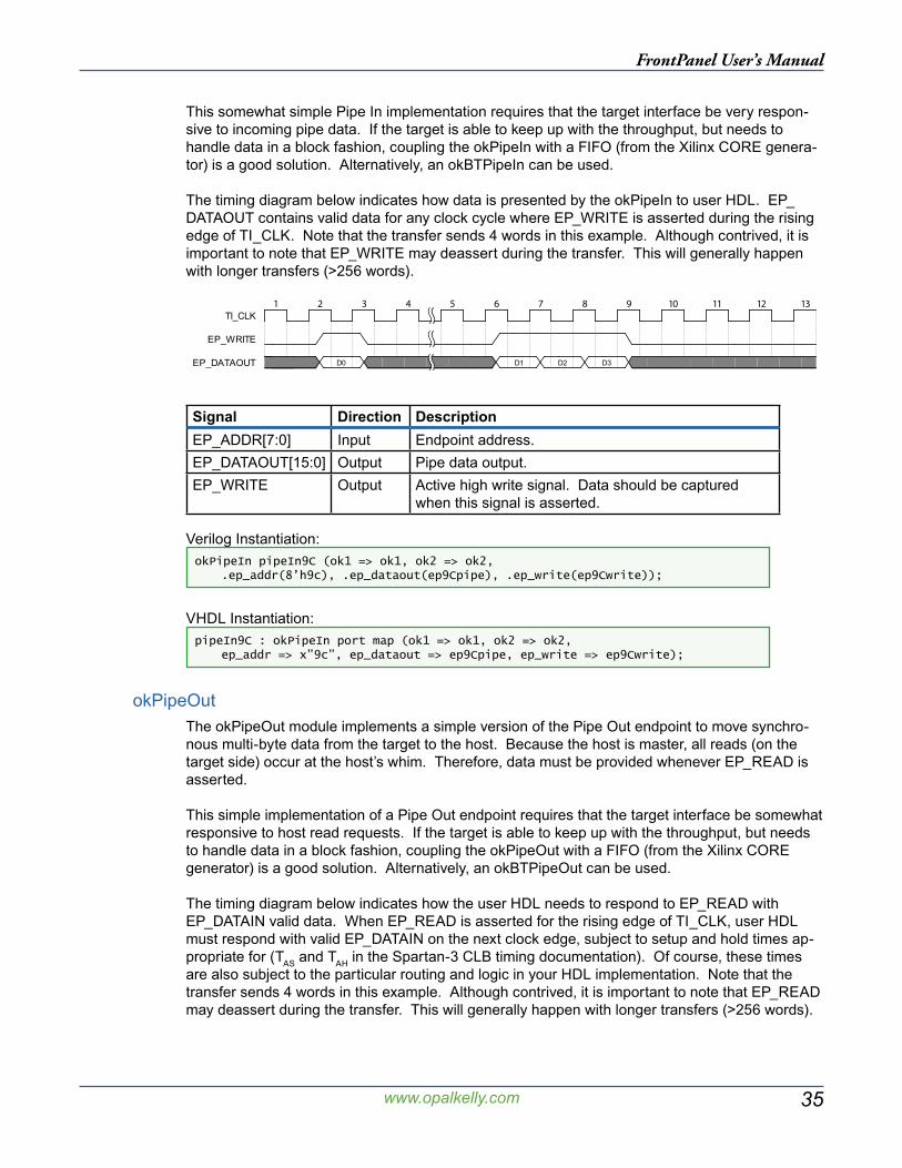
35
FrontPanel User’s Manual
www.opalkelly.com
This somewhat simple Pipe In implementation requires that the target interface be very respon-sive to incoming pipe data. If the target is able to keep up with the throughput, but needs to handle data in a block fashion, coupling the okPipeIn with a FIFO (from the Xilinx CORE genera-tor) is a good solution. Alternatively, an okBTPipeIn can be used.
The timing diagram below indicates how data is presented by the okPipeIn to user HDL. EP_DATAOUT contains valid data for any clock cycle where EP_WRITE is asserted during the rising edge of TI_CLK. Note that the transfer sends 4 words in this example. Although contrived, it is important to note that EP_WRITE may deassert during the transfer. This will generally happen with longer transfers (>256 words).
��� ��� ��� ��� ��� ��� ��� ��� ��� ���� ���� ���� ����
D0 D1 D2 D3
TI_CLK
EP_WRITE
EP_DATAOUT
Signal Direction DescriptionEP_ADDR[7:0] Input Endpoint address.EP_DATAOUT[15:0] Output Pipe data output.EP_WRITE Output Active high write signal. Data should be captured
when this signal is asserted.
Verilog Instantiation:okPipeIn pipeIn9C (ok1 => ok1, ok2 => ok2, .ep_addr(8’h9c), .ep_dataout(ep9Cpipe), .ep_write(ep9Cwrite));
VHDL Instantiation:pipeIn9C : okPipeIn port map (ok1 => ok1, ok2 => ok2, ep_addr => x”9c”, ep_dataout => ep9Cpipe, ep_write => ep9Cwrite);
okPipeOutThe okPipeOut module implements a simple version of the Pipe Out endpoint to move synchro-nous multi-byte data from the target to the host. Because the host is master, all reads (on the target side) occur at the host’s whim. Therefore, data must be provided whenever EP_READ is asserted.
This simple implementation of a Pipe Out endpoint requires that the target interface be somewhat responsive to host read requests. If the target is able to keep up with the throughput, but needs to handle data in a block fashion, coupling the okPipeOut with a FIFO (from the Xilinx CORE generator) is a good solution. Alternatively, an okBTPipeOut can be used.
The timing diagram below indicates how the user HDL needs to respond to EP_READ with EP_DATAIN valid data. When EP_READ is asserted for the rising edge of TI_CLK, user HDL must respond with valid EP_DATAIN on the next clock edge, subject to setup and hold times ap-propriate for (TAS and TAH in the Spartan-3 CLB timing documentation). Of course, these times are also subject to the particular routing and logic in your HDL implementation. Note that the transfer sends 4 words in this example. Although contrived, it is important to note that EP_READ may deassert during the transfer. This will generally happen with longer transfers (>256 words).
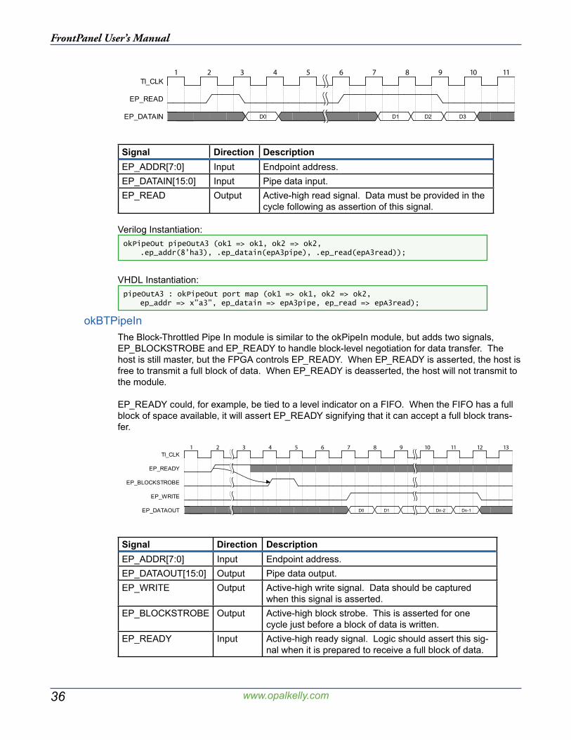
36
FrontPanel User’s Manual
www.opalkelly.com
��� ��� ��� ��� ��� ��� ��� ��� ��� ���� ����
D0 D1 D2 D3
TI_CLK
EP_READ
EP_DATAIN
Signal Direction DescriptionEP_ADDR[7:0] Input Endpoint address.EP_DATAIN[15:0] Input Pipe data input.EP_READ Output Active-high read signal. Data must be provided in the
cycle following as assertion of this signal.
Verilog Instantiation:okPipeOut pipeOutA3 (ok1 => ok1, ok2 => ok2, .ep_addr(8’ha3), .ep_datain(epA3pipe), .ep_read(epA3read));
VHDL Instantiation:pipeOutA3 : okPipeOut port map (ok1 => ok1, ok2 => ok2, ep_addr => x”a3”, ep_datain => epA3pipe, ep_read => epA3read);
okBTPipeInThe Block-Throttled Pipe In module is similar to the okPipeIn module, but adds two signals, EP_BLOCKSTROBE and EP_READY to handle block-level negotiation for data transfer. The host is still master, but the FPGA controls EP_READY. When EP_READY is asserted, the host is free to transmit a full block of data. When EP_READY is deasserted, the host will not transmit to the module.
EP_READY could, for example, be tied to a level indicator on a FIFO. When the FIFO has a full block of space available, it will assert EP_READY signifying that it can accept a full block trans-fer.
��� ��� ��� ��� ��� ��� ��� ��� ��� ���� ���� ���� ����
D0 D1 Dn-1Dn-2
TI_CLK
EP_READY
EP_BLOCKSTROBE
EP_WRITE
EP_DATAOUT
Signal Direction DescriptionEP_ADDR[7:0] Input Endpoint address.EP_DATAOUT[15:0] Output Pipe data output.EP_WRITE Output Active-high write signal. Data should be captured
when this signal is asserted.EP_BLOCKSTROBE Output Active-high block strobe. This is asserted for one
cycle just before a block of data is written.EP_READY Input Active-high ready signal. Logic should assert this sig-
nal when it is prepared to receive a full block of data.
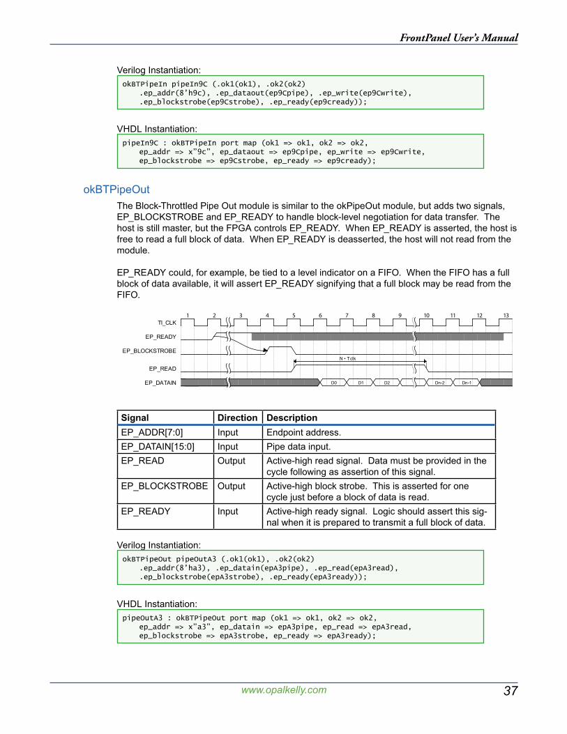
37
FrontPanel User’s Manual
www.opalkelly.com
Verilog Instantiation:okBTPipeIn pipeIn9C (.ok1(ok1), .ok2(ok2) .ep_addr(8’h9c), .ep_dataout(ep9Cpipe), .ep_write(ep9Cwrite), .ep_blockstrobe(ep9Cstrobe), .ep_ready(ep9cready));
VHDL Instantiation:pipeIn9C : okBTPipeIn port map (ok1 => ok1, ok2 => ok2, ep_addr => x”9c”, ep_dataout => ep9Cpipe, ep_write => ep9Cwrite, ep_blockstrobe => ep9Cstrobe, ep_ready => ep9cready);
okBTPipeOutThe Block-Throttled Pipe Out module is similar to the okPipeOut module, but adds two signals, EP_BLOCKSTROBE and EP_READY to handle block-level negotiation for data transfer. The host is still master, but the FPGA controls EP_READY. When EP_READY is asserted, the host is free to read a full block of data. When EP_READY is deasserted, the host will not read from the module.
EP_READY could, for example, be tied to a level indicator on a FIFO. When the FIFO has a full block of data available, it will assert EP_READY signifying that a full block may be read from the FIFO.
��� ��� ��� ��� ��� ��� ��� ��� ��� ���� ���� ���� ����
D0 D1 Dn-1Dn-2
N • Tclk
D2
TI_CLK
EP_READY
EP_BLOCKSTROBE
EP_READ
EP_DATAIN
Signal Direction DescriptionEP_ADDR[7:0] Input Endpoint address.EP_DATAIN[15:0] Input Pipe data input.EP_READ Output Active-high read signal. Data must be provided in the
cycle following as assertion of this signal.EP_BLOCKSTROBE Output Active-high block strobe. This is asserted for one
cycle just before a block of data is read.EP_READY Input Active-high ready signal. Logic should assert this sig-
nal when it is prepared to transmit a full block of data.
Verilog Instantiation:okBTPipeOut pipeOutA3 (.ok1(ok1), .ok2(ok2) .ep_addr(8’ha3), .ep_datain(epA3pipe), .ep_read(epA3read), .ep_blockstrobe(epA3strobe), .ep_ready(epA3ready));
VHDL Instantiation:pipeOutA3 : okBTPipeOut port map (ok1 => ok1, ok2 => ok2, ep_addr => x”a3”, ep_datain => epA3pipe, ep_read => epA3read, ep_blockstrobe => epA3strobe, ep_ready => epA3ready);
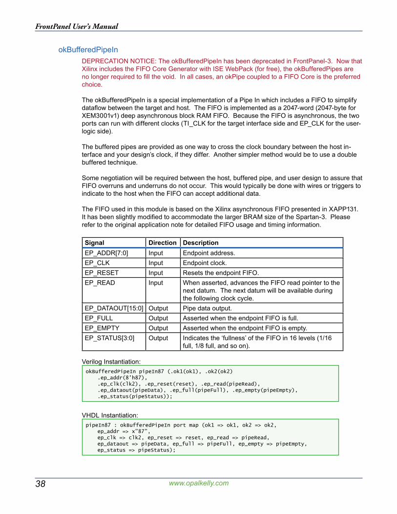
38
FrontPanel User’s Manual
www.opalkelly.com
okBufferedPipeInDEPRECATION NOTICE: The okBufferedPipeIn has been deprecated in FrontPanel-3. Now that Xilinx includes the FIFO Core Generator with ISE WebPack (for free), the okBufferedPipes are no longer required to fill the void. In all cases, an okPipe coupled to a FIFO Core is the preferred choice.
The okBufferedPipeIn is a special implementation of a Pipe In which includes a FIFO to simplify dataflow between the target and host. The FIFO is implemented as a 2047-word (2047-byte for XEM3001v1) deep asynchronous block RAM FIFO. Because the FIFO is asynchronous, the two ports can run with different clocks (TI_CLK for the target interface side and EP_CLK for the user-logic side).
The buffered pipes are provided as one way to cross the clock boundary between the host in-terface and your design’s clock, if they differ. Another simpler method would be to use a double buffered technique.
Some negotiation will be required between the host, buffered pipe, and user design to assure that FIFO overruns and underruns do not occur. This would typically be done with wires or triggers to indicate to the host when the FIFO can accept additional data.
The FIFO used in this module is based on the Xilinx asynchronous FIFO presented in XAPP131. It has been slightly modified to accommodate the larger BRAM size of the Spartan-3. Please refer to the original application note for detailed FIFO usage and timing information.
Signal Direction DescriptionEP_ADDR[7:0] Input Endpoint address.EP_CLK Input Endpoint clock.EP_RESET Input Resets the endpoint FIFO.EP_READ Input When asserted, advances the FIFO read pointer to the
next datum. The next datum will be available during the following clock cycle.
EP_DATAOUT[15:0] Output Pipe data output.EP_FULL Output Asserted when the endpoint FIFO is full.EP_EMPTY Output Asserted when the endpoint FIFO is empty.EP_STATUS[3:0] Output Indicates the ‘fullness’ of the FIFO in 16 levels (1/16
full, 1/8 full, and so on).
Verilog Instantiation:okBufferedPipeIn pipeIn87 (.ok1(ok1), .ok2(ok2) .ep_addr(8’h87), .ep_clk(clk2), .ep_reset(reset), .ep_read(pipeRead), .ep_dataout(pipeData), .ep_full(pipeFull), .ep_empty(pipeEmpty), .ep_status(pipeStatus));
VHDL Instantiation:pipeIn87 : okBufferedPipeIn port map (ok1 => ok1, ok2 => ok2, ep_addr => x”87”, ep_clk => clk2, ep_reset => reset, ep_read => pipeRead, ep_dataout => pipeData, ep_full => pipeFull, ep_empty => pipeEmpty, ep_status => pipeStatus);
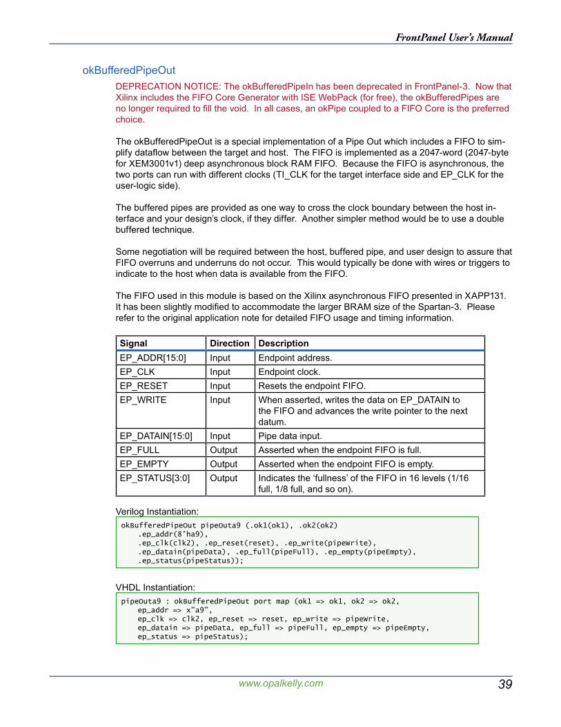
39
FrontPanel User’s Manual
www.opalkelly.com
okBufferedPipeOutDEPRECATION NOTICE: The okBufferedPipeIn has been deprecated in FrontPanel-3. Now that Xilinx includes the FIFO Core Generator with ISE WebPack (for free), the okBufferedPipes are no longer required to fill the void. In all cases, an okPipe coupled to a FIFO Core is the preferred choice.
The okBufferedPipeOut is a special implementation of a Pipe Out which includes a FIFO to sim-plify dataflow between the target and host. The FIFO is implemented as a 2047-word (2047-byte for XEM3001v1) deep asynchronous block RAM FIFO. Because the FIFO is asynchronous, the two ports can run with different clocks (TI_CLK for the target interface side and EP_CLK for the user-logic side).
The buffered pipes are provided as one way to cross the clock boundary between the host in-terface and your design’s clock, if they differ. Another simpler method would be to use a double buffered technique.
Some negotiation will be required between the host, buffered pipe, and user design to assure that FIFO overruns and underruns do not occur. This would typically be done with wires or triggers to indicate to the host when data is available from the FIFO.
The FIFO used in this module is based on the Xilinx asynchronous FIFO presented in XAPP131. It has been slightly modified to accommodate the larger BRAM size of the Spartan-3. Please refer to the original application note for detailed FIFO usage and timing information.
Signal Direction DescriptionEP_ADDR[15:0] Input Endpoint address.EP_CLK Input Endpoint clock.EP_RESET Input Resets the endpoint FIFO.EP_WRITE Input When asserted, writes the data on EP_DATAIN to
the FIFO and advances the write pointer to the next datum.
EP_DATAIN[15:0] Input Pipe data input.EP_FULL Output Asserted when the endpoint FIFO is full.EP_EMPTY Output Asserted when the endpoint FIFO is empty.EP_STATUS[3:0] Output Indicates the ‘fullness’ of the FIFO in 16 levels (1/16
full, 1/8 full, and so on).
Verilog Instantiation:okBufferedPipeOut pipeOuta9 (.ok1(ok1), .ok2(ok2) .ep_addr(8’ha9), .ep_clk(clk2), .ep_reset(reset), .ep_write(pipeWrite), .ep_datain(pipeData), .ep_full(pipeFull), .ep_empty(pipeEmpty), .ep_status(pipeStatus));
VHDL Instantiation:pipeOuta9 : okBufferedPipeOut port map (ok1 => ok1, ok2 => ok2, ep_addr => x”a9”, ep_clk => clk2, ep_reset => reset, ep_write => pipeWrite, ep_datain => pipeData, ep_full => pipeFull, ep_empty => pipeEmpty, ep_status => pipeStatus);

40
FrontPanel User’s Manual
www.opalkelly.com
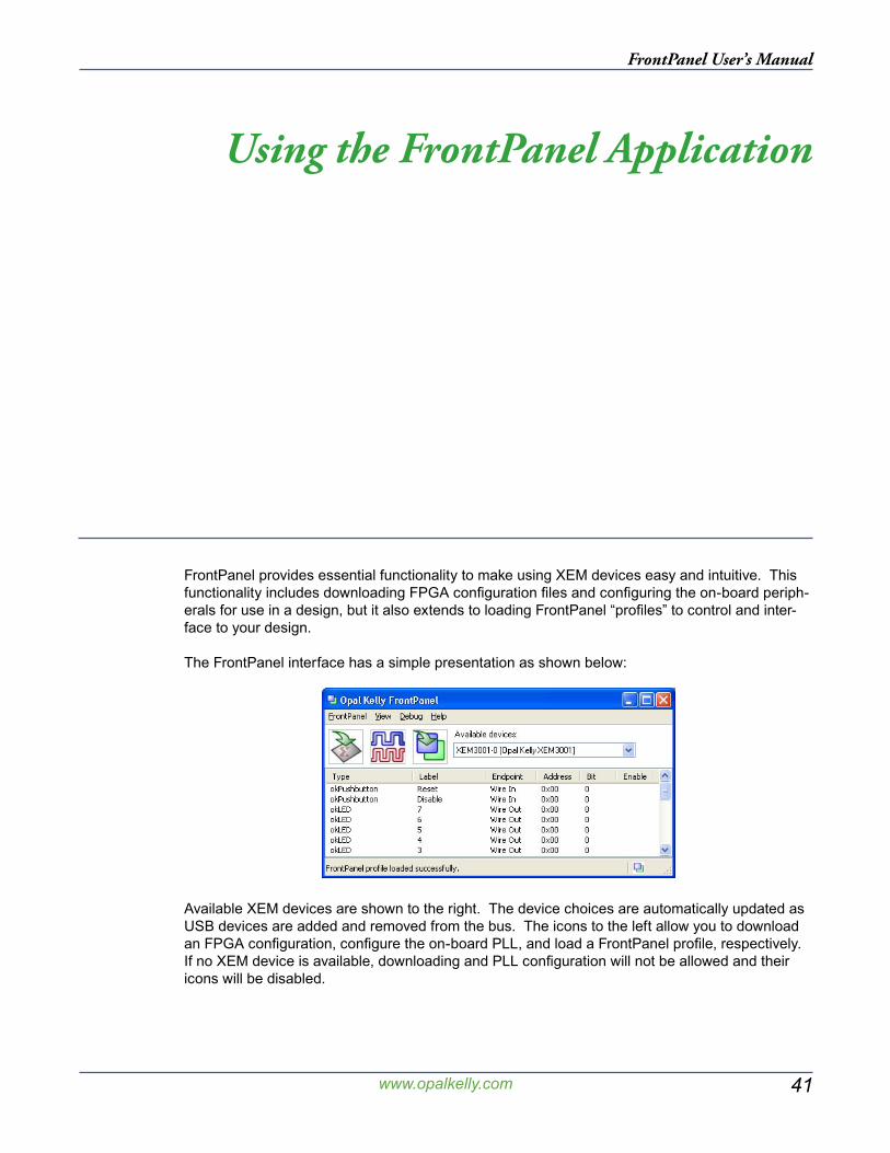
41
FrontPanel User’s Manual
www.opalkelly.com
Using the FrontPanel Application
FrontPanel provides essential functionality to make using XEM devices easy and intuitive. This functionality includes downloading FPGA configuration files and configuring the on-board periph-erals for use in a design, but it also extends to loading FrontPanel “profiles” to control and inter-face to your design.
The FrontPanel interface has a simple presentation as shown below:
Available XEM devices are shown to the right. The device choices are automatically updated as USB devices are added and removed from the bus. The icons to the left allow you to download an FPGA configuration, configure the on-board PLL, and load a FrontPanel profile, respectively. If no XEM device is available, downloading and PLL configuration will not be allowed and their icons will be disabled.
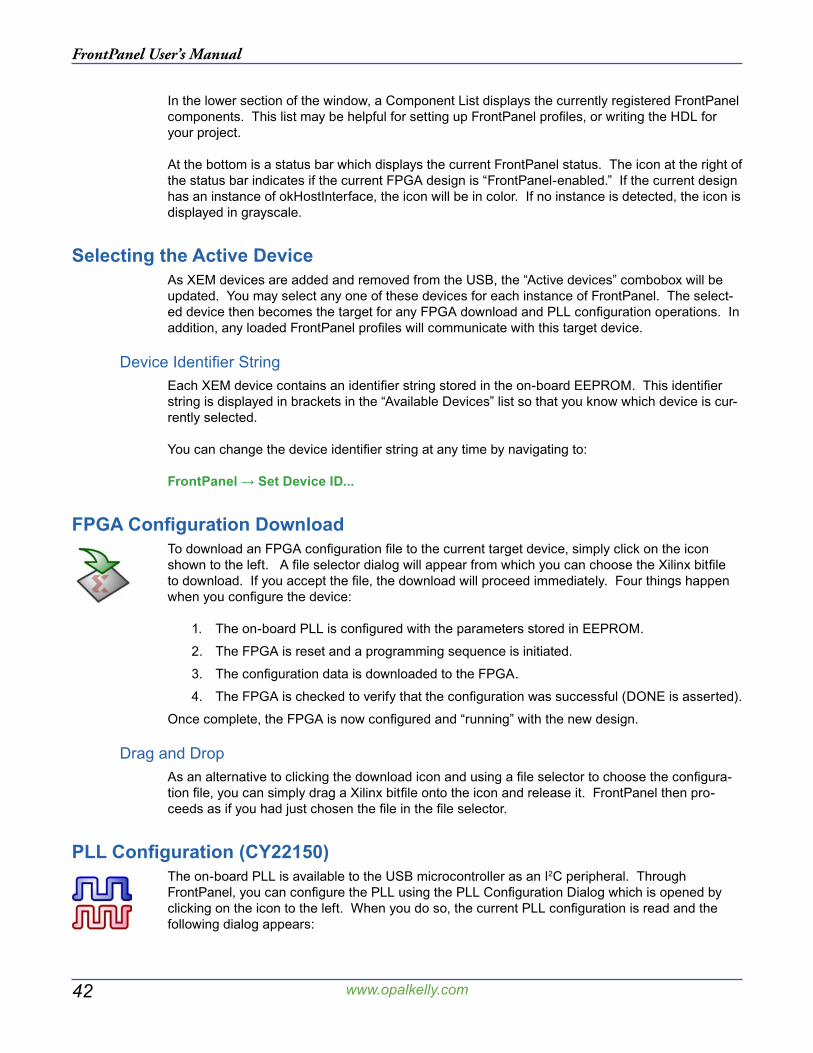
42
FrontPanel User’s Manual
www.opalkelly.com
In the lower section of the window, a Component List displays the currently registered FrontPanel components. This list may be helpful for setting up FrontPanel profiles, or writing the HDL for your project.
At the bottom is a status bar which displays the current FrontPanel status. The icon at the right of the status bar indicates if the current FPGA design is “FrontPanel-enabled.” If the current design has an instance of okHostInterface, the icon will be in color. If no instance is detected, the icon is displayed in grayscale.
Selecting the Active DeviceAs XEM devices are added and removed from the USB, the “Active devices” combobox will be updated. You may select any one of these devices for each instance of FrontPanel. The select-ed device then becomes the target for any FPGA download and PLL configuration operations. In addition, any loaded FrontPanel profiles will communicate with this target device.
Device Identifier StringEach XEM device contains an identifier string stored in the on-board EEPROM. This identifier string is displayed in brackets in the “Available Devices” list so that you know which device is cur-rently selected.
You can change the device identifier string at any time by navigating to:
FrontPanel → Set Device ID...
FPGA Configuration DownloadTo download an FPGA configuration file to the current target device, simply click on the icon shown to the left. A file selector dialog will appear from which you can choose the Xilinx bitfile to download. If you accept the file, the download will proceed immediately. Four things happen when you configure the device:
1. The on-board PLL is configured with the parameters stored in EEPROM.
2. The FPGA is reset and a programming sequence is initiated.
3. The configuration data is downloaded to the FPGA.
4. The FPGA is checked to verify that the configuration was successful (DONE is asserted).
Once complete, the FPGA is now configured and “running” with the new design.
Drag and DropAs an alternative to clicking the download icon and using a file selector to choose the configura-tion file, you can simply drag a Xilinx bitfile onto the icon and release it. FrontPanel then pro-ceeds as if you had just chosen the file in the file selector.
PLL Configuration (CY22150)The on-board PLL is available to the USB microcontroller as an I2C peripheral. Through FrontPanel, you can configure the PLL using the PLL Configuration Dialog which is opened by clicking on the icon to the left. When you do so, the current PLL configuration is read and the following dialog appears:
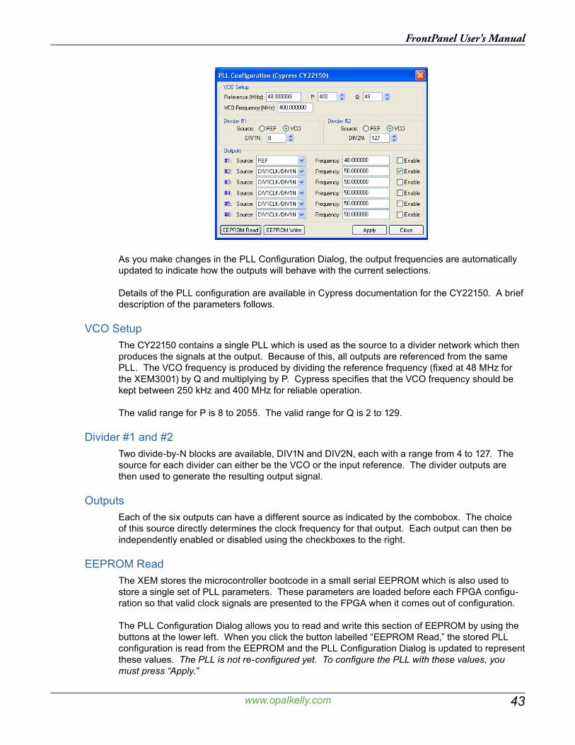
43
FrontPanel User’s Manual
www.opalkelly.com
As you make changes in the PLL Configuration Dialog, the output frequencies are automatically updated to indicate how the outputs will behave with the current selections.
Details of the PLL configuration are available in Cypress documentation for the CY22150. A brief description of the parameters follows.
VCO SetupThe CY22150 contains a single PLL which is used as the source to a divider network which then produces the signals at the output. Because of this, all outputs are referenced from the same PLL. The VCO frequency is produced by dividing the reference frequency (fixed at 48 MHz for the XEM3001) by Q and multiplying by P. Cypress specifies that the VCO frequency should be kept between 250 kHz and 400 MHz for reliable operation.
The valid range for P is 8 to 2055. The valid range for Q is 2 to 129.
Divider #1 and #2Two divide-by-N blocks are available, DIV1N and DIV2N, each with a range from 4 to 127. The source for each divider can either be the VCO or the input reference. The divider outputs are then used to generate the resulting output signal.
OutputsEach of the six outputs can have a different source as indicated by the combobox. The choice of this source directly determines the clock frequency for that output. Each output can then be independently enabled or disabled using the checkboxes to the right.
EEPROM ReadThe XEM stores the microcontroller bootcode in a small serial EEPROM which is also used to store a single set of PLL parameters. These parameters are loaded before each FPGA configu-ration so that valid clock signals are presented to the FPGA when it comes out of configuration.
The PLL Configuration Dialog allows you to read and write this section of EEPROM by using the buttons at the lower left. When you click the button labelled “EEPROM Read,” the stored PLL configuration is read from the EEPROM and the PLL Configuration Dialog is updated to represent these values. The PLL is not re-configured yet. To configure the PLL with these values, you must press “Apply.”
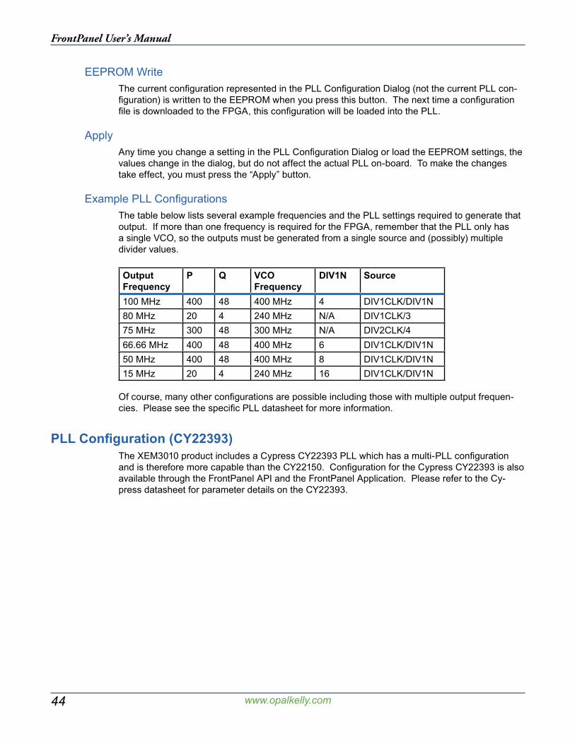
44
FrontPanel User’s Manual
www.opalkelly.com
EEPROM WriteThe current configuration represented in the PLL Configuration Dialog (not the current PLL con-figuration) is written to the EEPROM when you press this button. The next time a configuration file is downloaded to the FPGA, this configuration will be loaded into the PLL.
ApplyAny time you change a setting in the PLL Configuration Dialog or load the EEPROM settings, the values change in the dialog, but do not affect the actual PLL on-board. To make the changes take effect, you must press the “Apply” button.
Example PLL ConfigurationsThe table below lists several example frequencies and the PLL settings required to generate that output. If more than one frequency is required for the FPGA, remember that the PLL only has a single VCO, so the outputs must be generated from a single source and (possibly) multiple divider values.
OutputFrequency
P Q VCOFrequency
DIV1N Source
100 MHz 400 48 400 MHz 4 DIV1CLK/DIV1N80 MHz 20 4 240 MHz N/A DIV1CLK/375 MHz 300 48 300 MHz N/A DIV2CLK/466.66 MHz 400 48 400 MHz 6 DIV1CLK/DIV1N50 MHz 400 48 400 MHz 8 DIV1CLK/DIV1N15 MHz 20 4 240 MHz 16 DIV1CLK/DIV1N
Of course, many other configurations are possible including those with multiple output frequen-cies. Please see the specific PLL datasheet for more information.
PLL Configuration (CY22393)The XEM3010 product includes a Cypress CY22393 PLL which has a multi-PLL configuration and is therefore more capable than the CY22150. Configuration for the Cypress CY22393 is also available through the FrontPanel API and the FrontPanel Application. Please refer to the Cy-press datasheet for parameter details on the CY22393.
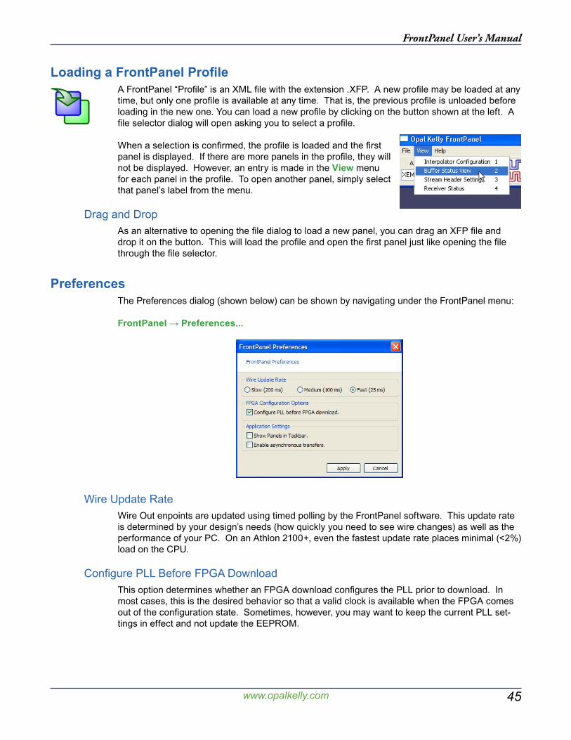
45
FrontPanel User’s Manual
www.opalkelly.com
Loading a FrontPanel ProfileA FrontPanel “Profile” is an XML file with the extension .XFP. A new profile may be loaded at any time, but only one profile is available at any time. That is, the previous profile is unloaded before loading in the new one. You can load a new profile by clicking on the button shown at the left. A file selector dialog will open asking you to select a profile.
When a selection is confirmed, the profile is loaded and the first panel is displayed. If there are more panels in the profile, they will not be displayed. However, an entry is made in the View menu for each panel in the profile. To open another panel, simply select that panel’s label from the menu.
Drag and DropAs an alternative to opening the file dialog to load a new panel, you can drag an XFP file and drop it on the button. This will load the profile and open the first panel just like opening the file through the file selector.
PreferencesThe Preferences dialog (shown below) can be shown by navigating under the FrontPanel menu:
FrontPanel → Preferences...
Wire Update RateWire Out enpoints are updated using timed polling by the FrontPanel software. This update rate is determined by your design’s needs (how quickly you need to see wire changes) as well as the performance of your PC. On an Athlon 2100+, even the fastest update rate places minimal (<2%) load on the CPU.
Configure PLL Before FPGA DownloadThis option determines whether an FPGA download configures the PLL prior to download. In most cases, this is the desired behavior so that a valid clock is available when the FPGA comes out of the configuration state. Sometimes, however, you may want to keep the current PLL set-tings in effect and not update the EEPROM.
46
FrontPanel User’s Manual
www.opalkelly.com
Show Panels in TaskbarWhen unchecked, each FrontPanel “panel” is displayed in a toolbox window which does not reg-ister with the taskbar. When checked, these panels will register with the taskbar so that you can easily select a particular panel.
Enable Asynchronous TransfersAsynchronous transfers allow USB transfer requests to be queued and sequenced by the oper-ating system. This decreases software overhead and increases overall throughput. However, many Windows 2000-based machines have problems with asynchronous transfers and may not communicate with the FPGA properly when this feature is enabled.
You may find that you need to disable asynchronous transfers before any FPGA communication. Otherwise, the communication link may become “tainted” and will not work. Therefore, if you experience problems with Windows 2000 and FrontPanel communication, we advise that you dis-able asynchronous transfers before communicating with your board.
From within your own software, there is an API method to control this feature.
47
FrontPanel User’s Manual
www.opalkelly.com
Component XML
FrontPanel user interfaces (“panels”) are constructed from “components” - graphical devices that interface to your design or serve some decorative function. The interfaces are described in FrontPanel “profiles” which are written in a text file format known as XML. The XML profile con-tains structure which defines where each component exists on a panel as well as the connections that component has to your FPGA design. FrontPanel XML files end with the extension XFP.
XMLXML stands for eXtensible Markup Language and is used in documents containing structured information. The syntax for XML is defined at http://www.w3.org/TR/WD-xml. For its part, XML does not define the content but rather how the content is organized. FrontPanel uses XML because the standard is well-known and there are many tools available to read, write, edit, and parse the content. It is also easily human-readable so you can read and write FrontPanel profiles in a text-editor with ease.
A complete tutorial of XML is beyond the scope of this text. What is provided here is a basic tuto-rial of the aspects of XML required to compose FrontPanel profiles. Please refer to the enormous on-line resources available for a complete understanding of XML, its applications, and the tools available for working with XML.
Basic Structure for FrontPanelThe basic FrontPanel XFP file has the following structure:
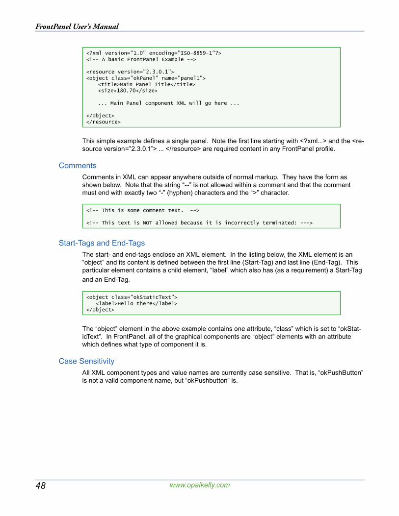
48
FrontPanel User’s Manual
www.opalkelly.com
<?xml version=”1.0” encoding=”ISO-8859-1”?><!-- A basic FrontPanel Example -->
<resource version=”2.3.0.1”><object class=”okPanel” name=”panel1”> <title>Main Panel Title</title> <size>180,70</size>
... Main Panel component XML will go here ...
</object></resource>
This simple example defines a single panel. Note the first line starting with <?xml...> and the <re-source version=”2.3.0.1”> ... </resource> are required content in any FrontPanel profile.
CommentsComments in XML can appear anywhere outside of normal markup. They have the form as shown below. Note that the string “--” is not allowed within a comment and that the comment must end with exactly two “-” (hyphen) characters and the “>” character.
<!-- This is some comment text. -->
<!-- This text is NOT allowed because it is incorrectly terminated: --->
Start-Tags and End-TagsThe start- and end-tags enclose an XML element. In the listing below, the XML element is an “object” and its content is defined between the first line (Start-Tag) and last line (End-Tag). This particular element contains a child element, “label” which also has (as a requirement) a Start-Tag and an End-Tag.
<object class=”okStaticText”> <label>Hello there</label></object>
The “object” element in the above example contains one attribute, “class” which is set to “okStat-icText”. In FrontPanel, all of the graphical components are “object” elements with an attribute which defines what type of component it is.
Case SensitivityAll XML component types and value names are currently case sensitive. That is, “okPushButton” is not a valid component name, but “okPushbutton” is.
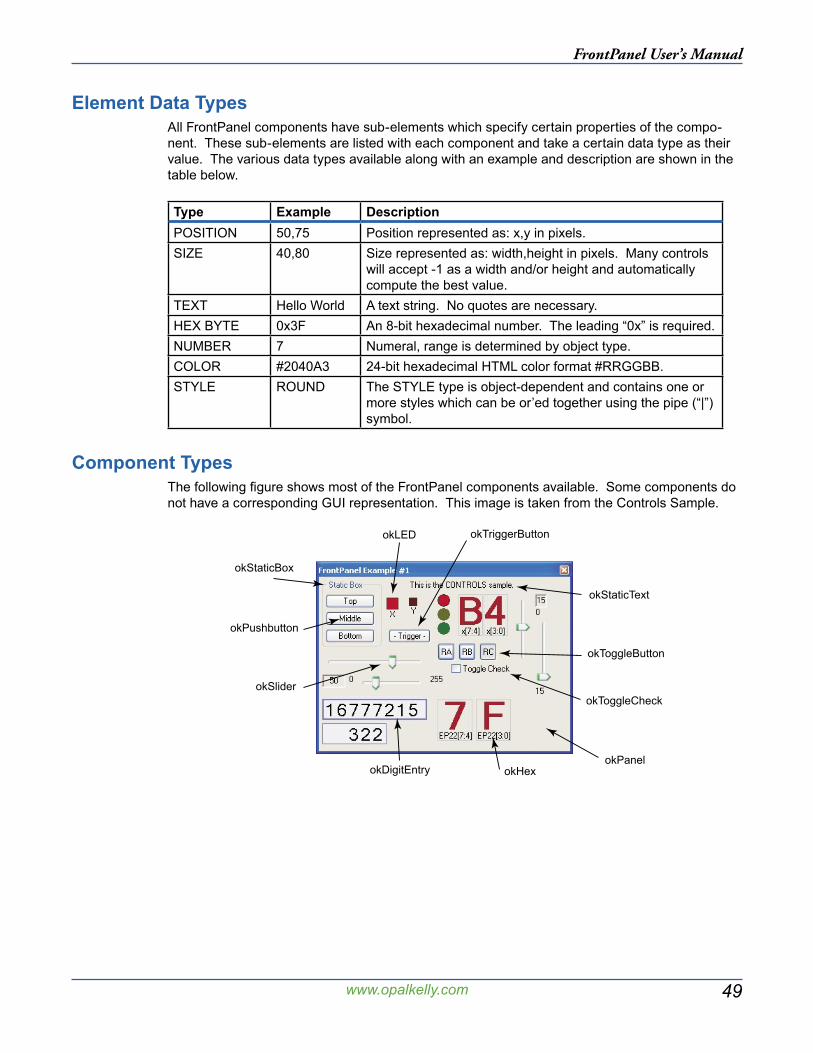
49
FrontPanel User’s Manual
www.opalkelly.com
Element Data TypesAll FrontPanel components have sub-elements which specify certain properties of the compo-nent. These sub-elements are listed with each component and take a certain data type as their value. The various data types available along with an example and description are shown in the table below.
Type Example DescriptionPOSITION 50,75 Position represented as: x,y in pixels.SIZE 40,80 Size represented as: width,height in pixels. Many controls
will accept -1 as a width and/or height and automatically compute the best value.
TEXT Hello World A text string. No quotes are necessary.HEX BYTE 0x3F An 8-bit hexadecimal number. The leading “0x” is required.NUMBER 7 Numeral, range is determined by object type.COLOR #2040A3 24-bit hexadecimal HTML color format #RRGGBB.STYLE ROUND The STYLE type is object-dependent and contains one or
more styles which can be or’ed together using the pipe (“|”) symbol.
Component TypesThe following figure shows most of the FrontPanel components available. Some components do not have a corresponding GUI representation. This image is taken from the Controls Sample.
okStaticText
okStaticBox
okPushbutton
okHex
okSlider
okTriggerButton
okToggleButton
okToggleCheck
okDigitEntryokPanel
okLED
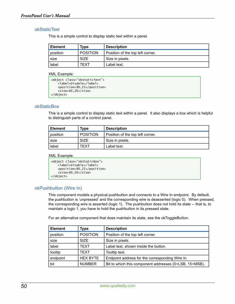
50
FrontPanel User’s Manual
www.opalkelly.com
okStaticTextThis is a simple control to display static text within a panel.
Element Type Descriptionposition POSITION Position of the top left corner.size SIZE Size in pixels.label TEXT Label text.
XML Example:<object class=”okStaticText”> <label>Disable</label> <position>90,25</position> <size>60,20</size></object>
okStaticBoxThis is a simple control to display static text within a panel. It also displays a box which is helpful to distinguish parts of a control panel.
Element Type Descriptionposition POSITION Position of the top left corner.size SIZE Size in pixels.label TEXT Label text.
XML Example:<object class=”okStaticBox”> <label>Disable</label> <position>90,25</position> <size>60,20</size></object>
okPushbutton (Wire In)This component models a physical pushbutton and connects to a Wire In endpoint. By default, the pushbutton is ‘unpressed’ and the corresponding wire is deasserted (logic 0). When pressed, the corresponding wire is asserted (logic 1). The pushbutton does not hold its state -- that is, to maintain a logic 1, you have to hold the pushbutton in its pressed state.
For an alternative component that does maintain its state, see the okToggleButton.
Element Type Descriptionposition POSITION Position of the top left corner.size SIZE Size in pixels.label TEXT Label text, shown inside the button.tooltip TEXT Tooltip text.endpoint HEX BYTE Endpoint address for the corresponding Wire In.bit NUMBER Bit to which this component addresses (0=LSB, 15=MSB).
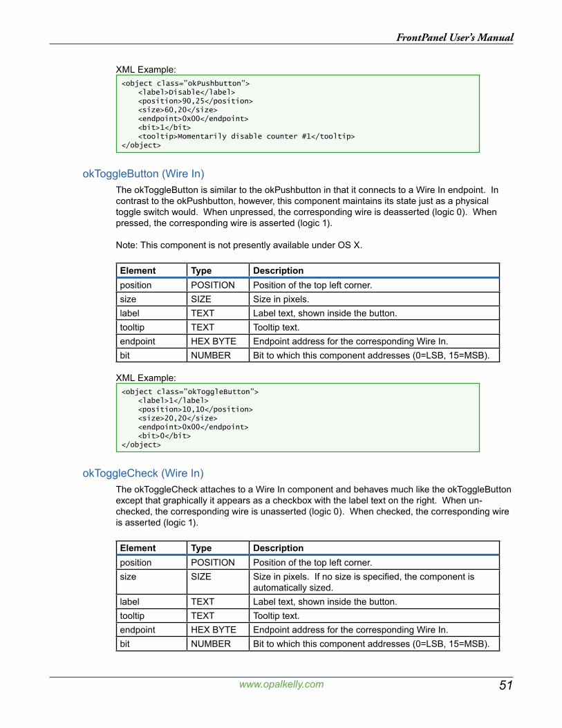
51
FrontPanel User’s Manual
www.opalkelly.com
XML Example:<object class=”okPushbutton”> <label>Disable</label> <position>90,25</position> <size>60,20</size> <endpoint>0x00</endpoint> <bit>1</bit> <tooltip>Momentarily disable counter #1</tooltip></object>
okToggleButton (Wire In)The okToggleButton is similar to the okPushbutton in that it connects to a Wire In endpoint. In contrast to the okPushbutton, however, this component maintains its state just as a physical toggle switch would. When unpressed, the corresponding wire is deasserted (logic 0). When pressed, the corresponding wire is asserted (logic 1).
Note: This component is not presently available under OS X.
Element Type Descriptionposition POSITION Position of the top left corner.size SIZE Size in pixels.label TEXT Label text, shown inside the button.tooltip TEXT Tooltip text.endpoint HEX BYTE Endpoint address for the corresponding Wire In.bit NUMBER Bit to which this component addresses (0=LSB, 15=MSB).
XML Example:<object class=”okToggleButton”> <label>1</label> <position>10,10</position> <size>20,20</size> <endpoint>0x00</endpoint> <bit>0</bit></object>
okToggleCheck (Wire In)The okToggleCheck attaches to a Wire In component and behaves much like the okToggleButton except that graphically it appears as a checkbox with the label text on the right. When un-checked, the corresponding wire is unasserted (logic 0). When checked, the corresponding wire is asserted (logic 1).
Element Type Descriptionposition POSITION Position of the top left corner.size SIZE Size in pixels. If no size is specified, the component is
automatically sized.label TEXT Label text, shown inside the button.tooltip TEXT Tooltip text.endpoint HEX BYTE Endpoint address for the corresponding Wire In.bit NUMBER Bit to which this component addresses (0=LSB, 15=MSB).
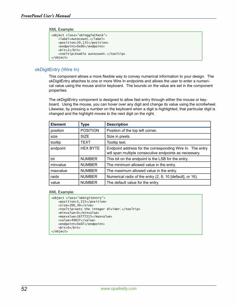
52
FrontPanel User’s Manual
www.opalkelly.com
XML Example:<object class=”okToggleCheck”> <label>Autocount.</label> <position>20,135</position> <endpoint>0x00</endpoint> <bit>2</bit> <tooltip>Enable autocount.</tooltip></object>
okDigitEntry (Wire In)This component allows a more flexible way to convey numerical information to your design. The okDigitEntry attaches to one or more Wire In endpoints and allows the user to enter a numeri-cal value using the mouse and/or keyboard. The bounds on the value are set in the component properties.
The okDigitEntry component is designed to allow fast entry through either the mouse or key-board. Using the mouse, you can hover over any digit and change its value using the scrollwheel. Likewise, by pressing a number on the keyboard when a digit is highlighted, that particular digit is changed and the highlight moves to the next digit on the right.
Element Type Descriptionposition POSITION Position of the top left corner.size SIZE Size in pixels.tooltip TEXT Tooltip text.endpoint HEX BYTE Endpoint address for the corresponding Wire In. The entry
will span multiple consecutive endpoints as necessary.bit NUMBER This bit on the endpoint is the LSB for the entry.minvalue NUMBER The minimum allowed value in the entry.maxvalue NUMBER The maximum allowed value in the entry.raidx NUMBER Numerical radix of the entry (2, 8, 10 [default], or 16).value NUMBER The default value for the entry.
XML Example:<object class=”okDigitEntry”> <position>5,215</position> <size>200,30</size> <tooltip>Sets the integer divider.</tooltip> <minvalue>0</minvalue> <maxvalue>16777215</maxvalue> <value>49837</value> <endpoint>0x07</endpoint> <bit>0</bit></object>
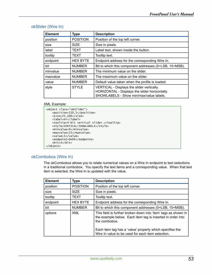
53
FrontPanel User’s Manual
www.opalkelly.com
okSlider (Wire In)
Element Type Descriptionposition POSITION Position of the top left corner.size SIZE Size in pixels.label TEXT Label text, shown inside the button.tooltip TEXT Tooltip text.endpoint HEX BYTE Endpoint address for the corresponding Wire In.bit NUMBER Bit to which this component addresses (0=LSB, 15=MSB).minvalue NUMBER The minimum value on the slider.maxvalue NUMBER The maximum value on the slider.value NUMBER Default value taken when the profile is loaded.style STYLE VERTICAL - Displays the slider vertically.
HORIZONTAL - Displays the silder horizontally.SHOWLABELS - Show min/max/value labels.
XML Example:<object class=”okSlider”> <position>310,5</position> <size>25,100</size> <label>Hi</label> <tooltip>4-bit vertical slider.</tooltip> <style>VERTICAL|SHOWLABELS</style> <minvalue>0</minvalue> <maxvalue>15</maxvalue> <value>3</value> <endpoint>0x04</endpoint> <bit>4</bit></object>
okCombobox (Wire In)The okCombobox allows you to relate numerical values on a Wire In endpoint to text selections in a traditional combobox. You specify the text items and a corresponding value. When that text item is selected, the Wire In is updated with the value.
Element Type Descriptionposition POSITION Position of the top left corner.size SIZE Size in pixels.tooltip TEXT Tooltip text.endpoint HEX BYTE Endpoint address for the corresponding Wire In.bit NUMBER Bit to which this component addresses (0=LSB, 15=MSB).options XML This field is further broken down into ‘item’ tags as shown in
the example below. Each item tag is inserted in order into the combobox.
Each item tag has a ‘value’ property which specifies the Wire In value to be used for each item selection.
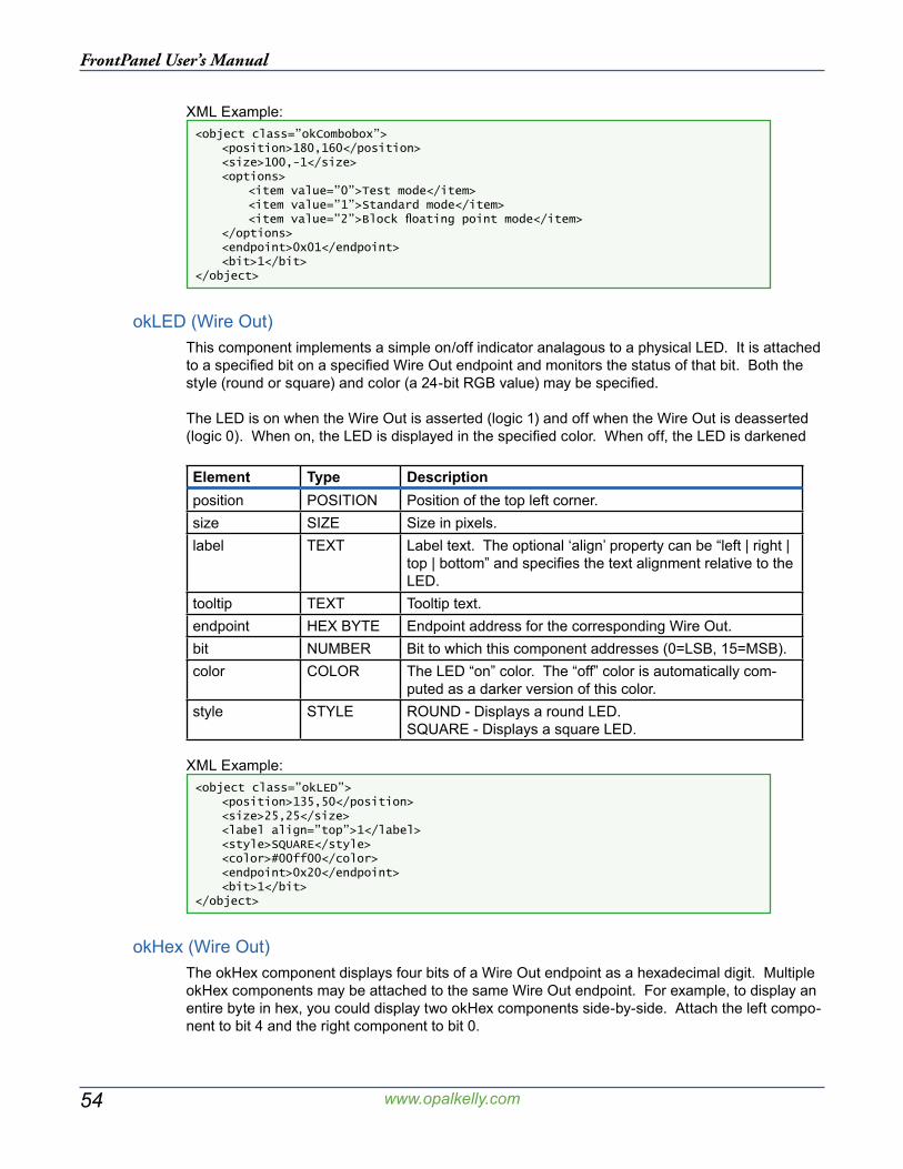
54
FrontPanel User’s Manual
www.opalkelly.com
XML Example:<object class=”okCombobox”> <position>180,160</position> <size>100,-1</size> <options> <item value=”0”>Test mode</item> <item value=”1”>Standard mode</item> <item value=”2”>Block floating point mode</item> </options> <endpoint>0x01</endpoint> <bit>1</bit></object>
okLED (Wire Out)This component implements a simple on/off indicator analagous to a physical LED. It is attached to a specified bit on a specified Wire Out endpoint and monitors the status of that bit. Both the style (round or square) and color (a 24-bit RGB value) may be specified.
The LED is on when the Wire Out is asserted (logic 1) and off when the Wire Out is deasserted (logic 0). When on, the LED is displayed in the specified color. When off, the LED is darkened
Element Type Descriptionposition POSITION Position of the top left corner.size SIZE Size in pixels.label TEXT Label text. The optional ‘align’ property can be “left | right |
top | bottom” and specifies the text alignment relative to the LED.
tooltip TEXT Tooltip text.endpoint HEX BYTE Endpoint address for the corresponding Wire Out.bit NUMBER Bit to which this component addresses (0=LSB, 15=MSB).color COLOR The LED “on” color. The “off” color is automatically com-
puted as a darker version of this color.style STYLE ROUND - Displays a round LED.
SQUARE - Displays a square LED.
XML Example:<object class=”okLED”> <position>135,50</position> <size>25,25</size> <label align=”top”>1</label> <style>SQUARE</style> <color>#00ff00</color> <endpoint>0x20</endpoint> <bit>1</bit></object>
okHex (Wire Out)The okHex component displays four bits of a Wire Out endpoint as a hexadecimal digit. Multiple okHex components may be attached to the same Wire Out endpoint. For example, to display an entire byte in hex, you could display two okHex components side-by-side. Attach the left compo-nent to bit 4 and the right component to bit 0.
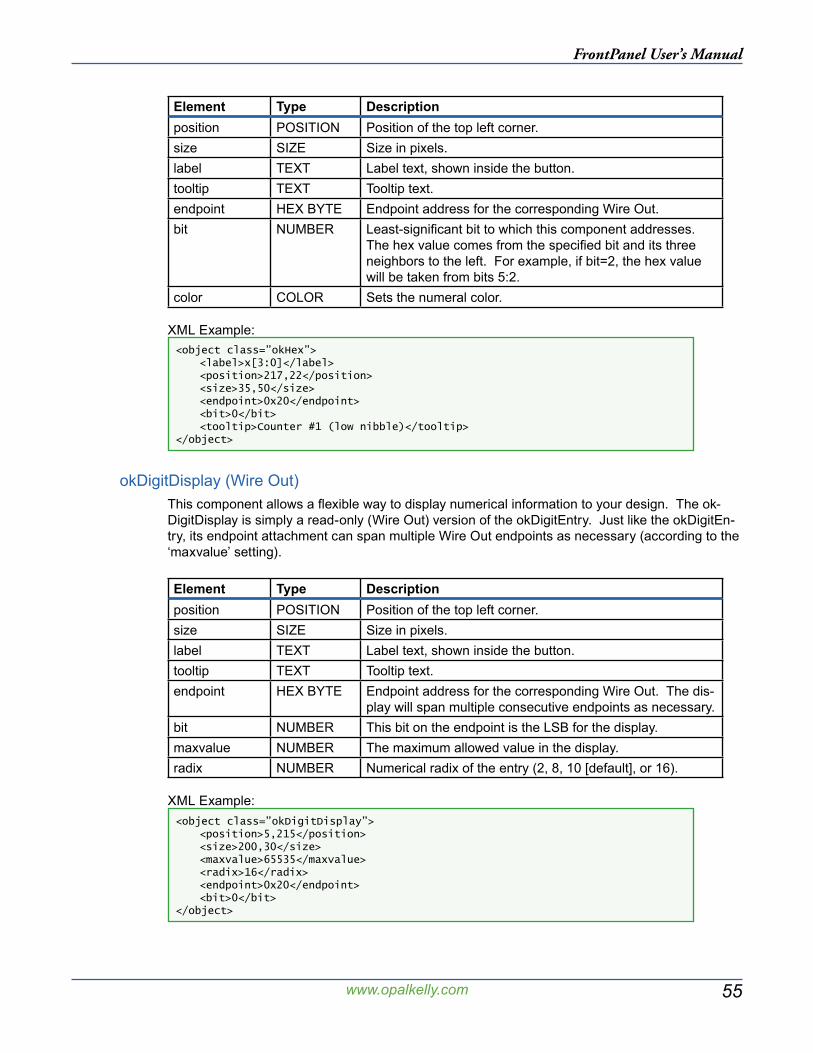
55
FrontPanel User’s Manual
www.opalkelly.com
Element Type Descriptionposition POSITION Position of the top left corner.size SIZE Size in pixels.label TEXT Label text, shown inside the button.tooltip TEXT Tooltip text.endpoint HEX BYTE Endpoint address for the corresponding Wire Out.bit NUMBER Least-significant bit to which this component addresses.
The hex value comes from the specified bit and its three neighbors to the left. For example, if bit=2, the hex value will be taken from bits 5:2.
color COLOR Sets the numeral color.
XML Example:<object class=”okHex”> <label>x[3:0]</label> <position>217,22</position> <size>35,50</size> <endpoint>0x20</endpoint> <bit>0</bit> <tooltip>Counter #1 (low nibble)</tooltip></object>
okDigitDisplay (Wire Out)This component allows a flexible way to display numerical information to your design. The ok-DigitDisplay is simply a read-only (Wire Out) version of the okDigitEntry. Just like the okDigitEn-try, its endpoint attachment can span multiple Wire Out endpoints as necessary (according to the ‘maxvalue’ setting).
Element Type Descriptionposition POSITION Position of the top left corner.size SIZE Size in pixels.label TEXT Label text, shown inside the button.tooltip TEXT Tooltip text.endpoint HEX BYTE Endpoint address for the corresponding Wire Out. The dis-
play will span multiple consecutive endpoints as necessary.bit NUMBER This bit on the endpoint is the LSB for the display.maxvalue NUMBER The maximum allowed value in the display.radix NUMBER Numerical radix of the entry (2, 8, 10 [default], or 16).
XML Example:<object class=”okDigitDisplay”> <position>5,215</position> <size>200,30</size> <maxvalue>65535</maxvalue> <radix>16</radix> <endpoint>0x20</endpoint> <bit>0</bit></object>

56
FrontPanel User’s Manual
www.opalkelly.com
okGauge (Wire Out)The okGauge component is used to display a bar-type indicator horizontally or vertically on the panel. It connects to a Wire Out endpoint and allows a maximum range of 65535 (all 16-bits of a Wire Out). It appropriately selects the proper number of bits for smaller ranges.
Element Type Descriptionposition POSITION Position of the top-left corner.size SIZE Size in pixels.tooltip TEXT Tooltip text.style TEXT Either “HORIZONTAL” or “VERTICAL”endpoint HEX BYTE Endpoint address for the corresponding Wire Out.bit NUMBER This bit on the endpoint is the LSB for the display.range NUMBER The maximum allowed value in the display.
XML Example:<object class=”okGauge”> <position>120,235</position> <size>150,15</size> <style>HORIZONTAL</style> <range>65535</range> <endpoint>0x33</endpoint> <bit>0</bit></object>
okTriggerButton (Trigger In)The okTriggerButton appears identical to the okPushbutton but connects to a Trigger In endpoint. The trigger is activated when the button is pushed (rather than when the button is released).
You may wish to denote that a particular button is a trigger by surrounding the label with hyphens. In the example below, the button label is “- Reset -” to make the button appear different from an okPushbutton.
Element Type Descriptionposition POSITION Position of the top-left corner.size SIZE Size in pixels.label TEXT Label text, shown inside the button.tooltip TEXT Tooltip text.endpoint HEX BYTE Endpoint address for the corresponding Trigger In.bit NUMBER Bit to which this component addresses (0=LSB, 15=MSB).
XML Example:<object class=”okTriggerButton”> <label>- Reset -</label> <position>20,110</position> <size>60,20</size> <endpoint>0x40</endpoint> <bit>0</bit> <tooltip>Reset Counter #2</tooltip></object>
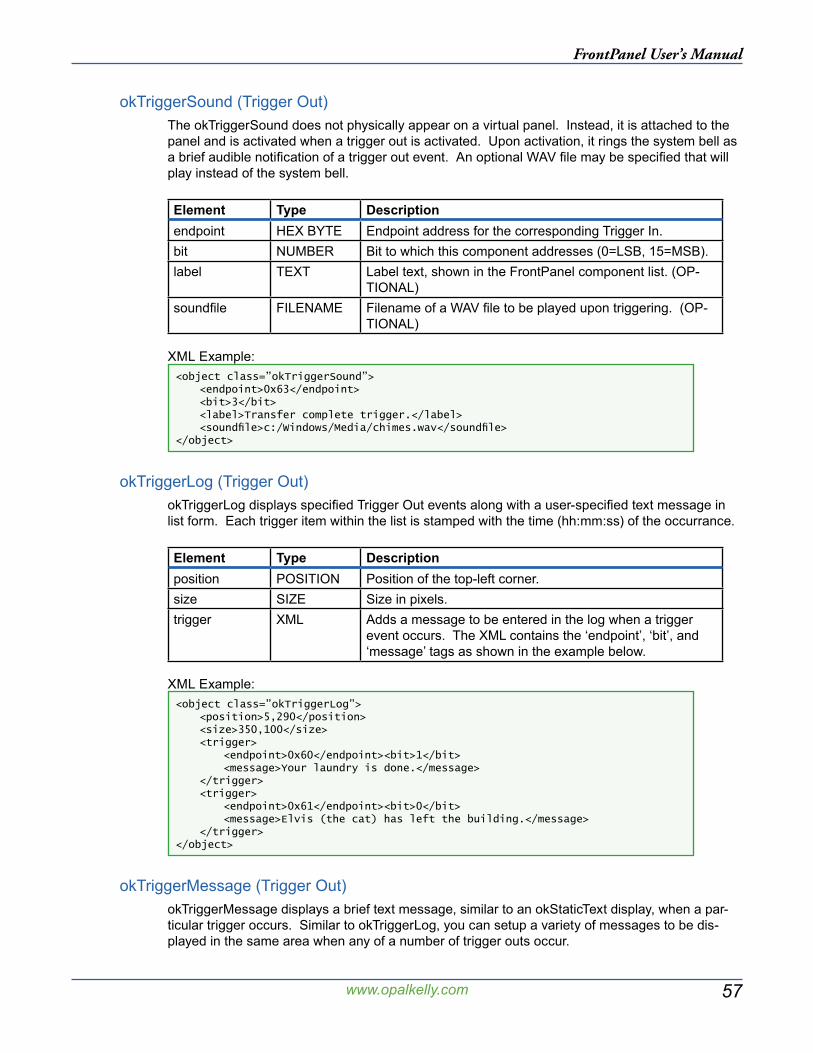
57
FrontPanel User’s Manual
www.opalkelly.com
okTriggerSound (Trigger Out)The okTriggerSound does not physically appear on a virtual panel. Instead, it is attached to the panel and is activated when a trigger out is activated. Upon activation, it rings the system bell as a brief audible notification of a trigger out event. An optional WAV file may be specified that will play instead of the system bell.
Element Type Descriptionendpoint HEX BYTE Endpoint address for the corresponding Trigger In.bit NUMBER Bit to which this component addresses (0=LSB, 15=MSB).label TEXT Label text, shown in the FrontPanel component list. (OP-
TIONAL)soundfile FILENAME Filename of a WAV file to be played upon triggering. (OP-
TIONAL)
XML Example:<object class=”okTriggerSound”> <endpoint>0x63</endpoint> <bit>3</bit> <label>Transfer complete trigger.</label> <soundfile>c:/Windows/Media/chimes.wav</soundfile></object>
okTriggerLog (Trigger Out)okTriggerLog displays specified Trigger Out events along with a user-specified text message in list form. Each trigger item within the list is stamped with the time (hh:mm:ss) of the occurrance.
Element Type Descriptionposition POSITION Position of the top-left corner.size SIZE Size in pixels.trigger XML Adds a message to be entered in the log when a trigger
event occurs. The XML contains the ‘endpoint’, ‘bit’, and ‘message’ tags as shown in the example below.
XML Example:<object class=”okTriggerLog”> <position>5,290</position> <size>350,100</size> <trigger> <endpoint>0x60</endpoint><bit>1</bit> <message>Your laundry is done.</message> </trigger> <trigger> <endpoint>0x61</endpoint><bit>0</bit> <message>Elvis (the cat) has left the building.</message> </trigger></object>
okTriggerMessage (Trigger Out)okTriggerMessage displays a brief text message, similar to an okStaticText display, when a par-ticular trigger occurs. Similar to okTriggerLog, you can setup a variety of messages to be dis-played in the same area when any of a number of trigger outs occur.
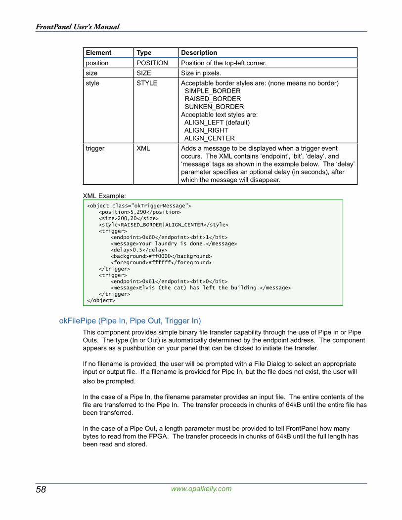
58
FrontPanel User’s Manual
www.opalkelly.com
Element Type Descriptionposition POSITION Position of the top-left corner.size SIZE Size in pixels.style STYLE Acceptable border styles are: (none means no border)
SIMPLE_BORDER RAISED_BORDER SUNKEN_BORDERAcceptable text styles are: ALIGN_LEFT (default) ALIGN_RIGHT ALIGN_CENTER
trigger XML Adds a message to be displayed when a trigger event occurs. The XML contains ‘endpoint’, ‘bit’, ‘delay’, and ‘message’ tags as shown in the example below. The ‘delay’ parameter specifies an optional delay (in seconds), after which the message will disappear.
XML Example:<object class=”okTriggerMessage”> <position>5,290</position> <size>200,20</size> <style>RAISED_BORDER|ALIGN_CENTER</style> <trigger> <endpoint>0x60</endpoint><bit>1</bit> <message>Your laundry is done.</message> <delay>0.5</delay> <background>#ff0000</background> <foreground>#ffffff</foreground> </trigger> <trigger> <endpoint>0x61</endpoint><bit>0</bit> <message>Elvis (the cat) has left the building.</message> </trigger></object>
okFilePipe (Pipe In, Pipe Out, Trigger In)This component provides simple binary file transfer capability through the use of Pipe In or Pipe Outs. The type (In or Out) is automatically determined by the endpoint address. The component appears as a pushbutton on your panel that can be clicked to initiate the transfer.
If no filename is provided, the user will be prompted with a File Dialog to select an appropriate input or output file. If a filename is provided for Pipe In, but the file does not exist, the user will also be prompted.
In the case of a Pipe In, the filename parameter provides an input file. The entire contents of the file are transferred to the Pipe In. The transfer proceeds in chunks of 64kB until the entire file has been transferred.
In the case of a Pipe Out, a length parameter must be provided to tell FrontPanel how many bytes to read from the FPGA. The transfer proceeds in chunks of 64kB until the full length has been read and stored.
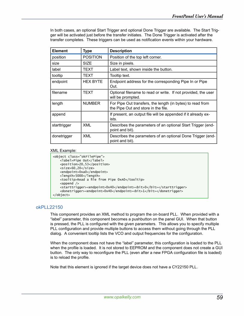
59
FrontPanel User’s Manual
www.opalkelly.com
In both cases, an optional Start Trigger and optional Done Trigger are available. The Start Trig-ger will be activated just before the transfer initiates. The Done Trigger is activated after the transfer completes. These triggers can be used as notification events within your hardware.
Element Type Descriptionposition POSITION Position of the top left corner.size SIZE Size in pixels.label TEXT Label text, shown inside the button.tooltip TEXT Tooltip text.endpoint HEX BYTE Endpoint address for the corresponding Pipe In or Pipe
Out.filename TEXT Optional filename to read or write. If not provided, the user
will be prompted.length NUMBER For Pipe Out transfers, the length (in bytes) to read from
the Pipe Out and store in the file.append If present, an output file will be appended if it already ex-
ists.starttrigger XML Describes the parameters of an optional Start Trigger (end-
point and bit).donetrigger XML Describes the parameters of an optional Done Trigger (end-
point and bit).
XML Example:<object class=”okFilePipe”> <label>Pipe Out</label> <position>20,53</position> <size>60,20</size> <endpoint>0xa0</endpoint> <length>5000</length> <tooltip>Read a file from Pipe 0xA0</tooltip> <append /> <starttrigger><endpoint>0x40</endpoint><bit>0</bit></starttrigger> <donetrigger><endpoint>0x40</endpoint><bit>1</bit></donetrigger></object>
okPLL22150This component provides an XML method to program the on-board PLL. When provided with a “label” parameter, this component becomes a pushbutton on the panel GUI. When that button is pressed, the PLL is configured with the given parameters. This allows you to specify multiple PLL configuration and provide multiple buttons to access them without going through the PLL dialog. A convenient tooltip lists the VCO and output frequencies for the configuration.
When the component does not have the “label” parameter, this configuration is loaded to the PLL when the profile is loaded. It is not stored to EEPROM and the component does not create a GUI button. The only way to reconfigure the PLL (even after a new FPGA configuration file is loaded) is to reload the profile.
Note that this element is ignored if the target device does not have a CY22150 PLL.
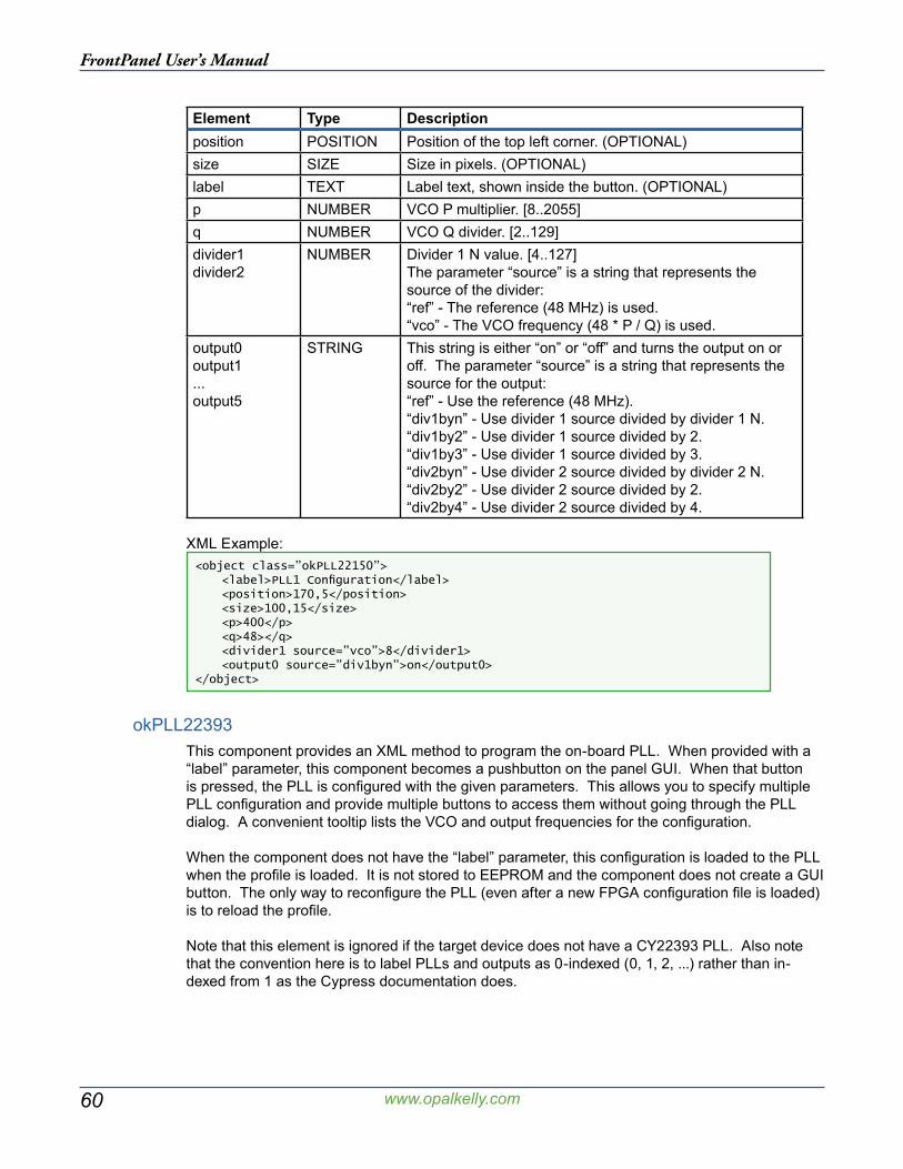
60
FrontPanel User’s Manual
www.opalkelly.com
Element Type Descriptionposition POSITION Position of the top left corner. (OPTIONAL)size SIZE Size in pixels. (OPTIONAL)label TEXT Label text, shown inside the button. (OPTIONAL)p NUMBER VCO P multiplier. [8..2055]q NUMBER VCO Q divider. [2..129]divider1divider2
NUMBER Divider 1 N value. [4..127]The parameter “source” is a string that represents the source of the divider:“ref” - The reference (48 MHz) is used.“vco” - The VCO frequency (48 * P / Q) is used.
output0output1...output5
STRING This string is either “on” or “off” and turns the output on or off. The parameter “source” is a string that represents the source for the output:“ref” - Use the reference (48 MHz).“div1byn” - Use divider 1 source divided by divider 1 N.“div1by2” - Use divider 1 source divided by 2.“div1by3” - Use divider 1 source divided by 3.“div2byn” - Use divider 2 source divided by divider 2 N.“div2by2” - Use divider 2 source divided by 2.“div2by4” - Use divider 2 source divided by 4.
XML Example:<object class=”okPLL22150”> <label>PLL1 Configuration</label> <position>170,5</position> <size>100,15</size> <p>400</p> <q>48></q> <divider1 source=”vco”>8</divider1> <output0 source=”div1byn”>on</output0></object>
okPLL22393This component provides an XML method to program the on-board PLL. When provided with a “label” parameter, this component becomes a pushbutton on the panel GUI. When that button is pressed, the PLL is configured with the given parameters. This allows you to specify multiple PLL configuration and provide multiple buttons to access them without going through the PLL dialog. A convenient tooltip lists the VCO and output frequencies for the configuration.
When the component does not have the “label” parameter, this configuration is loaded to the PLL when the profile is loaded. It is not stored to EEPROM and the component does not create a GUI button. The only way to reconfigure the PLL (even after a new FPGA configuration file is loaded) is to reload the profile.
Note that this element is ignored if the target device does not have a CY22393 PLL. Also note that the convention here is to label PLLs and outputs as 0-indexed (0, 1, 2, ...) rather than in-dexed from 1 as the Cypress documentation does.
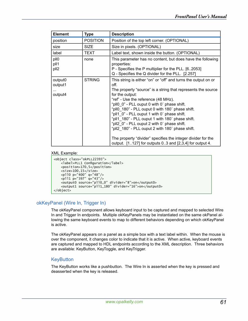
61
FrontPanel User’s Manual
www.opalkelly.com
Element Type Descriptionposition POSITION Position of the top left corner. (OPTIONAL)size SIZE Size in pixels. (OPTIONAL)label TEXT Label text, shown inside the button. (OPTIONAL)pll0pll1pll2
none This parameter has no content, but does have the following properties:P - Specifies the P multiplier for the PLL. [6..2053]Q - Specifies the Q divider for the PLL. [2.257]
output0output1...output4
STRING This string is either “on” or “off” and turns the output on or off.The property “source” is a string that represents the source for the output:“ref” - Use the reference (48 MHz).“pll0_0” - PLL ouput 0 with 0˚ phase shift.“pll0_180” - PLL ouput 0 with 180˚ phase shift.“pll1_0” - PLL ouput 1 with 0˚ phase shift.“pll1_180” - PLL ouput 1 with 180˚ phase shift.“pll2_0” - PLL ouput 2 with 0˚ phase shift.“pll2_180” - PLL ouput 2 with 180˚ phase shift.
The property “divider” specifies the integer divider for the output. [1..127] for outputs 0..3 and [2,3,4] for output 4.
XML Example:<object class=”okPLL22393”> <label>PLL1 Configuration</label> <position>170,5</position> <size>100,15</size> <pll0 p=”400” q=”48”/> <pll1 p=”397” q=”43”/> <output0 source=”pll0_0” divider=”8”>on</output0> <output1 source=”pll1_180” divider=”16”>on</output0></object>
okKeyPanel (Wire In, Trigger In)The okKeyPanel component allows keyboard input to be captured and mapped to selected Wire In and Trigger In endpoints. Multiple okKeyPanels may be instantiated on the same okPanel al-lowing the same keyboard events to map to different behaviors depending on which okKeyPanel is active.
The okKeyPanel appears on a panel as a simple box with a text label within. When the mouse is over the component, it changes color to indicate that it is active. When active, keyboard events are captured and mapped to HDL endpoints according to the XML description. Three behaviors are available: KeyButton, KeyToggle, and KeyTrigger.
KeyButtonThe KeyButton works like a pushbutton. The Wire In is asserted when the key is pressed and deasserted when the key is released.
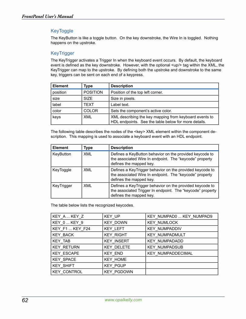
62
FrontPanel User’s Manual
www.opalkelly.com
KeyToggleThe KeyButton is like a toggle button. On the key downstroke, the Wire In is toggled. Nothing happens on the upstroke.
KeyTriggerThe KeyTrigger activates a Trigger In when the keyboard event occurs. By default, the keyboard event is defined as the key downstroke. However, with the optional <up/> tag within the XML, the KeyTrigger can map to the upstroke. By defining both the upstroke and downstroke to the same key, triggers can be sent on each end of a keypress.
Element Type Descriptionposition POSITION Position of the top left corner.size SIZE Size in pixels.label TEXT Label text.color COLOR Sets the component’s active color.keys XML XML describing the key mapping from keyboard events to
HDL endpoints. See the table below for more details.
The following table describes the nodes of the <key> XML element within the component de-scription. This mapping is used to associate a keyboard event with an HDL endpoint.
Element Type DescriptionKeyButton XML Defines a KeyButton behavior on the provided keycode to
the associated Wire In endpoint. The “keycode” property defines the mapped key.
KeyToggle XML Defines a KeyTrigger behavior on the provided keycode to the associated Wire In endpoint. The “keycode” property defines the mapped key.
KeyTrigger XML Defines a KeyTrigger behavior on the provided keycode to the associated Trigger In endpoint. The “keycode” property defines the mapped key.
The table below lists the recognized keycodes.
KEY_A ... KEY_Z KEY_UP KEY_NUMPAD0 ... KEY_NUMPAD9KEY_0 ... KEY_9 KEY_DOWN KEY_NUMLOCKKEY_F1 ... KEY_F24 KEY_LEFT KEY_NUMPADDIVKEY_BACK KEY_RIGHT KEY_NUMPADMULTKEY_TAB KEY_INSERT KEY_NUMPADADDKEY_RETURN KEY_DELETE KEY_NUMPADSUBKEY_ESCAPE KEY_END KEY_NUMPADDECIMALKEY_SPACE KEY_HOMEKEY_SHIFT KEY_PGUPKEY_CONTROL KEY_PGDOWN

63
FrontPanel User’s Manual
www.opalkelly.com
XML Example:<object class=”okKeyPanel”> <label>Key Panel A</label> <color>#b0f0b0</color> <position>5,260</position> <size>100,55</size> <keys> <KeyButton keycode=”KEY_UP”> <endpoint>0x00</endpoint><bit>0</bit> </KeyButton> <KeyToggle keycode=”KEY_DOWN”> <endpoint>0x00</endpoint><bit>1</bit> </KeyButton> <KeyTrigger keycode=”KEY_A”> <endpoint>0x40</endpoint><bit>1</bit> </KeyTrigger> <KeyTrigger keycode=”KEY_A”> <up/> <endpoint>0x40</endpoint><bit>1</bit> </KeyTrigger> </keys></object>

64
FrontPanel User’s Manual
www.opalkelly.com
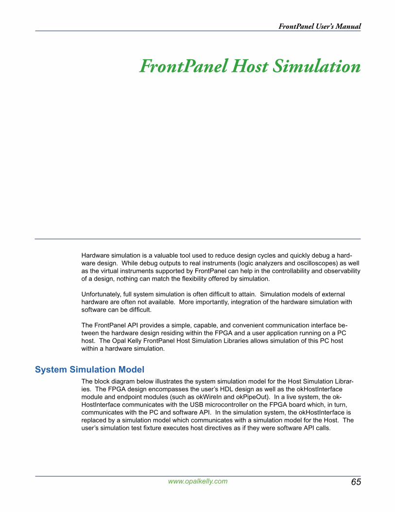
65
FrontPanel User’s Manual
www.opalkelly.com
FrontPanel Host Simulation
Hardware simulation is a valuable tool used to reduce design cycles and quickly debug a hard-ware design. While debug outputs to real instruments (logic analyzers and oscilloscopes) as well as the virtual instruments supported by FrontPanel can help in the controllability and observability of a design, nothing can match the flexibility offered by simulation.
Unfortunately, full system simulation is often difficult to attain. Simulation models of external hardware are often not available. More importantly, integration of the hardware simulation with software can be difficult.
The FrontPanel API provides a simple, capable, and convenient communication interface be-tween the hardware design residing within the FPGA and a user application running on a PC host. The Opal Kelly FrontPanel Host Simulation Libraries allows simulation of this PC host within a hardware simulation.
System Simulation ModelThe block diagram below illustrates the system simulation model for the Host Simulation Librar-ies. The FPGA design encompasses the user’s HDL design as well as the okHostInterface module and endpoint modules (such as okWireIn and okPipeOut). In a live system, the ok-HostInterface communicates with the USB microcontroller on the FPGA board which, in turn, communicates with the PC and software API. In the simulation system, the okHostInterface is replaced by a simulation model which communicates with a simulation model for the Host. The user’s simulation test fixture executes host directives as if they were software API calls.

66
FrontPanel User’s Manual
www.opalkelly.com
okTriggerIn
okWireOut
okHostInterface
User’s HDL
okWireIn
okPipeIn
PC Host
ModelSim Host
Complete FPGA Design
The goal of this type of simulation model is to simulate the complete FPGA design without hav-ing to make changes specific to the simulation model. In reality, many designs will require some modification, but in this case the host can be simulated as realistically as possible.
Simulation RequirementsThe Opal Kelly FrontPanel Host Simulation Library has been precompiled for use with ModelSim XE III 6.1e Starter Edition (the version packaged with the Xilinx ISE tools -- conversion to differ-ent versions of ModelSim can be done using the “refresh” command within ModelSim) as well as Aldec ActiveHDL 7.1 and higher.
Configuring ActiveHDLLaunch ActiveHDL 7.1 and follow the steps below:
1. Launch the Library Manager (View → Library Manager).2. On the top menu, select Library Attach Library.
3. Navigate to the Opal Kelly ActiveHDL simulation library in the FrontPanel installation di-rectory and select the “lib” file to install the library. (okFPsim _ ver is the Verilog library. okFPsim is the VHDL library.)
4. Repeat Step 3 for the other library.
Configuring ModelSimA small change to the ModelSim configuration file (modelsim.ini) will allow you to access the Host Simulation Library from within any project and therefore not have to copy the library to each project’s simulation directory. The configuration file is (by default) located at the following path:
C:\Modeltech_xe_starter\modelsim.ini
Open this file in a text editor. The file is read-only, so you may want to make a copy of the file and edit the copy. Add the following link to the “Verilog Section” (note that this should all be on a single line):
okFPsim_ver = c:/Program Files/Opal Kelly/FrontPanel/FrontPanelHDL/ModelSimXE61e/okFPsim_verokFPsim = c:/Program Files/Opal Kelly/FrontPanel/FrontPanelHDL/ModelSimXE61e/okFPsim
Whenever ModelSim is started, it will include this library and the models should be accessible from your simulation project.

67
FrontPanel User’s Manual
www.opalkelly.com
Adding Host Simulation to a Test FixtureA test fixture which simulates the FrontPanel Host requires the following three components:
1. Instantiation of the device under test (DUT). This is required in any test fixture.
2. A behavioral block which calls the Host Simulation Library to mimic the FrontPanel API.
3. Include okHostCalls.v. This file contains the tasks which simulate the various host API functions.
The last two items are specific to FrontPanel Host Simulation. The table below lists the FrontPanel API calls that are available within the Host Simulation Library. In most cases, the parameters are identical to the corresponding FrontPanel API calls.
SetWireIns GetWireOutValueActivateTriggerIn IsTriggeredWriteToPipeIn ReadFromPipeOutWriteToBlockPipeIn ReadFromBlockPipeOutUpdateWireIns UpdateWireOutsUpdateTriggerOuts FrontPanelReset
Example Test FixturesThe Simulation subdirectory in the FrontPanel installation location contains sample test fixture templates for simulation. They show the general flow and structure of a test fixture that includes the FrontPanel host interface simulation model. These templates should be the starting point for your own simulation test fixtures.
VerilogFor Verilog simulation, dut _ tf.v (your device-under-test test fixture) is used together with okHostCalls.v. The latter includes the necessary code to communicate with the host interface model.
VHDLFor VHDL simulation, a corresponding okHostCalls is not necessary. Instead, these routines are actually included in dut _ tf.vhd. Note that dut _ tf.vhd is significantly longer than dut _ tf.v.
ResetIn a live FPGA design, the FPGA automatically performs a reset of all logic within the fabric after configuration. This assures that the entire design start in a known state which is established by the design.
In a simulation environment, this reset signal is not always simulated and some signals may start in an unknown state. The FrontPanelReset call will reset the host interface functions and as-sure that the simulation starts off in a known state. It is therefore recommended that your simula-tion issue a call Reset at the beginning of the simulation.
Simulating PipesPipe transfer calls utilize global array variables in the test fixture to store the data that will be transmitted or received. These global variables must be declared within the user’s testbench if
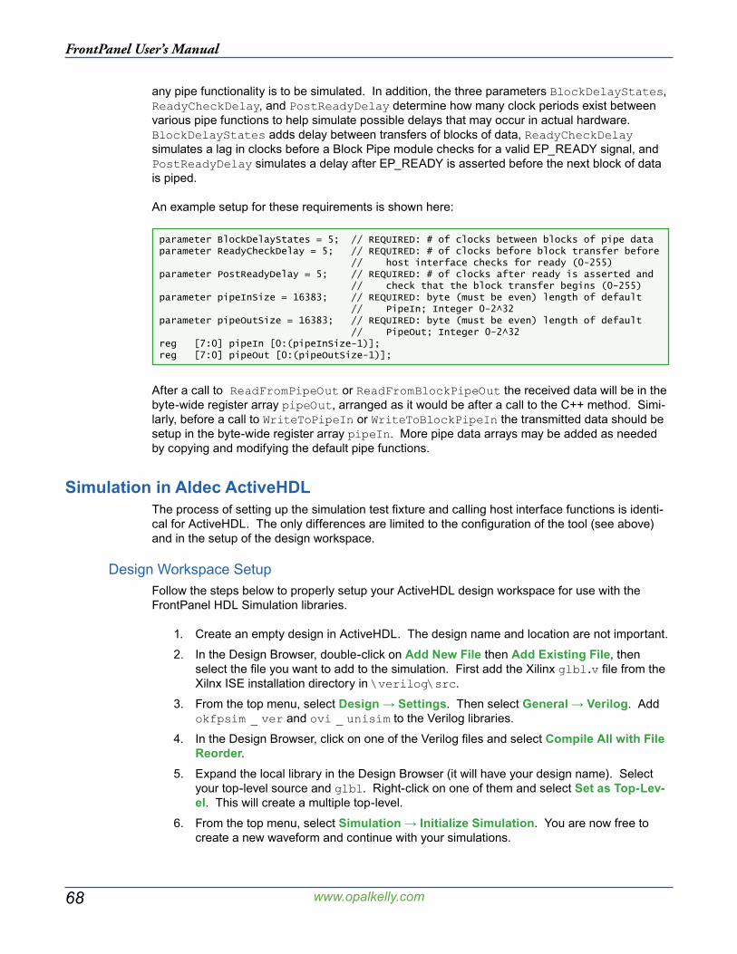
68
FrontPanel User’s Manual
www.opalkelly.com
any pipe functionality is to be simulated. In addition, the three parameters BlockDelayStates, ReadyCheckDelay, and PostReadyDelay determine how many clock periods exist between various pipe functions to help simulate possible delays that may occur in actual hardware. BlockDelayStates adds delay between transfers of blocks of data, ReadyCheckDelay simulates a lag in clocks before a Block Pipe module checks for a valid EP_READY signal, and PostReadyDelay simulates a delay after EP_READY is asserted before the next block of data is piped.
An example setup for these requirements is shown here:
parameter BlockDelayStates = 5; // REQUIRED: # of clocks between blocks of pipe dataparameter ReadyCheckDelay = 5; // REQUIRED: # of clocks before block transfer before // host interface checks for ready (0-255)parameter PostReadyDelay = 5; // REQUIRED: # of clocks after ready is asserted and // check that the block transfer begins (0-255)parameter pipeInSize = 16383; // REQUIRED: byte (must be even) length of default // PipeIn; Integer 0-2^32parameter pipeOutSize = 16383; // REQUIRED: byte (must be even) length of default // PipeOut; Integer 0-2^32reg [7:0] pipeIn [0:(pipeInSize-1)];reg [7:0] pipeOut [0:(pipeOutSize-1)];
After a call to ReadFromPipeOut or ReadFromBlockPipeOut the received data will be in the byte-wide register array pipeOut, arranged as it would be after a call to the C++ method. Simi-larly, before a call to WriteToPipeIn or WriteToBlockPipeIn the transmitted data should be setup in the byte-wide register array pipeIn. More pipe data arrays may be added as needed by copying and modifying the default pipe functions.
Simulation in Aldec ActiveHDLThe process of setting up the simulation test fixture and calling host interface functions is identi-cal for ActiveHDL. The only differences are limited to the configuration of the tool (see above) and in the setup of the design workspace.
Design Workspace SetupFollow the steps below to properly setup your ActiveHDL design workspace for use with the FrontPanel HDL Simulation libraries.
1. Create an empty design in ActiveHDL. The design name and location are not important.
2. In the Design Browser, double-click on Add New File then Add Existing File, then select the file you want to add to the simulation. First add the Xilinx glbl.v file from the Xilnx ISE installation directory in \verilog\src.
3. From the top menu, select Design → Settings. Then select General → Verilog. Add okfpsim _ ver and ovi _ unisim to the Verilog libraries.
4. In the Design Browser, click on one of the Verilog files and select Compile All with File Reorder.
5. Expand the local library in the Design Browser (it will have your design name). Select your top-level source and glbl. Right-click on one of them and select Set as Top-Lev-el. This will create a multiple top-level.
6. From the top menu, select Simulation → Initialize Simulation. You are now free to create a new waveform and continue with your simulations.
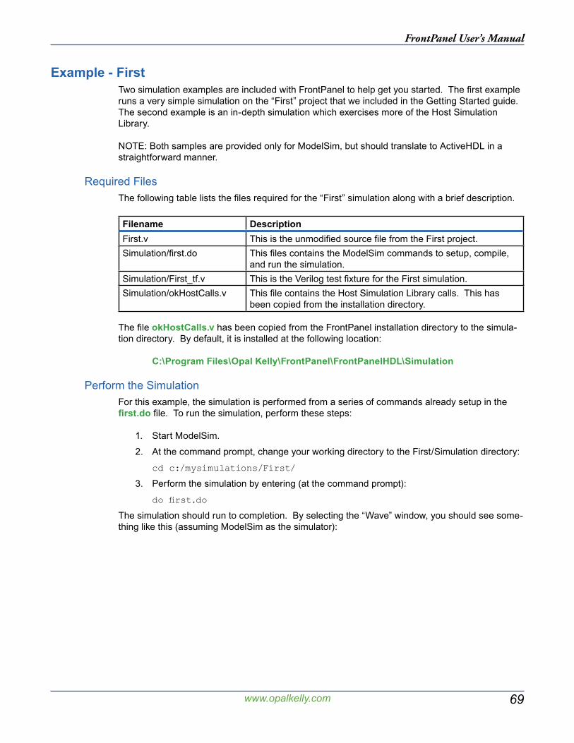
69
FrontPanel User’s Manual
www.opalkelly.com
Example - FirstTwo simulation examples are included with FrontPanel to help get you started. The first example runs a very simple simulation on the “First” project that we included in the Getting Started guide. The second example is an in-depth simulation which exercises more of the Host Simulation Library.
NOTE: Both samples are provided only for ModelSim, but should translate to ActiveHDL in a straightforward manner.
Required FilesThe following table lists the files required for the “First” simulation along with a brief description.
Filename DescriptionFirst.v This is the unmodified source file from the First project.Simulation/first.do This files contains the ModelSim commands to setup, compile,
and run the simulation.Simulation/First_tf.v This is the Verilog test fixture for the First simulation.Simulation/okHostCalls.v This file contains the Host Simulation Library calls. This has
been copied from the installation directory.
The file okHostCalls.v has been copied from the FrontPanel installation directory to the simula-tion directory. By default, it is installed at the following location:
C:\Program Files\Opal Kelly\FrontPanel\FrontPanelHDL\Simulation
Perform the SimulationFor this example, the simulation is performed from a series of commands already setup in the first.do file. To run the simulation, perform these steps:
1. Start ModelSim.
2. At the command prompt, change your working directory to the First/Simulation directory:
cd c:/mysimulations/First/
3. Perform the simulation by entering (at the command prompt):
do first.do
The simulation should run to completion. By selecting the “Wave” window, you should see some-thing like this (assuming ModelSim as the simulator):
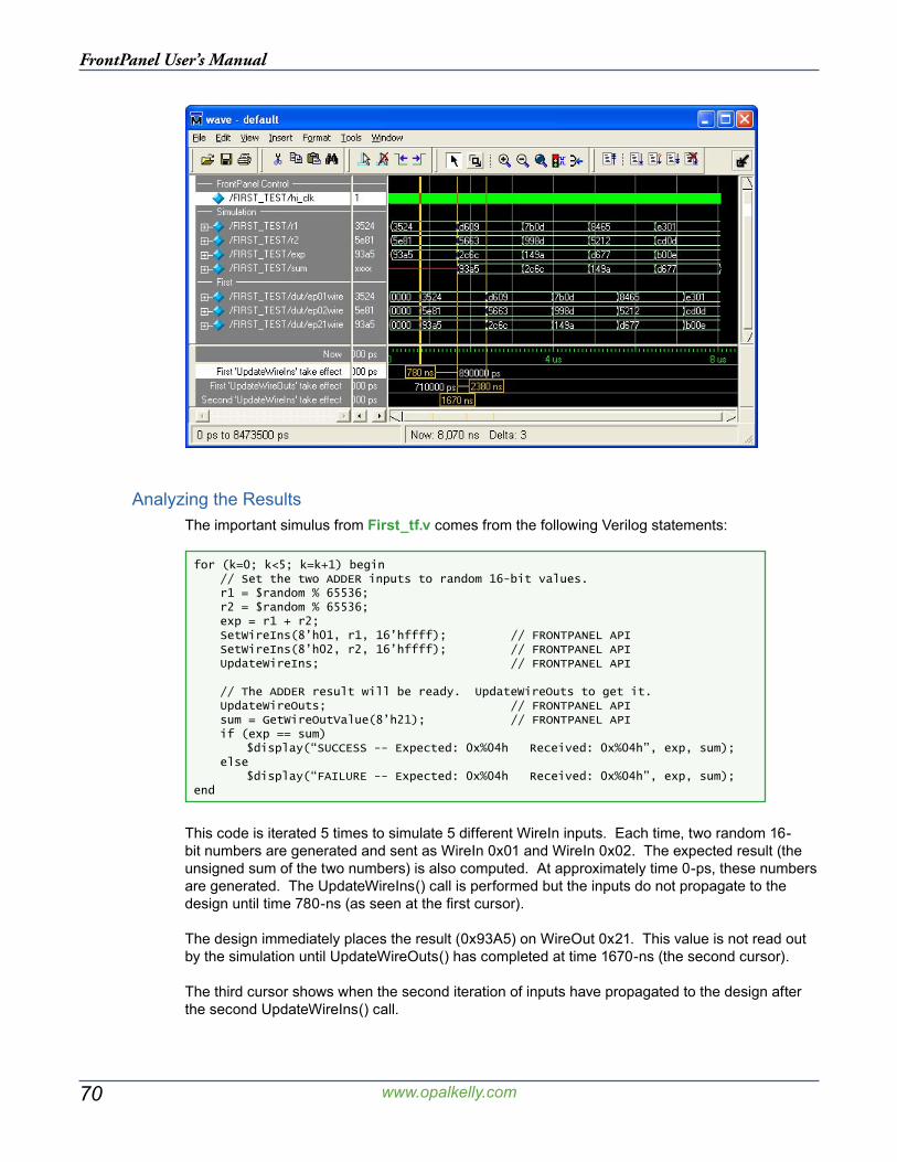
70
FrontPanel User’s Manual
www.opalkelly.com
Analyzing the ResultsThe important simulus from First_tf.v comes from the following Verilog statements:
for (k=0; k<5; k=k+1) begin // Set the two ADDER inputs to random 16-bit values. r1 = $random % 65536; r2 = $random % 65536; exp = r1 + r2; SetWireIns(8’h01, r1, 16’hffff); // FRONTPANEL API SetWireIns(8’h02, r2, 16’hffff); // FRONTPANEL API UpdateWireIns; // FRONTPANEL API // The ADDER result will be ready. UpdateWireOuts to get it. UpdateWireOuts; // FRONTPANEL API sum = GetWireOutValue(8’h21); // FRONTPANEL API if (exp == sum) $display(“SUCCESS -- Expected: 0x%04h Received: 0x%04h”, exp, sum); else $display(“FAILURE -- Expected: 0x%04h Received: 0x%04h”, exp, sum);end
This code is iterated 5 times to simulate 5 different WireIn inputs. Each time, two random 16-bit numbers are generated and sent as WireIn 0x01 and WireIn 0x02. The expected result (the unsigned sum of the two numbers) is also computed. At approximately time 0-ps, these numbers are generated. The UpdateWireIns() call is performed but the inputs do not propagate to the design until time 780-ns (as seen at the first cursor).
The design immediately places the result (0x93A5) on WireOut 0x21. This value is not read out by the simulation until UpdateWireOuts() has completed at time 1670-ns (the second cursor).
The third cursor shows when the second iteration of inputs have propagated to the design after the second UpdateWireIns() call.
71
FrontPanel User’s Manual
www.opalkelly.com
Simulation AccuracyBack-to-back wire updates such as the ones seen in this simulation do not, in fact occur this quickly. The bandwidth constraints on USB and other operating system issues will cause them to happen much slower. In the interest of simulation speed, however, we have accelerated the response time of some of the host simulation actions. The user may, at his or her discretion, place additional delays within the simulation in order to better model the speed of the real host interface. In most cases, this will not be necessary
Example - DES TesterA more thorough example of the capabilities of the Host Simulation Library, including PipeIn and PipeOut transfers, is included with the DES sample. A step-by-step review of the setup and ex-ecution of this sample has been included in Part IV of our online FrontPanel tutorial.

72
FrontPanel User’s Manual
www.opalkelly.com
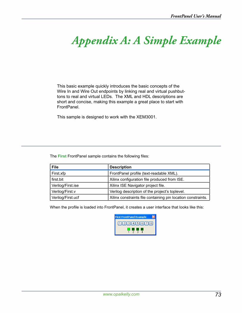
73
FrontPanel User’s Manual
www.opalkelly.com
Appendix A: A Simple Example
This basic example quickly introduces the basic concepts of the Wire In and Wire Out endpoints by linking real and virtual pushbut-tons to real and virtual LEDs. The XML and HDL descriptions are short and concise, making this example a great place to start with FrontPanel.
This sample is designed to work with the XEM3001.
The First FrontPanel sample contains the following files:
File DescriptionFirst.xfp FrontPanel profile (text-readable XML).first.bit Xilinx configuration file produced from ISE.Verilog/First.ise Xilinx ISE Navigator project file.Verilog/First.v Verilog description of the project’s toplevel.Verilog/First.ucf Xilinx constraints file containing pin location constraints.
When the profile is loaded into FrontPanel, it creates a user interface that looks like this:
74
FrontPanel User’s Manual
www.opalkelly.com
Toplevel DescriptionThe file First.v contains the Verilog description of the project, including all pins which are physi-cally connected to the FPGA. It’s entire contents are listed below:
module toplevel( input wire [7:0] hi_in, input wire [1:0] hi_out, inout wire [15:0] hi_inout, output wire [7:0] led, input wire [3:0] button );
// Target interface bus:wire ti_clk;wire [30:0] ok1;wire [16:0] ok2;
// Endpoint connections:wire [15:0] ep00wire;wire [15:0] ep20wire;
assign led = ~ep00wire;assign ep20wire = {12’b0000, ~button};
// Instantiate the okHostInterface and connect endpoints to// the target interface.okHostInterface okHI( .hi_in(hi_in), .hi_out(hi_out), .hi_inout(hi_inout), .ti_clk(ti_clk), .ok1(ok1), .ok2(ok2) );
okWireIn ep00 ( .ok1(ok1), .ok2(ok2), .ep_addr(8’h00), .ep_dataout(ep00wire));
okWireOut ep20 ( .ok1(ok1), .ok2(ok2), .ep_addr(8’h20), .ep_datain(ep20wire));
endmodule
Listed inside the module definition are several wires. Most of these are for the FrontPanel host interface. The two other busses, LED[7:0] and BUTTON[3:0] connect to the LEDs and pushbut-tons on the XEM3001. Their specific pin locations are constrained in First.ucf.
Target LogicThe logic description for this example is very simple and only consists of two lines of HDL con-necting the Wire In endpoint to the physical LEDs and the Wire Out endpoint to the physical pushbuttons:
assign led = ~ep00wire;assign ep20wire = {12’b0000, ~button};
The LEDs are attached to endpoint 0x00 and the pushbuttons are attached to endpoint 0x20.
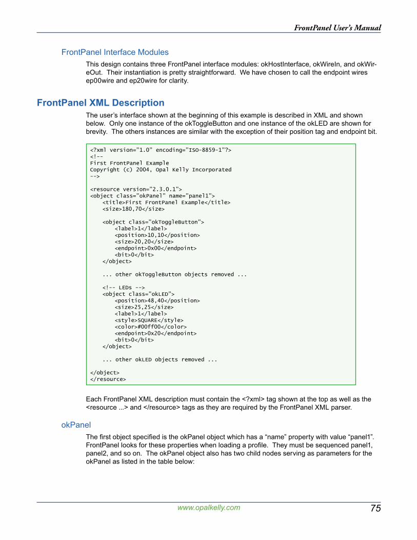
75
FrontPanel User’s Manual
www.opalkelly.com
FrontPanel Interface ModulesThis design contains three FrontPanel interface modules: okHostInterface, okWireIn, and okWir-eOut. Their instantiation is pretty straightforward. We have chosen to call the endpoint wires ep00wire and ep20wire for clarity.
FrontPanel XML DescriptionThe user’s interface shown at the beginning of this example is described in XML and shown below. Only one instance of the okToggleButton and one instance of the okLED are shown for brevity. The others instances are similar with the exception of their position tag and endpoint bit.
<?xml version=”1.0” encoding=”ISO-8859-1”?><!--First FrontPanel ExampleCopyright (c) 2004, Opal Kelly Incorporated-->
<resource version=”2.3.0.1”><object class=”okPanel” name=”panel1”> <title>First FrontPanel Example</title> <size>180,70</size>
<object class=”okToggleButton”> <label>1</label> <position>10,10</position> <size>20,20</size> <endpoint>0x00</endpoint> <bit>0</bit> </object>
... other okToggleButton objects removed ...
<!-- LEDs --> <object class=”okLED”> <position>48,40</position> <size>25,25</size> <label>1</label> <style>SQUARE</style> <color>#00ff00</color> <endpoint>0x20</endpoint> <bit>0</bit> </object>
... other okLED objects removed ...
</object></resource>
Each FrontPanel XML description must contain the <?xml> tag shown at the top as well as the <resource ...> and </resource> tags as they are required by the FrontPanel XML parser.
okPanelThe first object specified is the okPanel object which has a “name” property with value “panel1”. FrontPanel looks for these properties when loading a profile. They must be sequenced panel1, panel2, and so on. The okPanel object also has two child nodes serving as parameters for the okPanel as listed in the table below:
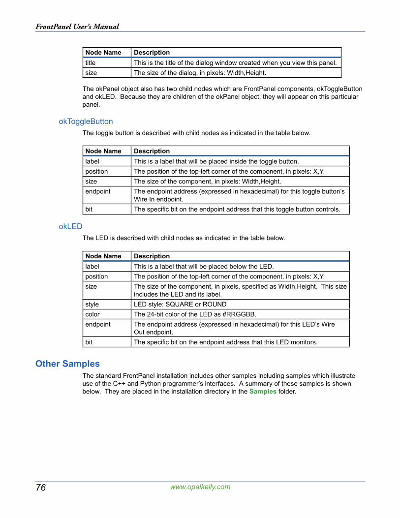
76
FrontPanel User’s Manual
www.opalkelly.com
Node Name Descriptiontitle This is the title of the dialog window created when you view this panel.size The size of the dialog, in pixels: Width,Height.
The okPanel object also has two child nodes which are FrontPanel components, okToggleButton and okLED. Because they are children of the okPanel object, they will appear on this particular panel.
okToggleButtonThe toggle button is described with child nodes as indicated in the table below.
Node Name Descriptionlabel This is a label that will be placed inside the toggle button.position The position of the top-left corner of the component, in pixels: X,Y.size The size of the component, in pixels: Width,Height.endpoint The endpoint address (expressed in hexadecimal) for this toggle button’s
Wire In endpoint.bit The specific bit on the endpoint address that this toggle button controls.
okLEDThe LED is described with child nodes as indicated in the table below.
Node Name Descriptionlabel This is a label that will be placed below the LED.position The position of the top-left corner of the component, in pixels: X,Y.size The size of the component, in pixels, specified as Width,Height. This size
includes the LED and its label.style LED style: SQUARE or ROUNDcolor The 24-bit color of the LED as #RRGGBB.endpoint The endpoint address (expressed in hexadecimal) for this LED’s Wire
Out endpoint.bit The specific bit on the endpoint address that this LED monitors.
Other SamplesThe standard FrontPanel installation includes other samples including samples which illustrate use of the C++ and Python programmer’s interfaces. A summary of these samples is shown below. They are placed in the installation directory in the Samples folder.
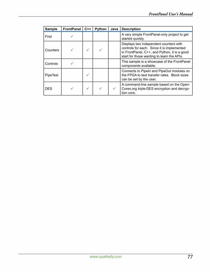
77
FrontPanel User’s Manual
www.opalkelly.com
Sample FrontPanel C++ Python Java Description
First A very simple FrontPanel-only project to get started quickly.
Counters
Displays two independent counters with controls for each. Since it is implemented in FrontPanel, C++, and Python, it is a good start for those wanting to learn the APIs.
Controls This sample is a showcase of the FrontPanel components available.
PipeTest Connects to PipeIn and PipeOut modules on the FPGA to test transfer rates. Block sizes can be set by the user.
DES A command-line sample based on the Open-Cores.org triple-DES encryption and decryp-tion core.

78
FrontPanel User’s Manual
www.opalkelly.com
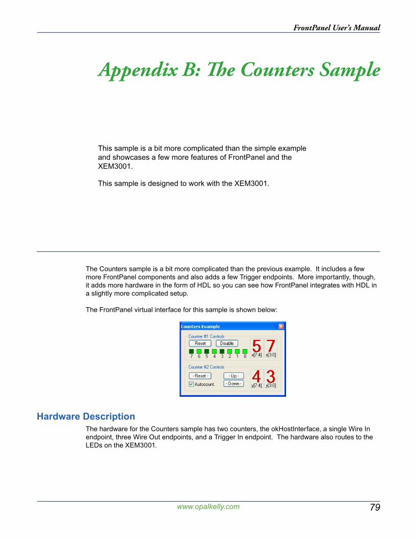
79
FrontPanel User’s Manual
www.opalkelly.com
Appendix B: The Counters Sample
This sample is a bit more complicated than the simple example and showcases a few more features of FrontPanel and the XEM3001.
This sample is designed to work with the XEM3001.
The Counters sample is a bit more complicated than the previous example. It includes a few more FrontPanel components and also adds a few Trigger endpoints. More importantly, though, it adds more hardware in the form of HDL so you can see how FrontPanel integrates with HDL in a slightly more complicated setup.
The FrontPanel virtual interface for this sample is shown below:
Hardware DescriptionThe hardware for the Counters sample has two counters, the okHostInterface, a single Wire In endpoint, three Wire Out endpoints, and a Trigger In endpoint. The hardware also routes to the LEDs on the XEM3001.
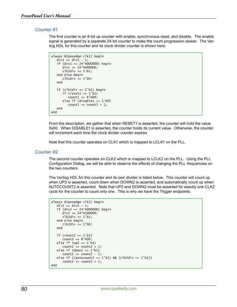
80
FrontPanel User’s Manual
www.opalkelly.com
Counter #1The first counter is an 8-bit up counter with enable, synchronous reset, and disable. The enable signal is generated by a separate 24-bit counter to make the count progression slower. The Ver-ilog HDL for this counter and its clock divider counter is shown here:
always @(posedge clk1) begin div1 <= div1 - 1; if (div1 == 24’h000000) begin div1 <= 24’h400000; clk1div <= 1’b1; end else begin clk1div <= 1’b0; end if (clk1div == 1’b1) begin if (reset1 == 1’b1) count1 <= 8’h00; else if (disable1 == 1’b0) count1 <= count1 + 1; endend
From the description, we gather that when RESET1 is asserted, the counter will hold the value 0x00. When DISABLE1 is asserted, the counter holds its current value. Otherwise, the counter will increment each time the clock divider counter expires.
Note that this counter operates on CLK1 which is mapped to LCLK1 on the PLL.
Counter #2The second counter operates on CLK2 which is mapped to LCLK2 on the PLL. Using the PLL Configuration Dialog, we will be able to observe the effects of changing the PLL frequencies on the two counters.
The Verilog HDL for this counter and its own divider is listed below. This counter will count up when UP2 is asserted, count down when DOWN2 is asserted, and automatically count up when AUTOCOUNT2 is asserted. Note that UP2 and DOWN2 must be asserted for exactly one CLK2 cycle for the counter to count only one. This is why we have the Trigger endpoints.
always @(posedge clk2) begin div2 <= div2 - 1; if (div2 == 24’h000000) begin div2 <= 24’h100000; clk2div <= 1’b1; end else begin clk2div <= 1’b0; end if (reset2 == 1’b1) count2 <= 8’h00; else if (up2 == 1’b1) count2 <= count2 + 1; else if (down2 == 1’b1) count2 <= count2 - 1; else if ((autocount2 == 1’b1) && (clk2div == 1’b1)) count2 <= count2 + 1;end
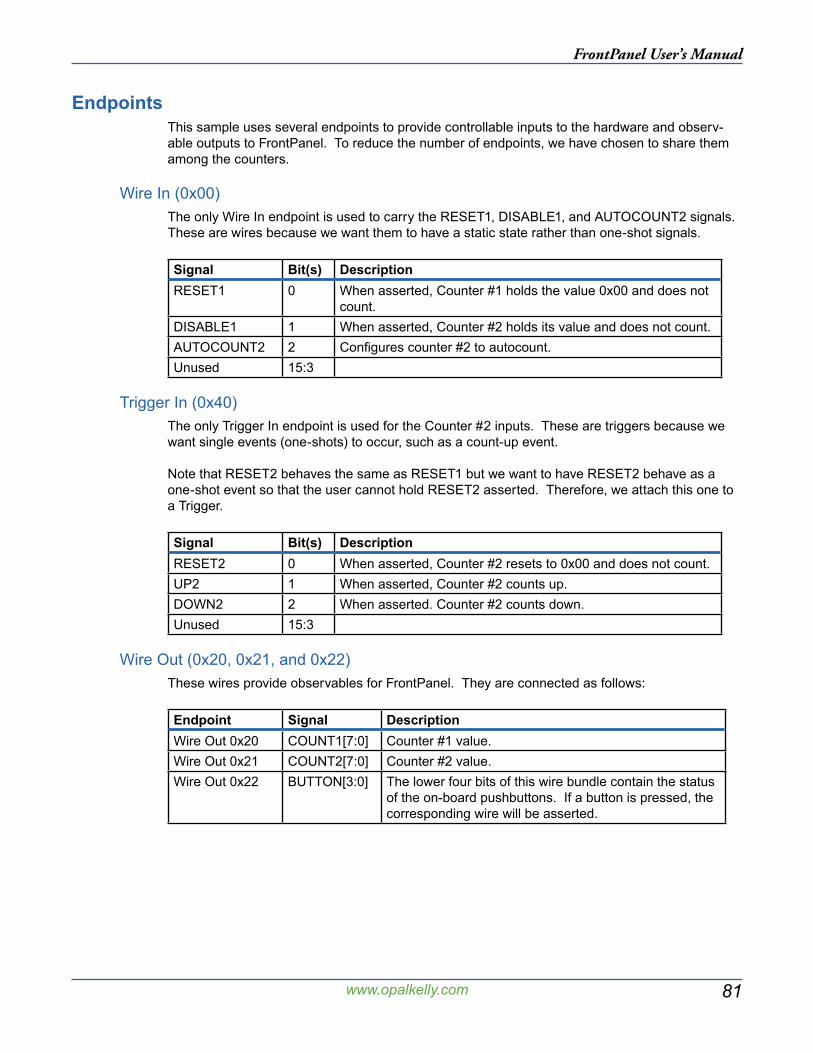
81
FrontPanel User’s Manual
www.opalkelly.com
EndpointsThis sample uses several endpoints to provide controllable inputs to the hardware and observ-able outputs to FrontPanel. To reduce the number of endpoints, we have chosen to share them among the counters.
Wire In (0x00)The only Wire In endpoint is used to carry the RESET1, DISABLE1, and AUTOCOUNT2 signals. These are wires because we want them to have a static state rather than one-shot signals.
Signal Bit(s) DescriptionRESET1 0 When asserted, Counter #1 holds the value 0x00 and does not
count.DISABLE1 1 When asserted, Counter #2 holds its value and does not count.AUTOCOUNT2 2 Configures counter #2 to autocount.Unused 15:3
Trigger In (0x40)The only Trigger In endpoint is used for the Counter #2 inputs. These are triggers because we want single events (one-shots) to occur, such as a count-up event.
Note that RESET2 behaves the same as RESET1 but we want to have RESET2 behave as a one-shot event so that the user cannot hold RESET2 asserted. Therefore, we attach this one to a Trigger.
Signal Bit(s) DescriptionRESET2 0 When asserted, Counter #2 resets to 0x00 and does not count.UP2 1 When asserted, Counter #2 counts up.DOWN2 2 When asserted. Counter #2 counts down.Unused 15:3
Wire Out (0x20, 0x21, and 0x22)These wires provide observables for FrontPanel. They are connected as follows:
Endpoint Signal DescriptionWire Out 0x20 COUNT1[7:0] Counter #1 value.Wire Out 0x21 COUNT2[7:0] Counter #2 value.Wire Out 0x22 BUTTON[3:0] The lower four bits of this wire bundle contain the status
of the on-board pushbuttons. If a button is pressed, the corresponding wire will be asserted.

82
FrontPanel User’s Manual
www.opalkelly.com
FrontPanel ComponentsThe user interface for the Counters sample includes two panels. The first panel contains five but-tons, four hex displays, eight LEDs, and a check box. There are also two cosmetic components called okStaticBox which are used to group the components visually. The second panel simply contains four LEDs used to display the state of the pushbuttons.
Panel 1: Counters ExampleThe active FrontPanel components are listed below with their corresponding endpoints:
Component Label Endpoint BitokPushbutton Reset 0x00 0okPushbutton Disable 0x00 1okTriggerButton - Reset - 0x40 0okTriggerButton - Up - 0x40 1okTriggerButton - Down - 0x40 2okToggleCheck Autocount. 0x00 2okHex x[7:4] 0x20 4okHex x[3:0] 0x20 0okHex y[7:4] 0x21 4okHex y[3:0] 0x21 0okLED 7 0x20 7okLED 6...1 0x20 6...1okLED 0 0x20 0
Note that the okLED and two of the okHex components share endpoint 0x20. FrontPanel allows this and will update both components when Wire Out endpoints change. It is also possible to map two components to input endpoints.
Panel 2: PushbuttonsThe second panel is not automatically opened when the Conters XFP file is loaded. You can open it by pressing the number `2’ on your keyboard or navigating to
View → Pushbuttons
at the top of the FrontPanel window. This displays a small window with the following compo-nents:
Component Label Endpoint Bit/MaskokLED 3 0x22 3okLED 2 0x22 2okLED 1 0x22 1okLED 0 0x22 0
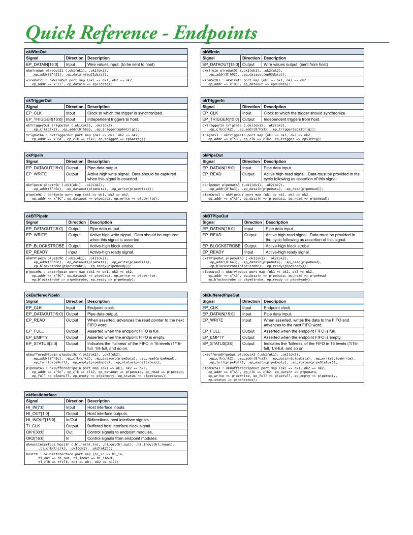
Quick Reference - Endpoints
okPipeInSignal Direction DescriptionEP_DATAOUT[15:0] Output Pipe data output.EP_WRITE Output Active high write signal. Data should be captured
when this signal is asserted.okPipeIn pipeIn9C (.ok1(ok1), .ok2(ok2), .ep_addr(8’h9c), .ep_dataout(pipeData), .ep_write(pipeWrite));
pipeIn9C : okPipeIn port map (ok1 => ok1, ok2 => ok2, ep_addr => x”9C”, ep_dataout => pipeData, ep_write => pipeWrite);
okBufferedPipeInSignal Direction DescriptionEP_CLK Input Endpoint clock.EP_DATAOUT[15:0] Output Pipe data output.EP_READ Output When asserted, advances the read pointer to the next
FIFO word.EP_FULL Output Asserted when the endpoint FIFO is full.EP_EMPTY Output Asserted when the endpoint FIFO is empty.EP_STATUS[3:0] Output Indicates the ‘fullness’ of the FIFO in 16 levels (1/16-
full, 1/8-full, and so on.okBufferedPipeIn pipeOut9C (.ok1(ok1), .ok2(ok2), .ep_addr(8’h9c), .ep_clk(clk2), .ep_dataout(pipeData), .ep_read(pipeRead), .ep_full(pipeFull), .ep_empty(pipeEmpty), .ep_status(pipeStatus));
pipeOutA3 : okBufferedPipeIn port map (ok1 => ok1, ok2 => ok2, ep_addr => x”9c”, ep_clk => clk2, ep_dataout => pipeData, ep_read => pipeRead, ep_full => pipeFull, ep_empty => pipeEmpty, ep_status => pipeStatus);
okWireOutSignal Direction DescriptionEP_DATAIN[15:0] Input Wire values input. (to be sent to host)okWireOut wireOut21 (.ok1(ok1), .ok2(ok2), .ep_addr(8’h21), .ep_datain(ep21data));
wireOut21 : okWireOut port map (ok1 => ok1, ok2 => ok2, ep_addr => x”21”, ep_datain => ep21data);
okPipeOutSignal Direction DescriptionEP_DATAIN[15:0] Input Pipe data input.EP_READ Output Active high read signal. Data must be provided in the
cycle following as assertion of this signal.okPipeOut pipeOutA3 (.ok1(ok1), .ok2(ok2), .ep_addr(8’ha3), .ep_datain(pipeData), .ep_read(pipeRead));
pipeOutA3 : okPipeOut port map (ok1 => ok1, ok2 => ok2, ep_addr => x”A3”, ep_datain => pipeData, ep_read => pipeRead);
okBufferedPipeOutSignal Direction DescriptionEP_CLK Input Endpoint clock.EP_DATAIN[15:0] Input Pipe data input.EP_WRITE Input When asserted, writes the data to the FIFO and
advances to the next FIFO word.EP_FULL Output Asserted when the endpoint FIFO is full.EP_EMPTY Output Asserted when the endpoint FIFO is empty.EP_STATUS[3:0] Output Indicates the ‘fullness’ of the FIFO in 16 levels (1/16-
full, 1/8-full, and so on.okBufferedPipeOut pipeOutA3 (.ok1(ok1), .ok2(ok2), .ep_clk(clk2), .ep_addr(8’ha3), .ep_datain(pipeData), .ep_write(pipeWrite), .ep_full(pipeFull), .ep_empty(pipeEmpty), .ep_status(pipeStatus));
pipeOutA3 : okBufferedPipeOut port map (ok1 => ok1, ok2 => ok2, ep_addr => x”A3”, ep_clk => clk2, ep_datain => pipeData, ep_write => pipeWrite, ep_full => pipeFull, ep_empty => pipeEmpty, ep_status => pipeStatus);
okWireInSignal Direction DescriptionEP_DATAOUT[15:0] Output Wire values output. (sent from host)okWireIn wireOut03 (.ok1(ok1), .ok2(ok2), .ep_addr(8’h03), .ep_dataout(ep03data));
wireOut03 : okWireIn port map (ok1 => ok1, ok2 => ok2, ep_addr => x”03”, ep_dataout => ep03data);
okTriggerOutSignal Direction DescriptionEP_CLK Input Clock to which the trigger is synchronized.EP_TRIGGER[15:0] Input Independent triggers to host.okTriggerOut trigOut6A (.ok1(ok1), .ok2(ok2), .ep_clk(clk2), .ep_addr(8’h6a), .ep_trigger(ep6Atrig));
trigOut6A : okTriggerOut port map (ok1 => ok1, ok2 => ok2, ep_addr => x”6a”, ep_clk => clk2, ep_trigger => ep6Atrig);
okTriggerInSignal Direction DescriptionEP_CLK Input Clock to which the trigger should synchronize.EP_TRIGGER[15:0] Output Independent triggers from host.okTriggerIn trigIn53 (.ok1(ok1), .ok2(ok2), .ep_clk(clk2), .ep_addr(8’h53), .ep_trigger(ep53trig));
trigIn53 : okTriggerIn port map (ok1 => ok1, ok2 => ok2, ep_addr => x”53”, ep_clk => clk2, ep_trigger => ep53trig);
okHostInterfaceSignal Direction DescriptionHI_IN[7:0] Input Host interface inputs.HI_OUT[1:0] Output Host interface outputs.HI_INOUT[15:0] In/Out Bidirectional host interface signals.TI_CLK Output Buffered host interface clock signal.OK1[30:0] Out Control signals to endpoint modules.OK2[16:0] In Control signals from endpoint modules.okHostInterface hostIF (.hi_in(hi_in), .hi_out(hi_out), .hi_inout(hi_inout), .ti_clk(ticlk), .ok1(ok1), .ok2(ok2));
hostIF : okHostInterface port map (hi_in => hi_in, hi_out => hi_out, hi_inout => hi_inout, ti_clk => ticlk, ok1 => ok1, ok2 => ok2);
okBTPipeInSignal Direction DescriptionEP_DATAOUT[15:0] Output Pipe data output.EP_WRITE Output Active high write signal. Data should be captured
when this signal is asserted.EP_BLOCKSTROBE Output Active-high block strobe.EP_READY Input Active-high ready signal.okBTPipeIn pipeIn9C (.ok1(ok1), .ok2(ok2), .ep_addr(8’h9c), .ep_dataout(pipeData), .ep_write(pipeWrite), .ep_blockstrobe(pipeStrobe), .ep_ready(pipeReady));
pipeIn9C : okBTPipeIn port map (ok1 => ok1, ok2 => ok2, ep_addr => x”9C”, ep_dataout => pipeData, ep_write => pipeWrite, ep_blockstrobe => pipeStrobe, ep_ready => pipeReady);
okBTPipeOutSignal Direction DescriptionEP_DATAIN[15:0] Input Pipe data input.EP_READ Output Active high read signal. Data must be provided in
the cycle following as assertion of this signal.EP_BLOCKSTROBE Output Active-high block strobe.EP_READY Input Active-high ready signal.okBTPipeOut pipeOutA3 (.ok1(ok1), .ok2(ok2), .ep_addr(8’ha3), .ep_datain(pipeData), .ep_read(pipeRead), .ep_blockstrobe(pipeStrobe), .ep_ready(pipeReady));
pipeOutA3 : okBTPipeOut port map (ok1 => ok1, ok2 => ok2, ep_addr => x”A3”, ep_datain => pipeData, ep_read => pipeRead ep_blockstrobe => pipeStrobe, ep_ready => pipeReady);
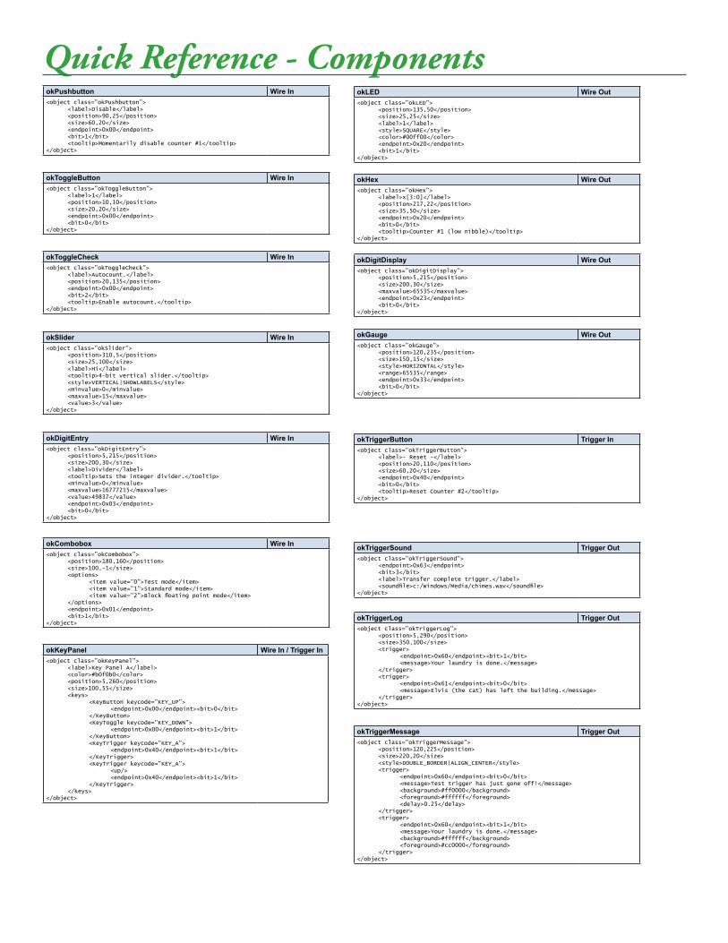
Quick Reference - ComponentsokPushbutton Wire In<object class=”okPushbutton”> <label>Disable</label> <position>90,25</position> <size>60,20</size> <endpoint>0x00</endpoint> <bit>1</bit> <tooltip>Momentarily disable counter #1</tooltip></object>
okToggleButton Wire In<object class=”okToggleButton”> <label>1</label> <position>10,10</position> <size>20,20</size> <endpoint>0x00</endpoint> <bit>0</bit></object>
okToggleCheck Wire In<object class=”okToggleCheck”> <label>Autocount.</label> <position>20,135</position> <endpoint>0x00</endpoint> <bit>2</bit> <tooltip>Enable autocount.</tooltip></object>
okDigitEntry Wire In<object class=”okDigitEntry”> <position>5,215</position> <size>200,30</size> <label>Divider</label> <tooltip>Sets the integer divider.</tooltip> <minvalue>0</minvalue> <maxvalue>16777215</maxvalue> <value>49837</value> <endpoint>0x03</endpoint> <bit>0</bit></object>
okSlider Wire In<object class=”okSlider”> <position>310,5</position> <size>25,100</size> <label>Hi</label> <tooltip>4-bit vertical slider.</tooltip> <style>VERTICAL|SHOWLABELS</style> <minvalue>0</minvalue> <maxvalue>15</maxvalue> <value>3</value></object>
okLED Wire Out<object class=”okLED”> <position>135,50</position> <size>25,25</size> <label>1</label> <style>SQUARE</style> <color>#00ff00</color> <endpoint>0x20</endpoint> <bit>1</bit></object>
okHex Wire Out<object class=”okHex”> <label>x[3:0]</label> <position>217,22</position> <size>35,50</size> <endpoint>0x20</endpoint> <bit>0</bit> <tooltip>Counter #1 (low nibble)</tooltip></object>
okTriggerButton Trigger In<object class=”okTriggerButton”> <label>- Reset -</label> <position>20,110</position> <size>60,20</size> <endpoint>0x40</endpoint> <bit>0</bit> <tooltip>Reset Counter #2</tooltip></object>
okTriggerSound Trigger Out<object class=”okTriggerSound”> <endpoint>0x63</endpoint> <bit>3</bit> <label>Transfer complete trigger.</label> <soundfile>c:/Windows/Media/chimes.wav</soundfile></object>
okDigitDisplay Wire Out<object class=”okDigitDisplay”> <position>5,215</position> <size>200,30</size> <maxvalue>65535</maxvalue> <endpoint>0x23</endpoint> <bit>0</bit></object>
okCombobox Wire In<object class=”okCombobox”> <position>180,160</position> <size>100,-1</size> <options> <item value=”0”>Test mode</item> <item value=”1”>Standard mode</item> <item value=”2”>Block floating point mode</item> </options> <endpoint>0x01</endpoint> <bit>1</bit></object>
okKeyPanel Wire In / Trigger In<object class=”okKeyPanel”> <label>Key Panel A</label> <color>#b0f0b0</color> <position>5,260</position> <size>100,55</size> <keys> <KeyButton keycode=”KEY_UP”> <endpoint>0x00</endpoint><bit>0</bit> </KeyButton> <KeyToggle keycode=”KEY_DOWN”> <endpoint>0x00</endpoint><bit>1</bit> </KeyButton> <KeyTrigger keycode=”KEY_A”> <endpoint>0x40</endpoint><bit>1</bit> </KeyTrigger> <KeyTrigger keycode=”KEY_A”> <up/> <endpoint>0x40</endpoint><bit>1</bit> </KeyTrigger> </keys></object>
okGauge Wire Out<object class=”okGauge”> <position>120,235</position> <size>150,15</size> <style>HORIZONTAL</style> <range>65535</range> <endpoint>0x33</endpoint> <bit>0</bit></object>
okTriggerLog Trigger Out<object class=”okTriggerLog”> <position>5,290</position> <size>350,100</size> <trigger> <endpoint>0x60</endpoint><bit>1</bit> <message>Your laundry is done.</message> </trigger> <trigger> <endpoint>0x61</endpoint><bit>0</bit> <message>Elvis (the cat) has left the building.</message> </trigger></object>
okTriggerMessage Trigger Out<object class=”okTriggerMessage”> <position>120,225</position> <size>220,20</size> <style>DOUBLE_BORDER|ALIGN_CENTER</style> <trigger> <endpoint>0x60</endpoint><bit>0</bit> <message>Test trigger has just gone off!</message> <background>#ff0000</background> <foreground>#ffffff</foreground> <delay>0.25</delay> </trigger> <trigger> <endpoint>0x60</endpoint><bit>1</bit> <message>Your laundry is done.</message> <background>#ffffff</background> <foreground>#cc0000</foreground> </trigger></object>