Embed Size (px)
Citation preview

1
Surgical Technique

2
TELLURIDE 2 MIS SPINAL FIXATION SYSTEM The Telluride 2 MIS Spinal Fixation System is a simple, robust and versatile minimally invasive pedicle screw system consisting of implants and instruments to provide vertebral stabilization of spinal segments in the thoracic, lumbar and sacral regions. The system features:
Cannulated polyaxial pedicle screws
Titanium rods
Surgeon designed instrumentation
Uses either a Percutaneous or Mini-open approach with a series of small, posterior incisions
The system provides:
Reduced muscle trauma & pain
Shorter hospital stays
Faster return to normal activities

3
TELLURIDE 2 MIS SPINAL FIXATION SYSTEM

4
PREOPERATIVE PREPARATION Review and inspect all instrumentation and implants prior to sterilization.
Replace or add any needed components for the planned surgery.
Surgeon must be fully experienced with the required posterior, non-cervical (T1-S2/Ilium) instrumentation techniques.
Read the Telluride 2 Instructions for Use (IFU) for a complete list of prescribing information.
SURGICAL EXPOSURE AND SITE PREPARATION Patient is positioned prone on a radiolucent table and draped in the usual manner.
With fluoroscopy and preoperative imaging, determine the location of the incision, typically 3-4.5 cm from the midline.
The Telluride 2 system is designed for minimally invasive techniques where small incisions are utilized. This system may be used to perform MIS Percutaneous or standard mini-open techniques.
For Percutaneous Techniques: Utilizing a percutaneous approach, make an appropriate skin incision. Finger dissect between the multifidus and longissimus. Palpate to the facet joint, lamina and base of the spinous process to identify the pedicle. Repeat steps for each pedicle where a screw is to be placed.
For Mini-open Techniques: Using a paramedian approach (“Wiltse” -like approach), make an appropriate skin and fascia incision to establish a muscle plane path to locate the pedicles perform blunt dissection of the muscle planes down to the facet joints.

5
TARGETING NEEDLE AND GUIDE WIRE PLACEMENT
Using fluoroscopy, insert the targeting needle to the level of the pedicle through the dissected muscle plane. Confirm the targeting needle is safely placed and has the correct trajectory using a combination of AP and Lateral fluoroscopy, or by orienting fluoroscopy in the plane of the pedicle. Note: This must be done with great care to assure that the needle does not violate the canal or neural foramen.
Tap the targeting needle into the vertebral body until depth is satisfactory, typically 1cm past the posterior margin of the vertebral body. As targeting needle is being inserted, verify trajectory and depth using fluoroscopy.
Remove the inner stylus and insert the K-wire to the appropriate depth typically (50% of the vertebral body). Note: There are several different techniques /methods for inserting the guide wire.
Carefully remove the targeting needle while maintaining control of the depth of the guide wire. Repeat this procedure for the remaining pedicles.

6
SOFT TISSUE DILATION
PEDICLE PREPARATION
Keeping the guide K-wire steady, insert the concentric sized dilators (starter, second and final) over the guide wire.
Once the final dilator has been placed, remove the starter dilator tube, leaving the second and final dilator in place. Note: It is critical to maintain control of the guide wire while placing and removing the dilators.
Insert the correctly sized cannulated tap over the guide wire, through the second dilator. Note: For hard cortical bone, the cannulated awl can be used over the guide wire to penetrate the pedicle prior to tapping.
Tap to the desired length while maintaining position and depth of the guide wire. Note: The tap is threaded to 30mm which can aid in fluoroscopic determination of pedicle screw length. Also, it is important to not tap to the tip of the guide wire to prevent the guide wire from becoming inadvertently disengaged from the bone. Tip: Periodically use fluoroscopy to verify the tap is following the trajectory of the guide wire during insertion. Also, when advancing or removing the tap, pay careful attention to maintaining the guide wire depth with a needle driver and periodic fluoroscopic images.

7
CONNECTING OUTER/INNER TUBES TO THE PEDICLE SCREW
Holding the screw at the base of the head, connect the outer middle tube tabs by rotating 90 degrees into the slots of the screw head.
Insert the inner locking middle tube into the outer tube such that slots of the inner and outer tube are aligned.
While paying close attention to the alignment and seating of the four tabs on the inner tube with their matching indentations on the screw head, turn the threaded end clockwise until it is tightly threaded into the outer tube.
Use the interlocking tube tightener to firmly secure the tubes together to prevent unthreading intraoperatively. Repeat this for all the necessary screws.

8
PEDICLE SCREW ASSEMBLY
Insert the cannulated bone screw driver assembly into the center of the assembled tubes, assuring the forks of the driver are properly aligned in the slots of the screw head.
Tip: If the screw driver does not fully seat, rotate the screw shank until the driver drops into place.
Rotate the outer sleeve of the driver clockwise to tighten the screw/tube assembly. Attach the two piece cannulated bone screw driver to either the ratcheting straight handle or T-handle.

9
PEDICLE SCREW INSERTION
Position the cannulated screw over the guide K-wire and slide through the final dilator to the pedicle. Note: Use fluoroscopy to assure that the guide wire does not advance during screw insertion. Tip: Periodically use fluoroscopy to verify the screw is following the trajectory of the guide wire during insertion.
Once the pedicle screw reaches the vertebral body, carefully remove the guide wire.
Advance the pedicle screw to the desired depth using fluoroscopy. In order for the screw head to remain polyaxial, the head of the screw should not be advanced all the way to the bone surface. Remove the cannulated bone screw driver by turning the knob at the top of the outer sleeve counter-clockwise. This will disengage the driver from the pedicle screw and tube assembly. Note: Final dilator can be removed at this point.
10
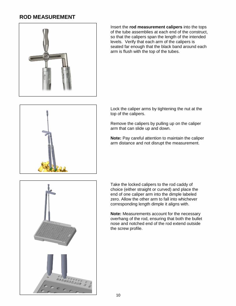
ROD MEASUREMENT
Insert the rod measurement calipers into the tops of the tube assemblies at each end of the construct, so that the calipers span the length of the intended levels. Verify that each arm of the calipers is seated far enough that the black band around each arm is flush with the top of the tubes.
Lock the caliper arms by tightening the nut at the top of the calipers. Remove the calipers by pulling up on the caliper arm that can slide up and down. Note: Pay careful attention to maintain the caliper arm distance and not disrupt the measurement.
Take the locked calipers to the rod caddy of choice (either straight or curved) and place the end of one caliper arm into the dimple labeled zero. Allow the other arm to fall into whichever corresponding length dimple it aligns with. Note: Measurements account for the necessary overhang of the rod, ensuring that both the bullet nose and notched end of the rod extend outside the screw profile.

11
FOR LONG CONSTRUCTS
In the event that the rod measurement calipers do not reach from end to end, depth sticks may be used to determine the length of the rod. Insert depth sticks through each tube tower for placement into each of the screw tulips.
Note: The depth sticks may also be used to verify the
rod position (see page 14).
The malleable rod template can be laid across the tops of each stick, in the u-shaped channels to determine proper length. For this method to be successful, each of the screw/tube assemblies must be held parallel to one another; perpendicular to the patient. For longer constructs, the malleable rod template can also be used to assist with capturing the appropriate contour needed for bending a straight rod. Note: The template does not account for either the bullet or notched end of the rod; 15 mm must be added to the length shown by the rod template.

12
ROD PLACEMENT
OFFSET ROD INSERTERS
Prior to placement of the rod, the muscle splitter may be used to create a pathway between the tube assemblies to facilitate rod insertion. Align the adjacent assembled tubes such that the full open slots are facing each other and the closed portions are facing outward. This position will allow for the rod to be inserted and guided into place.
The appropriate rod is selected and grasped. Choose from either the offset left, offset right or in-line rod inserters. Each inserter is designed to facilitate a different rod insertion approach, as needed by technique or anatomy.
The offset (Left and Right) inserters are recommended for shorter constructs. To load the rod, depress the button on the top of the device and slide the hex shaped end of the rod into the matching recess of the inserter. Note: Pay careful attention to the notch in the end of the rod, making sure that it points directly up along the axis of the instrument shaft.
Once the rod is in place, depress the button that is on the front of the inserter handle. This will activate the locking arm of the inserter and secure the rod. Verify that the rod can wiggle, but that it cannot come out.

13
The initial insertion of the rod should be as vertical as possible to have the most vertical rod approach angle into the screw tulip. The handle should be as parallel to the patient’s torso as possible, with the tip of the inserter held closely to the tube.
Once the rod is in the starting position, the handle should be rotated up, vertically. While moving into this position, a downward force should be applied, while also maintaining the inserter tip position relative to the tubes. Once the handle is vertical, the rod should be seated within the screw heads.
Each inserter is curved at the end, so that the inserter can wrap around the diameter of the tube assembly during insertion.
To release the inserter from the rod, depress the top button, and gently walk the inserter tip straight back, off the end of the rod. Note: During release, pay careful attention not to rock the inserter in the caudal-cranial or medial-lateral planes, as this may result in damage to the rod or inserter.

14
IN-LINE ROD INSERTER
When using the in-line rod inserter, prior to depressing the top button, the front trigger must first be held down. Once the top button is down, hold it there, while letting go of the front trigger. The top button will remain down and the rod can now be loaded.
Match the hex of the rod with that of the instrument, and make sure the notch in the rod faces up, towards the handle. With the rod held in place, depress the front button of the inserter, which will cause the device to pull the rod into the shaft of the instrument, securing it. Once in place, wiggle the rod to make sure it is secure.
With the bullet nose of the rod pointing straight down at the first screw, through the same incision, drive the rod down to the screw tulip. Carefully manipulate the inserter to bring it in line with the screw tulips.

15
TIP:
Once the rod is in place, hold the front button on the inserter, while the top button is depressed to disengage the inserter from the rod. Gently roll the handle of the inserter forward, while the top button is depressed aiding in the smooth release of the rod.
While using either inserter type, depth sticks are available to assist in verifying the position of the rod within each screw tulip. Place a depth stick into any screw/tube assembly where the rod position is uncertain. If the white band around the top of the depth stick is flush with the top of the screw/tube assembly, then the rod is within the screw tulip and is at the correct depth. If the depth stick band sits well above the screw/tube assembly, then the rod is within the screw/tube assembly, but is not fully seated. If the depth stick band sits below the top of the screw/tube assembly, then the rod is not within the screw/tube assembly and rod must be reinserted Note: Though the depth sticks have been designed to assist with rod placement verification, rod placement should primarily be confirmed and adjusted accordingly using fluoroscopy.
Rod Not Fully
Seated
Rod
Seated

16
ROD REDUCTION If the rod does not fully seat into the screw head, one of three different reduction instruments may be used.
Standard Reduction When the needed reduction is 10mm or less, the
standard rod pushers, threaded or non-threaded,
may be used to gently push down on the rod
through the tube assembly.
Supplemental Reduction
If 10mm-25mm of reduction is needed, the
parallel reducers may be used. Each parallel
reducer is a two-piece assembly that slides over
the tube assembly and locks into place simply by
pressing it on.
The parallel distracter handle can then be pressed
onto the pegged ends of the reducer assembly,
and the handles squeezed manually or by
translation of the threaded nut.
Repeat the reduction method at each screw, until
the set screws are at least provisionally tight at
each level. Confirm rod placement with
fluoroscopy and adjust accordingly.

17
If more than 25mm of reduction is required, the threaded reduction caps may be used. Each cap can be placed onto a tube assembly by pulling up on the outer collar of the cap and then pushing the cap down onto the top of the tube assembly. Each cap has three prongs that are designed to seat into one of the six oval windows at the top of the tube assembly. Align these prongs and then push the collar of the reduction cap down, thereby locking the cap to the top of the tower. Each reduction cap has a mating driver and tightener. Slide one tightener down through the top of a driver such that the hexed end of the tightener protrudes out of the end of the driver.
Place a set screw on the end of the tightener, making sure the gold side of the set screw is facing up along the shaft of the tightener.

18
Take this new subassembly and slide it down
through the reduction cap until the external
threads of the driver meet the internal threads of
the reduction cap. Thread the driver down until it
can no longer be moved by hand.
Utilize the reduction cap handle to continue
advancing the driver. The handle slides directly
over the driver and tightener. The handle is not
fully down until the bullet shaped head of the
driver disappears into the handle.

19
Note: It may be necessary to rotate the top portion of the handle to align the internal components before the driver will fully seat. Once the handle is in place, rotate the lower portion of the handle to advance the driver.
Once the black band around the top of the driver
has reached the top aspect of the reduction cap
(shown left), begin to rotate the top portion of
the handle. This action will rotate the set screw.
Note: For proper reduction of the rod to be
achieved the upper portion of the handle should
be turned 1 full turn for every ¼ turn of the lower
portion of the handle.
By advancing the lower portion of the handle relative to the upper portion at a ratio of 1:4, the set screw will engage the screw tulip and trap the rod. Repeat the reduction method at each screw, until the set screws are at least provisionally tight at each level. Confirm rod placement with fluoroscopy and adjust accordingly.
The upper portion
of the handle
engages and turns
the set screw.
The lower portion
of the handle
advances the rod.
Note: 1 full
turn of the
upper portion
of the handle
for every ¼ of
the lower
portion of the
handle

20
SET SCREW INSERTION
Place a set screw on each end of the set screw starter, making sure the gold anodized (gold) side is facing up. Insert the set screw starter down the center of the assembled tubes until it reaches the threads of the screw head. With a clock-wise rotation start the set screw into the threads. Note: Do not tighten all the way down, allowing for compression/distraction or rod adjustment. After verifying rod position using fluoroscopy, set screws can be final tightened to [9.0Nm (80in-lb)], if no compression or distraction is required.
Final tighten each of the set screws by utilizing the counter torque tube holder attached to the top of the tube assembly. Secure the set screw with the set screw tightener attached to
the [9.0Nm (80in-lb)] torque limiting T-handle.

21
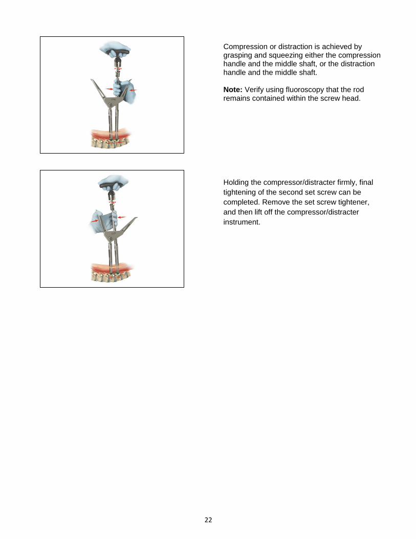
COMPRESSION / DISTRACTION
Compression or distraction is accomplished utilizing a single instrument, the compressor /distracter. Insert the solid, long shaft of the compressor/distracter into the tube assembly that has been fully tightened. Place the set screw tightener down the middle shaft of the compressor/distracter and fully seat it into the set screw. Once in position, tighten the knob on either side of the compressor/distracter as indicated by the markings. Tip: Leave at least 5mm, or a finger’s thickness, space between the tops of the tubes to allow for compression. .
22
Compression or distraction is achieved by grasping and squeezing either the compression handle and the middle shaft, or the distraction handle and the middle shaft. Note: Verify using fluoroscopy that the rod remains contained within the screw head.
Holding the compressor/distracter firmly, final
tightening of the second set screw can be
completed. Remove the set screw tightener,
and then lift off the compressor/distracter
instrument.
23
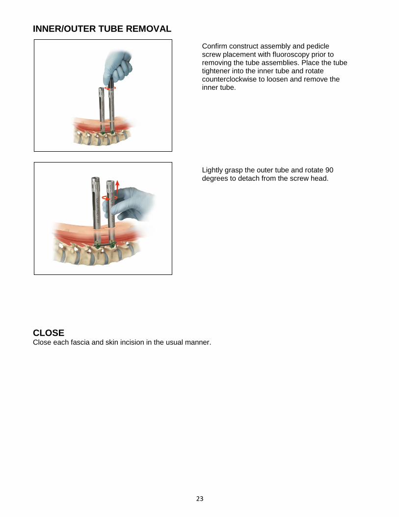
INNER/OUTER TUBE REMOVAL
CLOSE Close each fascia and skin incision in the usual manner.
Confirm construct assembly and pedicle screw placement with fluoroscopy prior to removing the tube assemblies. Place the tube tightener into the inner tube and rotate counterclockwise to loosen and remove the inner tube. Lightly grasp the outer tube and rotate 90 degrees to detach from the screw head.

24
IMPLANT REMOVAL Deterioration of the device after bone consolidation cannot be considered to constitute a dysfunction or deterioration in the characteristics of the implant. The implant can be removed after the consolidation of the bone graft. If a nonunion develops or if the components loosen, bend, and/or break, revise and/or remove the device(s) immediately before serious injury occurs. Failure to immobilize a delayed nonunion of bone will result in excessive and repeated stresses on the implant. By the mechanism of fatigue these stresses can cause eventual bending, loosening, or breakage of the device(s). The implant may be removed after healing. Particularly in young active patients, implants may loosen, fracture, corrode, migrate, and increase the risk of infection, cause pain, or stress shield bone – even after normal healing. The surgeon must consider the risks and benefits when deciding whether or not to remove an implant. Implant removal must be followed by careful postoperative management to avoid re-fracture. If the patient is older and has a low activity level, the surgeon may elect not to remove the implant in order to eliminate the risks of another surgery. If the screws/construct must be removed, begin by placing the set screw tightener in any of the available set screws. This tightener will act as a guide for the reinstallation of the outer middle tube. Slide the outer middle tube over and down along the tightener, until it comes to rest on the top of the screw. Orient the slot of the outer tube so that it is perpendicular to the run of the rod. Rotate the outer middle tube slowly and with a small amount of downward force ninety degrees, or until you can feel it to be seated down about 3-4mm. Rotate the outer middle tube back to its original starting position. Repeat this process until the outer middle tube feels securely joined to the screw head. With the outer middle tube and set screw tightener still in place, slide the inner middle tube down along the tightener. Thread the top portion of the inner middle tube into the outer middle tube until no space can be seen between the top of the outer middle tube and the bottom of the head of the spinning aspect of the inner middle tube. It may be necessary to carefully rock the tubes and tightener, in order for the inner middle tube to fully seat. Repeat this process for each screw to be removed.
With the tubes reattached, use the counter torque handle and the set screw tightener to unthread each of the set screws. Use any of the standard handles counter clockwise in this process, except for the torque limiting handle. Using the torque handle in this application will damage the torque limiting feature of the instrument and void its calibration cycle. With the set screws removed, use the rod forceps to pull the rod from the construct. Do not attempt to reattach the offset or in-line rod inserters. With the rod removed, place the bone screw driver and bone screw driver sleeve down into the tube. Thread the sleeve down until it is flush with the top of the tube assembly. If the sleeve will not seat flush, rotate the entire tube assembly about the screw axis until the driver drops into the pockets that are present on the top of the screw shank. With the sleeve fully seated and the bone screw driver engaged, back the screw out of the bone. Repeat this process until all desired screws have been removed.

25
TELLURIDE IMPLANTS
Screw Diameter Screw Length Rod Rod Length 5.5mm 30, 35, 40, 45 & 50mm Pre-Bent 35, 40, 45, 50, 55, 60, 65, 70, 75, 80, 90, 100, 110 & 120mm 6.5mm 30, 35, 40, 45, 50 & 55mm Straight 35, 40, 45, 50, 55, 60, 65, 70, 75, 80, 90, 100, 110, 120, 7.5mm 30, 35, 40, 45, 50 & 55mm 130, 140, 150, 160, 170, 180, 190, 200, 300 & 400mm 8.5mm 30, 35, 40, 45, 50 & 55mm
Case 1: 7706-3501 – Screws and Pedicle Prep Instruments

26
Case 2: 7706-3601 – Screw Towers and Rod Reduction Instruments

27
Case 3: 7706-3701 – Rods and Rod Insertion Instruments

28
Case 4: 7706-3801 – Ancillary Screw Towers and Rod Reduction Instruments

29
IMPORTANT INFORMATION ON THE TELLURIDE 2 MIS SPINAL FIXATION SYSTEM Device Description The Telluride 2 device is a posterior attachment spinal fixation system composed of screws, rods, set screws, dedicated surgical instruments, and sterilization cases. The components are used to build a construct to provide stabilization of spinal segments in the thoracic, lumbar, and sacral spine to support fusion. The Telluride 2 device is part of the Biomet Spinal Fixation System, which offers the surgeon a variety of implant components from which to assemble a suitable construct according to each individual patient’s needs and requirements. After a solid fusion occurs, the system serves no functional purpose and should be removed. Removal is indicated because the implants are not intended to transfer or support forces developed during normal activities. However, any decision to remove the device must be made by the physician and the patient, taking into consideration the patient’s general medical condition and the potential risk to the patient of a second surgical procedure. Indications for Use The Telluride 2 system is intended to be used to help provide immobilization and stabilization of spinal segments in skeletally mature patients as an adjunct to fusion of the thoracic, lumbar, and/or sacral spine. The system is intended for use with autograft or allograft. The Telluride 2 device is intended for posterior, non-cervical (T1-S2/Ilium) pedicle and non-pedicle spinal fixation, to provide immobilization and stabilization of spinal segments in skeletally mature patients as an adjunct to fusion in the treatment of the following instabilities or deformities: degenerative disc disease (DDD, defined as back pain of discogenic origin with degeneration of the disc confirmed by history and radiographic studies); spondylolisthesis; trauma (i.e. fracture or dislocation); spinal stenosis; deformities or curvatures (i.e. scoliosis, kyphosis and/or lordosis); tumor; pseudarthrosis; and failed previous fusion. Contraindications Contraindications may be relative or absolute. The choice of a particular device must be carefully weighed against the patient’s overall evaluation. Circumstances listed below may reduce the chance of a successful outcome. Contraindications include, but are not limited to: • Allergy to titanium or cobalt chrome alloys, or foreign body sensitivity. Where material sensitivity is suspected, appropriate tests should be made prior to implantation.
• Known or suspected infection/immune system incompetence. Acute or chronic infectious diseases of any etiology or localization. • Any abnormality present which affects the normal process of bone remodeling including, but not limited to, severe osteoporosis involving the spine, bone absorption, osteopenia, active infection at the site or certain metabolic disorders affecting osteogenesis. • Morbid Obesity. An overweight or obese patient can produce loads on the spinal system, which can lead to failure of the fixation of the device or failure of the device itself. • Any neuromuscular deficit which places an unusually heavy load on the device during the healing period. • Open Wounds. • Pregnancy. • Any other medical or surgical condition which would preclude the potential benefit of spinal surgery, such as the presence of congenital abnormalities, elevation of sedimentation rate unexplained by other diseases, elevation of the white blood count (WBC), or a marked left shift in the WBC differential count. • Any case requiring the mixing of components from other manufactures’ systems. • Any case requiring the mixture of stainless steel with titanium, or stainless steel with cobalt chrome implant components. • Fever or leukocytosis. • Signs of local infection or inflammation. • Previous history of infection. • Alcoholism or heavy smoking. • Senility, mental illness or substance abuse, of a severity that the patient may ignore certain necessary limitations and precautions in the use of the implant, leading to failure or other complications. • Any patient unwilling to follow post-operative instructions. • Inadequate tissue coverage over the operative site.

30
Possible Complications Possible complications specific to the device may include: • Early or late implant bending, breakage, failure, loosening or movement/migration • Bone fracture • Allergic reaction to implant material Other general complications associated with any spinal surgical procedure may include: non-union or delayed union; pseudarthrosis; pain; second surgery; bleeding; infection, early and late; tissue or nerve damage, including dural tears or other neurological problems; incisional complications; scar formation; damage to blood vessels and cardiovascular system compromise; changes in mental status; damage to internal organs and connective tissue; complications due to the use of bone grafting, including graft donor site complications; respiratory problems; reactions to anesthesia and/or death. Warnings The safety and effectiveness of pedicle screw spinal systems have been established only for spinal conditions with significant mechanical instability or deformity requiring fusion with instrumentation. These conditions are significant mechanical instability or deformity of the thoracic, lumbar and sacral spine secondary to severe spondylolisthesis (grades 3 and 4) of the L5-S1 vertebra, degenerative spondylolisthesis with objective evidence of neurological impairment, fracture, dislocation, scoliosis, kyphosis, spinal tumor, and failed previous fusion (pseudarthrosis). The safety and effectiveness of these devices for any other conditions are unknown. Patients with previous spinal surgery at the levels to be treated may have different clinical outcomes than previous surgical outcomes. Precautions • The Telluride 2 implants are for single use only. Never reuse any implant even if it appears unmarked or undamaged. Reuse of the implant components may result in reduced mechanical performance, malfunction, or failure of the device. Any implant implanted and then removed must be discarded. Use only new implants for each case. • The implantation of pedicle screw spinal systems must only be performed by experienced spinal surgeons with specific training in the use of this pedicle screw spinal system due to the technically demanding procedure presenting a risk of serious injury to the patient. • Based on the fatigue testing results, the physician/surgeon must consider the levels of implantation, patient weight, patient activity level, other patient conditions, etc. which may impact on the performance of the system.
• Preoperatively: The surgeon must be fully conversant with all aspects of the surgical technique and know the indications and contra-indications of this type of implant. The surgeon must have acquainted himself before the operation with the specific technique for insertion of the product, which is available from the manufacturer. As part of the pre-operative examination, the surgeon must check that no biological, biomechanical or other factors will affect the correct conduct of the operation and the post-operative period. An appropriate range of implant sizes must be available at the time of the operation. • Intraoperatively: The correct selection of the type and size of implant appropriate to the patient and the positioning of the implant are extremely important. • Failure to place the set screw as instructed (gold top surface is visible prior to insertion) could result in a failure of the instrumentation to properly lock in place as intended. This may result in patient injury. • Postoperatively: Patients must be informed of the precautions to be taken in their everyday life to guarantee a maximum implant service life. It is recommended that regular postoperative follow-up is undertaken to detect early signs of failure of the implants and to consider the action to be taken. Deterioration of the device after bone consolidation cannot be considered to constitute a dysfunction or deterioration in the characteristics of the implants. The implant can be removed after bony healing. • The Telluride 2 device has not been evaluated for safety and compatibility in the magnetic resonance (MR) environment. The Telluride 2 device has not been tested for heating or migration in the MR environment. • Mixing of dissimilar metals can accelerate or initiate the corrosion process. Titanium components must NOT be used together in building a construct that involves other implant materials. Titanium and cobalt chrome may be used together within the same construct. • The implant and instrument components of the Telluride 2 system should NOT be used with the implant or instrument components from any other system or manufacturer. • Federal law (USA) restricts this device to sale by or on the order of a physician.

31
All content herein is protected by copyright, trademarks and other intellectual property rights owned by or licensed to BIOMET, Inc. or its affiliates unless otherwise indicated, and must not be redistributed, duplicated or disclosed, in whole or in part, without the express written consent of BIOMET. This material is intended for health care professionals and the BIOMET sales force. Distribution to any other recipient is prohibited. For complete product information, including indications, contraindications, warnings, precautions, and potential adverse effects, see the package insert. This technique was prepared in conjunction with a licensed health care professional. The treating surgeon is responsible for determining the appropriate treatment, technique(s), and product(s) for each individual patient. PRODUCT COMPLAINTS — Communicate suspected deficiencies in product quality, identity, durability, reliability, safety, effectiveness and/or performance directly to BIOMET SPINE by email: [email protected] or phone: 866.956.7579. When fi ling a complaint, please provide the component name(s), part number(s), lot number(s), your name and address, the nature of the complaint, surgeon name and the date you became aware of the complaint. Sterilize and return all component(s) to your local BIOMET SPINE representative. Notify BIOMET SPINE immediately of an incident resulting in patient death or serious injury. If further directions for use of this system are needed, contact BIOMET SPINE Customer Service by email: [email protected], phone: 866.378.4195 or fax: 303.443.7501.

32
At Biomet, engineering excellence is our heritage
and our passion. For over 25 years, through
various divisions worldwide, we have applied the
most advanced engineering and manufacturing
technology to the development of highly durable
systems for a wide variety of surgical applications.
To learn more about this product, contact your local
Biomet Sales Representative today.
Broomfield, CO • 800.447.3625 www.biomet.com • LIT7710-0113.02
©2014 BIOMET SPINE, LLC. All rights reserved. All trademarks are the property of BIOMET, Inc. or one of its subsidiaries, unless otherwise indicated. Rx Only.