Embed Size (px)
Citation preview

ATC200-1000 & ATC300-1000/2000 Teletilt® Remote Control Variable
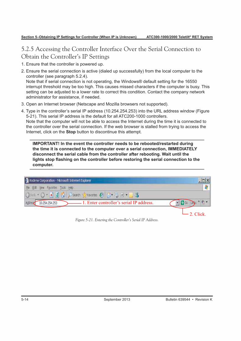
Electrical Downtilt System
Installation and User Guide
Bulletin 639544 • Revision K • September 2013
© 2013 CommScope Bulletin 639544
Notice: CommScope disclaims any liability or responsibility for the results of improper or unsafe installation, inspection, maintenance, or removal practices.Aviso: CommScope no acepta ninguna obligación ni responsabilidad como resultado de prácticas incorrectas o peligrosas de instalación, inspección, mantenimiento o retiro.Avis : CommScope décline toute responsabilité pour les conséquences de procédures d’installation, d’inspection, d’entretien ou de retrait incorrectes ou dangereuses.Hinweis: CommScope lehnt jede Haftung oder Verantwortung für Schäden ab, die aufgrund unsachgemäßer Installation, Überprüfung, Wartung oder Demontage auftreten.Atenção: A CommScope abdica do direito de toda responsabilidade pelos resultados de práticas inadequadas e sem segurança de instalação, inspeção, manutenção ou remoção.Avvertenza: CommScope declina eventuali responsabilità derivanti dell’esecuzione di procedure di installazione, ispezione, manutenzione e smontaggio improprie o poco sicure.
CommScope1100 CommScope Place SE P.O. Box 339, Hickory, NC 28603-0339(828) 324-2200 (800) 982-1708www.commscope.com/andrew
Customer Service 24 hoursNorth America: +1-800-255-1479, Option 1 (toll free)Any country: +1-779-435-6500, Option 1email: [email protected]

ATC300-1000/2000 Teletilt® RET System ATC300-1000/2000 Teletilt® RET System
Bulletin 639544 • Revision K September 2013 i
Revision HistoryRevision No. Date Description of Changes
A December 2007 Released
B October 2008 Added instructions on how to configure the controller to operate using an SNMP agent (Section 8).Moved instructions on Uploading Firmware Manually to Appendix C.Rewrote instructions on Uploading Device Firmware, which includes how to change AISG mode in device (Sec-tion 10).Added instructions on AISG Reset Capabilities and Using AISG Control Tools to Section 11.Added instructions on manually setting an IP address for Windows Vista operating systems to Appendix B.
C November 2008 Added 3 sections about Multiple Integrated Actuators.Added SmartBeam Antenna Sections to explain configu-ration and adjustments.Added Section 23 to explain Tower Mounted Amplifiers.
D May 2009 Section 7 introduces bus is externally powered feature.Section 9 changes from download the antenna definition file to antenna definition file releases are bundled with controller firmware.Section 10 explains the Firmware Bundle Version Num-bering.Added Section 10.4, Using the Controller Help Menu: About and Software Versions.Section 11 added 64 device database expansion.Section 12 introduces generic antenna model naming.Section 15 shows addition of 1-way SmartBeam® antennas.
E December 2009 DHCP added to Sections 6, 7, and Appendix B.F May 2010 Update ATC300-1000 Operations Manual to also cover
ATC200-1000 Operations Manual.G November 2010 Correct drawing.H August 2012 Change ATC300/ATC200 Operations Manual to support
ATC300 release 2.34_A.

ii September 2013 Bulletin 639544 • Revision K
ATC300-1000/2000 Teletilt® RET System
Revision No. Date Description of Changes
J December 2012 Change ATC300/ATC200 Operations Manual to supportATC300-2000 and Software release 2.36.
K September 2013 Updated section 23 to better describe changing TMA Gain.
Bulletin 639544 • Revision K September 2013 iii
ATC300-1000/2000 Teletilt® RET System
Installation Training Available at Andrew Institute
Do not install near power lines. Power lines, telephone lines, and guy wires look the same. Assume any wire or line can electrocute you.
Do not install on a wet or windy day or when lightning or thunder is in the area. Do not use metal ladder.
Wear shoes with rubber soles and heels. Wear protective clothing including a long-sleeved shirt and rubber gloves.
Notices and PrecautionsIMPORTANT
Before installing/operating the ATC300-1000/2000 controller, please DOWNLOAD the latest controller software from the Commscope web site at www.commscope.com. Please register online to receive E-mail notifications for software updates.
SAFETY NOTICEThe installation, maintenance, or removal of an antenna requires qualified, experienced personnel. Andrew installation instructions are written for such installation personnel. Antenna systems should be inspected once a year by qualified personnel to verify proper installation, maintenance, and condition of equipment.
Andrew disclaims any liability or responsibility for the results of improper or unsafe installation prac-tices.
It is recommended that transmit power be turned off when the field installation is performed. Follow all applicable safety precautions as shown on this page.
WARRANTY NOTICEProper installation procedures must be followed when installing and operating RET equipment. Failure to assure installations are done properly by trained installation personnel and to follow procedures discussed in this bulletin may cause warranty for such products to be void.
Andrew requires pretesting actuators on the ground prior to installation, using the Andrew portable controller and the latest version of the controller software (available online at www.commscope.com/andrew under Products→Antennas→Teletilt® RET System). This will verify proper actuator functionality and also ensure that the latest available actuator firmware release is installed on the actuator. Failure to conduct pre-test and pre-installation procedures defined by Andrew will void warranty.
Unauthorized removal of a protective shroud to replace actuators voids the Andrew warranty.
CAUTIONIf using the 48V power connection on the ATC200-1000, ensure wires are properly connected. Reversing the wires can cause permanent damage to the controller.
iv September 2013 Bulletin 639544 • Revision K
ATC300-1000/2000 Teletilt® RET System
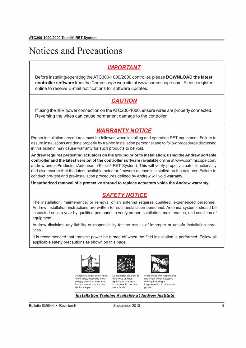
Electric Static Discharge (ESD) can damage or destroy the hardware equipment used for the ATC300-1000/2000 Teletilt® System. ESD can oc-cur during handling of equipment without the user feeling a shock. The following precautions should be taken to prevent ESD.1. Wear an ESD wrist strap (Figure 1) and/or
use a test lead (ground), such as a single-wire conductor with a series resistance of 1 megohm equipped with alligator clips on each end. In using a ground, one end of the alligator clip is connected to a grounded equipment frame and the other end of the alligator clip is touched with a bare hand.
2. Other precautions the user may take to reduce the risk of ESD are:
• avoid wearing clothing that conducts static electricity, such as wool
• remove all jewelry • avoid handling equipment during an elec-
trical storm3. Before opening a package containing an elec-
trostatic unit or an electrostatic sensitive device/assembly, clip the free end of a test lead to the package. Leave the other end connected to the equipment frame or other ESD ground. This will cause any static electricity which may have built up on the package to discharge. Keep the unit package grounded during removal or placement of equipment in the package.
4. Minimize handling of ESDS (Electric Static Discharge Sensitive) equipment. Keep replace-ment equipment in the electrostatic-free packaging (with ground established between packaging and equipment frame) until needed. Repairable ESD equipment should be placed in the electrostatic-free packaging (with ground connecting package to equipment frame) upon removal from ATC300-1000/2000 system. ESD equipment should only be transported and stored in ESD protective packaging.
5. Always avoid unnecessary movement of body, such as scuffing feet across flooring, when handling ESDS equipment. Such movement will generate additional charges of static electricity.
Figure 1. ESD Wrist Strap.
WARNING
It is very important to disconnect the ATC200-1000 controller from the system after each use to prevent permanent damage to the system.

Bulletin 639544 • Revision K September 2013 v
ATC300-1000/2000 Teletilt® RET System
6. When removing or replacing ESDS equipment, hold the device or assembly through the electrostatic-free wrap, where possible. If this is not possible, lift the device or assembly by its body only. Do not touch component leads, connector pins, or any other electrical connections or paths, even though they are covered by conformal coating.
7. Do not allow ESDS equipment to come in contact with clothing or other ungrounded ma-terials that may have an electrostatic charge. Charges on non-conductive material are not equal. For instance, a plastic storage bag may have a –10,000 volt potential 1/2 inch from a +15,000 volt potential with many such charges all over the bag. Do not hand ESD equipment to another person until it is safely packaged for protection for ESD.
8. When moving ESDS equipment, always touch the surface on which it rests with bare skin for at least one second before lifting. Before setting it on any surface, touch the surface with your free hand for at least one second. Contact with bare skin provides a safe discharge path for charges accumulated while you are moving around.
9. While servicing equipment containing ESD devices, do not handle or touch materials such as plastic, vinyl, synthetic textiles, polished wood, fiberglass, or similar items that can generate static charges; unless you repeat the grounding process with bare hands after contacting these materials.
10. Where possible, avoid repairs that require soldering at the equipment level. Soldering irons must have heater/tips assemblies that are grounded to an electrical ground. Do not use standard plastic solder suckers (special antistatic solder suckers are commercially available).
11. Ground the leads of test equipment momentarily before you energize the test equipment and before you probe ESD devices or assemblies.
12. Work benches used for setting ESDS equipment should have ESD protective work sur-faces. These work benches should also have personnel ground straps. These straps prevent discharge of static electricity from personnel handling ESDS items on the work bench surface. The work bench surface should be connected to a ground through a ground cable. The resistance in the bench top ground cable should be located at or near the point of contact with the top of the work bench. The resistance should be high enough to limit any leakage current to 5 milliamperes or less. This takes into consideration the highest voltage source within reach of grounded people and all the parallel resistances to ground, such as wrist ground straps, table tops, and conductive flooring.

vi September 2013 Bulletin 639544 • Revision K
ATC300-1000/2000 Teletilt® RET System
This page intentionally left blank.
Bulletin 639544 • Revision K September 2013 vi
Table of Contents
Revision History .................................................................................................... i
Notices and Precautions ....................................................................................... iii
Part 1 – Initial Setup
Section 1 System Description ......................................................................................1-11.0 Section Overview ....................................................................................................... 1-11.1 ATC200-1000 Antenna System Controller ................................................................ 1-11.2 ATC300-1000/2000 Antenna System Controller ........................................................ 1-21.2.1 Modem Port Isolation (ATC300-2000 only) ............................................................... 1-81.3 Actuator (Motor Drive) .............................................................................................. 1-101.4 Junction Boxes ......................................................................................................... 1-111.5 Lightning Protection Unit .......................................................................................... 1-111.6 Low Voltage Cable Assemblies (AISG Compliant RET Control Cabling) ................. 1-12
Section 2 Installation Instructions and Safety Precautions ..........................................2-12.0 Section Overview ....................................................................................................... 2-12.1 Abbreviations .............................................................................................................. 2-12.2 Installation Preparations ............................................................................................. 2-12.3 Controller Chassis Mounting ...................................................................................... 2-22.4 Controller Chassis Grounding .................................................................................... 2-22.5 Controller Chassis Power ........................................................................................... 2-3
Section 3 Changing IP Settings on Local Computer Using the IP Config Tool ............3-13.0 Section Overview ....................................................................................................... 3-13.1 Downloading/Extracting the IP Config Tool Zip File .................................................... 3-13.2 Installing the Andrew IP Config Tool ........................................................................... 3-23.3 Launching the IP Config Tool ...................................................................................... 3-33.4 Changing the IP Address on the Local Computer ...................................................... 3-43.5 Backing Up New IP Settings for the Local Computer ................................................. 3-63.6 Restoring Original IP Settings on the Local Computer ............................................... 3-83.7 Restoring Backup Files for New IP Settings on the Local Computer for Regaining Access to the Controller ............................................................................................. 3-93.8 Removing a Backup File .......................................................................................... 3-10
Section 4 Changing IP Settings on Local Computer Manually ....................................4-14.0 Section Overview ....................................................................................................... 4-14.1 Changing the IP Address on the Local Computer ...................................................... 4-2

Table of Contents ATC300-1000/2000 Teletilt® RET System
ii December 2009 Bulletin 639544 • Revision Evii September 2013 Bulletin 639544 • Revision K
4.2 Restoring Original IP Settings on the Local Computer ............................................... 4-6
Section 5 Obtaining IP Settings for Controller (When IP Is Unknown) .....................5-15.0 Section Overview ....................................................................................................... 5-15.1 Establishing the IP Settings on an ATC300-1000/2000 .............................................. 5-15.1.1 Establishing a Serial Connection to the Controller ................................................... 5-15.2 Determining the IP settings on an ATC200-1000 ....................................................... 5-75.2.1 Establishing a Serial Connection to the Controller ................................................... 5-75.2.2 Configuring the Serial Connection.......................................................................... 5-105.2.3 Establishing a Serial Connection for Windows® 2000 Users .................................. 5-125.2.4 Activating the Serial Connection ............................................................................ 5-135.2.5 Accessing the Controller Interface Over the Serial Connection to Obtain the Controller’s IP Settings ..................................................................................... 5-14
Part 2 – Accessing the Controller
Section 6 Accessing the Controller Using a Direct Ethernet Connection ....................6-16.0 Section Overview ....................................................................................................... 6-16.1 Using an Ethernet Cable for Establishing a Direct Connection from a Local Computer to the Controller ......................................................................................... 6-1
Section 7 Changing the Controller's IP Settings for Access Over a Network ..............7-17.0 Section Overview ....................................................................................................... 7-17.1 Configuring the Controller Using A Local Computer ................................................... 7-27.1.1 Configuring the Controller to Use A Static IP Address .............................................. 7-37.1.2 Configuring the Controller to Use DHCP .................................................................. 7-47.2 Accessing the Controller Over the Network Connection ............................................ 7-6
Section 8 Controller Configuration Options ...............................................................8-18.0 Section Overview ...............................................................................................8-18.1 Configuring the Controller for an SNMP Manager .................................................8-18.2 Security and Site Sharing (ATC300-1000/2000 only) .............................................8-38.2.1 Site Sharing Configuration ................................................................................8-58.2.1.1 Operator Name and Password Management ....................................................8-58.2.1.2 Assigning Operators to Devices .......................................................................8-68.2.1.3 Operator Login/Logout ....................................................................................8-78.3 Site Configuration ...............................................................................................8-88.3.1 Site Name.................................................................................................................8-88.3.2 External Bus Power (ATC300-1000/2000 only) ........................................................8-88.3.3 Alarm Relay Configuration (ATC300-1000/2000 only) .............................................8-8
Part 3 – Uploading Firmware
Section 9 Uploading Controller Firmware and Antenna Definition Files Using the IP Config Tool .............................................................................9-19.0 Section Overview ....................................................................................................... 9-1
ATC300-1000/2000 Teletilt® RET System Table of Contents
Bulletin 639544 • Revision E December 2009 iii
9.1 Required Resources ................................................................................................... 9-19.2 Connecting to the Controller ....................................................................................... 9-29.3 Locating/Adding Firmware Files to FTP Server .......................................................... 9-59.4 Uploading Firmware Files to the Controller ................................................................ 9-89.5 Uploading Other Antenna Supplier Definition Files .................................................. 9-109.6 FTP Server Conflict .................................................................................................. 9-109.7 Uploading Controller Firmware from the ATC300 Web Interface ............................. 9-11
Section 10 Uploading Device Firmware ....................................................................10-110.0 Section Overview .................................................................................................... 10-110.1 Scan for Devices ..................................................................................................... 10-110.2 Updating AISG Device Firmware ............................................................................ 10-210.3 Choice of Upgrade Method ..................................................................................... 10-510.4 Using the Controller Help Menu .............................................................................. 10-7
Part 4 – Device Discovery for All Types of Antennas
Section 11 Device Discovery and Bus Management ..................................................11-111.0 Section Overview ..................................................................................................... 11-111.1 Running a Device Search ......................................................................................... 11-111.2 Manually Adding a Device to the Controller's System .............................................. 11-311.3 Addressing ............................................................................................................... 11-411.4 Removing a Device from the Controller's System .................................................... 11-411.5 AISG Control Tools ................................................................................................... 11-611.5.1 AISG 2.0 Reset..................................................................................................... 11-611.5.2 Revert to AISG 1.1................................................................................................ 11-711.5.3 Using the AISG Control Tools ............................................................................... 11-711.6 Andrew AITM Actuator Mode Management (ATC300 2.34_A and later only) .......... 11-811.6.1 Set AITM(s) to Multiple-Single RET Mode ............................................................ 11-911.6.2 Set AITM(s) to MultiRET Mode ........................................................................... 11-12
Part 5 – Operating Instructions for Standard Antennas with Attached Actuators
Section 12 Device Configuration ..............................................................................12-112.0 Section Overview ..................................................................................................... 12-112.1 Configuring a Device ................................................................................................ 12-112.2 Generic Antenna Model Naming............................................................................... 12-412.3 Saving a Device Configuration to File ...................................................................... 12-5
Section 13 Adjusting the Electrical Downtilt on a Single Antenna ............................13-113.0 Section Overview ..................................................................................................... 13-113.1 Adjusting the Downtilt Angle on a Single Antenna .................................................... 13-1
Bulletin 639544 • Revision K September 2013 viii
Table of Contents ATC300-1000/2000 Teletilt® RET System
iv December 2009 Bulletin 639544 • Revision Eiv July 2008 Bulletin 639544 • Revision Bix September 2013 Bulletin 639544 • Revision K
Section 14 Adjusting the Electrical Downtilt on a Group of Antennas ......................14-114.0 Section Overview ..................................................................................................... 14-114.1 Adjusting the Downtilt Angle on a Group of Antennas .............................................. 14-1
Part 6 – Operating Instructions for Antennas with Multiple Integrated Actuators
Section 15 Device Configuration for Antennas with Multiple Integrated Actuators ..15-115.0 Section Overview ..................................................................................................... 15-115.1 Configuring a Device ................................................................................................ 15-115.2 Saving a Device Configuration to File ...................................................................... 15-4
Section 16 Adjusting the Electrical Downtilt on a Single Antenna Equipped with Multiple Integrated Actuators .................................................................16-1
16.0 Section Overview ..................................................................................................... 16-116.1 Adjusting the Downtilt Angle on a Single Antenna .................................................... 16-1
Section 17 Adjusting the Electrical Downtilt on a Group of Antennas Equipped with Multiple Integrated Actuators .................................................................17-1
17.0 Section Overview ..................................................................................................... 17-117.1 Adjusting the Downtilt Angle on a Group of Antennas .............................................. 17-1
Part 7 – Operating Instructions for SmartBeam® Antennas
Section 18 Device Configuration with SmartBeam Antennas ...................................18-118.0 Section Overview ..................................................................................................... 18-118.1 Configuring a Device ................................................................................................ 18-118.2 Saving a Device Configuration ................................................................................. 18-4
Section 19 Adjusting the Electrical Downtilt on a Single SmartBeam® Antenna .......19-119.0 Section Overview ..................................................................................................... 19-119.1 Adjusting the Downtilt Angle on a Single Antenna .................................................... 19-1
Section 20 Adjusting the Pan on a Single SmartBeam® Antenna ..............................20-120.0 Section Overview ..................................................................................................... 20-120.1 Adjusting the Pan on a Single Antenna .................................................................... 20-1
Section 21 Adjusting the Fan on a Single SmartBeam® Antenna ...............................21-121.0 Section Overview ..................................................................................................... 21-121.1 Adjusting the Fan on a Single SmartBeam Antenna ................................................ 21-1
Section 22 Adjusting the Electrical Downtilt, Pan, or Fan on a Group of SmartBeam® Antennas .................................................................................................22-1
22.0 Section Overview ..................................................................................................... 22-1
ATC300-1000/2000 Teletilt® RET System Table of Contents
Bulletin 639544 • Revision K September 2013 x
22.1 Adjusting the Downtilt Angle, Az Offset, or Beamwidth on a Group of SmartBeam Antennas .................................................................................................................. 22-1
Part 8 – Operating Instructions for Tower Mounted Amplifiers
Section 23 Tower Mounted Amplifier .......................................................................23-123.0 Section Overview ..................................................................................................... 23-123.1 AISG TMA (Tower Mounted Amplifier) Applications ................................................. 23-123.2 Finding TMAs ........................................................................................................... 23-123.3 Configuring a TMA .................................................................................................... 23-323.4 Changing TMA Gain ................................................................................................. 23-523.5 Changing TMA Operating Mode ............................................................................... 23-7
Part 9 – Helpful Information
Appendix A Disabling and Enabling the Windows® XP SP2 Firewall .........................A-1A.0 Appendix Overview ....................................................................................................A-1A.1 Opening the Security Center ......................................................................................A-1
Appendix B IP Addressing ......................................................................................... B-1B.0 Appendix Overview ....................................................................................................B-1B.1 IP Settings ..................................................................................................................B-1B.2 Setting An IP Address Using Windows Vista ..............................................................B-2
Appendix C Uploading Firmware to Controller Manually ..........................................C-1C.0 Section Overview .......................................................................................................C-1C.1 Required Resources ...................................................................................................C-2C.2 Installing, Configuring, and Running the FTP Server (not needed for ATC300 2.34 and later) ....................................................................................................................C-2C.3 Uploading the Firmware Bundle to the Controller ......................................................C-4C.4 Uploading Firmware to AISG Devices using the ATC300/200 Controller ...................C-7C.5 Verifying ATC300/200 Software Versions .................................................................C-10C.6 Verifying AISG Device Firmware Versions ...............................................................C-10
Appendix D ATC300-1000/2000 Relay Alarms .................................................... D-1D.0 Relay Alarm Definitions Table .....................................................................................D-1D.1 Relay Alarm Information .............................................................................................D-1
Appendix E Declaration of Compliance ..............................................................E-1
Site Configuration Worksheet ..................................................................(Tear Out Page)

Table of Contents ATC300-1000/2000 Teletilt® RET System
xi September 2013 Bulletin 639544 • Revision K
This page intentionally left blank.

Bulletin 639544 • Revision K September 2013
Part 1Initial Setup

Part 1–Initial Setup ATC300-1000/2000 Teletilt® RET System
September 2013 Bulletin 639544 • Revision K
This page intentionally left blank.

Section 1System Description
1.0 Section OverviewThis section discusses the use of components used in the ATC300-1000/2000 or ATC 200-1000 Teletilt® system.
1.1 ATC200-1000 Antenna System Controller The ATC200-1000 controller, shown in Figure 1-1, serves as an interface between a local PC/lap-top or a company network and the remote electrical downtilt devices (actuators/TMAs). This unit uses software designed for communication between the controller and its attached AISG devices. To download the latest software, go to the Andrew Products tab on www.commscope.com, click onAndrew→Products→Antennas→Teletilt RET System→Downloads→RET Controller Software and Firmware ATC200-1000 Bundle.
Communication Ports and Power Connections (Figure 1-1):• 9–pin ‘D’ style RS–232 connector port used to connect to a local PC’s COM port • Ethernet port used to connect to a local PC’s Ethernet port or a network/Internet• Both dc and ac connections for the power supply module• 8–pin connector port (RET) for the AISG (Antenna Interface Standards Group) control cable as-
sembly, which is used to manage up to 32 AISG devices, e.g. actuators or TMAsIncludes:• 4 Power cords (Australia/Asia, Europe, UK, and North America)• Ethernet crossover cable• Phoenix 48 Volt power connector (Caution! Ensure wires are properly connected. Reversing wires can cause permanent damage to the controller.)• Site Configuration Sheet (Contact your Andrew Sales Representative for ordering this item in a higher quantity. Also, available online at www.commscope.com)
Bulletin 639544 • Revision K September 2013 1-1
Figure 1-1. ATC200-1000 Antenna System Controller

Section 1–System Description ATC300-1000/2000 Teletilt® RET System
1-2 September 2013 Bulletin 639544 • Revision K
Benefits:• Independently manages up to 32 AISG devices with the use of a junction box(es)• Controls actuators through the AISG protocol, where a digital address serves to identify and com-
municate with a specific actuator• 19” rack mountable (1RU)• Controller interface opens through an Internet browser after connection has been set upSince the ATC200-1000 controller is hard-wired into the equipment cabin, a lightning protection unit(ATLP200-001) and appropriate grounding are recommended. If the controller will be used in anoutdoor environment, it must be placed in a weatherproof enclosure.
1.2 ATC300-1000/2000 Antenna System ControllerThe ATC300-1000/2000 controller, shown in Figure 1-1, serves as an interface between a local PC/laptop or a company network and the remote electrical downtilt devices (actuators/TMAs). This unit uses software designed for communication between the controller and its attached AISG devices. To download the latest controller firmware from the CommScope website (www.commscope.com), go to: Andrew→Products→Antennas→Teletilt RET System→Downloads→RET Controller Software and Firmware ATC300-1000/2000 Bundle Refer to the Table of Contents of this User Guide to locate detailed installation and operation instructions for the ATC300-1000/2000 controller.
Communication Ports and Power Connections (Figure 1-1):• 9–pin ‘D’ style RS–232 connector port used to connect to a local PC’s COM port • Ethernet port used to connect to a local PC’s Ethernet port or a network/Internet• Both +24 and –48 V dc connections for the power supply module• 8–pin connector port for the AISG (Antenna Interface Standards Group) control cable assembly,
which is used to manage up to 32 AISG devices, e.g. actuators or TMAs• Six SMB connectors to allow the AISG signal to travel up through the coaxial cableIncludes:• Crossover Ethernet cable Note: Because the ATC300-1000/2000 controller is auto-sensing, a straight-through Ethernet cable
may be used instead• Phoenix +24 Volt or -48 Volt power connector (For proper operation, ensure wires are connected with correct polarity.)
Figure 1-1. ATC300-1000/2000 Antenna System Controller.
RS–232Connector +24 V dc
Power
–48 V dc Power
Ethernet Port
AISG PortAlarm Outputs
SMBConnectors
ATC300-1000/2000 Teletilt® RET System Section 1–System Description
Bulletin 639544 • Revision K September 2013 1-3
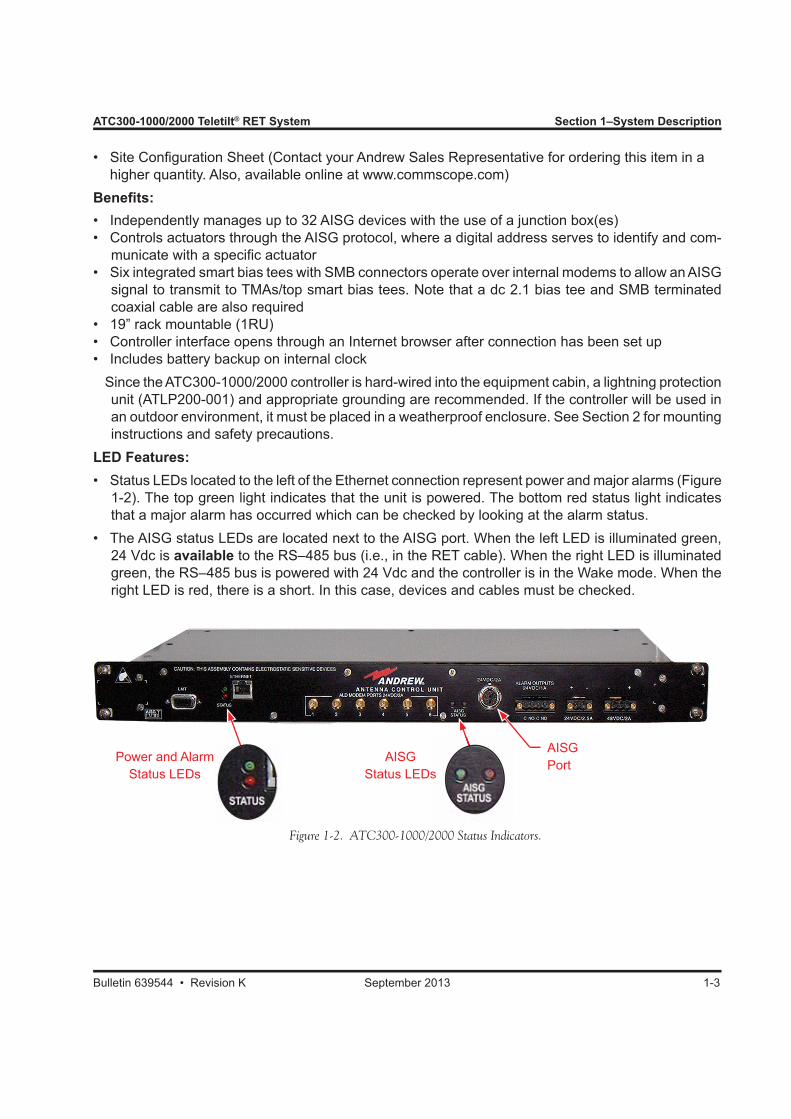
Figure 1-2. ATC300-1000/2000 Status Indicators.
Power and Alarm Status LEDs
AISGStatus LEDs
AISGPort
s
• Site Configuration Sheet (Contact your Andrew Sales Representative for ordering this item in a higher quantity. Also, available online at www.commscope.com)Benefits:• Independently manages up to 32 AISG devices with the use of a junction box(es)• Controls actuators through the AISG protocol, where a digital address serves to identify and com-
municate with a specific actuator• Six integrated smart bias tees with SMB connectors operate over internal modems to allow an AISG
signal to transmit to TMAs/top smart bias tees. Note that a dc 2.1 bias tee and SMB terminated coaxial cable are also required
• 19” rack mountable (1RU)• Controller interface opens through an Internet browser after connection has been set up• Includes battery backup on internal clock Since the ATC300-1000/2000 controller is hard-wired into the equipment cabin, a lightning protection
unit (ATLP200-001) and appropriate grounding are recommended. If the controller will be used in an outdoor environment, it must be placed in a weatherproof enclosure. See Section 2 for mounting instructions and safety precautions.
LED Features:• Status LEDs located to the left of the Ethernet connection represent power and major alarms (Figure
1-2). The top green light indicates that the unit is powered. The bottom red status light indicates that a major alarm has occurred which can be checked by looking at the alarm status.
• The AISG status LEDs are located next to the AISG port. When the left LED is illuminated green, 24 Vdc is available to the RS–485 bus (i.e., in the RET cable). When the right LED is illuminated green, the RS–485 bus is powered with 24 Vdc and the controller is in the Wake mode. When the right LED is red, there is a short. In this case, devices and cables must be checked.
Section 1–System Description ATC300-1000/2000 Teletilt® RET System
1-4 September 2013 Bulletin 639544 • Revision K
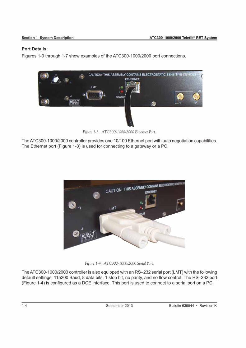
Port Details:Figures 1-3 through 1-7 show examples of the ATC300-1000/2000 port connections.
Figure 1-3. ATC300-1000/2000 Ethernet Port.
The ATC300-1000/2000 controller provides one 10/100 Ethernet port with auto negotiation capabilities. The Ethernet port (Figure 1-3) is used for connecting to a gateway or a PC.
Figure 1-4. ATC300-1000/2000 Serial Port.
The ATC300-1000/2000 controller is also equipped with an RS–232 serial port (LMT) with the following default settings: 115200 Baud, 8 data bits, 1 stop bit, no parity, and no flow control. The RS–232 port (Figure 1-4) is configured as a DCE interface. This port is used to connect to a serial port on a PC.
ATC300-1000/2000 Teletilt® RET System Section 1–System Description
Bulletin 639544 • Revision K September 2013 1-5
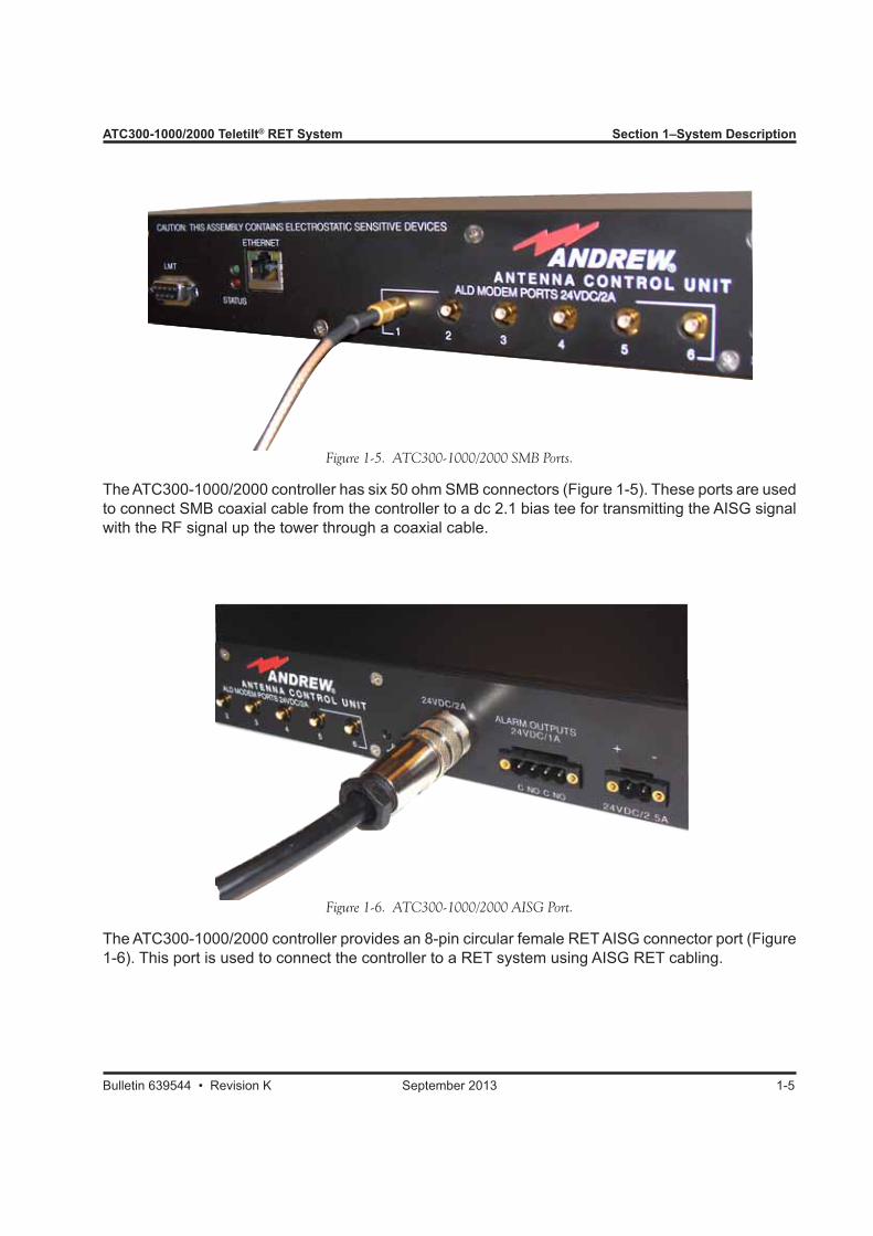
Figure 1-5. ATC300-1000/2000 SMB Ports.
The ATC300-1000/2000 controller has six 50 ohm SMB connectors (Figure 1-5). These ports are used to connect SMB coaxial cable from the controller to a dc 2.1 bias tee for transmitting the AISG signal with the RF signal up the tower through a coaxial cable.
Figure 1-6. ATC300-1000/2000 AISG Port.
The ATC300-1000/2000 controller provides an 8-pin circular female RET AISG connector port (Figure 1-6). This port is used to connect the controller to a RET system using AISG RET cabling.
Section 1–System Description ATC300-1000/2000 Teletilt® RET System
1-6 September 2013 Bulletin 639544 • Revision K
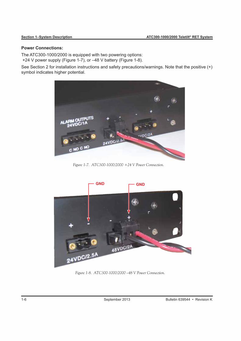
Power Connections:The ATC300-1000/2000 is equipped with two powering options: +24 V power supply (Figure 1-7), or –48 V battery (Figure 1-8). See Section 2 for installation instructions and safety precautions/warnings. Note that the positive (+) symbol indicates higher potential.
Figure 1-7. ATC300-1000/2000 +24 V Power Connection.
Figure 1-8. ATC300-1000/2000 –48 V Power Connection.
GND GND
ATC300-1000/2000 Teletilt® RET System Section 1–System Description
Bulletin 639544 • Revision K September 2013 1-7
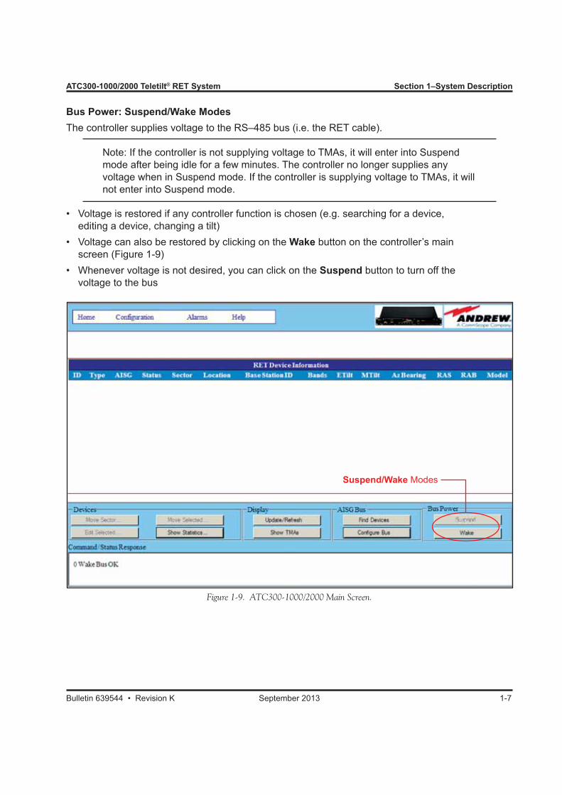
Bus Power: Suspend/Wake ModesThe controller supplies voltage to the RS–485 bus (i.e. the RET cable).
Note: If the controller is not supplying voltage to TMAs, it will enter into Suspend mode after being idle for a few minutes. The controller no longer supplies any voltage when in Suspend mode. If the controller is supplying voltage to TMAs, it will not enter into Suspend mode.
• Voltage is restored if any controller function is chosen (e.g. searching for a device, editing a device, changing a tilt)• Voltage can also be restored by clicking on the Wake button on the controller’s main screen (Figure 1-9)• Whenever voltage is not desired, you can click on the Suspend button to turn off the voltage to the bus
Figure 1-9. ATC300-1000/2000 Main Screen.
Suspend/Wake Modes

Section 1–System Description ATC300-1000/2000 Teletilt® RET System
1-8 September 2013 Bulletin 639544 • Revision K
Alarm Outputs:The ATC300-1000/2000 controller has two relay outputs for conveying alarm conditions. These con-tacts are specified for +24 Vdc maximum voltage with a maximum load of 1 Amp. The connector is equipped with a 4-pin terminal block (Figure 1-10). Pin assignments are shown in Table 1-1.
Pin Number Pin Name Description1 C-1 Relay-1 Center contact2 NO-1 Relay-1 Normally-open contact3 C-2 Relay-2 Center contact4 NO-2 Relay-2 Normally-open contact
Table 1-1. ATC300-1000/2000 Alarm Output Pin Assignments.
Pins 1 and 2, shown to the left in Figure 1-10, are used for major alarms. These will close in the event there is a major alarm and will cause the Alarm LED to light up. Pins 3 and 4, shown to the right in Figure 1-10, are used for minor alarms. See Appendix D for definition of alarm conditions.
1.2.1 Modem Port Isolation (ATC300-2000 only)The ATC300-2000 hardware provides port isolation from overcurrent conditions. The unit has three modem ports, each providing RS485 capability to a pair of external SMB ports. The AISG port is also isolated from the modem ports. If a short is detected on the AISG bus, the ATC300-2000 will remove power to only the affected modem or AISG port, leaving the other ports operational.
Figure 1-10. ATC300-1000/2000 Alarm Outputs.
Remove the 4-pin connector from the controller chassis and connect the alarm outputs as required by the alarming setting at the installation site.
ATC300-1000/2000 Teletilt® RET System Section 1–System Description
Bulletin 639544 • Revision K September 2013 1-9
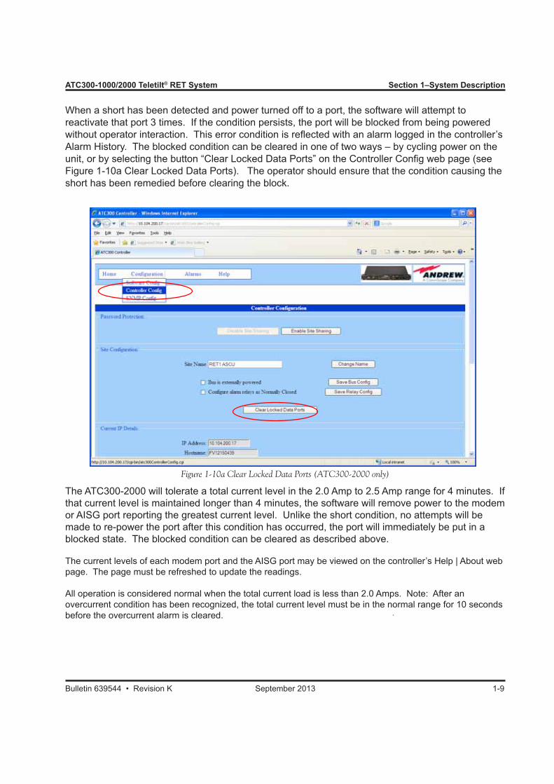
When a short has been detected and power turned off to a port, the software will attempt to reactivate that port 3 times. If the condition persists, the port will be blocked from being powered without operator interaction. This error condition is reflected with an alarm logged in the controller’s Alarm History. The blocked condition can be cleared in one of two ways – by cycling power on the unit, or by selecting the button “Clear Locked Data Ports” on the Controller Config web page (see Figure 1-10a Clear Locked Data Ports). The operator should ensure that the condition causing the short has been remedied before clearing the block.
Figure 1-10a Clear Locked Data Ports (ATC300-2000 only)
The ATC300-2000 will tolerate a total current level in the 2.0 Amp to 2.5 Amp range for 4 minutes. If that current level is maintained longer than 4 minutes, the software will remove power to the modem or AISG port reporting the greatest current level. Unlike the short condition, no attempts will be made to re-power the port after this condition has occurred, the port will immediately be put in a blocked state. The blocked condition can be cleared as described above.
The current levels of each modem port and the AISG port may be viewed on the controller’s Help | About web page. The page must be refreshed to update the readings.
All operation is considered normal when the total current load is less than 2.0 Amps. Note: After an overcurrent condition has been recognized, the total current level must be in the normal range for 10 seconds before the overcurrent alarm is cleared.

Section 1–System Description ATC300-1000/2000 Teletilt® RET System
1-10 September 2013 Bulletin 639544 • Revision K
1.3 Actuator (Motor Drive)The ATM200 series actuator (motor drive), shown in Figure 1-11, houses a brushless stepper motor system. This system permits the actuator to transmit data to the controller identifying its position and angular tilt setting, as well as receive data from the controller for angular tilt adjustments to be made. The brushless approach was adopted for high reliability and low EMI.Features/benefits include:• Actuator can be installed on Teletilt compat-
ible variable electrical downtilt antennas that are already in service
• Antenna models are available with the actuator factory installed
• A single actuator adjusts both vertical and dual polarized single band antennas. Tilt adjustments are made simultaneously to both +45°/–45° polarizations
Dual band or quad port antennas (possess-ing two independently adjustable variable downtilts) require two actuators—one for each downtilt adjuster. Likewise, three actuators would be required for a tri band or six port antenna
• Actuator is enclosed in a gasket-sealed, weather resistant container. Container provides a drain hole to allow drainage of condensed moisture
• Adjustments are complete in less than 15 seconds from the time the command is received• Weighs less than 0.3 kg; operating temperature range is –40° to +70° C
Andrew Solutions recommends that the transmit RF power be turned off when working around the antenna to field retrofit an actuator, and that all applicable safety procedures be followed. Bulletin 639552, Field Replacement of Factory Installed Actuators, provides complete instructions.
• AISG Reset Capability The ATC 300-1000/2000 and ATC 200-1000 controller supports two AISG modes, simultaneously,
on the same RET system. Andrew ATM200-002 actuators are factory set to operate in AISG 1.1 mode, but can be switched to operate in AISG 2.0 using the controller’s AISG Control Tools (Sec-tion 11.5).
Figure 1-11. ATM200 Actuator (Motor Drive) Showing Input Connector.
Male Input Port

ATC300-1000/2000 Teletilt® RET System Section 1–System Description
Bulletin 639544 • Revision K September 2013 1-11
1.4 Junction BoxesJunction boxes are used to join up to 32 AISG RET (remote electrical control) devices (antennas with actuators and TMAs) to the controller. These units also divide data and power on the main control cable feeding into the RET devices.Features/benefits include: • The ATJB200-A01-004 (four-way, shown in Figure
1-12) and ATJB200-A01-007 (seven-way, shown in 1-13) junction boxes are designed for linking multiple RET devices into the RET system.
• Both ATJB200-A01-004 and ATJB200-A01-007 junction boxes are pipe or wall/flat surface mount-able with mounting brackets included.
• Junction boxes provide additional lightning protec-tion to the RET system (ATGK-COMP grounding kit, included). If a junction box will not be used at the top of the RET system, it is recommended that an additional lightning protection unit be installed at the tower top.
1.5 Lightning Protection UnitLightning protection unit, ATLP200-001, is designed to provide added protection to all ATC300-1000/2000 system equipment (controller, actuators, junction boxes). See Figure 1-14. Features/benefits include:• Designed to withstand a short circuit current level
of 10/350 μs, 0.6kA (line to ground) (per IEC 61312-1 standard)
• Equipped with a grounding nut; must be grounded (ATGK-COMP grounding kit)
• 8–pin male and female interfaces to feed data and power from the controller to the first junction box or actuator.
• Pipe or wall/flat surface mountable with mounting brackets included.
• ATGK-COMP grounding kit, included.
Figure 1-12. ATJB200-A01-004 Four-Way Junction Box.
Figure 1-13. ATJB200-A01-007 Seven-Way Junction Box.
Figure 1-14. ATLP200-001 Lightning Protection Unit.
Section 1–System Description ATC300-1000/2000 Teletilt® RET System
1-12 September 2013 Bulletin 639544 • Revision K
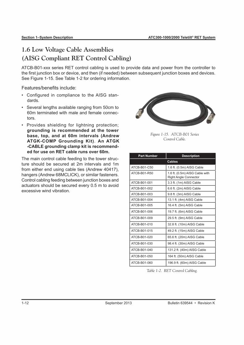
1.6 Low Voltage Cable Assemblies(AISG Compliant RET Control Cabling)ATCB-B01-xxx series RET control cabling is used to provide data and power from the controller to the first junction box or device, and then (if needed) between subsequent junction boxes and devices. See Figure 1-15. See Table 1-2 for ordering information.
Features/benefits include:• Configured in compliance to the AISG stan-
dards.• Several lengths available ranging from 50cm to
60m terminated with male and female connec-tors.
• Provides shielding for lightning protection; grounding is recommended at the tower base, top, and at 60m intervals (Andrew ATGK-COMP Grounding Kit). An ATGK -CABLE grounding clamp kit is recommend- ed for use on RET cable runs over 60m.
The main control cable feeding to the tower struc-ture should be secured at 2m intervals and 1m from either end using cable ties (Andrew 40417), hangers (Andrew 68MCLICK), or similar fasteners. Control cabling feeding between junction boxes and actuators should be secured every 0.5 m to avoid excessive wind vibration.
Figure 1-15. ATCB-B01 Series Control Cable.
Part Number Description
Cables
ATCB-B01-C50 1.6 ft. (0.5m) AISG Cable
ATCB-B01-R50 1.6 ft. (0.5m) AISG Cable with Right Angle Connector
ATCB-B01-001 3.3 ft. (1m) AISG Cable
ATCB-B01-002 6.6 ft. (2m) AISG Cable
ATCB-B01-003 9.8 ft. (3m) AISG Cable
ATCB-B01-004 13.1 ft. (4m) AISG Cable
ATCB-B01-005 16.4 ft. (5m) AISG Cable
ATCB-B01-006 19.7 ft. (6m) AISG Cable
ATCB-B01-009 29.5 ft. (9m) AISG Cable
ATCB-B01-010 32.8 ft. (10m) AISG Cable
ATCB-B01-015 49.2 ft. (15m) AISG Cable
ATCB-B01-020 65.6 ft. (20m) AISG Cable
ATCB-B01-030 98.4 ft. (30m) AISG Cable
ATCB-B01-040 131.2 ft. (40m) AISG Cable
ATCB-B01-050 164 ft. (50m) AISG Cable
ATCB-B01-060 196.9 ft. (60m) AISG Cable
Table 1-2. RET Control Cabling.

ATC300-1000/2000 Teletilt® RET System Section 1–System Description
Bulletin 639544 • Revision K September 2013 1-13
This page intentionally left blank

Section 2Installation Instructions and Safety Precautions
2.0 Section OverviewThis section covers installation procedures for mounting and grounding the ATC300-1000/2000 con-troller chassis, as well as safety precautions.
2.1 AbbreviationsAWG American Wire Gauge
2.2 Installation PreparationsWarnings:• This equipment should only be installed by trained personnel.• Do not connect or disconnect cables during lightning activity.
Preparation:• Remove the ATC300-1000/2000 controller from the packaging container (also see ESD precau-
tions in the introduction of this document).• Verify availability of power, either –48 V battery or +24 V power supply.
Tools and Parts:• 14–AWG multi-strand copper wire for power connection, using color coding as specified at the
installation site.• 10–AWG multi-strand copper wire, using appropriate color coding as specified at the installation
site.• Ring-torque terminal for a 1/4” stud.• Crimping tool for ring-torque terminal.• Four mounting screws to mount the controller chassis onto the rack.• 6” adjustable wrench.• 1/8” flat-blade screwdriver.• Wire stripper.
Bulletin 639544 • Revision K September 2013 2-1
Section 2–Installation Instructions and Safety Precautions ATC300-1000/2000 Teletilt® RET System
2-2 September 2013 Bulletin 639544 • Revision K
Figure 2-1. Rack Mounted ATC300-1000/2000 Controller.
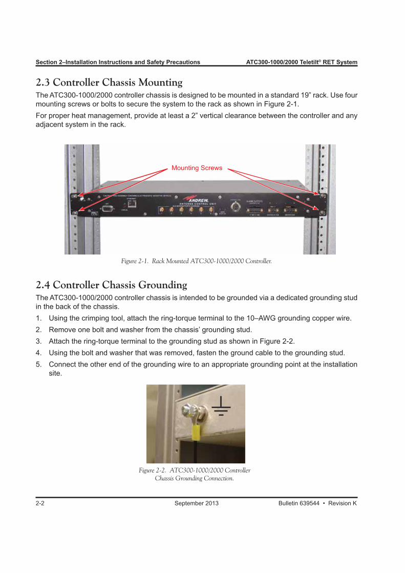
2.3 Controller Chassis MountingThe ATC300-1000/2000 controller chassis is designed to be mounted in a standard 19” rack. Use four mounting screws or bolts to secure the system to the rack as shown in Figure 2-1.For proper heat management, provide at least a 2” vertical clearance between the controller and any adjacent system in the rack.
Mounting Screws
2.4 Controller Chassis GroundingThe ATC300-1000/2000 controller chassis is intended to be grounded via a dedicated grounding stud in the back of the chassis.1. Using the crimping tool, attach the ring-torque terminal to the 10–AWG grounding copper wire.2. Remove one bolt and washer from the chassis’ grounding stud.3. Attach the ring-torque terminal to the grounding stud as shown in Figure 2-2.4. Using the bolt and washer that was removed, fasten the ground cable to the grounding stud.5. Connect the other end of the grounding wire to an appropriate grounding point at the installation
site.
Figure 2-2. ATC300-1000/2000 Controller Chassis Grounding Connection.
ATC300-1000/2000 Teletilt® RET System Section 2–Installation Instructions and Safety Precautions
Bulletin 639544 • Revision K September 2013 2-3
2.5 Controller Chassis PowerThe ATC300-1000/2000 controller chassis provides two powering options, –48 V battery or +24 V power supply. The controller needs only one of these power options to operate.Input voltage operating ranges:+24 Vdc Supply: +19 Vdc to +30 Vdc–48 Vdc Supply: –36 Vdc to –72 VdcEnsure that the operating voltage meets the range specified above.
Warning! To avoid shocking hazard, open the circuit breaker protecting the power distribution for the mounting rack.
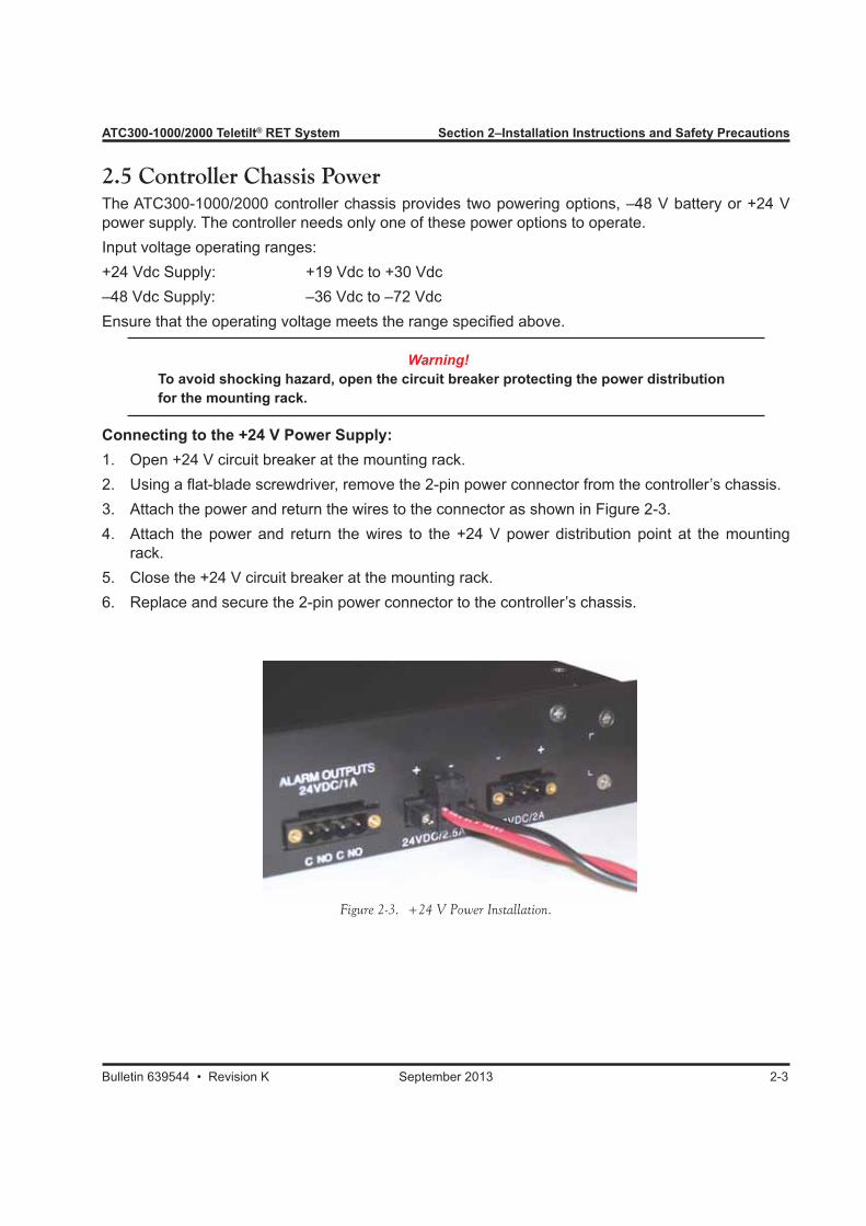
Connecting to the +24 V Power Supply:1. Open +24 V circuit breaker at the mounting rack.2. Using a flat-blade screwdriver, remove the 2-pin power connector from the controller’s chassis.3. Attach the power and return the wires to the connector as shown in Figure 2-3.4. Attach the power and return the wires to the +24 V power distribution point at the mounting
rack.5. Close the +24 V circuit breaker at the mounting rack.6. Replace and secure the 2-pin power connector to the controller’s chassis.
Figure 2-3. +24 V Power Installation.
Section 2–Installation Instructions and Safety Precautions ATC300-1000/2000 Teletilt® RET System
2-4 September 2013 Bulletin 639544 • Revision K
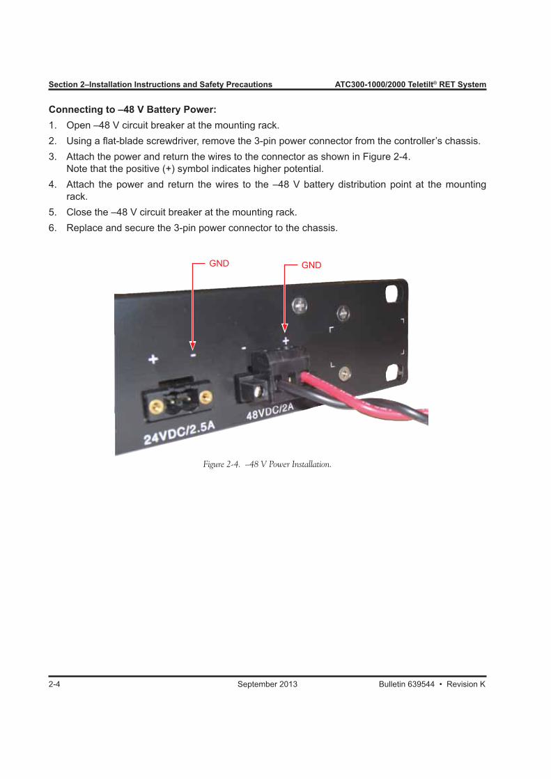
Connecting to –48 V Battery Power:1. Open –48 V circuit breaker at the mounting rack.2. Using a flat-blade screwdriver, remove the 3-pin power connector from the controller’s chassis.3. Attach the power and return the wires to the connector as shown in Figure 2-4. Note that the positive (+) symbol indicates higher potential.4. Attach the power and return the wires to the –48 V battery distribution point at the mounting
rack.5. Close the –48 V circuit breaker at the mounting rack.6. Replace and secure the 3-pin power connector to the chassis.
Figure 2-4. –48 V Power Installation.
GND GND
Bulletin 639544 • Revision K September 2013 3-1
Section 3Changing IP Settings on the Local Computer Using the IP Config Tool
3.0 Section Overview• In order for a local computer to gain access to the ATC300-1000/2000 or ATC200-1000 controller,
settings will need to be configured on the computer. The IP Config Tool provides a user friendly environment for changing the local computer’s IP settings.
See Appendix B for understanding IP addressing.• The IP Config Tool is compatible for use on computers operating in the English lan-
guage using Windows® 2000 or Windows® XP. At the time of this publication, it has not been determined if earlier versions of Windows® are compatible with the IP Config Tool. See Appendix B when setting an IP address for Windows Vista operating systems.
• After connection to the controller is no longer needed, the original IP settings for the local computer will need to be restored in order for it to regain communication with a company LAN or other Ethernet connection. The IP Config Tool automatically restores the original IP settings to the local computer when the application tool is closed.
• IP configurations made to the local computer for access to the controller may be backed up and later restored/used for future access.
3.1 Downloading/Extracting the IP Config Tool Zip File1. The IP Config Tool zip file can be downloaded from the Commscope web site. From
the Andrew Products tab on www.commscope.com, click on Antennas→Teletilt RET System→Downloads→RET Controller Software and Firmware. Scroll down to the ATC300-1000/2000 Rack Mount Controller image, and save the IP Config Tool to the computer desktop that will be accessing the controller.
2. After the download is complete, double-click on the zipped ipconfig tool file to extract the ipconfigtool.exe file to the local computer’s desktop. The ipconfigtool.exe file will be used to install the IP Config Tool to the computer.
Microsoft, Encarta, MSN, and Windows are either registered trademarks or trademarks of Microsoft Corporation in the United States and/or other countries.
Section 3–Changing IP Settings on the Local PC Using the IP Config Tool ATC300-1000/2000 Teletilt® RET System
3-2 September 2013 Bulletin 639544 • Revision K
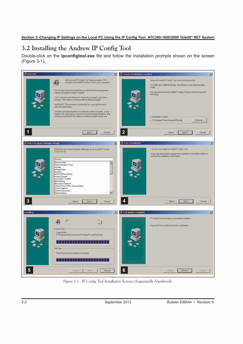
3.2 Installing the Andrew IP Config ToolDouble-click on the ipconfigtool.exe file and follow the installation prompts shown on the screen (Figure 3-1).
Figure 3-1. IP Config Tool Installation Screens (Sequentially Numbered).
3
6
2
5
1
4
ATC300-1000/2000 Teletilt® RET System Section 3–Changing IP Settings on the Local PC Using the IP Config Tool
Bulletin 639544 • Revision K September 2013 3-3
Figure 3-3. Initial IP Configuration Tool Screen.
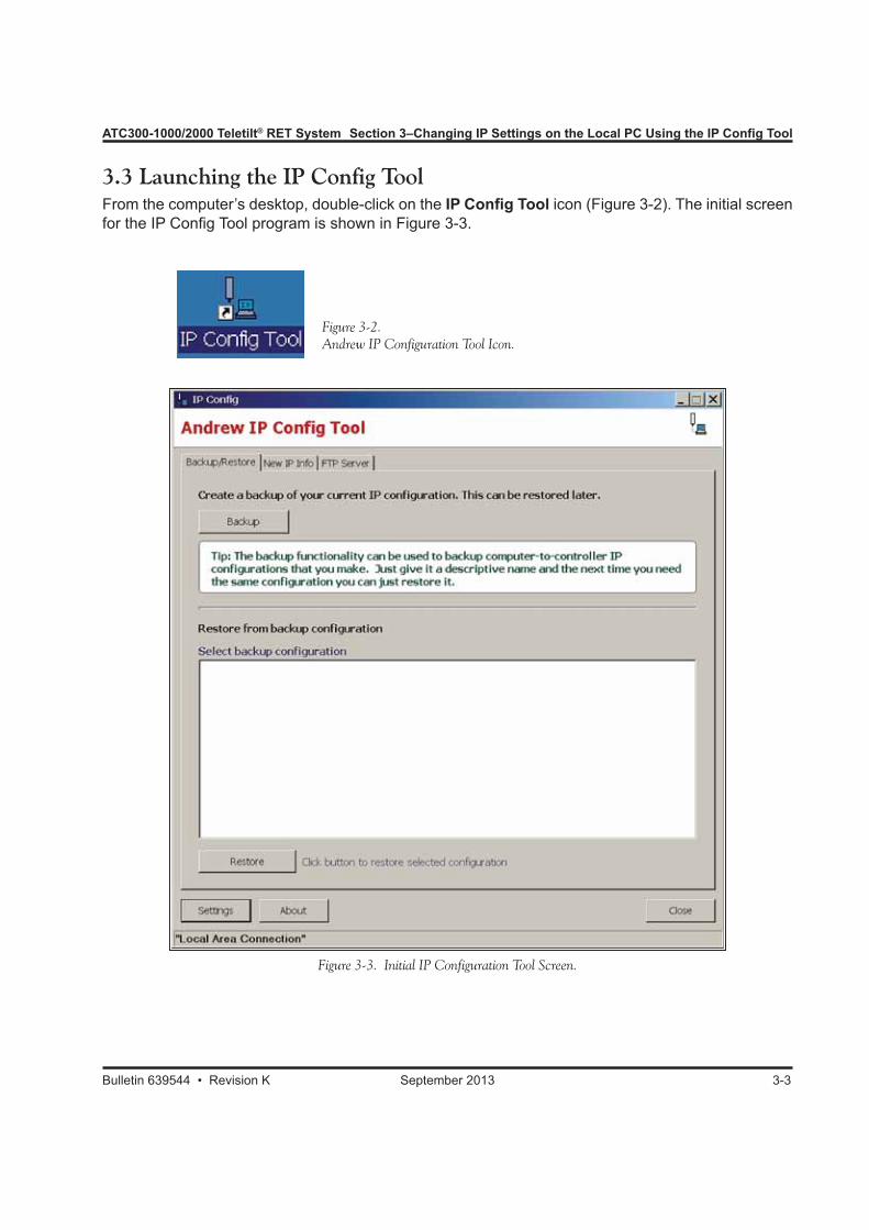
Figure 3-2. Andrew IP Configuration Tool Icon.
3.3 Launching the IP Config ToolFrom the computer’s desktop, double-click on the IP Config Tool icon (Figure 3-2). The initial screen for the IP Config Tool program is shown in Figure 3-3.
Section 3–Changing IP Settings on the Local PC Using the IP Config Tool ATC300-1000/2000 Teletilt® RET System
3-4 September 2013 Bulletin 639544 • Revision K
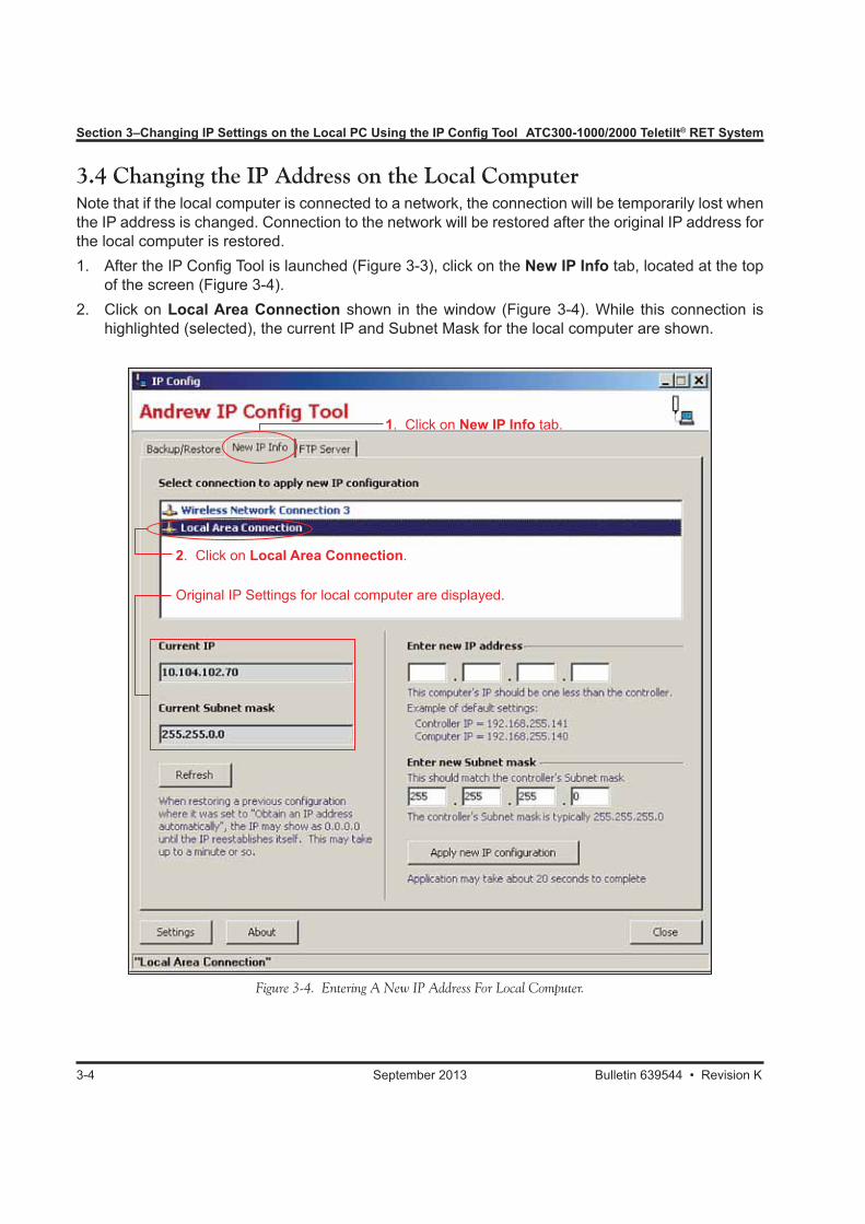
3.4 Changing the IP Address on the Local ComputerNote that if the local computer is connected to a network, the connection will be temporarily lost when the IP address is changed. Connection to the network will be restored after the original IP address for the local computer is restored.1. After the IP Config Tool is launched (Figure 3-3), click on the New IP Info tab, located at the top
of the screen (Figure 3-4).2. Click on Local Area Connection shown in the window (Figure 3-4). While this connection is
highlighted (selected), the current IP and Subnet Mask for the local computer are shown.
Figure 3-4. Entering A New IP Address For Local Computer.
2. Click on Local Area Connection.
1. Click on New IP Info tab.
Original IP Settings for local computer are displayed.
ATC300-1000/2000 Teletilt® RET System Section 3–Changing IP Settings on the Local PC Using the IP Config Tool
Bulletin 639544 • Revision K September 2013 3-5
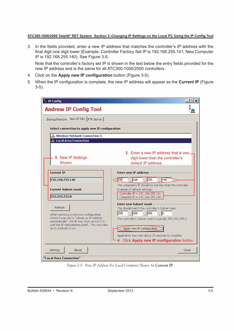
3. In the fields provided, enter a new IP address that matches the controller’s IP address with the final digit one digit lower (Example: Controller Factory Set IP is 192.168.255.141; New Computer IP is 192.168.255.140). See Figure 3-5.
Note that the controller’s factory set IP is shown in the text below the entry fields provided for the new IP address and is the same for all ATC300-1000/2000 controllers.
4. Click on the Apply new IP configuration button (Figure 3-5).5. When the IP configuration is complete, the new IP address will appear as the Current IP (Figure
3-5).
Figure 3-5. New IP Address For Local Computer Shown As Current IP.
5. New IP Settings Shown
3. Enter a new IP address that is one digit lower than the controller’s default IP address.
4. Click Apply new IP configuration button.
Section 3–Changing IP Settings on the Local PC Using the IP Config Tool ATC300-1000/2000 Teletilt® RET System
3-6 September 2013 Bulletin 639544 • Revision K
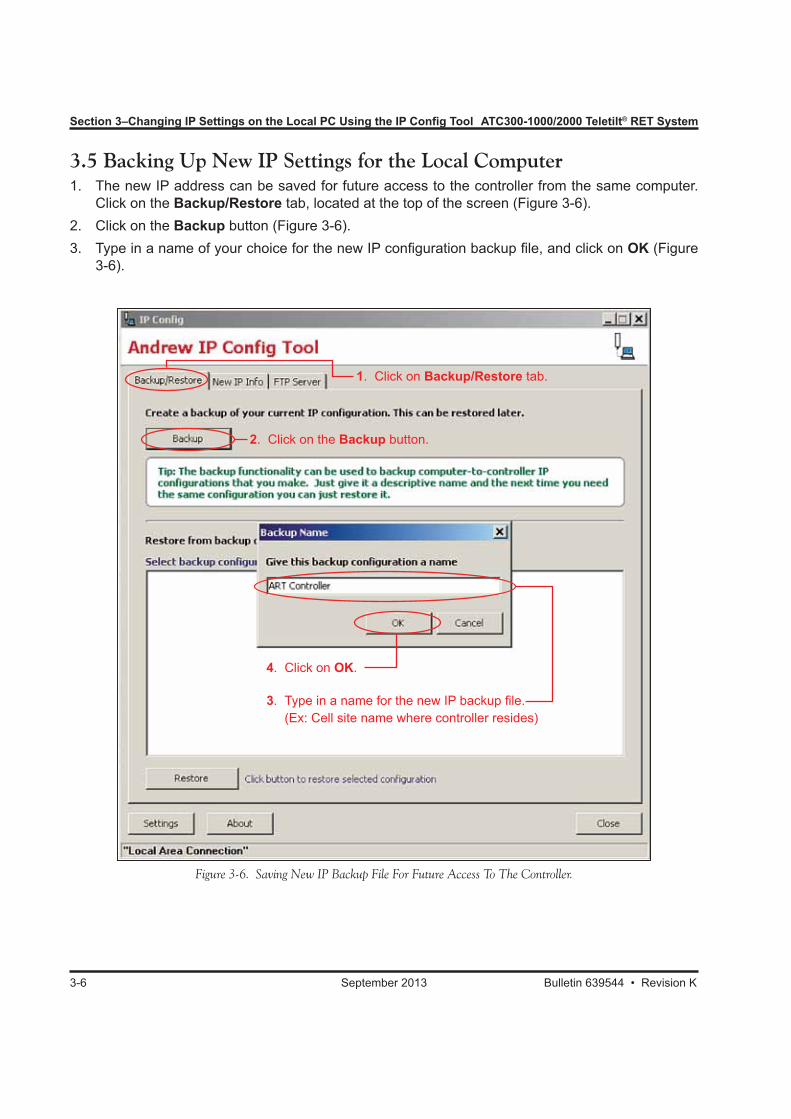
3.5 Backing Up New IP Settings for the Local Computer1. The new IP address can be saved for future access to the controller from the same computer.
Click on the Backup/Restore tab, located at the top of the screen (Figure 3-6). 2. Click on the Backup button (Figure 3-6).3. Type in a name of your choice for the new IP configuration backup file, and click on OK (Figure
3-6).
Figure 3-6. Saving New IP Backup File For Future Access To The Controller.
1. Click on Backup/Restore tab.
2. Click on the Backup button.
3. Type in a name for the new IP backup file. (Ex: Cell site name where controller resides)
4. Click on OK.
ATC300-1000/2000 Teletilt® RET System Section 3–Changing IP Settings on the Local PC Using the IP Config Tool
Bulletin 639544 • Revision K September 2013 3-7
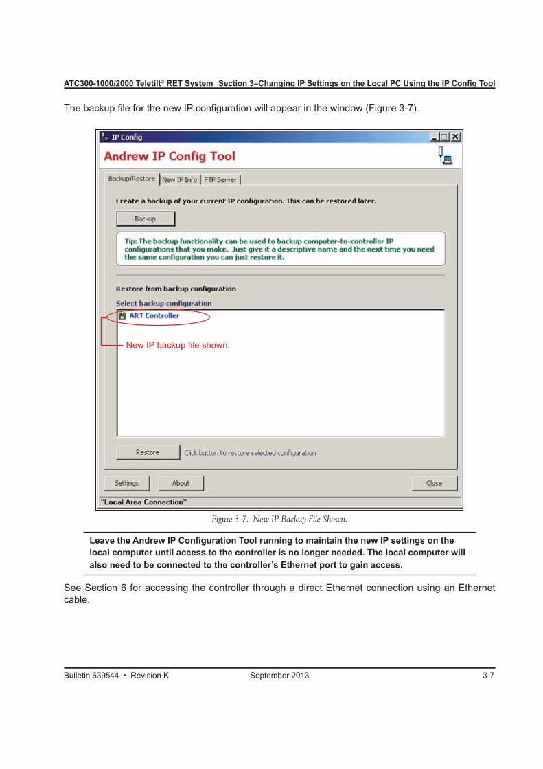
The backup file for the new IP configuration will appear in the window (Figure 3-7).
Figure 3-7. New IP Backup File Shown.
New IP backup file shown.
Leave the Andrew IP Configuration Tool running to maintain the new IP settings on the local computer until access to the controller is no longer needed. The local computer will also need to be connected to the controller’s Ethernet port to gain access.
See Section 6 for accessing the controller through a direct Ethernet connection using an Ethernet cable.
Section 3–Changing IP Settings on the Local PC Using the IP Config Tool ATC300-1000/2000 Teletilt® RET System
3-8 September 2013 Bulletin 639544 • Revision K
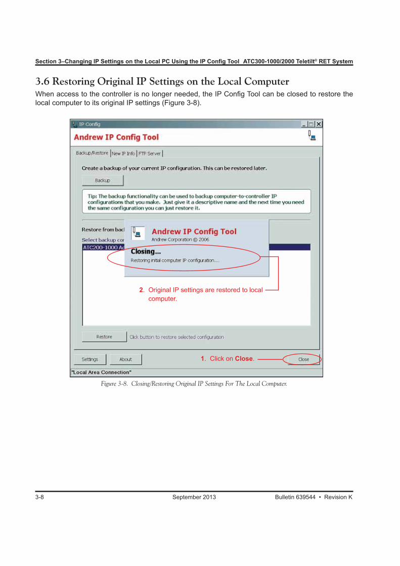
Figure 3-8. Closing/Restoring Original IP Settings For The Local Computer.
3.6 Restoring Original IP Settings on the Local ComputerWhen access to the controller is no longer needed, the IP Config Tool can be closed to restore the local computer to its original IP settings (Figure 3-8).
2. Original IP settings are restored to local computer.
1. Click on Close.
ATC300-1000/2000 Teletilt® RET System Section 3–Changing IP Settings on the Local PC Using the IP Config Tool
Bulletin 639544 • Revision K September 2013 3-9
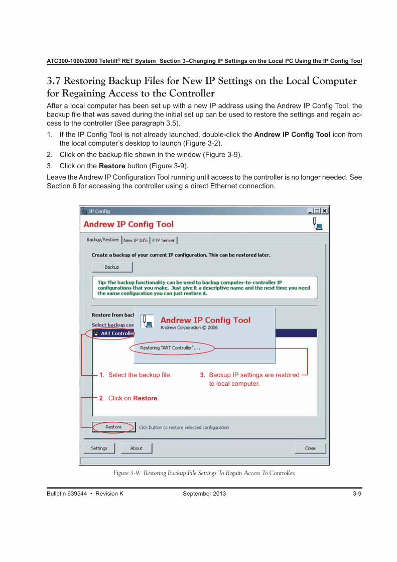
3.7 Restoring Backup Files for New IP Settings on the Local Computer for Regaining Access to the ControllerAfter a local computer has been set up with a new IP address using the Andrew IP Config Tool, the backup file that was saved during the initial set up can be used to restore the settings and regain ac-cess to the controller (See paragraph 3.5).1. If the IP Config Tool is not already launched, double-click the Andrew IP Config Tool icon from
the local computer’s desktop to launch (Figure 3-2).2. Click on the backup file shown in the window (Figure 3-9).3. Click on the Restore button (Figure 3-9).Leave the Andrew IP Configuration Tool running until access to the controller is no longer needed. See Section 6 for accessing the controller using a direct Ethernet connection.
Figure 3-9. Restoring Backup File Settings To Regain Access To Controller.
1. Select the backup file.
2. Click on Restore.
3. Backup IP settings are restored to local computer.
Section 3–Changing IP Settings on the Local PC Using the IP Config Tool ATC300-1000/2000 Teletilt® RET System
3-10 September 2013 Bulletin 639544 • Revision K
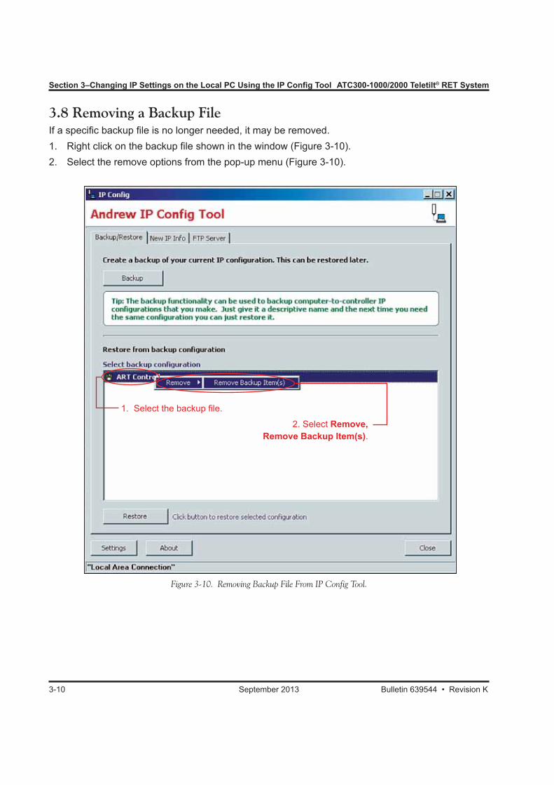
Figure 3-10. Removing Backup File From IP Config Tool.
3.8 Removing a Backup FileIf a specific backup file is no longer needed, it may be removed. 1. Right click on the backup file shown in the window (Figure 3-10).2. Select the remove options from the pop-up menu (Figure 3-10).
1. Select the backup file.
2. Select Remove, Remove Backup Item(s).
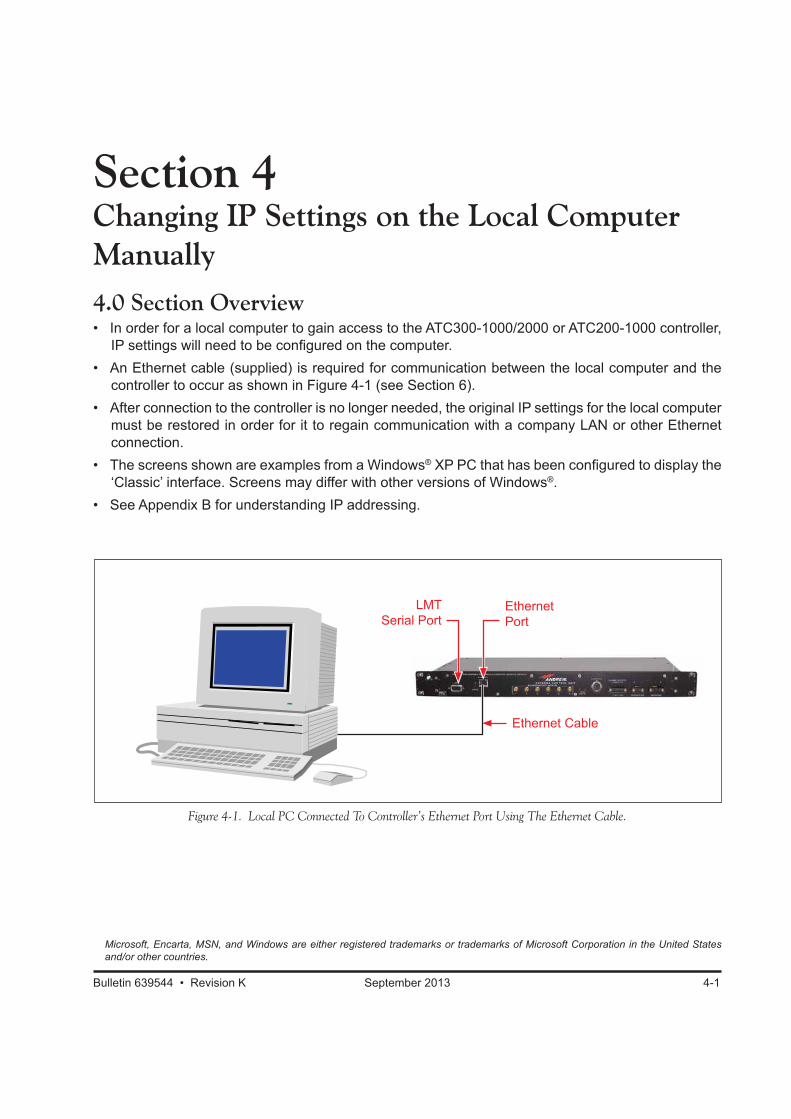
Section 4Changing IP Settings on the Local Computer Manually4.0 Section Overview• In order for a local computer to gain access to the ATC300-1000/2000 or ATC200-1000 controller,
IP settings will need to be configured on the computer.• An Ethernet cable (supplied) is required for communication between the local computer and the
controller to occur as shown in Figure 4-1 (see Section 6).• After connection to the controller is no longer needed, the original IP settings for the local computer
must be restored in order for it to regain communication with a company LAN or other Ethernet connection.
• The screens shown are examples from a Windows® XP PC that has been configured to display the ‘Classic’ interface. Screens may differ with other versions of Windows®.
• See Appendix B for understanding IP addressing.
Bulletin 639544 • Revision K September 2013 4-1
Figure 4-1. Local PC Connected To Controller’s Ethernet Port Using The Ethernet Cable.
Microsoft, Encarta, MSN, and Windows are either registered trademarks or trademarks of Microsoft Corporation in the United States and/or other countries.
LMT Serial Port
Ethernet Port
Ethernet Cable
Section 4–Changing IP Settings on the Local Computer Manually ATC300-1000/2000 Teletilt® RET System
4-2 September 2013 Bulletin 639544 • Revision K
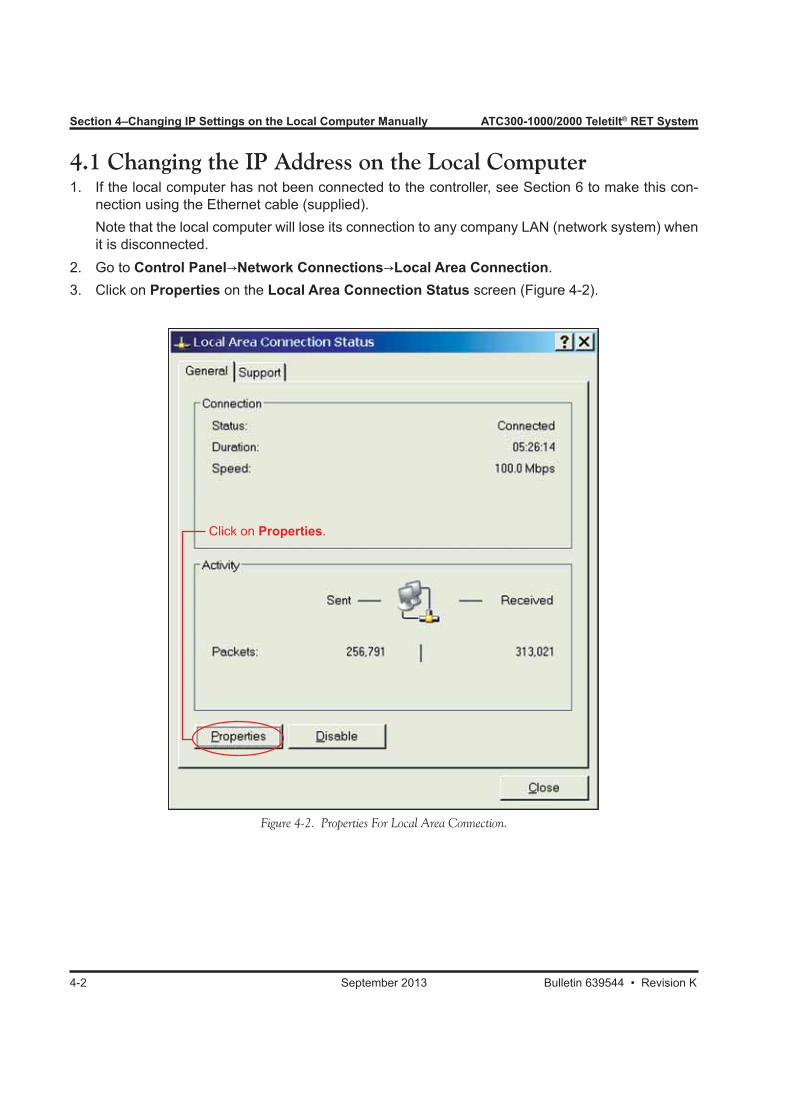
4.1 Changing the IP Address on the Local Computer1. If the local computer has not been connected to the controller, see Section 6 to make this con-
nection using the Ethernet cable (supplied). Note that the local computer will lose its connection to any company LAN (network system) when
it is disconnected.2. Go to Control Panel→Network Connections→Local Area Connection.3. Click on Properties on the Local Area Connection Status screen (Figure 4-2).
Figure 4-2. Properties For Local Area Connection.
Click on Properties.
ATC300-1000/2000 Teletilt® RET System Section 4–Changing IP Settings on the Local Computer Manually
Bulletin 639544 • Revision K September 2013 4-3
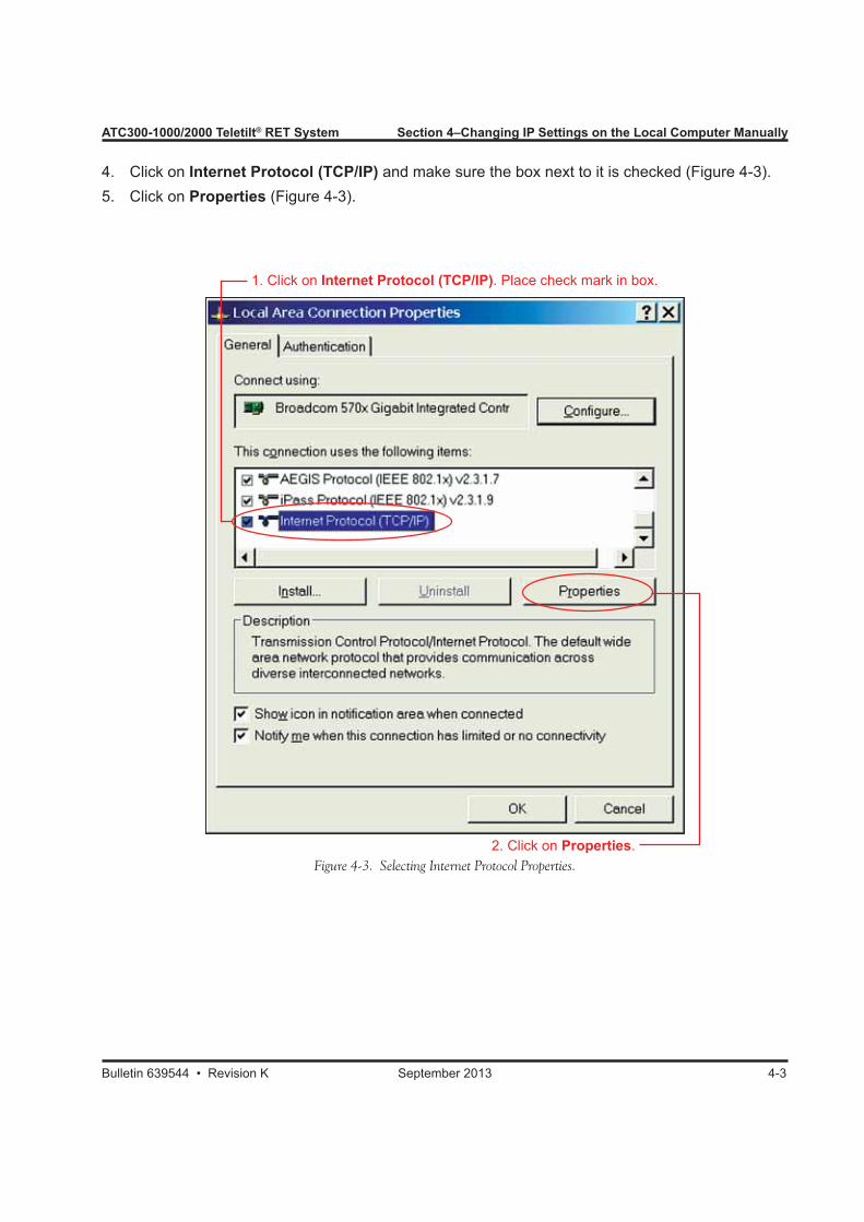
4. Click on Internet Protocol (TCP/IP) and make sure the box next to it is checked (Figure 4-3).5. Click on Properties (Figure 4-3).
Figure 4-3. Selecting Internet Protocol Properties.
1. Click on Internet Protocol (TCP/IP). Place check mark in box.
2. Click on Properties.
Section 4–Changing IP Settings on the Local Computer Manually ATC300-1000/2000 Teletilt® RET System
4-4 September 2013 Bulletin 639544 • Revision K
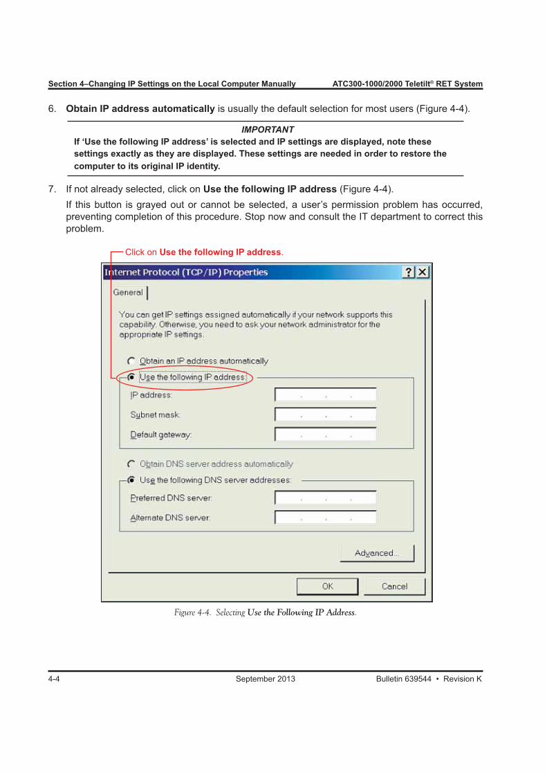
6. Obtain IP address automatically is usually the default selection for most users (Figure 4-4).
IMPORTANT If ‘Use the following IP address’ is selected and IP settings are displayed, note these settings exactly as they are displayed. These settings are needed in order to restore the computer to its original IP identity.
7. If not already selected, click on Use the following IP address (Figure 4-4). If this button is grayed out or cannot be selected, a user’s permission problem has occurred,
preventing completion of this procedure. Stop now and consult the IT department to correct this problem.
Figure 4-4. Selecting Use the Following IP Address.
Click on Use the following IP address.

ATC300-1000/2000 Teletilt® RET System Section 4–Changing IP Settings on the Local Computer Manually
Bulletin 639544 • Revision K September 2013 4-5
8. Enter an IP address that matches the controller’s IP address with the final digit one digit lower (Example: Controller Factory Set IP is 192.168.255.141; New IP is 192.168.255.140). See Figure 4–5.
9. Enter a subnet mask that matches the controller’s Netmask exactly. The controller’s default Net-mask setting is 255.255.255.0 (Figure 4-5).
10. Erase all other fields on the screen (Figure 4-5).11. Click OK (Figure 4-5).12. Close out of remaining dialog boxes. The local computer is now set up to access the controller.
Figure 4-5. Changing The IP Address On The Local Computer.
1. Enter IP address, final digit 1 lower than controller IP address.
2. Enter Subnet mask, exactly match controller Netmask setting.
3. Clear remaining fields.
4. Click on OK.

Section 4–Changing IP Settings on the Local Computer Manually ATC300-1000/2000 Teletilt® RET System
4-6 September 2013 Bulletin 639544 • Revision K
4.2 Restoring Original IP Settings on the Local ComputerWhen access to the controller is no longer needed, the IP address and subnet mask on the local com-puter must be restored to the original settings for it to reconnect to a company LAN (network system). Follow the same procedures discussed in paragraph 4.1, except enter the original IP settings that were noted before the computer was configured. If the computer was originally set to obtain an IP address automatically, click on this option and click on OK to restore a company network connection.
Section 5Obtaining IP Settings for the Controller (When IP is Unknown)
5.0 Section Overview• If IP addressing has been changed on the controller and is unknown, the IP address can be obtained
through a serial connection to the LMT port on the controller.• If the local computer is not equipped with a serial port, a USB-to-serial adapter can be used. Airlink
101 adapter has been found to be highly reliable.• The screens shown are examples from a Windows® XP PC that has been configured to display the
‘Classic’ interface. Screens may differ with other versions of Windows®.
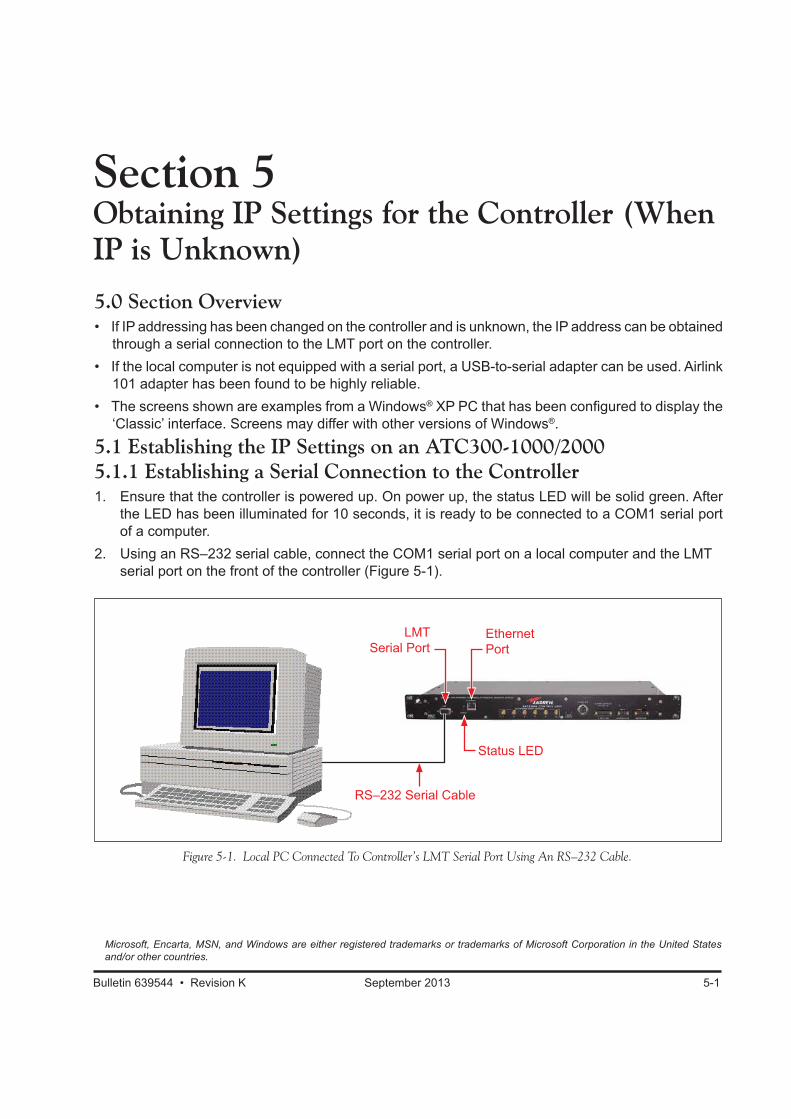
5.1 Establishing the IP Settings on an ATC300-1000/20005.1.1 Establishing a Serial Connection to the Controller1. Ensure that the controller is powered up. On power up, the status LED will be solid green. After
the LED has been illuminated for 10 seconds, it is ready to be connected to a COM1 serial port of a computer.
2. Using an RS–232 serial cable, connect the COM1 serial port on a local computer and the LMT serial port on the front of the controller (Figure 5-1).
Bulletin 639544 • Revision K September 2013 5-1
Microsoft, Encarta, MSN, and Windows are either registered trademarks or trademarks of Microsoft Corporation in the United States and/or other countries.
Figure 5-1. Local PC Connected To Controller’s LMT Serial Port Using An RS–232 Cable.
RS–232 Serial Cable
Status LED
LMT Serial Port
Ethernet Port
Section 5–Obtaining IP Settings for Controller (When IP is Unknown) ATC300-1000/2000 Teletilt® RET System
5-2 September 2013 Bulletin 639544 • Revision K
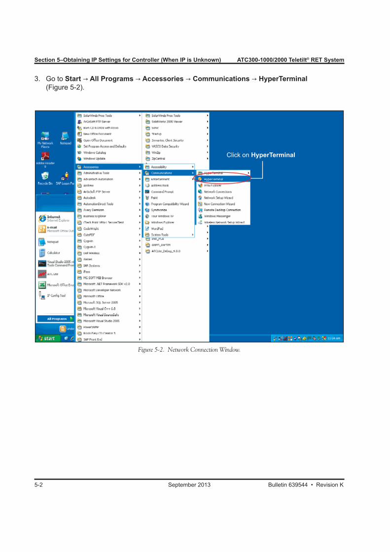
3. Go to Start → All Programs → Accessories → Communications → HyperTerminal (Figure 5-2).
Figure 5-2. Network Connection Window.
Click on HyperTerminal
ATC300-1000/2000 Teletilt® RET System Section 5–Obtaining IP Settings for Controller (When IP is Unknown)
Bulletin 639544 • Revision K September 2013 5-3
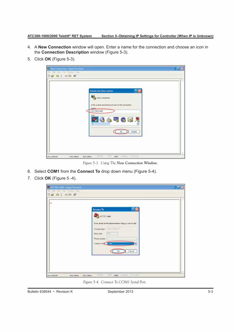
4. A New Connection window will open. Enter a name for the connection and choose an icon in the Connection Description window (Figure 5-3).5. Click OK (Figure 5-3).
Figure 5-3. Using The New Connection Window.
6. Select COM1 from the Connect To drop down menu (Figure 5-4).7. Click OK (Figure 5 -4).
Figure 5-4. Connect To COM1 Serial Port.
Section 5–Obtaining IP Settings for Controller (When IP is Unknown) ATC300-1000/2000 Teletilt® RET System
5-4 September 2013 Bulletin 639544 • Revision K
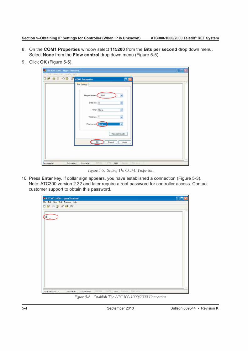
8. On the COM1 Properties window select 115200 from the Bits per second drop down menu. Select None from the Flow control drop down menu (Figure 5-5).9. Click OK (Figure 5-5).
Figure 5-5. Setting The COM1 Properties.
10. Press Enter key. If dollar sign appears, you have established a connection (Figure 5-3). Note: ATC300 version 2.32 and later require a root password for controller access. Contact customer support to obtain this password.
Figure 5-6. Establish The ATC300-1000/2000 Connection.
ATC300-1000/2000 Teletilt® RET System Section 5–Obtaining IP Settings for Controller (When IP is Unknown)
Bulletin 639544 • Revision K September 2013 5-5
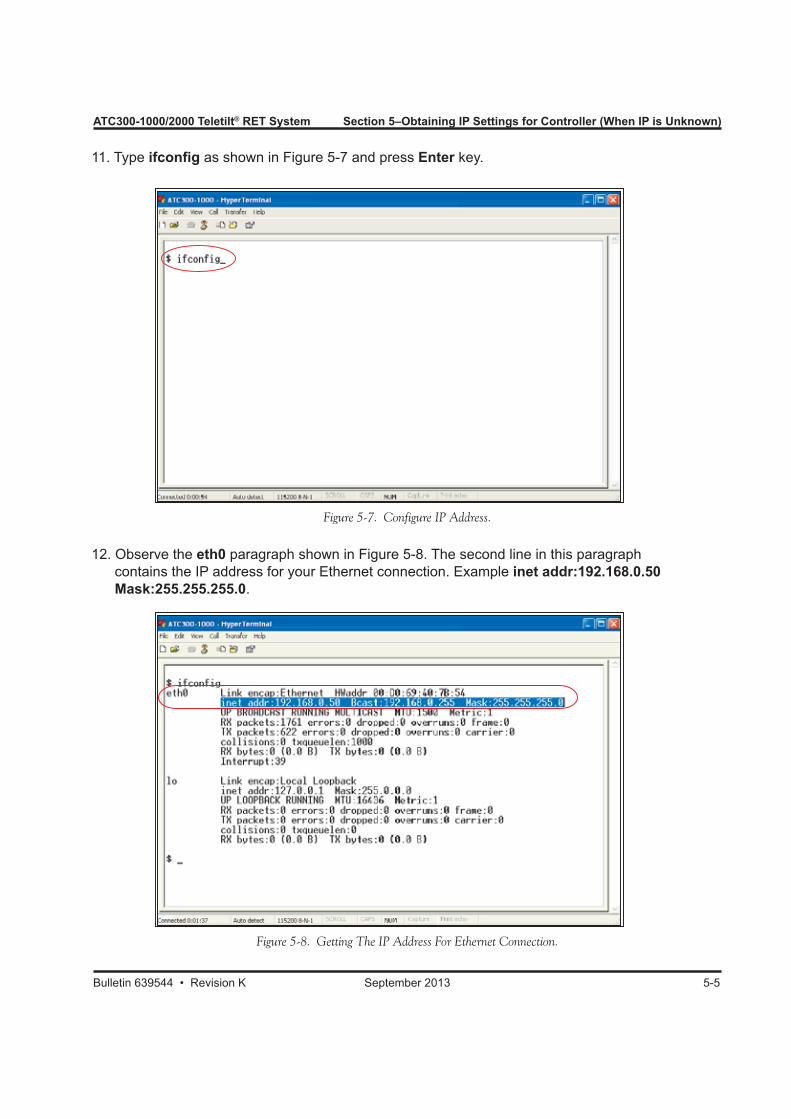
11. Type ifconfig as shown in Figure 5-7 and press Enter key.
Figure 5-7. Configure IP Address.
12. Observe the eth0 paragraph shown in Figure 5-8. The second line in this paragraph contains the IP address for your Ethernet connection. Example inet addr:192.168.0.50 Mask:255.255.255.0.
Figure 5-8. Getting The IP Address For Ethernet Connection.
Section 5–Obtaining IP Settings for Controller (When IP is Unknown) ATC300-1000/2000 Teletilt® RET System
5-6 September 2013 Bulletin 639544 • Revision K
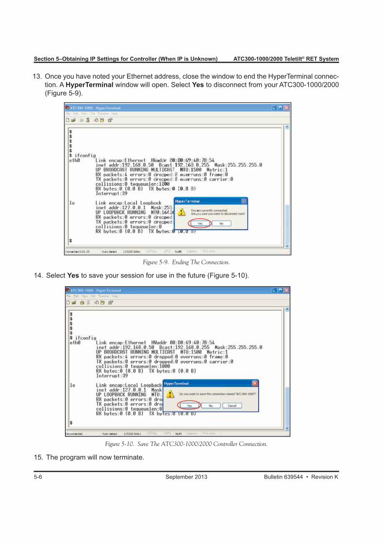
13. Once you have noted your Ethernet address, close the window to end the HyperTerminal connec-tion. A HyperTerminal window will open. Select Yes to disconnect from your ATC300-1000/2000 (Figure 5-9).
Figure 5-9. Ending The Connection.
14. Select Yes to save your session for use in the future (Figure 5-10).
15. The program will now terminate.
Figure 5-10. Save The ATC300-1000/2000 Controller Connection.
ATC300-1000/2000 Teletilt® RET System Section 5–Obtaining IP Settings for Controller (When IP is Unknown)
Bulletin 639544 • Revision K September 2013 5-7
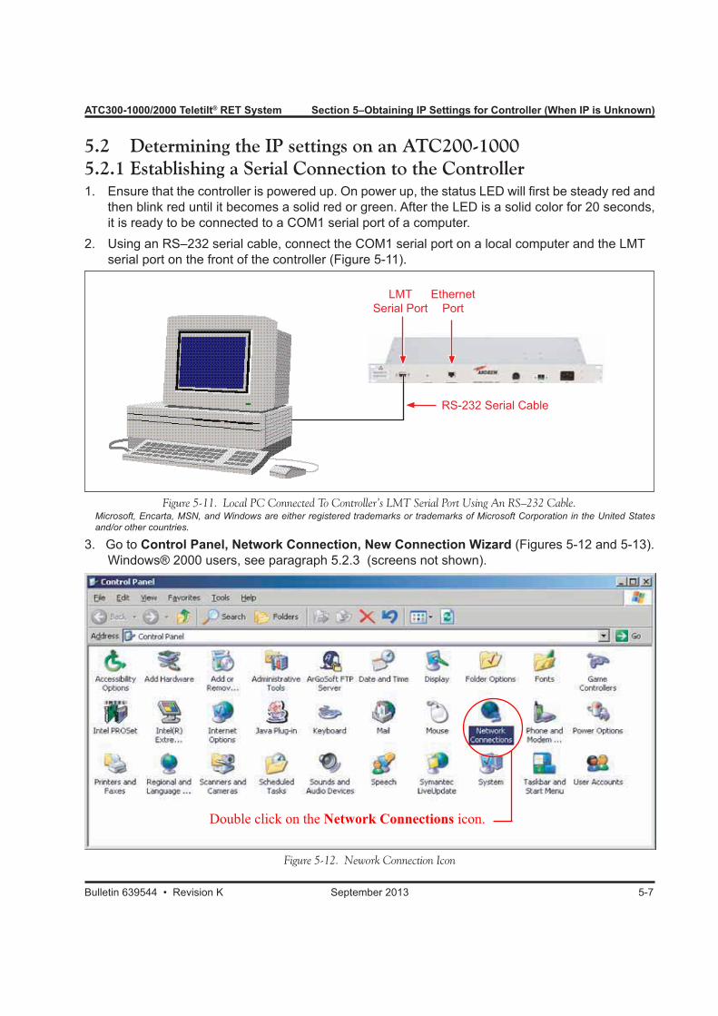
5.2 Determining the IP settings on an ATC200-10005.2.1 Establishing a Serial Connection to the Controller1. Ensure that the controller is powered up. On power up, the status LED will first be steady red and
then blink red until it becomes a solid red or green. After the LED is a solid color for 20 seconds, it is ready to be connected to a COM1 serial port of a computer.
2. Using an RS–232 serial cable, connect the COM1 serial port on a local computer and the LMT serial port on the front of the controller (Figure 5-11).
Microsoft, Encarta, MSN, and Windows are either registered trademarks or trademarks of Microsoft Corporation in the United States and/or other countries.
3. Go to Control Panel, Network Connection, New Connection Wizard (Figures 5-12 and 5-13).Windows® 2000 users, see paragraph 5.2.3 (screens not shown).
Double click on the Network Connections icon.
Figure 5-11. Local PC Connected To Controller’s LMT Serial Port Using An RS–232 Cable.
Figure 5-12. Nework Connection Icon
RS-232 Serial Cable
LMT Serial Port
Ethernet Port
Section 5–Obtaining IP Settings for Controller (When IP is Unknown) ATC300-1000/2000 Teletilt® RET System
5-8 September 2013 Bulletin 639544 • Revision K
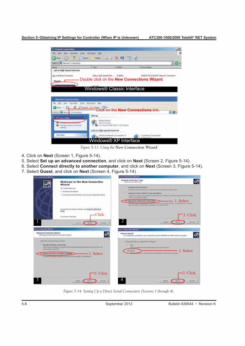
Figure 5-13. Using the New Connection Wizard
Windows® Classic Interface
Windows® XP Interface
Click on the New Connections link.
Double click on the New Connections Wizard.
4. Click on Next (Screen 1, Figure 5-14).5. Select Set up an advanced connection, and click on Next (Screen 2, Figure 5-14).6. Select Connect directly to another computer, and click on Next (Screen 3, Figure 5-14).7. Select Guest, and click on Next (Screen 4, Figure 5-14) .
Figure 5-14. Setting Up a Direct Serial Connection (Screens 1 through 4).
Click.
12. Click.
1. Select.
2
2. Click.
1. Select.
42. Click.
1. Select.
3
ATC300-1000/2000 Teletilt® RET System Section 5–Obtaining IP Settings for Controller (When IP is Unknown)
Bulletin 639544 • Revision K September 2013 5-9
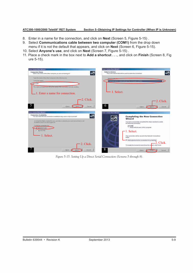
8. Enter in a name for the connection, and click on Next (Screen 5, Figure 5-15) .9. Select Communications cable between two computer (COM1) from the drop down menu if it is not the default that appears, and click on Next (Screen 6, Figure 5-15).10. Select Anyone’s use, and click on Next (Screen 7, Figure 5-15) .11. Place a check mark in the box next to Add a shortcut . . ., and click on Finish (Screen 8, Fig ure 5-15).
2. Click.
2. Click.2. Click.
2. Click.
Figure 5-15. Setting Up a Direct Serial Connection (Screens 5 through 8).
1. Enter a name for connection. 1. Select.
1. Select.1. Select.
5 6
87
Section 5–Obtaining IP Settings for Controller (When IP is Unknown) ATC300-1000/2000 Teletilt® RET System
5-10 September 2013 Bulletin 639544 • Revision K
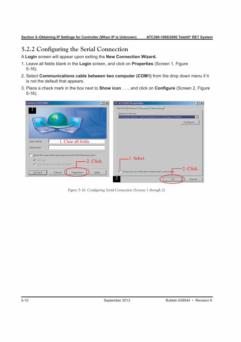
5.2.2 Configuring the Serial ConnectionA Login screen will appear upon exiting the New Connection Wizard. 1. Leave all fields blank in the Login screen, and click on Properties (Screen 1, Figure 5-16).2. Select Communications cable between two computer (COM1) from the drop down menu if it is not the default that appears.3. Place a check mark in the box next to Show icon . . ., and click on Configure (Screen 2, Figure 5-16).
Figure 5-16. Configuring Serial Connection (Screens 1 through 2).
2. Click.
1. Clear all fields.
1
2. Click.
1. Select.
2
ATC300-1000/2000 Teletilt® RET System Section 5–Obtaining IP Settings for Controller (When IP is Unknown)
Bulletin 639544 • Revision K September 2013 5-11
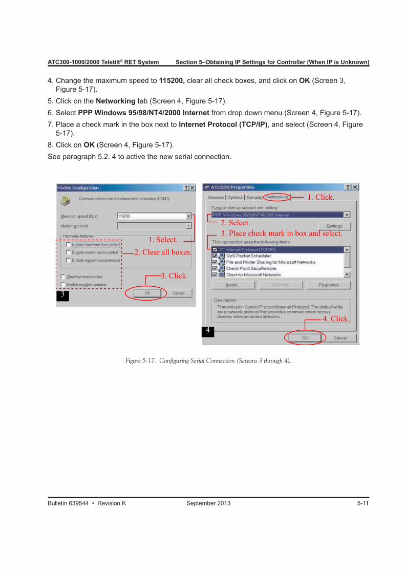
4. Change the maximum speed to 115200, clear all check boxes, and click on OK (Screen 3, Figure 5-17).5. Click on the Networking tab (Screen 4, Figure 5-17).6. Select PPP Windows 95/98/NT4/2000 Internet from drop down menu (Screen 4, Figure 5-17).7. Place a check mark in the box next to Internet Protocol (TCP/IP), and select (Screen 4, Figure 5-17).8. Click on OK (Screen 4, Figure 5-17).See paragraph 5.2. 4 to active the new serial connection.
44. Click.
1. Click.
2. Select.3. Place check mark in box and select.
3
3. Click.
1. Select.2. Clear all boxes.
Figure 5-17. Configuring Serial Connection (Screens 3 through 4).

Section 5–Obtaining IP Settings for Controller (When IP is Unknown) ATC300-1000/2000 Teletilt® RET System
5-12 September 2013 Bulletin 639544 • Revision K
5.2.3 Establishing a Serial Connection for Windows® 2000 Users
1. Go to Control Panel→Network and Dial-up Connections→Make a New Connection→Network Connection Wizard (screens not shown).2. Select Connect directly to another computer, and click on Next.3. Select Guest, and click on Next (Screen 4, Figure 5-14).4. Select either COM1 or COM2 from the drop down menu.5. Select For all users, and click on Next.6. Enter in a name for the connection, and click on Next.7. Clear all the fields, and click on Properties.8. Select either COM1 or COM2 from the drop down menu (use the same selection as chosen in step 5).9. Select the Show icon in taskbar when connected option, and click on Configure.10. Change the maximum speed to 115200, clear all check boxes, and click on OK.11. Click on the Options tab.12. Select the Display progress while connecting and Prompt for name password, certificate, etc options.13. Click on the Networking tab.14. Select PPP Windows 95/98/NT4/2000 Internet from drop down menu.15. Place a check mark in the box next to Internet Protocol.16. Click on OK.See paragraph 5.2.4 to activate the new serial connection.
ATC300-1000/2000 Teletilt® RET System Section 5–Obtaining IP Settings for Controller (When IP is Unknown)
Bulletin 639544 • Revision K September 2013 5-13
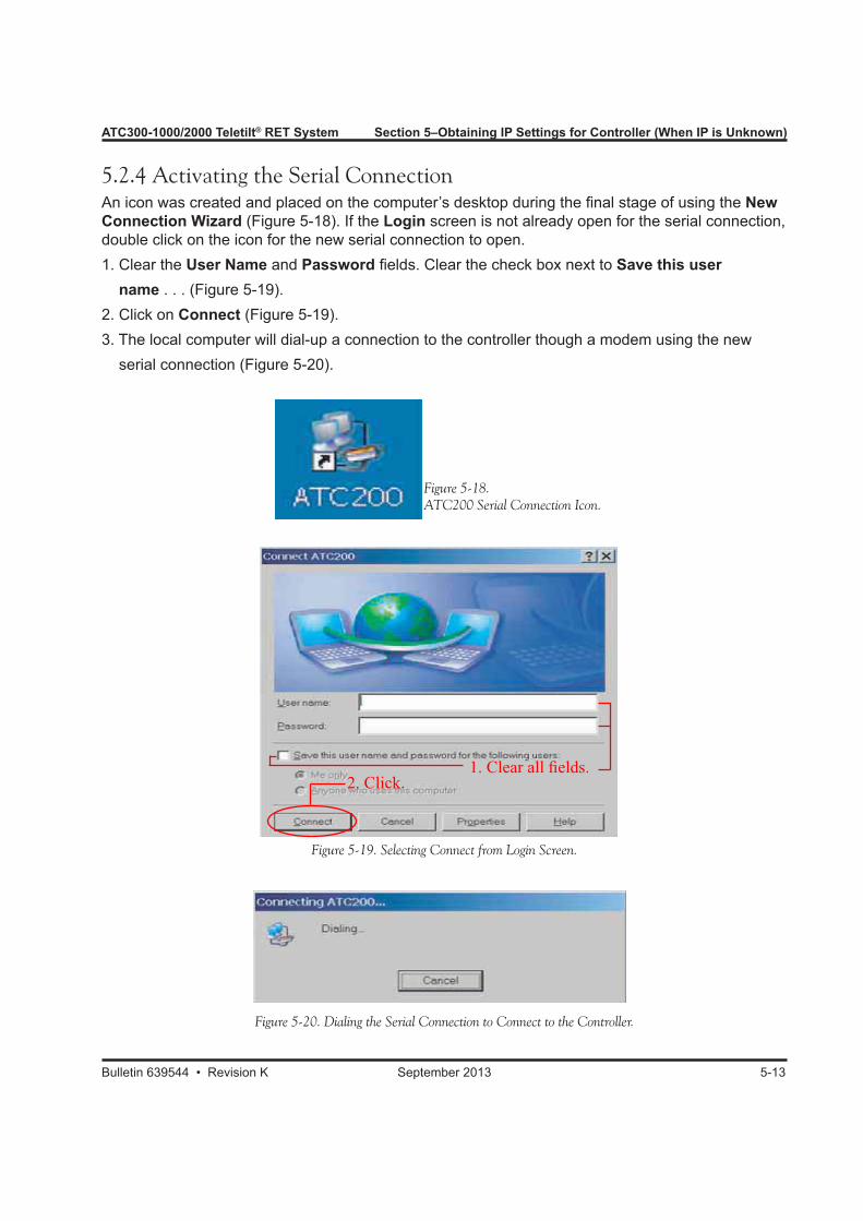
5.2.4 Activating the Serial ConnectionAn icon was created and placed on the computer’s desktop during the final stage of using the NewConnection Wizard (Figure 5-18). If the Login screen is not already open for the serial connection,double click on the icon for the new serial connection to open.1. Clear the User Name and Password fields. Clear the check box next to Save this user name . . . (Figure 5-19).2. Click on Connect (Figure 5-19).3. The local computer will dial-up a connection to the controller though a modem using the new serial connection (Figure 5-20).
Figure 5-20. Dialing the Serial Connection to Connect to the Controller.
Figure 5-19. Selecting Connect from Login Screen.
Figure 5-18.ATC200 Serial Connection Icon.
1. Clear all fields.2. Click.
Section 5–Obtaining IP Settings for Controller (When IP is Unknown) ATC300-1000/2000 Teletilt® RET System
5-14 September 2013 Bulletin 639544 • Revision K
5.2.5 Accessing the Controller Interface Over the Serial Connection toObtain the Controller’s IP Settings1. Ensure that the controller is powered up.2. Ensure the serial connection is active (dialed up successfully) from the local computer to the controller (see paragraph 5.2.4). Note that if serial connection is not operating, the Windows® default setting for the 16550 interrupt threshold may be too high. This causes missed characters if the computer is busy. This setting can be adjusted to a lower rate to correct this condition. Contact the company network administrator for assistance, if needed.3. Open an Internet browser (Netscape and Mozilla browsers not supported).4. Type in the controller’s serial IP address (10.254.254.253) into the URL address window (Figure 5-21). This serial IP address is the default for all ATC200-1000 controllers. Note that the computer will not be able to access the Internet during the time it is connected to the controller over the serial connection. If the web browser is stalled from trying to access the Internet, click on the Stop button to discontinue this attempt.
IMPORTANT! In the event the controller needs to be rebooted/restarted during the time it is connected to the computer over a serial connection, IMMEDIATELY disconnect the serial cable from the controller after rebooting. Wait until the lights stop flashing on the controller before restoring the serial connection to the computer.
1. Enter controller’s serial IP address.
2. Click.Figure 5-21. Entering the Controller’s Serial IP Address.
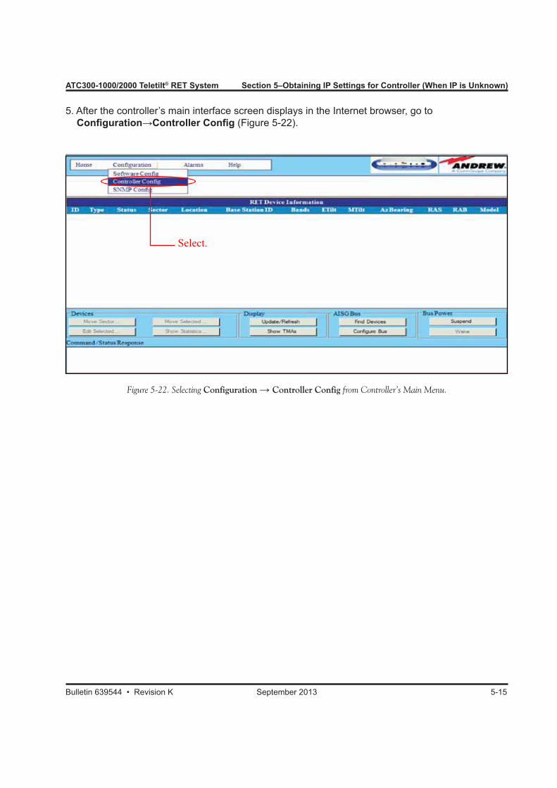
ATC300-1000/2000 Teletilt® RET System Section 5–Obtaining IP Settings for Controller (When IP is Unknown)
Bulletin 639544 • Revision K September 2013 5-15
5. After the controller’s main interface screen displays in the Internet browser, go to Configuration→Controller Config (Figure 5-22).
Figure 5-22. Selecting Configuration → Controller Config from Controller’s Main Menu.
Select.
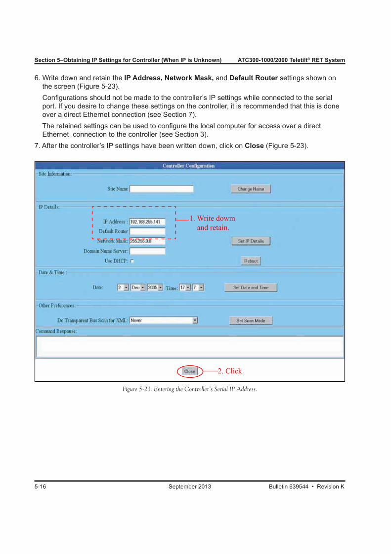
Section 5–Obtaining IP Settings for Controller (When IP is Unknown) ATC300-1000/2000 Teletilt® RET System
5-16 September 2013 Bulletin 639544 • Revision K
6. Write down and retain the IP Address, Network Mask, and Default Router settings shown on the screen (Figure 5-23). Configurations should not be made to the controller’s IP settings while connected to the serial port. If you desire to change these settings on the controller, it is recommended that this is done over a direct Ethernet connection (see Section 7). The retained settings can be used to configure the local computer for access over a direct Ethernet connection to the controller (see Section 3).7. After the controller’s IP settings have been written down, click on Close (Figure 5-23).
Figure 5-23. Entering the Controller’s Serial IP Address.
2. Click.
1. Write dowm and retain.
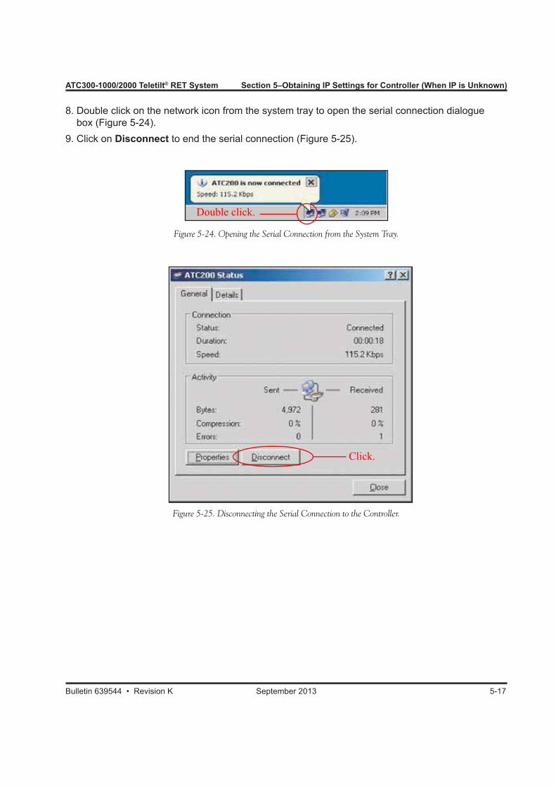
ATC300-1000/2000 Teletilt® RET System Section 5–Obtaining IP Settings for Controller (When IP is Unknown)
Bulletin 639544 • Revision K September 2013 5-17
8. Double click on the network icon from the system tray to open the serial connection dialogue box (Figure 5-24).9. Click on Disconnect to end the serial connection (Figure 5-25).
Figure 5-24. Opening the Serial Connection from the System Tray.
Figure 5-25. Disconnecting the Serial Connection to the Controller.
Double click.
Click.

Section 5–Obtaining IP Settings for Controller (When IP is Unknown) ATC300-1000/2000 Teletilt® RET System
5-18 September 2013 Bulletin 639544 • Revision K
This page intentionally left blank.

Bulletin 639544 • Revision K September 2013
Part 2Accessing the Controller

Part 2–Accessing the Controller ATC300-1000/2000 Teletilt® RET System
September 2013 Bulletin 639544 • Revision K
This page intentionally left blank.
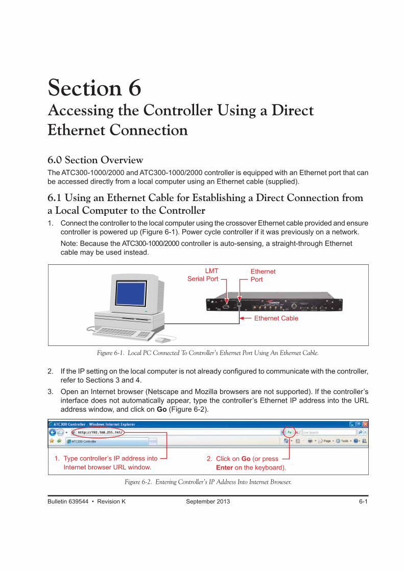
Bulletin 639544 • Revision K September 2013 6-1
Section 6Accessing the Controller Using a Direct Ethernet Connection
6.0 Section OverviewThe ATC300-1000/2000 and ATC300-1000/2000 controller is equipped with an Ethernet port that can be accessed directly from a local computer using an Ethernet cable (supplied).
6.1 Using an Ethernet Cable for Establishing a Direct Connection from a Local Computer to the Controller1. Connect the controller to the local computer using the crossover Ethernet cable provided and ensure
controller is powered up (Figure 6-1). Power cycle controller if it was previously on a network. Note: Because the ATC300-1000/2000 controller is auto-sensing, a straight-through Ethernet
cable may be used instead.
Figure 6-1. Local PC Connected To Controller’s Ethernet Port Using An Ethernet Cable.
Figure 6-2. Entering Controller’s IP Address Into Internet Browser.
1. Type controller’s IP address into Internet browser URL window.
2. Click on Go (or press Enter on the keyboard).
LMT Serial Port
Ethernet Port
Ethernet Cable
2. If the IP setting on the local computer is not already configured to communicate with the controller, refer to Sections 3 and 4.
3. Open an Internet browser (Netscape and Mozilla browsers are not supported). If the controller’s interface does not automatically appear, type the controller’s Ethernet IP address into the URL address window, and click on Go (Figure 6-2).
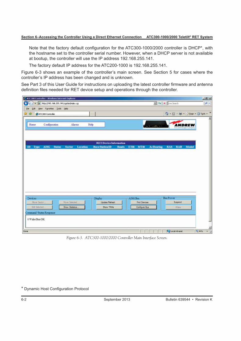
Section 6–Accessing the Controller Using a Direct Ethernet Connection ATC300-1000/2000 Teletilt® RET System
6-2 September 2013 Bulletin 639544 • Revision K
Figure 6-3. ATC300-1000/2000 Controller Main Interface Screen.
Note that the factory default configuration for the ATC300-1000/2000 controller is DHCP*, with the hostname set to the controller serial number. However, when a DHCP server is not available at bootup, the controller will use the IP address 192.168.255.141.
The factory default IP address for the ATC200-1000 is 192.168.255.141.Figure 6-3 shows an example of the controller’s main screen. See Section 5 for cases where the controller’s IP address has been changed and is unknown.See Part 3 of this User Guide for instructions on uploading the latest controller firmware and antenna definition files needed for RET device setup and operations through the controller.
* Dynamic Host Configuration Protocol
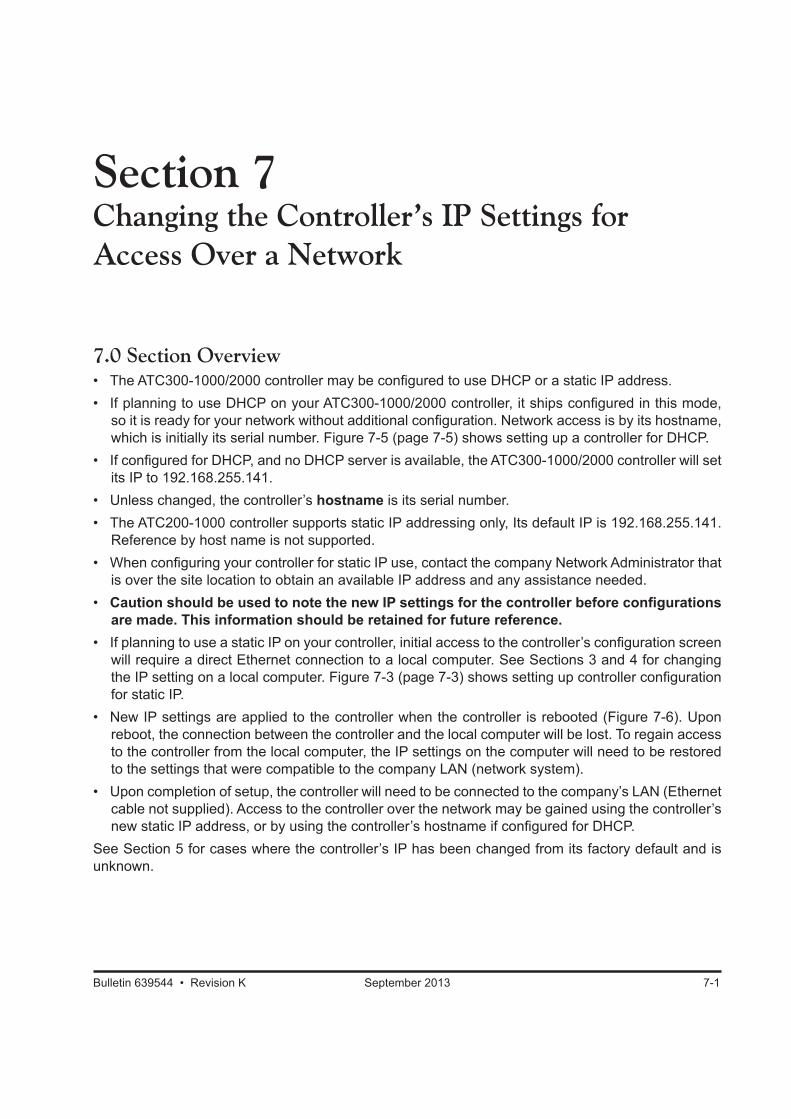
Bulletin 639544 • Revision K September 2013 7-1
Section 7Changing the Controller’s IP Settings for Access Over a Network
7.0 Section Overview• The ATC300-1000/2000 controller may be configured to use DHCP or a static IP address.• If planning to use DHCP on your ATC300-1000/2000 controller, it ships configured in this mode,
so it is ready for your network without additional configuration. Network access is by its hostname, which is initially its serial number. Figure 7-5 (page 7-5) shows setting up a controller for DHCP.
• If configured for DHCP, and no DHCP server is available, the ATC300-1000/2000 controller will set its IP to 192.168.255.141.
• Unless changed, the controller’s hostname is its serial number.• The ATC200-1000 controller supports static IP addressing only, Its default IP is 192.168.255.141.
Reference by host name is not supported.• When configuring your controller for static IP use, contact the company Network Administrator that
is over the site location to obtain an available IP address and any assistance needed.• Caution should be used to note the new IP settings for the controller before configurations
are made. This information should be retained for future reference.• If planning to use a static IP on your controller, initial access to the controller’s configuration screen
will require a direct Ethernet connection to a local computer. See Sections 3 and 4 for changing the IP setting on a local computer. Figure 7-3 (page 7-3) shows setting up controller configuration for static IP.
• New IP settings are applied to the controller when the controller is rebooted (Figure 7-6). Upon reboot, the connection between the controller and the local computer will be lost. To regain access to the controller from the local computer, the IP settings on the computer will need to be restored to the settings that were compatible to the company LAN (network system).
• Upon completion of setup, the controller will need to be connected to the company’s LAN (Ethernet cable not supplied). Access to the controller over the network may be gained using the controller’s new static IP address, or by using the controller’s hostname if configured for DHCP.
See Section 5 for cases where the controller’s IP has been changed from its factory default and is unknown.
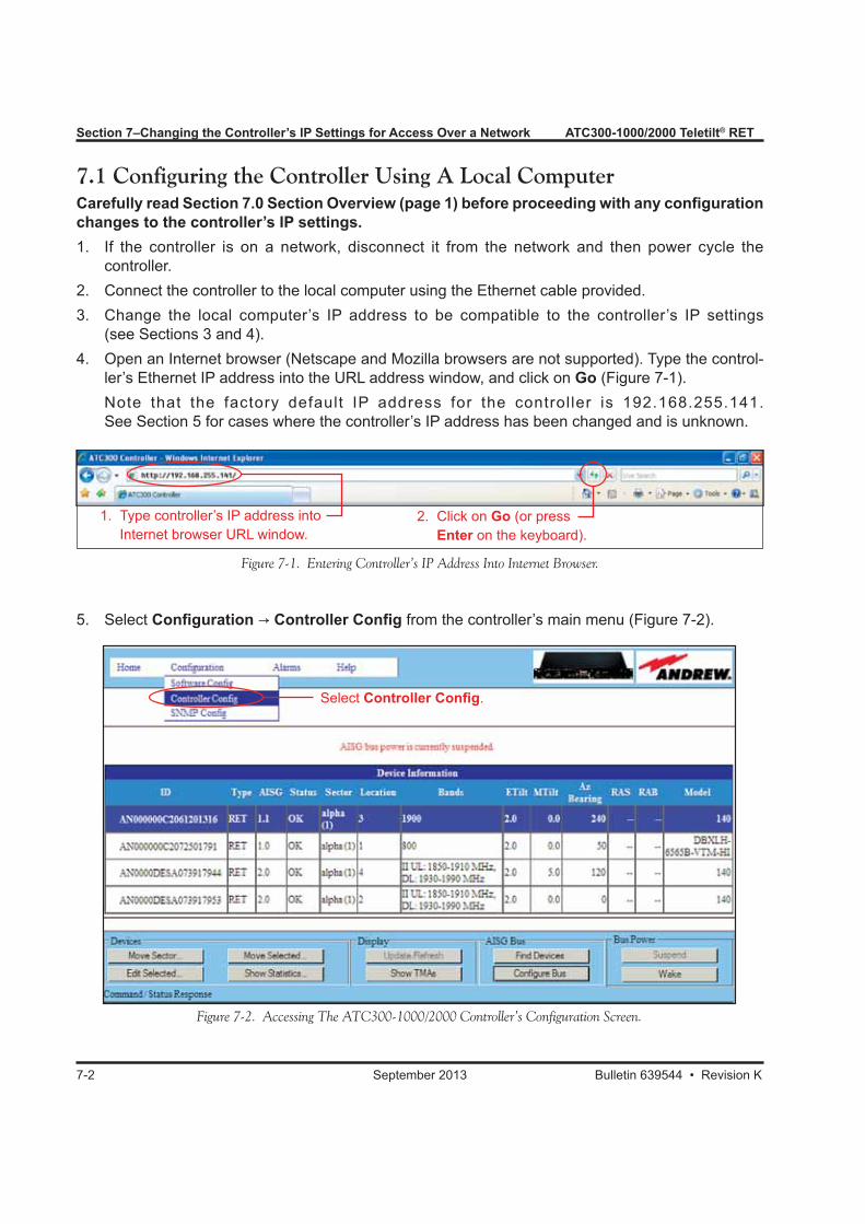
7-2 September 2013 Bulletin 639544 • Revision K
Section 7–Changing the Controller’s IP Settings for Access Over a Network ATC300-1000/2000 Teletilt® RET
7.1 Configuring the Controller Using A Local ComputerCarefully read Section 7.0 Section Overview (page 1) before proceeding with any configuration changes to the controller’s IP settings.1. If the controller is on a network, disconnect it from the network and then power cycle the
controller.2. Connect the controller to the local computer using the Ethernet cable provided.3. Change the local computer’s IP address to be compatible to the controller’s IP settings
(see Sections 3 and 4).4. Open an Internet browser (Netscape and Mozilla browsers are not supported). Type the control-
ler’s Ethernet IP address into the URL address window, and click on Go (Figure 7-1). Note that the factory default IP address for the control ler is 192.168.255.141.
See Section 5 for cases where the controller’s IP address has been changed and is unknown.
Figure 7-1. Entering Controller’s IP Address Into Internet Browser.
1. Type controller’s IP address into Internet browser URL window.
2. Click on Go (or press Enter on the keyboard).
Figure 7-2. Accessing The ATC300-1000/2000 Controller’s Configuration Screen.
Select Controller Config.
5. Select Configuration → Controller Config from the controller’s main menu (Figure 7-2).
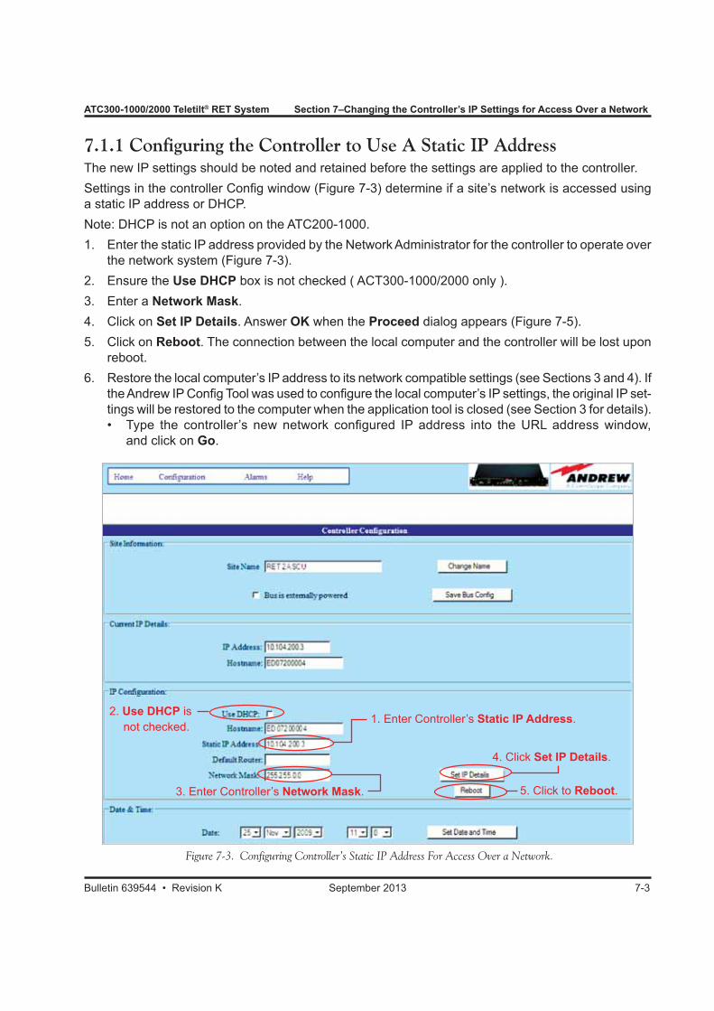
ATC300-1000/2000 Teletilt® RET System Section 7–Changing the Controller’s IP Settings for Access Over a Network
Bulletin 639544 • Revision K September 2013 7-3
7.1.1 Configuring the Controller to Use A Static IP AddressThe new IP settings should be noted and retained before the settings are applied to the controller.Settings in the controller Config window (Figure 7-3) determine if a site’s network is accessed using a static IP address or DHCP.Note: DHCP is not an option on the ATC200-1000. 1. Enter the static IP address provided by the Network Administrator for the controller to operate over
the network system (Figure 7-3).2. Ensure the Use DHCP box is not checked ( ACT300-1000/2000 only ).3. Enter a Network Mask.4. Click on Set IP Details. Answer OK when the Proceed dialog appears (Figure 7-5).5. Click on Reboot. The connection between the local computer and the controller will be lost upon
reboot.6. Restore the local computer’s IP address to its network compatible settings (see Sections 3 and 4). If
the Andrew IP Config Tool was used to configure the local computer’s IP settings, the original IP set-tings will be restored to the computer when the application tool is closed (see Section 3 for details). • Type the controller’s new network configured IP address into the URL address window, and click on Go.
Figure 7-3. Configuring Controller’s Static IP Address For Access Over a Network.
2. Use DHCP is not checked.
3. Enter Controller’s Network Mask.
1. Enter Controller’s Static IP Address.
4. Click Set IP Details.
5. Click to Reboot.
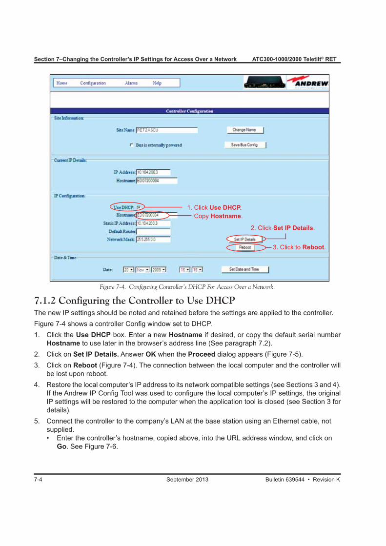
7-4 September 2013 Bulletin 639544 • Revision K
Section 7–Changing the Controller’s IP Settings for Access Over a Network ATC300-1000/2000 Teletilt® RET
7.1.2 Configuring the Controller to Use DHCPThe new IP settings should be noted and retained before the settings are applied to the controller.Figure 7-4 shows a controller Config window set to DHCP.1. Click the Use DHCP box. Enter a new Hostname if desired, or copy the default serial number
Hostname to use later in the browser’s address line (See paragraph 7.2).2. Click on Set IP Details. Answer OK when the Proceed dialog appears (Figure 7-5).3. Click on Reboot (Figure 7-4). The connection between the local computer and the controller will
be lost upon reboot.4. Restore the local computer’s IP address to its network compatible settings (see Sections 3 and 4).
If the Andrew IP Config Tool was used to configure the local computer’s IP settings, the original IP settings will be restored to the computer when the application tool is closed (see Section 3 for details).
5. Connect the controller to the company’s LAN at the base station using an Ethernet cable, not supplied. • Enter the controller’s hostname, copied above, into the URL address window, and click on Go. See Figure 7-6.
1. Click Use DHCP. Copy Hostname.
2. Click Set IP Details.
3. Click to Reboot.
Figure 7-4. Configuring Controller’s DHCP For Access Over a Network.
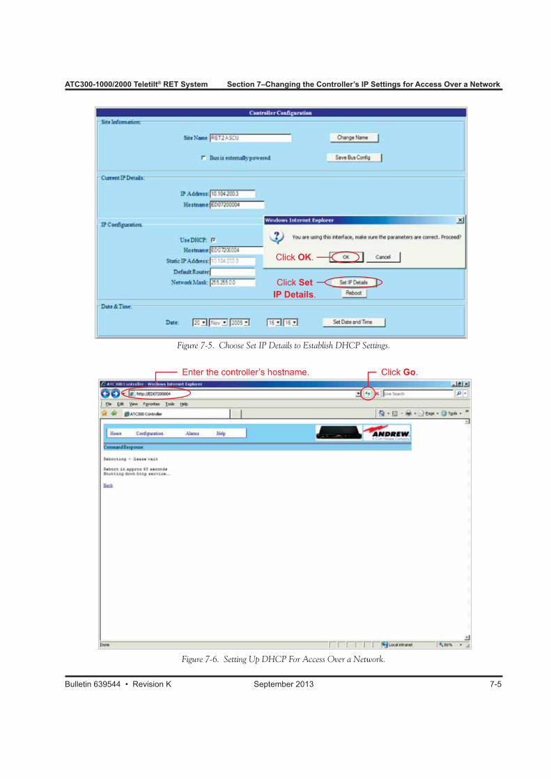
ATC300-1000/2000 Teletilt® RET System Section 7–Changing the Controller’s IP Settings for Access Over a Network
Bulletin 639544 • Revision K September 2013 7-5
Figure 7-5. Choose Set IP Details to Establish DHCP Settings.
Figure 7-6. Setting Up DHCP For Access Over a Network.
Enter the controller’s hostname. Click Go.
Click OK.
Click Set IP Details.
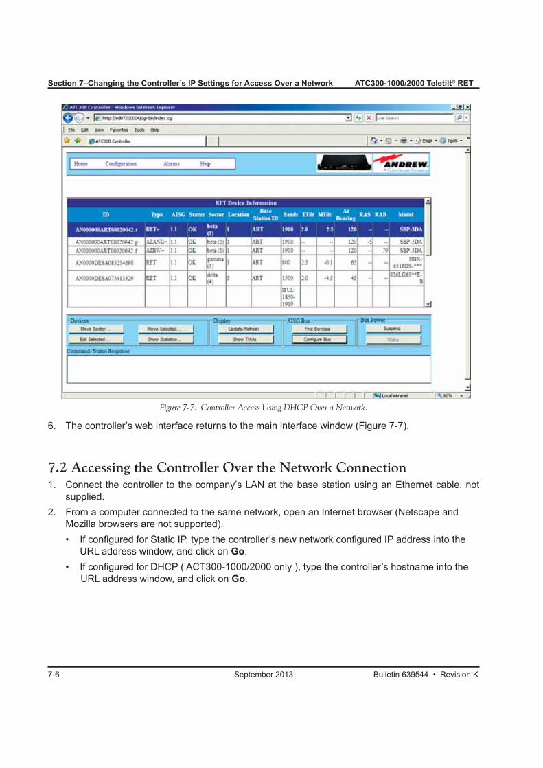
7-6 September 2013 Bulletin 639544 • Revision K
Section 7–Changing the Controller’s IP Settings for Access Over a Network ATC300-1000/2000 Teletilt® RET
7.2 Accessing the Controller Over the Network Connection1. Connect the controller to the company’s LAN at the base station using an Ethernet cable, not
supplied.2. From a computer connected to the same network, open an Internet browser (Netscape and
Mozilla browsers are not supported). • If configured for Static IP, type the controller’s new network configured IP address into the
URL address window, and click on Go. • If configured for DHCP ( ACT300-1000/2000 only ), type the controller’s hostname into the URL address window, and click on Go.
Figure 7-7. Controller Access Using DHCP Over a Network.
6. The controller’s web interface returns to the main interface window (Figure 7-7).

Bulletin 639544 • Revision K September 2013 8-1
Section 8Controller Configuration Options
8.0 Section Overview• The ATC300/200 controller is equipped with an SNMP (Simple Network Management Protocol)
agent that allows remote access using an SNMP manager.• Andrew provides the MIB (Management Information Base), which is supported by the ATC300/200
controller SNMP agent, upon request.• SNMP is a well-defined protocol used in the industry to manage devices remotely.• The ATC300/200 controller allows configuration of the unit site name.• The ATC300 allows password protection on the web page interface.• The ATC300 provides some special case controller configuration options.
8.1 Configuring the Controller for an SNMP ManagerThe controller’s SNMP agent can be accessed through the menu option Configuration → SNMP Config (Figure 8-1).
Figure 8-1. Selecting Menu Option To Access SNMP Configuration Page.
Accessing the SNMP Agent.
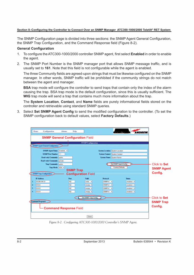
Section 8–Configuring the Controller to Connect Over an SNMP Manager ATC300-1000/2000 Teletilt® RET System
8-2 September 2013 Bulletin 639544 • Revision K
Figure 8-2. Configuring ATC300-1000/2000 Controller’s SNMP Agent.
The SNMP Configuration page is divided into three sections: the SNMP Agent General Configuration, the SNMP Trap Configuration, and the Command Response field (Figure 8-2).General Configuration1. To configure the ATC300-1000/2000 controller SNMP agent, first select Enabled in order to enable
the agent. 2. The SNMP Port Number is the SNMP manager port that allows SNMP message traffic, and is
usually set to 161. Note that this field is not configurable while the agent is enabled. The three Community fields are agreed-upon strings that must be likewise configured on the SNMP
manager. In other words, SNMP traffic will be prohibited if the community strings do not match between the agent and manager.
BSA trap mode will configure the controller to send traps that contain only the index of the alarm causing the trap. BSA trap mode is the default configuration, since this is usually sufficient. The WIG trap mode will send a trap that contains much more information about the trap.
The System Location, Contact, and Name fields are purely informational fields stored on the controller and retrievable using standard SNMP queries.
3. Select Set SNMP Agent Config to send the modified configuration to the controller. (To set the SNMP configuration back to default values, select Factory Defaults.)
Click to Set SNMP Agent Config.
Click to Set SNMP Trap Config.Command Response Field
SNMP Trap Configuration Field
SNMP General Configuration Field
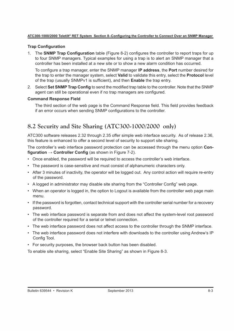
ATC300-1000/2000 Teletilt® RET System Section 8–Configuring the Controller to Connect Over an SNMP Manager
Bulletin 639544 • Revision K September 2013 8-3
Trap Configuration1. The SNMP Trap Configuration table (Figure 8-2) configures the controller to report traps for up
to four SNMP managers. Typical examples for using a trap is to alert an SNMP manager that a controller has been installed at a new site or to show a new alarm condition has occurred.
To configure a trap manager, enter the SNMP manager IP address, the Port number desired for the trap to enter the manager system, select Valid to validate this entry, select the Protocol level of the trap (usually SNMPv1 is sufficient), and then Enable the trap entry.
2. Select Set SNMP Trap Config to send the modified trap table to the controller. Note that the SNMP agent can still be operational even if no trap managers are configured.
Command Response Field The third section of the web page is the Command Response field. This field provides feedback
if an error occurs when sending SNMP configurations to the controller.
8.2 Security and Site Sharing (ATC300-1000/2000 only)ATC300 software releases 2.32 through 2.35 offer simple web interface security. As of release 2.36, this feature is enhanced to offer a second level of security to support site sharing.The controller’s web interface password protection can be accessed through the menu option Con-figuration → Controller Config (as shown in Figure 7-2). • Once enabled, the password will be required to access the controller’s web interface.• The password is case-sensitive and must consist of alphanumeric characters only.• After 3 minutes of inactivity, the operator will be logged out. Any control action will require re-entry
of the password.• A logged in administrator may disable site sharing from the “Controller Config” web page.• When an operator is logged in, the option to Logout is available from the controller web page main
menu.• If the password is forgotten, contact technical support with the controller serial number for a recovery
password.• The web interface password is separate from and does not affect the system-level root password
of the controller required for a serial or telnet connection.• The web interface password does not affect access to the controller through the SNMP interface.• The web interface password does not interfere with downloads to the controller using Andrew’s IP
Config Tool.• For security purposes, the browser back button has been disabled.To enable site sharing, select “Enable Site Sharing” as shown in Figure 8-3.
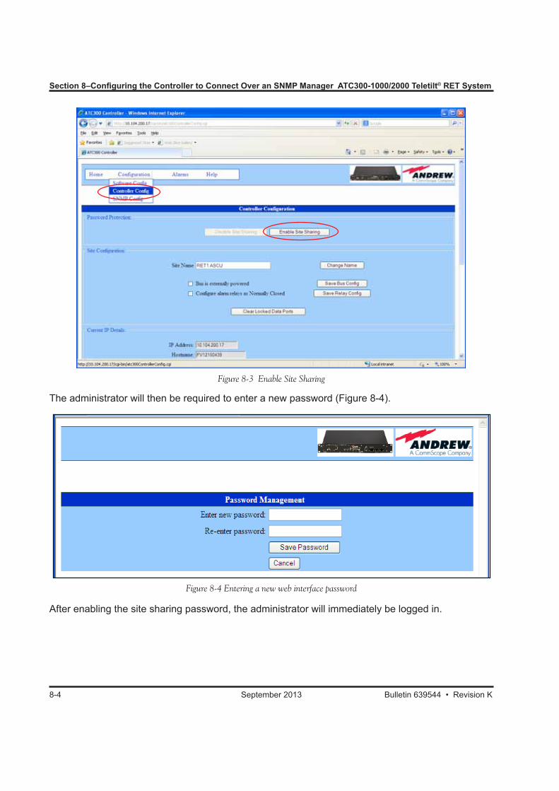
Section 8–Configuring the Controller to Connect Over an SNMP Manager ATC300-1000/2000 Teletilt® RET System
8-4 September 2013 Bulletin 639544 • Revision K
Figure 8-3 Enable Site Sharing
Figure 8-4 Entering a new web interface password
The administrator will then be required to enter a new password (Figure 8-4).
After enabling the site sharing password, the administrator will immediately be logged in.
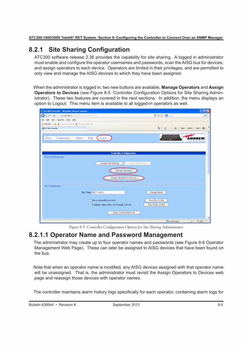
ATC300-1000/2000 Teletilt® RET System Section 8–Configuring the Controller to Connect Over an SNMP Manager
Bulletin 639544 • Revision K September 2013 8-5
8.2.1 Site Sharing Configuration ATC300 software release 2.36 provides the capability for site sharing. A logged in administrator
must enable and configure the operator usernames and passwords, scan the AISG bus for devices, and assign operators to each device. Operators are limited in their privileges, and are permitted to only view and manage the AISG devices to which they have been assigned.
When the administrator is logged in, two new buttons are available, Manage Operators and Assign Operators to Devices (see Figure 8-5 Controller Configuration Options for Site Sharing Admin-istrator). These two features are covered in the next sections. In addition, the menu displays an option to Logout. This menu item is available to all logged-in operators as well.
Figure 8-5 Controller Configuration Options for Site Sharing Administrator
8.2.1.1 Operator Name and Password Management The administrator may create up to four operator names and passwords (see Figure 8-6 Operator
Management Web Page). These can later be assigned to AISG devices that have been found on the bus.
Note that when an operator name is modified, any AISG devices assigned with that operator name will be unassigned. That is, the administrator must revisit the Assign Operators to Devices web page and reassign those devices with operator names.
The controller maintains alarm history logs specifically for each operator, containing alarm logs for
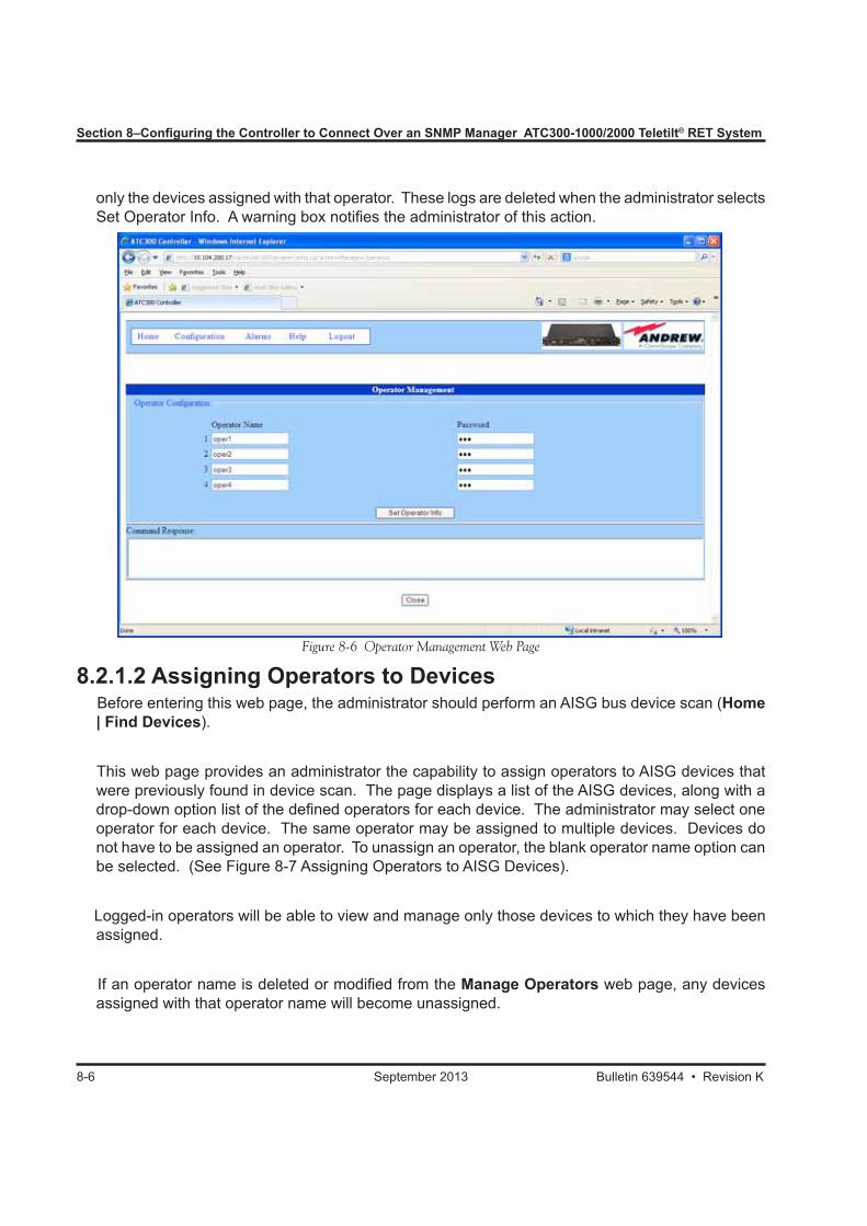
Section 8–Configuring the Controller to Connect Over an SNMP Manager ATC300-1000/2000 Teletilt® RET System
8-6 September 2013 Bulletin 639544 • Revision K
only the devices assigned with that operator. These logs are deleted when the administrator selects Set Operator Info. A warning box notifies the administrator of this action.
Figure 8-6 Operator Management Web Page
8.2.1.2 Assigning Operators to Devices Before entering this web page, the administrator should perform an AISG bus device scan (Home
| Find Devices).
This web page provides an administrator the capability to assign operators to AISG devices that were previously found in device scan. The page displays a list of the AISG devices, along with a drop-down option list of the defined operators for each device. The administrator may select one operator for each device. The same operator may be assigned to multiple devices. Devices do not have to be assigned an operator. To unassign an operator, the blank operator name option can be selected. (See Figure 8-7 Assigning Operators to AISG Devices).
Logged-in operators will be able to view and manage only those devices to which they have been assigned.
If an operator name is deleted or modified from the Manage Operators web page, any devices assigned with that operator name will become unassigned.
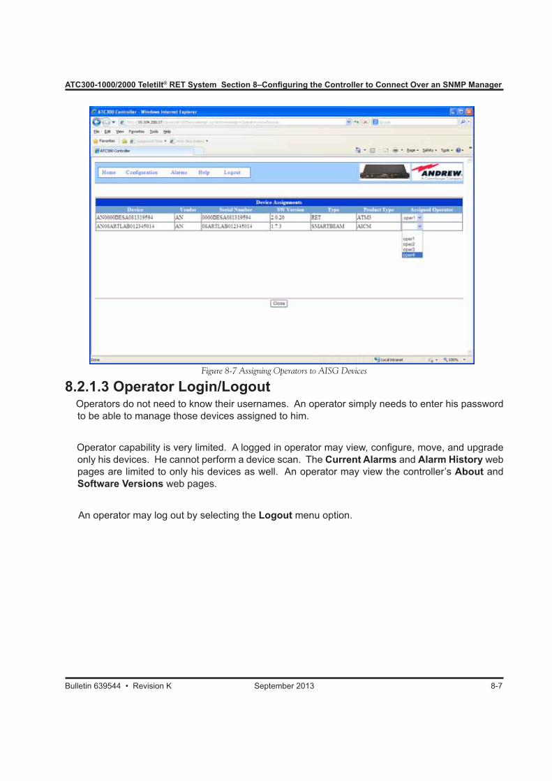
ATC300-1000/2000 Teletilt® RET System Section 8–Configuring the Controller to Connect Over an SNMP Manager
Bulletin 639544 • Revision K September 2013 8-7
8.2.1.3 Operator Login/Logout Operators do not need to know their usernames. An operator simply needs to enter his password
to be able to manage those devices assigned to him.
Operator capability is very limited. A logged in operator may view, configure, move, and upgrade only his devices. He cannot perform a device scan. The Current Alarms and Alarm History web pages are limited to only his devices as well. An operator may view the controller’s About and Software Versions web pages.
An operator may log out by selecting the Logout menu option.
Figure 8-7 Assigning Operators to AISG Devices
Section 8–Configuring the Controller to Connect Over an SNMP Manager ATC300-1000/2000 Teletilt® RET System
8-8 September 2013 Bulletin 639544 • Revision K
8.3 Site ConfigurationThe controller allows configuration of other options that can be accessed through the menu option Configuration → Controller Config (as shown in Figure 7-2).
8.3.1 Site NameThe controller site name defaults to “RET1 ASCU” but can be modified at any time. This identifier is not usually important unless the controller is one of many nodes managed by network management software such as Andrew’s Site Manager.
8.3.2 External Bus Power (ATC300-1000/2000 only)By default, the ATC300-1000/2000 limits the number of ALD devices in its database to 32 due to power requirements. However, if the devices are externally powered, this option may be selected to expand that limit to 64 ALD devices.
8.3.3 Alarm Relay Configuration (ATC300-1000/2000 only)The alarm relays on the ATC300-1000/2000 are “normally open” by default. This option changes that logic and treats the relays as “normally closed”.Note that after changing this configuration, the controller may need to be rebooted for the relays to reflect the current alarm states correctly.

ATC300-1000/2000 Teletilt® RET System Section 8–Configuring the Controller to Connect Over an SNMP Manager
Bulletin 639544 • Revision K September 2013 8-9
This page intentionally left blank.
Bulletin 639544 • Revision K September 2013
Part 3Uploading Firmware

Part 3–Uploading Firmware ATC300-1000/2000 Teletilt® RET System
September 2013 Bulletin 639544 • Revision K
This page intentionally left blank.

Bulletin 639544 • Revision K September 2013 9-1
Section 9Uploading Controller Firmware and Antenna Definition Files Using the IP Config Tool9.0 Section Overview• The Andrew IP Config Tool can be used for uploading firmware to the controller over its FTP server.
For uploading firmware to the controller over a direct connection, see paragraphs 9.2 through 9.5. For uploading firmware to the controller over a LAN, see paragraphs 9.3 through 9.5. For ATC200 and ATC300 2.32 and earlier, firmware can also be uploaded to the controller using a third party FTP server (see Appendix C).
• For ATC300 2.34 and later, firmware can be installed using the web interface without IP Config Tool or a third-party FTP server.
• The IP Config Tool is compatible for use on computers operating in the English language using Windows® 2000, Windows® XP or Windows 7. This tool includes an FTP server for file upload. If another FTP server is active on the local computer, a conflict may occur (see paragraph 9.6). See Appendix A to disable Windows® XP SP2 Firewall. The IP Config Tool does not work with Windows Vista (see Appendix B).
• Periodically, updates are made to the antenna definition file to add data for new antenna models and to maintain the latest data available for existing antennas compatible for the controller system. These updates are made automatically when the operator installs new controller firmware, because antenna definition file releases are bundled with controller firmware.
9.1 Required ResourcesHardware• ATC300-1000/2000 or ATC200-1000 controller w/power cord• To connect to PC or laptop, use the Ethernet cable (or LAN connectivity with the ATC300-
1000/2000 controller)• Computer operating in the English language using Windows® 2000, Windows® XP or Windows 7Software• IP Config Tool (see Section 3, if this has not been installed on the local computer)• ATC300-1000/2000 controller firmware (atc300_*.tar) or ATC200-1000 controller firmware
(RET-AN-RT_*.ascu)• Non-Andrew antenna definition file (RET-xx-AT_*.ascu)Asterisk (*) represents the version number. Use the file with the highest number preceding the file extension for each type file to ensure the latest version data is uploaded.xx is the 2-letter vendor code. Andrew antenna definition files are automatically updated when controler software is installed (see above).
Microsoft, Encarta, MSN, and Windows are either registered trademarks or trademarks of Microsoft Corporation in the United States and/or other countries.
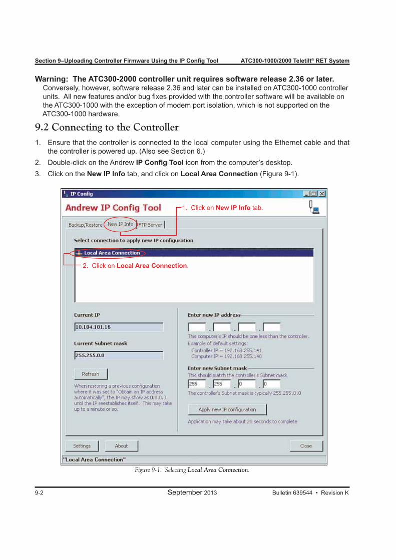
Section 9–Uploading Controller Firmware Using the IP Config Tool ATC300-1000/2000 Teletilt® RET System
9-2 September 2013 Bulletin 639544 • Revision K
Figure 9-1. Selecting Local Area Connection.
2. Click on Local Area Connection.
1. Click on New IP Info tab.
Warning: The ATC300-2000 controller unit requires software release 2.36 or later. Conversely, however, software release 2.36 and later can be installed on ATC300-1000 controller units. All new features and/or bug fixes provided with the controller software will be available on the ATC300-1000 with the exception of modem port isolation, which is not supported on the ATC300-1000 hardware.
9.2 Connecting to the Controller1. Ensure that the controller is connected to the local computer using the Ethernet cable and that
the controller is powered up. (Also see Section 6.)2. Double-click on the Andrew IP Config Tool icon from the computer’s desktop.3. Click on the New IP Info tab, and click on Local Area Connection (Figure 9-1).
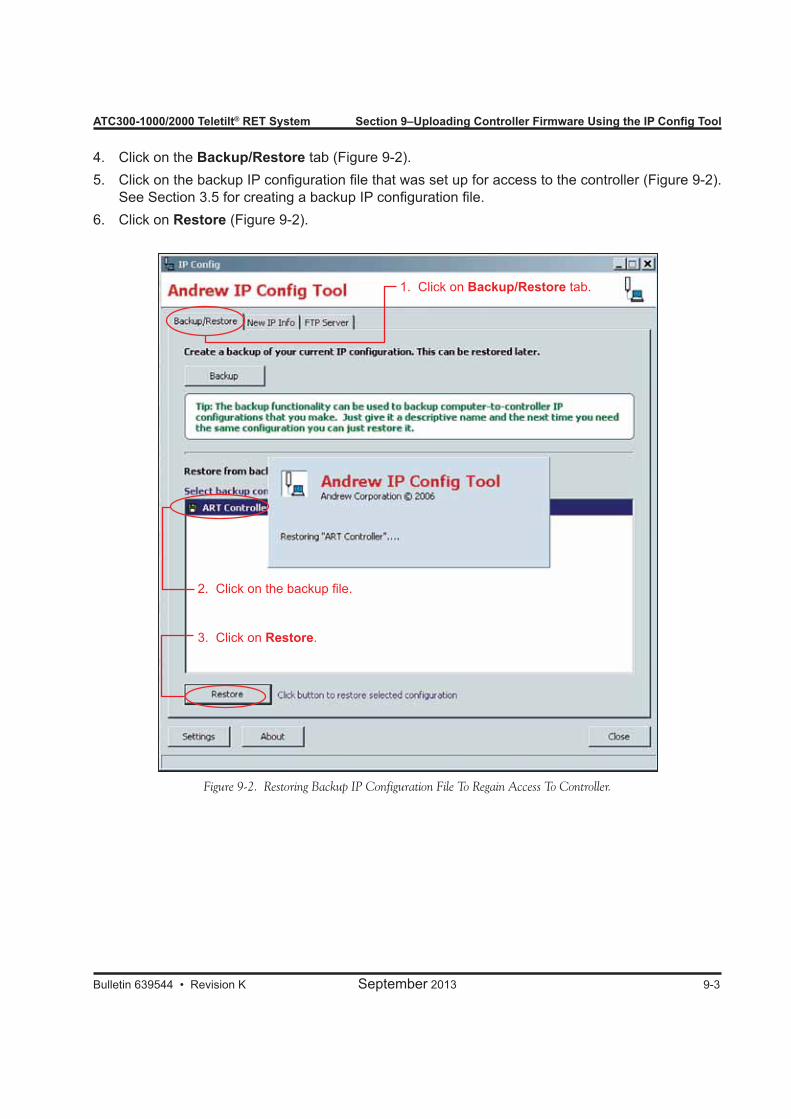
ATC300-1000/2000 Teletilt® RET System Section 9–Uploading Controller Firmware Using the IP Config Tool
Bulletin 639544 • Revision K September 2013 9-3
Figure 9-2. Restoring Backup IP Configuration File To Regain Access To Controller.
2. Click on the backup file.
3. Click on Restore.
1. Click on Backup/Restore tab.
4. Click on the Backup/Restore tab (Figure 9-2).5. Click on the backup IP configuration file that was set up for access to the controller (Figure 9-2).
See Section 3.5 for creating a backup IP configuration file.6. Click on Restore (Figure 9-2).
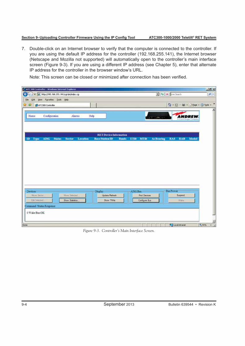
Section 9–Uploading Controller Firmware Using the IP Config Tool ATC300-1000/2000 Teletilt® RET System
9-4 September 2013 Bulletin 639544 • Revision K
Figure 9-3. Controller’s Main Interface Screen.
7. Double-click on an Internet browser to verify that the computer is connected to the controller. If you are using the default IP address for the controller (192.168.255.141), the Internet browser (Netscape and Mozilla not supported) will automatically open to the controller’s main interface screen (Figure 9-3). If you are using a different IP address (see Chapter 5), enter that alternate IP address for the controller in the browser window’s URL.
Note: This screen can be closed or minimized after connection has been verified.
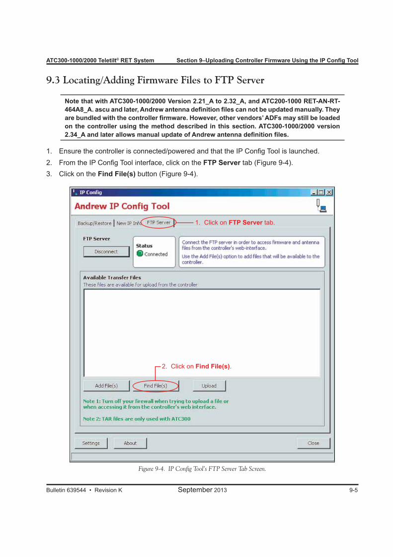
ATC300-1000/2000 Teletilt® RET System Section 9–Uploading Controller Firmware Using the IP Config Tool
Bulletin 639544 • Revision K September 2013 9-5
Figure 9-4. IP Config Tool’s FTP Server Tab Screen.
1. Click on FTP Server tab.
2. Click on Find File(s).
9.3 Locating/Adding Firmware Files to FTP Server
Note that with ATC300-1000/2000 Version 2.21_A to 2.32_A, and ATC200-1000 RET-AN-RT-464A8_A. ascu and later, Andrew antenna definition files can not be updated manually. They are bundled with the controller firmware. However, other vendors’ ADFs may still be loaded on the controller using the method described in this section. ATC300-1000/2000 version 2.34_A and later allows manual update of Andrew antenna definition files.
1. Ensure the controller is connected/powered and that the IP Config Tool is launched.2. From the IP Config Tool interface, click on the FTP Server tab (Figure 9-4).3. Click on the Find File(s) button (Figure 9-4).
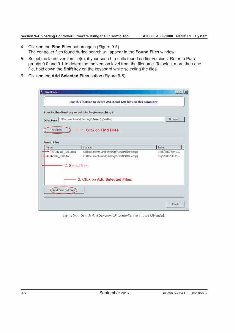
Section 9–Uploading Controller Firmware Using the IP Config Tool ATC300-1000/2000 Teletilt® RET System
9-6 September 2013 Bulletin 639544 • Revision K
Figure 9-5. Search And Selection Of Controller Files To Be Uploaded.
4. Click on the Find Files button again (Figure 9-5). The controller files found during search will appear in the Found Files window.5. Select the latest version file(s), if your search results found earlier versions. Refer to Para-
graphs 9.0 and 9.1 to determine the version level from the filename. To select more than one file, hold down the Shift key on the keyboard while selecting the files.
6. Click on the Add Selected Files button (Figure 9-5).
1. Click on Find Files.
2. Select files.
3. Click on Add Selected Files.
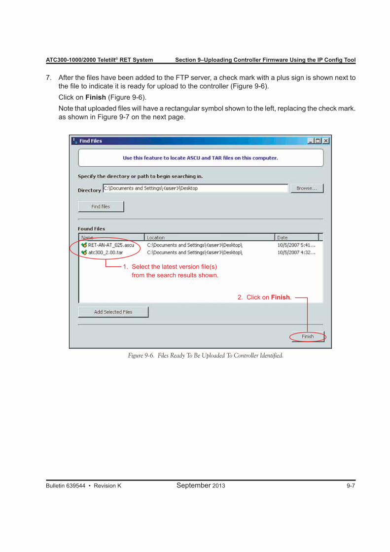
ATC300-1000/2000 Teletilt® RET System Section 9–Uploading Controller Firmware Using the IP Config Tool
Bulletin 639544 • Revision K September 2013 9-7
Figure 9-6. Files Ready To Be Uploaded To Controller Identified.
2. Click on Finish.
7. After the files have been added to the FTP server, a check mark with a plus sign is shown next to the file to indicate it is ready for upload to the controller (Figure 9-6).
Click on Finish (Figure 9-6). Note that uploaded files will have a rectangular symbol shown to the left, replacing the check mark.
as shown in Figure 9-7 on the next page.
1. Select the latest version file(s) from the search results shown.
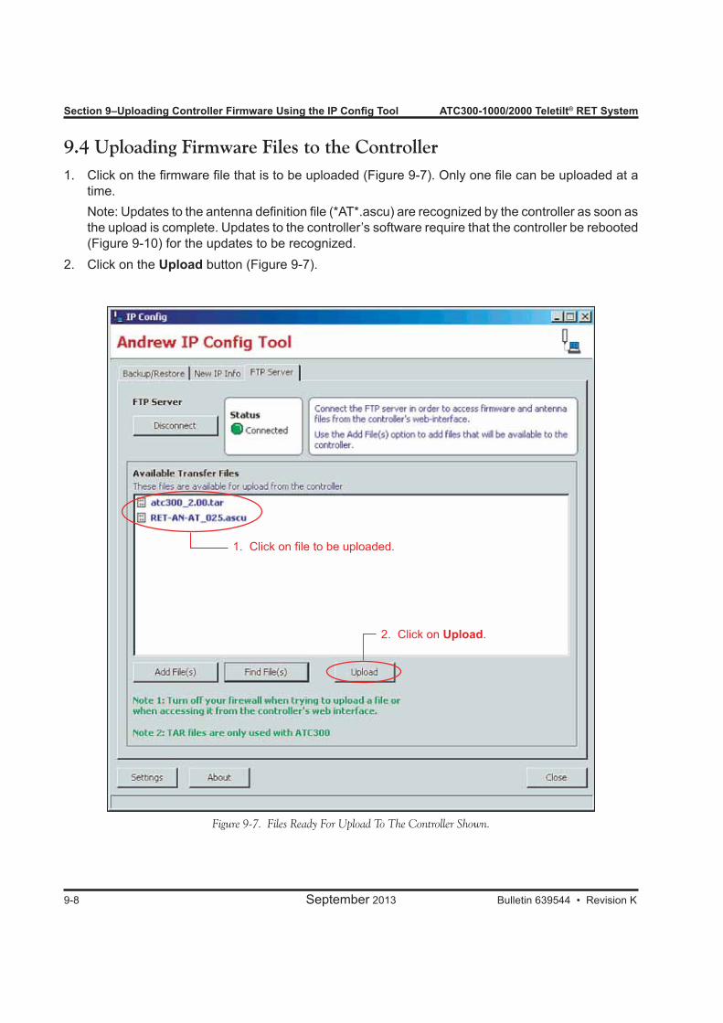
Section 9–Uploading Controller Firmware Using the IP Config Tool ATC300-1000/2000 Teletilt® RET System
9-8 September 2013 Bulletin 639544 • Revision K
Figure 9-7. Files Ready For Upload To The Controller Shown.
2. Click on Upload.
1. Click on file to be uploaded.
9.4 Uploading Firmware Files to the Controller1. Click on the firmware file that is to be uploaded (Figure 9-7). Only one file can be uploaded at a
time. Note: Updates to the antenna definition file (*AT*.ascu) are recognized by the controller as soon as
the upload is complete. Updates to the controller’s software require that the controller be rebooted (Figure 9-10) for the updates to be recognized.
2. Click on the Upload button (Figure 9-7).
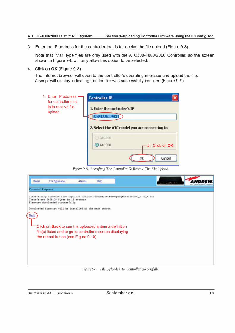
ATC300-1000/2000 Teletilt® RET System Section 9–Uploading Controller Firmware Using the IP Config Tool
Bulletin 639544 • Revision K September 2013 9-9
3. Enter the IP address for the controller that is to receive the file upload (Figure 9-8).
Note that ‘*.tar’ type files are only used with the ATC300-1000/2000 Controller, so the screen shown in Figure 9-8 will only allow this option to be selected.
4. Click on OK (Figure 9-8). The Internet browser will open to the controller’s operating interface and upload the file. A script will display indicating that the file was successfully installed (Figure 9-9).
Figure 9-8. Specifying The Controller To Receive The File Upload.
1. Enter IP address for controller that is to receive file upload.
2. Click on OK.
Figure 9-9. File Uploaded To Controller Successfully.
Click on Back to see the uploaded antenna definition file(s) listed and to go to controller’s screen displaying the reboot button (see Figure 9-10).
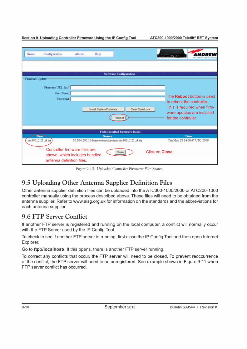
Section 9–Uploading Controller Firmware Using the IP Config Tool ATC300-1000/2000 Teletilt® RET System
9-10 September 2013 Bulletin 639544 • Revision K
Figure 9-10. Uploaded Controller Firmware Files Shown.
Controller firmware files are shown, which includes bundled antenna definition files.
The Reboot button is used to reboot the controller. This is required when firm-ware updates are installed for the controller.
9.5 Uploading Other Antenna Supplier Definition FilesOther antenna supplier definition files can be uploaded into the ATC300-1000/2000 or ATC200-1000 controller manually using the process described above. These files will need to be obtained from the antenna supplier. Refer to www.aisg.org.uk for information on the standards and the abbreviations for each antenna supplier.
9.6 FTP Server ConflictIf another FTP server is registered and running on the local computer, a conflict will normally occur with the FTP Server used by the IP Config Tool.To check to see if another FTP server is running, first close the IP Config Tool and then open Internet Explorer.Go to ftp://localhost/. If this opens, there is another FTP server running.To correct any conflicts that occur, the FTP server will need to be closed. To prevent reoccurrence of the conflict, the FTP server will need to be unregistered. See example shown in Figure 9-11 when FTP server conflict has occurred.
Click on Close.
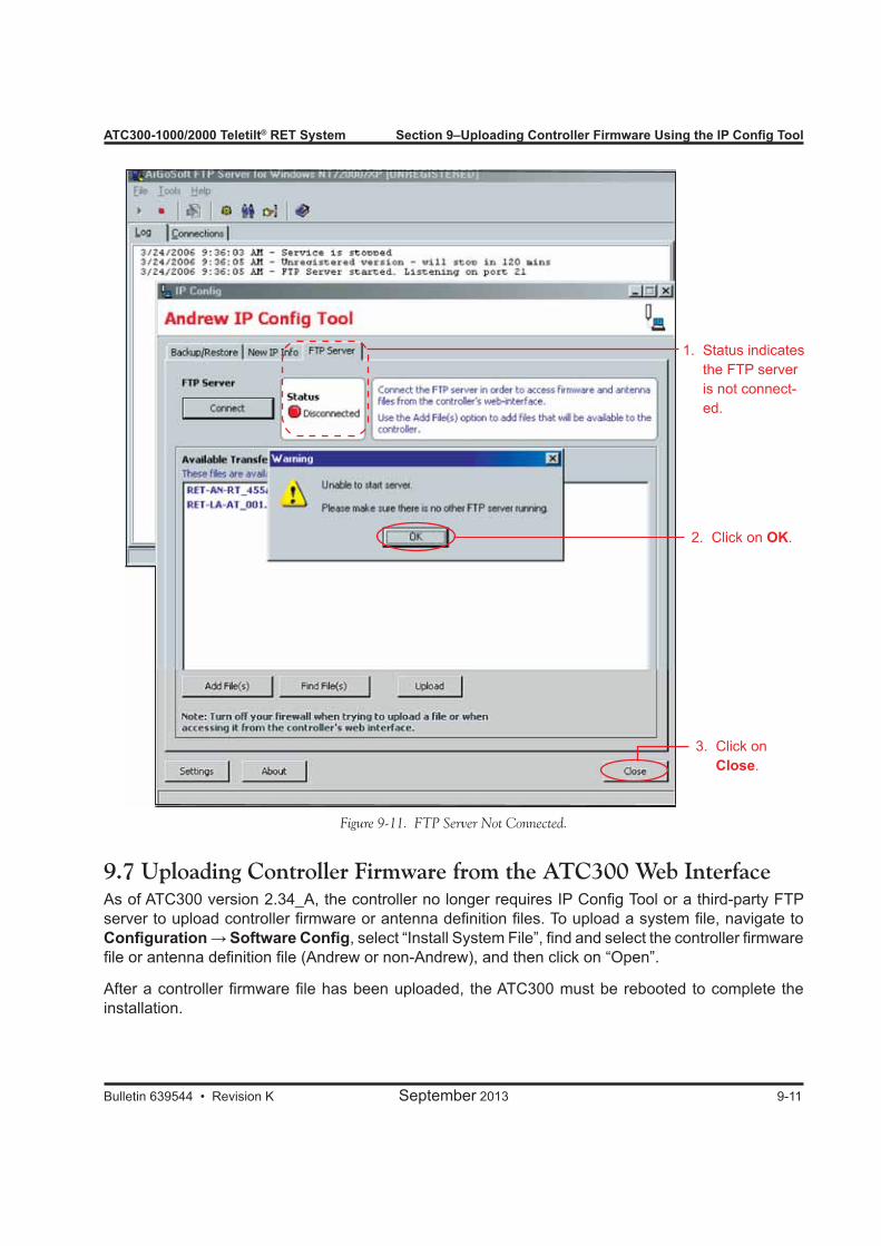
ATC300-1000/2000 Teletilt® RET System Section 9–Uploading Controller Firmware Using the IP Config Tool
Bulletin 639544 • Revision K September 2013 9-11
Figure 9-11. FTP Server Not Connected.
1. Status indicates the FTP server is not connect-ed.
2. Click on OK.
3. Click on Close.
9.7 Uploading Controller Firmware from the ATC300 Web InterfaceAs of ATC300 version 2.34_A, the controller no longer requires IP Config Tool or a third-party FTP server to upload controller firmware or antenna definition files. To upload a system file, navigate to Configuration → Software Config, select “Install System File”, find and select the controller firmware file or antenna definition file (Andrew or non-Andrew), and then click on “Open”.
After a controller firmware file has been uploaded, the ATC300 must be rebooted to complete the installation.
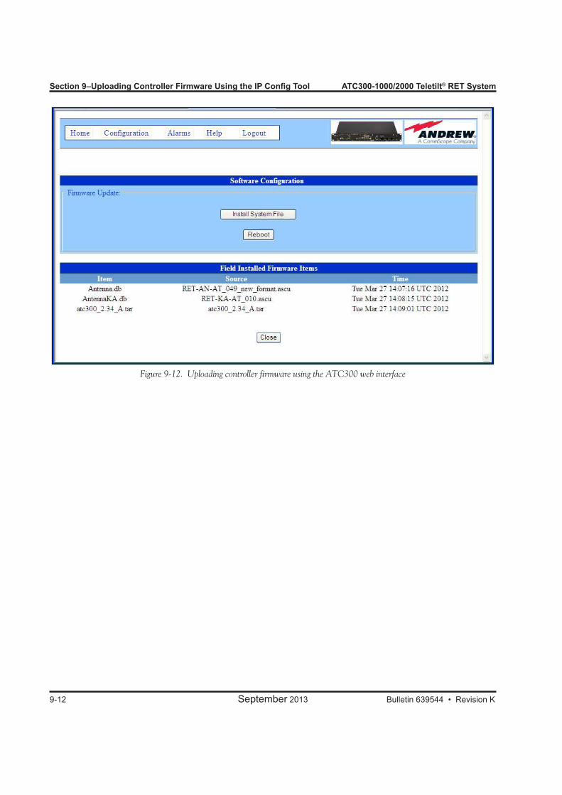
Section 9–Uploading Controller Firmware Using the IP Config Tool ATC300-1000/2000 Teletilt® RET System
9-12 September 2013 Bulletin 639544 • Revision K
Figure 9-12. Uploading controller firmware using the ATC300 web interface

ATC300-1000/2000 Teletilt® RET System Section 9–Uploading Controller Firmware Using the IP Config Tool
Bulletin 639544 • Revision K September 2013 9-13
This page intentionally left blank.
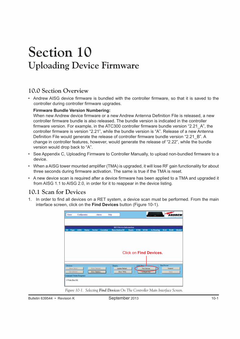
Bulletin 639544 • Revision K September 2013 10-1
Section 10Uploading Device Firmware
10.0 Section Overview• Andrew AISG device firmware is bundled with the controller firmware, so that it is saved to the
controller during controller firmware upgrades. Firmware Bundle Version Numbering:
When new Andrew device firmware or a new Andrew Antenna Definition File is released, a new controller firmware bundle is also released. The bundle version is indicated in the controller firmware version. For example, in the ATC300 controller firmware bundle version “2.21_A”, the controller firmware is version “2.21”, while the bundle version is “A”. Release of a new Antenna Definition File would generate the release of controller firmware bundle version “2.21_B”. A change in controller features, however, would generate the release of “2.22”, while the bundle version would drop back to “A”.
• See Appendix C, Uploading Firmware to Controller Manually, to upload non-bundled firmware to a device.
• When a AISG tower mounted amplifier (TMA) is upgraded, it will lose RF gain functionality for about three seconds during firmware activation. The same is true if the TMA is reset.
• A new device scan is required after a device firmware has been applied to a TMA and upgraded it from AISG 1.1 to AISG 2.0, in order for it to reappear in the device listing.
10.1 Scan for Devices1. In order to find all devices on a RET system, a device scan must be performed. From the main
interface screen, click on the Find Devices button (Figure 10-1).
Figure 10-1. Selecting Find Devices On The Controller Main Interface Screen.
Click on Find Devices.

Section 10–Uploading Device Firmware ATC300-1000/2000 Teletilt® RET System
10-2 September 2013 Bulletin 639544 • Revision K
Figure 10-2. ATC300-1000/2000 Controller Device Search Screen.
Click on Start Scan.
2. Click on the Start Scan button (Figure 10-2). The Device Search Progress window shows when the device search locates each device connected to the RET system.
10.2 Updating AISG Device FirmwareOperators can easily see the Update Required state of each device scanned on a RET system (Figure 10-3). The ATC300-1000/2000 controller shows each device in one of the following states:• A dashed line indicates a device that cannot be upgraded or that must be upgraded manually.
See Appendix C.• Unknown indicates that no firmware for that device has been installed on the controller.• Yes or No means the device does or does not require an upgrade to the latest device firmware.
1. When the device scan is complete, the Update Req’d field will display the current firmware status for each device. Figure 10-3 shows one TMA and three actuators that require updates.
2. Click on Update Devices (Figure 10-3).3. Only the devices in need of updates will appear on the Device Upgrades Recommended screen
(Figure 10-4). Some devices may take longer to update as noted in the Approx. Upgrade Time field.
4. Click on the Install Firmware button (Figure 10-4).

ATC300-1000/2000 Teletilt® RET System Section 10–Uploading Device Firmware
Bulletin 639544 • Revision K September 2013 10-3
Figure 10-3. Device Scan Results Show Updates Required.
Click onUpdate Devices.
Yes indicates devices that need updates.
Figure 10-4. Device Upgrades Recommended Screen.
Click on Install Firmware.
Approximate upgrade time is listed.
Unselect All option.
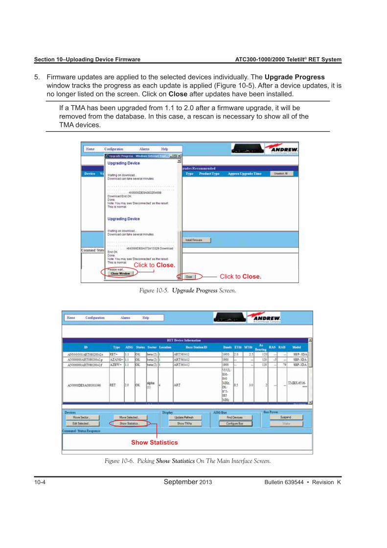
Section 10–Uploading Device Firmware ATC300-1000/2000 Teletilt® RET System
10-4 September 2013 Bulletin 639544 • Revision K
Figure 10-5. Upgrade Progress Screen.
Click to Close.
Click to Close.
5. Firmware updates are applied to the selected devices individually. The Upgrade Progress window tracks the progress as each update is applied (Figure 10-5). After a device updates, it is
no longer listed on the screen. Click on Close after updates have been installed.
If a TMA has been upgraded from 1.1 to 2.0 after a firmware upgrade, it will be removed from the database. In this case, a rescan is necessary to show all of the TMA devices.
Show Statistics
Figure 10-6. Picking Show Statistics On The Main Interface Screen.
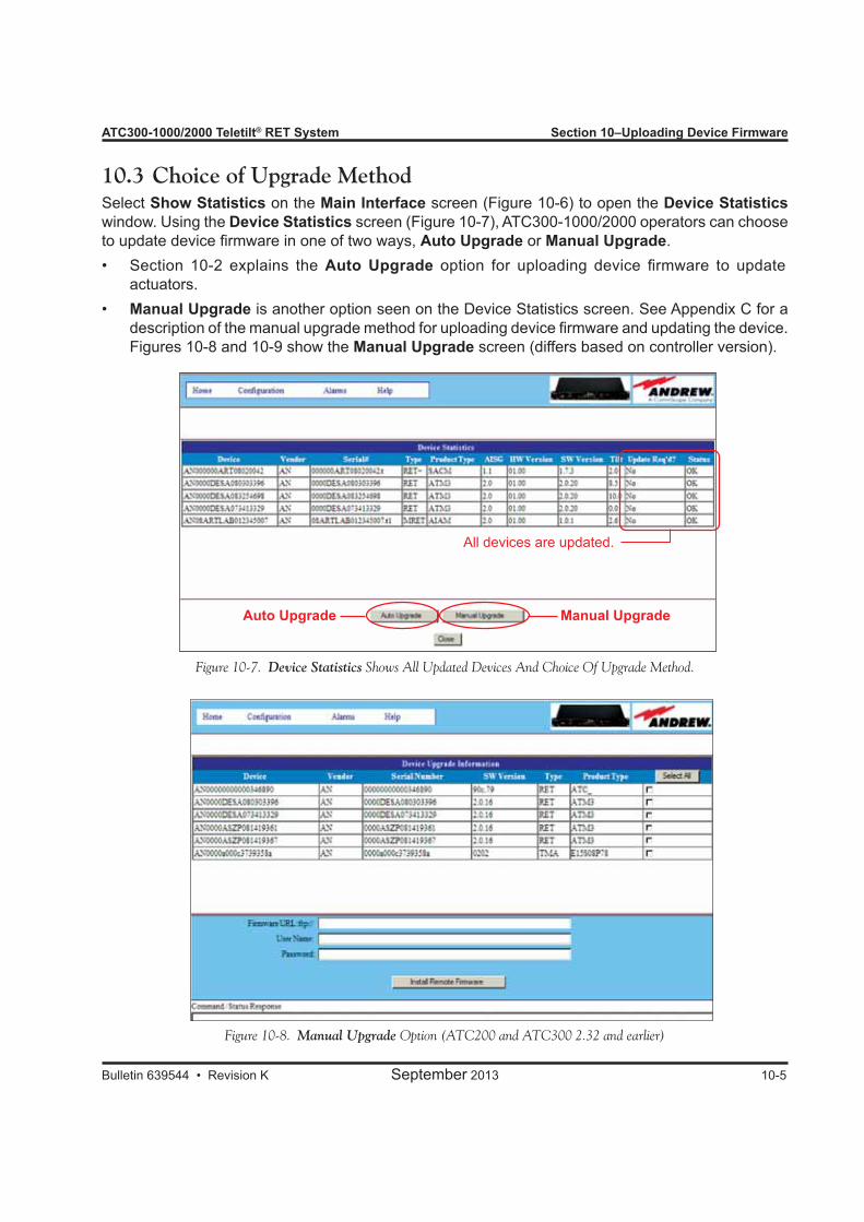
ATC300-1000/2000 Teletilt® RET System Section 10–Uploading Device Firmware
Bulletin 639544 • Revision K September 2013 10-5
10.3 Choice of Upgrade MethodSelect Show Statistics on the Main Interface screen (Figure 10-6) to open the Device Statistics window. Using the Device Statistics screen (Figure 10-7), ATC300-1000/2000 operators can choose to update device firmware in one of two ways, Auto Upgrade or Manual Upgrade.• Section 10-2 explains the Auto Upgrade option for uploading device firmware to update
actuators.• Manual Upgrade is another option seen on the Device Statistics screen. See Appendix C for a
description of the manual upgrade method for uploading device firmware and updating the device. Figures 10-8 and 10-9 show the Manual Upgrade screen (differs based on controller version).
Figure 10-7. Device Statistics Shows All Updated Devices And Choice Of Upgrade Method.
All devices are updated.
Manual UpgradeAuto Upgrade
Figure 10-8. Manual Upgrade Option (ATC200 and ATC300 2.32 and earlier)
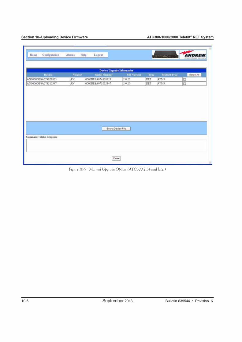
Section 10–Uploading Device Firmware ATC300-1000/2000 Teletilt® RET System
10-6 September 2013 Bulletin 639544 • Revision K
Figure 10-9 Manual Upgrade Option (ATC300 2.34 and later)
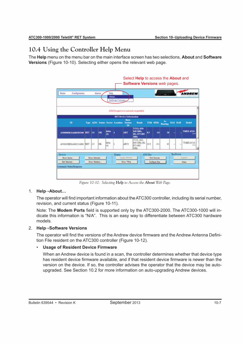
ATC300-1000/2000 Teletilt® RET System Section 10–Uploading Device Firmware
Bulletin 639544 • Revision K September 2013 10-7
Figure 10-10. Selecting Help to Access the About Web Page.
10.4 Using the Controller Help MenuThe Help menu on the menu bar on the main interface screen has two selections, About and Software Versions (Figure 10-10). Selecting either opens the relevant web page.
1. Help→About… The operator will find important information about the ATC300 controller, including its serial number,
revision, and current status (Figure 10-11). Note: The Modem Ports field is supported only by the ATC300-2000. The ATC300-1000 will in-
dicate this information is “N/A”. This is an easy way to differentiate between ATC300 hardware models.
2. Help→Software Versions The operator will find the versions of the Andrew device firmware and the Andrew Antenna Defini-
tion File resident on the ATC300 controller (Figure 10-12). • Usage of Resident Device Firmware
When an Andrew device is found in a scan, the controller determines whether that device type has resident device firmware available, and if that resident device firmware is newer than the version on the device. If so, the controller advises the operator that the device may be auto-upgraded. See Section 10.2 for more information on auto-upgrading Andrew devices.
Select Help to access the About and Software Versions web pages.
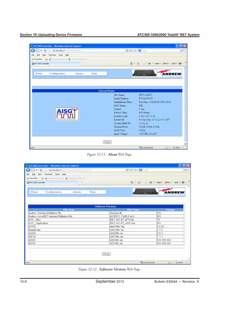
Section 10–Uploading Device Firmware ATC300-1000/2000 Teletilt® RET System
10-8 September 2013 Bulletin 639544 • Revision K
Figure 10-11. About Web Page.
Figure 10-12. Software Versions Web Page.

ATC300-1000/2000 Teletilt® RET System Section 10–Uploading Device Firmware
Bulletin 639544 • Revision K September 2013 10-9
This page is intentionally left blank.

Bulletin 639544 • Revision K September 2013
Part 4Device Discovery for All Types of
Antennas

Part 4–Device Discovery for All Types of Antennas ATC300-1000/2000 Teletilt® RET System
September 2013 Bulletin 639544 • Revision K
This page intentionally left blank.
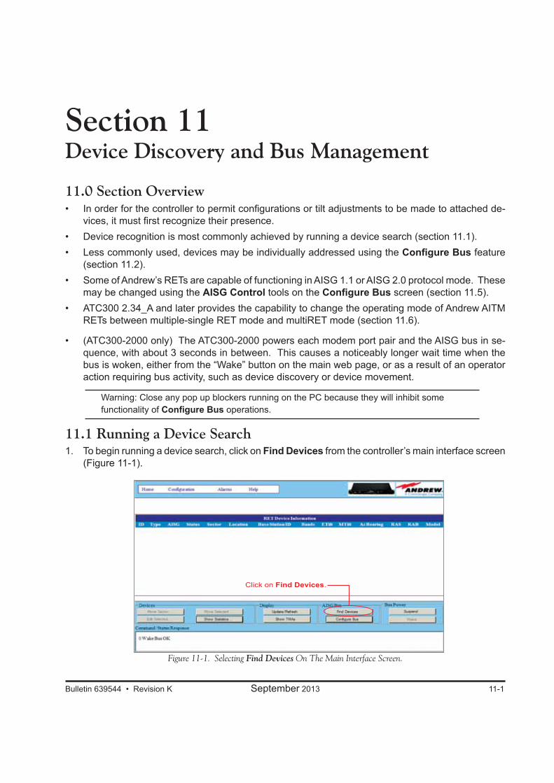
Bulletin 639544 • Revision K September 2013 11-1
Section 11Device Discovery and Bus Management
11.0 Section Overview• In order for the controller to permit configurations or tilt adjustments to be made to attached de-
vices, it must first recognize their presence. • Device recognition is most commonly achieved by running a device search (section 11.1). • Less commonly used, devices may be individually addressed using the Configure Bus feature
(section 11.2). • Some of Andrew’s RETs are capable of functioning in AISG 1.1 or AISG 2.0 protocol mode. These
may be changed using the AISG Control tools on the Configure Bus screen (section 11.5). • ATC300 2.34_A and later provides the capability to change the operating mode of Andrew AITM
RETs between multiple-single RET mode and multiRET mode (section 11.6).
• (ATC300-2000 only) The ATC300-2000 powers each modem port pair and the AISG bus in se-quence, with about 3 seconds in between. This causes a noticeably longer wait time when the bus is woken, either from the “Wake” button on the main web page, or as a result of an operator action requiring bus activity, such as device discovery or device movement.
Warning: Close any pop up blockers running on the PC because they will inhibit some functionality of Configure Bus operations.
11.1 Running a Device Search1. To begin running a device search, click on Find Devices from the controller’s main interface screen
(Figure 11-1).
Figure 11-1. Selecting Find Devices On The Main Interface Screen.
Click on Find Devices.

Section 11–Device Discovery and Addressing ATC300-1000/2000 Teletilt® RET System
11-2 September 2013 Bulletin 639544 • Revision K
2. Click on Start Scan to activate the device search (Figure 11-2). Note that the controller can identify up to 32 AISG devices.
• (ATC300 only) Device scan will allow up to 64 AISG devices in the database when the controller is configured as Bus is externally powered (See figure 7-3). Otherwise, the limit stays at 32.
3. After the device search is complete, click on Close to return to the controller’s main interface screen (Figure 11-3).
Figure 11-2. Starting Scan For New Devices.
Figure 11-3. Closing Device Search Results Screen.
After the scan is complete, click on Close.
Click on Start Scan.
Device scan is more efficient if operator selects the number of devices expected to be found. Leave at 32 if unknown.
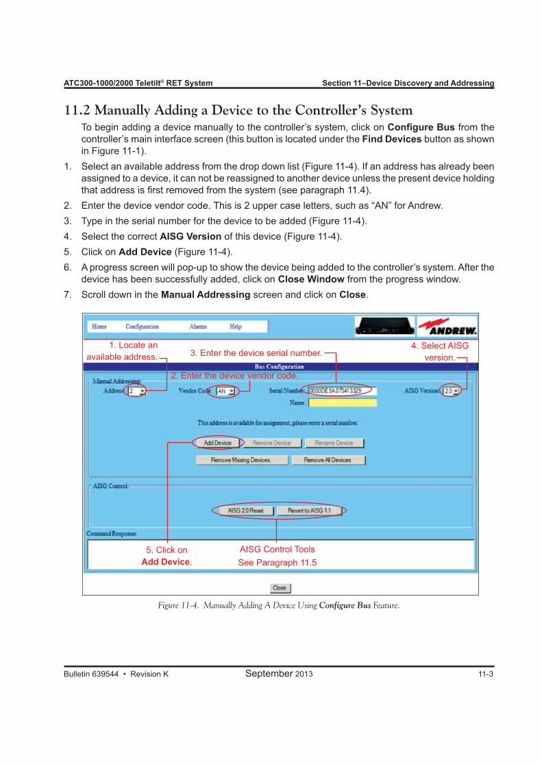
ATC300-1000/2000 Teletilt® RET System Section 11–Device Discovery and Addressing
Bulletin 639544 • Revision K September 2013 11-3
11.2 Manually Adding a Device to the Controller’s System To begin adding a device manually to the controller’s system, click on Configure Bus from the
controller’s main interface screen (this button is located under the Find Devices button as shown in Figure 11-1).
1. Select an available address from the drop down list (Figure 11-4). If an address has already been assigned to a device, it can not be reassigned to another device unless the present device holding that address is first removed from the system (see paragraph 11.4).
2. Enter the device vendor code. This is 2 upper case letters, such as “AN” for Andrew.3. Type in the serial number for the device to be added (Figure 11-4).4. Select the correct AISG Version of this device (Figure 11-4).5. Click on Add Device (Figure 11-4). 6. A progress screen will pop-up to show the device being added to the controller’s system. After the
device has been successfully added, click on Close Window from the progress window. 7. Scroll down in the Manual Addressing screen and click on Close.
Figure 11-4. Manually Adding A Device Using Configure Bus Feature.
1. Locate an available address. 3. Enter the device serial number.
2. Enter the device vendor code.
4. Select AISG version.
5. Click on Add Device.
AISG Control ToolsSee Paragraph 11.5
Section 11–Device Discovery and Addressing ATC300-1000/2000 Teletilt® RET System
11-4 September 2013 Bulletin 639544 • Revision K
11.3 AddressingNew devices are automatically assigned an address the first time they are found while running a device search. Addresses for devices that have previously been recognized through a device search are usually preserved during a new device scan, when possible.An address can be specified for a device using the Configure Bus feature that also allows a device to be manually added to the controller’s system (see paragraph 11.2). If a desired address is already taken, the serial number edit box will be grayed out–preventing any changes to be made. A device can be renamed, but this does not change the actual serial number already assigned to an address. Communication between the controller and the device is based upon the serial number that is em-bedded in the device and recognized in the controller. A device can be removed to make a specific address available for a different device and manually reloaded with a new address, if desired (see paragraph 11.4).
11.4 Removing a Device from the Controller’s SystemAfter a device has been recognized by the controller, either through a device search or manual setup, the controller’s system will continue to display its status and condition until it is explicitly told to remove the device. The controller’s database is not affected by power down and power up of the unit. When a device has been physically and permanently detached from the controller, it must be manually removed from the controller’s system to stop the controller from monitoring the device for status and alarms. 1. To begin removing a device from the controller’s system, click on the device from the controller’s
main screen to select it and then click on Configure Bus. The Configure Bus button is located under the Find Devices button in the lower portion of the screen as shown in Figure 11-1.
2. Verify that the correct serial number for the device that is to be removed shows in the Serial Number field (Figure 11-5).
3. Click on Remove Device (Figure 11-5).4. After the device is successfully removed, click on Close Window in the progress screen (Figure
11-6). 5. Scroll down in the Manual Addressing screen and click on Close (Figure 11-6).Note that there are also options to remove all devices or to remove all missing devices (Figure 11-5). Remove Missing Devices removes all devices from the controller database that are not currently communicating with the controller (or are in an “AISG_NO_REPLY” state).
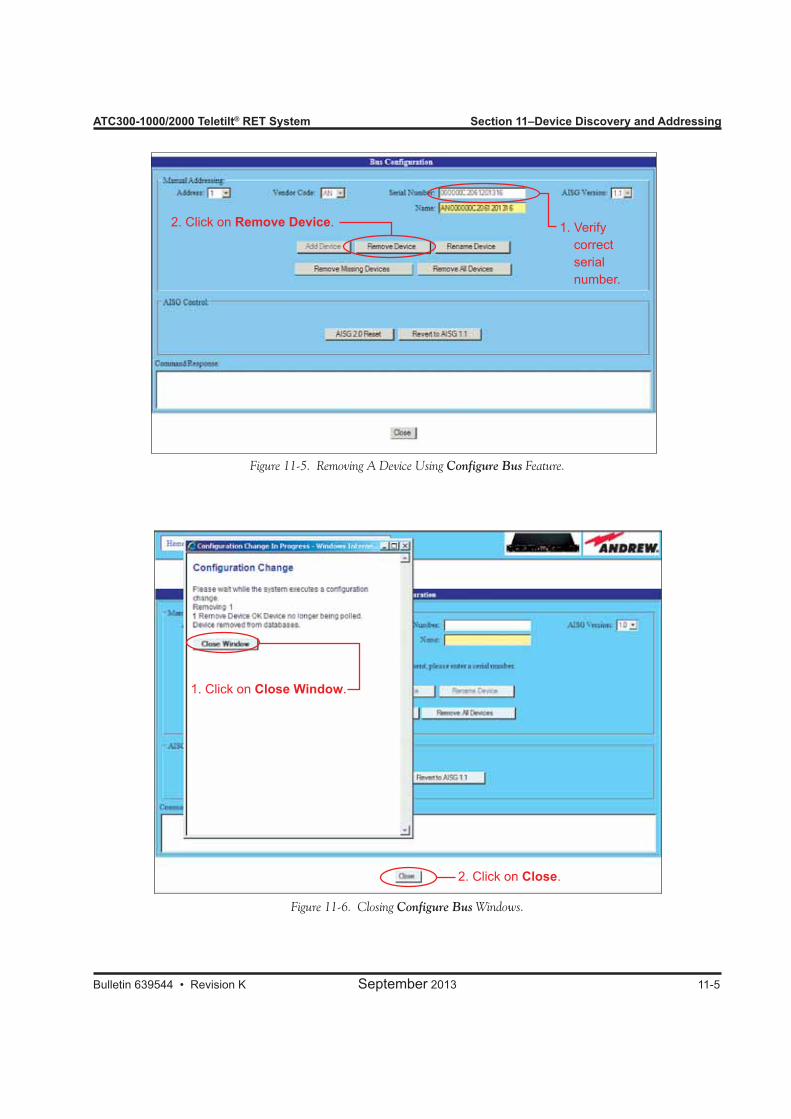
ATC300-1000/2000 Teletilt® RET System Section 11–Device Discovery and Addressing
Bulletin 639544 • Revision K September 2013 11-5
Figure 11-5. Removing A Device Using Configure Bus Feature.
Figure 11-6. Closing Configure Bus Windows.
1. Verify correct serial number.
2. Click on Remove Device.
1. Click on Close Window.
2. Click on Close.
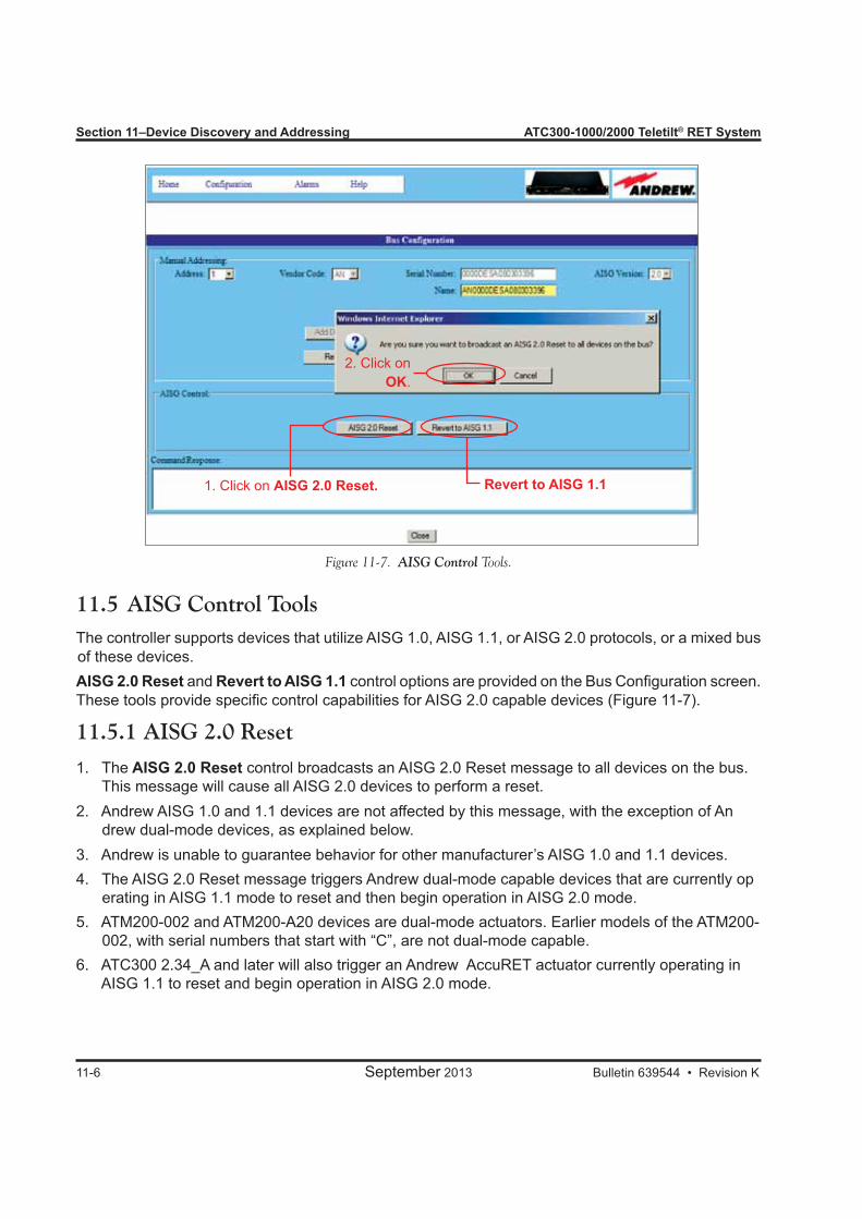
Section 11–Device Discovery and Addressing ATC300-1000/2000 Teletilt® RET System
11-6 September 2013 Bulletin 639544 • Revision K
Figure 11-7. AISG Control Tools.
11.5 AISG Control ToolsThe controller supports devices that utilize AISG 1.0, AISG 1.1, or AISG 2.0 protocols, or a mixed bus of these devices.AISG 2.0 Reset and Revert to AISG 1.1 control options are provided on the Bus Configuration screen. These tools provide specific control capabilities for AISG 2.0 capable devices (Figure 11-7).
11.5.1 AISG 2.0 Reset
1. The AISG 2.0 Reset control broadcasts an AISG 2.0 Reset message to all devices on the bus. This message will cause all AISG 2.0 devices to perform a reset.2. Andrew AISG 1.0 and 1.1 devices are not affected by this message, with the exception of An drew dual-mode devices, as explained below.3. Andrew is unable to guarantee behavior for other manufacturer’s AISG 1.0 and 1.1 devices.4. The AISG 2.0 Reset message triggers Andrew dual-mode capable devices that are currently op erating in AISG 1.1 mode to reset and then begin operation in AISG 2.0 mode.5. ATM200-002 and ATM200-A20 devices are dual-mode actuators. Earlier models of the ATM200- 002, with serial numbers that start with “C”, are not dual-mode capable.6. ATC300 2.34_A and later will also trigger an Andrew AccuRET actuator currently operating in AISG 1.1 to reset and begin operation in AISG 2.0 mode.
1. Click on AISG 2.0 Reset.
2. Click on OK.
Revert to AISG 1.1
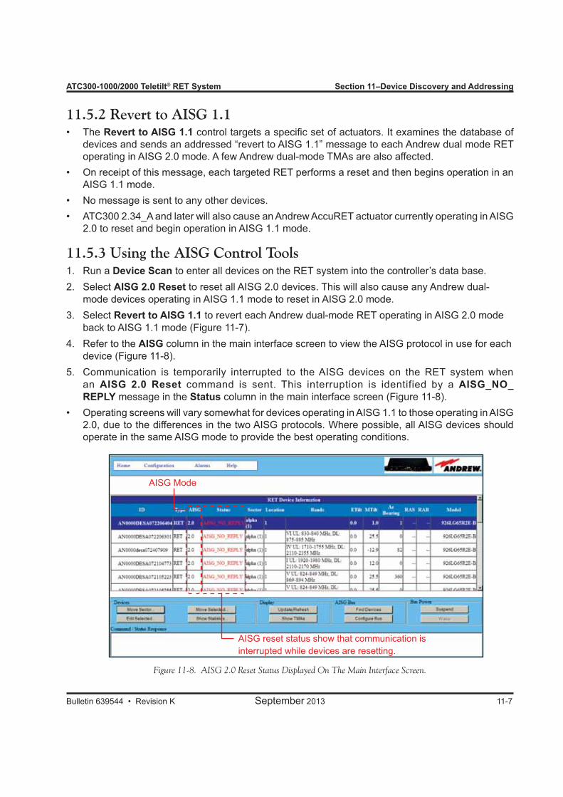
ATC300-1000/2000 Teletilt® RET System Section 11–Device Discovery and Addressing
Bulletin 639544 • Revision K September 2013 11-7
11.5.2 Revert to AISG 1.1• The Revert to AISG 1.1 control targets a specific set of actuators. It examines the database of
devices and sends an addressed “revert to AISG 1.1” message to each Andrew dual mode RET operating in AISG 2.0 mode. A few Andrew dual-mode TMAs are also affected.
• On receipt of this message, each targeted RET performs a reset and then begins operation in an AISG 1.1 mode.
• No message is sent to any other devices.• ATC300 2.34_A and later will also cause an Andrew AccuRET actuator currently operating in AISG
2.0 to reset and begin operation in AISG 1.1 mode.
11.5.3 Using the AISG Control ToolsRun a 1. Device Scan to enter all devices on the RET system into the controller’s data base.Select 2. AISG 2.0 Reset to reset all AISG 2.0 devices. This will also cause any Andrew dual-mode devices operating in AISG 1.1 mode to reset in AISG 2.0 mode.Select 3. Revert to AISG 1.1 to revert each Andrew dual-mode RET operating in AISG 2.0 mode back to AISG 1.1 mode (Figure 11-7).Refer to the 4. AISG column in the main interface screen to view the AISG protocol in use for each device (Figure 11-8).Communication is temporarily interrupted to the AISG devices on the RET system when 5. an AISG 2.0 Reset command is sent. This interruption is identified by a AISG_NO_ REPLY message in the Status column in the main interface screen (Figure 11-8).
• Operating screens will vary somewhat for devices operating in AISG 1.1 to those operating in AISG 2.0, due to the differences in the two AISG protocols. Where possible, all AISG devices should operate in the same AISG mode to provide the best operating conditions.
AISG reset status show that communication is interrupted while devices are resetting.
AISG Mode
Figure 11-8. AISG 2.0 Reset Status Displayed On The Main Interface Screen.

Section 11–Device Discovery and Addressing ATC300-1000/2000 Teletilt® RET System
11-8 September 2013 Bulletin 639544 • Revision K
Figure 11-9. Device Scan Results of an Andrew AITM Device in MultiRET Mode
11.6 Andrew AITM Actuator Mode Management (ATC300 2.34_A and
later only)As of version 2.34_A, the ATC300 controller Bus Configuration web page provides the capability to change the operating mode of Andrew AITM internal actuators between multiple-single RET mode and multiRET mode. This feature is targeted to this device type only, and will not be available unless one or more AITM devices have been discovered on the AISG bus.Note: The product type of devices can be found on the Statistics screen and the Find Devices screen. As an example, in Figure 11-9, this discovered device’s Product Type is “AITM” and the device Type is “MRET”, which indicates multiRET. An AITM in multiple-single RET mode would display an entry for each tilt, and would indicate a Type of “RET”.
When in multiRET mode, the internal actuators have one bus address, but support multiple tilts. The devices IDs have suffixes of “.t1”, “.t2”, etc. This mode is sometimes called “Type 17”, as this is the AISG-defined indication of a multiRET device.When in multiple-single RET mode, the internal actuators are assigned one bus address per tilt and act as independent actuators. The 19-character devices IDs end with “t1”, “t2”, etc. This mode is sometimes called “Type 1”, as this is the AISG-defined indication of a single RET device.
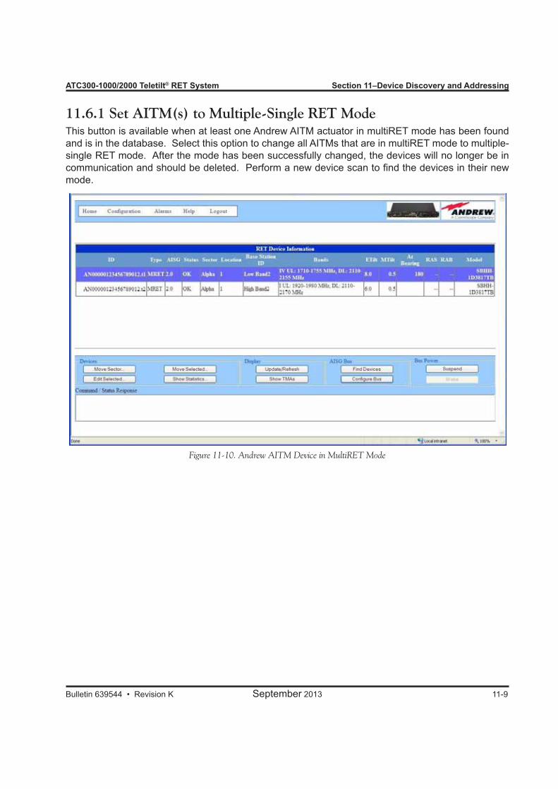
ATC300-1000/2000 Teletilt® RET System Section 11–Device Discovery and Addressing
Bulletin 639544 • Revision K September 2013 11-9
Figure 11-10. Andrew AITM Device in MultiRET Mode
11.6.1 Set AITM(s) to Multiple-Single RET ModeThis button is available when at least one Andrew AITM actuator in multiRET mode has been found and is in the database. Select this option to change all AITMs that are in multiRET mode to multiple-single RET mode. After the mode has been successfully changed, the devices will no longer be in communication and should be deleted. Perform a new device scan to find the devices in their new mode.
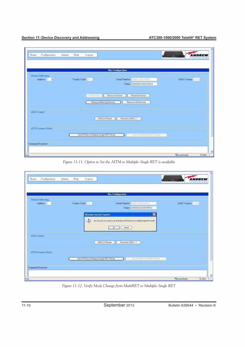
Section 11–Device Discovery and Addressing ATC300-1000/2000 Teletilt® RET System
11-10 September 2013 Bulletin 639544 • Revision K
Figure 11-11. Option to Set the AITM to Multiple-Single RET is available
Figure 11-12. Verify Mode Change from MultiRET to Multiple-Single RET

ATC300-1000/2000 Teletilt® RET System Section 11–Device Discovery and Addressing
Bulletin 639544 • Revision K September 2013 11-11
Figure 11-13. Successful Mode Change from MultiRET to Multiple-Single RET
Figure 11-14. Loss of Communication After Mode Change from MultiRET toMultiple-Single RET
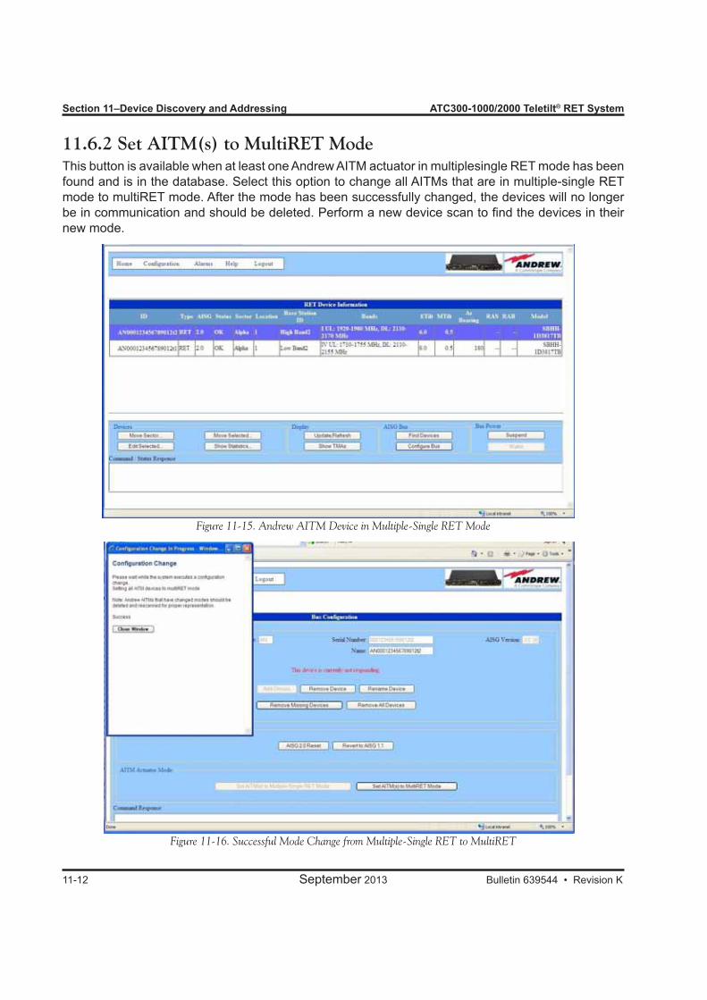
Section 11–Device Discovery and Addressing ATC300-1000/2000 Teletilt® RET System
11-12 September 2013 Bulletin 639544 • Revision K
11.6.2 Set AITM(s) to MultiRET ModeThis button is available when at least one Andrew AITM actuator in multiplesingle RET mode has been found and is in the database. Select this option to change all AITMs that are in multiple-single RET mode to multiRET mode. After the mode has been successfully changed, the devices will no longer be in communication and should be deleted. Perform a new device scan to find the devices in their new mode.
Figure 11-15. Andrew AITM Device in Multiple-Single RET Mode
Figure 11-16. Successful Mode Change from Multiple-Single RET to MultiRET

ATC300-1000/2000 Teletilt® RET System Section 11–Device Discovery and Addressing
Bulletin 639544 • Revision K September 2013 11-13
This page intentionally left blank.

Bulletin 639544 • Revision K September 2013
Part 5Operating Instructions for Standard Antennas with Attached Actuators

Part 5–Operating Instructions for Standard Antennas with Attached Actuators ATC300-1000/2000 Teletilt® RET System
September 2013 Bulletin 639544 • Revision K
This page intentionally left blank.
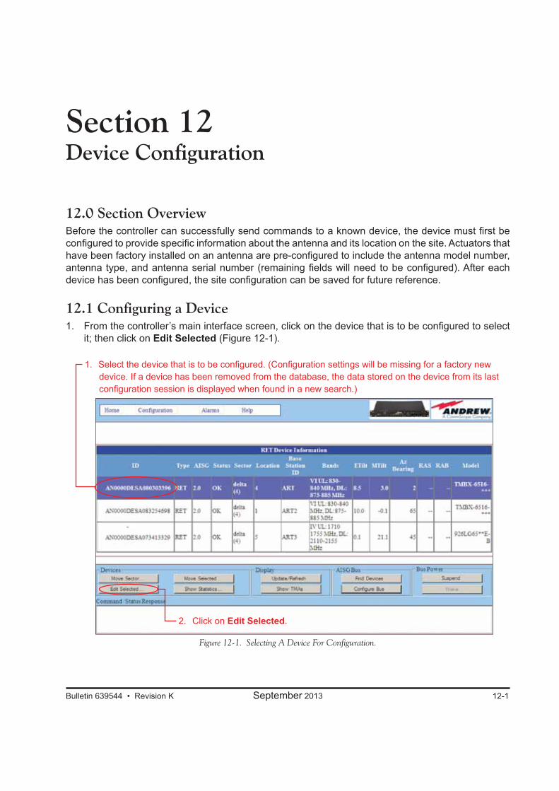
Bulletin 639544 • Revision K September 2013 12-1
Section 12Device Configuration
12.0 Section OverviewBefore the controller can successfully send commands to a known device, the device must first be configured to provide specific information about the antenna and its location on the site. Actuators that have been factory installed on an antenna are pre-configured to include the antenna model number, antenna type, and antenna serial number (remaining fields will need to be configured). After each device has been configured, the site configuration can be saved for future reference.
12.1 Configuring a Device1. From the controller’s main interface screen, click on the device that is to be configured to select
it; then click on Edit Selected (Figure 12-1).
Figure 12-1. Selecting A Device For Configuration.
2. Click on Edit Selected.
1. Select the device that is to be configured. (Configuration settings will be missing for a factory new device. If a device has been removed from the database, the data stored on the device from its last configuration session is displayed when found in a new search.)

Section 12–Device Configuration ATC300-1000/2000 Teletilt® RET System
12-2 September 2013 Bulletin 639544 • Revision K
Notice that the ID for the device that was selected from the main screen appears in the title bar of the Device Configuration screen. Required fields are marked with an asterisk. Saving a new configura-tion will not be permitted if any of the required fields are left blank or if values are out of range. Refer to Figure 12-2.2. Click on the drop down arrow to the right of Antenna Model, and select the antenna model that is
using the device. As of ACT300 firmware version 2.21_A, and ATC200 firmware version 464A8_A, the Andrew Antenna Definition File now groups the antenna models into logical “families”.
If no antenna models are available for selection, then an antenna definition file must be loaded on the controller. See Section 9.
This drop down list displays the Andrew base station antenna models that were defined in the latest antenna definition file.
Note that after an antenna model is selected, its minimum and maximum electrical down tilt range values are displayed just below the drop down list.
IMPORTANT The antenna model selected must match the actual installed antenna that is attached to the actuator (device). Movement data specific to this antenna will be sent to the actuator as a result of this selection. If the antenna model selected does not match the attached antenna, the movement range sent to the actuator will be incorrect and may prevent the antenna from functioning correctly. See paragraph 12.2 about the new generic antenna model naming protocol.
Figure 12-2. Configuring A New Device.
Fields marked with an asterisk must be configured.
Click on Set Device Data.Make appropriate selections and text entries. (All configuration data is stored in the individual device.)
RET device ID shown.
Click on Close.
ATC300-1000/2000 Teletilt® RET System Section 12–Device Configuration
Bulletin 639544 • Revision K September 2013 12-3
Factory installed actuators are pre-configured to include the antenna model number, antenna type, and antenna serial number it is operating.
3. Click on the drop down arrow to the right of Antenna Type, and select the type of antenna that is correct for the antenna model you selected. Note that this value is used for reference only and has no direct affect upon the Actuator/Antenna that is being configured.
4. Enter the serial number of the antenna that is attached to this device in the Antenna Serial # field. Note that this field is optional. However, if it is entered, it must be from 1 to 17 characters in length and it may contain any combination of letters and numbers.
5. Specify the parameters for the remaining fields (Frequency Band, Technology, Base Station ID, Installer ID, Installation Date, Mechanical Tilt, Bearing, Height, Sector, Location).
Note the following: • The fields of Antenna Type, Technology, Location, and Height are available for Andrew
non-TMA devices only. • A positive mechanical tilt angle means that the antenna beam is directed below the
horizontal plane. A negative mechanical tilt angle means that the antenna beam is directed above the horizontal plane.
• The Bearing is the installed compass orientation for this antenna. • The Height of the antenna up the tower must be entered in the range of 1 to 999.
No specific unit of length, such as feet or meters, is associated with this field. However, you should enter a value that conforms to the units of length customarily used by your company for antenna installations.
• The ID for the base station associated with this antenna must be 1 to 12 characters in length for AISG 1.x devices and 1-32 characters in length for AISG 2.0 devices, and may contain any combination of numbers and letters.
• The Installation Date field must be 1 to 6 characters in length with any combination of letters and numbers.
• The Installer ID must be 1 to 5 characters in length with any combination of letters and numbers.
• The Location field is a string with a numeric value from 1 to 32 that describes an actuator’s position within a sector. Each device should have a unique sector-location combination.
• Mechanical tilt has a valid range of -12.8 to 12.7 in AISG 1.1, and ±180.0 in AISG 2.0. • Values specified for the Frequency Band, Technology, and Mechanical
Tilt are used for reference only and have no direct affect upon the actuator/ antenna that is being configured.
6. Carefully review all selections. If satisfied that all are correct, click on Set Device Data. Alternately, the user may go back and edit/change any of the selections made or click on Close to quit this process without making any changes to the actuator’s current configuration.
7. Click on Close after the new settings have finished uploading to the device (Figure 12-2).8. If the device was successfully configured, the status will indicate the device is OK on the main
screen. Note that not all of the items that were configured are displayed on the main screen (Figure 12-3).
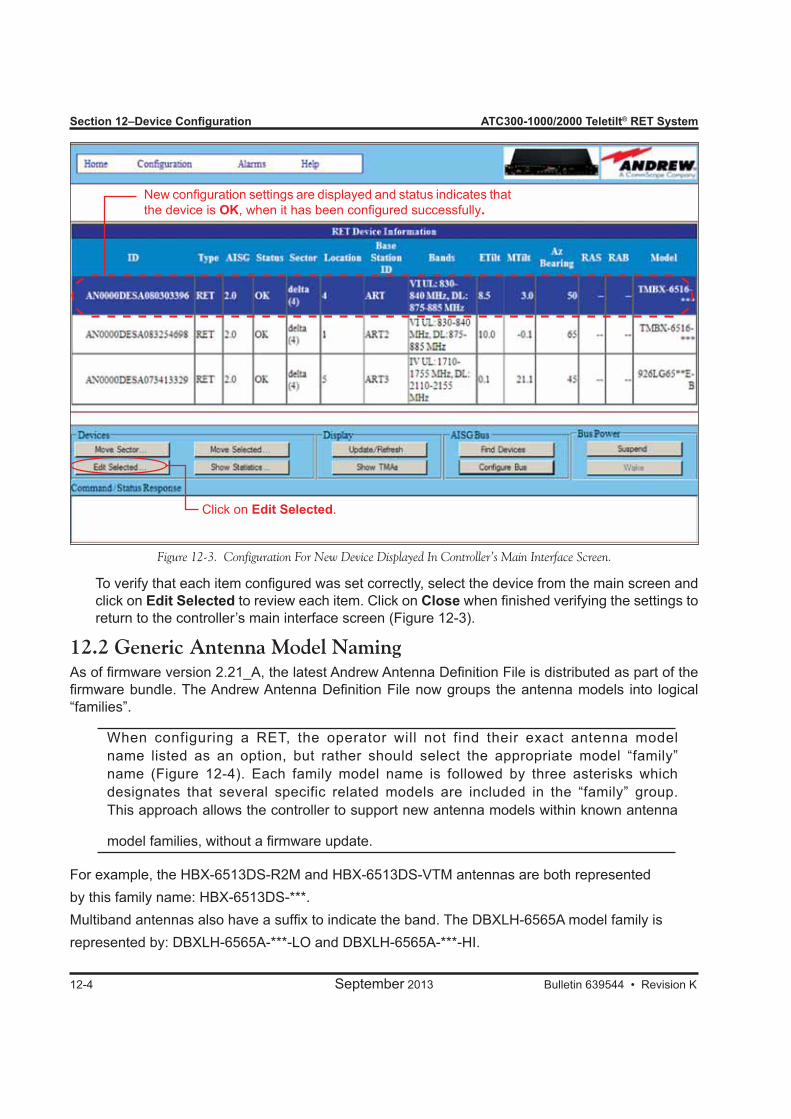
Section 12–Device Configuration ATC300-1000/2000 Teletilt® RET System
12-4 September 2013 Bulletin 639544 • Revision K
To verify that each item configured was set correctly, select the device from the main screen and click on Edit Selected to review each item. Click on Close when finished verifying the settings to return to the controller’s main interface screen (Figure 12-3).
12.2 Generic Antenna Model NamingAs of firmware version 2.21_A, the latest Andrew Antenna Definition File is distributed as part of the firmware bundle. The Andrew Antenna Definition File now groups the antenna models into logical “families”.
When configuring a RET, the operator will not find their exact antenna model name listed as an option, but rather should select the appropriate model “family” name (Figure 12-4). Each family model name is followed by three asterisks which designates that several specific related models are included in the “family” group. This approach allows the controller to support new antenna models within known antenna
model families, without a firmware update.
For example, the HBX-6513DS-R2M and HBX-6513DS-VTM antennas are both representedby this family name: HBX-6513DS-***.Multiband antennas also have a suffix to indicate the band. The DBXLH-6565A model family isrepresented by: DBXLH-6565A-***-LO and DBXLH-6565A-***-HI.
Figure 12-3. Configuration For New Device Displayed In Controller’s Main Interface Screen.
Click on Edit Selected.
New configuration settings are displayed and status indicates that the device is OK, when it has been configured successfully.
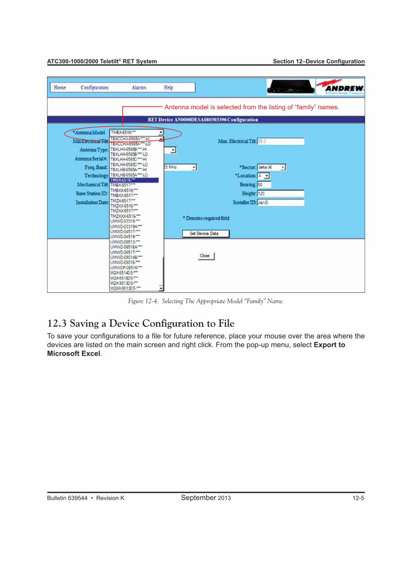
ATC300-1000/2000 Teletilt® RET System Section 12–Device Configuration
Bulletin 639544 • Revision K September 2013 12-5
12.3 Saving a Device Configuration to FileTo save your configurations to a file for future reference, place your mouse over the area where the devices are listed on the main screen and right click. From the pop-up menu, select Export to Microsoft Excel.
Figure 12-4. Selecting The Appropriate Model “Family” Name.
Antenna model is selected from the listing of “family” names.

Section 12–Device Configuration ATC300-1000/2000 Teletilt® RET System
12-6 September 2013 Bulletin 639544 • Revision K
This page intentionally left blank.

Bulletin 639544 • Revision K September 2013 13-1
Section 13Adjusting the Electrical Downtilt on a Single Antenna13.0 Section Overview• The electrical downtilt may be adjusted on any device that is addressed, configured, and whose
current state does not prevent antenna movement. • Movement may be prevented when a device is not responding to commands from the controller, is
in the middle of a move or configuration change, or is experiencing a mechanical malfunction.
13.1 Adjusting the Downtilt Angle on a Single Antenna1. From the controller’s main interface screen, select the device to be moved (Figure 13-1).2. Click on Move Selected (Figure 13-1).
Figure 13-1. Selecting Device To Be Adjusted.
1. Click on the device that is to be adjusted.
2. Click on Move Selected.

Section 13–Adjusting the Electrical Downtilt on a Single Antenna ATC300-1000/2000 Teletilt® RET System
13-2 September 2013 Bulletin 639544 • Revision K
The RET Device Movement screen shown in Figure 13-2 displays the information that was previously configured for the device. This information may be used as a reference to help determine the new tilt setting. Note that only tilt changes may be made from this screen. Any changes needed to be made to the configuration for the device must be done from the Device Configuration screen as discussed in Section 12.3. Enter the new angle for the device in the Set Tilt field. Note that the allowed range of angle values
is displayed in the Min Electrical Tilt and Max Electrical Tilt fields in the top part of the screen. Any downtilt angle within this range may be entered. Angles may be entered as whole degrees, or as a combination of whole degrees and tenths of a degree (Figure 13-2).
Examples: Five degrees downtilt may be entered as 5 or 5.0. A downtilt of five and one-half de-grees would be entered as 5.5.
4. Click on Set Tilt to apply the changes to the electrical downtilt for this antenna. Alternately, to exit the screen without sending any changes, click on Close.
Figure 13-2. Changing Electrical Tilt Setting For Single Antenna.
1. Review the electrical tilt range to verify that the new tilt angle will be valid for the antenna model.
2. Enter the new electrical tilt angle. Angles may be entered as whole degrees or as a combination of whole degrees and tenths of a degree (Ex: 5.0 or 5.5).
3. Click on Set Tilt.
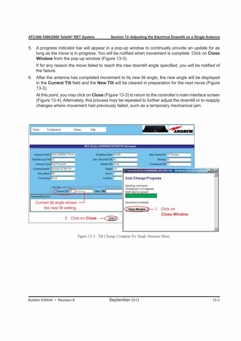
ATC300-1000/2000 Teletilt® RET System Section 13–Adjusting the Electrical Downtilt on a Single Antenna
Bulletin 639544 • Revision K September 2013 13-3
5. A progress indicator bar will appear in a pop-up window to continually provide an update for as long as the move is in progress. You will be notified when movement is complete. Click on Close Window from the pop-up window (Figure 13-3).
If for any reason the move failed to reach the new downtilt angle specified, you will be notified of the failure.
6. After the antenna has completed movement to its new tilt angle, the new angle will be displayed in the Current Tilt field and the New Tilt will be cleared in preparation for the next move (Figure 13-3).
At this point, you may click on Close (Figure 13-3) to return to the controller’s main interface screen (Figure 13-4). Alternately, this process may be repeated to further adjust the downtilt or to reapply changes where movement had previously failed, such as a temporary mechanical jam.
Figure 13-3. Tilt Change Complete For Single Antenna Move.
1. Click on Close Window.
2. Click on Close.
Current tilt angle shows the new tilt setting.
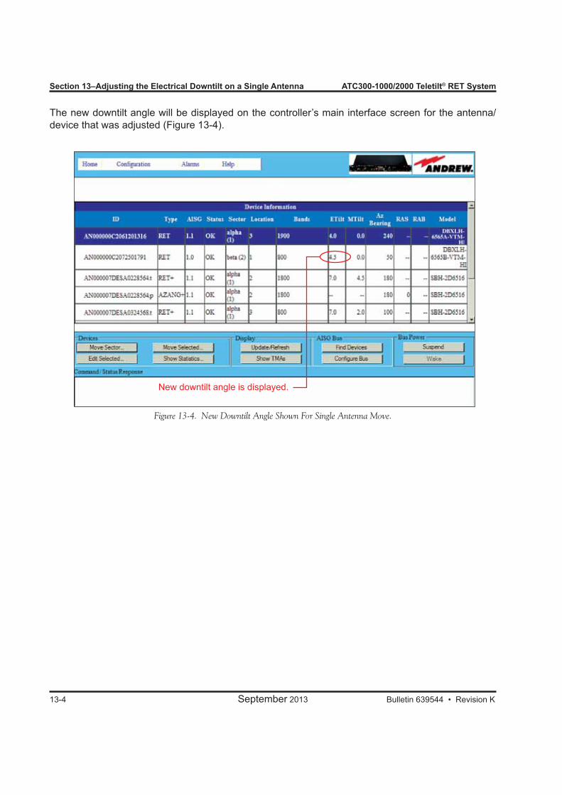
Section 13–Adjusting the Electrical Downtilt on a Single Antenna ATC300-1000/2000 Teletilt® RET System
13-4 September 2013 Bulletin 639544 • Revision K
Figure 13-4. New Downtilt Angle Shown For Single Antenna Move.
New downtilt angle is displayed.
The new downtilt angle will be displayed on the controller’s main interface screen for the antenna/device that was adjusted (Figure 13-4).

Bulletin 639544 • Revision K September 2013 14-1
Section 14Adjusting the Electrical Downtilt on a Group of Antennas
14.0 Section OverviewIn addition to changing the downtilt of a single antenna, changes may also be applied to a group of antennas. The antennas that can be included in a group move must be in the same sector and have the same electrical tilt range (same minimum and maximum tilt) and be the same device type.
14.1 Adjusting the Downtilt Angle on a Group of Antennas1. Select a device from the controller’s main interface screen that is to be included in the sector move
(Figure 14-1). 2. Click on Move Sector (Figure 14-1).
Figure 14-1. Selecting A Device That Is To Be Included In The Sector Move.
1. Click on a device that is to be included in the sector move.
2. Click on Move Sector.

Section 14–Adjusting the Electrical Downtilt on a Group of Antennas ATC300-1000/2000 Teletilt® RET System
14-2 September 2013 Bulletin 639544 • Revision K
Figure 14-2. Adding Models To Be Included In The Sector Move.
Notice that the device that was selected to be included in the sector move is highlighted and displayed in the Included box. This box displays a list of all devices that will be included in the sector move. Ini-tially, this box contains only the antenna that was selected from the controller’s main interface screen. The minimum, maximum, and current tilt for this device is displayed on this screen (Figure 14-2).Other devices that have the same sector ID, minimum tilt, and maximum tilt are listed in the Additional box. If desired, the configuration settings can be viewed for each device before adding them to the sec-tor group to be moved. Click on each model individually to view the configurations for each device.Note that up to 12 antenna/device pairs may be selected for a sector move. Any more than 12 will be denied when attempting to add to the group for inclusion in the move.3. Select the device, and click on Add (Figure 14-2). (Alternately, double-click on the device from
the Additional box to move the device to the Included box.)4. Examine the group selected for the sector move (shown in the Included box), to ensure that the
group does not include any antennas that are not desired for this move. If you find that a device is not wanted for inclusion in the sector move, click on the device, and click on Remove. (Alternately, double-click on the device to remove it from the group.)
5. When satisfied with the list of antennas that will be included in the group move, enter a new downtilt angle in the New Tilt text entry field, and click on Set Tilt to begin the move (Figure 14-3). Progress for each antenna movement in the group will be displayed separately (Figure 14-4).
6. You will be notified when all antennas have successfully reached the new tilt angle. Click on Close Window from the pop-up window (Figure 14-4).
7. The new angle will be displayed in the Current Tilt field and the New Tilt field will be cleared. If further adjustments are needed, they may be done before exiting this screen. When the desired adjustments are complete, click on Close (Figure 14-4) to return to the controller’s main interface screen (Figure 14-5).
2. Click on Add.
1. Click on the additional models, one at a time, to be included in the sector move. (Double-clicking on the model will also add it to the group for the sector move.)
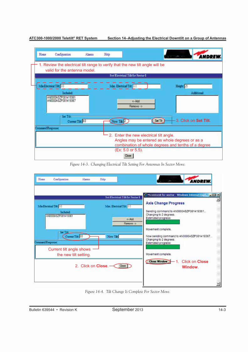
ATC300-1000/2000 Teletilt® RET System Section 14–Adjusting the Electrical Downtilt on a Group of Antennas
Bulletin 639544 • Revision K September 2013 14-3
2. Click on Close.1. Click on Close
Window.
Current tilt angle shows the new tilt setting.
Figure 14-3. Changing Electrical Tilt Setting For Antennas In Sector Move.
Figure 14-4. Tilt Change Is Complete For Sector Move.
2. Enter the new electrical tilt angle. Angles may be entered as whole degrees or as a combination of whole degrees and tenths of a degree (Ex: 5.0 or 5.5).
1. Review the electrical tilt range to verify that the new tilt angle will be valid for the antenna model.
3. Click on Set Tilt.
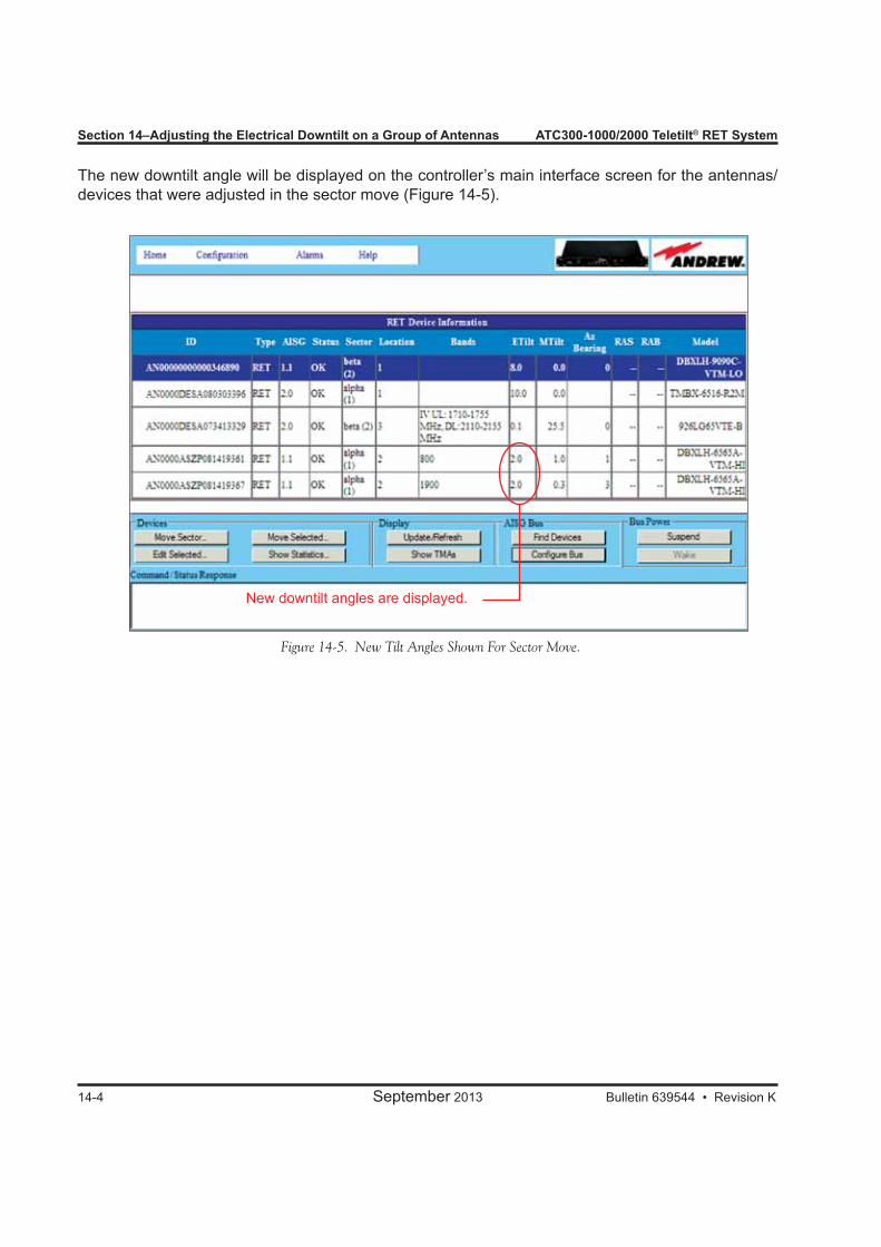
Section 14–Adjusting the Electrical Downtilt on a Group of Antennas ATC300-1000/2000 Teletilt® RET System
14-4 September 2013 Bulletin 639544 • Revision K
Figure 14-5. New Tilt Angles Shown For Sector Move.
New downtilt angles are displayed.
The new downtilt angle will be displayed on the controller’s main interface screen for the antennas/devices that were adjusted in the sector move (Figure 14-5).
Bulletin 639544 • Revision K September 2013
Part 6Operating Instructions for Antennas with Multiple Integrated Actuators

Part 6–Operating Antennas with Multiple Integrating Actuators
September 2013 Bulletin 639544 • Revision K
ATC300-1000/2000 Teletilt® RET System
This page intentionally left blank.
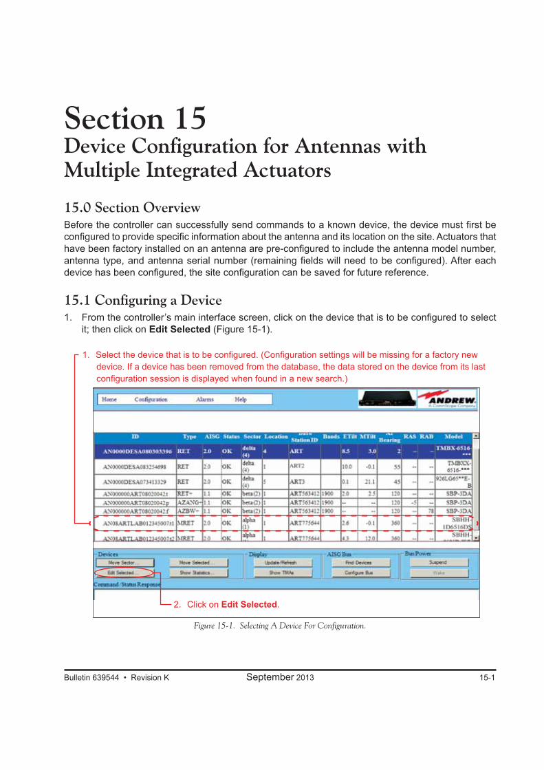
Bulletin 639544 • Revision K September 2013 15-1
Section 15Device Configuration for Antennas with Multiple Integrated Actuators
15.0 Section OverviewBefore the controller can successfully send commands to a known device, the device must first be configured to provide specific information about the antenna and its location on the site. Actuators that have been factory installed on an antenna are pre-configured to include the antenna model number, antenna type, and antenna serial number (remaining fields will need to be configured). After each device has been configured, the site configuration can be saved for future reference.
15.1 Configuring a Device1. From the controller’s main interface screen, click on the device that is to be configured to select
it; then click on Edit Selected (Figure 15-1).
Figure 15-1. Selecting A Device For Configuration.
2. Click on Edit Selected.
1. Select the device that is to be configured. (Configuration settings will be missing for a factory new device. If a device has been removed from the database, the data stored on the device from its last configuration session is displayed when found in a new search.)
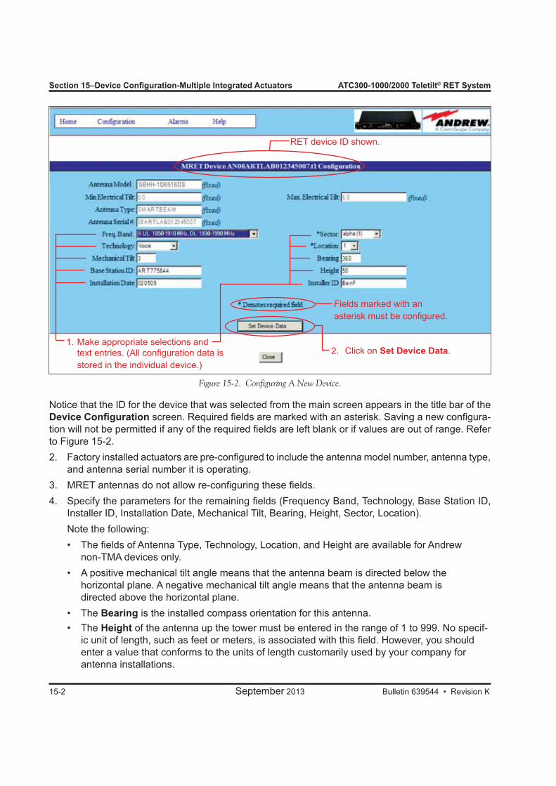
Section 15–Device Configuration-Multiple Integrated Actuators ATC300-1000/2000 Teletilt® RET System
15-2 September 2013 Bulletin 639544 • Revision K
Notice that the ID for the device that was selected from the main screen appears in the title bar of the Device Configuration screen. Required fields are marked with an asterisk. Saving a new configura-tion will not be permitted if any of the required fields are left blank or if values are out of range. Refer to Figure 15-2.2. Factory installed actuators are pre-configured to include the antenna model number, antenna type,
and antenna serial number it is operating.3. MRET antennas do not allow re-configuring these fields.4. Specify the parameters for the remaining fields (Frequency Band, Technology, Base Station ID,
Installer ID, Installation Date, Mechanical Tilt, Bearing, Height, Sector, Location). Note the following: • The fields of Antenna Type, Technology, Location, and Height are available for Andrew
non-TMA devices only. • A positive mechanical tilt angle means that the antenna beam is directed below the
horizontal plane. A negative mechanical tilt angle means that the antenna beam is directed above the horizontal plane.
• The Bearing is the installed compass orientation for this antenna. • The Height of the antenna up the tower must be entered in the range of 1 to 999. No specif-
ic unit of length, such as feet or meters, is associated with this field. However, you should enter a value that conforms to the units of length customarily used by your company for antenna installations.
Figure 15-2. Configuring A New Device.
Fields marked with an asterisk must be configured.
2. Click on Set Device Data.1. Make appropriate selections and
text entries. (All configuration data is stored in the individual device.)
RET device ID shown.
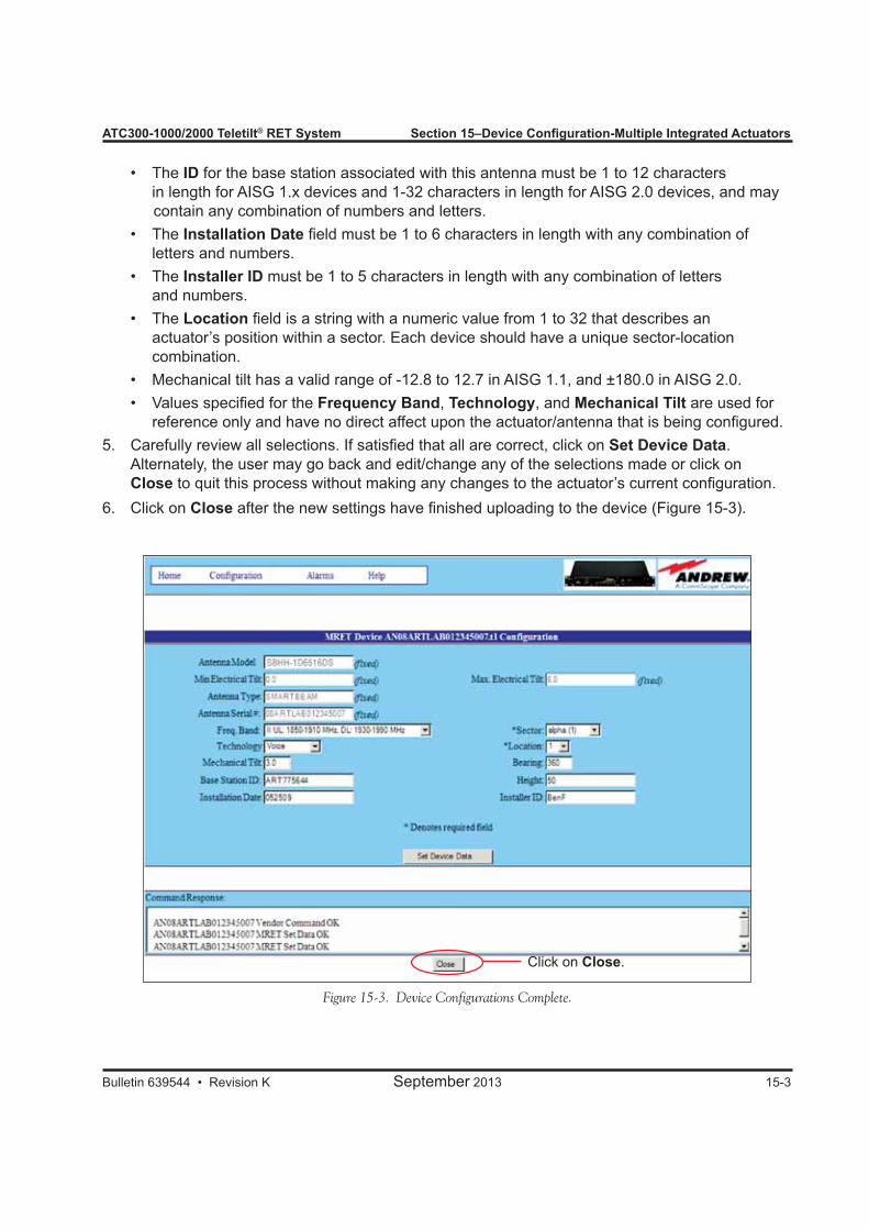
ATC300-1000/2000 Teletilt® RET System Section 15–Device Configuration-Multiple Integrated Actuators
Bulletin 639544 • Revision K September 2013 15-3
• The ID for the base station associated with this antenna must be 1 to 12 characters in length for AISG 1.x devices and 1-32 characters in length for AISG 2.0 devices, and may contain any combination of numbers and letters.
• The Installation Date field must be 1 to 6 characters in length with any combination of letters and numbers.
• The Installer ID must be 1 to 5 characters in length with any combination of letters and numbers.
• The Location field is a string with a numeric value from 1 to 32 that describes an actuator’s position within a sector. Each device should have a unique sector-location combination.
• Mechanical tilt has a valid range of -12.8 to 12.7 in AISG 1.1, and ±180.0 in AISG 2.0. • Values specified for the Frequency Band, Technology, and Mechanical Tilt are used for
reference only and have no direct affect upon the actuator/antenna that is being configured.5. Carefully review all selections. If satisfied that all are correct, click on Set Device Data.
Alternately, the user may go back and edit/change any of the selections made or click on Close to quit this process without making any changes to the actuator’s current configuration.
6. Click on Close after the new settings have finished uploading to the device (Figure 15-3).
Figure 15-3. Device Configurations Complete.
Click on Close.
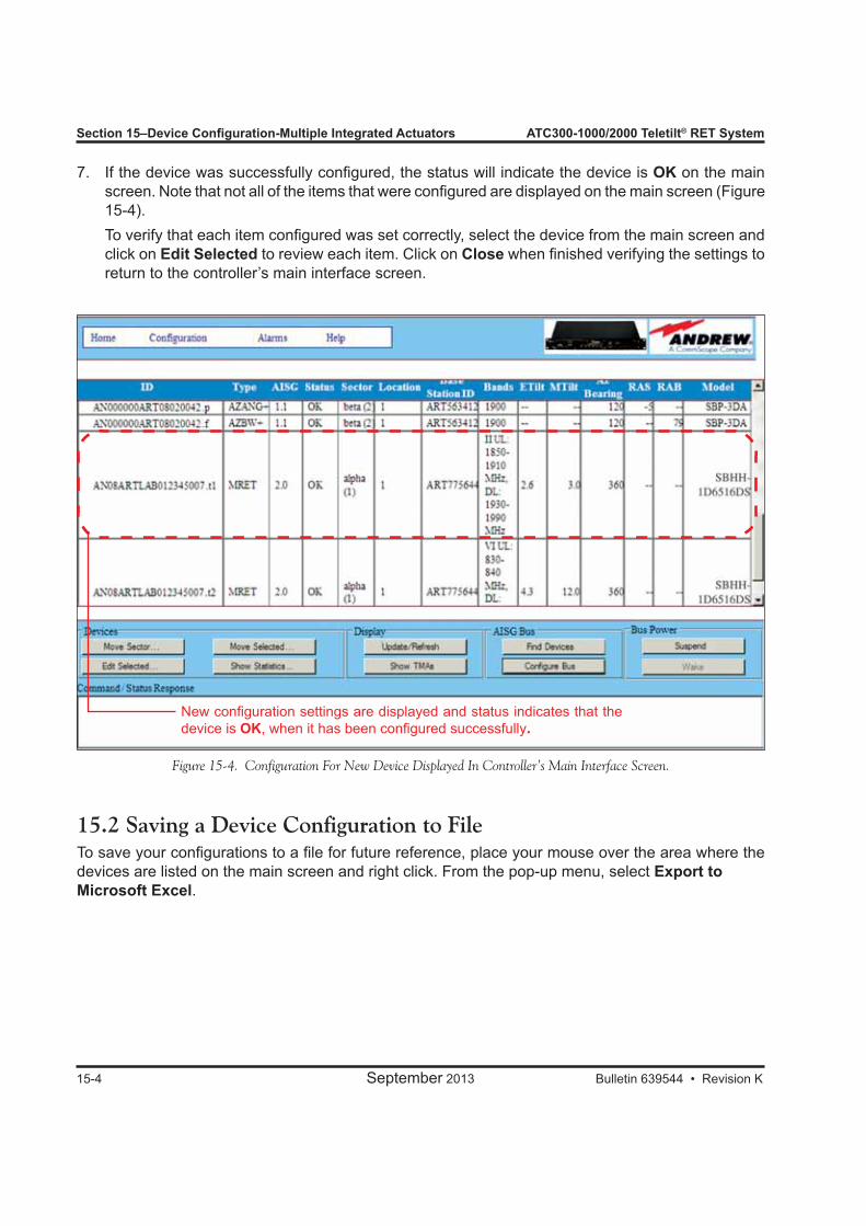
Section 15–Device Configuration-Multiple Integrated Actuators ATC300-1000/2000 Teletilt® RET System
15-4 September 2013 Bulletin 639544 • Revision K
7. If the device was successfully configured, the status will indicate the device is OK on the main screen. Note that not all of the items that were configured are displayed on the main screen (Figure 15-4).
To verify that each item configured was set correctly, select the device from the main screen and click on Edit Selected to review each item. Click on Close when finished verifying the settings to return to the controller’s main interface screen.
Figure 15-4. Configuration For New Device Displayed In Controller’s Main Interface Screen.
New configuration settings are displayed and status indicates that the device is OK, when it has been configured successfully.
15.2 Saving a Device Configuration to FileTo save your configurations to a file for future reference, place your mouse over the area where the devices are listed on the main screen and right click. From the pop-up menu, select Export to Microsoft Excel.
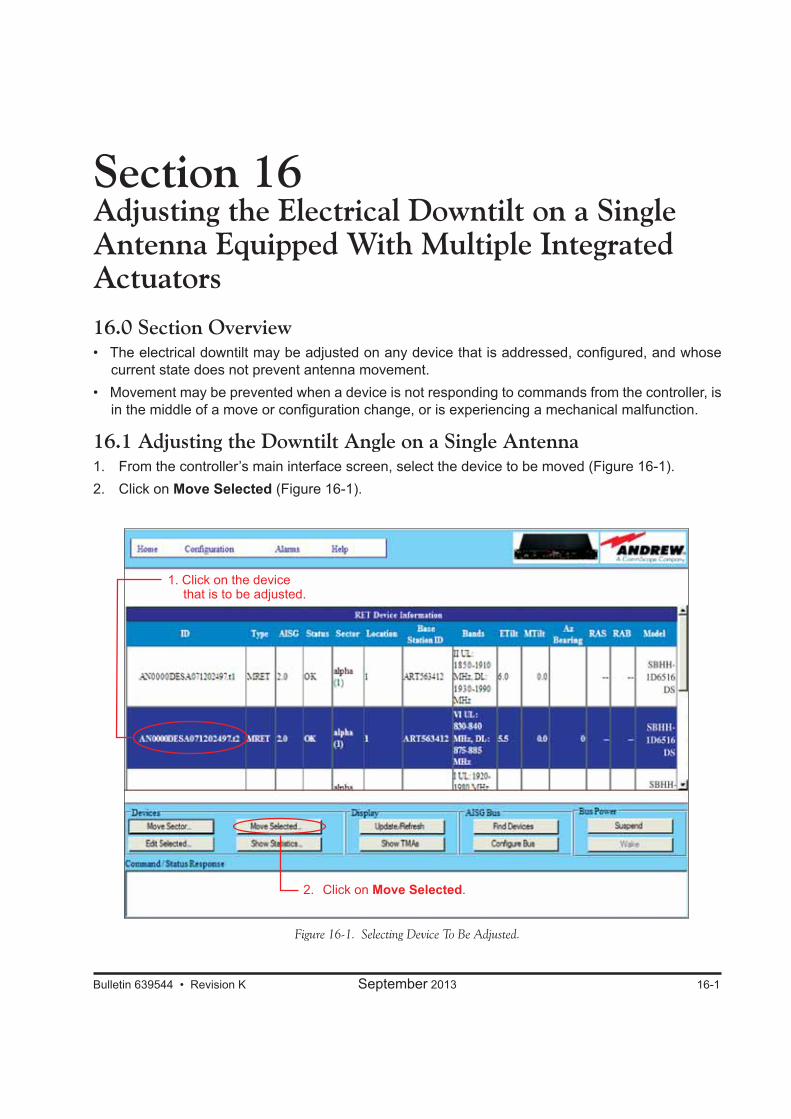
Bulletin 639544 • Revision K September 2013 16-1
Section 16Adjusting the Electrical Downtilt on a Single Antenna Equipped With Multiple Integrated Actuators16.0 Section Overview• The electrical downtilt may be adjusted on any device that is addressed, configured, and whose
current state does not prevent antenna movement. • Movement may be prevented when a device is not responding to commands from the controller, is
in the middle of a move or configuration change, or is experiencing a mechanical malfunction.
16.1 Adjusting the Downtilt Angle on a Single Antenna1. From the controller’s main interface screen, select the device to be moved (Figure 16-1).2. Click on Move Selected (Figure 16-1).
Figure 16-1. Selecting Device To Be Adjusted.
1. Click on the device that is to be adjusted.
2. Click on Move Selected.
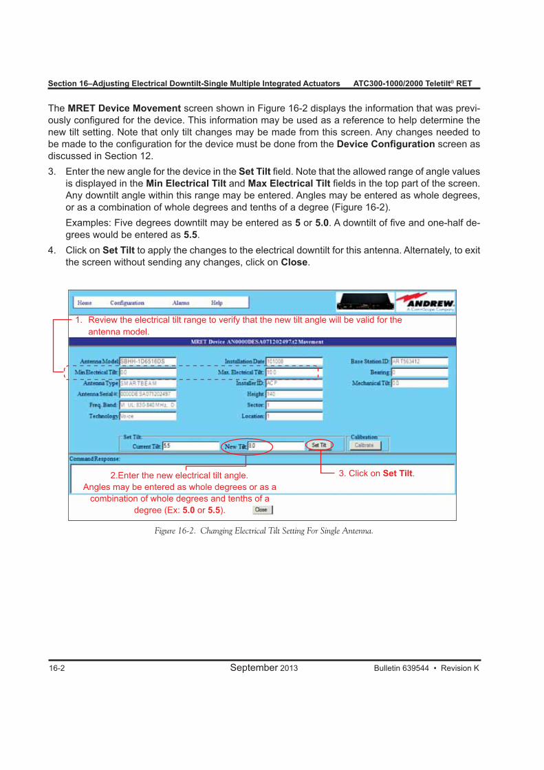
16-2 September 2013 Bulletin 639544 • Revision K
Section 16–Adjusting Electrical Downtilt-Single Multiple Integrated Actuators ATC300-1000/2000 Teletilt® RET
The MRET Device Movement screen shown in Figure 16-2 displays the information that was previ-ously configured for the device. This information may be used as a reference to help determine the new tilt setting. Note that only tilt changes may be made from this screen. Any changes needed to be made to the configuration for the device must be done from the Device Configuration screen as discussed in Section 12.3. Enter the new angle for the device in the Set Tilt field. Note that the allowed range of angle values
is displayed in the Min Electrical Tilt and Max Electrical Tilt fields in the top part of the screen. Any downtilt angle within this range may be entered. Angles may be entered as whole degrees, or as a combination of whole degrees and tenths of a degree (Figure 16-2).
Examples: Five degrees downtilt may be entered as 5 or 5.0. A downtilt of five and one-half de-grees would be entered as 5.5.
4. Click on Set Tilt to apply the changes to the electrical downtilt for this antenna. Alternately, to exit the screen without sending any changes, click on Close.
Figure 16-2. Changing Electrical Tilt Setting For Single Antenna.
1. Review the electrical tilt range to verify that the new tilt angle will be valid for the antenna model.
2.Enter the new electrical tilt angle. Angles may be entered as whole degrees or as a
combination of whole degrees and tenths of a degree (Ex: 5.0 or 5.5).
3. Click on Set Tilt.
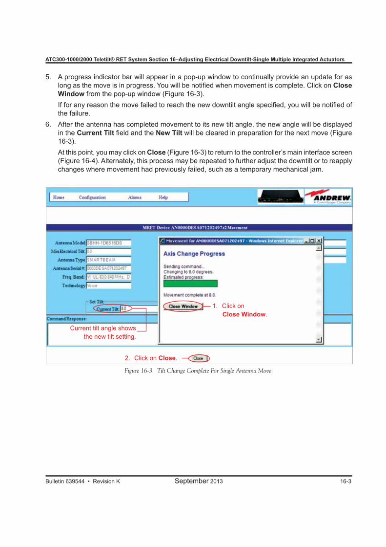
Bulletin 639544 • Revision K September 2013 16-3
ATC300-1000/2000 Teletilt® RET System Section 16–Adjusting Electrical Downtilt-Single Multiple Integrated Actuators
5. A progress indicator bar will appear in a pop-up window to continually provide an update for as long as the move is in progress. You will be notified when movement is complete. Click on Close Window from the pop-up window (Figure 16-3).
If for any reason the move failed to reach the new downtilt angle specified, you will be notified of the failure.
6. After the antenna has completed movement to its new tilt angle, the new angle will be displayed in the Current Tilt field and the New Tilt will be cleared in preparation for the next move (Figure 16-3).
At this point, you may click on Close (Figure 16-3) to return to the controller’s main interface screen (Figure 16-4). Alternately, this process may be repeated to further adjust the downtilt or to reapply changes where movement had previously failed, such as a temporary mechanical jam.
Figure 16-3. Tilt Change Complete For Single Antenna Move.
1. Click on Close Window.
2. Click on Close.
Current tilt angle shows the new tilt setting.
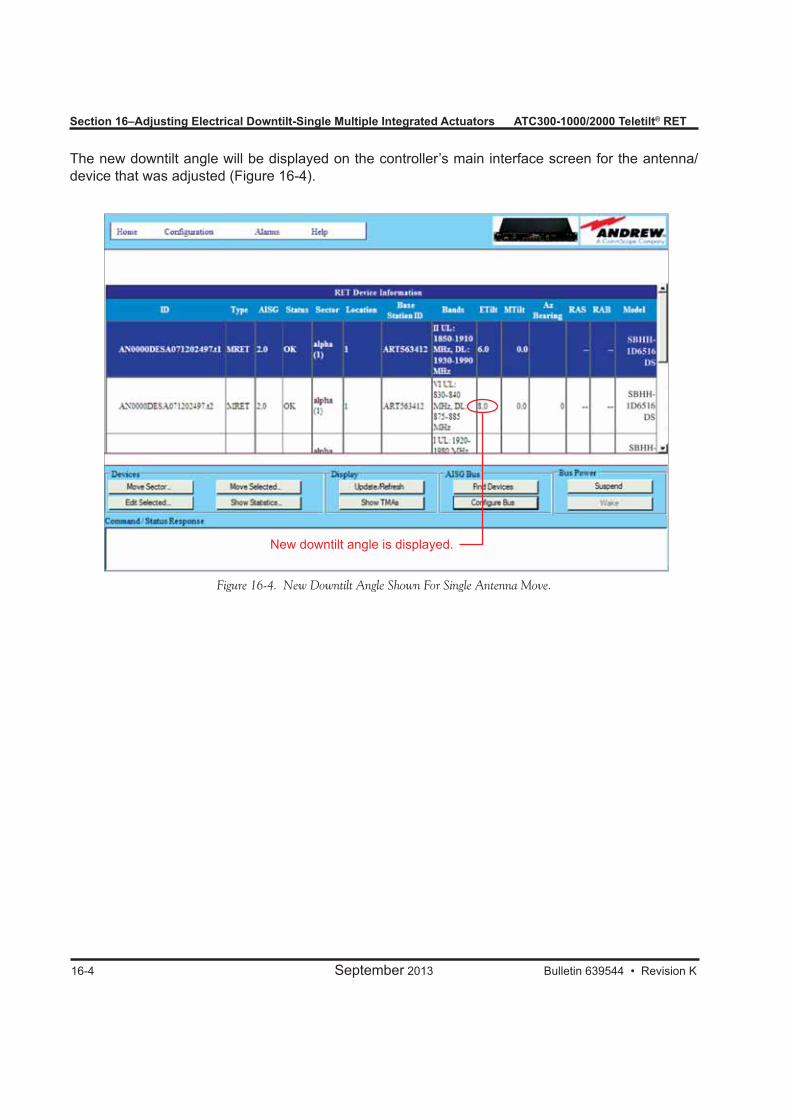
16-4 September 2013 Bulletin 639544 • Revision K
Section 16–Adjusting Electrical Downtilt-Single Multiple Integrated Actuators ATC300-1000/2000 Teletilt® RET
Figure 16-4. New Downtilt Angle Shown For Single Antenna Move.
New downtilt angle is displayed.
The new downtilt angle will be displayed on the controller’s main interface screen for the antenna/device that was adjusted (Figure 16-4).

Bulletin 639544 • Revision K September 2013 17-1
Section 17Adjusting the Electrical Downtilt on a Group of Antennas Equipped with Multiple Integrated Actuators
17.0 Section OverviewIn addition to changing the downtilt of a single antenna, changes may also be applied to a group of antennas. The antennas that can be included in a group move must be in the same sector and have the same electrical tilt range (same minimum and maximum tilt).
17.1 Adjusting the Downtilt Angle on a Group of Antennas1. Select a device from the controller’s main interface screen that is to be included in the sector move
(Figure 17-1). 2. Click on Move Sector (Figure 17-1).
Figure 17-1. Selecting A Device That Is To Be Included In The Sector Move.
1. Click on a device that is to be included in the sector move.
2. Click on Move Sector.
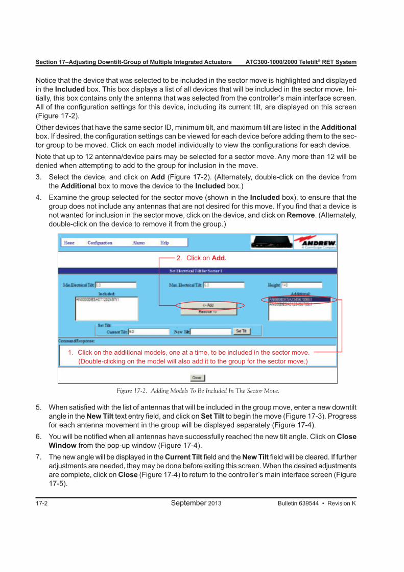
Section 17–Adjusting Downtilt-Group of Multiple Integrated Actuators ATC300-1000/2000 Teletilt® RET System
17-2 September 2013 Bulletin 639544 • Revision K
Notice that the device that was selected to be included in the sector move is highlighted and displayed in the Included box. This box displays a list of all devices that will be included in the sector move. Ini-tially, this box contains only the antenna that was selected from the controller’s main interface screen. All of the configuration settings for this device, including its current tilt, are displayed on this screen (Figure 17-2).Other devices that have the same sector ID, minimum tilt, and maximum tilt are listed in the Additional box. If desired, the configuration settings can be viewed for each device before adding them to the sec-tor group to be moved. Click on each model individually to view the configurations for each device.Note that up to 12 antenna/device pairs may be selected for a sector move. Any more than 12 will be denied when attempting to add to the group for inclusion in the move.3. Select the device, and click on Add (Figure 17-2). (Alternately, double-click on the device from
the Additional box to move the device to the Included box.)4. Examine the group selected for the sector move (shown in the Included box), to ensure that the
group does not include any antennas that are not desired for this move. If you find that a device is not wanted for inclusion in the sector move, click on the device, and click on Remove. (Alternately, double-click on the device to remove it from the group.)
5. When satisfied with the list of antennas that will be included in the group move, enter a new downtilt angle in the New Tilt text entry field, and click on Set Tilt to begin the move (Figure 17-3). Progress for each antenna movement in the group will be displayed separately (Figure 17-4).
6. You will be notified when all antennas have successfully reached the new tilt angle. Click on Close Window from the pop-up window (Figure 17-4).
7. The new angle will be displayed in the Current Tilt field and the New Tilt field will be cleared. If further adjustments are needed, they may be done before exiting this screen. When the desired adjustments are complete, click on Close (Figure 17-4) to return to the controller’s main interface screen (Figure 17-5).
2. Click on Add.
1. Click on the additional models, one at a time, to be included in the sector move. (Double-clicking on the model will also add it to the group for the sector move.)
Figure 17-2. Adding Models To Be Included In The Sector Move.
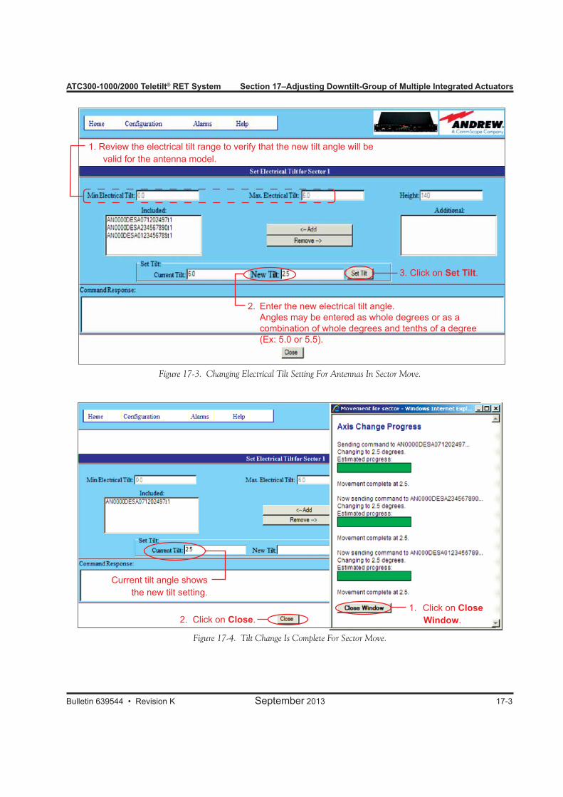
ATC300-1000/2000 Teletilt® RET System Section 17–Adjusting Downtilt-Group of Multiple Integrated Actuators
Bulletin 639544 • Revision K September 2013 17-3
2. Click on Close.1. Click on Close
Window.
Current tilt angle shows the new tilt setting.
Figure 17-3. Changing Electrical Tilt Setting For Antennas In Sector Move.
Figure 17-4. Tilt Change Is Complete For Sector Move.
2. Enter the new electrical tilt angle. Angles may be entered as whole degrees or as a
combination of whole degrees and tenths of a degree (Ex: 5.0 or 5.5).
1. Review the electrical tilt range to verify that the new tilt angle will be valid for the antenna model.
3. Click on Set Tilt.
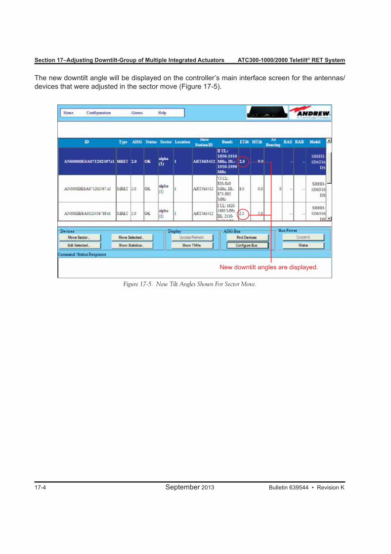
Section 17–Adjusting Downtilt-Group of Multiple Integrated Actuators ATC300-1000/2000 Teletilt® RET System
17-4 September 2013 Bulletin 639544 • Revision K
Figure 17-5. New Tilt Angles Shown For Sector Move.
The new downtilt angle will be displayed on the controller’s main interface screen for the antennas/devices that were adjusted in the sector move (Figure 17-5).
New downtilt angles are displayed.

Bulletin 639544 • Revision K September 2013
Part 7Operating Instructions for
SmartBeam® Antennas

Part 7–Operating Instructions for SmartBeam® Antennas
September 2013 Bulletin 639544 • Revision K
ATC300-1000/2000 Teletilt® RET System
This page intentionally left blank.
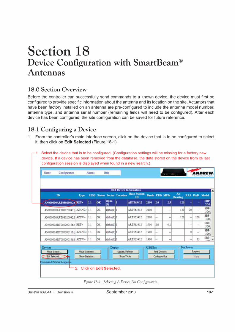
Bulletin 639544 • Revision K September 2013 18-1
Section 18Device Configuration with SmartBeam® Antennas
18.0 Section OverviewBefore the controller can successfully send commands to a known device, the device must first be configured to provide specific information about the antenna and its location on the site. Actuators that have been factory installed on an antenna are pre-configured to include the antenna model number, antenna type, and antenna serial number (remaining fields will need to be configured). After each device has been configured, the site configuration can be saved for future reference.
18.1 Configuring a Device1. From the controller’s main interface screen, click on the device that is to be configured to select
it; then click on Edit Selected (Figure 18-1).
Figure 18-1. Selecting A Device For Configuration.
2. Click on Edit Selected.
1. Select the device that is to be configured. (Configuration settings will be missing for a factory new device. If a device has been removed from the database, the data stored on the device from its last configuration session is displayed when found in a new search.)
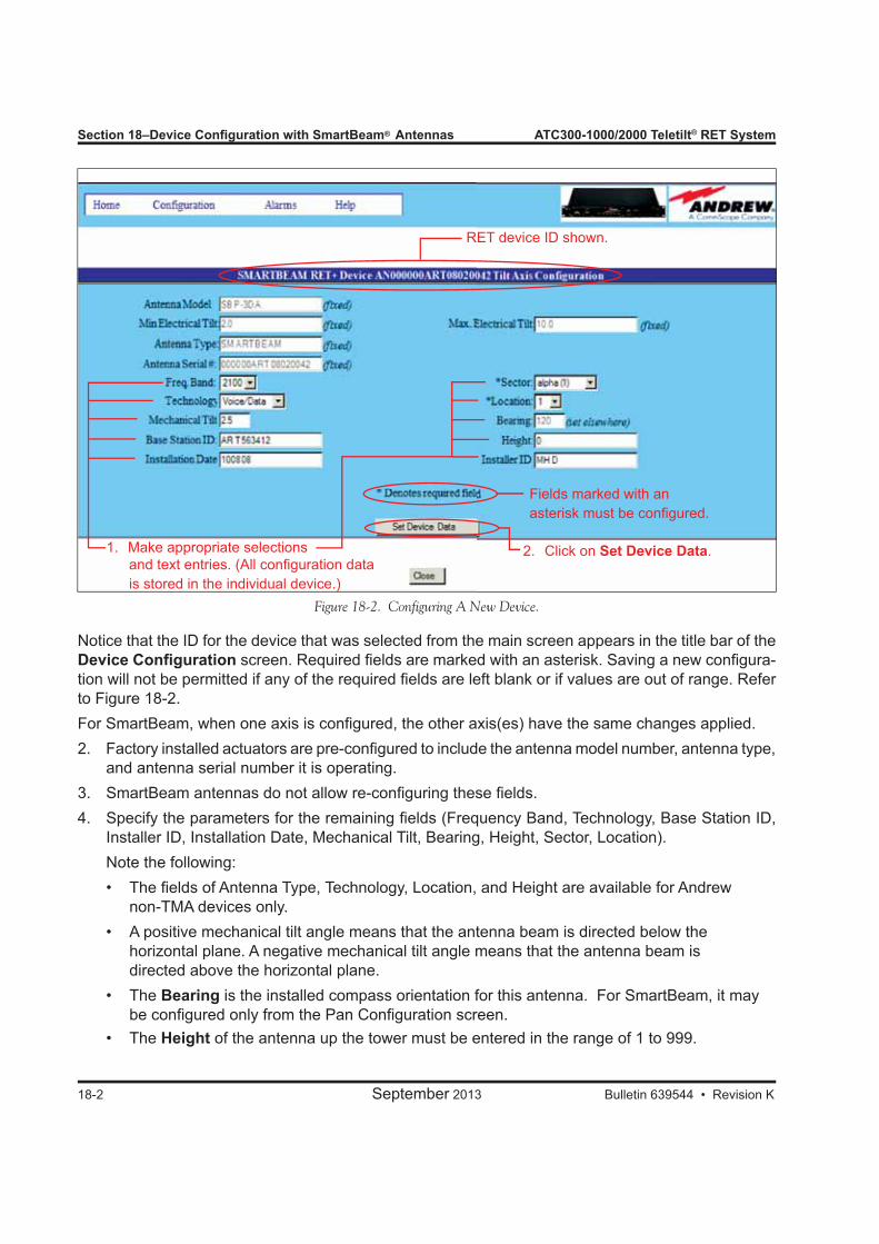
Section 18–Device Configuration with SmartBeam® Antennas ATC300-1000/2000 Teletilt® RET System
18-2 September 2013 Bulletin 639544 • Revision K
Notice that the ID for the device that was selected from the main screen appears in the title bar of the Device Configuration screen. Required fields are marked with an asterisk. Saving a new configura-tion will not be permitted if any of the required fields are left blank or if values are out of range. Refer to Figure 18-2.For SmartBeam, when one axis is configured, the other axis(es) have the same changes applied.2. Factory installed actuators are pre-configured to include the antenna model number, antenna type,
and antenna serial number it is operating.3. SmartBeam antennas do not allow re-configuring these fields.4. Specify the parameters for the remaining fields (Frequency Band, Technology, Base Station ID,
Installer ID, Installation Date, Mechanical Tilt, Bearing, Height, Sector, Location). Note the following:• The fields of Antenna Type, Technology, Location, and Height are available for Andrew non-TMA devices only.• A positive mechanical tilt angle means that the antenna beam is directed below the horizontal plane. A negative mechanical tilt angle means that the antenna beam is directed above the horizontal plane. • The Bearing is the installed compass orientation for this antenna. For SmartBeam, it may be configured only from the Pan Configuration screen.• The Height of the antenna up the tower must be entered in the range of 1 to 999.
Figure 18-2. Configuring A New Device.
Fields marked with an asterisk must be configured.
2. Click on Set Device Data.1. Make appropriate selections and text entries. (All configuration data is stored in the individual device.)
RET device ID shown.
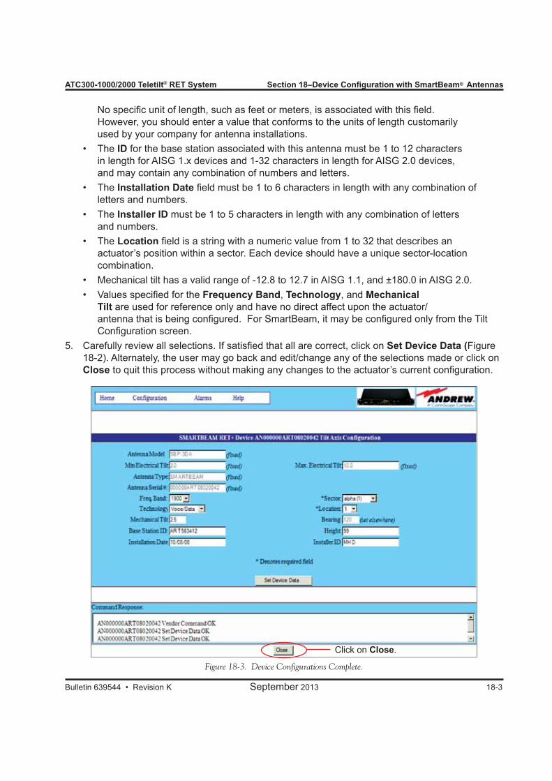
ATC300-1000/2000 Teletilt® RET System Section 18–Device Configuration with SmartBeam® Antennas
Bulletin 639544 • Revision K September 2013 18-3
No specific unit of length, such as feet or meters, is associated with this field. However, you should enter a value that conforms to the units of length customarily used by your company for antenna installations.
• The ID for the base station associated with this antenna must be 1 to 12 characters in length for AISG 1.x devices and 1-32 characters in length for AISG 2.0 devices, and may contain any combination of numbers and letters.
• The Installation Date field must be 1 to 6 characters in length with any combination of letters and numbers.
• The Installer ID must be 1 to 5 characters in length with any combination of letters and numbers.
• The Location field is a string with a numeric value from 1 to 32 that describes an actuator’s position within a sector. Each device should have a unique sector-location combination.
• Mechanical tilt has a valid range of -12.8 to 12.7 in AISG 1.1, and ±180.0 in AISG 2.0. • Values specified for the Frequency Band, Technology, and Mechanical
Tilt are used for reference only and have no direct affect upon the actuator/ antenna that is being configured. For SmartBeam, it may be configured only from the Tilt Configuration screen.
5. Carefully review all selections. If satisfied that all are correct, click on Set Device Data (Figure 18-2). Alternately, the user may go back and edit/change any of the selections made or click on Close to quit this process without making any changes to the actuator’s current configuration.
Figure 18-3. Device Configurations Complete.
Click on Close.
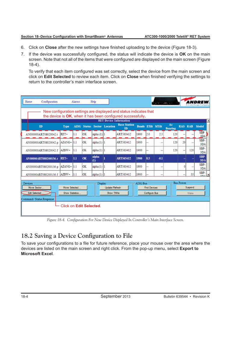
Section 18–Device Configuration with SmartBeam® Antennas ATC300-1000/2000 Teletilt® RET System
18-4 September 2013 Bulletin 639544 • Revision K
6. Click on Close after the new settings have finished uploading to the device (Figure 18-3).7. If the device was successfully configured, the status will indicate the device is OK on the main
screen. Note that not all of the items that were configured are displayed on the main screen (Figure 18-4).
To verify that each item configured was set correctly, select the device from the main screen and click on Edit Selected to review each item. Click on Close when finished verifying the settings to return to the controller’s main interface screen.
Figure 18-4. Configuration For New Device Displayed In Controller’s Main Interface Screen.
18.2 Saving a Device Configuration to FileTo save your configurations to a file for future reference, place your mouse over the area where the devices are listed on the main screen and right click. From the pop-up menu, select Export to Microsoft Excel.
Click on Edit Selected.
New configuration settings are displayed and status indicates that the device is OK, when it has been configured successfully.

Bulletin 639544 • Revision K September 2013 19-1
Section 19Adjusting the Electrical Downtilt on a Single SmartBeam® Antenna19.0 Section Overview• The electrical downtilt may be adjusted on a tilt axis of a SmartBeam antenna that is addressed,
configured, and whose current state does not prevent antenna movement. • Movement may be prevented when a device is not responding to commands from the controller, is
in the middle of a move or configuration change, or is experiencing a mechanical malfunction.
19.1 Adjusting the Downtilt Angle on a Single Antenna1. From the controller’s main interface screen, select the device ending in a “.t” (for “tilt”) to be moved
(Figure 19-1).2. Click on Move Selected (Figure 19-1).
Figure 19-1. Selecting Device To Be Adjusted.
1. Click on the device that is to be adjusted.
2. Click on Move Selected.
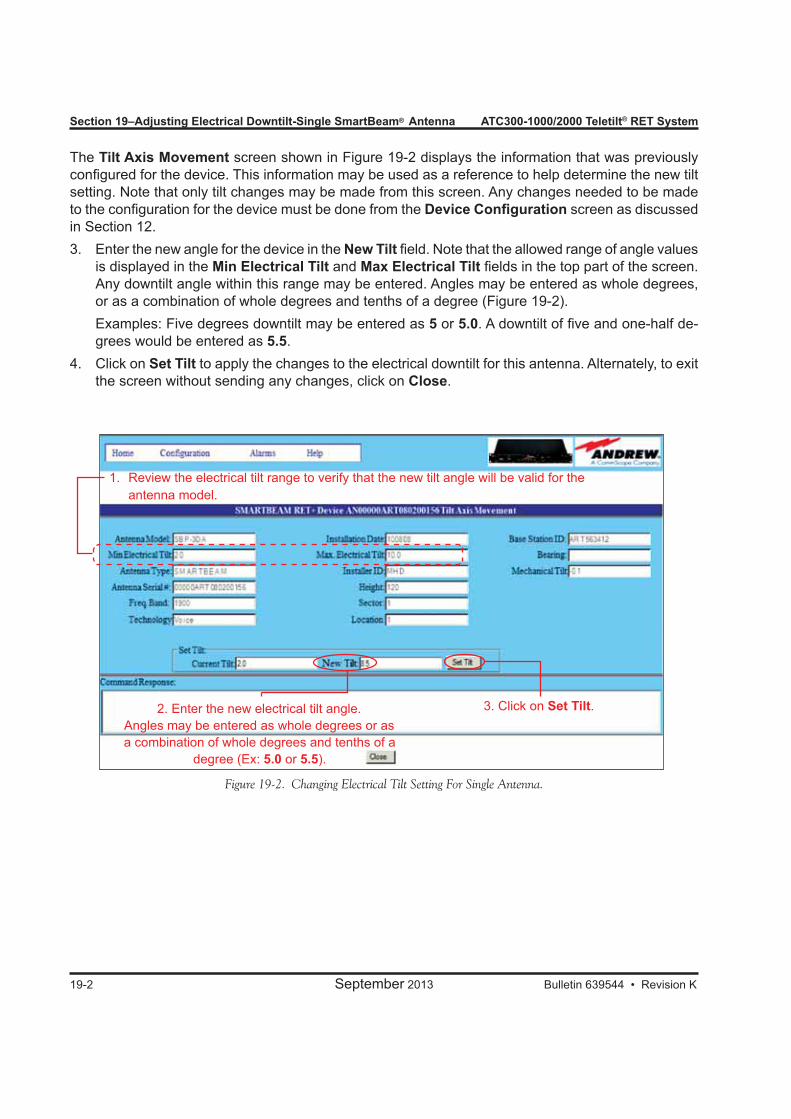
Section 19–Adjusting Electrical Downtilt-Single SmartBeam® Antenna ATC300-1000/2000 Teletilt® RET System
19-2 September 2013 Bulletin 639544 • Revision K
The Tilt Axis Movement screen shown in Figure 19-2 displays the information that was previously configured for the device. This information may be used as a reference to help determine the new tilt setting. Note that only tilt changes may be made from this screen. Any changes needed to be made to the configuration for the device must be done from the Device Configuration screen as discussed in Section 12.3. Enter the new angle for the device in the New Tilt field. Note that the allowed range of angle values
is displayed in the Min Electrical Tilt and Max Electrical Tilt fields in the top part of the screen. Any downtilt angle within this range may be entered. Angles may be entered as whole degrees, or as a combination of whole degrees and tenths of a degree (Figure 19-2).
Examples: Five degrees downtilt may be entered as 5 or 5.0. A downtilt of five and one-half de-grees would be entered as 5.5.
4. Click on Set Tilt to apply the changes to the electrical downtilt for this antenna. Alternately, to exit the screen without sending any changes, click on Close.
Figure 19-2. Changing Electrical Tilt Setting For Single Antenna.
1. Review the electrical tilt range to verify that the new tilt angle will be valid for the antenna model.
2. Enter the new electrical tilt angle.Angles may be entered as whole degrees or as a combination of whole degrees and tenths of a
degree (Ex: 5.0 or 5.5).
3. Click on Set Tilt.

ATC300-1000/2000 Teletilt® RET System Section 19–Adjusting Electrical Downtilt-Single SmartBeam® Antenna
Bulletin 639544 • Revision K September 2013 19-3
5. A progress indicator bar will appear in a pop-up window to continually provide an update for as long as the move is in progress. You will be notified when movement is complete. Click on Close Window from the pop-up window (Figure 19-3).
If for any reason the move failed to reach the new downtilt angle specified, you will be notified of the failure.
6. After the antenna has completed movement to its new tilt angle, the new angle will be displayed in the Current Tilt field and the New Tilt will be cleared in preparation for the next move (Figure 19-3).
At this point, you may click on Close (Figure 19-3) to return to the controller’s main interface screen (Figure 19-4). Alternately, this process may be repeated to further adjust the downtilt or to reapply changes where movement had previously failed, such as a temporary mechanical jam.
Figure 19-3. Tilt Change Complete For Single Antenna Move.
2. Click on Close.
Current tilt angle shows the new tilt setting. 1. Click on
Close Window.
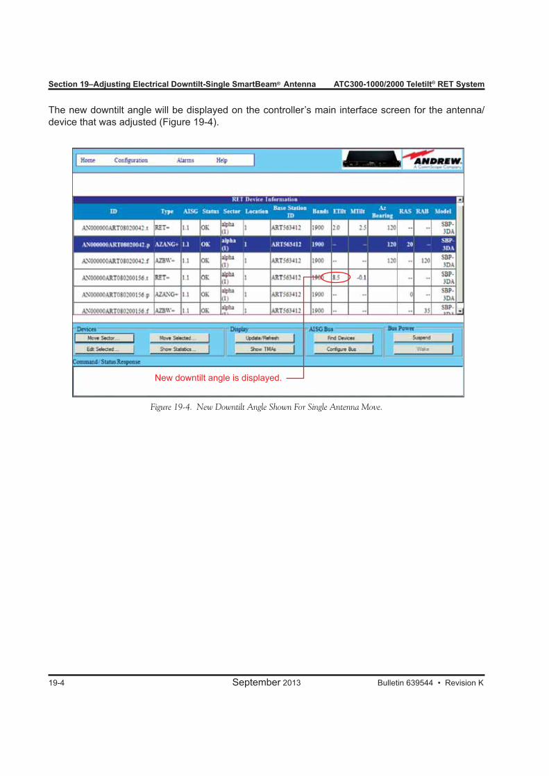
Section 19–Adjusting Electrical Downtilt-Single SmartBeam® Antenna ATC300-1000/2000 Teletilt® RET System
19-4 September 2013 Bulletin 639544 • Revision K
Figure 19-4. New Downtilt Angle Shown For Single Antenna Move.
New downtilt angle is displayed.
The new downtilt angle will be displayed on the controller’s main interface screen for the antenna/device that was adjusted (Figure 19-4).

Bulletin 639544 • Revision K September 2013 20-1
Section 20Adjusting the Pan on a Single SmartBeam® Antenna
20.0 Section Overview• The azimuth offset may be adjusted on a pan axis of a SmartBeam antenna that is addressed,
configured, and whose current state does not prevent antenna movement. • Movement may be prevented when a device is not responding to commands from the controller, is
in the middle of a move or configuration change, or is experiencing a mechanical malfunction.
20.1 Adjusting the Pan on a Single Antenna1. From the controller’s main interface screen, select the device ending in a “.p” (for “pan”) to be
moved (Figure 20-1).2. Click on Move Selected (Figure 20-1).
Figure 20-1. Selecting Device To Be Adjusted.
1. Click on the device that is to be adjusted.
2. Click on Move Selected.
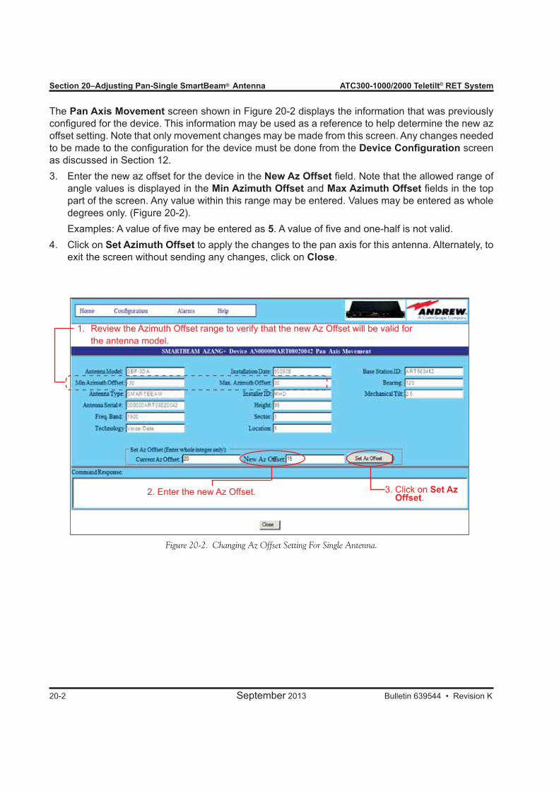
Section 20–Adjusting Pan-Single SmartBeam® Antenna ATC300-1000/2000 Teletilt® RET System
20-2 September 2013 Bulletin 639544 • Revision K
The Pan Axis Movement screen shown in Figure 20-2 displays the information that was previously configured for the device. This information may be used as a reference to help determine the new az offset setting. Note that only movement changes may be made from this screen. Any changes needed to be made to the configuration for the device must be done from the Device Configuration screen as discussed in Section 12.3. Enter the new az offset for the device in the New Az Offset field. Note that the allowed range of
angle values is displayed in the Min Azimuth Offset and Max Azimuth Offset fields in the top part of the screen. Any value within this range may be entered. Values may be entered as whole degrees only. (Figure 20-2).
Examples: A value of five may be entered as 5. A value of five and one-half is not valid. 4. Click on Set Azimuth Offset to apply the changes to the pan axis for this antenna. Alternately, to
exit the screen without sending any changes, click on Close.
Figure 20-2. Changing Az Offset Setting For Single Antenna.
1. Review the Azimuth Offset range to verify that the new Az Offset will be valid for the antenna model.
2. Enter the new Az Offset. 3. Click on Set Az Offset.
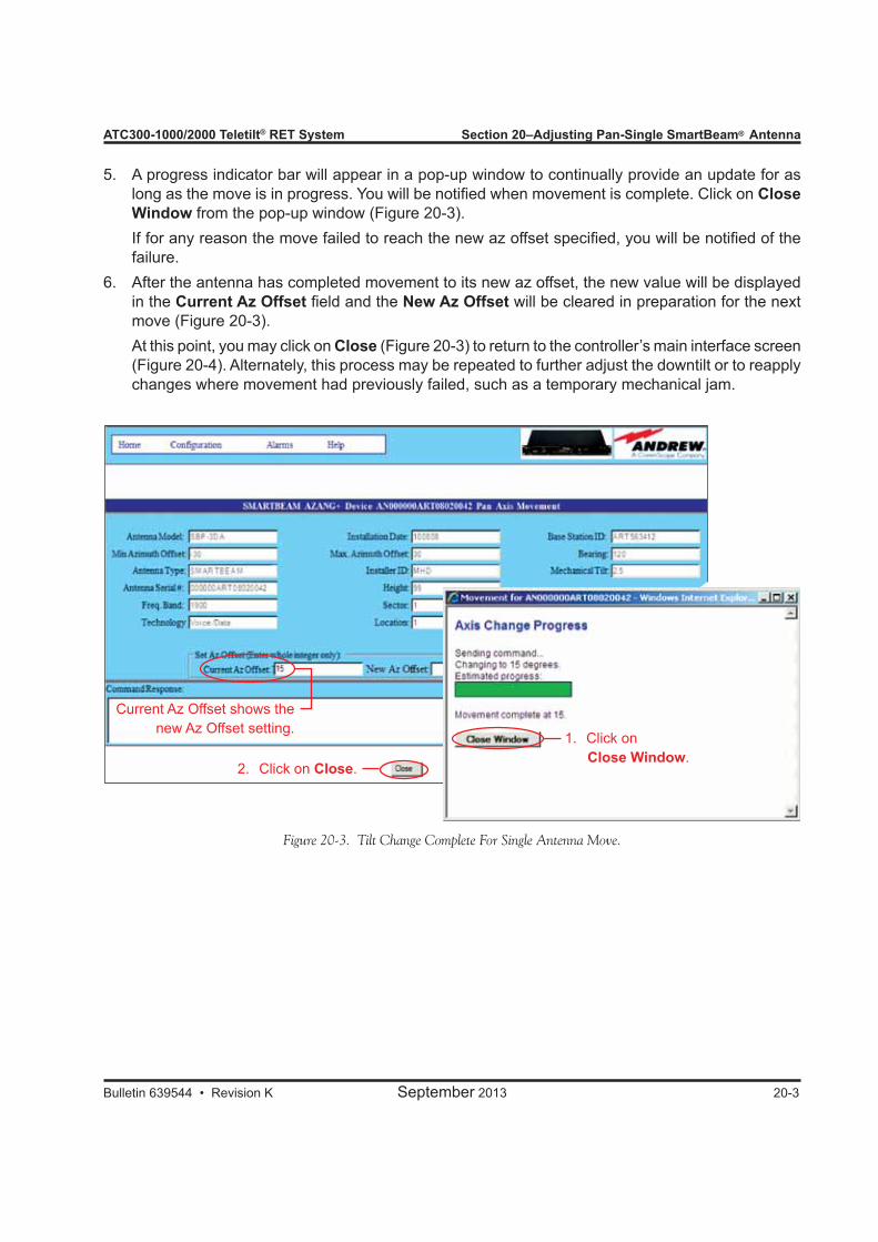
ATC300-1000/2000 Teletilt® RET System Section 20–Adjusting Pan-Single SmartBeam® Antenna
Bulletin 639544 • Revision K September 2013 20-3
5. A progress indicator bar will appear in a pop-up window to continually provide an update for as long as the move is in progress. You will be notified when movement is complete. Click on Close Window from the pop-up window (Figure 20-3).
If for any reason the move failed to reach the new az offset specified, you will be notified of the failure.
6. After the antenna has completed movement to its new az offset, the new value will be displayed in the Current Az Offset field and the New Az Offset will be cleared in preparation for the next move (Figure 20-3).
At this point, you may click on Close (Figure 20-3) to return to the controller’s main interface screen (Figure 20-4). Alternately, this process may be repeated to further adjust the downtilt or to reapply changes where movement had previously failed, such as a temporary mechanical jam.
Figure 20-3. Tilt Change Complete For Single Antenna Move.
2. Click on Close.
Current Az Offset shows the new Az Offset setting.
1. Click on Close Window.
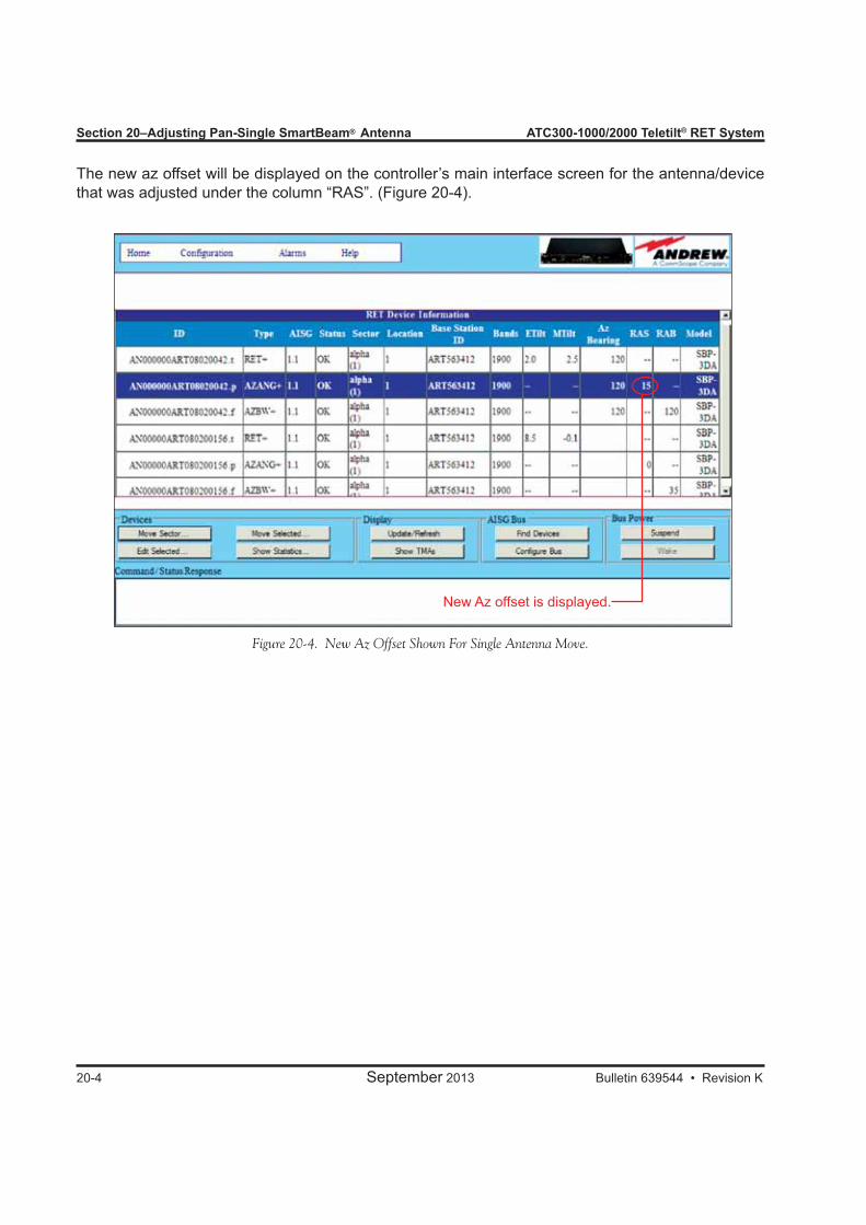
Section 20–Adjusting Pan-Single SmartBeam® Antenna ATC300-1000/2000 Teletilt® RET System
20-4 September 2013 Bulletin 639544 • Revision K
Figure 20-4. New Az Offset Shown For Single Antenna Move.
New Az offset is displayed.
The new az offset will be displayed on the controller’s main interface screen for the antenna/device that was adjusted under the column “RAS”. (Figure 20-4).
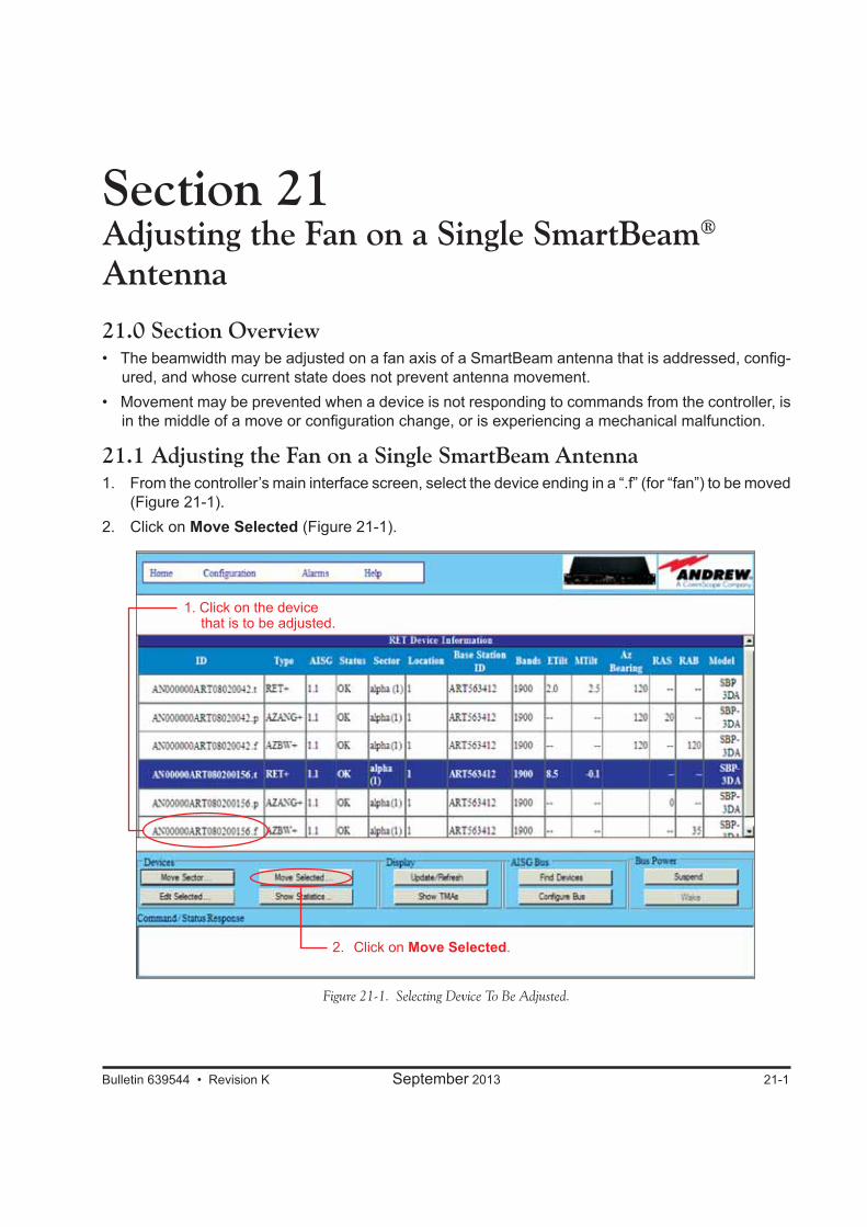
Bulletin 639544 • Revision K September 2013 21-1
Section 21Adjusting the Fan on a Single SmartBeam® Antenna
21.0 Section Overview• The beamwidth may be adjusted on a fan axis of a SmartBeam antenna that is addressed, config-
ured, and whose current state does not prevent antenna movement. • Movement may be prevented when a device is not responding to commands from the controller, is
in the middle of a move or configuration change, or is experiencing a mechanical malfunction.
21.1 Adjusting the Fan on a Single SmartBeam Antenna1. From the controller’s main interface screen, select the device ending in a “.f” (for “fan”) to be moved
(Figure 21-1).2. Click on Move Selected (Figure 21-1).
Figure 21-1. Selecting Device To Be Adjusted.
1. Click on the device that is to be adjusted.
2. Click on Move Selected.
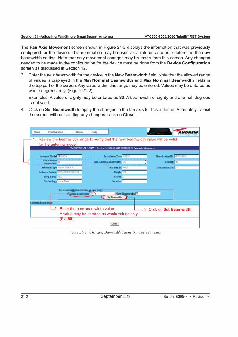
Section 21–Adjusting Fan-Single SmartBeam® Antenna ATC300-1000/2000 Teletilt® RET System
21-2 September 2013 Bulletin 639544 • Revision K
The Fan Axis Movement screen shown in Figure 21-2 displays the information that was previously configured for the device. This information may be used as a reference to help determine the new beamwidth setting. Note that only movement changes may be made from this screen. Any changes needed to be made to the configuration for the device must be done from the Device Configuration screen as discussed in Section 12.3. Enter the new beamwidth for the device in the New Beamwidth field. Note that the allowed range
of values is displayed in the Min Nominal Beamwidth and Max Nominal Beamwidth fields in the top part of the screen. Any value within this range may be entered. Values may be entered as whole degrees only. (Figure 21-2).
Examples: A value of eighty may be entered as 80. A beamwidth of eighty and one-half degrees is not valid.
4. Click on Set Beamwidth to apply the changes to the fan axis for this antenna. Alternately, to exit the screen without sending any changes, click on Close.
Figure 21-2. Changing Beamwidth Setting For Single Antenna.
1. Review the beamwidth range to verify that the new beamwidth value will be valid for the antenna model.
2. Enter the new beamwidth value. A value may be entered as whole values only (Ex: 80).
3. Click on Set Beamwidth.
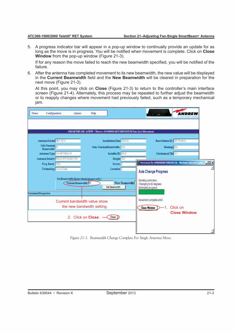
ATC300-1000/2000 Teletilt® RET System Section 21–Adjusting Fan-Single SmartBeam® Antenna
Bulletin 639544 • Revision K September 2013 21-3
5. A progress indicator bar will appear in a pop-up window to continually provide an update for as long as the move is in progress. You will be notified when movement is complete. Click on Close Window from the pop-up window (Figure 21-3).
If for any reason the move failed to reach the new beamwidth specified, you will be notified of the failure.
6. After the antenna has completed movement to its new beamwidth, the new value will be displayed in the Current Beamwidth field and the New Beamwidth will be cleared in preparation for the next move (Figure 21-3).
At this point, you may click on Close (Figure 21-3) to return to the controller’s main interface screen (Figure 21-4). Alternately, this process may be repeated to further adjust the beamwidth or to reapply changes where movement had previously failed, such as a temporary mechanical jam.
Figure 21-3. Beamwidth Change Complete For Single Antenna Move.
Current bandwidth value show the new bandwidth setting.
2. Click on Close.
1. Click on Close Window.
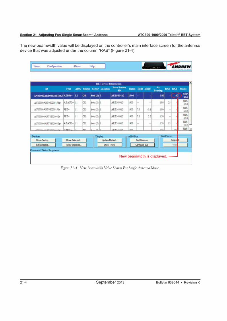
Section 21–Adjusting Fan-Single SmartBeam® Antenna ATC300-1000/2000 Teletilt® RET System
21-4 September 2013 Bulletin 639544 • Revision K
Figure 21-4. New Beamwidth Value Shown For Single Antenna Move.
New beamwidth is displayed.
The new beamwidth value will be displayed on the controller’s main interface screen for the antenna/device that was adjusted under the column “RAB” (Figure 21-4).

Bulletin 639544 • Revision K September 2013 22-1
Section 22Adjusting the Electrical Downtilt, Pan, or Fan on a Group of SmartBeam® Antennas
22.0 Section OverviewIn addition to changing the downtilt, az offset, and beamwidth of a single SmartBeam antenna, changes may also be applied to a group of antennas. The SmartBeam antennas that can be included in a group move must be in the same sector, have the same electrical tilt range (same minimum and maximum tilt), and be the same axis (tilt, pan, or fan).
22.1 Adjusting the Downtilt Angle, Az offset, or Beamwidth on a Group of SmartBeam Antennas1. Select a SmartBeam axis device from the controller’s main interface screen that is to be included
in the sector move (Figure 22-1). 2. Click on Move Sector (Figure 22-1).
Figure 22-1. Selecting A Device That Is To Be Included In The Sector Move.
1. Click on a device that is to be included in the sector move.
2. Click on Move Sector.

Section 22–Adjusting Electrical Downtilt, Pan, Fan-Group SmartBeam® Antennas ATC300-1000/2000 Teletilt® RET System
22-2 September 2013 Bulletin 639544 • Revision K
Figure 22-2. Adding Models To Be Included In The Sector Move.
Notice that the device that was selected to be included in the sector move is highlighted and displayed in the Included box. This box displays a list of all devices that will be included in the sector move. Ini-tially, this box contains only the antenna that was selected from the controller’s main interface screen. The minimum, maximum, and current tilt for this device is displayed on this screen (Figure 22-2).Other devices that have the same sector ID, minimum tilt, and maximum tilt, and are the same axis, are listed in the Additional box. If desired, the configuration settings can be viewed for each device before adding them to the sector group to be moved. Click on each model individually to view the configurations for each device.Note that up to 12 antenna/device pairs may be selected for a sector move. Any more than 12 will be denied when attempting to add to the group for inclusion in the move.3. Select the device, and click on Add (Figure 22-2). (Alternately, double-click on the device from
the Additional box to move the device to the Included box.)4. Examine the group selected for the sector move (shown in the Included box), to ensure that the
group does not include any antennas that are not desired for this move. If you find that a device is not wanted for inclusion in the sector move, click on the device, and click on Remove. (Alternately, double-click on the device to remove it from the group.)
5. When satisfied with the list of antennas that will be included in the group move, enter a new downtilt angle in the New Tilt text entry field, and click on Set Tilt to begin the move (Figure 22-3). Prog-ress for each antenna movement in the group will be displayed separately (Figure 22-4). (Note that these fields will have the appropriate labels for the axes selected.)
6. You will be notified when all antennas have successfully reached the new tilt angle. Click on Close Window from the pop-up window (Figure 22-4).
7. The new angle will be displayed in the Current Tilt field and the New Tilt field will be cleared. If further adjustments are needed, they may be done before exiting this screen. When the desired adjustments are complete, click on Close (Figure 22-4) to return to the controller’s main interface screen (Figure 22-5).
2. Click on Add.
1. Click on the additional models, one at a time, to be included in the sector move. (Double-clicking on the model will also add it to the group for the sector move.)
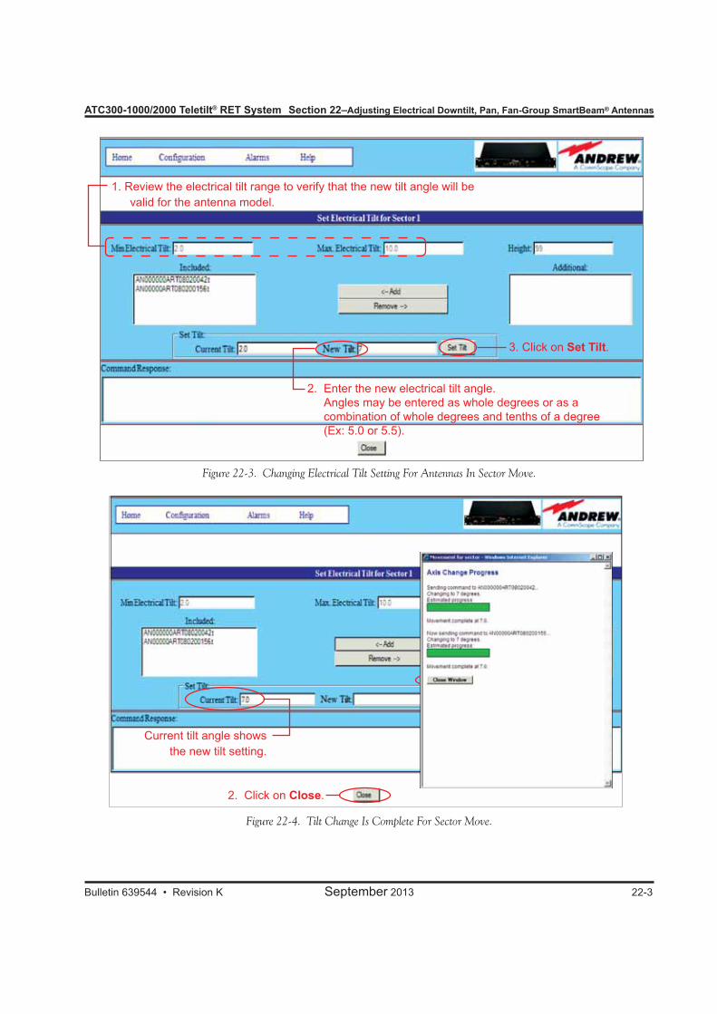
ATC300-1000/2000 Teletilt® RET System Section 22–Adjusting Electrical Downtilt, Pan, Fan-Group SmartBeam® Antennas
Bulletin 639544 • Revision K September 2013 22-3
2. Click on Close.
Current tilt angle shows the new tilt setting.
Figure 22-3. Changing Electrical Tilt Setting For Antennas In Sector Move.
Figure 22-4. Tilt Change Is Complete For Sector Move.
2. Enter the new electrical tilt angle. Angles may be entered as whole degrees or as a combination of whole degrees and tenths of a degree (Ex: 5.0 or 5.5).
1. Review the electrical tilt range to verify that the new tilt angle will be valid for the antenna model.
3. Click on Set Tilt.
1. Click on Close Window.
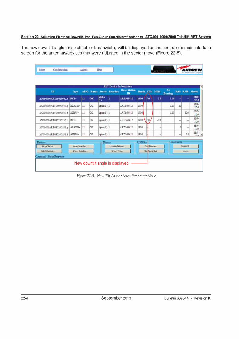
Section 22–Adjusting Electrical Downtilt, Pan, Fan-Group SmartBeam® Antennas ATC300-1000/2000 Teletilt® RET System
22-4 September 2013 Bulletin 639544 • Revision K
Figure 22-5. New Tilt Angle Shown For Sector Move.
New downtilt angle is displayed.
The new downtilt angle, or az offset, or beamwidth, will be displayed on the controller’s main interface screen for the antennas/devices that were adjusted in the sector move (Figure 22-5).
Bulletin 639544 • Revision K September 2013
Part 8Operating Instructions for Tower
Mounted Amplifiers

Part 8–Operating Instructions for Tower Mounted Amplifiers
September 2013 Bulletin 639544 • Revision K
ATC300-1000/2000 Teletilt® RET System
This page intentionally left blank.

Bulletin 639544 • Revision K September 2013 23-1
Section 23Tower Mounted Amplifier
23.0 Section OverviewAndrew tower mounted amplifiers (TMAs) are installed near the Tx/Rx antenna at the top of a cell tower. A base station antenna transmits a much stronger signal than what it receives back from the mobile phone, but the TMA corrects this imbalance. This uplink improvement with a stronger, clearer signal results in fewer dropped calls, improved call quality, and better coverage. The Andrew tower mounted amplifier extracts the AISG signal and dc power from the coaxial cable run and delivers it to the antenna RET line devices through its AISG interface.
23.1 AISG TMA (Tower Mounted Amplifier) Applications• An AISG TMA usually includes its own bias tee at the top of the system to get the dc voltage. If a TMA already uses a bias tee, a top Smart Bias Tee unit is not needed, nor can it be used. (The top Smart Bias Tee unit cannot pass dc power and data to the output RF port.)• A bottom Smart Bias Tee unit can be used to pass dc voltage and data to the coax line in applications where an AISG TMA has its own bias tee at the top of the system.• If a system includes both an AISG TMA and actuator(s), the TMA must have an AISG connector that can pass the dc power and data to the AISG jumper cable assembly.
23.2 Finding TMAsClick on 1. Find Devices from the controller’s main screen (Figure 23-1).Click on 2. Start Scan to activate the device search. Figure 23-2 shows a completed device scan.Click on 3. Home to return to ATC300 controller’s main screen (Figure 23-2).Any RET devices found are initially listed on the main screen. Click on the 4. Show TMAs button to see all TMAs found in the device scan. See Figure 23-3.
Figure 23-4 shows that one AISG TMA product is installed at the site.5.
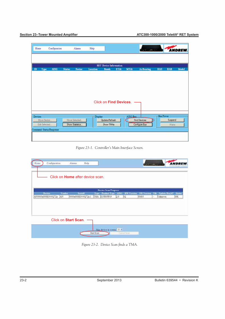
Section 23–Tower Mounted Amplifier ATC300-1000/2000 Teletilt® RET System
23-2 September 2013 Bulletin 639544 • Revision K
Figure 23-2. Device Scan finds a TMA.
Figure 23-1. Controller’s Main Interface Screen.
Click on Find Devices.
Click on Start Scan.
Click on Home after device scan.
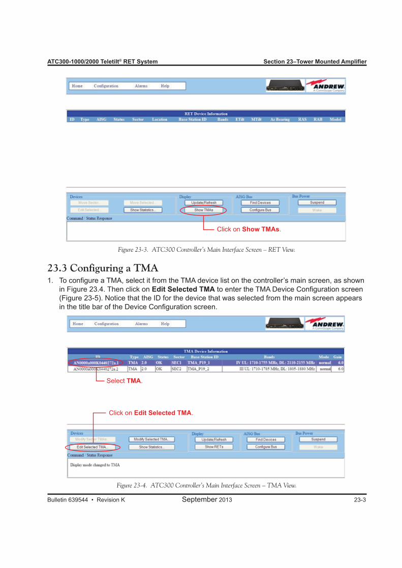
ATC300-1000/2000 Teletilt® RET System Section 23–Tower Mounted Amplifier
Bulletin 639544 • Revision K September 2013 23-3
Figure 23-3. ATC300 Controller’s Main Interface Screen – RET View.
23.3 Configuring a TMATo configure a TMA1. , select it from the TMA device list on the controller’s main screen, as shown in Figure 23.4. Then click on Edit Selected TMA to enter the TMA Device Configuration screen (Figure 23-5). Notice that the ID for the device that was selected from the main screen appears in the title bar of the Device Configuration screen.
Figure 23-4. ATC300 Controller’s Main Interface Screen – TMA View.
Select TMA.
Click on Edit Selected TMA.
Click on Show TMAs.
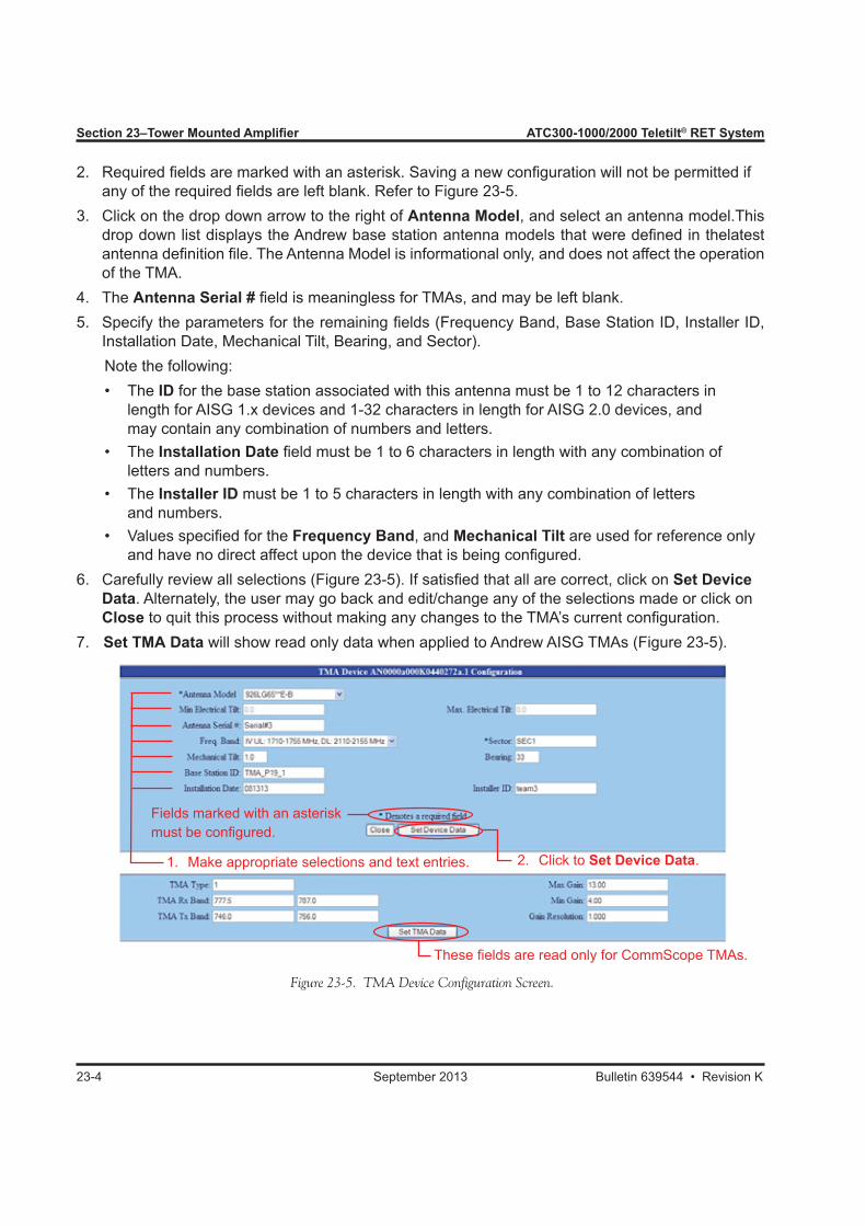
Section 23–Tower Mounted Amplifier ATC300-1000/2000 Teletilt® RET System
23-4 September 2013 Bulletin 639544 • Revision K
Required fields are marked with an asterisk. Saving a new configuration will not be permitted if 2. any of the required fields are left blank. Refer to Figure 23-5. Click on the drop down arrow to the right of 3. Antenna Model, and select an antenna model.This drop down list displays the Andrew base station antenna models that were defined in thelatest antenna definition file. The Antenna Model is informational only, and does not affect the operation of the TMA.The 4. Antenna Serial # field is meaningless for TMAs, and may be left blank.Specify the parameters for the remaining fields (Frequency Band, Base Station ID, Installer ID, 5. Installation Date, Mechanical Tilt, Bearing, and Sector).
Note the following: • The ID for the base station associated with this antenna must be 1 to 12 characters in length for AISG 1.x devices and 1-32 characters in length for AISG 2.0 devices, and may contain any combination of numbers and letters. • The Installation Date field must be 1 to 6 characters in length with any combination of letters and numbers. • The Installer ID must be 1 to 5 characters in length with any combination of letters and numbers. • Values specified for the Frequency Band, and Mechanical Tilt are used for reference only and have no direct affect upon the device that is being configured.
Carefully review all selections (Figure 23-5). If satisfied that all are correct, click on 6. Set Device Data. Alternately, the user may go back and edit/change any of the selections made or click on Close to quit this process without making any changes to the TMA’s current configuration. 7. Set TMA Data will show read only data when applied to Andrew AISG TMAs (Figure 23-5).
Fields marked with an asterisk must be configured.
2. Click to Set Device Data.
These fields are read only for CommScope TMAs.
1. Make appropriate selections and text entries.
Figure 23-5. TMA Device Configuration Screen.
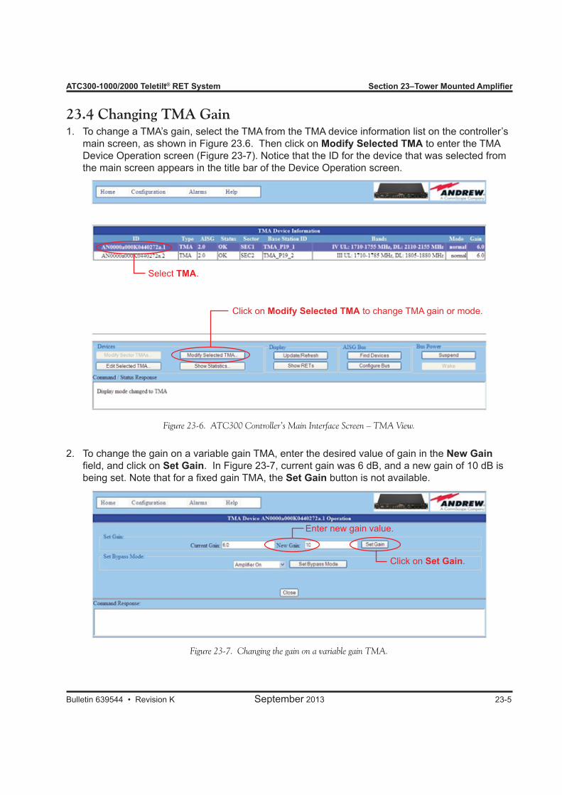
ATC300-1000/2000 Teletilt® RET System Section 23–Tower Mounted Amplifier
Bulletin 639544 • Revision K September 2013 23-5
23.4 Changing TMA GainTo change a TMA’s gain, select the TMA from the TMA device information list on the controller’s 1. main screen, as shown in Figure 23.6. Then click on Modify Selected TMA to enter the TMA Device Operation screen (Figure 23-7). Notice that the ID for the device that was selected from the main screen appears in the title bar of the Device Operation screen.
To change the gain on a variable gain TMA, enter the desired value of gain in the 2. New Gain field, and click on Set Gain. In Figure 23-7, current gain was 6 dB, and a new gain of 10 dB is being set. Note that for a fixed gain TMA, the Set Gain button is not available.
Select TMA.
Click on Modify Selected TMA to change TMA gain or mode.
Figure 23-6. ATC300 Controller’s Main Interface Screen – TMA View.
Figure 23-7. Changing the gain on a variable gain TMA.
Enter new gain value.
Click on Set Gain.
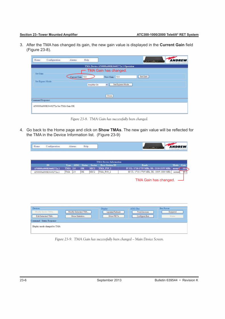
Section 23–Tower Mounted Amplifier ATC300-1000/2000 Teletilt® RET System
23-6 September 2013 Bulletin 639544 • Revision K
After the TMA has changed its gain, the new gain value is displayed in the 3. Current Gain field (Figure 23-8).
Go back to the Home page and click on 4. Show TMAs. The new gain value will be reflected for the TMA in the Device Information list. (Figure 23-9)
TMA Gain has changed.
Figure 23-8. TMA Gain has successfully been changed.
Figure 23-9. TMA Gain has successfully been changed – Main Device Screen.
TMA Gain has changed.
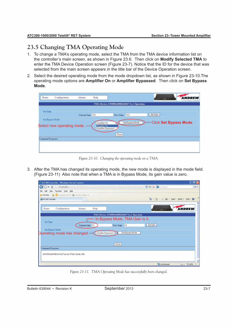
ATC300-1000/2000 Teletilt® RET System Section 23–Tower Mounted Amplifier
Bulletin 639544 • Revision K September 2013 23-7
23.5 Changing TMA Operating ModeTo change a TMA’s operating mode, select the TMA from the TMA device information list on 1. the controller’s main screen, as shown in Figure 23.6. Then click on Modify Selected TMA to enter the TMA Device Operation screen (Figure 23-7). Notice that the ID for the device that was selected from the main screen appears in the title bar of the Device Operation screen. Select the desired operating mode from the mode dropdown list, as shown in Figure 23-10.The 2. operating mode options are Amplifier On or Amplifier Bypassed. Then click on Set Bypass Mode.
Select new operating mode.Click Set Bypass Mode.
Figure 23-10. Changing the operating mode on a TMA.
After the TMA has changed its operating mode, the new mode is displayed in the mode field. 3. (Figure 23-11) Also note that when a TMA is in Bypass Mode, its gain value is zero.
Figure 23-11. TMA Operating Mode has successfully been changed.
In Bypass Mode, TMA Gain is 0.
Operating mode has changed.
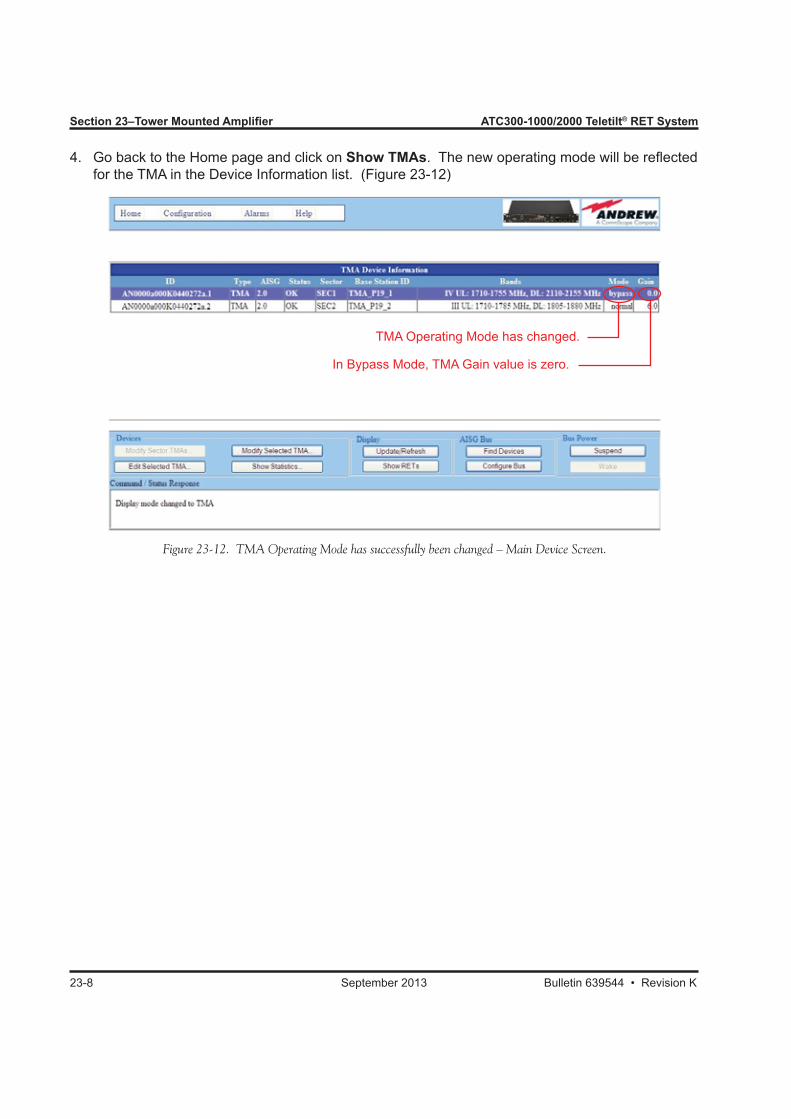
Section 23–Tower Mounted Amplifier ATC300-1000/2000 Teletilt® RET System
23-8 September 2013 Bulletin 639544 • Revision K
Go back to the Home page and click on 4. Show TMAs. The new operating mode will be reflected for the TMA in the Device Information list. (Figure 23-12)
TMA Operating Mode has changed.
In Bypass Mode, TMA Gain value is zero.
Figure 23-12. TMA Operating Mode has successfully been changed – Main Device Screen.

Bulletin 639544 • Revision K September 2013
Part 9Helpful Information

Part 9–Helpful Information
September 2013 Bulletin 639544 • Revision K
ATC300-1000/2000 Teletilt® RET System
This page intentionally left blank.
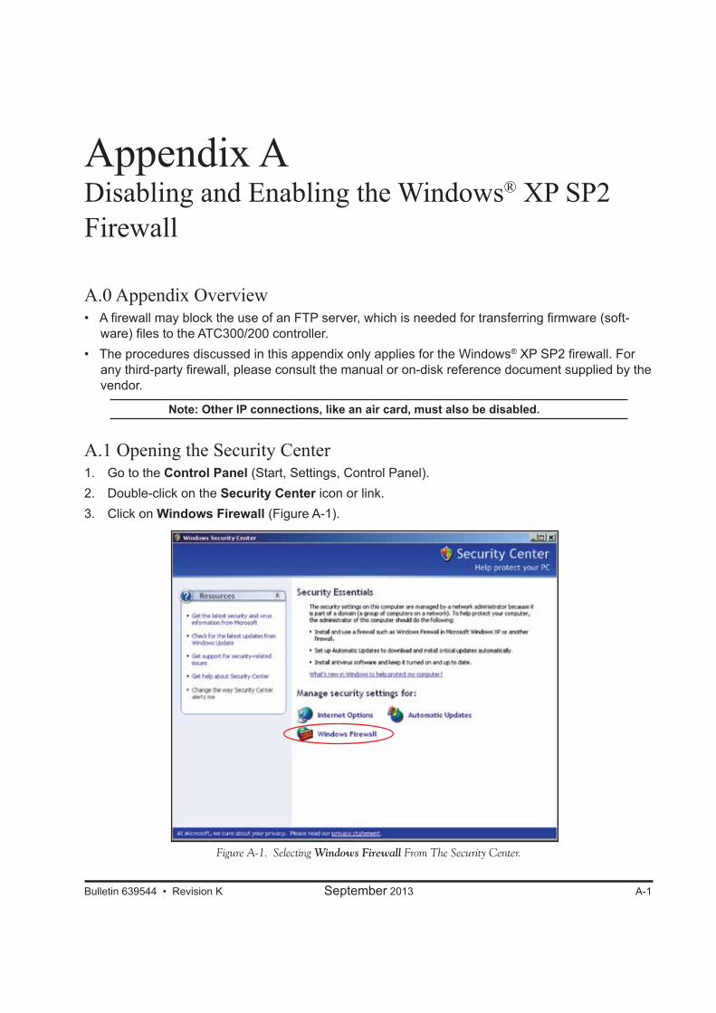
Appendix ADisabling and Enabling the Windows® XP SP2 Firewall
A.0 Appendix Overview• A firewall may block the use of an FTP server, which is needed for transferring firmware (soft-
ware) files to the ATC300/200 controller.• The procedures discussed in this appendix only applies for the Windows® XP SP2 firewall. For
any third-party firewall, please consult the manual or on-disk reference document supplied by the vendor.
Note: Other IP connections, like an air card, must also be disabled.
A.1 Opening the Security Center1. Go to the Control Panel (Start, Settings, Control Panel).2. Double-click on the Security Center icon or link.3. Click on Windows Firewall (Figure A-1).
Bulletin 639544 • Revision K September 2013 A-1
Figure A-1. Selecting Windows Firewall From The Security Center.
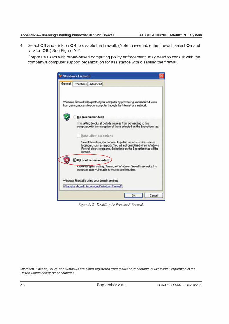
Appendix A–Disabling/Enabling Windows® XP SP2 Firewall ATC300-1000/2000 Teletilt® RET System
A-2 September 2013 Bulletin 639544 • Revision K
4. Select Off and click on OK to disable the firewall. (Note to re-enable the firewall, select On and click on OK.) See Figure A-2.
Corporate users with broad-based computing policy enforcement, may need to consult with the company’s computer support organization for assistance with disabling the firewall.
Figure A-2. Disabling the Windows® Firewall.
Microsoft, Encarta, MSN, and Windows are either registered trademarks or trademarks of Microsoft Corporation in the United States and/or other countries.
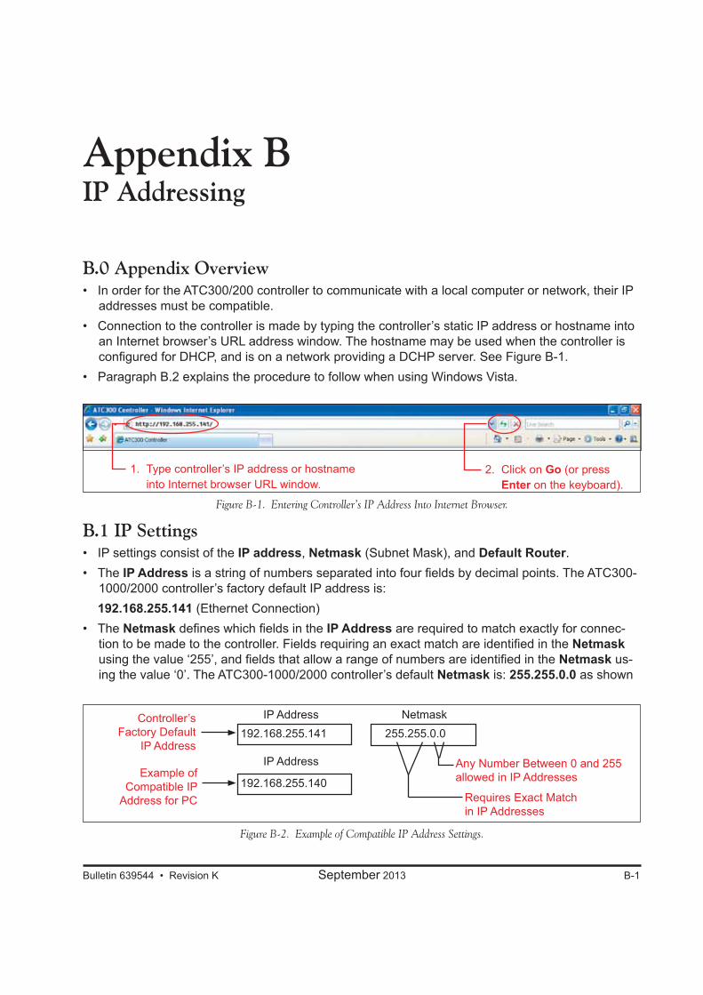
Bulletin 639544 • Revision K September 2013 B-1
Appendix BIP Addressing
B.0 Appendix Overview• In order for the ATC300/200 controller to communicate with a local computer or network, their IP
addresses must be compatible.• Connection to the controller is made by typing the controller’s static IP address or hostname into
an Internet browser’s URL address window. The hostname may be used when the controller is configured for DHCP, and is on a network providing a DCHP server. See Figure B-1.
• Paragraph B.2 explains the procedure to follow when using Windows Vista.
Figure B-1. Entering Controller’s IP Address Into Internet Browser.
B.1 IP Settings • IP settings consist of the IP address, Netmask (Subnet Mask), and Default Router. • The IP Address is a string of numbers separated into four fields by decimal points. The ATC300-
1000/2000 controller’s factory default IP address is: 192.168.255.141 (Ethernet Connection) • The Netmask defines which fields in the IP Address are required to match exactly for connec-
tion to be made to the controller. Fields requiring an exact match are identified in the Netmask using the value ‘255’, and fields that allow a range of numbers are identified in the Netmask us-ing the value ‘0’. The ATC300-1000/2000 controller’s default Netmask is: 255.255.0.0 as shown
Figure B-2. Example of Compatible IP Address Settings.
192.168.255.141 255.255.0.0IP Address
IP Address
Netmask
Example of Compatible IP
Address for PC
Controller’sFactory Default
IP Address
Requires Exact Match in IP Addresses
Any Number Between 0 and 255 allowed in IP Addresses192.168.255.140
1. Type controller’s IP address or hostname into Internet browser URL window.
2. Click on Go (or press Enter on the keyboard).
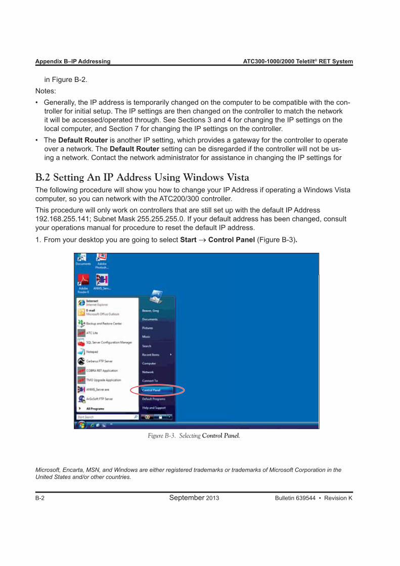
Appendix B–IP Addressing ATC300-1000/2000 Teletilt® RET System
B-2 September 2013 Bulletin 639544 • Revision K
in Figure B-2. Notes:• Generally, the IP address is temporarily changed on the computer to be compatible with the con-
troller for initial setup. The IP settings are then changed on the controller to match the network it will be accessed/operated through. See Sections 3 and 4 for changing the IP settings on the local computer, and Section 7 for changing the IP settings on the controller.
• The Default Router is another IP setting, which provides a gateway for the controller to operate over a network. The Default Router setting can be disregarded if the controller will not be us-ing a network. Contact the network administrator for assistance in changing the IP settings for
Microsoft, Encarta, MSN, and Windows are either registered trademarks or trademarks of Microsoft Corporation in the United States and/or other countries.
B.2 Setting An IP Address Using Windows VistaThe following procedure will show you how to change your IP Address if operating a Windows Vista computer, so you can network with the ATC200/300 controller.This procedure will only work on controllers that are still set up with the default IP Address 192.168.255.141; Subnet Mask 255.255.255.0. If your default address has been changed, consult your operations manual for procedure to reset the default IP address.
From your desktop you are going to select 1. Start → Control Panel (Figure B-3).
Figure B-3. Selecting Control Panel.

ATC300-1000/2000 Teletilt® RET System Appendix B–IP Addressing
Bulletin 639544 • Revision K September 2013 B-3
Figure B-4. Selecting Network and Sharing Center.
Figure B-5. Selecting Manage Network Connections.
Click on 2. Network and Sharing Center (Figure B-4).
Select 3. Manage Network Connections link (Figure B-5).

Appendix B–IP Addressing ATC300-1000/2000 Teletilt® RET System
B-4 September 2013 Bulletin 639544 • Revision K
Figure B-6. Selecting Local Area Connection.
Figure B-7. Local Area Connection Status. Figure B-8. Local Area Connection Properties.
Click on 4. Local Area Connection (Figure B-6). This may appear differently on your computer. Ensure that you are using the connection that represents your RJ-45 port on the back of your computer.
Your 5. Local Area Connection Status window will open. Select Properties (Figure B-7).Double click 6. Internet Protocol Version 4 (TCP/IPv4). See Figure B-8.
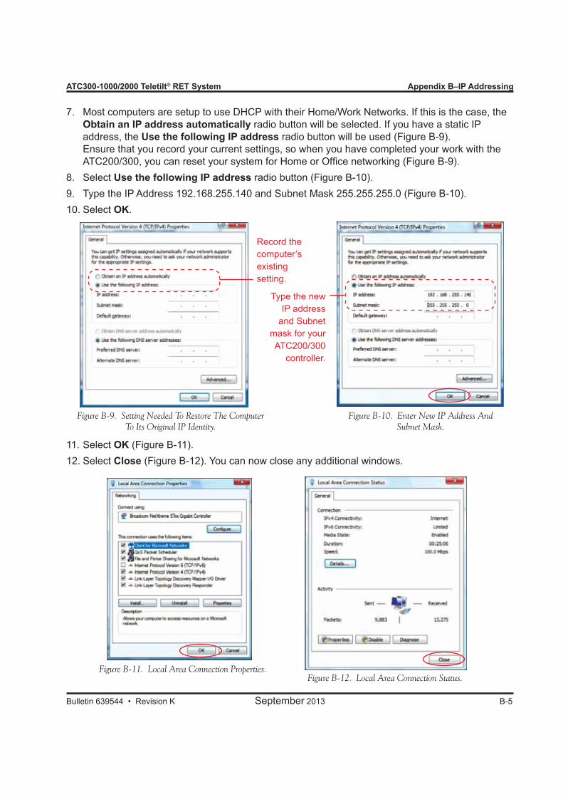
ATC300-1000/2000 Teletilt® RET System Appendix B–IP Addressing
Bulletin 639544 • Revision K September 2013 B-5
Figure B-11. Local Area Connection Properties.Figure B-12. Local Area Connection Status.
Most computers are setup to use DHCP with their Home/Work Networks. If this is the case, the 7. Obtain an IP address automatically radio button will be selected. If you have a static IP address, the Use the following IP address radio button will be used (Figure B-9). Ensure that you record your current settings, so when you have completed your work with the ATC200/300, you can reset your system for Home or Office networking (Figure B-9).
Select 8. Use the following IP address radio button (Figure B-10).Type the IP Address 192.168.255.140 and Subnet Mask 255.255.255.0 (Figure B-10).9. Select 10. OK.
Select 11. OK (Figure B-11).Select 12. Close (Figure B-12). You can now close any additional windows.
Figure B-10. Enter New IP Address And Subnet Mask.
Figure B-9. Setting Needed To Restore The Computer To Its Original IP Identity.
Record the computer’s existing setting.
Type the new IP address
and Subnet mask for your ATC200/300
controller.
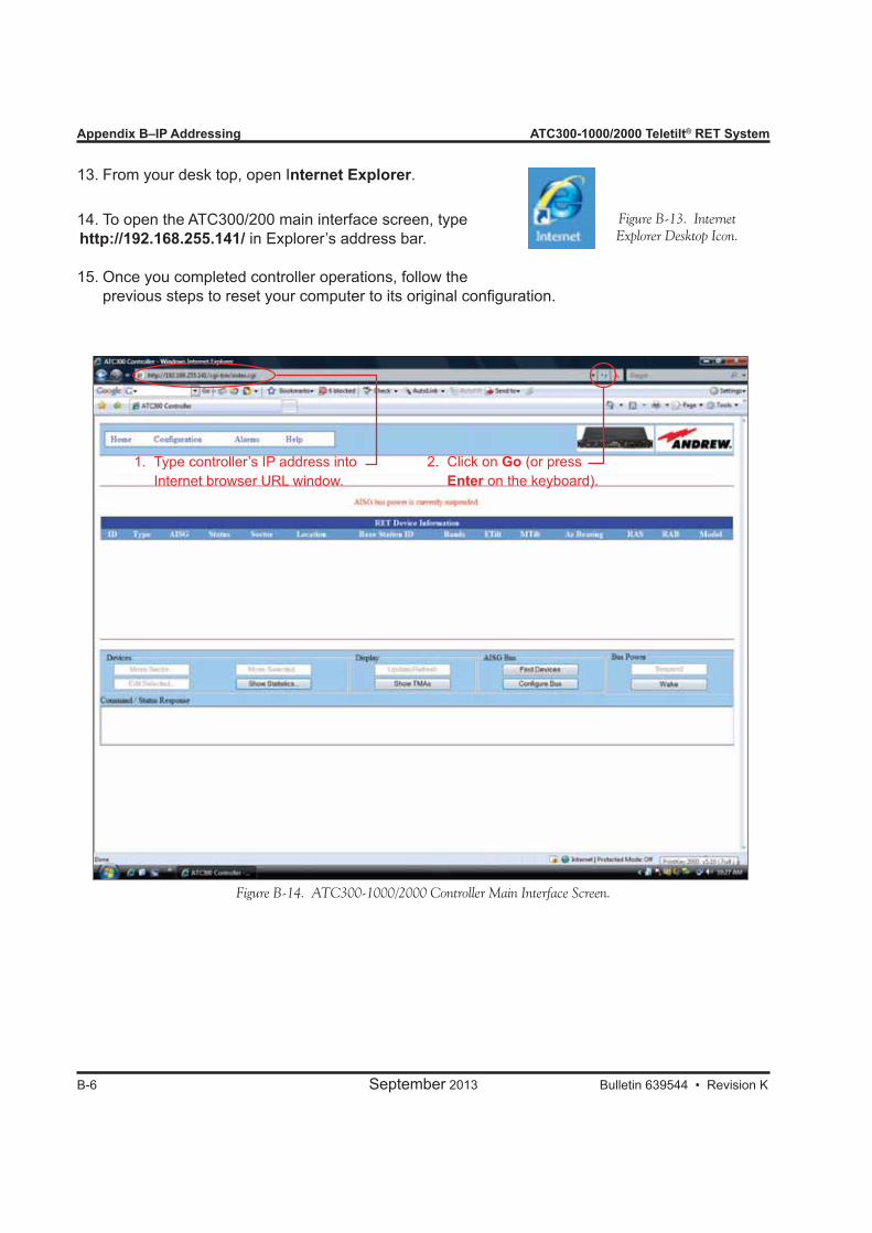
Appendix B–IP Addressing ATC300-1000/2000 Teletilt® RET System
B-6 September 2013 Bulletin 639544 • Revision K
From your desk top, open I13. nternet Explorer.
To open the ATC300/200 main interface screen, type 14. http://192.168.255.141/ in Explorer’s address bar.
Once you completed controller operations, follow the 15. previous steps to reset your computer to its original configuration.
Figure B-14. ATC300-1000/2000 Controller Main Interface Screen.
Figure B-13. Internet Explorer Desktop Icon.
1. Type controller’s IP address into Internet browser URL window.
2. Click on Go (or press Enter on the keyboard).
Bulletin 639544 • Revision K September 2013 C-1
Appendix CUploading the Firmware Manually
C.0 Section Overview• The screens shown in this section are examples from a Windows® XP PC that have been config-
ured to display the ‘Classic’ interface and is using Internet Explorer. Screens may differ with other versions of Windows®.
• Netscape and Mozilla web browsers are not supported by the ATC300/ATC200.• ATC300 version 2.34 (and later) does not require an FTP (file transfer protocol) server to upload
files to the controller or to an AISG device connected to the controller.• ATC200 controllers and ATC300 with software version 2.32 and earlier require an FTP server to
upload the firmware files (including the latest antenna definition file) to the controller and AISG devices.
• The IP Config Tool can be used as the FTP server. (If the PC and controller are already connected, it is not necessary to use the New IP Info tab. Directly choose the FTP Server tab in the IP Config Tool window). See Section 9.3. Another FTP application may be used as long as it provides the same functionality. Andrew cannot guarantee the functionality of an FTP server application.
• The Windows® XP Service Pack 2 firewall has been found to sometimes interfere with the FTP Server application (see Appendix A for instructions on disabling/enabling this firewall).
• Periodically, updates are made to the antenna definition file to add data for new antenna models and to maintain the latest data available for existing antennas compatible for the controller system. ATC300 firmware release 2.21_A and ATC200 firmware release 464A8_A introduces “bundled” firmware. These updates are made automatically when the operator installs new controller firmware, because antenna definition file releases are bundled with controller firmware.
• To receive automated notifications for new releases available for ATC300/ATM200 software, An-drew Solutions has provided an online registration at the Andrew web site (www.commscope.com). Link to Andrew→Products→Antennas→Teletilt RET System→Downloads→Downloadable Firmware, Software, Tools, and Manuals and you will be prompted to complete the registration online.
• After software upgrades are complete, operations may slightly vary from what is described in this document.
Warning: The ATC300-2000 controller unit requires software release 2.36 or later. Conversely, however, software release 2.36 and later can be installed on ATC300-1000 control-
ler units. All new features and/or bug fixes provided with the controller software will be available on the ATC300-1000 with the exception of modem port isolation, which is not supported on the ATC300-1000 hardware.
Microsoft, Encarta, MSN, and Windows are either registered trademarks or trademarks of Microsoft Corporation in the United States and/or other countries.
Appendix C–Uploading Firmware Manually ATC300-1000/2000 Teletilt® RET System
C-2 September 2013 Bulletin 639544 • Revision K
C.1 Required ResourcesHardware1. ATC300-1000/2000 or ATC200-1000 controller w/power cord2. Ethernet cable (or LAN connectivity between the controller and FTP Server PC)3. One or more AISG-compliant ALDs connected to the controller using AISG-compliant RET ca-
blingSoftware1. FTP application (not required for ATC300 2.34 and later)2. ATC300 controller firmware (to be uploaded into the controller): (atc300_*.tar or ATC200 con-
troller firmware ( RET-AN-AT_*.ascu)3. Appropriate device firmware (to be uploaded into the AISG devices)4. Antenna definition files (RET-XX-AT_*.ascu)Asterisk (*) represents the version number. Use the file with the highest number preceding the file extension for each type file to ensure the latest version data is uploaded.
C.2 Installing, Configuring, and Running the FTP Server (not needed for ATC300 2.34 and later)Note that the following instructions apply only to the ArGoSoft FTP Server.1. Create a directory named ATC200 on the PC’s hard drive. Place the FTP software zip file (fssetup.zip) in the ATC200 directory. The fssetup.zip file is available on the web at www.argosoft.com.2. Double-click on fssetup.zip to unzip the FTP software files. Specify the ATC200 directory for the destination to store the extracted files. In some cases, installation may begin after double-clicking on the zip file. If this occurs, follow the prompts, accepting the suggested defaults, to complete the installation.3. If installation did not begin automatically upon executing the zip file, double-click on the setup.exe file for the FTP software (stored in the ATC200 directory). Follow the prompts, accepting the suggested defaults, to complete the installation.4. If the defaults suggested during installation were accepted, an icon for the FTP server should be on your desktop. Double-click on the ArGoSoft FTP Server icon5. Go to Tools\Users to open the User Setup configuration dialog box.6. Click on the Add New User icon in the dialog’s tool bar (the far left icon).
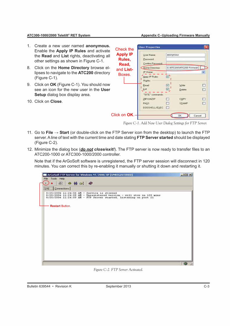
ATC300-1000/2000 Teletilt® RET System Appendix C–Uploading Firmware Manually
Bulletin 639544 • Revision K September 2013 C-3
1. Create a new user named anonymous. Enable the Apply IP Rules and activate the Read and List rights, deactivating all other settings as shown in Figure C-1.
8. Click on the Home Directory browse el-lipses to navigate to the ATC200 directory (Figure C-1).
9. Click on OK (Figure C-1). You should now see an icon for the new user in the User Setup dialog box display area.
10. Click on Close.
Check theApply IPRules, Read,
and List-Boxes.
Click on OK.
Figure C-1. Add New User Dialog Settings for FTP Server.
11. Go to File → Start (or double-click on the FTP Server icon from the desktop) to launch the FTP server. A line of text with the current time and date stating FTP Server started should be displayed (Figure C-2).
12. Minimize the dialog box (do not close/exit!). The FTP server is now ready to transfer files to an ATC200-1000 or ATC300-1000/2000 controller.
Note that if the ArGoSoft software is unregistered, the FTP server session will disconnect in 120 minutes. You can correct this by re-enabling it manually or shutting it down and restarting it.
Figure C-2. FTP Server Activated.
Restart Button.
Appendix C–Uploading Firmware Manually ATC300-1000/2000 Teletilt® RET System
C-4 September 2013 Bulletin 639544 • Revision K
C.3 Uploading the Firmware Bundle to the Controller1. Download the controller firmware bundle from the CommScope web site. From the
Andrew→Products tab on www.commscope.com, click on Andrew→Products→Antennas→ Teletilt RET System→Downloads→RET Contrller Software and Firmware Store the files in the root directory for the FTP Server. Note that if the files are zipped, double-click on the zip files to extract the files into the FTP Server root directory.
The file that may be uploaded to an ATC300-1000/2000 controller is: • System Firmware Build (atc300_*.tar) The file that may be uploaded to an ATC200-1000 controller is: • System Firmware Build (RET-AN-RT_*.ascu) An asterisk (*) shown in sample firmware filenames represents the firmware version number. Text
preceding the version number in the file name will always be consistent and is used to identify the file type. See paragraph C.4 to verify the version numbers for the currently installed control-ler firmware. It may be necessary to type the filenames in with exact upper and lower case lettering, as some FTP servers are sensitive to capitalization for file recognition.
2. Ensure that the controller is connected and configured to the same Ethernet network that the PC, running the FTP server, is on. If the PC running the FTP server is on a different network from the one that was used to configure the controller in Section 4, the controller’s IP address-ing will need to be temporarily re-configured for the FTP connection. Contact a network admin-istrator for assistance, if needed.To test this connection, start your Internet browser on the PC that is running the FTP Server. Type the controller’s Ethernet IP address (compatible with the network running the FTP Server) into the URL window. If the connection is successful, the con-troller’s main screen will be displayed in the browser.
3. From the controller’s main interface screen, go to Configuration→Software Config.4. (ATC300 2.34 and later) Select Install System File, navigate to and select the file to upload to
the controller. (Figure C-3)
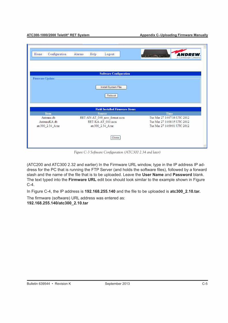
ATC300-1000/2000 Teletilt® RET System Appendix C–Uploading Firmware Manually
Bulletin 639544 • Revision K September 2013 C-5
(ATC200 and ATC300 2.32 and earlier) In the Firmware URL window, type in the IP address IP ad-dress for the PC that is running the FTP Server (and holds the software files), followed by a forward slash and the name of the file that is to be uploaded. Leave the User Name and Password blank. The text typed into the Firmware URL edit box should look similar to the example shown in Figure C-4.In Figure C-4, the IP address is 192.168.255.140 and the file to be uploaded is atc300_2.10.tar. The firmware (software) URL address was entered as:192.168.255.140/atc300_2.10.tar
Figure C-3 Software Configuration (ATC300 2.34 and later)
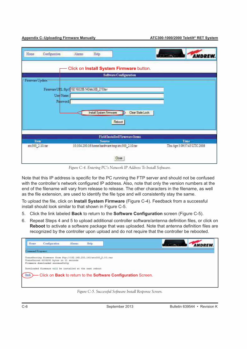
Appendix C–Uploading Firmware Manually ATC300-1000/2000 Teletilt® RET System
C-6 September 2013 Bulletin 639544 • Revision K
Note that this IP address is specific for the PC running the FTP server and should not be confused with the controller’s network configured IP address. Also, note that only the version numbers at the end of the filename will vary from release to release. The other characters in the filename, as well as the file extension, are used to identify the file type and will consistently stay the same. To upload the file, click on Install System Firmware (Figure C-4). Feedback from a successful install should look similar to that shown in Figure C-5.5. Click the link labeled Back to return to the Software Configuration screen (Figure C-5). 6. Repeat Steps 4 and 5 to upload additional controller software/antenna definition files, or click on
Reboot to activate a software package that was uploaded. Note that antenna definition files are recognized by the controller upon upload and do not require that the controller be rebooted.
Figure C-4. Entering PC’s Network IP Address To Install Software.
Figure C-5. Successful Software Install Response Screen.
Click on Back to return to the Software Configuration Screen.
Click on Install System Firmware button.
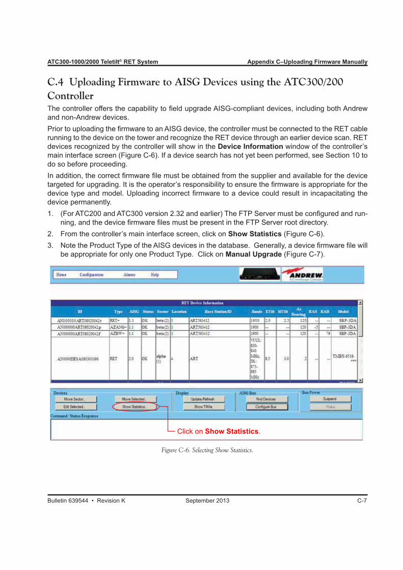
ATC300-1000/2000 Teletilt® RET System Appendix C–Uploading Firmware Manually
Bulletin 639544 • Revision K September 2013 C-7
C.4 Uploading Firmware to AISG Devices using the ATC300/200 ControllerThe controller offers the capability to field upgrade AISG-compliant devices, including both Andrew and non-Andrew devices.Prior to uploading the firmware to an AISG device, the controller must be connected to the RET cable running to the device on the tower and recognize the RET device through an earlier device scan. RET devices recognized by the controller will show in the Device Information window of the controller’s main interface screen (Figure C-6). If a device search has not yet been performed, see Section 10 to do so before proceeding.In addition, the correct firmware file must be obtained from the supplier and available for the device targeted for upgrading. It is the operator’s responsibility to ensure the firmware is appropriate for the device type and model. Uploading incorrect firmware to a device could result in incapacitating the device permanently.1. (For ATC200 and ATC300 version 2.32 and earlier) The FTP Server must be configured and run-
ning, and the device firmware files must be present in the FTP Server root directory.2. From the controller’s main interface screen, click on Show Statistics (Figure C-6).3. Note the Product Type of the AISG devices in the database. Generally, a device firmware file will
be appropriate for only one Product Type. Click on Manual Upgrade (Figure C-7).
Figure C-6. Selecting Show Statistics.
Click on Show Statistics.

Appendix C–Uploading Firmware Manually ATC300-1000/2000 Teletilt® RET System
C-8 September 2013 Bulletin 639544 • Revision K
4. Click on the check box(es) at the far right to select one or more devices for a sof tware upload. As noted in Step 2, the Product Type should be the same for all selected devices, and should be the targeted Product Type for the device firmware file. Note that uploads are performed in succession to each selected device. If several devices are selected, the entire upload process can be time-consuming. (Figure C-8a).
5. (For ATC200 and ATC300 version 2.32 and earlier) In the Firmware URL:ftp// field, type in the IP address of the PC that is running the FTP server (and holds the device firmware files), followed by a forward slash and the name of the file that is to be uploaded to the selected devices. If needed, enter a User Name and Password for the FTP server. Finally, click on Install Remote Firmware (Figure C-8a).
Figure C-7. Manually Upgrading AISG-Compliant Devices.
Click on Manual Upgrade
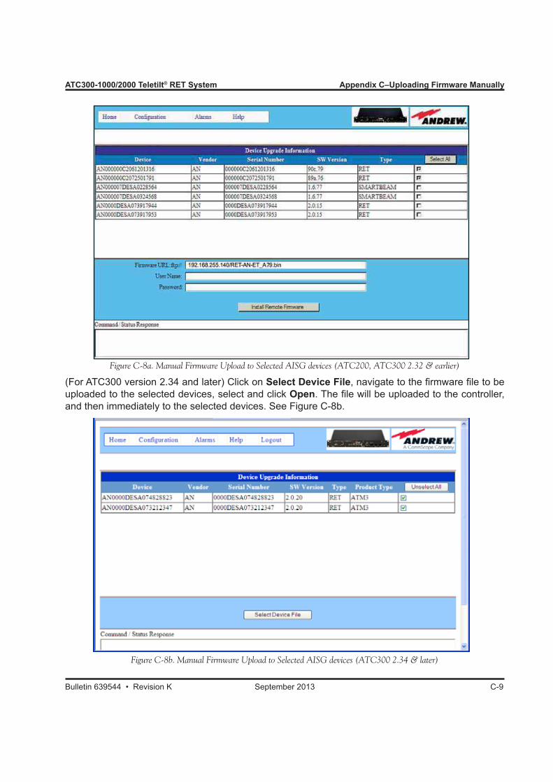
ATC300-1000/2000 Teletilt® RET System Appendix C–Uploading Firmware Manually
Bulletin 639544 • Revision K September 2013 C-9
Figure C-8a. Manual Firmware Upload to Selected AISG devices (ATC200, ATC300 2.32 & earlier)
Figure C-8b. Manual Firmware Upload to Selected AISG devices (ATC300 2.34 & later)
(For ATC300 version 2.34 and later) Click on Select Device File, navigate to the firmware file to be uploaded to the selected devices, select and click Open. The file will be uploaded to the controller, and then immediately to the selected devices. See Figure C-8b.
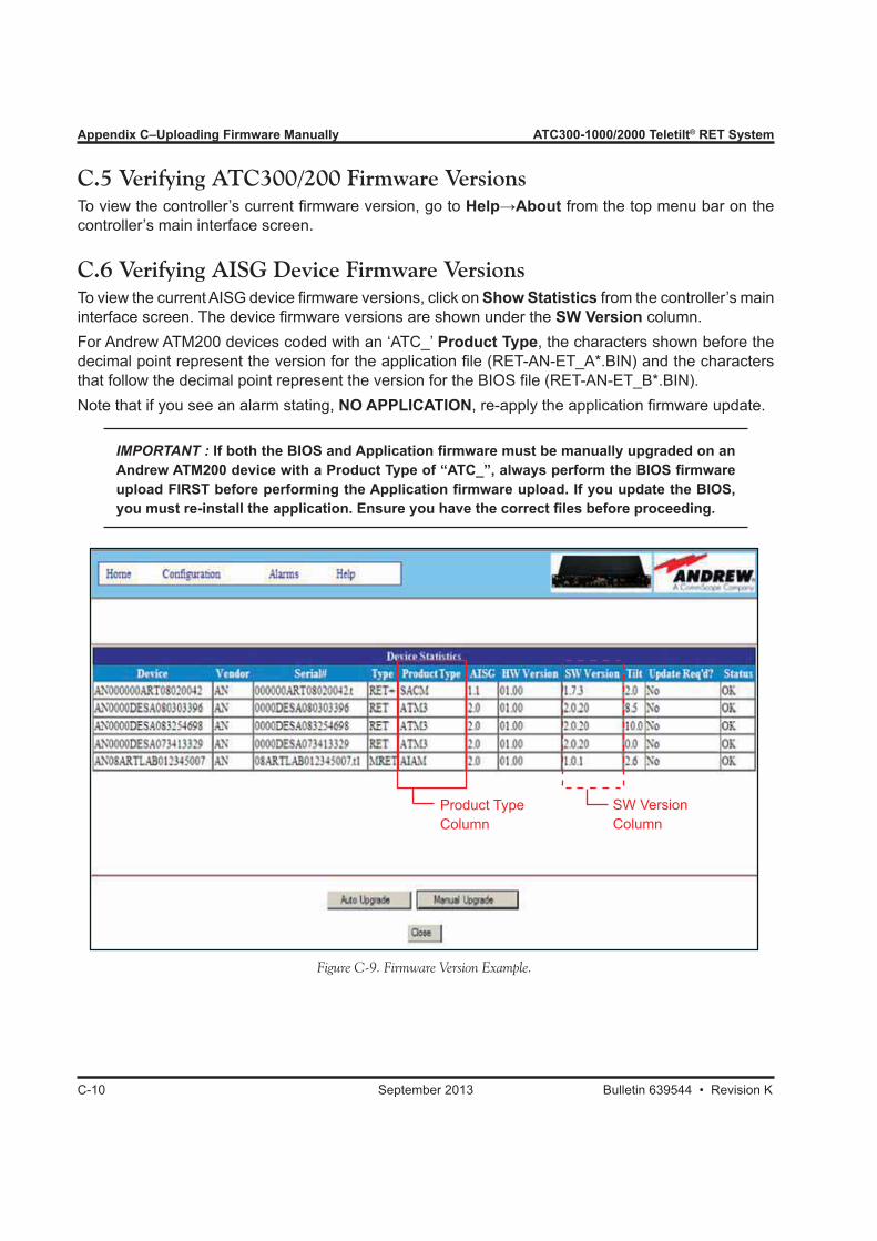
Appendix C–Uploading Firmware Manually ATC300-1000/2000 Teletilt® RET System
C-10 September 2013 Bulletin 639544 • Revision K
Figure C-9. Firmware Version Example.
C.5 Verifying ATC300/200 Firmware VersionsTo view the controller’s current firmware version, go to Help→About from the top menu bar on the controller’s main interface screen.
C.6 Verifying AISG Device Firmware VersionsTo view the current AISG device firmware versions, click on Show Statistics from the controller’s main interface screen. The device firmware versions are shown under the SW Version column.For Andrew ATM200 devices coded with an ‘ATC_’ Product Type, the characters shown before the decimal point represent the version for the application file (RET-AN-ET_A*.BIN) and the characters that follow the decimal point represent the version for the BIOS file (RET-AN-ET_B*.BIN).Note that if you see an alarm stating, NO APPLICATION, re-apply the application firmware update.
IMPORTANT : If both the BIOS and Application firmware must be manually upgraded on an Andrew ATM200 device with a Product Type of “ATC_”, always perform the BIOS firmware upload FIRST before performing the Application firmware upload. If you update the BIOS, you must re-install the application. Ensure you have the correct files before proceeding.
Product TypeColumn
SW VersionColumn

ATC300-1000/2000 Teletilt® RET System Appendix C–Uploading Firmware Manually
Bulletin 639544 • Revision K September 2013 C-11
This page intentionally left blank.
Bulletin 639544 • Revision K September 2013 D-1
D.0 Relay Alarm Definitions Table Major alarms that may be reported by a device are detailed in Table 1, next page.
D.1 Relay Alarm Information1. A major alarm relay can also be sent by the controller for the following conditions: • AISG_NO_REPLY Communication loss with one or more devices • POWER_STATUS Out of range current or voltage detected • INITIALIZATION_STATUS Occurs during controller startup2. The controller may also send minor alarm relays for the following condition: • DOWNLOAD_STATUS This condition is not an error. It indicates that the controller firmware is being downloaded.
Appendix DATC300-1000/2000 Relay Alarms

Appendix D–Relay Alarms ATC300-1000/2000 Teletilt® RET System
D-2 September 2013 Bulletin 639544 • Revision K
Meaning AISG1.0/1.1 AISG 2.0Actuator Detection Fail Signals from the actuator are detected but are ab-
normal or corrupted.
Actuator Jam Permanent Actuator cannot be moved. Actuator Jam Temporary Actuator jam has been detected. No movement
was temporarily detected in response to the normal stimulus.
Motor Jam Motor cannot move. ActuatorJam Actuator jam has been detected. No movement
of the actuator, but movement of the motor was detected.
EEPROM Error EEPROM error detected Flash Erase Error Used in combination with software download. Indi-
cates error when erasing flash memory.
Not Calibrated The device has not completed a calibration opera-tion, or calibration has been lost.
Not Scaled No setup table has been stored in the device. Not Configured Actuator configuration data is missing. Other Hardware Error Any hardware error which cannot be classified. Hardware Error Any hardware error which cannot be classified. May
not be reported as an alarm until the fault is likely to be persistent.
Other Software Error Any software error which cannot be classified. Position Lost RET controller is unable to return a correct position
value. For example, there was a power failure while a Set Tilt command was being executed.
RAM Error An error was detected in reading data to/from RAM. UART Error Hardware specific. This error may be sent after re-
covery from a temporary error which has prevented the sending or receiving of data.
TMA Alarm Minor An event has taken place that effects the TMA per-formance, the TMA continues to function, and by-pass is not implemented. (The actual performance degradation criteria must be vendor specified.)
TMA Alarm Major An event has taken place that renders TMA perfor-mance unacceptable. If bypass is fitted, the TMA will switch into bypass.
Bypass Mode A TMA band is set to bypass mode. Actuator Interference An actuator movement outside the control of the
RET unit has been detected. Probable cause is manual interference.
Table D-1. Relay Alarm Definitions.

Bulletin 639544 • Revision K September 2013 E-1
Appendix EDeclaration of Compliance
/2000

Appendix E–Declaration of Compliance ATC300-1000/2000 Teletilt® RET System
E-2 September 2013 Bulletin 639544 • Revision K
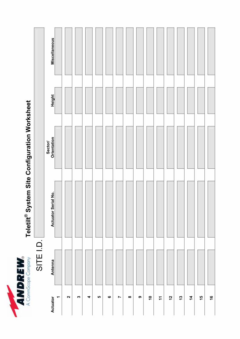
Te
letil
t® S
yste
m S
ite C
onfig
urat
ion
Wor
kshe
et
SIT
E I.
D.
Act
uato
r
Ant
enna
Act
uato
r Ser
ial N
o.
Se
ctor
/O
rient
atio
n
Hei
ght
M
isce
llane
ous
1 2 3 4 5 6 7 8 9 10 11 12 13 14 15 16
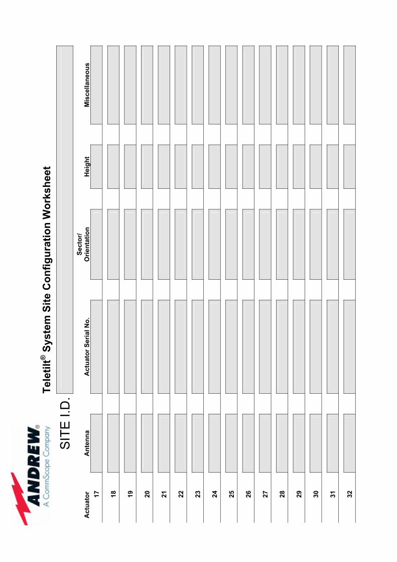
Te
letil
t® S
yste
m S
ite C
onfig
urat
ion
Wor
kshe
et
SIT
E I.
D.
Act
uato
r
Ant
enna
Act
uato
r Ser
ial N
o.
Se
ctor
/O
rient
atio
n
Hei
ght
M
isce
llane
ous
17 18 19 20 21 22 23 24 25 26 27 28 29 30 31 32