Embed Size (px)
DESCRIPTION
TELEPHONE NETWORK. Telephone networks use circuit switching. The telephone network had its beginnings in the late 1800s. The entire network, which is referred to as the plain old telephone system ( POTS ), was originally an analog system using analog signals to transmit voice. - PowerPoint PPT Presentation
Citation preview
TELEPHONE NETWORKTELEPHONE NETWORK
Telephone networks use circuit switching. The Telephone networks use circuit switching. The telephone network had its beginnings in the late telephone network had its beginnings in the late 1800s. The entire network, which is referred to as the 1800s. The entire network, which is referred to as the plain old telephone systemplain old telephone system ( (POTSPOTS), was originally an ), was originally an analog system using analog signals to transmit voice.analog system using analog signals to transmit voice.
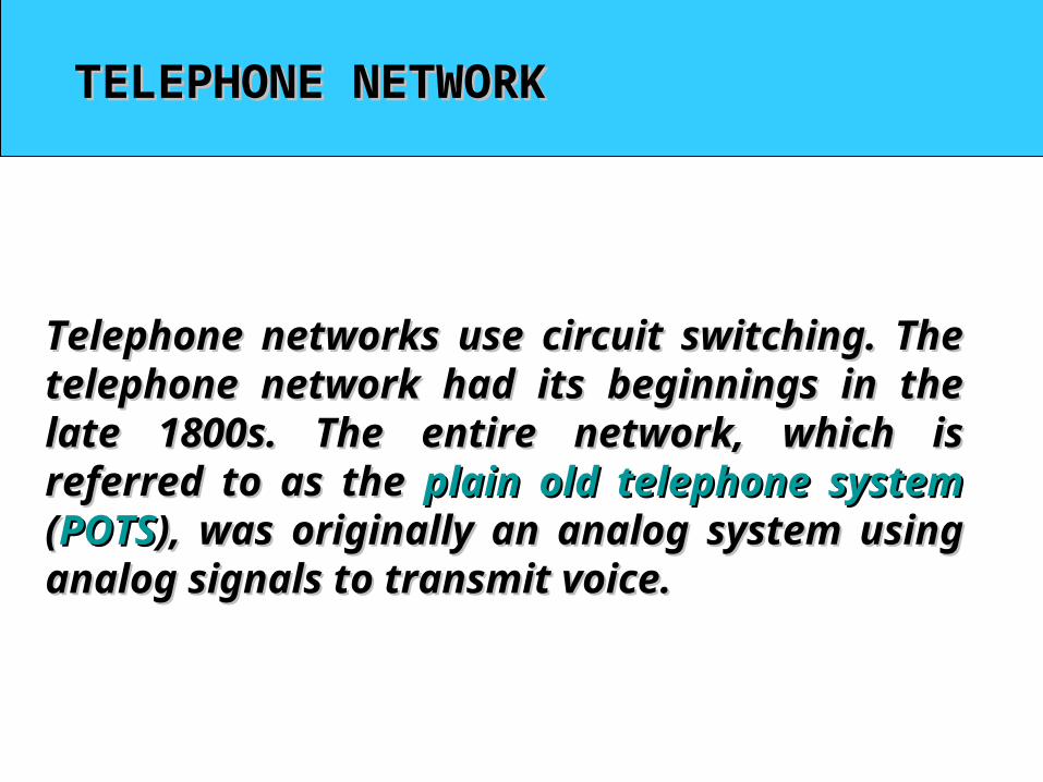
Public Circuit Switched Network
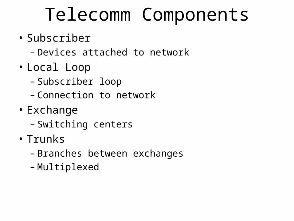
Telecomm Components• Subscriber
– Devices attached to network
• Local Loop– Subscriber loop– Connection to network
• Exchange– Switching centers
• Trunks– Branches between exchanges– Multiplexed
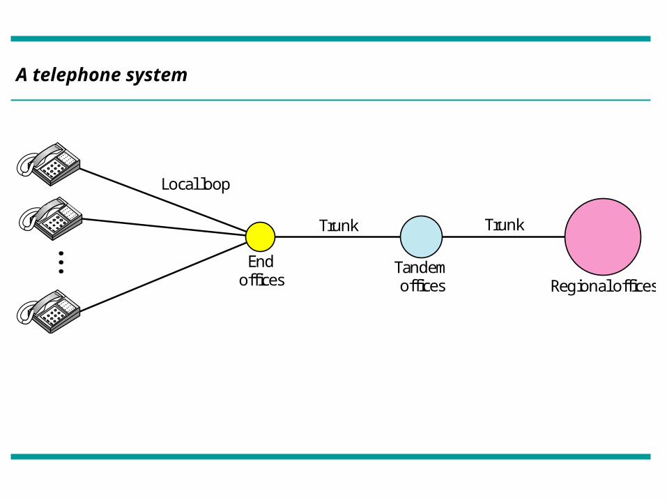
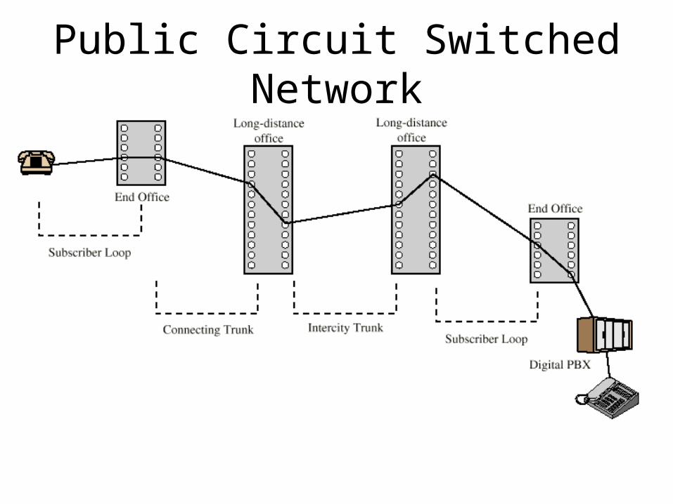
A telephone system
Endoffices
Local loop
Trunk
Tandemoffices Regional offices
Trunk
• • •
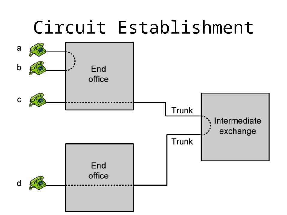
Circuit Establishment
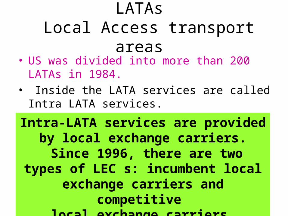
LATAs Local Access transport areas
• US was divided into more than 200 LATAs in 1984.
• Inside the LATA services are called Intra LATA services.
Intra-LATA services are provided by local exchange carriers.
Since 1996, there are twotypes of LEC s: incumbent local
exchange carriers and competitive local exchange carriers.
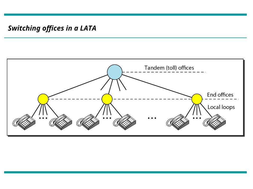
Switching offices in a LATA
Inter LATA Services
• The services between LATAs are handled by Interexchange carriers (IXCs).
• These carriers sometimes called long distance companies.
• Point of presence is the switching office to interact between IXC to LATA.
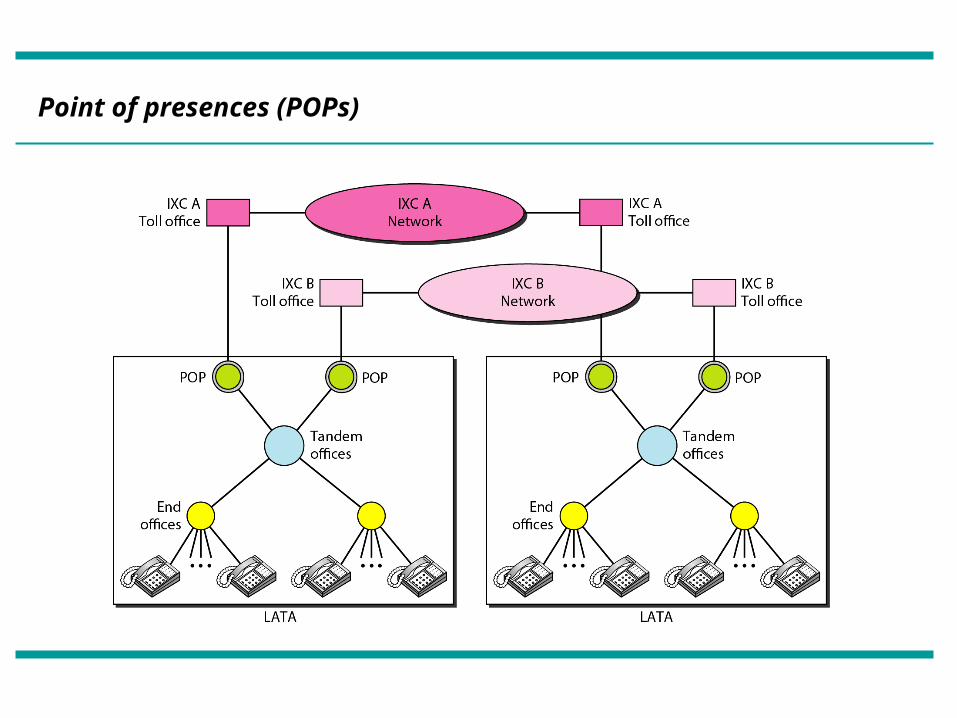
Point of presences (POPs)
The tasks of data transfer and signaling are separated in modern telephone
networks: data transfer is done by one network, signaling by another.
Note
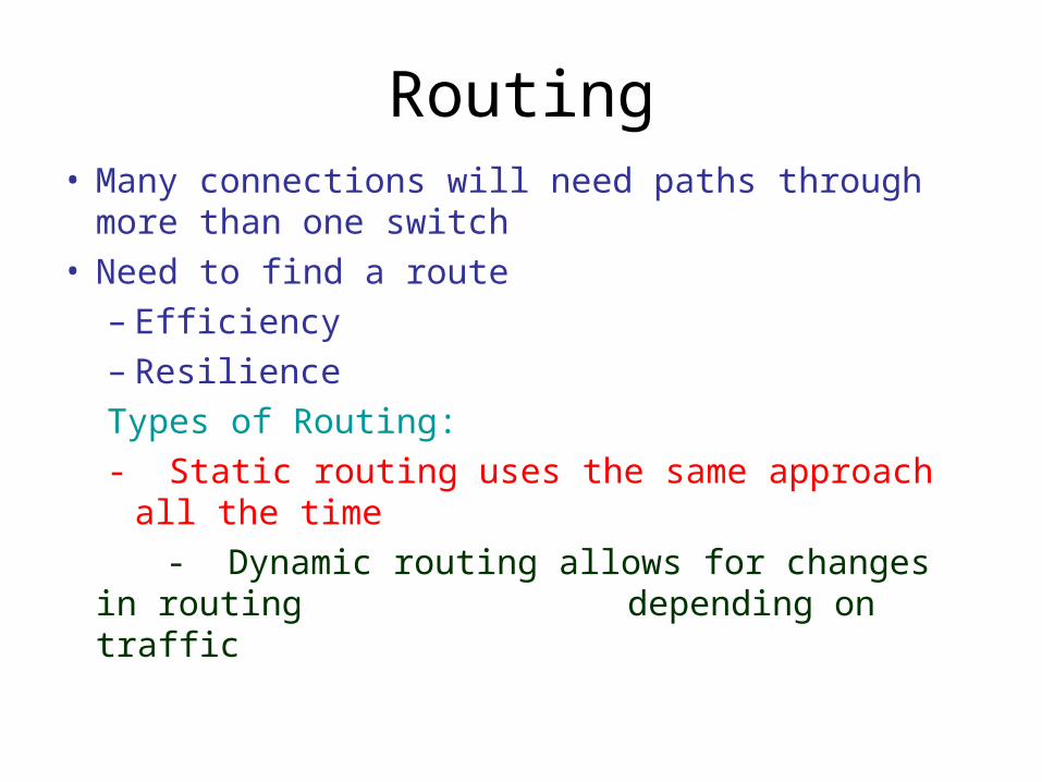
Routing• Many connections will need paths through more
than one switch• Need to find a route
– Efficiency– Resilience
Types of Routing:
- Static routing uses the same approach all the time
- Dynamic routing allows for changes in routing depending on traffic
Right through Alternate Routing
• Possible routes between end offices predefined
• Originating switch selects appropriate route
• Routes listed in preference order
• Different sets of routes may be used at different times
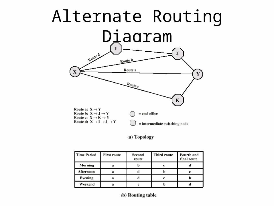
Alternate Routing Diagram
Own exchange routing
Own exchange routing or distributed routing allows alternative routes to be chosen at the intermediate nodes
Computer controlled routing
Separate computers are used for signaling & some algorithms are decided to chose the appropriate path.
Location of Signalling
Subscriber loop signalling:
Subscriber to network, Depends on subscriber device and switch
Intraexchange signalling:
In the exchange or switching system
Interexchange signalling:
Signalling between the exchanges
Control Signaling Functions• Audible communication with subscriber• Transmission of dialed number• Indication that call can not be completed • Call ended indication• Signal to ring phone• Billing info• Equipment and trunk status info• Control of specialist equipment
Control Signal Sequence• Both phones on hook• Subscriber lifts receiver (off hook)• End office switch signaled• Switch responds with dial tone• Caller dials number• If target not busy, send ringer signal to target subscriber• Feedback to caller
– Ringing tone, engaged tone, unobtainable• Target accepts call by lifting receiver• Switch terminates ringing signal and ringing tone• Switch establishes connection• Connection release when Source subscriber hangs up
Type of signaling
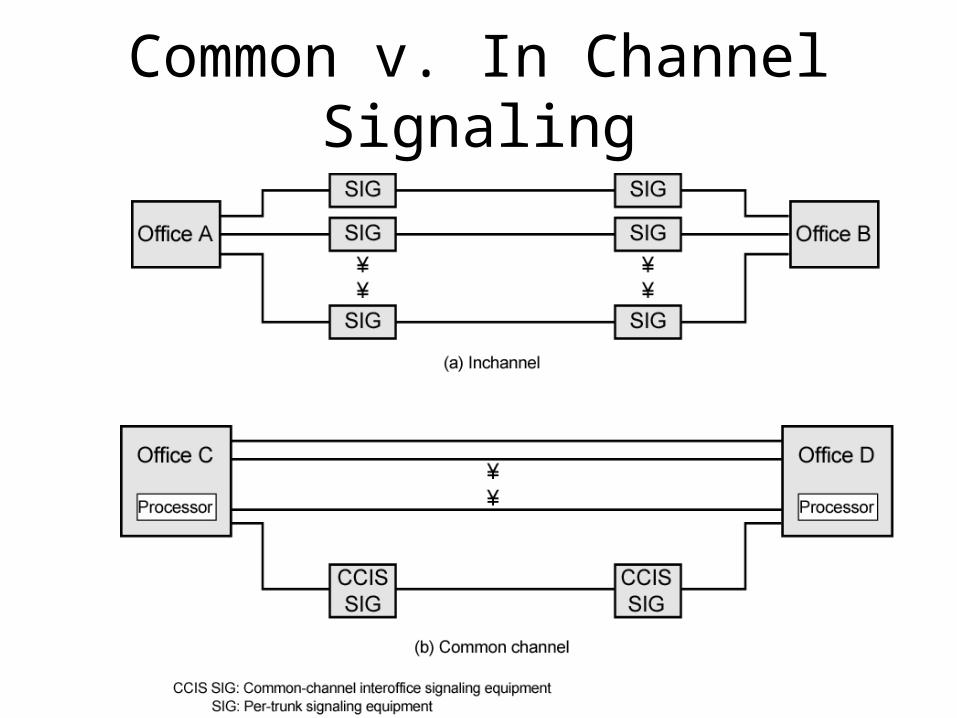
• In channel signaling
• Common channel signaling
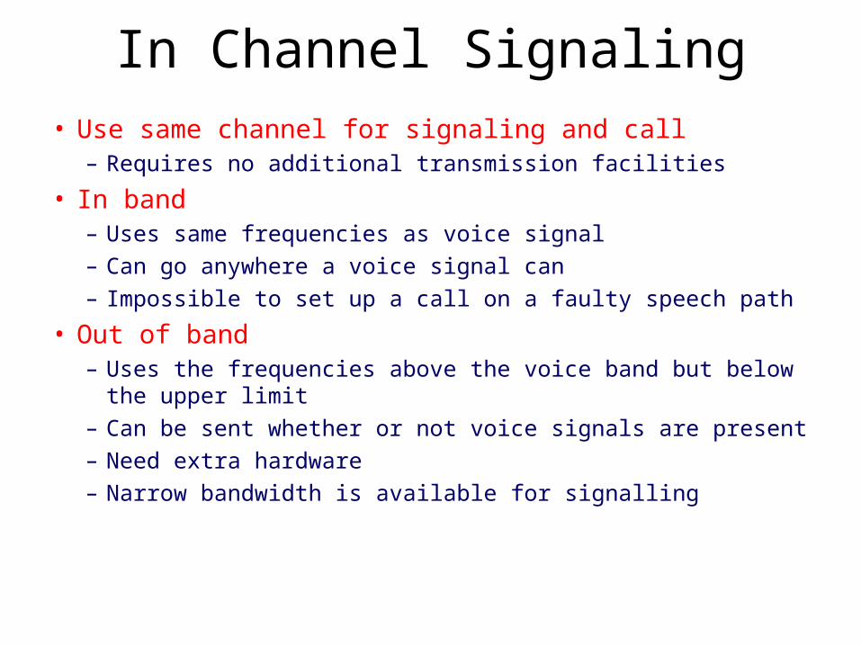
In Channel Signaling• Use same channel for signaling and call
– Requires no additional transmission facilities
• In band– Uses same frequencies as voice signal
– Can go anywhere a voice signal can
– Impossible to set up a call on a faulty speech path
• Out of band– Uses the frequencies above the voice band but below the upper
limit
– Can be sent whether or not voice signals are present
– Need extra hardware
– Narrow bandwidth is available for signalling
Drawbacks of In Channel Signaling
• Limited transfer rate
• Signalling capability is less
• Delay between entering address (dialing) and connection
• Overcome by use of common channel signaling
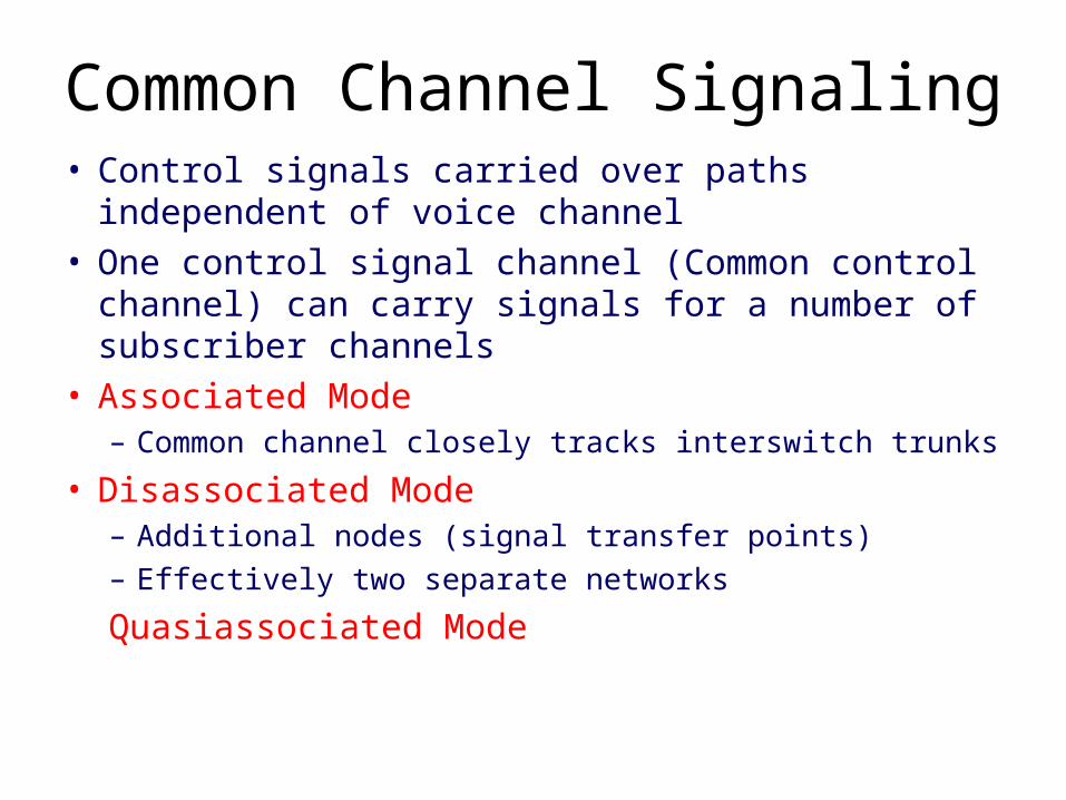
Common Channel Signaling• Control signals carried over paths independent of
voice channel• One control signal channel (Common control channel)
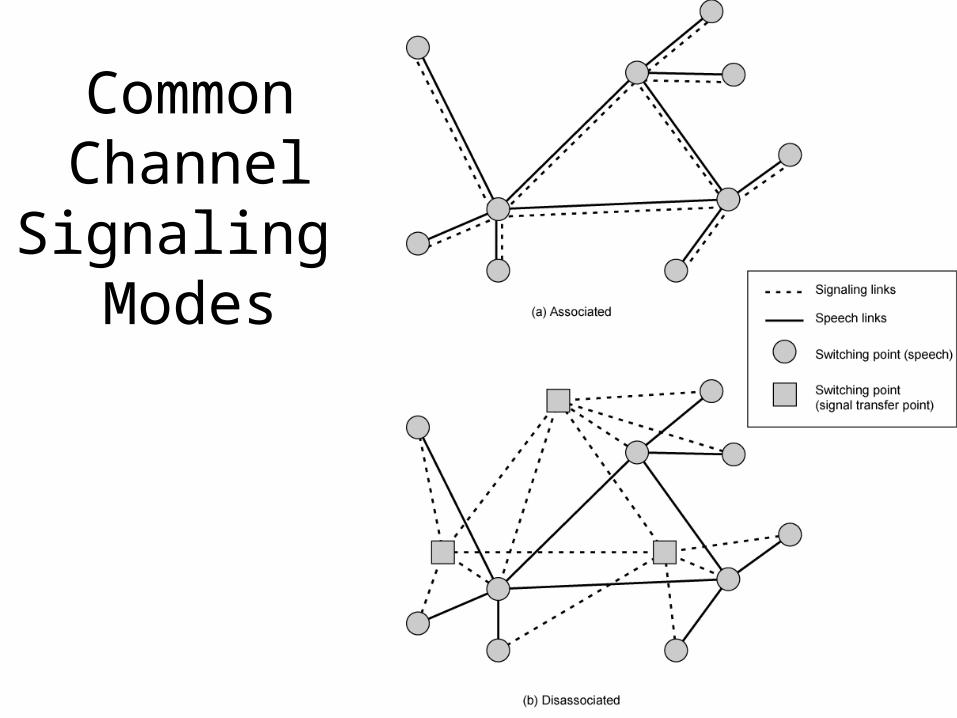
can carry signals for a number of subscriber channels• Associated Mode
– Common channel closely tracks interswitch trunks
• Disassociated Mode– Additional nodes (signal transfer points)– Effectively two separate networks
Quasiassociated Mode
Common v. In Channel Signaling
CommonChannel
Signaling Modes
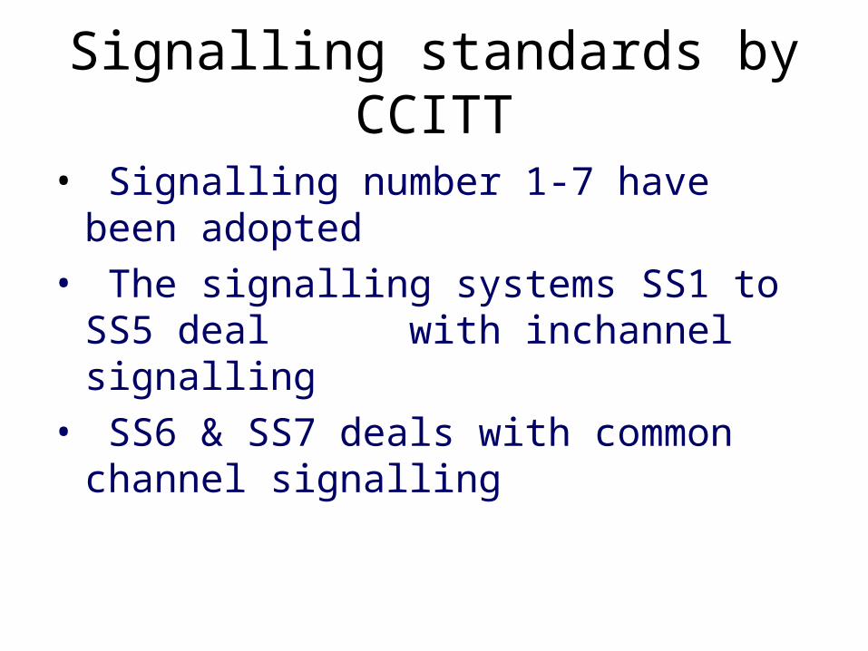
Signalling standards by CCITT
• Signalling number 1-7 have been adopted
• The signalling systems SS1 to SS5 deal with inchannel signalling
• SS6 & SS7 deals with common channel signalling
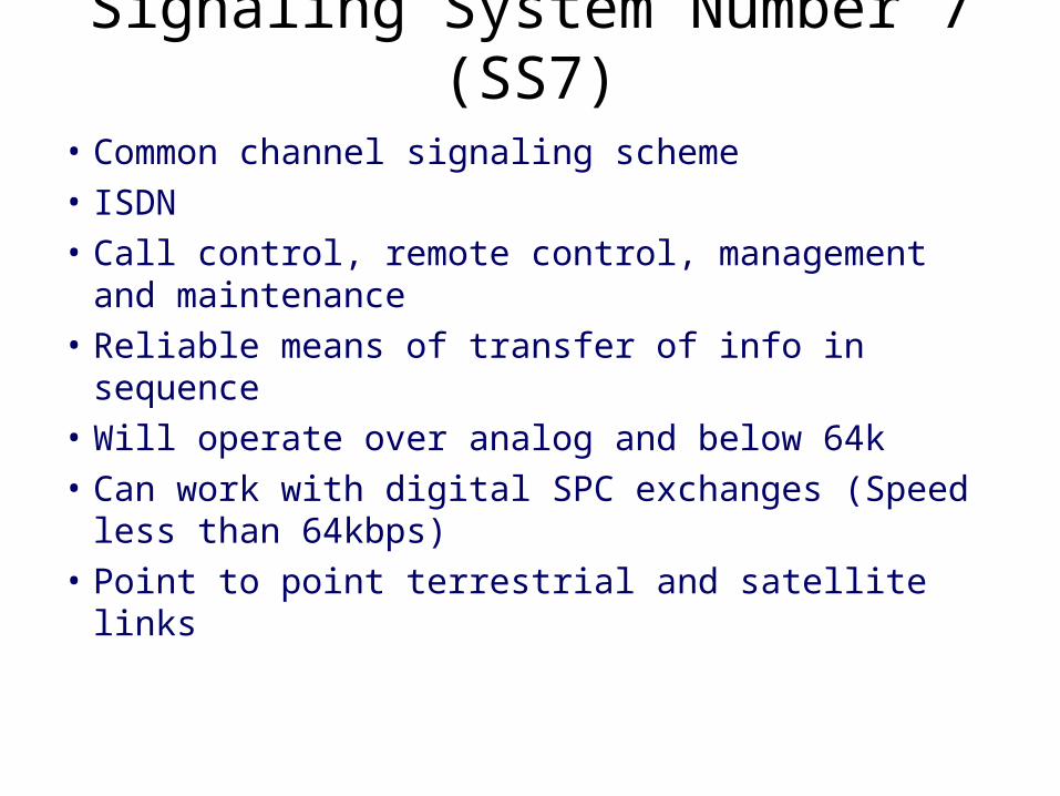
Signaling System Number 7 (SS7)
• Common channel signaling scheme
• ISDN
• Call control, remote control, management and maintenance
• Reliable means of transfer of info in sequence
• Will operate over analog and below 64k
• Can work with digital SPC exchanges (Speed less than 64kbps)
• Point to point terrestrial and satellite links
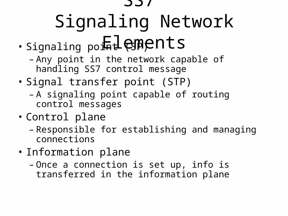
SS7 Signaling Network Elements
• Signaling point (SP)– Any point in the network capable of handling SS7
control message
• Signal transfer point (STP)– A signaling point capable of routing control messages
• Control plane– Responsible for establishing and managing
connections
• Information plane– Once a connection is set up, info is transferred in the
information plane
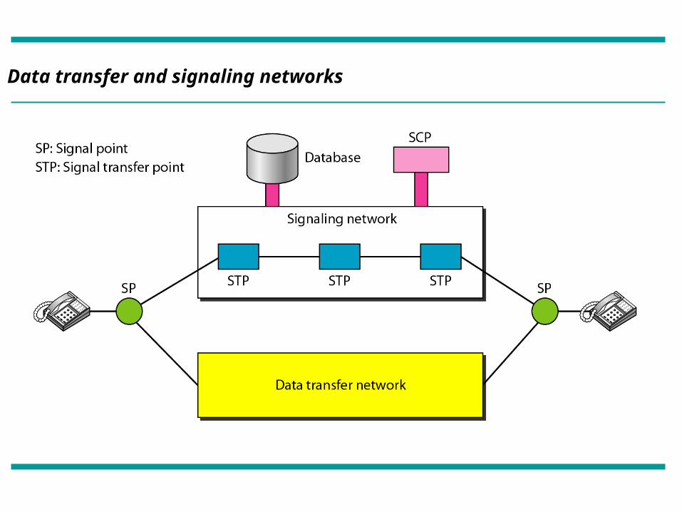
Data transfer and signaling networks
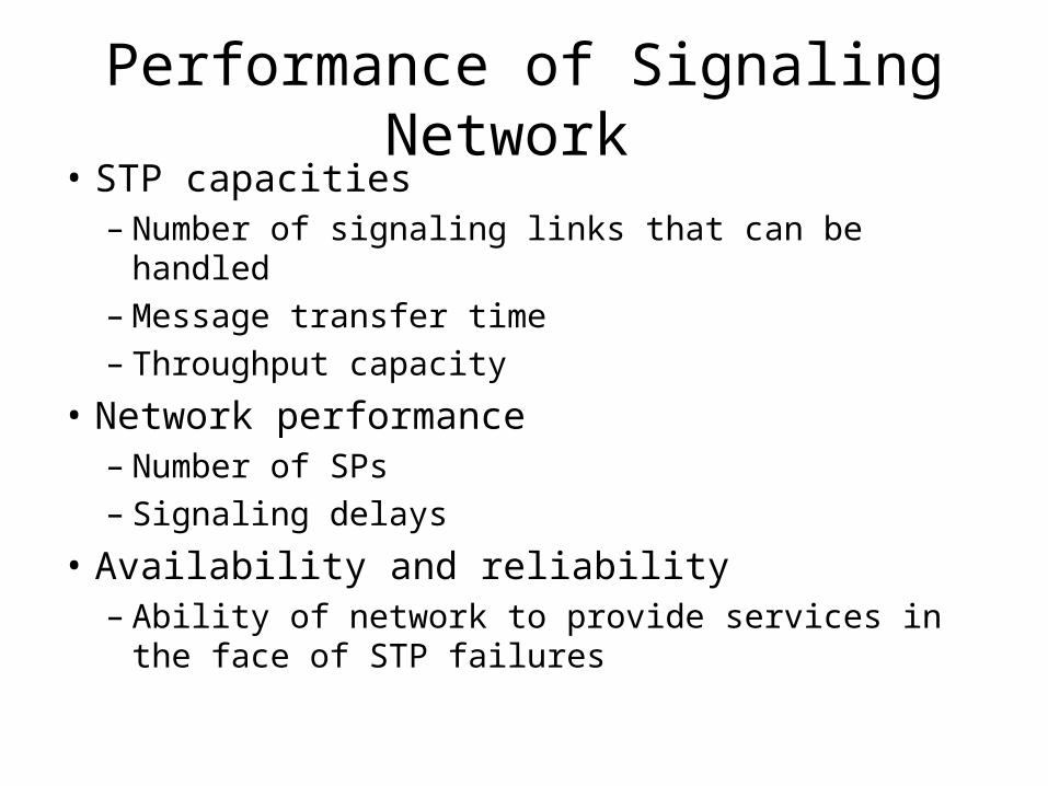
Performance of Signaling Network • STP capacities
– Number of signaling links that can be handled– Message transfer time– Throughput capacity
• Network performance– Number of SPs– Signaling delays
• Availability and reliability– Ability of network to provide services in the face of
STP failures
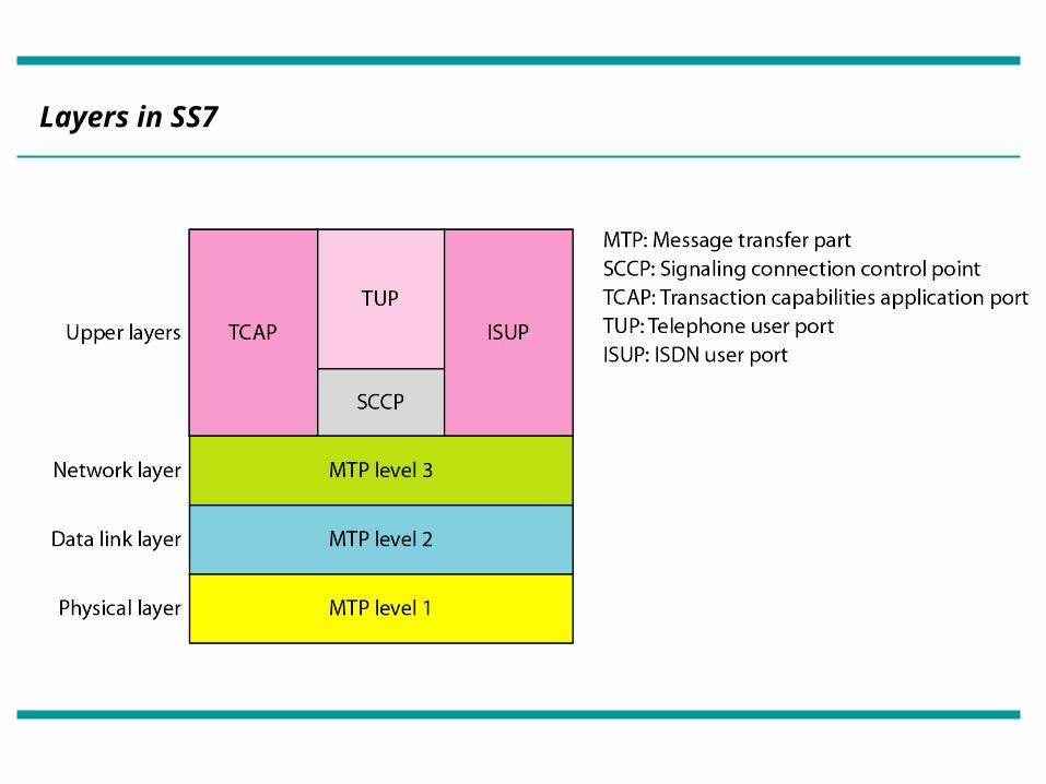
Layers in SS7
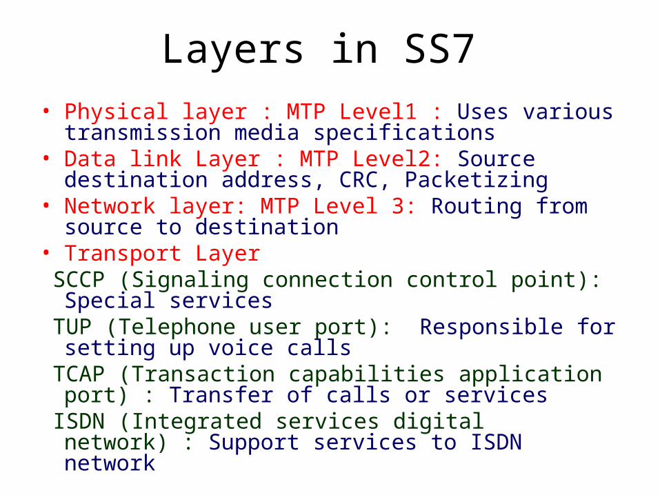
Layers in SS7 • Physical layer : MTP Level1 : Uses various transmission
media specifications• Data link Layer : MTP Level2: Source destination
address, CRC, Packetizing• Network layer: MTP Level 3: Routing from source to
destination• Transport Layer SCCP (Signaling connection control point): Special
services TUP (Telephone user port): Responsible for setting up
voice calls TCAP (Transaction capabilities application port) : Transfer
of calls or services ISDN (Integrated services digital network) : Support
services to ISDN network
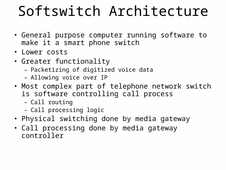
Softswitch Architecture
• General purpose computer running software to make it a smart phone switch
• Lower costs• Greater functionality
– Packetizing of digitized voice data– Allowing voice over IP
• Most complex part of telephone network switch is software controlling call process– Call routing– Call processing logic
• Physical switching done by media gateway• Call processing done by media gateway controller
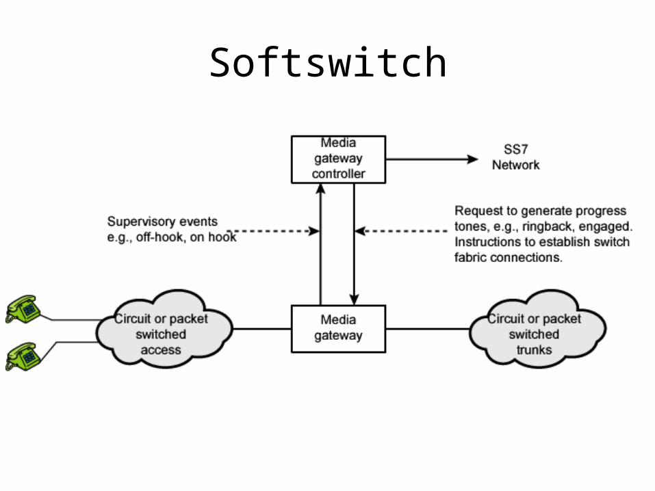
Softswitch