Embed Size (px)
Citation preview

Tele Radio TigerBASIC INSTRUCTIONSFOR 10-BUTTONS TRANSMITTER
IM-TG-TX010-A04-EN
ARTICLE CODE: RX1-A, RX2-A, RX3-A, TX1-A, TG-R1-1-0000, TG-R1-11-0000, TG-R1-6-0000, TG-T3-4-0000
INSTALL, START, TURN OFF, LOG IN, LOG OUT, REGISTER, ERASE, TROUBLE SHOOTING. EXCEPTIONAL SITUATIONS
ENGLISH (ORIGINAL)
Thank you for puchasing a Tele Radio product RX1-A, RX2-A, RX3-A + TX1-A
READ ALL INSTRUCTIONS CAREFULLY BEFORE MOUNTING, INSTALLING AND CONFIGURATING THE PRODUCT.
These instructions are published by Tele Radio AB without any guarantee. These instructions are solely directed towards qualified installers. The information shall not be handed to end users. The instructions may be removed or revised by Tele radio AB at any time and without any further notice. Corrections and additions will be added to the updated versions of the instructions.
The instructions that contain information on the installation and configuration of the remote radio control unit on the machine are not intended to be passed on to the end user. Only such information may be passed on to the end user, that is needed to operate the machine correctly by radio remote control. A separate end user instruction can be downloaded from our website.
Tele Radio AB products are covered by a guarantee against material, construction or manufacturing faults. During the guarantee period, Tele Radio AB may replace the product or faulty parts with new. Work under guarantee must be carried out by Tele Radio AB or by an authorized service centre specified by Tele Radio AB. Make sure that repairs and maintenance are only carried out by qualified personnel. Use only spare parts from Tele Radio AB. Contact your Tele Radio representative if you want to make a complaint about a product or require other service.
The EC declaration of conformity can be downloaded from our website.
©Tele Radio AB, 2010
TELE RADIO ABDatavägen 21, SE-436 32 Askim. Sweden Tel: +46 (0)31-748 54 60 Fax: +46 (0)31-68 54 64 www.tele-radio.com. [email protected]
3
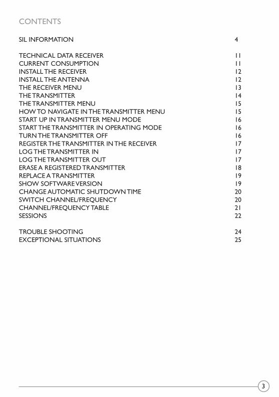
CONTENTS
SIL INFORMATION 4
TECHNICAL DATA RECEIVER 11CURRENT CONSUMPTION 11INSTALL THE RECEIVER 12INSTALL THE ANTENNA 12THE RECEIVER MENU 13THE TRANSMITTER 14THE TRANSMITTER MENU 15HOW TO NAVIGATE IN THE TRANSMITTER MENU 15START UP IN TRANSMITTER MENU MODE 16START THE TRANSMITTER IN OPERATING MODE 16TURN THE TRANSMITTER OFF 16REGISTER THE TRANSMITTER IN THE RECEIVER 17LOG THE TRANSMITTER IN 17LOG THE TRANSMITTER OUT 17ERASE A REGISTERED TRANSMITTER 18REPLACE A TRANSMITTER 19SHOW SOFTWARE VERSION 19CHANGE AUTOMATIC SHUTDOWN TIME 20SWITCH CHANNEL/FREQUENCY 20CHANNEL/FREQUENCY TABLE 21SESSIONS 22
TROUBLE SHOOTING 24EXCEPTIONAL SITUATIONS 25

4
SIL INFORMATION
SYSTEM REQUIREMENTS
The product holds two safety-related functions that comply with the requirements for SIL3 according to IEC61508:• Stopfunction: Deactivates all relays on the receiver when the STOP button on the
transmitter is pressed. • Safefunction: Activates the safe function relays on the receiver when both safe
buttons on the transmitter are pressed.
The two safety-related functions comply with the requirements for SIL3 according to IEC61508 only when they are a part of a complete end user system that complies with the requirements for SIL3 according to IEC61508.
CONNECTING AND CONTROLLING THE SAFETY FUNCTIONSThe stop function controls the stop relays from the stop button. The safe function controls the safe function relays from the two specific safe buttons. In order to comply with the require-ments for SIL3 according to IEC61508, both safety-related functions shall use their correspond-ing 2 relay outputs in an active redundant configuration in a safety-related application.
MEASURES FOR PROBABILITY OF HARDWARE FAILURES
Transmitter Stop function:Probability of dangerous failure per hour PFHd = 8.5 FITs (=λdu)Fraction of total failure rate with dangerous and detected consequence λdd = 357 FITs Diagnostic coverage DC = 98.3%Safe failure fraction SFF = 99.1 %Common cause failure 0 FITLevel of hardware fault tolerance HFT = 1Proof test interval 10 yearsDiagnostic test interval Continuous
Transmitter Safe function:Probability of dangerous failure per hour PFHd = 5.5 FITs (=λdu)Fraction of total failure rate with dangerous and detected consequence λdd = 255 FITsDiagnostic coverage DC = 98.1%Safe failure fraction SFF = 99.2 %Common cause failure 0.5 FITLevel of hardware fault tolerance HFT = 1Proof test interval 10 yearsDiagnostic test interval Continuous
5
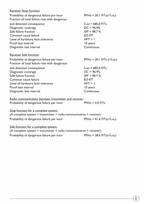
Receiver Stop function:Probability of dangerous failure per hour PFHd = 30.1 FITs(=λdu)Fraction of total failure rate with dangerous and detected consequence λdd = 685.0 FITsDiagnostic coverage DC = 96.9%Safe failure fraction SFF = 98.7 %Common cause failure 8.0 FITLevel of hardware fault tolerance HFT = 1Proof test interval 10 yearsDiagnostic test interval Continuous
Receiver Safe function:Probability of dangerous failure per hour PFHd = 30.1 FITs (=λdu)Fraction of total failure rate with dangerous and detected consequence λdd = 685.0 FITsDiagnostic coverage DC = 96.9%Safe failure fraction SFF = 98.7 %Common cause failure 8.0 FITLevel of hardware fault tolerance HFT = 1Proof test interval 10 yearsDiagnostic test interval Continuous
Radio communication between transmitter and receiver:Probability of dangerous failure per hour PFHd = 3.0 FITs
Stop function for a complete system:(A complete system = transmitter + radio communication + receiver)Probability of dangerous failure per hour PFHd = 41.6 FITs(=λdu)
Safe function for a complete system:(A complete system = transmitter + radio communication + receiver)Probability of dangerous failure per hour PFHd = 38.6 FITs(=λdu)

6
WARNING: RECEIVERS RX-1A, RX-2A, RX-3A
SR1 SR2 1 2 3 4 5 6 7 8 9 10 11 12sF1 sF2
15 16 17 18 19 20 21 22 23 24 25 26 27 28 29 30 31 32 33 34 35 36 37 38 39 40 41 42 43 44 45 46 47 48 49 50 51 52 53 54 55 56 57 58 59 60
Danger! High Voltage
SYSTEM SETUP>>Register TX
Danger! High VoltageD ! Hi h V ll
DO NOT TOUCH THE AREA MARKED WITH GREY!
7
SR1 SR2 1 2 3 4 5 6 7 8 9 10 11 12sF1 sF2
15 16 17 18 19 20 21 22 23 24 25 26 27 28 29 30 31 32 33 34 35 36 37 38 39 40 41 42 43 44 45 46 47 48 49 50 51 52 53 54 55 56 57 58 59 60
Danger! High Voltage
13
25
26
14 17 18 19 20 21 22 23 2415 16
61 62 63 64 65 66
99
67 68 69 70 71 72 73 74 75 76 77 78 79 80 81 82 83 84 85 86 87 88 89 90 91 92 93 94 95 96 97
98100
101102
103
27
28
105
104
106107108109
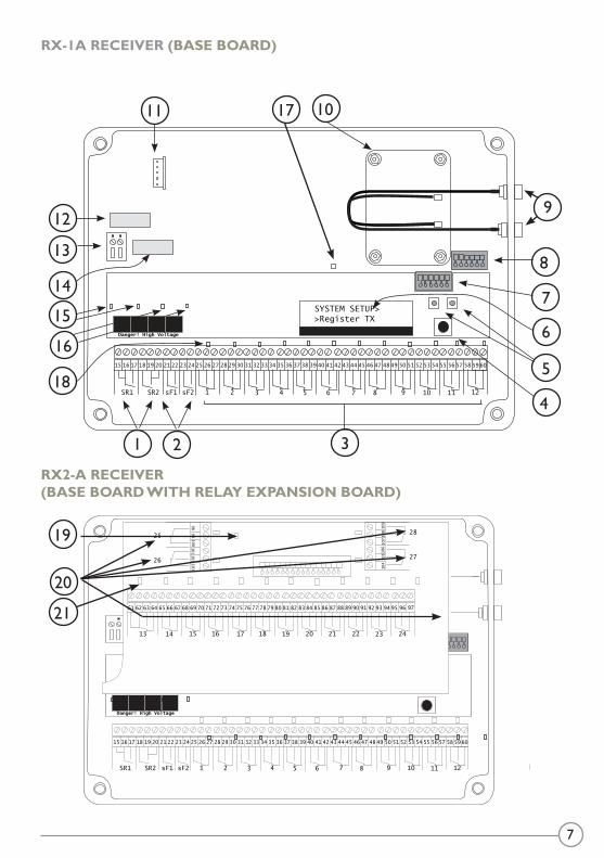
RX-1A RECEIVER (BASE BOARD)
3
4
5
6
7
8
9
21
1011
12
13
19
20
21
14
15
18
17
16
RX2-A RECEIVER (BASE BOARD WITH RELAY EXPANSION BOARD)
SR1 SR2 1 2 3 4 5 6 7 8 9 10 11 12sF1 sF2
15 16 17 18 19 20 21 22 23 24 25 26 27 28 29 30 31 32 33 34 35 36 37 38 39 40 41 42 43 44 45 46 47 48 49 50 51 52 53 54 55 56 57 58 59 60
SYSTEM SETUP>>Register TX
Danger! High Voltage
8
SR1 SR2 1 2 3 4 5 6 7 8 9 10 11 12sF1 sF2
15 16 17 18 19 20 21 22 23 24 25 26 27 28 29 30 31 32 33 34 35 36 37 38 39 40 41 42 43 44 45 46 47 48 49 50 51 52 53 54 55 56 57 58 59 60
SYSTEM SETUP>>Register TX
Danger! High Voltage
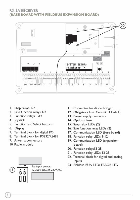
1. Stop relays 1-2 2. Safe function relays 1-23. Function relays 1-124. Joystick5. Function and Select buttons 6. Display7. Terminal block for digital I/O8. Terminal block for RS232/RS4859. Antenna connectors 10. Radio module
11. Connector for diode bridge 12. Obligatory fuse: Ceramic 3.15A(T)13. Power supply connector14. Optional fuse15. Stop relay LEDs (2)16. Safe function relay LEDs (2)17. Communication LED (base board)18. Function relay LEDs 1-1219. Communication LED (expansion board) 20. Function relays13-2821. Function relay LEDs 13-2822. Terminal block for digital and analog inputs23. Fieldbus RUN LED/ ERROR LEDFor input power:
12-350V DC, 24-230V AC.13- +
RX-3A RECEIVER (BASE BOARD WITH FIELDBUS EXPANSION BOARD)
22
9
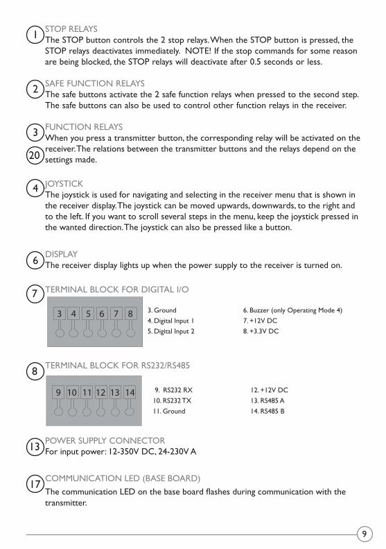
STOP RELAYSThe STOP button controls the 2 stop relays. When the STOP button is pressed, the STOP relays deactivates immediately. NOTE! If the stop commands for some reason are being blocked, the STOP relays will deactivate after 0.5 seconds or less.
SAFE FUNCTION RELAYSThe safe buttons activate the 2 safe function relays when pressed to the second step. The safe buttons can also be used to control other function relays in the receiver.
FUNCTION RELAYSWhen you press a transmitter button, the corresponding relay will be activated on the receiver. The relations between the transmitter buttons and the relays depend on the settings made.
JOYSTICKThe joystick is used for navigating and selecting in the receiver menu that is shown in the receiver display. The joystick can be moved upwards, downwards, to the right and to the left. If you want to scroll several steps in the menu, keep the joystick pressed in the wanted direction. The joystick can also be pressed like a button.
DISPLAYThe receiver display lights up when the power supply to the receiver is turned on.
TERMINAL BLOCK FOR DIGITAL I/O
TERMINAL BLOCK FOR RS232/RS485
POWER SUPPLY CONNECTORFor input power: 12-350V DC, 24-230V A
COMMUNICATION LED (BASE BOARD)The communication LED on the base board flashes during communication with the transmitter.
3. Ground 6. Buzzer (only Operating Mode 4) 4. Digital Input 1 7. +12V DC 5. Digital Input 2 8. +3.3V DC
3 4 5 6 7 8
9 10 11 12 13 14 9. RS232 RX 12. +12V DC 10. RS232 TX 13. RS485 A 11. Ground 14. RS485 B
1
2
3
20
4
7
8
6
13
17
10
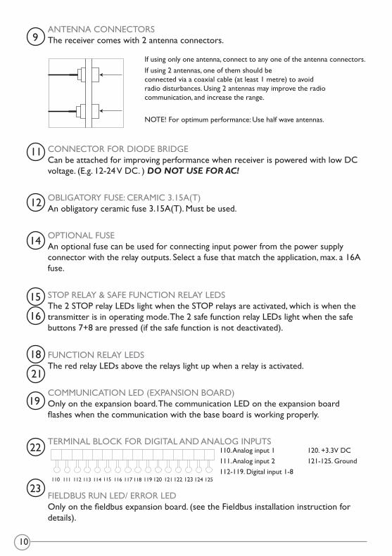
ANTENNA CONNECTORSThe receiver comes with 2 antenna connectors.
CONNECTOR FOR DIODE BRIDGE Can be attached for improving performance when receiver is powered with low DC voltage. (E.g. 12-24 V DC. ) DO NOT USE FOR AC! OBLIGATORY FUSE: CERAMIC 3.15A(T)An obligatory ceramic fuse 3.15A(T). Must be used.
OPTIONAL FUSEAn optional fuse can be used for connecting input power from the power supply connector with the relay outputs. Select a fuse that match the application, max. a 16A fuse.
STOP RELAY & SAFE FUNCTION RELAY LEDSThe 2 STOP relay LEDs light when the STOP relays are activated, which is when the transmitter is in operating mode. The 2 safe function relay LEDs light when the safe buttons 7+8 are pressed (if the safe function is not deactivated).
FUNCTION RELAY LEDSThe red relay LEDs above the relays light up when a relay is activated.
COMMUNICATION LED (EXPANSION BOARD)Only on the expansion board. The communication LED on the expansion board flashes when the communication with the base board is working properly.
TERMINAL BLOCK FOR DIGITAL AND ANALOG INPUTS
FIELDBUS RUN LED/ ERROR LEDOnly on the fieldbus expansion board. (see the Fieldbus installation instruction for details).
If using only one antenna, connect to any one of the antenna connectors. If using 2 antennas, one of them should be connected via a coaxial cable (at least 1 metre) to avoid radio disturbances. Using 2 antennas may improve the radio communication, and increase the range.
NOTE! For optimum performance: Use half wave antennas.
9
11
12
14
15
16
18
21
19
22
23110 111 112 113 114 115 116 117 118 119 120 121 122 123 124 125
110. Analog input 1111. Analog input 2112-119. Digital input 1-8
120. +3.3V DC121-125. Ground
11
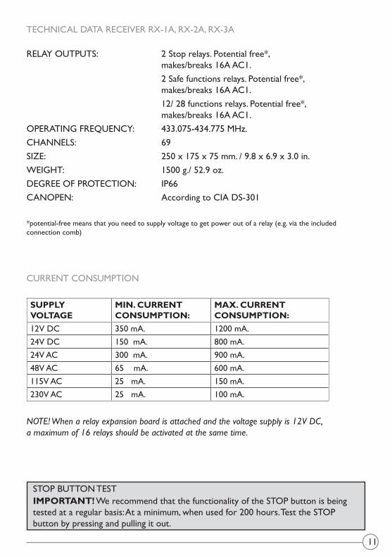
TECHNICAL DATA RECEIVER RX-1A, RX-2A, RX-3A
RELAY OUTPUTS: 2 Stop relays. Potential free*, makes/breaks 16A AC1. 2 Safe functions relays. Potential free*, makes/breaks 16A AC1. 12/ 28 functions relays. Potential free*, makes/breaks 16A AC1.OPERATING FREQUENCY: 433.075-434.775 MHz.CHANNELS: 69SIZE: 250 x 175 x 75 mm. / 9.8 x 6.9 x 3.0 in.WEIGHT: 1500 g./ 52.9 oz.DEGREE OF PROTECTION: IP66CANOPEN: According to CIA DS-301
*potential-free means that you need to supply voltage to get power out of a relay (e.g. via the included connection comb)
CURRENT CONSUMPTION
SUPPLY VOLTAGE
MIN. CURRENT CONSUMPTION:
MAX. CURRENT CONSUMPTION:
12V DC 350 mA. 1200 mA.24V DC 150 mA. 800 mA.24V AC 300 mA. 900 mA.48V AC 65 mA. 600 mA.115V AC 25 mA. 150 mA.230V AC 25 mA. 100 mA.
NOTE!Whenarelayexpansionboardisattachedandthevoltagesupplyis12VDC,amaximumof16relaysshouldbeactivatedatthesametime.
IMPORTANT! We recommend that the functionality of the STOP button is being tested at a regular basis: At a minimum, when used for 200 hours. Test the STOP button by pressing and pulling it out.
STOP BUTTON TEST

12
INSTALLATION
INSTALL THE RECEIVER
• As well away from wind, damp and water as possible.• Cable holders and vent plugs must face down to prevent water from seeping in. • If the receiver is to be placed in a a hard-to-reach place, we recommend you to
complete the settings in the receiver before mounting it.• Place receiver as high as possible off the ground.• Place receiver in as free position as possible.• Place well away from metal objects, such as metal girders, high-voltage cables and
other antennas.
INSTALL THE ANTENNA
• Check that there is a good connection between the antenna and the material on which it has been installed, e.g. after repainting of the chassis.
• Check that the antenna aerial and any coaxial cables are undamaged.• Check that the antenna is directed upwards.• The 1/2-wave antenna is ground plane independent. If the receiver is installed on a
wall, the antenna should be angled out from the wall• The 1/4-433K antenna with a 3 metres coaxial cable: For optimum range, install on a
flat roof, free from other metal objects and antennas. When installing the antenna on a vehicle, use a vehicle bracket.
• The 5/8-wave antenna with a 3 metres coaxial cable: For optimum range, install on a flat roof, free from other metal objects and antennas. When installing the antenna on a wall, use a wall bracket.
IMPORTANT! Tele Radio remote controls are often built into wider applications. We recommend that the system is provided with a wired emergency stop where necessary.
13
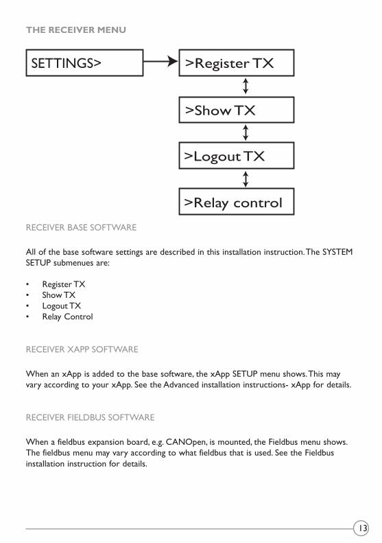
THE RECEIVER MENU
RECEIVER BASE SOFTWARE
All of the base software settings are described in this installation instruction. The SYSTEM SETUP submenues are:
• Register TX• Show TX• Logout TX• Relay Control
RECEIVER XAPP SOFTWARE
When an xApp is added to the base software, the xApp SETUP menu shows. This may vary according to your xApp. See the Advanced installation instructions- xApp for details.
RECEIVER FIELDBUS SOFTWARE
When a fieldbus expansion board, e.g. CANOpen, is mounted, the Fieldbus menu shows. The fieldbus menu may vary according to what fieldbus that is used. See the Fieldbus installation instruction for details.
>Register TX
>Show TX
SETTINGS>
>Logout TX
>Relay control

14
THE TRANSMITTER
>SETTINGS
1 2
3 4
6
8
10
5
7
9
TIGER
1
3
5
7
9
8
10
6
4
2
1.Rubber cover 7. Button 7-Safe button 13. Button 10-Start button2. Top LED 8. Button 9-Start button 14. LEDs 1-103.Display 9. Button 2 15. STOP button4.Button 1 10.Button 4 5.Button 3 11.Button 66.Button 5 12.Button 8-Safe button
1
2
3
4
5 10
11
12
13
14
15
9
6
7
8
TECHNICAL DATA
DEGREE OF PROTECTION: IP 65 OPERATING FREQUENCY: 433.075-434.775 MHz CHANNELS: 69SIZE: 200 x 70 x 35 mm./ 7.9 x 2.8 x 1.4 in.WEIGHT: 400 g./ 14.1 oz. BATTERY: 1 external, rechargeable battery (li-ion)
15
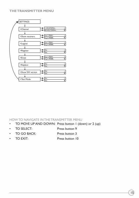
THE TRANSMITTER MENU
HOW TO NAVIGATE IN THE TRANSMITTER MENU• TO MOVE UP AND DOWN: Press button 1 (down) or 2 (up)• TO SELECT: Press button 9• TO GO BACK: Press button 3• TO EXIT: Press button 10
SETTINGS
>Channel
>Show receivers
>Logout
>Register
>Erase
>Replace
>Show SW version
>Test Mode
1: 433.075MHz...69: 434.775MHz...
NoYes
NoYes
NoYes
NoYes
E.g. 1: 92041E.g. 2: 90088...
E.g. 1: 92041E.g. 2: 90088...
E.g. 1: 92041E.g. 2: 90088...
16
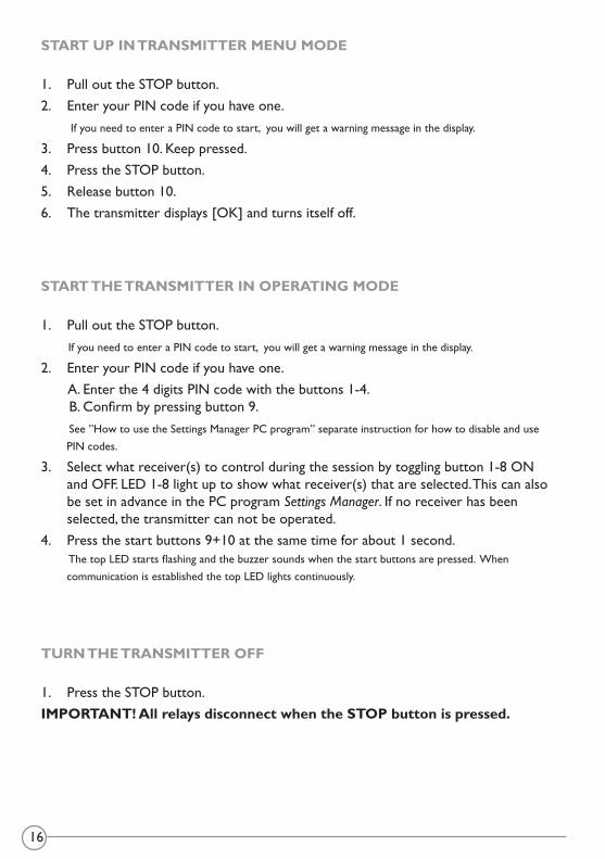
START UP IN TRANSMITTER MENU MODE
1. Pull out the STOP button.2. Enter your PIN code if you have one. If you need to enter a PIN code to start, you will get a warning message in the display.
3. Press button 10. Keep pressed. 4. Press the STOP button. 5. Release button 10. 6. The transmitter displays [OK] and turns itself off.
START THE TRANSMITTER IN OPERATING MODE
1. Pull out the STOP button. If you need to enter a PIN code to start, you will get a warning message in the display.
2. Enter your PIN code if you have one. A. Enter the 4 digits PIN code with the buttons 1-4. B. Confirm by pressing button 9. See ”How to use the Settings Manager PC program” separate instruction for how to disable and use PIN codes.
3. Select what receiver(s) to control during the session by toggling button 1-8 ON and OFF. LED 1-8 light up to show what receiver(s) that are selected. This can also be set in advance in the PC program SettingsManager. If no receiver has been selected, the transmitter can not be operated.
4. Press the start buttons 9+10 at the same time for about 1 second. The top LED starts flashing and the buzzer sounds when the start buttons are pressed. When communication is established the top LED lights continuously.
TURN THE TRANSMITTER OFF
1. Press the STOP button. IMPORTANT! All relays disconnect when the STOP button is pressed.

17
REGISTER THE TRANSMITTER IN THE RECEIVER
• 1-15 transmitters can be registered in each receiver• 1-15 receivers can be registered in each transmitter• 1-8 receivers can be operated during the session (a session is defined as the time
between starting and stopping of a transmitter).
1. Start up the receiver. 2. Select [Register TX] in the receiver menu. 3. Start up in transmitter menu mode. See ”Start up the transmitter in menu mode”.
4. Select [Register] in the transmitter menu. 5. Select [Yes]. 6. When the transmitter ID shows in the receiver display, confirm by pressing the
receiver joystick. 7. The transmitter confirms by [OK] and turns itself off. 8. Check the registration in the receiver menu, where the transmitter ID is shown at
[Show TX] and in the transmitter menu, where the receiver ID is shown at [Show receivers].
9. Write down the new settings in the Settings document (download and print from our download website).
LOG THE TRANSMITTER IN
When you have operated a receiver with a transmitter, that transmitter must be logged out from the receiver before another transmitter can be used. The new transmitter must be registered in the receiver before automatically logging on to the receiver when being started. See ”Register the transmitter in the receiver”.
LOG THE TRANSMITTER OUT
1. Start up in transmitter operating mode. See”Startthetransmitterinoperatingmode”.2. Press button 9. Keep pressed. 3. Press the STOP button. The transmitter can also be logged out from [Logout] in the transmitter menu.The transmitter displays the text [Logging out..]. If the logout fails, the transmitter displays the text [Fail].
4. The transmitter confirms by [OK] and turns itself off.

18
ERASE A REGISTERED TRANSMITTER
IMPORTANT! The recommended way to erase a transmitter from the receiver, is to do it from the transmitter menu. This way the transmitter is erased from the receiver and the receiver is erased from the transmitter.
1. Start up the transmitter in menu mode. See”Startupthetransmitterinmenumode”.2. Select [Erase]. 3. Select the receiver ID that you want to erase in the display. The transmitter displays the text [Erasing..]. If the erasing fails, the transmitter displays the text [Fail].
4. The transmitter confirms by [OK] and turns itself off. 5. Check in the receiver menu, where the transmitter ID should not show at
[Show TX] and in the transmitter menu, where the receiver ID should not show at [Show receivers].
ERASE A LOST OR BROKEN TRANSMITTER
IMPORTANT! THIS IS NOT THE RECOMMENDED WAY TO ERASE A TRANSMITTER! If a transmitter is broken or lost, it is possible to erase it from the receiver, but this way the transmitter will not know that it´s erased if found and started. The recommended way to erase a transmitter from the receiver is to do it from the transmitter menu. See“Erasearegisteredtransmitter”.
ERASE ONE OR ALL TRANSMITTERS1. Contact your representative.
19
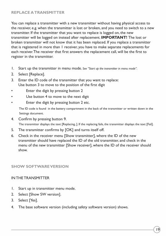
REPLACE A TRANSMITTER
You can replace a transmitter with a new transmitter without having physical access to the receiver, e.g. when the transmitter is lost or broken, and you need to switch to a new transmitter. If the transmitter that you want to replace is logged on, the new transmitter will be logged on instead after replacement. IMPORTANT! The lost or broken transmitter will not know that it has been replaced. If you replace a transmitter that is registered in more than 1 receiver, you have to make separate replacements for each receiver. The receiver that first answers the replacement call, will be the first to register in the transmitter.
1. Start up the transmitter in menu mode. See”Startupthetransmitterinmenumode”.2. Select [Replace]. 3. Enter the ID code of the transmitter that you want to replace:
Use button 3 to move to the position of the first digit• Enter the digit by pressing button 2• Use button 4 to move to the next digit• Enter the digit by pressing button 2 etc. The ID code is found in the battery compartment in the back of the transmitter or written down in the Settings document.
4. Confirm by pressing button 9. The transmitter displays the text [Replacing..]. If the replacing fails, the transmitter displays the text [Fail].
5. The transmitter confirms by [OK] and turns itself off. 6. Check in the receiver menu [Show transmitter], where the ID of the new
transmitter should have replaced the ID of the old transmitter, and check in the menu of the new transmitter [Show receiver], where the ID of the receiver should show.
SHOW SOFTWARE VERSION
IN THE TRANSMITTER
1. Start up in transmitter menu mode. 2. Select [Show SW version].3. Select [Yes].
4. The base software version (including safety software version) shows.

20
CHANGE AUTOMATIC SHUTDOWN TIME
The factory default setting for automatic shutdown is 6 minutes.
1. Start up the transmitter in menu mode. See”Startupthetransmitterinmenumode”.2. Select [Auto shutdown]. Scroll to:
• 6 min• 2 min• Off• 12 min
3. Select by pressing button 9.4. The automatic shutdown time is now changed. 5. Write down the new settings in the Settings document.
(Download and print from our download website).
SWITCH CHANNEL/FREQUENCY
The transmitters are pre-programmed to transmit at various frequencies. You only have to switch channel/ frequency in the transmitter. The receiver detects and uses the same frequency as the transmitter.
1. Start up the transmitter in menu mode. See”Startupthetransmitterinmenumode”.2. Select [Channel]. 3. Scroll up with button 1 and down with button 2 to find a channel/frequency. The transmitter displays the text [Erasing..]. If the erasing fails. the transmitter displays the text [Fail].
4. Select by pressing button 9.5. The channel is now changed and the receiver will find the same frequency.6. Write down the new settings in the Settings document.
(Download and print from our download website).
21
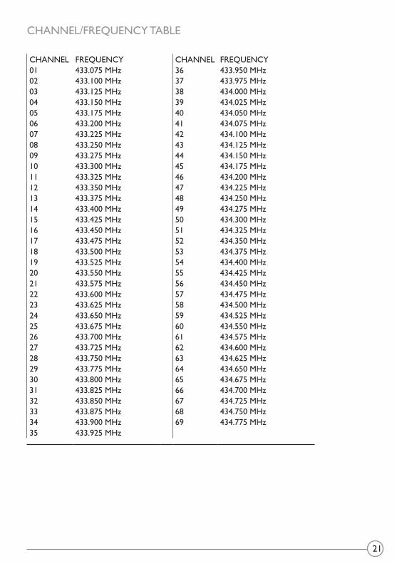
CHANNEL/FREQUENCY TABLE
CHANNEL FREQUENCY CHANNEL FREQUENCY01 433.075 MHz 36 433.950 MHz02 433.100 MHz 37 433.975 MHz03 433.125 MHz 38 434.000 MHz04 433.150 MHz 39 434.025 MHz05 433.175 MHz 40 434.050 MHz06 433.200 MHz 41 434.075 MHz07 433.225 MHz 42 434.100 MHz08 433.250 MHz 43 434.125 MHz09 433.275 MHz 44 434.150 MHz10 433.300 MHz 45 434.175 MHz11 433.325 MHz 46 434.200 MHz12 433.350 MHz 47 434.225 MHz13 433.375 MHz 48 434.250 MHz14 433.400 MHz 49 434.275 MHz15 433.425 MHz 50 434.300 MHz16 433.450 MHz 51 434.325 MHz17 433.475 MHz 52 434.350 MHz18 433.500 MHz 53 434.375 MHz19 433.525 MHz 54 434.400 MHz20 433.550 MHz 55 434.425 MHz21 433.575 MHz 56 434.450 MHz22 433.600 MHz 57 434.475 MHz23 433.625 MHz 58 434.500 MHz24 433.650 MHz 59 434.525 MHz25 433.675 MHz 60 434.550 MHz26 433.700 MHz 61 434.575 MHz27 433.725 MHz 62 434.600 MHz28 433.750 MHz 63 434.625 MHz29 433.775 MHz 64 434.650 MHz30 433.800 MHz 65 434.675 MHz31 433.825 MHz 66 434.700 MHz32 433.850 MHz 67 434.725 MHz33 433.875 MHz 68 434.750 MHz34 433.900 MHz 69 434.775 MHz35 433.925 MHz
22
SESSIONS
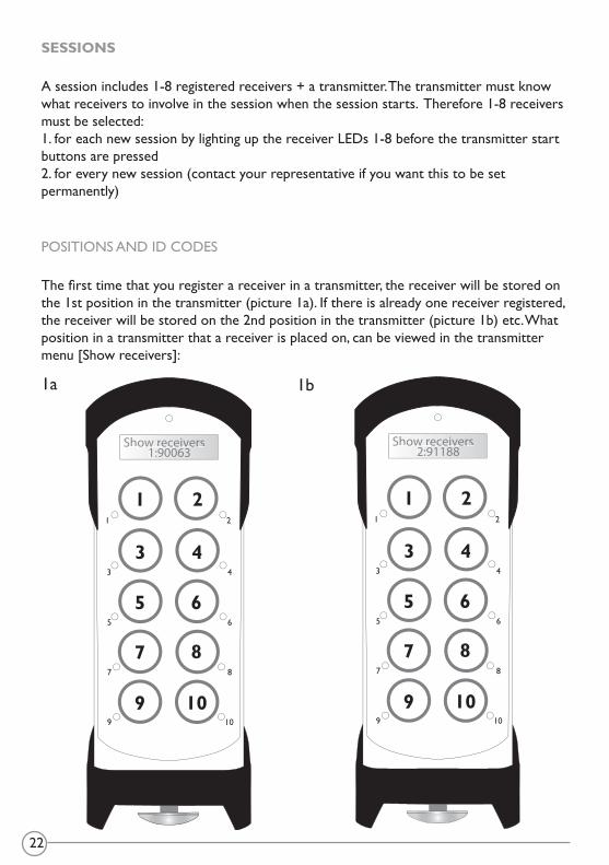
A session includes 1-8 registered receivers + a transmitter. The transmitter must know what receivers to involve in the session when the session starts. Therefore 1-8 receivers must be selected:1. for each new session by lighting up the receiver LEDs 1-8 before the transmitter start buttons are pressed2. for every new session (contact your representative if you want this to be set permanently)
POSITIONS AND ID CODES
The first time that you register a receiver in a transmitter, the receiver will be stored on the 1st position in the transmitter (picture 1a). If there is already one receiver registered, the receiver will be stored on the 2nd position in the transmitter (picture 1b) etc. What position in a transmitter that a receiver is placed on, can be viewed in the transmitter menu [Show receivers]:
Show rreceivers1:990063
1 2
3 4
6
8
10
5
7
9
1
3
5
7
9
8
10
6
4
2
Show rreceivers2:991188
1 2
3 4
6
8
10
5
7
9
1
3
5
7
9
8
10
6
4
2
1a 1b

23
The first time that you register a transmitter in a receiver, the transmitter will be stored on the 1st position in the receiver. If there is already one transmitter registered, the transmitter will be stored on the 2nd position in the receiver, etc. What position in a receiver that a transmitter is placed on, can be viewed in the receiver menu [Show TX]:
SELECT RECEIVERS FOR A SESSION
To activate receivers for a session, you need to know the position of the receiver in the transmitter.
1. Look up the receiver ID code on the label on the receiver2. Enter the transmitter menu [Show receivers]3. Check on what position the receiver(s) is placed4. Exit the menu by pressing button 105. Pull out the STOP button6. Press the corresponding button(s) (position 1= button 1, position 2= button 2, etc.)
on the transmitter7. The corresponding transmitter LED(s) lights up 8. Press the start buttons 9+10 to start the session9. The selected receiver(s) may now be synchronously operated
SR1 SR2 1 2 3 4 5 6 7 8 9 10 11 12sF1 sF2
15 16 17 18 19 20 21 22 23 24 25 26 27 28 29 30 31 32 33 34 35 36 37 38 39 40 41 42 43 44 45 46 47 48 49 50 51 52 53 54 55 56 57 58 59 60
Show TX1: 90024:1
Danger! High Voltage
*
a posição do transmissor no receptor
Exemplo:1:90024:1
código ID do transmissor a posição do receptor no transmissor

24
TROUBLE SHOOTINGWhat is your problem What might have caused it What to do
The display in the receiver is not lit.
Incorrect operating voltage into the receiver.
Check the operating voltage.
A fuse is blown. Check/ replace the fuse.There are no registered transmit-ters in the receiver display list [Show TX].
No transmitter has been registered in the receiver.
Register the transmitter in the receiver.
The transmitter does not start when the start buttons are pressed at the same time for approx. 1 sec. and then released.
The battery has been discharged. Charge the battery.
The hardware may be broken. Contact your representative.
Error message in display. Contact your representative. No receiver has been selected.
Restart and select a receiver before pressing the start buttons.
The range is too short. The antenna or the antenna cables are damaged or incorrectly installed.
1. Change the position of the antenna.
2. Replace the antenna cable.
Someone else may be transmitting on the same channel.
Switch channel.
25
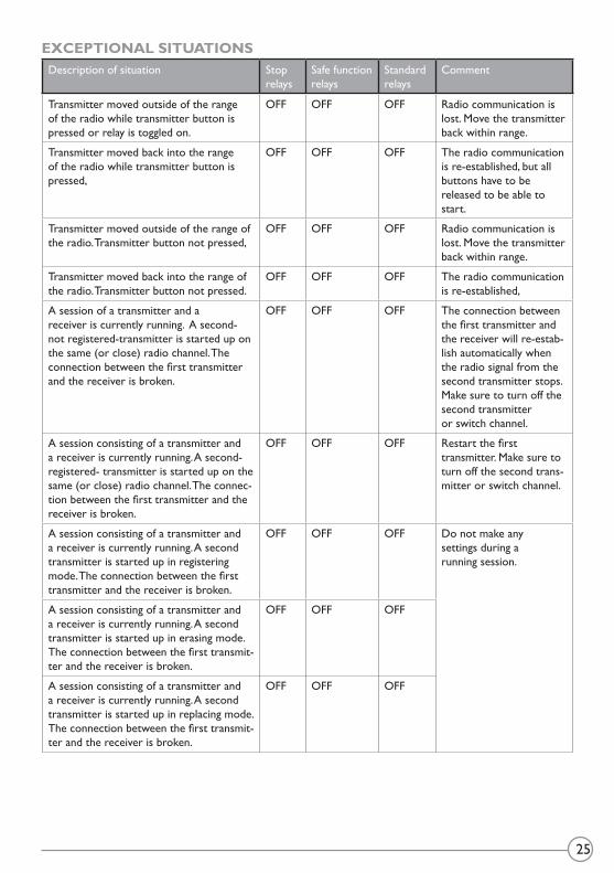
EXCEPTIONAL SITUATIONSDescription of situation Stop
relaysSafe function relays
Standard relays
Comment
Transmitter moved outside of the range of the radio while transmitter button is pressed or relay is toggled on.
OFF OFF OFF Radio communication is lost. Move the transmitter back within range.
Transmitter moved back into the range of the radio while transmitter button is pressed,
OFF OFF OFF The radio communication is re-established, but all buttons have to be released to be able to start.
Transmitter moved outside of the range of the radio. Transmitter button not pressed,
OFF OFF OFF Radio communication is lost. Move the transmitter back within range.
Transmitter moved back into the range of the radio. Transmitter button not pressed.
OFF OFF OFF The radio communication is re-established,
A session of a transmitter and a receiver is currently running. A second- not registered-transmitter is started up on the same (or close) radio channel. The connection between the first transmitter and the receiver is broken.
OFF OFF OFF The connection between the first transmitter and the receiver will re-estab-lish automatically when the radio signal from the second transmitter stops. Make sure to turn off the second transmitteror switch channel.
A session consisting of a transmitter and a receiver is currently running. A second- registered- transmitter is started up on the same (or close) radio channel. The connec-tion between the first transmitter and the receiver is broken.
OFF OFF OFF Restart the first transmitter. Make sure to turn off the second trans-mitter or switch channel.
A session consisting of a transmitter and a receiver is currently running. A second transmitter is started up in registering mode. The connection between the first transmitter and the receiver is broken.
OFF OFF OFF Do not make any settings during a running session.
A session consisting of a transmitter and a receiver is currently running. A second transmitter is started up in erasing mode. The connection between the first transmit-ter and the receiver is broken.
OFF OFF OFF
A session consisting of a transmitter and a receiver is currently running. A second transmitter is started up in replacing mode. The connection between the first transmit-ter and the receiver is broken.
OFF OFF OFF


TELE RADIO SVERIGESwedenTel. +46 (0)31-724 98 00e-mail: [email protected]
TELE RADIO GmbHGermanyTel. +49 (0)94 51-944 8 550e-mail: [email protected]
TELE RADIO ASIAChinaTel. +86-(0)592-3111168e-mail: [email protected]
TELE RADIO TURKEYTurkeyTel. +90 216 574 22 94e-mail: [email protected]
TELE RADIO LTDEnglandTel. +44 (0) 1625 509125e-mail: [email protected]
TELE RADIO ITALIAItaly Tel. +39 (0)1 75 06 23 42e-mail: [email protected]
TELE RADIO LLCNorth America & Latin AmericaTel. +1 (305) 459 0763e-mail: [email protected]
TELE RADIO BVBeneluxTel. +31-(0)70-419 41 20e-mail: [email protected]
TELE RADIO ASNorwayTel. +47-6933 4900e-mail: [email protected]
©Tele Radio AB, 2012
TELE RADIO ABDatavägen 21, SE-436 32 Askim. Sweden Tel: +46-31-748 54 60 Fax: +46-31-68 54 64 www.tele-radio.com