Embed Size (px)
Citation preview
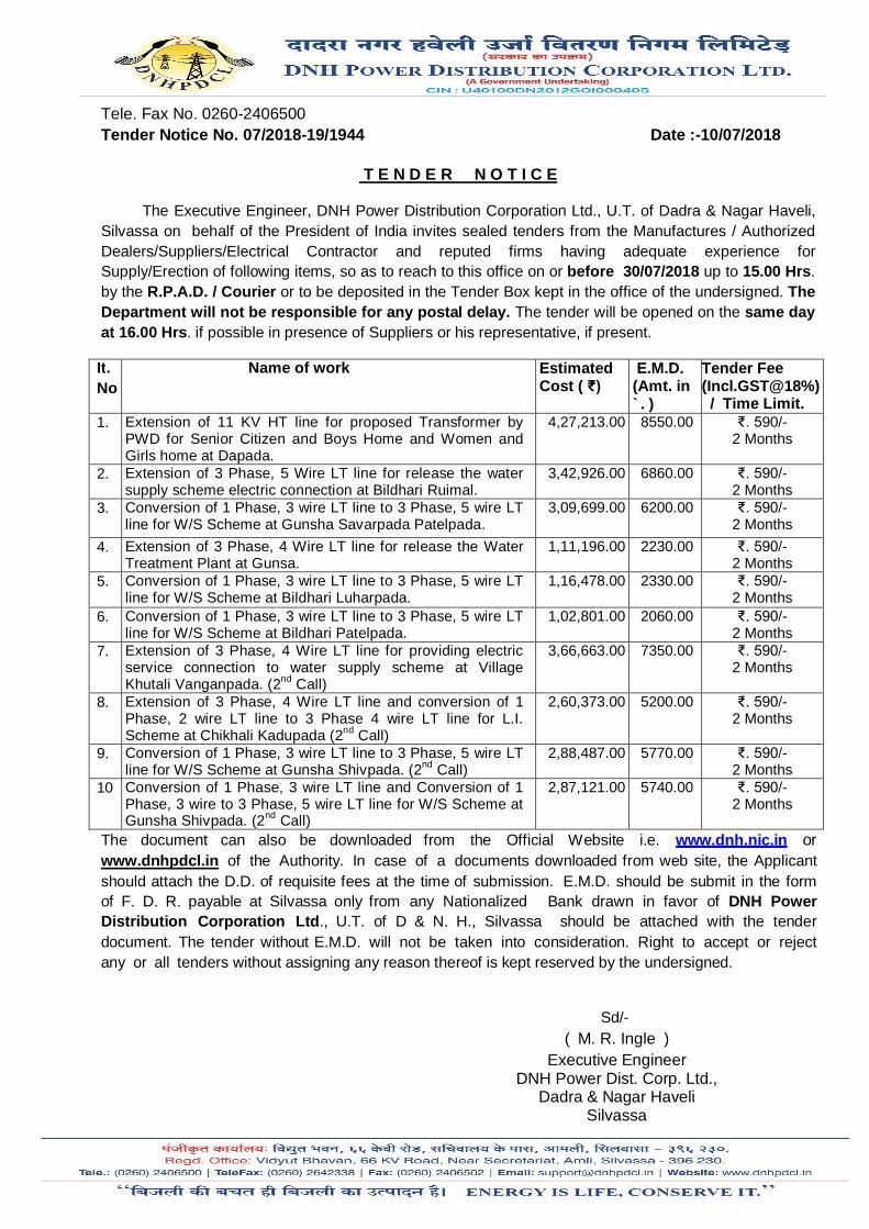
Tele. Fax No. 0260-2406500 Tender Notice No. 07/2018-19/1944 Date :-10/07/2018
T E N D E R N O T I C E
The Executive Engineer, DNH Power Distribution Corporation Ltd., U.T. of Dadra & Nagar Haveli, Silvassa on behalf of the President of India invites sealed tenders from the Manufactures / Authorized Dealers/Suppliers/Electrical Contractor and reputed firms having adequate experience for Supply/Erection of following items, so as to reach to this office on or before 30/07/2018 up to 15.00 Hrs. by the R.P.A.D. / Courier or to be deposited in the Tender Box kept in the office of the undersigned. The Department will not be responsible for any postal delay. The tender will be opened on the same day at 16.00 Hrs. if possible in presence of Suppliers or his representative, if present.
It. No
Name of work Estimated Cost ( ₹)
E.M.D. (Amt. in `. )
Tender Fee (Incl.GST@18%) / Time Limit.
1. Extension of 11 KV HT line for proposed Transformer by PWD for Senior Citizen and Boys Home and Women and Girls home at Dapada.
4,27,213.00 8550.00 ₹. 590/- 2 Months
2. Extension of 3 Phase, 5 Wire LT line for release the water supply scheme electric connection at Bildhari Ruimal.
3,42,926.00 6860.00 ₹. 590/- 2 Months
3. Conversion of 1 Phase, 3 wire LT line to 3 Phase, 5 wire LT line for W/S Scheme at Gunsha Savarpada Patelpada.
3,09,699.00 6200.00 ₹. 590/- 2 Months
4. Extension of 3 Phase, 4 Wire LT line for release the Water Treatment Plant at Gunsa.
1,11,196.00 2230.00 ₹. 590/- 2 Months
5. Conversion of 1 Phase, 3 wire LT line to 3 Phase, 5 wire LT line for W/S Scheme at Bildhari Luharpada.
1,16,478.00 2330.00 ₹. 590/- 2 Months
6. Conversion of 1 Phase, 3 wire LT line to 3 Phase, 5 wire LT line for W/S Scheme at Bildhari Patelpada.
1,02,801.00 2060.00 ₹. 590/- 2 Months
7. Extension of 3 Phase, 4 Wire LT line for providing electric service connection to water supply scheme at Village Khutali Vanganpada. (2nd Call)
3,66,663.00 7350.00 ₹. 590/- 2 Months
8. Extension of 3 Phase, 4 Wire LT line and conversion of 1 Phase, 2 wire LT line to 3 Phase 4 wire LT line for L.I. Scheme at Chikhali Kadupada (2nd Call)
2,60,373.00 5200.00 ₹. 590/- 2 Months
9. Conversion of 1 Phase, 3 wire LT line to 3 Phase, 5 wire LT line for W/S Scheme at Gunsha Shivpada. (2nd Call)
2,88,487.00 5770.00 ₹. 590/- 2 Months
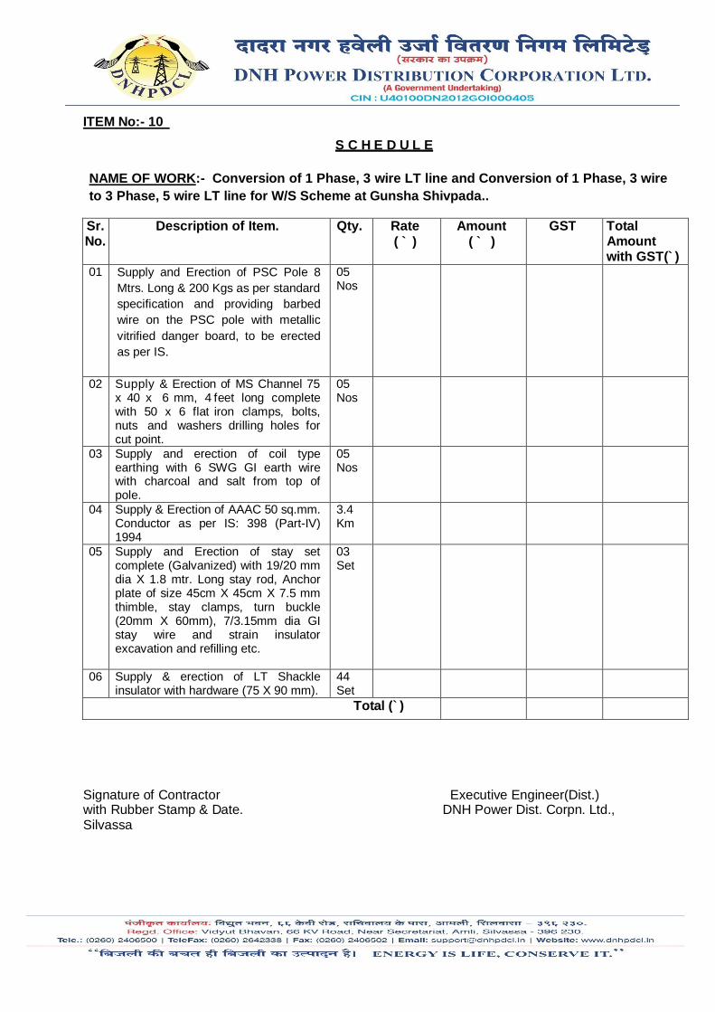
10 Conversion of 1 Phase, 3 wire LT line and Conversion of 1 Phase, 3 wire to 3 Phase, 5 wire LT line for W/S Scheme at Gunsha Shivpada. (2nd Call)
2,87,121.00 5740.00 ₹. 590/- 2 Months
The document can also be downloaded from the Official Website i.e. www.dnh.nic.in or www.dnhpdcl.in of the Authority. In case of a documents downloaded from web site, the Applicant should attach the D.D. of requisite fees at the time of submission. E.M.D. should be submit in the form of F. D. R. payable at Silvassa only from any Nationalized Bank drawn in favor of DNH Power Distribution Corporation Ltd., U.T. of D & N. H., Silvassa should be attached with the tender document. The tender without E.M.D. will not be taken into consideration. Right to accept or reject any or all tenders without assigning any reason thereof is kept reserved by the undersigned.
Sd/-
( M. R. Ingle ) Executive Engineer
DNH Power Dist. Corp. Ltd., Dadra & Nagar Haveli
Silvassa

ITEM No:- 01
S C H E D U L E NAME OF WORK:- Extension of 11 KV HT line for proposed Transformer by PWD for Senior Citizen and Boys Home and Women and Girls home at Dapada..
Sr. No.
Description of Item. Qty. Rate ( ` )
Amount ( ` )
GST Total Amt. with GST(`)
01 Supply and Erection of PSC Pole 8 Mtrs. Long & 200 Kgs as per standard specification and providing barbed wire on the PSC pole.
16 Nos
02. Supply and Erection of stay set complete (Galvanized) with 19/20 mm dia X 1.8 mtr. Long stay rod, Anchor plate of size 45cm X 45cm X 7.5 mm thimble, stay clamps, turn buckle (20mm X 60mm), 7/3.15mm dia GI stay wire and strain insulator excavation and refilling etc.
05 Set
03. Supply and Erection of " V" Cross Arm with 50 X 6 mm flate iron clamp, bolts and nuts incl. drilling
16 Nos
04. Supply and Erection of Top Fitting with bolts and Nuts, Washers.
16 Nos
05 Supply and erection of coil type earthing with 6 SWG GI earth wire with charcoal and salt from top of pole.
16 Nos
06 Supply and Erection of 11 KV H.T. Pin Insulator with Hardware.
39 Nos
08 Supply and Erection of 11 KV Disc Insulator for 11 KV over head lines with galvanized insulator fitting ball and socket type and complete with galvanised strain clamp, bolts, nuts, washers etc. as required.
18 Nos
09 Supply and Erection ACSR DOG 100 sq mm Conductor . As per Technical Specification.
2.75 Km
Total (`)
Signature of Contractor Executive Engineer(Dist.) with Rubber Stamp & Date. DNH Power Dist. Corpn. Ltd.,
Silvassa
ITEM No:- 02
S C H E D U L E
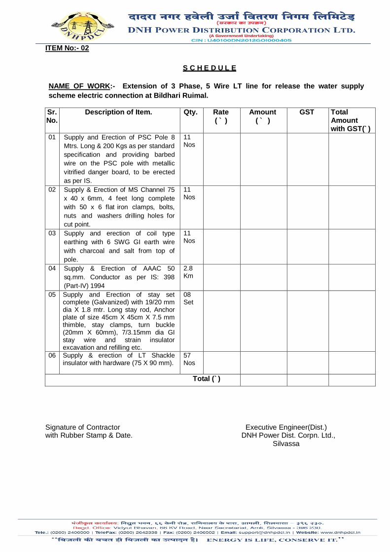
NAME OF WORK:- Extension of 3 Phase, 5 Wire LT line for release the water supply scheme electric connection at Bildhari Ruimal.
Sr. No.
Description of Item. Qty. Rate ( ` )
Amount ( ` )
GST Total Amount with GST(`)
01 Supply and Erection of PSC Pole 8 Mtrs. Long & 200 Kgs as per standard specification and providing barbed wire on the PSC pole with metallic vitrified danger board, to be erected as per IS.
11 Nos
02 Supply & Erection of MS Channel 75 x 40 x 6mm, 4 feet long complete with 50 x 6 flat iron clamps, bolts, nuts and washers drilling holes for cut point.
11 Nos
03 Supply and erection of coil type earthing with 6 SWG GI earth wire with charcoal and salt from top of pole.
11 Nos
04 Supply & Erection of AAAC 50 sq.mm. Conductor as per IS: 398 (Part-IV) 1994
2.8 Km
05 Supply and Erection of stay set complete (Galvanized) with 19/20 mm dia X 1.8 mtr. Long stay rod, Anchor plate of size 45cm X 45cm X 7.5 mm thimble, stay clamps, turn buckle (20mm X 60mm), 7/3.15mm dia GI stay wire and strain insulator excavation and refilling etc.
08 Set
06 Supply & erection of LT Shackle insulator with hardware (75 X 90 mm).
57 Nos
Total (`)
Signature of Contractor Executive Engineer(Dist.) with Rubber Stamp & Date. DNH Power Dist. Corpn. Ltd., Silvassa
ITEM No:- 03
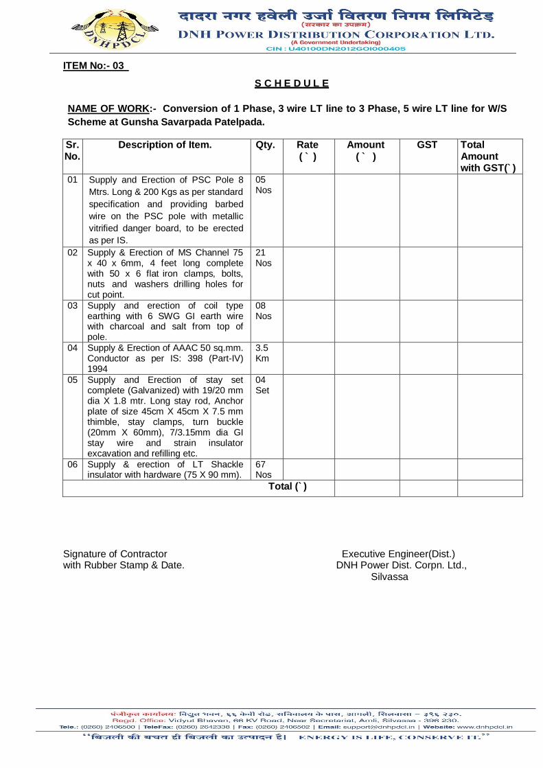
S C H E D U L E NAME OF WORK:- Conversion of 1 Phase, 3 wire LT line to 3 Phase, 5 wire LT line for W/S Scheme at Gunsha Savarpada Patelpada.
Sr. No.
Description of Item. Qty. Rate ( ` )
Amount ( ` )
GST Total Amount with GST(`)
01 Supply and Erection of PSC Pole 8 Mtrs. Long & 200 Kgs as per standard specification and providing barbed wire on the PSC pole with metallic vitrified danger board, to be erected as per IS.
05 Nos
02 Supply & Erection of MS Channel 75 x 40 x 6mm, 4 feet long complete with 50 x 6 flat iron clamps, bolts, nuts and washers drilling holes for cut point.
21 Nos
03 Supply and erection of coil type earthing with 6 SWG GI earth wire with charcoal and salt from top of pole.
08 Nos
04 Supply & Erection of AAAC 50 sq.mm. Conductor as per IS: 398 (Part-IV) 1994
3.5 Km
05 Supply and Erection of stay set complete (Galvanized) with 19/20 mm dia X 1.8 mtr. Long stay rod, Anchor plate of size 45cm X 45cm X 7.5 mm thimble, stay clamps, turn buckle (20mm X 60mm), 7/3.15mm dia GI stay wire and strain insulator excavation and refilling etc.
04 Set
06 Supply & erection of LT Shackle insulator with hardware (75 X 90 mm).
67 Nos
Total (`)
Signature of Contractor Executive Engineer(Dist.) with Rubber Stamp & Date. DNH Power Dist. Corpn. Ltd., Silvassa

ITEM No:- 04
S C H E D U L E NAME OF WORK:- Extension of 3 Phase, 4 Wire LT line for release the Water Treatment Plant at Gunsa.
Sr. No.
Description of Item. Qty. Rate ( ` )
Amount ( ` )
GST Total Amount with GST(`)
01 Supply and Erection of PSC Pole 8 Mtrs. Long & 200 Kgs as per standard specification and providing barbed wire on the PSC pole with metallic vitrified danger board, to be erected as per IS.
04 Nos
02 Supply & Erection of MS Channel 75 x 40 x 6mm, 4 feet long complete with 50 x 6 flat iron clamps, bolts, nuts and washers drilling holes for cut point.
04 Nos
03 Supply and erection of coil type earthing with 6 SWG GI earth wire with charcoal and salt from top of pole.
04 Nos
04 Supply & Erection of AAAC 50 sq.mm. Conductor as per IS: 398 (Part-IV) 1994
0.8 Km
05 Supply and Erection of stay set complete (Galvanized) with 19/20 mm dia X 1.8 mtr. Long stay rod, Anchor plate of size 45cm X 45cm X 7.5 mm thimble, stay clamps, turn buckle (20mm X 60mm), 7/3.15mm dia GI stay wire and strain insulator excavation and refilling etc.
03 Set
06 Supply & erection of LT Shackle insulator with hardware (75 X 90 mm).
18 Nos
Total (`)
Signature of Contractor Executive Engineer(Dist.) with Rubber Stamp & Date. DNH Power Dist. Corpn. Ltd., Silvassa

ITEM No:- 05
S C H E D U L E NAME OF WORK:- Conversion of 1 Phase, 3 wire LT line to 3 Phase, 5 wire LT line for W/S Scheme at Bildhari Luharpada..
Sr. No.
Description of Item. Qty. Rate ( ` )
Amount ( ` )
GST Total Amount with GST(`)
01 Supply and Erection of PSC Pole 8 Mtrs. Long & 200 Kgs as per standard specification and providing barbed wire on the PSC pole with metallic vitrified danger board, to be erected as per IS.
04 Nos
02 Supply & Erection of MS Channel 75 x 40 x 6mm, 2 feet long complete with 50 x 6 flat iron clamps, bolts, nuts and washers drilling holes for cut point.
08 Nos
03 Supply and erection of coil type earthing with 6 SWG GI earth wire with charcoal and salt from top of pole.
04 Nos
04 Supply & Erection of AAAC 50 sq.mm. Conductor as per IS: 398 (Part-IV) 1994
0.9 Km
05 Supply and Erection of stay set complete (Galvanized) with 19/20 mm dia X 1.8 mtr. Long stay rod, Anchor plate of size 45cm X 45cm X 7.5 mm thimble, stay clamps, turn buckle (20mm X 60mm), 7/3.15mm dia GI stay wire and strain insulator excavation and refilling etc.
02 Set
06 Supply & erection of LT Shackle insulator with hardware (75 X 90 mm).
28 Nos
Total (`)
Signature of Contractor Executive Engineer(Dist.) with Rubber Stamp & Date. DNH Power Dist. Corpn. Ltd., Silvassa

ITEM No:- 06
S C H E D U L E NAME OF WORK:- Conversion of 1 Phase, 3 wire LT line to 3 Phase, 5 wire LT line for W/S Scheme at Bildhari Patelpada.
Sr. No.
Description of Item. Qty. Rate ( ` )
Amount ( ` )
GST Total Amount with GST(`)
01 Supply and Erection of PSC Pole 8 Mtrs. Long & 200 Kgs as per standard specification and providing barbed wire on the PSC pole with metallic vitrified danger board, to be erected as per IS.
03 Nos
02 Supply & Erection of MS Channel 75 x 40 x 6 mm, 2 feet long complete with 50 x 6 flat iron clamps, bolts, nuts and washers drilling holes for cut point.
03 Nos
03 Supply and erection of coil type earthing with 6 SWG GI earth wire with charcoal and salt from top of pole.
03 Nos
04 Supply & Erection of AAAC 50 sq.mm. Conductor as per IS: 398 (Part-IV) 1994
0.9 Km
05 Supply and Erection of stay set complete (Galvanized) with 19/20 mm dia X 1.8 mtr. Long stay rod, Anchor plate of size 45cm X 45cm X 7.5 mm thimble, stay clamps, turn buckle (20mm X 60mm), 7/3.15mm dia GI stay wire and strain insulator excavation and refilling etc.
02 Set
06 Supply & erection of LT Shackle insulator with hardware (75 X 90 mm).
25 Nos
Total (`)
Signature of Contractor Executive Engineer(Dist.) with Rubber Stamp & Date. DNH Power Dist. Corpn. Ltd., Silvassa

ITEM No:- 07
S C H E D U L E NAME OF WORK:- Extension of 3 Phase, 4 Wire LT line for providing electric service connection to water supply scheme at Village Khutali Vanganpada.
Sr. No.
Description of Item. Qty. Rate ( ` )
Amount ( ` )
GST Total Amount with GST(`)
01 Supply and Erection of PSC Pole 8 Mtrs. Long & 200 Kgs as per standard specification and providing barbed wire on the PSC pole with metallic vitrified danger board, to be erected as per IS.
17 Nos
02 Supply and Erection of stay set complete (Galvanized) with 19/20 mm dia X 1.8 mtr. Long stay rod, Anchor plate of size 45cm X 45cm X 7.5 mm thimble, stay clamps, turn buckle (20mm X 60mm), 7/3.15mm dia GI stay wire and strain insulator excavation and refilling etc.
08 Nos
03 Supply & erection of LT Shackle insulator with hardware (75 X 90 mm).
72 Nos
04 Supply and erection of coil type earthing with 6 SWG GI earth wire with charcoal and salt from top of pole.
17 Nos
05 Supply & Erection of AAAC 50 sq.mm. Conductor as per IS: 398 (Part-IV) 1994
4.1 Km
Total (`)
Signature of Contractor Executive Engineer(Dist.) with Rubber Stamp & Date. DNH Power Dist. Corpn. Ltd., Silvassa

ITEM No:- 08
S C H E D U L E NAME OF WORK:- Extension of 3 Phase, 4 Wire LT line and conversion of 1 Phase, 2 wire LT line to 3 Phase 4 wire LT line for L.I. Scheme at Chikhali Kadupada..
Sr. No.
Description of Item. Qty. Rate ( ` )
Amount ( ` )
GST Total Amount with GST(`)
01 Supply and Erection of PSC Pole 8 Mtrs. Long & 200 Kgs as per standard specification and providing barbed wire on the PSC pole with metallic vitrified danger board, to be erected as per IS.
06 Nos
02 Supply and Erection of stay set complete (Galvanized) with 19/20 mm dia X 1.8 mtr. Long stay rod, Anchor plate of size 45cm X 45cm X 7.5 mm thimble, stay clamps, turn buckle (20mm X 60mm), 7/3.15mm dia GI stay wire and strain insulator excavation and refilling etc.
05 Set
03 Supply & Erection of MS Channel 75 x 40 x 6 mm, 2 feet long complete with 50 x 6 flat iron clamps, bolts, nuts and washers drilling holes for cut point.
26 Nos
04 Supply & erection of LT Shackle insulator with hardware (75 X 90 mm).
52 Set
05 Supply & Erection of AAAC 50 sq.mm. Conductor as per IS: 398 (Part-IV) 1994
2.85 Km
Total (`)
Signature of Contractor Executive Engineer(Dist.) with Rubber Stamp & Date. DNH Power Dist. Corpn. Ltd., Silvassa

ITEM No:- 09
S C H E D U L E NAME OF WORK:- Conversion of 1 Phase, 3 wire LT line to 3 Phase, 5 wire LT line for W/S Scheme at Gunsha Shivpada..
Sr. No.
Description of Item. Qty. Rate ( ` )
Amount ( ` )
GST Total Amount with GST(`)
01 Supply and Erection of PSC Pole 8 Mtrs. Long & 200 Kgs as per standard specification and providing barbed wire on the PSC pole with metallic vitrified danger board, to be erected as per IS.
06 Nos
02 Supply & Erection of MS Channel 75 x 40 x 6 mm, 2 feet long complete with 50 x 6 flat iron clamps, bolts, nuts and washers drilling holes for cut point.
18 Nos
03 Supply and erection of coil type earthing with 6 SWG GI earth wire with charcoal and salt from top of pole.
06 Nos
04 Supply & Erection of AAAC 50 sq.mm. Conductor as per IS: 398 (Part-IV) 1994
3.1 Km
05 Supply and Erection of stay set complete (Galvanized) with 19/20 mm dia X 1.8 mtr. Long stay rod, Anchor plate of size 45cm X 45cm X 7.5 mm thimble, stay clamps, turn buckle (20mm X 60mm), 7/3.15mm dia GI stay wire and strain insulator excavation and refilling etc.
04 Set
06 Supply & erection of LT Shackle insulator with hardware (75 X 90 mm).
38 Set
Total (`)
Signature of Contractor Executive Engineer(Dist.) with Rubber Stamp & Date. DNH Power Dist. Corpn. Ltd., Silvassa
ITEM No:- 10
S C H E D U L E NAME OF WORK:- Conversion of 1 Phase, 3 wire LT line and Conversion of 1 Phase, 3 wire to 3 Phase, 5 wire LT line for W/S Scheme at Gunsha Shivpada..
Sr. No.
Description of Item. Qty. Rate ( ` )
Amount ( ` )
GST Total Amount with GST(`)
01 Supply and Erection of PSC Pole 8 Mtrs. Long & 200 Kgs as per standard specification and providing barbed wire on the PSC pole with metallic vitrified danger board, to be erected as per IS.
05 Nos
02 Supply & Erection of MS Channel 75 x 40 x 6 mm, 4 feet long complete with 50 x 6 flat iron clamps, bolts, nuts and washers drilling holes for cut point.
05 Nos
03 Supply and erection of coil type earthing with 6 SWG GI earth wire with charcoal and salt from top of pole.
05 Nos
04 Supply & Erection of AAAC 50 sq.mm. Conductor as per IS: 398 (Part-IV) 1994
3.4 Km
05 Supply and Erection of stay set complete (Galvanized) with 19/20 mm dia X 1.8 mtr. Long stay rod, Anchor plate of size 45cm X 45cm X 7.5 mm thimble, stay clamps, turn buckle (20mm X 60mm), 7/3.15mm dia GI stay wire and strain insulator excavation and refilling etc.
03 Set
06 Supply & erection of LT Shackle insulator with hardware (75 X 90 mm).
44 Set
Total (`)
Signature of Contractor Executive Engineer(Dist.) with Rubber Stamp & Date. DNH Power Dist. Corpn. Ltd., Silvassa
Work
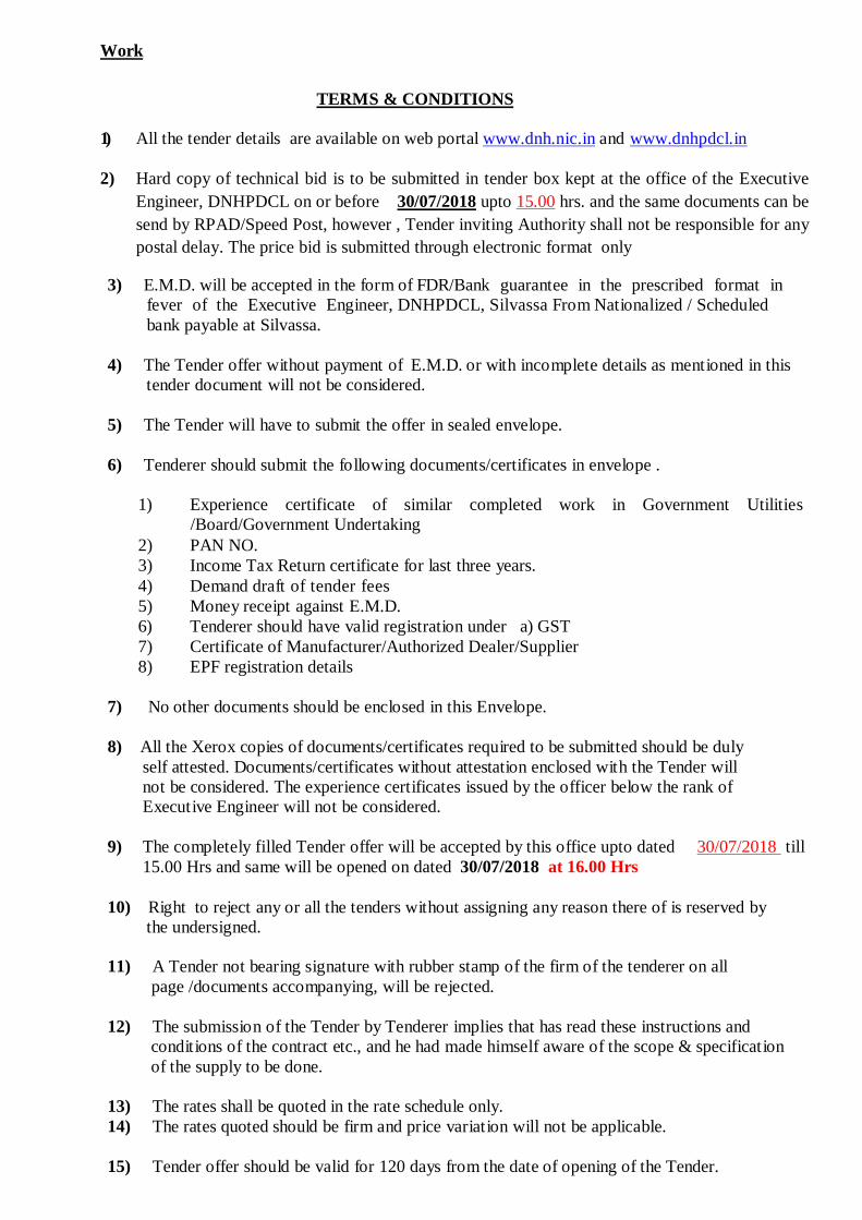
TERMS & CONDITIONS 1) All the tender details are available on web portal www.dnh.nic.in and www.dnhpdcl.in
2) Hard copy of technical bid is to be submitted in tender box kept at the office of the Executive
Engineer, DNHPDCL on or before 30/07/2018 upto 15.00 hrs. and the same documents can be send by RPAD/Speed Post, however , Tender inviting Authority shall not be responsible for any postal delay. The price bid is submitted through electronic format only
3) E.M.D. will be accepted in the form of FDR/Bank guarantee in the prescribed format in fever of the Executive Engineer, DNHPDCL, Silvassa From Nationalized / Scheduled bank payable at Silvassa.
4) The Tender offer without payment of E.M.D. or with incomplete details as mentioned in this
tender document will not be considered. 5) The Tender will have to submit the offer in sealed envelope.
6) Tenderer should submit the following documents/certificates in envelope .
1) Experience certificate of similar completed work in Government Utilities
/Board/Government Undertaking 2) PAN NO. 3) Income Tax Return certificate for last three years. 4) Demand draft of tender fees 5) Money receipt against E.M.D. 6) Tenderer should have valid registration under a) GST 7) Certificate of Manufacturer/Authorized Dealer/Supplier 8) EPF registration details
7) No other documents should be enclosed in this Envelope. 8) All the Xerox copies of documents/certificates required to be submitted should be duly
self attested. Documents/certificates without attestation enclosed with the Tender will not be considered. The experience certificates issued by the officer below the rank of Executive Engineer will not be considered.
9) The completely filled Tender offer will be accepted by this office upto dated 30/07/2018 till
15.00 Hrs and same will be opened on dated 30/07/2018 at 16.00 Hrs 10) Right to reject any or all the tenders without assigning any reason there of is reserved by
the undersigned. 11) A Tender not bearing signature with rubber stamp of the firm of the tenderer on all page /documents accompanying, will be rejected. 12) The submission of the Tender by Tenderer implies that has read these instructions and
conditions of the contract etc., and he had made himself aware of the scope & specification of the supply to be done.
13) The rates shall be quoted in the rate schedule only. 14) The rates quoted should be firm and price variation will not be applicable.
15) Tender offer should be valid for 120 days from the date of opening of the Tender.
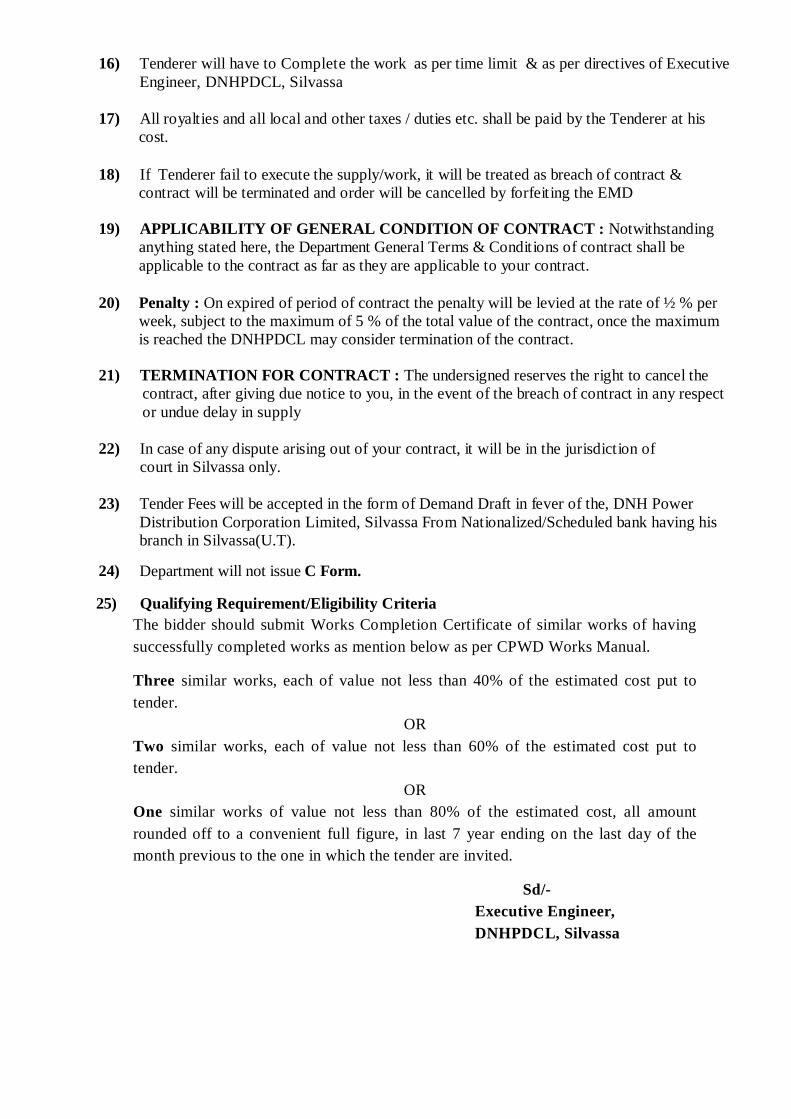
16) Tenderer will have to Complete the work as per time limit & as per directives of Executive
Engineer, DNHPDCL, Silvassa
17) All royalties and all local and other taxes / duties etc. shall be paid by the Tenderer at his cost.
18) If Tenderer fail to execute the supply/work, it will be treated as breach of contract &
contract will be terminated and order will be cancelled by forfeiting the EMD 19) APPLICABILITY OF GENERAL CONDITION OF CONTRACT : Notwithstanding
anything stated here, the Department General Terms & Conditions of contract shall be applicable to the contract as far as they are applicable to your contract.
20) Penalty : On expired of period of contract the penalty will be levied at the rate of ½ % per week, subject to the maximum of 5 % of the total value of the contract, once the maximum is reached the DNHPDCL may consider termination of the contract.
21) TERMINATION FOR CONTRACT : The undersigned reserves the right to cancel the
contract, after giving due notice to you, in the event of the breach of contract in any respect or undue delay in supply
22) In case of any dispute arising out of your contract, it will be in the jurisdiction of court in Silvassa only. 23) Tender Fees will be accepted in the form of Demand Draft in fever of the, DNH Power
Distribution Corporation Limited, Silvassa From Nationalized/Scheduled bank having his branch in Silvassa(U.T).
24) Department will not issue C Form.
25) Qualifying Requirement/Eligibility Criteria The bidder should submit Works Completion Certificate of similar works of having successfully completed works as mention below as per CPWD Works Manual.
Three similar works, each of value not less than 40% of the estimated cost put to tender.
OR Two similar works, each of value not less than 60% of the estimated cost put to tender.
OR One similar works of value not less than 80% of the estimated cost, all amount rounded off to a convenient full figure, in last 7 year ending on the last day of the month previous to the one in which the tender are invited.
Sd/- Executive Engineer, DNHPDCL, Silvassa

TECHNICAL SPECIFICATIONS FOR THE WORK TO BE CARRIED OUT
(A) Erection of Complete single Pole Structure Erection of single pole structure comprises of shifting of pole from the stacking place in the village, excavation of pit, erection in position (with base plate where required), of 8/10 meter PSC poles / 9 to 13 meter Steel Pole or any other suitable pole, fitting of clamps and cross arms and fabricated materials, fixing of caution board, anti-climbing device etc. complete as per drawing and specification inclusive of painting, numbering. Generally vertical formation will be used on each pole. However horizontal formation will have to be used in special circumstances as per instruction at Engineer in change. (B) Special Two Poles Structure Special two poles structure such as for HT line tapping, Railway crossing, any other HT/LT or telephone line crossing, terminal structure for distribution transformer center comprises of Excavation suitable pits and refilling of earth, erection in position of two Nos. of 8/10 meter PSC poles / 9 to 13 meter Steel Pole or any other suitable pole, fitting of clamps, cross arms, bracing cross arm bracing etc. as per drawing exclusive of mounting of transformer but inclusive of mounting D.O. fuses/A.B. switches/HT metering equipment etc., painting, numbering, fixing of caution Board and anti-climbing devices. The D.P. must be properly aligned and must be in plumb. Special structure if included will be erected as per drawing supplied. (C) Stringing of conductors This includes stringing of stranded and solid bare conductor with fitting of necessary HT/LT pin and strain insulators, binding on insulators, jumpering, the jointing in HT line will be done by twisting sleeve joints as per standard practice. Care must be taken in handling the conductor to protect against cuts, scratches or kinks. The conductor must not be drawn over rough or rocky ground, when it is liable to be damaged. AAAC/ACSR conductors must be drawn on wooden or aluminum pulley only. Wastage and cutting should be avoided as far as possible. Not more than 2% sag will be accepted in the materials account. The sag and spans will be maintained as per drawing and design. The cross arms insulators must be so fixed that neither tilts nor bands from position. The rate quoted should be per conductor route kilometer. The sagging should be uniform for all conductors and uneven sagging will not be allowed. The ground clearance, line to line clearances etc. to be maintained as per IE Rules 1956. Generally following span should be kept of HT line. (D) Erection of Stay Set: The erection of stay set comprises of anchor rod, turn buckle, eye bolt and excavation of suitable pit of 4' depth, fixing of stay clamp on pole, binding of GI stay wire. The stay insulators must be inserted in the stay wire on all stays as per drawing. The wrapping of the Guy wire strands at both ends the stay insulator must be even and must presents neat appearance and good workmanship. No stay should be left loose but should be tight and straight to withstand in say cyclone or sand storm, the item includes refilling of earth and painting of fabrication material. If stays are not required to be concreted, a pre casted cement concrete block will be supplied by the department from his division store which the contractor will have to transport at his own cost to the site of work and will have to use for fixing of anchor rod at site.
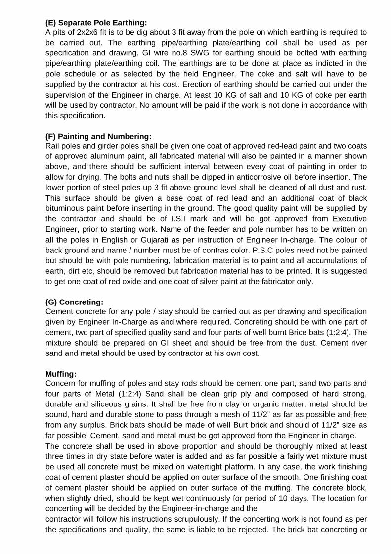
(E) Separate Pole Earthing: A pits of 2x2x6 fit is to be dig about 3 fit away from the pole on which earthing is required to be carried out. The earthing pipe/earthing plate/earthing coil shall be used as per specification and drawing. GI wire no.8 SWG for earthing should be bolted with earthing pipe/earthing plate/earthing coil. The earthings are to be done at place as indicted in the pole schedule or as selected by the field Engineer. The coke and salt will have to be supplied by the contractor at his cost. Erection of earthing should be carried out under the supervision of the Engineer in charge. At least 10 KG of salt and 10 KG of coke per earth will be used by contractor. No amount will be paid if the work is not done in accordance with this specification. (F) Painting and Numbering: Rail poles and girder poles shall be given one coat of approved red-lead paint and two coats of approved aluminum paint, all fabricated material will also be painted in a manner shown above, and there should be sufficient interval between every coat of painting in order to allow for drying. The bolts and nuts shall be dipped in anticorrosive oil before insertion. The lower portion of steel poles up 3 fit above ground level shall be cleaned of all dust and rust. This surface should be given a base coat of red lead and an additional coat of black bituminous paint before inserting in the ground. The good quality paint will be supplied by the contractor and should be of I.S.I mark and will be got approved from Executive Engineer, prior to starting work. Name of the feeder and pole number has to be written on all the poles in English or Gujarati as per instruction of Engineer In-charge. The colour of back ground and name / number must be of contras color. P.S.C poles need not be painted but should be with pole numbering, fabrication material is to paint and all accumulations of earth, dirt etc, should be removed but fabrication material has to be printed. It is suggested to get one coat of red oxide and one coat of silver paint at the fabricator only. (G) Concreting: Cement concrete for any pole / stay should be carried out as per drawing and specification given by Engineer In-Charge as and where required. Concreting should be with one part of cement, two part of specified quality sand and four parts of well burnt Brice bats (1:2:4). The mixture should be prepared on GI sheet and should be free from the dust. Cement river sand and metal should be used by contractor at his own cost. Muffing: Concern for muffing of poles and stay rods should be cement one part, sand two parts and four parts of Metal (1:2:4) Sand shall be clean grip ply and composed of hard strong, durable and siliceous grains. It shall be free from clay or organic matter, metal should be sound, hard and durable stone to pass through a mesh of 11/2” as far as possible and free from any surplus. Brick bats should be made of well Burt brick and should of 11/2” size as far possible. Cement, sand and metal must be got approved from the Engineer in charge. The concrete shall be used in above proportion and should be thoroughly mixed at least three times in dry state before water is added and as far possible a fairly wet mixture must be used all concrete must be mixed on watertight platform. In any case, the work finishing coat of cement plaster should be applied on outer surface of the smooth. One finishing coat of cement plaster should be applied on outer surface of the muffing. The concrete block, when slightly dried, should be kept wet continuously for period of 10 days. The location for concerting will be decided by the Engineer-in-charge and the contractor will follow his instructions scrupulously. If the concerting work is not found as per the specifications and quality, the same is liable to be rejected. The brick bat concreting or

cement concerting work and muffing has to be done in the presence of companies representative only and work done in his absence will be rejected and no payment made thereof. The sand, metal, brickbats shall be procured the contractor. The normal size of concreting/muffing of pole will be 5 x 2' x 2.1/2' & that for stay 2'x2'x2' muffing for pole shall be 12” dia x 2: x 9” (1” above and 1' below ground) Muffing for stay shall be 12” dia x 2:.9” (-do-) for muffing only metal is to be used and not brick bat or gravel. (H) Distribution Transformer Centre : The distribution transformer centre (200 KVA) will be of outdoor type on plinth structures as per standard drawing. This work include erection of special two pole structure and fixing of all fabricated material for support of line, L.A., HG Fuse/AB Switch, Transformer, LT Dist. Box, cable wiring, anti climbing devices etc. The works includes of transportation and hoisting of transformer, numbering and painting of all fabricated materials. Two independent separate earthing should be provided on either side of the dist. Transformer centre each consisting of one or more earth connection from lighting arrestor’s, transformer natural, transformer tank, Dist. Box etc. Signature of Contractor

TECHNICAL SPECIFICATION OF 8 MTR LONG PSC POLE & TERMS AND CONDITIONS:
[1]SCOPE OF WORK: The scope of the work covers Manufacture and supply of PSC Poles of 8 meter long and 200 Kgs. working (transverse) load in accordance with the technical terms and drawing of this specification. Alternate design / specifications shall not be considered which may be noted. [2] DIMENSIONS AND TOLERANCES: SR NO
DESCRIPTION STANDARD IN MM
MAXIMUM IN MM
MINIMUM IN MM
1 LENGTH 8000 8015 7985 2 WIDTH
- TOP - BOTTOM
114.3 336.55
117.3 339.55
111.3 333.55
3 THICKNESS 139.7 142.7 136.7 4 UP RIGHTNESS 1 TO 72 0.5 % 0.5 % 5 PLANTING
DEPTH 1381 - -
NOTE: All dimensions are in mm.
[3]WORKMANSHIP: The contractor will be responsible for the general soundness as well as good finish of each pole. The workmanship should be of high degree and poles having flaws and defects will be rejected.
[4] STANDARDS: The poles shall comply with the relevant provisions made in the following Indian standard specifications with latest amendment.
i) IS: 1678/1998 Specification for Prestressed concrete poles for
over head Power and telecommunication lines
ii) IS: 2905/1989 Method of test for concrete poles for over head Power and telecommunication lines.
iii) IS: 1343 & IS: 456 Code of practice for Prestressed and plain /
reinforced Concrete. [5] MATERIALS: The materials shall conform to this specification and be in accordance with the guaranteed particulars given. The quality of materials to be used for manufacturing of PSC poles shall be as under. [A]CEMENT: The Ordinary Portland Cement used in manufacture of prestressed concrete poles shall be relevant to IS: 8112/1989 of 43-Grade / 53- Grade to get 28 days strength of 450 Kg/ cm2.
[B] STEEL: The M.S.Bars of 6mm dia. and 4mm H.T. Steel wire used in manufacture of Prestressed concrete poles shall be conforming to IS: 2062/1989 and 6003/1983 of latest amendment thereof respectively.
[C]AGGREGATE: Aggregate used for the manufacturing of Prestressed concrete poles shall conform to IS: 383-1963. Aggregate shall consist of naturally occurring crushed black metal. They shall be hard, strong, dense, durable, clear and free
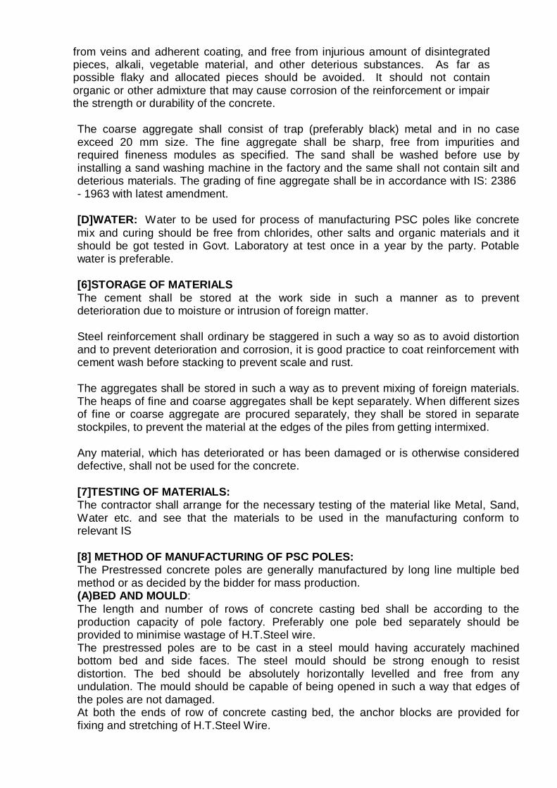
from veins and adherent coating, and free from injurious amount of disintegrated pieces, alkali, vegetable material, and other deterious substances. As far as possible flaky and allocated pieces should be avoided. It should not contain organic or other admixture that may cause corrosion of the reinforcement or impair the strength or durability of the concrete.
The coarse aggregate shall consist of trap (preferably black) metal and in no case exceed 20 mm size. The fine aggregate shall be sharp, free from impurities and required fineness modules as specified. The sand shall be washed before use by installing a sand washing machine in the factory and the same shall not contain silt and deterious materials. The grading of fine aggregate shall be in accordance with IS: 2386 - 1963 with latest amendment.
[D]WATER: Water to be used for process of manufacturing PSC poles like concrete mix and curing should be free from chlorides, other salts and organic materials and it should be got tested in Govt. Laboratory at test once in a year by the party. Potable water is preferable.
[6]STORAGE OF MATERIALS The cement shall be stored at the work side in such a manner as to prevent deterioration due to moisture or intrusion of foreign matter.
Steel reinforcement shall ordinary be staggered in such a way so as to avoid distortion and to prevent deterioration and corrosion, it is good practice to coat reinforcement with cement wash before stacking to prevent scale and rust.
The aggregates shall be stored in such a way as to prevent mixing of foreign materials. The heaps of fine and coarse aggregates shall be kept separately. When different sizes of fine or coarse aggregate are procured separately, they shall be stored in separate stockpiles, to prevent the material at the edges of the piles from getting intermixed.
Any material, which has deteriorated or has been damaged or is otherwise considered defective, shall not be used for the concrete.
[7]TESTING OF MATERIALS: The contractor shall arrange for the necessary testing of the material like Metal, Sand, Water etc. and see that the materials to be used in the manufacturing conform to relevant IS
[8] METHOD OF MANUFACTURING OF PSC POLES: The Prestressed concrete poles are generally manufactured by long line multiple bed method or as decided by the bidder for mass production. (A)BED AND MOULD: The length and number of rows of concrete casting bed shall be according to the production capacity of pole factory. Preferably one pole bed separately should be provided to minimise wastage of H.T.Steel wire. The prestressed poles are to be cast in a steel mould having accurately machined bottom bed and side faces. The steel mould should be strong enough to resist distortion. The bed should be absolutely horizontally levelled and free from any undulation. The mould should be capable of being opened in such a way that edges of the poles are not damaged. At both the ends of row of concrete casting bed, the anchor blocks are provided for fixing and stretching of H.T.Steel Wire.
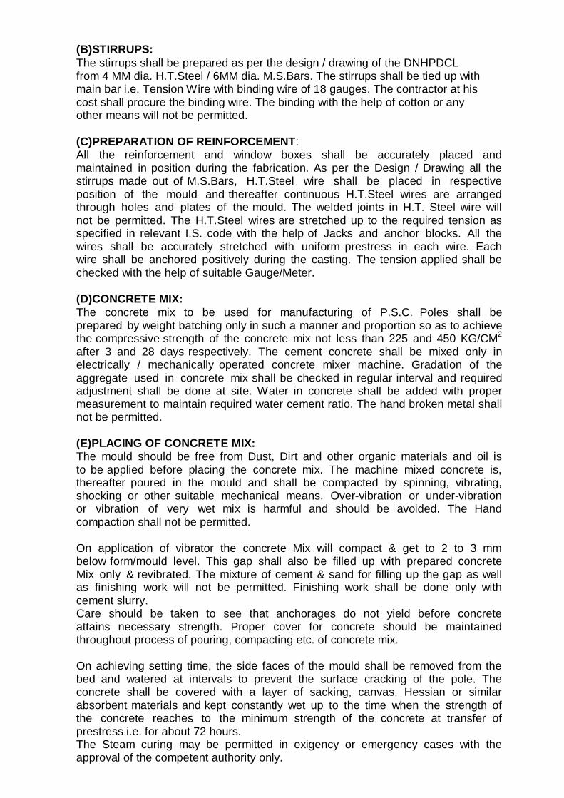
(B)STIRRUPS: The stirrups shall be prepared as per the design / drawing of the DNHPDCL from 4 MM dia. H.T.Steel / 6MM dia. M.S.Bars. The stirrups shall be tied up with main bar i.e. Tension Wire with binding wire of 18 gauges. The contractor at his cost shall procure the binding wire. The binding with the help of cotton or any other means will not be permitted.
(C)PREPARATION OF REINFORCEMENT: All the reinforcement and window boxes shall be accurately placed and maintained in position during the fabrication. As per the Design / Drawing all the stirrups made out of M.S.Bars, H.T.Steel wire shall be placed in respective position of the mould and thereafter continuous H.T.Steel wires are arranged through holes and plates of the mould. The welded joints in H.T. Steel wire will not be permitted. The H.T.Steel wires are stretched up to the required tension as specified in relevant I.S. code with the help of Jacks and anchor blocks. All the wires shall be accurately stretched with uniform prestress in each wire. Each wire shall be anchored positively during the casting. The tension applied shall be checked with the help of suitable Gauge/Meter.
(D)CONCRETE MIX: The concrete mix to be used for manufacturing of P.S.C. Poles shall be prepared by weight batching only in such a manner and proportion so as to achieve the compressive strength of the concrete mix not less than 225 and 450 KG/CM2
after 3 and 28 days respectively. The cement concrete shall be mixed only in electrically / mechanically operated concrete mixer machine. Gradation of the aggregate used in concrete mix shall be checked in regular interval and required adjustment shall be done at site. Water in concrete shall be added with proper measurement to maintain required water cement ratio. The hand broken metal shall not be permitted.
(E)PLACING OF CONCRETE MIX: The mould should be free from Dust, Dirt and other organic materials and oil is to be applied before placing the concrete mix. The machine mixed concrete is, thereafter poured in the mould and shall be compacted by spinning, vibrating, shocking or other suitable mechanical means. Over-vibration or under-vibration or vibration of very wet mix is harmful and should be avoided. The Hand compaction shall not be permitted.
On application of vibrator the concrete Mix will compact & get to 2 to 3 mm below form/mould level. This gap shall also be filled up with prepared concrete Mix only & revibrated. The mixture of cement & sand for filling up the gap as well as finishing work will not be permitted. Finishing work shall be done only with cement slurry. Care should be taken to see that anchorages do not yield before concrete attains necessary strength. Proper cover for concrete should be maintained throughout process of pouring, compacting etc. of concrete mix.
On achieving setting time, the side faces of the mould shall be removed from the bed and watered at intervals to prevent the surface cracking of the pole. The concrete shall be covered with a layer of sacking, canvas, Hessian or similar absorbent materials and kept constantly wet up to the time when the strength of the concrete reaches to the minimum strength of the concrete at transfer of prestress i.e. for about 72 hours. The Steam curing may be permitted in exigency or emergency cases with the approval of the competent authority only.

(F)DETENSIONING, CUTTING OF WIRE, AND REMOVING OF THE POLES FROM THE BED: After about 72 hours of placing the concrete, i.e. after required strength received by checking (testing) the cube test, stretched wires are released from the anchor blocks and cut with the help of welding machine. The cutting shall be started only from the centre of the bed length. The pole is then removed from the bed by lifting at 2 points using gantry and moved to the Curing Pond.
(G)CURING:
The curing of the pole shall commence after setting of the concrete curing in bed should be done for 3 days. The curing pond shall be full of water and each pole must be immersed in the water for a period of at least 28 days. If required, water sprinkling shall be done at intervals to keep the poles constantly wet as per I.S.No. 1678-1998.
(H)STORING OF POLES READY FOR INSPECTION:
The poles prepared vide method stated above shall be stacked in chronological method and a DNHPDCL indicating the date of manufacturing and number of poles be put before with particular lot so as to identify the lot by inspecting officer.
9] MARKING: The poles shall be clearly and indelibly marked with the following particulars during manufacture, at a position between 5th (W5) and 6th (W6) window indicated in the drawing so as to easily read after erection in position. The mark shall be done by pressing embossed figures / letters of 50 mm height and 20 mm width with gap of 5 mm between two figures. The sample drawing No. - C 583 - A is attached with the tender. (a) Date, month & year of manufacture,(On front face)
(b) Serial number of pole, and (On front face) (c) Maker’s serial number & mark (On front faces)
Maker’s serial number or mark on both sides of faces in oil painting to be marked before placing in curing pond. (d) DNHPDCL (in words)(above planting depth)
The pole shall also be suitably marked for the planting depth i.e. 1381 mm from bottom. On both the end of pole the anti corrosive paint i.e. epoxy based bituminous paints two coats are to be applied. One before putting in curing pond and second after removing from the pond.
[10]CUBE TESTING:
Total 6 Nos. Cubes of 100mm X 100mm X 100mm size concrete shall be cast daily and tested at release, i.e. after approx. 72 Hours of cast as well as after 28 days, in accordance with Indian Standard specification at contractor’s own expense. The mix for concrete adopted shall be such as to give cube strength not less than 225Kg/cm2 at release (after 3 days) and 450 Kg/cm2 after 28 days. Cube testing machine shall always be kept in the working condition and regular cube tests shall be taken and results be recorded in the registers duly signed by engineer-in - charge and representative of the contractor. AMPLING AND CONFORMITY
1] LOT: A. In any batch, all poles of the same class and same dimensions
shall be grouped together to constitute a LOT. B. If the number of poles in a lot exceeds 500 then the lot shall be
divided into suitable number of SUB-LOTS such that the number of

poles i.e. any sub-lot shall not exceed 500. The acceptance or otherwise of a sub lot shall be determined on the basis of the performance of sample selected from it.
2] Scale of Sampling: The number of poles to be selected from a lot or a sub-lot shall depend upon its size and shall be in accordance with col.1&2 of the table given below.
SAMPLE SIZE AND CRITERIA OF CONFORMITY
DIMENSIONAL REQUIREMENTS. Size of lot Sample Permissible NO. Of sample Poles Or Sub-Lot size No. of Defective (Out of Col.2) for
samples. Transverse Strength test (1) (2) (3) (4)
Up to 100 10 1 2 101 to 200 15 1 3 201 to 300 20 2 4 301 to 500 30 3 5
3] Number of Tests: All the poles as selected as above shall be tested for overall length, cross-section and uprightness. The number of poles to be tested for transverse strength test shall be in accordance with col. 4 of table. These poles may be selected from those already tested.
4] Criteria of conformity: A lot or sub-lot shall be considered as conforming to the specification if the conditions under are satisfied. The numbers of poles which dose not satisfy the requirements of overall length; cross-section and uprightness shall not exceed the corresponding number given in col.3 of Table. If the number of such poles exceeds the corresponding number, all poles in the lot or sub-lot shall be tested for these requirements, and those not satisfying the requirements shall be rejected. All the poles tested for transverse strength test shall satisfy the requirements of the test. If one or more poles fail, twice the number of poles originally tested shall be selected from those already selected, and subjected to the test. If there is no failure among these poles, the lot or the sub-lot shall be considered to have satisfied the requirements of this test. If one or more poles of the second samples fail, the lot or the sub-lot represented by the corresponding samples shall be considered not to have passed the test.
METHOD OF INSPECTION AND TESTING GENERAL: The tests on poles shall not be carried out earlier than 28 days from date of manufactured for poles manufactured from ordinary Portland cement or blast furnace slag cement. If a chloride free ad mixture is used or rapid hardening Cement of Grade 43 / 53 is used than pole can be tested at 14 days of age. The specimens shall be inspected and any specimen with visible flaws shall be discarded. If any test specimen fails because of mechanical reasons, such as failure of testing equipment of improper specimen preparation, it shall be discarded and another specimen shall be taken.
INSPECTION: The Tenderer shall offer Ready Made PSC Poles lot for inspection and relevant tests.

(i) For length - (ii) For Web thickness - (iii) Upright ness - 0.5 %
(01) DIMENSIONS: All the Poles shall be manufactured in accordance with the detailed dimensional drawing. The tolerance on dimension shall be limited to...
± 15 mm. - ± 5 mm.
(i.e. 72 to 1.005 / 0.995)
(02)METHOD OF TESTING: The pole shall be tested only in the horizontal position or as specified in I.S. 1678 / latest amendment & I.S. 2905 /1989 latest amendment. While testing in the horizontal position, provision shall be made by suitable supports to compensate for the overhanging weight of the pole; for this purpose the overhanging portion of the pole may be supported on a movable trolley or similar device.The frictional resistance of the supporting devices should be separately determined and deducted from the total final load applied on the pole. Theoretically the permanent deflection should be as per IS 2905 / 1966 and latest amendment thereof. The recovery of deformations should not be less than 90%.
A] Testing Arrangement - The pole shall be fixed in the crib longitudinally from butt to its ground line and then it shall be secured firmly in place. Wooden saddles with concave surfaces and other packing shall be placed around the pole to prevent injury to the butt section as specified in IS: 2905/1966 – latest amendment. To minimise vertical movement at the point of load application and to reduce the stresses due to dead weight of the pole, a rail support shall be provided near the point of load application, or alternately a number of friction less supports in the form of trolleys may be provided near the end or throughout the length of the pole. The rail support or other forms of support shall be such that any friction associated with the deflection of the pole under load shall not be a significant portion of the measured load on the pole. B] Loading - The load shall be applied at a point 600 mm from the top of the pole by means of a suitable device, such as a wire rope and winch placed in a direction normal to the direction of the length of the pole, so that the minimum length of the straight rope under pull (excluding the curved portion near the transmitting devices) is not less than two times the length of the pole. If the loading device is set sufficiently far away from the pole to make the angle between the initial and final positions of pulling line small, the error in assuming that the pull is always perpendicular to the original direction of the pole axis will be negligible. The pulling line shall be kept level between the winch position and the point where load is applied to the pole. The load shall be applied at a constant rate of 4 percent of the specified test load per minute and in accordance with procedure. C] Pulling Line: The pulling line shall be secured around the pole at the load point. Load measuring device shall be placed in a way so as to accurately measure in the tension in the pulling line. The other end of which is attached to the loading equipment (winch). D] Load Measurement: Load Cell with accuracy of 5 Kg. for measurement may be adopted. Load cell shall be calibrated before every test. The load measuring device shall be supported in such a way that the force required to pull it shall not add to the measured load on the pole and that no damage is cause to the instrument if the pole suddenly breaks under test. No pullies or any other device in between load application point and load cell will be allowed.

E] Deflections - The deflection of the pole and the load applied shall be measured simultaneously at different stages of loading to provide at least five sets of readings or as specified in I.S.2905 & latest amendment thereof. The measurement of the deflection of the load point shall be made in a direction perpendicular to the unloaded position of the pole axis. The measurement shall be made correct to the nearest 1 mm by use of datum board. A second datum line shall also be established from which the movement of the ground line if any shall be measured.
F] Procedure: Load shall be applied at a point 600mm from the top of the pole and shall be steadily and gradually increased to 250 Kgs. i.e. 50% of transverse load to observe the crack and then increase to 300 Kgs. for recording the deflection. The load shall be then reduced to zero and then increased gradually to 350 Kgs. load (equal to the deflection load plus 10 percent of the minimum ultimate transverse load), and held up for 2 minutes the load shall again reduce to Zero and successively increased by 10% of ultimate transverse load (i.e. 400 Kgs.). Thereafter the load shall be increased in steps of 25 Kgs. i.e. 5 percent of the minimum ultimate transverse load until failure occurs. Each time the load is applied, and shall be held for 2 minutes. The load applied to prestressed concrete poles at the point of failure shall be measured to the nearest five kilograms. G] RECORDING OF DATA AND MEASUREMENTS: (i) Any hair cracks appearing at a stage prior to the application of the design transverse load at first crack shall be measured using feeler gauges & shall be recorded. It should also be recorded, whether the hair cracks, if any, produced on application of the 60 percent of the minimum ultimate transverse load close up on the removal or reduction of the test load.
(ii) The load applied to the pole at the time of failure shall be measured to the nearest 5Kg. iii) A Prestressed concrete pole shall be deemed not to have passed the test if crack wider than 0.1mm appears at a stage prior to the application of the design transverse load at first crack (200 Kgs.)
(iv) The definition of failure of PSC Pole in test will be (i) permanent set more than 2.5Cm. at load of 500 Kgs. Or (ii) Deflection of more than 25 Cm. at load of 500 Kgs.
H] ULTIMATE FAILURE: The conditions existing when the pole ceases to sustain a load increment owing to either crushing of concrete or snapping of the prestressing tension or permanent stretching of the steel in any part of the pole. At least one pole shall be subjected to destruction test in the contract in presence of representative from DNHPDCL, Silvassa.
I / We confirm having read the above conditions and also accept the same without any deviations.
Seal of the Firm Signature of the Authorized Place: Representatives of the firm
Date:

(TECHNICAL BID FORMAT) TECHNICAL DATA OF PSC POLES
The Guaranteed Particulars of PSC Poles 8 Mtr. 200 Kg.
01. Working load : 200 Kg.
02. Factor of safety : 2.5
03.
Ultimate Load
: 500 Kgs.
04.
Dimensions
:
(a) Bottom Cross-Section : 336.55 x 139.7 mm. (b) Top Cross-Section : 114.3 x 139.7 mm. (c) Total height : 8000 mm. (d) Uprightness (Taper) : 1 to 72 (mm or inch).
(e) Web thickness. : 57.15 mm (2.25 inch). (f) Planting Depth : 1381 mm.
05. No. of Windows : 09 nos.
06.
No. of 20mm dia. holes. (i) On Front face : 02 nos. (100 mm apart). (ii) Side face : 06 nos. (300 mm apart).
07. Minimum requirement:
(a)
Cube Test
: 450 Kg/Cm2 (28 days). : 225 Kg/Cm2 (3 days).
(b)
Initial tension in HT Steel Wire/Pole.
:
70% of 175.00 Kg/mm2 as specified in related
I.S.Code
Date:
Place: Signature of the Authorized Representatives of the firm

TECHNICAL SPECIFICATION OF COIL EARTHING 1. SCOPE:- The specification covers design, manufacture, testing of Earthing Coils for use in earthing of the HT & LT poles.
2. GENERAL REQUIREMENTS:-
Earthing coils shall be fabricated from soft GI Wire Hot Dip Galvanized. The Hot Dip galvanized wire shall have clean surface and shall be free from paint enamel or any other poor conducting material. The coil shall be made as per REC constructions standard.
The Hot Dip galvanizing shall conform to IS: 2629/1966, 2633/1972 and 4826/1969 with latest amendments.
3. TESTS:- a) Galvanizing Tests
Minimum Mass of Zinc - On GI Wire used 280 cm/m² After Coiling-266 gm/m².
The certificate from recognized laboratory shall be submitted towards mas of zinc.
b) Dip Test Dip test shall stand 3 dips of 1 minute and one dip of ½ minute before coiling and 4 dips of 1minute after coiling as per IS: 4826/1979
c) Adhesion Test
As per ISS 4826 – 1979. 4. DIMENSIONAL REQUIREMENT:-
Nominal dia. of GI Wire -4 mm (Tolerance±2.5%) Minimum no. of turns – 115 Nos. External dia of Coil (Min) – 50 mm Length of Coil (Min) – 460 mm Free length of GI Wire at one end coil (Min.) – 2500 mm The turns should be closely bound. Weight of one finished Earthing Coils (min.) – 1.850 Kg.
Guaranteed Technical Particulars of Earthing Coil
(To be submitted along with Offer)
Sl. No. Technical Particulars Requirement Bidder’s Offer 1 Nominal diameter of the G.I. wire 4mm 2 No. of turns 115 3 External dia. of Coil 50mm 4 Length of Coil 460mm 5 Free length of GI Wire at one end coil 2500mm 6 Mass of Zinc 7 Total weight of Coil 1.850Kg. 8 Whether drawing enclosed
Seal & Signeture of the tenderer

TECHNICAL SPECIFICATION STAY SETS
1.0 SCOPE
This specification covers design, manufacture, testing and dispatch of GI Stay
Sets of 16 mm dia.
2.0 GENERAL REQUIREMENTS
2.1 16 MM Dia Stay sets (Galvanized) – LT Stay Set
This stay sets (Line Guy set) will consist of the following components:-
2.1.1. Anchor Rod with one washer and Nut
Overall length of rod should be 1800 mm to be made out of 16 mm dia GS Rod, one end threaded up to 40 mm length with a pitch of 5 threads per cm and provided with one square GS washer of size 40 X 40 x 1.6 mm and one GS hexagonal nut conforming to IS:1367:1967 & IS:1363:1967. Both waster and nut to suit threaded rod of 16 mm dia. The other end of the rod to be made into a round eye having an inner dia of 40mm with best quality welding. 2.1.2. Anchor Plate Size 200 x 200 x6 mm
To be made out of GS plate of 6 mm thickness. The anchor plate should have at its centre 18 mm dia hole. 2.1.3 Turn Buckle & Eye Bolt with 2 Nuts
To be made of 16 mm dia GS Rod having an overall length of 450mm, one end of the rod to be threaded up to 300 mm length with a pitch of 5 threads per cm and provided with two GS Hexagonal nuts of suitable size conforming to IS:1363:1967 & IS:1367:1967. The other end of rod shall be rounded into a circular eye of 40 mm inner dia with proper and good quality welding. 2.1.4. Bow with Welded Angle
To be made out of 16mm dia GS rod. The finished bow shall have an over all length of 995 mm and eight of 450 mm, the apex or top of the bow shall be bent at an angle of 10 R. The other end shall be welded with proper and good quality welding to a GS angle 180 mm long having a dimension of 50 x 50 x 6 mm. The angle shall have 3 holes of 18 mm dia each. 2.1.5 Thimble
To be made on 1.5 mm thick GS sheet into a size of 75 x 22 x 40 mm and shape as per standard shall be supplied. Average Weight of Finished 16mm Stay Sets shall be at least 7.702 KG (Minimum) (Excluding Nuts Thimbles and Washer) 8.445 Kg. (Maximum) **********************

TECHNICAL SPECIFICATION FOR ALL ALUMINIUM STRANDED
ALLOY CONDUCTORS (AAAC)
[1] SCOPE:
This specification covers details of All Aluminium Alloy Conductor (AAAC) for use on overhead lines. The sizes of the conductor cover under this specification are as under:
1 Code Name AAAC Weasel AAAC Rabbit AAAC Dog. 2 Size 7/2.5 mm 7/3.15mm 7/4.26 mm 3 area in mm2 34 mm2 55 mm2 100 mm2
[2] APPLICABLE STANDARDS:
Unless otherwise specified in the specification, the conductor shall comply with IS-398 (Part-IV)/1994 with latest amendment if any & REC Specification 33/1984 (Revised March-2000).
[3] PROPERTIES OF WIRES:
The Properties of aluminum alloy wires to be used in the construction of the stranded conductors shall be as in the following table.
TABLE - I Aluminium Alloy wires used in the construction of stranded Aluminium
alloy conductors.
Diameter in mm
Cross Sectional area of wire
(nominal dia.)
Mass
Kg/Km
Minimum breaking load after stranding
Resistance (at 20ºC) ohm
/KM Nominal Min. Max Max.
2.5 2.47 2.53 4.909 mm2 13.25 1.44 KN 6.845 3.15 3.12 3.18 7.793 mm2 21.04 2.29 KN 4.290 4.26 4.22 4.30 14.253 mm2 38.48 4.18 KN 2.345
[4] PROPERTIES OF CONDUCTORS: The properties of stranded all aluminum alloy conductors of various sizes shall be as in the following table.
TABLE- II ALL ALUMINIUM ALLOY CONDUCTORS (AAAC)
Nominal alloy area
Strands & wire dia.
Sectional Area
approx. overall
dia.
approx. mass
Calculated resistance at 20ºC (max)
Approx. breaking
load. sq. mm mm sq. mm mm Kg/KM Ohm/KM KN
34 7/2.5 34.36 7.5 94.00 0.990 10.11 55 7/3.15 54.55 9.45 149.2 0.621 16.03 100 7/4.26 99.77 12.78 272.86 0.339 29.26

[5] FREEDOM FROM DEFECTS: The wire shall be smooth and free from all imperfections like, spills, splits & scratches.
[6] MATERIAL:
The conductor shall be constructed of heat treated Aluminium Magnesium silicon alloy wires having composition appropriate to the mechanical and electrical properties specified in IS-398 (Part IV)/1994 and this specification.
[7] JOINTS IN WIRES:
There shall be no joint in any wire of a stranded conductor containing seven wires, except those made in the base rod or wire before final drawing.
[8]STRANDING:
8.1 The wires used in the construction of a stranded conductor shall before stranding
satisfy all the relevant requirements of this specification. 8.2 The lay ratio shall be minimum 10 and maximum 14.
8.3 The outer layer shall be right handed. The wires in layer shall be evenly and
closely stranded. [9] SAMPLING CRITERIA:
The sampling criteria for acceptance test shall be 10% of the number of reels or drum of the lot size in accordance with clause No. 12.1 of IS-398 (Part-IV)/1994.
[10] ACCEPTANCE TESTS:
Following acceptance tests as per IS-398 (Part-IV)/1994 with latest amendment if any shall be carried out on all samples.
(i) Measurement of lay ratio. (ii) Measurement of diameters of individual wire. (iii) Measurement of resistance of individual wire. (iv) Breaking load test of individual wire. (v) Elongation test of individual wire.
[11]GUARANTEED TECHNICAL PARTICULARS (GTP):
The Guaranteed Technical Particulars (GTP) given in the Appendix-A are generally in conformity with IS-398 (Part-IV) of 1994.
The manufacturer offering ISI certificate mark, shall be deemed to be manufacturing conductor meeting the guaranteed technical particulars given in Appendix-A.
##############
APPENDIX –A
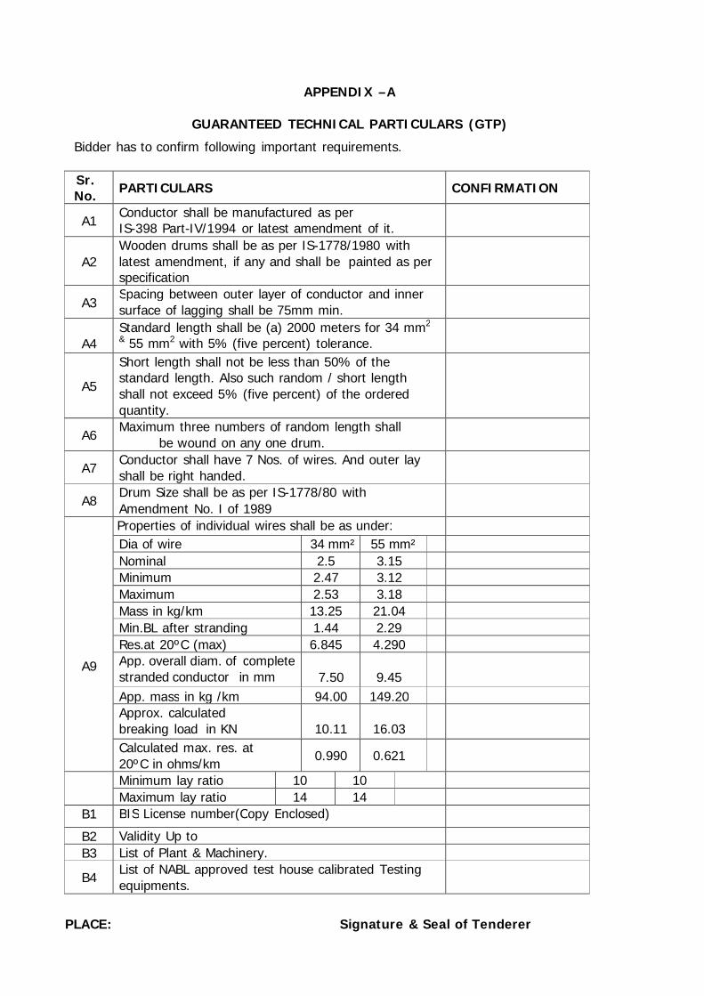
GUARANTEED TECHNICAL PARTICULARS (GTP)
Bidder has to confirm following important requirements.
Sr. No.
PARTICULARS
CONFIRMATION
A1 Conductor shall be manufactured as per IS-398 Part-IV/1994 or latest amendment of it.
A2
Wooden drums shall be as per IS-1778/1980 with latest amendment, if any and shall be painted as per specification
A3 Spacing between outer layer of conductor and inner surface of lagging shall be 75mm min.
A4
Standard length shall be (a) 2000 meters for 34 mm2 & 55 mm2 with 5% (five percent) tolerance.
A5
Short length shall not be less than 50% of the standard length. Also such random / short length shall not exceed 5% (five percent) of the ordered quantity.
A6 Maximum three numbers of random length shall be wound on any one drum.
A7 Conductor shall have 7 Nos. of wires. And outer lay shall be right handed.
A8 Drum Size shall be as per IS-1778/80 with Amendment No. I of 1989
A9
Properties of individual wires shall be as under: Dia of wire 34 mm² 55 mm² Nominal 2.5 3.15 Minimum 2.47 3.12 Maximum 2.53 3.18 Mass in kg/km 13.25 21.04 Min.BL after stranding 1.44 2.29 Res.at 20ºC (max) 6.845 4.290 App. overall diam. of complete stranded conductor in mm
7.50
9.45
App. mass in kg /km 94.00 149.20 Approx. calculated breaking load in KN
10.11
16.03
Calculated max. res. at 20ºC in ohms/km
0.990
0.621
Minimum lay ratio 10 10 Maximum lay ratio 14 14
B1 BIS License number(Copy Enclosed) B2 Validity Up to B3 List of Plant & Machinery.
B4 List of NABL approved test house calibrated Testing equipments.
PLACE: Signature & Seal of Tenderer
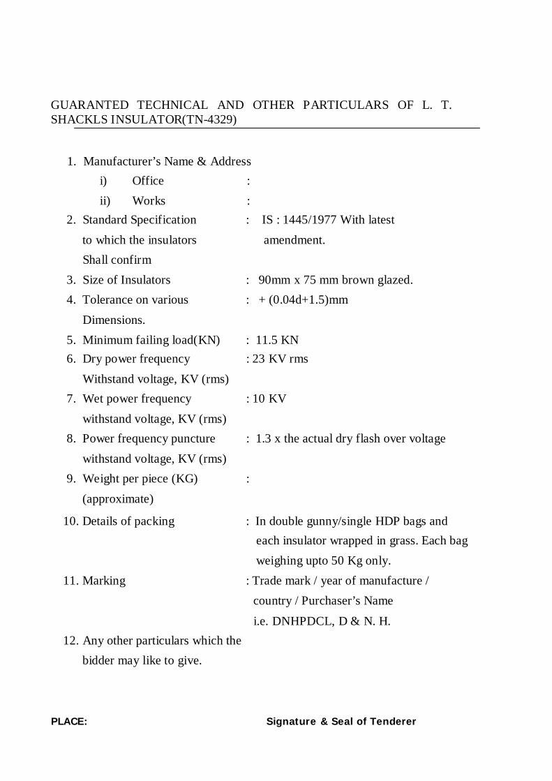
GUARANTED TECHNICAL AND OTHER PARTICULARS OF L. T. SHACKLS INSULATOR(TN-4329)
1. Manufacturer’s Name & Address
i) Office : ii) Works :
2. Standard Specification : IS : 1445/1977 With latest to which the insulators amendment. Shall confirm
3. Size of Insulators : 90mm x 75 mm brown glazed. 4. Tolerance on various : + (0.04d+1.5)mm
Dimensions.
5. Minimum failing load(KN) : 11.5 KN
6. Dry power frequency : 23 KV rms Withstand voltage, KV (rms)
7. Wet power frequency : 10 KV withstand voltage, KV (rms)
8. Power frequency puncture : 1.3 x the actual dry flash over voltage withstand voltage, KV (rms)
9. Weight per piece (KG) : (approximate)
10. Details of packing : In double gunny/single HDP bags and
each insulator wrapped in grass. Each bag weighing upto 50 Kg only.
11. Marking : Trade mark / year of manufacture /
country / Purchaser’s Name
i.e. DNHPDCL, D & N. H.
12. Any other particulars which the bidder may like to give.
PLACE: Signature & Seal of Tenderer
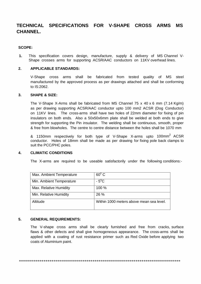
TECHNICAL SPECIFICATIONS FOR V-SHAPE CROSS ARMS MS CHANNEL. SCOPE:
1. This specification covers design, manufacture, supply & delivery of MS Channel V-Shape crosses arms for supporting ACSR/AAC conductors on 11KV overhead lines.
2. APPLICABLE STANDARDS:
V-Shape cross arms shall be fabricated from tested quality of MS steel manufactured by the approved process as per drawings attached and shall be conforming to IS:2062.
3. SHAPE & SIZE:
The V-Shape X-Arms shall be fabricated from MS Channel 75 x 40 x 6 mm (7.14 Kg/m) as per drawing supporting ACSR/AAC conductor upto 100 mm2 ACSR (Dog Conductor) on 11KV lines. The cross-arms shall have two holes of 22mm diameter for fixing of pin insulators on both ends. Also a 50x50x6mm plate shall be welded at both ends to give strength for supporting the Pin insulator. The welding shall be continuous, smooth, proper & free from blowholes. The centre to centre distance between the holes shall be 1070 mm
& 1150mm respectively for both type of V-Shape X-arms upto 100mm2 ACSR conductor. Holes of 18mm shall be made as per drawing for fixing pole back clamps to suit the PCC/PHC poles.
4. CLIMATIC CONDITIONS
The X-arms are required to be useable satisfactorily under the following conditions:-
Max. Ambient Temperature 600 C
Min. Ambient Temperature - 50C
Max. Relative Humidity 100 %
Min. Relative Humidity 26 %
Altitude Within 1000 meters above mean sea level.
5. GENERAL REQUIREMENTS:
The V-shape cross arms shall be clearly furnished and free from cracks, surface flaws & other defects and shall give homogeneous appearance. The cross-arms shall be applied with a coating of rust resistance primer such as Red Oxide before applying two coats of Aluminium paint.
*******************************************************************************

Guaranteed Technical Particulars of 11 KV Composite Pin Insulator (Polymer Type) with Hard wares. Sl. No.
Description
Unit 11kV type composite pin
insulator (Polymer 1 Type of insulator Composite polymeric pin
insulator 2 Standard according to which the insulator
manufacture & tested
IEC-61109 with upto date amendments
3 Name of materials used in manufacture of the
insulator with class/grade with class/grade
Silicon material
a)
Material of core (FRP rod i) E-glass or ECR-glass ii) Boron content
ECR glass boron content free
b) Material of housing & weather sheds
Silicon Rubber 43%
c) Material of end fitting SGI d) Sealing compound for end fittings RTV Silicon 4 Colour Grey 5 Electrical characteristics a) Normal system voltage kV (rms)
(((rms)(rms) 11 kV
b) Highest system voltage kV (rms) 12 kV c) Dry power frequency withstand voltage kV (rms) 70 kV d) Wet power frequency withstand voltage kV (rms) 50 kV e) Dry flashover voltage kV (rms) 77 kV f) Wet flashover voltage kV (rms) 55 kV g) Dry lighting impulse withstand voltage
a) Positive kV (Peak) 129 kV b) Negative kV (Peak) 135 kv
h) Dry lighting impulse flashover voltage a) Positive kV (Peak) 135 kv b) Negative kV (Peak) 141 kv
i) R/V at IMHz when energized at 10kV/30kV (rms)under condition. dry condition.
Microvolt 20(T.C Encl)
j) Creepage distance (Min) mm. 320 mm. 6 Mechanical characteristic a) Minimum failing load Kn. 05 KN 7) Dimension of insulator
i) Weight Kg. 1.350 Kg.(Approx) (approx) ii) Dia of FRP Rod mm. 21.7 mm.
iii) Length of FRP Rod mm. 200± 5mm iv) Dia of weather sheds mm. 140/110± 2 mm v) Thickness of housing mm. 3mm.
minimum vi) Dry arc distance mm. 120± 5 mm Dimensioned drawing of insulator(including
weight with tolerances in weight) enclosed Enclosed
8 Method of fixing sheds to housing (specify) single
Mould or Modular construction (injection moulding/compression moulding)
Injection Moulding
9 No. of weather sheds 3 10 Types of sheds
i) Aerodynamic Aerodynamic ii) with under ribs -----------------------------
11 Packing details Each insulator in polybag & packed in
master carton- a) Type of packing Corrugated bodies b) No. of insulator each pack One master carton box
containing 16pcs. c) Gross weight of package 17Kg (Approx) 12 Any other particulars which the bidders may like
to give It should be type tested through any
Government recognized laboratory.

Guaranteed Technical Particulars of 11 KV Disc Insulator(Boll & Socket type) (Polymer ) with Hard wares . Sl. No.
Description
Unit 11kV 45 KN type
composite Disc insulator (Polymer 1 Type of insulator Composite polymeric insulator
2 Standard according to which the insulator manufacture
& tested IEC-61109 with upto date amendments
3 Name of materials used in manufacture of the insulator
with class/grade with class/grade
Silicon material
a)
Material of core (FRP rod i) E-glass or ECR-glass
ii) Boron content
ECR glass boron content free
b) Material of housing & weather sheds
Silicon Rubber 43%
c) Material of end fitting SGI d) Sealing compound for end fittings RTV Silicon 4 Colour Grey 5 Electrical characteristics a) Normal system voltage kV (rms)
(((rms)(rms) 11 kV
b) Highest system voltage kV (rms) 12 kV c) Dry power frequency withstand voltage kV (rms) 70 kV d) Wet power frequency withstand voltage kV (rms) 50 kV e) Dry flashover voltage kV (rms) 77 kV f) Wet flashover voltage kV (rms) 55 kV g) Dry lighting impulse withstand voltage
a) Positive kV (Peak) 129 kV b) Negative kV (Peak) 135 kv
h) Dry lighting impulse flashover voltage a) Positive kV (Peak) 135 kv b) Negative kV (Peak) 141 kv
i) R/V at IMHz when energized at 10kV/30kV (rms) under condition. dry condition.
Microvolt 20(T.C Encl)
j) Creepage distance (Min) mm. 320 mm. 6 Mechanical characteristic a) Minimum failing load Kn. 45 KN 7) Dimension of insulator
i) Weight Kg. 1.250 Kg.(Approx) (approx) ii) Dia of FRP Rod mm. 16 mm.
iii) Length of FRP Rod mm. 240 mm iv) Dia of weather sheds mm. 90± 1 mm v) Thickness of housing mm. 3 mm.
minimum vi) Dry arc distance mm. 160± 5 mm Dimensioned drawing of insulator(including weight with
tolerances in weight) enclosed Enclosed
8 Method of fixing sheds to housing (specify) single Mould
or Modular construction (injection moulding/compression moulding)
Injection Moulding
9 No. of weather sheds 3 10 Types of sheds
i) Aerodynamic Aerodynamic ii) with under ribs -----------------------------
11
Packing details Each insulator in polybag & packed in wooden box
master carton- a) Type of packing Corrugated bodies b) No. of insulator each pack One master carton box containing
16pcs. c) Gross weight of package 12 Any other particulars which the bidders may like to give Brittle Fracture Pass 13 The insulator shall have “W” type phosphors Bronze
security clips for ball sockets portion of insulators confirming to IS-2486 (P-III/1974.)
Yes
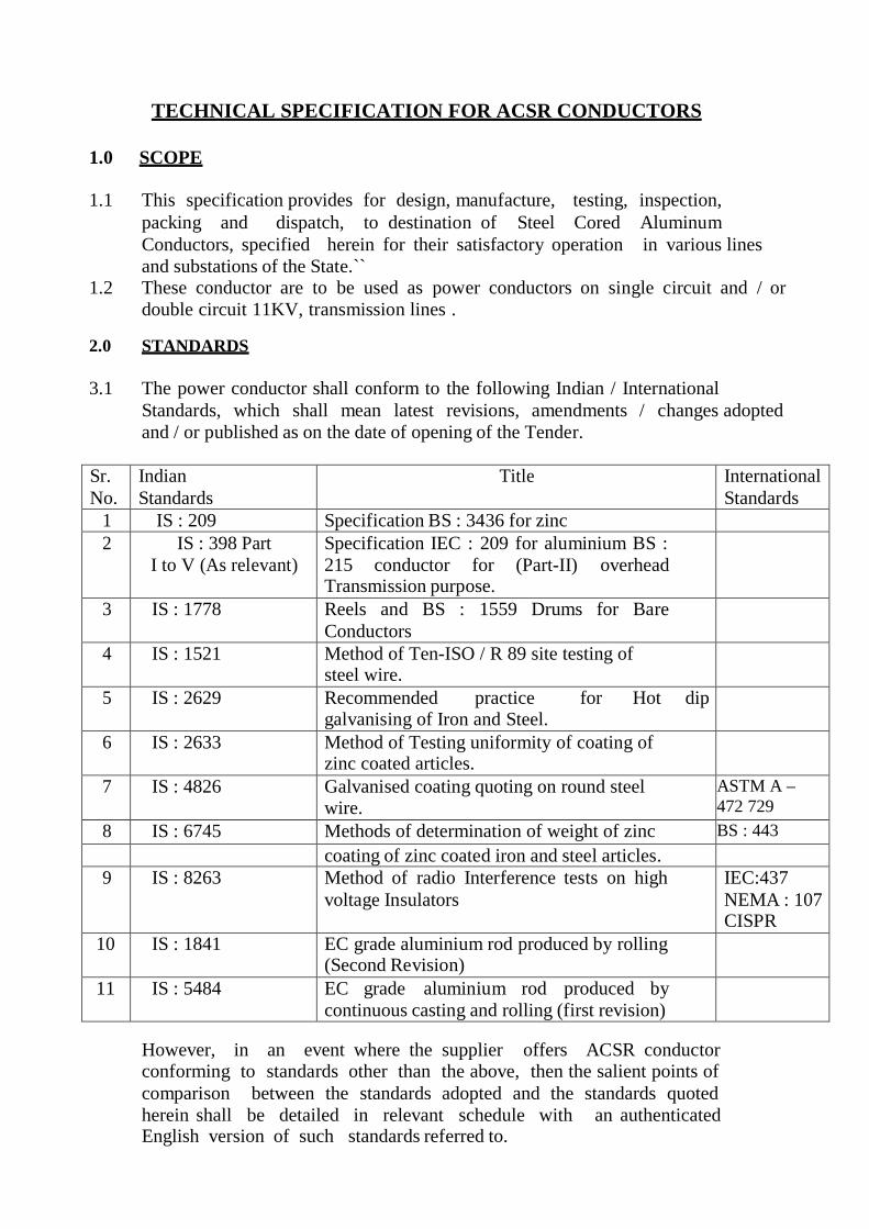
TECHNICAL SPECIFICATION FOR ACSR CONDUCTORS
1.0 SCOPE
1.1
This specification provides for design, manufacture, testing,
inspection, packing and dispatch, to destination of Steel Cored Aluminum Conductors, specified herein for their satisfactory operation in various lines and substations of the State.``
1.2 These conductor are to be used as power conductors on single circuit and / or double circuit 11KV, transmission lines .
2.0 STANDARDS
3.1 The power conductor shall conform to the following Indian / International Standards, which shall mean latest revisions, amendments / changes adopted and / or published as on the date of opening of the Tender.
Sr. No.
Indian Standards
Title International Standards
1 IS : 209 Specification BS : 3436 for zinc 2 IS : 398 Part
I to V (As relevant) Specification IEC : 209 for aluminium BS : 215 conductor for (Part-II) overhead Transmission purpose.
3 IS : 1778 Reels and BS : 1559 Drums for Bare Conductors
4 IS : 1521 Method of Ten-ISO / R 89 site testing of steel wire.
5 IS : 2629 Recommended practice for Hot dip galvanising of Iron and Steel.
6 IS : 2633 Method of Testing uniformity of coating of zinc coated articles.
7 IS : 4826 Galvanised coating quoting on round steel wire.
ASTM A – 472 729 BS : 443 8 IS : 6745 Methods of determination of weight of zinc BS : 443
coating of zinc coated iron and steel articles. 9 IS : 8263 Method of radio Interference tests on high
voltage Insulators IEC:437 NEMA : 107 CISPR
10 IS : 1841 EC grade aluminium rod produced by rolling (Second Revision)
11 IS : 5484 EC grade aluminium rod produced by continuous casting and rolling (first revision)
However, in an event where the supplier offers ACSR conductor conforming to standards other than the above, then the salient points of comparison between the standards adopted and the standards quoted herein shall be detailed in relevant schedule with an authenticated English version of such standards referred to.
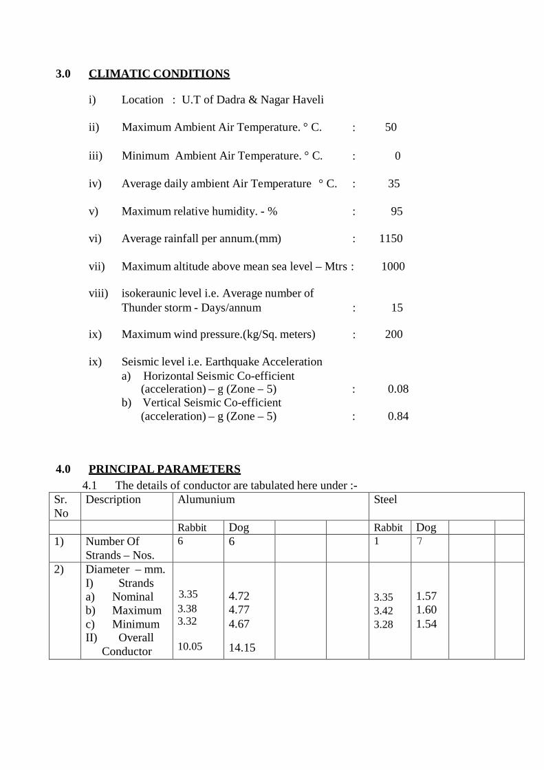
3.0 CLIMATIC CONDITIONS
i) Location : U.T of Dadra & Nagar Haveli
ii) Maximum Ambient Air Temperature. ° C. : 50
iii)
Minimum Ambient Air Temperature. ° C.
:
0
iv) Average daily ambient Air Temperature ° C. : 35
v)
Maximum relative humidity. - %
:
95
vi)
Average rainfall per annum.(mm)
:
1150
vii) Maximum altitude above mean sea level – Mtrs : 1000
viii) isokeraunic level i.e. Average number of Thunder storm - Days/annum : 15
ix)
Maximum wind pressure.(kg/Sq. meters)
:
200
ix)
Seismic level i.e. Earthquake Acceleration
a) Horizontal Seismic Co-efficient (acceleration) – g (Zone – 5) : 0.08
b) Vertical Seismic Co-efficient (acceleration) – g (Zone – 5) : 0.84
4.0 PRINCIPAL PARAMETERS
4.1 The details of conductor are tabulated here under :- Sr. No
Description Alumunium Steel
Rabbit Dog Rabbit Dog 1) Number Of
Strands – Nos. 6 6 1 7
2) Diameter – mm. I) Strands a) Nominal b) Maximum c) Minimum II) Overall Conductor
3.35 3.38 3.32 10.05
4.72 4.77 4.67
14.15
3.35 3.42 3.28
1.57 1.60 1.54

3) Cross Sectional Area– Sq. mm. a) Whole
Conductor b) Each Strand
61.70 8.814
118.5 17.5
8.814
1.94
4) Laying Of Strands – Nos. a) Center b) First Layer c) Second
Layer d) Third Layer
N.A 6 - -
N.A 6 -
-
1 - - -
1 6 -
-
5) Weight (Excl. Wt. Of Grease) – Kg / Km. a) Whole
Conductor b) Strand (At
Nominal Dia.)
214
394
68.75
15.10
6) Calculated D.C. resistance at 20 0C - Ohms / Km a) Whole
Conductor b) Strand
0.5524
0.2792
N.A.
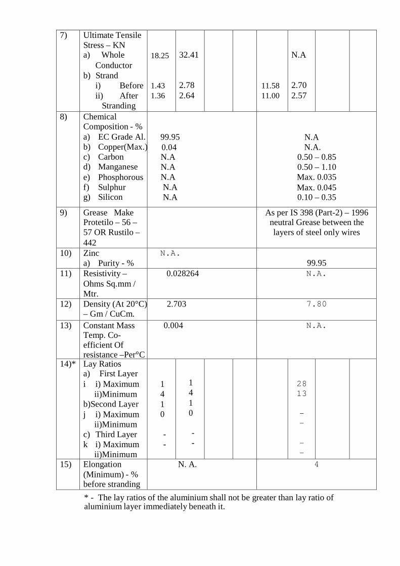
* - The lay ratios of the aluminium shall not be greater than lay ratio of aluminium layer immediately beneath it.
7) Ultimate Tensile Stress – KN a) Whole
Conductor b) Strand
i) Before ii) After
Stranding
18.25 1.43 1.36
32.41
2.78 2.64
11.58 11.00
N.A
2.70 2.57
8) Chemical Composition - % a) EC Grade Al. b) Copper(Max.)c) Carbon d) Manganese e) Phosphorous f) Sulphur g) Silicon
99.95 0.04
N.A N.A N.A N.A N.A
N.A N.A.
0.50 – 0.85 0.50 – 1.10 Max. 0.035 Max. 0.045 0.10 – 0.35
9) Grease Make Protetilo – 56 – 57 OR Rustilo – 442
As per IS 398 (Part-2) – 1996 neutral Grease between the layers of steel only wires
10) Zinc a) Purity - %
N.A. 99.95
11) Resistivity – Ohms Sq.mm / Mtr.
0.028264 N.A.
12) Density (At 20°C)– Gm / CuCm.
2.703 7.80
13) Constant Mass Temp. Co- efficient Of resistance –Per°C
0.004 N.A.
14)* Lay Ratios a) First Layer i i) Maximum
ii)Minimum b)Second Layer j i) Maximum
ii)Minimum c) Third Layer k i) Maximum
ii)Minimum
14 10
- -
14 10
- -
-
28 13
- -
- -
15) Elongation (Minimum) - % before stranding
N. A. 4

5.0 GENERAL TECHNICAL REQUIREMENT
5.1 The ACSR conductor shall be suitable for being installed directly in air supported on suspension insulator strings or anchored through tension insulator strings at the power cross arms of single circuit, double circuit or multi circuit transmission line towers.
5.2 The conductor shall therefore be suitable for satisfactory operation under the tropical climatic conditions listed in the relevant clause. The applicable design particulars of the conductor to be used on these lines is furnished in Annexure - I. "System Particulars".
5.3 Physical Constants Of Materials 5.3.1 Physical constants for Hard-drawn Aluminium. 5.3.1.1 Resistivity : The resistivity of aluminium depends upon its purity and its physical condition. However as per the specified value of purity in this specification the maximum value permitted is 0.028264 ohm. sq. mm / mtr at 20 Deg. C, and this value shall be used for calculation of the maximum permissible value of resistance. This value may be checked from the measured value of the resistance. 5.3.1.2 Density :
At a temperature of 20°C the density of hard drawn aluminium shall be 2.703 g/cm3.
5.3.2 Constant-Mass Temperature Co-efficient of Resistance
5.3.2.1At a temperature of 20°C the constant-mass temperature co-efficient of resistance of hard drawn aluminium measured between two potential points rigidly fixed to the wire, the metal being allowed to expand freely, has been taken as 0.004 per degree celsius.
5.3.3 Co-efficient of Linear Expansion :
5.3.3.1The co-efficient of linear expansion of hard-drawn aluminium at O°C has been taken as 19.3x10⁻⁶ per °C. This value holds good for all practical purposes over the range of temperature from O°C to highest safe operating temperature.
5.4 Physical constants for Galvanised steel wires 5.4.1 Density
5.4.1.1At a temperature of 20°C, the density of galvanised steel wire is to be
taken as 7.80 g/cm3.

5.4.2 Co-efficent of Linear Expansion
In order to obtain uniformity in calculations a value of 11.5 x 10⁻⁶ Per °C may be taken as the value for the co-efficient of Linear Expansion of galvanised steel wires used for the cores of steel-reinforced aluminum conductors.
5.5 Materials
5.5.1 The conductors shall be manufactured from EC grade aluminum rods
suitably hard-drawn on wire drawing machines. The aluminum rods used shall comply with all the relevant ISS, BSS, or other standards to be specified along with the due justifications.
5.5.2 Galvanised steel wire shall be drawn from high carbon steel rods produced
by either acidic or basic open hearth process, electric furnace process or basic oxygen process. All the properties of the steel strands and wires shall confirm to the relevant standards.
5.5.3 The zinc used for galvanising shall be electrolytic high grade Zinc not less than 99.95 percent purity. It shall conform to and satisfy all the requirements of relevant ISS, BSS or other Standards to be specified with the due justification. Galvanising has to be done by hot dip galvanising process. Neutral grease may be applied between the layers of wires, however the weight of the same shall be specified and added to the total weight of the conductor.
NOTE: Lithium soap grease corresponding to Grade II of IS:7623-
1974 (Specification for lithium soap greases) is suitable for such application.
5.5.4 The bidder should specify the source of raw materials along with the proof of last purchases made. The DNHPDCL may reject the tender of the Bidders whose raw material suppliers are found to be supplying any poor quality or non standard materials, to the DNHPDCL or any other purchaser.
5.6 Freedon From Defects
5.6.1 The wires shall be smooth and free from all imperfections such as
spills, splits, slag inclusion, die marks, scratches, fittings, blow-holes, projections, looseness, overlapping of strands, chipping of aluminium layers etc. and all such other defects which may hamper the mechanical & electrical properties of the conductor as also the installation of the conductor at the site etc. Special care should be taken to keep away dirt, grit etc. during stranding.
5.7 Wire Sizes

5.7.1 Nominal Size And Tolerances
The aluminium and galvanised steel wires for the stranded conductor covered by this standard shall have diameters specified in clause 4.1 and shall be within the tolerances indicated therein. The diameter of the steel wires shall be measured over the zinc coating.
5.8 Joints In Wires 5.8.1 Aluminimum Wires
5.8.1.1 No joints shall be permitted in the aluminium wires in the outermost layer
of the ACSR conductor. Joints in the inner layers are permitted, in addition to those made in the base rod or wire before final drawing, but no two such joints shall be less than 15 mtr. apart in the complete stranded conductor. Such joints shall be made by cold pressure butt- welding.
NOTE : Joints are not permitted in the outermost layer of the conductor
in order to ensure a smooth conductor finish and reduce radio interference levels and corona losses on the extra high voltage lines.
5.8.2 Galvanised steel wires
5.8.2.1 There shall be no joints except those in the base rod or wire before
final drawing, in steel wires forming the core of the steel-reinforced aluminium conductor.
5.9 Stranding
5.9.1 The wires used in the construction of galvanised steel reinforced
aluminium conductor shall before stranding and after stranding shall satisfy all the relevant requirements as per the standards indicated or any other standards with due justification.
5.9.2 The zinc used for galvanising shall be electrolytic high grade Zinc. It shall conform to and satisfy all the requirements of relevant standards indicated or any other standards with due justification. Galvanising shall be done by hot dip galvanising process. Neutral grease may be applied between the layers of wires.
NOTE: Lithium soap grease corresponding to Grade II of IS:7623-
1974 (Specification for lithium soap greases) is suitable for such application.
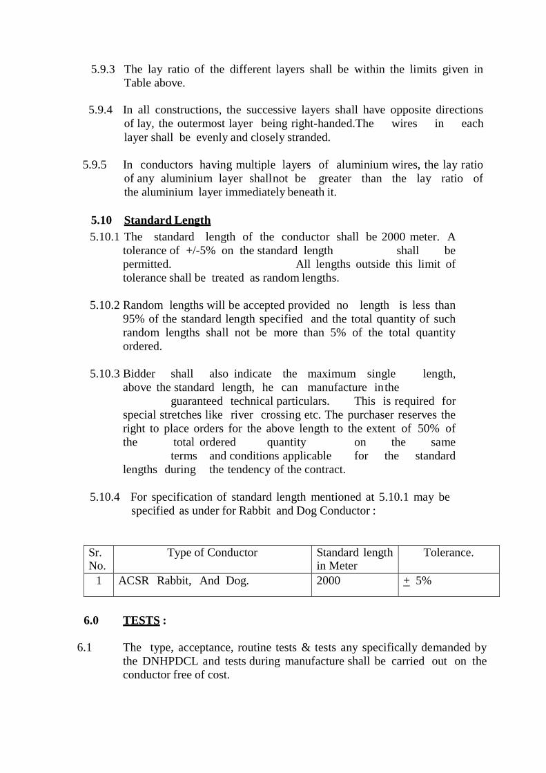
5.9.3 The lay ratio of the different layers shall be within the limits given in Table above.
5.9.4 In all constructions, the successive layers shall have opposite directions
of lay, the outermost layer being right-handed.The wires in each layer shall be evenly and closely stranded.
5.9.5 In conductors having multiple layers of aluminium wires, the lay ratio
of any aluminium layer shall not be greater than the lay ratio of the aluminium layer immediately beneath it.
5.10 Standard Length 5.10.1 The standard length of the conductor shall be 2000 meter. A
tolerance of +/-5% on the standard length shall be permitted. All lengths outside this limit of tolerance shall be treated as random lengths.
5.10.2 Random lengths will be accepted provided no length is less than
95% of the standard length specified and the total quantity of such random lengths shall not be more than 5% of the total quantity ordered.
5.10.3 Bidder shall also indicate the maximum single length,
above the standard length, he can manufacture in the guaranteed technical particulars. This is required for special stretches like river crossing etc. The purchaser reserves the right to place orders for the above length to the extent of 50% of the total ordered quantity on the same terms and conditions applicable for the standard lengths during the tendency of the contract.
5.10.4 For specification of standard length mentioned at 5.10.1 may be
specified as under for Rabbit and Dog Conductor :
Sr. No.
Type of Conductor Standard length in Meter
Tolerance.
1 ACSR Rabbit, And Dog. 2000
+ 5%
6.0 TESTS : 6.1 The type, acceptance, routine tests & tests any specifically demanded by
the DNHPDCL and tests during manufacture shall be carried out on the conductor free of cost.
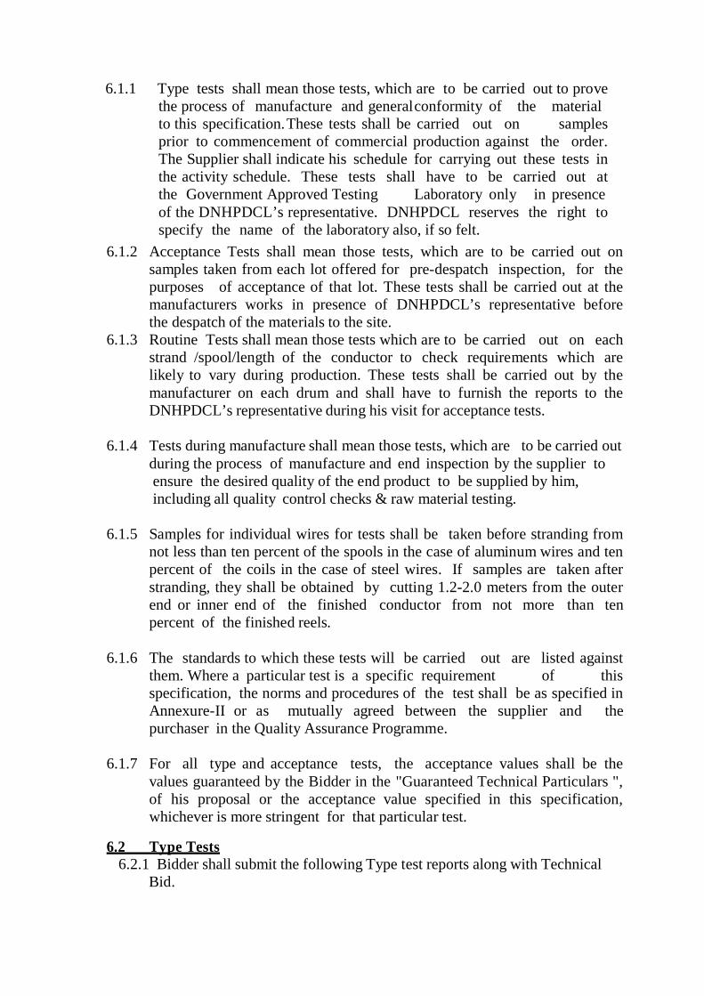
6.1.1 Type tests shall mean those tests, which are to be carried out to prove the process of manufacture and general conformity of the material to this specification. These tests shall be carried out on samples prior to commencement of commercial production against the order. The Supplier shall indicate his schedule for carrying out these tests in the activity schedule. These tests shall have to be carried out at the Government Approved Testing Laboratory only in presence of the DNHPDCL’s representative. DNHPDCL reserves the right to specify the name of the laboratory also, if so felt.
6.1.2 Acceptance Tests shall mean those tests, which are to be carried out on samples taken from each lot offered for pre-despatch inspection, for the purposes of acceptance of that lot. These tests shall be carried out at the manufacturers works in presence of DNHPDCL’s representative before the despatch of the materials to the site.
6.1.3 Routine Tests shall mean those tests which are to be carried out on each strand /spool/length of the conductor to check requirements which are likely to vary during production. These tests shall be carried out by the manufacturer on each drum and shall have to furnish the reports to the DNHPDCL’s representative during his visit for acceptance tests.
6.1.4 Tests during manufacture shall mean those tests, which are to be carried out during the process of manufacture and end inspection by the supplier to ensure the desired quality of the end product to be supplied by him, including all quality control checks & raw material testing.
6.1.5 Samples for individual wires for tests shall be taken before stranding from
not less than ten percent of the spools in the case of aluminum wires and ten percent of the coils in the case of steel wires. If samples are taken after stranding, they shall be obtained by cutting 1.2-2.0 meters from the outer end or inner end of the finished conductor from not more than ten percent of the finished reels.
6.1.6 The standards to which these tests will be carried out are listed against
them. Where a particular test is a specific requirement of this specification, the norms and procedures of the test shall be as specified in Annexure-II or as mutually agreed between the supplier and the purchaser in the Quality Assurance Programme.
6.1.7 For all type and acceptance tests, the acceptance values shall be the
values guaranteed by the Bidder in the "Guaranteed Technical Particulars ", of his proposal or the acceptance value specified in this specification, whichever is more stringent for that particular test.
6.2 Type Tests
6.2.1 Bidder shall submit the following Type test reports along with Technical Bid.

1. Measurement of Diameter (Cl. 13.2) a) Aluminium Wire b) Steel Wire
2. Breaking Load Test (Cl. 13.3) a) Aluminium Wire (before/after) b) Steel Wire (before/after)
3. Ductility Test (Cl. 13.4) a) % Elongation (Steel Wire)(before/after) b) Torsional test (before/after)
4. Wrapping Test (Cl. 13.5) a) Aluminium Wire b) Steel Wire
5. Resistance Test (Cl. 13.6) a) Aluminium Wire b) Conductor
6. Measurement of Lay Ratio (Cl. 13.8) a) First Layer (Steel) b) Outermost Layer (Alu.) c) Beneath Outermost Layer (Alu.)
7. Stress Strain Test (Cl. 13.11) a) On composite conductor b) On steel core
8. Surface Condition Test (Cl. 13.9) 9. Ultimate Breaking Load of stranded conductor (Cl. 13.10)
10. Galvanising Test of steel wire (Cl. 13.7) a) Weight of Zinc coating b) Uniformity of Zinc coating
6.3 Acceptance Tests
a) Visual and dimensional check IS:398(Part II) 1996/Relevant
with latest Ammendment. b) Visual check for joints, scratches etc. and
lengths of conductor - D O -
c) Dimensional check on steel and aluminium strands
IS:398(Part – 2) 1996 or as per this specifications
d) Check for lay ratio of various layers. IS : 398 (Part II) 1996 / Relevant with latest Amendment.
e) Galvanising test on steel strands - D O - f) Torsion and elongation test on steel strands - D O - g) Breaking load test on steel and aluminum
strands. - D O -
h) Wrap test on steel and aluminum strands. - D O - i) DC resistance test on aluminum strands - D O - j) UTS test on welded joint of aluminum strand As per this specification
Note : All the above tests except test mentioned at (j) shall be carried out on
aluminum and steel strands after stranding only.
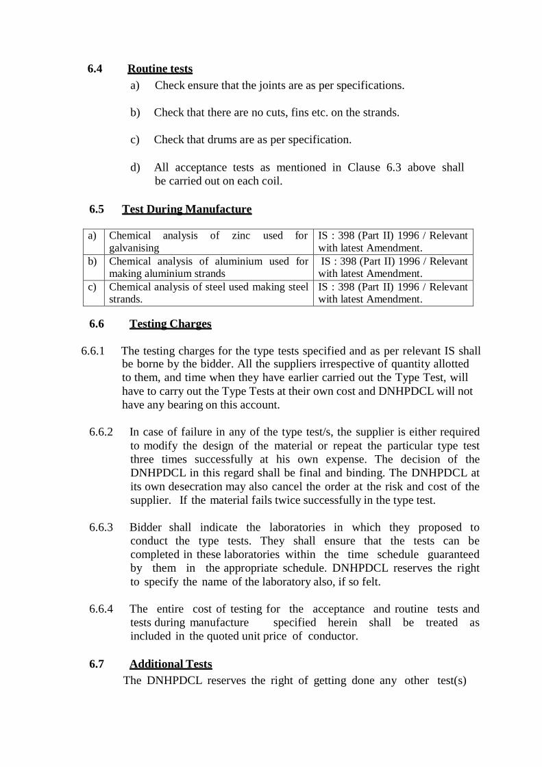
6.4 Routine tests a) Check ensure that the joints are as per specifications.
b) Check that there are no cuts, fins etc. on the strands.
c) Check that drums are as per specification.
d) All acceptance tests as mentioned in Clause 6.3 above shall be carried out on each coil.
6.5 Test During Manufacture
a) Chemical analysis of zinc used for
galvanising IS : 398 (Part II) 1996 / Relevant with latest Amendment.
b) Chemical analysis of aluminium used for making aluminium strands
IS : 398 (Part II) 1996 / Relevant with latest Amendment.
c) Chemical analysis of steel used making steel strands.
IS : 398 (Part II) 1996 / Relevant with latest Amendment.
6.6 Testing Charges
6.6.1 The testing charges for the type tests specified and as per relevant IS shall
be borne by the bidder. All the suppliers irrespective of quantity allotted to them, and time when they have earlier carried out the Type Test, will have to carry out the Type Tests at their own cost and DNHPDCL will not have any bearing on this account.
6.6.2 In case of failure in any of the type test/s, the supplier is either required
to modify the design of the material or repeat the particular type test three times successfully at his own expense. The decision of the DNHPDCL in this regard shall be final and binding. The DNHPDCL at its own desecration may also cancel the order at the risk and cost of the supplier. If the material fails twice successfully in the type test.
6.6.3 Bidder shall indicate the laboratories in which they proposed to
conduct the type tests. They shall ensure that the tests can be completed in these laboratories within the time schedule guaranteed by them in the appropriate schedule. DNHPDCL reserves the right to specify the name of the laboratory also, if so felt.
6.6.4 The entire cost of testing for the acceptance and routine tests and
tests during manufacture specified herein shall be treated as included in the quoted unit price of conductor.
6.7 Additional Tests
The DNHPDCL reserves the right of getting done any other test(s)

of reasonable nature carried out at Supplier's premises, at site, or in any other place in addition to the aforesaid type, acceptance and routine tests to satisfy himself that the material comply with the specifications. In such case all the expenses will be to Suppliers account.
6.8 Sample Batch For Type Testing
6.8.1 The Supplier shall offer at least three (3) drums for selection of samples
required for conducting all the type tests. 6.8.2 The Supplier is required to carry out all the acceptance tests successfully
in the presence of Purchaser's representative before despatch of the selected sample to the testing laboratory for type test..
6.9 Test Reports
6.9.1 Copies of type test reports shall be furnished in at least two(2) copies
along with one original. One copy shall be returned duly certified by the Purchaser only after which the material already inspected i.e. the materials manufactured for selection of sample for type test, shall be dispatched on receipt of Despatch Instructions from the Chief Engineer (Projects).
6.9.2 Record of routine test reports shall be maintained by the Supplier at his
works for periodic inspection by the purchasers representative. 6.9.3 Test Certificates of test during manufacture shall be maintained by the
Bidder. These shall be produced for verification as and when desired by the Purchaser.
6.10 Test Facilities 6.10.1 The following additional facilities shall be available at Supplier's
works:-
a) Calibration Reports from Government approved testing laboratory of various testing and measuring equipment including tensile testing machine, resistance measurement facilities, burette,
thermometer, barometer etc.
b)
Standard resistance for calibration of resistance bridges.
c)
Finished conductor shall be checked for length verification
and surface finish on separate rewinding machine at reduced speed (variable from 8 to 16 meters per minute). The rewinding facilities shall have appropriate clutch system and free of vibrations, jerks etc. with transverse layering facilities.

d) The bidder should have all the routine and acceptance testing facilities, in house.
7.0 INSPECTION
7.1 The Purchaser's representative shall at all times be entitled to have access
to the works and all places of manufacture where conductor shall be manufactured and the representative shall have full facilities for unrestricted inspection of the Suppliers works raw materials and process of manufacture and conducting necessary tests as may be deemed fit, for certifying the quality of product.
7.2 The Supplier shall keep the Purchaser informed in advance of the time of
starting and of the progress of manufacture of conductor in its various stages so that arrangements can be made for inspection.
7.3 No material shall be despatched from its point of manufacture before
it has been satisfactorily inspected, tested, and necessary despatch instructions are issued in writing, except for the cases where waiver of inspection is granted by competent authority of the DNHPDCL, and even in this case also written dispatch instructions will be issued. Any dispatches before the issue of Dispatch Instructions in writing will be liable for rejection and non acceptance by the consignee.
7.4 The acceptance of any quantity of material shall in no way relieve the
Supplier of any of his responsibilities for meeting all requirements of the specification, and shall not prevent subsequent rejection if such material is later found to be defective.
7.5 At least 5% of the total number of drums subject to minimum of two in
any lot put up for inspection, shall be selected at random to ascertain the length of conductor by following method: "At the works of the manufacturer of the conductor, the conductor shall be transferred from one drum to another at the same time measuring its length with the help of a graduated pulley & Cyclometer. The difference in the average length thus obtained and as declared by the Supplier in the packing list shall be applied to all the drums if the conductor is found short during checking."
7.6 The sample cut of from any numbers of drums for carrying out any type of
tests will be to the suppliers account.
8.0 QUALITY ASSURANCE PLAN 8.1 The bidder shall invariably furnish following information along with
his offer, failing which his offer shall be rejected.
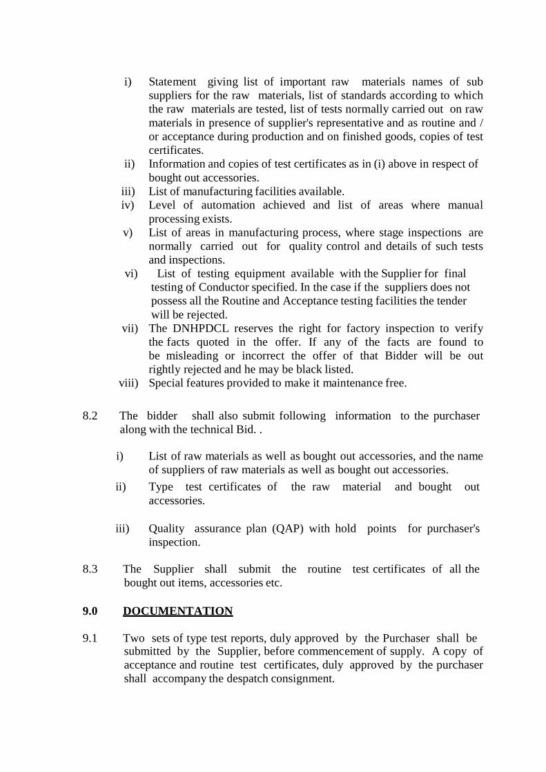
i) Statement giving list of important raw materials names of sub
suppliers for the raw materials, list of standards according to which the raw materials are tested, list of tests normally carried out on raw materials in presence of supplier's representative and as routine and / or acceptance during production and on finished goods, copies of test certificates.
ii) Information and copies of test certificates as in (i) above in respect of bought out accessories.
iii) List of manufacturing facilities available. iv) Level of automation achieved and list of areas where manual
processing exists. v) List of areas in manufacturing process, where stage inspections are
normally carried out for quality control and details of such tests and inspections.
vi) List of testing equipment available with the Supplier for final testing of Conductor specified. In the case if the suppliers does not possess all the Routine and Acceptance testing facilities the tender will be rejected.
vii) The DNHPDCL reserves the right for factory inspection to verify the facts quoted in the offer. If any of the facts are found to be misleading or incorrect the offer of that Bidder will be out rightly rejected and he may be black listed.
viii) Special features provided to make it maintenance free.
8.2 The bidder shall also submit following information to the purchaser
along with the technical Bid. .
i) List of raw materials as well as bought out accessories, and the name of suppliers of raw materials as well as bought out accessories.
ii) Type test certificates of the raw material and bought out accessories.
iii) Quality assurance plan (QAP) with hold points for purchaser's
inspection.
8.3 The Supplier shall submit the routine test certificates of all the bought out items, accessories etc.
9.0 DOCUMENTATION
9.1 Two sets of type test reports, duly approved by the Purchaser shall be submitted by the Supplier, before commencement of supply. A copy of acceptance and routine test certificates, duly approved by the purchaser shall accompany the despatch consignment.

9.2 The manufacturing of the conductor shall be strictly in accordance with the approved drawings and no deviation shall be permitted without the written approval of the Purchaser. All manufacturing and fabrication work in connection with the conductor prior to the approval of the drawing shall be at supplier's risk.
9.3 Approval of drawing etc. by the purchaser shall not relieve the Supplier of his responsibility and liability for ensuring correctness and correct interpretation of the latest revision of applicable standards, rules and codes of practices. The conductor shall conform in all respects to high standards of engineering, design, workmanship and latest revisions of relevant standards at the time of ordering and purchaser shall have the power to reject any work or material which in his judgement is not in full accordance therewith.
10.0 PACKING & FORWARDING 10.1 The conductor shall be supplied in non-returnable strong wooden drums
provided with lagging of adequate strength, and displacement during transit, storage and subsequent handling and stringing operations in the field. The drums shall confirm to IS:1778-1980 except otherwise specified hereinafter.
10.2 The drums shall be suitable for wheel mounting and for jetting off the
conductor under a minimum controlled tension of the order of 5 kN. 10.3 The bidder should submit the proposed drum drawings & GTP
along with the bid. However, the same shall be in line with the requirements as stated herein. After placement of the Letter of Award, the Supplier shall submit four copies of fully dimensioned drawing of the drum, for Purchaser's approval before taking up manufacturing of Conductor and or drums. After getting approval from the Purchaser, Supplier shall submit 6 more copies of the approved drawing to Purchaser for further distribution and field use at Purchaser's end.
10.4 All wooden components shall be manufactured out of seasoned soft
wood free from defects that may materially weaken the component parts of the drums. Preservative treatment for anti-termite/anti-fungus (Aldrime / Aldruse) etc. shall be applied to the entire drum with preservatives of a quality which is not harmful to the conductor nor to the persons using or storing the same.
10.5 The flanges shall be of three ply construction with each ply at right angles
to the other and nailed together. The nails shall be driven from the inside face flange, punched and then clenched on the outer face. The tolerance in thickness of each ply shall be +3 mm only. There shall be at least 3 nails per plank of ply with maximum nail spacing of 75 mm. Where a slot is cut in the flange to receive the inner end of the conductor, the entrance shall be in the line with the periphery of the barrel.

10.6 The wooden battens used for making the barrel of the conductor shall be
of segmental type. These shall be nailed to the barrel supports with at least two nails. The battens shall be closely butted and shall provide a round barrel with smooth external surface. The edges of the battens shall be rounded or chamfered to avoid damage to the conductor.
10.7 Barrel studs shall be used for construction of drums. The flanges shall be holed and the barrel supports slotted to receive them. The barrel studs shall be threaded over a length on either end, sufficient to accommodate washers, spindle plates and nuts for fixing flanges at the required spacing. Barrel studs should be tack welded with the nuts after tightening.
10.8 Normally, the nuts on the studs shall stand proud of the flanges. All the
nails used on the inner surface of the flanges and the drum barrel shall be countersunk. The ends of barrel shall generally be flushed with the top of the nuts.
10.9 The complete drum including inner cheek of the flanges and drum barrel surface shall be painted with a bitumen based paint.
10.10 Before reeling, card board or double corrugated or thick bituminised
waterproof bamboo paper shall be secured to the drum barrel and inside of flanges or the drum by means of a suitable commercial adhesive material. The paper should be dried before use. Medium grade Kraft paper shall be used in between the layers of the conductor. After reeling the conductor, the exposed surface of the outer layer of conductor shall be wrapped with thin polythene sheet across the flanges to preserve the conductor from dirt, grit and damage during transportation and handling and also to prevent ingress of rain water during storage/transport.
10.11 A minimum space of 75 mm shall be provided between the
inner surface of the external protective layer and outer layer of the conductor.
10.12 Each batten shall be securely nailed across grains as far as
possible to the flange edges with at least 2 nails per end. The length of the nails shall not be less than twice the thickness of the battens. The nail shall not protrude above the general surface and shall not have exposed sharp edges or allow the battens to be released due to corrosion.
10.13 Outside the protective layer, there shall be minimum of
two binder consisting of hoop iron/galvanised steel wire. Each protective layer shall have two recess to accommodate the binders.
10.14 The conductor ends shall be properly sealed and secured

with the help of U-nails on one side of the flanges. The end securing shall be done by taking out at least 500 mm. of steel core on either ends and sealing it with U-nails. The composite conductor shall be banded by use of galvanised steel wire/aluminium.
10.15 Wire at three locations at the most 75 mm apart or less covered
with PVC adhesive tape so as to avoid loosening of conductor layers in transit and handling.
10.16 Only one length of conductor shall be wound on each drum.
Name of
conductor Langth Drum Size Plange Dia
(A)
Barral Dia (B)
Travers
(W)
No. of TIE ROD
Thickness
(T)
1 Rabbit Conductor
2000 + 5%
Drawing to be submitted as per requirement (IS 1778,1980) 32 + 32+32=96
2 Dog Conductor 2000 + 5%
Drawing to be submitted as per requirement (IS 1778,1980) 32 + 32+32=96
10.17 If any bidder wishes to supply the conductor in the steel drums the same will be acceptable, however free of cost.
TEST PROCEDURES 1.0 UTS TEST ON STRANDED CONDUCTOR
1.1 Circles perpendicular to the axis of the conductor shall be marked at two
places on a sample of conductor of minimum 5 m length suitably compressed with dead end clamps at either end. The load shall be increased at a steady rate up to (50%) of UTS and held for one minute, the circles drawn shall not be distorted due to Relative movement of strands. Thereafter the load shall be increased at a steady rate to (100%) of UTS and held for one minute. The applied load shall then be increased until the failing load is reached and the value recorded.
2.0 SURFACE CONDITION TEST
2.1 A sample of the finished conductor for use in 11 KV system having a minimum recommended length of 5 meters with compression type dead end clamps compressed on both ends in such a manner as to permit the conductor to take its normal straight line shape, shall be subjected
to a tension of 50 percent of the UTS of the conductor. The surface shall not depart from its cylindrical shape nor shall the strands move relative to each other so as to get out of place or disturb the longitudinal smoothness of conductor. The measured diameter at any place shall be not be less than
the sum of the minimum specified diameters of the individual aluminium and steel strands as given in this specification.
3.0 D.C. RESISTANCE TEST ON STRANDED CONDUCTOR
3.1 On a conductor sample of minimum 5m length two contact clamps shall be
fixed with a pre-determined bolt torque. The resistance shall be measured by a kelvin double bridge by placing the clamps initially zero meter and subsequently one meter apart. The test shall be repeated at least five times and the average value shall be recorded. The value obtained shall be corrected to the value at 20 deg. C as per Clause No. 12.8 of IS : 398 (Part V) / 1996. The resistance corrected at 20 deg. C shall conform to the requirements of this specification.
4.0 STRESS-STRAIN TEST SURFACE CONDITION TEST
4.1 This test is contemplated to collect the creep data of the conductor from the
Bidder. A sample of conductor of minimum 10 meters length shall be suitably compressed with dead end clamps.
4.2 Test Set - Up
4.2.1 The test sample shall be supported in a through over its full length and the
through shall be adjusted such that the conductor does not get lifted by more than 10mm under tension. This shall be ascertained by actual measurement.
4.2.2 The distance between the clamp and the sleeve mouth shall be monitored
with calipers during the test to ensure that after the test, it does change by more than +/- 0.1 mm from the value before the test.
4.2.3 The conductor strain shall be evaluated from the measured displacements at
the two ends of the gauge length of the sample. The gauge reference targets shall be attached to the clamps which lock the steel and aluminium wires together. Target plates may be used with dial gauges on displacement transducers and care shall be taken to position the plates perpendicular to the conductor. Twisting the conductor, lifting it and moving it from side-to- side by the maximum amounts expected during the test should introduce no more than 0.3 mm error in the reading.
4.3 Test Loads for Complete Conductor
4.3.1 The loading conditions for repeated stress-strain tests for complete
conductor shall be as follows : 4.3.1.1 1 KN load shall be applied initially to straighten the conductor. The load

shall be removed after straightening and then strain gauges are to be set at zero at the zero tension.
4.3.2 For non-continuous stress-strain data, the strain readings at 1 KN
intervals at lower tension and 5 KN intervals above 30% of UTS shall be recorded.
4.3.3 The sample shall be reloaded to 50% of UTS and held for 1 hour. Readings are to be noted after 5, 10, 15, 30, 45 and 60 Minutes. The load shall then be released.
4.3.4 Reloading up to 70% of UTS shall be done and held for 1 hour.
Readings are to be noted after 5,10,15,30,45 and 60 minutes and then load shall be released.
4.3.5 Reloading up to 85% of UTS shall be done and held for 1 hour.
Readings are to be noted after 5,10,15,30,45 and 60 minutes and then load shall be released.
4.3.6 Tension shall be applied again and shall be increased uniformly until the
actual breaking strength is reached. Simultaneous readings of tension and elongation shall be recorded up to 90% of UTS at the intervals described under Clause 6.3.5.
4.4 Test Loads For Steel Core Only
The loading conditions for repeated stress-strain tests for the steel core of ACSR shall be a follows :
4.4.2 The test shall consist of successive application of load applied in a
manner similar to that for one complete conductor at 30%, 50%, 70% and 85% of UTS.
4.4.3 The steel core shall be loaded until the elongation at the beginning of
each hold period corresponds to that obtained on the complete conductor at 30%, 50%, 70% and 85% of UTS respectively.
4.5 Stress Strain Curves
The design stress-strain curve shall be obtained by drawing a smooth curve through the 0.5 and 1 hour points at 30%, 50% and 70% of UTS loading. The presence of any aluminium slack that can be related to any observed extrusion entering the span from the compression dead ends shall be removed from the lower ends of the design curves. Both the laboratory and design stress-strain curves shall be submitted to the purchaser along with test results. The stress-strain data obtained during the test shall be corrected to the standard temperature i.e. 20 deg. C.
5.0 CHEMICAL ANALYSIS OF ZINC
Samples taken from the zinc ingots shall be chemically / spectrographically analysed. The same shall be in conformity to the requirements stated in this specification.
6.0 CHEMICAL ANALYSIS OF ALUMINIUM AND STEEL
Samples taken from the Aluminium ingots/coils/strands shall be chemically / spectrographically analysed. The same shall be in conformity to the requirements stated in this specification.
7.0 VISUAL AND DIMENSIONAL CHECK ON DRUMS
The drums shall visually and dimensionally checked to ensure that they conform to the requirements of this specification.
8.0 VISUAL CHECK FOR JOINTS, SCRATCHES ETC.
Conductor drums shall be rewound in the presence of the inspecting officer. The inspector shall visually check the scratches, joints, etc. and that the conductor generally conform to the requirements of the specification.
9.0 DIMENSIONAL CHECK OF STEEL AND ALUMINIUM STRANDS
The individual strands shall be dimensionally checked to ensure that they conform to the requirements to this specification.
10.0 CHECK FOR LAY-RATIOS OF VARIOUS LAYERS
The lay-ratios of various layers shall be checked to ensure that they conform to the requirements of this specification.
11.0 GALVANISING TEST
The test Procedure shall be as specified in relevant IS. The material shall conform to the requirements of this specification.
12.0 TORSION AND ELONGATION TESTS ON STEEL STRANDS
The test procedures shall be as per the relevant IS In torsion test, the number of compete twists before fracture shall not be less than 18 on a length equal to 100 times the standard diameter of the strand. In case test sample length is less or more than 100 times the standard diameter of
the strand, the minimum number of twist will be proportionate to the length and if number comes in the fraction then it will be rounded off to next higher whole number. In elongation test, the elongation of the strand shall not be less than 4% for a gauge length of 200 mm.
13.0 BREAKING LOAD TEST ON WELDED ALUMINIUM STRAND
Two Aluminum wire shall be welded as per the approved quality plan and shall be subjected to tensile load. The welded point of the wire shall be able to withstand the minimum breaking load of the individual strand specified in this specification.
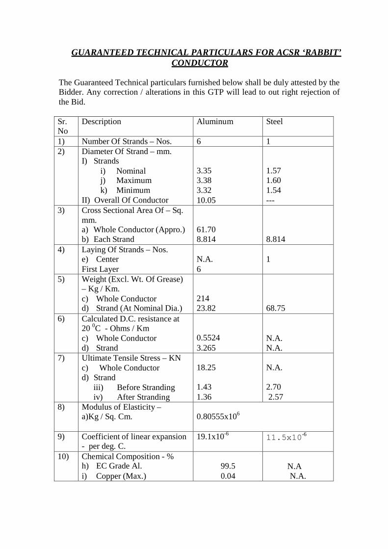
GUARANTEED TECHNICAL PARTICULARS FOR ACSR ‘RABBIT’ CONDUCTOR
The Guaranteed Technical particulars furnished below shall be duly attested by the Bidder. Any correction / alterations in this GTP will lead to out right rejection of the Bid.
Sr. No
Description Aluminum Steel
1) Number Of Strands – Nos. 6 1 2) Diameter Of Strand – mm.
I) Strands i) Nominal j) Maximum k) Minimum
II) Overall Of Conductor
3.35 3.38 3.32 10.05
1.57 1.60 1.54 ---
3) Cross Sectional Area Of – Sq. mm. a) Whole Conductor (Appro.) b) Each Strand
61.70 8.814
8.814
4) Laying Of Strands – Nos. e) Center First Layer
N.A. 6
1
5) Weight (Excl. Wt. Of Grease) – Kg / Km. c) Whole Conductor d) Strand (At Nominal Dia.)
214 23.82
68.75
6) Calculated D.C. resistance at 20 0C - Ohms / Km c) Whole Conductor d) Strand
0.5524 3.265
N.A. N.A.
7) Ultimate Tensile Stress – KN c) Whole Conductor d) Strand
iii) Before Stranding iv) After Stranding
18.25
1.43 1.36
N.A.
2.70 2.57
8) Modulus of Elasticity – a)Kg / Sq. Cm.
0.80555x10⁶
9) Coefficient of linear expansion - per deg. C.
19.1x10⁻⁶ 11.5x10⁻⁶
10) Chemical Composition - % h) EC Grade Al. i) Copper (Max.)
99.5 0.04
N.A N.A.

j) Carbon k) Manganese l) Phosphorous m) Sulphur n) Silicon
N.A N.A N.A N.A N.A
0.50 – 0.85 0.50 – 1.10 Max. 0.035 Max. 0.045 0.10 – 0.35
11) Grease Make Protectilo – 56 57 or Rustilo - 442
As per IS 389 (Part-2) – 1996 Neutral Grease between the layers of steel
wires only
12) Zinc Purity - % 99.95
13) Resistivity – Ohms Sq. mm / Mtr.
0.028264 N.A.
14) Density (At 20°C) – Gm / CuCm.
2.703 7.80
15) Constant Mass Temp. Co- efficient Of resistance – Per°C
0.004 N.A.
16)* Lay Ratios(1+6) d) First Layer l i) Maximum
ii)Minimum
14 10
17) Elongation (Minimum) - % Before stranding
N. A. 4
Signature of the Bidder : Name : D e s i g n a t i on : Date :
Authorised common rubber Stamp / seal of the bidder :