Embed Size (px)
Citation preview
3
AAIB Bulletin S4/2014 SPECIAL
Farnborough HouseBerkshire Copse RoadAldershot, Hants GU11 2HH
Tel: 01252 510300Fax: 01252 376999www.aaib.gov.uk
This Special Bulletin contains facts which have been determined up to the time of issue. It is published to inform the aviation industry and the public of the general circumstances of accidents and serious incidents and should be regarded as tentative and subject to alteration or correction if additional evidence becomes available.
© Crown copyright 2014
AAIBAir Accidents Investigation Branch
SERIOUS INCIDENT
Aircraft Type and registration: B787-8, ET-AOP
No & Type of Engines: 2 General Electric GEnx-1B turbofan engines
Year of Manufacture: 2012 (MSN 34744)
Location: London Heathrow Airport Date & Time (UTC): 12 July 2013 at 1534 hrs
Type of Flight: Not applicable
Persons on Board: None
Injuries: Not applicable
Nature of Damage: Extensive heat damage in upper portion of rear fuselage
Information Source: AAIB Field Investigation
Introduction
This Special Bulletin contains information on the progress of the investigation into a ground fire on an unoccupied Boeing 787-8, registration ET-AOP, at London Heathrow Airport on 12 July 2013. It follows the publication of Special Bulletin S5/2013 on 18 July 2013.
The AAIB are assisted in the investigation by Accredited Representatives from the National Transportation Safety Board (NTSB) (representing the State of Design and Manufacture), the Civil Aviation Authority of Ethiopia (representing the State of Registry and the Operator) and the Transportation Safety Board (TSB) of Canada (representing the State of component manufacture), with technical advisors from the Federal Aviation Administration (FAA), the operator and the aircraft and component manufacturers.
4© Crown copyright 2014
AAIB Bulletin: S4/2014 ET-AOP EW/C2013/07/01
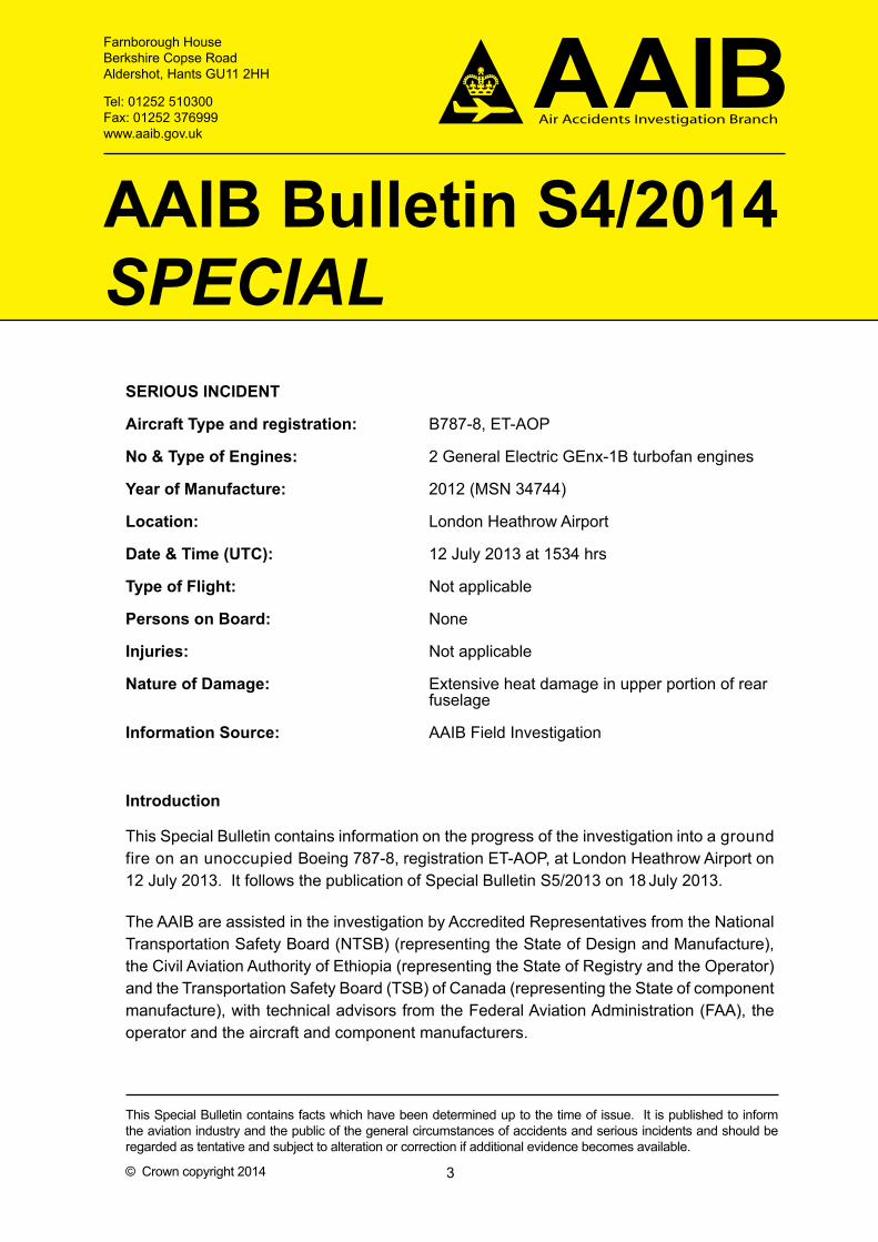
In Special Bulletin S5/2013, the AAIB reported the existence of extensive heat damage in the upper portion of the aircraft’s rear fuselage, particularly in an area coincident with the location of the Emergency Locator Transmitter (ELT). The absence of any other aircraft systems in this area containing stored energy capable of initiating a fire, together with evidence from forensic examination of the ELT, led the investigation to conclude that the fire originated within the ELT battery.
Five Safety Recommendations are made.
Description of the ELT
The ELT is a location device, designed to notify rescue authorities of an aircraft’s location in the event of an emergency. The ELT system installed on the B787-8 is a Honeywell RESCU 406AFN Automatic Fixed ELT, manufactured under contract by Instrumar Limited. The ELT transmitter unit (TU) is located in the aft fuselage crown above the passenger cabin ceiling, to the left of the aircraft centreline, and is mounted on two adjacent fuselage frames, between two thermo-acoustic insulation blankets. The ELT is activated automatically by an internal acceleration sensor, or manually by the flight crew. Unless activated it operates in ‘armed’ mode, using no power.
Examination of the ELT
CT1 scans and a teardown examination of the ELT revealed that the internal battery pack had experienced severe disruption, exhibiting evidence of a very high-energy thermal event, consistent with having experienced a thermal runaway2. All five cell cases had been breached and burnt battery material had been ejected into the battery compartment and outside of the ELT case.
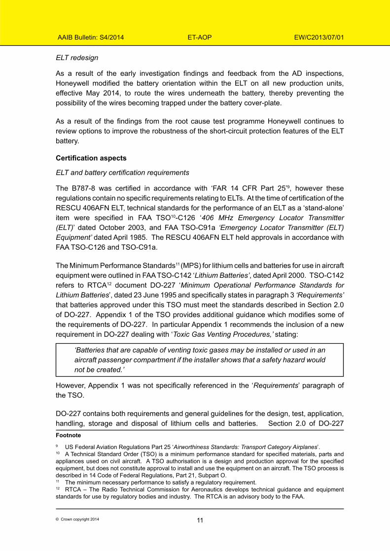
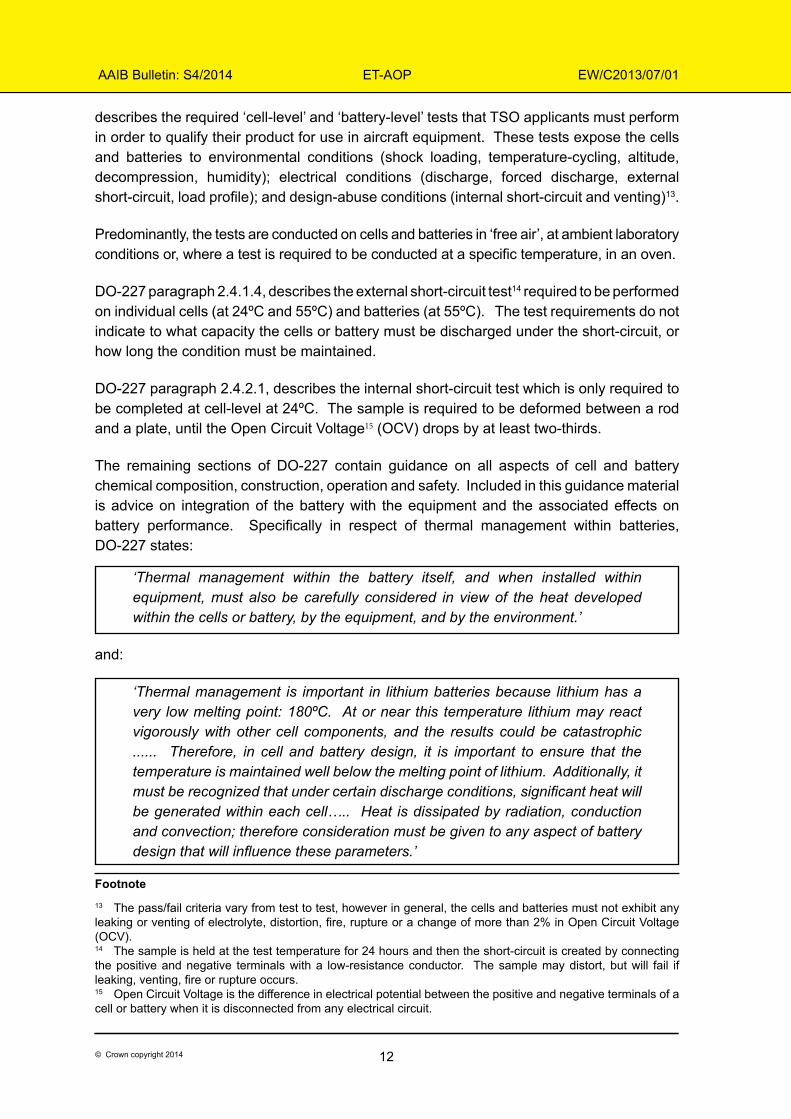
Significantly, the ELT battery wires were found to be improperly installed, in that they had been crossed and pinched together between the battery cover-plate and the ELT case, adjacent to one of the cover-plate fasteners (Figures 1 and 2). The cover-plate was notably bulged in this location, as the wires prevented it from sitting flush against the ELT case.
Due to the fire damage it was not possible to determine the pre-incident condition of the insulation in the area where the wires were pinched, nor the gasket which normally sits between the cover-plate and the ELT case. However, metallurgical analysis revealed strong evidence of metal-to-metal contact between the positive wire and the underside of the battery cover-plate. The surface treatment of the aluminium cover-plate had been worn away in the contact location, indicating that the integrity of the insulation may have become compromised over time, exposing the copper conductor to the cover-plate. The ELT case is electrically grounded to the aircraft Current Return Network. As such, direct
Footnote1 Computed Tomography.2 In the case of lithium batteries, the term ‘thermal runaway’ refers to a self-sustaining, uncontrollable increase in temperature and pressure. It is an exothermic reaction, releasing more heat energy during the reaction than was absorbed to initiate and maintain the reaction. Thermal runaway can culminate in a cell exhibiting violent venting of toxic or flammable gases or electrolyte, decomposition, fire and explosion. The heat released by the affected cell can also heat adjacent cells, such that the failure propagates to other cells in the battery.

5© Crown copyright 2014
AAIB Bulletin: S4/2014 ET-AOP EW/C2013/07/01
See Figure 2
Batterycompartment
Footprint ofbattery cover-plate
Positive wire
Negative wire
Contact pointwith batterycover-plate
Figure 1ELT case with battery cover-plate removed; tops of battery cells visible
Figure 2Crossed and pinched ELT battery wires
6© Crown copyright 2014
AAIB Bulletin: S4/2014 ET-AOP EW/C2013/07/01
contact between the positive conductor and the cover-plate could have provided a path for current to flow through the battery circuit to electrical ground, essentially creating a ‘short-circuit’ condition.
The nature of the battery failure was such that much of the battery material was consumed, and that which remained was extremely fragile. Therefore, despite extensive forensic examination and CT scanning of the battery and the individual cells, it has not been possible to determine with certainty the sequence of cell failures within the battery or the pre-failure state of the safety features in the circuit.
Description of the ELT battery
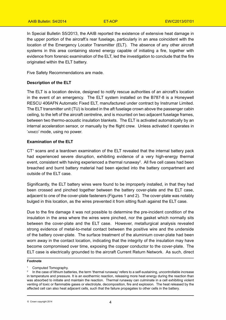
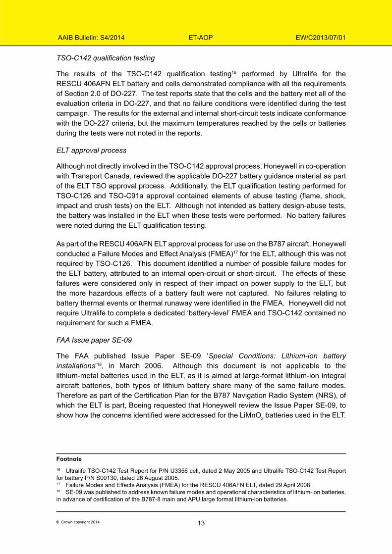
The ELT is powered by a five-cell, non-rechargeable ‘lithium-metal’3 battery, installed in the transmitter unit (Figure 3) and manufactured by Ultralife Corporation, under contract to Instrumar Limited.
Figure 3 ELT battery pack and ELT transmitter unit, showing battery compartment
Each of the Lithium-Manganese Dioxide (LiMnO2) ‘D-cells’4 has a nominal voltage of 3 V and the cells are connected in series to provide a 15 V battery, with a nominal capacity of 11.1 ampere-hours (Ah) (Figure 4). The battery is rated to a maximum continuous discharge current of 3.3 amps. Two external battery wires connect the positive and negative terminals of the battery to the ELT power supply circuit card. The chemistry in the LiMnO2 cells is considerably different to that used in the rechargeable large-format lithium-ion cells used in the B787 main and APU batteries.
Footnote
3 ‘Lithium-metal’ batteries, also known as ‘lithium primary’ batteries, are high-energy electrical storage devices that rely on electrochemical reactions to deliver energy. They are non-rechargeable batteries in which the anode is made from a layer of metallic lithium. 4 A ‘D-cell’ is a cylindrical cell with a nominal diameter of 33.2 mm and a length of 61.5 mm.
Batterypull-tabs
Battery wiresand connector
ELT wires and connector
7© Crown copyright 2014
AAIB Bulletin: S4/2014 ET-AOP EW/C2013/07/01
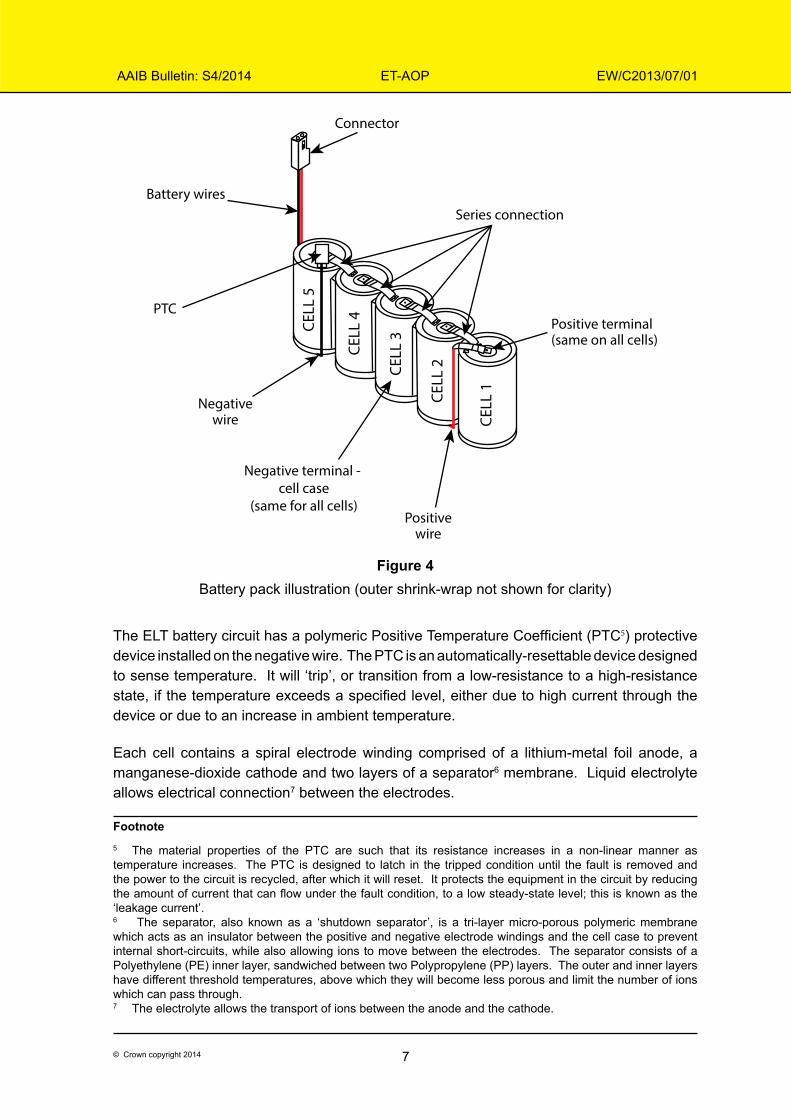
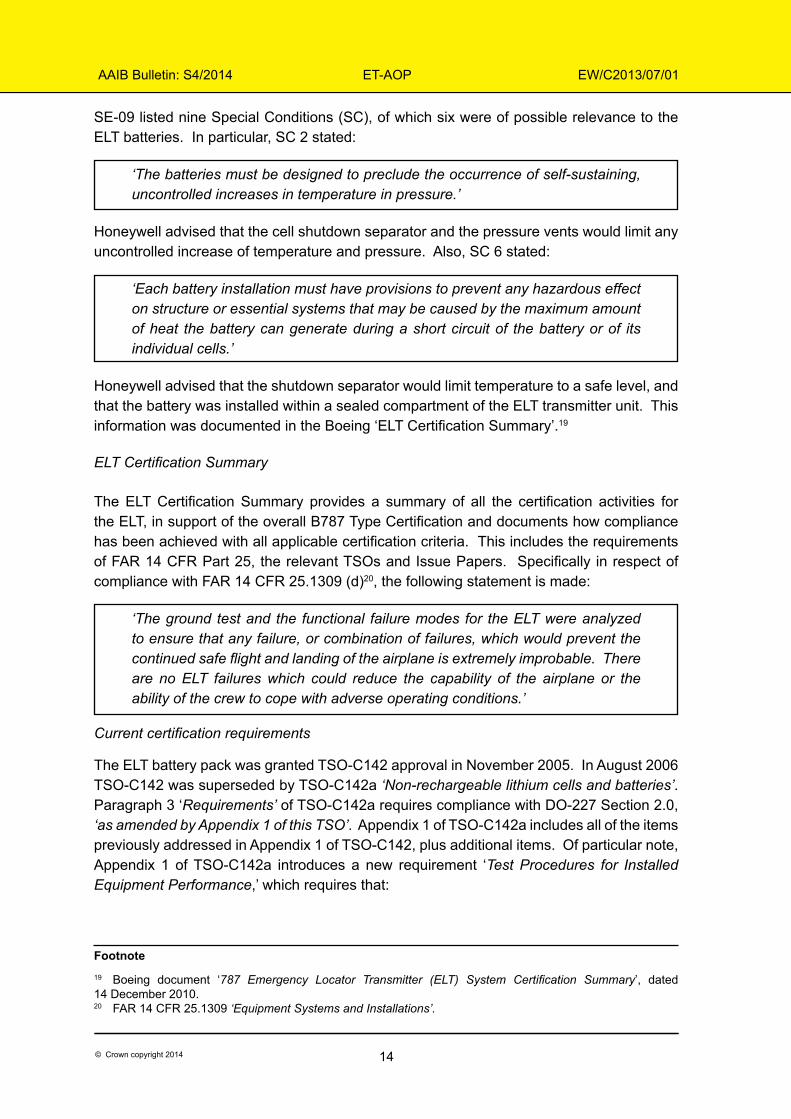
Figure 4Battery pack illustration (outer shrink-wrap not shown for clarity)
The ELT battery circuit has a polymeric Positive Temperature Coefficient (PTC5) protective device installed on the negative wire. The PTC is an automatically-resettable device designed to sense temperature. It will ‘trip’, or transition from a low-resistance to a high-resistance state, if the temperature exceeds a specified level, either due to high current through the device or due to an increase in ambient temperature.
Each cell contains a spiral electrode winding comprised of a lithium-metal foil anode, a manganese-dioxide cathode and two layers of a separator6 membrane. Liquid electrolyte allows electrical connection7 between the electrodes.
Footnote5 The material properties of the PTC are such that its resistance increases in a non-linear manner as temperature increases. The PTC is designed to latch in the tripped condition until the fault is removed and the power to the circuit is recycled, after which it will reset. It protects the equipment in the circuit by reducing the amount of current that can flow under the fault condition, to a low steady-state level; this is known as the ‘leakage current’.6 The separator, also known as a ‘shutdown separator’, is a tri-layer micro-porous polymeric membrane which acts as an insulator between the positive and negative electrode windings and the cell case to prevent internal short-circuits, while also allowing ions to move between the electrodes. The separator consists of a Polyethylene (PE) inner layer, sandwiched between two Polypropylene (PP) layers. The outer and inner layers have different threshold temperatures, above which they will become less porous and limit the number of ions which can pass through.7 The electrolyte allows the transport of ions between the anode and the cathode.
CELL
1CELL
2CELL
3
CELL
4CELL
5
Connector
Series connection
Positive terminal (same on all cells)
Battery wires
PTC
Negativewire
Positivewire
Negative terminal - cell case
(same for all cells)
8© Crown copyright 2014
AAIB Bulletin: S4/2014 ET-AOP EW/C2013/07/01
Design considerations and failure modes of lithium batteries
Lithium-metal is a very reactive material with a high energy density, which makes it capable of delivering high currents, long operational life and small cell sizes when used in batteries. However, because of the energetic materials used, lithium-metal batteries require proper design, test, utilisation and storage for use in aircraft applications.
In particular, lithium-metal batteries are sensitive to certain forms of thermal, electrical or mechanical abuse. Known failure modes of lithium-metal batteries include external short-circuit in the battery circuit and internal short-circuit between electrodes, both of which can lead to rapid and uncontrolled discharge, over-discharging, external heating or self-heating. Any of these conditions can elevate the temperature within a cell and if the operating temperature is exceeded by a sufficient margin, the cell pressure will increase. If the heat generated by a cell is greater than the heat it can dissipate, the cell will begin to decompose and may result in thermal runaway.
Cell and battery design therefore typically include thermal protection devices and other safety features to mitigate against the risk of thermal runaway. The cells of the ELT battery have two safety vents in the base of the cell, intended to release pressure if a thermal event occurs; the cell separator is designed to become less porous above a certain threshold temperature and shut down the electrochemical reaction within the cell. The PTC is intended to protect the battery from external short-circuits, over-current and over-temperature conditions by limiting the amount of current that can flow under the fault condition.
Root cause testing and analysis
To support the AAIB investigation, the aircraft and ELT manufacturers undertook an extensive programme of testing and analysis to identify the root cause of the ELT battery thermal event. The resulting report concluded that the most probable cause was a short-circuit caused by the improperly installed battery wires, leading to an uncontrolled discharge of the battery. It was established that this condition in isolation should not have caused a battery thermal event, if the battery short-circuit protection features had effectively limited the current to a safe level. In addition, the failure sequence would have required one of the battery cells to deplete more rapidly than the others until it reversed polarity, becoming resistive and absorbing energy from the other four cells as they discharged and ultimately resulting in thermal runaway of the depleted cell. Several tests demonstrated that when a cell failed in this manner, the heat released caused the failure to cascade to the remaining four cells.
In total, five sub-scenarios involving a combination of the above factors were identified, each of which could lead to a battery thermal runaway. The sub-scenarios took account of variation in the characteristics of the short-circuit and the different ways in which the PTC could either fail, or provide inadequate short-circuit protection to the circuit. The testing revealed a number of features of PTC operation that were not previously well understood.
The results of the test programme, the identified failure scenarios and the operation of the PTC are still under review by the AAIB and will be more fully documented in the final AAIB report.
9© Crown copyright 2014
AAIB Bulletin: S4/2014 ET-AOP EW/C2013/07/01
ELT wiring anomalies
Maintenance records showed no entries relating to maintenance on the aircraft ELT (Serial No 5055) since its manufacture in December 2010. It is therefore likely that the ELT battery wires were improperly installed during production assembly of the ELT.
At the time of the incident to ET-AOP there were approximately 3,650 identical batteries in service, installed in RESCU 406AFN and the similar RESCU 406AF ELTs, fitted to numerous aircraft types. There were also approximately 2,900 similar batteries, using the same cell, installed in the Honeywell Portable ELT RESCU 406SE. Honeywell reported that they were not aware of any previous in-service thermal events involving these batteries or cells.
In February 2013 Honeywell became aware of battery wiring anomalies on a RESCU 406AFN ELT returned by an aircraft manufacturer due to a discharged battery. Inspection of the unit found the battery wires trapped under the cover-plate, cuts in the gasket and insulation damage exposing the positive conductor. There was no evidence of thermal damage to the battery.
As a result of these findings Honeywell conducted a quality review, resulting in modification of the Instrumar ELT assembly instructions, to route the wires through the battery pull-tabs, and better contain them within the battery compartment. This corrective action was introduced in April 2013 on newly manufactured ELTs. No inspections or modifications were recommended for ELTs already delivered and the findings were not communicated to customers and aircraft manufacturers.
Following the ET-AOP incident in July 2013, all in-service RESCU 406AF/AFN ELTs were subject to a mandatory one-time inspection (see ‘Safety actions’ section). While there is no formal means for equipment manufacturers to track compliance with such inspections, a review of Honeywell and Instrumar ELT returns data for the period July 2013 to mid-March 2014 showed that of the ELTs returned in that period, 26 exhibited trapped wires.
To date a total of 28 ELTs have been identified with trapped wires. Of these, 21 had either the positive, or both wires trapped, nine of which had the positive conductor exposed. Six of these nine units were returned with fully charged batteries, indicating that the exposed conductor had not made contact with the case to create a short-circuit. Of the remaining three units, one was the unit with the depleted battery identified in February 2013. Honeywell concluded that the exposed positive conductor created a short-circuit, but the PTC had worked as designed, resulting in benign depletion of the battery. The second unit was the ELT from the ET-AOP thermal event on 12 July 2013, and the third unit was returned without its battery installed, so the state of charge of that battery is unknown. Honeywell believe that this battery may have discharged but the unit exhibited no evidence of a thermal event, indicating that any associated battery failure was benign.
10© Crown copyright 2014
AAIB Bulletin: S4/2014 ET-AOP EW/C2013/07/01
Safety actions
Responses to Safety Recommendations
On 18 July 2013 the AAIB made the following Safety Recommendations in Special Bulletin S5/2013:
Safety Recommendation 2013-016
It is recommended that the Federal Aviation Administration initiate action for making inert the Honeywell International RESCU 406AFN fixed Emergency Locator Transmitter system in Boeing 787 aircraft until appropriate airworthiness actions can be completed.
Safety Recommendation 2013-017
It is recommended that the Federal Aviation Administration, in association with other regulatory authorities, conduct a safety review of installations of Lithium-powered Emergency Locator Transmitter systems in other aircraft types and, where appropriate, initiate airworthiness action.
In response to Safety Recommendation 2013-016, the FAA issued Airworthiness Directive (AD) 2013-15-07 on 26 July 2013 requiring, within 10 days, either the removal, or inspection and corrective action as necessary, of Honeywell RESCU 406AFN ELTs installed on B787-8 aircraft8.
Honeywell subsequently issued an Alert Service Bulletin (SB) instructing operators of all aircraft types equipped with specified RESCU 406AF/AFN ELTs, to perform an inspection of the ELT and its battery and to correct any anomalies. Embodiment of this SB was mandated by Transport Canada AD CF-2013-25 issued 15 August 2013 and FAA AD 2013-18-09 issued 18 September 2013.
On 18 April 2014 the FAA formally responded to Safety Recommendation 2013-017 as follows:
‘The FAA is currently conducting a safety review of Lithium-powered ELT systems with other regulatory authorities to identify any unsafe conditions in other aircraft types. The FAA expects to provide an update on the status of the safety review by March 31 2015.’
The AAIB therefore considers the status of Safety Recommendations 2013-016 and 2013-017 as ‘Adequate - Closed’.
Footnote8 On 26 July 2013 the European Aviation Safety Agency (EASA) issued AD 2013-0168, with the same intent.
11© Crown copyright 2014
AAIB Bulletin: S4/2014 ET-AOP EW/C2013/07/01
ELT redesign
As a result of the early investigation findings and feedback from the AD inspections, Honeywell modified the battery orientation within the ELT on all new production units, effective May 2014, to route the wires underneath the battery, thereby preventing the possibility of the wires becoming trapped under the battery cover-plate.
As a result of the findings from the root cause test programme Honeywell continues to review options to improve the robustness of the short-circuit protection features of the ELT battery.
Certification aspects
ELT and battery certification requirements
The B787-8 was certified in accordance with ‘FAR 14 CFR Part 25’9, however these regulations contain no specific requirements relating to ELTs. At the time of certification of the RESCU 406AFN ELT, technical standards for the performance of an ELT as a ‘stand-alone’ item were specified in FAA TSO10-C126 ‘406 MHz Emergency Locator Transmitter (ELT)’ dated October 2003, and FAA TSO-C91a ‘Emergency Locator Transmitter (ELT) Equipment’ dated April 1985. The RESCU 406AFN ELT held approvals in accordance with FAA TSO-C126 and TSO-C91a.
The Minimum Performance Standards11 (MPS) for lithium cells and batteries for use in aircraft equipment were outlined in FAA TSO-C142 ‘Lithium Batteries’, dated April 2000. TSO-C142 refers to RTCA12 document DO-227 ‘Minimum Operational Performance Standards for Lithium Batteries’, dated 23 June 1995 and specifically states in paragraph 3 ‘Requirements’ that batteries approved under this TSO must meet the standards described in Section 2.0 of DO-227. Appendix 1 of the TSO provides additional guidance which modifies some of the requirements of DO-227. In particular Appendix 1 recommends the inclusion of a new requirement in DO-227 dealing with ‘Toxic Gas Venting Procedures,’ stating:
‘Batteries that are capable of venting toxic gases may be installed or used in an aircraft passenger compartment if the installer shows that a safety hazard would not be created.’
However, Appendix 1 was not specifically referenced in the ‘Requirements’ paragraph of the TSO.
DO-227 contains both requirements and general guidelines for the design, test, application, handling, storage and disposal of lithium cells and batteries. Section 2.0 of DO-227 Footnote9 US Federal Aviation Regulations Part 25 ‘Airworthiness Standards: Transport Category Airplanes’.10 A Technical Standard Order (TSO) is a minimum performance standard for specified materials, parts and appliances used on civil aircraft. A TSO authorisation is a design and production approval for the specified equipment, but does not constitute approval to install and use the equipment on an aircraft. The TSO process is described in 14 Code of Federal Regulations, Part 21, Subpart O.11 The minimum necessary performance to satisfy a regulatory requirement.12 RTCA – The Radio Technical Commission for Aeronautics develops technical guidance and equipment standards for use by regulatory bodies and industry. The RTCA is an advisory body to the FAA.
12© Crown copyright 2014
AAIB Bulletin: S4/2014 ET-AOP EW/C2013/07/01
describes the required ‘cell-level’ and ‘battery-level’ tests that TSO applicants must perform in order to qualify their product for use in aircraft equipment. These tests expose the cells and batteries to environmental conditions (shock loading, temperature-cycling, altitude, decompression, humidity); electrical conditions (discharge, forced discharge, external short-circuit, load profile); and design-abuse conditions (internal short-circuit and venting)13.
Predominantly, the tests are conducted on cells and batteries in ‘free air’, at ambient laboratory conditions or, where a test is required to be conducted at a specific temperature, in an oven.
DO-227 paragraph 2.4.1.4, describes the external short-circuit test14 required to be performed on individual cells (at 24ºC and 55ºC) and batteries (at 55ºC). The test requirements do not indicate to what capacity the cells or battery must be discharged under the short-circuit, or how long the condition must be maintained.
DO-227 paragraph 2.4.2.1, describes the internal short-circuit test which is only required to be completed at cell-level at 24ºC. The sample is required to be deformed between a rod and a plate, until the Open Circuit Voltage15 (OCV) drops by at least two-thirds.
The remaining sections of DO-227 contain guidance on all aspects of cell and battery chemical composition, construction, operation and safety. Included in this guidance material is advice on integration of the battery with the equipment and the associated effects on battery performance. Specifically in respect of thermal management within batteries, DO-227 states:
‘Thermal management within the battery itself, and when installed within equipment, must also be carefully considered in view of the heat developed within the cells or battery, by the equipment, and by the environment.’
and:
‘Thermal management is important in lithium batteries because lithium has a very low melting point: 180ºC. At or near this temperature lithium may react vigorously with other cell components, and the results could be catastrophic ...... Therefore, in cell and battery design, it is important to ensure that the temperature is maintained well below the melting point of lithium. Additionally, it must be recognized that under certain discharge conditions, significant heat will be generated within each cell….. Heat is dissipated by radiation, conduction and convection; therefore consideration must be given to any aspect of battery design that will influence these parameters.’
Footnote13 The pass/fail criteria vary from test to test, however in general, the cells and batteries must not exhibit any leaking or venting of electrolyte, distortion, fire, rupture or a change of more than 2% in Open Circuit Voltage (OCV).14 The sample is held at the test temperature for 24 hours and then the short-circuit is created by connecting the positive and negative terminals with a low-resistance conductor. The sample may distort, but will fail if leaking, venting, fire or rupture occurs.15 Open Circuit Voltage is the difference in electrical potential between the positive and negative terminals of a cell or battery when it is disconnected from any electrical circuit.
13© Crown copyright 2014
AAIB Bulletin: S4/2014 ET-AOP EW/C2013/07/01
TSO-C142 qualification testing
The results of the TSO-C142 qualification testing16 performed by Ultralife for the RESCU 406AFN ELT battery and cells demonstrated compliance with all the requirements of Section 2.0 of DO-227. The test reports state that the cells and the battery met all of the evaluation criteria in DO-227, and that no failure conditions were identified during the test campaign. The results for the external and internal short-circuit tests indicate conformance with the DO-227 criteria, but the maximum temperatures reached by the cells or batteries during the tests were not noted in the reports.
ELT approval process
Although not directly involved in the TSO-C142 approval process, Honeywell in co-operation with Transport Canada, reviewed the applicable DO-227 battery guidance material as part of the ELT TSO approval process. Additionally, the ELT qualification testing performed for TSO-C126 and TSO-C91a approval contained elements of abuse testing (flame, shock, impact and crush tests) on the ELT. Although not intended as battery design-abuse tests, the battery was installed in the ELT when these tests were performed. No battery failures were noted during the ELT qualification testing.
As part of the RESCU 406AFN ELT approval process for use on the B787 aircraft, Honeywell conducted a Failure Modes and Effect Analysis (FMEA)17 for the ELT, although this was not required by TSO-C126. This document identified a number of possible failure modes for the ELT battery, attributed to an internal open-circuit or short-circuit. The effects of these failures were considered only in respect of their impact on power supply to the ELT, but the more hazardous effects of a battery fault were not captured. No failures relating to battery thermal events or thermal runaway were identified in the FMEA. Honeywell did not require Ultralife to complete a dedicated ‘battery-level’ FMEA and TSO-C142 contained no requirement for such a FMEA.
FAA Issue paper SE-09
The FAA published Issue Paper SE-09 ‘Special Conditions: Lithium-ion battery installations’18, in March 2006. Although this document is not applicable to the lithium-metal batteries used in the ELT, as it is aimed at large-format lithium-ion integral aircraft batteries, both types of lithium battery share many of the same failure modes. Therefore as part of the Certification Plan for the B787 Navigation Radio System (NRS), of which the ELT is part, Boeing requested that Honeywell review the Issue Paper SE-09, to show how the concerns identified were addressed for the LiMnO2 batteries used in the ELT.
Footnote16 Ultralife TSO-C142 Test Report for P/N U3356 cell, dated 2 May 2005 and Ultralife TSO-C142 Test Report for battery P/N S00130, dated 26 August 2005.17 Failure Modes and Effects Analysis (FMEA) for the RESCU 406AFN ELT, dated 29 April 2008.18 SE-09 was published to address known failure modes and operational characteristics of lithium-ion batteries, in advance of certification of the B787-8 main and APU large format lithium-ion batteries.
14© Crown copyright 2014
AAIB Bulletin: S4/2014 ET-AOP EW/C2013/07/01
SE-09 listed nine Special Conditions (SC), of which six were of possible relevance to the ELT batteries. In particular, SC 2 stated:
‘The batteries must be designed to preclude the occurrence of self-sustaining, uncontrolled increases in temperature in pressure.’
Honeywell advised that the cell shutdown separator and the pressure vents would limit any uncontrolled increase of temperature and pressure. Also, SC 6 stated:
‘Each battery installation must have provisions to prevent any hazardous effect on structure or essential systems that may be caused by the maximum amount of heat the battery can generate during a short circuit of the battery or of its individual cells.’
Honeywell advised that the shutdown separator would limit temperature to a safe level, and that the battery was installed within a sealed compartment of the ELT transmitter unit. This information was documented in the Boeing ‘ELT Certification Summary’.19
ELT Certification Summary
The ELT Certification Summary provides a summary of all the certification activities for the ELT, in support of the overall B787 Type Certification and documents how compliance has been achieved with all applicable certification criteria. This includes the requirements of FAR 14 CFR Part 25, the relevant TSOs and Issue Papers. Specifically in respect of compliance with FAR 14 CFR 25.1309 (d)20, the following statement is made:
‘The ground test and the functional failure modes for the ELT were analyzed to ensure that any failure, or combination of failures, which would prevent the continued safe flight and landing of the airplane is extremely improbable. There are no ELT failures which could reduce the capability of the airplane or the ability of the crew to cope with adverse operating conditions.’
Current certification requirements
The ELT battery pack was granted TSO-C142 approval in November 2005. In August 2006 TSO-C142 was superseded by TSO-C142a ‘Non-rechargeable lithium cells and batteries’. Paragraph 3 ‘Requirements’ of TSO-C142a requires compliance with DO-227 Section 2.0, ‘as amended by Appendix 1 of this TSO’. Appendix 1 of TSO-C142a includes all of the items previously addressed in Appendix 1 of TSO-C142, plus additional items. Of particular note, Appendix 1 of TSO-C142a introduces a new requirement ‘Test Procedures for Installed Equipment Performance,’ which requires that:
Footnote19 Boeing document ‘787 Emergency Locator Transmitter (ELT) System Certification Summary’, dated 14 December 2010.20 FAR 14 CFR 25.1309 ‘Equipment Systems and Installations’.
15© Crown copyright 2014
AAIB Bulletin: S4/2014 ET-AOP EW/C2013/07/01
‘Airplane and equipment manufacturers incorporating lithium cells or batteries must ensure that if there is a fire within a single cell of the battery, the equipment unit will contain the fragments and debris (but not smoke/gases/vapours) from a battery explosion or fire.’
Additional fire safety test criteria are specified for equipment incorporating lithium cells or batteries. TSO-C142a was an evolution of TSO-C142, updated to reflect new industry knowledge on lithium batteries. There was no regulatory requirement for the FAA retrospectively to review products previously certified to TSO-C142 standards to determine whether they would meet the new requirements of TSO-C142a.
Calorimeter testing
In March 2014 the AAIB conducted a battery discharge test in an Accelerating Rate Calorimeter (ARC), to understand how the ELT battery would behave in pure adiabatic21 conditions. This is a highly adverse operating environment for the battery and the test was not intended to represent the battery’s equipment or aircraft installation. A discharge current of 1 amp, considerably below the 3.3 amp maximum discharge capability of the battery, was chosen for the test. As it discharged, the battery temperature gradually increased from a start temperature of 20ºC over a period of 8 hours, until the PTC tripped at 96ºC. The battery then continued to self-heat until, at approximately 150ºC, one of the cells vented and decomposed under thermal runaway. The failure rapidly propagated to the neighbouring cells. The maximum cell external temperature measured during the battery failure was 454ºC. Further calorimeter testing is planned to characterise heat dissipation of the battery more fully. This will include a test with additional instrumentation to quantify the leakage current that flows through the battery when the PTC is tripped. These tests will be reported in the AAIB final report.
Discussion
Battery fire
The AAIB’s findings indicate that, in the ET-AOP event at London Heathrow on 12 July 2013, all five cells in the ELT battery experienced thermal runaway. Strong physical evidence from the ELT, supported by the manufacturers’ root cause testing, identified the most likely cause of the ELT fire as an external short-circuit of the battery, due to the improperly routed battery wires, most probably in combination with the early depletion of a single cell. Neither the cell-level nor battery-level safety features were able to prevent the single-cell failure, which then propagated to adjacent cells, resulting in a cascading thermal runaway, rupture of the cells and consequent release of smoke, fire and flammable electrolyte.
Footnote21 An adiabatic environment is one in which zero heat-loss occurs. As a battery discharges, heat is generated resulting from a combination of resistive heating from the discharge current and the chemical reactions within the cells. The Accelerating Rate Calorimeter tracks the temperature of the battery, and matches this temperature in the calorimeter chamber so that no heat transfer takes place between the battery and its surroundings.
16© Crown copyright 2014
AAIB Bulletin: S4/2014 ET-AOP EW/C2013/07/01
The pinched wires prevented the battery cover-plate from forming an effective seal with the ELT case and provided a gas path for flames and ejected battery decomposition products to escape from the ELT to the surrounding aircraft structure.
Pinched wires
Sufficient slack had existed in the ELT battery wires to allow them to become trapped under the cover-plate during battery installation and this condition was not detected prior to the ELT installation on the aircraft. The possibility of pinched battery wires leading to an exposed conductor had been identified by Honeywell prior to the ET-AOP incident. The worst effect was identified as a battery short-circuit, leading the battery to deplete benignly. While these findings resulted in a change to the ELT assembly procedures in production units, they did not at that time result in inspection of in-service units. While further instances of pinched wires were found during AD compliance inspections prompted by the ET-AOP event, this was the only occurrence identified as resulting in a battery thermal event.
Following the ET-AOP incident, the mandatory one-time inspections of all in-service RESCU 406 AF/AFN ELT units, and a design modification for production units, have mitigated the possibility of further occurrences of pinched wires. Therefore no further safety action is considered necessary in this area.
Positive Temperature Coefficient device (PTC)
Although designed to protect the battery circuit from external short-circuits, over-current and over-temperature conditions by limiting the current to a safe level, the PTC did not adequately protect the battery in this event. The operational characteristics of the PTC continue to be investigated, and will be documented more fully in the AAIB final report.
Certification aspects
The use of lithium batteries in consumer and industrial applications is now commonplace and, in particular, the use of lithium batteries of all chemistries in aircraft has become considerably more prevalent. DO-227 Section 2.0 forms the basis of the technical standards (TSO-C142 and TSO-C142a) relating to lithium-metal batteries for use in aviation equipment. The guidance and requirements in DO-227, written in 1995 based on available knowledge, are now outdated and do not adequately take account of the progress in lithium battery technology and operational feedback over the intervening two decades. Therefore, in light of the findings of this investigation:
Safety Recommendation 2014-020
It is recommended that the Federal Aviation Administration develop enhanced certification requirements for the use of lithium-metal batteries in aviation equipment, to take account of current industry knowledge on the design, operational characteristics and failure modes of lithium-metal batteries.
DO-227 contains both requirements and general guidance for the design, test, application, handling, storage and disposal of lithium cells and batteries. However, TSO-C142 only
17© Crown copyright 2014
AAIB Bulletin: S4/2014 ET-AOP EW/C2013/07/01
explicitly requires compliance with Section 2.0 of DO-227. Therefore battery and equipment manufacturers are not obliged to comply with the guidance material, as long as they can demonstrate that their products meet the criteria defined in Section 2.0. In this case, however, Honeywell did review the guidance material as part of the overall ELT approval process.
While the test regime outlined in DO-227 is aimed at ensuring the safety, reliability and performance of cells and batteries, the associated guidance material strongly emphasises a number of equipment integration and design considerations that are not addressed by the required testing. DO-227 stresses that a battery may exhibit considerably different performance, when installed in equipment, to that which it exhibits in the uninstalled condition, particularly with respect to heat dissipation. For example, the ELT battery’s ability to dissipate heat will depend on the battery materials, the ELT case, its mounting structure, the ambient temperature in the aircraft and the presence of aircraft insulation. However none of the DO-227 tests are required to be conducted with the battery installed in its parent equipment, nor with the equipment installed in the aircraft, as these tests deal only with battery-level hazards and do not take account of equipment-level or aircraft-level hazards.
The DO-227 electrical performance tests are intended to simulate the most severe effects of adverse electrical conditions to which the cells or battery may be exposed. In the ET-AOP event an external short-circuit resulted in a cascading thermal runaway of all five cells that ignited a fire and ultimately resulted in extensive fire damage to the parked aircraft. It is therefore clear that the most severe effects of an external short-circuit were not demonstrated during the DO-227 certification testing for the RESCU 406AFN ELT battery. The calorimeter test conducted by the AAIB represented worst-case heat dissipation conditions for the battery, as it was unable to dissipate any of the heat generated during a normal discharge. The ‘free-air’ or ‘fixed-temperature’ laboratory tests specified in DO-227 represent something close to best-case conditions for heat dissipation. Actual thermal performance of the battery in the ELT parent equipment and installed on the aircraft, would be between these two extremes.
In order to properly understand the most severe effects that could occur when a lithium-metal battery is exposed to adverse electrical conditions, the certification tests should take account of the battery and equipment integration. Therefore:
Safety Recommendation 2014-021
It is recommended that the Federal Aviation Administration require that electrical performance and design-abuse certification tests for lithium-metal batteries are conducted with the battery installed in the parent equipment, to take account of battery thermal performance.
The DO-227 design-abuse tests are intended to simulate the most severe effects of known failure modes for lithium-metal batteries. However DO-227 requires that the internal short-circuit test is only completed at cell-level. There is currently no requirement to conduct this test on a single cell within a battery pack, where the heat dissipation and propagation characteristics of the abused cell may differ. Further, DO-227 allows the cell-level internal
18© Crown copyright 2014
AAIB Bulletin: S4/2014 ET-AOP EW/C2013/07/01
short-circuit test be terminated when the cell reaches two-thirds OCV22. There is no requirement for the cell to be forced into thermal runaway to evaluate the potential for propagation to other cells, or the ability of the equipment to contain the resulting products of the battery failure. The DO-227 internal short-circuit test uses a rod and plate to deform the cell. However there are many industry-accepted abuse methods used to induce a thermal runaway in lithium batteries, including nail penetration, crushing, heater mats and indentation. It is important that any certification test demonstrates the worst possible effects of a thermal runaway for a particular cell or battery design, so that battery and equipment mitigations can be effectively assessed.
The enhanced requirements of Appendix 1 of the current TSO-CA142a go some way to addressing these concerns. However, the following Safety Recommendations are made:
Safety Recommendation 2014-022
It is recommended that the Federal Aviation Administration work with industry to determine the best methods to force a lithium-metal cell into thermal runaway and develop design-abuse testing that subjects a single cell within a lithium-metal battery to thermal runaway in order to demonstrate the worst possible effects during certification testing.
and:
Safety Recommendation 2014-023
It is recommended that the Federal Aviation Administration require equipment manufacturers wishing to use lithium-metal batteries to demonstrate (using the design-abuse testing described in Safety Recommendation 2014-022) that the battery and equipment design mitigates all hazardous effects of propagation of a single-cell thermal runaway to other cells and the release of electrolyte, fire or explosive debris.
Safety Recommendations 2014-020 to 2014-023 bear similarities to recently published NTSB recommendations A-14-032 to A-14-035, arising from the NTSB investigation into a thermal event on a B787 large-format lithium–ion battery.23 Although these two investigations are not linked and the respective batteries differ, both in their chemistry and aircraft application, the NTSB and AAIB investigations made similar findings with respect to the certification/approval process and testing requirements for lithium batteries.
TSO process
The TSO approval is a stand-alone authorisation, awarded to a specific applicant in respect of their product. In this case, the ELT battery manufacturer received TSO-C142 authorisation
Footnote22 Open Circuit Voltage – noted earlier.23 NTSB Safety Recommendations Letter, dated 22 May 2014, referring to the investigation of Boeing B787, registration JA8291, lithium-ion battery thermal event on 7 January 2013 at Boston.
19© Crown copyright 2014
AAIB Bulletin: S4/2014 ET-AOP EW/C2013/07/01
Published 18 June 2014
AAIB investigations are conducted in accordance with Annex 13 to the ICAO Convention on International Civil Aviation, EU Regulation No 996/2010 and The Civil Aviation (Investigation of Air Accidents and Incidents) Regulations 1996.The sole objective of the investigation of an accident or incident under these Regulations is the prevention of future accidents and incidents. It is not the purpose of such an investigation to apportion blame or liability. Accordingly, it is inappropriate that AAIB reports should be used to assign fault or blame or determine liability, since neither the investigation nor the reporting process has been undertaken for that purpose.Extracts may be published without specific permission providing that the source is duly acknowledged, the material is reproduced accurately and is not used in a derogatory manner or in a misleading context.
for their battery, based on the requirements of DO-227. Although DO-227 contains useful guidance and best practice for battery/equipment integration, the TSO-C142 applicant is required only to demonstrate cell-level and battery-level safety. A battery-level technical standard cannot address all the unique aspects of a battery’s operation in the parent equipment and aircraft installation. Aircraft and equipment manufacturers therefore need to evaluate whether additional requirements and testing are necessary to ensure aircraft-level safety. Although thermal runaway is a known failure mode of lithium-metal batteries, the threat of a thermal runaway within the cells of the ELT battery was not identified at any point during the certification process for the battery, the ELT, or the installation of the ELT on the aircraft. Consequently there was no consideration of the effect of a thermal runaway of the ELT battery on the safety of the aircraft. This aspect is not unique to the B787 certification process as the RESCU 406AFN, and other similar equipment using lithium-metal batteries, are installed on multiple aircraft types.
This incident has highlighted that better co-ordination is required between battery manufacturers, equipment manufacturers, aircraft manufacturers and regulators to ensure equipment-level and aircraft-level safety. Therefore:
Safety Recommendation 2014-024
It is recommended that the Federal Aviation Administration review whether the Technical Standard Order (TSO) process is the most effective means for the certification of lithium-metal batteries installed in aircraft equipment, the actual performance of which can only be verified when demonstrated in the parent equipment and the aircraft installation.
Ongoing investigation
The AAIB continue to review the results of the testing conducted by the aircraft and ELT manufacturers, to support determination of the root cause of the battery fire, and other testing conducted to understand the ability of the battery to dissipate heat when installed in the ELT. The AAIB also continue to work with the aircraft manufacturer, and others, to determine how the fire remained sustainable outside the ELT after the energy source within the batteries was exhausted. This includes the means by which the fire propagated through the aircraft structure; how the characteristics of fire initiation and propagation might differ in an in-flight scenario; and the ability of the aircraft structure to sustain flight and pressurisation loads during an in-flight fire of this type.