Embed Size (px)
Citation preview

5/14/2018 Tefv Motor - slidepdf.com
http://slidepdf.com/reader/full/tefv-motor 1/56
This manua
l is to be g
i ven to
the end us
er
3770 en - 06.2007/ c
3-p h a se TEFV in d u c tion m otors(slip -rin g or c a g e typ e )
Installation and maintenance
546
5950
7470
301
26
2

5/14/2018 Tefv Motor - slidepdf.com
http://slidepdf.com/reader/full/tefv-motor 2/56
2
Installation and maintenance
3-phase TEFV induction motors (slip-ring or cage type)
LEROY-SOMER 3770 en - 06.2007/ c
IMPORTANT
These symbols appear in this document whenever it is important to take special precautions during installation,
operation, maintenance or servicing of the motors.
It is essential that electric motors are installed by experienced, qualified and authorised personnel.
In accordance with the main requirements of EEC Directives, the safety of people, animals and property should be ensured whenfitting the motors into machines.
Particular attention should be given to equipotential ground or earthing connections.
The noise level of the machines, measured under standard conditions, conforms to the requirements of the standard and does notexceed the maximum value of 85 dB(A) pressure at 1 metre.
The following preliminary precautions must be taken before working on any stationary device:
• Mains voltage disconnected and no residual voltage present• Careful examination of the causes of the stoppage (blocked transmission - loss of phase
- Cut-out due to thermal protection - lack of lubrication, etc)

5/14/2018 Tefv Motor - slidepdf.com
http://slidepdf.com/reader/full/tefv-motor 3/56
3
INSTALLATION AND MAINTENANCE
3-phase TEFV induction motors (slip-ring or cage type)
LEROY-SOMER 3770 en - 06.2007/ c
Dear Customer,
You have just acquired a LEROY-SOMER motor.
This motor benefits from the experience of one of the largest manufacturers in the world, using state-of-the-art technology in automation, specially selected materials and rigorous quality control. As a result, the regulatory authorities have awarded our motor
factories the ISO 9001 - Edition 2000 international certificate.
We thank you for making this choice, and would ask you to read the contents of this manual.
By observing a few essential rules, you will ensure problem-free operation for many years.
MOTEURS LEROY-SOMER
CE conformity
Our motors conform to standard EN 60034 (IEC 34), and therefore to the Low Voltage Directive 73/23/EEC modified by Directive93/68, which is demonstrated by their marking with the symbol
NOTE:LEROY-SOMER reserves the right to modify the characteristics of its products at any time in order to incorporate the latesttechnological developments. The information contained in this document may therefore be changed without notice.Copyright 2003: LEROY-SOMER
This document is the property of LEROY-SOMER.It may not be reproduced in any form without prior authorisation.
All brands and models have been registered and patents applied for.
Le constructeur MOTEURS LEROY-SOMER déclare que les composants :
sont en conformité avec la norme harmonisée EN 60 034 (CEI 34) et répondent ainsiaux exigences essentielles de la Directive Basse Tension 73-23 EEC du 19 février 1973
modifiée par la Directive 93-68 EEC du 22 juillet 1993.
Les composants ainsi définis répondent aussi aux exigences essentielles de la DirectiveCompatibilité Electromagnétique 89-336 EEC du 3 mai 1989 modifiée par les Directives 92-31CEE du 28 avril 1992 et 93-68 CEE du 22 juillet 1993, s'ils sont utilisés dans certaines limitesde tension (CEI 34).
Ces conformités permettent l'utilisation de ces gammes de composants dans une machinesoumise à l'application de la Directive Machines 98/37/CE, sous réserve que leur intégration ouleur incorporation ou/et leur assemblage soient effectués conformément entre autres aux règlesde la norme EN 60204 "Equipement Electrique des Machines" et à nos instructionsd'installation.
Les composants définis ci-dessus ne pourront être mis en service avant que la machinedans laquelle ils sont incorporés n'ait été déclarée conforme aux directives qui lui sontapplicables.
Nota : Lorsque les composants sont alimentés par des convertisseurs électroniques adaptéset/ou asservis à des dispositifs électroniques de contrôle et de commande, ils doivent êtreinstallés par un professionnel qui se rendra responsable du respect des règles de la compatibilitéélectromagnétique dans le pays où la machine est utilisée.
Emetteur de la déclaration Fait àle
Directeur QualitéMOTEURS LEROY-SOMER Signature
MOTEURS LEROY-SOMER
USINE
DECLARATION DE CONFORMITE ET D'INCORPORATION
MOTEURSLEROY-SOMER(SIEGESOCIALBDMARCELLINLEROY- 16015ANGOULEMECEDEX)SOCIETEANONYMEAUCAPITALDE411800 000F -RCSANGOULEMEB338 567258 -SIRET338 567258 00011

5/14/2018 Tefv Motor - slidepdf.com
http://slidepdf.com/reader/full/tefv-motor 4/56
4
Installation and maintenance
3-phase TEFV induction motors (slip-ring or cage type)
LEROY-SOMER 3770 en - 06.2007/ c
CONTENTS
1 - RECEIPT ...............................................................51.1 - Identification ...........................................................51.2 - Storage..................................................................6
2 - ASSEMBLY...........................................................62.1 - Checking the insulation ..........................................62.2 - Location - ventilation.............................................. 72.3 - Coupling ................................................................ 72.4 - Electrical guidelines..............................................102.5 - Mains connection..................................................13
3 - ROUTINE MAINTENANCE .................................163.1 - Lubrication ............................................................163.2 - Bearing maintenance............................................173.3 - Slip-ring motors ....................................................17
4 - PREVENTIVE MAINTENANCE...........................18
5 - TROUBLESHOOTING GUIDE............................19
6 - CORRECTIVE MAINTENANCE:GENERAL.................................................................20
6.1 - Dismantling the motor...........................................206.2 - Checks before reassembly...................................206.3 - Mounting the bearings on the shaft ......................206.4 - Reassembling the motor.......................................206.5 - Reassembling the terminal box ............................20
7 - POSITION OF LIFTING RINGS ..........................21
8 - SPARE PARTS ...................................................22
DISMANTLING AND REASSEMBLY PROCEDURES
9 - LS CAGE MOTORS ............................................249.1 - LS 56 to LS 160 MP/LR motors............................249.2 - LS 160 M/L, LS 180 MT/LR motors......................269.3 - LS 180 L, LS 200, LS 225 ST/MT/MR motors......28
9.4 - LS 225 MK, LS 250, LS 280 SP/MP motors.........309.5 - LS 280 SK/MK, LS 315 motors.............................32
10 - FLS-FLSC CAGE MOTORS .............................3410.1 - FLS-FLSC 80 to 132 motors...............................3410.2 - FLS-FLSC 160 and 180 motors..........................3610.3 - FLS-FLSC 200 to 225 ST motors.......................3810.4 - FLS-FLSC 225 M to 280 motors.........................4010.5 - FLS-FLSC 315 to 355 LD motors.......................4210.6 - FLS-FLSC 355 LK to 450 motors .......................44
11 - FLSB-FLSLB SLIP-RING MOTORS.................4611.1 - FLSB-FLSLB 160, 180 and 200 motors .............46
11.2 - FLSB-FLSLB 225 and 250 motors .....................4811.3 - FLSB-FLSLB 280 to 355 motors ........................50
INDEX
Adjustment........................................................................... 8Alarms - early warning....................................................... 12
Assembly ..............................................................................6Balancing..............................................................................7Belts......................................................................................9Built-in thermal protection ................................................. 12
Cable gland.........................................................................13Cables: cross-section ................................................. 14 - 15Capacitors.......................................................................... 11Connection......................................................................... 15Connection diagrams..........................................................15Corrective maintenance...............................................20 - 29Coupling...........................................................................7 - 8Coupling sleeves ................................................................. 8
Digistart.............................................................................. 10Direction of rotation.............................................................15Draining condensation........................................................16
Earth terminal ....................................................................15Earthing ..............................................................................11European directives..............................................................5
Frequency inverter............................................................. 10
Greasing - Grease nipples..................................... 6 - 16 - 17
Handling................................................................................7
Identification..........................................................................1Inertia flywheel......................................................................8Insulation ..............................................................................6
Lifting rings .........................................................................21Location ............................................................................... 7Logos ...................................................................................5Lubrication .........................................................................16
Mains connection................................................................13
Nameplate ........................................................................... 5
Power................................................................................. 10Power supply ......................................................................15Preventive maintenance .....................................................18Protection............................................................................11
Pulleys ..................................................................................9Receipt..................................................................................1Routine maintenance......................................................... 17
Shields.........................................................................16 - 17Slide rails ..............................................................................9Slip-ring motors............................................................11 - 17Space heaters.....................................................................12Spare parts .........................................................................22Starting ...............................................................................10Storage .................................................................................6
Terminal box ......................................................................13Terminal box: tightening the nuts........................................15
Tie rods: tightening.............................................................20Tolerances ...........................................................................8Troubleshooting..................................................................19
Ventilation............................................................................ 7

5/14/2018 Tefv Motor - slidepdf.com
http://slidepdf.com/reader/full/tefv-motor 5/56
5
INSTALLATION AND MAINTENANCE
3-phase TEFV induction motors (slip-ring or cage type)RECEIPT
LEROY-SOMER 3770 en - 06.2007/ c
1 - RECEIPTOn receipt of your motor, check that it has not suffered any damage in transit.If there are obvious signs of knocks, contact the carrier (you may able to claim on their insurance) and after a visual check, turnthe motor by hand to detect any malfunction.
1.1 - IdentificationAs soon as you receive the motor, check that the nameplate on the machine conforms to your order.
Definition of symbols used on nameplates:
Legal mark of conformityof product to the requirementsof European Directives.
MOT 3 ~ : 3-phase A.C. motorLS : Series100 : Frame sizeL : Housing symbol
TR : Impregnation index
Motor no.N° : Motor batch number
for motor types 80 to 355:H* : Year of productionA** : Month of production002 : Serial number
*G = 1996 **A = January
H = 1997 B = February
IP55 IK08 : Degree of protection(I) cl. F : Insulation class F40°C : Contractual ambient
operating temperatureS : Duty% : Operating factor...d/h : Number of cycles per hourkg : WeightV : Supply voltageHz : Supply frequencymin-1 : Revolutions per minutekW : Rated powercos ϕ: Power factor
A : Rated currentΔ : Delta connectionY : Star connectionUR : Rotor voltageIR : Rotor current
Bearings DE : Drive end
Drive end bearingNDE : Non drive end
Bearing at nondrive end
60 cm3 : Amount of grease at eachregreasing (in cm3)
4500 H : Lubrication interval(in hours) for θ ambstated at 50 Hz frequency
3000 H : Lubrication interval(in hours) for θ amb
stated at 60 Hz frequencyUNIREX N3 : Type of grease
N 078594 HA 0023 LS 100 L - TR
IP 55 IK 08 cl.F 40C S1 kg 18
V Hz min-1 kW cos ϕ A
380400690415440460
50---
60-
28402860
-287034303455
3---
3.6-
0.890.83
-0.790.900.87
6.46.33.66.76.56.3
4500 / 3000 H 50/60 Hz
MOT. 3 FLSC 355 LB
IP 55 IK 08 I cl. F 40 C S1 %V Hz min-1 kW cos ϕ A
N 703 481 00 HA 002 kg : 1550d/h
DE
TR
ESSO UNIREX N3 GREASE
NDE
6322 C3
6322 C3
4500 / 3000 H 50/60 Hz60 cm3
60 cm3
380400690415
440460
50---
60-
14831485
-1486
17771780
300---
345-
0.910.90
-0.89
0.91-
525504291493
518499
11000 / H 50/60 Hz
MOT. 3 FLSB 180 M
IP 55 IK 08 I cl. F 40 C S3 40 %V Hz min-1 kW cos ϕ A
N 596 059 GH 001 kg : 2086 d/h
DE
ESSO UNIREX N3 GREASE
NDE
6310 C3
6310 C3
11000 / H 50/60 Hz15 cm3
15 cm3
220
380
UR
250
50
50
1427
1427
17
17
0.88
0.88
60
35
IR
42
* Other logos may be used as an optional extra:This must be agreed prior to ordering.
*
5/14/2018 Tefv Motor - slidepdf.com
http://slidepdf.com/reader/full/tefv-motor 6/56
6
Installation and maintenance
3-phase TEFV induction motors (slip-ring or cage type)ASSEMBLY
LEROY-SOMER 3770 en - 06.2007/ c
1.2 - StoragePrior to commissioning, machines should be stored:- Away from humidity: at relative humidity levels greater than
90% the machine insulation can drop very rapidly, to justabove zero at around 100%. The state of the anti-rustprotection on unpainted parts should be monitored.For very long storage periods the motor can be placed in asealed package (for example heat-shrunk plastic) containingsachets of desiccant.- Away from frequent significant variations in temperature, toavoid the risk of condensation. During storage the drain plugsmust be removed to allow condensation water to escape.- If the area is subject to vibration, try to reduce the effect ofthis vibration by placing the motor on a damping support(rubber plate or similar) and turn the rotor a fraction of a turnonce a fortnight to prevent the bearing rings from becomingmarked.
- Do not discard the rotor locking device (where there areroller bearings).Even if the motor has been stored in the correct conditions,certain checks must be carried out before it is started up:
GreasingBearings which cannot be regreasedMaximum storage: 3 years. After this time, replace thebearings (see section 6.3).
Bearings which can be regreased
Greases used by LEROY-SOMER
(see nameplate):- grade 2: KYODO SRL2 - ELF CHEVRON SRI 2- grade 3: ESSO UNIREX N 3 - SHELL ALVANIA G3- KLUBER BQ 72-72 (for 2P > or = 315 ST)
2 - ASSEMBLY
2.1 - Checking the insulation
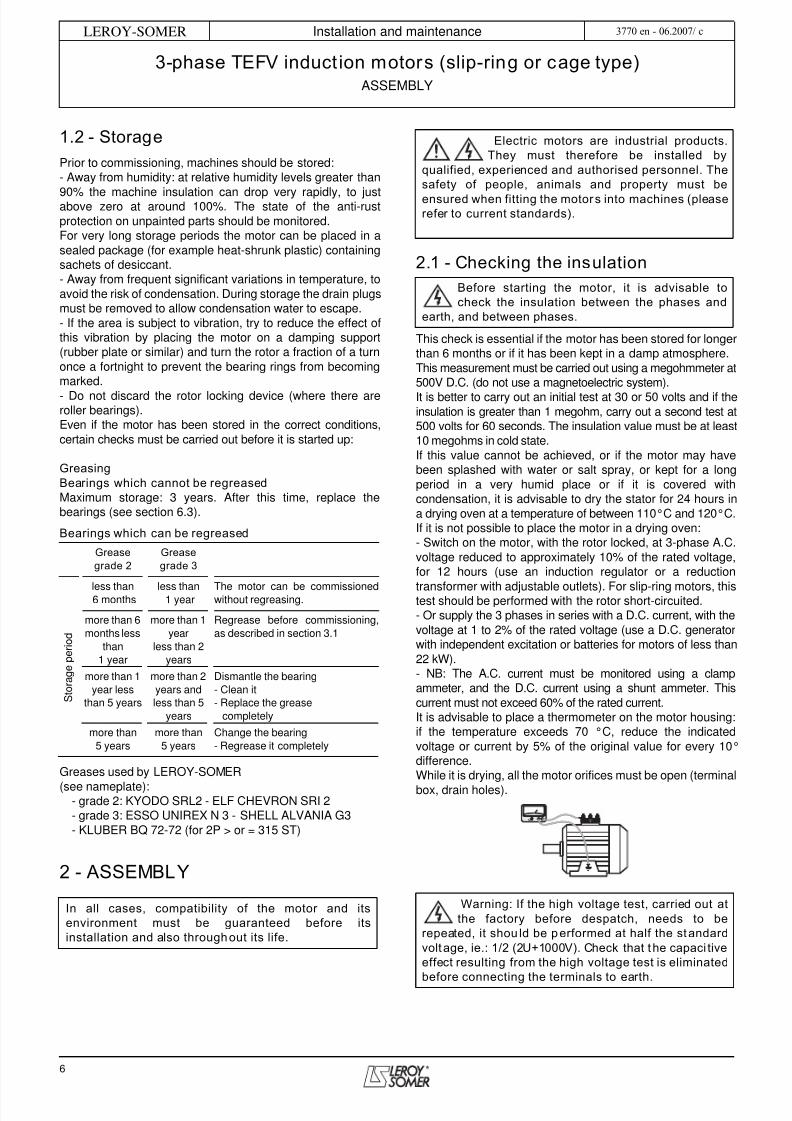
This check is essential if the motor has been stored for longerthan 6 months or if it has been kept in a damp atmosphere.This measurement must be carried out using a megohmmeter at500V D.C. (do not use a magnetoelectric system).It is better to carry out an initial test at 30 or 50 volts and if theinsulation is greater than 1 megohm, carry out a second test at500 volts for 60 seconds. The insulation value must be at least10 megohms in cold state.If this value cannot be achieved, or if the motor may havebeen splashed with water or salt spray, or kept for a longperiod in a very humid place or if it is covered withcondensation, it is advisable to dry the stator for 24 hours ina drying oven at a temperature of between 110°C and 120°C.If it is not possible to place the motor in a drying oven:- Switch on the motor, with the rotor locked, at 3-phase A.C.voltage reduced to approximately 10% of the rated voltage,for 12 hours (use an induction regulator or a reduction
transformer with adjustable outlets). For slip-ring motors, thistest should be performed with the rotor short-circuited.- Or supply the 3 phases in series with a D.C. current, with thevoltage at 1 to 2% of the rated voltage (use a D.C. generatorwith independent excitation or batteries for motors of less than22 kW).- NB: The A.C. current must be monitored using a clampammeter, and the D.C. current using a shunt ammeter. Thiscurrent must not exceed 60% of the rated current.It is advisable to place a thermometer on the motor housing:if the temperature exceeds 70 °C, reduce the indicatedvoltage or current by 5% of the original value for every 10°difference.While it is drying, all the motor orifices must be open (terminalbox, drain holes).
Greasegrade 2
Greasegrade 3
S t o r a g e p e r i o d
less than6 months less than1 year The motor can be commissionedwithout regreasing.
more than 6months less
than1 year
more than 1year
less than 2years
Regrease before commissioning,as described in section 3.1
more than 1year less
than 5 years
more than 2years andless than 5
years
Dismantle the bearing- Clean it- Replace the grease
completely
more than5 years
more than5 years
Change the bearing- Regrease it completely
In all cases, compatibility of the motor and itsenvironment must be guaranteed before itsinstallation and also throughout its life.
Electric motors are industrial products.They must therefore be installed by
qualified, experienced and authorised personnel. Thesafety of people, animals and property must be
ensured when fitting the motors into machines (pleaserefer to current standards).
Before starting the motor, it is advisable tocheck the insulation between the phases and
earth, and between phases.
M
Warning: If the high voltage test, carried out atthe factory before despatch, needs to be
repeated, it should be performed at half the standardvoltage, ie.: 1/2 (2U+1000V). Check that the capacitiveeffect resulting from the high voltage test is eliminated
before connecting the terminals to earth.

5/14/2018 Tefv Motor - slidepdf.com
http://slidepdf.com/reader/full/tefv-motor 7/56
7
INSTALLATION AND MAINTENANCE
3-phase TEFV induction motors (slip-ring or cage type)ASSEMBLY
LEROY-SOMER 3770 en - 06.2007/ c
2.2 - Location - ventilationOur motors are cooled in accordance with method IC 411(standard IEC 34-6), ie. "machine cooled by its surface, usingthe ambient fluid (air) flowing along the machine".The fan at the non drive end cools the motor. Air is sucked inthrough the grille of a fan cover (which provides protectionagainst the risk of direct contact with the fan in accordancewith standard IEC 34-5) and blown along the housing fins toensure thermal equilibrium of the motor whatever thedirection of rotation.
The motor must be installed in an adequately ventilated area,with clearance for the air intake and outlet of at least one-quarter of the frame size.Obstruction (clogging) - even accidental - of the fan covergrille has an adverse effect on motor operation.In the case of vertical operation with the shaft extensionfacing down, it is advisable to fit the motor with a drip cover toprevent penetration by any foreign bodies.It is also necessary to check that the hot air is not beingrecycled. If it is, pipes must be provided for the intake of coldair and the discharge of hot air, in order prevent abnormalmotor temperature rise.In this case, if the air is not circulated by an auxiliary fan, thedimensions of the pipes must be such that the pressurelosses are negligible compared to those of the motor.
PositioningThe motor must be mounted in the position specified onthe order, on a base which is rigid enough to preventdistortion and vibration.Where the motor feet have six fixing holes, it is preferable touse those which correspond to the standard dimensions forthe motor power rating (refer to the technical catalogue forinduction motors), or, failing that, to those shown at B2.
Ensure there is easy access to the terminal box, thecondensation drain plugs and, if appropriate, to the greasenipples.Use lifting equipment which is compatible with the weight ofthe motor (indicated on the nameplate).
2.3 - CouplingPreparationTurn the motor by hand before coupling to detect any possiblefault due to handling.Remove any protection from the shaft extension.
Drain off any condensation water which may have formedinside the motor by removing the plugs from the drain holes.
Rotor locking deviceFor made-to-order motors with roller bearings, remove therotor locking device.In exceptional circumstances when the motor has to bemoved after the coupling device has been fitted, the rotormust be re-immobilised.
BalancingRotating machines are balanced in accordance with standardISO 8821:- Half-key when the shaft extension is marked H
- No key when the shaft extension is marked N.- Full key when the shaft extension is marked F.and any coupling element (pulley, coupling sleeve, slip-ring,etc) must therefore be balanced accordingly.
Motor with 2 shaft extensions:If the second shaft extension is not used, in order tocomply with the balancing class, the key or half-key mustbe fixed firmly in the keyway so that it is not thrown outduring rotation (H or F balancing) and must be protectedagainst direct contact.PrecautionsAll measures must be taken to ensure protection against therisks which arise when there are rotating parts (coupling
sleeve, pulley, belt etc).
Prior to commissioning for all motors:Rotate the motor at no load (no mechanical load)
for 2 to 5 minutes, checking that there is no abnormalnoise. If there is any abnormal noise, see section 5.
1/4 H min
H
B 2B 1
When the motor is fitted with lifting rings, theyare for lifting the motor on its own and must not
be used to lift the whole machine after the motor hasbeen fitted to it.
Note 1: When installing a suspended motor, it isessential to provide protection in case the fixing breaks.Note 2: Never stand on the motor.

5/14/2018 Tefv Motor - slidepdf.com
http://slidepdf.com/reader/full/tefv-motor 8/56
8
Installation and maintenance
3-phase TEFV induction motors (slip-ring or cage type)ASSEMBLY
LEROY-SOMER 3770 en - 06.2007/ c
Beware of backdriving when the motor is switched off. Theappropriate precautions must be taken:- For pumps, a non-return valve must be installed.- For mechanical devices, install a backstop or a holdingbrake.- Etc.
Tolerances and adjustmentsThe standard tolerances are applicable to the mechanicalcharacteristics given in our catalogues. They comply fully with therequirements of IEC standard 72-1.- Users must adhere strictly to the instructions provided by thetransmission device supplier.- Avoid impacts which could damage the bearings.
Use a spanner and the tapped hole of the shaft end with aspecial lubricant (e.g. molykote grease) to make it easier to fitthe coupling.
The hub of the transmission device must be:- Fully in contact with the shoulder of the shaft or, if this ismissing, against the metal stop ring which forms a labyrinth
seal and thus locks the bearing in place (do not crush theseal).- Longer than the shaft extension (2 to 3 mm) so that it can betightened using a screw and washer. If it is not, a spacer ringmust be inserted without cutting the key (if this ring is large, itmust be balanced).
If there is a second shaft extension, it must only be used fordirect coupling and the same recommendations must befollowed.
The inertia flywheels device must not be mounted directlyonto the shaft extension, but installed between end shield anddevice using a coupling.
Mounting a face mounted motorMounting face mounted motors IM B14 (IM 3601) and IM B34(IM 2101).Max. screw insertion length when mounting face mountedmotors IM B34 and IM B14.
Direct connection onto the machineWhen the mobile device (pump or fan turbine) is mounteddirectly on the motor shaft extension, check that this device isperfectly balanced and that the radial force and the axialthrust are within the limits indicated in the catalogue for thebearing withstand.Direct connection using a flexible coupling
Selection of the coupling sleeve should take account of therated torque to be transmitted and the safety factordependent on the starting conditions for the electric motor.The machines must be carefully aligned, so that any lack ofconcentricity and parallelism in the two coupling halves iscompatible with the recommendations of the coupling sleevemanufacturer.Both parts of the coupling should be provisionally assembledto make it easier to alter their relative position.Adjust the parallel plane of both shafts using a gauge.Measure the distance between the two coupling surfaces atone point on the circumference. Rotate them 90°, 180° and270°in relation to this initial position, and measure each time.The difference between the two extremes of the value "x"must not exceed 0.05 mm for standard couplings.
To perfect this adjustment and at the same time check theconcentricity of the two shafts, fit 2 gauges as shown in thediagram and slowly turn both shafts.
The deviations registered by either shaft will indicate the needfor either an axial or radial adjustment if the deviation exceeds0.05mm.
Direct connection using a rigid couplingBoth shafts must be aligned so as to adhere to the tolerancesof the coupling sleeve manufacturer.Maintain the minimum distance between the two shaftextensions to allow for expansion of the motor shaft and theload shaft.
If a motor is started up without a coupling devicehaving been fitted, carefully immobilise the key in
its location.
Appliedto shoulder of shaft Appliedto stop ring
The 2nd shaft extension may also be smaller thanthe main shaft extension, and under no
circumstances can it deliver torques greater than halfthe rated torque.
Max. insertion (mm)
LS 56 F65 M5 11LS 63 F75 M5 / F85 M6 15LS 71 F75 M5 / F85 M6 13
LS 80 F100 M6 11LS 90 F115 M8 11LS 100 F130 M8 11LS 112 F130 M8 11LS 132 F215 M12 11LS 160 F215 M12 15
x
A
Ø
Ø (mm) A (mm)min.
9 to 55 160 1.5
65 1.575 280 2

5/14/2018 Tefv Motor - slidepdf.com
http://slidepdf.com/reader/full/tefv-motor 9/56
9
INSTALLATION AND MAINTENANCE
3-phase TEFV induction motors (slip-ring or cage type)ASSEMBLY
LEROY-SOMER 3770 en - 06.2007/ c
Transmission via belt pulleysThe user can choose the diameter of the pulleys.Cast iron pulleys with a diameter greater than 315 are notrecommended for rotation speeds of 3000 min-1.
Flat belts cannot be used for rotation speeds of 3000 min-1
ormore.
Positioning the beltsSo that the belts can be correctly positioned, allow forpossible adjustment of approximately 3% with respect to thecalculated distance E.Force must never be used when fitting the belts.For notched belts, position the notches in the pulley grooves.
Aligning the pulleysCheck that the motor shaft is completely parallel with that ofthe receiving pulley.
Adjusting the tension of the beltsThe tension of the belts must be adjusted very carefully inaccordance with the recommendations of the belt supplierand the calculations made when the product was specified.
Reminder:- Tension too great = unnecessary force on the end shieldswhich could lead to premature wear of the bearing unit (endshield-bearings) and eventually break the shaft.- Too little tension = vibration (wearing of the bearing unit).Fixed distance between centres:Place a belt tensioning pulley on the slack side of the belts:- Smooth pulley on the outside of the belt- Grooved pulley on the inside of the belts when using V-belts.Adjustable distance between centres:The motor is usually mounted on slide rails, which enablesoptimum adjustment of the pulley alignment and the belttension.Place the slide rails on a perfectly horizontal baseplate.The lengthways position of the slide rails is determined by thelength of the belt, and the crossways position by the pulley ofthe machine being driven.Mount the slide rails firmly with the tension screws in thedirection shown in the diagram (the slide rail screw on the beltside between the motor and the machine being driven).Fix the slide rails onto the baseplate and adjust the belttension as before.
Optional: Standard slide rails (conforming to standard NFC 51-105) These steel slide rails are supplied with tension screws and the 4 nuts and bolts for fixing the motor on the slide rails, but the fixingbolts for the slide rails are not supplied.
E
Protect all rotating devices before power-up.
Tension screw
Tension screw
Motor Type Dimensions Weight per pairframe size of slide rail A E H K L X Y Z Ø J of slide rails (kg)80 and 90 G 90/8 PM 355 395 40 2.5 50 324 264 294 13 3
100, 112 and 132 G 132/10 PM 480 530 49.5 7 60 442 368 405 15 6160 and 180 G 180/12 PM 630 686 60.5 7 75 575 475 525 19 11
200 and 225 G 225/16 PF 800 864 75 28.5 90 - 623 698 24 16250 and 280 G 280/20 PF 1000 1072 100 35 112 - 764 864 30 36315 and 355 G 355/24 PF 1250 1330 125 36 130 - 946 1064 30 60
H
L
Y
Z
X
A
E
K
ØJ

5/14/2018 Tefv Motor - slidepdf.com
http://slidepdf.com/reader/full/tefv-motor 10/56
10
Installation and maintenance
3-phase TEFV induction motors (slip-ring or cage type)ASSEMBLY
LEROY-SOMER 3770 en - 06.2007/ c
2.4 - Electrical guidelines
2.4.1 - Maximum power of motors supplieddirectly (kW) from the mains
This extract from standard NFC 15-100 indicates the limitstolerated for D.O.L. starting of a motor connected to the mainspower supply.
* "Other locations" include premises such as those in the service
sector, the industrial sector, general housing services, the agricultural
sector, etc.
Prior inspection by the power supply company is necessary for
motors driving a high inertia machine, motors with time-delay starting
and brake motors or reversers using reverse current.
2.4.2 - Limiting problems caused by motorstarting
In order to protect the installation, all significant temperaturerises in the cabling conduits must be prevented, whileensuring that the protection devices are not triggered duringstarting.
Operating problems in other equipment connected to thesame supply are due to the voltage drop caused by thecurrent demand on starting - many times greater than thecurrent absorbed by the motor at full load (approximately 7).See the LEROY-SOMER induction motors technicalcatalogue).Even though the mains supplies increasingly allow D.O.L.starting, the current inrush must be reduced for certaininstallations.Jolt-free operation and soft starting ensure greater ease ofuse and an increased lifespan for the machines being driven.The two essential parameters for starting cage inductionmotors are:
- starting torque- starting currentThe starting torque and the resistive torque determine thestarting time.Depending on the load being driven, it may be necessary toadapt the torque and the current to the machine starting timeand to the possibilities of the mains power supply.The five essential modes are:- D.O.L. starting- Star/delta starting- Soft starting with autotransformer- Soft starting with resistors- Electronic starting
The "electronic" starting modes control the voltage at themotor terminals during the entire starting phase and enablevery soft, jolt-free starting.
2.4.3 - LEROY-SOMER "Digistart" electronicstarter
This is a multi-function electronic system with amicrocontroller, which is used with all 3-phase cage inductionmotors.It provides soft starting of the motor with:- Reduction of the starting current- Gradual, jolt-free acceleration, achieved by controlling thecurrent absorbed by the motor.After starting, the DIGISTART performs additional motorcontrol functions in its other operating phases: steady stateand deceleration.- 9 to 500 kW models
- Supply: 220 to 700 V - 50/60 HzDIGISTART is economical to install, as a fused switch is theonly additional device needed.
2.4.4 - Other control systems
Frequency inverters, flux vector control, etc. Specialprecautions need to be taken when standard induction motorsare being used for variable speed control, powered by afrequency inverter or voltage controller:
During prolonged operation at low speed, cooling efficiency isgreatly diminished. It is therefore advisable to install a forcedventilation unit that will produce a constant flow of airindependently of the motor speed.In prolonged operation at high speed, the fan may makeexcessive noise. It is again advisable to install a forcedventilation system.
Type of motorSingle phase230 (220) V
3-phase400 (380) V
Type of premisesD.O.L. starting Other starting
modes
Residential areas 1.4 5.5 11
Other locations*
Overhead power 3 11 22
Underground 5.5 22 45
The reference voltage (drive output or motorinput) is 400V at 50 Hz: The drive must deliver a
constant voltage/frequency signal to the motor in the50 Hz operating range. Beyond the 25/50 Hz range,ensure that the fan and bearing unit are suitable.
1/3
2/3
1
0 1/3 2/3 1
N / Ns
Forced ventilation(temperature rise)
Natural cooling Forced ventilationfor N > 3600 min-1
Operating speed/Synchronous speed
Effect of cooling
P/PN = f (N/NS)

5/14/2018 Tefv Motor - slidepdf.com
http://slidepdf.com/reader/full/tefv-motor 11/56
11
INSTALLATION AND MAINTENANCE
3-phase TEFV induction motors (slip-ring or cage type)ASSEMBLY
LEROY-SOMER 3770 en - 06.2007/ c
If the frequency exceeds 50 Hz:a - Carefully check that all the components on a particulartransmission are properly aligned.b - The voltage remains constant above 50 Hz.
c - The power supplied by the motor up to 60 Hz remainsconstant (make sure that the power absorbed by the loaddoes not vary differently in this frequency range).d - Check that the application speed does not exceed thespeed values indicated in the table below:
* Above these limits, motors have to be specially designed.
e - For all other frequency and/or voltage limits, additional
precautions must be taken for derating, bearings, ventilation,noise, etc: please consult Leroy-Somer.
2.4.5 - Permissible starting times and lockedrotor timesThe starting times must remain within the limits stated belowon condition that the number of starts per hour is 6 or less.Three successive cold starts and two consecutive warmstarts are allowed.
Permissible motor starting time in relation to the ratio I D /I N for
cold starts.
2.4.6 - Earthing (see section 2.5.5)
2.4.7 - Starting slip-ring motors
For a motor with wound slip-ring rotor, place the startingdevice (electrolytic starter, rheostat, etc) as close as possibleto the motor and use cables with the largest possiblecross-section.Any thermal protection devices or space heaters areconnected in the terminal box.
2.4.8 - Power factor compensation capacitors
2.4.9 - Motor protection devices
2.4.9.1 - On-line protection
Adjusting the thermal protection It should be adjusted to the value of the current read on the
motor nameplate for the connected mains voltage andfrequency.
Thermal magnetic protectionThe motors must be protected by a thermal magnetic devicelocated between the isolating switch and the motor. Theseprotection devices provide total protection of the motoragainst non-transient overloads.This device can be accompanied by fused circuit-breakers.
Built-in direct thermal protectionFor low rated currents, bimetallic strip-type protection may beused. The line current passes through the strip, which shutsdown or restores the supply circuit as necessary. The design
of this type of protection allows for manual or automatic reset.
2.4.9.2 - Built-in indirect thermal protectionThe motors can be equipped with optional heat sensors.These sensors can be used to monitor temperature changesat “hot spots”:- overload detection- cooling check- Monitoring strategic points for maintenance of theinstallationIt must be emphasized that these sensors cannot be used tocarry out direct adjustments to the motor operating cycles.
Frame sizeSpeed of rotation min-1
2 poles 4 poles 6 poles
56* 4500 4500 450063* 4500 4500 450071* 4500 4500 450080 15000 15000 1500090 12000 12000 12000
100 10000 10000 10000112 10000 10000 10000132 7500 7500 7500160 6000 6000 6000180 5600 5600 5600200 4500 4500 4500225 4100 4100 4100250 4100 4100 4100280 3600 3600 3600315 3600 3000 3000355 3600 3000 3000
3 4 5 7 10 153
4
5
6
7
8
9
10
15
20
I D _I N
St
For details of the various starting devices(eg: rheostats, LS Polystart), see the relevant
installation and maintenance manuals.
Before any work is carried out on the motor or inthe cabinet, check that the capacitors are
isolated and/or discharged (read the voltage at theterminals).

5/14/2018 Tefv Motor - slidepdf.com
http://slidepdf.com/reader/full/tefv-motor 12/56
12
Installation and maintenance
3-phase TEFV induction motors (slip-ring or cage type)ASSEMBLY
LEROY-SOMER 3770 en - 06.2007/ c
- NRT: nominal running temperature- The NRTs are chosen according to the position of the sensor in the motor and the temperature rise class.* The number of devices affects the protection of the windings.
Alarm and early warningAll protective equipment can be backed up by another type ofprotection (with different NRTs): The first device will then actas an early warning (light or sound signals given withoutshutting down the power circuits), and the second device willbe the alarm (shutting down the power circuits).
Protection against condensation: space heatersIdentification: 1 red labelA glass fibre flexible resistor is fixed on 1 or 2 coil end turns.This resistor heats the machines when stopped and thusprevents condensation inside the machines.Power supply: 230V single-phase unless otherwise specifiedby the customer.
If the drain plugs at the bottom of the motor have not beenremoved at the time of installation, they must be openedapproximately every 6 months.
Type Operatingprinciple
Operatingcurve
Breakingcapacity (A)
Protection provided MountingNumber required*
Normally closedthermostat
PTO
bimetallic strip,indirectly heatedoperates on opening (O) 2.5 at 250 V
with cos ϕ 0.4general surveillance
for non-transientoverloads
Mounted on controlcircuit
2 or 3 in series
Normally openthermostat
PTF
bimetallic strip, indirectlyheated,
contact on closing (F) 2.5 at 250 Vwith cos ϕ 0.4
general surveillancefor non-transient
overloads
Mounted on controlcircuit
2 or 3 in parallel
Positive temperaturecoefficient thermistor
PTC
Variable non-linearresistor, indirectly
heated 0 general surveillance
for transient overloads
Mounted with associatedrelay on control circuit
3 in series
Thermocouples T (T<150 °C)
Constantan copperK (T<1000 °C)Copper-Nickel
Peltier effect 0Continuous surveillanceat hot spots at regular
intervals
Mounted on controlpanels with associated
reading device(or recording device)
1 per hot spot
Platinum resistancethermometer
PT 100
Variable linearresistance,
indirectly heated0
high accuracyContinuous surveillance
at key hot spots
Mounted on controlpanels with associated
reading device(or recording device)
1 per hot spot
I
O TNF
T
I
F TNF
T
R
TNF
T
V
T
R
T
Warning: Depending on the type of protection,the motor may remain powered-up. Ensure thatthe mains supply is disconnected before any work iscarried out in the terminal box or in the cabinet.
Warning: Check that the space heaters arepowered down before any work is carried out in
the terminal box or in the cabinet.
5/14/2018 Tefv Motor - slidepdf.com
http://slidepdf.com/reader/full/tefv-motor 13/56
13
INSTALLATION AND MAINTENANCE
3-phase TEFV induction motors (slip-ring or cage type)ASSEMBLY
LEROY-SOMER 3770 en - 06.2007/ c
2.5 - Mains connection
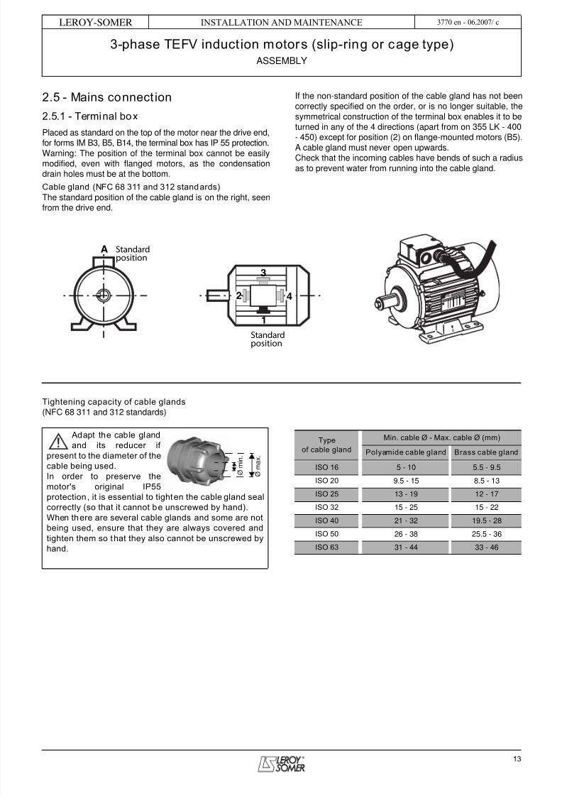
2.5.1 - Terminal box
Placed as standard on the top of the motor near the drive end,for forms IM B3, B5, B14, the terminal box has IP 55 protection.Warning: The position of the terminal box cannot be easilymodified, even with flanged motors, as the condensationdrain holes must be at the bottom.
Cable gland (NFC 68 311 and 312 standards)The standard position of the cable gland is on the right, seenfrom the drive end.
If the non-standard position of the cable gland has not beencorrectly specified on the order, or is no longer suitable, thesymmetrical construction of the terminal box enables it to beturned in any of the 4 directions (apart from on 355 LK - 400
- 450) except for position (2) on flange-mounted motors (B5).A cable gland must never open upwards.Check that the incoming cables have bends of such a radiusas to prevent water from running into the cable gland.
Tightening capacity of cable glands(NFC 68 311 and 312 standards)
A Standardposition
Standardposition
2 4
1
3
Adapt the cable glandand its reducer if
present to the diameter of thecable being used.In order to preserve themotor's original IP55protection, it is essential to tighten the cable gland sealcorrectly (so that it cannot be unscrewed by hand).When there are several cable glands and some are notbeing used, ensure that they are always covered andtighten them so that they also cannot be unscrewed byhand.
Ø m
a x .
Ø m
i n .
Typeof cable gland
Min. cable Ø - Max. cable Ø (mm)
Polyamide cable gland Brass cable gland
ISO 16 5 - 10 5.5 - 9.5
ISO 20 9.5 - 15 8.5 - 13
ISO 25 13 - 19 12 - 17
ISO 32 15 - 25 15 - 22
ISO 40 21 - 32 19.5 - 28
ISO 50 26 - 38 25.5 - 36
ISO 63 31 - 44 33 - 46

5/14/2018 Tefv Motor - slidepdf.com
http://slidepdf.com/reader/full/tefv-motor 14/56
14
Installation and maintenance
3-phase TEFV induction motors (slip-ring or cage type)ASSEMBLY
LEROY-SOMER 3770 en - 06.2007/ c
2.5.2 - Cross-section of the power supplycables
The higher the current, the greater the voltage drop in the
cables (standard NFC 15.100 or end user's nationalstandard). The voltage drop should therefore be calculatedfor the starting current to see if this is suitable for theapplication.
If the most important criterion is the starting torque (or startingtime), the voltage drop should be limited to 3% maximum (theequivalent of a loss of torque of around 6 to 8%).The chart below can be used to select the conductors
according to the length of the supply cables and the startingcurrent, in order to limit the voltage drop to 3% maximum.
1 2 3 4 5 6 7 8 9 10 2 3 4 5 6 7 8 9 100 2 3 4 5 2 3 4 56 7 8 9 100010
20
30
40
50
60
708090
100
200
300
400
500
600
700800900
1000
Length in m Maximum voltage drop 3 % (3-phase circuits - copper cable)
Current in ampsStarting current
1 1.5 2.5 4 6 10 16 35 50 75 9025 Conductor cross-section
For motors with flying leads, the power supply cable must not be used for handling.

5/14/2018 Tefv Motor - slidepdf.com
http://slidepdf.com/reader/full/tefv-motor 15/56
15
INSTALLATION AND MAINTENANCE
3-phase TEFV induction motors (slip-ring or cage type)ASSEMBLY
LEROY-SOMER 3770 en - 06.2007/ c
2.5.3 - Terminal block wiring diagram
All motors are supplied with a wiring diagram in the terminalbox*.The connector links required for coupling can be found insidethe terminal box.Single-speed motors are fitted with a block of 6 terminalscomplying with standard NFC 51 120, with the terminalmarkings complying with IEC 34 - 8 (or NFC 51 118).
2.5.4 - Direction of rotation
When the motor is powered by U1, V1, W1 or 1U, 1V, 1W
from a direct mains supply L1, L2, L3, it turns clockwise whenseen from the drive end.If 2 phases of the power supply are changed over, the motorwill run in an anti-clockwise direction (make sure the motorhas been designed to run in both directions of rotation).Warning: motor with backstop: starting in the wrong directiondestroys the backstop (see arrow on motor housing).If the motor is fitted with accessories (thermal protection orspace heater), these should be connected on screw dominosor terminal blocks with labelled wires (see section 2.4).
2.5.5 - Earth terminal
This is situated inside the terminal box; in some cases, theearth terminal may be situated on one of the feet or on one of
the cooling fins (round motors).It is indicated by the symbol:
* If required, this diagram should be obtained from thesupplier, specifying the motor type and number (shown on themotor nameplate).
2.5.6 - Connecting the power supply cables tothe terminal block
The cables must be fitted with connectors suitable for the
cable cross-section and the terminal diameter.They must be crimped in accordance with the connectorsupplier's instructions.Connection must be carried out with connector resting onconnector (see the diagrams below):
Tightening torque (N.m) on the terminal block nuts
If using cables without connectors, attach some calipers.If any nuts on the brass terminal block are lost, they must bereplaced by brass nuts, not steel ones.When closing the box, ensure that the seal is correctlypositioned.
Particular attention must be paid to theinformation on the nameplate in order to choose
the correct type of connection for the supply voltage.
Temperature probe
It is compulsory to earth the motor. Earthingmust be performed in accordance with current
regulations (protection of workers).
Terminal M4 M5 M6 M8 M10 M12 M14 M16
Steel 2 3.2 5 10 20 35 50 65
Brass 1 2 3 6 12 20 - 50
As a general rule, check that no nut, washer orother foreign body has fallen into or come into
contact with the winding.

5/14/2018 Tefv Motor - slidepdf.com
http://slidepdf.com/reader/full/tefv-motor 16/56
16
Installation and maintenance
3-phase TEFV induction motors (slip-ring or cage type)ROUTINE MAINTENANCE
LEROY-SOMER 3770 en - 06.2007/ c
3 - ROUTINE MAINTENANCEChecks after start-upAfter approximately 50 hours' operation, check that the
screws fixing the motor and the coupling device are still tight.In the case of chain or belt transmission, check that thetension is correctly adjusted.
CleaningTo ensure the motor operates correctly, remove any dust orforeign bodies which might clog the cover grille and thehousing fins.Precaution: before carrying out any cleaning operation checkthat the motor is completely sealed (terminal box, drain holes,etc).Dry cleaning (vacuuming or compressed air) is alwayspreferable to wet cleaning.
Draining off condensation waterTemperature variations cause condensation to form insidethe motor, which must be removed before it adversely affectsmotor operation.Condensation drain holes, located at the bottom of the motors(bearing in mind their operating position) are sealed withplugs which must be removed and then replaced every sixmonths (if they were not replaced, the motor degree of
protection would no longer be maintained). Clean the orificesand plugs before reassembling them.Note: In conditions of high humidity and significanttemperature variations, a shorter period is recommended.As long as it poses no risk to the motor protection, thecondensation drain plugs can be removed.
3.1 - Greasing
3.1.1 - Type of grease
When the bearings are not greased for life, the type of greaseis indicated on the nameplate.
As standard this grease is ESSO UNIREX N3 and werecommend that it is used for subsequent lubrication. Avoidmixing greases.
3.1.2 - Permanently greased bearings
For LS motors < or = 180 MT and FLS(C) < or = 132 M, thebearings defined offer long grease life and thereforelubrication for the lifetime of the machines. The grease lifeaccording to speed of rotation and ambient temperature isshown on the chart below.
3.1.3 - Bearings without grease nipples
LS 180 L and LS 200 LT motors are lubricated in the factory.Lubricant lifetime under normal operating conditions is givenin the table below for a machine with horizontal shaftoperating at 50 Hz in ambient temperatures of 25°C and40°C.
3.1.4 - Bearings with grease nipples
The bearings are lubricated in the factoryFor LS motors of type 200 LT (or on request for types 160,180, 200 LT) and for FLS(C) and FLSB motors of type 160 orabove, the end shields are fitted with bearings lubricated bygrease nipples such as Tecalemit-Hydraulic M8 x 125.
Always clean at reduced pressure from thecentre of the motor towards the extremities to
avoid introducing dust and particles under the seals.
Polarity T amb. Frame size Frame size
2 p40 °C 11,000 9,00025 °C 22,000 18,000
4 p40 °C 23,000 20,000
25 °C 45,000 40,000
6 p40 °C 28,000 26,00025 °C 45,000 45,000
8 p40 °C 33,000 31,00025 °C 45,000 45,000
10
0
20
30
40
50
60
Amb T (°C)
3010 20
N = 750 min -1
N = 1500 min -1
N = 1000 min -1
5 15 25
N = 3000 min -1
Life in 000’s of hours
The frequency of lubrication and the quantity andquality of grease are given on the nameplates
and these should be referred to in order to ensurecorrect bearing lubrication.
Even in the event of prolonged storage ordowntime, the interval between 2 greasing
operations should never exceed 2 years.

5/14/2018 Tefv Motor - slidepdf.com
http://slidepdf.com/reader/full/tefv-motor 17/56
17
INSTALLATION AND MAINTENANCE
3-phase TEFV induction motors (slip-ring or cage type)ROUTINE MAINTENANCE
LEROY-SOMER 3770 en - 06.2007/ c
3.2 - Bearing maintenance
3.2.1 - Checking the bearings
As soon as you detect any of the following on the motor:- Abnormal noise or vibration- Abnormal temperature rise in the bearing even though it hasbeen lubricated correctlythe condition of the bearings must be checked.Damaged bearings must be replaced as soon as possibleto prevent worse damage to the motor and the equipmentbeing driven.If one bearing needs to be replaced, the other bearing mustalso be replaced.The seals should be changed routinely when the bearingsare changed.The free bearing must allow the rotor shaft to expand (checkits identification during dismantling).
3.2.2 - Reconditioning the bearings
Bearings without grease nipplesDismantle the motor (see section 6.1); remove the old greaseand clean the bearings and accessories with degreasingagent.Fill with new grease: the correct amount of new grease for thebearing is 50% of the free space.
Bearings with grease nipplesAlways begin by cleaning the waste grease channel If using the type of grease stated on the nameplate, remove
the covers and clean the grease nipple heads.If a different grease from that on the nameplate is being used,the motor must be dismantled and the bearings andaccessories cleaned with degreasing agent (carefully cleanthe grease inlet and outlet pipes) to remove the old greasebefore relubrication.To ensure correct lubrication, fill the inner free spaces of thebearing retainers, flanges and grease pipes and 30% of thebearing free space.Then rotate the motor shaft to distribute the grease.
Warning:Too much grease causes the bearing to overheat (statistics
show that more bearings are damaged through too muchgrease than too little grease).
Important note:The new grease should be recently manufactured, ofequivalent performance and should not contain any impurities(dust, water, etc).
3.3 - Slip-ring motorsMaintenance of brushes and slip-ringsOn slip-ring motors, check the state of the commutator
monthly. The slip-rings must be clean, non-greasy, smoothand without surface roughness. If the commutator is dirty,clean it with a petrol-soaked rag.Check that the brushes:- Slide freely in their cage- Are seated uniformly on the slip-rings- Show no signs of wear as far as the shuntIf there is too much wear, replace them with new brushes ofthe same number and quality as the original ones and grindthe contact surface. To do this:- Roughen the bend before inserting the brushes in the brushholders- Continue with a piece of fine emery cloth wound round theslip-rings
- Finish with a piece of very fine sandpaper, rubbing in thenormal direction of rotationAfter grinding, check that there are no abrasive particles onthe brush surfaces and clean them with extreme care.We also strongly recommend blowing frequently inside themachine with a blast of compressed dry air to clear out anycoal dust from the shields, brush holders, commutator,commutator terminals and windings.The insulating components should be wiped with a cleancloth.Motor which is rotating: Ensure that there are no sparks underthe brushes.

5/14/2018 Tefv Motor - slidepdf.com
http://slidepdf.com/reader/full/tefv-motor 18/56
18
Installation and maintenance
3-phase TEFV induction motors (slip-ring or cage type)PREVENTIVE MAINTENANCE
LEROY-SOMER 3770 en - 06.2007/ c
4 - PREVENTIVE MAINTENANCEPlease consult LEROY-SOMER who, in its continuous searchfor ways to help customers, has evaluated numerous
methods of preventive maintenance.The diagram and table below give the recommendedequipment to use and the ideal positions to takemeasurements of all parameterswhich can affect the operation ofthe machine,such as eccentricity, vibration, state of bearings, structuralproblems, electrical problems, etc.
M 01V M 02V
M 02A
M 02HM 01H
1
3
4
2
5
Detector MeasurementMeasurement points
M 01V M 01H M 02V M 02H M 02A Shaft E01 E02 E03
¿ Accelerometer For measuring vibrations • • • • •¡ Photo-electric cell For measuring speed and phase •¬ Clamp ammeter For measuring current (D.C. and 3-phase • • •Ð Voltage probe A.C. and D.C. voltages • • •ƒ Infra-red probe For measuring temperature • •

5/14/2018 Tefv Motor - slidepdf.com
http://slidepdf.com/reader/full/tefv-motor 19/56
19
INSTALLATION AND MAINTENANCE
3-phase TEFV induction motors (slip-ring or cage type)TROUBLESHOOTING GUIDE
LEROY-SOMER 3770 en - 06.2007/ c
5 - TROUBLESHOOTING GUIDEIncident Possible cause Remedy
Abnormal noise Originating in motor or machine being driven? Uncouple the motor from the equipment being driven
and test the motor on its own
Noisy motor Mechanical cause: if the noise persists afterswitching off the electrical power supply
- Vibration - Check that the key conforms to the type of balancing(see section 2.3)
- Damaged bearings - Change the bearings
- Mechanical friction: ventilationcoupling
- Check
Electrical cause: if the noise stops after switching offthe power supply
- Check the power supply at the motor terminals
- Normal voltage and 3 phases balanced - Check the connection of the terminal block and the
tightening of the connectors- Abnormal voltage - Check the power supply line
- Phase imbalance - Check the winding resistance
Motor heatsabnormally
- Faulty ventilation - Check the environment- Clean the fan cover and the cooling fins- Check that the fan is correctly mounted on the shaft
- Faulty supply voltage - Check
- Terminal connection fault - Check
- Overload - Check the current consumption in relation to thatindicated on the motor nameplate
- Partial short-circuit - Check the electrical continuity of the windings and/orthe installation
- Phase imbalance - Check the winding resistance
Motor does not start No load- Mechanical seizing- Supply line disconnected
When switched off:- Check by hand that the shaft rotates freely- Check the fuses, electrical protection, starting device
On load- Phase imbalance
When switched off:- Check the direction of rotation (phase order)- Check the resistance and continuityof the windings- Check the electrical protection
Slip-ring motors- Rotor circuit open - Connect the rotor to the starting device

5/14/2018 Tefv Motor - slidepdf.com
http://slidepdf.com/reader/full/tefv-motor 20/56
20
Installation and maintenance
3-phase TEFV induction motors (slip-ring or cage type)CORRECTIVE MAINTENANCE: GENERAL
LEROY-SOMER 3770 en - 06.2007/ c
6 - CORRECTIVE MAINTENANCE:GENERAL
- Open the terminal box, mark the wires and their positions- Disconnect the power supply wires- Uncouple the motor from the equipment being drivenAlways use an extractor to remove any devices mounted onthe shaft end of the motor.
6.1 - Dismantling the motorRefer to the detailed instructions for the relevant motor range(see following pages).It is advisable to mark the shields in relation to the stator andthe direction in which the rotor fan is mounted.
6.2 - Checks before reassemblyStator:- Remove all dust from the stator:If the winding needs to be cleaned, a suitable liquid must beused: dielectric and inert on the insulating components andthe external finish.- Check the insulation (see section 2.1) and if necessary, dryit in an oven.- Clean the spigots thoroughly, and remove all traces ofknocks on the mating surfaces if necessary.Rotor:- Clean and check the bearing running surfaces. If they aredamaged, renew the running surfaces or change the rotor.- Check the condition of the threads, keys and their housings.End shields:- Clean off any traces of dirt (old grease, accumulated dust,etc).- Clean the bearing housings and the spigot.
- If necessary, apply anti-flash varnish to the insides of theend shields.- Carefully clean the bearing retainers and the grease valves(if these are fitted on the motor).
6.3 - Mounting the bearings on the shaftThis operation is extremely important, as the slightestindentation of a ball on the bearing tracks would cause noiseand vibration.Lightly lubricate the running surfaces of the shaft.There are a number of ways of mounting the bearingscorrectly:- Cold state: The bearings must be mounted without anyimpact, using a spanner (do not use a hammer). The force
applied must not be transferred to the bearing track. Youshould therefore use the internal cage for support (taking carenot to press on the seal shield for sealed bearings).
- Hot state: Heat the bearing to between 80 and 100 °C: in adryer, an oven or on a heating plate.(A blowtorch or an oil bath must never be used).After dismantling and reassembling a bearing, all the spaces
between the seals and labyrinth seals must be filled withgrease in order to prevent the entry of dust and the rusting ofmachined parts.See detailed instructions for the relevant motor ranges in thefollowing pages.
6.4 - Reassembling the motorBe careful to replace the stator in its original position, sothat the stack of laminations is centred correctly (generallywith the terminal box facing forward) and the water drainholes are positioned correctly if they are on the housing.Tightening the tie rodsThese must be tightened diagonally, to the torque indicated(see below).
6.5 - Reassembling the terminal boxReconnect all the power supply wires in accordance with thediagram or markings made before dismantling.To ensure the box is properly sealed: check that the cableglands on the box and the cable(s) have been retightened,and ensure that the seal has been correctly positioned beforeclosing. For terminal boxes equipped with a horn (part no. 89on the exploded views) or/and a cable gland support plate,ensure that the seal has been correctly positioned beforeclosing. Check that the terminal box components aretightened correctly.
Note: It is advisable to test the motor at no load- If necessary, repaint the motor.- Mount the transmission device on the motor shaft extensionand reinstall the motor on the machine to be driven.
First switch off and lock the power supply.
Tie rod tightening torque
Type Rod/screw Ø Tightening torqueN. m ± 5%
56 M4 2.563 M4 2.571 M4 2.580 M5 4
90 M5 4100 M5 or M6 4112 M5 or M6 4132 M7 10160 M8 18180 MT/LR M8 18180 L M10 25200 M10 25225 ST/MR M10 25225 MK M12 44250 M12 44280 M12 44315 M12 44315 LK/355 M16 100355 LK/400 M16 100
450 M16 100
1 4
3 2

5/14/2018 Tefv Motor - slidepdf.com
http://slidepdf.com/reader/full/tefv-motor 21/56
21
INSTALLATION AND MAINTENANCE
3-phase TEFV induction motors (slip-ring or cage type)POSITION OF LIFTING RINGS
LEROY-SOMER 3770 en - 06.2007/ c
7 - POSITION OF LIFTING RINGS
Labour regulations stipulate that all loads over 25 kg must befitted with lifting devices to facilitate handling.The positions of the lifting rings and the minimum dimensionsof the loading bars are given below in order to help withpreparation for handling the motors. If these precautions arenot followed, there is a risk of warping or crushing someequipment such as the terminal box, protective cover or dripcover.
• Horizontal position
• Vertical position
* If the motor is fitted with a drip cover, allow an additional 50 to
100 mm to avoid damaging it when the load is swung.
Type Horizontal positionA e min h min Øt100 120 200 150 9112 120 200 150 9132 160 200 150 9160 200 160 110 14
180 MR 200 160 110 14180 L 200 260 150 14200 270 260 165 14
225 ST/MT 270 260 150 14225 M 360 265 200 30
250 360 380 200 30280 360 380 500 30
315 ST 310 380 500 17315 M/L 360 380 500 23
355 310 380 500 23400 735 710 500 30450 730 710 500 30
Position of lifting rings for lifting the motor only(not connected to the machine)
Motors intended for use in the vertical positionmay be delivered on a pallet in the horizontal
position. When the motor is pivoted, the shaft mustunder no circumstances be allowed to touch the
ground, as the bearings may be irreparably damaged.Moreover, additional special precautions must betaken, as the integral motor lifting rings are notdesigned for pivoting the motor.
e
A
h
2 x Øt
TypeVertical position
C E D n ØS e min* h min
160 320 200 230 2 14 320 350180 MR 320 200 230 2 14 320 270180 L 390 265 290 2 14 390 320200 410 300 295 2 14 410 450
225 ST/MT 410 300 295 2 14 410 450225 M 480 360 405 4 30 540 350250 480 360 405 4 30 540 350
280 S 480 360 485 4 30 590 550280 M 480 360 585 4 30 590 550315 ST 590 - 590 2 17 630 550315 M/L 695 - 765 2 24 695 550
355 755 - 835 2 24 755 550400 810 350 1135 4 30 810 600450 960 400 1170 4 30 960 750
e
h
n x ØS
D
E
C
View from above Side view

5/14/2018 Tefv Motor - slidepdf.com
http://slidepdf.com/reader/full/tefv-motor 22/56
22
Installation and maintenance
3-phase TEFV induction motors (slip-ring or cage type)SPARE PARTS
LEROY-SOMER 3770 en - 06.2007/ c
8 - SPARE PARTSWhen ordering spare parts, you must indicate thecomplete motor type, its serial number and theinformation given on the nameplate (see section 1).
Part numbers can be found on the exploded views andtheir descriptions in the parts list (section 6).
In the case of flange mounted motors, indicate the type offlange and its dimensions (see below).
Our extensive network of service centres can dispatchthe necessary parts without delay.
To ensure that our motors operate correctly and safely,
we recommend the use of original manufacturer spareparts.
In the event of failure to comply with this advice, themanufacturer cannot be held responsible for anydamage.
LA T
NP
J 6
M
n Ø S
T
NP
J 6 M
n Ø M.S
IM 3001 (IM B5)
IM 3601 (IM B14)

5/14/2018 Tefv Motor - slidepdf.com
http://slidepdf.com/reader/full/tefv-motor 23/56
23
INSTALLATION AND MAINTENANCE
3-phase TEFV induction motors (slip-ring or cage type)SPARE PARTS
LEROY-SOMER 3770 en - 06.2007/ c
DISMANTLING AND REASSEMBLY PROCEDURES
9 - LS cage motors ................................................................................... 24 to 33
10 - FLS-FLSC cage motors ................................................................ 34 to 45
11 - FLSB-FLSLB slip-ring motors .................................................... 46 to 53
5/14/2018 Tefv Motor - slidepdf.com
http://slidepdf.com/reader/full/tefv-motor 24/56

5/14/2018 Tefv Motor - slidepdf.com
http://slidepdf.com/reader/full/tefv-motor 25/56
25
INSTALLATION AND MAINTENANCE
3-phase TEFV induction motors (slip-ring or cage type)LS CAGE MOTORS
LEROY-SOMER 3770 en - 06.2007/ c
LS 56 to LS 160 MP/LR
71 b
78
98
21
3
5
22
5
5
308
23
IM B3
IM B14
IM B5
13
7
2514
8554
684
262
160
5950
27
30
71 a
39
39
LS 56 to LS 160 MP/LRRef. Description Ref. Description Ref. Description
1 Wound stator 22 Shaft end washer 59 Preloading (wavy) washer
2 Frame 23 Shaft extension screw 60 Circlip
3 Rotor 25 Lifting ring 71 a Plastic terminal box (< or = frame size 112)
5 DE shield 26 Nameplate 71 b Metal terminal box
6 NDE shield 27 Fan cover screw 78 Cable gland
7 Fan 30 Drive end bearing 84 Terminal block with terminals
13 Fan cover 39 Drive end seal 85 Set screw
14 Tie rods 50 Non drive end bearing 98 Connectors
21 Shaft extension key 54 Non drive end seal 308 Labyrinth seal

5/14/2018 Tefv Motor - slidepdf.com
http://slidepdf.com/reader/full/tefv-motor 26/56
26
Installation and maintenance
3-phase TEFV induction motors (slip-ring or cage type)LS CAGE MOTORS
LEROY-SOMER 3770 en - 06.2007/ c
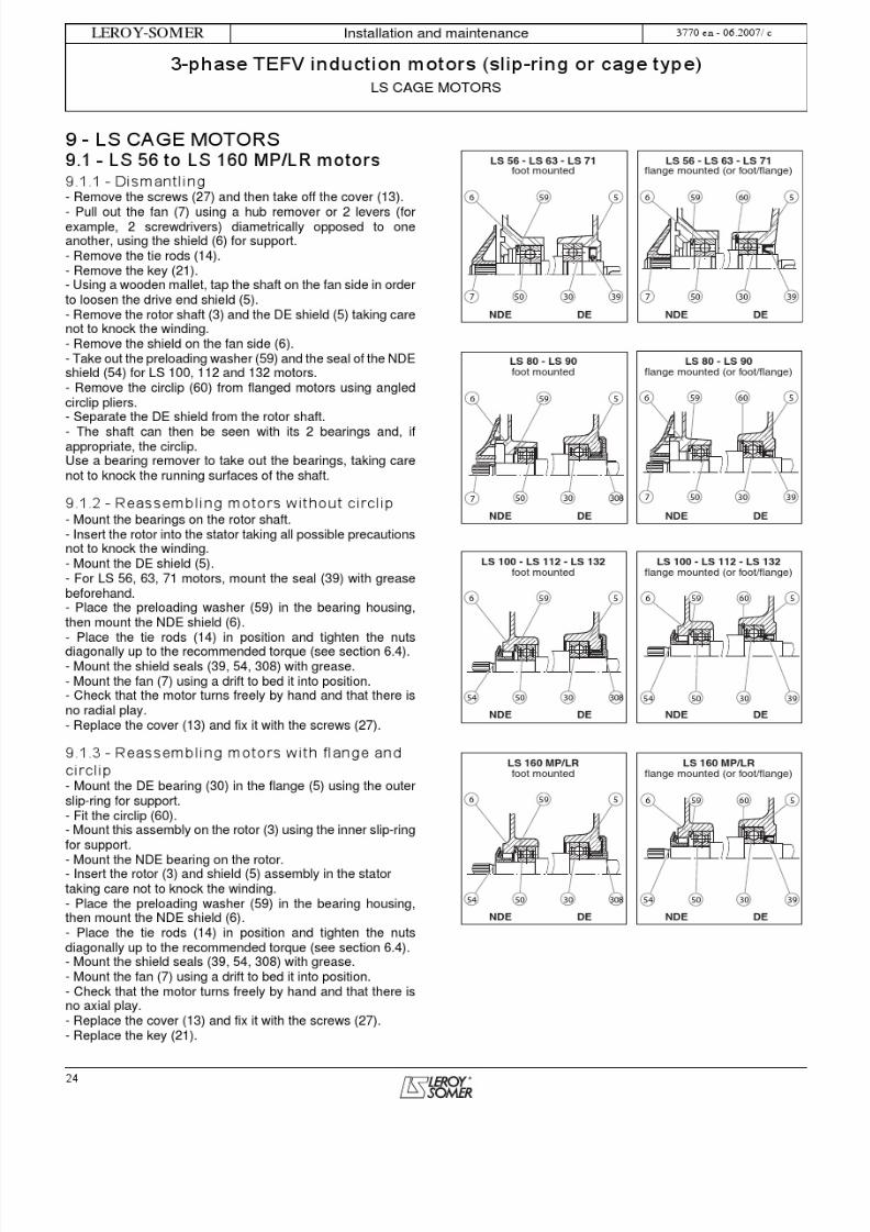
9.2 - LS 160 M/L, LS 180 MT/LR motors9.2.1 - Dismantling- Remove the screws (27) and then take off the cover (13).- Pull out the fan (7) using a hub remover or 2 leversdiametrically opposed to one another, using the shield (6) forsupport.- Take out the key (21) and remove the seals (39 and 54 forfoot mounted motors) (54 for flange mounted motors).- Unscrew the tie rods (14) then remove them.- Unscrew the inner bearing retainer (33) fixing screws (40)when using a flange mounted motor or if the drive end bearingis locked.- Using a bronze drift, remove the shields (5 and 6) by tappinggently on the shield bosses. Recover the preloading washer(59).- Remove the circlip (38) if necessary (flange mountedmotor).
- Remove the rotor (3) from the stator (1) taking care not totouch the winding.- Take out the bearings (30) and (50) using a bearingremover, while protecting the end of the shaft extension witha washer. Avoid knocking the running surfaces of the shaft.
9.2.2 - Reassembly- See section 6.1 before reassembly.- If necessary, insert the inner bearing retainer (33) at therotor drive end, then mount new bearings on the shaft, seesection 6.3 mounting bearings.- Mount the circlip (38) for flange mounted motors.- Insert the rotor (3) in the stator (1) taking care not to knock
the winding.- Position the preloading washer (59) with a small amount ofgrease in the back of the bearing cage of the NDE shield (6),then remount the NDE shield (6), positioning it on the stator.- If there is a bearing retainer (33), screw a rod with the samethread diameter as the screws (40) into one of the tappedholes of the bearing retainer to maintain its angular positionwhen remounting the DE shield (5).When there is a flange, mount a new seal (39) with the springfacing outwards.- Remount the shield (5) taking care to allow for thepositioning of a bearing retainer if used.- Place the tie rods (14) in position and tighten the nutsdiagonally up to the recommended torque (see
section 6.1).- If necessary, fix the bearing retainer (33) with its ownscrews.- Mount the shield seals with grease: (54 at the non drive end)(39 at the drive end for foot mounted motors).- Mount the fan (7) using a drift to bed it into position.- Check that the rotor turns freely by hand (that there is noaxial play if there is a locked end shield).- Replace the cover (13) and fix it with the screws (27).- Replace the key (21).
54
5
50
6 59
3930 54 3950 30 38
6 59 33 5 40
3954 50 3830
6 59 533 40
4062 6 53 33 5
3960 50 30 3854 3960 50 30 38
6 53 33 5
54
62 40
LS 160 M/L - LS 180 MT/LRfoot mounted (except V6)
standard bearings
LS 160 M/L - LS 180 MT/LRflange mounted (or foot/flange)
standard bearings
NDE DE
LS 160 M/L - LS 180 MT/LRIM V6 foot mountedstandard bearings
NDE DE
NDE DE
LS 160 M/L - LS 180 MT/LRfoot mounted
drive end roller bearings
LS 160 M/L - LS 180 MT/LRflange mounted (or foot/flange)
drive end roller bearings
NDE DE NDE DE

5/14/2018 Tefv Motor - slidepdf.com
http://slidepdf.com/reader/full/tefv-motor 27/56
27
INSTALLATION AND MAINTENANCE
3-phase TEFV induction motors (slip-ring or cage type)LS CAGE MOTORS
LEROY-SOMER 3770 en - 06.2007/ c
LS 160 M/L, LS 180 MT/LR
LS 160 M/L, LS 180 MT/LRRef. Description Ref. Description Ref. Description
1 Wound stator 14 Tie rods 39 Drive end seal
2 Frame 21 Key 40 Cover fixing screw
3 Rotor 26 Nameplate 50 Non drive end bearing
5 DE shield 27 Fan cover screw 54 Non drive end seal
6 NDE shield 30 Drive end bearing 59 Preloading (wavy) washer
7Fan
33Inner DE bearing retainer
70Terminal box
13 Fan cover 38 Drive end bearing circlip 74 Terminal box lid
1327
7
54
14
659
5074
70
3
21
39
5
301
38
33
26
2
40

5/14/2018 Tefv Motor - slidepdf.com
http://slidepdf.com/reader/full/tefv-motor 28/56

5/14/2018 Tefv Motor - slidepdf.com
http://slidepdf.com/reader/full/tefv-motor 29/56
29
INSTALLATION AND MAINTENANCE
3-phase TEFV induction motors (slip-ring or cage type)LS CAGE MOTORS
LEROY-SOMER 3770 en - 06.2007/ c
LS 180 L, LS 200, LS 225 ST/MT/MR
LS 180 L, LS 200, LS 225 ST/MT/MRRef. Description Ref. Description Ref. Description
1 Wound stator 25 Lifting ring 50 Non drive end bearing
2 Frame 26 Nameplate 54 Non drive end seal
3 Rotor 27 Fan cover screw 59 Preloading (wavy) washer
5 DE shield 30 Drive end bearing 70 Terminal box
6 NDE shield 33 Inner DE bearing retainer 74 Terminal box lid
7Fan
38Drive end bearing circlip
319Right foot
13 Fan cover 39 Drive end seal 320 Left foot
14 Tie rods 40 Cover fixing screw
21 Key 42 Grease nipples (optional for LS 180 L, LS
5
39 538
30
33
320
319
26
2
21
3
170
7425
13
5059
654
14
7
42
27
40

5/14/2018 Tefv Motor - slidepdf.com
http://slidepdf.com/reader/full/tefv-motor 30/56
30
Installation and maintenance
3-phase TEFV induction motors (slip-ring or cage type)LS CAGE MOTORS
LEROY-SOMER 3770 en - 06.2007/ c
9.4 - LS 225 MK, LS 250, LS 280 SP/MPmotors9.4.1 - Dismantling
- Remove the screws (27), the grease nipple (42) and itsextension, then take off the cover (13).- Pull out the fan (7) using a hub remover or 2 leversdiametrically opposed to one another, using the shield (6) forsupport.- Take out the key (21).- Unscrew the tie rods (14) then remove them.- Unscrew the DE bearing retainer (33) fixing screws (40) andNDE bearing retainer (52) and (53) fixing screws (62), andremove them.- Using a bronze drift, remove the shields (5 and 6) by tappinggently on the shield bosses. Recover the preloading washer(59).- Remove circlips (38) and (60).- Remove the rotor (3) from the stator (1), taking care not totouch the winding with the inner bearing retainer.- Take out the bearings (30) and (50) using a bearingremover, while protecting the end of the shaft extension witha washer. Avoid knocking the running surfaces of the shaft.- The bearings are removed either separately or with thebearing retainers; to avoid damaging the bearing retainers,heat the outer bearing retainer to make it easier to dismantle(the bearing should be discarded).
9.4.2 - Reassembly- See section 6.1 before reassembly.- Insert the inner bearing retainer (33) at the rotor drive end
and the inner bearing retainer (53) at the non drive end.- Add new grease: the correct amount of new grease for thebearing is 50% of the free space.- Mount the new bearings on the shaft, see section 6.3 onmounting bearings.- Mount the circlips (38) and (60).- Insert the rotor (3) in the stator (1) taking care not to knockthe winding.- Screw a rod with the same thread diameter as the screws(40 and 62) into one of the tapped holes of the bearingretainers (33 and 53) to maintain their position and that of thegrease nipple when remounting the shields (5 and 6).- Position the preloading washer (59) with a small amount of
grease in the back of the bearing cage of the NDE shield (6),then remount the NDE shield (6), positioning it on the stator.- Fit the seal (54), the outer bearing retainer (52) and thelocking screws (62) for the bearing retainers (52, 53).- Mount the shield (5) taking care to allow for the positioningof the bearing retainer.- Put the tie rods (14) in place, not forgetting the feet of theprotective cover (380), tighten the nuts diagonally withoutlocking them so that the feet of the protective cover can bepositioned when it is mounted.- At the drive end fit the seal (39) and its support (386), insertthe bearing retainer (32) and the locking screws (40) for thebearing retainer.- Mount the fan (7) using a drift to bed it in position or by
heating the hub of the aluminium fan to approximately 100°C.- Check that the motor turns freely by hand and that there isno axial play.
- Replace the cover (13), fixing it with the screws (27).- Replace the grease nipple (42) and extension.- Tighten the rod nuts (14) diagonally up to the torquerecommended in section 6.1.
- Replace the key (21).
6 40
3952
59 53 33 5 386
54 50 30 38
62 32
3253 33 386 5
3954 60 50 30 38
40
6
52
62
LS 225 MK - LS 250
LS 280 SP/MP
standard bearings
NDE DE
LS 225 MK - LS 250
LS 280 SP/MP
drive end roller bearings
NDE DE
5/14/2018 Tefv Motor - slidepdf.com
http://slidepdf.com/reader/full/tefv-motor 31/56
31
INSTALLATION AND MAINTENANCE
3-phase TEFV induction motors (slip-ring or cage type)LS CAGE MOTORS
LEROY-SOMER 3770 en - 06.2007/ c
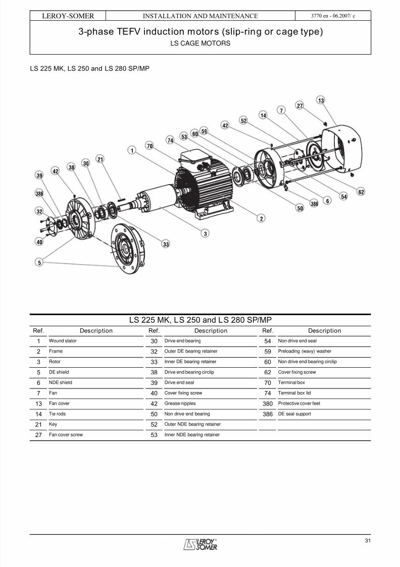
LS 225 MK, LS 250 and LS 280 SP/MP
LS 225 MK, LS 250 and LS 280 SP/MPRef. Description Ref. Description Ref. Description
1 Wound stator 30 Drive end bearing 54 Non drive end seal
2 Frame 32 Outer DE bearing retainer 59 Preloading (wavy) washer
3 Rotor 33 Inner DE bearing retainer 60 Non drive end bearing circlip
5 DE shield 38 Drive end bearing circlip 62 Cover fixing screw
6 NDE shield 39 Drive end seal 70 Terminal box
7Fan
40Cover fixing screw
74Terminal box lid
13 Fan cover 42 Grease nipples 380 Protective cover feet
14 Tie rods 50 Non drive end bearing 386 DE seal support
21 Key 52 Outer NDE bearing retainer
27 Fan cover screw 53 Inner NDE bearing retainer
5
3
2
50
6 54
62
33
32
38
39
386
3021
170
7453
6059
14
27
52
42
7
40
42
13
386

5/14/2018 Tefv Motor - slidepdf.com
http://slidepdf.com/reader/full/tefv-motor 32/56
32
Installation and maintenance
3-phase TEFV induction motors (slip-ring or cage type)LS CAGE MOTORS
LEROY-SOMER 3770 en - 06.2007/ c
9.5 - LS 280 SK/MK, LS 315 motors9.5.1 - Dismantling- Remove the screws (27), the grease nipple (42) and itsextension, then take off the cover (13).- Pull out the fan (7) using a hub remover or 2 diametricallyopposed levers, using the shield (6) for support; for analuminium fan, heat the hub to approximately 100°C beforeremoving it.- Take out the key (21).- Unscrew the tie rods (14) then remove them.- Unscrew the DE bearing retainer (33) fixing screws (40) andNDE bearing retainer (32) and (52) fixing screws (62), andremove the bearing retainers.- Unscrew the "CHc" screws of the mobile valves (35 and 56)then unscrew the valves using a hook spanner or a conicalbronze drift; unscrew the valves by hand and remove them.The valves hold the seal (39 and 54).
- Remove the fixed valves (34 and 35) from the bearinghousings.- Using a bronze drift, remove the shields (5 and 6) by tappinggently on the shield bosses.- Check that the bearing retainer (53) is smaller in diameterthan the stator, otherwise remove the bearing (50) as per thefollowing instructions.- Remove the rotor (3) from the stator (1) at the drive end,taking care not to touch the winding with the inner bearingretainer if there is no internal turbine.- Take out the bearings (30) and (50) using a bearingremover, while protecting the end of the shaft extension witha washer. Avoid knocking the running surfaces of the shaft.
- The bearings are removed either separately or with thebearing retainers (33 and 53); to avoid damaging the bearingretainers, heat the outer bearing ring (the bearing should bediscarded).- Recover the preloading washer or springs (59) from thebearing retainer (53).9.5.2 - Reassembly- See section 6.1 before reassembly.- Insert the inner bearing retainer (33) at the rotor drive endand the inner bearing retainer (53) at the non drive end, notforgetting to insert the preloading springs (59).- Add new grease: the correct amount of new grease for thebearing is 50% of the free space.- Mount the new bearings (30 and 50) on the shaft, see
section 6.3 on mounting bearings.- Insert the rotor (3) in the stator (1) taking care not to knockthe winding.- Screw a rod with the same thread diameter as the screws(40) and (62) into one of the tapped holes of the bearingretainers (33) and (53) to maintain the position of the greasenipple when remounting the shields (5 and 6).- Check that the preloading springs are properly installed.- Fit the NDE shield (6), positioning it on the stator, thenmount the fixed valve (55) in the shield bearing housing.- Mount the mobile valve (56) by either screwing it or lockingit, having carefully installed the seal (54) on the valve.
- Mount the outer bearing retainer (52) with the bearingretainer locking screws (62), making sure that the greasedrain hole is at the bottom.- Mount the shield (5) at the drive end, positioning it on the
stator, then mount the fixed valve (34) in the shield bearinghousing.- Mount the mobile valve (35) by either screwing it or lockingit, having carefully installed the seal (39) on the valve.- Mount the outer bearing retainer (32) with the bearingretainer locking screws (40), making sure that the greasedrain hole is at the bottom.- Put the tie rods (14) in place, not forgetting the feet of theprotective cover (380), tighten the nuts diagonally withoutlocking them so that the feet of the protective cover can bepositioned when it is mounted.- Mount the fan (7) using a drift to bed it in position or byheating the hub of the aluminium fan to approximately 100°C.- Check that the motor turns freely by hand and that there isno axial play.- Replace the protective cover (13) and fix it with the screws(27), replace the grease nipple (42) and its extension.- Tighten the rod nuts (14), always diagonally, up to the torquerecommended in section 6.1.- Replace the key (21).
52 32
3956
6 59 53 33 5
54 50 30 34 35
62 40
55
3255 6 53 33 5
3954 50 30 35
40
52
62
3456
LS 280 SK/MK - LS 315
standard bearings
LS 280 SK/MK - LS 315
drive end roller bearings
NDE DE
NDE DE

5/14/2018 Tefv Motor - slidepdf.com
http://slidepdf.com/reader/full/tefv-motor 33/56
33
INSTALLATION AND MAINTENANCE
3-phase TEFV induction motors (slip-ring or cage type)LS CAGE MOTORS
LEROY-SOMER 3770 en - 06.2007/ c
LS 280 SK/MK and LS 315
LS 280 SK/MK and LS 315Ref. Description Ref. Description Ref. Description
1 Wound stator 30 Drive end bearing 53 Inner NDE bearing retainer
2 Frame 32 Outer DE bearing retainer 54 Non drive end seal
3 Rotor 33 Inner DE bearing retainer 55 NDE fixed grease valve
5 DE shield 34 DE fixed grease valve 56 NDE mobile grease valve
6 NDE shield 35 DE mobile grease valve 59 Preloading washer or spring
7 Fan 39 Drive end seal 62 Cover fixing screw
13 Fan cover 40 Cover fixing screw 70 Terminal box
14 Tie rods 42 Grease nipples 74 Terminal box lid
21 Key 50 Non drive end bearing 380 Protective cover feet
27 Fan cover screw 52 Outer NDE bearing retainer
5
39
32
35
34
3021
33
3
2
59
55
62
170
7453
4254
5214
7
1327
42
40
6
38050
56

5/14/2018 Tefv Motor - slidepdf.com
http://slidepdf.com/reader/full/tefv-motor 34/56
34
Installation and maintenance
3-phase TEFV induction motors (slip-ring or cage type)FLS-FLSC CAGE MOTORS
LEROY-SOMER 3770 en - 06.2007/ c
10 - FLS-FLSC CAGE MOTORS10.1 - FLS-FLSC 80 to 132 motors10.1.1 - Dismantling
- Remove the screws (27) and then take off the cover (13).- Pull out the fan (7) using a hub remover or 2 levers (forexample, 2 screwdrivers) diametrically opposed to oneanother, using the shield (6) for support.- Remove the tie rods (14).- Remove the key (21).- Using a wooden mallet, tap the shaft on the fan side in orderto loosen the drive end shield (5).- Remove the rotor shaft (3) and the DE shield (5) taking carenot to knock the winding.- Remove the shield on the fan side (6).- Recover the preloading (wavy) washer (59) and the NDEshield seal (54).- Remove the circlip (60) from flanged motors using angledcirclip pliers.- Separate the DE shield from the rotor shaft.- The shaft can then be seen with its 2 bearings and, ifappropriate, the circlip.Use a bearing remover to take out the bearings, taking carenot to knock the running surfaces of the shaft.
10.1.2 - Reassembling motors without circlip- Mount the bearings on the rotor shaft.- Insert the rotor into the stator taking all possible precautionsnot to knock the winding.- Mount the DE shield (5).- Place the preloading washer (59) in the bearing housing,
then mount the NDE shield (6).- Place the tie rods (14) in position and tighten the nutsdiagonally up to the recommended torque (see section 6.4).- Mount the shield seals (39, 54, 308) with grease.- Mount the fan (7) using a drift to bed it into position.- Check that the motor turns freely by hand and that there isno radial play.- Replace the cover (13) and fix it with the screws (27).
10.1.3 - Reassembling motors with flange andcirclip- Mount the DE bearing (30) in the flange (5) using theexternal slip-ring for support.
- Fit the circlip (60).- Mount this assembly on the rotor (3) using the inner slip-ringfor support.- Mount the NDE bearing on the rotor.- Insert the rotor (3) and shield (5) assembly in the statortaking care not to knock the winding.- Place the preloading washer (59) in the bearing housing,then mount the NDE shield (6).- Place the tie rods (14) in position and tighten the nutsdiagonally up to the recommended torque (see section 6.4).- Mount the shield seals (39, 54, 308) with grease.- Mount the fan (7) using a drift to bed it into position.- Check that the motor turns freely by hand and that there isno axial play.
- Replace the cover (13) and fix it with the screws (27).- Replace the key (21).
56 59
54 50 30830
56 59
50 3054 39
60
FLS - FLSC 80 to 132foot mounted
FLS - FLSC 80 to 132flange mounted (or foot/flange)
NDE DE NDE DE

5/14/2018 Tefv Motor - slidepdf.com
http://slidepdf.com/reader/full/tefv-motor 35/56
35
INSTALLATION AND MAINTENANCE
3-phase TEFV induction motors (slip-ring or cage type)FLS-FLSC CAGE MOTORS
LEROY-SOMER 3770 en - 06.2007/ c
FLS-FLSC 80 to 132
FLS-FLSC 80 to 132Ref. Description Ref. Description Ref. Description
1 Wound stator 21 Shaft extension key 54 Non drive end seal
2 Housing 22 Shaft extension washer 59 Preloading (wavy) washer
3 Rotor 23 Shaft end screw 60 Circlip
5 DE shield 26 Nameplate 71a FLS terminal box
6 NDE shield 27 Fan cover screw 71b FLSC terminal box
7 Fan 30 Drive end bearing 78 Cable gland
13 Fan cover 39 Drive end seal 84 Terminal block with terminals
14 Tie rods 50 Non drive end bearing 308 Labyrinth seal
71 b
78
21
3
5
22
5
5
308
23 IM B3
IM B14
IM B5
13
27
14
7
54
6
84
26
2
1
60
59
50
30
71 a
39
26
78
39
84

5/14/2018 Tefv Motor - slidepdf.com
http://slidepdf.com/reader/full/tefv-motor 36/56
36
Installation and maintenance
3-phase TEFV induction motors (slip-ring or cage type)FLS-FLSC CAGE MOTORS
LEROY-SOMER 3770 en - 06.2007/ c
10.2 - FLS-FLSC 160 and 180 motors10.2.1 - Dismantling the NDE shield- Remove the fixing screws (27) and then take off the cover(13).- Take out the fan (7).- Remove the fixing screws (273) from the NDE shield (6).- Using two levers or a flexible hammer, disengage the NDEshield (6) taking care not to place it aslant. Remove theshield by sliding it along the shaft. The seal (54) followsbehind and is no longer usable.- Recover the preloading washer (59) which should bereplaced in its housing.
10.2.2 - Dismantling the DE shield- Remove the fixing screws (270) from the DE shield.- Using an appropriate lifting tool, take out the rotor (3) + DEshield (5) assembly, without knocking the winding.
- Remove the fixing screws (40) from the inner DE bearingretainer (33).- Take out the key (21).- Using two levers or a flexible hammer, disengage the DEshield (5) from the rotor (3) taking care not to place it aslant.- Remove the shield by sliding it along the shaft. The seal (39)follows behind and is no longer usable.
10.2.3 - Changing the antifriction bearings- Remove the bearings (30) and (50) with an appropriate tool,protecting the end of the shaft extension. Avoid knocking therunning surfaces of the shaft.- Change the bearings in accordance with the instructions
described in the General information in section 6(shrink-fitting only).
IMPORTANT: Before undertaking any of these procedures,read the "CHECKS BEFORE REASSEMBLY" section.
10.2.4 - Reassembly- Mount the bearings on the rotor shaft (not forgetting theinner DE bearing retainer (33)!).- Slide the DE shield (5) onto the bearing (30).- Replace the fixing screws (40) on the inner bearing retainer(33).- Insert the rotor + shield assembly in the stator without
knocking the winding.- Present the shields, grease nipples facing upwards, notforgetting the preloading washer (59) at the non-drive end.Slide them into position.- Fit the shields firmly in place.- Check that the rotor turns freely by hand.
From now on, we recommend checking at every step thatthe rotor turns freely by hand before continuing to thenext instruction.- Replace the shield fixing screws (270) and (273).- Use a drift to fit a new seal (54).- Replace the fan (7).- Replace the cover (13) and reinsert the fixing screws (27).
- Use a drift to fit the new seal (39).- Lubricate the DE and NDE antifriction bearings, turning theshaft by hand.
Amount of grease for ball bearings:- Frame size 160: DE = 40 cm3 /NDE = 20 cm3
- Frame size 180: DE = 50 cm3 /NDE = 35 cm3
(except for 180 MR NDE = 20 cm3)
56 59
50 3054 39
33 56 59
50 3054 39
33
56 53
50 39 393054
33 56 53
50 3054
33
56 59
50 3054 39
33
FLS - FLSC 160 and 180foot mounted (except V6)
standard bearings
FLS - FLSC 160 and 180flange mounted (or foot/flange)
standard bearings
NDE DE
FLS - FLSC 160 and 180IM V6 foot mountedstandard bearings
NDE DE
FLS - FLSC 160 and 180flange mounted (or foot/flange)
drive end roller bearings
NDE DE
FLS - FLSC 160 and 180foot mounted
drive end roller bearings
NDE DE
NDE DE

5/14/2018 Tefv Motor - slidepdf.com
http://slidepdf.com/reader/full/tefv-motor 37/56
37
INSTALLATION AND MAINTENANCE
3-phase TEFV induction motors (slip-ring or cage type)FLS-FLSC CAGE MOTORS
LEROY-SOMER 3770 en - 06.2007/ c
FLS-FLSC 160 and 180
FLS-FLSC 160 and 180Ref. Description Ref. Description Ref. Description
1 Wound stator 27 Fan cover screw 59 NDE preloading (wavy) washer
2 Housing 30 Drive end bearing 64 NDE grease nipple
3 Rotor 33 Inner DE bearing retainer 70 Stator terminal box5 DE shield 39 DE seal 74 Terminal box lid
6 NDE shield 40 Cover fixing screw 81 Cable gland support plate
7 Fan 42 DE grease nipple 270 DE shield fixing screw
13 Fan cover 50 Non drive end bearing 273 NDE shield fixing screw
21 Shaft extension key 54 NDE seal

5/14/2018 Tefv Motor - slidepdf.com
http://slidepdf.com/reader/full/tefv-motor 38/56
38
Installation and maintenance
3-phase TEFV induction motors (slip-ring or cage type)FLS-FLSC CAGE MOTORS
LEROY-SOMER 3770 en - 06.2007/ c
10.3 - FLS-FLSC 200 to 225 ST motors10.3.1 - Dismantling the NDE shield- Remove the fixing screws (27) and then take off the cover(13).- Take out the fan (7).- Remove the fixing screws from the inner NDE bearingretainer (53).- Remove the fixing screws (273) from the NDE shield (6).- Using two levers or a flexible hammer, disengage the NDEshield (6) taking care not to place it aslant. Remove theshield by sliding it along the shaft. The seal (54) followsbehind and is no longer usable.- Put the dismantled components to one side and recover thepreloading washer (59), which should be replaced in itshousing.
10.3.2 - Dismantling the DE shield- Dismantle the DE shield without removing the rotor (3). To dothis:- Remove the fixing screws (40) from the inner DE bearingretainer (33).- Remove the fixing screws (270) from the DE shield (5).- Remove the fixing screws from the inner DE bearing retainer(33).- Take out the key (21).- Using two levers or a flexible hammer, disengage the DEshield (5) taking care not to place it aslant.- Remove the shield by sliding it along the shaft. The seal (39)follows behind and is no longer usable.
10.3.3 - Changing the antifriction bearings- Using an appropriate lifting tool, take out the rotor withoutknocking the winding.- Remove the bearings (30) and (50) with an appropriate tool,protecting the end of the shaft extension. Avoid knocking therunning surfaces of the shaft.- The moving parts of the grease valve (35) for the drive endand (56) for the non-drive end follow.- Put the components to one side (55) - (56) for the non-driveend and (34) - (35) for the drive end.- Change the bearings in accordance with the instructionsdescribed in the General information in section 6(shrink-fitting only).
IMPORTANT: Before undertaking any of these procedures,read the "CHECKS BEFORE REASSEMBLY" section.
10.3.4 - Reassembly- Mount the DE bearing (30) on the rotor shaft (take care notto forget the inner bearing retainer (33)!), and also the NDEbearing (50) if and only if the stator inner Ø allows the innerNDE bearing retainer (53) to pass through.- Install the fixed part of the grease valves (no. (55) for thenon-drive end and (34) for the drive end).- Shrink-fit the moving part of the grease valves (no. (56) forthe non-drive end and (35) for the drive end). Make absolutelysure that it is resting on the inner slip-ring.
- Insert the rotor into the stator taking care not to knock thewinding. Install the NDE bearing if this has not already beendone.
- Present the shields, grease nipples facing upwards. Beginwith the DE shield (5). Fix a dowel pin in one of the innerbearing retainer (33) tapped holes so that the grease inletpipes fully correspond. Slide it into position.
- End with the NDE shield (6). Fix a dowel pin in one of theinner bearing retainer (53) tapped holes so that the greaseinlet pipes fully correspond.- Lift the rotor slightly and fit the shields onto the housing.
From now on, we recommend checking at every step thatthe rotor turns freely by hand before continuing to thenext instruction.- Replace the shield fixing screws (270) and (273).- Replace the fixing screws on the inner bearing retainers (33)and (53).- Use a drift to fit a new seal (54).- Replace the fan (7).- Use a drift to fit a new seal (39).- Replace the cover (13) and reinsert the fixing screws (27).- Lubricate the DE and NDE antifriction bearings, turning theshaft by hand.
Amount of grease for ball bearings:- DE and NDE = 100 cm3
3935343054 50
533536
39343054 50
533536
FLS - FLSC 200 to 225 STstandard bearings
NDE DE
FLS - FLSC 200 to 225 STdrive end roller bearings
NDE DE

5/14/2018 Tefv Motor - slidepdf.com
http://slidepdf.com/reader/full/tefv-motor 39/56
39
INSTALLATION AND MAINTENANCE
3-phase TEFV induction motors (slip-ring or cage type)FLS-FLSC CAGE MOTORS
LEROY-SOMER 3770 en - 06.2007/ c
FLS-FLSC 200 to 225 ST
FLS-FLSC 200 to 225 STRef. Description Ref. Description Ref. Description
1 Wound stator 33 Inner DE bearing retainer 56 Moving part of NDE grease valve
2 Housing 34 Fixed part of DE grease valve 59 NDE preloading (wavy) washer
3 Rotor 35 Moving part of DE grease valve 64 NDE grease nipple
5 DE shield 39 DE seal 70 Stator terminal box
6 NDE shield 40 Cover fixing screw 74 Stator terminal box lid
7 Fan 42 DE grease nipple 81 Cable gland support plate
13 Fan cover 50 Non drive end bearing 270 DE shield fixing screw
21 Shaft extension key 53 Inner NDE bearing retainer 273 NDE shield fixing screw
27 Fan cover screw 54 NDE seal 406 DE grease valve cover plate
30 Drive end bearing 55 Fixed part of NDE grease valve 456 NDE grease valve cover plate

5/14/2018 Tefv Motor - slidepdf.com
http://slidepdf.com/reader/full/tefv-motor 40/56
40
Installation and maintenance
3-phase TEFV induction motors (slip-ring or cage type)FLS-FLSC CAGE MOTORS
LEROY-SOMER 3770 en - 06.2007/ c
10.4 - FLS-FLSC 225 M to 280 motors10.4.1 - Dismantling the NDE shield- Remove the fixing screws (27) and then take off the cover(13).- Remove the shaft extension screw if necessary.- Take out the fan (7).- Remove the fixing screws from the inner NDE bearingretainer (53).- Remove the fixing screws (273) from the NDE shield (6).- Remove the fan key if appropriate.- Using two levers or a flexible hammer, disengage the NDEshield (6) taking care not to place it aslant. Remove the shieldby sliding it along the shaft.- Put the dismantled components to one side and recover thepreloading washer (59), which should be replaced in itshousing.
10.4.2 - Dismantling the DE shield- Dismantle the DE shield without removing the rotor (3). To dothis:- Remove the fixing screws (270) from the DE shield (5).- Remove the fixing screws (40) from the DE internal cover(33).- Take out the key (21).- Using two levers or a flexible hammer, disengage the DEshield (5) taking care not to place it aslant.- Remove the shield by sliding it along the shaft.
10.4.3 - Changing the antifriction bearings- Using an appropriate lifting tool, take out the rotor without
knocking the winding.- Take off the DE circlip (38).- Remove the bearings (30) and (50) with an appropriate tool,protecting the end of the shaft extension. Avoid knocking therunning surfaces of the shaft.- Change the bearings in accordance with the instructionsdescribed in the General information in section 6 (shrink-fitting only).
IMPORTANT: Before undertaking any of these procedures,read the "CHECKS BEFORE REASSEMBLY" section.
10.4.4 - Reassembly
- Mount the DE bearing (30) on the rotor shaft (take care notto forget the inner bearing retainer (33) and the circlip (38)!),and also the NDE bearing (50) if and only if the stator inner Øallows the inner NDE bearing retainer (53) to pass through.- Insert the rotor into the stator taking care not to knock thewinding. Install the NDE bearing if this has not already beendone.- Fill the decompression grooves (416) located in theshaftway with grease.- Present the shields, grease nipples facing upwards. Beginwith the DE shield (5). Fix a dowel pin in one of the innerbearing retainer (33) tapped holes so that the grease inletpipes fully correspond.- End with the NDE shield (6). Fix a dowel pin in one of the
inner bearing retainer (53) tapped holes so that the greaseinlet pipes fully correspond.- Lift the rotor slightly and fit the shields in place.
From now on, we recommend checking at every step thatthe rotor turns freely by hand before continuing to thenext instruction.
- Replace the shield fixing screws (270) and (273).- Insert the fixing screws on the inner bearing retainers (33)and (53). Replace the AZ washers to ensure a perfect seal.- Replace the fan key if appropriate.- Replace the fan (7).- Replace the shaft extension screw if necessary.- Replace the cover (13) and reinsert the fixing screws (27).- Lubricate the DE and NDE antifriction bearings, turning theshaft by hand.
Amount of grease for ball bearings:- Frame size 225 - 250: DE and NDE = 120 cm3
- Frame size 280: DE = 170 cm3/NDE = 120 cm3
505333
5 6416
505333
5 6416
FLS - FLSC 225 M to 280standard bearings
NDE DE
FLS - FLSC 225 M to 280drive end roller bearings
NDE DE
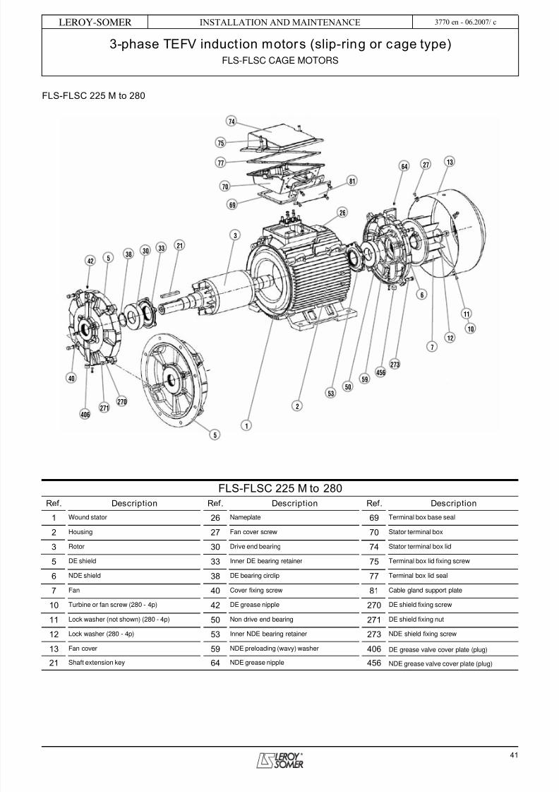
5/14/2018 Tefv Motor - slidepdf.com
http://slidepdf.com/reader/full/tefv-motor 41/56
41
INSTALLATION AND MAINTENANCE
3-phase TEFV induction motors (slip-ring or cage type)FLS-FLSC CAGE MOTORS
LEROY-SOMER 3770 en - 06.2007/ c
FLS-FLSC 225 M to 280
FLS-FLSC 225 M to 280Ref. Description Ref. Description Ref. Description
1 Wound stator 26 Nameplate 69 Terminal box base seal
2 Housing 27 Fan cover screw 70 Stator terminal box
3 Rotor 30 Drive end bearing 74 Stator terminal box lid
5 DE shield 33 Inner DE bearing retainer 75 Terminal box lid fixing screw
6 NDE shield 38 DE bearing circlip 77 Terminal box lid seal
7 Fan 40 Cover fixing screw 81 Cable gland support plate
10 Turbine or fan screw (280 - 4p) 42 DE grease nipple 270 DE shield fixing screw
11 Lock washer (not shown) (280 - 4p) 50 Non drive end bearing 271 DE shield fixing nut
12 Lock washer (280 - 4p) 53 Inner NDE bearing retainer 273 NDE shield fixing screw
13 Fan cover 59 NDE preloading (wavy) washer 406 DE grease valve cover plate (plug)
21 Shaft extension key 64 NDE grease nipple 456 NDE grease valve cover plate (plug)
40
542
3830
33 21
3
26
81
74
75
77
70
69
64 27
406
270271
1
2
5350
456
59
273
6
7
12
13
5
10
11

5/14/2018 Tefv Motor - slidepdf.com
http://slidepdf.com/reader/full/tefv-motor 42/56
42
Installation and maintenance
3-phase TEFV induction motors (slip-ring or cage type)FLS-FLSC CAGE MOTORS
LEROY-SOMER 3770 en - 06.2007/ c
10.5 - FLS-FLSC 315 to 355 LD motorsNote:- There is a stirrer at the drive end of the 315 M up to the 355.- Types 315 M and L, and all 355s have fixed NDE bearings:
the preloading washer (59) is therefore at the drive end.- Type 315 S has a fixed DE bearing, and the preloadingwasher (59) is therefore at the non-drive end.This should be taken into account during dismantling/ reassembly operations.
10.5.1 - Dismantling the NDE shield- Remove the grease nipple extension (65).- Remove the fixing screws (27) and then take off the cover(13).- Remove the screws and washer from the shaft extension.- Take out the fan (7).- Take out the fan key (not shown) and the moving part of the
grease valve (56).- Remove the fixing screws from the inner NDE bearingretainer (53).- Remove the fixing screws (273) from the NDE shield (6).- Using two levers or a flexible hammer, disengage the NDEshield (6). Remove the shield by sliding it along the shaft.- Put the dismantled components to one side and recover thepreloading washers (59), which should be replaced in theirhousing (for the 315 S).
10.5.2 - Dismantling the DE shield- Dismantle the DE shield without removing the rotor (3). To dothis:
- Take out the key (21).- Heat the moving part of the DE grease valve (35). Unscrewand remove it.- Remove the fixing screws from the inner DE bearing retainer(33).- Remove the fixing screws (270) from the DE shield.- Using two levers or a flexible hammer, disengage the DEshield (5) taking care not to place it aslant.- Remove the shield by sliding it along the shaft.- Place the dismantled components to one side and recoverpart no. (35) which should be replaced in its housing, alongwith the preloading washers (59) (for the 315 M to 355 LD).
10.5.3 - Changing the antifriction bearings- Using an appropriate lifting tool, take out the rotor withoutknocking the winding.- Remove the bearings (30) and (50) with an appropriate tool,protecting the end of the shaft extension. Avoid knocking therunning surfaces of the shaft.- Change the bearings in accordance with the instructionsdescribed in the General information in section 6 (shrink-fitting only).
IMPORTANT: Before undertaking any of these procedures,read the "CHECKS BEFORE REASSEMBLY" section.
10.5.4 - Reassembly- Mount the DE bearing (30) on the rotor shaft (take care notto forget the inner bearing retainer (33)!), and also the NDEbearing (50) and the inner NDE bearing retainer (53).- Insert the rotor in the stator taking care not to knock thewinding.
- Don't forget to replace the preloading washers (59) in theirhousing.- Begin with the fixed bearing (see above). Fix a dowel pin inone of the inner bearing retainer tapped holes so that the
grease inlet pipes fully correspond.- End with the non-fixed bearing. Fix a dowel pin in one of theinner bearing retainer tapped holes so that the grease inletpipes fully correspond.- Lift the rotor slightly and fit the shields in place.
From now on, we recommend checking at every step thatthe rotor turns freely by hand before continuing to thenext instruction.- Replace the shield fixing screws (270) and (273).- Replace the inner bearing retainer fixing screws (33) and(53).- Refit the moving part of the grease valve (56).- Replace the fan (7) with its key.- Replace the shaft extension screw with its washer.- Replace the cover (13).- Coat the thread of the moving part of the DE grease valve(35), with anti-vibration adhesive. Screw it tight.- Lubricate the DE and NDE bearings.
Amount of grease for ball bearings:- frame size 315S: DE and NDE = 235 cm3 /frame size
315 M/L: DE and NDE = 335 cm3 /frame size 355: DE andNDE = 445 cm3
Amount of grease for DE roller bearings:- frame size 315S: 350 cm3 /frame size 315 M/L: 500 cm3 /
frame size 355: 665 cm3
59 6 53 33 5
50 3056 35
6 53 33 5 44
50 3056 35
6 53 33 5
50 3056 35
FLS - FLSC 315 STstandard bearings
FLS - FLSC 315 M, L355 LA, LB, LC, LDstandard bearings
NDE DE
FLS - FLSC 315 to 355 LDdrive end roller bearings
NDE DE
NDE DE

5/14/2018 Tefv Motor - slidepdf.com
http://slidepdf.com/reader/full/tefv-motor 43/56
43
INSTALLATION AND MAINTENANCE
3-phase TEFV induction motors (slip-ring or cage type)FLS-FLSC CAGE MOTORS
LEROY-SOMER 3770 en - 06.2007/ c
FLS-FLSC 315 to 355 LD
FLS-FLSC 315 to 355 LDRef. Description Ref. Description Ref. Description
1 Wound stator 27 Fan cover screw 65 Extension for NDE grease nipple
2 Housing 30 Drive end bearing 70 Stator terminal box
3 Rotor 33 Inner DE bearing retainer 74 Stator terminal box lid
5 DE shield 35 Moving part of DE grease valve 81 Cable gland support plate
6 NDE shield 40 Cover fixing screw 89 Connection - Terminal box
7 Fan 42 DE grease nipple 122 Stirrer (only from 315 M to 355 LD)
10 Turbine or fan screw 43 Extension for DE grease nipple 270 DE shield fixing screw
11 Lock washer (not shown) 50 Non drive end bearing 271 DE shield fixing nut
12 Lock washer 53 Inner NDE bearing retainer 273 NDE shield fixing screw
13 Fan cover 56 Moving part of NDE grease valve 406 DE grease valve cover plate
21 Shaft extension key 59 NDE preloading (wavy) washer 456 NDE grease valve cover plate
26 Nameplate 64 NDE grease nipple
727
10
11
6
56
456273
12
13
59
7074
89
5350
64
181
2
3
5
4230
435
270
35
40
271
21
406
33
65
270
122
26

5/14/2018 Tefv Motor - slidepdf.com
http://slidepdf.com/reader/full/tefv-motor 44/56
44
Installation and maintenance
3-phase TEFV induction motors (slip-ring or cage type)FLS-FLSC CAGE MOTORS
LEROY-SOMER 3770 en - 06.2007/ c
10.6 - FLS-FLSC 355 LK to 450 motors10.6.1 - Dismantling the NDE shield- Remove the grease nipple extension (65).- Remove the fixing screws (27) and then take off the cover(13). There is a tapped hole into which you can screw a liftingring to make it easier to remove.- Remove the fan screw and washer (10 -12) and the lockwasher (11).- Take out the fan (7).- Take out the fan key (not shown) and the moving part of thegrease valve (56).- Remove the fixing screws from the inner NDE bearingretainer (53).- Remove the fixing screws (273) from the NDE shield.- Using two levers, disengage the NDE shield (6). Screw alifting ring in place of one of the cover fixing screws. Turn theshield so that the ring is at the top. Remove the shield with a
lifting block by sliding it along the shaft.
10.6.2 - Dismantling the DE shield- Dismantle the DE shield without removing the rotor (3). To dothis:- Take out the key (21).- Heat the moving part of the DE grease valve (35). Unscrewand remove it.- Remove the fixing screws from the inner DE bearing retainer(33).- Remove the fixing screws (270) from the DE shield.- Using two levers or a flexible hammer, disengage the DEshield (5) taking care not to place it aslant.
- Remove the shield by sliding it along the shaft.- Put the dismantled components to one side and recover themoving part of the DE grease valve (35), which should bereplaced in its housing.
10.6.3 - Changing the antifriction bearings- The operation can be performed without removing the rotor.- Push back the inner bearing retainers (53) and (33) to makeit easier to insert the bearing extractor tool. Take out thebearings.
IMPORTANT: Before undertaking any of these procedures,read the "CHECKS BEFORE REASSEMBLY" section.
10.6.4 - Reassembly- Mount the DE bearing (30) and NDE bearing (50) on therotor shaft.- Don't forget to replace the preloading washers (59) in theirhousing.- Start with the NDE shield (6). Fix a dowel pin in one of theinner bearing retainer (53) tapped holes so that the greaseinlet pipes fully correspond.- End with the DE shield (5). Fix a dowel pin in one of the innerbearing retainer (33) tapped holes so that the grease inletpipes fully correspond.- Engage the shield on the bearing. Turn it so that the greasenipple is brought to the top.
- Slide it into position.- Lift the rotor slightly and fit the shields onto the housing.- Replace the shield fixing screws.- Replace the cover fixing screws.- Refit the moving part of the grease valve.
- Replace the fan (7) with its key.- Replace the shaft extension screw with its washers (10) (11)(12).- Replace the cover.
- Replace the grease nipple extension (65).- Coat the thread of the moving part of the DE grease valve(35), with anti-vibration adhesive. Screw it tight.- Lubricate the DE and NDE bearings.
Amount of grease for ball bearings:- frame size 355 LK - 400 L: DE and NDE = 575 cm3 / frame size 400LK - 450: DE and NDE = 855 cm3
Amount of grease for DE roller bearings:- frame size 355 LK - 400 L: 860 cm3 / frame size 400LK - 450: 1,280 cm3
Note: Removing the rotor if necessary- Place 1 sling at each end of the rotor. Lift it with a lifting blockuntil it is no longer resting on the stator. Move it as far back asyou can. Put the rotor back down and replace the slings, thenrepeat the operation as often as necessary.- When you can no longer fix the DE sling (rotor too farengaged in the stator), keep the NDE sling.- Lift a little, engage a hollow bar on the shaft and use it as alever to compensate for the weight of the rotor.- Remove the rotor.
6 53 33 5 44
50 3056 35
6 53 33 5
50 3056 35
FLS - FLSC 355 LK and 450standard bearings
NDE DE
FLS - FLSC 355 LK and 450drive end roller bearings
NDE DE

5/14/2018 Tefv Motor - slidepdf.com
http://slidepdf.com/reader/full/tefv-motor 45/56
45
INSTALLATION AND MAINTENANCE
3-phase TEFV induction motors (slip-ring or cage type)FLS-FLSC CAGE MOTORS
LEROY-SOMER 3770 en - 06.2007/ c
FLS-FLSC 355 LK to 450
FLS-FLSC 355 LK to 450Ref. Description Ref. Description Ref. Description
1 Wound stator 27 Fan cover screw 65 Extension for NDE grease nipple
2 Housing 30 Drive end bearing 70 Stator terminal box
3 Rotor 33 Inner DE bearing retainer 74 Stator terminal box lid
5 DE shield 35 Moving part of DE grease valve 81 Cable gland support plate
6 NDE shield 40 Cover fixing screw 89 Connection - Terminal box
7 Fan 42 DE grease nipple 121 Stirrer
10 Turbine or fan screw 43 Extension for DE grease nipple 230 Auxiliary terminal box (355 LK to 450)
11 Lock washer (not shown) 44 DE preloading (wavy) washer 270 DE shield fixing screw
12 Lock washer 50 Non drive end bearing 271 NDE shield fixing nut
13 Fan cover 53 Inner NDE bearing retainer 273 NDE shield fixing screw
21 Shaft extension key 56 Moving part of NDE grease valve 406 DE grease valve cover plate
26 Nameplate 64 NDE grease nipple 456 NDE grease valve cover plate
4244
3033
7074
89230
12153
5065
646
567
2713
435
270
35
40
406
10
270
1
81
2
456
273
12
11
21
5
3
271
26

5/14/2018 Tefv Motor - slidepdf.com
http://slidepdf.com/reader/full/tefv-motor 46/56
46
Installation and maintenance
3-phase TEFV induction motors (slip-ring or cage type)FLSB-FLSLB SLIP-RING MOTORS
LEROY-SOMER 3770 en - 06.2007/ c
11 - FLSB-FLSLB SLIP-RINGMOTORS11.1 - FLSB-FLSLB 160, 180 and 200
motors11.1.1 - Dismantling the NDE shield- Remove the cover (13).- Pull out the pin (not marked) while holding the fan.- Take out the fan (7).- Remove the fixing screws from the inner NDE bearingretainer (53).- Remove the inspection door (140).- Disconnect the wires on the brush holders (149).- Remove the fixing screws (136) from the NDE shield.- Using two levers or a flexible hammer, disengage the NDEshield (136) taking care not to place it aslant.Remove the shield by sliding it along the NDE bearing (50).
11.1.2 - Dismantling the DE shield- Take out the key (21) from the shaft.- Remove the labyrinth seal (47). This part cannot bedismantled without damaging it. Replace it with a new part.- Remove the fixing screws from the inner DE bearingretainer.- Remove the fixing screws from the DE shield (5).- Using two levers or a flexible hammer, disengage the DEshield (5) taking care not to place it aslant. Remove the shieldby sliding it along the DE bearing (30)
11.1.3 - Changing the antifriction bearings- Using an appropriate lifting tool, take out the rotor withoutknocking the winding.- Remove the DE bearing (30) and NDE bearing (50) with anappropriate tool, protecting the end of the shaft extension.Avoid knocking the running surfaces of the shaft.- Change the bearings in accordance with the instructionsdescribed under General information in section 6 (shrink-fitting only).
11.1.4 - Monitoring the set of brushes andslip-rings- Regular servicing (see section 3.3).- Check the state of the slip-rings (patina - colour - scratches
- micropitting). The slip-rings can be precision ground ifnecessary. Leave at least 5/10 depth of thread free of dust.- Check the state of the brushes. The minimum acceptableheight is 20 to 25 mm high.
11.1.5 - Reassembly- Mount the DE bearing (30) on the rotor shaft (take care notto forget the inner bearing retainer, and also the NDE bearing(50) and the inner bearing retainer (53)).- Insert the rotor in the stator taking care not to knock thewinding.- Present the shields, grease nipples facing upwards.- Start with the NDE shield (50). Fix a dowel pin in one of the
inner bearing retainer (53) tapped holes so that the greaseinlet pipes fully correspond.- Slide it into position.
- End with the DE shield (30). Fix a dowel pin in one of theinner bearing retainer tapped holes so that the grease inletpipes fully correspond.- Lift the rotor slightly and fit the shields onto the housing.
From now on we recommend checking, at every step,that the rotor turns freely by hand before continuing tothe next instruction.- Replace the shield fixing screws (not marked).- Reconnect the wires on the brush holders and replace theinspection door.- Replace the fan (7) with its rotation stop pin.- Replace the cover (13) and the fixing screws.- Lubricate the DE and NDE antifriction bearings inaccordance with the information on the nameplate.

5/14/2018 Tefv Motor - slidepdf.com
http://slidepdf.com/reader/full/tefv-motor 47/56
47
INSTALLATION AND MAINTENANCE
3-phase TEFV induction motors (slip-ring or cage type)FLSB-FLSLB SLIP-RING MOTORS
LEROY-SOMER 3770 en - 06.2007/ c
FLSB-FLSLB 160, 180 and 200
FLSB-FLSLB 160, 180 and 200Ref. Description Ref. Description Ref. Description
1Wound stator
50NDE bearing
81Cable gland support plate
2 Housing 53 Inner NDE bearing retainer 84 Terminal block with terminals
3 Wound rotor 59 Preloading (wavy) washer 98 Stator connector links
5 DE shield 64 NDE grease nipple 136 Slip-ring housing
7 Fan 69 Stator terminal box seal 140 Inspection door
13 Fan cover 70 Stator terminal box 146 Commutator
21 Shaft extension key 74 Stator terminal box lid 149 Brush holder
30 Drive end bearing 75 Stator terminal box screws 150 Brushes
42 DE grease nipple 77 Stator terminal box lid seal

5/14/2018 Tefv Motor - slidepdf.com
http://slidepdf.com/reader/full/tefv-motor 48/56
48
Installation and maintenance
3-phase TEFV induction motors (slip-ring or cage type)FLSB-FLSLB SLIP-RING MOTORS
LEROY-SOMER 3770 en - 06.2007/ c
11.2 - FLSB-FLSLB 225 and 250 motors11.2.1 - Dismantling the NDE shield- Remove the cover (13).- Pull out the shaft extension screw (not marked) whileholding the fan.- Take out the fan (7).- Remove the fixing screws from the inner NDE bearingretainer (53).- Remove the inspection door (140).- Remove the fixing nut from the brush holder rod (149).- Using two levers or a flexible hammer, disengage the NDEshield (136) taking care not to place it aslant.Remove the shield by sliding it along the NDE bearing (50)
11.2.2 - Dismantling the DE shield- Take out the key (21) from the shaft.- Remove the labyrinth seal (47b).
- Remove the screws from the inner DE bearing retainer (33).- Remove the fixing screws from the DE shield (5).- Using two levers or a flexible hammer, disengage the DEshield (5) taking care not to place it aslant. Remove the shieldby sliding it along the DE bearing (30).
11.2.3 - Changing the antifriction bearings- Using an appropriate lifting tool, take out the rotor withoutknocking the winding.- Remove the DE grease valve (34).- Remove the DE bearing (30) and NDE bearing (50) with anappropriate tool, protecting the end of the shaft extension.Avoid knocking the running surfaces of the shaft.
- Change the bearings in accordance with the instructionsdescribed under General information in section 6 (shrink-fitting only).
11.2.4 - Checking the set of brushes andslip-rings- Regular servicing (see section 3.3).- Check the state of the slip-rings (patina - colour - scratches- micropitting). The slip-rings can be precision ground ifnecessary. Leave at least 5/10 depth of thread free of dust.- Check the state of the brushes. The minimum acceptableheight is 20 to 25 mm high.
11.2.5 - Reassembly- Mount the DE bearing (30) on the rotor shaft (take care notto forget the inner bearing retainer (33)!), and also the NDEbearing (50) and the inner bearing retainer (53).- Insert the rotor in the stator taking care not to knock thewinding.- Present the shields, grease nipples facing upwards.- Begin with the DE shield (30). Fix a dowel pin in one of theinner bearing retainer (33) tapped holes so that the greaseinlet pipes fully correspond.- Slide it into position.- End with the NDE shield (50). Fix a dowel pin in one of theinner bearing retainer (53) tapped holes so that the greaseinlet pipes fully correspond.- Slide it into position.- Lift the rotor slightly and fit the shields onto the housing.
From now on we recommend checking, at every step,that the rotor turns freely by hand before continuing tothe next instruction.- Replace the shield fixing screws.
- Replace the brush holder rod fixing nut and the inspectiondoor.- Replace the fan (7).- Replace the cover (13) and the fixing screws.- Lubricate the DE and NDE antifriction bearings inaccordance with the information on the nameplate.

5/14/2018 Tefv Motor - slidepdf.com
http://slidepdf.com/reader/full/tefv-motor 49/56
49
INSTALLATION AND MAINTENANCE
3-phase TEFV induction motors (slip-ring or cage type)FLSB-FLSLB SLIP-RING MOTORS
LEROY-SOMER 3770 en - 06.2007/ c
FLSB-FLSLB 225 and 250
FLSB-FLSLB 225 and 250Ref. Description Ref. Description Ref. Description
1 Wound stator 38 DE bearing circlip 84 Terminal block with terminals
2 Housing 42 DE grease nipple 98 Stator connector links
3 Wound rotor 50 NDE bearing 136 Slip-ring housing
5 DE shield 53 Inner NDE bearing retainer 140 Inspection door
7Fan
59NDE preloading (wavy) washer
146Commutator
10 Fan screw 61 NDE spacer ring 149 Brush holder
11 Lock washer 64 NDE grease nipple 150 Brushes
12 Lock washer 69 Stator terminal box seal 151 Brush holder rod
13 Fan cover 70 Stator terminal box 160 Rotor cable gland plate
21 Shaft extension key 74 Stator terminal box lid 164 Rotor cable gland plate screw
26 Nameplate 75 Stator terminal box screws 166b Rotor cable gland plate seal
30 Drive end bearing 77 Stator terminal box lid seal 406 DE grease valve cover plate
33 Inner DE bearing retainer 81 Cable gland support plate 456 NDE grease valve cover plate

5/14/2018 Tefv Motor - slidepdf.com
http://slidepdf.com/reader/full/tefv-motor 50/56
50
Installation and maintenance
3-phase TEFV induction motors (slip-ring or cage type)FLSB-FLSLB SLIP-RING MOTORS
LEROY-SOMER 3770 en - 06.2007/ c
11.3 - FLSB-FLSLB 280 to 355 motors11.3.1 - Dismantling the NDE shield- Remove the cover (13).- Unscrew the SKF nut (9).- Take out the fan (7).- Take out both the inner and outer NDE bearing retainerfixing screws (52) and (53).- Pull out the outer bearing retainer (52).- Remove the inspection door (140).- Disconnect the wires on the brush holders (149).- Remove the fixing screws (136) from the NDE shield.- Using two levers or a flexible hammer, disengage the NDEshield (136) taking care not to place it aslant.Remove the shield by sliding it along the NDE bearing (50).
11.3.2 - Dismantling the DE shield- Take out the key (21) from the shaft.
- Remove both the fixing screws from the DE labyrinth seal(47).- Remove the labyrinth seal (47).- Take out both the inner and outer NDE bearing retainerscrews (32) and (33).- Pull out the outer bearing retainer (32).- Remove the fixing screws from the DE shield (5).- Using two levers or a flexible hammer, disengage the DEshield (5) taking care not to place it aslant. Remove the shieldby sliding it along the DE bearing (30)
11.3.3 - Changing the antifriction bearings- Using an appropriate lifting tool, take out the rotor without
knocking the winding.- Unscrew the DE bearing SKF nut (30).- Remove the DE bearing (30) and NDE bearing (50) with anappropriate tool, protecting the end of the shaft extension.Avoid knocking the running surfaces of the shaft.- Change the bearings in accordance with the instructionsdescribed under General information in section 6 (shrink-fitting only).
11.3.4 - Checking the set of brushes andslip-rings- Regular servicing (see section 3.3).- Check the state of the slip-rings (patina - colour - scratches
- micropitting). The slip-rings can be precision ground ifnecessary. Leave at least 5/10 depth of thread free of dust.- Check the state of the brushes. The minimum acceptableheight is 20 to 25 mm high.
11.3.5 - Reassembly- Mount the DE bearing (30) on the rotor shaft (take care notto forget the inner bearing retainer (33)!), and also the NDEbearing (50) and the inner bearing retainer (53).- Insert the rotor in the stator taking care not to knock thewinding.- Present the shields, grease nipples facing upwards.- Begin with the DE shield (30). Fix a dowel pin in one of theinner bearing retainer (33) tapped holes so that the greaseinlet pipes fully correspond.- Slide it into position.
- End with the NDE shield (50). Fix a dowel pin in one of theinner bearing retainer (53) tapped holes so that the greaseinlet pipes fully correspond.- Slide it into position.
- Lift the rotor slightly and fit the shields onto the housing.
From now on we recommend checking, at every step,that the rotor turns freely by hand before continuing tothe next instruction.- Replace the shield fixing screws.- Replace the outer bearing retainer (32) on the DE shield(30).- Replace the labyrinth seal (47).- Reconnect the wires on the brush holders and replace theinspection doors.- Replace the outer bearing retainer (52) on the NDE shield(50) with its SKF nut (9).- Replace the fan (7).- Replace the cover (13) and the fixing screws.- Lubricate the DE and NDE antifriction bearings inaccordance with the information on the nameplate.

5/14/2018 Tefv Motor - slidepdf.com
http://slidepdf.com/reader/full/tefv-motor 51/56
51
INSTALLATION AND MAINTENANCE
3-phase TEFV induction motors (slip-ring or cage type)FLSB-FLSLB SLIP-RING MOTORS
LEROY-SOMER 3770 en - 06.2007/ c
FLSB-FLSLB 280 to 355
FLSB-FLSLB 280 to 355Ref. Description Ref. Description Ref. Description
1 Wound stator 50 Non drive end bearing 136 Slip-ring housing
2 Housing 52 Outer NDE bearing retainer 140 Inspection door
3 Wound rotor 53 Inner NDE bearing retainer 146 Commutator
5 DE shield 56 Moving part of NDE grease valve 149 Brush holder
7 Fan 61 NDE spacer ring 151 Brush holder rod
9Nut
64NDE grease nipple
160Rotor terminal box
13 Fan cover 69 Stator terminal box seal 163 Rotor terminal box lid
21 Shaft extension key 70 Stator terminal box 164 Rotor terminal box screws
25 Lifting ring 74 Stator terminal box lid 166 Rotor terminal box lid seal
30 Drive end bearing 75 Stator terminal box screws 166b Rotor terminal box seal
32 Outer DE bearing retainer 77 Stator terminal box lid seal 173 Rotor terminal box baseplate
33 Inner DE bearing retainer 84 Terminal block with terminals 406 DE grease valve cover plate
35 Moving part of DE grease valve 98 Stator connector links 456 NDE grease valve cover plate
42 DE grease nipple 110 Louvres
47 Bearing labyrinth seal (drive end) 122 Stirrer

5/14/2018 Tefv Motor - slidepdf.com
http://slidepdf.com/reader/full/tefv-motor 52/56
52
INSTALLATION AND MAINTENANCE
3-phase TEFV induction motors (slip-ring or cage type)NOTES
LEROY-SOMER 3770 en - 06.2007/ c

5/14/2018 Tefv Motor - slidepdf.com
http://slidepdf.com/reader/full/tefv-motor 53/56
INSTALLATION AND MAINTENANCE
3-phase TEFV induction motors (slip-ring or cage type)NOTES
LEROY-SOMER 3770 en - 06.2007/ c
53

5/14/2018 Tefv Motor - slidepdf.com
http://slidepdf.com/reader/full/tefv-motor 54/56
54
INSTALLATION AND MAINTENANCE
3-phase TEFV induction motors (slip-ring or cage type)NOTES
LEROY-SOMER 3770 en - 06.2007/ c

5/14/2018 Tefv Motor - slidepdf.com
http://slidepdf.com/reader/full/tefv-motor 55/56

5/14/2018 Tefv Motor - slidepdf.com
http://slidepdf.com/reader/full/tefv-motor 56/56
MOTEURS LEROY-SOMER 16015 ANGOULÊME CEDEX - FRANCE
338 567 258 RCS ANGOULÊMELimited company with capital of 62,779,000 €
www.leroy-somer.com


![AC/DC Geared Motor and Gearhead - raveo.czkatalog]_DKM_A... · DKM Products Overview Induction Motor 2 Pole Motor Reversible Motor E.M. Brake Motor Clutch & Brake Motor Torque Motor](https://img.pdfslide.us/doc/110x75/5ca5afa988c9930a6e8c9362/acdc-geared-motor-and-gearhead-raveocz-katalogdkma-dkm-products-overview.jpg)