Embed Size (px)
Citation preview
TECYl?ICAL NOTES
NATIOJJAL ADVISORY COIdMITTEE FOR AEBQ#AUTIGS
No. 518
PERFCIR&LECE TESTS OF A SINGLE-CuIFDl$?
By C. S. ;dbare and H. H. Foster Langley biemorial Aeronautical Laboratory *
Taehington February 1935
https://ntrs.nasa.gov/search.jsp?R=19930081255 2018-05-13T21:07:18+00:00Z

.
.
NATIONAL ADVISORY C016MITTEE FOR
TECHNICAL -NOTE NO. 518
r
AERdNAUTICS
PERFORkANCE TESTS OF A SINGLE-CYLINDER
COMPRESSION-IGNITION ENGINE WITH A DISPLACER PISTON
By' G. S. 1tioore and H. H. Foster
SUM&ARY
.-
Engine performance was investigated using a rectan- gular displacer on the piston crown to cause a forced a$r '- - flow in a vertical-dfsk combustion chamber of a single- -- cyl,inder, 4-stroke-cycle compression-ignition engine. Th.e optimum air-flow area was determined first vith the area concentrated at one end of the displacer and then with the area equally. divided between two passages, one at each end- - of the displacer. Best performance was obtained iith the two-passage air flow arranged to.give a calculated maxfmum air-flow speed of 8 tiines the linear crank-pin speed. iVith the same fuel-spray formation as used without the air flow, the maximum clear exhaust brake mSan effective pressure at 1,500 r.p.m. was increased from 90 to 115 pounds per square inch and the corresponding fuel consumption reduced from 0.46 to 0.43 pound per brake horsepower-hour. At l,z'JO - r.p.m., a maximum clear exhaust brake mean effective pres- sure of 120 pounds per square inch was obtained at a fuel consumption of 0.42 pound per brake horsepower-hour. At higher specific fuel consumptions the brake mean effective pressure was St511 increasing rapidly.
INTRODUCTION
Until recently the investigations of‘the Bational Advisory Committee for Aeronautics for the development of the 4-stroke-cycle compression-ignition engine for air- craft use have been conducted on engines of the prech.amber and quiescent-chamber types. (See references 1 and 2.) The prechambcr depends upon high-velocity forced air flow -/-
. to obtain the necessary mixi_ng of the fuel and air. Tlie quiescent chamber has comparatively no effective air flow at the time of injection of the fuel and must therefore

2 N.A.C.A. Technical Note No, 618
depend almost entirely upon the number, size, and direction of the fuel sprays used to obtain the req&red mixing of fuel and air, Each type possesses certain attractive char- acteristics; the prechamber has high-velocity air flow, an important aid to good fuel end air mixing; the quiescent chamber has good scavenging, easy starting, and low mechani- cal losses.
It was believed that these attractive characteristics could be combined in one combustion chamber by the proper application of the displacer-piston principle. (See ref- erences 3, 4, and 5.) The restricting passage formed by the displacer and the walls of the combustion.chamber would exist for only a fractional part of the stroke and produce a substantial and well-timed.air flow with a mini- mum of pumping losses.' It was believed that if the com- bustion chamber were compact and of such shape as to con- serve the air flow, the displacer type offered possibil- ities for obtaining performance superior,to that of either the prechamber or quiescent-combustion chamber. As the quiescent-combustion chamber of reference 2 (N.A.C.A. cyl- inder-head design no. 4) with a displacer piston seemed capable of filling the requirements fairly well, the on- gine-performance possibilities were investigated.
The work presented in this report is the result of an investigation of the effect of restricting passage area on the motoring and general performance characteristics of the engine. Tests were made for two series of passages, first with the passage at one end of the rectangular dis- placer, and second with two equal passages, one at each end of the displacer.
This work was done during the first half of 1934 in the engine-research laboratory at Langley Field, Va.
AIR-FLOW ANALYSIS
Before starting the displacer investigation it was desired to know the relationship between passage area and resulting forced air-flow speeds at different crank posi- tions of the compression stroke of-the &inch bore by 7- inch stroke test engin.e.-
. . ..-- -- Such a-ttisplacer height was ar-
bitrarily chosen that the displacer would enter the throat at 42' before top center, This height trapped 22.0 cubic
l

N.A.O;A; Technical Note No. 518 3
inches of air below the throat, which started a throttled flow into 10.8 cubic inches of air above the displacer. Air-flow speeds for a series of passage sizes were calcu- lated using the following method:
V=(A- Ad) D -i- Vm + Vc
in which V is the total volume of air at any crank angle 8.
Ad is the displacer area and, in this analysis, is -- treated as zero except when the displacer is in the throat.
A is the piston area including -Ad. w _
V, is the volume in the mechanical clearance.
vC is the volume in and above the throat at any crank angle 8.
D is the linear piston displacement from top cen- ter at any crank angle 6.
and D = L + B - JLa - Re sina 8 - B cos 6
where R is one half the engine stroke
and L is the length of the connecting rod. -
The rate of change of displacement with respect to e is:
dI)= d de
a6 (& + B - dL2 - R2 sina0 - R cos 8)
= -R sin 0 '1 + ( J-+y: ".,, 8 )
where dD d0 is in unit length per radian.
It is assumed that when there is a change in air vol- ume AV, +AVd (fig. l), AVp
xc will be transmitted to V,
according to the ratio V
and that AVd will be trans- mitted to V - V, according to the ratio V - vg
v l
The
rate of volume inflow to V, is, therefore,

N.A.C.A. Technical Note No. 518
vc (A - Ad) dD _ T- de Ad al,
de
. ,
.
Collecting terms, this expression becomes
The linear speed S of inflow through the passage is the volume speed divided by the passage area a (included in the passage area a is the area of all clearances between the displacer and the throat.),).
. . &;.A. -. s = -1.
a. V,'A ,“ ia .dti. tf/ .
.aB,, i-
,
Figure l.. Diagrammatic representation of the displacer combustfon chamber.
.

N.A.C.A. Technical Note No-, 518 5-
The curves a, b, c, and d -of fi'gure 2 are thecalcu-. lated air-flow speeds 'through displacer passa'ges' of differ- en,t d'reas during the compression stroke for an engins speed of.l',5QO r.p.m. Curve e shows -the rel'ativeiy io%aTrxiow speeds 'obtained thro.ugh the large throat 'if the displacer - - is..not us.ed. Before the, 50° position the flow .-area (throat area) is the same for'..each af the curves 'a, .b, c,,'d, arid e. .The 'cause of the separ-ation of the curves before this point
1.s the variable value. of v, 77'
The curve f is the calcu-
lated air-flow speed through.l.ths connecting.'passage of a'- prechamber type of engine of~,equi~alent compression ratio .7 --
with a connecting-passage-area selected to give the same maximum air-flow speed as that-of‘curve a. .'An-anal,ysis of these curves from considerations of energy and pumping losses shows that more energy would be required to generate- the air flow of curve f than that of curve a because. the prechamber passage restriction exists throughout the entire compression stroke; whe%eas,the displacer passage .- restriction exists for only a small part of the compre_ssion stroke,. There should be little pumping loss at the end bf the exhaust and beginning of the intake strokes because the gas pressures are,low and again the restriction occurs-only. during a small part of the strokes. -_ _
Furthermore, the air flow of the displacer,curve a-. is more usefully phased than that.of the prechamber curve f, because there Fs no need for flow early in the comprds- sion stroke and much need for flow during the injection period, which starts near the end of the compressfon stroke. This forced air flow, occurring J.aTe in the compression stroke, may be used directly to distribute fuel or it may be conserved by properly shaping the combustion chamber to form residual air flow to persist after top center when the forced flow has ceased.
APPARATUS AND KETHODS
Eigure 3 shows an improvised dispJ.acer piston with the cylinder head that was formerly used with a flat-top piston as a quiescent chamber. (See reference 2.) As shown, the first-design formed a single passage at one end..of-the dia- placer, all other sides having only mechanical clearance rith the walls of the combustion-chamber throat. This ar- rangement was designated the "single-passage displacer.".

6 N.A.C.A. Technical Note No; 518 c
Later, a similar passage was formed at the opgosite end of the displacer (fig. 6) and this arrangement was designated the "double-passage disp1ace.r.l' I.n.order to insure rapid change of flow area as the displacer entered the throat, a new throat orifice with vertical sides mas'substituted for the one with flared sides previously used with the quies-
8 cent chamber. The width of the throat orifice was held 'co.nstant at 7/b inch for all displacer passages; the other passage dimension, designated passage width, was varied by altering-the length of the displacer. Tests were conduct- ed in which the width of the single passage was increased from 3/8 to 3/4 inch by l/16-inch increments, and the widths of the double passage from l/32 to'1/2 inch were increased by smaller increments.
For each passage size, motoring and power data were obtained over a speed range from 900 to 1,800 r..p.m. Data were also obtained.for each of the injection-valve posi- tions. Brief'tests‘were also made with a displacer al- tered to provide, first, a single passage along one side and;. later, two equal side passages. The engine perform- ance was so much infer.ior to that with the end passages that th'e r.esults have been omitted. In general, tbe test procedure for each passAge size was the same, except for the very small flow are8s in which the restricting action was sufficiently severe to cause damag;-e to the displ8cor. In these ins'tances, the duration of the tests at rated speed and load was limited to the time required to record the data. Later tests at continuous operation using a Y- alloy piston with integral displacer showed, holvever, that
'the accuracy of the data was'not impaired.
In order to obtain an indication of the relative in- tensity of the air florr 8s the passage sizes wore-changed, brass fins of uniform size but of variable thickness srere fixed alterY!a.tely in each injection-valve location so that the air stream would impinge on the flat side of the fin and bend it. The amount of angular bend was t8ken as an indication of the relative air-flow intensity.
During all tests with both the quiescent and displac- er chambers the same operator judged the operating charac- teristics, such as.conbustion sound, idling, 8nd ease of starting. The exhaust gases were observed thro.ugh a peep- hole located in the exliaust pig-e abou.t 11 inches from the exhaust-valve port. The limit of the clear-exhaust range, as used in this report, was marked by the firstnppearacce of short flashes of flame and haze at the peephole,
Y

.
N.A.C.A. Technical Note tio.'5l& -7
The test equipment and general test methods were the same as those-used in the ouiescent-chamber tests. (refer, ences 2 and 6) exc'ept as.s$ecificaliynotedY In order to permit a direct comparison of the displacer-jng$ne'perform- ante with that abtainedwith the quie,scent chamber, the same approximate values of compression r-at&O.-&d maximum... cylinder pregsure were used. For convenience of reference the standard test cdnditi'ons are listed below: ..h '
.Engiae . . . . . . . ;-. . Single cylinder,' 5 inches by . . 7 in-&es .
Enginespeed . . . ; : . . 1,5OC r.p.m. - - - Compressiqn.ratio (at o& I-- . ..'
timum passage size). . . -i5.2 '(varies from.14.6 to -15'.l7)
'Fuel . . . . . ., . .. . 1. . Auto dJese1 fuel, 0.847 spe,ci,f- ic g'ravity, 41 seconds -Say,
'. bolt Universal viscosity at . 800 Z.'
Standard fuel quantity . (5.8percent excess air). 0.000325 lbi/cycle (air/fuel =
15.3) Fuel-injection period .(at
1,500 r.p.rii.). . . . . . 24 crankshaft degrees :.
Fuel nozzle (optfmum of quiescent-chamb.er series)6 orifices in one plane, with
250 between the spray axes
Orifice diameters. . . . . The two main orifices are '-. & wy !G i ,: T.- 4: 1. a k 0.019; the two intermedi,ate
1 orffices, 0.014; and the ttio outside orifices, 0.008 inch
.Valve-open.ing pressure . . 3,000 lb. per- sq. in. .r . Inlet air temperature. . . Room temperatur.e
Temperature and pressure corrections. - . . . None -
RESULTS AND DISCUSSION
.
I
Single -oassarre disolacer-.- Z'ignre 3 shows diagrams of the single-passage cosbustion chamber with the optimum fuel-spray axes indicated f,or the top fuel-inj.ection valve location. The arrows on the diagrams indicate the direc- tion of the air flow in the combustion chamber as determined

N.A.C?A: Technical Note No,*518
by the bending of the copper fins,, Owing to the circular a shape.of the combustion chamber? the forced air.flow.should become a rotational swirl of residual air flow. This air swirl should persist well into the injection period and should help-distribute the fuel to the..regionsQ of air be- tween the sprays and in the.top of the chamber, ,
Figure 4 is,a summary..of the single-p&ssaLge displacer test rwults for fuel quantities at which the exhaust ceases to,be cSe.ar.. ror 'each of.the injection-valve loca- tions investigated, optimum engine performance was obtained at a definite and different air-flow passage width, the topmost location of the fuel valve giving the best perform- ance and requiring the largest flov area with Its corre- spondingly,lower airspeed. Too.small an area of flow evi- dently results in rapid motion of the air at the circumfer- ence of the chamber but.leaves the air in the central part of the chamber comparatively undisturbed. The results show that the optimum passage width for this height displacer Fe 5/8 inch. The calculated maximum air-flov: speed through this passage is 350 feet per second.at 1,500 r.p.m. engine speed,. which is equivalent, to 7.6 times the linear velocity of the crankpi.n.. The maxihun'performance vaa obtained with the top fuel-valve location and an injection nozzle that was optimum for the quiescent-chamber operation. The intermediate fuelivelve'locationwas inferior to either the top or bottom location.
. 1 I
As the passage size'was increased, the engine opera- tion bedkie smoother.” The engine operation at the optimum passage size was quite similar to that of the.qufescent chamber with regard to smoothness: The decrease in frfc- &ion mean.eSfoctlve pressure (f.m.e.p.) with increase in Tassago size resu1ts.from.a decrease in pueing losses. It may be noted in figure 4 and subsequent figures that the compression pressure, moasurod above the restricting pas- sage, remains fairly constant despite an increase in pas- sage size and consequent increase in combustion-chamber volume. It is believed this condition is caused by pres- sure loss through the restricting passage. Frechamber re- sults (reference 7) in which the pressures were recorded above and below the passage showed that there was a con- siderable pressure difference which decreased with increase in passage size.
In addition to the multiple-orifice fuel-injection nozzles that had been deslgned,for use aith the quiescent chamber, nozzles having 1, 2, and 3 orif-lces were tested in each injection-valve location. In general, the trend of the results was the same as that for the quiescent

- ,
N.A.C.A. .
Technical‘Eote Eo.~~51~8--
chamber; that is, ,the:srJra.y formation that gave the best- fuel distribution in the quiescent chamber gave optimum results with the.displacer. .' '. . . :. ,_ ----- --II .*.-.- . . .
titgure.5 shows$a comparison of the optfmum engfne performance of fhe.quiescent chamber and the.eingfe-pas- sage displacer, Tho dfsplacer increased fhe',brake mean effective pressure from 104 to 120 pomda @G5.Eqti~iZS;Ppc~: .._ and decreased the corresponding:fuel'co.nsumption from 0.54 to O;~S pound per. brake horsepower-haur for-operation at standard fuel quantity (air/fuel..= 15.3 .in.bath.casee). The clear exhaust brake mean effectire pres.sure wa.f.in- - creased from 90 to 109 pounds per square linch mhi.le with. the specific fuel consumption d.ecreas,ed from 0;46 to-O.44 p.quqd per.brake horsepoqer-hour:' Altho'ugh the use of the displacer caused a 9-percent increase- in friction-'me& ef-- fective pr.essasc, the' net gain $n brake 'mean ef-fe'ctive- ~ pressure eras suffic'rent to in'crease the -mechanical.-e'ffi-- ciency from 76.4 to 77<4 percent.' Since the'compression ratio was nearly the same for bdth'the.quiescent and dis- placer chambers and the maximum cylinder p.ressure somew3at lower with the displacer; it -is concluded that the im- provement .in.performance was probably due very largely-t-o an improvement in fuel and air mix%< which-permnted .+- fuel charge 'to burn more ‘effi.ciently. . '. __
Tic eir -flovi passage was- place'd.,on.the o.sFosite side. of the combustion chamber by I;otatine: the piston throuf=h 1800. This arran;r'eneht cha'nge.d the relative position of the-flow passage and, the middle and.,bottom.injection-valve locations. In'effect, two additional injectian-valve-lo- cations nlere added'and'afforded a further means of inves- tigating to what'extent the,qir.swirl p,ersisted around the circumference of the'chamber; Brass fins placed in-the middle and bottom.holes were bent slightly downward by t'ile air floz, indicating.that the swirl still persisted at the farthest removed valve location but with a considerably diminished intensity. Trial.power tests made with the injection valve in each of these two new locations showed the'general performance and engine-operating characteris- tics to be inferior to those obtained with the valve in . the other po.sitions. . .- .
Double-oassage disclacer.- Figure S shows outlines .of . -.. the combustion chamber formeT by-the d'ouble-Tassage dis- placer. The -Jroba'Sle air-flow paths are indicated for suc- cessive piston positions during the comgressionstroke. - Tne outward rotatfons of the air flow .(fig. 6.~) occur be- fore the fuel is injected but each rotetion changes to.in- ward (fig. 6d) before the start of injection .mhich.is ap--
.
4

10 . I
N.A.C.A. Technical Note Ko. 518 I . i I
proximately loo before top center. It is possible that this.last air? flow persists as ,two ord.erly.air swirls in, . the. central part of the chamber. The action of the air flo'v upon the fuel sprays is probably such that the fuel distribution throughout the combustion chamber is more complete, than that of-the quiescent chamber, especially in the.top of the chamb.er. The fuel-nozzle orifice sizes and directions and the relative spray lentrths at piston top center are indicated infigure 6d. This fuel nozzle, one of.a series designed for quiescent-chamber operatians, wne not only the optimum for the quiescent-chamber_tests but was,also the optimum for the displacer tests.
Figure 7 shows that the highest brake mean effective pressure and the lowest specific fuel consumption vere ob- taitied with 19/64-inch passages, which gave at 1,500 r.p.m. a calculated maximum air-flow speed of 368 feet per second . * or 8 times the linear speed of the crank?in. The 5-pound- per-square-inch increase in friction mean effective pres- sure as the passage width was.decr.eased from l/2 to 19/64 ' ' inch was more than compensated for by the increese in maxi- mum clear exhaust brake mean effective pressure from 104 to 115 pounds per square inch. than 19/64 inch,
For passage widths smaller the increase in friction mean effective *
pressure accounts for part of the decrease in brake mean effective pressure, but the greatest decrease is probably due to the poorer mixing ability of the greatly reduced cross section of the air stream,
Bigure 8 shows a comparison of the engine performance obtained with the quiescent chamber and Ipith -the double- . . Passage displacer chamberunder similar operating condi- ' - - tions. At the standard fuel quantity the brake mean ef- fective pressure of-104 pounds per square inch has been in- ' creased to nearly 123 pounds per square inch and the corre- sponding fuel consumption has been decreased from 0,54 to 0.46 pound per brake horsepower-hotir, by the use of the- \ displacer. Furthermore, the maximum clear exhaust brake mean effective pressure -of the quiesc,ent c.hamber increased -. from 90 to 115 pounds per square inch, or 27.8 percent; and despite an 8.6-percent increase in friction mean-effective pressure, the mechanical efficiency increased from 76.4 to 77.8 percent. Considering the improvement with respect to
' equivalent exhaust conditions, the use of-the displacer al- lowed 22 percent more fuel per cycle to be burned with a 6.5-percent decrease in the specific fuel consumTtioq. It may be noted also that the brake mean effective Freasure . curve of the quiescent chamber has nearly ceased to rise at the standard,fuel quantity of.O.OC)Q325- pound par cycle;
3
whereas that of-the displacer is still.rising steeply at that fuel quantity. .

N.A.G.A. Technical Note Ho. 518 11
. Figure 9 presents a summary of the results obtained : at an engine speed of 1,200 r.p.m. The trends are the same in all respects as those at 1,500 r.p.m. except that the performance at passage sizes below the optimum falls off less rapidly. Values of brake mean effective pressure, however; are 4 to 6 pounds per square inch higher and the specific fuel consumptions correspondingly lower, This improvement at the slower speed is believed to be due to a lower friction mean eff.ective pressure, better air charg- ing, and a longer time available for effective combustion. .-
Variable-fuel-quantity curves (fig. 10) show the high performance at 1,200 r.p.m: and the reserve power beyond the clear-exhaust range as evidenced b.y the steep slope of the mean effectfve pressure curves. The curves were-no7
,peaked over because it pas not desired to risk damaging the improvised displacer piston. At a fuel. quantity-of OJXO35 pound per cycle the brake mean effective pressure
'is 132 pounds per square inch and the corresponding fuel consumption, 0.46 pound per brake horsepowerihour. The maximum clear exhaust brake mean effective pressure is 120. pounds per square inch tvith a fuel consumption of 0.42 pound per brake horsepower-hour. At tho point of minimum fuel consumption, 0.41 pound per brake horsepower-hour, _. -i. 1: . . the brake mean effective pressure is 108 pounds per ti'quar-e
'inch.
-
Figure 11 shows the results of variable-speed tests for maximum load with clear exhaust and for operation at a fuel quantity of 0.000325 pound per cycle. The injection advance angle (1.a.a.) was increased with increase in en- gine speed to keep the maximum cylinder pressures constant. At 1,800 r.p.m. it may be noted that there is a consider- ' -- able decrease in the fuel quantity per cycle burned with a clear exhaust as compared with that at the lower speeds.
.The rate of burning is apparently lowered, but by what fac- tors is not definitely known. The effect of engine speeds- above 1,500 r.p.m. on engine performance will be further investigatsd.
For all speeds the engine performance and exhaust .&_-- = --- conditions with fuel injection from the middle and b=Forn valve locations were considerably inferior to those with injection from the top hole and the general performance decreased more rapidly as tho passage size-wa%- increas.ed. = With the fuel valve in the middle and bottom locations, the tvo similar streams of air flow acted upon unlike

12' : N.A.C.A.^Technical Noto No;.618
parks'cf the fbel'sprap to give uneven'd~stribytio~. and poor p**foemahce; : ‘. . . . . , _,: .:. : : - ..a : 1.’ f .I
. -i.. . . . ..I . ; _ ‘8’ 1.. ..=, ;: ;. ;- ,Patiticular.no'tic'e was taken of the exceptionalLy good
startfng,charact~~9s.t.~c..o~'the engine'wIth.the optimum double passages:and fu%l,'spray. With the entire engine-, water; :.air-, 'etc.; at rooti temperature..(abotit 7'09 F.); regu- lar firing- 'gould'bogin with the first compression from a standing start; . : i . . .:'*... .:
. . . .; ,,' . . _.- * _r_. 1 -: Compar.ison of single- and double-passage disolacer
res.ults..- ,There:i-s litt1.e.diffsrelici,.-9n: the engine-operat- ing characterigtics. for either .type. of .d.iEjplacer for the, i same air-flow’specds’.but the performance'values were slightly, better for'the double-pas.~&agh'.thaa for the single- passage combustion chamber. When. considered with regard to fuel spray and.air+flow relation, if. is conceivable that the double-passage displacer gave the best performance be- cause it gave a perfectly symmetaical~:relation of fuel' spray. to air flow; Both. sides ofthe'spray were acted upon by similar streams of-air flow. ...,
The' shapes of the carbon formations"on the piston crownwere quite definite--indications of the gas flea in -. the..cylinder during the first p&rt of the expansion stroke. Apparently, the issuing gases divide at the passage exit ' and form one large eddy on each side of the single-passage displacer; In the"dbuble-passage type two eddies are formed on each side of the d,fsplacer. Other investigafione at this laboratory have shown this,swirl in the cylinder to be ineffective in burning the cylinder air (reference 1).
Atta.ching the displizcer to a stock piston gave a topl- heavy construction and may have accentuated some of the ' difficulties-oncountered. In the single-passage tests there was evidence of the pistons being forced to the side opposite',thc passage: whereas with. the double-passage type, rubbing was more uniform all around, indicating that two passages are better with respect to balanced gas forces on the piston. Piston-ring wear was excessive for both im- provised displacers but was much less for the double-pas- sage displacer. :
After a 5-hour full-load test. at 1,500 r.p.m. with a two-passage displacer that.mas integral with the piston, an inspection showed.no-sign of erosion or burning. The engine perform.ance- chec$ed't-hat of.the.improvised displacer
- .
I
- I
.
.
f

. 2.A.C.A. Technical Note No. 518 13
piston. This test and subsequent tests shorned that the piston-ring wear was not excessive.
-.--A .-.-
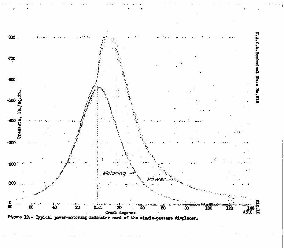
Typical indicator cards with and without air flow are shown for comparison in figures.12,' 13, and'14. All indi- cator cards show txo distinct rates?of-pre.ssure rise, al- though this characteristic is much more pronounced in the displacer combustion-chamber cards than in the quiescent combustion-chamber cards. The- maximum rate-of-pressure rise is about the same for all-three,, 50 pounds per sqiiaF'8 inch per degree at 1,500 r.p.m. The principal difference from the quiescent combustion-chamber cards is the charac- teristic early breakaway of both the displacer-power cards, believed to. be due.to the residual heat in the displacer.
Further work is planned to determine the optimum dis- placer height, the optimum fuel-spray formation, and the engine.performance-for.boosted and scavenged operation with. the optimum dtsplacer and,fuel spray.
. --
. 1. Air flow generated by the use of a displacer pis- ton can be used to increase the power output an,d to de- -.. .
- crease the spocifid fuel consumption of a hfgh-speed 4- stroke-cycle compression-ignition engine having a vertical disk form of combustion chamber. .--- . , I_ - .
2. The optimum maximum calculated air-flow speed was 7 .d times the linear speed of the cranl?in for t&e single-- ~ passage disslac-er and 8 times for the double-passage -dis- _- placer;
3. The double-passage displacer yas slightly superior to the s‘ingle-passage displacer with respect t.o engine per- formance and service.
4. Erosion or burning of the displacer or piston crown will not Be encountered if the displacer is-made in-- tegral with the piston.
5. The optimum fuel-valve nozzle developed for the quiescent-combustion chamber was also the optimum of the

. I . i
14 N.A.C.A. Technical Note No. 518 " / I
seme d.evelopment series for the double-passage displacer iE-! combusti.on chamber.
-=i I
Langley:Memorial Aeronautical Laboratory, National Advisory Committee for Aeronautics,
Langley Field, Va., January 22; 1935. .
:;..
REFERENCES : . c. . I,... .
1. kqore, C. S., and Collins, J. H., Jr.: Effect of . . Combustion-Chamber Shape on the Performance of a Prechamber Compression-Ignition Engine. T,h'.. No. 514, N.A.C.A., 1934.
I
L a
.-
I 2. Spanogle, J. A., and Foster, H. H.: Basic Require-
ments of Fuel-Injection Nozzles for Quiescent Combustion Chambers. T.N. NO. 382, IT.A.C.A., 1931. 't
3. B<chner, Dr.: The Fundamental Principles of High- . Sgeed Se&.-Diesel Engines. T.M. No. 358, F.A.C.A., I 1926. .
4. The Modern Diesel. Second Edit-ion, Iliffe and Sons Limited', Dorset House, Stamford St., London, 1933.
5. Heldt, P. M.: High-Speed Diesel Engines. First Edition, P. M. Heldt, Philadelphia, 1932.
6.' Spanogle, J. A., and Foster, H. H: Performance of a High-Speed Com-pression- Ignition .Engine Using Mul- tiple Orifice Fuel Injection Nozzles. T.H. No. 344, N.A.C.A., 1930.
7. Moore, C. S., and Collins, J. H., Jr.: Effect of Connecting-Passage Diameter on the Performance of a Compression-Ignition Engine with a Precombustion - Chamber. T.N. No. 436, N.A.C.A., 1932.
.
, .

I - I.A.O.A. feohaloal zote IO. 5l0 riga. a,4.6
I
I
l
i
Total paarsge area ln equmre inohrr (inclub lng olearanoaa)
is0 I
160 140 120 ord%g1e, 00. 80 40 00 degem r.:: rigure a.- BelrtioMhQ of sir-flow apeed to orank position and pse6a&e area during the
o~m'~resrlon etroke of a 5 M mgQle epeed, 1,500 r.p.n.;
7 engine with L l;)-lnoh oonneoting rod. dlsplaoer height, 1 Sfl6.inohea).
-100 0) : $0
140
Oaloulatedl
Figure 4.- Paaesgs width, inoh
Zffsot of pussage width ani injsotion-valve rigilrr 5.- Ooapariaon of
100st10n Oh olear-erhauat air nori f0rnemos rith 3
ne per- rithout
mng1r-pssesgs dieplscsr,1, em& M psrio y0a.
Z.P.E. . G3irLg1e-p.aage &trplaoer,1,500 r.p.m.1.

N.A.C.A. Techical Note No.618
.
Figure 3. (Side)
Figs. 3,6 -L
- .-
Figure 6.-Diagrammat ic rqxe- sentation of the
two-passage displacer air f 1 ow and fue 1 sprays.
10” B.T.C. \t /‘“IQ_1 tP
.gure 3.- Single-passage displacer com- bus t i on chamber.

. L -x . I
.
16
10
5Jo
em 40
703
BCQ
.

I I I I I I I I 1.0 a.0 a.0 4.01 104
hel qunntlty, lb.fayolr rlglm lo.- kffeotoffud quantltyoBmgi~
(xl/64 iMhps~:;, dimplsosr, l.zoo t.p...

H.A.C.A.
Fi .rl 2 \
Technical Note No, 518 X c;lGar &allst ~~SStandard fuel quantity
Fig. 11
160 1 I-.-l--7
140*$=-- t-i--+---t- -t-k====
iz$ .2. I Indidated 1
01
G 5 2 0
900 1100 1300 1500 17M Engine SpeGd, r.p.m.
Figure 11.- Effect of engine speed on performax8. (19/64 inch double-passage displacer).
bl L.
ail- ,, . 0...
-- -1 I L
,
l .* I . . . . , . ., l . . . c..
. .
.* .- .-. -
. .
. .
.1L. . .
,,’
*. . , ’
, . . .
l .;... . ‘.
. . . 5 .
-.. . . . * .* . . . . .
,

-,. . . . .
.‘..I
1.’
. . ‘.. . .
-..*
.., . . .
.
I :
..j ’
. ..” 0.
:. .: ..: * :. :.
.-.y Z:
; ‘:<;
.:’ .’
. .
. .
-.c . .
. . l .
. . .
. .
.
. .
. . . .
.*
..’ . .
*
. : c.. .’ .
. . . .!
_ : I
._ ,I., :
.I
* :
. . 1.

,’ .
.


![pcw 2011 Cut off - 58 - talentacademy.co.in · PSC- L.D ¢m¿°v ap≥h¿j tNmZy-t]-∏-dp-Iƒ Talent Academy hnP-b-tcJ {]kn-≤o-I-cWw TT T ALENT ALENT ALENT 57. Im°-\m-S≥ F∂](https://img.pdfslide.us/doc/110x75/5c9c7e1f09d3f23b2a8c0f6b/pcw-2011-cut-off-58-psc-ld-mv-aphj-tnmzy-t-dp-if-talent.jpg)