Embed Size (px)
Citation preview
Technologies Enabling Exploration of Skylights, Lava Tubes and Caves
NASA Innovative Advanced Concepts (NIAC) Phase I
FOR
OFFICE OF THE CHIEF TECHNOLOGIST
NATIONAL AERONAUTICS AND SPACE ADMINISTRATION
GRANT NUMBER: NNX11AR42G
AWARD DATE: SEPTEMBER 15, 2011
END DATE: SEPTEMBER 14, 2012
FINAL REPORT
BY
ASTROBOTIC TECHNOLOGY
4551 FORBES AVE #300
PITTSBURGH, PA 15213-3524
WILLIAM WHITTAKER, PRINCIPAL INVESTIGATOR
Abstract Robotic exploration of skylights and caves can seek out life, investigate geology and origins, and
open the subsurface of other worlds to humankind. However, exploration of these features is a
daunting venture. Planetary voids present perilous terrain that requires innovative technologies
for access, exploration, and modeling. This research developed technologies for venturing
underground and conceived mission architectures for robotic expeditions that explore skylights,
lava tubes and caves. The investigation identified effective designs for mobile robot architecture
to explore sub-planetary features. Results provide insight into mission architectures, skylight
reconnaissance and modeling, robot configuration and operations, and subsurface sensing and
modeling. These are developed as key enablers for robotic missions to explore planetary caves.
These results are compiled to generate “Spelunker”, a prototype mission concept to explore a
lunar skylight and cave. The Spelunker mission specifies safe landing on the rim of a skylight,
tethered descent of a power and communications hub, and autonomous cave exploration by
hybrid driving/hopping robots. A technology roadmap was generated identifying the maturation
path for enabling technologies for this and similar missions.
Table of Contents Abstract ........................................................................................................................................... 2
1 Introduction ............................................................................................................................. 1
1.1 What Is Known about Planetary Caves? .......................................................................... 2
1.2 Related Work.................................................................................................................... 5
2 Mission Concepts for Exploration of Skylights, Lava Tubes and Caves ................................ 6
2.1 Planetary Cave Insights That Impact Mission Architecture............................................. 7
2.2 Mission Architecture Issues and Options ......................................................................... 8
2.2.1 Mission Concept Details ........................................................................................... 9
3 Skylight Reconnaissance and Modeling ................................................................................ 12
3.1 Skylight Simulation Environment .................................................................................. 12
3.2 Complementary Flyover and Surface Modeling for Skylight Reconnaissance ............. 14
3.2.1 Complementary Flyover and Surface Modeling Experiments ............................... 15
3.2.2 Methods for Stitching Lander and Rover Models................................................... 18
4 Robot Configuration and Operations ..................................................................................... 20
4.1 Configuration Selection.................................................................................................. 20
4.1.1 Access and In-Cave Mobility.................................................................................. 21
4.1.2 Power and Communication Configuration ............................................................. 21
4.1.3 Autonomy and Control ........................................................................................... 21
4.2 Configuration Development and Trade Study ............................................................... 21
4.3 Selected Configuration ................................................................................................... 25
4.3.1 Access and Mobility ............................................................................................... 25
4.3.2 Power and Communication Configuration ............................................................. 27
4.3.3 Autonomy and Control ........................................................................................... 28
5 Subsurface Sensing and Modeling ........................................................................................ 32
5.1 Design for Planetary Cave Sensing ................................................................................ 32
5.2 High Quality 3D Model Building by Fusion of Range and Imaging Sensors................ 33
5.3 Lunar Cave Analog Modeling Experiment .................................................................... 37
5.3.1 Modeling Results from Analog Experimentation ................................................... 40
6 Technology Roadmap ............................................................................................................ 42
7 References ............................................................................................................................. 44

Technologies Enabling Exploration of Skylights, Lava Tubes and Caves
Final Report for Contract # NNX11AR42G
Astrobotic Technology, Inc - Confidential 1
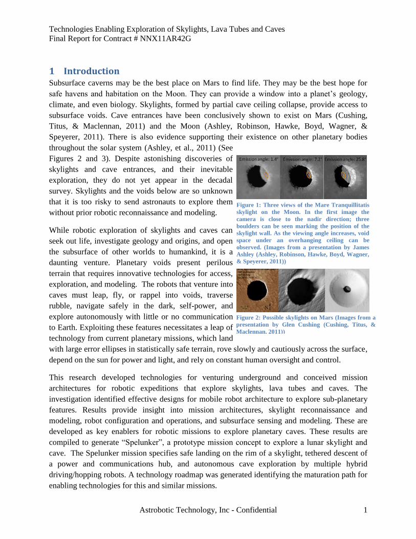
1 Introduction Subsurface caverns may be the best place on Mars to find life. They may be the best hope for
safe havens and habitation on the Moon. They can provide a window into a planet’s geology,
climate, and even biology. Skylights, formed by partial cave ceiling collapse, provide access to
subsurface voids. Cave entrances have been conclusively shown to exist on Mars (Cushing,
Titus, & Maclennan, 2011) and the Moon (Ashley, Robinson, Hawke, Boyd, Wagner, &
Speyerer, 2011). There is also evidence supporting their existence on other planetary bodies
throughout the solar system (Ashley, et al., 2011) (See
Figures 2 and 3). Despite astonishing discoveries of
skylights and cave entrances, and their inevitable
exploration, they do not yet appear in the decadal
survey. Skylights and the voids below are so unknown
that it is too risky to send astronauts to explore them
without prior robotic reconnaissance and modeling.
While robotic exploration of skylights and caves can
seek out life, investigate geology and origins, and open
the subsurface of other worlds to humankind, it is a
daunting venture. Planetary voids present perilous
terrain that requires innovative technologies for access,
exploration, and modeling. The robots that venture into
caves must leap, fly, or rappel into voids, traverse
rubble, navigate safely in the dark, self-power, and
explore autonomously with little or no communication
to Earth. Exploiting these features necessitates a leap of
technology from current planetary missions, which land
with large error ellipses in statistically safe terrain, rove slowly and cautiously across the surface,
depend on the sun for power and light, and rely on constant human oversight and control.
This research developed technologies for venturing underground and conceived mission
architectures for robotic expeditions that explore skylights, lava tubes and caves. The
investigation identified effective designs for mobile robot architecture to explore sub-planetary
features. Results provide insight into mission architectures, skylight reconnaissance and
modeling, robot configuration and operations, and subsurface sensing and modeling. These are
developed as key enablers for robotic missions to explore planetary caves. These results are
compiled to generate “Spelunker”, a prototype mission concept to explore a lunar skylight and
cave. The Spelunker mission specifies safe landing on the rim of a skylight, tethered descent of
a power and communications hub, and autonomous cave exploration by multiple hybrid
driving/hopping robots. A technology roadmap was generated identifying the maturation path for
enabling technologies for this and similar missions.
Figure 1: Three views of the Mare Tranquillitatis
skylight on the Moon. In the first image the
camera is close to the nadir direction; three
boulders can be seen marking the position of the
skylight wall. As the viewing angle increases, void
space under an overhanging ceiling can be
observed. (Images from a presentation by James
Ashley (Ashley, Robinson, Hawke, Boyd, Wagner,
& Speyerer, 2011))
Figure 2: Possible skylights on Mars (Images from a
presentation by Glen Cushing (Cushing, Titus, &
Maclennan, 2011))
Technologies Enabling Exploration of Skylights, Lava Tubes and Caves
Final Report for Contract # NNX11AR42G
Astrobotic Technology, Inc - Confidential 2
1.1 What Is Known about Planetary Caves? Before caves were known to exist on planetary bodies beyond Earth,
scientists looked at caves on Earth and hypothesized that similar
features might exist elsewhere. Even now, when caves have been
proven to exist on the Moon and Mars, Earth analogs are one of the
best sources of information about planetary caves as satellites provide
limited and low-resolution views into subsurface features. Known
mechanisms for cave formation on Earth are likely to form caves on
other planets as well. These mechanisms include lava flows, volcano-
tectonic fractures, and chemical dissolution.
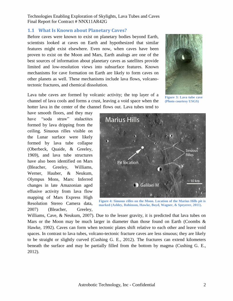
Lava tube caves are formed by volcanic activity; the top layer of a
channel of lava cools and forms a crust, leaving a void space when the
hotter lava in the center of the channel flows out. Lava tubes tend to
have smooth floors, and they may
have “soda straw” stalactites
formed by lava dripping from the
ceiling. Sinuous rilles visible on
the Lunar surface were likely
formed by lava tube collapse
(Oberbeck, Quaide, & Greeley,
1969), and lava tube structures
have also been identified on Mars
(Bleacher, Greeley, Williams,
Werner, Hauber, & Neukum,
Olympus Mons, Mars: Inferred
changes in late Amazonian aged
effusive activity from lava flow
mapping of Mars Express High
Resolution Stereo Camera data,
2007) (Bleacher, Greeley,
Williams, Cave, & Neukum, 2007). Due to the lesser gravity, it is predicted that lava tubes on
Mars or the Moon may be much larger in diameter than those found on Earth (Coombs &
Hawke, 1992). Caves can form when tectonic plates shift relative to each other and leave void
spaces. In contrast to lava tubes, volcano-tectonic fracture caves are less sinuous; they are likely
to be straight or slightly curved (Cushing G. E., 2012). The fractures can extend kilometers
beneath the surface and may be partially filled from the bottom by magma (Cushing G. E.,
2012).
Figure 3: Lava tube cave
(Photo courtesy USGS)
Figure 4: Sinuous rilles on the Moon. Location of the Marius Hills pit is
marked (Ashley, Robinson, Hawke, Boyd, Wagner, & Speyerer, 2011).
Technologies Enabling Exploration of Skylights, Lava Tubes and Caves
Final Report for Contract # NNX11AR42G
Astrobotic Technology, Inc - Confidential 3
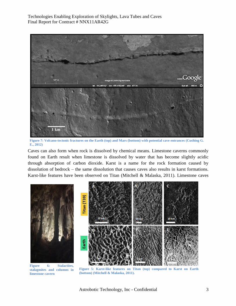
Caves can also form when rock is dissolved by chemical means. Limestone caverns commonly
found on Earth result when limestone is dissolved by water that has become slightly acidic
through absorption of carbon dioxide. Karst is a name for the rock formation caused by
dissolution of bedrock – the same dissolution that causes caves also results in karst formations.
Karst-like features have been observed on Titan (Mitchell & Malaska, 2011). Limestone caves
Figure 7: Volcano-tectonic fractures on the Earth (top) and Mars (bottom) with potential cave entrances (Cushing G.
E., 2012)
Figure 5: Karst-like features on Titan (top) compared to Karst on Earth
(bottom) (Mitchell & Malaska, 2011).
Figure 6: Stalactites,
stalagmites and columns in
limestone cavern
Technologies Enabling Exploration of Skylights, Lava Tubes and Caves
Final Report for Contract # NNX11AR42G
Astrobotic Technology, Inc - Confidential 4
on Earth tend to include sequences of chambers at many
different levels, as opposed to the long, continuous, gently-
sloping caverns in lava tubes. They often have many stalactites
and stalagmites, formed when minerals are deposited by the
flow of the dissolving liquid.
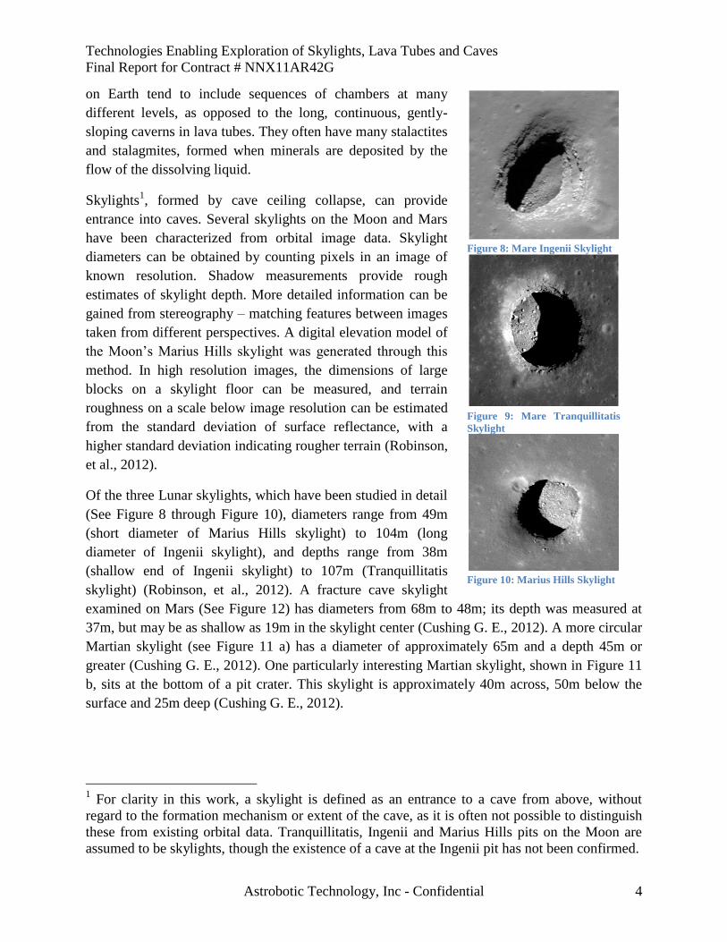
Skylights1, formed by cave ceiling collapse, can provide
entrance into caves. Several skylights on the Moon and Mars
have been characterized from orbital image data. Skylight
diameters can be obtained by counting pixels in an image of
known resolution. Shadow measurements provide rough
estimates of skylight depth. More detailed information can be
gained from stereography – matching features between images
taken from different perspectives. A digital elevation model of
the Moon’s Marius Hills skylight was generated through this
method. In high resolution images, the dimensions of large
blocks on a skylight floor can be measured, and terrain
roughness on a scale below image resolution can be estimated
from the standard deviation of surface reflectance, with a
higher standard deviation indicating rougher terrain (Robinson,
et al., 2012).
Of the three Lunar skylights, which have been studied in detail
(See Figure 8 through Figure 10), diameters range from 49m
(short diameter of Marius Hills skylight) to 104m (long
diameter of Ingenii skylight), and depths range from 38m
(shallow end of Ingenii skylight) to 107m (Tranquillitatis
skylight) (Robinson, et al., 2012). A fracture cave skylight
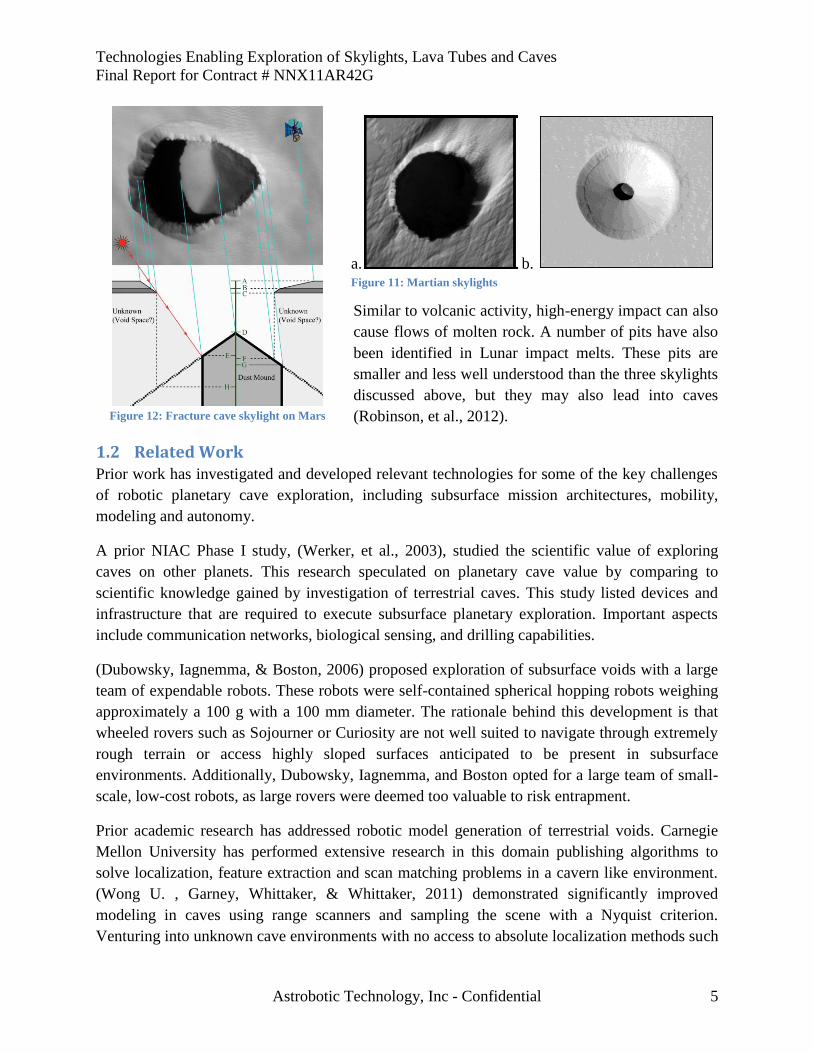
examined on Mars (See Figure 12) has diameters from 68m to 48m; its depth was measured at
37m, but may be as shallow as 19m in the skylight center (Cushing G. E., 2012). A more circular
Martian skylight (see Figure 11 a) has a diameter of approximately 65m and a depth 45m or
greater (Cushing G. E., 2012). One particularly interesting Martian skylight, shown in Figure 11
b, sits at the bottom of a pit crater. This skylight is approximately 40m across, 50m below the
surface and 25m deep (Cushing G. E., 2012).
1 For clarity in this work, a skylight is defined as an entrance to a cave from above, without
regard to the formation mechanism or extent of the cave, as it is often not possible to distinguish
these from existing orbital data. Tranquillitatis, Ingenii and Marius Hills pits on the Moon are
assumed to be skylights, though the existence of a cave at the Ingenii pit has not been confirmed.
Figure 8: Mare Ingenii Skylight
Figure 9: Mare Tranquillitatis
Skylight
Figure 10: Marius Hills Skylight
Technologies Enabling Exploration of Skylights, Lava Tubes and Caves
Final Report for Contract # NNX11AR42G
Astrobotic Technology, Inc - Confidential 5
Similar to volcanic activity, high-energy impact can also
cause flows of molten rock. A number of pits have also
been identified in Lunar impact melts. These pits are
smaller and less well understood than the three skylights
discussed above, but they may also lead into caves
(Robinson, et al., 2012).
1.2 Related Work Prior work has investigated and developed relevant technologies for some of the key challenges
of robotic planetary cave exploration, including subsurface mission architectures, mobility,
modeling and autonomy.
A prior NIAC Phase I study, (Werker, et al., 2003), studied the scientific value of exploring
caves on other planets. This research speculated on planetary cave value by comparing to
scientific knowledge gained by investigation of terrestrial caves. This study listed devices and
infrastructure that are required to execute subsurface planetary exploration. Important aspects
include communication networks, biological sensing, and drilling capabilities.
(Dubowsky, Iagnemma, & Boston, 2006) proposed exploration of subsurface voids with a large
team of expendable robots. These robots were self-contained spherical hopping robots weighing
approximately a 100 g with a 100 mm diameter. The rationale behind this development is that
wheeled rovers such as Sojourner or Curiosity are not well suited to navigate through extremely
rough terrain or access highly sloped surfaces anticipated to be present in subsurface
environments. Additionally, Dubowsky, Iagnemma, and Boston opted for a large team of small-
scale, low-cost robots, as large rovers were deemed too valuable to risk entrapment.
Prior academic research has addressed robotic model generation of terrestrial voids. Carnegie
Mellon University has performed extensive research in this domain publishing algorithms to
solve localization, feature extraction and scan matching problems in a cavern like environment.
(Wong U. , Garney, Whittaker, & Whittaker, 2011) demonstrated significantly improved
modeling in caves using range scanners and sampling the scene with a Nyquist criterion.
Venturing into unknown cave environments with no access to absolute localization methods such
Figure 12: Fracture cave skylight on Mars
a. b. Figure 11: Martian skylights
Technologies Enabling Exploration of Skylights, Lava Tubes and Caves
Final Report for Contract # NNX11AR42G
Astrobotic Technology, Inc - Confidential 6
as GPS, a robot must solve the Simultaneous Localization and Mapping (SLAM) problem.
Fairfield, Kantor and Wettergreen presented approaches for SLAM applied to a robot exploring
underwater caves (Fairfield, Kantor, & Wettergreen, Three Dimensional Evidence Grids for
SLAM in Complex Underwater Environments, 2005) (Fairfield, Kantor, & Wettergreen, 2006)
(Fairfield, Kantor, & Wettergreen, 2007; Fairfield, Kantor, & Wettergreen, Segmented SLAM in
Three-Dimensional Environments, 2010).Robot motion on natural surfaces has to cope with
changing yaw, pitch and roll angles, making pose estimation a problem in six mathematical
dimensions. (Nuchter & Surmann, 2004) developed a fast variant of the Iterative Closest Points
algorithm that registers 3D scans in a common coordinate system and re-localizes the robot.
Consistent 3D maps can then be generated using a global relaxation. Zlot and Bosse coupled
measurements from a spinning, scanning LIDAR with data from an inertial measurement unit to
achieve SLAM from a moving platform that built a 3D model for 17km of mine tunnel (Zlot &
Bosse, 2012). Prior work also encompasses planning for subterranean exploration and mapping
(Morris, Ferguson, Silver, & Thayer, 2006) (Thrun, et al., 2004), and science autonomy
(Wagner, Apostolopoulos, Shillcutt, Shamah, Simmons, & Whittaker, 2001) (Wettergreen, et al.,
2005).
2 Mission Concepts for Exploration of Skylights, Lava Tubes and Caves
For the purposes of this study, mission architecture includes the number of robotic entities and
their roles (i.e. a single probe that descends to the planetary surface and flies into a skylight, a
lander that deploys a rover to explore a cave, etc.), the approximate mass of each entity (which
has implications on the traditional space mission architecture components of launch vehicle and
trajectory), the methods of communication, the power strategies employed, and the concept of
operations. Multi-mission architectures are also possibilities for skylight and cave exploration.
One such multi-mission architecture would be broken into three phases, the first phase being the
flyover and surface investigation of a skylight and deployment of a sensor package to a skylight
Phase I Investigation of Skylight Access
Analysis of mission requirements and configurations. Precision landing analysis. Participated in 2011
International Planetary Caves Workshop.
Phase I Insights
Ground-penetrating radar fails to detect lava tubes where lava is laid down in multiple flows, making it
necessary to descend into a lava tube to measure its extent.
Safe, autonomous landings near features can be achieved without guaranteed-safe zones of landing-ellipse
size, using terrain relative navigation in combination with existing hazard detection and avoidance
technology.
A combination of multiple untethered cave exploration robots that can leap into the hole plus a tethered
robot for a line-of-sight comm link is the current best configuration for skylight entry and exploration.
Indications for Phase II Study
Detail Spelunker mission concept.
A tethered power and communications node lowered into a skylight enables robots to recharge and
communicate data to ground control without requiring the mobility to return to the surface.
Wireless power and data transmission within line-of-sight of a communications node eliminate the need
for exploration robots to reach the tethered node, which is critical in unpredictable environments where the
tether end may be located in a rubble pile or similarly difficult terrain.
Implications for Phase II Study
Develop Spelunker mission concept around the above configuration.
Technologies Enabling Exploration of Skylights, Lava Tubes and Caves
Final Report for Contract # NNX11AR42G
Astrobotic Technology, Inc - Confidential 7
entrance. This sensor package would be lowered into the skylight and scan the portion of the lava
tube within sensor range, providing valuable insight about the environment within the tube. The
second phase sends mobile robots in to explore the lava tube or cave network. The third phase
includes delivery of habitats, robots, and personnel to the tube for base construction, the
exploitation of resources, or the deployment of a robot with specialized scientific instruments to
investigate the findings from the previous phases. Recognizing that economic and political
realities sometimes make it difficult to send multiple missions to explore the same target,
architectures developed in this study combined phases one and two into a single mission and
further details this combined mission. In order to compare mission architectures, a reference set
of mission goals are defined. For this study, those goals are to: enter a lava tube cave via a
skylight, explore the cave, and send back data that includes a model of the skylight and cave.
2.1 Planetary Cave Insights That Impact Mission Architecture Through this research, Astrobotic participated in the Planetary Cave Research Workshop,
discussion with scientists at this workshop provided valuable insights for cave exploration
mission architectures as detailed in this section.
Ground penetrating radar, which can be used on Earth to determine the extent of a subterranean
cavern from the surface, often fails to detect lava tubes if the lava was deposited in multiple
flows. This is because ground penetrating radar partially reflects at interfaces between layers of
material, and repeated lava flows result in many layers of material close to the surface.
Science objectives are also important to consider when planning what parts of the cave to
investigate, what sensors are required, and how far a robot must travel inside a cave to gather
useful data. For caves on Earth, floors are of particular interest in lava tubes, but walls and
ceilings are more interesting in other types of caves. The distance that must be traveled inside a
cave to observe a regime that is significantly different from a science perspective is highly
dependent on morphology, but in many cases it may be sufficient to get beyond the “twilight
zone,” which is the transition between areas that are illuminated for some period during the day
as the sun transits overhead, and areas of constant darkness. This region is likely to be indicative
of the variation within the tube in terms of potential to support life, volatile contents, and
geological features, which may be impacted by sunlight, temperature variations, or rock fall
during skylight formation.
Additionally, concern was raised by some scientists about the use of propulsive vehicles in and
around skylights and caves. If volatiles exist trapped at the bottom of a skylight, they could be
contaminated by a vehicle’s thruster plume. Similarly, living organisms inside a cave could be
killed if a vehicle’s thruster plume contained toxic chemicals. Mission architectures for
exploration of skylights, caves and lava tubes must consider both the value of information gained
by using a given exploration strategy and the possibility of contaminating scientifically important
sites with that strategy.
Technologies Enabling Exploration of Skylights, Lava Tubes and Caves
Final Report for Contract # NNX11AR42G
Astrobotic Technology, Inc - Confidential 8
2.2 Mission Architecture Issues and Options There are five main issues that any mission for planetary cave exploration must address: access
to the cave, in-cave mobility, collection and processing of data for modeling and other scientific
objectives, power, and communication. Robot configuration (discussed in Section 4) has a large
impact on how these issues are addressed, but mission architecture plays an important and
complementary role. How many robots are there, and how do they work together? What tasks are
robots commanded to perform? In this study, the space of missions architectures explored
includes more than one robot (i.e. the lander that reaches the planetary surface is not the only
entity) and less than many (i.e., not hundreds or thousands of entities).
Even with lower gravity on order of one sixth (Moon) or one third (Mars) of Earth’s, planetary
bodies are still substantial gravity wells, and precision propulsive landing requires significant
fuel. Cave exploration requires power-conscious mission architecture, due to the lack of solar
power underground. Energetically, it does not make sense to carry the propulsion system
required for landing along for further cave exploration activities. While a braking stage might
simply be discarded as a lander nears the ground, this mass could also dual-purpose as an anchor
for tethered descent and/or a communications relay. Lander solar panels that provided power in
cruise can also be re-purposed to perform tethered re-charging for the cave explorer.
Dubowsky and Boston proposed a many-robot architecture (Dubowsky, Iagnemma, & Boston,
2006). In this approach, many baseball-sized robots descend into a cave. Communication is
achieved by relay between agents. This method is robust to the failure of one or even the
majority of the robots. If a few manage to succeed, the mission succeeds. The downside of this
many-robot architecture is that the robots must be very small, (in mass and volume), and very
cheap in order for the mission to be feasible. Unfortunately, the extremes of small size and low
cost often come with limited capability. Miniaturization has steadily decreased the size of robot
components over time. Boston and Dubowsky count on this trend continuing, until 0.1kg
microbots could be achieved within 10-40 years, but sometimes miniaturization runs up against
physical limits. For example, chip manufacturers faced new issues when silicon gates reached a
thickness of only a few atoms. Modeling in lava tubes requires active sensing, and due to the
expected larger size of lava tubes on the Moon and Mars, sensors in these environments must
have long range, which requires increased power. Technologies like active sensing may well
provide a physical barrier to miniaturization.
Given 100kg of payload capacity, a lander could deploy 10 robots at 10kg each, versus 1000
robots at 0.1kg each. These approaches require equivalent mass. They could cover equivalent
areas, with each 10kg robot traveling farther in its lifetime than each 0.1kg robot. But, if the
0.1kg robot can accommodate a sensor with 1m range and the 10kg robot can accommodate a
sensor with 100m range, only one of these approaches can model a 100m-high cave ceiling. The
concept of relatively small but sufficiently capable robots drives the mission architectures
explored in this work.
Technologies Enabling Exploration of Skylights, Lava Tubes and Caves
Final Report for Contract # NNX11AR42G
Astrobotic Technology, Inc - Confidential 9
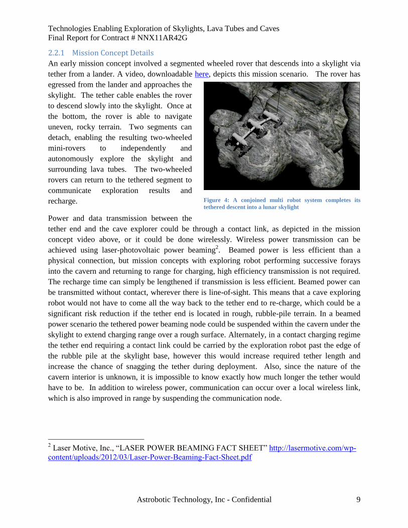
Figure 4: A conjoined multi robot system completes its
tethered descent into a lunar skylight
2.2.1 Mission Concept Details
An early mission concept involved a segmented wheeled rover that descends into a skylight via
tether from a lander. A video, downloadable here, depicts this mission scenario. The rover has
egressed from the lander and approaches the
skylight. The tether cable enables the rover
to descend slowly into the skylight. Once at
the bottom, the rover is able to navigate
uneven, rocky terrain. Two segments can
detach, enabling the resulting two-wheeled
mini-rovers to independently and
autonomously explore the skylight and
surrounding lava tubes. The two-wheeled
rovers can return to the tethered segment to
communicate exploration results and
recharge.
Power and data transmission between the
tether end and the cave explorer could be through a contact link, as depicted in the mission
concept video above, or it could be done wirelessly. Wireless power transmission can be
achieved using laser-photovoltaic power beaming2. Beamed power is less efficient than a
physical connection, but mission concepts with exploring robot performing successive forays
into the cavern and returning to range for charging, high efficiency transmission is not required.
The recharge time can simply be lengthened if transmission is less efficient. Beamed power can
be transmitted without contact, wherever there is line-of-sight. This means that a cave exploring
robot would not have to come all the way back to the tether end to re-charge, which could be a
significant risk reduction if the tether end is located in rough, rubble-pile terrain. In a beamed
power scenario the tethered power beaming node could be suspended within the cavern under the
skylight to extend charging range over a rough surface. Alternately, in a contact charging regime
the tether end requiring a contact link could be carried by the exploration robot past the edge of
the rubble pile at the skylight base, however this would increase required tether length and
increase the chance of snagging the tether during deployment. Also, since the nature of the
cavern interior is unknown, it is impossible to know exactly how much longer the tether would
have to be. In addition to wireless power, communication can occur over a local wireless link,
which is also improved in range by suspending the communication node.
2 Laser Motive, Inc., “LASER POWER BEAMING FACT SHEET” http://lasermotive.com/wp-
content/uploads/2012/03/Laser-Power-Beaming-Fact-Sheet.pdf

Technologies Enabling Exploration of Skylights, Lava Tubes and Caves
Final Report for Contract # NNX11AR42G
Astrobotic Technology, Inc - Confidential 10
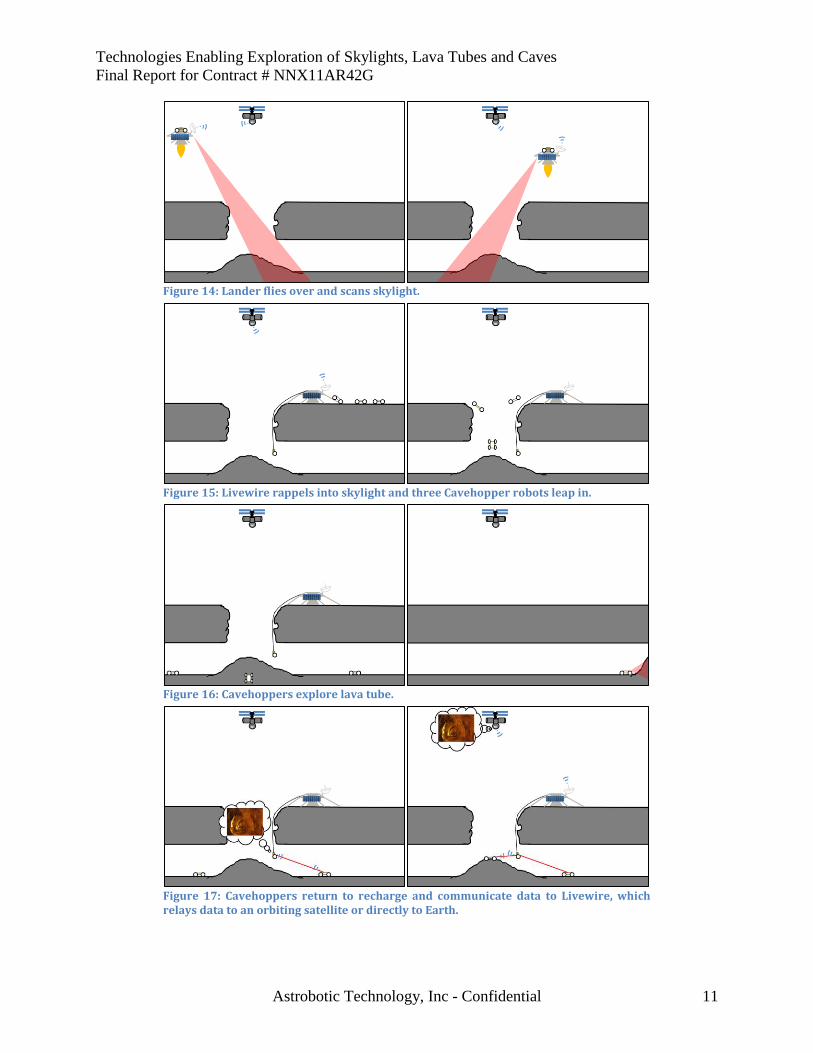
A mission concept for a prototypical mission to a lunar skylight and lava tube entitled
“Spelunker” is presented below and in Figure 14 through Figure 17. The mission includes a
cave mobility robot entitled “Cavehopper”, a hybrid driving/hopping robot (See Figure 13). The
selection Cavehopper as a promising robot configuration is detailed in Section 4.
Spelunker delivers three Cavehopper robots to the lunar surface, where they hop into a planetary
lava tube via a skylight, autonomously explore using a suite of onboard sensors, and send back
detailed models of the cave interior via a tethered power and comm station. This mission
concept is applicable to the Moon, Mars, and any other planetary body with skylights visible
from orbit. Reconfiguration of onboard sensing can adapt the mission to specialized scientific
investigation.
The Spelunker mission deploys a propulsive lander that flies over the skylight during descent,
scanning the terrain with LIDAR and capturing reconnaissance imagery. The lander
autonomously evaluates the terrain for hazards and chooses a landing spot based on safety and
on favorability of the adjacent wall for tethered descent. After landing, three Cavehopper robots
egress from the lander. A fourth robot, “Livewire,” makes a tethered descent into the hole.
Livewire brings a connection to the lander’s radio, the capability to beam power, and camera and
LIDAR sensors to provide reconnaissance and track Cavehopper robots. After analysis of
Livewire’s reconnaissance data, ground control operators select entry points around the skylight
rim for the three Cavehoppers. The Cavehoppers, powered by batteries, launch themselves into
the skylight. They hop to navigate rubble on the skylight floor,
and use wheels to drive when they encounter smooth floor. Inside
the cave, the Cavehoppers receive high-level mission direction
from human operators but are capable of autonomously planning
and executing exploratory traverses beyond Livewire’s
communication range. While driving and hopping, the
Cavehoppers model their environment using cameras with active
lighting and LIDAR sensing. They also carry miniaturized
science instruments to investigate cave geology. The
Cavehoppers return to within line-of-sight of the Livewire to
relay their data and recharge from beamed power. Livewire
transmits the Cavehoppers’ data up the tether to an antenna on the
lander, which transmits to a relay satellite or directly to Earth.
This foray-”phone home” cycle is repeated until all lava tube
regions within battery range of the skylight have been explored.
Scientific investigation of targets of interest can continue until the
robots exhaust their operational life.
Figure 13: “Cavehopper”, a hybrid driving/hopping robot for planetary cave exploration.
Technologies Enabling Exploration of Skylights, Lava Tubes and Caves
Final Report for Contract # NNX11AR42G
Astrobotic Technology, Inc - Confidential 11
Figure 14: Lander flies over and scans skylight.
Figure 15: Livewire rappels into skylight and three Cavehopper robots leap in.
Figure 16: Cavehoppers explore lava tube.
Figure 17: Cavehoppers return to recharge and communicate data to Livewire, which relays data to an orbiting satellite or directly to Earth.
Technologies Enabling Exploration of Skylights, Lava Tubes and Caves
Final Report for Contract # NNX11AR42G
Astrobotic Technology, Inc - Confidential 12
3 Skylight Reconnaissance and Modeling
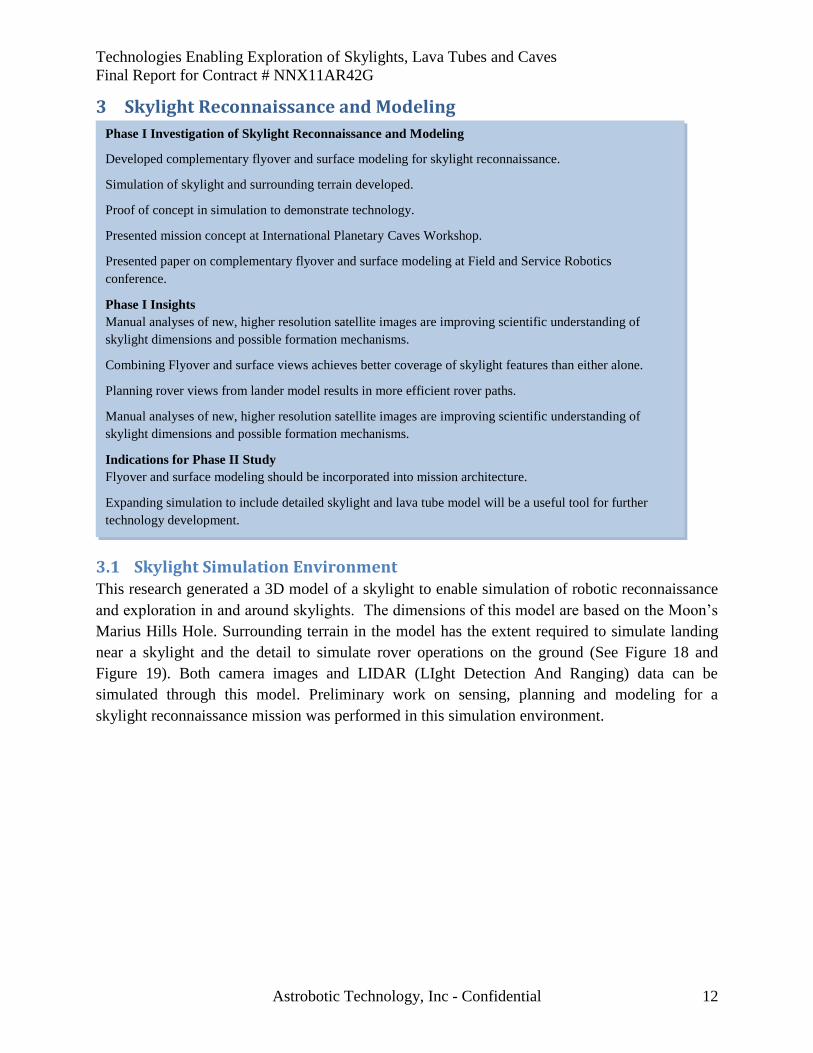
3.1 Skylight Simulation Environment This research generated a 3D model of a skylight to enable simulation of robotic reconnaissance
and exploration in and around skylights. The dimensions of this model are based on the Moon’s
Marius Hills Hole. Surrounding terrain in the model has the extent required to simulate landing
near a skylight and the detail to simulate rover operations on the ground (See Figure 18 and
Figure 19). Both camera images and LIDAR (LIght Detection And Ranging) data can be
simulated through this model. Preliminary work on sensing, planning and modeling for a
skylight reconnaissance mission was performed in this simulation environment.
Phase I Investigation of Skylight Reconnaissance and Modeling
Developed complementary flyover and surface modeling for skylight reconnaissance.
Simulation of skylight and surrounding terrain developed.
Proof of concept in simulation to demonstrate technology.
Presented mission concept at International Planetary Caves Workshop.
Presented paper on complementary flyover and surface modeling at Field and Service Robotics
conference.
Phase I Insights
Manual analyses of new, higher resolution satellite images are improving scientific understanding of
skylight dimensions and possible formation mechanisms.
Combining Flyover and surface views achieves better coverage of skylight features than either alone.
Planning rover views from lander model results in more efficient rover paths.
Manual analyses of new, higher resolution satellite images are improving scientific understanding of
skylight dimensions and possible formation mechanisms.
Indications for Phase II Study
Flyover and surface modeling should be incorporated into mission architecture.
Expanding simulation to include detailed skylight and lava tube model will be a useful tool for further
technology development.
Technologies Enabling Exploration of Skylights, Lava Tubes and Caves
Final Report for Contract # NNX11AR42G
Astrobotic Technology, Inc - Confidential 13
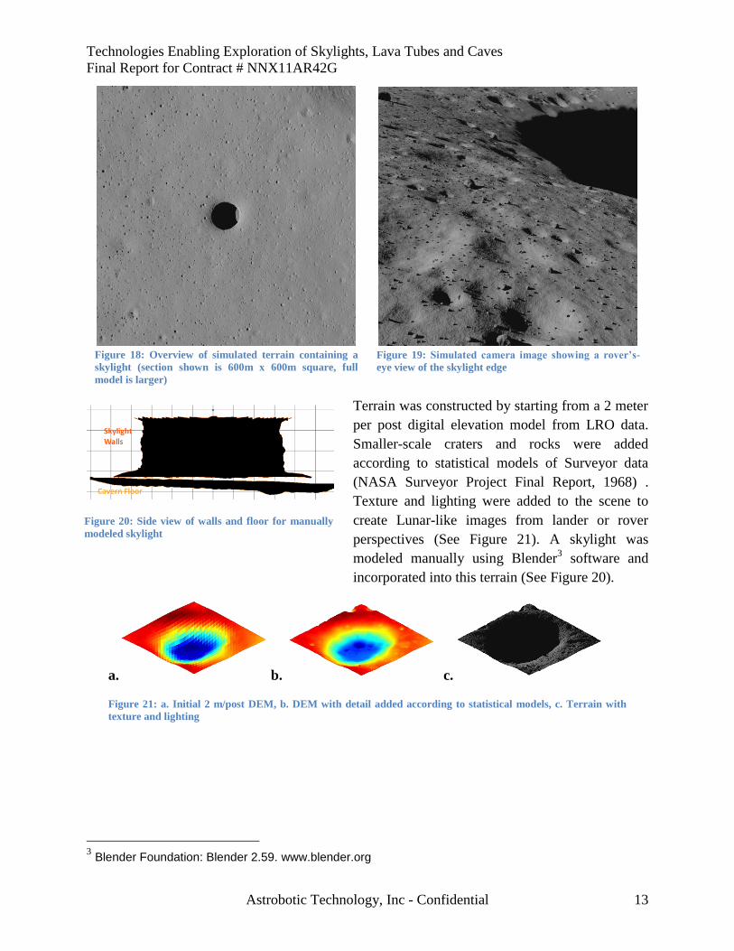
Terrain was constructed by starting from a 2 meter
per post digital elevation model from LRO data.
Smaller-scale craters and rocks were added
according to statistical models of Surveyor data
(NASA Surveyor Project Final Report, 1968) .
Texture and lighting were added to the scene to
create Lunar-like images from lander or rover
perspectives (See Figure 21). A skylight was
modeled manually using Blender3 software and
incorporated into this terrain (See Figure 20).
3 Blender Foundation: Blender 2.59. www.blender.org
a. b. c.
Figure 21: a. Initial 2 m/post DEM, b. DEM with detail added according to statistical models, c. Terrain with
texture and lighting
Figure 19: Simulated camera image showing a rover’s-
eye view of the skylight edge
Figure 18: Overview of simulated terrain containing a
skylight (section shown is 600m x 600m square, full
model is larger)
Figure 20: Side view of walls and floor for manually
modeled skylight
Technologies Enabling Exploration of Skylights, Lava Tubes and Caves
Final Report for Contract # NNX11AR42G
Astrobotic Technology, Inc - Confidential 14
3.2 Complementary Flyover and Surface Modeling for Skylight Reconnaissance
Because skylights are so new and so unknown, it is much too risky to send astronauts, or even
complex and expensive robotic systems, to explore these holes and the caverns below without
prior reconnaissance. Surface robots can approach a skylight and scan the walls, but skylight
geometry precludes viewing the floor of the hole from a surface perspective. This research
innovated an autonomous mission strategy for skylight reconnaissance that integrates lander and
rover exploration. Autonomy will make such missions feasible even in locations with limited
communications, such as the Lunar far side or the moons of the outer planets.
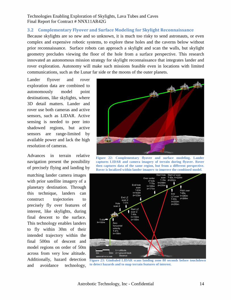
Lander flyover and rover
exploration data are combined to
autonomously model point
destinations, like skylights, where
3D detail matters. Lander and
rover use both cameras and active
sensors, such as LIDAR. Active
sensing is needed to peer into
shadowed regions, but active
sensors are range-limited by
available power and lack the high
resolution of cameras.
Advances in terrain relative
navigation present the possibility
of precisely flying and landing by
matching lander camera images
with prior satellite imagery of a
planetary destination. Through
this technique, landers can
construct trajectories to
precisely fly over features of
interest, like skylights, during
final descent to the surface.
This technology enables landers
to fly within 30m of their
intended trajectory within the
final 500m of descent and
model regions on order of 50m
across from very low altitude.
Additionally, hazard detection
and avoidance technology,
Figure 23: Gimbaled LIDAR scans landing zone 80 seconds before touchdown
to detect hazards and to map terrain features of interest.
Figure 22: Complementary flyover and surface modeling. Lander
captures LIDAR and camera imagery of terrain during flyover. Rover
then captures data of the same region, but from a different perspective.
Rover is localized within lander imagery to improve the combined model.
Technologies Enabling Exploration of Skylights, Lava Tubes and Caves
Final Report for Contract # NNX11AR42G
Astrobotic Technology, Inc - Confidential 15
combined with precise navigation, enables safe and autonomous landings near features even
without guaranteed-safe zones of landing-ellipse size.
Rover modeling begins at the lander touchdown location, providing a common tie-point between
surface and flyover models. Lander-generated surface model is used by the rover planer to
enhance safety during traverse. Rover paths and sensor views can be autonomously selected,
using a “next best view” approach, to fill holes in the lander-generated surface model and
generate a higher fidelity and coverage combined model. Lander-generated model also improves
rover localization, correcting the drift of visual odometry and other relative navigation methods.
Lander flyover captures detailed overview data, as well as perspectives that cannot be observed
from a rover viewpoint. Rovers can capture close-up images of the terrain, and they can linger to
capture multiple views from stationary locations, though always from low, grazing perspectives.
Alternately, landers can acquire bird’s-eye views but with less detail and resolution since their
one-pass, always-moving trajectories are constrained by fuel limitations. Combining lander and
rover data enables autonomous construction of high-quality 3D models of skylights, not possible
from either platform alone.
A mission concept for flyover and surface exploration of a skylight was presented at the First
International Planetary Caves Workshop (Peterson, Jones, & Whittaker, 2011). This included
preliminary sensor selection and timing for scanning a skylight while flying over in the final
stages of descent to a planetary body, as shown in Figure 23. Further analysis of the concept,
including experiments using the simulation presented in Section 3.1, was presented in a paper at
the 8th
International Conference on Field and Service Robotics (Jones, Wong, Peterson, Koenig,
Sheshadri, & Whittaker, 2012). This analysis is presented in later in this section
3.2.1 Complementary Flyover and Surface Modeling Experiments
To test the approach, camera and LIDAR data from both lander and rover perspectives are
generated in simulation. Lander-only models, rover-only models and combined lander and rover
models are constructed. Because the sensed terrain is simulated, exact ground truth for 3D
structure is known, facilitating comparison between models. Coverage values for these three
cases were compared.
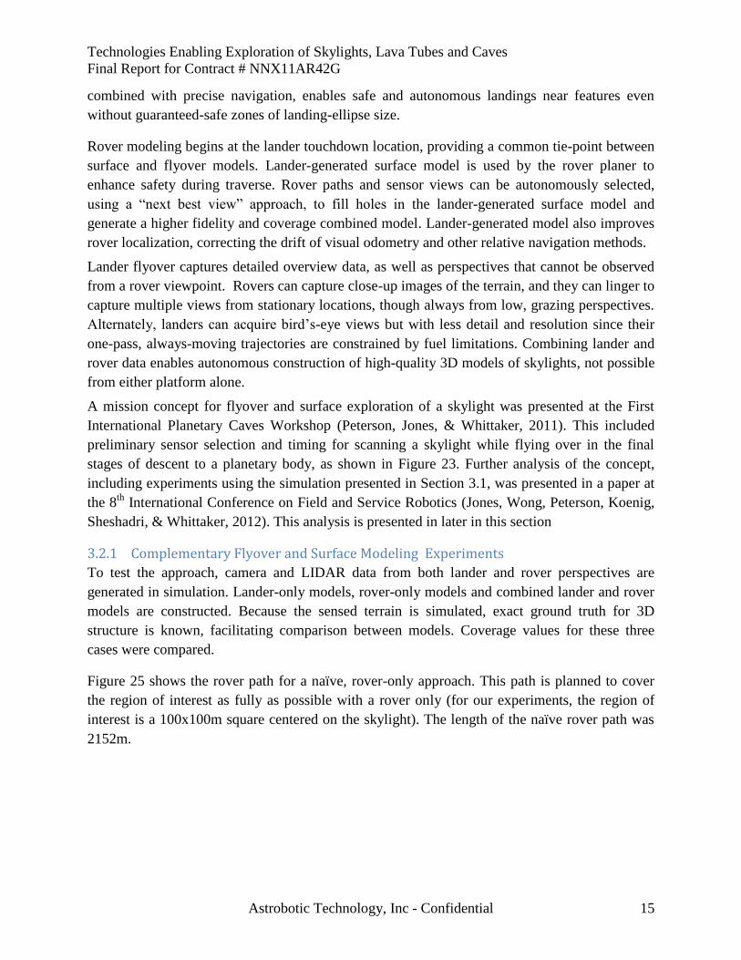
Figure 25 shows the rover path for a naïve, rover-only approach. This path is planned to cover
the region of interest as fully as possible with a rover only (for our experiments, the region of
interest is a 100x100m square centered on the skylight). The length of the naïve rover path was
2152m.
Technologies Enabling Exploration of Skylights, Lava Tubes and Caves
Final Report for Contract # NNX11AR42G
Astrobotic Technology, Inc - Confidential 16
To autonomously plan rover views, a 3D model is generated from lander flyover data. A grid of
possible positions within the region of interest is generated, excluding positions that are too close
to the hole. A 3D model with occupied and unseen regions marked is used to predict the unseen
areas that can be observed from each rover view. A list of previously unseen regions visible from
each view is stored, as well as the total number that can be seen in all of the views from a given
position. Faces that were predicted to be visible in views from the new rover position are then
marked as seen, and the metric is recomputed. This is repeated until there are no rover positions
for which previously unseen faces are visible. Given a set of rover positions with planned views
which cover the space of visible but as-yet unseen voxels, the order in which those positions are
visited can be changed without affecting the total number of as-yet unseen voxels observed, and
a more efficient path is planned, taking into account the distance between rover positions.
Distance is computed along a straight line rover path, unless the straight-line path would
intersect the skylight or the keep-out zone, in which case the path skirts the skylight until it can
continue in a straight line toward the target waypoint. Figure 24 shows the planned rover path
and views overlaid on a voxel model built from lander data. The length of the planned rover path
was 1281m.
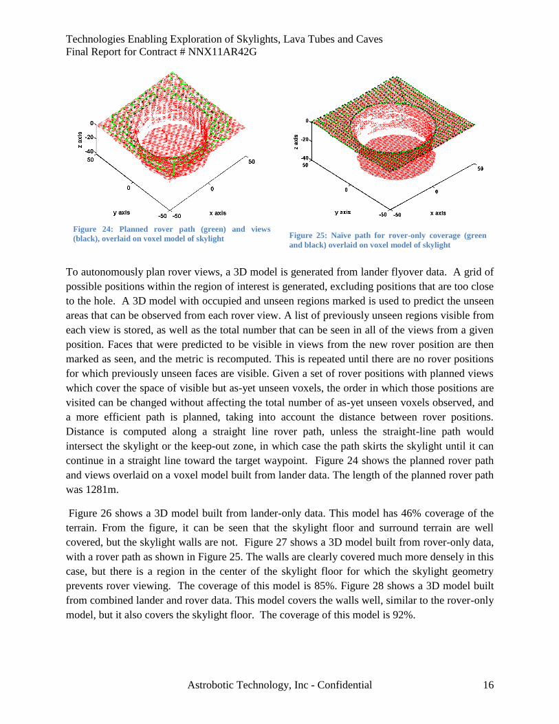
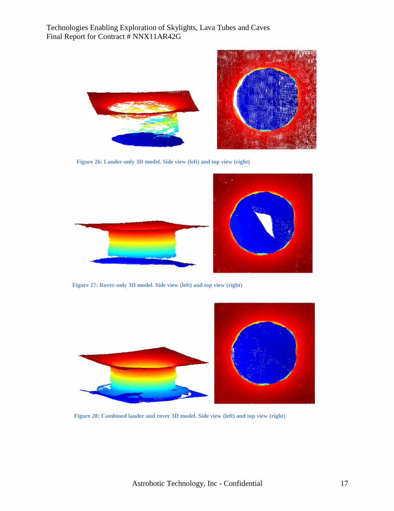
Figure 26 shows a 3D model built from lander-only data. This model has 46% coverage of the
terrain. From the figure, it can be seen that the skylight floor and surround terrain are well
covered, but the skylight walls are not. Figure 27 shows a 3D model built from rover-only data,
with a rover path as shown in Figure 25. The walls are clearly covered much more densely in this
case, but there is a region in the center of the skylight floor for which the skylight geometry
prevents rover viewing. The coverage of this model is 85%. Figure 28 shows a 3D model built
from combined lander and rover data. This model covers the walls well, similar to the rover-only
model, but it also covers the skylight floor. The coverage of this model is 92%.
Figure 25: Naïve path for rover-only coverage (green
and black) overlaid on voxel model of skylight
Figure 24: Planned rover path (green) and views
(black), overlaid on voxel model of skylight
Technologies Enabling Exploration of Skylights, Lava Tubes and Caves
Final Report for Contract # NNX11AR42G
Astrobotic Technology, Inc - Confidential 17
Figure 28: Combined lander and rover 3D model. Side view (left) and top view (right)
Figure 27: Rover-only 3D model. Side view (left) and top view (right)
Figure 26: Lander-only 3D model. Side view (left) and top view (right)
Technologies Enabling Exploration of Skylights, Lava Tubes and Caves
Final Report for Contract # NNX11AR42G
Astrobotic Technology, Inc - Confidential 18
3.2.2 Methods for Stitching Lander and Rover Models
The experiments in Section 3.2.1 were
conducted assuming perfect knowledge of
sensor positions and orientations, but for a
real mission, these will not be known
perfectly. Planetary destinations lack GPS
infrastructure for absolute localization, and
relative localization methods, such as
inertial navigation or wheel odometry,
produce estimates that drift over time. A
drifting position estimate can result in a
severely distorted model, unless something
is done to correct the model.
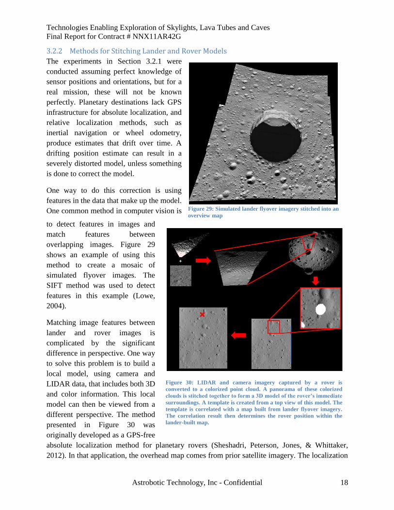
One way to do this correction is using
features in the data that make up the model.
One common method in computer vision is
to detect features in images and
match features between
overlapping images. Figure 29
shows an example of using this
method to create a mosaic of
simulated flyover images. The
SIFT method was used to detect
features in this example (Lowe,
2004).
Matching image features between
lander and rover images is
complicated by the significant
difference in perspective. One way
to solve this problem is to build a
local model, using camera and
LIDAR data, that includes both 3D
and color information. This local
model can then be viewed from a
different perspective. The method
presented in Figure 30 was
originally developed as a GPS-free
absolute localization method for planetary rovers (Sheshadri, Peterson, Jones, & Whittaker,
2012). In that application, the overhead map comes from prior satellite imagery. The localization
Figure 29: Simulated lander flyover imagery stitched into an
overview map
Figure 30: LIDAR and camera imagery captured by a rover is
converted to a colorized point cloud. A panorama of these colorized
clouds is stitched together to form a 3D model of the rover’s immediate
surroundings. A template is created from a top view of this model. The
template is correlated with a map built from lander flyover imagery.
The correlation result then determines the rover position within the
lander-built map.
Technologies Enabling Exploration of Skylights, Lava Tubes and Caves
Final Report for Contract # NNX11AR42G
Astrobotic Technology, Inc - Confidential 19
precision is dependent on the resolution of the overhead map, and with new high resolution
imagery of the moon4, estimates to within 2m are expected. The same method can also be used to
align rover data with lander models, an essential step for complementary flyover and surface
modeling, and due to the higher resolution of the lander imagery, the alignment would be more
precise in this case.
4 The Lunar Reconnaissance Orbiter provided 0.5m/pixel imagery from its nominal mapping
orbit, and it is now capturing 0.25m/pixel imagery from a lower altitude orbit (Robinson, et al.,
2010) (Riris, Cavanaugh, Sun, Liivia, Rodriguez, & Neuman, 2010).
Technologies Enabling Exploration of Skylights, Lava Tubes and Caves
Final Report for Contract # NNX11AR42G
Astrobotic Technology, Inc - Confidential 20
4 Robot Configuration and Operations
4.1 Configuration Selection This research innovated robot configuration and operations for cave exploration addressing the
following configuration challenges: access & in-cave mobility, power and communication
configuration, control and autonomy, and subsurface sensing. Subsurface sensing is addressed in
detail in Section 5; the other challenges are addressed in this section.
Phase I Investigation of Robot Configuration and Subsurface Operation
Robot trade studies. Investigation of power, communication, and autonomy technologies. Analysis of
mission requirements.
Phase I Insights
Hybrid driving/hopping robot can engage likely terrain types by choosing appropriate traverse mode.
A tethered power and communications node lowered into a skylight enables robots to recharge and
communicate data to ground control without requiring the mobility to return to the surface.
Wireless power and data transmission within line-of-sight of the tethered communications node eliminate
the need for exploration robots to physically reach it, which is critical in unpredictable environments
where the tether end may be located in a rubble pile or similarly difficult terrain.
Combination of active sensing (good for shadowed regions but lower resolution and range limited by
power) and cameras (higher resolution but unable to determine 3D scale) required to build sufficiently
detailed models for science and robot operations.
Commercial magneto-inductive communications system indicates an achievable data rate of 2412bps
through rock.
Magneto-inductive comm requires a large and heavy antenna. While it is a great technology for later use in
cave operations, it may not be feasible for the first, lightweight robotic explorers.
Skylight geometry challenges single-perspective modeling of cave entrances. Combining lander flyover
and rover exploration data to autonomously model skylights exploits unique perspectives of flyover and
rover, and is feasible even in communications-limited locations.
Indications for Phase II Study
Phase II will design and prototype “Cavehopper” hybrid driving/hopping robot and test in field
demonstration at the culmination of the program.
Develop robust sensor packaging for the highly mobile Cavehopper platform; adapt methods and
algorithms to this limited sensing capability; develop planning for model generation.
While Phase I investigation identified an available communications solution for data transmission, it
requires significant mass and does not approach the data rate necessary for teleoperation, especially since
operating in an unpredictable environment requires a high degree of situational awareness. Phase II study
will focus on planning for autonomous hop operations (Hop Ops), including development of a Cavehopper
simulation.
Adapt flyover/surface modeling to plan Cavehopper traverses using data from Livewire and from previous
Cavehopper hops.
Technologies Enabling Exploration of Skylights, Lava Tubes and Caves
Final Report for Contract # NNX11AR42G
Astrobotic Technology, Inc - Confidential 21
4.1.1 Access and In-Cave Mobility
While skylights provide entry into caves, they lead robots to vertical descents, traverses over
significant rubble, and unpredictable obstacles (e.g., rock piles from partial ceiling collapses). A
robot large enough to drive over any obstacle is unlikely to fit into narrow passages. It would
also be prohibitively expensive to launch due to mass and volume requirements. This challenge
necessitates innovative approaches to access and in-cave mobility.
4.1.2 Power and Communication Configuration
Specialized robotic technologies and morphologies are needed to address the unique power and
communication challenges presented by subsurface environments. To explore skylights and lava
tubes, these robots must overcome various difficulties, including:
Extended periods without access to solar power
Limited accessibility to communication
Operating exclusively in a dark environment
4.1.3 Autonomy and Control
Limited communication, unpredictable terrain, and dark subsurface environments necessitate
complex autonomy and control technologies. Tunnels, caves, and tubes block communication
requiring full autonomy. Underground topology is complex and three-dimensional requiring
planners that handle unseen branches and maximize information gain while considering power
utilization. Planners must enable autonomous operation to gather information, perform science
goals, and return to entry without getting lost or losing power.
4.2 Configuration Development and Trade Study A trade study was conducted to explore the mobility design space for robots to enter and operate
in subterranean environment accessed via a skylight. The design concepts considered in this
study are illustrated in Table 1.
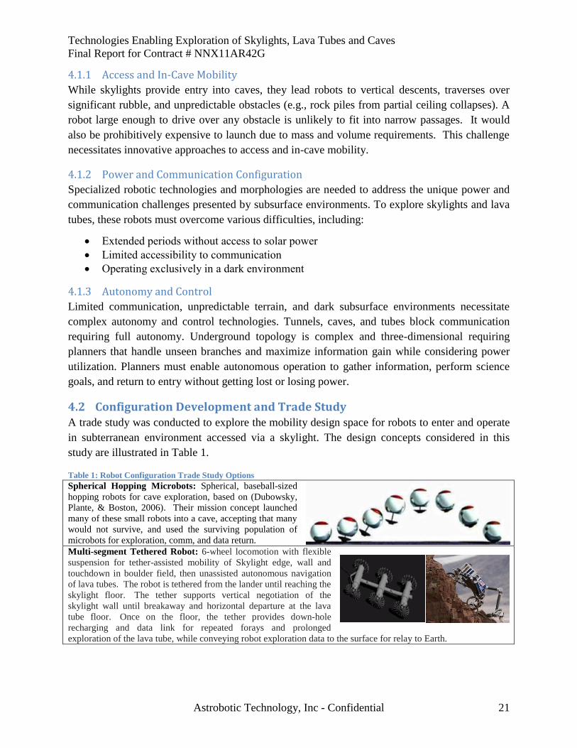
Table 1: Robot Configuration Trade Study Options
Spherical Hopping Microbots: Spherical, baseball-sized
hopping robots for cave exploration, based on (Dubowsky,
Plante, & Boston, 2006). Their mission concept launched
many of these small robots into a cave, accepting that many
would not survive, and used the surviving population of
microbots for exploration, comm, and data return.
Multi-segment Tethered Robot: 6-wheel locomotion with flexible
suspension for tether-assisted mobility of Skylight edge, wall and
touchdown in boulder field, then unassisted autonomous navigation
of lava tubes. The robot is tethered from the lander until reaching the
skylight floor. The tether supports vertical negotiation of the
skylight wall until breakaway and horizontal departure at the lava
tube floor. Once on the floor, the tether provides down-hole
recharging and data link for repeated forays and prolonged
exploration of the lava tube, while conveying robot exploration data to the surface for relay to Earth.
Technologies Enabling Exploration of Skylights, Lava Tubes and Caves
Final Report for Contract # NNX11AR42G
Astrobotic Technology, Inc - Confidential 22
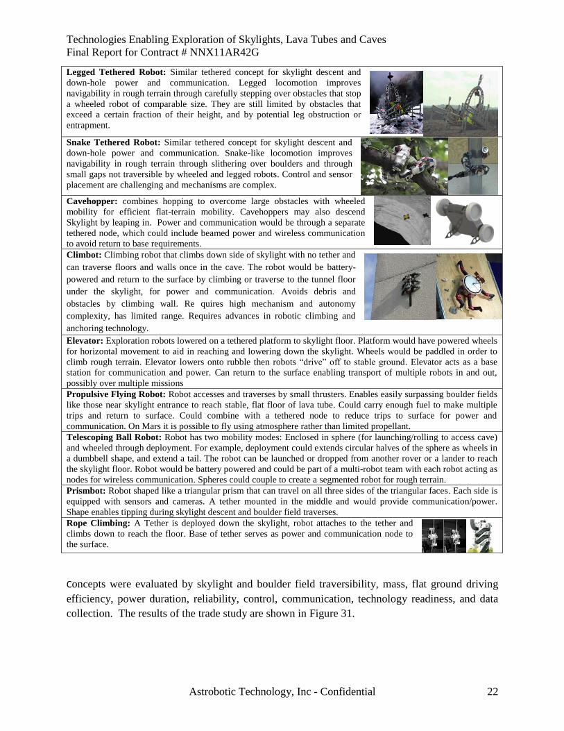
Legged Tethered Robot: Similar tethered concept for skylight descent and
down-hole power and communication. Legged locomotion improves
navigability in rough terrain through carefully stepping over obstacles that stop
a wheeled robot of comparable size. They are still limited by obstacles that
exceed a certain fraction of their height, and by potential leg obstruction or
entrapment.
Snake Tethered Robot: Similar tethered concept for skylight descent and
down-hole power and communication. Snake-like locomotion improves
navigability in rough terrain through slithering over boulders and through
small gaps not traversible by wheeled and legged robots. Control and sensor
placement are challenging and mechanisms are complex.
Cavehopper: combines hopping to overcome large obstacles with wheeled
mobility for efficient flat-terrain mobility. Cavehoppers may also descend
Skylight by leaping in. Power and communication would be through a separate
tethered node, which could include beamed power and wireless communication
to avoid return to base requirements. Climbot: Climbing robot that climbs down side of skylight with no tether and
can traverse floors and walls once in the cave. The robot would be battery-
powered and return to the surface by climbing or traverse to the tunnel floor
under the skylight, for power and communication. Avoids debris and
obstacles by climbing wall. Re quires high mechanism and autonomy
complexity, has limited range. Requires advances in robotic climbing and
anchoring technology.
Elevator: Exploration robots lowered on a tethered platform to skylight floor. Platform would have powered wheels
for horizontal movement to aid in reaching and lowering down the skylight. Wheels would be paddled in order to
climb rough terrain. Elevator lowers onto rubble then robots “drive” off to stable ground. Elevator acts as a base
station for communication and power. Can return to the surface enabling transport of multiple robots in and out,
possibly over multiple missions
Propulsive Flying Robot: Robot accesses and traverses by small thrusters. Enables easily surpassing boulder fields
like those near skylight entrance to reach stable, flat floor of lava tube. Could carry enough fuel to make multiple
trips and return to surface. Could combine with a tethered node to reduce trips to surface for power and
communication. On Mars it is possible to fly using atmosphere rather than limited propellant.
Telescoping Ball Robot: Robot has two mobility modes: Enclosed in sphere (for launching/rolling to access cave)
and wheeled through deployment. For example, deployment could extends circular halves of the sphere as wheels in
a dumbbell shape, and extend a tail. The robot can be launched or dropped from another rover or a lander to reach
the skylight floor. Robot would be battery powered and could be part of a multi-robot team with each robot acting as
nodes for wireless communication. Spheres could couple to create a segmented robot for rough terrain.
Prismbot: Robot shaped like a triangular prism that can travel on all three sides of the triangular faces. Each side is
equipped with sensors and cameras. A tether mounted in the middle and would provide communication/power.
Shape enables tipping during skylight descent and boulder field traverses.
Rope Climbing: A Tether is deployed down the skylight, robot attaches to the tether and
climbs down to reach the floor. Base of tether serves as power and communication node to
the surface.
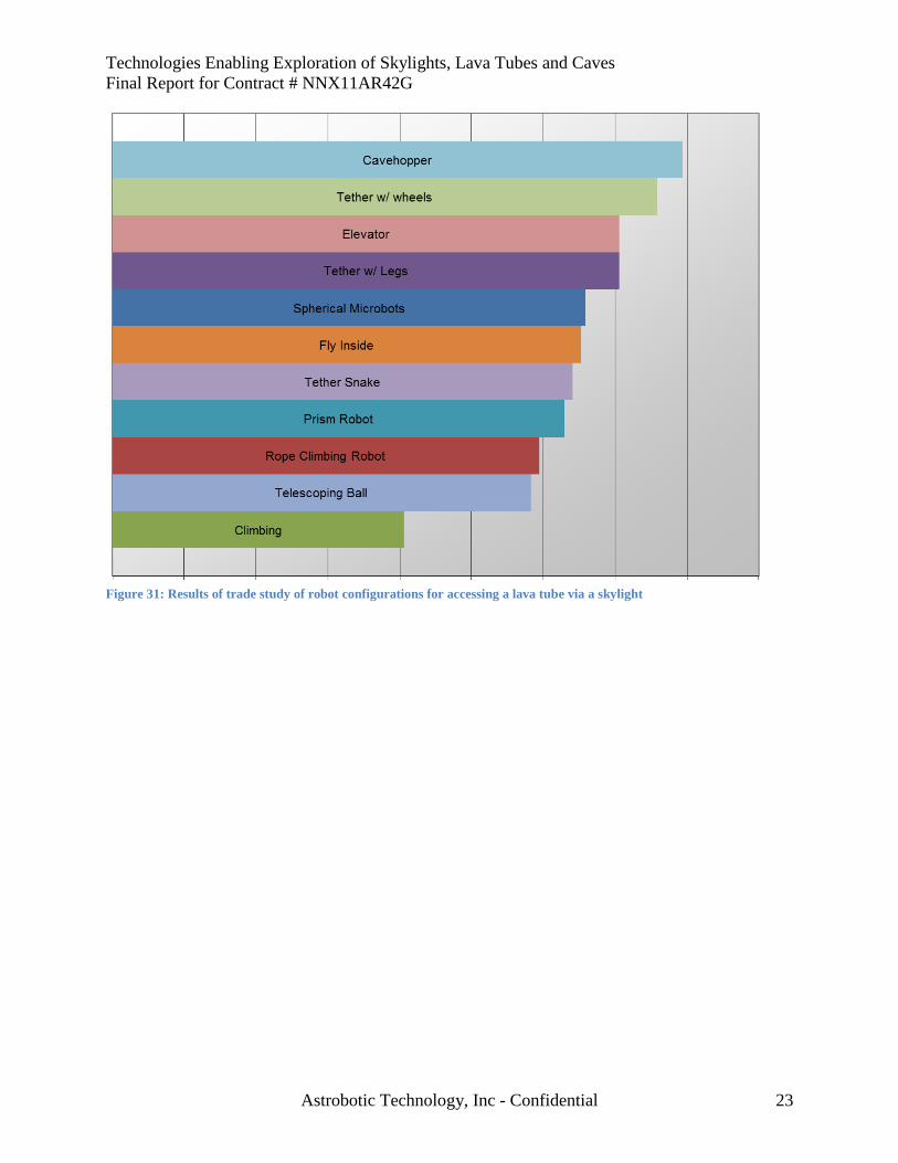
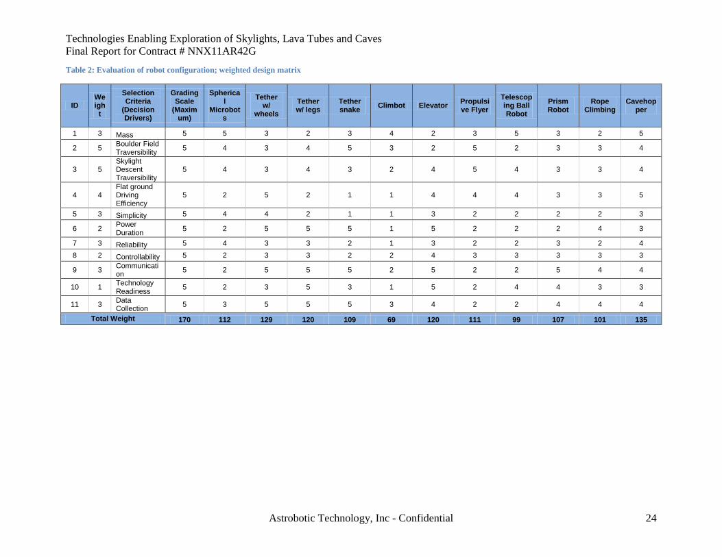
Concepts were evaluated by skylight and boulder field traversibility, mass, flat ground driving
efficiency, power duration, reliability, control, communication, technology readiness, and data
collection. The results of the trade study are shown in Figure 31.
Technologies Enabling Exploration of Skylights, Lava Tubes and Caves
Final Report for Contract # NNX11AR42G
Astrobotic Technology, Inc - Confidential 23
Figure 31: Results of trade study of robot configurations for accessing a lava tube via a skylight
Technologies Enabling Exploration of Skylights, Lava Tubes and Caves
Final Report for Contract # NNX11AR42G
Astrobotic Technology, Inc - Confidential 24
Table 2: Evaluation of robot configuration; weighted design matrix
ID Weigh
t
Selection Criteria
(Decision Drivers)
Grading Scale
(Maximum)
Spherical
Microbots
Tether w/
wheels
Tether w/ legs
Tether snake
Climbot Elevator Propulsive Flyer
Telescoping Ball Robot
Prism Robot
Rope Climbing
Cavehopper
1 3 Mass 5 5 3 2 3 4 2 3 5 3 2 5
2 5 Boulder Field Traversibility
5 4 3 4 5 3 2 5 2 3 3 4
3 5 Skylight Descent Traversibility
5 4 3 4 3 2 4 5 4 3 3 4
4 4 Flat ground Driving Efficiency
5 2 5 2 1 1 4 4 4 3 3 5
5 3 Simplicity 5 4 4 2 1 1 3 2 2 2 2 3
6 2 Power Duration
5 2 5 5 5 1 5 2 2 2 4 3
7 3 Reliability 5 4 3 3 2 1 3 2 2 3 2 4
8 2 Controllability 5 2 3 3 2 2 4 3 3 3 3 3
9 3 Communication
5 2 5 5 5 2 5 2 2 5 4 4
10 1 Technology Readiness
5 2 3 5 3 1 5 2 4 4 3 3
11 3 Data Collection
5 3 5 5 5 3 4 2 2 4 4 4
Total Weight 170 112 129 120 109 69 120 111 99 107 101 135
Technologies Enabling Exploration of Skylights, Lava Tubes and Caves
Final Report for Contract # NNX11AR42G
Astrobotic Technology, Inc - Confidential 25
4.3 Selected Configuration The configuration and exploration scenario resulting from design, analysis and trade study is the
Cavehopper with a separate tethered robot (Livewire) to supply power and communication. This
configuration was used as the basis to develop a detailed mission scenario and robot concepts.
This concept is explained in greater detail in Section 2 of this report.
4.3.1 Access and Mobility
Legged robots have been proposed for navigating rough terrain, carefully stepping over obstacles
that stop a wheeled robot of comparable size. They are still limited by obstacles that exceed a
certain fraction of their height, and by potential leg obstruction or entrapment. They also cannot
exploit the benefits of power-efficient wheeled motion on smooth terrain.
Hopping robots can be small and light, making them effective for tight spaces and economical to
launch. By hopping, especially in the lower gravity encountered on many planetary bodies
beyond Earth, they can overcome obstacles many
times their own size.
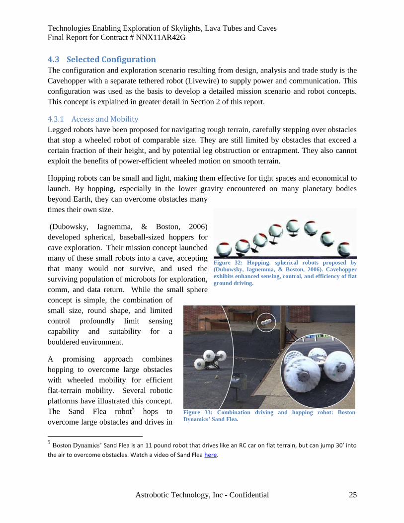
(Dubowsky, Iagnemma, & Boston, 2006)
developed spherical, baseball-sized hoppers for
cave exploration. Their mission concept launched
many of these small robots into a cave, accepting
that many would not survive, and used the
surviving population of microbots for exploration,
comm, and data return. While the small sphere
concept is simple, the combination of
small size, round shape, and limited
control profoundly limit sensing
capability and suitability for a
bouldered environment.
A promising approach combines
hopping to overcome large obstacles
with wheeled mobility for efficient
flat-terrain mobility. Several robotic
platforms have illustrated this concept.
The Sand Flea robot5 hops to
overcome large obstacles and drives in
5 Boston Dynamics’ Sand Flea is an 11 pound robot that drives like an RC car on flat terrain, but can jump 30’ into
the air to overcome obstacles. Watch a video of Sand Flea here.
Figure 32: Hopping, spherical robots proposed by
(Dubowsky, Iagnemma, & Boston, 2006). Cavehopper
exhibits enhanced sensing, control, and efficiency of flat
ground driving.
Figure 33: Combination driving and hopping robot: Boston
Dynamics’ Sand Flea.
Technologies Enabling Exploration of Skylights, Lava Tubes and Caves
Final Report for Contract # NNX11AR42G
Astrobotic Technology, Inc - Confidential 26
areas with more benign terrain. This approach is ideal for lava tube caves, where there are large
expanses of relatively flat floor between piles of rubble from ceiling collapse. The Sand Flea
platform has demonstrated hopping 8m in the air on Earth to leap buildings and cliffs from a start
on flat ground.
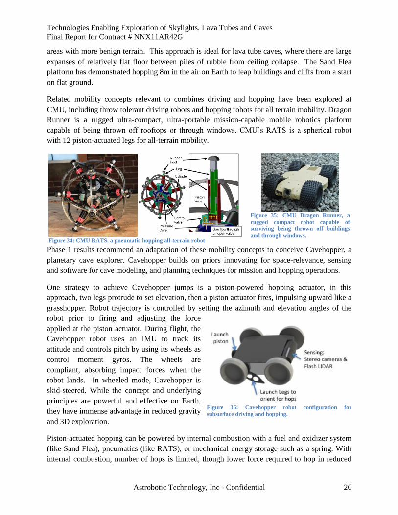
Related mobility concepts relevant to combines driving and hopping have been explored at
CMU, including throw tolerant driving robots and hopping robots for all terrain mobility. Dragon
Runner is a rugged ultra-compact, ultra-portable mission-capable mobile robotics platform
capable of being thrown off rooftops or through windows. CMU’s RATS is a spherical robot
with 12 piston-actuated legs for all-terrain mobility.
Phase 1 results recommend an adaptation of these mobility concepts to conceive Cavehopper, a
planetary cave explorer. Cavehopper builds on priors innovating for space-relevance, sensing
and software for cave modeling, and planning techniques for mission and hopping operations.
One strategy to achieve Cavehopper jumps is a piston-powered hopping actuator, in this
approach, two legs protrude to set elevation, then a piston actuator fires, impulsing upward like a
grasshopper. Robot trajectory is controlled by setting the azimuth and elevation angles of the
robot prior to firing and adjusting the force
applied at the piston actuator. During flight, the
Cavehopper robot uses an IMU to track its
attitude and controls pitch by using its wheels as
control moment gyros. The wheels are
compliant, absorbing impact forces when the
robot lands. In wheeled mode, Cavehopper is
skid-steered. While the concept and underlying
principles are powerful and effective on Earth,
they have immense advantage in reduced gravity
and 3D exploration.
Piston-actuated hopping can be powered by internal combustion with a fuel and oxidizer system
(like Sand Flea), pneumatics (like RATS), or mechanical energy storage such as a spring. With
internal combustion, number of hops is limited, though lower force required to hop in reduced
Figure 35: CMU Dragon Runner, a
rugged compact robot capable of
surviving being thrown off buildings
and through windows. Figure 34: CMU RATS, a pneumatic hopping all-terrain robot
Figure 36: Cavehopper robot configuration for
subsurface driving and hopping.
Technologies Enabling Exploration of Skylights, Lava Tubes and Caves
Final Report for Contract # NNX11AR42G
Astrobotic Technology, Inc - Confidential 27
gravity on planetary bodies such as the Moon or Mars, coupled with technology development to
improve the energy density of the fuel system, could significantly increase hop yield.
Alternatively, the piston could be powered by a mechanical spring compressed by an electric
actuator that, while less efficient, removes the hop limit inherent in a bipropellant system. On
planetary bodies with an atmosphere, pneumatic actuation or compressed air could provide
rechargeable hopping.
An additional approach to achieve “hopping” is a propulsive approach to fly over hazards that
cannot be surpassed by driving. This approach is limited by fuel, but has the advantage of higher
controllability of flight trajectories.
4.3.2 Power and Communication Configuration
Power is addressed through the “Livewire” robot. Livewire makes a tethered descent into a
Skylight. Livewire tether creates a connection to the lander’s communication and power on the
surface. Livewire beams power and wirelessly communicates with Cavehoppers from a high
vantage point hanging in the Skylight rather than touching down to the floor. In addition,
cameras on-board Livewire could provide reconnaissance and track Cavehopper robots for
improved localization. The Cavehoppers explore and return to within line-of-sight of the
Livewire to relay their data and recharge from beamed power. Livewire transmits the
Cavehoppers’ data up the tether to an antenna on the lander, which transmits to a relay satellite
or directly to Earth. This foray-”phone home” cycle is repeated until all lava tube regions within
battery range of the skylight have been explored.
Phase 1 Identified five key enabling power and communication technologies relevant to
planetary subsurface exploration robots:
High energy density batteries enable longer cave excursions with low battery masses.
Power beaming enables recharging of Cavehopper robots from a solar powered lander. Power
beaming is under development by several groups including LaserMotive, who won the NASA
Power Beaming Challenge and are presently working for NASA to design the architecture to use
lasers to launch rockets and power satellites, and, eventually, power lunar bases (LaserMotive,
2012).
Technologies Enabling Exploration of Skylights, Lava Tubes and Caves
Final Report for Contract # NNX11AR42G
Astrobotic Technology, Inc - Confidential 28
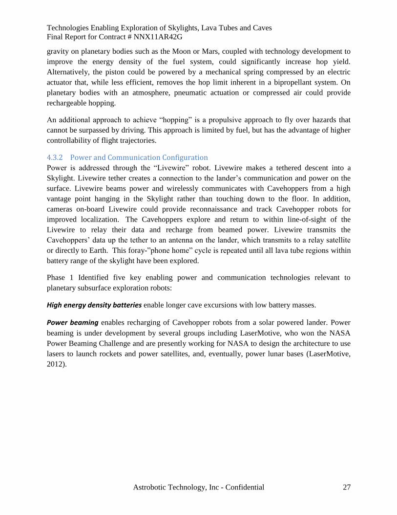
Figure 37: Cross section of possible tether design, showing key
elements
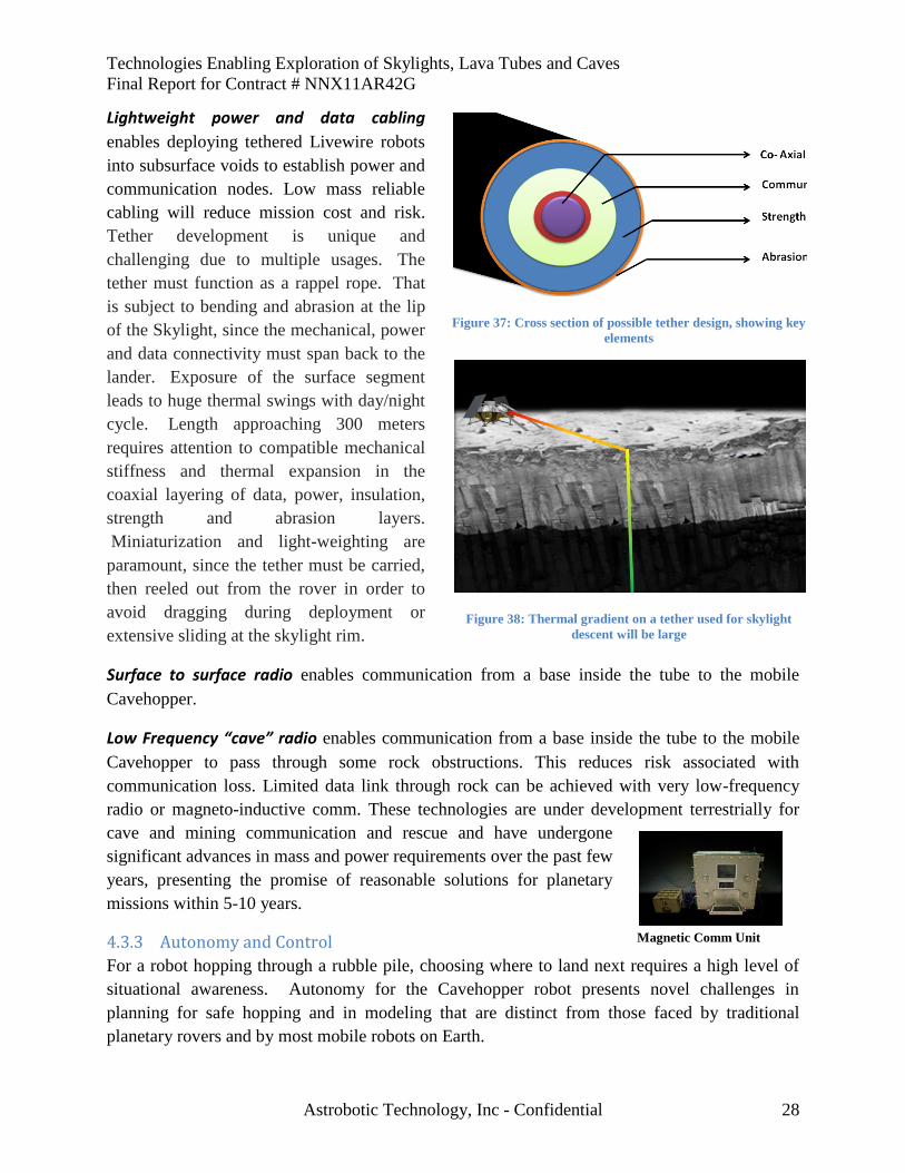
Figure 38: Thermal gradient on a tether used for skylight
descent will be large
Lightweight power and data cabling
enables deploying tethered Livewire robots
into subsurface voids to establish power and
communication nodes. Low mass reliable
cabling will reduce mission cost and risk.
Tether development is unique and
challenging due to multiple usages. The
tether must function as a rappel rope. That
is subject to bending and abrasion at the lip
of the Skylight, since the mechanical, power
and data connectivity must span back to the
lander. Exposure of the surface segment
leads to huge thermal swings with day/night
cycle. Length approaching 300 meters
requires attention to compatible mechanical
stiffness and thermal expansion in the
coaxial layering of data, power, insulation,
strength and abrasion layers.
Miniaturization and light-weighting are
paramount, since the tether must be carried,
then reeled out from the rover in order to
avoid dragging during deployment or
extensive sliding at the skylight rim.
Surface to surface radio enables communication from a base inside the tube to the mobile
Cavehopper.
Low Frequency “cave” radio enables communication from a base inside the tube to the mobile
Cavehopper to pass through some rock obstructions. This reduces risk associated with
communication loss. Limited data link through rock can be achieved with very low-frequency
radio or magneto-inductive comm. These technologies are under development terrestrially for
cave and mining communication and rescue and have undergone
significant advances in mass and power requirements over the past few
years, presenting the promise of reasonable solutions for planetary
missions within 5-10 years.
4.3.3 Autonomy and Control
For a robot hopping through a rubble pile, choosing where to land next requires a high level of
situational awareness. Autonomy for the Cavehopper robot presents novel challenges in
planning for safe hopping and in modeling that are distinct from those faced by traditional
planetary rovers and by most mobile robots on Earth.
Magnetic Comm Unit
Technologies Enabling Exploration of Skylights, Lava Tubes and Caves
Final Report for Contract # NNX11AR42G
Astrobotic Technology, Inc - Confidential 29
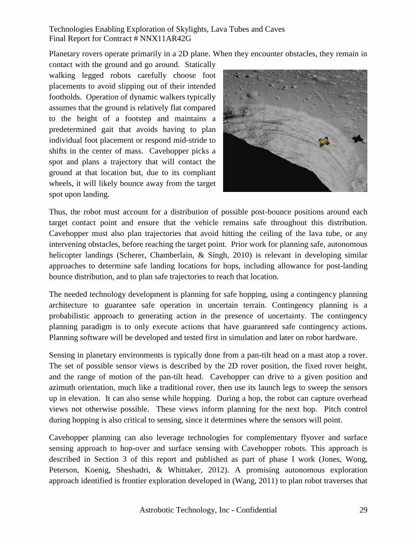
Planetary rovers operate primarily in a 2D plane. When they encounter obstacles, they remain in
contact with the ground and go around. Statically
walking legged robots carefully choose foot
placements to avoid slipping out of their intended
footholds. Operation of dynamic walkers typically
assumes that the ground is relatively flat compared
to the height of a footstep and maintains a
predetermined gait that avoids having to plan
individual foot placement or respond mid-stride to
shifts in the center of mass. Cavehopper picks a
spot and plans a trajectory that will contact the
ground at that location but, due to its compliant
wheels, it will likely bounce away from the target
spot upon landing.
Thus, the robot must account for a distribution of possible post-bounce positions around each
target contact point and ensure that the vehicle remains safe throughout this distribution.
Cavehopper must also plan trajectories that avoid hitting the ceiling of the lava tube, or any
intervening obstacles, before reaching the target point. Prior work for planning safe, autonomous
helicopter landings (Scherer, Chamberlain, & Singh, 2010) is relevant in developing similar
approaches to determine safe landing locations for hops, including allowance for post-landing
bounce distribution, and to plan safe trajectories to reach that location.
The needed technology development is planning for safe hopping, using a contingency planning
architecture to guarantee safe operation in uncertain terrain. Contingency planning is a
probabilistic approach to generating action in the presence of uncertainty. The contingency
planning paradigm is to only execute actions that have guaranteed safe contingency actions.
Planning software will be developed and tested first in simulation and later on robot hardware.
Sensing in planetary environments is typically done from a pan-tilt head on a mast atop a rover.
The set of possible sensor views is described by the 2D rover position, the fixed rover height,
and the range of motion of the pan-tilt head. Cavehopper can drive to a given position and
azimuth orientation, much like a traditional rover, then use its launch legs to sweep the sensors
up in elevation. It can also sense while hopping. During a hop, the robot can capture overhead
views not otherwise possible. These views inform planning for the next hop. Pitch control
during hopping is also critical to sensing, since it determines where the sensors will point.
Cavehopper planning can also leverage technologies for complementary flyover and surface
sensing approach to hop-over and surface sensing with Cavehopper robots. This approach is
described in Section 3 of this report and published as part of phase I work (Jones, Wong,
Peterson, Koenig, Sheshadri, & Whittaker, 2012). A promising autonomous exploration
approach identified is frontier exploration developed in (Wang, 2011) to plan robot traverses that
Technologies Enabling Exploration of Skylights, Lava Tubes and Caves
Final Report for Contract # NNX11AR42G
Astrobotic Technology, Inc - Confidential 30
enable sensing of unexplored areas. Control also addresses low-level planning for sensing while
the robot is on the ground and during hops. Next steps include developing an approach that given
a hop planned to get the robot to a target destination determines how the pitch should be
controlled along the trajectory to capture the desired data.
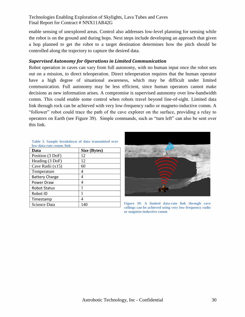
Supervised Autonomy for Operations in Limited Communication
Robot operation in caves can vary from full autonomy, with no human input once the robot sets
out on a mission, to direct teleoperation. Direct teleoperation requires that the human operator
have a high degree of situational awareness, which may be difficult under limited
communication. Full autonomy may be less efficient, since human operators cannot make
decisions as new information arises. A compromise is supervised autonomy over low-bandwidth
comm. This could enable some control when robots travel beyond line-of-sight. Limited data
link through rock can be achieved with very low-frequency radio or magneto-inductive comm. A
“follower” robot could trace the path of the cave explorer on the surface, providing a relay to
operators on Earth (see Figure 39). Simple commands, such as “turn left” can also be sent over
this link.
Figure 39: A limited data-rate link through cave
ceilings can be achieved using very low-frequency radio
or magneto-inductive comm
Table 3. Sample breakdown of data transmitted over
low-data-rate comm. link
Data Size (Bytes)
Position (3 DoF) 12
Heading (3 DoF) 12
Cave Radii (x15) 60
Temperature 4
Battery Charge 4
Power Draw 4
Robot Status 1
Robot ID 1
Timestamp 4
Science Data 140
Technologies Enabling Exploration of Skylights, Lava Tubes and Caves
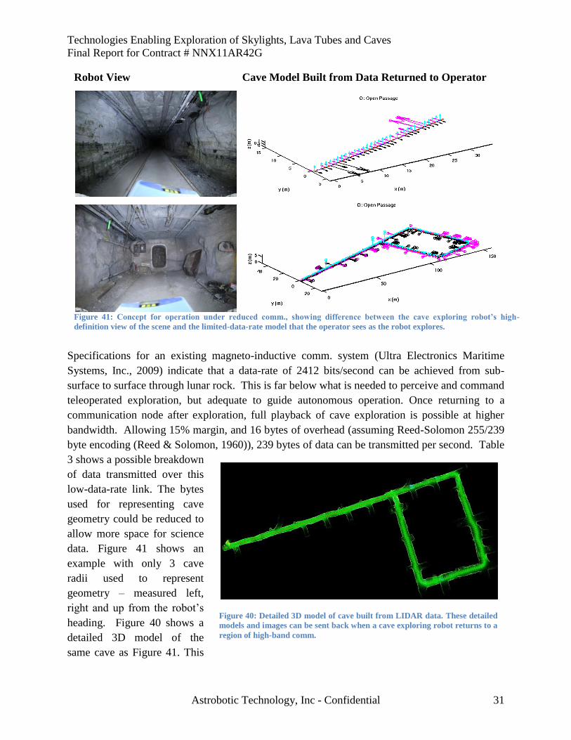
Final Report for Contract # NNX11AR42G
Astrobotic Technology, Inc - Confidential 31
Specifications for an existing magneto-inductive comm. system (Ultra Electronics Maritime
Systems, Inc., 2009) indicate that a data-rate of 2412 bits/second can be achieved from sub-
surface to surface through lunar rock. This is far below what is needed to perceive and command
teleoperated exploration, but adequate to guide autonomous operation. Once returning to a
communication node after exploration, full playback of cave exploration is possible at higher
bandwidth. Allowing 15% margin, and 16 bytes of overhead (assuming Reed-Solomon 255/239
byte encoding (Reed & Solomon, 1960)), 239 bytes of data can be transmitted per second. Table
3 shows a possible breakdown
of data transmitted over this
low-data-rate link. The bytes
used for representing cave
geometry could be reduced to
allow more space for science
data. Figure 41 shows an
example with only 3 cave
radii used to represent
geometry – measured left,
right and up from the robot’s
heading. Figure 40 shows a
detailed 3D model of the
same cave as Figure 41. This
Robot View Cave Model Built from Data Returned to Operator
Figure 41: Concept for operation under reduced comm., showing difference between the cave exploring robot’s high-
definition view of the scene and the limited-data-rate model that the operator sees as the robot explores.
Figure 40: Detailed 3D model of cave built from LIDAR data. These detailed
models and images can be sent back when a cave exploring robot returns to a
region of high-band comm.
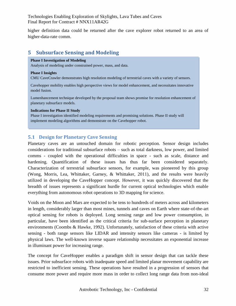
Technologies Enabling Exploration of Skylights, Lava Tubes and Caves
Final Report for Contract # NNX11AR42G
Astrobotic Technology, Inc - Confidential 32
higher definition data could be returned after the cave explorer robot returned to an area of
higher-data-rate comm.
5 Subsurface Sensing and Modeling
5.1 Design for Planetary Cave Sensing Planetary caves are an untouched domain for robotic perception. Sensor design includes
considerations for traditional subsurface robots – such as total darkness, low power, and limited
comms - coupled with the operational difficulties in space - such as scale, distance and
hardening. Quantification of these issues has thus far been considered separately.
Characterization of terrestrial subsurface sensors, for example, was pioneered by this group
(Wong, Morris, Lea, Whittaker, Garney, & Whittaker, 2011), and the results were heavily
utilized in developing the CaveHopper concept. However, it was quickly discovered that the
breadth of issues represents a significant hurdle for current optical technologies which enable
everything from autonomous robot operations to 3D mapping for science.
Voids on the Moon and Mars are expected to be tens to hundreds of meters across and kilometers
in length, considerably larger than most mines, tunnels and caves on Earth where state-of-the-art
optical sensing for robots is deployed. Long sensing range and low power consumption, in
particular, have been identified as the critical criteria for sub-surface perception in planetary
environments (Coombs & Hawke, 1992). Unfortunately, satisfaction of these criteria with active
sensing - both range sensors like LIDAR and intensity sensors like cameras - is limited by
physical laws. The well-known inverse square relationship necessitates an exponential increase
in illuminant power for increasing range.
The concept for CaveHopper enables a paradigm shift in sensor design that can tackle these
issues. Prior subsurface robots with inadequate speed and limited planar movement capability are
restricted to inefficient sensing. These operations have resulted in a progression of sensors that
consume more power and require more mass in order to collect long range data from non-ideal
Phase I Investigation of Modeling
Analysis of modeling under constrained power, mass, and data.
Phase I Insights
CMU CaveCrawler demonstrates high resolution modeling of terrestrial caves with a variety of sensors.
Cavehopper mobility enables high perspective views for model enhancement, and necessitates innovative
model fusion.
Lumenhancement technique developed by the proposal team shows promise for resolution enhancement of
planetary subsurface models.
Indications for Phase II Study
Phase I investigation identified modeling requirements and promising solutions. Phase II study will
implement modeling algorithms and demonstrate on the Cavehopper robot.
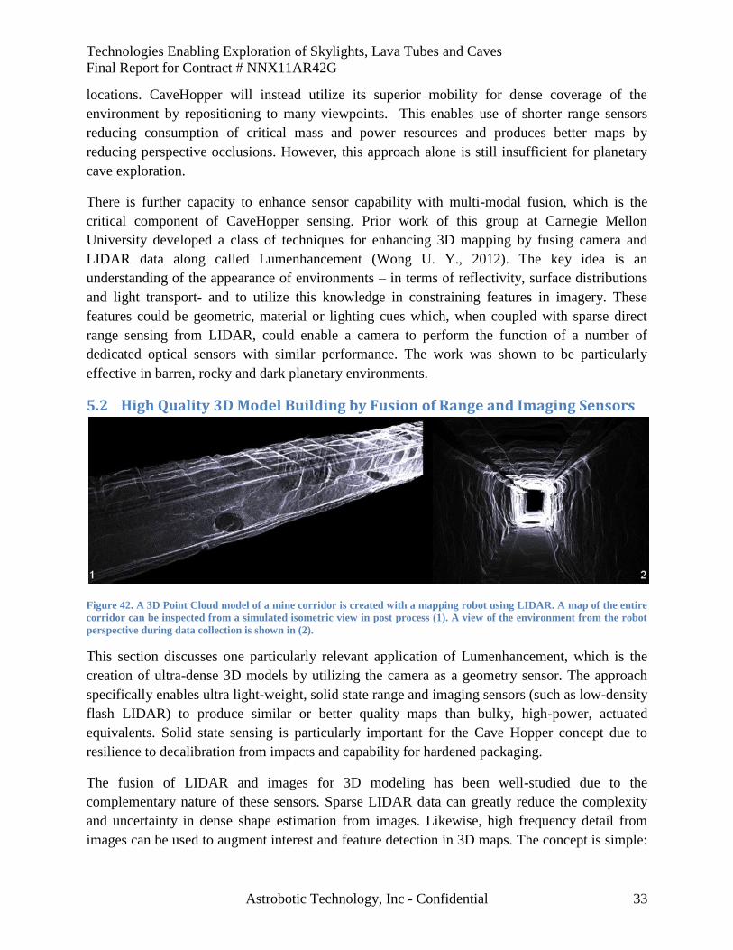
Technologies Enabling Exploration of Skylights, Lava Tubes and Caves
Final Report for Contract # NNX11AR42G
Astrobotic Technology, Inc - Confidential 33
locations. CaveHopper will instead utilize its superior mobility for dense coverage of the
environment by repositioning to many viewpoints. This enables use of shorter range sensors
reducing consumption of critical mass and power resources and produces better maps by
reducing perspective occlusions. However, this approach alone is still insufficient for planetary
cave exploration.
There is further capacity to enhance sensor capability with multi-modal fusion, which is the
critical component of CaveHopper sensing. Prior work of this group at Carnegie Mellon
University developed a class of techniques for enhancing 3D mapping by fusing camera and
LIDAR data along called Lumenhancement (Wong U. Y., 2012). The key idea is an
understanding of the appearance of environments – in terms of reflectivity, surface distributions
and light transport- and to utilize this knowledge in constraining features in imagery. These
features could be geometric, material or lighting cues which, when coupled with sparse direct
range sensing from LIDAR, could enable a camera to perform the function of a number of
dedicated optical sensors with similar performance. The work was shown to be particularly
effective in barren, rocky and dark planetary environments.
5.2 High Quality 3D Model Building by Fusion of Range and Imaging Sensors
Figure 42. A 3D Point Cloud model of a mine corridor is created with a mapping robot using LIDAR. A map of the entire
corridor can be inspected from a simulated isometric view in post process (1). A view of the environment from the robot
perspective during data collection is shown in (2).
This section discusses one particularly relevant application of Lumenhancement, which is the
creation of ultra-dense 3D models by utilizing the camera as a geometry sensor. The approach
specifically enables ultra light-weight, solid state range and imaging sensors (such as low-density
flash LIDAR) to produce similar or better quality maps than bulky, high-power, actuated
equivalents. Solid state sensing is particularly important for the Cave Hopper concept due to
resilience to decalibration from impacts and capability for hardened packaging.
The fusion of LIDAR and images for 3D modeling has been well-studied due to the
complementary nature of these sensors. Sparse LIDAR data can greatly reduce the complexity
and uncertainty in dense shape estimation from images. Likewise, high frequency detail from
images can be used to augment interest and feature detection in 3D maps. The concept is simple:
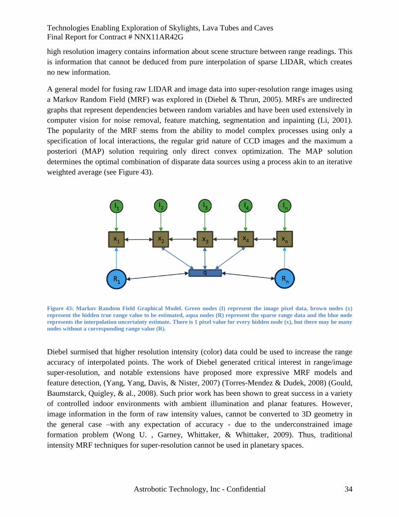
Technologies Enabling Exploration of Skylights, Lava Tubes and Caves
Final Report for Contract # NNX11AR42G
Astrobotic Technology, Inc - Confidential 34
high resolution imagery contains information about scene structure between range readings. This
is information that cannot be deduced from pure interpolation of sparse LIDAR, which creates
no new information.
A general model for fusing raw LIDAR and image data into super-resolution range images using
a Markov Random Field (MRF) was explored in (Diebel & Thrun, 2005). MRFs are undirected
graphs that represent dependencies between random variables and have been used extensively in
computer vision for noise removal, feature matching, segmentation and inpainting (Li, 2001).
The popularity of the MRF stems from the ability to model complex processes using only a
specification of local interactions, the regular grid nature of CCD images and the maximum a
posteriori (MAP) solution requiring only direct convex optimization. The MAP solution
determines the optimal combination of disparate data sources using a process akin to an iterative
weighted average (see Figure 43).
Figure 43: Markov Random Field Graphical Model. Green nodes (I) represent the image pixel data, brown nodes (x)
represent the hidden true range value to be estimated, aqua nodes (R) represent the sparse range data and the blue node
represents the interpolation uncertainty estimate. There is 1 pixel value for every hidden node (x), but there may be many
nodes without a corresponding range value (R).
Diebel surmised that higher resolution intensity (color) data could be used to increase the range
accuracy of interpolated points. The work of Diebel generated critical interest in range/image
super-resolution, and notable extensions have proposed more expressive MRF models and
feature detection, (Yang, Yang, Davis, & Nister, 2007) (Torres-Mendez & Dudek, 2008) (Gould,
Baumstarck, Quigley, & al., 2008). Such prior work has been shown to great success in a variety
of controlled indoor environments with ambient illumination and planar features. However,
image information in the form of raw intensity values, cannot be converted to 3D geometry in
the general case –with any expectation of accuracy - due to the underconstrained image
formation problem (Wong U. , Garney, Whittaker, & Whittaker, 2009). Thus, traditional
intensity MRF techniques for super-resolution cannot be used in planetary spaces.
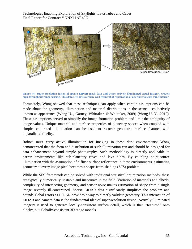
Technologies Enabling Exploration of Skylights, Lava Tubes and Caves
Final Report for Contract # NNX11AR42G
Astrobotic Technology, Inc - Confidential 35
Figure 44: Super-resolution fusion of sparse LIDAR mesh data and dense actively-illuminated visual imagery creates
high-throughput range sensing. This data set shows a rocky wall from robot exploration of a terrestrial coal mine interior.
Fortunately, Wong showed that these techniques can apply when certain assumptions can be
made about the geometry, illumination and material distributions in the scene – collectively
known as appearance (Wong U. , Garney, Whittaker, & Whittaker, 2009) (Wong U. Y., 2012).
These assumptions served to simplify the image formation problem and limit the ambiguity of
image values. Unique material and surface properties of planetary spaces when coupled with
simple, calibrated illumination can be used to recover geometric surface features with
unparalleled fidelity.
Robots must carry active illumination for imaging in these dark environments; Wong
demonstrated that the form and distribution of such illumination can and should be designed for
data enhancement beyond simple photography. Such methodology is directly applicable to
barren environments like sub-planetary caves and lava tubes. By coupling point-source
illumination with the assumption of diffuse surface reflectance in these environments, estimating
geometry at every image pixel becomes a shape-from-shading (SFS) problem.
While the SFS framework can be solved with traditional statistical optimization methods, these
are typically numerically unstable and inaccurate in the field. Variation of materials and albedo,
complexity of intersecting geometry, and sensor noise makes estimation of shape from a single
image severely ill-constrained. Sparse LIDAR data significantly simplifies the problem and
bounds global errors as LIDAR provides a way to directly validate geometry. This interaction of
LIDAR and camera data is the fundamental idea of super-resolution fusion. Actively illuminated
imagery is used to generate locally-consistent surface detail, which is then “textured” onto
blocky, but globally-consistent 3D range models.
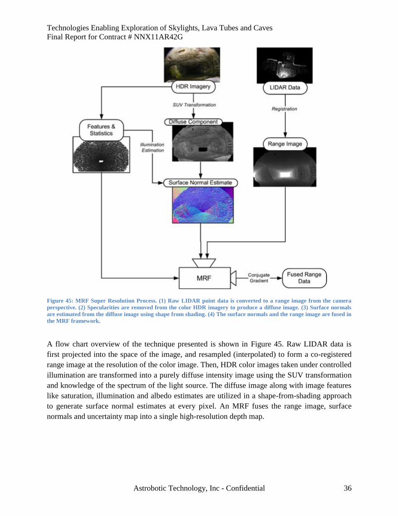
Technologies Enabling Exploration of Skylights, Lava Tubes and Caves
Final Report for Contract # NNX11AR42G
Astrobotic Technology, Inc - Confidential 36
Figure 45: MRF Super Resolution Process. (1) Raw LIDAR point data is converted to a range image from the camera
perspective. (2) Specularities are removed from the color HDR imagery to produce a diffuse image. (3) Surface normals
are estimated from the diffuse image using shape from shading. (4) The surface normals and the range image are fused in
the MRF framework.
A flow chart overview of the technique presented is shown in Figure 45. Raw LIDAR data is
first projected into the space of the image, and resampled (interpolated) to form a co-registered
range image at the resolution of the color image. Then, HDR color images taken under controlled
illumination are transformed into a purely diffuse intensity image using the SUV transformation
and knowledge of the spectrum of the light source. The diffuse image along with image features
like saturation, illumination and albedo estimates are utilized in a shape-from-shading approach
to generate surface normal estimates at every pixel. An MRF fuses the range image, surface
normals and uncertainty map into a single high-resolution depth map.
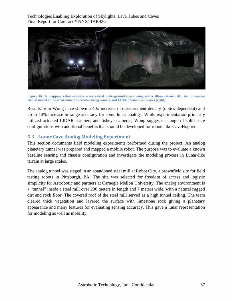
Technologies Enabling Exploration of Skylights, Lava Tubes and Caves
Final Report for Contract # NNX11AR42G
Astrobotic Technology, Inc - Confidential 37
Figure 46: A mapping robot explores a terrestrial underground space using active illumination (left). An immersive
virtual model of the environment is created using camera and LIDAR fusion techniques (right).
Results from Wong have shown a 40x increase in measurement density (optics dependent) and
up to 40% increase in range accuracy for some lunar analogs. While experimentation primarily
utilized actuated LIDAR scanners and fisheye cameras, Wong suggests a range of solid state
configurations with additional benefits that should be developed for robots like CaveHopper.
5.3 Lunar Cave Analog Modeling Experiment This section documents field modeling experiments performed during the project. An analog
planetary tunnel was prepared and mapped a mobile robot. The purpose was to evaluate a known
baseline sensing and chassis configuration and investigate the modeling process in Lunar-like
terrain at large scales.
The analog tunnel was staged in an abandoned steel mill at Robot City, a brownfield site for field
testing robots in Pittsburgh, PA. The site was selected for freedom of access and logistic
simplicity for Astrobotic and partners at Carnegie Mellon University. The analog environment is
a “tunnel” inside a steel mill over 200 meters in length and 7 meters wide, with a natural rugged
dirt and rock floor. The covered roof of the steel mill served as a high tunnel ceiling. The team
cleared thick vegetation and layered the surface with limestone rock giving a planetary
appearance and many features for evaluating sensing accuracy. This gave a lunar representation
for modeling as well as mobility.
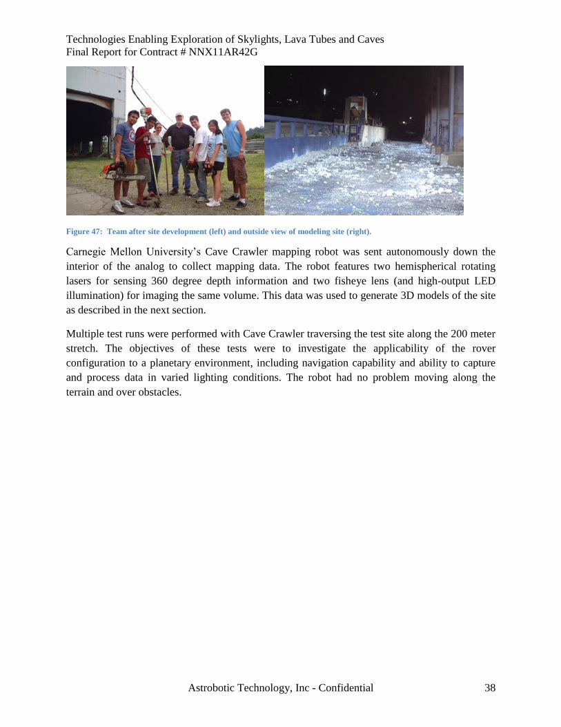
Technologies Enabling Exploration of Skylights, Lava Tubes and Caves
Final Report for Contract # NNX11AR42G
Astrobotic Technology, Inc - Confidential 38
Figure 47: Team after site development (left) and outside view of modeling site (right).
Carnegie Mellon University’s Cave Crawler mapping robot was sent autonomously down the
interior of the analog to collect mapping data. The robot features two hemispherical rotating
lasers for sensing 360 degree depth information and two fisheye lens (and high-output LED
illumination) for imaging the same volume. This data was used to generate 3D models of the site
as described in the next section.
Multiple test runs were performed with Cave Crawler traversing the test site along the 200 meter
stretch. The objectives of these tests were to investigate the applicability of the rover
configuration to a planetary environment, including navigation capability and ability to capture
and process data in varied lighting conditions. The robot had no problem moving along the
terrain and over obstacles.
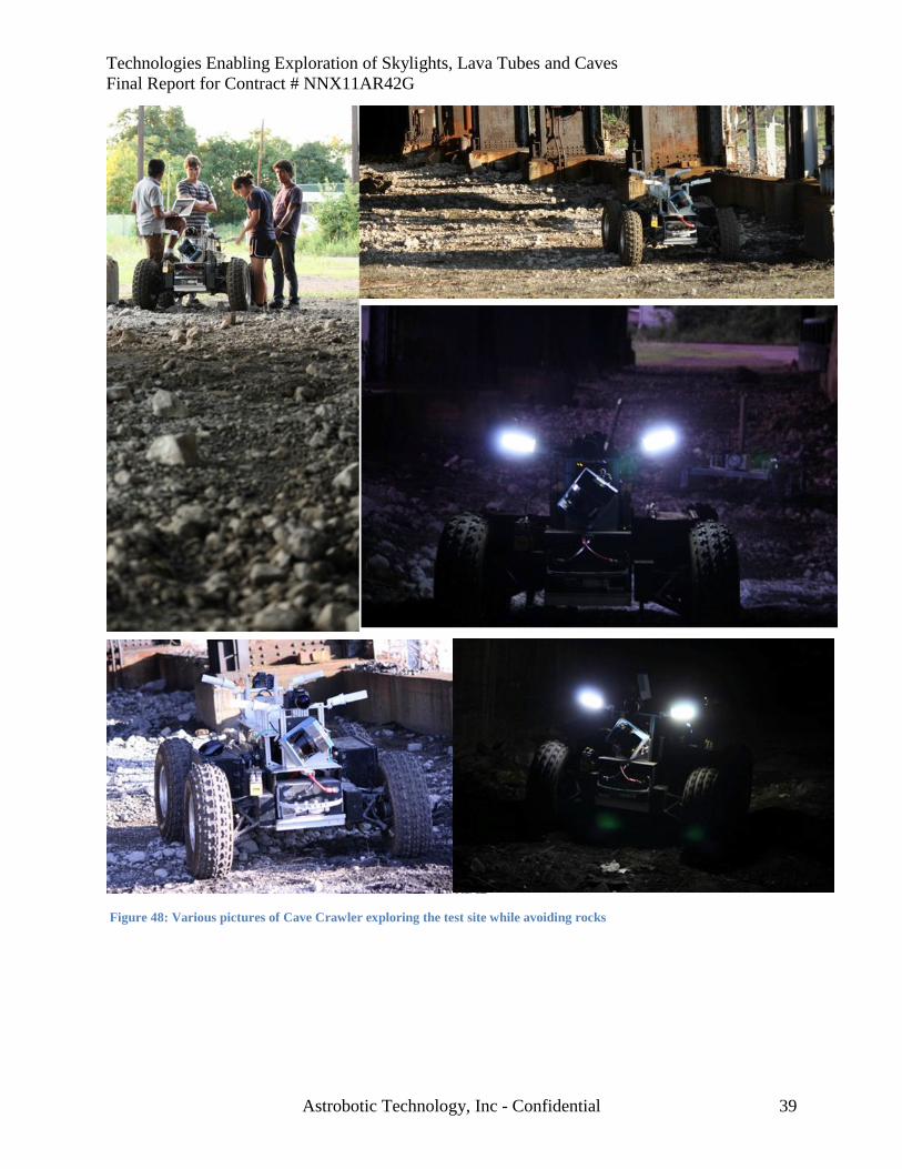
Technologies Enabling Exploration of Skylights, Lava Tubes and Caves
Final Report for Contract # NNX11AR42G
Astrobotic Technology, Inc - Confidential 39
Figure 48: Various pictures of Cave Crawler exploring the test site while avoiding rocks
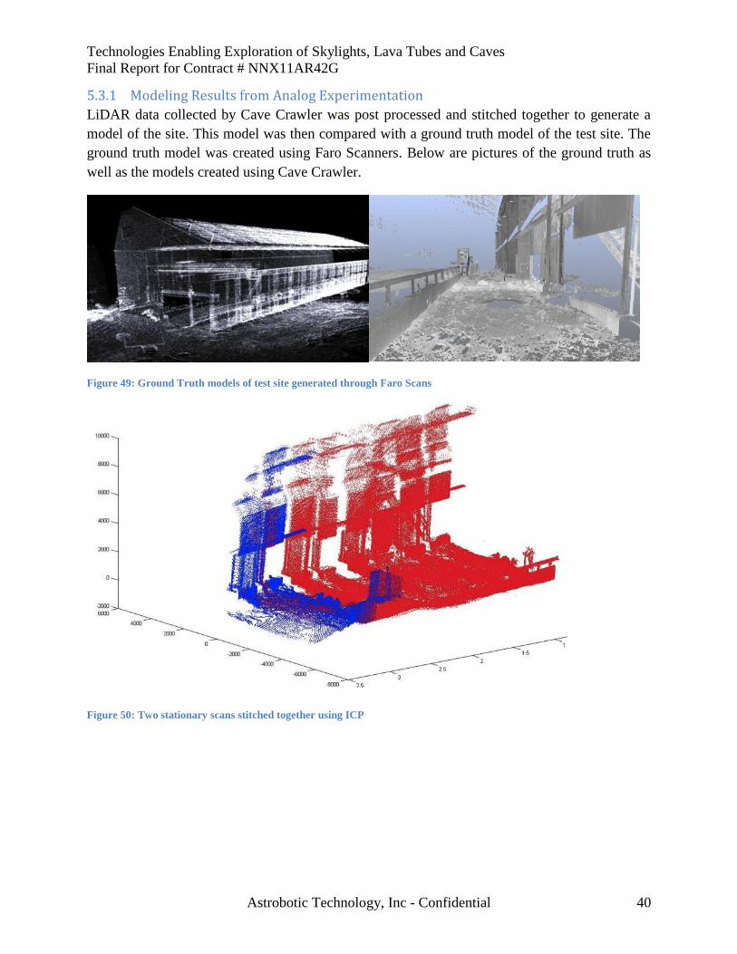
Technologies Enabling Exploration of Skylights, Lava Tubes and Caves
Final Report for Contract # NNX11AR42G
Astrobotic Technology, Inc - Confidential 40
5.3.1 Modeling Results from Analog Experimentation
LiDAR data collected by Cave Crawler was post processed and stitched together to generate a
model of the site. This model was then compared with a ground truth model of the test site. The
ground truth model was created using Faro Scanners. Below are pictures of the ground truth as
well as the models created using Cave Crawler.
Figure 49: Ground Truth models of test site generated through Faro Scans
Figure 50: Two stationary scans stitched together using ICP
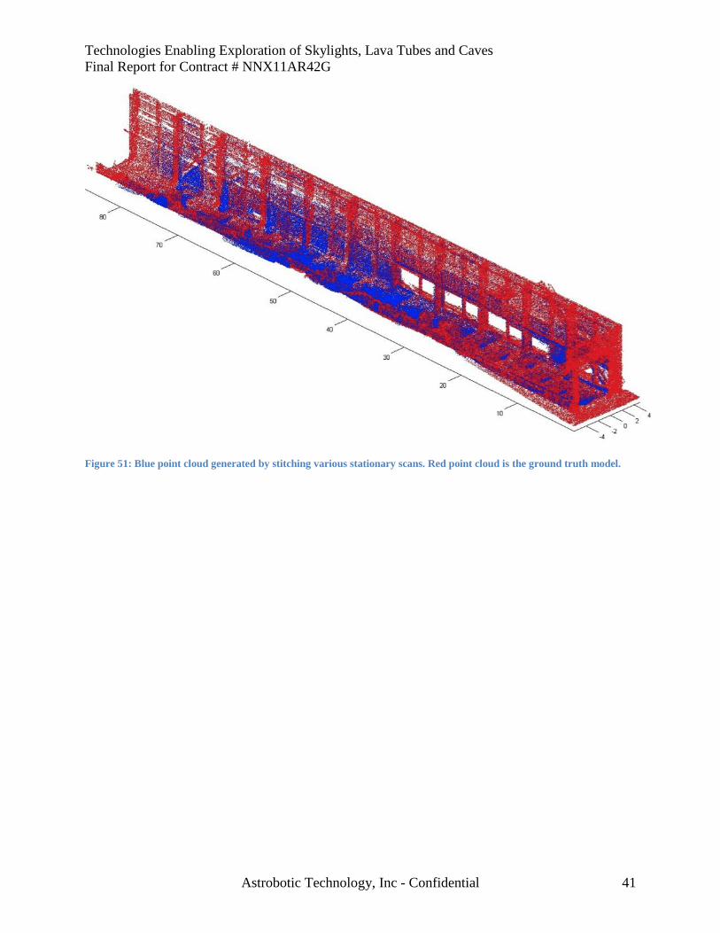
Technologies Enabling Exploration of Skylights, Lava Tubes and Caves
Final Report for Contract # NNX11AR42G
Astrobotic Technology, Inc - Confidential 41
Figure 51: Blue point cloud generated by stitching various stationary scans. Red point cloud is the ground truth model.
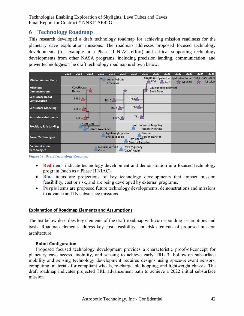
Technologies Enabling Exploration of Skylights, Lava Tubes and Caves
Final Report for Contract # NNX11AR42G
Astrobotic Technology, Inc - Confidential 42
6 Technology Roadmap This research developed a draft technology roadmap for achieving mission readiness for the
planetary cave exploration missions. The roadmap addresses proposed focused technology
developments (for example in a Phase II NIAC effort) and critical supporting technology
developments from other NASA programs, including precision landing, communication, and
power technologies. The draft technology roadmap is shown below.
Figure 52: Draft Technology Roadmap
Red items indicate technology development and demonstration in a focused technology
program (such as a Phase II NIAC).
Blue items are projections of key technology developments that impact mission
feasibility, cost or risk, and are being developed by external programs.
Purple items are proposed future technology developments, demonstrations and missions
to advance and fly subsurface missions.
Explanation of Roadmap Elements and Assumptions
The list below describes key elements of the draft roadmap with corresponding assumptions and
basis. Roadmap elements address key cost, feasibility, and risk elements of proposed mission
architecture.
Robot Configuration Proposed focused technology development provides a characteristic proof-of-concept for
planetary cave access, mobility, and sensing to achieve early TRL 3. Follow-on subsurface
mobility and sensing technology development requires designs using space-relevant sensors,
computing, materials for compliant wheels, re-chargeable hopping, and lightweight chassis. The
draft roadmap indicates projected TRL advancement path to achieve a 2022 initial subsurface
mission.
Technologies Enabling Exploration of Skylights, Lava Tubes and Caves
Final Report for Contract # NNX11AR42G
Astrobotic Technology, Inc - Confidential 43
Modeling Proposed focused technology development provides a characteristic proof-of-concept for
cave modeling with limited sensing capability and sparse data to achieve early TRL 3. Follow-on
development will refine techniques and demonstrate model reconstruction on full-scale problems
in analogous environments. Space-relevant sensing and computing will be used. The draft
roadmap indicates projected TRL advancement path to achieve a 2022 initial subsurface mission.
Autonomy Proposed focused technology development provides a characteristic proof-of-concept for
planning to model subsurface environments from a lightweight, highly mobile platform and
planning for safe hopping to achieve early TRL 3. Follow-on development refines control
approaches, develops algorithms and integrates supporting software elements. Technologies are
demonstrated on full-scale problems in analogous environments. The draft roadmap indicates
projected TRL advancement path to achieve a 2022 initial subsurface mission.
Precision, Safe Landing
Autonomous terrain relative navigation and hazard avoidance technologies are essential
for landing near a skylight rim. They are currently under development by NASA’s ALHAT
group and private enterprises, including Astrobotic Technology. These technologies are
estimated to reach TRL 6 by 2013-2014, prior to a robotic landed lunar mission in 2015-2016.
Autonomous mapping and re-planning technology enables rapid mapping and route
planning for the surface robot prior to selecting a landing site, reducing the risk involved in
reaching the skylight from the landing site. 2018 milestone assumes sufficient technology
advancement for mission objectives.
Power Technologies
High energy density batteries enable longer cave excursions with low battery masses.
NASA is funding multiple applicable battery development programs, in accordance with NASA
roadmap element 3.2.1 Batteries.
Power beaming enables recharging of subsurface robots from a solar powered lander. Power
beaming is under development by several groups including LaserMotive, who won the NASA
Power Beaming Challenge and are presently working for NASA to design the architecture to use
lasers to launch rockets and power satellites, and, eventually, power lunar bases (LaserMotive,
2012). This advancement dramatically increases the capability of the proposed mission by
enabling recharge of subsurface robots from a solar powered surface base.
Lightweight power and data cabling enables deploying tethered Livewire robots into
subsurface voids to establish power and communication nodes. Low mass reliable cabling will
reduce mission cost and risk. This is a key NASA technology development associated with
planetary base infrastructure and is associated with NASA roadmap element 3.3.3, Power
Distribution and Transmission.
Technologies Enabling Exploration of Skylights, Lava Tubes and Caves
Final Report for Contract # NNX11AR42G
Astrobotic Technology, Inc - Confidential 44
Communication Technologies
Surface to surface radio enables communication from a base inside the tube to mobile
subsurface explorers. Surface radios are under development at NASA JSC.
Low Frequency “cave” radio enables communication from a base inside the tube to mobile
subsurface explorers to pass through some rock obstructions. This reduces risk associated with
communication loss.
Missions
Lunar Robotic Precursor | A robotic mission to the lunar surface demonstrating
precision, safe landing on the Moon.
Spelunker Lunar Mission | The Spelunker mission concept at a lunar skylight.
Subsurface Mars Mission | The Spelunker mission concept, as refined by lunar
experience, applied to exploration of a Mars skylight.
7 References Ashley, J. W., Boyd, A. K., Hiesinger, H., Robinson, M. S., Tran, T., van der Bogert, C. H., et al.
(2011). Lunar Pits: Sublunarean Voids and the Nature of Mare Emplacement. Lunar and
Planetary Science Conference. The Woodlands, TX.
Ashley, J., Robinson, M., Hawke, B., Boyd, A., Wagner, R., & Speyerer, E. (2011). Lunar Caves
in Mare Deposits Imaged by the LROC Narrow Angle Cameras. First International Planetary
Cave Research Workshop. Carlsbad, NM.
Bleacher, J., Greeley, R., Williams, D., Cave, S., & Neukum, G. (2007). Trends in effusive style
at the Tharsis Montes, Mars, and implications for the development of the Tharsis province.
Journal of Geophysical Research, v. 112 .
Bleacher, J., Greeley, R., Williams, D., Werner, S., Hauber, E., & Neukum, G. (2007). Olympus
Mons, Mars: Inferred changes in late Amazonian aged effusive activity from lava flow mapping
of Mars Express High Resolution Stereo Camera data. Journal of Geophysical Research, v. 112 .
Coombs, C. R., & Hawke, B. R. (1992). A Search for Intact Lava Tubes on the Moon: Possible
Lunar Base Habitats. The Second Conference on Lunar Bases and Space Activities of the 21st
Century (pp. 219-229). Houston, Texas: NASA.
Cushing, G. E. (2012). Candidate cave entrances on Mars. Journal of Cave and Karst Studies ,
33-47.
Cushing, G. E., Titus, T. N., & Maclennan, E. (2011). Orbital Observations of Martian Cave-
entrance Candidates. First International Planetary Caves Workshop. Carlsbad, NM.
Technologies Enabling Exploration of Skylights, Lava Tubes and Caves
Final Report for Contract # NNX11AR42G
Astrobotic Technology, Inc - Confidential 45
Diebel, J., & Thrun, S. (2005). An Application of Markov Random Fields to Range Sensing.
Neural .
Dubowsky, S., Iagnemma, K., & Boston, P. J. (2006). Microbots for Large-Scale Planetary
Surface and Subsurface Exploration, NIAC Phase I.
Dubowsky, S., Plante, J., & Boston, P. (2006). Low Cost Micro Exploration Robots for Search
and Rescue in Rough Terrain. IEEE International Workshop on Safety, Security and Rescue
Robotics. Gaithersburg, MD.
Fairfield, N., Kantor, G. A., & Wettergreen, D. (2007). Real-Time SLAM with Octree Evidence
Grids for Exploration in Underwater Tunnels. Journal of Field Robotics .
Fairfield, N., Kantor, G. A., & Wettergreen, D. (2010). Segmented SLAM in Three-Dimensional
Environments. Journal of Field Robotics .
Fairfield, N., Kantor, G. A., & Wettergreen, D. (2005). Three Dimensional Evidence Grids for
SLAM in Complex Underwater Environments. International Symposium of Unmanned
Untethered Submersible Technology.
Fairfield, N., Kantor, G. A., & Wettergreen, D. (2006). Towards Particle Filter SLAM with
Three Dimensional Evidence Grids in a Flooded Subterranean Environment. International
Conference on Robotics and Automation.
Gould, S., Baumstarck, P., Quigley, M., & al., e. (2008). Integrating Visual and Range Data for
Robotic Object Detection. In Proc. ECCV.
Jones, H. L., Wong, U., Peterson, K. M., Koenig, J., Sheshadri, A., & Whittaker, W. L. (2012).
Complementary Flyover and Rover Sensing for Superior Modeling of Planetary Features. Field
and Service Robotics. Matsushima, Japan.
LaserMotive. (2012). Laser Power Beaming Fact Sheet. Retrieved from www.lasermotive.com
Li, S. (2001). Markov Random Field Modeling in Image Analysis.
Lowe, D. G. (2004). Distinctive image features from scale-invariant keypoints. International
Journal of Computer Vision, 60, 2 , (pp. 91-110).
Mitchell, L., & Malaska, M. (2011). Karst on Titan. First Intl. Planetary Caves Workshop.
Carlsbad, NM.
Morris, A., Ferguson, D., Silver, D., & Thayer, S. (2006). Topological Exploration of
Subterranean Environments. Journal of Field Robotics , 395-415.
(1968). NASA Surveyor Project Final Report. NASA Jet Propulsion Laboratory.
Technologies Enabling Exploration of Skylights, Lava Tubes and Caves
Final Report for Contract # NNX11AR42G
Astrobotic Technology, Inc - Confidential 46
Nuchter, A., & Surmann, H. (2004). 6D SLAM with an Application in Autonomous Mine
Mapping. New Orleans, LA: Proceedings of ICRA.
Oberbeck, V., Quaide, W., & Greeley, R. (1969). On the origin of Lunar sinuous rilles. Modern
Geology, v. 1 , p. 75–80.
Peterson, K. M., Jones, H. L., & Whittaker, W. L. (2011). MISSION DESIGN FOR
COMBINED LANDER-ROVER MODELING OF A SKYLIGHT. First International Planetary
Cave Research Workshop. Carlsbad, NM.
Reed, I. S., & Solomon, G. (1960). Polynomial Codes Over Certain Finite Fields. Journal of the
Society for Industrial and Applied Mathematics , 300-304.
Riris, H., Cavanaugh, J., Sun, X., Liivia, P., Rodriguez, M., & Neuman, G. (2010). The Lunar
Orbiter Laser Altimeter (LOLA) on nasa’s lunar reconnaissance orbiter (LRO) mission. Intl.
Conf. on Space Optics. Rhodes, Greece.
Robinson, M. S., Ashley, J. W., Boyd, A. K., Wagner, R. V., Speyerer, E. J., Hawke, B. R., et al.
(2012). Confirmation of sublunarean voids and thin layering in mare deposits. Planetary and
Space Science , 18-27.
Robinson, M., Brylow, S., Tschimmel, M., Humm, D., Lawrence, S., Thomas, P., et al. (2010).
Lunar Reconnaissance Orbiter Camera (LROC) instrument overview. Space Science Rev. 150.
Scherer, S., Chamberlain, L., & Singh, S. (2010). Online Assessment of Landing Sites. AIAA
Infotech@Aerospace. Atlanta, GA.
Sheshadri, A., Peterson, K. M., Jones, H. L., & Whittaker, W. L. (2012). Position Estimation by
Registration to Planetary Terrain. IEEE International Conference on Multisensor Fusion and
Information Integration.
Thrun, S., Thayer, S., Whittaker, W., Baker, C., Burgard, W., Ferguson, D., et al. (2004,
December). Autonomous Exploration and Mapping of Abandoned Mines. IEEE Robotics and
Automation Magazine , pp. 79-91.
Torres-Mendez, L., & Dudek, G. (2008). Inter-Image Statistics for 3D Environment . IJCV.
Ultra Electronics Maritime Systems, Inc. (2009). Magneto-Inductive Rock Phone Datasheet.
Dartmouth, Nova Scotia, Canada.
Wagner, M. D., Apostolopoulos, D., Shillcutt, K., Shamah, B., Simmons, R., & Whittaker, W. ".
(2001). The Science Autonomy System of the Nomad Robot. IEEE International Conference on
Robotics and Automation. Seoul, Korea.
Technologies Enabling Exploration of Skylights, Lava Tubes and Caves
Final Report for Contract # NNX11AR42G
Astrobotic Technology, Inc - Confidential 47
Wang, Y. L. (2011). Frontier-based Multi-Robot Map Exploration Using Particle Swarm
Optimization. IEEE Symposium on Swarm Intelligence (SIS). Paris, France.
Werker, J. C., Welch, S. M., Thompson, S. L., Sprungman, B., Hildreth-Werker, V., Frederick,
R. D., et al. (2003). Extraterrestrial caves: Science, habitat, and resources (a NIAC phase I
study). Environmental Sustainability Publications.
Wettergreen, D., Cabrol, N., Baskaran, V., Calderon, F., Heys, S., Jonak, D., et al. (2005).
Second Experiments in the Robotic Investigation of Life in the Atacama Desert in Chile.
International Symposium on Artificial Intelligence, Robotics and Automation in Space. Munich,
Germany.
Wong, U. Y. (2012). Lumenhancement: Exploiting Appearance for Planetary Modeling.
Pittsburgh, PA: Carnegie Mellon University.
Wong, U., Garney, B., Whittaker, W., & Whittaker, R. (2009). Camera and LIDAR Fusion for
Mapping of Actively Illuminated Subterranean Voids. Proc. Field and Service Robotics.
Wong, U., Garney, B., Whittaker, W., & Whittaker, R. (2011). Image-Directed Sampling for
Geometric Modeling of Lunar Terrain.
Wong, U., Morris, A., Lea, C., Whittaker, W., Garney, B., & Whittaker, W. ". (2011).
Comparative evaluation of range sensing technologies for underground void modeling.
International Conference on Intelligent Robotics and Systems, (pp. 3816-3823). San Francisco,
California.
Yang, Q., Yang, R., Davis, J., & Nister, D. (2007). Spatial-Depth Super Resolution for Range
Images. Proc. IEEE CVPR.
Zlot, R., & Bosse, M. (2012). Efficient Large-Scale 3D Mobile Mapping and Surface
Reconstruction of an Underground Mine. Field and Service Robotics. Matsushima, Japan.