Embed Size (px)
Citation preview

Technische Universität München
Computer Graphics
Computer GraphicsSS 2014
Graphics Effects
Rüdiger WestermannLehrstuhl für Computer Graphik und Visualisierung

Technische Universität München
Computer Graphics
2
Advanced graphics effects
Effects which are not provided natively by the rasterization based graphics pipeline• Scene reflections • Shadows

Technische Universität München
Computer Graphics
3
Advanced graphics effects
Reflections• Note the difference between local illumination
and scene reflection– Local illumination considers the reflection of direct light– Scene reflection considers the reflection of the scene
• Problem: which scene point reflects in an object point

Technische Universität München
Computer Graphics
4
Advanced graphics effects
• Scene reflections using rasterization based pipeline– Rasterization based pipeline projects scene onto the image
plane– Camera position is projection center for all scene parts, ie.
single view projection– To simulate scene reflections, the scene has to be rendered
from multiple views, ie. from each object point that reflects towards the viewer
– Requires many rendering passes,and is too costly in general

Technische Universität München
Computer Graphics
5
Advanced graphics effects
• Planar reflections– Reflect the scene about a planar mirror
• Basic algorithm: flip scene through the mirror and re-render

Technische Universität München
Computer Graphics
6
Advanced graphics effects
• Reflect of scene at the mirror plane requires finding the reflection matrix
• Re-render reflected scene but restrict drawing to the pixels through which the mirror is seen
Mirror
Reflected scene
Wall

Technische Universität München
Computer Graphics
7
Advanced graphics effects
• The reflection matrix– p[3]: point on plane– n[3]: plane normal– d: n·p
– Multiply reflection matrix with modeling matrix
1000
]2[2]2[]2[21]1[]2[2]0[]2[2
]1[2]2[]1[2]1[]1[21]0[]1[2
]0[2]2[]0[2]1[]0[2]0[]0[21
ndnnnnnn
ndnnnnnn
ndnnnnnn

Technische Universität München
Computer Graphics
8
Advanced graphics effects
• Restrict drawing of the flipped scene to the pixels through which the mirror is seen

Technische Universität München
Computer Graphics
9
Advanced graphics effects
• Restricted drawing via the stencil test– Stencil buffer: stores for each pixel a bit-mask – A stencil test can be performed after the depth test
for each fragment
Color buffer
Depth buffer
Stencil buffer

Technische Universität München
Computer Graphics
10
Advanced graphics effects
• Typical use of the stencil buffer/test
stencil = 1
InitializeStencil buffer Render pass 1 Render pass 2
Test: ref = 0;
stencil == ref
Test:ref = 1;
stencil == ref

Technische Universität München
Computer Graphics
11
Advanced graphics effects
Mirror rendering algorithm
A) Initialize modelview matrix, enable depth/stencil testing B) Render mirror to mask all covered pixels in stencil buffer
mask = 1

Technische Universität München
Computer Graphics
12
Advanced graphics effects
Mirror rendering algorithm
C) Multiply modeling matrix with reflection matrix to flip the sceneD) Render scene where pixels have been mask*
*clip everything in front of the mirror plane using a clip-plane

Technische Universität München
Computer Graphics
13
Advanced graphics effects
Mirror rendering algorithm
E) Reset modeling matrix to initial stateF) Render scene where pixels have not been mask
+ =

Technische Universität München
Computer Graphics
14
Advanced graphics effects
• Non planar reflections

Technische Universität München
Computer Graphics
15
Advanced graphics effects
• Environment mapping: – Simulate an infinitely small reflecting sphere in the center of
the scene to be reflected
– Compute (or measure) and store in a texture the incoming light at the sphere for all directions
– At run-time, for a given reflection vector look-up the stored light from the texture and use as fragment color
Θ
(𝜃 ,𝜙)
Spherical coordinates
(𝜃 ,𝜙)

Technische Universität München
Computer Graphics
16
Advanced graphics effects
• Cube maps– An alternative to environment maps which can be generated
very efficiently using rendering functionality
– Captures the incoming light through 6 faces of a cube centeredat the environment center
– Generated by rendering the scene 6 times from the cube center, with the respective cube face being the viewport

Technische Universität München
Computer Graphics
17
Advanced graphics effects
• See alsohttp://en.wikipedia.org/wiki/Cube_mapping

Technische Universität München
Computer Graphics
18
Advanced graphics effects
• Cube map is stored in 6 2D textures
• Cube map access:– For each fragment compute the reflection vector R– The largest component of R selects the cube face– By dividing the other components through the largest, the 2D
texture coordinate in the selected face is given

Technische Universität München
Computer Graphics
19
Advanced graphics effects
Cube map texture coordinates:• Compute reflection vector
major axis s t ma ---------------------------------------------------------------------------- positive_X negative_X positive_Y negative_Y positive_Z negative_Z
s = ( s/|ma| + 1 ) / 2 and t = ( t/|ma| + 1 ) / 2

Technische Universität München
Computer Graphics
20
Advanced graphics effects
• Cube map examples

Technische Universität München
Computer Graphics
21
Advanced graphics effects
Effects which are not provided natively by the rasterization based graphics pipeline• Scene reflections • Shadows

Technische Universität München
Computer Graphics
22
Advanced graphics effects
• Why shadows?

Technische Universität München
Computer Graphics
23
Advanced graphics effects
• Shadows and visibility: Remember, the depth-test resolves visibility on a per-fragment basis– z-buffer stores minimum z-value of all fragments
projecting into the same pixel– Testing during fragment processing
• Frustum (perspective) transformation preserves z-ordering
• Incremental z-value update (if fragment is closer to near plane than current one)
– Visibility is with respect to the viewer

Technische Universität München
Computer Graphics
24
Advanced graphics effects
z-buffer algorithm:colorbuffer BackgroundColorz-buffer 1
foreach polygonforeach fragmentx,y // generated by the
rasterizerz = fragmentx,y.depth
if z < z-buffer[x,y] then // depth testz-buffer[x,y] = zcolorbuffer[x,y] = fragmentx,y.color

Technische Universität München
Computer Graphics
25
Advanced graphics effects
• Visibility: which objects can be seen from the view point?• Shadows: which objects can be seen from the light source?
© Bertrand Clerc Designhttp://bertrandclerc.com/interaction/shades-of-vauxhall/

Technische Universität München
Computer Graphics
26
Advanced graphics effects
• Shadow mapping– Simulates shadows in two rendering passes
(1)Renders the scene from the light source position to determine all fragments which are not in shade, ie. which are seen by the light
(2)Renders the scene from the camera position and tests each generated fragment whether it was seen or not in the first pass- If it was seen in the first pass it receives light,
otherwise it is in shade and its color is darkened- The test simply checks whether in the first pass
there was a fragment closer to the light than the current fragment
Technische Universität München
Computer Graphics
27
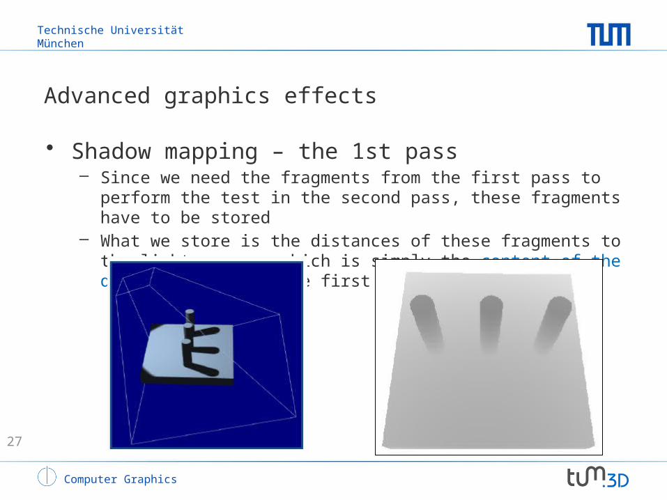
Advanced graphics effects
• Shadow mapping – the 1st pass– Since we need the fragments from the first pass to perform
the test in the second pass, these fragments have to be stored
– What we store is the distances of these fragments to the light source, which is simply the content of the deph buffer after the first pass

Technische Universität München
Computer Graphics
28
Advanced graphics effects
• Shadow mapping – the 1st pass:the depth buffer after the first rendering pass is stored in a texture map – the shadow map– In DX this can be realized by a pixel shader that computes the
fragments depth values and writes these values into a texture resource instead of the color buffer
– First, set up the description of the texture, then create that texture, and finally use the texture to setup a render target view
– The so-generated texture can then be made accessible to a pixel shader in the second rendering pass
Technische Universität München
Computer Graphics
29
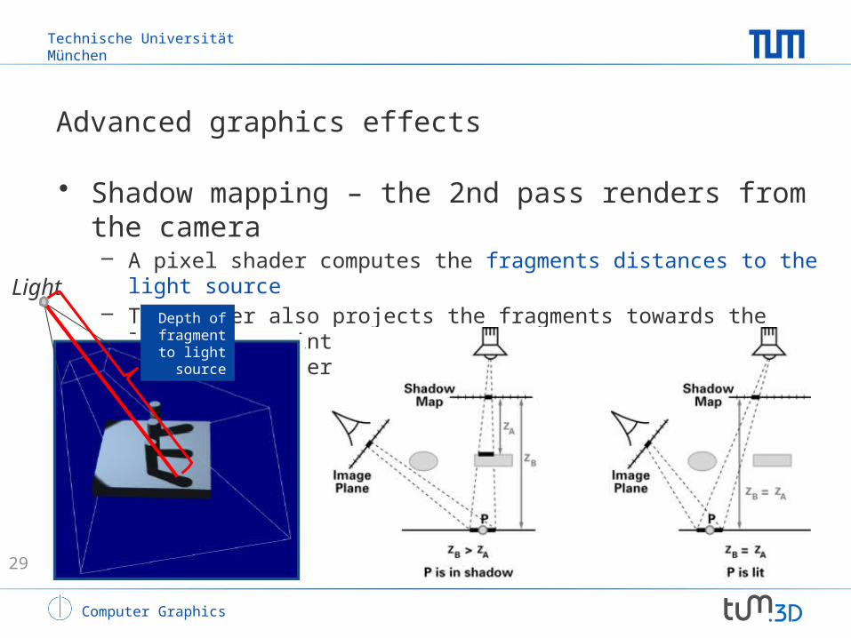
Advanced graphics effects
• Shadow mapping – the 2nd pass renders from the camera– A pixel shader computes the fragments distances to the light
source– The shader also projects the fragments towards the light source
into the shadow map – the fragments coordinate after projection is used as texture coordinate into the shadow map
LightDepth of fragment
to light source

Technische Universität München
Computer Graphics
30
Advanced graphics effects
• Shadow mapping – the 2nd pass– Finally, the shader compares the fragments depth with the
depth stored in the shadow map and decides whether it is in shade or not
Light
Depth in shadow map
Depth of fragment
to light source

Technische Universität München
Computer Graphics
31
Advanced graphics effects
• Shadow mapping– Requires one additional rendering pass per light source– Can only be used in combination with point light sources– Artefacts can occur due to the resolution of the shadow map
4096x40961024x1024

Technische Universität München
Computer Graphics
Shadow volumes
• Shadow volumes– Relies on a geometric representation of the spatial
region that is shadowed by an object– Shadow polyhedra is generated by projecting the
objects´ shilouette edges (as seen from the light source) onto the shadowed surface and connecting the respective points
– Shadow algorithm now tests whether object points, ie. fragments, are inside or outside a shadow volume

Technische Universität München
Computer Graphics
Shadow volumes
• Shadow volumes

Technische Universität München
Computer Graphics
Shadow volumes
• Shadow volume geometry
Without shadows Shadow volume Final scene

Technische Universität München
Computer Graphics
Shadow volumes
• When is a point in shadow?• Shadow volume algorithm [Crow 1977]
– Intersect the rays from the eye with shadow volume boundaries
– For each ray • Start with counter = 0, and increment/decrement
the counter at every shadow volume front/back face• If ray hits an object and counter == 0, then the
object point is not in shadow

Technische Universität München
Computer Graphics
Shadow volumes
• Algorithm [Heidmann 91]1. Render the unlit scene and clear the stencil buffer2. Loop over all light sources
• Clear stencil buffer, disable depth write and color write but leave depth test enabled
• Render front-facing polygons of the shadow volume and increment the stencil where they pass the depth test
• Render back-facing polygons of the shadow volume and decrement the stencil where they pass the depth test
• Render the lit scene where stencil value = 0 (with additive blending)
• Note: – Stencil value classifies fragments as shadowed or unshadowed
• Shadowed pixels end up with non-zero stencil

Technische Universität München
Computer Graphics
Shadowing object Light
source
Eyeposition
zero
zero
+1
+1+2 +2
+3
Unshadowedobject
+ ---+ +
Shadow Volume Count = +1+1+1-1-1-1 = 0
Illuminated (Behind Shadow Volumes)

Technische Universität München
Computer Graphics
Shadowing object Light
source
Eyeposition
zero
zero
+1
+1+2 +2
+3
Shadowedobject
+ -+ +
Shadow Volume Count = +1+1+1-1 = 2
Shadowed (inside Shadow Volumes)

Technische Universität München
Computer Graphics
Shadowing object Light
source
Eyeposition
zero
zero
+1
+1+2 +2
+3
Unshadowedobject
Shadow Volume Count = 0
Illuminated (before Shadow Volumes)