Embed Size (px)
Citation preview

Teemu Turkia
TECHNIQUES AND DESIGN PATTERNS IN GAME ENGINE
PROGRAMMING
Bachelor’s Thesis
Degree Programme in Information Technology / Game Programming
April 2016

Tekijä/Tekijät Tutkinto Aika
Teemu Turkia
Insinööri huhtikuu 2016
Opinnäytetyön nimi Tekniikat ja suunnittelumallit pelimoottoriohjelmoinnissa
79 sivua 1 liitesivu
Toimeksiantaja Kymenlaakson Ammattikorkeakoulu
Ohjaaja Yliopettaja Paula Posio
Tiivistelmä Opinnäytetyön tavoitteena oli tutkia pelimoottorien päärakenteita sekä toimiviksi havaittujen ohjelmointitekniikoiden ja suunnittelumallien soveltamista niihin. Kehittäjillä on tänä päivänä mahdollisuus valita useista saatavilla olevista yleiskäyttöisistä pelimoottoreista mieleisensä, mutta pohjan rakentaminen pelille itse auttaa ymmärtämään pelimoottorien matalan tason rakenteita ja vapauttaa kehittäjäryhmän mahdollisista lisenssimaksuista. Työssä käytettiin toteutuksellista lähestymistapaa, minkä seurauksena ohjelmoitiin yksinkertainen, mutta täysin toimiva pelimoottori. Toteutetun moottorin tuli sisältää tarvittavat ominaisuudet ollakseen käytettävissä videopelin pohjaksi. Päämääränä oli samalla tuottaa uudelleenkäytettävää ja helposti tulkittavaa ohjelmakoodia. Muita tavoitteita olivat oppimateriaalin tuottaminen, ohjelmointitaitojen kehittäminen ja uusien ratkaisujen löytäminen pelimoottorin rakenteiden luomisessa kohdattuihin ongelmiin. Työ toteutettiin tutkimalla ja soveltamalla hyväksi havaittuja suunnittelumalleja ja ohjelmointitekniikoita erilaisten alijärjestelmien, rakenteiden ja aputyökalujen luomiseen, joista pelimoottori koostuu. Pelimoottorisuunnitteluun liittyviin ongelmiin kokeiltiin erilaisia ratkaisuja ja niiden hyödyt ja haitat punnittiin. Suurin osa opinnäytetyön tavoitteista saavutettiin, tärkeimpänä perusominaisuuksilla varustetun toimivan pelimoottorin ohjelmoiminen. Havaittiin, että suositellut tekniikat eivät yleensä tarjoa valmiita ratkaisuja pelimoottoriohjelmoinnissa kohdattaviin ongelmiin, vaan niitä täytyy osata soveltaa oikeisiin kohteisiin. Tarjotut menetelmät ovat kuitenkin erittäin tehokkaita, jos ohjelmoija ymmärtää niiden hyödyt ja haitat. Tämän dokumentin lukijalla oletetaan olevan ymmärrys C++:sta tai vastaavasta ohjelmointikielestä sekä pelimoottoreihin liittyvistä perusasioista. Suurin osa aihealueista ei käsittele C++-kieltä suoranaisesti, mutta termejä, kuten osoittimia, muistialueita ja malleja (template) käytetään tekstissä ilman erillisiä selityksiä.
Asiasanat pelimoottori, suunnittelumalli, peliohjelmointi, C++

Author (authors) Degree Time Teemu Turkia
Degree Programme in Information Technology
April 2016
Thesis Title Techniques and Design Patterns in Game Engine Programming
79 pages 1 page of appendices
Commissioned by Kymenlaakso University of Applied Sciences
Supervisor Paula Posio, Principal Lecturer
Abstract The objective of this thesis was to examine the core structure of a game engine and applications of various design patterns and techniques. While various general-purpose game engines exist for game development teams to use freely, programming a custom base for a game helps to understand the functionality low-level engine systems as well as frees the team of possible licensing costs. A development approach was taken in implementing the thesis, meaning a complete, yet simple game engine has been programmed from inception while creating this document. The provided engine would be equipped with fundamental features to enable it to work as a base for a video game, while providing reusable and easily interpretable code. Additional goals included creating learning material, refining programming skills and exploring new ways to implement game engine features. The method used to carry out the study included applying proven design patterns and techniques to implement various subsystems, structures and utilities that comprise a game engine. Different approaches to various problems related to game engine design were considered and their benefits and flaws weighed. Most of the goals set for this thesis were met, the most important being creating a working game engine providing basic functionality by the end of the project. It was perceived that most of the techniques recommended to be used in game engine programming do not offer complete solutions to issues, and must be used to resolve appropriate problems. However, when these techniques understood by the programmer and applied properly, they are typically proven to be powerful. The reader of this document is expected to be familiar with the C++ programming language or similar as well as the basic concept of a game engine. Most of the topics do not deal directly with C++ features, but subjects such as pointers, memory layout and templates are discussed with no explicit explanations.
Keywords game engine, design pattern, game programming, C++

TABLE OF CONTENTS
1 INTRODUCTION .......................................................................................................... 7
1.1 Challenges .............................................................................................................. 7
1.2 Motivation ............................................................................................................... 8
2 TOOLS AND LIBRARIES ............................................................................................. 8
3 PROJECT SETUP ...................................................................................................... 10
3.1 Directory structure ................................................................................................ 10
3.2 Build types ............................................................................................................ 11
3.3 Version control ...................................................................................................... 12
3.4 Project branching .................................................................................................. 12
4 PROGRAMMING STYLE ........................................................................................... 13
4.1 General guidelines ................................................................................................ 13
4.2 Inheritance ............................................................................................................ 13
4.3 Type definitions ..................................................................................................... 13
4.4 Naming convention ............................................................................................... 14
4.5 Error handling ....................................................................................................... 15
4.5.1 Logging .......................................................................................................... 16
4.5.2 Assertions ...................................................................................................... 17
4.6 Object memory layout ........................................................................................... 17
4.7 Code documentation ............................................................................................. 18
5 ENGINE STRUCTURE ............................................................................................... 19
5.1 Engine overview ................................................................................................... 19
5.2 Game Loop ........................................................................................................... 20
5.3 Update Method ..................................................................................................... 22
5.4 Data Locality ......................................................................................................... 23
5.5 Custom memory allocation ................................................................................... 27
5.6 Game objects and the Component pattern ........................................................... 30
5.6.1 Downsides of the pure component model ...................................................... 33
5.6.2 Template metaprogramming and typelists ..................................................... 36

5.6.3 Property-centric design .................................................................................. 40
5.7 Engine messaging systems .................................................................................. 40
5.7.1 Service Locator .............................................................................................. 40
5.7.2 Event Queue .................................................................................................. 41
5.8 Thread safety ........................................................................................................ 43
5.8.1 Common multithreading issues ...................................................................... 43
5.8.2 Concurrent containers .................................................................................... 44
6 RENDERING SYSTEM .............................................................................................. 47
6.1 Application window ............................................................................................... 47
6.2 Renderer initialization ........................................................................................... 47
6.3 Texture loading ..................................................................................................... 48
6.4 Scene rendering ................................................................................................... 48
6.4.1 Batching and optimization .............................................................................. 50
6.4.2 Flyweight pattern and instanced rendering..................................................... 54
6.5 Platform restrictions .............................................................................................. 56
6.6 Shortcomings of the rendering subsystem ............................................................ 56
7 PHYSICS ENGINE ..................................................................................................... 57
7.1 Attaching physics to game objects ........................................................................ 58
7.2 Force generators .................................................................................................. 58
7.3 Collision handling .................................................................................................. 59
7.3.1 Broad-phase collision tests and Spatial Partition ........................................... 61
7.3.2 Narrow-phase collision detection ................................................................... 64
7.3.3 Sleep state ..................................................................................................... 65
8 OTHER SYSTEMS AND UTILITIES ........................................................................... 66
8.1 Input ...................................................................................................................... 67
8.2 Utility classes and functions .................................................................................. 68
8.2.1 Handles .......................................................................................................... 68
8.2.2 Random number generation ........................................................................... 70
8.3 Unimplemented engine features ........................................................................... 71
8.3.1 Resource manager ......................................................................................... 71

8.3.2 Audio engine .................................................................................................. 71
8.3.3 User interface ................................................................................................. 72
8.3.4 Networking ..................................................................................................... 72
9 CONCLUSIONS ......................................................................................................... 72
REFERENCES .................................................................................................................. 75
FIGURES ........................................................................................................................... 77
APPENDICES Appendix 1. Doxygen program code documentation
7
1 INTRODUCTION
The aim of the thesis was to examine the structures of a video game core
systems and various proven design patterns and techniques and creating a
working game engine applying that information. The requirements the engine
had to meet included implementing two-dimensional rendering, physics and
input systems while maintaining compatibility with the most common platforms
and finally creating a demo game using the engine. The thesis attempts to
explain the reasons for implementing each technique or pattern in the engine
while offering possible alternative approaches.
The goals of this thesis included helping to understand the fundamental basics
of game engine architecture, experimenting proven patterns and techniques
as well as creating reusable and interpretable code for future use. Selecting
the best programming patterns and techniques normally means having to
make a choice between multiple proven options based on the problem
(Nystrom 2014). One of the goals of this thesis was to weigh the benefits and
costs of certain techniques.
Additional objectives for the project included providing learning material,
refining general programming skills and learning, as well as possibly coming
up with new and unique patterns or techniques. The information gained from
the study helps working with existing commercial engines because of the
better understanding of their low-level systems. The study provided a
complete game engine base, which is extendable and can be used to create
simple two-dimensional games.
1.1 Challenges
The major challenges building an engine while studying its various
components are keeping with the planned timeline while producing readable
and reusable code (McShaffry 2013, 14). This must be achieved without
programming perfunctorily while trying to keep with the limited array of tools
chosen. In this particular project, keeping the system compatible with various
platforms presented another challenge as well as building a working game
based on the system.
8
1.2 Motivation
With the variety of advanced game engines and tools available today, it may
be argued that programming an engine from inception is pointless. While
using existing tools yields visible results faster, programming the engine itself
provides a development team invaluable experience and knowledge about the
low-level structures that exist in commercial engines. No universal game
engine best for all kind of games exists, and a tailored system can offer a
significant performance boost to a game when properly implemented. When
developing small-scale games such as mobile products, a custom engine may
also be more profitable, since developers must normally pay a price for
commercial engine licenses or commit to pay fees based on sales.
2 TOOLS AND LIBRARIES
The tools to implement the engine were selected with performance and control
over the project in mind. Other requirements included cross-platform support
and absence of licensing costs or other fees. These choices support
reusability of the engine and cause it to be more generic and easier to read by
users. Multi-platform support allows games to be built on desktop, mobile and
other environments with minimum effort: Almost all of the platform-specific
program code is related to rendering, while all other subsystems work on all of
the target platform with little or no special rules. This is important because of
the variety in devices today. The game engine programmed for this thesis
supports Windows, Linux, Mac OS X desktop platforms as well as Android
and iOS mobile devices that support OpenGL ES version 2.0 or higher.
C++
C++ was chosen as the language of the engine for multiple reasons. It is the
most popular programming language used game programming, thus proven to
be a good choice (Nystrom 2014, 6; Millington 2010, 11; Gregory 2014, 97).
The language is platform independent and has good performance since it is
close to the hardware (Graham 2013, 331-333). In addition, systems such as
custom memory allocators may require features like pointer and reference
handling or operator overloading, which are available in C++ (Gregory 2014,
239-254).

9 The language offers a standard template library for a range of complete
features such as data structures, containers and algorithms. While STL has a
lot of benefits, it may be slower than custom implementations, allocates a lot
of memory dynamically and might change the code implementation for
different platforms. (Gregory 2014, 261-262.) The engine utilizes STL with
caution.
OpenGL
Any game engine requires an API to draw graphics on the screen and the
choice for this engine was OpenGL. It is completely independent of the
operating system and is a C-language library, meaning it works seamlessly
with the C++ language and the objective for platform portability is maintained.
(Shreiner, Sellers, Kessenich & Licea-Kane 2013, 2-3.)
GLEW
OpenGL API changes constantly as the hardware manufacturers develop new
extensions. This causes compilers and platform specific libraries to be out of
sync with the new versions. To fix this problem, a mechanism to retrieve the
correct function pointers for each library and version was implemented. This
process is automated by an open-source library called OpenGL Extension
Wrangler, or GLEW. It both verifies the extension support of the system and
associates the correct function pointers and is used by this engine. (Shreiner
et al. 2013, 836-838.)
GLM
To simplify the code, avoid mistakes and save time, the engine uses the
OpenGL Mathematics library, which implements mathematics functions for
graphics software and is designed using the same naming conventions and
functionalities as the OpenGL Shading Language. (OpenGL Mathematics,
2016.)
SDL
Since OpenGL is a purely platform independent graphics library, it provides no
functionality for window creation or user input. In order to avoid programming
these features using only operating system specific code, a library called
Simple DirectMedia Layer 2.0 (SDL) was used. SDL supports a wide range of

10 platforms, including Windows, Mac OS X, Linux, iOS and Android. It offers
easy to use solutions for window creation, multiple monitors and user input.
(McDonald, Gledreich, Lantinga, 2013).
Sound
The audio subsystem was excluded from engine due to the broad nature of
this thesis. The most basic functionality such as threading, event messaging,
logging and initialization were implemented but the actual sound library to be
used was left undecided.
CppCheck
CppCheck is a tool used to analyze the code at compile time. It is used to
detect warnings in a more verbose and accurate way than most compilers do.
(CppCheck – A tool for static C/C++ code analysis, 2015.) This reduces the
amount of bugs, enforces better programming style and forces the source
code to be easier to interpret.
3 PROJECT SETUP
While the source code is the most important resource in a game engine,
preparation and setting up the project properly make the system easier to
build, maintain and use. One of the main reasons to build an engine is
reusability and a badly organized project may render the engine base too hard
to comprehend for future use. This is especially crucial if the project has
multiple users with different tasks, such as artists and testers. (McShaffry
2013, 98-100.)
3.1 Directory structure
A proper file structure helps keeping the project organized from start to finish
and keeps the different aspects from being mixed with each other. While
planning the directory structure is not crucial to the project, it makes
development smoother in the long run, especially when the product is an
actual game instead of an engine. (McShaffry 2013, 100-103.)

11
Figure 1. The directory structure applied for the development of this engine
The directory structure of this engine split the assets, documentation, engine
and game builds, source files, third party libraries, platform settings and
temporary files in their own directories, as seen in figure 1.
3.2 Build types
Commercial game projects typically have multiple builds for different
purposes. These typically consist of debug, release and production builds.
The debug build is a non-optimized version of the project providing maximum
amount of information about the running code. The release build runs faster
than the debug version and offers less information but still has some
debugging information and asserts turned on. The production build represents
the complete product to be used, offers no debugging information, and has the
maximum amount of optimizations and performance. (Gregory 2014, 78-79.)

12 This game engine implements debug, release and production builds as well as
a fourth one called profiling build. The profiling build offers even more
information than the debug build such as performance measurements and
visual representations of data structures and physics objects. The different
builds may have slight and unpredictable differences in their behavior and
some can produce bugs others do not, thus it is important to keep them all up
to date and test them equally (Gregory 2014, 80).
3.3 Version control
Version control allows multiple users to modify the same project and its
different files simultaneously without causing conflicts with the data currently
being modified. Other features version control tools offer include history in file
changes, reverting to previous versions, merging conflicting files and splitting
and cloning the project into multiple branches. Subversion, Git and Perforce
are examples of systems developed for version control purposes. (Gregory
2014, 63-65; McShaffry 2013, 110-111.)
The version control system used for the engine was Git. Although the multi-
user benefits were obsolete at the time of development, the other features are
extremely valuable in any software development project. In addition, version
control maintained an additional backup of the project files and
documentation.
3.4 Project branching
Version control tools allow detaching projects from the main development
branch, usually called the trunk. Branches are created by cloning the whole
source repository into a new project. This ensures that the projects do not
interfere in any way and branches can be used to work on new features,
radical core changes, patches or experimenting without risks of harmful
conflicts or breaking the code. The branches can later be merged with the
trunk if necessary. (McShaffry 2013, 115-118.)

13
4 PROGRAMMING STYLE
A consistent coding style is important in any programming project that is
planned to be reused later or read by other users (Graham 2013, 56-57). The
style discussed in this section covers decisions made regarding the visual
look, design, convenience, reuse and performance of the code prior to starting
the project.
4.1 General guidelines
Hiding expensive operations behind simple looking code such as getter
functions, constructors or operators was avoided. The user should be able to
grasp the performance and complexity of an operation from reading the code
(Graham 2013, 59-60). Functions created automatically be the compiler such
as default constructors were added manually.
4.2 Inheritance
Class hierarchies should be kept flat to avoid bloating the base classes and
having slight changes have a major impact on multiple classes (Graham 2013,
60-61). Composition was preferred over inheritance when possible due to the
expenses caused by virtual functions and polymorphism (Graham 2013, 61-
64; Nystrom 2014, 215-217, 277-289).
4.3 Type definitions
Custom definitions for common types were used to achieve better portability
and consistency as well as to avoid precision errors caused by inaccurate
types (Gregory 2014, 118-119, Millington 2010, 21). Examples of the custom
type definitions used in the engine are presented in table 1.
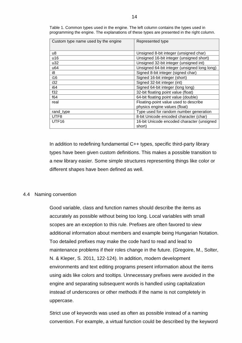
14 Table 1. Common types used in the engine. The left column contains the types used in programming the engine. The explanations of these types are presented in the right column.
Custom type name used by the engine Represented type
u8 Unsigned 8-bit integer (unsigned char)
u16 Unsigned 16-bit integer (unsigned short)
u32 Unsigned 32-bit integer (unsigned int)
u64 Unsigned 64-bit integer (unsigned long long)
i8 Signed 8-bit integer (signed char)
i16 Signed 16-bit integer (short)
i32 Signed 32-bit integer (int)
i64 Signed 64-bit integer (long long)
f32 32-bit floating point value (float)
f64 64-bit floating point value (double)
real Floating-point value used to describe physics engine values (float)
rand_type Type used for random number generation
UTF8 8-bit Unicode encoded character (char)
UTF16 16-bit Unicode encoded character (unsigned short)
In addition to redefining fundamental C++ types, specific third-party library
types have been given custom definitions. This makes a possible transition to
a new library easier. Some simple structures representing things like color or
different shapes have been defined as well.
4.4 Naming convention
Good variable, class and function names should describe the items as
accurately as possible without being too long. Local variables with small
scopes are an exception to this rule. Prefixes are often favored to view
additional information about members and example being Hungarian Notation.
Too detailed prefixes may make the code hard to read and lead to
maintenance problems if their roles change in the future. (Gregoire, M., Solter,
N. & Kleper, S. 2011, 122-124). In addition, modern development
environments and text editing programs present information about the items
using aids like colors and tooltips. Unnecessary prefixes were avoided in the
engine and separating subsequent words is handled using capitalization
instead of underscores or other methods if the name is not completely in
uppercase.
Strict use of keywords was used as often as possible instead of a naming
convention. For example, a virtual function could be described by the keyword

15 virtual in the last class deriving it but this could have the user assume more
classes are derived from it. The same conclusions could be made if the virtual
function had a prefix. Using the keyword virtual for base class virtual functions
and the keyword final for the classes that will not be derived corrects these
issues. Marking all functions as virtual is sometimes encouraged but doing this
would not describe the behavior accurately (Gregoire et al. 2011, 216).
Examples of the naming convention used in the engine are presented in table
2.
Table 2. Engine naming convention. The left column contains the type of the item that requires to be named. An example of an item name using the naming convention is presented in the right column.
Item Example name
Class ExampleClass
Function ExampleFunction()
Class member classMember
Macro UGLY_AND_VISIBLE
Enumerated type EListExample
Enumerated value EXAMPLE_ENUM_ITEM
Union UExampleUnion
The naming convention differs from the OpenGL syntax, where functions are
in lowercase and are sometimes named based on parameters, as the library
does not support function-overloading (Shreiner et al. 2013, 8-9). Low-level
OpenGL functions were separated from the base code when possible.
4.5 Error handling
The C++ exception handling feature was completely ignored in the engine
implementation. This was due to the overhead caused by the feature,
exceptions being hard to see in the source code and the fact that
implementing exception handling at some part of a program it must practically
be implemented everywhere else (Gregory 2014, 147-149). Critical errors
should be handled using assertions and other methods to catch user errors
(Gregory 2014, 151-152). Exceptions were handled in the engine by
implementing custom logging, error handling and assertion systems.
16
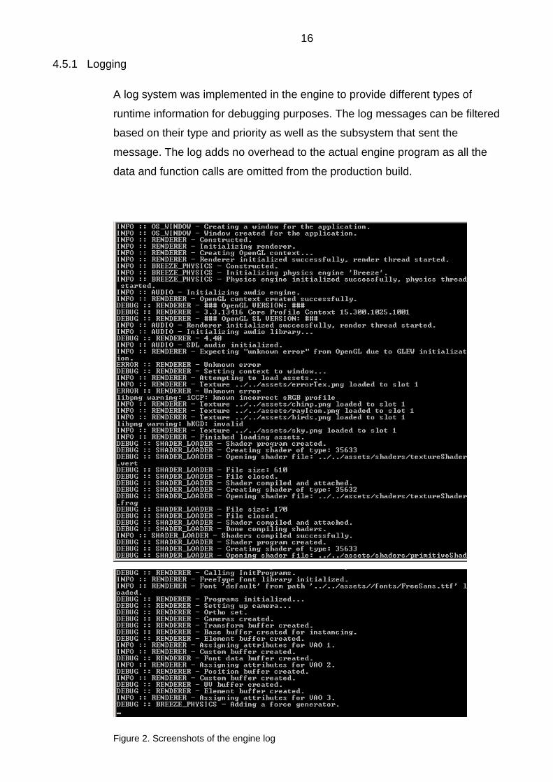
4.5.1 Logging
A log system was implemented in the engine to provide different types of
runtime information for debugging purposes. The log messages can be filtered
based on their type and priority as well as the subsystem that sent the
message. The log adds no overhead to the actual engine program as all the
data and function calls are omitted from the production build.
Figure 2. Screenshots of the engine log

17 The screenshots in figure 2 present different types of log messages. The type
and sender system of the messages can be seen on the left, followed by the
actual message.
4.5.2 Assertions
The engine provides three types of assertions to detect errors caused by
unintended program behavior. These types include an assertion macro for
compile time errors and two for normal assertions during runtime. One of the
runtime assertions is disabled from the release build and can be used when
the assertion overhead would otherwise be too big. All assertions are disabled
from the production build, leading to no added overhead to the final program.
4.6 Object memory layout
Member layout inside an object may directly affect performance and even be a
cause of errors on some platforms. This is because many processors only
read and write properly aligned data. If the alignment does not match, the
processor has to do extra work to fetch the data. Objects should be aligned
based on the size their largest member, meaning the size of a structure
containing a 32-bit integer should be dividable by four. (Gregory 2014, 137-
139; Millington 2010, 21.)
The order of the members also affects the size of the objects. Listing 1
presents a code example of two structures containing the same elements but
having different size. Figure 3 illustrates the layout of the two struct-definitions
in memory.

18 struct BadAlign { char c; int i; char d; int j; }; struct GoodAlign { int i; int j; char c; char d; char pad[2]; }; Listing 1. The structures contain the same variables but differ in size. Size of BadAlign is 16 bytes and the size of GoodAlign is 12 bytes. Explicit pad-variable is added in GoodAlign to highlight the alignment effect.
int i
int j
struct GoodAlign
char pad[2]char c char d
0x0
0x4
0x8
0xC
char c
int i
char d
int j
struct BadAlign0x0
0x4
0x8
0xC
0x10
Figure 3. The impact of the alignment on structure size in memory. The width of the int variable represents four bytes and the width of the char variable represent one byte.
The member pad is added to explicitly visualize the extra data the compiler
would otherwise add to the struct to make sure it is correctly aligned in array
context. (Gregory 2014, 139-140). These alignment and size rules were
applied in the game engine.
4.7 Code documentation
Perfect header commenting was pursued when programming the game
engine. The most obvious comments such as getter functionality and obvious
parameters were omitted. The implementation files were commented only in
special situations, when the code itself did not directly describe the operation.
A software called Doxygen was used to aid the header code documentation.

19 Doxygen automatically generates an HTML documentation based on
comments in the program code (Van Heesch, D 2015). Appendix 1 contains a
complete comment-based program code documentation of the engine.
5 ENGINE STRUCTURE
It is important to know why and when certain techniques and patterns should
be used (Nystrom, 2014). This chapter provides an overview of the game
engine that was programmed for this thesis. The engine core patterns and
design choices are also explained here.
5.1 Engine overview
Major functionality of the engine was split into subsystems to limit the number
of dependencies for better encapsulation. This makes the engine easier to
maintain, update and test (Gregory 2014, 34). Each subsystem is running in
its own thread when possible for increased performance. Two of these major
threads, rendering and physics engines, are discussed chapters 6 and 7. The
actual game objects are created by linking various components providing
unique properties.
main()
Maintain game
objects
Update logic
Update render
batches
Draw the scene
Detect collisions
Simulate
physics
Wait for
requests
Render threadWindow/Input
threadPhysics thread Audio thread
Play audio
Application exit
Initialization
Application
running
Uninitialization
Figure 4. A rough overview of the structure of the engine programmed for this thesis

20 Figure 4 shows an approximation of the engine workflow. Separate threads
are launched for various subsystems on the application execution. The
subsystems handle their initialization procedures and begin processing their
tasks. The threads loop until notified by the main thread to be uninitialized and
joined.
5.2 Game Loop
Game Loop is a pattern virtually all games today use. A game engine needs to
handle tasks like reading user input, updating the game logic and physics
simulation as well as rendering the scene. In its simplest form, a single-
threaded game loop performs this series of actions continuously one task at a
time, until the software is shut down. (Gregory 2014, 339-340; Nystrom 2014,
123-126.)
A common problem with the game loop is to keep it consistent across different
types of hardware. If the loop is allowed to run at the maximum speed, the
game runs faster on more powerful systems and vice versa. Forcing the loop
to wait until starting the next cycle fixes the problem of the game running too
fast but still slows it down on slow machines. A common way to fix this issue is
to calculate the time it takes to process each cycle and use this value to scale
calculations in subsystems such as physics simulation, often called the delta
time. However, this causes more powerful hardware to perform more accurate
calculations, making the game engine unpredictable. It also uses the duration
of the last frame for the calculations of the next frame, which can cause
inaccuracies. Using an average of multiple frames can help with these
problems but is no guaranteed to remove them entirely. (Gregory 2014, 349-
352; Nystrom 2014, 127-130.)
The game loop can be stabilized by separating different subsystem update
cycles from each other. Systems that do not rely on being updated on fixed
intervals, such as the renderer, can be left outside the main loop be updated
when there is time to do it. The duration of each full game update cycle is
measured and the subsystems using the fixed interval are updated until they
have caught up. After this, the scene can be rendered again. The procedure is
illustrated in figure 5. Care must be taken to not make the fixed interval too

21 short or the whole system may lock up. Highly consistent frame intervals
require the engine systems to run in a predictable way but allow useful
features such as record and playback to be implemented with ease. (Gregory
2014, 351-352; Nystrom 2014, 130-132.)
Handle input
Render
Update using
fixed interval
Loop until render delay is
caught up with
Figure 5. Separating rendering from the main logic loop. The whole figure represents a main game loop updating the whole engine in a single thread. Logic inside the dashed rectangle requires to be updated at fixed interval.
The approach used in the engine programmed for this thesis uses fully
variable time step, measuring the time passed during each update cycle and
using it for the calculations during the next. However, the different subsystems
run in separate threads, causing them to have individual frame rates. The
current setting also allows a subsystem to be converted into having fixed time
step or synchronizing all or some of the subsystem with little effort. Simple
form of time scaling is also supported: For example, the physics calculations
can be scaled, causing the simulation to speed up or slow down. This kind of
feature is useful for debugging and testing (Gregory 2014, 346.)

22
Window/Input
thread
Full rate for
responsivity
Render thread
Cap at 144 frames per
second
Physics thread
Wait to match the fixed
interval setting
Full rate when requests
are pending, otherwise
sleep
Audio thread
Figure 6. Thread update setup example. Different subsystem threads can be specialized to have unique update rules.
Figure 6 demonstrates an example of setting up different update rates for
subsystem threads. In this model, the main thread is allowed to run as fast as
possible for responsive input, the render thread waits if a certain frame rate is
exceeded and the physics simulation relies on fixed update interval. The audio
thread sleeps by default and only begins processing if it receives requests
from other threads.
5.3 Update Method
Like the Game Loop, the Update Method is used in most game engines. The
two patterns are tightly coupled: There can be no Update Method without a
Game Loop implementation of some sort. The simplest implementations of
this pattern have all the game entities in a list. Each of the entities in this
container calls a virtual function to update its state during every cycle of the
game loop as shown in listing 2. This way the behavior of each entity can be
encapsulated in its update function. (Gregory 2014, 918; Nystrom 2014, 139-
142.)
while (runGame) { for (u32 item; item < MAX_ITEMS; item++) { entities[item]->Update(deltaTime); } } Listing 2. A game loop updating polymorphic entities using a virtual function
Using the method described above is not without its share of problems. This
kind of approach often requires the entity to access multiple engine
subsystems and clutters the update function itself. Handling physics,

23 rendering and AI for each object individually causes unnecessary duplicate
operations and adds potentially expensive function calls to other systems. It
also hinders overall performance because of poor cache coherency. This is
discussed in more detail in chapter 5.4. (Gregory 2014, 920-923; Nystrom
2014, 142-147.)
The Update Method pattern was adopted in the engine by updating individual
components with their specific duties instead of having generic, inheritance-
based entities. The components are updated in their individual threads in
ways that suit them the best. For example, the render components do not
generally need to be updated automatically, while the physics simulation must
be updated each frame. The component model is described in chapter 5.6.
Users may still implement the entity-based generic updating for game logic,
while the low-level component work is being processed by the engine
subsystems.
5.4 Data Locality
The way data is arranged in the memory affects performance directly. A
processor can handle data hundreds or even thousands of times faster than
the time it takes to fetch data from random access memory. This causes the
CPU to stall. (Nystrom 2014, 272.)
To address this problem, modern systems have a small memory storage near
the CPU, called cache memory. Unlike with RAM, the data from cache
memory can be retrieved quickly. Acquiring data located in the cache is called
a cache hit. In turn, data request from RAM is called a cache miss. To avoid
cache misses, the processor loads a contiguous block of memory around the
requested data into the cache when RAM is accessed. This is called a cache
line. If the next piece of data requested resides in the cache line, it can be
accessed quickly. (Gregory 2014, 153-155; Millington 2010, 435; Nystrom
2014, 269-272; Williams 2012, 235.)
The best way to avoid cache misses is to have the accessed data
contiguously aligned in memory (Gregory 2014, 159; Nystrom 2014, 273). For
example, iterating over a three-dimensional array in C++ can be ten times
faster when using row major order (Graham 2013, 78-79). The aligned data

24 requirement means that dynamically allocated objects are likely to cause
cache misses frequently. According to Nystrom (2014, 277-279), the program
code shown in listing 3 performed fifty times worse than the same structure
using actual contiguous arrays of objects instead of pointers.
while (!gameOver) { for (u32 i = 0; i < numEntities; i++) { entities[i]->ai()->update(); } for (u32 i = 0; i < numEntities; i++) { entities[i]->physics()->update(); } for (u32 i = 0; i < numEntities; i++) { entities[i]->render()->update(); } } Listing 3. Iterating over entities and their components using pointers. This approach has poor performance in terms of cache coherency. (Nystrom 2014, 277.)
The array of entities contains pointers, causing cache misses when traversing
to the memory locations of the entities. The same event occurs every time,
when the entity accesses the AI, physics and render pointers for each of the
entities in the game. Figure 7 demonstrates a possible way the entities and
their components could lay in the memory relative to each other. The actual
object data represented by the pointers may or may not share a cache line.
(Nystrom 2014, 277.)
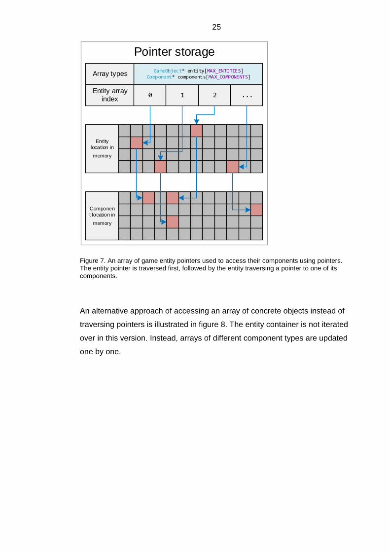
25
Pointer storage
Entity
location in
memory
Componen
t location in
memory
GameObject* entity[MAX_ENTITIES]Component* components[MAX_COMPONENTS]
Array types
Entity array index
0 1 2 ...
Figure 7. An array of game entity pointers used to access their components using pointers. The entity pointer is traversed first, followed by the entity traversing a pointer to one of its components.
An alternative approach of accessing an array of concrete objects instead of
traversing pointers is illustrated in figure 8. The entity container is not iterated
over in this version. Instead, arrays of different component types are updated
one by one.

26
Object storage
Render
component
location in
memory
Component array index
0 1 2 ...
Physics
component
location in
memory
PhysicsComponent physics[MAX_COMPONENTS]RenderComponent renderers[MAX_COMPONENTS]
Array types
Component array index
0 1 2 ...
Figure 8. Iterating over contiguous arrays of component objects for maximum cache coherency.
Nystrom (2014, 274, 285) lists Data Locality as a design pattern but states
that it is more of a mindset. Data arrangement and design choices while
programming the engine were often based on cache coherency. This resulted
in avoidance of polymorphism, inheritance and abstractions. Nystrom (2014)
comments on Data Locality: This kind of optimization is somewhere between a
black art and a rathole.
Despite the downsides of overly optimizing cache coherency, this kind of
design did not harm the flexibility of the engine dramatically in the engine
programmed for this thesis. This was due to the structures of the subsystems,
threading, and particularly the component model, which is discussed in
chapter 5.6.
In addition to loading data from the memory, there are other kinds of
optimizations related to caching, such as write-through cache tweaks for

27 storing data to RAM and instruction cache optimizations that are related to
how the actual program code is cached (Gregory 2014, 156-157; Nystrom
2014, 273). Instruction cache misses can be prevented by keeping
performance-critical loops small and avoiding function calls from innermost
loops (Gregory 2014, 159).
Another type of cache problem may occur when using multiple processors to
run different threads. If the data accessed by multiple threads is close together
in memory, the processors may end up transferring the cache line back and
forth, causing major performance issues. This kind of cache line sharing
without any of the actual data being shared is called false sharing. The
solution is to keep data accessed by a single thread close in memory, but far
from the data accessed by another thread. (Williams 2012; 238.)
5.5 Custom memory allocation
The default heap memory allocations are designed for general-purpose use
and are very slow operations in the context of game engines. Dynamic
memory allocation for is necessary in any game but should be avoided
whenever there is a better solution. Gregory (2014, 240) recommends the
following: Keep heap allocations to a minimum, and never allocate from the
heap within a tight loop. (Alexandrescu 2008, 78; Gregory 2014, 240; Nystrom
2014, 306.)
In addition to poor performance, the default dynamic allocations are likely to
cause memory fragmentation, where continuously allocated and freed
memory blocks cause the memory region to be populated with increasingly
varying sizes of allocated and unreserved areas. If the heap gets severely
fragmented, allocating large objects may fail, even though there would be
enough total free space to store it (figure 9). (Gregory 2014, 250-251; Nystrom
306.)
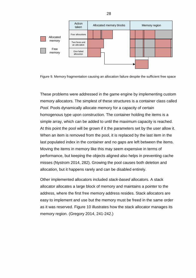
28
Allocated memory
Free memory
Memory region
Two frees and
an allocation
Four allocations
One failed
allocation
Action taken
Allocated memory blocks
Figure 9. Memory fragmentation causing an allocation failure despite the sufficient free space
These problems were addressed in the game engine by implementing custom
memory allocators. The simplest of these structures is a container class called
Pool. Pools dynamically allocate memory for a capacity of certain
homogenous type upon construction. The container holding the items is a
simple array, which can be added to until the maximum capacity is reached.
At this point the pool will be grown if it the parameters set by the user allow it.
When an item is removed from the pool, it is replaced by the last item in the
last populated index in the container and no gaps are left between the items.
Moving the items in memory like this may seem expensive in terms of
performance, but keeping the objects aligned also helps in preventing cache
misses (Nystrom 2014, 282). Growing the pool causes both deletion and
allocation, but it happens rarely and can be disabled entirely.
Other implemented allocators included stack-based allocators. A stack
allocator allocates a large block of memory and maintains a pointer to the
address, where the first free memory address resides. Stack allocators are
easy to implement and use but the memory must be freed in the same order
as it was reserved. Figure 10 illustrates how the stack allocator manages its
memory region. (Gregory 2014, 241-242.)
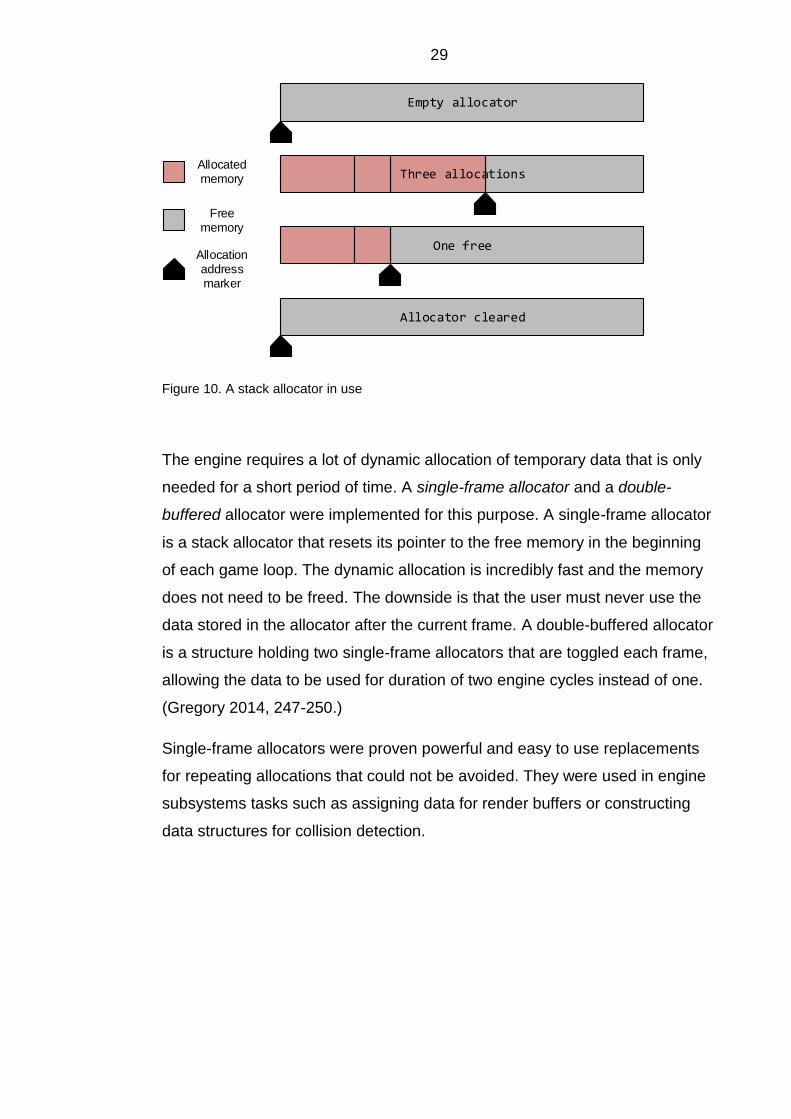
29
Empty allocator
Allocator cleared
Three allocations
One free
Allocated memory
Free memory
Allocation address marker
Figure 10. A stack allocator in use
The engine requires a lot of dynamic allocation of temporary data that is only
needed for a short period of time. A single-frame allocator and a double-
buffered allocator were implemented for this purpose. A single-frame allocator
is a stack allocator that resets its pointer to the free memory in the beginning
of each game loop. The dynamic allocation is incredibly fast and the memory
does not need to be freed. The downside is that the user must never use the
data stored in the allocator after the current frame. A double-buffered allocator
is a structure holding two single-frame allocators that are toggled each frame,
allowing the data to be used for duration of two engine cycles instead of one.
(Gregory 2014, 247-250.)
Single-frame allocators were proven powerful and easy to use replacements
for repeating allocations that could not be avoided. They were used in engine
subsystems tasks such as assigning data for render buffers or constructing
data structures for collision detection.

30 void Batch::UpdateColorBuffer1(const u32 bufferLength) { GLfloat* colBuf = new GLfloat[bufferLength]; // Populate array and send to GPU... delete[] colBuf; } void Batch::UpdateColorBuffer2(const u32 bufferLength) { GLfloat* colBuf = batchFrameAllocator.Allocate<GLfloat>(bufferLength); // Populate array and send to GPU... No deletion required } Listing 4. Comparison of array creation using the keywords new and delete (UpdateColorBuffer1-function) and reserving the array data using a single-frame allocator (UpdateColorBuffer2-function).
Listing 4 compares two variations of dynamic array creation. The first one is
using a simple array and dynamic allocation, while the second one applies a
single-frame allocator to avoid using the heap. No deletion of the data is
required while using the custom allocator, but it provides the functionality to
rewind the marker by the size of the data, freeing more memory to be used
during the current frame.
5.6 Game objects and the Component pattern
The largest module of the actual game programming layer in an engine is the
system representing the objects that exist in a game (Gregory 2014, 873). A
natural object-oriented way of classifying game objects is building a hierarchy,
where virtually all objects in the game world inherit from a base class, usually
named GameObject, Entity or Actor (figure 11).

31
GameObject
RenderedObject
Character
...
MovingObject ...
Vehicle Projectile ...
Player ...
Figure 11. A monolithic class hierarchy using inheritance to represent different objects in a game
While a basic inheritance hierarchy for game objects may work well for small
projects, it is prone to grow rapidly and become difficult to maintain. Deep
hierarchies require the users to know all of the base classes in addition to the
actual object they are working with. Added class features tend to be moved up
in the hierarchy to avoid code duplication: Objects may end up having
completely unused member variables and functions while the base class of all
game objects becomes large and unreadable. In addition, hierarchies tend to
be difficult to add completely new types of objects to. (Graham 2013, 155-159;
Gregory 2014, 877-880; Nystrom 2014; 213-216.)
To avoid the issues related to the inheritance-based game objects, the
Component pattern was applied to the engine. In this model, the behavior and
attributes of a game object are not defined by the class itself, but the
functionality other classes representing a set of properties (Gregory 2014,
881-882; Nystrom 215-217). Figure 12 illustrates how different objects can be
represented using components.

32
TransformComponent
RenderComponent
PhysicsComponent
AIComponent
GameObject
Figure 12. A game object composed of render, transform, physics and artificial intelligence components
The most common way to implement the Component pattern in a game
engine is to program a game object class that has pointers to its various
components. Components can be stored in contiguous arrays without much
effort, which allows them to perform extremely well in terms of cache
coherency. The components can either be hard-coded and left empty if the
functionality is not provided, or they can be represented as a dynamic list,
which offers more flexibility. (Gregory 2014, 881-886; Nystrom 2014, 217-231,
273-289.)
The engine programmed for this thesis uses even more flexible way in
representing game objects, the pure component model. Since the game object
class in a traditional component model is merely a hub connecting the
components together, it can be left out completely. In a pure component
model, there are only components bound together with a system like an
identifier or a circular linked list. This leads to game entities being lightweight
and their lifetime does not need to be managed: When the components are
deleted, the entity disappears. Figure 13 demonstrates how components using
a shared identifier can be used to represent a game object. (Gregory 2014,
886-887; Nystrom 2014, 228.)

33
”Game object 23"
RenderComponent
-objectID : i32 = 23
TransformComponent
-objectID : i32 = 23
AIComponent
-objectID : i32 = 23
PhysicsComponent
-objectID : i32 = 23
”Game object 45"
RenderComponent
-objectID : i32 = 45
TransformComponent
-objectID : i32 = 45
AIComponent
-objectID : i32 = 45
PhysicsComponent
-objectID : i32 = 45
Figure 13. Two game objects represented using pure component model: The game objects do not exist, but the components are connected by an identifier
5.6.1 Downsides of the pure component model
The problems with this approach are object creation and communication.
Since there is no object that can be used to create its components,
instantiation may be difficult. Object access can be done using the identifier
shared by the components but this may make the access slow if there are
numerous operations. One solution for component access and connections is
a circular linked list. (Graham 2013, 167; Gregory 2014, 886-887; Nystrom
289.)
Issues regarding the object creation were addressed in the engine by creating
template functions that automatically populate the component containers with
the required components. Component initialization can be further automatized
by creating temporary game object classes for creation purposes or using a
data-driven approach, where the objects are created by a script file or an
editor.
Performance problems related to the pure component model were solved by
using the index of the component in the array as its identifier. This introduced
another issue: The components representing a game entity must always be
located in the same indices of component arrays, thus adding, removing and
relocating the components became difficult. Some components also depend
on each other: Collider components and render components need to be paired
with a transform component for a position and collider components need to be
paired with a physics component. Enforcing these kinds of relationships may
be hard.

34 The most severe downside to the index-based model was that it became hard
to maintain the flexibility of the game objects having only the components they
need. Figure 14 shows, how instantiating four game objects causes memory
to be wasted: The second and the third object do not use physics components
and a gap is left in the array.
TransformComponent array
PhysicsComponent array
RenderComponent array
Id: 0
Id: 0
Id: 0
Id: 1
Id: 1
Id: 1
Id: 2
Id: 2
Id: 2
Id: 3
Id: 3
Id: 3
Required component
Unused and uninitialized component
Figure 14. Creation of game objects with different component requirements using pure component model can be wasteful. Out of the four created objects, only two utilize physics, but the component exists for all four object representations.
Since the components were linked to each other using their container index
and the engine needed to provide functionality for all the possible component
combinations for game entities, multiple component containers were used.
These containers were then grouped together based on components required
by game objects (figure 15).

35
Engine components
Container listing 1
TransformComponent array
PhysicsComponent array
AIComponent array
RenderComponent array
Container listing 3
RenderComponent array
TransformComponent array
Container listing 2
TransformComponent array
PhysicsComponent array
RenderComponent array
4
4
4
3
3
3
5
5
5
2
2
2
1
1
1
0
0
0
3
3
3
3
2
2
2
2
1
1
1
1
0
0
0
0
0
0
1
1
Figure 15. Component containers sorted by game object component requirements
The problems with the approach of container groups was the creation of the
containers themselves and accessing the correct container lists when
modifying game objects, since using an index directly was no longer valid.
Solutions to these issues are discussed in chapter 5.6.2.

36
5.6.2 Template metaprogramming and typelists
Template metaprogramming is a technique for creating source code at
compile time using templates (Alexandrescu 2008, 49-54). Some of the issues
discussed in chapter 5.6.1 can be resolved by using this method by creating
the required combinations of containers at compile time providing all the
possible component types as template parameters for the base of the
component system with no runtime overhead.
The different component container listings used by the engine component
model were created using typelists. Typelists are collections of different
objects and primitive types, consisting of nodes holding the type of the node
itself and the type of the next node. These kinds of lists do not have any
values, functionality or state and are only processed at compile time. An
empty type called NullType is created to represent a meaningless type and to
mark the end of typelist traversal. Figure 16 illustrates the structure of a
typelist containing the types of 8-bit and 32-bit signed integers and a C++
standard library string. (Alexandrescu 2008, 51-52.)
struct TypeList
typedef head
typedef tail
i8
struct TypeList
typedef head
typedef tail
i32
struct TypeList
typedef head
typedef tail
std::string
NullType
Figure 16. Typelist data structure visualization. The head node defines the type and the tail node defines the next typelist structure in the list.
Basic functionality was added to support the typelist structure use including
indexed access, type search, addition and removal. Due to the nature of

37 metaprogramming, all these functions are completely free to use during
runtime in terms of performance. (Alexandrescu 2008, 51-60.)
Listing 5 provides an example of a method of resolving the index of a specific
type in a typelist. The first template specialization defines the type as the
typelist at the tail node and subtracts from the index parameter recursively
until it is zero. At this point, the type is defined by the second specialization:
The result is the type at the head node. If the initial parameter for index is
higher than the length of the typelist, the code will not compile.
/** This specialization is recursed until the index is 0 template <typename Head, typename Tail, u32 index> struct TypeAt<TypeList<Head, Tail>, index> { typedef typename TypeAt<Tail, index - 1>::Result Result; };
/** When the recursed TypeList node index is zero, “traversing” ends and the type is defined as Result. */
template <typename Head, typename Tail> struct TypeAt<TypeList<Head, Tail>, 0> { typedef Head Result; }; Listing 5. The template specializations used to determine a type at a specific index of a typelist.
The power of typelists lies in their ability to create class hierarchies
automatically at compile time. The component container listing generation
works similarly to the Abstract Factory pattern, which provides a generic
interface for concrete factories that create objects of a specific type
(Alexandrescu 2008, 219-223). Typelists were used along with template
template parameters and template recursion to create a structure that was
named GeneratedClass in the engine. Listing 6 is an example of how a
component container list can be defined. The Holder type is a simple data
structure containing a single value. In this case, three Holder instances will be
created, each containing a container for a specific type of component.

38 typedef TL::GeneratedClass<TYPELIST_3 ( ComponentPool<TransformComponent>, ComponentPool<RenderComponent>, ComponentPool<PhysicsComponent> ), Holder> ComponentCollection; Listing 6. Definition of a component container list supporting transform, render and physics components. TYPELIST_3 is a helper macro providing easier initialization of a typelist.
Figure 17 demonstrates how the classes using GeneratedClass are formed
during compile time based on listing 6. The component container names are
simplified for clarity. An inheritance hierarchy containing typelists and concrete
variables is formed. Figure 18 illustrates the layout of the class created using
this kind of hierarchy.
ComponentCollection
GeneratedClass<TransformComponents, Holder>
Holder<TransformComponents> Holder<RenderComponents> Holder<PhysicsComponents>
GeneratedClass<RenderComponents, Holder>
GeneratedClass<PhysicsComponents, Holder>
GeneratedClass<TYPELIST_2(RenderComponents, PhysicsComponents), Holder>
GeneratedClass<TYPELIST_1(PhysicsComponents), Holder>
GeneratedClass<NullType, Holder>
Figure 17. Inheritance hierarchy for metaprogramming structure GeneratedClass. The ComponentCollection class inherits from every data structure visible in the figure.
ComponentCollection
-value : ComponentPool<TransformComponent>-value : ComponentPool<RenderComponent>-value : ComponentPool<PhysicsComponent>
Figure 18. GeneratedClass member variable listing representing the memory layout of the structure. The class has three component containers as its variables. The member variables have identical names.

39 Since all the variables in GeneratedClass share the same name, explicit cast
must be used to access them (Alexandrescu 2008, 67). Helper functions to
access these variables were programmed in the engine. For example, if a
seemingly vague GeneratedClass holds containers of transform and render
components, a specific component in this whole structure can be accessed by
providing the index and the type of the component requested (figure 19).
GetComponent<RenderComponent>(const u32 index)
ComponentCollection
-value : ComponentPool<TransformComponent>
-value : ComponentPool<RenderComponent>
static_cast<RenderComponent>(value[index])
static_cast<ComponentPool <RenderComponent> >(componentCollection).value
Figure 19. Accessing a component stored in a GeneratedClass structure.
Template metaprogramming can be used to create powerful structures with
low or no impact on performance. The downside is that the program code
tends to turn confusing quickly and maintaining it may be difficult if changes
are introduced.
The system programmed to automatize the container listing creation and
component access was not finished by the end of this thesis project. Deducing
the complex types of component container groups may be proven an
overwhelming task in the future when attempts are made to use the engine in
practice. Many of the methods related to this approach remain hard-coded at

40 this point in time, but template metaprogramming and other techniques can
certainly be leveraged to develop the solution further.
5.6.3 Property-centric design
Some game engines use a property-based object model instead of
implementing game entities as objects. In this design, the properties are the
actual objects in terms of program code, and the game objects act as the
variables. Property-centric architectures can be efficient in terms of memory
use and cache coherency but tend to have object communication related
problems. (Gregory 2014, 887-891.)
5.7 Engine messaging systems
Since the game engine does not implement actual game objects having direct
access to their components and the different subsystems work in separate
threads, care had to be taken in choosing safe and efficient object
communication methods. Direct data modification was unacceptable most of
the time, due to the asynchronous nature of the engine tasks.
5.7.1 Service Locator
A subsystem that needs to be accessed by different parts of the game engine
is often implemented by using a singleton. A singleton is a service that only
one instance can exist of. It is created only on request and can be initialized
during runtime unlike classes with static variables and functions. (Nystrom
2014, 73-76.)
The problem with the singleton pattern is that it is essentially a global variable.
Global variables needlessly make code harder to read, encourage tight
coupling and is hazardous when using multiple threads. If a function does not
access global state, it is easier for the compiler to optimize. In addition, the
way singletons are initialized and created can cause issues with custom
memory allocation. Due to these reasons, the singleton pattern was left out

41 from the engine completely at its current development phase. (Nystrom 2014,
77-80.)
Instead of using singletons or direct access to a subsystem, a pattern called
Service Locator was implemented in the engine. A service locator is a static
structure that holds links to the subsystems it provides access to. The system
to access has to be provided for the locator and can then be requested by any
class using it. This way the service locator nor the class accessing the service
do not have to know anything about the actual implementation of the
subsystem, providing reasonable decoupling (figure 20). (Nystrom 2014, 251-
253.)
Service::GetRenderer()...
Renderer implementationstatic Renderer* renderer
Service Locator
static Physics* physics
static Audio* audio
Figure 20. A Service Locator decouples a service from the system requesting it.
A service locator can be used for additional flexibility when accessing a class:
It can be provided with a null service that shares the interface of the actual
service but has no functionality. For example, an audio engine can be
replaced with a null service provided with a mix-in log class, causing calls to
play sound simply generate a log message instead. (Nystrom 2014, 256-258.)
This kind of subsystem access was used sparingly in the game engine and
the service locator implemented only offers access to a subsystem without
any additional functionality. The services provided by the locator were
renderer, physics, audio and the application window.
5.7.2 Event Queue
In the Event Queue pattern, a container is used to store generic requests or
commands to be received by a system that is interested in them. Using an

42 event queue effectively decouples the sender from the receiver of a message.
(Nystrom 2014, 233-237.)
Event objects were used to add flexibility by making the messages generic.
The type and arguments of an event were stored in the object, allowing certain
subsystems to interpret the events in the queue correctly. The event types
were stored as hashed strings to support a data-driven implementation of
events. The event arguments were stored in a structure containing a union of
different types and a type identifier. The implementation is presented in listing
7. The event type and the arguments can be coupled using key-value pairs for
even further flexibility and automation. (Gregory 2014, 935-939.)
struct Event { u32 hashedString; EventArgument arg; }; struct EventArgument { enum EArgType { TYPE_INT, TYPE_FLOAT, TYPE_BOOL }; union UArgData { i32 argInt32; f32 argF32; bool argBool; }; EArgType type; };
Listing 7. The data structures containing the event and argument objects
In addition to decoupling the message passing, events offer benefits such as
extending them by using inheritance hierarchies and event forwarding
(Gregory 2014, 936). The latter can be used to pass an event to another
object without knowing anything about its actual functionality. For example, a
game object representing a house may receive an event called evacuate. The
house object does not have the functionality to respond to the event, but can
pass it forward to possible character entities inside. Events can also be
handled at a time suitable to the user and prioritized if necessary (Gregory
2014, 944-945).

43
5.8 Thread safety
Assigning individual parallel processing threads for systems such as physics
and rendering is an effective approach in a game engine. The downside of this
method are the difficulties in thread communication. While decoupled and
well-designed component model helps with this problem, it does not account
for all the risks involved. (Graham 2013, 177; Gregory 2014, 370; Nystrom
2014, 214; Williams 2012, 6-8.)
5.8.1 Common multithreading issues
Direct multithreaded object modification causes problems like race conditions,
where accessed data may become invalid because different threads are
altering it simultaneously. Data can be locked temporarily to avoid this by
using a synchronization primitive called a mutex. However, careless use of
mutexes can lower performance and cause a condition called deadlock, where
two or more threads are holding a mutex lock and waiting for the other threads
to release their locks. This causes the threads to stall (figure 21). Race
conditions and deadlocks are the most common problems related to
threading. (Williams 2012, 34-48, 180-184.)
Thread 1 Thread 2
Lock object 1
Unlock object 1
Access object 2
Lock object 2
Unlock object 2
Access object 1
Deadlock
Figure 21. Deadlock caused by a conflict of two threads attempting to access objects locked by the other thread.

44
5.8.2 Concurrent containers
A concurrent pool structure was used in the engine to access different
component objects from separate threads. It protects data modification of the
components by utilizing mutexes. The downside to this is the frequent locking
and unlocking of the data structure which may hinder performance. In
addition, accessing the pool from a function that is also using a lock may
cause a deadlock, so the user must be cautious when accessing this data
structure (Williams 2012, 49).
A concurrent queue was implemented for the Event Queue pattern and other
asynchronous messaging. The implementation uses the queue structure
provided by the C++ standard library as its base. The interface for this
structure provides functions for adding an item into the queue and retrieving
them from it, as well as checking whether or not the queue is empty. The
retrieval can either be used by attempting to get an item from the queue and
continuing regardless of the result, or stalling the thread by waiting until there
is something to retrieve from the queue.
Another concurrent data structure implemented was a thread-safe ring buffer.
It is a fixed size array that starts rewriting the first indices when it is full. To
keep the buffer data from being overwritten, values are always read from the
oldest added item. The read and write indices are stored in the structure
(figure 22). (Nystrom 2014, 241-244.) The weakness of this structure is that
new items added in the queue may be discarded if the array is full. It offers the
same functionality as the concurrent queue but is faster, simpler and requires
no dynamic memory allocation. Ring buffers were used for events such as
playing sounds, since the loss of an event message is not crucial in this
context.

45
Reserved index
Free index
Write index
Read index
4 items added
2 items read
10 items added5 items read
3 items added10 items read
Figure 22. Visualization of a ring buffer
It is important to note that the concurrent queue structures cannot utilize
functions like top or front, which are used in single-thread queues and stacks
to retrieve the value of the first item in the container. These kinds of functions
cause data races if multiple threads use them at the same time. This is
demonstrated in figure 23: Two threads read the same value from a stack and
proceed to remove the first item, unintentionally removing a different value
and causing the same value to be processed twice.

46
Thread A Thread B
Lock stack and call top(), unlock
Process value
Lock stack and call pop(), unlock
Lock stack and call top(), unlock
Process value
Lock stack and call pop(), unlock
Stack values are 0, 1, 2, 3
Both threads process 3,
2 has been discarded
Thread B is returned 3
Thread A pops 3
Thread B pops 2
Stack values are 0, 1
Thread A is returned 3
Figure 23. A data race caused by the function top of a stack structure. Locking the structure
during the call to top does not qualify for a thread-safe action.
Simple variables and single values or flags were too lightweight to store and
access using these containers. Because of this, concurrent items such as the
flags keeping the thread loops running or subsystem state enumerations were
implemented by using atomic types. These types are always accessed and
modified using atomic operations, which can only be observed if they are only
partially done. This means that data races cannot occur with simple atomic
variables. (Williams 2012, 103-107.) Atomic operations can be a hundred
times slower than using simple variable, but they are accessed rarely in the
engine code (Williams 2012, 199). Relaxed memory ordering was typically
used for these kinds of variables, which offers good atomic performance but
ignores all ordering and synchronization of the variable modification and
access, making it a poor choice for structures that must operate in a
predictable manner (Williams 2012, 123-128).

47
6 RENDERING SYSTEM
The job of the rendering engine is to draw the game state on the screen in
real-time. The goals for the renderer implemented in this engine were drawing
primitive two-dimensional shapes, lines and points as well as textured quads
with high performance using OpenGL while maintaining cross-platform
support.
While the rendering system is simple, the aim was to make it easily
extendable. Due to the amount of third party libraries used and different
rendering hardware across the common platforms, the rendering subsystem
introduces a variety of exceptions based on the operating system.
6.1 Application window
The window is the first system the engine launches. It initializes the SDL
library which uses functionality specific to the operating system to create a
new window for OpenGL to use for rendering.
The window class operates in the main thread along with the input events,
since SDL requires this for the platform-specific systems (SDL Wiki, 2016).
When tested during engine development, Windows, Linux and Android ran
without problems with windowing and input being in a separate thread. Mac
OS X received input but did not provide an application window.
6.2 Renderer initialization
The actual rendering system immediately begins a thread of its own, waiting
for the application window to be initialized. Once the window is available,
OpenGL context is created. The context is a structure maintaining the state of
the OpenGL instance. The importance of render thread encapsulation is
crucial, since the context cannot be accessed or modified by another thread.
(OpenGL Wiki, 2015.)

48
6.3 Texture loading
Texture files are loaded into OpenGL memory by using basic SDL
functionality. Swapping textures continuously causes performance problems
and creating efficient texture atlases by hand is impractical, so an automated
texture packing system was implemented (Shreiner et al. 2013, 309). The
engine only creates maximum sized textures, fitting all the loaded images into
them. When a texture is full, a new one is created automatically.
Texture atlas 1 Texture atlas 2
(9 textures stored) (2 textures stored)
Figure 24. Texture packing in texture atlases
Figure 24 presents an example of texture placement in texture atlases. New
atlases are created as the existing ones are filled. A texture resource class
was implemented in the engine to keep track of texture size and position
inside the atlas. This information is used by the render components to resolve
texture coordinates.
6.4 Scene rendering
The renderer stores a container of objects that represent different shader
programs. Three major programs were implemented in the engine to render
fonts, colored shapes, and textured quads. The shader program objects have
unique initialization and rendering functionality and they handle required
OpenGL calls automatically, creating, maintaining and updating the memory
buffers used by the graphics processing unit. Figure 25 illustrates how the
shader program and shader behavior objects are stored.

49
Renderer
ShaderProgram
TextureBehavior
PrimitiveBehavior
FontBehavior
ShaderBehavior
1
1
...
1
1..*
Figure 25. Shader storage and inheritance hierarchy
The different shader behaviors were implemented by using inheritance to
keep the basic functionality same for all and to allow the shader collection to
be extended with ease. The goal was to free the engine user from accessing
low-level OpenGL systems and focusing on game programming instead.
When the render loop is running, the subsystem iterates over all the active
shader programs and draws the objects using them (Figure 26).

50
Initialize and load
shaders
Render()
Texture shader
program
Primitive shader
program
Font shader
program
…
Uninitialize and
shut down
Figure 26. Overview of the rendering subsystem thread
The renderer gets the data it requires from transform and render components
as well as new shader program objects created by the user. As the game
engine is running, the rendering subsystem does not need to be accessed at
all. The scene is modified by accessing the render components from another
thread using provided functions. The rendering engine reacts to the
component modifications, updating the essential data.
6.4.1 Batching and optimization
Since draw commands are expensive to call, it is recommended to store as
much as the rendering data into one buffer as possible (ARM Information
Center, 2013). This was done by sorting objects sharing similar properties into
groups called batches. The sorting criteria include shader programs, texture
atlases and usage of other properties such as color. Figure 27 demonstrates
how the OpenGL API calls add overhead and causes the processing take a
longer time for the same amount of data.

51
Figure 27. OpenGL API call overhead for draw calls. The amount of data processed is the same, but the performance is lower in the upper image. (ARM Information Center, 2013.)
The batch objects are owned by the shader programs. Similar to the shader
program objects being updated by the main rendering engine, the batches are
iterated over and updated by the shader program objects. Each batch
represents one draw call.
Batching is automatic and requires no actions from the user: When a
component is created or modified, the subsystem finds a proper batch for it
using functions provided by the shader program object. If a suitable batch is
not found, it is created. The process is illustrated in figure 28.
Component added or
modified
Attach component to
shader program
Resolve component
rendering properties
Remove from a
possible existing batch
Add component to a
batch or create one
Update batch buffer
data
Figure 28. The process of attaching a render component to a batch
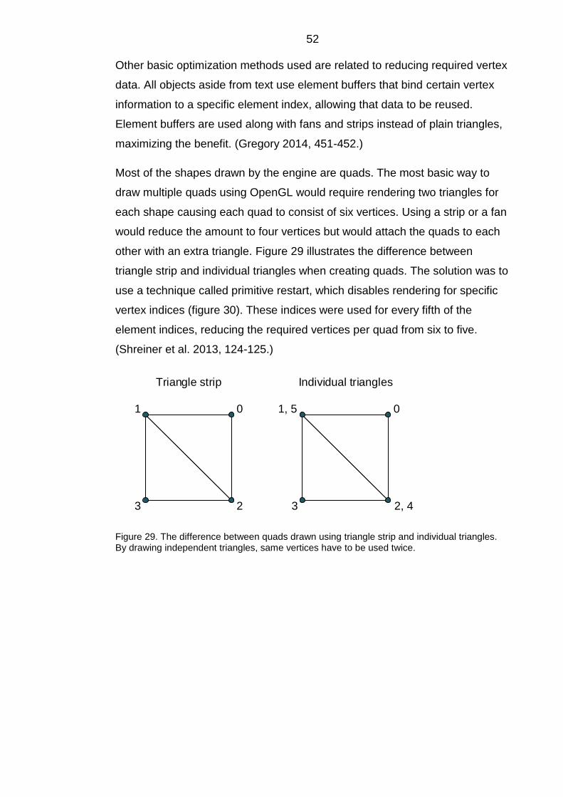
52 Other basic optimization methods used are related to reducing required vertex
data. All objects aside from text use element buffers that bind certain vertex
information to a specific element index, allowing that data to be reused.
Element buffers are used along with fans and strips instead of plain triangles,
maximizing the benefit. (Gregory 2014, 451-452.)
Most of the shapes drawn by the engine are quads. The most basic way to
draw multiple quads using OpenGL would require rendering two triangles for
each shape causing each quad to consist of six vertices. Using a strip or a fan
would reduce the amount to four vertices but would attach the quads to each
other with an extra triangle. Figure 29 illustrates the difference between
triangle strip and individual triangles when creating quads. The solution was to
use a technique called primitive restart, which disables rendering for specific
vertex indices (figure 30). These indices were used for every fifth of the
element indices, reducing the required vertices per quad from six to five.
(Shreiner et al. 2013, 124-125.)
Triangle strip
0
2
1
3
0
2, 4
1, 5
3
Individual triangles
Figure 29. The difference between quads drawn using triangle strip and individual triangles. By drawing independent triangles, same vertices have to be used twice.

53
Triangle strip,
no primitive restart,
8 element indices
Triangle strip,
primitive restart,
9 element indices0
2
1
3
4
6
5
7
0
2
1
3
5
7
6
8
(4 is primitive restart index)
Figure 30. Primitive restart. The primitive restart index causes the vertex to be discarded, splitting the triangle strip.
The shader program responsible for drawing the primitive shapes such as
circles uses geometry shaders for maximum optimization. Geometry shaders
can be used to draw completely shapes in the shader code using the graphics
processing unit directly (figure 31). This allows the engine to pass simple point
types into the shader program to draw various primitives. While the textured
quads require five vertices to draw the element, the primitives using geometry
shaders only require one. (Shreiner et al. 2013, 510-511.)

54
A simple point is passed to
the geometry shader
0
Geometry shader utilizes
triangle strip to turn the
point into a filled circle
0
Figure 31. Using a geometry shader used to draw a circle
Geometry shaders only support one primitive type at a time and it cannot be
changed by using an attribute. This means that drawing filled shapes requires
a different shader program than drawing outlined ones. (Shreiner et al. 2013,
512-514.) Two geometry shaders are used in the engine, one drawing line
strips and one drawing triangle strips.
6.4.2 Flyweight pattern and instanced rendering
Data buffers required for rendering are prone to cause needless data
duplication in both RAM and graphics processing unit memory. Shaders
usually hold a range of variables per vertex and a lot of this data is shared
between many elements. The idea of the Flyweight pattern is to minimize this
kind of needless doubling by using a shared base entity for multiple objects.
The principle is to split the objects into two sets of data, one being the shared,
unchanged data and the other being the data that can differ for each object.
(Nystrom, 2014, 33-37.)
One of the clearest examples of the pattern can be seen by using instanced
rendering, which is a feature implemented by OpenGL and the hardware
(Nystrom, 2014, 36). The engine is capable of creating multiple instance
groups with their own sets of rules.

55
Texture coordinates
Vertex positions
Color
Transform data
Individual
component
representation
Individual
component
representation
Shared base buffer
...
Transform buffer:
0...n occurrences
in memory
Base buffer:
1 occurrence in
memory
Regular rendering Instanced rendering
Vertex position buffer:
0...n occurrences in memory
...
Texture position buffer:
0...n occurrences in memory
...
Color buffer:
0...n occurrences in memory
.. .
Figure 32. Impact of instanced rendering on GPU memory usage. In instancing, individual objects are represented by a simpler set of data, since they share most of their properties using the base buffer. Transform buffer is not necessarily uploaded to the GPU in non-instanced rendering but is still used for position calculations.

56 Figure 32 demonstrates the difference in memory usage between regular and
instanced rendering. For example, a tile map could be rendered with each tile
sharing data for vertex positions, color and texture coordinates. These
variables would only appear once in the base buffer. The locations of the tiles
could then be determined by the transformation matrices of the objects,
provided by the transform components.
6.5 Platform restrictions
While GLEW handles a lot of problems caused by different OpenGL versions,
different platforms and hardware still introduce problems when implementing a
rendering engine. Major issues arise when porting to mobile platforms. The
OpenGL implementation for portable systems is called OpenGL ES and it
offers the same basic functionality as regular OpenGL. The latest versions
include most of the features but are only supported by a small percentage of
devices (Dashboards | Android Developers 2016; iOS Device Compatibility
Reference 2016).
The Android and iOS renderer implementations of the engine target OpenGL
ES 2.0 which is available for most mobile devices (Dashboards | Android
Developers 2016; iOS Device Compatibility Reference 2016). However,
features like primitive restart, instanced rendering and geometry shaders are
not available (OpenGL ES - The Standard for Embedded Accelerated 3D
Graphics 2016). This leads to more data duplication and increased memory
use as well as worse support for very large amount of objects rendered at the
same time.
6.6 Shortcomings of the rendering subsystem
The rendering engine lacks some basic functionality such as determining the
draw order and the ability to toggle visibility for individual elements. Dynamic
draw order could be implemented utilizing by batch-sorting the objects based
on their order but this would cause the number of batches to grow greatly if
used excessively. One possible solution for visibility toggle is making it a
property and creating a visibility buffer.

57 Another problem is related to ordering elements by their textures: The only
way to do this is to assure that the images are loaded into memory in the
correct order. Even this might not help: If assets appear in different scenes,
the ordering becomes harder. Texture arrangement matters, because one of
the criteria in batch sorting is the texture atlas index. Inefficient ordering may
cause the system to generate batches that could have been merged with
another group if the assets would have existed in the same texture atlas.
7 PHYSICS ENGINE
The physics subsystem simulates forces applied to game objects, moving and
rotating them accordingly. The forces affecting the objects may be
accumulated by the physics simulation subsystem in form forces such as
gravity, buoyancy or collision impacts, or they can be invoked by a specific
function from a game logic thread. An overview of the physics subsystem is
presented in figure 33.
WorldStep()
Add/Update
force generators
Update physics
components
Broad-phase
collision tests
Narrow-phase
collision tests
Resolve
contacts
Figure 33. Physics main loop overview

58
7.1 Attaching physics to game objects
Allowing an object to simulate physics in the engine was a trivial task by
combining the Game Loop, Update Method and Component patterns
described in chapters 5.2, 5.3 and 5.6. The engine associates physics
components and colliders with game entities and updates them inside the
physics engine main loop.
The physics component is used to calculate the position and orientation
changes caused by various forces based on either a fixed update interval or a
variable frame time measurement (Millington 2010, 55). Mass and angular
mass variables introduce a problem in physics calculations: Some objects
cannot be moved and an infinite mass must be used for them, but there is no
way to represent infinity in C++ calculations. The solution is to make the
components use inverse mass instead. This makes it impossible for the
component to have no mass, but infinite mass can be simulated by merely
setting the value to zero. (Millington 2010, 51-52.)
7.2 Force generators
A physics engine needs a way to apply general forces such as wind currents,
buoyancy, gravity or explosion blast force to game objects. This was
implemented in the engine by using an abstract ForceGenerator class.
Engine users can inherit the base class and use polymorphism to easily add
custom forces to be used by a game. Another class called ForceHandler was
created to manage the generators and to keep track of the force generators
and the physics components they affect (figure 34). (Millington 2010, 80-87.)

59
ForceGenerator
GravityGenerator WindGenerator ...
PhysicsComponent
ComponentGeneratorPair1
1
1
1
ForceHandler
1
0..*
Figure 34. The relationships of physics components, forces and the physics engine
7.3 Collision handling
Collisions are typically handled in two ways in game engines: Collision
detection or contact generation. Both determine which collider pairs are
interpenetrating and return penetration depth and the point of collision. The
difference is that contact generation provides additional data, such as
additional penetration points or broad contact areas and direction of the
collision. (Millington 2010, 294.) Simple contact generation was implemented
in the engine to resolve contacts of two-dimensional collider pairs.
Collision detection can be split into phases to optimize performance for high
collider counts. A broad-phase collision test is ran first, calculating potential
contacts using simplified versions of the colliders and fast algorithms. The
contact list is then iterated over using a more accurate and expensive way to
resolve the actual contacts. This is called narrow-phase collision detection.
These methods are demonstrated in figure 35. Some physics engines use
additional tests like a mid-phase between broad and fine collision detection.
(Gregory 2014, 677; Millington 2010, 254.)

60
Potential contact
Resolved contact
Broad-phase collision test Narrow-phase collision test
Figure 35. Comparison between broad-phase and narrow-phase collision tests
Having multiple phases in the collision detection system means that the
objects need to be represented by approximate bounding volumes in addition
to their actual colliders. These are colliders that are efficient to work with and
cover the whole area containing the possibly more complex narrow-phase
collider or a whole set of colliders (figure 36). The best performing collider for
a volume is the circle collider, since the only the center points and the radii are
needed for resolving. (Gregory 2014, 661-666; Millington 2010, 257.)
Complex shape
Bounding volume
Figure 36. Bounding volume used to simplify collision detection for a complex shape during broad-phase collision test

61
7.3.1 Broad-phase collision tests and Spatial Partition
To implement a broad-phase collision detection phase, adopting an
optimization pattern called Spatial Partition is required. Its aim is to organize
objects in a space by their positions and allows the user to check whether they
exist near or at a specific location. This information can be used to form
potential contact pairs to be used by the more accurate narrow-phase collision
detection test. (Millington 2010, 256-266; Nystrom 2014, 321-332.)
Various algorithms and techniques exist to choose from for a broad-phase
spatial partitioning solution. A structure called quadtree was implemented in
the engine programmed for this thesis. The construction of a quadtree begins
as a single area containing the objects to be checked for collisions. The
objects are added into the tree one by one.
When a limit of objects in the area is reached, it is split into four smaller areas
and the objects in the tree are fit in them. This continues recursively until all
the objects are handled. The colliders inside the same area or on the borders
of the area can then be added to the set of potential collisions. The areas
evaluated by a quadtree can be seen in figure 37. The three-dimensional
equivalent of a quadtree is an octree, which works the same way, but splits a
three-dimensional area into eight rectangular prisms instead of four
rectangles. (Millington 2010 281-282; Nystrom 2014, 334-335.)

62
Figure 37. A screenshot of a quadtree reducing the count of potential contacts. An object occupying an area by itself will not be tested for any further collisions. The profiling build of the engine was used to render the data structure itself.
Another technique was partially implemented, called bounding volume
hierarchy (BVH). In this approach, the bounding volumes of objects close to
each other form pairs that generate another, larger area covering them both.
These volumes are then used to form pairs if necessary. The algorithm
continues until one volume covers all of the other volumes. BVH tree utilized
to generate potential contacts is illustrated in figure 38. (Millington 2010, 257-
274.)

63
2
13
4
65
Colliders in the game area
2 1
543 6
Tree structure generated by BVH
Figure 38. Bounding volume hierarchy structure
The quadtree approach used for the engine was not without its share of
problems. The most notable issue with the approach was the varying size of
objects. The tree is extremely accurate and fast using points, but colliders with
different volume sizes may span multiple areas.
Two solutions were tested to solve this issue: Including the collider in multiple
areas and placing the collider in the parent of the nodes. The first approach
provided accurate results and there was no need to keep track of the parent
nodes: Only the smallest leaf nodes had to be considered. However, the
amount of nodes grew high especially using large objects and the traversal
was slow. The second approach offered notably faster tree population and
less nodes, leading to faster traversal, but the list of potential contacts grew: A
collider in the center of the quadtree had to be evaluated with all other
colliders. Overall, placing colliders in the parent nodes was faster in the tests.

64
7.3.2 Narrow-phase collision detection
Once the broad-phase collision test is over, the physics engine has a list of
potential contact pairs it can work with. The most complex forms of the object
colliders are checked for interpenetration. If the objects penetrate each other,
collision contact data is calculated. (Millington 2010, 294-298.)
A class called ContactGenerator was implemented in the engine to calculate
the contact data for a collision. It is used to generate Contact objects, which
contain data such as object penetration depth, collision points and normals,
bounce and friction as well as references to the colliding objects. The
ContactGenerator has the ability to resolve contacts between different shaped
colliders. (Millington 2010, 298-330.)
The last step of the contact generation is applying the collision effects to the
physics components. This was done by implementing a class called
CollisionResolver, which takes a container of Contact objects as a parameter
and applies impulse forces to the physics components, causing them to
separate and rotate.
Interpenetration was solved by moving the components based on the contact
normals before applying the forces. When using CollisionResolver to apply the
contact generation system results, a maximum amount of iterations is set.
Interpenetration corrections may cause new collisions and it may take a long
time or even forever until the algorithm ends. This makes limitless iteration
prone to physics engine stalls, unexpected slowdown or even stack overflow.
(Millington 2010, 132, 335-384.) The full contact generation pipeline is
illustrated in figure 39.
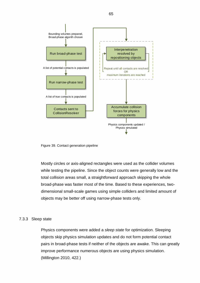
65
Run broad-phase test
Run narrow-phase test
Bounding volumes prepared,Broad-phase algorith chosen
A list of potential contacts is populated
Contacts sent to
CollisionResolver
A list of true contacts is populated
Interpenetration
resolved by
repositioning objects
Repeat until all contacts are resolvedOR
maximum iterations are reached
Accumulate collision
forces for physics
components
Physics components updated /Physics simulated
Figure 39. Contact generation pipeline
Mostly circles or axis-aligned rectangles were used as the collider volumes
while testing the pipeline. Since the object counts were generally low and the
total collision areas small, a straightforward approach skipping the whole
broad-phase was faster most of the time. Based to these experiences, two-
dimensional small-scale games using simple colliders and limited amount of
objects may be better off using narrow-phase tests only.
7.3.3 Sleep state
Physics components were added a sleep state for optimization. Sleeping
objects skip physics simulation updates and do not form potential contact
pairs in broad-phase tests if neither of the objects are awake. This can greatly
improve performance numerous objects are using physics simulation.
(Millington 2010, 422.)

66 The physics engine holds threshold values for rotational and linear motion.
When a physics component is updated, it calculates its motion and compares
it to the threshold values. If the motion values are below the threshold, the
component is put to sleep mode. The component is awoken on collision
impulses and other force accumulation events. (Millington 2010, 425-429.)
Component awake
Component sleeping
Figure 40. Sleep state in physics simulation. Stationary objects are omitted from calculations.
Figure 40 illustrates a possible effect of the sleep state optimization in a game
level. Physics is simulated for components affected by gravity, collision, or
impacts. Stationary components that have been left alone have been set to
sleep state and their physics calculations are not processed.
8 OTHER SYSTEMS AND UTILITIES
Various helper classes and smaller systems were implemented in the engine
to be extended further and to make common tasks easier. This chapter
describes some of the functionality of the engine that is not directly associated

67 with the major subsystems. Unimplemented features planned for upcoming
development are also discussed.
8.1 Input
The SDL library was used to receive input from the user. It works in the main
thread due to SDL restrictions (SDL Wiki, 2016). However, experimenting with
threading indicated that specializing the code to allow a separate input thread
may work on some platforms. This would improve the responsivity of user
input, since the thread could focus on only processing the hardware input.
Another considered solution was stripping the main thread of all functionality
aside from the program code related to the application window and input
tasks. This would allow the game logic to be processed in its own dedicated
thread.
The state of a controller using digital buttons was read by using a single
integer variable. This makes it easy to read the whole state of the controller
and to query specific button presses in a fairly abstract way. (Gregory 2014,
385-386.)
8-bit integer value
0 1 2 3 4 5 6 7
Figure 41. State of a game controller represented as a single 8-bit integer
Figure 41 demonstrates an example of how the state of a digital input
controller can be read. Each bit in the variable represents a button. The state

68 of an individual button can be read masking the input variable using a bitmask
utilizing the bitwise AND-operator (Gregory 2014, 386).
8.2 Utility classes and functions
The aim of the utility category is to make the use of the engine both easier and
less prone to errors. The utilities implemented in the engine provide commonly
used functions for tasks such as string hashing, timers and array
manipulation. More concrete structures include containers, error handling and
debug systems as well as data access classes.
8.2.1 Handles
Handles are used to represent objects using an identifier, such as an integer.
This adds a level of indirection to object access and can protect from errors
such as accessing a null pointer. Figure 42 illustrates the idea of the handle
system: A handle table is created, which is essentially a container of memory
addresses. Handles are simply indices of this table and can thus be used to
access the actual objects. (Gregory 2014, 911-912.)
Objects in
memory
Handle table
0 1 2 3 4
Object 1
Object 2
nullptr
Object 3
...
Handle to Object 3
Handle
-handleID : i32 = 4
Figure 42. A handle table linking handle indices to memory addresses
69 Handles were used in the engine to provide a means for memory relocation.
Memory defragmentation methods and structures such as the Pool class
described in chapter 5.5 can cause pointer invalidation. This was not a major
problem for most of the items placed in pools in the engine, since container
indices were used to refer to them most of the time.
An example of the application crashing due to pointer invalidation was
experienced with the temporary debug text labels used in the engine. Since
there was no easily accessible container for labels, subsystems in different
threads used a raw label pointer to modify the texts. The memory address of
the pointer was then sent to the font shader program to be populated with a
new label object. The label objects existed inside a pool container owned by
the font shader program. When the container would be full, it would be grown
to fit more labels in. Since resizing the container required creating a new array
for the items, their memory addresses were updated and the pointers used by
the subsystem threads would access whatever random data the old memory
address now contained. Handles were used to fix the issue.
Figure 43 demonstrates how the pointer invalidation issue can be resolved
using pointer relocation using the handle structures. An array needs to be
deleted replaced with a new, dynamically allocated array in order to resize it.
Raw pointers used to access the array are no longer valid, whereas a handle
table equipped with a relocation function can maintain the validity of handles
easily.

70
Objects in
memory
Object array 0 1 2 3
Pointer array 0 1 2 3
Objects in
memory
Object array 0 1 2 3
Pointer array 0 1 2 3
4 5 6 7
Random data
Objects in
memory
Object array 0 1 2 3
Handle table 0 1 2 3
Objects in
memory
Object array 0 1 2 3
Handle table 0 1 2 3
4 5 6 7
Handles 0 1 2 3
Handles 0 1 2 3
Relocate(arr, len);
Object array size doubledPointers invalidated: undefined behavior
Object array size doubledHandle table relocates pointers
Figure 43. Comparison of pointer access and handle table supporting relocation when resizing a basic array
8.2.2 Random number generation
Generating pseudo-random values is a necessity in games. Standard random
number generation functions like C library’s rand-function may use algorithms
that produce low quality values and are slow. For these reasons, a custom
random number generator was implemented as a utility class for the engine.
(Graham 2013, 85; Gregory 2014, 227-228.)
A random number generator called xorshift+ was used in the engine to provide
high quality sequences of random values with good performance. The C++11
implementation of the pseudo-random number generator called Mersenne
twister was used to generate even higher quality random numbers and to
allow different types of distributions, such as normal distribution. Xorshift+ was
chosen as the default generator to be used by the engine utility, since it has

71 better performance than Mersenne twister. (Gregoire et al. 2011, 582-590;
Gregory 2014, 228; xorshift* / xorshift+ generators and the PRNG shootout,
2009.)
8.3 Unimplemented engine features
Due to the broad nature of the subject, many of the fundamental features had
to be omitted from the engine programmed for this thesis. Some of these
features and ways to implement them are briefly discussed in this chapter.
8.3.1 Resource manager
As the number of multimedia assets required by a game increases, so does
the need for a resource management system. Its tasks include reading asset
files from the disk, loading them into the game, maintaining asset identifiers
and access and freeing resources when needed. Resource managers can
support features like automatically loading the required assets for a scene and
streaming, where assets are loaded seamlessly in the background while the
game scene is running. (Gregory 2014, 297-338.)
Many game engines utilize a resource database, which contains all the assets
used by a game sorted by types, hierarchies and other properties. This
database can be used to access the resources in a flexible and easy way.
(Gregory 2014, 310-319.) The engine programmed for the thesis currently
loads the assets using hard-coded asset names.
8.3.2 Audio engine
Sound is often an overlooked part of a game. Even though a base for simple
audio playback functionality was implemented in this engine, a good audio
system provides many more features. These include located sound sources,
environmental models to describe the properties and the geometry of a space,
echoes, Doppler effect and more. Dialogue is another broad area tightly
coupled with the audio engine. (Gregory 2014, 743-844.)

72
8.3.3 User interface
A minor form of a visible user interface in the engine provided for this thesis,
but its main purpose is debugging. Elements like menus or buttons were
omitted from the current engine version. A proper user interface can be
considered another major subsystem in the engine and an additional thread
can be dedicated to it, since it should typically be separated from the actual
game logic and driven by events. Optimizing the usage of font assets and
resizing elements is another major topic related to user interfaces. (McShaffry
2013, 269-281.)
8.3.4 Networking
Network and multiplayer features are common in games today. An engine
supporting this must implement support for client-server relationships or peer-
to-peer architecture. Various interfaces and classes can be programmed for
sockets and network packets to help application communication. Network
behavior can even be implemented as a component attached to a game
entity. (Gregory 2014, 375-379; McShaffry 2013, 643-692.)
9 CONCLUSIONS
The objectives set for the thesis were met well overall. A working, extendable
game engine with core features was created and will be further refined in the
future. The most important subsystems, the rendering and physics engines,
were successfully decoupled and improving them should be a straightforward
task.
Working on the engine demonstrated that many of the techniques and
patterns may be hard to adapt to a certain kind of engine, and appear better in
theory than in practice: Applying a technique can affect other parts of the
software and cause additional issues. However, some approaches resolved
multiple problems, such as the component model coupled with cache line
optimization.

73 Programming the engine was a valuable learning experience. Experimenting
with different structures, techniques, operating systems and other tools
provided an excellent view on game engine functionality in general and helped
perceive program code entireties better. Especially the graphics processing
unit programming with OpenGL helped develop understanding of the low-level
rendering systems and introduced new game programming problems to be
resolved.
Hopefully, this thesis can be utilized as learning material for game
programmers unaware of the subjects examined. Additionally, the rendering
subsystem and the component model discussed in this thesis introduce ideas
that are not directly using any techniques found in the used source material.
No concluding solutions were provided for the issues related to these topics,
but the suggested ideas can hopefully be improved, partially applied and
provoke thoughts on the subject.
As suspected in the beginning of the project, keeping with the timeline proved
difficult. Lack of experience in OpenGL programming caused the rendering
system implementation to take thrice the time reserved for it. The most severe
impact of this was on input and sound systems, which were simplified
radically. The tight schedule also lead to rushed programming, which
jeopardized the initial goal of providing readable code. Parts of the engine in
its current form resemble the Lava Flow AntiPattern, where unused or
forgotten low-quality program code is left to clutter the codebase, because
removing it might cause functioning structures to fall apart (Brown, Malveau,
McCormick III & Mowbray, 1998, 49-53).
The broad nature of the subject also hindered another goal set for the project:
Creating a game built on the engine. An extremely simple demo game was
programmed, but it fails to showcase most of the features provided by the
engine. The original schedule included various game-related techniques and
design patterns related to game object state, artificial intelligence and input.
Data-driven subjects such as editors and bytecode were also omitted from this
thesis.
When programming a custom game engine, proper planning and patience is
essential. It calls for the ability to picture the entirety of the engine codebase
and its requirements. Building a game engine provides valuable insight of

74 game structures but is a task not to be taken lightly. Choosing from the vast
array of currently available complete game engines is a good choice for most
developers, especially when implementing complex, three-dimensional
games.

75
REFERENCES
Alexandrescu, A. 2008. Modern C++ Design: Generic Programming and Design Patterns Applied. Indiana: Addison-Wesley.
Brown, W., Malveau R., McCormick III, H. & Mowbray, T. 1998. AntiPatterns: Refactoring Software, Architectures, and Projects in Crisis. New York: John Wiley & Sons.
ARM Information Center. 2013. Available: http://infocenter.arm.com/help/index.jsp?topic=/com.arm.doc.dui0555c/CHDFCCII.html [Accessed: 20 April 2016].
CppCheck – A tool for static C/C++ code analysis. 2015. Available: http://cppcheck.sourceforge.net/ [Accessed: 19 October 2015].
Dashboards | Android Developers. 2016. Available: http://developer.android.com/intl/zh-cn/about/dashboards/index.html [Accessed: 25 April 2016].
Gregoire, M., Solter, N. & Kleper, S. 2011. Professional C++, second edition. Indianapolis: John Wiley & Sons.
Gregory, J. 2014. Game Engine Architecture, second edition. USA: CRC Press, Boca Raton.
iOS Device Compatibility Reference. 2016. Available: https://developer.apple.com/library/ios/documentation/DeviceInformation/Reference/iOSDeviceCompatibility/OpenGLESPlatforms/OpenGLESPlatforms.html [Accessed: 25 April 2016].
McDonald, J., Gledreich, R. & Lantinga, S. 2013. Porting Source to Linux: Valve's Lessons Learned (Presented by NVIDIA). GDC Vault. Available: http://www.gdcvault.com/play/1017850/, https://developer.nvidia.com/sites/default/files/akamai/gamedev/docs/Porting%20Source%20to%20Linux.pdf [Accessed: 19 November 2015].
McShaffry, M. & Graham, D. 2013. Game Coding Complete, fourth edition. Boston: Cengage Learning PTR.
Millington, I. 2010. Game Physics Development, second edition. Burlington: Morgan Kaufmann.
Nystrom, R. 2014. Game Programming Patterns. USA: Genever Benning.
OpenGL Context. 2015. OpenGL Wiki. Available: https://www.opengl.org/wiki/OpenGL_Context [Accessed: 5 February 2016].
OpenGL ES - The Standard for Embedded Accelerated 3D Graphics. 2016. Available: https://www.khronos.org/opengles [Accessed: 25 April 2016].
OpenGL Mathematics. 2016. Available: http://glm.g-truc.net/0.9.7/index.html [Accessed: 25 April 2016].
SDL Wiki. 2016. Available: https://wiki.libsdl.org/ [Accessed: 5 February 2016].

76 Shreiner, D., Sellers, G., Kessenich, J. & Licea-Kane, B. 2013. OpenGL Programming Guide, eighth edition. Michigan: Addison-Wesley Professional.
Van Heesch, D. 2015. Doxygen: Main Page. Available: http://www.stack.nl/~dimitri/doxygen/index.html [Accessed: 20 October 2015].
Williams, A. 2012. C++ Concurrency in Action, Practical Multithreading. New York: Manning Publications.
xorshift* / xorshift+ generators and the PRNG shootout. 2009. Available:
http://xorshift.di.unimi.it [Accessed: 23 April 2016].

77
FIGURES
Figure 1. The directory structure applied for the development of this engine
Figure 2. Screenshots of the engine log
Figure 3. The impact of the alignment on structure size in memory. The width of the int variable represents four bytes and the width of the char variable represent one byte.
Figure 4. A rough overview of the structure of the engine programmed for this thesis
Figure 5. Separating rendering from the main logic loop. The whole figure represents a main game loop updating the whole engine in a single thread. Logic inside the dashed rectangle requires to be updated at fixed interval.
Figure 6. Thread update setup example. Different subsystem threads can be specialized to have unique update rules.
Figure 7. An array of game entity pointers used to access their components using pointers. The entity pointer is traversed first, followed by the entity traversing a pointer to one of its components.
Figure 8. Iterating over contiguous arrays of component objects for maximum cache coherency.
Figure 9. Memory fragmentation causing an allocation failure despite the sufficient free space
Figure 10. A stack allocator in use
Figure 11. A monolithic class hierarchy using inheritance to represent different objects in a game
Figure 12. A game object composed of render, transform, physics and artificial intelligence components
Figure 13. Two game objects represented using pure component model: The game objects do not exist, but the components are connected by an identifier
Figure 14. Creation of game objects with different component requirements using pure component model can be wasteful. Out of the four created objects, only two utilize physics, but the component exists for all four object representations.
Figure 15. Component containers sorted by game object component requirements
Figure 16. Typelist data structure visualization. The head node defines the type and the tail node defines the next typelist structure in the list.
Figure 17. Inheritance hierarchy for metaprogramming structure GeneratedClass. The ComponentCollection class inherits from every data structure visible in the figure.

78 Figure 18. GeneratedClass member variable listing representing the memory layout of the structure. The class has three component containers as its variables. The member variables have identical names.
Figure 19. Accessing a component stored in a GeneratedClass structure.
Figure 20. A Service Locator decouples a service from the system requesting it.
Figure 21. Deadlock caused by a conflict of two threads attempting to access objects locked by the other thread.
Figure 22. Visualization of a ring buffer
Figure 23. A data race caused by the function top of a stack structure. Locking the structure during the call to top does not qualify for a thread-safe action.
Figure 24. Texture packing in texture atlases
Figure 25. Shader storage and inheritance hierarchy
Figure 26. Overview of the rendering subsystem thread
Figure 27. OpenGL API call overhead for draw calls. The amount of data processed is the same, but the performance is lower in the upper image. ARM Information Center. 2013. Available: http://infocenter.arm.com/help/index.jsp?topic=/com.arm.doc.dui0555c/CHDFCCII.html [Accessed: 20 April 2016].
Figure 28. The process of attaching a render component to a batch
Figure 29. The difference between quads drawn using triangle strip and individual triangles. By drawing independent triangles, same vertices have to be used twice.
Figure 30. Primitive restart. The primitive restart index causes the vertex to be discarded, splitting the triangle strip.
Figure 31. Using a geometry shader used to draw a circle
Figure 32. Impact of instanced rendering on GPU memory usage. In instancing, individual objects are represented by a simpler set of data, since they share most of their properties using the base buffer. Transform buffer is not necessarily uploaded to the GPU in non-instanced rendering but is still used for position calculations.
Figure 33. Physics main loop overview
Figure 34. The relationships of physics components, forces and the physics engine
Figure 35. Comparison between broad-phase and narrow-phase collision tests
Figure 36. Bounding volume used to simplify collision detection for a complex shape during broad-phase collision test
Figure 37. A screenshot of a quadtree reducing the count of potential contacts. An object occupying an area by itself will not be tested for any

79 further collisions. The profiling build of the engine was used to render the data structure itself.
Figure 38. Bounding volume hierarchy structure
Figure 39. Contact generation pipeline
Figure 40. Sleep state in physics simulation. Stationary objects are omitted from calculations.
Figure 41 State of a game controller represented as a single 8-bit integer
Figure 42. A handle table linking handle indices to memory addresses
Figure 43. Comparison of pointer access and handle table supporting relocation when resizing a basic array
Appendix 1 Doxygen documentation
Comment-based Doxygen documentation for the program code comprising the game engine programmed for the thesis. The documentation is available as a compressed file at https://www.theseus.fi