Embed Size (px)
Citation preview
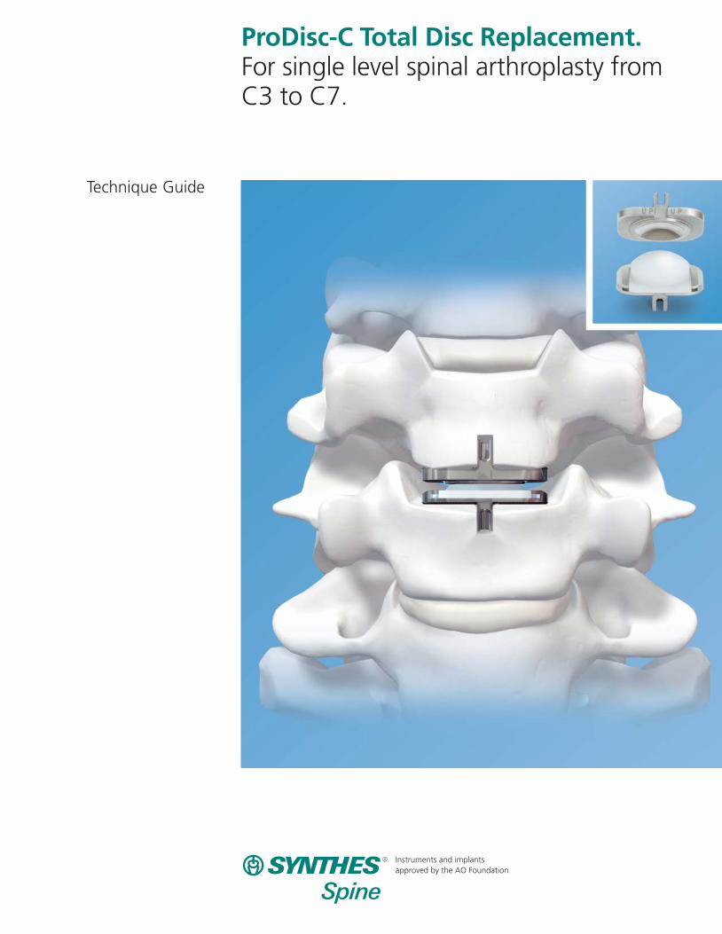
ProDisc-C Total Disc Replacement. For single level spinal arthroplasty fromC3 to C7.
Technique Guide
Instruments and implants approved by the AO Foundation


Introduction
Surgical Technique
Product Information
Table of Contents
ProDisc-C Total Disc Replacement 2
Features and Potential Benefits 3
Indications and Contraindications 4
Patient Exclusion Recommendations 5
Patient Positioning 7
Exposure 8
Marking the Midline 8
Discectomy, Decompression and Remobilization 9
Implantation 13
1. Trial 13
2. Keel Preparation 15
3. Implant Insertion 19
Postoperative Care 22
Implant Removal 22
Implants 23
Instruments 24
Set List 28
Image intensifier control
Synthes Spine

ProDisc-C Total Disc Replacement
The ProDisc-C Total Disc Replacement (Figure 1) is intendedto replace a diseased and/or degenerated intervertebral discof the cervical spine in patients with symptomatic cervicaldisc disease (SCDD). The ProDisc-C Total Disc Replacementprocedure is intended to significantly reduce pain by allowing for the removal of the diseased disc while restoringdisc height and providing the potential for motion at the affected vertebral segment.
The ProDisc-C Total Disc Replacement is a modular implantconsisting of two CoCrMo (cobalt chromium molybdenum)endplates and one UHMWPE (ultra-high molecular weightpolyethylene) inlay. The inferior CoCrMo alloy endplate has a midline keel that is anchored into the endplate of the inferior vertebral body. The UHMWPE insert is preassembledsnap-locked into a tray detail in the inferior CoCrMo alloy endplate and provides the inferior convex bearing surface.The superior CoCrMo alloy endplate has a midline keel thatanchors to the superior vertebral body and has a highly polished concave bearing surface that articulates with theconvex UHMWPE spherical dome. Immediate anchoring ofProDisc-C Total Disc Replacement to the vertebral bodies is achieved through a midline keel that is oriented anterior-posterior on the surface of each of the two endplates. In addition, the bone-contacting surfaces of the inferior and superior endplates, as well as both keels, are titanium plasmaspray coated to allow for long-term fixation (Figure 2).
The plasma sprayed titanium surface texture also provides a high coefficient of friction to aid in immediate implant fixation. CoCrMo alloy was used in ProDisc-C Total Disc Replacement for its superior strength, proven biocompatibility,superior abrasion resistance, and superior wear characteristicswhen coupled with UHMWPE.
ProDisc-C Total Disc Replacement is labeled MR Conditional,where it has been demonstrated to pose no known hazardsin a specified MR enviroment with specified conditions ofuse. Please refer to page 6 for further information.
2 Synthes Spine ProDisc-C Total Disc Replacement
Figure 1
Figure 2

Features and Potential Benefits
Ball and socket design– Allows for the potential for motion in the treated segment
– Provides a fixed center of rotation
– Resists shear forces
Device design range of motion (as measured throughin vitro testing)– 20° flexion/extension (17.5° for 5 mm large, large deep,
extra large, and extra large deep implants)
– 20° lateral bending (17.5° for 5 mm large, large deep, extra large, and extra large deep implants)
– Unconstrained in axial rotation
Anatomical sizing– Six (6) endplate footprints (medium, medium deep, large,
large deep, extra large, extra large deep)
– 5 mm, 6 mm and 7 mm heights
– 18 implant configurations
Synthes Spine 3
Figure 3
Stable fixation– Patented central keels (oriented anterior-posterior) provide
secure primary fixation
– Titanium porous coating aids in long-term fixation
Dimensions—endplates
Implant Size AP Lateral Disc heights(mm) (mm) (mm)
Medium 12 15 5, 6, 7
Medium Deep 14 15 5, 6, 7
Large 14 17 5, 6, 7
Large Deep 16 17 5, 6, 7
Extra Large 16 19 5, 6, 7
Extra Large Deep 18 19 5, 6, 7
XLD
LD
MD
M
Dep
th (m
m)
XL
L
1816
14
12
1917
15
Width (mm)
5 mm6 mm 7 mm
Figure 4
Figure 5
4 Synthes Spine ProDisc-C Total Disc Replacement
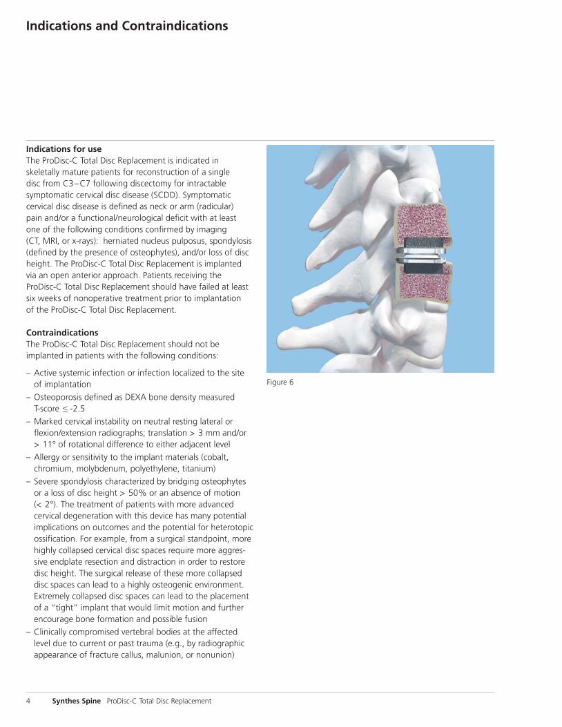
Indications for useThe ProDisc-C Total Disc Replacement is indicated in skeletally mature patients for reconstruction of a single disc from C3–C7 following discectomy for intractable symptomatic cervical disc disease (SCDD). Symptomatic cervical disc disease is defined as neck or arm (radicular) pain and/or a functional/neurological deficit with at least one of the following conditions confirmed by imaging (CT, MRI, or x-rays): herniated nucleus pulposus, spondylosis(defined by the presence of osteophytes), and/or loss of discheight. The ProDisc-C Total Disc Replacement is implantedvia an open anterior approach. Patients receiving theProDisc-C Total Disc Replacement should have failed at leastsix weeks of nonoperative treatment prior to implantation of the ProDisc-C Total Disc Replacement.
ContraindicationsThe ProDisc-C Total Disc Replacement should not be implanted in patients with the following conditions:
– Active systemic infection or infection localized to the siteof implantation
– Osteoporosis defined as DEXA bone density measured T-score ≤ -2.5
– Marked cervical instability on neutral resting lateral or flexion/extension radiographs; translation > 3 mm and/or > 11° of rotational difference to either adjacent level
– Allergy or sensitivity to the implant materials (cobalt,chromium, molybdenum, polyethylene, titanium)
– Severe spondylosis characterized by bridging osteophytesor a loss of disc height > 50% or an absence of motion (< 2°). The treatment of patients with more advanced cervical degeneration with this device has many potentialimplications on outcomes and the potential for heterotopicossification. For example, from a surgical standpoint, morehighly collapsed cervical disc spaces require more aggres-sive endplate resection and distraction in order to restoredisc height. The surgical release of these more collapseddisc spaces can lead to a highly osteogenic environment.Extremely collapsed disc spaces can lead to the placementof a “tight” implant that would limit motion and furtherencourage bone formation and possible fusion
– Clinically compromised vertebral bodies at the affectedlevel due to current or past trauma (e.g., by radiographicappearance of fracture callus, malunion, or nonunion)
Indications and Contraindications
Figure 6
The safety and effectiveness of this device has not been es-tablished in patients with the following conditions:
– not skeletally mature
– patients under the age of 22 or over the age of 60
– more than one vertebral level with SCDD
– prior fusion surgery at an adjacent vertebral level
– prior surgery at the level to be treated
– patients with progressive symptoms and signs of spinalcord/nerve root compression with less than six weeks ofconservative treatment
– facet joint disease or degeneration at the level to betreated
– neck or arm pain of unknown etiology
– Paget’s disease, osteomalacia, or other metabolic bone disease
– pregnancy
– taking medications known to potentially interfere withbone/soft tissue healing (e.g., steroids)
– rheumatoid arthritis or other autoimmune disease
– severe diabetes mellitus requiring daily insulin treatment
– systemic disease including AIDS, HIV, and hepatitis
– active malignancy
In order to minimize the risk of periprosthetic vertebral fractures, surgeons must consider all comorbidities, past andpresent medications, previous treatments, etc. A screeningquestionnaire for osteoporosis, SCORE (Simple CalculatedOsteoporosis Risk Estimation), may be used to screen patientsto determine if a DEXA bone mineral density measurement is necessary. If DEXA is performed, the patient should be excluded from receiving the device (per the contraindicationslisted above) if the DEXA bone density measured T-score is ≤ -2.5, as the patient may be osteoporotic.
Use aseptic technique when removing the ProDisc-C TotalDisc Replacement implant from the innermost packaging.
Use care when handling the ProDisc-C Total Disc Replace-ment implant to ensure that it does not come in contact with objects that could damage the implant. Exercise care to ensure that implantation instruments do not contact the highly polished articulating surfaces of the endplates. Damaged implants are no longer functionally reliable.
To prevent unnecessary damage to the bearing surfaces, ensure that blood or other debris is not trapped within the device.
Synthes Spine 5
Patient exclusion recommendationsPatient selection is one of the most important factors contributing to the outcome of the total disc replacementprocedure. The following may affect clinical outcomes:
– The patient’s occupation or activity level
– A condition of senility, mental illness, alcoholism, or drug abuse
– Degenerative diseases that may be so advanced at thetime of implantation that they limit the expected life of the implant
WarningsCorrect placement of the device is essential to optimal performance. Use of the ProDisc-C Total Disc Replacementshould only be undertaken after the surgeon has becomethoroughly knowledgeable about spinal anatomy and biome-chanics, has had experience with anterior cervical spinal surgeries, and has had hands-on training in the use of thisspecific device. A lack of adequate experience and/or trainingmay lead to a higher incidence of adverse events, includingneurological complications.
There were no patients in the pivotal study who were lessthan 22 years of age. The safety and effectiveness of this device has not been studied in the pediatric or adolescentage group (< 22 years old).
Due to the proximity of vascular and neurological structuresto the implantation site, there are risks of serious or fatalhemorrhage and risks of neurological damage with the useof this device.
PrecautionsPatient selection is extremely important. In selecting patientsfor a total disc replacement the following factors can be ofimportance to the success of the procedure: the patient’s occupation or activity level, a condition of senility, mental illness, alcoholism, or drug abuse. In addition, certain degenerative diseases may be so advanced at the time of implantation that the expected useful life of the device issubstantially decreased.
Furthermore, correct selection of the appropriate implant sizeis extremely important to assure the placement and functionof the device. Please refer to this technique guide for step-by-step instructions on the required surgical technique, including determining the correct implant size.
Patient Exclusion Recommendations

6 Synthes Spine ProDisc-C Total Disc Replacement
ProDisc-C Total Disc Replacement implant should not be used with components or instruments of spinal systems fromother manufacturers. See the surgical technique guide forstep-by-step instructions.
Surgical implants must never be reused or reimplanted. Even though the device appears undamaged, it may havesmall defects and internal stress patterns that may lead toearly breakage.
Patients should be instructed in postoperative care procedures and should be advised of the importance of adhering to these procedures for successful treatment with the device, including the avoidance of heavy lifting,repetitive bending, and prolonged or strenuous activity initially and for a period of weeks to months depending on the individual patient’s progress and the stability andfunctioning of the implant.
Preoperative considerationsPerform a thorough review of patient history, physical examand imaging studies to identify possible contraindications to total disc replacement and to identify the appropriate symptomatic level. Upon reviewing all pertinent information,determine whether a bone density scan is appropriate.
MRI informationSynthes ProDisc-C implants are labeled MR Conditional according to the terminology specified in ASTM F 2503-05,Standard Practice for Marketing Medical Devices and OtherItems for Safety in the Magnetic Resonance Enviroment.
Nonclinical testing of the ProDisc-C demonstrated that theimplant is MR Conditional. A patient with a ProDisc-C implantmay be scanned safely under the following conditions:– Static magnetic field of 1.5 Tesla and 3.0 Tesla at Normal
Operating Mode or First Level Controlled Mode
– Highest spatial gradient magnetic field of 900 Gauss /cm or less
– Maximum MR system reported whole body averaged specific absorption rate (SAR) of 2 W/kg for the Normal Operating Mode and 4 W/kg for the First Level ControlledMode for 15 minutes of scanning.
Patient Exclusion Recommendations continued
Note: In nonclinical testing, a Synthes ProDisc-C implant oflargest geometrical volume and mass was tested for heatingand results showed a maximum observed heating of 1.1°Cfor 1.5 T and a maximum observable heating of 1.9°C for3.0 T with a machine reported whole body averaged SAR of2 W/kg as assessed by calorimetry.
Patients may be safely scanned in the MRI chamber at theabove conditions. Under such conditions, the maximal expected temperature rise is less than 2°C. To minimize heating, the scan time should be as short as possible and the SAR as low as possible. Temperature rise values obtained were based upon a scan time of 15 minutes.
The above field conditions tested in a 1.5 T and a 3.0 TPhilips Achieva (Philips Healthcare, Software release 2.6.3SP4) MR scanner should be compared with those of theuser’s MR system in order to determine if the item can safelybe brought into the user’s MR environment. Synthes MR Conditional ProDisc-C implants may have the potential tocause artifact in the diagnostic imaging.
Artifact InformationMR image quality may be compromised if the area of interestis in the same area or relatively close to the position of theProDisc-C implant and it may be necessary to optimize MR imaging parameters in order to compensate for the presence of the implant.
A representative implant has been evaluated in the MRIchamber and worst case artifact information is provided below. Overall, artifacts created by ProDisc-C implants maypresent issues if the MR imaging area of interest is in or nearthe area where the implant is located.- For FFE sequence: Scan duration: 3 min, TR 100 ms,
TE 15 ms, flip angle 15°, worst case artifact will extend approximately 3.5 cm from the implant
- For SE sequence: Scan duration: 4 min, TR 500 ms, TE 20ms, flip angle 70°, worstcase artifact will extend approxi-mately 2.5 cm from the implant
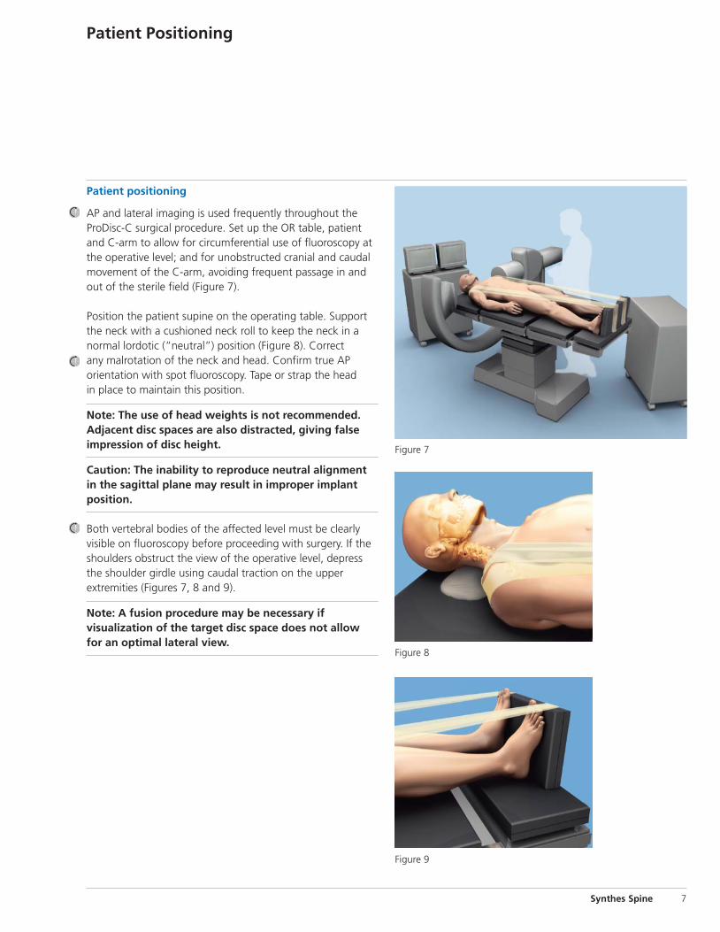
Figure 7
Figure 8
Figure 9
Synthes Spine 7
Patient positioning
AP and lateral imaging is used frequently throughout theProDisc-C surgical procedure. Set up the OR table, patientand C-arm to allow for circumferential use of fluoroscopy atthe operative level; and for unobstructed cranial and caudalmovement of the C-arm, avoiding frequent passage in andout of the sterile field (Figure 7).
Position the patient supine on the operating table. Supportthe neck with a cushioned neck roll to keep the neck in anormal lordotic (“neutral”) position (Figure 8). Correct any malrotation of the neck and head. Confirm true AP orientation with spot fluoroscopy. Tape or strap the head in place to maintain this position.
Note: The use of head weights is not recommended.Adjacent disc spaces are also distracted, giving falseimpression of disc height.
Caution: The inability to reproduce neutral alignmentin the sagittal plane may result in improper implant position.
Both vertebral bodies of the affected level must be clearlyvisible on fluoroscopy before proceeding with surgery. If theshoulders obstruct the view of the operative level, depressthe shoulder girdle using caudal traction on the upper extremities (Figures 7, 8 and 9).
Note: A fusion procedure may be necessary if visualization of the target disc space does not allow for an optimal lateral view.
Patient Positioning
ExposureExpose the operative level via a standard transverse approachto the anterior cervical spine. Verify the operative level withfluoroscopy.
Note: The presence of anatomical abnormalities and/or deformities, such as the presence of scoliosis, kyphosisor abnormal segmentation, may reduce the ability toensure proper placement of the instrumentation and/orprosthesis and may require that a fusion procedure beperformed.
8 Synthes Spine ProDisc-C Total Disc Replacement
Exposure
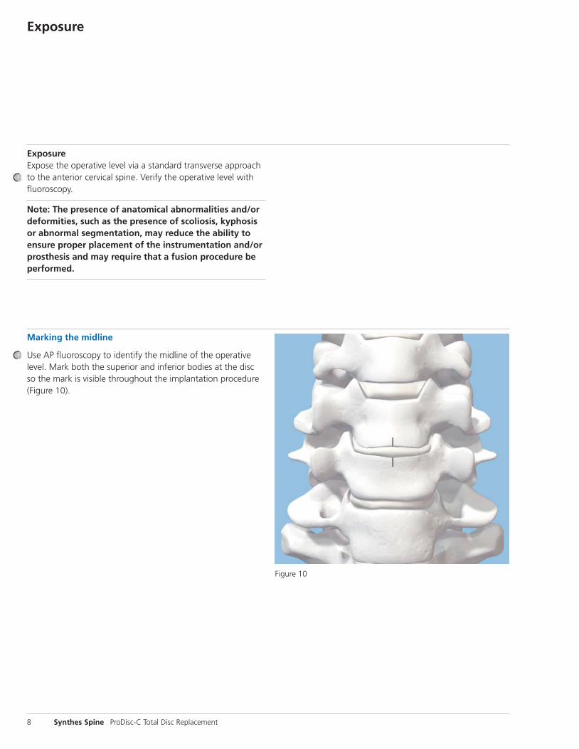
Marking the midline
Use AP fluoroscopy to identify the midline of the operativelevel. Mark both the superior and inferior bodies at the disc so the mark is visible throughout the implantation procedure(Figure 10).
Figure 10
Discectomy, Decompression, and Remobilization
Instruments
03.820.100 Awl, 12 mm
03.820.101 Self-Retaining Screwdriver
03.820.110 Retainer Nut
03.820.111 Vertebral Body Retainer
03.820.112 Vertebral Distractor
Standard Screws
03.820.102– Retainer Screws, 3.5 mm 03.820.105 x 12 mm, 14 mm, 16 mm, and 18 mm
Rescue Screws
03.820.106– Retainer Screws, 4.5 mm 03.820.109 x 13 mm, 15 mm, 17 mm, and 19 mm
Note: Performing a complete and meticulous discectomy,decompression, and remobilization of the disc space iscritical to the success of the surgery. The surgeon mustremobilize the diseased segment and restore the discheight prior to implantation of the ProDisc-C Total DiscReplacement.
Thorough disc space preparation is best performed with controlled, parallel distraction of the operative level. Distraction should be obtained using the vertebral distractorand maintained with the specially-designed screw-and-retainer device. Technique for use is:
1.Insert retainer screws in the vertebral bodies;
2.Attach the retainer to the screws, apply initial predistraction to the disc space and perform preliminary discectomy;
3.Insert the vertebral distractor and apply parallel distraction; and
4.Complete the discectomy, decompression and remobilization of the space.
Synthes Spine 9
Discectomy, Decompression, and Remobilization continued
10 Synthes Spine ProDisc-C Total Disc Replacement
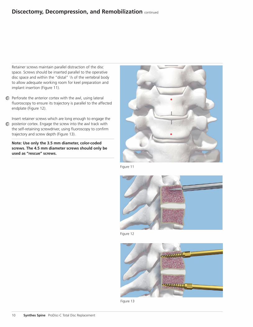
Retainer screws maintain parallel distraction of the discspace. Screws should be inserted parallel to the operativedisc space and within the “distal” 1/3 of the vertebral body to allow adequate working room for keel preparation andimplant insertion (Figure 11).
Perforate the anterior cortex with the awl, using lateral fluoroscopy to ensure its trajectory is parallel to the affectedendplate (Figure 12).
Insert retainer screws which are long enough to engage theposterior cortex. Engage the screw into the awl track with the self-retaining screwdriver, using fluoroscopy to confirmtrajectory and screw depth (Figure 13).
Note: Use only the 3.5 mm diameter, color-codedscrews. The 4.5 mm diameter screws should only beused as “rescue” screws.
Figure 11
Figure 12
Figure 13
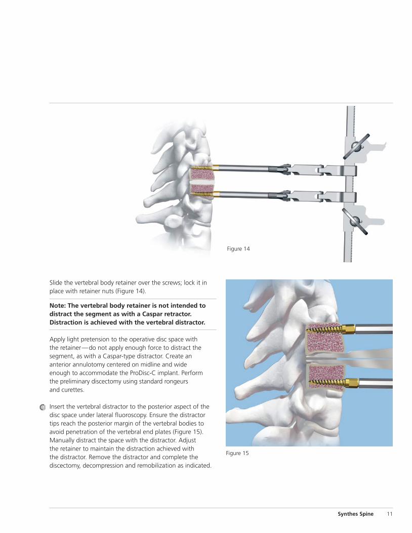
Figure 14
Slide the vertebral body retainer over the screws; lock it inplace with retainer nuts (Figure 14).
Note: The vertebral body retainer is not intended todistract the segment as with a Caspar retractor. Distraction is achieved with the vertebral distractor.
Apply light pretension to the operative disc space with the retainer—do not apply enough force to distract the segment, as with a Caspar-type distractor. Create an anterior annulotomy centered on midline and wide enough to accommodate the ProDisc-C implant. Perform the preliminary discectomy using standard rongeurs and curettes.
Insert the vertebral distractor to the posterior aspect of thedisc space under lateral fluoroscopy. Ensure the distractortips reach the posterior margin of the vertebral bodies toavoid penetration of the vertebral end plates (Figure 15).Manually distract the space with the distractor. Adjust the retainer to maintain the distraction achieved with the distractor. Remove the distractor and complete the discectomy, decompression and remobilization as indicated.
Figure 15
Synthes Spine 11
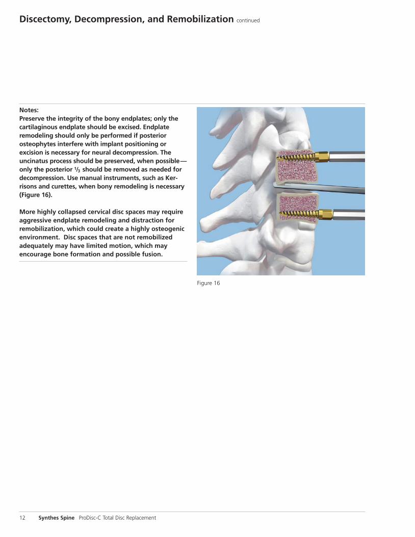
Notes:Preserve the integrity of the bony endplates; only thecartilaginous endplate should be excised. Endplate remodeling should only be performed if posterior osteophytes interfere with implant positioning or excision is necessary for neural decompression. The uncinatus process should be preserved, when possible—only the posterior 1/3 should be removed as needed fordecompression. Use manual instruments, such as Ker-risons and curettes, when bony remodeling is necessary(Figure 16).
More highly collapsed cervical disc spaces may require aggressive endplate remodeling and distraction for remobilization, which could create a highly osteogenicenvironment. Disc spaces that are not remobilized adequately may have limited motion, which may encourage bone formation and possible fusion.
Figure 16
12 Synthes Spine ProDisc-C Total Disc Replacement
Discectomy, Decompression, and Remobilization continued
1Trial
Instruments
03.820.000 Handle, for Trial Implants
03.820.025– Trial Implants (medium, medium deep, large, 03.820.077 large deep, extra large, extra large deep)
03.820.113 Slotted Mallet
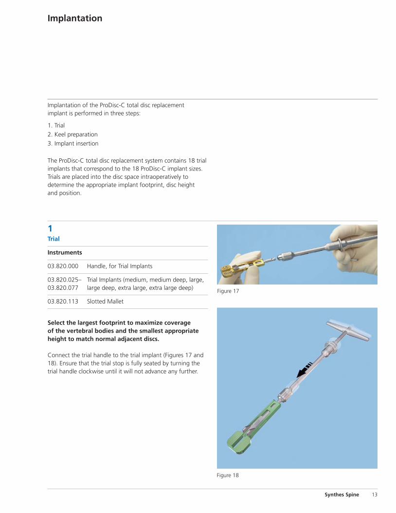
Select the largest footprint to maximize coverage of the vertebral bodies and the smallest appropriateheight to match normal adjacent discs.
Connect the trial handle to the trial implant (Figures 17 and18). Ensure that the trial stop is fully seated by turning thetrial handle clockwise until it will not advance any further.
Implantation
Implantation of the ProDisc-C total disc replacement implant is performed in three steps:
1. Trial
2. Keel preparation
3. Implant insertion
The ProDisc-C total disc replacement system contains 18 trialimplants that correspond to the 18 ProDisc-C implant sizes.Trials are placed into the disc space intraoperatively to determine the appropriate implant footprint, disc height and position.
Synthes Spine 13
Figure 18
Figure 17
14 Synthes Spine ProDisc-C Total Disc Replacement
Figure 19
Figure 20
Figure 21 Figure 22
1Trial continued
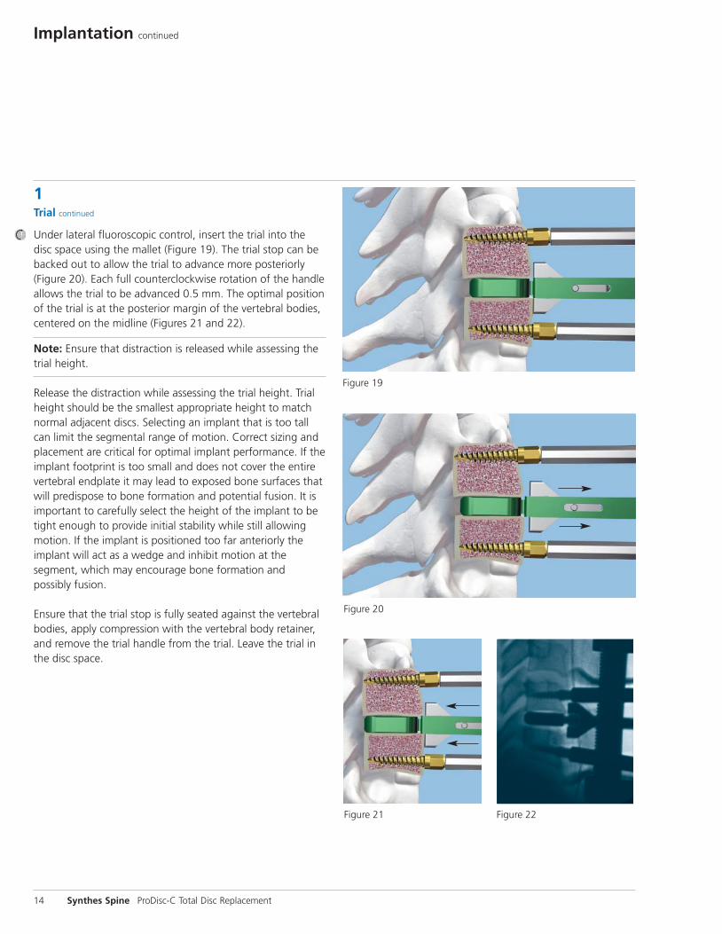
Under lateral fluoroscopic control, insert the trial into thedisc space using the mallet (Figure 19). The trial stop can bebacked out to allow the trial to advance more posteriorly(Figure 20). Each full counterclockwise rotation of the handleallows the trial to be advanced 0.5 mm. The optimal positionof the trial is at the posterior margin of the vertebral bodies,centered on the midline (Figures 21 and 22).
Note: Ensure that distraction is released while assessing thetrial height.
Release the distraction while assessing the trial height. Trialheight should be the smallest appropriate height to matchnormal adjacent discs. Selecting an implant that is too tallcan limit the segmental range of motion. Correct sizing andplacement are critical for optimal implant performance. If the implant footprint is too small and does not cover the entirevertebral endplate it may lead to exposed bone surfaces thatwill predispose to bone formation and potential fusion. It isimportant to carefully select the height of the implant to betight enough to provide initial stability while still allowing motion. If the implant is positioned too far anteriorly the implant will act as a wedge and inhibit motion at the segment, which may encourage bone formation and possibly fusion.
Ensure that the trial stop is fully seated against the vertebralbodies, apply compression with the vertebral body retainer,and remove the trial handle from the trial. Leave the trial inthe disc space.
Implantation continued
Synthes Spine 15
2Keel preparationThere are two surgical options for keel preparation of thevertebral bodies: milling or chiseling.
Option A: Milling
Instruments
03.820.114– Milling Guides, 5 mm–7 mm03.820.116
03.820.117S Milling Bit, sterile
03.820.126 Keel Cut Cleaner
03.820.136 Temporary Fixation Pin, sharp
03.820.137 Temporary Fixation Pin, blunt
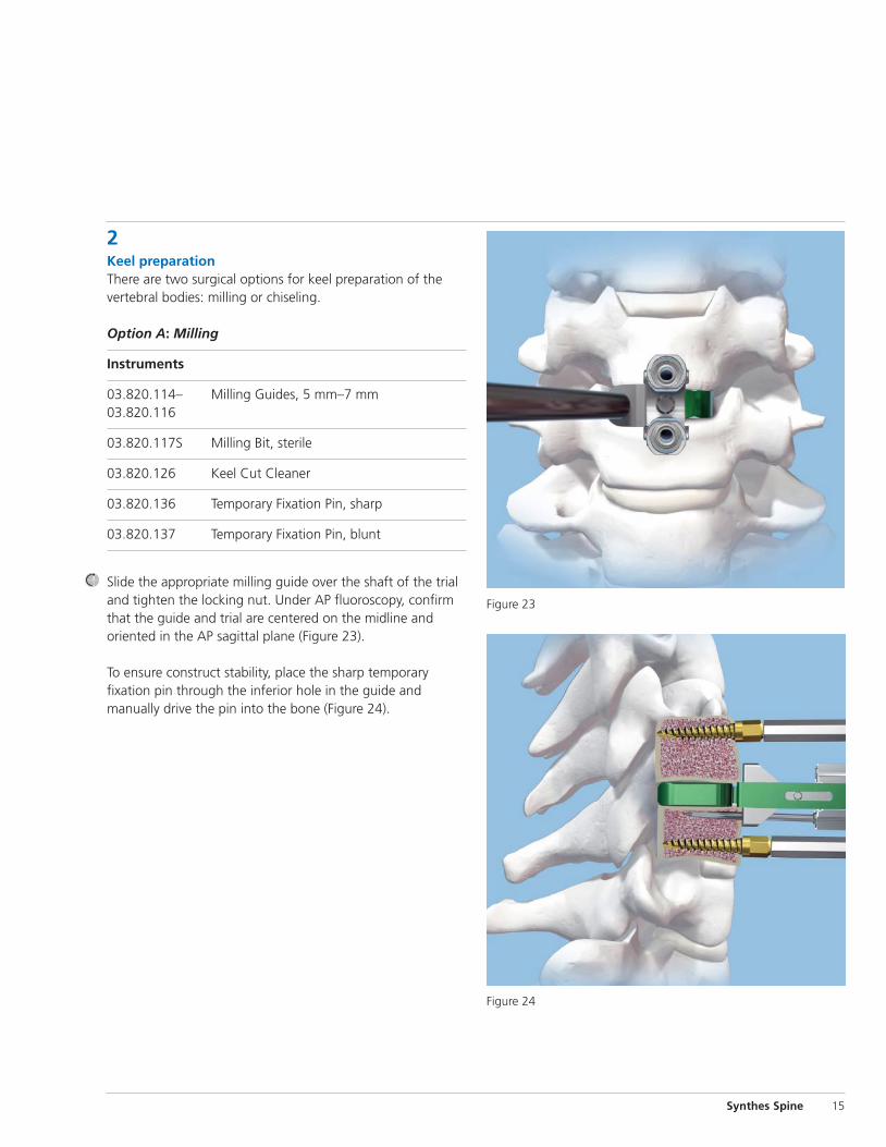
Slide the appropriate milling guide over the shaft of the trialand tighten the locking nut. Under AP fluoroscopy, confirmthat the guide and trial are centered on the midline and oriented in the AP sagittal plane (Figure 23).
To ensure construct stability, place the sharp temporary fixation pin through the inferior hole in the guide and manually drive the pin into the bone (Figure 24).
Figure 24
Figure 23
16 Synthes Spine ProDisc-C Total Disc Replacement
Implantation continued
2Keel preparation continued
Option A: Milling continued
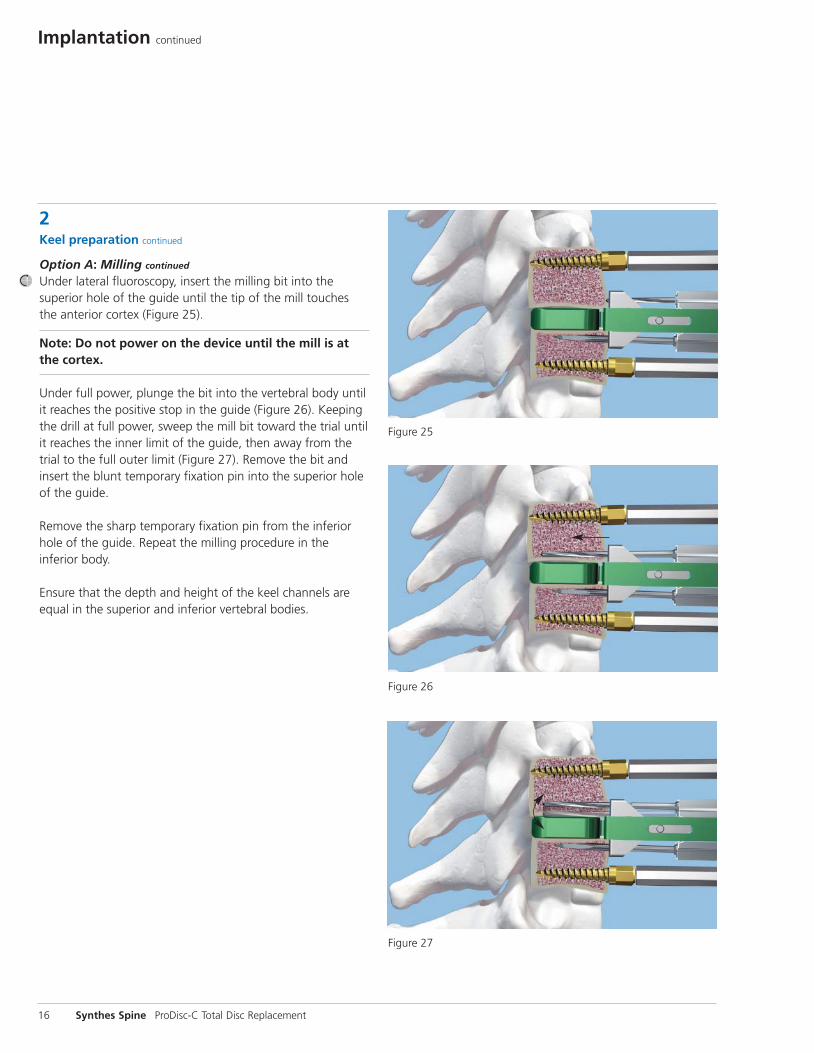
Under lateral fluoroscopy, insert the milling bit into the superior hole of the guide until the tip of the mill touchesthe anterior cortex (Figure 25).
Note: Do not power on the device until the mill is atthe cortex.
Under full power, plunge the bit into the vertebral body untilit reaches the positive stop in the guide (Figure 26). Keepingthe drill at full power, sweep the mill bit toward the trial untilit reaches the inner limit of the guide, then away from thetrial to the full outer limit (Figure 27). Remove the bit and insert the blunt temporary fixation pin into the superior holeof the guide.
Remove the sharp temporary fixation pin from the inferiorhole of the guide. Repeat the milling procedure in the inferior body.
Ensure that the depth and height of the keel channels areequal in the superior and inferior vertebral bodies.
Figure 25
Figure 26
Figure 27

Synthes Spine 17
Figure 28
Remove the guide and trial. Under fluoroscopic control, usethe keel cut cleaner to verify the depth of the keel channelsand to remove any bony debris from both the superior andinferior vertebral bodies (Figure 28). Irrigate the wound toensure the disc space is clear of debris.

18 Synthes Spine ProDisc-C Total Disc Replacement
2Keel preparation continued
Option B: Chiseling
Instruments
03.820.113 Slotted Mallet
03.820.119– Primary Chisels, 5 mm–7 mm 03.820.121
03.820.122– Secondary Chisels, 5 mm–7 mm03.820.124
03.820.126 Keel Cut Cleaner
Compress the vertebral body retainer onto the trial. Slide the primary chisel over the shaft of the trial. Under AP fluoro scopy, confirm the chisel is centered on midline and oriented in the AP sagittal plane. Under lateral fluoroscopy,advance the chisel into the vertebral bodies with the slottedmallet. The trajectory of the chisel should remain on midlinewhile advancing. Continue advancing the chisel until it is fully seated on the trial (Figure 29).
Ensure that the depth and height of the keel channels areequal in the superior and inferior vertebral bodies. Repeatthe chisel procedure with the secondary chisel (Figure 30).
Remove the chisel and trial. Under fluoroscopic control, usethe keel cut cleaner to verify the depth of the keel channelsand to remove any bony debris from both the superior andinferior vertebral bodies (see Figure 28 on page 17). Irrigatethe wound to ensure the disc space is clear of debris.
Implantation continued
Figure 29
Figure 30
3Implant insertion
Instruments
03.820.129 Implant Inserter
03.820.130S– Inserter Tips03.820.142S
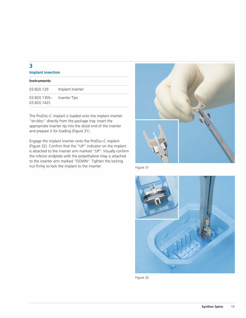
The ProDisc-C implant is loaded onto the implant inserter“en-bloc” directly from the package tray. Insert the appropriate inserter tip into the distal end of the inserter and prepare it for loading (Figure 31).
Engage the implant inserter onto the ProDisc-C implant (Figure 32). Confirm that the “UP“ indicator on the implantis attached to the inserter arm marked “UP“. Visually confirmthe inferior endplate with the polyethylene inlay is attachedto the inserter arm marked “DOWN“. Tighten the lockingnut firmly to lock the implant to the inserter.
Synthes Spine 19
Figure 32
Figure 31
Implantation continued
20 Synthes Spine ProDisc-C Total Disc Replacement
3Implant insertion continued
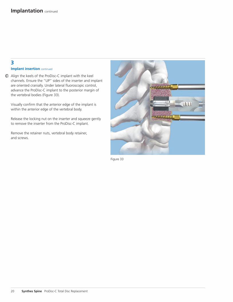
Align the keels of the ProDisc-C implant with the keel channels. Ensure the “UP” sides of the inserter and implantare oriented cranially. Under lateral fluoroscopic control,advance the ProDisc-C implant to the posterior margin of the vertebral bodies (Figure 33).
Visually confirm that the anterior edge of the implant iswithin the anterior edge of the vertebral body.
Release the locking nut on the inserter and squeeze gently to remove the inserter from the ProDisc-C implant.
Remove the retainer nuts, vertebral body retainer, and screws.
Figure 33

Synthes Spine 21
Figure 34
Figure 35
Confirm final implant position with lateral and AP imaging(Figures 34 and 35).
Copious saline lavage is recommended to remove osteogenic stimuli (blood/bone marrow). Apply standard homeostatic techniques to control bleeding.
Close the surgical wound in a routine fashion.
22 Synthes Spine ProDisc-C Total Disc Replacement
Postoperative care
Patients can begin ambulating immediately postoperatively.A soft or hard collar may be used if deemed necessary. Patients should be instructed to avoid prolonged or strenuous activity; heavy physical activity should not be resumed until the surgeon is confident, based on review of postoperative radiographs, that the implant is stable and functioning. Patients should be instructed to immediately report any change in their pain or neurologic status.
Implant removalApproach the level through the original anterior incision. Expose, identify and isolate the ProDisc-C implant from anyoverlying scar tissue. Excise any bony tissue from the anterioraspect of the endplates and keels to expose the implant-bone junction. Use an interbody distractor or retainer deviceto distract the disc space. Using a fine osteotome, pry the superior endplate from the vertebral body and extract the superior endplate from the space with a Kocher clamp orother grasping instrument. Repeat this technique on the inferior endplate. If distraction is not achievable, it may benecessary to pry the polyethylene insert from the inferiorendplate first, before removing the superior and inferior endplates.
Should it be necessary to remove a ProDisc-C Total Disc Replacement, please contact Synthes Spine to receive instructions regarding data collection, including histopatho-logical, mechanical, and adverse event information. All explanted devices must be returned to Synthes Spine for analysis.
Please note that the ProDisc-C Total Disc Replacement shouldbe removed as carefully as possible in order to keep the implant and surrounding tissue intact. Also, please providedescriptive information about the gross appearance of the device in situ, as well as descriptions of the removal methods, i.e., intact or in pieces.
Note: All implant removals must be reported immediately to Synthes Spine.
Postoperative Care and Implant Removal
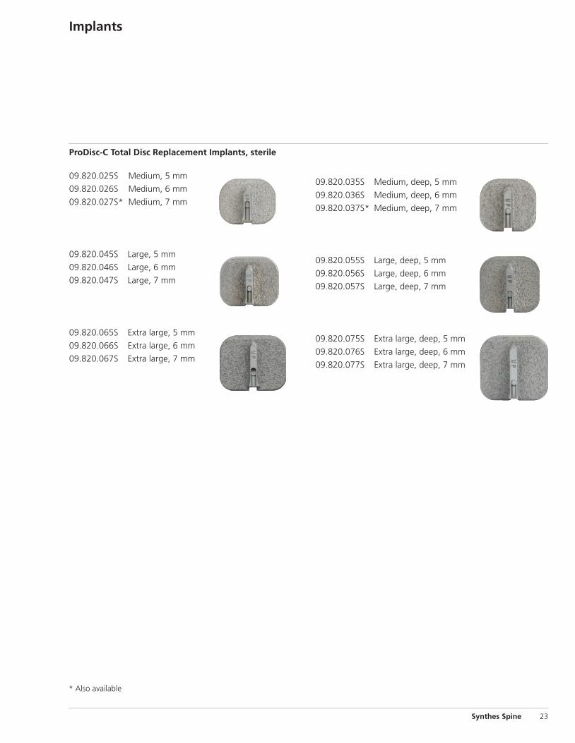
ProDisc-C Total Disc Replacement Implants, sterile
09.820.025S Medium, 5 mm
09.820.026S Medium, 6 mm
09.820.027S* Medium, 7 mm
09.820.045S Large, 5 mm
09.820.046S Large, 6 mm
09.820.047S Large, 7 mm
09.820.065S Extra large, 5 mm
09.820.066S Extra large, 6 mm
09.820.067S Extra large, 7 mm
09.820.035S Medium, deep, 5 mm
09.820.036S Medium, deep, 6 mm
09.820.037S* Medium, deep, 7 mm
09.820.055S Large, deep, 5 mm
09.820.056S Large, deep, 6 mm
09.820.057S Large, deep, 7 mm
09.820.075S Extra large, deep, 5 mm
09.820.076S Extra large, deep, 6 mm
09.820.077S Extra large, deep, 7 mm
Implants
Synthes Spine 23
* Also available

24 Synthes Spine ProDisc-C Total Disc Replacement
Instruments
03.820.000 Handle, for Trial Implants
Trial Implants, medium03.820.025 5 mm03.820.026 6 mm03.820.027* 7 mm
Trial Implants, medium, deep 03.820.035 5 mm03.820.036 6 mm03.820.037* 7 mm
Trial Implants, large03.820.045 5 mm03.820.046 6 mm03.820.047* 7 mm
Trial Implants, large, deep03.820.055 5 mm03.820.056 6 mm03.820.057* 7 mm
Trial Implants, extra large03.820.065 5 mm03.820.066 6 mm03.820.067* 7 mm
Trial Implants, extra large, deep 03.820.075 5 mm03.820.076 6 mm03.820.077* 7 mm
03.820.100 Awl, 12 mm
*Also available

Synthes Spine 25
03.820.111 Vertebral Body Retainer
03.820.101 Self-Retaining Screwdriver
Retainer Screws03.820.102 3.5 mm x 12 mm
03.820.103 3.5 mm x 14 mm
03.820.104 3.5 mm x 16 mm
03.820.105 3.5 mm x 18 mm
03.820.106 4.5 mm x 13 mm
03.820.107 4.5 mm x 15 mm
03.820.108 4.5 mm x 17 mm
03.820.109 4.5 mm x 19 mm
03.820.110 Retainer Nut
03.820.112 Vertebral Distractor

Instruments continued
03.820.126 Keel Cut Cleaner
26 Synthes Spine ProDisc-C Total Disc Replacement
03.820.113 Slotted Mallet
03.820.117S Milling Bit, sterile
Milling Guides 03.820.114 5 mm03.820.115 6 mm03.820.116* 7 mm
Primary Chisels 03.820.119 5 mm03.820.120 6 mm03.820.121* 7 mm
Secondary Chisels 03.820.122 5 mm03.820.123 6 mm03.820.124* 7 mm
03.820.128 Chisel Cleaner
*Also available

Synthes 27
03.820.129 Implant Inserter
Inserter Tips, sterilefor Medium and Medium Deep Implants,
03.820.130S 5 mm height03.820.131S 6 mm height03.820.132S* 7 mm height
for Large and Large Deep Implants03.820.133S 5 mm height03.820.134S 6 mm height03.820.135S 7 mm height
for Extra Large and Extra Large Deep Implants03.820.140S 5 mm height03.820.141S 6 mm height03.820.142S 7 mm height
Temporary Fixation Pins03.820.136 sharp03.820.137 blunt
03.820.143 2.0 mm Hexagonal Screwdriver
03.820.144 Tamp
*Also available

28 Synthes Spine ProDisc-C Total Disc Replacement
ProDisc-C Instrument and Implant Set (01.820.003)
Graphic Case60.820.001 Graphic Case, for ProDisc-C Instruments
Instruments (in graphic case)03.820.000 Handle, for Trial Implants, 2 ea.
Trial Implants
03.820.025 Medium, 5 mm
03.820.026 Medium, 6 mm
03.820.035 Medium, deep, 5 mm
03.820.036 Medium, deep, 6 mm
03.820.045 Large, 5 mm
03.820.046 Large, 6 mm
03.820.055 Large, deep, 5 mm
03.820.056 Large, deep, 6 mm
03.820.065 Extra large, 5 mm
03.820.066 Extra large, 6 mm
03.820.075 Extra large, deep, 5 mm
03.820.076 Extra large, deep, 6 mm
03.820.100 Awl, 12 mm
03.820.101 Self-Retaining Screwdriver, 2 ea.
Retainer Screws
03.820.102 3.5 mm x 12 mm, 2 ea.
03.820.103 3.5 mm x 14 mm, 2 ea.
03.820.104 3.5 mm x 16 mm, 2 ea.
03.820.105 3.5 mm x 18 mm, 2 ea.
03.820.106 4.5 mm x 13 mm
03.820.107 4.5 mm x 15 mm
03.820.108 4.5 mm x 17 mm
03.820.109 4.5 mm x 19 mm
03.820.110 Retainer Nut, 6 ea.
03.820.111 Vertebral Body Retainer
03.820.112 Vertebral Distractor
03.820.113 Slotted Mallet
03.820.114 Milling Guide, 5 mm
03.820.115 Milling Guide, 6 mm
03.820.119 Primary Chisel, 5 mm
03.820.120 Primary Chisel, 6 mm
03.820.122 Secondary Chisel, 5 mm
03.820.123 Secondary Chisel, 6 mm
03.820.126 Keel Cut Cleaner
03.820.128 Chisel Cleaner
03.820.129 Implant Inserter
03.820.136 Temporary Fixation Pin, sharp, 2 ea.
03.820.137 Temporary Fixation Pin, Blunt
03.820.143 2.0 mm Hexagonal Screwdriver
03.820.144 Tamp
Note: For additional information, please refer to package insert. For detailed cleaning and sterilization instructions, please refer tohttp://us.synthes.com/Medical+Community /Cleaning+and+Sterilization.htmor to the below listed inserts, which will be included in the shipping container:– Processing Synthes Reusable Medical Devices—Instruments, Instrument Trays
and Graphic Cases—DJ1305
Synthes Spine
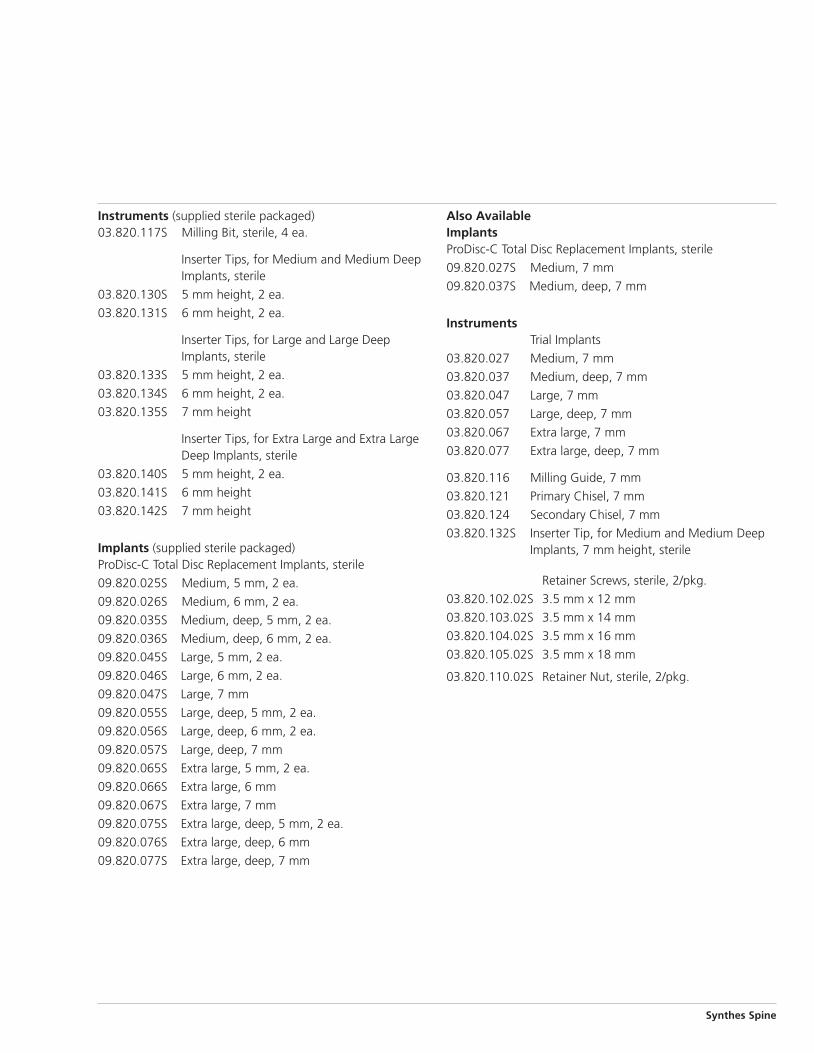
Instruments (supplied sterile packaged)03.820.117S Milling Bit, sterile, 4 ea.
Inserter Tips, for Medium and Medium DeepImplants, sterile
03.820.130S 5 mm height, 2 ea.
03.820.131S 6 mm height, 2 ea.
Inserter Tips, for Large and Large DeepImplants, sterile
03.820.133S 5 mm height, 2 ea.
03.820.134S 6 mm height, 2 ea.
03.820.135S 7 mm height
Inserter Tips, for Extra Large and Extra LargeDeep Implants, sterile
03.820.140S 5 mm height, 2 ea.
03.820.141S 6 mm height
03.820.142S 7 mm height
Implants (supplied sterile packaged)ProDisc-C Total Disc Replacement Implants, sterile
09.820.025S Medium, 5 mm, 2 ea.
09.820.026S Medium, 6 mm, 2 ea.
09.820.035S Medium, deep, 5 mm, 2 ea.
09.820.036S Medium, deep, 6 mm, 2 ea.
09.820.045S Large, 5 mm, 2 ea.
09.820.046S Large, 6 mm, 2 ea.
09.820.047S Large, 7 mm
09.820.055S Large, deep, 5 mm, 2 ea.
09.820.056S Large, deep, 6 mm, 2 ea.
09.820.057S Large, deep, 7 mm
09.820.065S Extra large, 5 mm, 2 ea.
09.820.066S Extra large, 6 mm
09.820.067S Extra large, 7 mm
09.820.075S Extra large, deep, 5 mm, 2 ea.
09.820.076S Extra large, deep, 6 mm
09.820.077S Extra large, deep, 7 mm
Also AvailableImplantsProDisc-C Total Disc Replacement Implants, sterile
09.820.027S Medium, 7 mm
09.820.037S Medium, deep, 7 mm
InstrumentsTrial Implants
03.820.027 Medium, 7 mm
03.820.037 Medium, deep, 7 mm
03.820.047 Large, 7 mm
03.820.057 Large, deep, 7 mm
03.820.067 Extra large, 7 mm
03.820.077 Extra large, deep, 7 mm
03.820.116 Milling Guide, 7 mm
03.820.121 Primary Chisel, 7 mm
03.820.124 Secondary Chisel, 7 mm
03.820.132S Inserter Tip, for Medium and Medium DeepImplants, 7 mm height, sterile
Retainer Screws, sterile, 2/pkg.
03.820.102.02S 3.5 mm x 12 mm
03.820.103.02S 3.5 mm x 14 mm
03.820.104.02S 3.5 mm x 16 mm
03.820.105.02S 3.5 mm x 18 mm
03.820.110.02S Retainer Nut, sterile, 2/pkg.

Synthes Spine1302 Wrights Lane EastWest Chester, PA 19380Telephone: (610) 719-5000To order: (800) 523-0322Fax: (610) 251-9056
Synthes (Canada) Ltd.2566 Meadowpine BoulevardMississauga, Ontario L5N 6P9Telephone: (905) 567-0440To order: (800) 668-1119Fax: (905) 567-3185
© 2008 Synthes, Inc. or its affiliates. All rights reserved. ProDisc and Synthes are trademarks of Synthes, Inc. or its affiliates. Printed in U.S.A. 9/11 J7501-E
www.synthesprodisc.comwww.synthes.com