Embed Size (px)
Citation preview
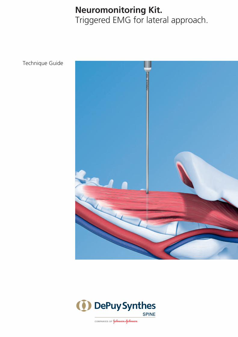
Neuromonitoring Kit.Triggered EMG for lateral approach.
Technique Guide

Neuromonitoring Kit Technique Guide Synthes 1
Table of Contents
Introduction
Application
Product Information
Principle of t-EMG Monitoring 2
Neuromonitoring Kit 2
t-EMG for Lateral Approach 3
AO Principles 4
Indications and Contraindications 5
Surgery Planning 6
Neuromonitoring Preparation 8
Triggered EMG Monitoring 14
Instruments 17
Image intensifier control
WarningThis description alone does not provide sufficient background for direct use of the instrument set. Instruction by a surgeon experienced in handling these instruments is highly recommended.
Reprocessing, Care and Maintenance of Synthes InstrumentsFor general guidelines, function control and dismantling of multi-part instruments, please contact your local sales representative or refer to: www.synthes.com/reprocessing
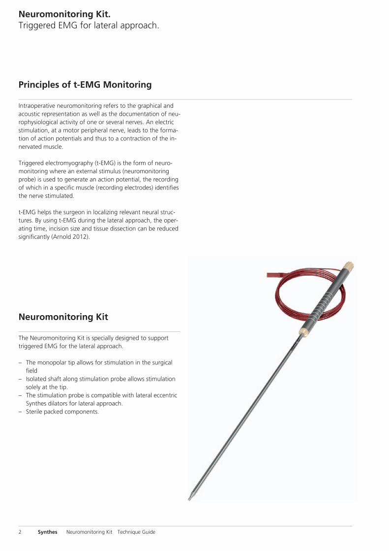
The Neuromonitoring Kit is specially designed to support triggered EMG for the lateral approach.
– The monopolar tip allows for stimulation in the surgical fi eld
– Isolated shaft along stimulation probe allows stimulation solely at the tip.
– The stimulation probe is compatible with lateral eccentric Synthes dilators for lateral approach.
– Sterile packed components.
Intraoperative neuromonitoring refers to the graphical and acoustic representation as well as the documentation of neu-rophysiological activity of one or several nerves. An electric stimulation, at a motor peripheral nerve, leads to the forma-tion of action potentials and thus to a contraction of the in-nervated muscle.
Triggered electromyography (t-EMG) is the form of neuro-monitoring where an external stimulus (neuromonitoring probe) is used to generate an action potential, the recording of which in a specifi c muscle (recording electrodes) identifi es the nerve stimulated.
t-EMG helps the surgeon in localizing relevant neural struc-tures. By using t-EMG during the lateral approach, the oper-ating time, incision size and tissue dissection can be reduced signifi cantly (Arnold 2012).
Neuromonitoring Kit. Triggered EMG for lateral approach.
Principles of t-EMG Monitoring
Neuromonitoring Kit
2 Synthes Neuromonitoring Kit Technique Guide

During the lateral approach to the spine with a blunt dissec-tion through the psoas muscle, iatrogenic injuries of the nerve roots, the lumbar plexus and/or individual nerves are most likely to occur.
Neural injury during this surgery can be caused by compres-sion, stretch, transection and ischemia of nervous structures as well as operative hematoma in the psoas.
Using t-EMG during transpsoatic approaches supports the surgeon in the detection of motoric neural structures and in doing so, allows the surgeon to adjusts his/her approach to reduce the occurrence of nerve damage.
t-EMG for Lateral Approach
Neuromonitoring Kit Technique Guide Synthes 3

AO Principles
In 1958, the AO formulated four basic principles, which havebecome the guidelines for internal fixation.1 They are:– Anatomic reduction– Stable internal fixation– Preservation of blood supply– Early, active mobilization
The fundamental aims of fracture treatment in the limbs andfusion of the spine are the same. A specific goal in thespine is returning as much function as possible to the injuredneural elements.2
AO Principles as Applied to the Spine 3
Anatomic alignmentRestoration of normal spinal alignment to improve thebiomechanics of the spine.
Stable internal fixationStabilization of the spinal segment to promote bony fusion.
Preservation of blood supplyCreation of an optimal environment for fusion.
Early, active mobilizationMinimization of damage to the spinal vasculature, dura, andneural elements, which may contribute to pain reduction andimproved function for the patient.
1 Müller ME, Allgöwer M, Schneider R, Willenegger H (1995) Manual of InternalFixation. 3rd, expanded and completely revised ed. 1991. Berlin, Heidelberg,New York: Springer2 ebd.3 Aebi M, Arlet V, Webb JK (2007). AOSPINE Manual (2 vols.), Stuttgart, New York:Thieme
4 Synthes Neuromonitoring Kit Technique Guide
Indications and Contraindications
The Neuromonitoring Kit is intended for use in intraoperative spinal procedures for patient connected intraoperative neu-romonitoring where an appropriate neuromonitoring ma-chine is also used. The Neuromonitoring Kit allows for trig-gered EMG stimulation and subsequent recording of the stimulus from the muscle whose nerve was initially stimu-lated.
For use of the Neuromonitoring Kit in conjunction with surgi-cal systems and the EMG neuromonitoring machine refer to the associated product information for details on their use, precautions, warnings and side effects.
IndicationsThe Neuromonitoring Kit is indicated for intraoperative use during lateral approach surgeries utilizing the Synthes lateral product family where the patient’s peripheral motor neural structures are at risk of damage due to manipulation. Please refer to the indications of the associated system used.
Contraindications– Patients with pre-existing nerve damage in the vicinity of
or below the area of treatment– Patients with illnesses or conditions resulting in reduced
nerve conduction– In surgeries where paralyzing anesthetic agents are being
used– In surgeries involving direct stimulation of the central ner-
vous system– Contraindications associated with respective system(s)
Neuromonitoring Kit Technique Guide Synthes 5

Before the surgery is scheduled with intraoperative neuro-monitoring (IONM), the patient needs to be examined on neurological and physiological conditions. If nerve impinge-ment or even permanent nerve injury is already present prior to surgery an induced action potential may be inhibited dur-ing surgery. This may lead to adverse events for the patient if the signal is not recorded during surgery.
Note: Consider other surgery approaches to avoid any com-plications if the above situation is presented.
Instruments
03.662.029 Handle for Neuromonitoring Stimulation Probe
03.662.027S Neuromonitoring Stimulation Probe
03.662.028S Electrode Kit for Neuromonitoring
Precaution: Only motoric nerves can be detected with trig-gered EMG. Special attention needs to be paid to sensoric nerves e.g. part of N. genitofemoralis which occurs from nerve roots L1 and L2 and runs obliquely through the psoas muscle. It exits the m. psoas major anteriorly approximately at disc level L2/3.
Warning: Do not use any muscle relaxant anesthetics.
Surgery Planning
6 Synthes Neuromonitoring Kit Technique Guide
Prepare the needed amount of probes and electrodes:
The Neuromonitoring Stimulation Probe contains one stimu-lation probe with cable and one reference electrode.The Electrode Kit for Neuromonitoring contains four paired elec-trodes and a ground electrode. One pack is sufficient to monitor four muscles. If more muscles need to be monitored, prepare more elec-trodes (for instance another Electrode Kit for Neuromonitor-ing).
One stimulation probe is sufficient to map nerves in the psoas. If the nerves around the dilators need to be checked in parallel, a second probe might be helpful.
Have all imaging equipment available for visualization of in-strumentation during the procedure.
Neuromonitoring Kit Technique Guide Synthes 7
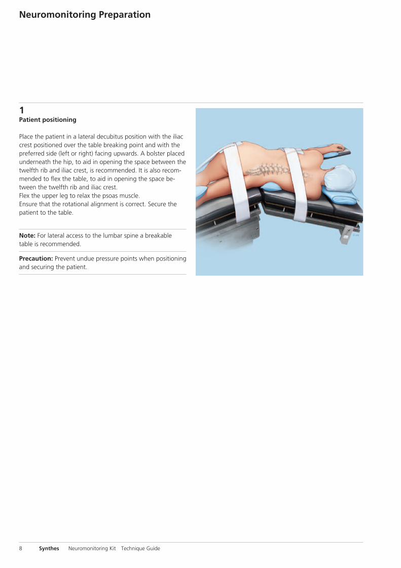
1Patient positioning
Place the patient in a lateral decubitus position with the iliac crest positioned over the table breaking point and with the preferred side (left or right) facing upwards. A bolster placed underneath the hip, to aid in opening the space between the twelfth rib and iliac crest, is recommended. It is also recom-mended to flex the table, to aid in opening the space be-tween the twelfth rib and iliac crest.Flex the upper leg to relax the psoas muscle.Ensure that the rotational alignment is correct. Secure the patient to the table.
Note: For lateral access to the lumbar spine a breakable table is recommended.
Precaution: Prevent undue pressure points when positioning and securing the patient.
Neuromonitoring Preparation
8 Synthes Neuromonitoring Kit Technique Guide
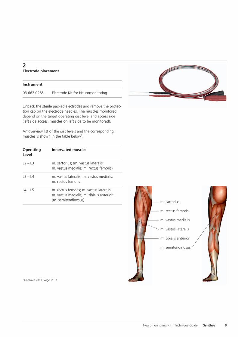
2Electrode placement
Instrument
03.662.028S Electrode Kit for Neuromonitoring
Unpack the sterile packed electrodes and remove the protec-tion cap on the electrode needles. The muscles monitored depend on the target operating disc level and access side (left side access, muscles on left side to be monitored).
An overview list of the disc levels and the corresponding muscles is shown in the table below1.
Operating Innervated musclesLevel
L2 – L3 m. sartorius; (m. vastus lateralis; m. vastus medialis; m. rectus femoris)
L3 – L4 m. vastus lateralis; m. vastus medialis; m. rectus femoris
L4 – L5 m. rectus femoris; m. vastus lateralis; m. vastus medialis; m. tibialis anterior; (m. semitendinosus)
1 Gonzalez 2009, Vogel 2011
Neuromonitoring Kit Technique Guide Synthes 9
m. sartorius
m. rectus femoris
m. vastus medialis
m. vastus lateralis
m. tibialis anterior
m. semitendinosus
2
1
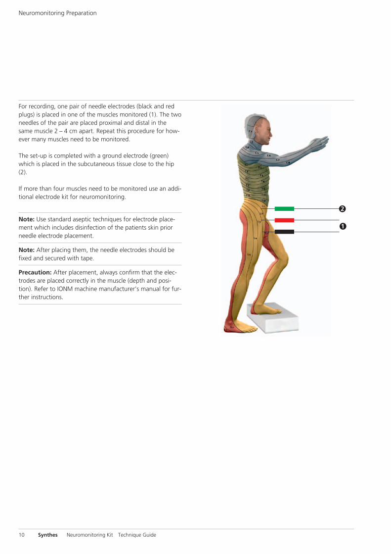
For recording, one pair of needle electrodes (black and red plugs) is placed in one of the muscles monitored (1). The two needles of the pair are placed proximal and distal in the same muscle 2 – 4 cm apart. Repeat this procedure for how-ever many muscles need to be monitored.
The set-up is completed with a ground electrode (green) which is placed in the subcutaneous tissue close to the hip (2).
If more than four muscles need to be monitored use an addi-tional electrode kit for neuromonitoring.
Note: Use standard aseptic techniques for electrode place-ment which includes disinfection of the patients skin prior needle electrode placement.
Note: After placing them, the needle electrodes should be fixed and secured with tape.
Precaution: After placement, always confirm that the elec-trodes are placed correctly in the muscle (depth and posi-tion). Refer to IONM machine manufacturer’s manual for fur-ther instructions.
Neuromonitoring Preparation
10 Synthes Neuromonitoring Kit Technique Guide
3Connect electrodes to IONM machine
The placed electrodes are connected to the corresponding input of the IONM system.
Refer to the manufacturer’s manual for detailed instructions.
The electrodes can be attached to DIN 42802 connections on neuromonitoring machines with basic capability of t-EMG monitoring.
Precaution: The electrodes may only be connected to devices, which are conforming to medical device directive 93/42 EEC.
Before use make sure that the electrode can be connected with the device for intended application.
Neuromonitoring Kit Technique Guide Synthes 11

4Electrode check
When all required electrodes are placed, refer to the manu-facturer’s manual to check electrodes and choose the correct program on the IONM system.
5Sterile draping of patient
Cover the patient in sterile cloth and perform a lateral and anterior-posterior fluoroscopic check to locate the correct level to operate.
Neuromonitoring Preparation
12 Synthes Neuromonitoring Kit Technique Guide
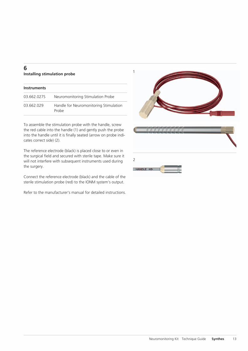
6Installing stimulation probe
Instruments
03.662.027S Neuromonitoring Stimulation Probe
03.662.029 Handle for Neuromonitoring Stimulation Probe
To assemble the stimulation probe with the handle, screw the red cable into the handle (1) and gently push the probe into the handle until it is fi nally seated (arrow on probe indi-cates correct side) (2).
The reference electrode (black) is placed close to or even in the surgical fi eld and secured with sterile tape. Make sure it will not interfere with subsequent instruments used during the surgery.
Connect the reference electrode (black) and the cable of the sterile stimulation probe (red) to the IONM system’s output.
Refer to the manufacturer’s manual for detailed instructions.
Neuromonitoring Kit Technique Guide Synthes 13
1
2
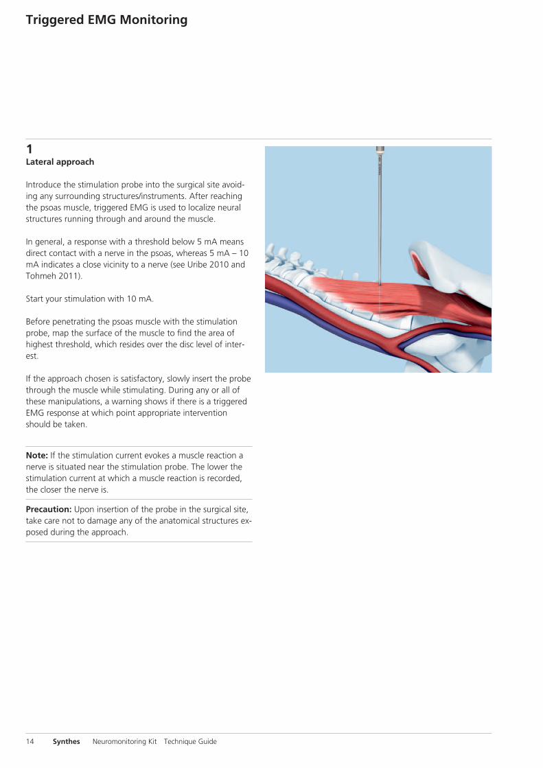
1Lateral approach
Introduce the stimulation probe into the surgical site avoid-ing any surrounding structures/instruments. After reaching the psoas muscle, triggered EMG is used to localize neural structures running through and around the muscle.
In general, a response with a threshold below 5 mA means direct contact with a nerve in the psoas, whereas 5 mA – 10 mA indicates a close vicinity to a nerve (see Uribe 2010 and Tohmeh 2011).
Start your stimulation with 10 mA.
Before penetrating the psoas muscle with the stimulation probe, map the surface of the muscle to find the area of highest threshold, which resides over the disc level of inter-est.
If the approach chosen is satisfactory, slowly insert the probe through the muscle while stimulating. During any or all of these manipulations, a warning shows if there is a triggered EMG response at which point appropriate intervention should be taken.
Note: If the stimulation current evokes a muscle reaction a nerve is situated near the stimulation probe. The lower the stimulation current at which a muscle reaction is recorded, the closer the nerve is.
Precaution: Upon insertion of the probe in the surgical site, take care not to damage any of the anatomical structures ex-posed during the approach.
Triggered EMG Monitoring
14 Synthes Neuromonitoring Kit Technique Guide
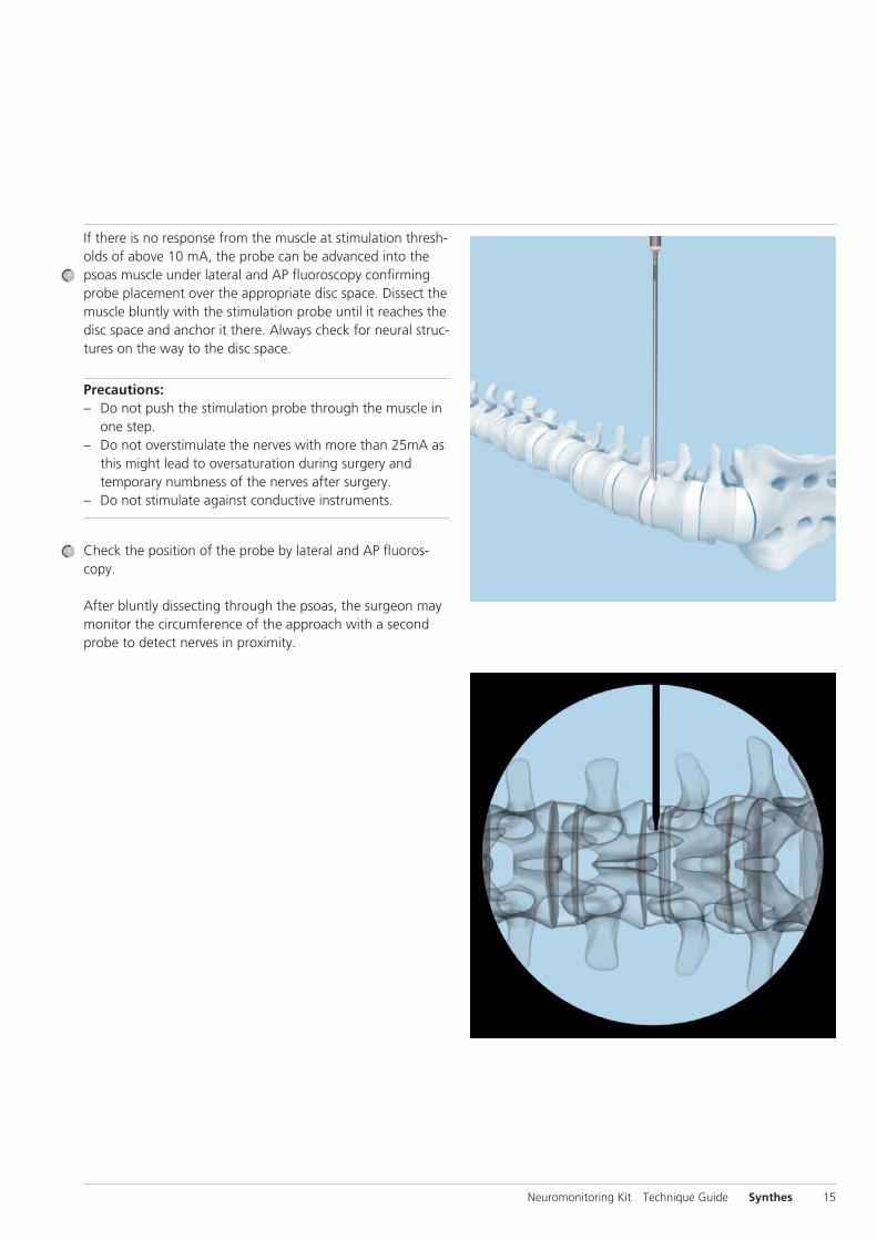
If there is no response from the muscle at stimulation thresh-olds of above 10 mA, the probe can be advanced into the psoas muscle under lateral and AP fluoroscopy confirming probe placement over the appropriate disc space. Dissect the muscle bluntly with the stimulation probe until it reaches the disc space and anchor it there. Always check for neural struc-tures on the way to the disc space.
Precautions:– Do not push the stimulation probe through the muscle in
one step.– Do not overstimulate the nerves with more than 25mA as
this might lead to oversaturation during surgery and temporary numbness of the nerves after surgery.
– Do not stimulate against conductive instruments.
Check the position of the probe by lateral and AP fluoros-copy.
After bluntly dissecting through the psoas, the surgeon may monitor the circumference of the approach with a second probe to detect nerves in proximity.
Neuromonitoring Kit Technique Guide Synthes 15
2Interpreting the signals
Refer to the manufacturer’s manual for instructions on how to read the monitored signals (i.e. curves on display).
Intraoperative Neuromonitoring
16 Synthes Neuromonitoring Kit Technique Guide
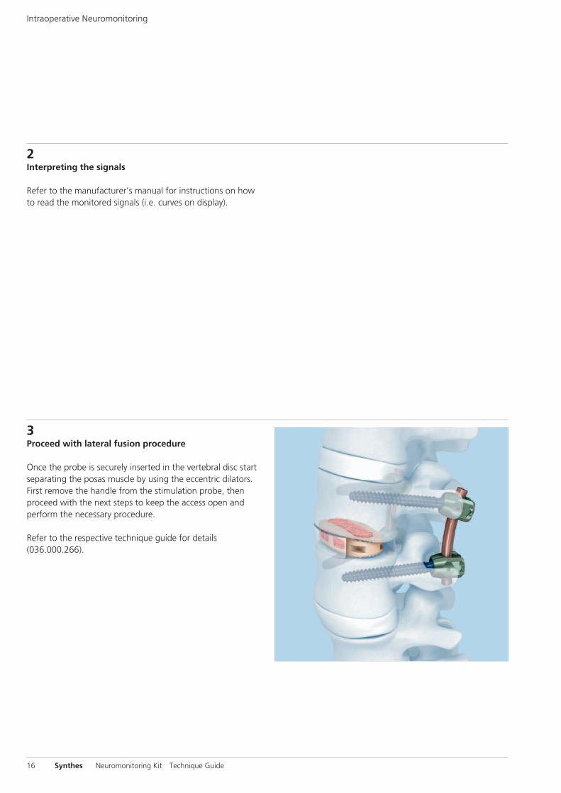
3Proceed with lateral fusion procedure
Once the probe is securely inserted in the vertebral disc start separating the posas muscle by using the eccentric dilators. First remove the handle from the stimulation probe, then proceed with the next steps to keep the access open and perform the necessary procedure.
Refer to the respective technique guide for details (036.000.266).
Neuromonitoring Kit Technique Guide Synthes 17
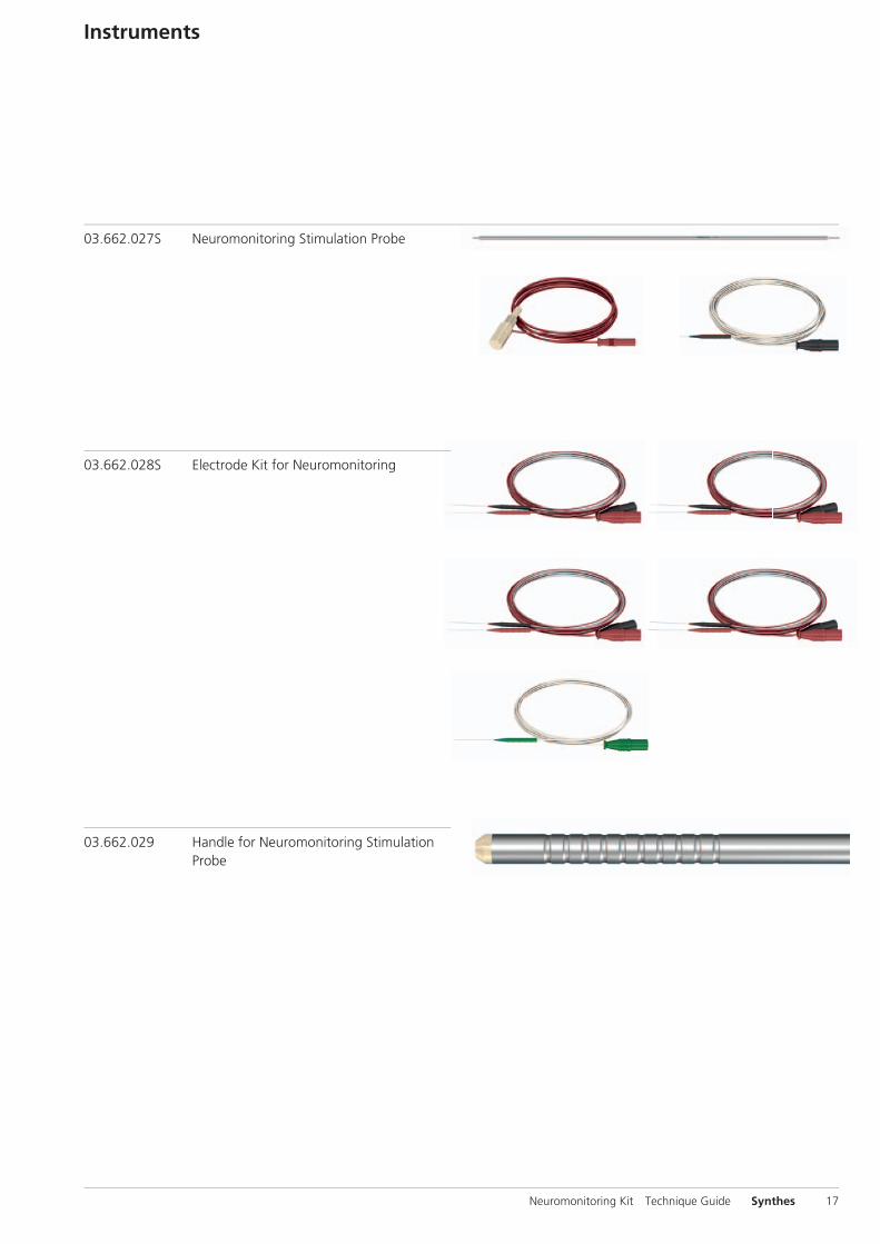
Instruments
03.662.027S Neuromonitoring Stimulation Probe
03.662.028S Electrode Kit for Neuromonitoring
03.662.029 Handle for Neuromonitoring Stimulation Probe
Bibliography
Arnold PM, KK Anderson, RA McGuire Jr. The lateral trans-psoas approach to the lumbar and thoracic spine: A review. Surg Neurol Int. 3(Suppl 3) (2012): 198-215.
Gonzalez AA, D Jeyanandarajan, C Hansen, et al. Intraopera-tive neurophysiological monitoring during spine surgery: a review. Neurosurg Focus 27(4) (Oct 2009): E6.
Moro T, S Kikuchi, S Konno et al. An anatomic study of the lumbar plexus with respect to retroperitoneal endoscopic surgery. Spine (Phila Pa 1976). 1;28(5) (March 2003): 423-428.
Regev GJ, et al. Morphometric analysis of the ventral nerve roots and retroperitoneal vessels with respect to the mini-mally invasive lateral approach in normal and deformed spines. Spine (Phila Pa 1976). 2009 May 20;34(12):1330-5.
Tohmeh AG, WB Rodgers, MD Peterson. Dynamically evoked, discrete-threshold electromyography in the extreme lateral interbody fusion approach. J Neurosurg Spine 14(1) (Jan 2011): 31-37.
Uribe JS, FL Vale, E Dakwar. Electromyographic monitoring and its anatomical implications in minimally invasive spine surgery. Spine (Phila Pa 1976) 15;35(26 Suppl) (Dec 2010): 368-374.
Vogel P. Kursbuch klinische Neurophysiologie: EMG – ENG – Evozierte Potenziale. 3rd edition. Stuttgart: Georg Thieme Verlag. 2011.
18 Synthes Neuromonitoring Kit Technique Guide

Neuromonitoring Kit Technique Guide Synthes 19

20 Synthes Neuromonitoring Kit Technique Guide

Neuromonitoring Kit Technique Guide Synthes 21

0123All technique guides are available as PDF files at www.synthes.com/lit
Ö036.001.547öAAYä
036.
001.
549
vers
ion
AA
12
/201
2 50
1477
45
© S
ynth
es, I
nc. o
r its
affi
liate
s Su
bjec
t to
mod
ifica
tions
Sy
nthe
s is
a t
rade
mar
k of
Syn
thes
, Inc
. or
its a
ffilia
tes