Embed Size (px)
Citation preview

1
GOVERNMENT OF INDIA
MINISTRY OF SKILL DEVELOPMENT & ENTREPRENEURSHIP DIRECTORATE GENERAL OF TRAINING
COMPETENCY BASED CURRICULUM
TECHNICIAN ELECTRONICS SYSTEM DESIGN AND REPAIR
(Duration: Two Years)
CRAFTSMEN TRAINING SCHEME (CTS)
NSQF LEVEL- 5
SECTOR – ELECTRONICS & HARDWARE

TECHNICIAN ELECTRONICS SYSTEM DESIGN AND REPAIR
(Engineering Trade)
(Designed in 2021)
Version: 1.0
CRAFTSMEN TRAINING SCHEME (CTS)
NSQF LEVEL- 5
Developed By
Ministry of Skill Development and Entrepreneurship
Directorate General of Training
Sectoral Trade Course Committee of Electronics & Hardware Sector
& CENTRAL STAFF TRAINING AND RESEARCH INSTITUTE
EN-81, Sector-V, Salt Lake City, Kolkata – 700 091
www.cstaricalcutta.gov.in

S No. Topics Page No.
1. Course Information 1
2. Training System 3
3. Job Role 7
4. General Information 9
5. Learning Outcome 12
6. Assessment Criteria 14
7. Trade Syllabus 21
Annexure I(List of Trade Tools & Equipment) 52
Annexure II (List of Trade experts) 55
CONTENTS
1
Technician Electronics System Design & Manufacturing
During the two-year duration of Technician Electronics System Design and Repair trade a
candidate is trained on professional skill, professional knowledge, Engineering Drawing, Workshop
Calculation & Science and Employability skill related to job role. In addition to this a candidate is
entrusted to undertake project work and extracurricular activities to build up confidence. The
Broad components covered professional skill, subjects are as below: -
During the two-year duration of Technician Electronics System Design and Repair trade a candidate is trained on professional skill, professional knowledge, Engineering Drawing, Workshop Calculation & Science and Employability skill related to job role. In addition to this a candidate is entrusted to undertake project work, On Job Training (OJT) and extracurricular activities to build up confidence. The Broad components covered professional skill, subjects are as below: - FIRST YEAR: In this year the trainee learns about safety and environment, use of fire extinguishers,
artificial respiratory resuscitation to begin with. He gets the idea of trade tools & its
standardization, Familiarize with basics of electricity, test the cable and measure the electrical
parameter. Skilling practice on different types & combination of cells for operation and
maintenance of batteries being done. Identify and test passive and active electronic components.
Construct and test unregulated and regulated power supplies. Practice soldering and de-soldering
of various types of electrical and electronic components on through hole PCBs. Able to achieve the
skill on SMD Soldering and De-soldering of discrete SMD components. Trainees will learn and
acquire handful skill of PCB designing using software and able to develop PCB. Assemble a
computer system, install OS, Practice with MS office. The candidate will be able to construct and
test amplifier, oscillator and wave shaping circuits. Testing of power electronic components.
Verifying the truth tables of various digital ICs by referring Data book. Practice circuit simulation
software to simulate and test various circuits. Identify various types of LEDs, LED displays and
interface them to a digital counter and test. Construct and test various circuits using linear ICs 741
& 555. Trainee will be able to operate DSO and perform various functions Electronics Measuring
instruments. They can construct and test analog and digital IC based application circuits as a part
of project work.
SECOND YEAR: In this year trainees will learn Embedded C Programming. Identify various Pins and
familiar with the pin function of 8051. Programming and debug applications using Embedded „C‟
on 8051 platform i.e. following the complete system architecture including memory, memory
blocks, timers, interrupts and power management, Configuring Timers on 8051 Microcontrollers,
Configuring Interrupts on 8051 Microcontrollers, Configuring Serial Port on 8051, Interfacing LCD
with 8051 Microcontrollers, Interfacing key board with 8051 Microcontrollers, Interfacing stepper
motor with 8051 Microcontrollers, Demonstrate the ability to apply Knowledge on PIC
Architectural Concepts, Programming and debug applications using Embedded „C‟ on PIC
platform, Configuring Timers of PIC Microcontrollers, Configuring Interrupts on PIC
Microcontrollers, Configuring Serial Port on PIC Microcontroller, Interfacing LCD with PIC
Microcontrollers, Interfacing stepper motor with PIC Microcontrollers, Gain Knowledge on various
sensors and Actuators application in embedded system and skill to incorporated and interface with
1. COURSE INFORMATION

2
Technician Electronics System Design and Repair
Embedded system and IoT based system application. Finally Trainees will acquire knowledge and
skill IoT application and its Components, IoT Protype Boards, ARM controller & Its programming
with C/C++, Micro Python (Node MCU, Arduino, Raspberry Pi, IoT Protocol & Gateway, IoT Cloud
platform & Application development (BLYNK, Thing speak, AWS/Azure)
3
Technician Electronics System Design and Repair
2.1 GENERAL
Directorate General of Training (DGT) under Ministry of Skill Development &
Entrepreneurship offers range of vocational training courses catering to the need of different
sectors of economy/ Labour market. The vocational training programmes are delivered under
aegis of Directorate General of Training (DGT). Craftsman Training Scheme (CTS) with variants and
Apprenticeship Training Scheme (ATS) are two pioneer programmes of DGT for propagating
vocational training.
Technician Electronics System Design and Repair trade under CTS is one of the most
popular courses delivered nationwide through network of ITIs. The course is of two years duration.
It mainly consists of Domain area and Core area. The Domain area (Trade Theory & Practical)
impart professional skills and knowledge, while Core area (Workshop Calculation and science,
Engineering Drawing and Employability Skills) impart requisite core skill & knowledge and life skills.
After passing out the training program, the trainee is awarded National Trade Certificate (NTC) by
DGT which is recognized worldwide.
Candidates need broadly to demonstrate that they are able to:
• Read & interpret technical parameters/documentation, plan and organize work processes,
identify necessary materials and tools;
• Perform task with due consideration to safety rules, accident prevention regulations and
environmental protection stipulations;
• Apply professional knowledge, core skills & employability skills while performing the job
and repair & maintenance work.
• Check the job with circuit diagrams/components as per drawing for functioning, diagnose
and rectify faults in the electronics components/module.
• Document the technical parameters in tabulation sheet related to the task undertaken.
2.2 PROGRESSION PATHWAYS:
• Can join industry as Technician Electronics system design and will progress further as Junior
Embedded Engineer, Specialist in Arduino based Embedded System Design, can rise up to
the level of Manager.
• Can become Entrepreneur in the related field.
• Can appear in 10+2 examination through National Institute of Open Schooling (NIOS) for
acquiring higher secondary certificate and can go further for General/ Technical education.
• Can take admission in diploma course in notified branches of Engineering by lateral entry.
• Can join Apprenticeship programme in different types of industries leading to National
Apprenticeship certificate (NAC).
• Can join Crafts Instructor Training Scheme (CITS) in the trade for becoming instructor in
ITIs.
2. TRAINING SYSTEM

4
Technician Electronics System Design and Repair
• Can join Advanced Diploma (Vocational) courses under DGT as applicable.
2.3 COURSE STRUCTURE:
Table below depicts the distribution of training hours across various course elements
during a period of two years: -
S No. Course Element Notional Training Hours
1st Year 2nd Year
1 Professional Skill (Trade Practical) 1000 1000
2 Professional Knowledge (Trade Theory) 280 360
3 Workshop Calculation & Science 80 80
4 Engineering Drawing 80 80
5 Employability Skills 160 80
Total 1600 1600
2.4 ASSESSMENT & CERTIFICATION:
The trainee will be tested for his skill, knowledge and attitude during the period of course
through formative assessment and at the end of the training programme through summative
assessment as notified by the DGT from time to time.
a) The Continuous Assessment (Internal) during the period of training will be done by Formative
assessment method by testing for assessment criteria listed against learning outcomes. The
training institute have to maintain individual trainee portfolio as detailed in assessment guideline.
The marks of internal assessment will be as per the formative assessment template provided on
www.bharatskills.gov.in.
b) The final assessment will be in the form of summative assessment. The All India trade Test for
awarding NTC will be conducted by Controller of examinations, DGT as per the guidelines. The
pattern and marking structure is being notified by DGT from time to time. The learning outcome
and assessment criteria will be basis for setting question papers for final assessment. The
examiner during final examination will also check individual trainee’s profile as detailed in
assessment guideline before giving marks for practical examination.
2.4.1 PASS REGULATION
For the purposes of determining the overall result, weightage of 100% is applied for six months
and one year duration courses and 50% weightage is applied to each examination for two years
courses. The minimum pass percent for Trade Practical and Formative assessment is 60% & for all
other subjects is 33%. There will be no Grace marks.

5
Technician Electronics System Design and Repair
2.4.2 ASSESSMENT GUIDELINE:
Appropriate arrangements should be made to ensure that there will be no artificial barriers
to assessment. The nature of special needs should be taken into account while undertaking
assessment. Due consideration to be given while assessing for team work, avoidance/reduction of
scrap/wastage and disposal of scarp/wastage as per procedure, behavioral attitude, sensitive to
environment and regularity in training. The sensitivity towards OSHE and self-learning attitude to
be considered while assessing competency.
Assessment will be evidence based comprising the following:
• Job carried out in labs/workshop
• Record book/ daily diary
• Answer sheet of assessment
• Viva-voce
• Progress chart
• Attendance and punctuality
• Assignment
• Project work
Evidences and records of internal (Formative) assessments are to be preserved until
forthcoming examination for audit and verification by examination body. The following marking
pattern to be adopted while assessing:
Performance Level Evidence
(a) Weightage in the range of 60 -75% to be allotted during assessment
For performance in this grade, the candidate
with occasional guidance and showing due
regard for safety procedures and practices,
has produced work which demonstrates
attainment of an acceptable standard of
craftsmanship.
• Demonstration of good skill in the use of
hand tools, machine tools and workshop
equipment
• 60-70% accuracy achieved while
undertaking different work with those
demanded by the component/job.
• A fairly good level of neatness and
consistency in the finish
• Occasional support in completing the
project/job.
(b)Weightage in the range of above75% - 90% to be allotted during assessment
For this grade, the candidate, with little
guidance and showing due regard for safety
• Good skill levels in the use of hand tools,
machine tools and workshop equipment

6
Technician Electronics System Design and Repair
\
procedures and practices, has produced work
which demonstrates attainment of a
reasonable standard of craftsmanship.
• 70-80% accuracy achieved while
undertaking different work with those
demanded by the component/job.
• A good level of neatness and
consistency in the finish
• Little support in completing the
project/job
(c) Weightage in the range of above 90% to be allotted during assessment
For performance in this grade, the candidate,
with minimal or no support in organization
and execution and with due regard for safety
procedures and practices, has produced work
which demonstrates attainment of a high
standard of craftsmanship.
• High skill levels in the use of hand tools,
machine tools and workshop equipment
• Above 80% accuracy achieved while
undertaking different work with those
demanded by the component/job.
• A high level of neatness and consistency
in the finish.
• Minimal or no support in completing the
project.

7
Technician Electronics System Design and Repair
Electronics Mechanic; Electronic Equipment Mechanic repairs electronic equipment, such as
computers, industrial controls, transmitters, and telemetering control systems following blueprints
and manufacturer’s specifications and using hand tools and test instruments. Tests faulty
equipment and applies knowledge of functional operation of electronic units and systems to
diagnose cause of malfunction. Tests electronic components and circuits to locate defects, using
instruments, such as oscilloscopes, signal generators, ammeters and voltmeters. Replaces
defective components and wiring and adjusts mechanical parts, using hand tools and soldering
iron. Aligns, adjusts and calibrates testing instruments. Maintains records of repairs, calibrations
and test.
Electronics Fitter, General; fits, assembles and repairs various kinds of electronic equipment in factory or workshop or at place of use. Examines drawings and wiring diagrams; checks parts for accuracy of fit and minor adjustments; assembles parts or mounts them on chassis or panels with aid of hand tools; installs and connects wiring, soldering joints equipment, diagnoses faults with aid of electronic testing equipment; dismantles equipment if required and replaces faulty parts or wiring. Electronic, Technician; applies electronic theory, principles of electrical circuits, electrical testing procedures, engineering mathematics, physics and related subjects to layout, build, test, troubleshoot, repair and modify developmental and production electronic equipment. Draws sketches to clarify design details and functional criteria of electronic units. Assembles experimental circuitry (bread board) or complete prototype model according to engineering instructions, technical manuals and knowledge of electronic systems and components and their functions. Recommends changes in circuitry or installation specifications to simplify assembly and maintenance. Sets up standard test apparatus or contrives test equipment and circuit, and conducts functional, operational, environmental and life tests to evaluate performance and reliability of prototype or production model. Analyses and interprets test data. Adjusts, calibrates, aligns and modifies circuit and components and records effects on unit performance. Writes technical reports and develops charts, graphs and schematics to describe and illustrate systems operating characteristics, malfunctions, deviations from design specifications and functional limitations for consideration by professional engineering personnel in broader determinations affecting systems design and laboratory procedures. May operate bench lathes, drills and other machine tools to fabricate non-procurable items, such as coils, terminal boards and chassis. May check out newly installed equipment in airplanes, ships and structure to evaluate system performance under actual operating conditions. May instruct and supervise lower grade technical personnel.
Embedded Software Developer; the Embedded Software developer is responsible for developing
software module for the embedded system. The individual at work assesses the embedded
systems’ specification requirement, develops software, tests and validates the software in co-
ordination with Design Engineers for system integration.
Electronic Hardware Designer; receives new product specifications from the customer and
develops the PCB design based on the specifications. The individual at work is responsible for
undertaking research on new products, work with R&D on developing the schematics, converting
3. JOB ROLE
8
Technician Electronics System Design and Repair
them to PCB layout using CAD and other software and generating the Gerber file to pass on to PCB
manufacturers
Reference NCO-2015:
a) 7421.0300 – Electronics Mechanic
b) 7421.0100 – Electronics Fitter, General
c) 3114.0100 – Electronics Technician
d) 2512.0501 – Embedded Software Developer

9
Technician Electronics System Design and Repair
Name of the Trade Technician Electronics System Design and Repair
Trade Code DGT/2018
NCO - 2015 7421.0300, 7421.0100, 3114.0100, 2512.0501
NSQF Level Level-5
Duration of Craftsmen
Training Two Years (3200 Hours)
Entry Qualification
a) 10th Class Passed b) Lateral Entry: Direct 2nd Year admission for NTC Passed Out (Two
Years Courses) In Electronics & Hardware Sector or IoT Group of trades.
Minimum Age 16 years as on first day of academic session.
Eligibility for PwD LD, LC, DW, AA, LV, DEAF, AUTISM, SLD
Unit Strength (No. Of
Student) 24 (There is no separate provision of supernumerary seats)
Space Norms 70 Sq. Mtr.
Power Norms 3.5 KW
Instructors Qualification for
1. Technician Electronics
System Design and Repair
Trade
B.Voc/Electronics / Electronics and Telecommunication/ Electronics and
communication Engineering from AICTE/UGC recognized Engineering
College/ university with one-year experience in the relevant field.
OR
03 Years Diploma in Electronics / Electronics and telecommunication/
Electronics and communication from AICTE/ recognized board of
technical education or relevant Advanced Diploma (Vocational) from
DGT with two years’ experience in the relevant field.
OR
NTC/NAC passed in the Trade of "Technician Electronics System Design
and Repair" With three years' experience in the relevant field.
Essential Qualification:
Relevant National Craft Instructor Certificate (NCIC) in any of the variants
under DGT.
NOTE: Out of two Instructors required for the unit of 2(1+1), one must
have Degree/Diploma and other must have NTC/NAC qualifications.
However, both of them must possess NCIC in any of its variants.
2. Workshop Calculation & B.Voc/Degree in Engineering from AICTE/ UGC recognized Engineering
4. GENERAL INFORMATION

10
Technician Electronics System Design and Repair
Science
College/ university with one-year experience in the relevant field.
OR
03 years Diploma in Engineering from AICTE /recognized board of
technical education or relevant Advanced Diploma (Vocational) from
DGT with two years’ experience in the relevant field.
OR
NTC/ NAC in any one of the engineering trades with three years
experience.
Essential Qualification:
National Craft Instructor Certificate (NCIC) in relevant trade
OR
NCIC in RoDA or any of its variants under DGT
3. Engineering Drawing B.Voc/Degree in Engineering from AICTE/ UGC recognized Engineering
College/ university with one-year experience in the relevant field.
OR
03 years Diploma in Engineering from AICTE/recognized board of
technical education or relevant Advanced Diploma (Vocational) from
DGT with two years’ experience in the relevant field.
OR
NTC/ NAC in any one of the Electrical groups (Gr-II) trades categorized
under Engg. Drawing’/ D’man Mechanical / D’man Civil’ with three years’
experience.
Essential Qualification:
National Craft Instructor Certificate (NCIC) in relevant trade.
OR
NCIC in RoDA / D’man (Mech /civil) or any of its variants under DGT.
4. Employability Skill MBA/ BBA / Any Graduate/ Diploma in any discipline with Two years’
experience with short term ToT Course in Employability Skills from DGT
institutes.
(Must have studied English/ Communication Skills and Basic Computer at
12th / Diploma level and above)
OR
Existing Social Studies Instructors in it is with short term ToT Course in
Employability Skills from DGT institutes.
5. Minimum age for
Instructor
21 years
List of Tools and Equipment As per Annexure – I

11
Technician Electronics System Design and Repair
Distribution of training on Hourly basis: (Indicative only)
Year Total Hrs.
/week
Trade
Practical Trade Theory
Workshop
Cal. & Sc.
Engg.
Drawing
Employability
Skills
1st 40 Hours 25 Hours 7 Hours 2 Hours 2 Hours 4 Hours
2nd 40 Hours 25 Hours 9 Hours 2 Hours 2 Hours 2 Hours

12
Technician Electronics System Design and Repair
Learning outcomes are a reflection of total competencies of a trainee and assessment will
be carried out as per the assessment criteria.
5.1 LEARNING OUTCOMES (TRADE SPECIFIC) FIRST YEAR: 1. Perform & Maintain safety operation in workshop.
2. Perform basic Workshop operations using suitable tools for fitting, riveting, drilling etc.
3. Plan and execute soldering & de-soldering of various electrical components like
Switches, PCB & Transformers for electronic circuits.
4. Manipulate voltages, currents resistances, capacitance inductance and other special
purpose components in electronic circuits. Demonstrate familiarity with basic
electronic components and use them to design simple electronic circuits as well
troubleshooting.
5. Prepare, crimp, terminate and test various cables used in different electronics
industries.
6. Test & service different batteries used in electronic applications.
7. Select and perform electrical/ electronic measurement of single range meters and
calibrate the instrument. Test various electronic components using proper measuring
instruments and compare the data using standard parameter. Measure the various
parameters by DSO and execute the result with standard one.
8. Construct, test and verify the input/ output characteristics of various analog and power
electronics circuits.
9. Assemble, test and troubleshoot various digital circuits.
10. Plan and carry out the selection of a project, assemble the project and evaluate
performance for a domestic/commercial application.
11. Install, configure, interconnect given computer system(s) and demonstrate & utilize
application packages for different application.
12. Identify, place, solder and de-solder and test different SMD discrete components and
ICs package with due care and following safety norms using proper tools/setup.
SECOND YEAR:
13. Develop code by using C programming language following proper syntax.
14. Identify and test Architecture, Pin description programming model and programming of
8051 Microcontroller.
15. Select and Test Architecture, Pin description programming model and programming of
real time PIC Microcontroller.
5. LEARNING OUTCOME

13
Technician Electronics System Design and Repair
16. Select various sensors/ actuators and construct different circuits used in embedded
system.
17. Plan and Carry out embedded project development cycle.
18. Install, configure and check the architecture of IoT, various IoT applications & its
components from real time IoT environments.
19. Position appropriate control boards of various type used in application development
and its programming.
20. Execute different principles of sensors used in IoT and its programming
21. Test and verify the principles of different IoT gateways & Protocols and its
programming.
22. Select and check architecture of IoT open source platforms and communicate with
cloud from IoT boards.

14
Technician Electronics System Design and Repair
LEARNING OUTCOMES ASSESSMENT CRITERIA
FIRST YEAR
1. Perform & Maintain safety
operation in workshop.
Plan work in compliance with standard safety norms.
Identify Personal Productive Equipment (PPE) and use the same
as per related working environment.
Identify basic first aid and use them under different
circumstances
Identify different fire extinguisher and use the same as per
requirement.
2. Perform basic Workshop
operations using suitable
tools for fitting, riveting,
drilling etc.
Identify basic hand tools for fitting, riveting, drilling etc. with
due care and safety.
Able to use hand tools as per application.
Able to perform basic fitting riveting drill work.
3. Plan and execute soldering
& desoldering of various
electrical components like
Switches, PCB &
Transformers for electronic
circuits.
Mounting and soldering wire links.
Desoldering wire links.
Bending, mounting, terminating, and soldering resistors.
Properly located, correct components/wires with correct
polarity.
Mounting and soldering components in the PCB.
Safe, sensible approach to work with hand tools and solder.
4. Manipulate voltages,
currents resistances,
capacitance inductance and
other special purpose
components in electronic
circuits. Demonstrate
familiarity with basic
electronic components and
use them to design simple
electronic circuits as well
troubleshooting.
Measure the resistance, Voltage, Current through series and
parallel connected networks using multi meter.
Identify different inductors and measure the values using LCR
meter.
Identify the different capacitors and measure capacitance of
various capacitors using LCR meter.
Ascertain and select tools and materials for the job and make
this available for use in.
5. Prepare, crimp, terminate
and test various cables used
in different electronics
industries.
Plan and work incompliance with standard safety norms.
Prepare, terminate and test various electronics cable using
proper crimping tools.
6. ASSESSMENT CRITERIA

15
Technician Electronics System Design and Repair
6. Test & service different
batteries used in electronic
applications.
Identify Tools and instruments for testing of batteries.
Observe safety procedure during testing of batteries and work
as per standard norms and company guidelines.
Identify the primary and secondary cells.
Measure and test the voltages of the given cells/battery using
analog / digital multimeter.
Charging and discharging the battery.
Use a hydro meter to measure the specific gravity of the
secondary battery.
7. Select and perform
electrical/ electronic
measurement of single
range meters and calibrate
the instrument. Test various
electronic components
using proper measuring
instruments and compare
the data using standard
parameter. Measure the
various parameters by DSO
and execute the result with
standard one.
Plan work in compliance with standard safety norms.
Identify the type of electronic instruments.
Determine the measurement errors while measuring resistance
by voltage drop method.
Extend the range of MC voltmeter and ammeter
Measure the value of resistance, voltage and current using
digital multimeter.
Calibrate analog multimeter
Identify the control and functional switches in CRO and measure
the D.C. &A.C. voltage, frequency and time period.
Identify various digital ICs, test IC using digital IC tester and
verify the truth table.
8. Construct, test and verify
the input/ output
characteristics of various
analog and power
electronics circuits.
Ascertain and select tools and instruments for carrying out the
jobs.
Plan and work in compliance with standard safety norms.
Construct and test a half & full wave rectifier with and without
filter circuits
Construct and test a bridge rectifier with and without filter
circuits.
Construct and test a Zener based voltage regulator circuit.
Construct and test the transistor based switching circuit
Construct and test CB, CE & CC amplifier circuit
Ascertain the performance of different oscillator circuits.
Construct and test of Transistor and FET amplifiers.
Construct and test a UJT as relaxation oscillator.
Construct and test lamp dimmer using TRIAC/DIAC with safety.
Construct and test MOSFET, IGBT test circuit and apply for
suitable operation with proper safety.
Construct and test the universal motor speed controller using

16
Technician Electronics System Design and Repair
SCR with safety.
9. Assemble, test and
troubleshoot various digital
circuits.
Identify various digital ICs, test IC using digital IC tester and
verify the truth table.
Construct and verify the truth table of all gates using NOR and
NAND gates.
Construct an adder cum substractor circuits and verify the truth
table.
Construct a decoder and encoder, multiplexer and de-
multiplexer circuits and verify the truth table.
Construct a multiplexer and de-multiplexer and verify the truth
table.
Construct and verify the truth table of various flip flop, counter
and shift register circuits.
10. Plan and carry out the
selection of a project,
assemble the project and
evaluate performance for a
domestic/ commercial
applications.
Plan, analyze and estimate the cost of the particular project.
Identify the various tools required for the job.
Prepare the simple digital/ analog electronic circuit.
Simulate and test the prepared circuit.
Assemble and test the circuit.
11. Install, configure,
interconnect given
computer system(s) and
demonstrate & utilize
application packages for
different application.
Plan, work in compliance with standard safety norms.
Select hardware and software component.
Install and configure operating systems and applications.
Integrate IT systems into networks.
Deploy tools and test programmes.
Work with MS Office viz word, excel etc.
Use internet for finding out various data pertaining to the trade.
Avoid e-waste and dispose the waste as per the procedure.
12. Identify, place, solder and
desolder and test different
SMD discrete components
and ICs package with due
care and following safety
norms using proper
tools/setup.
Plan the work in compliance with standard procedure.
Make the necessary setting on SMD soldering station to solder
and de-solder various IC’s of different packages by following the
safety norms.
Identify SMD components, de-solder and solder the SMD
components on the PCB.
Check the cold continuity, identify loose/dry solder and broken
track on printed wired assemblies and rectify the defects.
SECOND YEAR:
13. Develop code by using C
programming language
Understand the nitty-gritty details of the C programming
language.

17
Technician Electronics System Design and Repair
following proper syntax. Write C program on different problems.
Use operators, branch statements, and create loops to control
the flow of data.
Create and use variables by understanding their scope of
existence.
Implement data structures including arrays, stacks, queues,
linked list, and trees for optimized control over operations.
Understand the special features of C including pointers,
structures, pre-processor directives, and storage classes.
Create macros and use.
Work with file handling concepts.
14. Identify and test
Architecture, Pin description
programming model and
programming of 8051
Microcontroller.
Identify various Pins and familiar with the pin function of 8051.
Programming and debug applications using Embedded „C‟ on
8051 platform.
Configuring Timers on 8051 Microcontrollers.
Configuring Interrupts on 8051 Microcontrollers.
Configuring Serial Port on 8051.
Interfacing LCD with 8051 Microcontrollers.
Interfacing key board with 8051 Microcontrollers.
Interfacing stepper motor with 8051 Microcontrollers.
15. Select and Test
Architecture, Pin description
programming model and
programming of real time
PIC Microcontroller.
Demonstrate the ability to apply Knowledge on PIC Architectural
Concepts.
Programming and debug applications using Embedded „C‟ on
PIC platform.
Configuring Timers of PIC Microcontrollers.
Configuring Interrupts on PIC Microcontrollers.
Configuring Serial Port on PIC Microcontroller.
Interfacing LCD with PIC Microcontrollers.
Interfacing key board with PIC Microcontrollers
Interfacing stepper motor with PIC Microcontrollers
16. Select various sensors/
actuators and construct
different circuits used in
embedded system.
Be able to determine the required sensor and actuator criteria
for a Electronics system design & Repair.
Understand the operation of commonly employed sensors and
actuators.
Be able to analyze and select the most appropriate sensors or
actuator for an application.
Be able to design and construct the appropriate interface
circuits for the sensors and actuators.
Develop interfacing circuits and code for various sensors

18
Technician Electronics System Design and Repair
commonly used in Embedded applications.
17. Plan and Carry out
embedded project
development cycle.
Develop Concept of Embedded System Components
Identify Embedded System Classifications and Components
How to use Processors and other Elements of Embedded System
Use of Embedded System’s Software and its applications
Develop & integrate complete Embedded application using
8051/PIC microcontroller.
18. Install, configure and check
the architecture of IoT,
various IoT applications &
its components from real
time IoT environments.
Able to understand IoT Based system.
Identify various IoT Applications.
Identify and explore different functional building blocks of IOT
enabled system / application.
Explore signal flow into IOT enabled system/application as per
the IOT architecture.
Identify assemble & disassemble various IoT application
modules.
Identify assemble & disassemble various IoT application
modules.
19. Position appropriate control
boards of various type used
in application development
and its programming.
What is Node MCU.
Hardware Used for Node MCU Project.
Setting up Arduino IDE.
Turning on the LDE light – on nodeMCU.
Recognize Arduino Board and its component.
Create Arduino Standard Library.
Create Arduino Development Environment.
Use concepts for writing Arduino Sketches.
Identify Architecture of ARM Family of Microcontrollers,
Memory map peripherals Register Configuration, Configure
Timers on ARM Family of Microcontrollers.
Apply IoT application development using Raspberry Pi.
Implement an IoT application using Raspberry Pi.
Understand the environment and features of Python
Programming Language.
Know the history, versions and applications of Python
Programming Language.
Learn to create and execute program in Python.
Learn to install and use Python.
Understand the concepts of variables, data types, keywords and
operators of python.
Configure control boards, Develop simple circuits and coding for

19
Technician Electronics System Design and Repair
basic input & output devices control with the help of NodeMCU,
Arduino, & Raspberry Pi.
20. Able to understand different
principles of sensors used in
IoT and its programming
How to Connect and Work With different sensors such as:
Humidity, Heat/Temperature, proximity, IR Motion,
Accelerometer, Sound , Light, distance, Pressure, Thermal,
Infrared, LDR etc. to
1.Arudino Board
2. NodeMCU
3. RPi
Reading Various Sensor data on Serial Monitor and LCD Display
Reading Data from Analog and Digital Sensors on Serial
Monitor/LCD monitor.
Develop and interface given sensors with IoT control boards
(NodeMCU/Arduino/RPi).
21. Test and verify the
principles of different IoT
gateways & Protocols and
its programming.
Develop & program communication circuits between given
control boards by using IoT Gateways, Protocols. (NodeMCU-
NodeMCU/NodeMCU-Arduino/Arduino-RPI, etc).
Apply the concepts of UART I2C, SPI, Wireless Communication
Protocol: Bluetooth, Wifi.
Implement IoT security features to secure the network.
22. Select and check
architecture of IoT open
source platforms and
communicate with cloud
from IoT boards.
Develop complete IoT application by using open source cloud
platforms.
Identify for connecting Arduino with Internet.
Connecting Arduino with WiFi.
Concepts of Cloud Computing.
Sending data on Cloud Platform.
Develop complete IoT application by using open source cloud
platforms.

20
Technician Electronics System Design and Repair
Syllabus for Technician Electronics System Design & Repair Trade
FIRST YEAR
Duration Reference Learning
Outcome
Professional Skills
(Trade Practical)
With Indicative Hours
Professional Knowledge
(Trade Theory)
Professional
Skill 12 Hrs.;
Professional
Knowledge
3 Hrs.
Perform & Maintain
safety operation in
workshop.
Trade and Orientation:
1. Visit to various sections of
the institute and identify
location of various
installations. (2 Hrs)
2. Identify safety signs for
danger, warning, caution
& personal safety
message. (2 Hrs)
3. Use of personal protective
equipment (PPE). (2 Hrs)
4. Practice elementary first
aid. (2 Hrs)
5. Preventive measures for
electrical accidents &
steps to be taken in such
accidents. (2 Hrs)
6. Use of Fire extinguishers.
(2 Hrs)
Trade and orientation:
Familiarization with the
working of Industrial Training
Institute system.
Importance of safety and
precautions to be taken in the
industry/shop floor.
Introduction to PPEs.
Introduction to First Aid.
Response to emergencies e.g.
power failure, fire, and system
failure.
Importance of housekeeping &
good shop floor practices.
Occupational Safety & Health:
Health, Safety and
Environment guidelines,
legislations & regulations as
applicable.
Professional
Skill 16 Hrs.;
Professional
Knowledge
6 Hrs.
Perform basic
workshop operations
using suitable tools
for fitting, riveting,
drilling etc.
Hand tools and their Uses :
7. Identify the different hand
tools. (4 Hrs)
8. Selection of proper tools
for operation and
precautions in operation.
(3 Hrs)
9. Care & maintenance of
trade tools. (3 hrs)
10. Practice safety
precautions while working
in fitting jobs. (2 Hrs)
11. Workshop practice on
filing and hacks awing. (4
Electrical Principles
&Measurement
Hand tools and their Uses:
Identification, specifications,
uses and maintenance of
commonly used hand tools:
Tweezers Screwdriver
(Combination Set), Pliers, Wire
Cutters, Wire Strippers,
Crimping Tools, Sockets & Hex
drivers, Clamps, Files, Vises,
Rotary Tools, Grinders,
Portable Drill Machine, Small
Hand Saws, Magnifiers.
7. TRADE SYLLABUS

21
Technician Electronics System Design and Repair
Hrs)
State the correct shape of files
for filing different profiles.
Riveting of tags and lugs,
cutting and bending of sheet
metals, chassis and cabinets.
Professional
Skill 35 Hrs.;
Professional
Knowledge
5 Hrs.
Plan and execute
soldering &
desoldering of
various electrical
components like
Switches, PCB &
Transformers for
electronic circuits.
12. Practice soldering on
different electronic
components, small
transformer and lugs. (4
Hrs)
13. Practice soldering on IC
bases and PCBs. (8 Hrs)
14. Practice de-soldering
using pump and wick (8
Hrs)
15. Join the broken PCB track
and test. (4 Hrs)
16. Identify and use SPST,
SPDT, DPST, DPDT,
tumbler, push button,
toggle, piano switches
used in electronic
industries. (3 Hrs)
17. Make a panel board using
different types of switches
for a given application. (8
Hrs)
Soldering / DE soldering:
Different types of soldering
guns, related to Temperature
and wattages, types of tips.
Solder materials and their
grading. Use of flux and other
materials.
Selection of soldering gun for
specific requirement. Soldering
and De-soldering stations and
their specifications.
Different switches, their
specification and usage.
Professional
Skill 105
Hrs.;
Professional
Knowledge
29 Hrs.
Manipulate voltages,
currents resistances,
capacitance
inductance and other
special purpose
components in
electronic circuits.
Demonstrate
familiarity with basic
electronic
components and use
them to design
simple electronic
circuits as well
troubleshooting.
18. Identify the Phase,
Neutral and Earth on
power socket, use a
testers to monitor AC
power. (4 Hrs)
19. Measure the voltage
between phase and
ground and rectify
earthing. (4 Hrs)
20. Measure AC and DC
voltages using multi
meter. (4 Hrs)
21. Identify the different
types of active electronic
components. (4 Hrs)
22. Measure the resistor
Basic Electrical Quantities:
Atom& Electrons, Charge,
Conductors and Insulators,
Semi-Conductors, Current &
Voltage, Power.
Single phase and Three phase
supply. Terms like Line and
Phase voltage/ currents.
Resistance, Resistors in Series
Ckt, Resistors in Parallel.
Ohms Laws & Kirchhoff Laws.
Resistor Color coding,
Specification of various types
of Resistor and their
application.
Special Purpose Resistors: LDR,

22
Technician Electronics System Design and Repair
value by colour code and
verify the same by
measuring with
multimeter. (4 Hrs)
23. Identify resistors by their
appearance and check
physical defects. (3 Hrs)
24. Identify the power rating
of carbon resistors by
their size. (3 Hrs)
25. Practice on measurement
of parameters in
combinational electrical
circuit by applying Ohm’s
Law for different resistor
values and voltage
sources. (8 hrs)
26. Measurement of current
and voltage in electrical
circuits to verify
Kirchhoff’s Law. (10 Hrs)
27. Verify laws of series and
parallel circuits with
voltage source in different
combinations. (10 Hrs)
28. Measure the resistance,
Voltage, Current through
series and parallel
connected networks using
multi meter. (7 Hrs)
29. Identify different
inductors and measure
the values using LCR
meter. (7 Hrs)
30. Identify the different
capacitors and measure
capacitance of various
capacitors using LCR
meter. (5 Hrs)
31. Construct and test RC
time constant circuit. (5
Hrs)
32. Construct a RC
Thermistor.
Capacitor and capacitances,
Series & Parallel connection of
capacitors, Different types of
Capacitors and their
construction & application.
Testing of Capacitors.
Capacitor behavior with AC
and DC. Concept of Time
constant of a RC circuit.
Principles of induction,
inductive reactance.
Types of inductors,
construction, specifications,
applications and energy
storage concept.
Self and Mutual induction.
Behavior of inductor at low
and high frequencies.
Series and parallel
combination, Q factor.
Concept of Resonance and its
application in RC, RL &RLC
series and parallel circuit.

23
Technician Electronics System Design and Repair
differentiator circuit and
convert triangular wave
into square wave. (9 Hrs)
33. Construct and test series
and parallel resonance
circuit. (9 Hrs)
34. Identify different types of
transformers and test. (5
Hrs)
35. Identify the primary and
secondary transformer
windings and test the
polarity. (4 Hrs)
Professional
Skill 25 Hrs.;
Professional
Knowledge
10 Hrs.
Prepare, crimp,
terminate and test
various cables used
in different
electronics industries
36. Prepare terminations, skin
the electrical wires /cables
using wire stripper and
cutter. (4 Hrs)
37. Measure the gauge of the
wire using SWG and
outside micrometer. (4
Hrs)
38. Refer table and find
current carrying capacity
of wires. (3 Hrs)
39. Crimp the lugs to wire
end. (3 Hrs)
40. Identify various types of
cables viz. RF coaxial
feeder, screened cable,
ribbon cable, RCA
connector cable, digital
optical audio, video cable,
RJ45, RJ11, Ethernet
cable, fibre optic cable
splicing, fibre optic cable
mechanical splices,
insulation, gauge, current
capacity, flexibility etc.
used in various electronics
products, different input
output sockets. Identify
suitable connectors,
solder/crimp /terminate &
Electrical & Electronics Cables
and Connector :
Different type of electrical
cables and their Specifications.
Types of wires &cables.
Standard wire gauge (SWG).
Classification of cables
according to gauge (core size),
number of conductors,
material, insulation strength,
flexibility etc.
Ethernet 10 Base cross over
cables and pin out
assignments, UTP and STP,
SCTP, TPC, coaxial, types of
fibre optical Cables and Cable
trays.
Different types of connector:
USB Connector
Modular Type : RJ 45 , RJ 12 ,
RJ11
Power Connector
Audio & Video Connector:
Banana, RCA, XLR
BNC, HDMI, DVI, S- Video, DVI,
VGA Centronics.

24
Technician Electronics System Design and Repair
test the cable sets. (8 Hrs)
41. Check the continuity as
per the marking on the
connector for preparing
the cable set. (3 Hrs)
Professional
Skill 12 Hrs.;
Professional
Knowledge
6 Hrs.
Test & service
different batteries
used in electronic
applications
42. Identify the rated output
voltage and Ah capacity of
given battery. (2 Hrs)
43. Measure the voltages of
the given cells/battery
using analog/ digital
multimeter. (2 Hrs)
44. Charge and discharge the
battery through load
resistor. (2 Hrs)
45. Maintain the secondary
cells. (2 Hrs)
46. Measure the specific
gravity of the electrolyte
using hydrometer. (2 Hrs)
47. Test a battery and verify
whether the battery is
ready for use of needs
recharging. (2 Hrs)
Batteries and its Maintenance
Knowledge about types of
Batteries
Battery types, Primary Cell,
Secondary Cell, Wet charged,
Dry-charged, Low
maintenance, Construction of
Battery, Case Cover plates,
Separator, Cells, Electrolyte,
etc.
Understanding working
principles of Batteries
Lead Acid battery,
Electrochemical reaction, NI-
CD Battery, Capacity rating,
CCA, RC, AH & Power(watt)
Silver-Oxide Batteries
Zinc-Carbon Batteries
Diagnostics and Testing
Factor affecting charging,
Cause of battery failure,
diagnosis and testing, visual
inspection, Heavy load test
Professional
Skill 70 Hrs.;
Professional
Knowledge
16 Hrs.
Select and perform
electrical/ electronic
measurement of
single range meters
and calibrate the
instrument.
Test various
electronic
components using
proper measuring
instruments and
compare the data
using standard
parameter.
48. Identify the type of
meters by dial and scale
marking / symbols. (4 Hrs)
49. Demonstrate various
analog measuring
Instruments. (4 Hrs)
50. Find the minimum and
maximum measurable
range of the meter. (4 Hrs)
51. Carryout mechanical zero
setting of a meter. (4 Hrs)
52. Check the continuity of
wires, meter probes and
fuse etc. (4 Hrs)
Electronics Measuring
Instrument
Familiarization with operation
of following electronics
measuring instrument :
Ammeter
Voltmeter
RPS
DMM
CRO
DSO
Signal Generator
Function Generator
Megger
Insulation Tester

25
Technician Electronics System Design and Repair
Measure the various
parameters by DSO
and execute the
result with standard
one.
53. Identify the different
types of meter for
measuring AC & DC
parameters. (4 Hrs)
54. Identify the different
controls on the CRO front
panel and observe the
function of each control.
(4 Hrs)
55. Measure DC voltage, AC
voltage, time period using
CRO sine wave
parameters. (8 Hrs)
56. Identify the different
controls on the function
generator front panel and
observe the function of
each controls. (4 Hrs)
57. Identify the different front
panel control of a DSO. (6
Hrs)
58. Measure the Amplitude,
Frequency and time
period of typical
electronic signals using
DSO. (6 Hrs)
59. Take a print of a signal
from DSO by connecting it
to a printer and tally with
applied signal. (6 Hrs)
60. Construct and test
function generator using
IC 8038. (6 Hrs)
61. Use digital IC tester to test
the various digital ICs (TTL
and CMOS). (6 Hrs)
IC Tester
Professional
Skill 203
Hrs.;
Professional
Knowledge
40 Hrs.
Construct, test and
verify the input/
output
characteristics of
various analog and
power electronics
circuits.
62. Identify different types of
diodes, diode modules
and their specifications. (3
Hrs)
63. Test the given diode using
multi meter and
determine forward to
Analog Electronics
Atomic Structure
Semiconductor Material
P N Junction
Special Diodes
Power Supply – Rectifier,
Filter, Regulators

26
Technician Electronics System Design and Repair
reverse resistance ratio. (4
Hrs)
64. Measure the voltage and
current through a diode in
a circuit and verify its
forward characteristic. (6
Hrs)
65. Identify different types of
transformers and test. (4
Hrs)
66. Construct and test a half
wave, full wave and
Bridge rectifier circuit.
Measure ripple voltage,
ripple frequency and
ripple factor of rectifiers
for different load and
filter capacitors. (8 Hrs)
67. Identify and test Zener
diode. (4 hrs)
68. Construct and test Zener
based voltage regulator
circuit. (6 Hrs)
69. Calculate the percentage
regulation of regulated
power supply. (5 Hrs)
70. Construct and test a +12V
fixed voltage regulator.
(10 Hrs)
71. Identify the different
types of fixed +ve and –ve
regulator ICs and the
different current ratings
(78/79 series). (4 Hrs)
72. Observe the output
voltage of different IC 723
metal/ plastic type and IC
78540 regulators by
varying the input voltage
with fixed load. (8 Hrs)
73. Construct and test a 1.2V
– 30V variable output
regulated power supply
Zener Diode
IC power regulator
Transistor, Amplifier,
Multistage Amplifier, Feedback
Amplifier & Differential
amplifier
Basic of Oscillator – LC
Oscillator, RC Oscillator,
Crystal Oscillator
Special Semiconductor Devices
– FET, MOSFET, IGBT, SCR,
TRIAC, DIAC, UJT

27
Technician Electronics System Design and Repair
using IC LM317T. (8 Hrs)
74. Identify different
transistors with respect to
different package type, B-
E-C pins, power, switching
transistor, heat sinks etc.
(6 Hrs)
75. Test the condition of a
given transistor using
ohm-meter. (05 hrs)
76. Measure and plot input
and output characteristics
of a CE amplifier. (07 hrs)
77. Construct and test a
transistor based switching
circuit to control a relay
(use Relays of different
coil voltages and
Transistors of different β.
(6 Hrs)
78. Construct and test fixed
bias, emitter-bias and
voltage devider-bias
transistor amplifier. (6
Hrs)
79. Construct and Test a
common emitter amplifier
with and without bypass
capacitors. (6 Hrs)
80. Construct and Test
common base amplifier.
(6 Hrs)
81. Construct and Test
common collector/emitter
follower amplifier. (6 Hrs)
82. Construct and test a Class
B complementary push
pull amplifier. (6 Hrs)
83. Construct and test class C
Tuned amplifier.(6 Hrs)
84. Demonstrate Colpitts
oscillator, Hartley
oscillator circuits and

28
Technician Electronics System Design and Repair
compare the output
frequency of the oscillator
by CRO. (9 Hrs)
85. Construct and test a RC
phase shift oscillator
circuits. (6 Hrs)
86. Construct and test a
crystal oscillator circuits.
(6 Hrs)
87. Construct and test a FET
Amplifier. (6 Hrs)
88. Construct MOSFET test
circuit with a small load.
(6 Hrs)
89. Construct IGBT test circuit
with a small load. ( 6 Hrs)
90. Construct a test circuit of
SCR using UJT triggering.
(6 Hrs)
91. Identify different heat
sinks used in SCRs. (4 Hrs)
92. Construct a snubber
circuit for protecting SCR
use freewheeling diode to
reduce back emf. (6 Hrs)
93. Construct a jig circuit to
test DIAC. (6 Hrs)
94. Construct a simple
dimmer circuit using
TRIAC. (6 Hrs)
95. Construct UJT based free
running oscillator and
change its frequency. (6
Hrs)
Professional
Skill 136
Hrs.;
Professional
Knowledge
51 Hrs.
Assemble, test and
troubleshoot various
digital circuits.
96. Identify different Logic
Gates (AND, OR, NAND,
NOR, EX-OR, EX-NOR, NOT
ICs) by the number
printed on them. (2 Hrs)
97. Verify the truth tables of
all Logic Gate ICs by
connecting switches and
LEDs. (8 Hrs)
Digital Electronics
Digital number system and
Base conversation.
Boolean algebra – Laws Rules
Properties and operation
Binary Athematic- Rules and
Operation
Sequential and Combinational
logic circuit – Types of Logic

29
Technician Electronics System Design and Repair
98. Construct and verify the
truth table of all the gates
using NAND and NOR
gates. (8 Hrs)
99. Construct Half Adder
circuit using ICs and verify
the truth table. (6 Hrs)
100. Construct Full adder with
two Half adder circuit
using ICs and verify the
truth table. (6 Hrs)
101. Construct the adder cum
subtractor circuit and
verify the result. (6 Hrs)
102. Construct and Test a 2 to
4 Decoder. (6 Hrs)
103. Construct and Test a 4 to
2 Encoder. (6 Hrs)
104. Construct and Test a 4 to
1 Multiplexer. (6 hrs)
105. Construct and Test a 1 to
4 De Multiplexer. (6 Hrs)
106. Verify the truth tables of
Flip-Flop ICs (RS, D, T, JK,
MSJK) by connecting
switches and LEDs. (8 Hrs)
107. Construct and test four bit
latch using 7475. (6 Hrs)
108. Construct and test R-S flip-
flop using IC7400 with
clock and without clock
pulse. (6 Hrs)
109. Construct and test a four
bit asynchronous binary
counter using 7493. (6
Hrs)
110. Construct and test a four
bit Synchronous binary
counter using 74163. (6
Hrs)
111. Construct and test
synchronous Decade
counter. (6 Hrs)
circuit
Logic Gates using NAND and
NOR universal gates
Half adder Full Adder Half
Subtractor and Full Subtractor
Comparator- Designing 1 bit, 2
bit and 4-bit comparator using
logic gate
Multiplier – Designing 2 bit
and 3 bit binary multiplier
circuits
4 bit Parallel adder and 4 bit
parallel subtractor – Logic
diagram & Designing
Carry look -Ahead adder -
Working Circuit and truth table
Multiplexer and Demultiplexer
Code Converter – Binary to
Excess 3 ., Excess 3 to Binary ,
Binary to Gray , Gray to Binary
Priority Encoder , Encoder and
Decoder – Explanation &
Designing
Flip Flop & Latches – Truth
table and Designing
Shift Register – Parallel &
Serial PIPO PISO SISO SIPO
Counters – Synchronous
,Asynchronous ,Up and Down
and JHONSON Ring counter
Parity Generator and Parity
Checker
Memories in Digital Electronics
Programmable Logic Devices –
A summary of all types of PLD
Difference between TTL,
CMOS, ECL BiCMOS Logic
families.

30
Technician Electronics System Design and Repair
112. Identify and test common
anode and common
cathode seven segment
LED display using multi
meter. (6 Hrs)
113. Display the two digit
count value on seven
segment display using
decoder/driver ICs. (6 Hrs)
114. Construct a shift register
using RS/D/JK flip flop and
verify the result. (6 Hrs)
115. Construct and test four bit
SIPO register. (6 Hrs)
116. Construct and test four bit
PIPO register. (6 Hrs)
117. Construct and test
bidirectional shift
registers. (8 hrs)
Professional
Skill 120
Hrs.;
Professional
Knowledge
20 Hrs.
Plan and carry out
the selection of a
project, assemble the
project and evaluate
performance for a
domestic/commercia
l applications.
118. Make simple projects/
Applications using ICs 741,
723, 555, 7106, 7107
Sample projects:
• Laptop protector
• Mobile cell phone
charger
• Battery monitor
• Metal detector
• Mains detector
• Lead acid battery
charger
• Smoke detector
• Solar charger
• Emergency light
• Water level controller
• Door watcher
(Instructor will pick up any
five of the projects for
implementation). (60 Hrs)
119. Make simple
projects/Applications
using various digital ICs
Applied Electronics
Discussion on the identified
projects with respect to data
of the concerned ICs.
Components used in the
project.
Discussion on the identified
projects with respect to data
of the concerned ICs
Components used in the
project.

31
Technician Electronics System Design and Repair
(digital display, event
counter, stepper motor
driver etc)
• Duty cycle selector
• Frequency Multiplier
• Digital Mains
Resumption Alarm ∙
Digital Lucky Random
number generator
• Dancing LEDs
• Count down timer
• Clap switch
• Stepper motor control
• Digital clock
• Event counter
• Remote jammer
(Instructor will pick up
any five of the projects
for implementation). (60
Hrs)
Professional
Skill 112
Hrs.;
Professional
Knowledge
48 Hrs.
Install, configure,
interconnect given
computer system(s)
and demonstrate &
utilize application
packages for
different application.
120. Identify various indicators,
cables, connectors and
ports on the computer
cabinet. (8 Hrs)
121. Demonstrate various
parts of the system unit
and motherboard
components. (8 Hrs)
122. Identify various computer
peripherals and connect it
to the system. (8 Hrs)
123. Disable certain
functionality by
disconnecting the
concerned cables SATA/
PATA. (8 Hrs)
124. Replace the CMOS battery
and extend a memory
module. (8 Hrs)
125. Test and Replace the
SMPS. (8 Hrs)
126. Replace the given DVD
Computer Hardware, 8086MP
and Networking
Computer Hardware, OS, MS
office and Networking
Basic blocks of a computer,
Components of desktop and
motherboard.
Hardware and software, I/O
devices, and their working.
Various ports in the computer.
Windows OS
MS word – Menu bar, standard
tool bar, editing, formatting,
printing of document etc. Excel
– Worksheet basics, data entry
and formulae. Moving data in
worksheet using tool bars and
menu bars, Formatting and
calculations, printing
worksheet, creating multiple
work sheets, creating charts.
Introduction to power point
Basics of preparing slides,
different design aspects of
32
Technician Electronics System Design and Repair
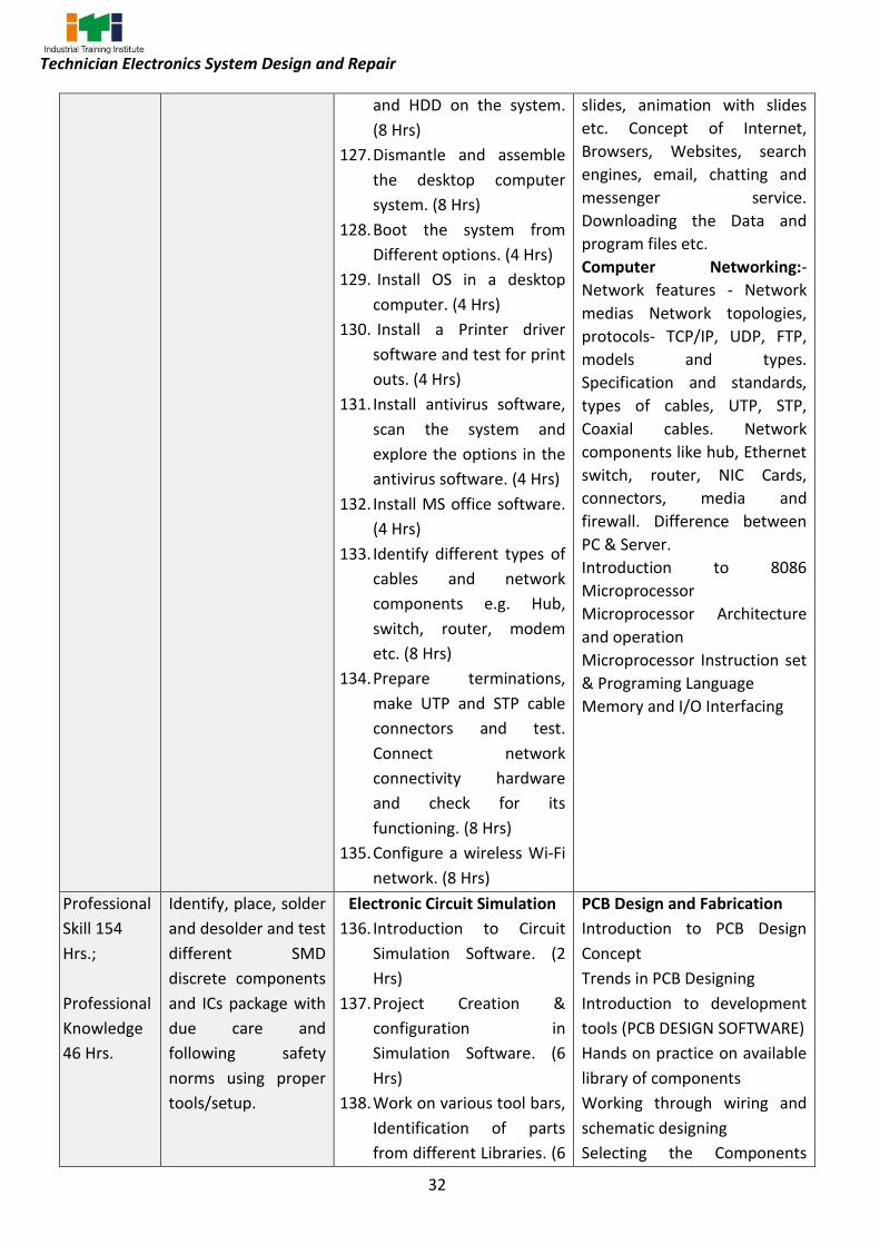
and HDD on the system.
(8 Hrs)
127. Dismantle and assemble
the desktop computer
system. (8 Hrs)
128. Boot the system from
Different options. (4 Hrs)
129. Install OS in a desktop
computer. (4 Hrs)
130. Install a Printer driver
software and test for print
outs. (4 Hrs)
131. Install antivirus software,
scan the system and
explore the options in the
antivirus software. (4 Hrs)
132. Install MS office software.
(4 Hrs)
133. Identify different types of
cables and network
components e.g. Hub,
switch, router, modem
etc. (8 Hrs)
134. Prepare terminations,
make UTP and STP cable
connectors and test.
Connect network
connectivity hardware
and check for its
functioning. (8 Hrs)
135. Configure a wireless Wi-Fi
network. (8 Hrs)
slides, animation with slides
etc. Concept of Internet,
Browsers, Websites, search
engines, email, chatting and
messenger service.
Downloading the Data and
program files etc.
Computer Networking:-
Network features - Network
medias Network topologies,
protocols- TCP/IP, UDP, FTP,
models and types.
Specification and standards,
types of cables, UTP, STP,
Coaxial cables. Network
components like hub, Ethernet
switch, router, NIC Cards,
connectors, media and
firewall. Difference between
PC & Server.
Introduction to 8086
Microprocessor
Microprocessor Architecture
and operation
Microprocessor Instruction set
& Programing Language
Memory and I/O Interfacing
Professional
Skill 154
Hrs.;
Professional
Knowledge
46 Hrs.
Identify, place, solder
and desolder and test
different SMD
discrete components
and ICs package with
due care and
following safety
norms using proper
tools/setup.
Electronic Circuit Simulation
136. Introduction to Circuit
Simulation Software. (2
Hrs)
137. Project Creation &
configuration in
Simulation Software. (6
Hrs)
138. Work on various tool bars,
Identification of parts
from different Libraries. (6
PCB Design and Fabrication
Introduction to PCB Design
Concept
Trends in PCB Designing
Introduction to development
tools (PCB DESIGN SOFTWARE)
Hands on practice on available
library of components
Working through wiring and
schematic designing
Selecting the Components

33
Technician Electronics System Design and Repair
Hrs)
139. Prepare a Schematic of
simple digital electronic
circuits using the
software. (6 Hrs)
140. Simulate & Test the digital
circuit. (6 Hrs)
141. Prepare a Schematic of
simple Analog electronic
circuits using the
software. (6 Hrs)
142. Simulate and test the
analog Circuit. (6 Hrs)
143. Processing a Design- Cross
Reference, Bill of Material,
Design Rule Check. (6Hrs)
144. Design and simulation of
Electronic system
Application. (6 Hrs)
PCB Design and Fabrication
145. Getting familiar with PCB
editor Design
Environment. (6 hrs)
146. Schematic design
modification for PCB
design and netlist
creation. (6 Hrs)
147. Design of Simple Board. (6
Hrs)
148. Perform Component
placement & Routing
plans. (6 Hrs)
149. Generate the 3D
Mechanical CAD View for
Board Design. (8 Hrs)
150. Gerber file Generation for
the Electronic System
Application. (8 hrs)
151. Prepare PCB for
transferring the track of
application developed
using simple etching
process. (6 Hrs)
Footprints as per design
Picking and placing the
Component
Making New Footprints
Assigning Footprint to
components
Introduction to Board
design: Board Basics, Basic
building blocks of
PCB, Overview of design flow
Introduction of PCB:
Definitions of PCB, PCB design,
PCB design tools, Introduction
to basic electronic
components, Process of PCB
designs
PCB Basic
Principle: Specification and
classification of
PCBs Techniques of layout
design Artwork generation
Methods - manual and
CAD General design factor for
digital and analog circuits ,
Layout and Artwork making
Schematic
Starting a project Working of
design tools Schematic
drawing from circuit Placing,
editing, and connecting parts
and electrical symbols, Symbol
Creation
Layout Design
Components placing Details of
layers Routing guidelines,
Gerber file generation
PCB Fabrication Techniques-
Chemical and Mechanical

34
Technician Electronics System Design and Repair
152. Perform Component
mounting, soldering and
Testing the final product
in PCB. (6 Hrs)
153. Identification of 2, 3, 4
terminal SMD
components. (4 Hrs)
154. De-solder the SMD
components from the
given PCB. (4 Hrs)
155. Solder the SMD
components in the same
PCB. (4 Hrs)
156. Check for cold continuity
of PCB. (4 Hrs)
157. Identify various
connections and setup
required for SMD
Soldering station. (4 Hrs)
158. Identify crimping tools for
various IC packages. (4
Hrs)
159. Make the necessary
settings on SMD soldering
station to solder various
ICs of different packages
(at least four) by choosing
proper crimping tools. (4
Hrs)
160. Make the necessary
settings on SMD soldering
station to de-solder
various ICs of different
packages (at least four) by
choosing proper crimping
tools. (4 Hrs)
161. Checked and Repair
Printed Circuit Boards
single, Double layer, and
important tests for PCBs.
(4 Hrs)
162. PCB Designing of Basic
and Analog Electronic

35
Technician Electronics System Design and Repair
Circuits. (4 Hrs)
163. PCB Designing of Power
Supplies. (4 Hrs)
164. PCB Designing of Different
Sensor modules. (4 Hrs)
165. PCB Designing of
Electronics Projects. (4
Hrs)
166. PCB Designing of
Embedded Projects. (6
Hrs)
167. Printing the Design. (2 hrs)
168. Eaching. ( 4 Hrs)
169. Drilling. (4 Hrs)
170. PCB file Generation. (4
Hrs)
171. Soldering and
Desoldering. (4 Hrs)
172. Component Mounting. (2
Hrs)
173. PCB and Hardware
Testing. (2 Hrs)
Project work / Industrial visit/Revision/Examination

36
Technician Electronics System Design and Repair
Syllabus for Technician Electronics System Design & Repair Trade
SECOND YEAR
Duration Reference
Learning Outcome
Professional Skills
(Trade Practical)
With Indicative Hours
Professional Knowledge
(Trade Theory)
Professional
Skill 90 Hrs.;
Professional
Knowledge
30 Hrs.
Develop code by
using C
programming
language following
proper syntax.
174. Execute simple C
programme to convert the
temperature in degree
Celsius to degree
Fahrenheit. (7 Hrs)
175. Execute a C program to
perform addition,
subtraction, multiplication
and division of two
numbers. (7 Hrs)
176. Execute To interchange the
numeric values of two
variables. (7 Hrs)
177. Execute To find the sum
and average of 3 real
numbers. (7 Hrs)
178. Execute To check a given
number is Even or Odd. (7
Hrs)
179. Execute To find the sum of
digits of a number. (7 Hrs)
180. Execute To reverse the
given integer and check
whether it is a palindrome
or not. (7 Hrs)
181. Write a program to play
with patterns. (7 Hrs)
182. To accept 10 numbers and
make the average of the
numbers using one
dimensional array. (7 Hrs)
183. To arrange N numbers in
ascending order and
descending order. (7 Hrs)
184. Find out the length of a
string. (7 Hrs)
C- Programming
Introduction to C language and
advantages
Program structure, basic
syntax, data types, variables
constants storage classes,
arithmetic and logical
operators, Control statements
and loops Functions and
Arrays. Strings, input, output,
pre-processor directives,
header file.

37
Technician Electronics System Design and Repair
185. To find the summation of
three numbers using the
function. (7 Hrs)
186. To find the maximum
among N numbers using
the function. (functions
with arguments and return
value). (6 Hrs)
Professional
Skill 104 Hrs.;
Professional
Knowledge
42 Hrs.
Identify and test
Architecture, Pin
description
programming
model and
programming of
8051
Microcontroller.
187. Identify various ICs & their
functions on the given
Microcontroller Kit. (7 hrs)
188. Practice various functions
of Keil software. (7 Hrs)
189. Write an assembly
language program to add,
subtract, multiply, divide
16 bit data by
microcontroller. (10 Hrs)
190. Interfacing simple switch
and LED to I/O ports to
switch on/off LED with
respect to switch status.
(10 Hrs)
191. Perform the initialization of
timer register, load & turn
on a LED with delay using
Timer. (10 hrs)
192. Write a Program for
interfacing seven segment
LED display and test it. (10
Hrs)
193. Write a program to
transmit a character to a
serial window at given
baud rate. (10 Hrs)
194. Demonstrate for
interfacing of Matrix
keyboard and test it. (10
Hrs)
195. Demonstrate for interface
a LCD display. (10 Hrs)
196. Demonstrate for
interfacing 8 bit ADC and
8051 Microcontroller
Introduction to micro
controller, comparison of
micro processor and micro
controller, Evaluation of
Microcontroller. Different
variants of 8051 & their
resources.
8051 Architecture- Registers,
Pin diagram, I/O ports
functions, Internal Memory
organization. External Memory
(ROM & RAM) interfacing.
8051 Instruction Set:
Addressing Modes, Data
Transfer instructions,
Arithmetic instructions, Logical
instructions, Branch
instructions, Bit manipulation
instructions.
8051 Stack, I/O Port
Interfacing and Programming:
8051 Stack, Stack and
Subroutine instructions.
8051 Timers and Counters –
Operations.
8051 Serial Communication-
Basics of Serial Data
Communication, RS-232
standard, 9 pin RS232 signals,
8051 Interrupts.
8051 Interfacing Applications:
LED, 7-segment display, LCD,
Keyboard, ADC and DAC.

38
Technician Electronics System Design and Repair
test it. (10 Hrs)
197. Demonstrate for
interfacing 8 bit DAC and
test it. (10 Hrs)
Professional
Skill 64 Hrs.;
Professional
Knowledge
20 Hrs.
Select and Test
Architecture, Pin
description
programming
model and
programming of
real time PIC
Microcontroller
198. Identify various ICs & their
functions on the given PIC
Microcontroller Kit. (6 hrs)
199. Practice various functions
of MPLAB simulation
software. (8 Hrs)
200. Write an assembly
language program to add,
subtract, multiply, divide
16 bit data by
microcontroller. (6 Hrs)
201. Interfacing simple switch
and LED to I/O ports to
switch on/off LED with
respect to switch status. (8
Hrs)
202. Perform the initialization of
timer register, load & turn
on a LED with delay using
Timer. (6 hrs)
203. Write a Program for
interfacing seven segment
LED display and test it. (6
Hrs)
204. Write a program to
transmit a character to a
serial window at given
baud rate. (6 Hrs)
205. Demonstrate for interface
a LCD display. (6 Hrs)
206. Write a program to
Interface stepper motor
with PIC18. (6Hrs)
207. Write a program to
Interface DC motor with
PIC18. (6 Hrs)
PIC Microcontroller
History, Features and
Architecture
Overview of the PIC18
Family.PIC18 PIN
connection.PIC18
Configuration Registers. The
WREG Register in PIC18.The
PIC18 File Register and access
Bank. Use of Instructions with
the Default Access Bank. PIC18
Status Register. PIC18 Data
Format and Directives. The
Program Counter and Program
ROM Space in the PIC18. RISC
Architecture in the PIC18
Classification of Instructions
set Arithmetic Instructions.
Arithmetic Operations, Logic
and Compare Instructions.
Rotate Instruction and Data
Serialization. Branch
Instructions and Looping. Call
Instructions and Stack PIC18
Time Delay and Instruction
Pipeline.
PIC Timers and Counters –
Operations. PIC Serial
Communication, PIC
Interrupts.
PIC18 Interfacing Applications:
LCD, Keyboard, ADC, DAC, DC
motor, Stepper Motor
Professional
Skill 62 Hrs.;
Select various
sensors/ actuators
and construct
208. Identification of various
sensors (Proximity Sensors,
inductive sensor, capacitive
Sensors & actuators Basics of passive and active
transducers. Role, selection

39
Technician Electronics System Design and Repair
Professional
Knowledge
18 Hrs.
different circuits
used in embedded
system.
sensor, magnetic sensor
etc.,) (06 hrs)
209. Construct simple control
circuit using Proximity
sensor and reed switch and
limit switch. (04 hrs)
210. Test the working of various
sensors (Reflex
Photoelectric Sensors,
ultrasonic sensor. reed
switch limit switch
Temperature Sensors,
Level Control( 6 Hrs)
211. Perform Logical operation
of sensors (06 hrs)
212. Interface Sensors and
Electrical Actuators. (06
hrs)
213. Practice Measurement of
Load using Load cell. (02
hrs)
214. Measure Displacement
using LVDT. (03 hrs) ( 8 Hrs)
215. Construct an open loop
control system for
pressure, temperature,
flow and level. (12 hrs)
216. Construct closed loop
control system for
pressure, temperature,
flow and level. (12 hrs)
and characteristics. Sensor
voltage and current formats.
Thermistors/ Thermocouples -
Basic principle, salient
features, operating range,
composition, advantages and
disadvantages.
Strain gauges/ Load cell –
principle, gauge factor, types
of strain gauges.
Inductive/ capacitive
transducers - Principle of
operation, advantages and
disadvantages.
Principle of operation of LVDT,
advantages and
disadvantages.
Proximity sensors –
applications, working
principles of eddy current,
capacitive and inductive
proximity sensors
Professional
Skill 64 Hrs.;
Professional
Knowledge
20 Hrs.
Plan and Carry out
embedded project
development cycle
217. Write an Assembly
Language Program for
interfacing Traffic light
control and test it.
218. Design a calculator to
perform a arithmetic
operations.
219. Perform DC motor speed
control using PWM with
PIC18.
220. Perform the use of a Timer
as an Event counter to
Embedded System Design Embedded systems, processor
embedded into a system,
embedded hardware units and
devices in a system,
Embedded software in a
system, examples of
embedded systems
Design process in embedded
system, design process and
design examples
Classification of embedded

40
Technician Electronics System Design and Repair
count external events.
221. Develop a project work by
interfacing various sensor
and relay with PIC
Microcontroller.
(Trainers may encourage the trainees to develop any two project using Microcontroller/PIC other than the above like Smart Dustbin, Water level controller, weather monitoring, irrigation controller etc.,) ( 64 Hrs)
systems, skills required for an
embedded system designer.
Professional
Skill 48 Hrs.;
Professional
Knowledge
20 Hrs
Install, configure
and check the
architecture of
IoT, various IoT
applications & its
components from
real time IoT
environments
222. Study and identify different
of IoT Applications in Smart
City. (6 Hrs)
223. Study and identify different
of IoT Applications in Smart
Agriculture. (6 Hrs)
224. Study and identify different
of IoT Applications in Smart
Healthcare. (6 Hrs)
225. Study and identify different
of IoT Applications in Smart
Automotive.
(6 Hrs)
226. Identify & study IoT
components in Smart
Home System. (6 Hrs)
227. Identify &study IoT
components in smart
wearables. (6 Hrs)
228. Identify &study IoT
components in smart
Power Management. (6
Hrs)
229. Identify &study IoT
components in Industrial
IoT. (6 Hrs)
IoT Applications & its
Components
What is IoT, How does IoT
works, Difference between
Embeded device and IoT
device, IoT Architecture & its
Components, IoT applications
in various fields like Retail,
Manufacturing, Healthcare,
Logistics, infrastructure etc.
Professional
Skill 260 Hrs.;
Professional
Knowledge
Position
appropriate
control boards of
various type used
in application
230. Identify & study of pin
configuration of Node
MCU. (5 Hrs)
231. Installing software
(Arduino IDE) for
IoT Controllers &its
Programming
Concept of Prototype Boards,
List of open source prototype
boards (IoT controllers)

41
Technician Electronics System Design and Repair
96 Hrs. development and
its programming
NodeMCU, adding
nodeMCU board in IDE (6
Hrs)
232. Installing serial drivers,
Connecting Node MCU
with PC and selecting
NodeMCU in IDE. (5 Hrs)
233. Understanding setup &
loop functions of Arduino.
(5 Hrs)
234. Writing sample Hello world
code for NodeMCU in
Arduino IDE, uploading to
NodeMCU& using serial
monitor of IDE. (6 Hrs)
235. Write a code and upload to
NodeMCU to blink on
board LED with 1 sec
duration. (4 Hrs)
236. Write a code and upload to
NodeMCU to blink external
LED with 1 sec duration. (4
Hrs)
237. Write a code and upload to
NodeMCU to generate a
pattern on LED bank of
four number and run
application as standalone
(4 Hrs)
238. Building light intensity
reader circuit with
NodeMCU. (4 Hrs)
239. Build and operate a relay
circuit with NodeMCU. (4
Hrs)
240. Connecting Arduino Uno
with PC and configuring for
Arduino board. (3 Hrs)
241. Hello World display on
serial monitor from
Arduino. (3 Hrs)
242. Arduino basic functions:
pinMode, digitalRead,
available in the market,
Features, specifications &
applications of Node MCU.
Arduino Boards: Types,
specifications, features,
applications of each.
Arduino Uno: GPIO- analog
pins & digital pins
Arduino IDE, Arduino Program
structure, Arduino variables,
operators, Conditional
statements, Loops, Arrays,
Functions. Arduino Libraries.
Python Programming
Language: Introduction,
installation, programming
tools, applications.
Linux OS: Introduction, Tools,
Commands.
ARM processors: Introduction,
versions, architecture,
specifications, applications.
Raspberry Pi Boards: Types of
RPi, features, specifications
&applications. And GPIO
Overview of other boards:
CHIP, Adafruit Flora, Beagle
Boards, Banana Pi, Intel
Edison.

42
Technician Electronics System Design and Repair
analogRead. (4 Hrs)
243. (LED blinking using Arduino
digital pin. (4 Hrs)
244. Switch-LED interfacing with
Arduino. (4 Hrs)
245. Seven Segment display
interfacing with Arduino. (4
Hrs)
246. Arduino Library and Adding
external libraries to IDE. (4
Hrs)
247. LCD interfacing with
Arduino. (3 Hrs)
248. DC motor interfacing with
Arduino. (3 Hrs)
249. Stepper motor interfacing
with Arduino. (3 Hrs)
250. Servo motor interfacing
with Arduino. (3 Hrs)
251. Potentiometer interfacing
with Arduino. (3 Hrs)
252. Interface LDR with
Arduino. (3 Hrs)
253. Interface LM35 with
Arduino. (3 Hrs)
254. Interface Relay with
Arduino. (3 Hrs)
255. Python SW Installation on
windows. (3 Hrs)
256. Python path setup in
windows. (3 Hrs)
257. Python Hello world
Program & execution. (3
Hrs)
258. Exercises on Python
Variables & data types. (3
Hrs)
259. Exercises on Python
operators. (8 Hrs)
260. Exercises on python Inputs
& Outputs. (8 Hrs)
261. Exercises on Python
numbers &srtings. (8 Hrs)

43
Technician Electronics System Design and Repair
262. Exercises on python
conditional statements. (10
Hrs)
263. Exercises on python Loops.
(10 Hrs)
264. Exercises on python Lists.
(5 Hrs)
265. Exercises on python tuples
& Dictionaries. (8 Hrs)
266. Exercises on python
Functions. (12 Hrs)
267. Exercises on python
Classes. (8 Hrs)
268. Exercises on Date Time
Class. (6 Hrs)
269. Install Ubuntu in PC. (3 Hrs)
270. Linux Commands:
TTY,UNAME, DATE, CAL,
WHOAMI,MAN, PWD, LS,
TOUCH, MKDIR, CAT, RM,
RMDIR, CP, MV, WC, ECHO,
CLEAR, ALIAS, SUDO,
CHMOD, UMASK,
ADDUSER, PING,
HOSTNAME. (14 Hrs)
271. Installation & setup of
Raspbian OS on Raspberry
Pi. (9 Hrs)
272. Install python on Raspberry
Pi. (3 Hrs)
273. Working with Python on
Raspberry Pi. (12 Hrs)
274. Exercises on RPi GPIO
programming with LEDs &
switches. (6 Hrs)
275. Exercises on RPi Relay &
motor interfacing. (3 Hrs)
276. Exercises on display(s)
(LCD, OLED) interfacing
with RPi. (8 Hrs)
Professional
Skill 32 Hrs.;
Execute different
principles of
sensors used in IoT
277. Arduino/Raspberry Pi
programming of following
sensors:
IoT Sensors
Sensors: Introduction,
principles and applications of

44
Technician Electronics System Design and Repair
Professional
Knowledge
12 Hrs.
and its
programming
• Ultrasonic (3 Hrs)
• PIR & IR (3 Hrs)
• Alcohol (3 Hrs)
• LDR (3 Hrs)
• Gas (3 Hrs)
• DHT11, DHT22 (3 Hrs)
• Rain drop (3 Hrs)
• Soil moisture (3 Hrs)
• LM35 (3 Hrs)
• C02, Air pollution (3
Hrs)
• Photo detector (2 Hrs)
following sensors: Ultrasonic,
PIR, IR, Alcohol, LDR, Gas,
DHT11/22, rain drop, soil
moisture, LM35, CO2, Air
pollution & photo detector.
Professional
Skill 160 Hrs.;
Professional
Knowledge
60 Hrs.
Test and verify the principles of different IoT gateways & Protocols and its programming.
278. Exercises on NodeMCU,
Arduino & RPi with
USART/UART protocol. (10
Hrs)
279. Exercises on Arduino & RPi
with SPI interfacing
protocol. (7 Hrs)
280. Exercises on Arduino &RPi
with I2C protocol. (7 Hrs)
281. Configure ESP8266 with
PC. (5 Hrs)
282. Setup ESP8266 as
webserver. (7 Hrs)
283. Setup ESP8266 as access
point. (4 Hrs)
284. Interface ESP8266 module
with Arduino Uno. (5 Hrs)
285. Configure Bluetooth
Module with PC. (7 Hrs)
286. Interface Bluetooth
module with Node MCU. (4
Hrs)
287. Interface Bluetooth with
Arduino Uno. (4 Hrs)
288. Pair & Transfer data
between Node MCU and
Arduino by using Bluetooth
devices. (7 Hrs)
289. Pair & Transfer LM35
output temperature data
IoT Protocols & Gateways
IoT networks, protocol stacks
Wired Communication ( 8Hrs)
Protocols – UART, USART, I2C,
SPI
Wireless Communication
Protocols – Bluetooth, WiFi,
Overview of LPWAN (LoRa,
NBIoT)
Networking Protocols – OSI
Reference Model, TCP/IP
Application Protocols – HTTP,
MQTT, XMPP, AMQP.
IoT network architecture –
Client-Server vs Publish-
Subscribe
Concepts of IoT security
features.

45
Technician Electronics System Design and Repair
between RPi and Arduino
by using Bluetooth devices.
(6 Hrs)
290. Configure Zigbee with PC.
(4 Hrs)
291. Configure Zigbee modules
as Master & slave. (7 Hrs)
292. Transmit raw data from
Master to slave using
zigbee modules. (7 Hrs)
293. Interface zigbee module to
Arduino. (6 Hrs)
294. Interface Zigbee and
configure Arduino Uno as
master and Arduino mega
as slave and transmit the
light intensity. (6 Hrs)
295. Transmit LDR data from
Arduino to RPi. (6 Hrs)
296. Construct 3 stage network
(wifi to Bluetooth network)
by using NodeMCU-RPi-
Arduino and transmit
Humidity and temperature
information from
NodeMCU to Arduino via
RPi. (15 Hrs)
297. Construct 3 stage network
(wifi to zigbee network) by
using NodeMCU-RPi-
Arduino and transmit
Humidity and temperature
information from
NodeMCU to Arduino via
RPi. (15 Hrs)
298. Configure NodeMCU as
MQTT publisher. (5 Hrs)
299. Configure NodeMCU as
MQTT subscriber. (5 Hrs)
300. Configure RPi as MQTT
publisher. (5 Hrs)
301. Configure NodeMCU as
MQTT subscriber. (6 Hrs)
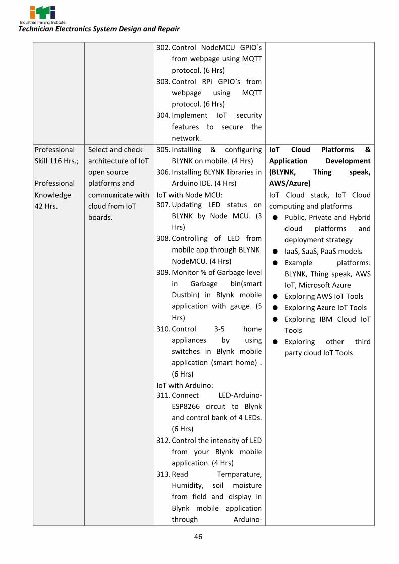
46
Technician Electronics System Design and Repair
302. Control NodeMCU GPIO`s
from webpage using MQTT
protocol. (6 Hrs)
303. Control RPi GPIO`s from
webpage using MQTT
protocol. (6 Hrs)
304. Implement IoT security
features to secure the
network.
Professional
Skill 116 Hrs.;
Professional
Knowledge
42 Hrs.
Select and check
architecture of IoT
open source
platforms and
communicate with
cloud from IoT
boards.
305. Installing & configuring
BLYNK on mobile. (4 Hrs)
306. Installing BLYNK libraries in
Arduino IDE. (4 Hrs)
IoT with Node MCU: 307. Updating LED status on
BLYNK by Node MCU. (3
Hrs)
308. Controlling of LED from
mobile app through BLYNK-
NodeMCU. (4 Hrs)
309. Monitor % of Garbage level
in Garbage bin(smart
Dustbin) in Blynk mobile
application with gauge. (5
Hrs)
310. Control 3-5 home
appliances by using
switches in Blynk mobile
application (smart home) .
(6 Hrs)
IoT with Arduino: 311. Connect LED-Arduino-
ESP8266 circuit to Blynk
and control bank of 4 LEDs.
(6 Hrs)
312. Control the intensity of LED
from your Blynk mobile
application. (4 Hrs)
313. Read Temparature,
Humidity, soil moisture
from field and display in
Blynk mobile application
through Arduino-
IoT Cloud Platforms &
Application Development
(BLYNK, Thing speak,
AWS/Azure)
IoT Cloud stack, IoT Cloud
computing and platforms
Public, Private and Hybrid
cloud platforms and
deployment strategy
IaaS, SaaS, PaaS models
Example platforms:
BLYNK, Thing speak, AWS
IoT, Microsoft Azure
Exploring AWS IoT Tools
Exploring Azure IoT Tools
Exploring IBM Cloud IoT
Tools
Exploring other third
party cloud IoT Tools

47
Technician Electronics System Design and Repair
WiFi.(smart agriculture). (6
Hrs)
314. Get notification to your
mobile via Blynk when your
IoT device goes offline. (6
Hrs)Tweet about air
pollution & CO2 level from
Your IoT device to your
Twitter Account. (smart
City) . (6 Hrs)
315. Creating & configuring
Thingspeak account. (3
Hrs)
316. Monitor Temparature &
Humidity in Blynk and
Thingspeak IoT platforms
from your hardware. (6
Hrs)
317. Control home appliances
from google assistant with
Blynk and IFTTT. (5 Hrs)
318. IoT with Raspberry Pi:
319. Controlling LED bank form
RPi-3 and Blynk. (5 Hrs)
320. Temperature, pulse, and
ECG monitoring of a
patient on Things peak
mobile application. (smart
Health) . (13 Hrs)
321. CCTV monitoring of a
Campus by using RPi.
(Smart Campus). (30 Hrs)
Project work / Industrial visit/Revision/Examination

48
Technician Electronics System Design and Repair
SYLLABUS FOR CORE SKILLS
1. Workshop Calculation & Science is common for 1st & 2nd year for all engineering courses (80 Hrs + 80 Hrs)
2. Engineering Drawing of first year is common for all engineering trades. (80 Hrs)
3. Engineering Drawing of second year (Common for Group-II of Engineering Drawing) (Electrical, Electronics & IT Trade Group) (80 Hrs)
4. Employability Skills is common for all CTS trades (160 Hrs + 80 Hrs)
Learning outcomes, assessment criteria, syllabus and Tool List of Core Skills subjects which is common for a group of trades, provided separately in www.bharatskills.gov.in

49
Technician Electronics System Design and Repair
List of Tools & Equipment
Technician Electronics System Design and Repair (for batch of 24 candidates)
S No. Name of the Tools
and Equipment Specification Quantity
A. TRAINEES TOOL KIT (For each additional unit trainees tool kit Sl. 1-16 is required additionally)
1. Connecting screwdriver 10 X 100 mm 12 Nos.
2. Neon tester 500 V. 500 V 24+1 Nos.
3. Screw driver set Set of 7 12 Nos.
4. Insulated combination pliers 150 mm 8 Nos.
5. Insulated side cutting pliers 150 mm 10 Nos.
6. Long nose pliers 150 mm 8 Nos.
7. Soldering iron 25-Watt, 240 Volt 24+1 Nos.
8. Electrician knife 100 mm 8 Nos.
9. Tweezers 150 mm
24+1 Nos.
10. Tweezer Smart SMD tester tweezer resistance capacitance, diode test auto power off low battery indication.
01 No.
11. Digital Multimeter (3 3/4 digit) ,4000 Counts Digital Multimeter with 4000 counts, Large Display with Auto/Manual and can measure DCV- 1000V-ACV-750V, DC & AC A – 20A, Resistance 40MΩ, Capacitance up to 200µF , Capacitance and Frequency -30 MHz
12 Nos.
12. 6 1/2 Digit Digital Multimeter Measurement Functions: DC &AC Voltage, DC&AC Current, 2-wire, 4-wire Resistance, CAP, Diode, Connectivity, Frequency, Period, Any Sensor. Temperature: RTD, THERM,TC (B/E/J/K/N/R/S/T) PC Interface USB Host, USB Device, LAN(LXI-C) Measurement Speed 10k readings/sec
02 No.
ANNEXURE-I

50
Technician Electronics System Design and Repair
13. 9KHz to 3.2GHz Spectrum Analyzer with LISN and Sniffer Probe for EMI-EMC Testing
Frequency Range 9 kHz to 3.2 GHz Resolution Bandwidth (-3 dB): 10 Hz to 1 MHz Built in tracking generator Min. -148 dBm DANL Display 8” TFT or more PC Interface: USB Host & Device, LAN(LXI), near field probe, EMI Pre-compliance Software, EMI filter and quasi peak detector and 2 Line LISN 300Vrms, 16A as per CISPR16-1-2.
1 No.
14. Soldering Iron Changeable bits 15-Watt, 240 Volt 12 Nos.
15. De-soldering pump electrical heated, manual operators
230 V, 40 W 12 Nos.
16. Continuity tester 24+1 Nos.
B. SHOP TOOLS, INSTRUMENTS – For 2 (1+1) units no additional items are required
17. Steel rule graduated both in Metric and English Unit
300 mm 4 Nos.
18. Precision set of screw drivers T5, T6, T7 2 Nos.
19. Tweezers – Bend tip 2 Nos.
20. Steel measuring tape 3 meter 4 Nos.
21. Tools makers vice 100mm (clamp) 1 No.
22. Tools maker vice 50mm (clamp) 1 No.
23. Crimping tool (pliers) 7 in 1 2 Nos.
24. Magneto spanner set 8 Spanners 2 Nos.
25. File flat bastard 200 mm 2 Nos.
26. File flat second cut 200 mm 2 Nos.
27. File flat smooth 200 mm 2 Nos.
28. Plier - Flat Nose 150 mm 4 Nos.
29. Round Nose pliers 100 mm 4 Nos.
30. Scriber straight 150 mm 2 Nos.
31. Hammer ball pen 500 grams 1 No.
32. Allen key set (Hexagonal -set of 9)
1 - 12 mm, set of 24 Keys 1 No.
33. Tubular box spanner Set - 6 - 32 mm 1 set.
34. Magnifying lenses 75 mm 6 Nos.
35. Hacksaw frame adjustable 300 mm 2 Nos.
36. Chisel - Cold - Flat 10 mm X 150 mm 1 No.

51
Technician Electronics System Design and Repair
37. Scissors 200mm 4 Nos.
38. Handsaw 450mm Hand Saw - 450 mm 1 No.
39. Hand Drill Machine Electric with Hammer Action
13 mm 3 Nos.
40. First aid kit 1 No.
41. Bench Vice Bench Vice - 125 mm 1 No. each Bench Vice - 100 mm
Bench Vice - 50 mm
C. List of Equipment 42. Dual DC regulated power
supply 30-0-30 V, 2 Amps Dual DC 0 - 30 V,2 A , current limit 100 mA - 2 A, Line & Load regulation ± (0.05 % + 10 mV) , ripple < 1mVrms , 3 digit display for voltage & current
2 Nos.
43. Multiple Output DC regulated power supply
0-30V, 2 Amps, + 15V Dual Tracking ,5V/5A, Display digital, Load & Line Regulation: ± (0.05 %+100 mV), Ripple & Noise <= 1 mVrms constant Voltage & Current operation
2 Nos.
44. DC Regulated Variable Programmable DC Power Supply
0-30V/3A 0-30V/3A with numeric keypad, PC interface and LCD for Voltage, Current & Power
2 Nos.
45. LCR meter (Digital) Handheld LCR Meter Primary parameters: L / C / R / Z Secondary parameters: D / Q / R Display LCD 4000 Count for primary parameter Inductance Range: 0.00μH - 1000.0H Capacitance Range: 0.00pF - 20.000mF Resistance Range: 0.0000Ω- 10.000MΩ Basic Accuracy : 0.25% Frequency 100Hz,120Hz,1kHz,10kHz
1 No.
46. 100MHz Two Channel Digital Storage Oscilloscope
With more than 20Mpt memory Real time Sampling 1GSa/sec , having LAN Interface, RS232/UART, I2C ,SPI trigger & decoding plus math functions like differentiation, integration, abs, AND,OR,NOT etc..
02 Nos.
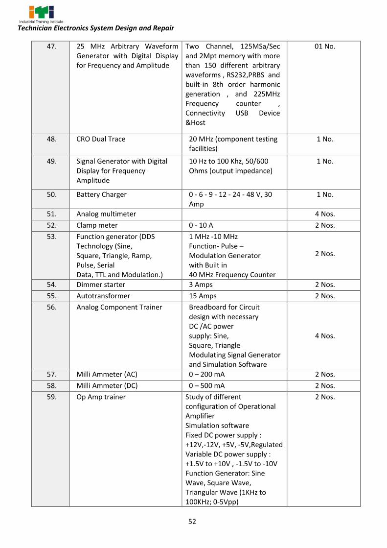
52
Technician Electronics System Design and Repair
47. 25 MHz Arbitrary Waveform Generator with Digital Display for Frequency and Amplitude
Two Channel, 125MSa/Sec and 2Mpt memory with more than 150 different arbitrary waveforms , RS232,PRBS and built-in 8th order harmonic generation , and 225MHz Frequency counter , Connectivity USB Device &Host
01 No.
48. CRO Dual Trace 20 MHz (component testing facilities)
1 No.
49. Signal Generator with Digital Display for Frequency Amplitude
10 Hz to 100 Khz, 50/600 Ohms (output impedance)
1 No.
50. Battery Charger 0 - 6 - 9 - 12 - 24 - 48 V, 30 Amp
1 No.
51. Analog multimeter 4 Nos.
52. Clamp meter 0 - 10 A 2 Nos.
53. Function generator (DDS Technology (Sine, Square, Triangle, Ramp, Pulse, Serial Data, TTL and Modulation.)
1 MHz -10 MHz Function- Pulse – Modulation Generator with Built in 40 MHz Frequency Counter
2 Nos.
54. Dimmer starter 3 Amps 2 Nos.
55. Autotransformer 15 Amps 2 Nos.
56. Analog Component Trainer Breadboard for Circuit design with necessary DC /AC power supply: Sine, Square, Triangle Modulating Signal Generator and Simulation Software
4 Nos.
57. Milli Ammeter (AC) 0 – 200 mA 2 Nos.
58. Milli Ammeter (DC) 0 – 500 mA 2 Nos.
59. Op Amp trainer Study of different configuration of Operational Amplifier Simulation software Fixed DC power supply : +12V,-12V, +5V, -5V,Regulated Variable DC power supply : +1.5V to +10V , -1.5V to -10V Function Generator: Sine Wave, Square Wave, Triangular Wave (1KHz to 100KHz; 0-5Vpp)
2 Nos.

53
Technician Electronics System Design and Repair
Op Amp IC: IC uA741 (2 Nos..), and Resistance (SMD), Capacitance and Variable Resistance, Diode Bank.
60. Digital IC Trainer Breadboard for Circuit design with necessary DC Power Supply, Graphical LCD, Clock Frequency 4 different steps, Data Switches: 8 Nos., LED Display: 8 Nos.. (TTL), Seven Segment Display, Teaching Simulation Software
4 Nos.
61. Digital IC Tester 1 No.
62. Digital and Analog Bread Board Trainer
DC/AC Power Supply, Sine/ Square/ TTL Generator Data Switches, LED indication, LED Display: 8 in Nos. Simulation/Teaching Content through software
6 Nos.
63. Rheostats various values and ratings
2 Nos. each
64. Power Electronics Trainer with at least 6 no’s of application board MOSFET Characteristics SCR Characteristics SCR Lamp Flasher SCR Alarm Circuit
POWER ELECTRONICS TRAINER DC Power Supply: ±5V/500mA; ±12V/500mA; +15V/250mA; ±35V/250mA AC power Supply: 18V-0V-18V; 0V-15V , circuit with Frequency range: 30Hz to 900Hz variable; Amplitude: 12V; PWM control of G1, G2, G3 & G4; Duty cycle control of Gate signal is 0 to 100% and application boards MOSFET Characteristics, SCR Characteristics, SCR Lamp Flasher, SCR Alarm Circuit, Series Inverter, ingle Phase PWM Inverter
4 Nos.
65. Computers in the assembled form (including cabinet, motherboards, HDD, DVD, SMPS, Monitor, KB, Mouse, LAN card, Blu-Ray drive and
4 Nos.

54
Technician Electronics System Design and Repair
player), MS Office education version.
66. Laptops latest configuration 1 No.
67. Laser jet Printer 1 No.
68. INTERNET BROADBAND CONNECTION
1 No.
69. Electronic circuit simulation software with 6 user licenses
Circuit Design and Simulation Software with PCB Design with Gerber and G Code Generation, 3D View of PCB, Breadboard View, Fault Creation and Simulation.
1 No.
70. Different types of electronic and electrical cables, connectors, sockets, terminations.
As required
71. Different types of Analog electronic components, digital ICs, power electronic components, general purpose PCBs, bread board, MCB, ELCB
As required
72. Soldering & De soldering Station
SMD Soldering & De-soldering, Station Digitally Calibrated, Temperature Control SMD, Soldering & De-soldering, Power Consumption 60 Watts, I/P Voltage 170 to 270 V, De-soldering 70-Watt, Temperature Range 180 to, 480º Centigrade, Power Consumption 270 Watts, Hot Air Temperature 200 to 480º C
2 No.
73. SMD Technology Kit SMD component identification board with SMD components Resistors, Capacitors, Inductors, Diodes, Transistors & IC’s packages. Proto boards with readymade solder pads for various SMD Components. SMD Soldering Jig and Wall chart
1 No
74. DOL starter 1 No.
75. AC Motor Trainer Kit ¼ HP motor Single Phase
1 No.

55
Technician Electronics System Design and Repair
Contactors Relays MCB DOL Starter
76. Microcontroller kits (8051) along with programming software (Assembly level Programming)
Core 8051, ready to run programmer for AT89C51/52 & 55, programming modes Key Pad and PC circuits. Detailed learning content through simulation Software.
4 Nos.
77. Application kits for Microcontrollers 6 different applications
a) Input Interface: 4x4 Matrix Keypad, ASCII Key PAD, Four Input Switch b) Display Module 16X2 LCD, Seven Segment, LED Bar Graph c) ADC/DAC Module with most popular DC/DAC0808 d) PC Interface: RS232 &USB e) Motor Drive: DC, Servo, Stepper f) DAQ: Data Acquisition to sense different sensors signals
1 set
78. Sensor Trainer Kit Containing Following Sensors a) Thermocouple b) RTD c) Load Cell/ Strain Gauge d) LVDT e) Smoke Detector Sensors f) Speed Sensor g) Limit Switch h) Photosensors i) Opto-coupler j) Proximity Sensor
Graphical touch LCD with inbuilt processor for viewing the output waveforms, In built DAQ, and standard processing circuits like Inverting, Non-Inverting, Power, Current, Instrumentation Differential Amplifier, F/V,V/F,V/I,I/V Converter, Sensors :RTD,NTC Thermistor,LM35 Thermocouple, Gas (Smoke) Sensor, Load cell, LVDT Sensor, Speed Sensor
2 Nos.
79. Various analog and digital ICs useful for doing project works mentioned in the digital and analog IC applications modules
As required
80. Different types of electronic and electrical cables, connectors, sockets, terminations.
As required
81. Seven segment DPM trainer 6 Nos.
82. LCD based DPM 6 Nos.

56
Technician Electronics System Design and Repair
83. SMPS of different make 4 Nos.
84. SMPS Trainer Wide variation of Input AC Voltage 90 to 230 VAC, 50/60Hz. Ouput: +12V,-12V,+5V Regulated DC Switching Transformer 300V DC switching at 125KHz Output : 30V approx.
2 Nos.
85. PCB making machine PCB Prototype machine with auto resuming operation facility, auto bit protection, auto depth sensing, start-stop and play-pause. orking area (XYZ) 220x200x15 mm Min drill hole Size 0.3 mm, Min cutting trace/space : 0.15 mm (6 mil)X/Y travel speed 40 mm/sec ,X/Y Resolution 0.06 mm ,Spindle speed (RPM) 25000 Tool change Manual Change Tool holder 1/8 inch
1 No.
86. FR4 Grade PCBs As required
87. Different types of Analog electronic components, digital ICs, power electronic components, general purpose PCBs, bread board, MCB, ELCB
As required
88. PCB Drill Machine 1 No.
89. RAW MATERIAL FOR PCB DEVELOPMENT
AS Required
90. Desktop computer Latest configuration with preloaded OS and MS office
12 Nos.
91. Laptop Latest configuration with preloaded OS and MS office
1 No.
92. Microcontroller 8051 Development Board(consumables) with suitable IDE software
8051 associated circuits with on board LEDs (8), push buttons (8), Potentiometer, buzzer, ADC, relay driver, DC motor driver, stepper motor driver, 7 segment display (2), 4X4 keypad, LCD display, RTC, LM35, PIR sensor.
8 Nos.
93. PICF18 Microcontroller Development board with suitable IDE software (consumables)
PIC associated circuits with on board LEDs (8), push buttons (8), Potentiometer, buzzer, ADC, relay driver, DC motor
8 Nos.

57
Technician Electronics System Design and Repair
driver, stepper motor driver, 7 segment display (2), 4X4 keypad, LCD display, RTC, LM35, PIR sensor.
94. Different Microcontroller/Processor Training and Development Platform for AVR, PIC, ARM and Arduino.
MCU PIC16F877A, 4MHz, Ready to run programmer will program PIC Devices, USB Port MCU ATMEGA8515 ,8MHz, Ready to run programmer will program ATMEGA series microcontroller, USB Port MCU LPC2148, 12MHz, LED 8Nos, ADC 10 bit 10Nos, DAC 10bit, PWM, Sensor LM35 , Display 16X2 LCD Display , Motor Drive: L293D 600mA (5-12V),Programmer USB Interface. Microcontroller ATmega328p, 16MHz, Digital I/O Pins: 14 (of which 6 provide PWM output), Flash Memory: 16KB (of which 2KB used by boot loader) Each platform should have Bread DC Power Supplies +12V, -12V, +5V & - 5V, Breadboard to make circuits
1 No.
95. Different Modules for controllers
Zigbee Bluetooth RFID Finger Print GSM GPS Display LCD, Seven Segment, KED Matrix, LED Input Devices ASCII Keyboard, Hexa Keypad and Switch Motors DC , Stepper, Servo
1 No.
96. Sensor Trainer Kit Containing following Sensors 1. Thermocouple 2. RTD 3. Load Cell/ Strain Gauge 4. LVDT 5. Smoke Detector Sensors 6. Speed Sensor 7. Limit Switch 8. Photo sensors 9. Opto-coupler 10. Proximity
Graphical touch LCD with inbuilt processor for viewing the output waveforms, In built DAQ, and standard processing circuits like Inverting, Non – Inverting, Power, Current, Instrumentation Differential Amplifier, F/V, V/F, V/I, I/V
4 Nos.

58
Technician Electronics System Design and Repair
Sensor
Converter, Sensors(consumables): RTD, NTC Thermistor, LM35 Thermocouple, Gas (Smoke) Sensor, Load cell, LVDT Sensor, Speed Sensor
97. Electronic Circuit simulation software suite (with PCB design and Mechanic Design)
12 licenses
98. IoT Smart City Trainer with 3-5 applications. [modular trainer] (These Trainers can also be assembled by instructors with consumables, for which a training can be proposed at NSTIs)
With smart parking station, garbage control, dynamic traffic control, water management, smart lighting,
1 No.
99. IoT Smart Agriculture Trainer with 3-5 applications. [modular trainer] (These Trainers can also be assembled by instructors with consumables, for which a training can be proposed at NSTIs)
1 No.
100. IoT Smart Health care Trainer with 2-4 applications. [modular trainer] (These Trainers can also be assembled by instructors with consumables, for which a training can be proposed at NSTIs)
1 No.
101. IoT Smart Home Trainer with 3-5 applications. [modular trainer] (These Trainers can also be assembled by instructors with consumables, for which a training can be proposed at NSTIs)
1 No.
102. IoT Smart wearables Trainer with 3-5 applications. [modular trainer] (These Trainers can also be assembled by instructors with consumables, for which a training can be proposed at NSTIs)
1 No.
59
Technician Electronics System Design and Repair
103. IoT Smart grid Trainer with 2-3 applications. [modular trainer] (These Trainers can also be assembled by instructors with consumables, for which a training can be proposed at NSTIs)
1 No.
104. IoT Smart Bike Trainer with 2-3 applications. [modular trainer] (These Trainers can also be assembled by instructors with consumables, for which a training can be proposed at NSTIs)
1 No.
105. Industrial IoT Trainer with 2-3 applications. [modular trainer] (These Trainers can also be assembled by instructors with consumables, for which a training can be proposed at NSTIs)
1 No.
106. Embedded & IoT Simulating software
VSM for 8051, PIC, IoT Simulator for Arduino, RPi with cloud tools support.
13 Users
107. Node MCU (ESP) [Consumable] 24 Nos.
108. Arduino Uno Boards [Consumable]
24 Nos.
109. Arduino Nano Boards [Consumable]
10 Nos.
110. Raspberry Pi 3+/4 Boards 10 Nos. each
111. Universal IO board for IoT compatible with NodeMCU, Arduino, RPi.
LED (8 Nos.), switches, buzzer, LCD, OLED, segment display, DC motor, Servo motor, stepper motor, relays 5V/12V (4 Nos.) with required power supplies.
12 Nos.
112. Universal IoT Sensor Board compatible with NodeMCU, Arduino, RPi.
LDR, LM35, PIR, IR, Ultrasonic, Alchoholic, Rain drop, DHT11/22, CO2, air pollution, soil moisture, & photo detector
12 Nos.
113. Universal IoT protocol Board compatible with NodeMCU, Arduino, RPi.
USART/UART, SPI, I2C, CAN 10 Nos.
114. Bluetooth interface board compatible with NodeMCU, Arduino, RPi.
12 Nos.
115. WiFi (ESP8266) interface board 12 Nos.
60
Technician Electronics System Design and Repair
compatible with NodeMCU, Arduino, RPi.
116. Zigbee interface board compatible with NodeMCU, Arduino, RPi.
12 Nos.
117. MQTT protocol trainer 5 Nos.
118. BLYNK IoT platform License 25 users
119. CCTV Surveillance with RPi trainer
4 Nos.
120. Computer Hardware & Networking workstation
The bench comprises with Computer Hardware Training System (02 Nos.) The different circuit boards of PC/AT Computer are exposed on a PCB, LAN Training System with Wireless LAN as well to study Peer to Peer, STAR, BUS, RING Topology. Data transmission speed: 10/100 Mbps 4, Smart managed 3 Layer and 2 Layer Switch, Media converter, POE Switch, IP Camera Networking Fundamentals Teaching Simulation Software DSO 50MHz 4 Channel, 1GSa/Sec, more than 20 Mpt memory DSO DMM: 41/2 Digit with LCD Display.
2 Nos.
121. Consumables: LEDs, switches, buzzer, DC motors, stepper motors, servo motors, relays(5V,12V), RS232-USB converters(TTL o/p and USB output), cross cables, RS232 cables, USB cables, RPi power adapters, USB cables, power adapters-(5V,9V,12V,3.3V), Jumper wires(M-M,M-F,F-F), Zero boards, ESP8266 modules, Bluetooth modules, 7 segment, LCD, sensors modules.
As required
D. Shop Floor Furniture and Materials - For 2 (1+1) units no additional items are required.
122. Instructor’s table 1 No.
123. Instructor’s chair 2 Nos.
124. Metal Rack 100cm x 150cm x 45cm 4 Nos.

61
Technician Electronics System Design and Repair
125. Lockers with 16 drawers standard size
2 Nos.
126. Steel Almirah 2.5 m x 1.20 m x 0.5 m 2 Nos.
127. Black board/white board 1 No.
128. Fire Extinguisher 2 Nos.
129. Fire Buckets 2 Nos.
130. ESD work station with seating capacity 2
5/15 Amp Switch + Socket with Modular Plate - 05 Nos.., C32 Single Pole MCB - 01 No., Power Indicator - 1 No. and an On\Off switch for tube-light. This will also include 3.5M of standard 2.5 sq mm 3 Core Mains Cord with 15Amp Top Plug - 1No. Dimension of Table top in mm x mm=1500X900
12 Nos.
131. Trainees Chair/ stool 24 Nos.

62
Technician Electronics System Design and Repair
The DGT sincerely acknowledges contributions of the Industries, State Directorates, Trade
Experts, Domain Experts, trainers of ITIs, NSTIs, faculties from universities and all others who
contributed in revising the curriculum.
Special acknowledgement is extended by DGT to the following expert members who had
contributed immensely in this curriculum.
List of Expert Members participated for finalizing the course curriculum of Technician Electronics System Design and Repair trade
S No. Name & Designation
Sh/Mr./Ms. Organization Remarks
Industry Expert
1. Pari P. General Manager – Technical
Electronics City Industries Association (Elcia) Bangalore
Expert
2. Visweswaran J, National Territory Manager
National Instruments (Ni) Bangalore
Expert
3. Anil Kumar Satapathy, Chief Technical Officer
Difacto Robotics & Automation Expert
4. Manish Joshi, General Manager
Scientech Technologies Pvt Ltd Indore
Expert
5. B N Nandakumar, Director Fanuc India Expert
6. Bhooshan N Iyer, Vice President Embedded System Solutions Expert
7. Sameer Saha, Ceo
Embin Technologies Mumbai Expert
8. S. Kumar, Sr. Manager Tmi Systems Bangalore Expert
Trade Expert/Member
9. Ujjwal Biswas, JDT
NSTI Vidyanagar, Hyderabad Convenor
10. C.S. Murthy, JDT CSTARI, Kolkata STCC Co-ordinator
11. Dr. Rajat Kumar Panigrahy Principal
Govt ITI Berhampur, Odisha Representative from state Directorate
12. A. Rarhi, DDT CSTARI, Kolkata Representative from CSTARI
13. S. Gopala Krishnan, AM NIMI, Chennai Representative from NIMI
14. N K Mohapatra, CEO ESSCI Representative from SSC
15. Priya Sreenivasan ADT NSTI Bangalore Representative from NSTI
16. Raju Kannam ADT NSTI Bangalore Representative from NSTI
17. Kunkunuru Srikanth Babu ADT
RDSDE/ DGT Representative
from RDSDE/ DGT
ANNEXURE - II

63
Technician Electronics System Design and Repair
Data analytics
18. Hemant Bargal, Gr. Instructor
ITI Ambernat, Thane Special Trade
Expert
19. Nagendar Naik Dharvath, Training Officer.
NSTI W Hyderabad Special Trade
Expert
20. K Arulselvi, Principal NSTI (W) TRICHY
Special Trade Expert
21. R. Malathi, Training officer NSTI (W) Bangalore Member
22. P.K. Bairagi, Training Officer CSTARI, Kolkata Member
23. B. K. Nigam, Training Officer CSTARI, Kolkata Member
24. B. Biswas, Training Officer CSTARI, Kolkata Member
25. Manish Mamgain, JTA NSTI Dehradun Member

64
Technician Electronics System Design and Repair
ABBREVIATIONS
CTS Craftsmen Training Scheme
ATS Apprenticeship Training Scheme CITS Craft Instructor Training Scheme
DGT Directorate General of Training
MSDE Ministry of Skill Development and Entrepreneurship NTC National Trade Certificate
NAC National Apprenticeship Certificate NCIC National Craft Instructor Certificate
LD Locomotor Disability
CP Cerebral Palsy MD Multiple Disabilities
LV Low Vision HH Hard of Hearing
ID Intellectual Disabilities LC Leprosy Cured
SLD Specific Learning Disabilities
DW Dwarfism MI Mental Illness
AA Acid Attack PwD Person with disabilities

65
Technician Electronics System Design and Repair