Embed Size (px)
Citation preview
CHAPTER 3
SATELLITE COMMUNICATIONS
INTRODUCTION
In the past, the Navy relied upon hf communications as its primacy method of sending messages. With theovercrowding of the hf spectrum, the need for new and advanced long-range communications becameapparent. Satellite communications (SATCOM) systems have shown they can provide survivable, reliable,high-capacity, secure, and cost-effective telecommunications for the military.
In this chapter, you will be introduced to satellite communications fundamentals, fleet SATCOM sub-systems, shore terminals, current and future satellites, and some specific SATCOM equipment and racks.SATCOM is a natural outgrowth of modern technology and the continuing demand for greater capacity andhigh-quality communications. This information will be crucial to you in understanding the communicationstechnology of both today and the future.
After completing this chapter, you should be able to:
Recognize satellite communications fundamentals
Identify fleet SATCOM subsystems and shore terminals
Evaluate specific SATCOM equipment and racks
SATELLITE COMMUNICATIONSFUNDAMENTALS
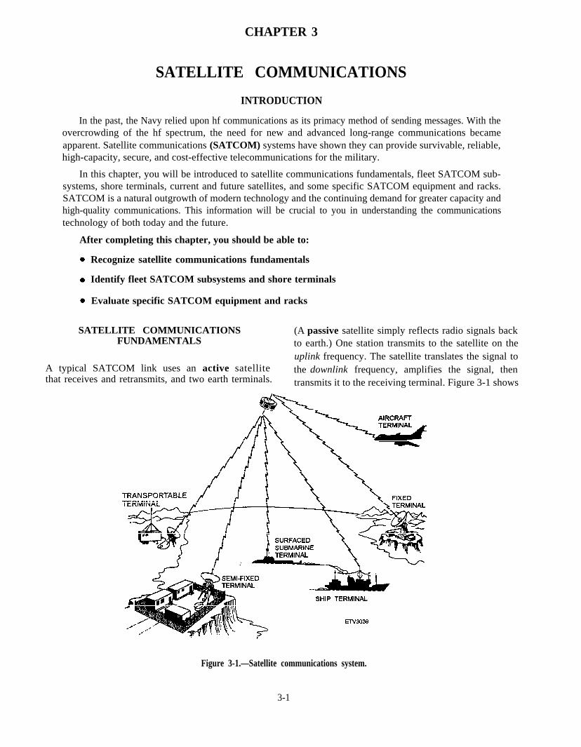
(A passive satellite simply reflects radio signals backto earth.) One station transmits to the satellite on theuplink frequency. The satellite translates the signal tothe downlink frequency, amplifies the signal, thentransmits it to the receiving terminal. Figure 3-1 shows
A typical SATCOM link uses an active satellitethat receives and retransmits, and two earth terminals.
Figure 3-1.—Satellite communications system.
3-1

some of the various earth terminals and how theyinterface. The end use or purpose determines thesystem’s complexity and how the system is used.
ROLE OF SATELLITECOMMUNICATIONS
SATCOM links, one of several kinds of long-distance communications links, interconnect com-munications centers located strategically throughoutthe world. These SATCOM links are part of theDefense Satellite Communications System (DSCS)and Fleet Satellite Communications.
Satellite communications systems are veryimpor tan t to the wor ldwide mi l i t a ry com-munications network for two primary reasons. First,they continue to operate under conditions that causeproblems for other methods of communication.Second, they provide reliable and secure com-munications to previously inaccessible areas. Inmany cases, these communications requirementscan on ly be satisfied by sophisticated satellitecommunications systems. By satisfying such needs,SATCOM makes a significant contribution to theimproved reliability of naval communications.
ADVANTAGES OF SATELLITECOMMUNICATIONS
Some of the unique advantages SATCOM has overconventional long-distance communications are asfollows:
SATCOM links are unaffected by thepropagation problems associated with hf radiocommunications.
SATCOM links are free from the high-attenuation problems of facilities that use wireor cable for routing communications.
SATCOM links span long distances.
The numerous repeater stations required forline-of-sight and troposcatter systems are notneeded.
As you can see, satellite links provide the requiredflexibility and reliability needed to support militaryoperations. In the following paragraphs, we will lookat SATCOM capacity, reliability, vulnerability,flexibility, and limitations.
Capacity
Currently, military SATCOM systems can providecommunications between backpack, shore, airborne,and shipboard terminals. These SATCOM systems canhandle thousands of communications channels at thesame time.
Reliability
SATCOM frequencies are only slightly affectedby atmospheric phenomena and do not depend onreflection or refraction. Reliability is based on the skillof operators and maintenance personnel and thecondition of the satellite communications equipment.
Vulnerability
Communications satellites are relatively safe fromthreats of harm. Because these satellites are in suchhigh orbits, any attempt to disable or destroy themfrom the Earth would be difficult and expensive.However, Earth terminals are a different story. Theyoffer a more attractive target for destruction byconventional methods. But these terminals can beprotected by the same methods taken to protect othervital installations. So overall, the satellite system isnearly free from harm by an enemy.
Operationally, highly directional earth terminalantennas provide a high degree of freedom fromjamming. The wideband system can use antijammingtechniques, which also reduces vulnerability.
Flexibility
Mobile military satellite earth terminals withtrained crews can be deployed and put into operationanywhere in the world within hours.
Limitations
The technical characteristics of the satellite and itsorbital parameters are the main limitations to a satellitecommunications system. Two additional limitingfactors for active satellites are transmitter power andreceiver sensitivity. Energy for electricity is limited towhatever can be produced by the solar cells, whichlimits the satellite’s output power. This problem ismade worse by users who increase their output powerto the satellite, causing the satellite to try to retransmitat the new power level, at the expense of reducingsignals to other users.
3 - 2
FLEET SATELLITECOMMUNICATIONS
T h e F l e e t S a t e l l i t e C o m m u n i c a t i o n s(FLTSATCOM) System provides communications,via satellites, between designated mobile units andshore sites. These links provide worldwide coveragebetween the latitudes of 70 degrees north and 70degrees south. Three satellites are currently in use witha fourth to come online soon: GAPFILLER, LEASAT,FLTSATCOM, and UHF Follow-on (UFO).
System installations are located on ships,submarines, mobile vans, aircraft, and shore stations.Though these installations could operate separately,integrating the system provides message traffic andvoice communications to all DOD long-rangecommunications networks. In addition, certain shorestations provide a back-up capability to other users incase of an outage of any kind, which maintains netconnectivity.
The Navy SATCOM system consists ofinformation exchange subsystems that use thesatellites as (1) relays for communications and control,and (2) quality monitoring subsystems that providedata required to manage satellite resources. Eachsubsystem is structured for specific navalcommunications requirements. The followingsubsystems make up most of the Navy’s FLTSATCOMsystem.
Fleet Satellite Broadcast Subsystem. This is anexpansion of the “Fleet Broadcast,” which hasbeen the central communications medium foroperating naval units.
Common User Digital Information ExchangeSubsystem (CUDIXS) and Navy ModularAutomated Communications Subsystem(NAVMACS). These two installations form acommunications network for transmittinggeneral-service message traffic between shipsand shore installations.
Submarine Satellite Information ExchangeS u b s y s t e m (SSIXS) . T h i s s u b s y s t e mcompliments other communications linksbetween SSBN and SSN submarines and shoreterminals.
Secure Voice Subsystem. This is a narrowbanduhf subsystem that links voice communicationsbetween ships and connects with wide-areashore voice networks.
3-3
Tactical Intelligence Subsystem (TACINTEL).This subsystem is specifically designed forspecial intelligence communications.
Teletypewriter Subsystem. This subsystem is anextension of terrestr ial teletypewritertransmission networks.
Tactical Data Information Exchange Subsystem(TADIXS). This is a one-way broadcast oftactical information from command centersashore to afloat units primarily in support ofover-the-horizon targeting (OTH-T).
Officer in Tactical Command InformationExchange Subsystem (OTCIXS). T h i ssubsystem continues to provide inter-and intra-battle group communications and is now alsodesignated as the return path for ship-to-shoreOTH-T communications.
Demand Assigned Multiple Access (DAMA)Subsystem. This subsystem was designed tomultiplex several subsystems, or users, on onesatellite channel, allowing more satellitecircuits to use a single uhf satellite channel.
Control Subsystem. This subsystem is acommunications network that provides statusreporting and management of system assets
The instal lat ion of subsystem basebandequipment and rf terminals aboard ships is driven bycommunications traffic levels, type of com-munications, and mission requirements. For example,Fleet Broadcast, a common subsystem in naval com-munications, is received by many different types ofships. Atypical suite on a large ship may include FleetBroadcast, CUDIXS, NAVMACS, Secure Voice,TADIXS, OTCIXS, Teletypewriter, and TACINTELequipment.
Most subsystems have very rigid control andaccountability of message and data-link traffic. Allsubsystems have some form of backup mode. Withinthe constraints of equipment capability, eachsubsystem addresses the unique requirements of theuser and the environment in which the user operates.On board your ship, you may not use all these systems,but during your career you will probably come acrossall of them. Now that we have identified the satellitecommunications subsystems, we need to provide you

with a basic understanding of how they operate. Butfirst, we need to discuss FLTSATCOM ShorebasedTerminals.
FLTSATCOM SHOREBASED TERMINALS
SATCOM installations at shore terminals operatefrom existing naval communications centers andcertain command operations centers. Four NavalComputer and Telecommunications Area MasterStations (NCTAMS) have primary responsibility fornaval communications via satellite. They are:
NCTAMS LANT, Norfolk, Virginia
NCTAMS MED, Naples, Italy
NCTAMS WESTPAC, Finegayan, Guam
NCTAMS EASTPAC, Wahiawa, Hawaii
The Naval Computer and TelecommunicationsStation (NCTS), San Diego, California, as part ofTADIXS, provides connectivity between NCTAMSEASTPAC and NCTAMS LANT.
Ten NCTSs are used to retransmit Fleet Broadcastmessage traffic via hf links. In addition, an rf terminalat Yokosuka, Japan, transmits SSIXS and SecureVoice communications to the western Pacific andIndian Oceans. Also, there is landline connectionbetween Japan and NCTAMS WESTPAC to supportTADIXS and OTCIXS transmissions.
Within these facilities, each subsystem consists oftwo parts: the baseband equipment (used to collect andcontrol the transmitted or received communications)and the rf terminal (used by the baseband system totransmit and receive via satellite link). Somesubsystems have the baseband equipment and rfterminals in the same building, while others have thebaseband equipment installed at a remote facilitylocated some distance from the rf terminal. Mostsubsystems use a common rf terminal. However, theFleet Broadcast has an rf terminal specificallydesigned for that subsystem.
FLEET SATELLITE BROADCASTSUBSYSTEM
The Fleet Satellite Broadcast Subsystemprovides the capability to transmit Fleet Broadcastmessage traffic in a high-level jamming en-vironment. The subsystem has 15 subchannels ofencrypted message traffic at an input data rate of 75bps per channel. These subchannels are time-
division multiplexed and are transmitted in a one-way rf transmission at 1200 bps. The shore terminaltransmits this data on a direct-sequence, spread-spectrum shf signal to the satellite, where the signalis translated to uhf and down-linked to thesubscriber. Figure 3-2 shows a block diagram of theFleet Satellite Broadcast Subsystem.
The High-Speed Fleet Broadcast (HSFB) is aplanned upgrade to the Fleet Satellite BroadcastSubsystem. This upgrade will improve broadcasttransmission speed, information through-put (capabil-ity of equipment to process or transmit data during aspecific period of time), and flexibility.
Message Traffic Input
The Fleet Satellite Broadcast message traffic isqueued and/or channel selected by two processor-controlled message switching systems beforetransmission. These systems are the Naval Com-munications Processing and Routing System(NAVCOMPARS) for general service messagetraffic, and STREAMLINER for special intelligencemessage traffic. Fleet weather data from NavalOceanographic Command Centers is also transmittedon nonprocessor controlled channels.
Rf Transmission
The FLTSATCOM satellites have two rf channelsallocated for Fleet Satellite Broadcast message traffic.The primary channel is configured for an shf uplink tothe satellite and for translation within the satellite fortransmission as uhf in the downlink. The second rfchannel is designed for backup use only.
Since two channels are available, and severaldifferent modulation techniques are used for theuplink, there are seven different modes in which the rflink can be transmitted.
In modes 1 through 6, the shf transmissions aremade by the Satellite Communications TerminalAN/FSC-79. Mode 7 operates the rf uplink anddownlink at ultra-high frequencies and uses the uhftransceiver AN/WSC-5(V).
Reception
Subscribers receive the uhf downlink signalthrough the AN/SSR-1 receiver system, whichdemodulates and demultiplexes the signal. Thedemuxed signal is decrypted and read into the
3-4

3-5
3-5
Figu
re 3
-2.—
Flee
t Sa
telli
te B
road
cast
Sub
syst
em.

NAVMACS and TACINTEL processors for messagescreening and printing. (Refer to the discussion ofthese two systems.) Weather data is sent directly toprinters after decryption. Ships not equipped with oneor both of these systems will normally output thebroadcast to teletypewriters.
Fleet Broadcast Retransmission
At selected shore stations, fleet Broadcastmessage traffic is retransmitted on hf links. Thesestations receive the tdm data directly via cable orsatellite.
CUDIXS/NAVMACS
The CUDIXS subsystem is a shorebased in-stallation of processors and peripheral equipment thatprovides K link control of the network and processingat shore installations. Figure 3-3 shows a typicalCUDIXS installation.
NAVMACS is a shipboard message processingsystem that automatically guards a minimum of fourbroadcast channels, serves as an automatedshipboard terminal for CUDIXS, and providesaccountability for all incoming and outgoingmessage processing needs for ships of the fleet.
NAVMACS subscriber terminal equipment is similar toCUDIXS terminal equipment.
The NAVMACS program is designed to addressthe growth requirements in existing installations andthe unique requirements of ships having a high volumeof message traffic. In ships that have a message pro-cessing and distribution system (MPDS), t h eNAVMACS processor interacts with the MPDS pro-cessor. A basic NAVMACS system is shown in fig-ure 3-4.
NAVMACS reads the headings of incomingmessage traffic and separates all messages addressedto the ship or commands for which it is guarding. Thesystem compares every addressee on each incomingfirst run message against entries in its command guardlist (CGL). When the system finds one or morematches between addresses on the first run messageand the entries of the CGL, the message is printed(copied) onto a line printer. If an emergency or Flashprecedence message on a first run is received, it isprinted completely, regardless of whether or not amatch is found. For nonmatches of messages withprecedence lower than Flash, only the heading of themessage is printed.
Together, CUDIXS and NAVMACS provideimproved ship-to-shore and shore-to-ship operational
Figure 3-3.—CUDIXS equipment configuration.
3 - 6

Figure 3-4.—NAVMACS (V) communications interface.
3-7

3-8
Figu
re 3
-5.—
CUDI
XS/N
AVM
ACS
subs
yste
m (
non-
DAM
A).

communications. These improvements help increasemessage traffic through-put rates and traffic volume,and improve link reliability. Figure 3-5 shows bothsides of the CUDIXS/NAVMACS subsystem.
Message Traffic Input
At shore facilities, the primary collection pointfor message traffic to be transmitted or received onthe CUDIXS/NAVMACS r f l ink i s NAV-
SUBMARINE SATELLITEINFORMATION EXCHANGESUBSYSTEM (NON-DAMA)
SSIXS was designed to compliment vlf and mf/hfcommunication links between shorebased submarinebroadcast control authorities (BCAs) and submarines.Figure 3-6 shows a SSIXS subsystem.
This subsystem provides the submarinecommander the ability to receive messages transmittedvia satellite at scheduled intervals ( “ G r o u pBroadcasts”) . Between Group Broadcas t s ,submarines may transmit messages to the BCA,including a request for messages held in queue. Theshore terminal responds with acknowledgements forthe received messages and transmits all messagesaddressed to that particular submarine. Two modes,Group Broadcast and Query/Response, permit thesubmarine to be active or passive, depending on whatthe submarine commander wants. One 25-kHzwideband channel on each of the four FLTSATCOMsatellites has been allotted to SSIXS. A single SSIXSnetwork may have up to 120 submarine subscribers.
COMPARS.
Rf transmission Link Control (Non-DAMA)
The CUDIXS baseband equipment shares acommon rf terminal with other subsystems. At theshore facilities this terminal is a uhf transceiver,AN/WSC-5(V). Aboard ship, NAVMACS uses a uhftransceiver, AN/WSC-3(V). All uhf satellites have 25-kHz-wide channels allocated for CUDIXS/NAVMACS transmissions. Each channel is operatedas a half-duplex uhf link, with a data transmission rateof 2400 bps. The rf modulation is differential encodedphase-shift keying (DPSK).
Figure 3-6.—SSIXS subsystem.
3-9

SECURE VOICE SUBSYSTEMSSIXS has undergone an upgrade (SSIXS II) thatreplaces the SSIXS shore equipment with newcomputer equipment.
Message Traffic Input
At the broadcast control authority (BCA), theconsole keyboard operator, high-speed paper tapereader, or Submarine Message Automated RoutingTerminal (SMART) enters into the SSIXS shoreterminal messages addressed to submarines that havebeen received from AUTODIN, NAVCOMPARS, orlocally over the counter in the message center. Aboardthe submarine, message traffic is input via theteletypewriter or tape reader equipment. SSNsubmarines that have the Data Link Control System(DLCS) installed have an additional input/outputcapability via the sensor interface unit (SIU) for over-the horizon targeting (OTH-T messages.
Rf Transmission Link Control
Ashore, the SSIXS subsystem shares access to thesame satellite rf terminal equipment as the other uhfSATCOM subsystems, with the exception ofCOMSUBGRU SEVEN, Yokosuka, Japan, which isequipped with dedicated AN/WSC-3 transceivers.
Since each BCA is located some distance awayfrom the Naval Computer and TelecommunicationsArea Master Station (NCTAMS), line modems andland lines are required for interconnection. Thesubmarine uhf rf terminal is the single-channel, half-duplex AN/WSC-3. SSIXS transmissions are at 4800bps. The capability to operate SSIXS in the DAMA net(see the section on DAMA) has been successfullydemonstrated and will be used in the future. Eachsubscriber to a SSIXS network is assigned a uniqueidentification number that is used in all transmissionsto or from the subscriber. The identification numbersare stored within the shore station and subscriberprocessors and are used for the following purposes:
At the shore stations, the subscriber iden-tification number, when combined with broadcasts,determines the number of times message traffic istransmitted to the subscriber.
When a subscriber makes a transmission to theshore station, the identification number is included. Theshore station will not acknowledge a transmissionwithout receiving the identification number.
The subscriber uses the number to screenincoming message traffic. Any data that is notaddressed to that particular subscriber is discarded.
3-10
The Secure Voice subsystem enables thetransmission of ship-to-ship, ship-to-shore, and shore-to-ship voice communications via satellite relay.Figure 3-7 shows a Secure Voice subsystem.(AUTOSEVOCOM has been replaced by radiowireline interface (RWI) at all NCTAMS shoreactivities.) The subsystem transmits and/or receivessecure voice communications via a half-duplex, push-to-talk satellite link. Channels on each of the fourFLTSATCOM satellites have been allocated for use bythe Secure Voice subsystem. Control of the voicechannels is maintained by the Secure Voice controllerat the responsible NCTAMS/ NCTS.
The subsystem uses digitized voice at a data ratelow enough to be compatible with a 3-kHz voicechannel and is considered narrowband. The sound ofNarrowband Secure Voice is very distinctive. Onceyou hear it, you won’t forget it. The system uses specialanalog-to-digital processing of the speech signal at thehandset terminal and the rf transmission rate is 2400bps.
The Secure Voice subsystem has dedicated rfchannels on the uhf SATCOM satellites as well asdedicated DAMA time slots where DAMA nets havebeen established.
Voice Transmission
The rf terminal installations on mobile platformsdetermine the manner in which a Secure Voicetransmission is made. These mobile platforms maybecategorized into two types:
The small ship/submarine that share a single-channel AN/WSC-3(V) uhf transceiver andcryptographic equipment between NAVMACS orSSIXS and a Secure Voice terminal.
Larger ships that have two or more AN/ WSC-3(V) uhf transceivers and cryptographic equipment areinstalled. This installation normally has a transceiverdedicated to Secure Voice.
Secure Voice use is accomplished by either of twomethods. In the first method, ships access a SecureVoice channel if the channel is not in use. The shipcontacts another ship directly by using the availablechannel. When coordination of voice communicationswith shore commands is required, the ship contacts thevoice controller who, in turn, tells the recipient(s) of anincoming voice transmission.

Figure 3-7.—Secure Voice subsystem.
The second method requires a different processand is used if the channels are busy or if proceduresrequire this method. For the small ship or submarine, avoice transmission request must be sent by message tothe Secure Voice controller. A small ship uses theCUDIXS/NAVMACS network for the message. Thesubmarine may transmit a voice-channel requestduring a random-access time period in the SSIXS. Inboth cases, the request is passed from the receptionpoint ashore to the voice controller. The voice
controller coordinates the voice transmission byassigning a voice channel, contacting the unit that willreceive the voice transmission, and following throughwith the transmission.
Radio Wireline Interface
The Radio Wireline Interface (RWI) w a sdeveloped to access and interconnect existing andfuture Secure Voice subsystems and equipment. It pro-vides the capability to connect shorebased worldwide
3-11

3-12
Figu
re 3
-8.—
DAM
A-co
nfig
ured
TAC
INTE
L su
bsys
tem
.

terrestrial (wireline) systems with the SATCOM,Defense Satellite Communications Systems, andalternate hf systems. This system extends shorecommunications seaward and gives commands at seathe same Secure Voice telephone communicationscurrently provided to the worldwide shore es-tablishment. The RWI provides interconnectionamong the Secure Voice Improvement Program(SVIP) channels (STU-III units), a RED telephonebus, the Advanced Narrowband Digital VoiceTerminal, SATCOM radio terminals (uhf, shf, and inthe future, ehf), and hf radio links.
TACTICAL INTELLIGENCE SUBSYSTEM
The Tactical Intelligence subsystem (TACINTEL)is used to transmit special-intelligence communica-tions. A link-control protocol has been adapted to a for-mat required for communication across a DAMA-supported channel using a polling scheme that can sup-port a net membership of 23 subscribers. A portion of aDAMA 25-kHz channel on each of the FLTSATCOMsatellites has been allocated for TACINTEL. A TACIN-TEL subsystem is shown in figure 3-8.
TACINTEL also processes time-sensitive sensordata and other data essential to Indications andWarnings and OTH-Targeting. In addition, thissystem, unlike CUDIXS/NAVMACS, can be used fordirect ship-to-ship interchange of this data.
Rf Transmission
TACINTEL baseband equipment uses an rfterminal in common with other subsystems at bothshore facilities and subscriber terminals. Shorefacilities use an AN/WSC-5(V); subscribers use an
AN/WSC-3(V). The TACINTEL channel operates as ahalf-duplex uhf link at 1200, 2400, or 4800 bps.Modulation is DPSK
Subscriber Reception
Each subscriber has an identification numberrecognized by the subscriber processor. This numberserves as the initial basis for incoming messagescreening. Screened message traffic is sent to theTACINTEL peripheral equipment (printer) or theinterfacing systems. The remaining message traffic isdiscarded without release.
Future TACINTEL
The TACINTEL II program will upgrade theexisting TACINTEL and incorporate state-of-the-arthardware and software. It will be a computer-basedmessage communications system, enabling automaticreceipt and transmission of Special Intelligencecommunications for both ashore and afloat users.During the transition, it will be compatible with thepresent TACINTEL.
TELETYPEWRITERSUBSYSTEM
The Teletypewriter Subsystem expands existingteletypewriter communications networks by usingsatellites as relay stations.
The Navy continues to have numerous uses for the75-bps tty. These include dedicated full-timeterminations for beyond-line-of-sight tactical andreport-back circuits and as backup connectivity forne tworks such as CUDIXS/NAVMACS andTACINTEL. A non-DAMA-configured teletypewritersubsystem is shown in figure 3-9.
Figure 3-9.—Teletypewriter subsystem-non DAMA.
3-13

TADIXS/OTCIXS
TADIXS supports the exchange of Over-the-Horizon Targeting (OTH-T) information betweenshore and fleet-based computer systems that supportNavy cruise missile operations. Surface ships andsubmarines operate in a TADIXS receive-only mode.OTH-T data from the fleet destined for shore orother fleet users is sent by the afloat Tactical DataProcessors (TDPs) through the TADIXS ON-143(V)6/USQ to the OTCIXS ON-143 (V)6/USQ
for transmission over the OTCIXS satellite. ATADIXS surface ship installation is shown in figure3-10. Each OTCIXS-equipped surface ship orsubmarine can enter both out-going teletype andTDP traffic simultaneously.
Rf Transmission Link Control
The TADIXS satellite link network operates in ahalf-duplex manner at a data rate of 2400 bps in apermanently assigned time slot of a uhf DAMAchannel. Control of message traffic transmission is
Figure 3-10.—TADIXS surface ship installation.
3-14

achieved by a polling and controlled access protocolinstalled in the TADIXS radio controller (shore)software and the TADIXS satellite link controller(afloat) software.
In the non-DAMA mode, OTCIXS operates in ahalf-duplex manner at a data rate of 2400 bps using adedicated uhf channel. When functioning in theDAMA mode, OTCIXS operates at a data rate of 1200or 2400 bps in a permanently assigned time slot of a uhfDAMA channel. Control of message traffictransmission is achieved by a demand-assigned accessprotocol installed in the OTCIXS radio controller(shore) and satellite link controller (afloat) software.
Message Traffic Reception
Each subscriber in the TADIXS network has aunique identification number recognized by thesubscriber processor. This number serves as the initialbasis for incoming message traffic screening.TADIXS or OTCIXS satellite link controllers (onafloat units) compare redundant receptions foraccuracy and form the most accurate composite of thetraffic received.
For surface ship and submarine users, screenedmessage traffic is sent to the teletypewriter or TDPsystem, as applicable. The rest of the traffic isdiscarded. The reception of traffic does not make thesatellite link controller send an acknowledgement.This allows afloat platforms to receive traffic whileoperating in an emission control (EMCON) en-vironment.
DEMAND-ASSIGNED MULTIPLE ACCESS(DAMA) SUBSYSTEM
The uhf DAMA subsystem was developed tomultiplex several baseband systems or users on one25-kHz satellite channel. This had the effect of addingmore satellite circuits per channel to the uhf SatelliteCommunications System. Without uhf DAMA, eachsatellite communications subsystem requires aseparate satellite channel.
DAMA equipment accepts encrypted data streamsfrom independent baseband sources and combinesthem into one continuous serial output data stream.DAMA interfaces the Navy uhf SATCOM subsystemsand the AN/WSC-5(V) and DAMA-compatibleAN/WSC-3(V) transceivers. The DAMA unit (TD-1271B/U multiplexer) includes a modem, eliminatingthe need to use a separate modem at the AN/WSC-5(V)or the modem within the AN/WSC-3(V). Thebaseband equipment input or output (I/O) data rate
with DAMA equipment can be 75, 300, 600, 1200,2400, 4800, or 16,000 bps. The DAMA transmissionrate on the satellite link (burst rate) can be 2400,9600,19,200, or 32,000 symbols per second (sps).CUDIXS/NAVMACS, Secure Voice, and OTCIXScurrently use 2400 bps. TACINTEL operates at 2400or 4800 bps, depending upon the ocean area.
The DAMA multiplexed data stream is divided intoframes, with each frame being 1,386 seconds long. Eachframe is subdivided into time slots as shown in figure3-11. Most of the DAMA frame formats are derivedfrom this basic format. In the following paragraphs, wewill name and describe the purpose of each slot.
Channel Control Order Wire (CCOW) Slot
This slot is used to transmit system timing andcontrol information from the channel controller tosubscriber units only. It provides subscriber units withsystem timing, configuration, and satellite rf controlinformation. It occurs at the beginning of each frame.
Return Channel Control Order Wire(RCCOW) Slot
This time slot provides limited order wirecapability for DAMA-related subscriber-to-channelcontroller communications. It is used for transmissionfrom the subscriber to the channel controller.
Ranging Time Slot
This is the time slot during which the user’sTD-1271B/U determines the range between the userterminal and the satellite to set the transmitter syn-chronization required for timing. All DAMA multi-plexer transmit times are referenced to the satellite.
Link Test Slot
The link test slot is used to evaluate theperformance of the satellite link. Each subscriber isable to transmit a fixed data stream through thesatellite, receive that bit stream, and then perform erroranalysis automatically.
Figure 3-11.—Basic DAMA frame format.
3-15

Data Time Slots
These are the time slots during which userstransmit or receive data. There are three segments oftime slots in each frame, designated A, B, and C.Segment A may contain from one to five circuits; Bmay contain from one to eleven circuits; and C maycontain from one to six circuits. The number of circuitsin each group depends on the baseband data rate, theforward correction rate, and the transmission burstrate, as influenced by the radio frequency interference(RFI) environment.
Current Operation
For communications on the eastern Pacificsatellite, a master control station is installed atNCTAMS EASTPAC. This same pattern of DAMAequipment installations has been followed atNCTAMS LANT, MED, WESTPAC, and NTCS.Each master control station has multiple multiplexerinstalled, and each TD-1271B/U multiplexer canaccommodate up to four circuits. The number ofmultiplexer installed aboard each ship variesaccording to platform requirements.
Any DAMA-equipped platform with full-duplexcapability can be designated a channel controller. Thiscapability provides an emergency backup for theshorebased master controller terminals. A DAMAsubscriber who is designated a channel controller willprovide all the required CCOW functions for DAMAsystem control of a particular rf channel.
Operationally, the user terminal will have itsbaseband port automatically connected to a data timeslot when the proper slot number is keyed into themultiplexer front panel keyboard. Each SATCOMsubsystem that uses DAMA will have a specific slotnumber. Circuits will normally be operated on a nettedbasis, and circuit numbers will be assigned byCOMNAVTELCOM and/or FLTCINC.
Transition
Transition to DAMA is taking place in a mannerthat allows subscribers converted to DAMA tocommunicate with those who have not been converted.During the transition period, equipment installedat shorebased master stations will form gatewaysbetween DAMA and non-DAMA circuits. In thefollowing paragraphs, we will discuss subsystems thatare either currently undergoing conversion to DAMA
3-16
or are planned for conversion, so you will know what toexpect in the future.
Secure Voice —DAMA is now being phased intothe Secure Voice Subsystem. A DAMA-configuredSecure Voice Subsystem is shown in figure 3-12.
CUDIXS/NAVMACS —NAVMACS platformswill be gradually transitioned to DAMA. Thistransition will start when CUDIXS shore andCUDIXS/NAVMACS ship hardware and softwarehave been modified for compatibility with DAMA. Atthat time, a transition will begin allowing DAMA ornon-DAMA ships to communicate with the CUDIXSshore terminal. A DAMA-configured CUDIXS/NAVMACS subsystem is shown in figure 3-13.
Teletypewriter —Teletypewriter capability viaDAMA becomes available as DAMA is installed oneach platform. To provide maximum flexibility duringthe transition, capability is provided at the shorebasedmaster control stations to interface non-DAMA andDAMA users. Figure 3-14 shows a DAMA-configuredteletypewriter subsystem.
CONTROL SUBSYSTEM
The Control Subsystem is structured to performthe following tasks:
Sense and collect system status information in adefined geographical area and on a worldwidescale.
Control system resources and the degradationof system capability.
The Control Subsystem is a combination of severalareas and levels of command. The major players arelisted below:
The Chief of Naval Operations is the executiveauthority for all SATCOM system.
The Commander, Naval Space Command isresponsible for the operational control and managementof these systems and for the effective operation andmaintenance of assigned Navy resources for theDepartment of Defense.
The Naval Computer and TelecommunicationsCommand performs the required functions to pro-vide day-to-day control and operation of naval satellitecommunications assets. With coordination, systemresources can be adjusted to meet operational needs.

Figure 3-12.—DAMA-configured Secure Voice Subsystem.
Supporting the control subsystem are NCTAMS,NCTS, the USAF Satellite Operations Center, andcontractor-operated control facilities.
The key to controllability lies in having manypoints for sensing the status of subsystems andequipment operation. Status data may be collected byoperators or by special facilities or equipment. Thereare many points within each subsystem wheresubsystem and equipment operational status is
collected. Also, several subsystems/systems have theability to provide a printout of status information.
Transmission of status data from the NCTAMS,NCTS, and USAF Satellite Operations Center is viateletypewriter order wire. The Naval Computer andTelecommunications Command maintains asubstantial quantity of updated status data in computerfiles. A diagram of the Control Subsystem is shown infigure 3-15.
3-17

3-18
Figu
re 3
-13.
—DA
MA-
conf
igur
ed C
UDIX
S/NA
VMAC
S su
bsys
tem
.

Figure 3-14.—DAMA-configured teletypewriter subsystem.
Figure 3-15.—Contro1 Subsystem functional diagram.
3-19

3-20
Figu
re 3
-16.
—Uh
f sa
telli
te c
over
age
area
s.

SATELLITES
In 1976, three satellites were placed into orbit overthe Atlantic, Pacific, and Indian Oceans. Thesesatellites, called MARISATs, were procured by andare managed by the COMSAT General Corporation.Each satellite has three uhf channels for military use(one wideband 500-kHz channel and two narrowband25-kHz channels). The uhf section of each satellite isleased to the Navy for communications. To distinguishthe special management and control functions forcommunications on these uhf channels, the Navy hasgiven the leased MARISAT satellite assets the nameGAPFILLER.
Current planning calls for no Navy use ofGAPFILLER satellites after the mid-1990’s. Satellitecoverage will then be provided by a combination ofF L T S A T and L E A S A T until the new U H FFOLLOW-ON (UFO) satellites are placed intoservice. The Navy plans to have two operationalsatellites in each of four satellite coverage areas. Eachsatellite coverage area can be terminated in at least twoNCTAMS, allowing around-the-world connectivity.You can see this connectivity in figure 3-16.
FLTSATCOM SATELLITE
The FLTSATCOM satellite consists of two majorparts: a payload module that includes the antennas anda space craft module with a solar array. The payloadmodule contains the uhf, shf, and S-band (tracking,telemetry, and command) communications equipmentantennas. The communications equipment is mountedinternally on side panels that cover this section of thesatellite.
The space craft module contains nearly all othersubsystem equipment, including sensors, attitude andvelocity control, telemetry, tracking and command,and electrical power distribution. The spacecraft isstabilized on three axes, and the body-fixed antennasare kept pointing at the sun by a clock drive. AFLTSATCOM satellite is shown in figure 3-17.
E a c h F L T S A T C O M s a t e l l i t e c a n r e l a ycommunications on 23 separate uhf channels. Of the23 channels, 10 are 25-kHz channels, 12 are 5-kHzchannels, and one is a 500-kHz channel. The ten 25-kHz channels are dedicated for Navy use. Each 25-kHzuhf down-link channel has a separate transmitter.Channel one, used in primary mode for Fleet Broadcasttransmissions, incorporates signal processing withinthe satellite (the shf up-link signal is translated to uhf
Figure 3-17.—FLTSATCOM satellite.
for down-link transmission). In addition, two of theFLTSATCOM satellites have ehf packages attached.
FLTSAT Extremely-High-Frequency Package(FEP)
The Fleet Satellite (FLTSAT) Extremely-High-Frequency (EHF) Package (FEP) provides ehfcommunications capability for Army, Navy, and AirForce ground, airborne, and ocean-going terminals.Two FEPs are currently in orbit, carried aboard twomodified uhf FLTSATs, numbers seven and eight.
FEP operates at ehf frequencies of approximately20-GHz on the down-link and 44-GHz on the up-link.It has two antenna beams: (1) a dual-frequency spotbeam steerable by ground command, and (2) an earthcoverage beam that uses separate horn antennas fortransmit and receive.
LEASAT SATELLITE
The LEASAT satellite has seven 25-kHz uhfdown-link channels, one 500-kHz wide-band channel,and five 5-kHz channels. One of the seven 25-kHzdown-link channels is used for Fleet Broadcast.The broadcast up-link is shf, with translation touhf taking place in the satellite. The remaining
3-21

six channels function as direct relay channels withseparate repeaters. A LEASAT satellite is shown infigure 3-18.
Compared to FLSATCOM satellites, LEASATsatellites have a reduced number of 25-kHz channels.However, they can still serve expanding NavySATCOM requirements by using the groundbasedDAMA technique, effectively using each satellitechannel more efficiently.
UHF FOLLOW-ON SATELLITE
The purpose of the Ultra-High-Frequency Follow-On Satellite System (UHF F/O) is to provide satellitecommunications for DOD and other governmentagencies through satellites in geosynchronous orbit.The current satellites, GAPFILLER, FLTSATCOM,and LEASAT are approaching the end of their normalmission life. UHF F/O will provide the neededreplenishment satellites. The strategy for replacementis to use existing FLTSATCOM and LEASAT assetsfully, while deploying the UHF F/O satellites tominimize communications disruptions as theFLTSATCOM and LEASAT satellites fail or reach theend of their useful life. An exploded view of a UHFF/O satellite is shown in figure 3-19.
Communications Capability
The uhf communications subsystem consists ofreceive and transmit antennas, a low-noise pre-amplifier, 25- and 5-kHz channel receivers and
Figure 3-18.—LEASAT satellite.
transmitters, and an output multiplexer. The shfcommunications subsystem provides shf anti-jam up-link capability for Fleet Broadcast (which is down-linked as uhf) and consists of receive and transmitantennas, the receiver, a dual channel processor, andthe beacon transmitter. Signals received by the shfreceive antenna are fed to the shf receiver. In turn, theprocessor provides Fleet Broadcast outputs that are fedto uhf communications subsystem for down-link. Themultiplexed anti-jam broadcast capability of the UHFF/O permits up to three broadcast channels to be up-linked and down-linked simultaneously.
On the fourth and subsequent satellites deployed,an ehf communications subsystem will provide threeehf broadcast channel up-links and seven ehfcommunications channel up-links. Each of these ehfup-links will be capable of being down-linked as ehfonly, uhf only, or simultaneously as uhf and ehf. UHFF/O will also have the capability of transmitting andreceiving ehf telemetry and command data.
User interfaces for UHF F/O are identical to thoseof the current FLTSATCOM and LEASAT constella-tion. The uhf portion of the UHF F/O system iscompatible with all existing Navy uhf terminals exceptthose using frequency-hopping techniques.
Channel Allocations
The UHF F/O satellite channels are allocated andgrouped as follows:
Group I has a single 25-kHz bandwidth channelwith a variable satellite translation frequency and a jamresistant shf up-link.
Group II has nine 25-kHz bandwidth channelswith a satellite translation frequency of 41 MHz.
Group III has eight 25-kHz bandwidth channelswith a satellite translation frequency of 33.6 MHz.
Group IV has eight 5-kHz bandwidth channelswith a satellite translation frequency of 73.1 MHz.
Group V has thirteen 5-kHz bandwidth channelswith a satellite translation frequency of 53.6 MHz.
MILSTAR
MILSTAR is a new generation Satell i teCommunications (SATCOM) system being developedby the Navy, Army, and Air Force for two primarypurposes. First, it will provide a survivable
3-22

Figure 3-19.—UHF Follow-On satellite exploded view.
communications capability to the National CommandAuthority (NCA). Second, it will provide sufficientcommunications support for both strategic and tacticalmissions. The primary objective of the MILSTARprogram is to develop and deploy an affordable, jam-resistant SATCOM system that will meet both long-haul and local communications needs.
MILSTAR will use communications terminalsthat will provide Secure Voice (SV), Teletype (TTY),data, and facsimile EHF SATCOM. MILSTARterminals will be installed on aircraft, in fixedtelecommunications centers, landbased tacticalelements, shorebased telecommunications centers,surface ships, and submarines.
In the following paragraphs, we will look at someof the equipment associated with satellite com-munications.
SATELLITE EQUIPMENT
The equipment used in Navy SATCOM sub-systems can be divided into two general groups, rfterminals and the baseband equipment common to aprocessor installation. The selection of specificequipment is determined by the operating en-
vironment—whether installation is to be aboard a ship,submarine, aircraft, or shore installation. In thischapter, we will limit our discussion primarily tocommonly used shipboard and shore equipment.
Satellite Communications TerminalAN/FSC-79
The AN/FSC-79 terminal processes and converts70-MHz signals to X-band (shf) transmitted signals. Italso converts received signals from X-band to 70 MHz.This terminal can simultaneously transmit a spreadspectrum carrier and receive a satellite beacon signal.The design of the terminal provides redundancy inmany components to ensure a high degree ofavailability. The terminals are installed at NCTAMSLANT, MED, WESTPAC, EASTPAC, and NCTS,Stockton (contractor operated).
Uhf Transceiver AN/WSC-5(V)
The AN/WSC-5(V) transceiver provides aneight-circuit, full-duplex data operation or, as analternative, six full-duplex data circuits and twoFM audio or tone-group circuits. It also providesan interface for connectivity to the uhf DAMA
3-23

Figure 3-20.—Uhf transceiver AN/WSC-5(V).
equipment. Figure 3-20 shows an AN/WSC-5(V)transceiver installation.
This transceiver is capable of three types ofmodulation/demodulation:
• Frequency modulation/demodulation with pre-emphasis/ de-emphasis for voice transmission/ reception.
• Frequency modulation/demodulation without pre-emphasis/de-emphasis for tone-group transmission/reception.
• Differentially encoded phase-shift keying using theOM-43A/USC modem. The transceiver has a 70-MHzinterface for connection to either the modem or the TD-1271B/U DAMA multiplexer.
All four NCTAMS have AN/WSC-5(V)transceivers installed.
The C-11330/WSC-5(V) shown in figure 3-21provides for remote control of the AN/WSC-5(V) forteletype operation. The C-11330/WSC-5(V) is similar tothe C-9899/WSC-3, except that it uses +6 Vdc for the
keyline signal and indicator lamps. Both units haveidentical front panels.
Transceiver AN/WSC-3(V)
To be consistent in this discussion, we will refer toboth the AN/WSC-3 and AN/WSC-3(V) transceivers
Figure 3-21.—Control-Indicator C-11330/WSC-5(V)or C-9899/WSC- 3.
3-24

Figure 3-22.—Uhf radio RT-1107/WSC-3.
as AN/WSC-3. A single AN/WSC-3 (RT-1107/WSC-3)is shown in figure 3-22.
The AN/WSC-3 transceiver is used primarilyaboard ship, at Marine Corps terminals, and at selectedshore installations. It has various configurationsdesigned to meet the particular requirements of theseplatforms. The configuration differences are identified inthe AN/WSC-3 variations table, table 3-1.
The transceiver can be operated in either satellite orline-of-sight mode, either locally or remotely. Amodulation control permits selection of PSK data ratesfrom 75 to 9600 bps, FSK modulation at 75 bps, and FMor AM modulation for voice. The rf output is 30 wattsAM and 100 watts for FM, PSK, and FSK
The AN/WSC-3A, AN/WSC-3A(V)2 and (V)3have been modified for use with the DAMA subsystem.The AN/WSC-3(V)15, (V)17, and (V)19 aremanufactured as DAMA-capable.
The transceiver has two control indicators forremote operations. The C-9351/WSC-3, shown in figure3-23, provides for remote control of the AN/WSC-3 asdescribed in the table 3-1 description. As we mentionedbefore, the C-9899/WSC-3 provides for remote teletypeoperation. Two built-in modems are included with thetransceiver.
Receiver Systems AN/SSR-1 and 1A
You have probably seen this receiver since it is installedaboard most naval surface vessels. It enables ships to receiveFleet Satellite Broadcast. The received carrier may containeither FM or PSK modulation; the preferred demodulation isselected manually with a switch associated with thereceiving set. The AN/SSR-1 can drive high-level teletypeequipment. The AN/SSR-1A can drive both high- and
Figure 3-23.—Control-Indicator C-9351/WSC-3.
3-25

Table 3-1.—AN/WSC—3 Variations
3-26

Table 3-1.—AN/WSC—3 Variations—Continued
3-27


![Electronics Technician - pudn.comread.pudn.com/downloads23/ebook/75545/[eBook] - - US Navy... · Electronics Technician ... such basic information, these volumes refer you to the](https://img.pdfslide.us/doc/110x75/5aee08ce7f8b9a3b2e917042/electronics-technician-pudn-ebook-us-navyelectronics-technician-such.jpg)