Embed Size (px)
Citation preview

Technical�training.Product�information.
BMW�Service
G01�Powertrain

General�information
Symbols�used
The�following�symbol�is�used�in�this�document�to�facilitate�better�comprehension�or�to�draw�attentionto�very�important�information:
Contains�important�safety�information�and�information�that�needs�to�be�observed�strictly�in�order�toguarantee�the�smooth�operation�of�the�system.
Information�status�and�national-market�versions
BMW�Group�vehicles�meet�the�requirements�of�the�highest�safety�and�quality�standards.�Changesin�requirements�for�environmental�protection,�customer�benefits�and�design�render�necessarycontinuous�development�of�systems�and�components.�Consequently,�there�may�be�discrepanciesbetween�the�contents�of�this�document�and�the�vehicles�available�in�the�training�course.
This�document�basically�relates�to�the�European�version�of�left�hand�drive�vehicles.�Some�operatingelements�or�components�are�arranged�differently�in�right-hand�drive�vehicles�than�shown�in�thegraphics�in�this�document.�Further�differences�may�arise�as�the�result�of�the�equipment�specification�inspecific�markets�or�countries.
Additional�sources�of�information
Further�information�on�the�individual�topics�can�be�found�in�the�following:
• Owner's�Handbook• Integrated�Service�Technical�Application.
Contact:�[email protected]
©2017�BMW�AG,�Munich
Reprints�of�this�publication�or�its�parts�require�the�written�approval�of�BMW�AG,�Munich.
The�information�contained�in�this�document�forms�an�integral�part�of�the�BMW�Group�TechnicalQualification�and�is�intended�for�the�trainer�and�participants�in�the�seminar.�Refer�to�the�latest�relevantinformation�systems�of�the�BMW�Group�for�any�changes/additions�to�the�technical�data.
Information�status:�June�2017Technical�training.

G01�PowertrainContents1. Introduction.............................................................................................................................................................................................................................................1
1.1. Models.....................................................................................................................................................................................................................................11.1.1. Overview.............................................................................................................................................................................................21.1.2. BMW�M�Performance�Automobiles........................................................................................................2
1.2. Overview�of�system�descriptions.................................................................................................................................................21.3. Drive�comparison�of�G30�with�G01..........................................................................................................................................31.4. Engine�designation.............................................................................................................................................................................................4
2. Engines............................................................................................................................................................................................................................................................52.1. Overview...............................................................................................................................................................................................................................52.2. B46�Engine......................................................................................................................................................................................................................5
2.2.1. Technical�data............................................................................................................................................................................62.2.2. Special�features......................................................................................................................................................................7
2.3. B58�engine.......................................................................................................................................................................................................................82.3.1. Technical�data............................................................................................................................................................................82.3.2. Special�features..................................................................................................................................................................10
2.4. System�wiring�diagram.............................................................................................................................................................................112.5. Intake�air�system.................................................................................................................................................................................................13
2.5.1. Air� intake�duct.......................................................................................................................................................................132.5.2. Charge�air�cooling...........................................................................................................................................................14
3. Cooling.........................................................................................................................................................................................................................................................163.1. Active�air�flap�control...................................................................................................................................................................................16
3.1.1. System�wiring�diagram............................................................................................................................................16
4. Fuel�Supply.........................................................................................................................................................................................................................................174.1. Gasoline�engine...................................................................................................................................................................................................17
5. Engine�Electrical�System..........................................................................................................................................................................................195.1. Engine�control�unit..........................................................................................................................................................................................195.2. Integrated�supply�module....................................................................................................................................................................195.3. MSA�Connected�1.0.....................................................................................................................................................................................20
5.3.1. Advantages................................................................................................................................................................................215.3.2. MSA�Connected�1.0�situations.................................................................................................................225.3.3. Sensors............................................................................................................................................................................................235.3.4. Dependent�optional�equipment................................................................................................................245.3.5. Notes�for�Service.............................................................................................................................................................24
6. Automatic�Transmission.............................................................................................................................................................................................256.1. Transmission�variant.....................................................................................................................................................................................256.2. Special�features....................................................................................................................................................................................................26
G01�PowertrainContents
6.3. Designation.................................................................................................................................................................................................................266.4. Sport�automatic�transmission.......................................................................................................................................................276.5. ConnectedShift.....................................................................................................................................................................................................276.6. Configuration�options.................................................................................................................................................................................28
6.6.1. Influence�of�the�driving�experience�switch..............................................................................286.7. Transmission�emergency�release............................................................................................................................................286.8. Towing.................................................................................................................................................................................................................................296.9. System�wiring�diagram.............................................................................................................................................................................30
7. Four-Wheel�Drive......................................................................................................................................................................................................................327.1. System�wiring�diagram.............................................................................................................................................................................33

G01�Powertrain1.�Introduction
1
The�development�code�for�the�new�3rd�generation�BMW�X3�is�G01.�For�the�market�introduction�inNovember�2017,�all�models�will�be�equipped�as�standard�with�an�8-speed�automatic�transmission�andthe�xDrive�all-wheel�drive.�A�manual�gearbox�will�not�be�offered.
G01�Drive
1.1.�ModelsThe�newly�developed�B�engine�generation�(modular�strategy)�will�be�used�in�all�G01�models.All�engines�comply�with�the�ULEV�or�SULEV�exhaust�emission�standards.
• ULEV�=�Ultra-Low�Emission�Vehicle• SULEV�=�Super�Ultra-Low�Emission�Vehicle
G01�Powertrain1.�Introduction
2
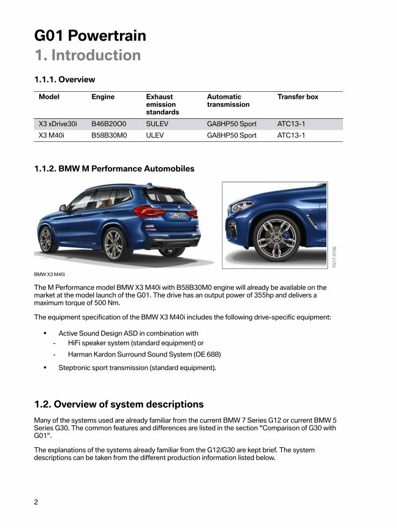
1.1.1.�Overview
Model Engine Exhaustemissionstandards
Automatictransmission
Transfer�box
X3�xDrive30i B46B20O0 SULEV GA8HP50�Sport ATC13-1X3�M40i B58B30M0 ULEV GA8HP50�Sport ATC13-1
1.1.2.�BMW�M�Performance�Automobiles
BMW�X3�M40i
The�M�Performance�model�BMW�X3�M40i�with�B58B30M0�engine�will�already�be�available�on�themarket�at�the�model�launch�of�the�G01.�The�drive�has�an�output�power�of�355hp�and�delivers�amaximum�torque�of�500 Nm.
The�equipment�specification�of�the�BMW�X3�M40i�includes�the�following�drive-specific�equipment:
• Active�Sound�Design�ASD�in�combination�with- HiFi�speaker�system�(standard�equipment)�or- Harman�Kardon�Surround�Sound�System�(OE�688)
• Steptronic�sport�transmission�(standard�equipment).
1.2.�Overview�of�system�descriptionsMany�of�the�systems�used�are�already�familiar�from�the�current�BMW�7�Series�G12�or�current�BMW�5Series�G30.�The�common�features�and�differences�are�listed�in�the�section�"Comparison�of�G30�withG01”.
The�explanations�of�the�systems�already�familiar�from�the�G12/G30�are�kept�brief.�The�systemdescriptions�can�be�taken�from�the�different�production�information�listed�below.
G01�Powertrain1.�Introduction
3
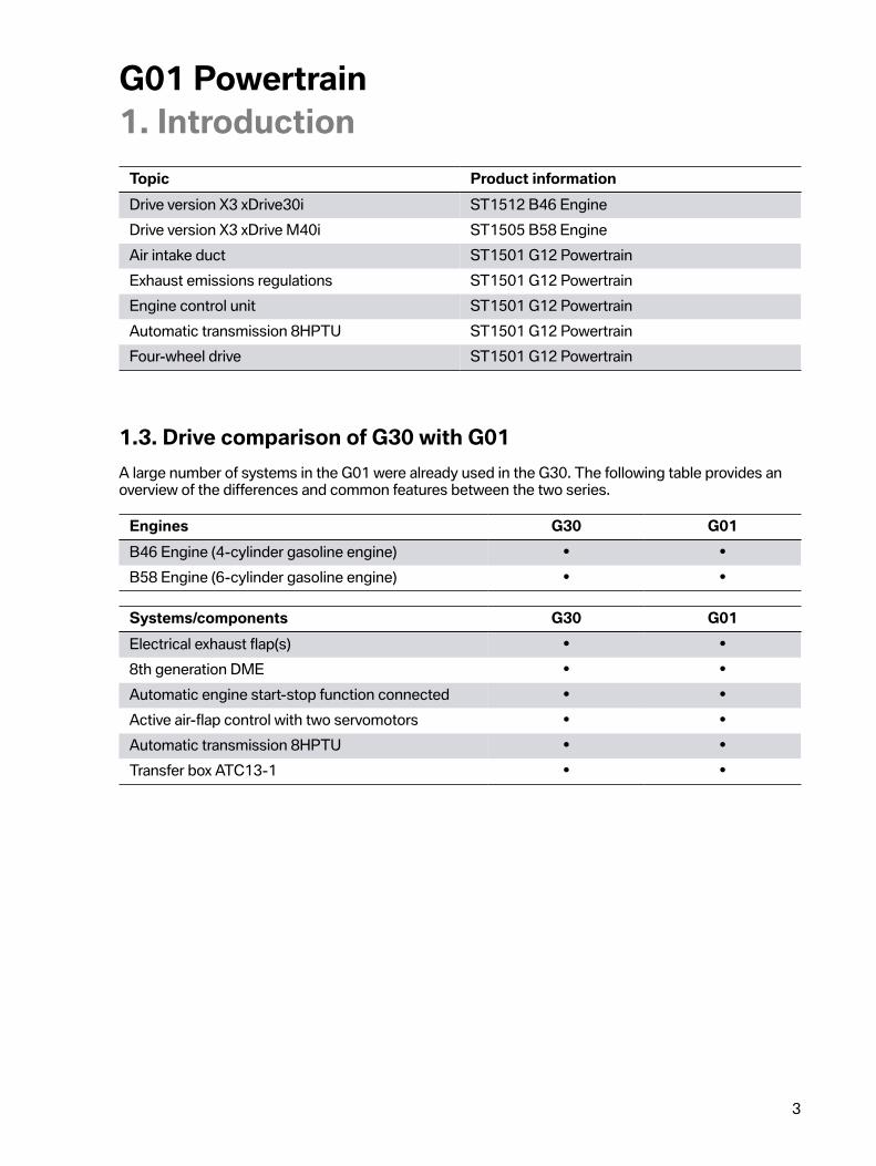
Topic Product�informationDrive�version�X3 xDrive30i ST1512�B46�EngineDrive�version�X3�xDrive�M40i ST1505�B58�EngineAir�intake�duct ST1501�G12�PowertrainExhaust�emissions�regulations ST1501�G12�PowertrainEngine�control�unit ST1501�G12�PowertrainAutomatic�transmission�8HPTU ST1501�G12�PowertrainFour-wheel�drive ST1501�G12�Powertrain
1.3.�Drive�comparison�of�G30�with�G01A�large�number�of�systems�in�the�G01�were�already�used�in�the�G30.�The�following�table�provides�anoverview�of�the�differences�and�common�features�between�the�two�series.
Engines G30 G01B46�Engine�(4-cylinder�gasoline�engine) • •B58�Engine�(6-cylinder�gasoline�engine) • •
Systems/components G30 G01Electrical�exhaust�flap(s) • •8th�generation�DME • •Automatic�engine�start-stop�function�connected • •Active�air-flap�control�with�two�servomotors • •Automatic�transmission�8HPTU • •Transfer�box�ATC13-1 • •
G01�Powertrain1.�Introduction
4
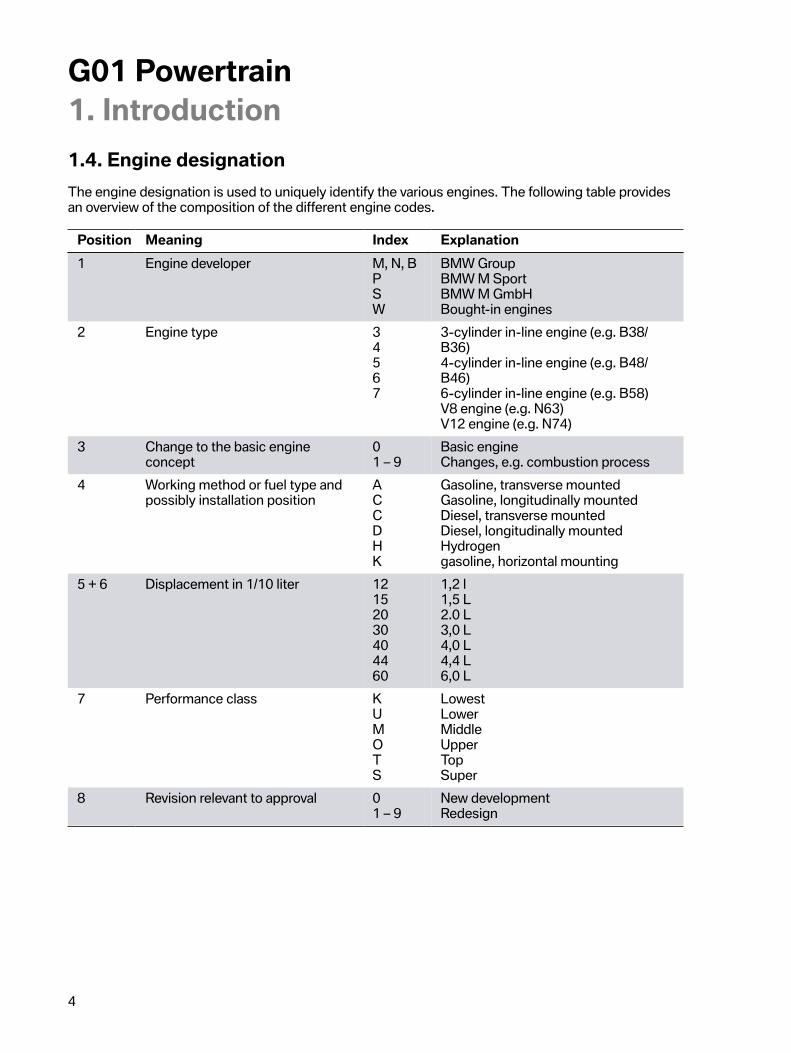
1.4.�Engine�designationThe�engine�designation�is�used�to�uniquely�identify�the�various�engines.�The�following�table�providesan�overview�of�the�composition�of�the�different�engine�codes.
Position Meaning Index Explanation1 Engine�developer M,�N,�B
PSW
BMW�GroupBMW�M�SportBMW�M�GmbHBought-in�engines
2 Engine�type 34567
3-cylinder�in-line�engine�(e.g.�B38/B36)4-cylinder�in-line�engine�(e.g.�B48/B46)6-cylinder�in-line�engine�(e.g.�B58)V8�engine�(e.g.�N63)V12�engine�(e.g.�N74)
3 Change�to�the�basic�engineconcept
01 – 9
Basic�engineChanges,�e.g.�combustion�process
4 Working�method�or�fuel�type�andpossibly�installation�position
ACCDHK
Gasoline,�transverse�mountedGasoline,�longitudinally�mountedDiesel,�transverse�mountedDiesel,�longitudinally�mountedHydrogengasoline,�horizontal�mounting
5 + 6 Displacement�in�1/10 liter 12152030404460
1,2�l1,5�L2.0�L3,0�L4,0�L4,4�L6,0�L
7 Performance�class KUMOTS
LowestLowerMiddleUpperTopSuper
8 Revision�relevant�to�approval 01 – 9
New�developmentRedesign
G01�Powertrain2.�Engines
5
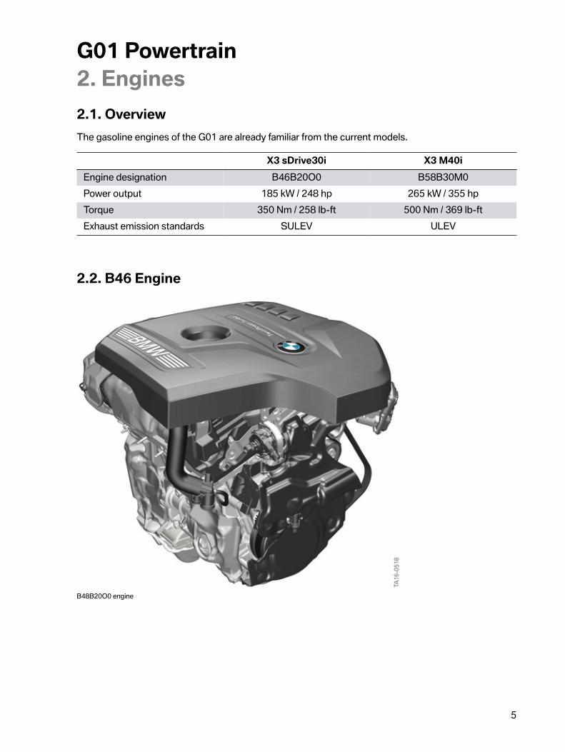
2.1.�OverviewThe�gasoline�engines�of�the�G01�are�already�familiar�from�the�current�models.
X3�sDrive30i X3�M40iEngine�designation B46B20O0 B58B30M0Power�output 185�kW�/�248�hp 265�kW�/�355�hpTorque 350�Nm�/�258�lb-ft 500�Nm�/�369�lb-ftExhaust�emission�standards SULEV ULEV
2.2.�B46�Engine
B48B20O0�engine
G01�Powertrain2.�Engines
6
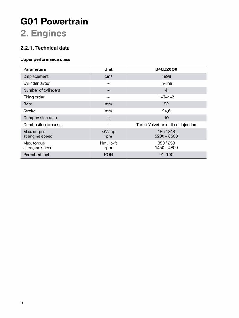
2.2.1.�Technical�data
Upper�performance�class
Parameters Unit B46B20O0Displacement cm³ 1998Cylinder�layout – In-lineNumber�of�cylinders – 4Firing�order – 1–3–4–2Bore mm 82Stroke mm 94,6Compression�ratio ε 10Combustion�process – Turbo-Valvetronic�direct�injectionMax.�outputat�engine�speed
kW�/�hprpm
185�/�2485200�–�6500
Max.�torqueat�engine�speed
Nm�/�lb-ftrpm
350�/�2581450�–�4800
Permitted�fuel RON 91–100

G01�Powertrain2.�Engines
7
Full�load�diagram�B46B20O0�engine
*�740e�iPerformance�vehicle
2.2.2.�Special�features
• Direct�rail�injection�system�with�200�bar�pressure• 4th�generation�Valvetronic• Twin-scroll�turbocharger�with�electrical�wastegate�valve�controller• Intake�air�system�with�integrated�charge�air�cooler• Switchable�coolant�pump

G01�Powertrain2.�Engines
8
• Heat�management�module• Characteristic�map-controlled�oil�pump�with�integrated�vacuum�pump• 8th�generation�Digital�Motor�Electronics�(DME).
2.3.�B58�engine
B58B30M0�engine
2.3.1.�Technical�data
Parameters Unit B58B30M0Displacement cm³ 2998Cylinder�layout – In-lineNumber�of�cylinders – 6Firing�order – 1–5–3–6–2–4Bore mm 82Stroke mm 94,6Compression�ratio ε 11Combustion�method – Turbo-Valvetronic
direct�injection
G01�Powertrain2.�Engines
9
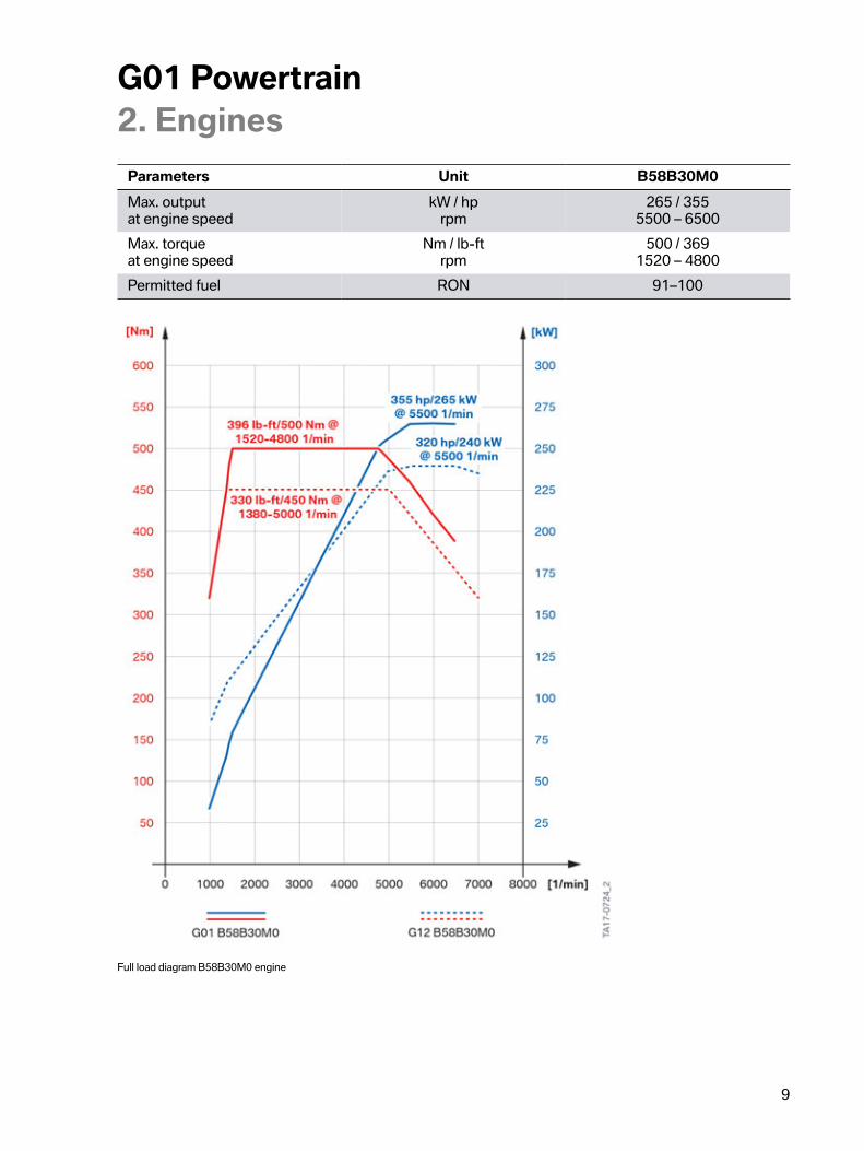
Parameters Unit B58B30M0Max.�outputat�engine�speed
kW�/�hprpm
265�/�3555500�–�6500
Max.�torqueat�engine�speed
Nm�/�lb-ftrpm
500�/�3691520�–�4800
Permitted�fuel RON 91–100
Full�load�diagram�B58B30M0�engine

G01�Powertrain2.�Engines
10
2.3.2.�Special�features
• Direct�rail�injection�system�with�200�bar�pressure• 4th�generation�Valvetronic• Twin-scroll�turbocharger�with�electrical�wastegate�valve�controller• Exhaust�manifold�with�expansion�compensation�elements• Intake�air�system�with�integrated�charge�air�cooler• Heat�management�module• Characteristic�map-controlled�oil�pump�with�integrated�vacuum�pump• 8th�generation�Digital�Motor�Electronics�(DME)

G01�Powertrain2.�Engines
11
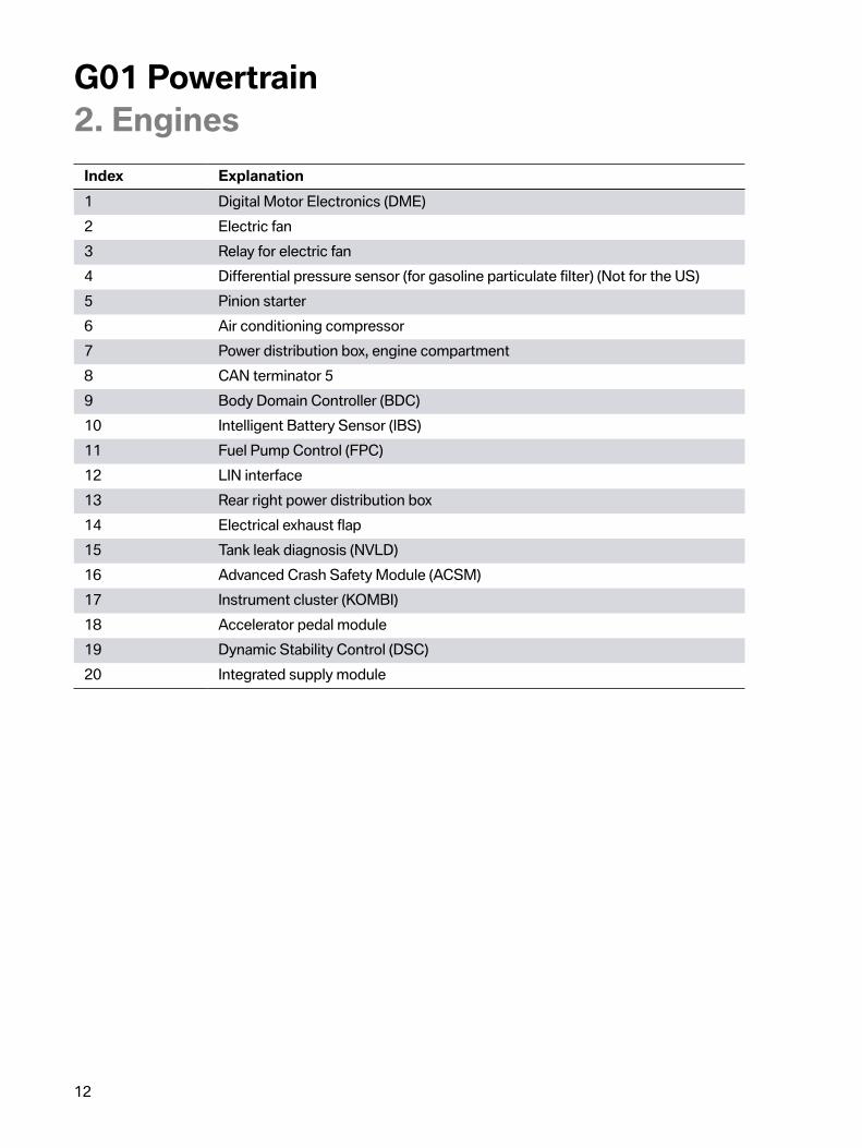
2.4.�System�wiring�diagram
G01�System�wiring�diagram�for�gasoline�engine
G01�Powertrain2.�Engines
12
Index Explanation1 Digital�Motor�Electronics�(DME)2 Electric�fan3 Relay�for�electric�fan4 Differential�pressure�sensor�(for�gasoline�particulate�filter)�(Not�for�the�US)5 Pinion�starter6 Air�conditioning�compressor7 Power�distribution�box,�engine�compartment8 CAN�terminator�59 Body�Domain�Controller�(BDC)10 Intelligent�Battery�Sensor�(IBS)11 Fuel�Pump�Control�(FPC)12 LIN�interface13 Rear�right�power�distribution�box14 Electrical�exhaust�flap15 Tank�leak�diagnosis�(NVLD)16 Advanced�Crash�Safety�Module�(ACSM)17 Instrument�cluster�(KOMBI)18 Accelerator�pedal�module19 Dynamic�Stability�Control�(DSC)20 Integrated�supply�module

G01�Powertrain2.�Engines
13
2.5.�Intake�air�system
2.5.1.�Air�intake�duct
G01�Air�intake�ducts�of�gasoline�engine
Index ExplanationA B46�engineB B58�engine1 Intake�silencer2 Resonator
Resonator
The�pulsating�gas�exchange�noise�of�the�reciprocating�engine�is�damped�in�the�air�intake�duct.Resonators�are�technical�solutions�for�achieving�vehicle-specific�damping�specifications�with�themaximum�air�duct�cross-sections�and�minimum�packaging�space�volume.

G01�Powertrain2.�Engines
14
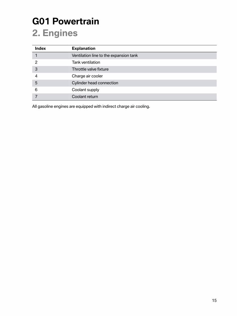
2.5.2.�Charge�air�cooling
B46�engine�intake�system�with�integrated�indirect�charge�air�cooler
G01�Powertrain2.�Engines
15
Index Explanation1 Ventilation�line�to�the�expansion�tank2 Tank�ventilation3 Throttle�valve�fixture4 Charge�air�cooler5 Cylinder�head�connection6 Coolant�supply7 Coolant�return
All�gasoline�engines�are�equipped�with�indirect�charge�air�cooling.
G01�Powertrain3.�Cooling
16
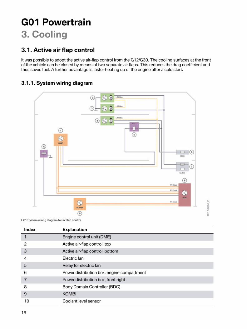
3.1.�Active�air�flap�controlIt�was�possible�to�adopt�the�active�air-flap�control�from�the�G12/G30.�The�cooling�surfaces�at�the�frontof�the�vehicle�can�be�closed�by�means�of�two�separate�air�flaps.�This�reduces�the�drag�coefficient�andthus�saves�fuel.�A�further�advantage�is�faster�heating�up�of�the�engine�after�a�cold�start.
3.1.1.�System�wiring�diagram
G01�System�wiring�diagram�for�air�flap�control
Index Explanation1 Engine�control�unit�(DME)2 Active�air-flap�control,�top3 Active�air-flap�control,�bottom4 Electric�fan5 Relay�for�electric�fan6 Power�distribution�box,�engine�compartment7 Power�distribution�box,�front�right8 Body�Domain�Controller�(BDC)9 KOMBI10 Coolant�level�sensor
G01�Powertrain4.�Fuel�Supply
17
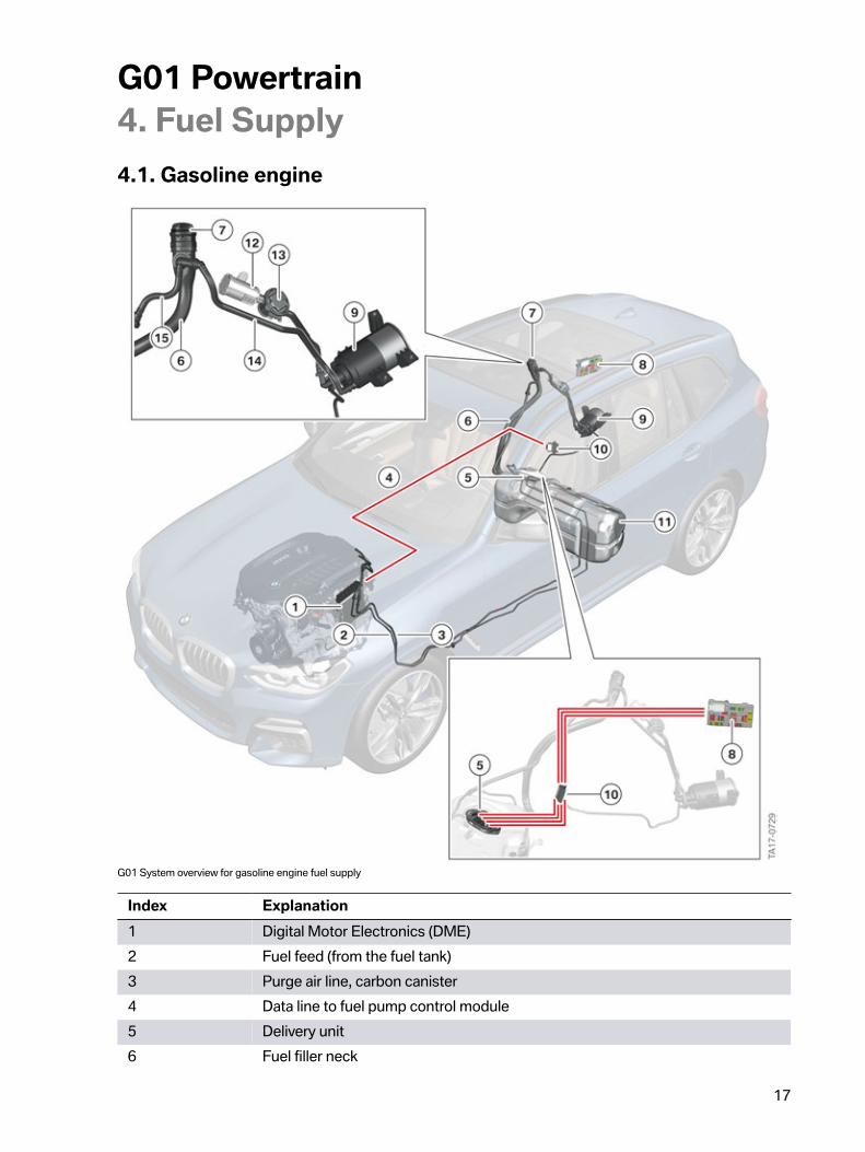
4.1.�Gasoline�engine
G01�System�overview�for�gasoline�engine�fuel�supply
Index Explanation1 Digital�Motor�Electronics�(DME)2 Fuel�feed�(from�the�fuel�tank)3 Purge�air�line,�carbon�canister4 Data�line�to�fuel�pump�control�module5 Delivery�unit6 Fuel�filler�neck
G01�Powertrain4.�Fuel�Supply
18
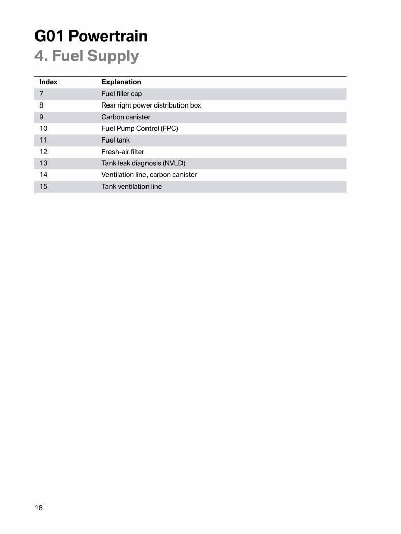
Index Explanation7 Fuel�filler�cap8 Rear�right�power�distribution�box9 Carbon�canister10 Fuel�Pump�Control�(FPC)11 Fuel�tank12 Fresh-air�filter13 Tank�leak�diagnosis�(NVLD)14 Ventilation�line,�carbon�canister15 Tank�ventilation�line
G01�Powertrain5.�Engine�Electrical�System
19
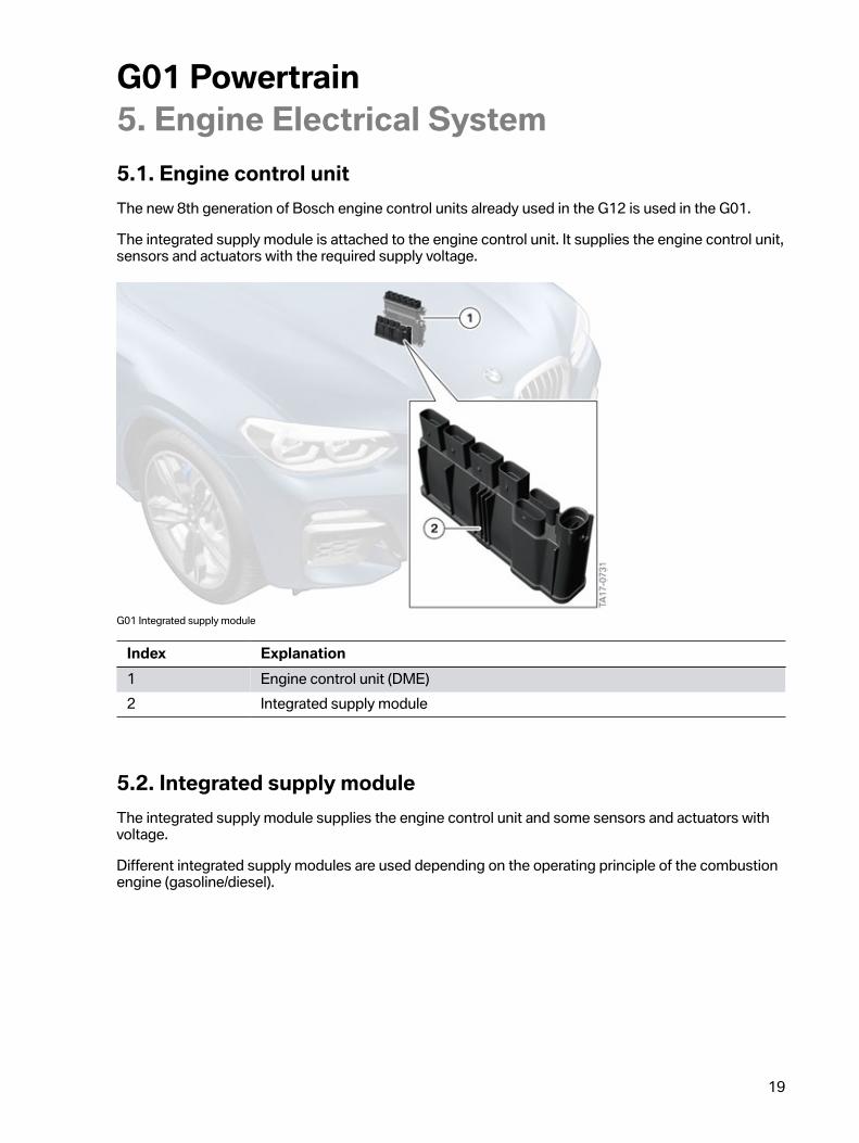
5.1.�Engine�control�unitThe�new�8th�generation�of�Bosch�engine�control�units�already�used�in�the�G12�is�used�in�the�G01.
The�integrated�supply�module�is�attached�to�the�engine�control�unit.�It�supplies�the�engine�control�unit,sensors�and�actuators�with�the�required�supply�voltage.
G01�Integrated�supply�module
Index Explanation1 Engine�control�unit�(DME)2 Integrated�supply�module
5.2.�Integrated�supply�moduleThe�integrated�supply�module�supplies�the�engine�control�unit�and�some�sensors�and�actuators�withvoltage.
Different�integrated�supply�modules�are�used�depending�on�the�operating�principle�of�the�combustionengine�(gasoline/diesel).
G01�Powertrain5.�Engine�Electrical�System
20
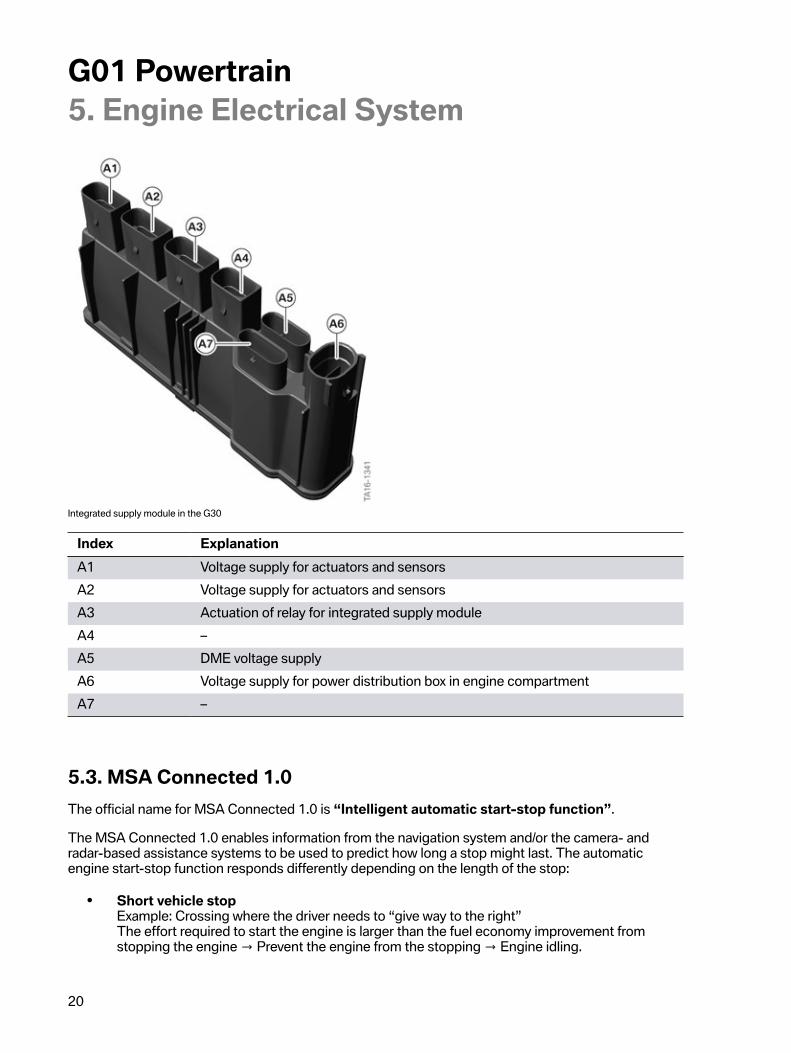
Integrated�supply�module�in�the�G30
Index ExplanationA1 Voltage�supply�for�actuators�and�sensorsA2 Voltage�supply�for�actuators�and�sensorsA3 Actuation�of�relay�for�integrated�supply�moduleA4 –A5 DME�voltage�supplyA6 Voltage�supply�for�power�distribution�box�in�engine�compartmentA7 –
5.3.�MSA�Connected�1.0The�official�name�for�MSA�Connected�1.0�is�“Intelligent�automatic�start-stop�function”.
The�MSA�Connected�1.0�enables�information�from�the�navigation�system�and/or�the�camera-�andradar-based�assistance�systems�to�be�used�to�predict�how�long�a�stop�might�last.�The�automaticengine�start-stop�function�responds�differently�depending�on�the�length�of�the�stop:
• Short�vehicle�stopExample:�Crossing�where�the�driver�needs�to�“give�way�to�the�right”The�effort�required�to�start�the�engine�is�larger�than�the�fuel�economy�improvement�fromstopping�the�engine�→�Prevent�the�engine�from�the�stopping�→�Engine�idling.
G01�Powertrain5.�Engine�Electrical�System
21
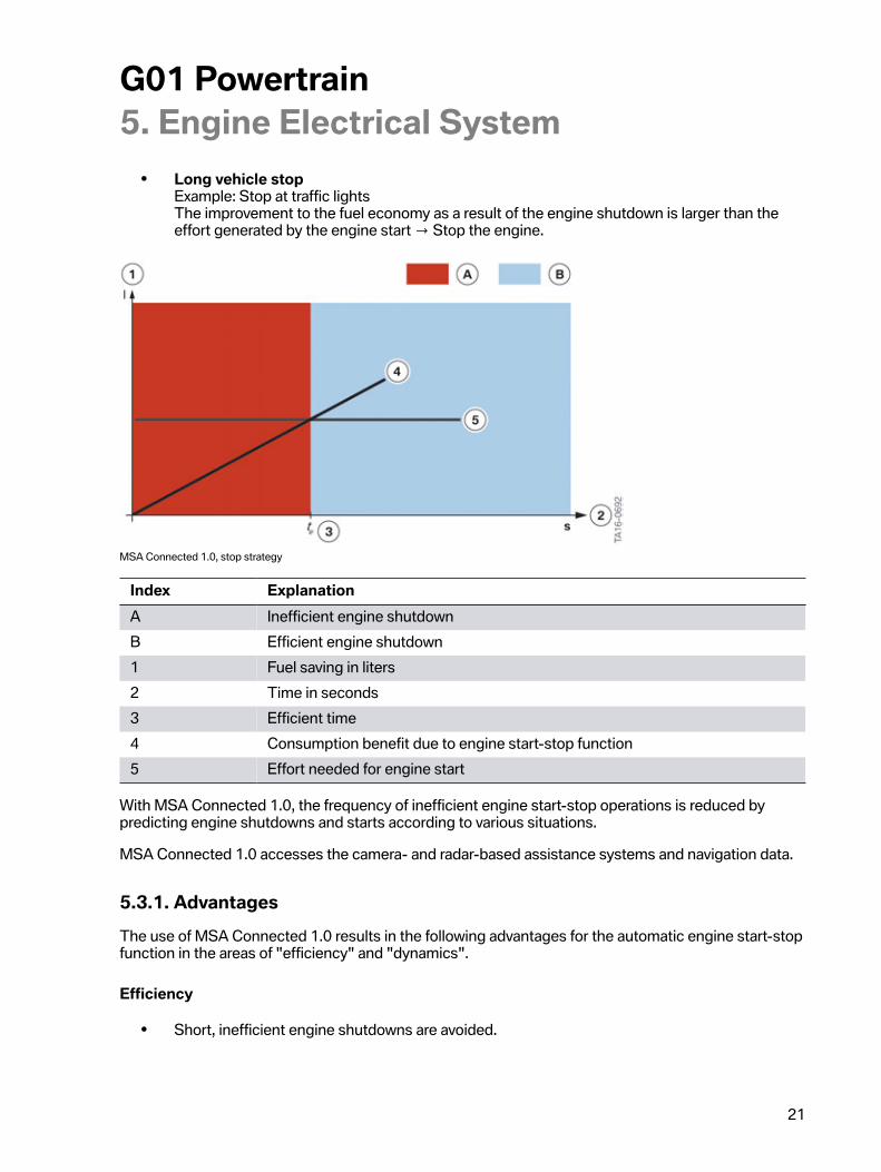
• Long�vehicle�stopExample:�Stop�at�traffic�lightsThe�improvement�to�the�fuel�economy�as�a�result�of�the�engine�shutdown�is�larger�than�theeffort�generated�by�the�engine�start�→�Stop�the�engine.
MSA�Connected�1.0,�stop�strategy
Index ExplanationA Inefficient�engine�shutdownB Efficient�engine�shutdown1 Fuel�saving�in�liters2 Time�in�seconds3 Efficient�time4 Consumption�benefit�due�to�engine�start-stop�function5 Effort�needed�for�engine�start
With�MSA�Connected�1.0,�the�frequency�of�inefficient�engine�start-stop�operations�is�reduced�bypredicting�engine�shutdowns�and�starts�according�to�various�situations.
MSA�Connected�1.0�accesses�the�camera-�and�radar-based�assistance�systems�and�navigation�data.
5.3.1.�AdvantagesThe�use�of�MSA�Connected�1.0�results�in�the�following�advantages�for�the�automatic�engine�start-stopfunction�in�the�areas�of�"efficiency"�and�"dynamics".
Efficiency
• Short,�inefficient�engine�shutdowns�are�avoided.

G01�Powertrain5.�Engine�Electrical�System
22
Dynamic
• The�drive-off�response�is�improved�by�preventing�the�automatic�engine�start-stop�functionfrom�starting�and�stopping�in�MSA�Connected�1.0�situations.
• Drive-off�reminder�“Vehicle�in�front�is�driving�off”.• The�number�“reflex�starts�due�to�the�driver�changing�their�mind”�is�reduced.
5.3.2.�MSA�Connected�1.0�situationsThe�following�MSA�Connected�1.0�situation�is�available�provided�that�the�vehicle�is�equipped�with�thenecessary�sensors�and�systems�described,�depending�on�the�equipment�and/or�country.
Situation MSA�Connected�1.0�actionVehicle�ahead�drives�off If�the�vehicle�detects�that�the�vehicle�in
front�is�moving,�the�engine�is�not�stopped.�Ifthe�vehicle�detects�that�the�vehicle�in�frontis�driving�off�when�the�engine�is�switchedoff,�the�engine�is�then�started.
Traffic�circle/roundabout The�engine�is�not�stopped�when�the�vehicleis�approaching,�is�on�or�has�just�left�a�trafficcircle.�Exception:�The�vehicle�in�front�isstationary�on�the�approach�to�a�traffic�circle.
Residential�crossing The�engine�is�not�switched�off�if�the�vehicleis�right�in�front�of�a�residential�crossing.Exception:�The�vehicle�in�front�is�stationaryon�the�approach�to�a�crossroads�in�aresidential�crossing.
Intention�to�turn The�engine�is�not�switched�off�if�the�vehicleis�at�a�intersection�and�the�system�detectsthat�driver�is�about�to�turn�(turn�indicatorswitched�on).
G01�Powertrain5.�Engine�Electrical�System
23
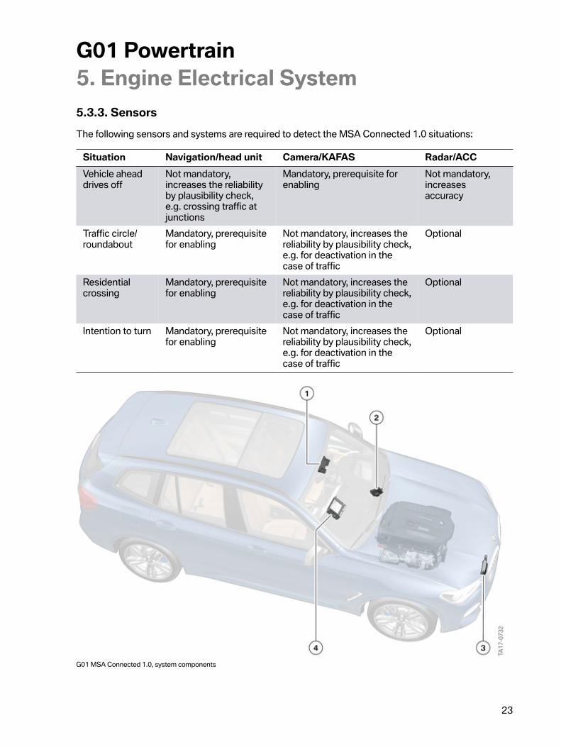
5.3.3.�SensorsThe�following�sensors�and�systems�are�required�to�detect�the�MSA�Connected�1.0�situations:
Situation Navigation/head�unit Camera/KAFAS Radar/ACCVehicle�aheaddrives�off
Not�mandatory,increases�the�reliabilityby�plausibility�check,e.g.�crossing�traffic�atjunctions
Mandatory,�prerequisite�forenabling
Not�mandatory,increasesaccuracy
Traffic�circle/roundabout
Mandatory,�prerequisitefor�enabling
Not�mandatory,�increases�thereliability�by�plausibility�check,e.g.�for�deactivation�in�thecase�of�traffic
Optional
Residentialcrossing
Mandatory,�prerequisitefor�enabling
Not�mandatory,�increases�thereliability�by�plausibility�check,e.g.�for�deactivation�in�thecase�of�traffic
Optional
Intention�to�turn Mandatory,�prerequisitefor�enabling
Not�mandatory,�increases�thereliability�by�plausibility�check,e.g.�for�deactivation�in�thecase�of�traffic
Optional
G01�MSA�Connected�1.0,�system�components
G01�Powertrain5.�Engine�Electrical�System
24
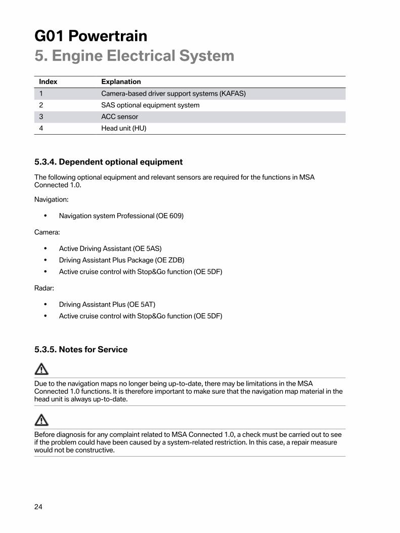
Index Explanation1 Camera-based�driver�support�systems�(KAFAS)2 SAS�optional�equipment�system3 ACC�sensor4 Head�unit�(HU)
5.3.4.�Dependent�optional�equipmentThe�following�optional�equipment�and�relevant�sensors�are�required�for�the�functions�in�MSAConnected�1.0.
Navigation:
• Navigation�system�Professional�(OE 609)
Camera:
• Active�Driving�Assistant�(OE 5AS)• Driving�Assistant�Plus�Package�(OE ZDB)• Active�cruise�control�with�Stop&Go�function�(OE 5DF)
Radar:
• Driving�Assistant�Plus�(OE 5AT)• Active�cruise�control�with�Stop&Go�function�(OE 5DF)
5.3.5.�Notes�for�Service
Due�to�the�navigation�maps�no�longer�being�up-to-date,�there�may�be�limitations�in�the�MSAConnected�1.0�functions.�It�is�therefore�important�to�make�sure�that�the�navigation�map�material�in�thehead�unit�is�always�up-to-date.
Before�diagnosis�for�any�complaint�related�to�MSA�Connected�1.0,�a�check�must�be�carried�out�to�seeif�the�problem�could�have�been�caused�by�a�system-related�restriction.�In�this�case,�a�repair�measurewould�not�be�constructive.
G01�Powertrain6.�Automatic�Transmission
25
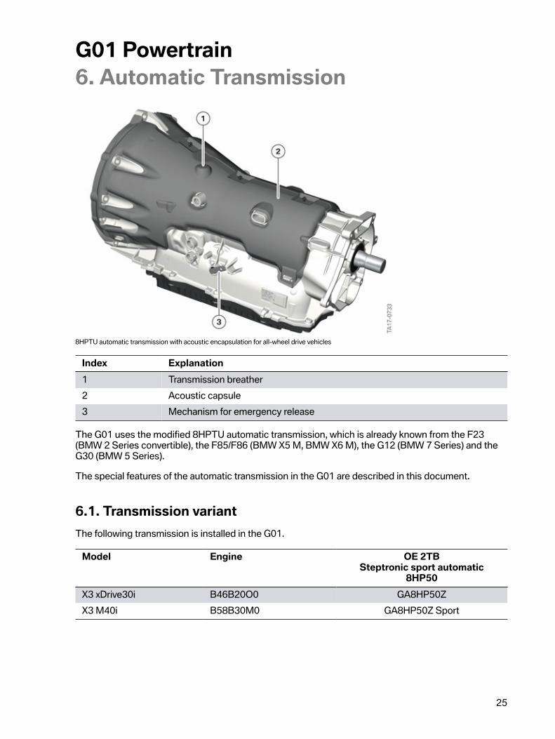
8HPTU�automatic�transmission�with�acoustic�encapsulation�for�all-wheel�drive�vehicles
Index Explanation1 Transmission�breather2 Acoustic�capsule3 Mechanism�for�emergency�release
The�G01�uses�the�modified�8HPTU�automatic�transmission,�which�is�already�known�from�the�F23(BMW 2�Series�convertible),�the�F85/F86�(BMW X5 M,�BMW X6 M),�the�G12�(BMW 7�Series)�and�theG30�(BMW 5�Series).
The�special�features�of�the�automatic�transmission�in�the�G01�are�described�in�this�document.
6.1.�Transmission�variantThe�following�transmission�is�installed�in�the�G01.
Model Engine OE�2TBSteptronic�sport�automatic
8HP50X3�xDrive30i B46B20O0 GA8HP50ZX3�M40i B58B30M0 GA8HP50Z�Sport

G01�Powertrain6.�Automatic�Transmission
26
6.2.�Special�featuresThe�following�further�developments�made�it�possible�to�increase�the�comfort,�dynamics�and�efficiencyof�the�revamped�8-speed�automatic�transmission:
• Improved�driving�comfort�through�hot-end�decoupling�of�the�rotational�imbalance�of�theengine�by�means�of�a�centrifugal�pendulum.
• Improved�shifting�comfort�through�slightly�increased�gear�steps�(2�modified�planetary�gearsets).
• Increased�efficiency�through�optimum�gear�spread�and�gear�stepping.• Reduction�of�vehicle-specific�insulation�measures�due�to�acoustic�encapsulation�on�the
transmission.• Functional�enhancements�in�the�area�of�ConnectedShift.• Enhanced�customer�experience�due�to�new�operating�possibilities�with�the�driving�experience
switch�or�shift�paddles.
6.3.�DesignationThe�following�table�provides�an�overview�of�the�composition�of�the�different�transmission�codes:
Position Meaning Index Explanation1 Designation G Transmission2 Type�of�transmission A Automatic�transmission3 Number�of�gears 6
86�forward�gears8�forward�gears
G01�Powertrain6.�Automatic�Transmission
27
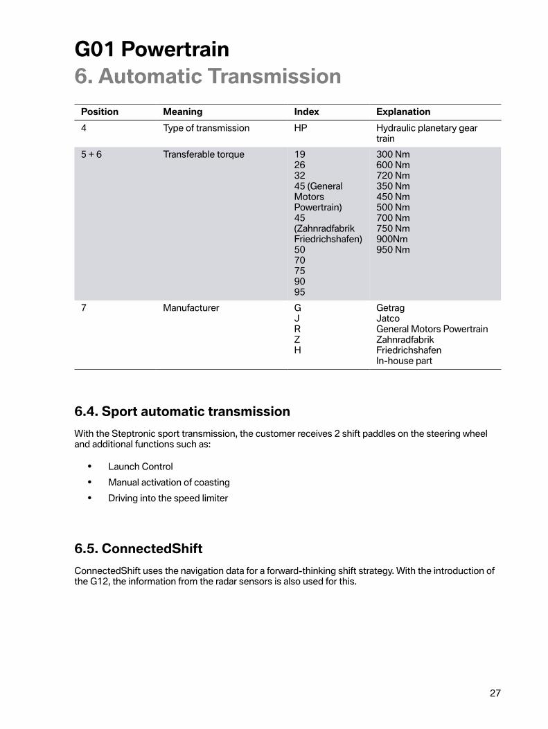
Position Meaning Index Explanation4 Type�of�transmission HP Hydraulic�planetary�gear
train5�+�6 Transferable�torque 19
263245�(GeneralMotorsPowertrain)45(ZahnradfabrikFriedrichshafen)5070759095
300�Nm600�Nm720�Nm350�Nm450�Nm500�Nm700�Nm750�Nm900Nm950�Nm
7 Manufacturer GJRZH
GetragJatcoGeneral�Motors�PowertrainZahnradfabrikFriedrichshafenIn-house�part
6.4.�Sport�automatic�transmissionWith�the�Steptronic�sport�transmission,�the�customer�receives�2�shift�paddles�on�the�steering�wheeland�additional�functions�such�as:
• Launch�Control• Manual�activation�of�coasting• Driving�into�the�speed�limiter
6.5.�ConnectedShiftConnectedShift�uses�the�navigation�data�for�a�forward-thinking�shift�strategy.�With�the�introduction�ofthe�G12,�the�information�from�the�radar�sensors�is�also�used�for�this.

G01�Powertrain6.�Automatic�Transmission
28
6.6.�Configuration�options
6.6.1.�Influence�of�the�driving�experience�switchMany�drive�variants�have�a�SPORT�PLUS�mode�in�order�to�support�sporty�driving�with�more�powerfulengines.�The�shift�characteristics�are�adapted�as�follows�in�the�SPORT�PLUS�mode:
• Sharper�design�of�downshifts�on�braking• Further�increase�of�the�engine�speed�in�the�direction�of�maximum�power.
Mode X3�xDrive30iX3�M40i
SPORT�PLUS •SPORT •COMFORT •ECO�PRO •
6.7.�Transmission�emergency�releaseIn�the�event�of�a�breakdown,�emergency�release�of�the�automatic�transmission�is�possible�in�2�differentways.
• Mechanical�transmission�emergency�release.• Electronic�transmission�emergency�release.

G01�Powertrain6.�Automatic�Transmission
29
6.8.�Towing
G01�Towing
Index ExplanationA Towing�on�both�vehicle�axlesB Towing�on�the�rear�vehicle�axleC Recovery�on�a�transport�deck
Towing�of�the�G01�with�automatic�transmission�on�the�driven�vehicle�axle�is�not�permitted.�Limitedtime-�and�speed-dependent�towing�would�not�technically�damage�the�automatic�transmission,�butpermanent�release�of�the�parking�lock�cannot�be�guaranteed�due�to�the�changed�mechanical�andelectronic�transmission�emergency�release.�Sudden�engagement�of�the�parking�lock�during�a�towingoperation�on�the�driven�vehicle�axle�can�lead�to�damage�to�the�vehicle�and�to�serious�accidents.
G01�Powertrain6.�Automatic�Transmission
30
6.9.�System�wiring�diagram
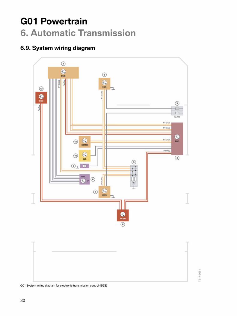
G01�System�wiring�diagram�for�electronic�transmission�control�(EGS)

G01�Powertrain6.�Automatic�Transmission
31
Index Explanation1 Digital�Motor�Electronics�(DME)2 Electronic�transmission�control�(EGS)3 Power�distribution�box,�front�right4 Body�Domain�Controller�(BDC)5 CAN�terminator�56 Advanced�Crash�Safety�Module�(ACSM)7 Gear�selector�switch�(GWS)8 Accelerator�pedal�module9 Brake�light�switch10 Steering�column�switch�cluster11 Instrument�cluster�(KOMBI)12 Dynamic�Stability�Control�(DSC)
G01�Powertrain7.�Four-Wheel�Drive
32
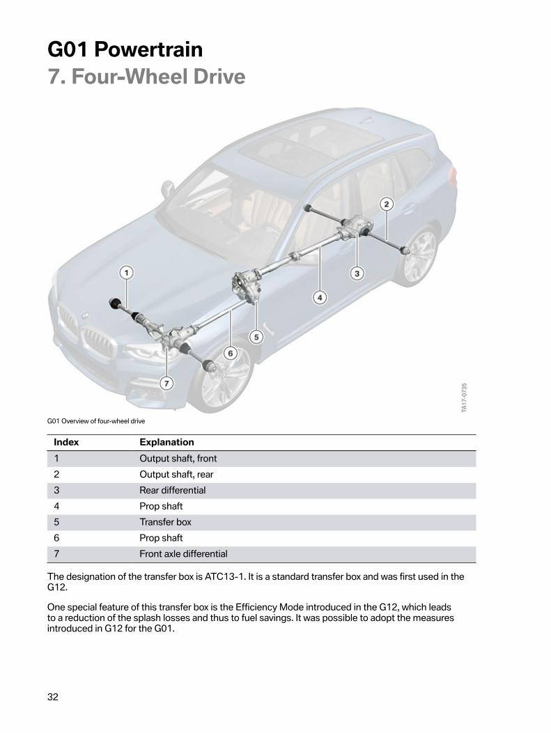
G01�Overview�of�four-wheel�drive
Index Explanation1 Output�shaft,�front2 Output�shaft,�rear3 Rear�differential4 Prop�shaft5 Transfer�box6 Prop�shaft7 Front�axle�differential
The�designation�of�the�transfer�box�is�ATC13-1.�It�is�a�standard�transfer�box�and�was�first�used�in�theG12.
One�special�feature�of�this�transfer�box�is�the�Efficiency�Mode�introduced�in�the�G12,�which�leadsto�a�reduction�of�the�splash�losses�and�thus�to�fuel�savings.�It�was�possible�to�adopt�the�measuresintroduced�in�G12�for�the�G01.

G01�Powertrain7.�Four-Wheel�Drive
33
7.1.�System�wiring�diagram
G01�System�wiring�diagram�xDrive
Index Explanation1 Dynamic�Stability�Control�(DSC)2 VTG�control�unit3 Power�distribution�box,�front�right4 Body�Domain�Controller�(BDC)5 Advanced�Crash�Safety�Module�(ACSM)6 Head�unit7 Central�Information�Display�(CID)

Bayerische�Motorenwerke�AktiengesellschaftHändlerqualifizierung�und�TrainingRöntgenstraße�785716�Unterschleißheim,�Germany