Embed Size (px)
Citation preview

Technical�training.Product�information.
BMW�Service
F85/F86�Complete�Vehicle

General�informationSymbols�used
The�following�symbol�is�used�in�this�document�to�facilitate�better�comprehension�or�to�draw�attentionto�very�important�information:
Contains�important�safety�information�and�information�that�needs�to�be�observed�strictly�in�order�toguarantee�the�smooth�operation�of�the�system.
Information�status�and�national-market�versions
BMW�Group�vehicles�meet�the�requirements�of�the�highest�safety�and�quality�standards.�Changesin�requirements�for�environmental�protection,�customer�benefits�and�design�render�necessarycontinuous�development�of�systems�and�components.�Consequently,�there�may�be�discrepanciesbetween�the�contents�of�this�document�and�the�vehicles�available�in�the�training�course.
This�document�basically�relates�to�the�European�version�of�left�hand�drive�vehicles.�Some�operatingelements�or�components�are�arranged�differently�in�right-hand�drive�vehicles�than�shown�in�thegraphics�in�this�document.�Further�differences�may�arise�as�the�result�of�the�equipment�specification�inspecific�markets�or�countries.
Additional�sources�of�information
Further�information�on�the�individual�topics�can�be�found�in�the�following:
• Owner's�Handbook• Integrated�Service�Technical�Application.
Contact:�[email protected]
©2014�BMW�AG,�Munich
Reprints�of�this�publication�or�its�parts�require�the�written�approval�of�BMW�AG,�Munich
The�information�contained�in�this�document�forms�an�integral�part�of�the�technical�training�of�theBMW�Group�and�is�intended�for�the�trainer�and�participants�in�the�seminar.�Refer�to�the�latest�relevantinformation�systems�of�the�BMW�Group�for�any�changes/additions�to�the�technical�data.
Information�status:�November�2014BV-72/Technical�Training

F85/F86�Complete�VehicleContents1. Introduction.............................................................................................................................................................................................................................................1
1.1. M�history..............................................................................................................................................................................................................................11.2. F85�X5�M�vehicle�outline�description....................................................................................................................................21.3. F86�X6�M�vehicle�outline�description....................................................................................................................................4
2. Technical�Data....................................................................................................................................................................................................................................62.1. Comparison�of�E70�M/E71�M�with�F85/F86..............................................................................................................62.2. BMW�EfficientDynamics�measures..........................................................................................................................................7
3. Body......................................................................................................................................................................................................................................................................83.1. Exterior�trim.................................................................................................................................................................................................................... 8
3.1.1. Front..........................................................................................................................................................................................................83.1.2. Side.........................................................................................................................................................................................................103.1.3. Rear........................................................................................................................................................................................................123.1.4. Underbody�and�thermal�protection.....................................................................................................14
3.2. Interior..................................................................................................................................................................................................................................153.2.1. Driving�area�and�steering�wheel...............................................................................................................153.2.2. M�sports�seat.........................................................................................................................................................................163.2.3. Doors�and�strips................................................................................................................................................................17
4. Engine/Powertrain..................................................................................................................................................................................................................184.1. M�TwinPower�turbo�engine�S63B44T2.........................................................................................................................18
4.1.1. S63B44T2�engine,�comparison�of�S63B44O0�engine/S63B44T0engine.................................................................................................................................................................................................19
4.1.2. Intake�manifold.....................................................................................................................................................................204.1.3. Oil�supply......................................................................................................................................................................................214.1.4. Crankshaft�drive.................................................................................................................................................................224.1.5. Crankcase,�cylinder�head�and�timing�drive..............................................................................224.1.6. Exhaust�turbochargers............................................................................................................................................224.1.7. Catalytic�converter.........................................................................................................................................................224.1.8. Exhaust�system...................................................................................................................................................................234.1.9. Vacuum�supply.....................................................................................................................................................................244.1.10. Fuel�preparation................................................................................................................................................................. 244.1.11. Cooling�(engine,�engine�oil,�charge�air,�ARS�(Dynamic�Drive)).................. 254.1.12. Engine�electrical�system...................................................................................................................................... 374.1.13. Service�information.......................................................................................................................................................43
4.2. Power�transmission........................................................................................................................................................................................434.2.1. M�automatic�transmission..................................................................................................................................444.2.2. Axle�drive�and�transfer�box...............................................................................................................................494.2.3. Flexible�disc,�Drive�shaft�and�output�shafts........................................................................... 514.2.4. Service�information.......................................................................................................................................................52

F85/F86�Complete�VehicleContents5. Chassis/Driving�Dynamics�Systems.....................................................................................................................................................53
5.1. Axles.......................................................................................................................................................................................................................................535.1.1. Front�axle.......................................................................................................................................................................................535.1.2. Steering........................................................................................................................................................................................... 535.1.3. Rear�axle.........................................................................................................................................................................................55
5.2. Brakes,�wheels�and�tires........................................................................................................................................................................555.2.1. Brakes.................................................................................................................................................................................................555.2.2. Wheels/tires...............................................................................................................................................................................57
5.3. Driving�dynamics�systems..................................................................................................................................................................585.3.1. Vertical�Dynamics�Management.............................................................................................................. 585.3.2. Transverse�dynamics�management....................................................................................................605.3.3. Longitudinal�dynamics�management...............................................................................................60
6. Vehicle�Electr.�Syst/On-board�Info..........................................................................................................................................................616.1. F85/F86�vehicle�electrical�system..........................................................................................................................................616.2. On-board�information................................................................................................................................................................................. 64
6.2.1. M�instrument�cluster..................................................................................................................................................646.2.2. M�Head‐Up�display�(option�SA�610).................................................................................................666.2.3. M�Drive�menu........................................................................................................................................................................ 67
6.3. Active�Sound�Design�(ASD)............................................................................................................................................................. 69
7. Equipment�Overview..........................................................................................................................................................................................................707.1. Standard�equipment�from�the�BMW�X5�and�X6�optional�equipment�range...........707.2. M�exclusive�standard�equipment..............................................................................................................................................707.3. M�exclusive�optional�equipment................................................................................................................................................70

F85/F86�Complete�Vehicle1.�Introduction
1
The�BMW�M�family�is�being�enhanced�with�the�addition�of�the�F85�(BMW�X5�M)�and�F86�(BMW�X6�M)vehicle�types.�The�F85�and�F86�replace�the�successful�E70�M�and�E71�M�vehicles�and�also�continuethe�typical�M�driving�experience�in�the�Sports�Activity�Vehicle/Sports�Activity�Coupé�segment.�As�isalready�the�case�with�the�E70�M�and�E71�M,�the�F85�and�F86�are�equipped�with�the�M�TwinPowerturbo�engine,�M�Sport�automatic�transmission,�xDrive,�Dynamic�Performance�Control,�Dynamic�Drive,Vertical�Dynamics�Management�(VDM)�and�M�Servotronic.
The�new�BMW�X5�M/BMW�X6�M�will�be�launched�onto�the�market�in�the�first�quarter�of�2015.
1.1.�M�historyIn�1972�the�then�BMW�Motorsport�started�out�with�the�legendary�M1.�For�over�40�years�today's�BMWM�GmbH�has�been�developing�BMW�M�vehicles�with�a�motorsport�pedigree�based�on�the�standardproduction�models.
The�typical�M�driving�experience�was�also�made�to�come�alive�for�the�first�time�in�the�Sports�ActivityVehicle/Sports�Activity�Coupé�segment�in�July�2009.�The�E70�M�and�E71�M�were�the�first�M�vehicleswith�M�TwinPower�turbo�engine,�M�Sport�automatic�transmission,�xDrive,�Dynamic�PerformanceControl,�Dynamic�Drive�and�run-flat�tires.
E70�M�and�E71�M

F85/F86�Complete�Vehicle1.�Introduction
2
1.2.�F85�X5�M�vehicle�outline�description
F85�X5�M
• Design�and�aerodynamics:�5-door�high-performance�sports�activity�vehicle�(SAV).M-specific�characteristics�in�front,�side�and�rear�area.�Unique�aerodynamic�designin�front,�side�and�rear�area�and�vehicle�underbody.
• Engine/Transmission:�4.4-liter�8-cylinder�Turbo-Valvetronic�direct�injection�engine.Even�more�powerful�and�even�more�spontaneous,�linear�power�development.�Choice�of�threeengine�dynamics�control�programs.�Even�faster,�more�precise�gear�changes.�M-specificgearshift�characteristics�with�BMW�M�8-speed�automatic�transmission�variant�(with�Drivelogicprogram).�Dynamic�Performance�Control�(QMVH)�for�even�better�propulsion�power�distributionon�the�rear�axle�and�increased�driving�safety.
• Engine�sound:�Distinctly�sporty�in�the�lower�and�upper�engine�speed�and�power�rangesand�a�more�emotive�starting�sound.
• Steering:�Direct�and�precise�with�M�Servotronic.�M�leather�steering�wheel�includingM�gearshift�paddles�and�M�Mode�buttons.
• Chassis�and�suspension/driving�dynamics�setup:�Sporty�suspension,�without�excessivelyhard�running�characteristics�even�in�sport�mode.�Increased�driving�precision�thanks�to�sportilyoptimized�interaction�of�steering,�suspension�and�damping.�M�Dynamic�Mode�(MDM)�insteadof�Dynamic�Traction�Control�(DTC).�Rear-biased�setup�of�xDrive�for�a�sporty�driving�style�inMDM�and�DSC-OFF�mode.

F85/F86�Complete�Vehicle1.�Introduction
3
• Seating�comfort:�M�sports�seat�including�M�logo�and�high-quality�upholstery�in�BMWIndividual�Merino�leather.
• Ergonomics,�interior�equipment:�BMW�Individual�Merino�leather,�M�instrument�cluster,M�Drive�menu,�M�head‐up�display�with�M�direction�on�start-up,�M�fit,�M-specific�decorativestrips,�M�footrest�and�sill�trims.
• Vehicle�electrical�system:�LED�light�technology�for�headlights�and�fog�lights.HiFi�loudspeaker�system�for�maximum�listening�pleasure.�Active�Sound�DesignASD�for�M-specific�engine�sound�in�the�vehicle�interior.

F85/F86�Complete�Vehicle1.�Introduction
4
1.3.�F86�X6�M�vehicle�outline�description
F86�X6�M
• Design�and�aerodynamics:�5-door�high-performance�sports�activity�coupé�(SAC).M-specific�characteristics�in�front,�side�and�rear�area.�Unique�aerodynamic�design�in�front,side�and�rear�area�and�vehicle�underbody.
• Engine/Transmission:�4.4-liter�8-cylinder�Turbo-Valvetronic�direct�injection�engine.Even�more�powerful�and�even�more�spontaneous,�linear�power�development.�Choice�of�threeengine�dynamics�control�programs.�Even�faster,�more�precise�gear�changes.�M-specificgearshift�characteristics�with�BMW�M�8-speed�automatic�transmission�variant�(with�Drivelogicprogram).�Dynamic�Performance�Control�(QMVH)�for�even�better�propulsion�power�distributionon�the�rear�axle�and�increased�driving�safety.
• Engine�sound:�Distinctly�sporty�character�in�the�lower�and�upper�engine�speed�and�powerranges�and�a�more�emotive�starting�sound.
• Steering:�Direct�and�precise�with�M�Servotronic.�M�leather�steering�wheel�includingM�gearshift�paddles�and�M�Mode�buttons.
• Chassis�and�suspension/driving�dynamics�setup:�Sport�suspension,�without�excessivelyhard�running�characteristics�even�in�sport�mode.�Increased�driving�precision�thanks�to�sportilyoptimized�interaction�of�steering,�suspension�and�damping.�M�Dynamic�Mode�(MDM)�insteadof�Dynamic�Traction�Control�(DTC).�Rear-biased�setup�of�xDrive�for�a�sporty�driving�style�inMDM�and�DSC-OFF�mode.
F85/F86�Complete�Vehicle1.�Introduction
5
• Seating�comfort:�M�sports�seat�including�M�logo�and�high-quality�upholstery�in�BMWIndividual�Merino�leather.
• Ergonomics,�interior�equipment:�BMW�Individual�Merino�leather,�M�instrument�cluster,M�Drive�menu,�M�head‐up�display�with�M�direction�on�start-up,�M�fit,�M-specific�decorativestrips,�M�footrest�and�sill�trims.
• Vehicle�electrical�system:�LED�light�technology�for�headlights�and�fog�lights.HiFi�loudspeaker�system�for�maximum�listening�pleasure.�Active�Sound�Design�(ASD)for�M-specific�engine�sound�in�the�vehicle�interior.

F85/F86�Complete�Vehicle2.�Technical�Data
6
2.1.�Comparison�of�E70�M/E71�M�with�F85/F86Designation Unit E70�M E71�M F85 F86Engine�series S63B44O0 S63B44O0 S63B44T2 S63B44T2Engine�control MSD85.1 MSD85.1 MEVD
17.2.HMEVD17.2.H
Transmission�type�designation 6HP26S 6HP26S M8HP75 M8HP75Length [mm] 4851 4876 4894 4923Width [mm] 1994 1983 1985 1989Height [mm] 1764 1684 1717 1689Number�of�seats 5 4 5 5Luggagecompartmentvolume
[liters](cubic�feet)
620�–�1750 570�-�1450 650�-�1870(35.8�-�76.7)
550�-�1525(26.6�-�59.7)
Top�speed [km/h](mph)
250*/156* 250*/156* 250*/156* 250*/156*
Acceleration0�-�60 mph
[s] 4.7 4.5 4.0 4.0
1000�mstationary�start
[s] 23.5 23.5 22.6 22.6
Nominal�enginepowerat�engine�speed
[kW�/�bhp][rpm]
408/5556000
408/5556000
423/5676000�-�6500
423/5676000�-�6500
Power-to-weightratio�(DIN)
[kg/kW] 5.6 5.6 5.4 5.4
Torque�at�speed [Nm](lb-ft)[rpm]
680�(500)1500�-�5650
680�(500)1500�-�5650
750�(553)2200�-�5000
750�(553)2200�-�5000
Aerodynamicscx�(drag�coefficient) 0.38 0.38 0.38 0.37A�(frontal�area) [m2] 2.90 2.85 2.93 2.89
cx�x�A�(drag) [m2] 1.10 1.08 1.11 1.07
Curb�weightUS [kg](lbs) 2435�(5368) 2415�(5324) 2386�(5260) 2352�(5185)Rear�axle�loadsection,�empty(DIN)
[%] 47.9 47.2 48.4 47.3
Load�capacity [kg]�(lbs) 600�(1322) 600�(1322) 695�(1532) 685�(1510)Permissible�grossweight
[kg]�(lbs) 2935�(6471) 2840�(6261) 2971�(6550) 2951�(6505)
Permissible�towedweight
[kg] 3000 3000 2970 2950

F85/F86�Complete�Vehicle2.�Technical�Data
7
Designation Unit E70�M E71�M F85 F86Fuel�consumption [l/100 km] 13.9 13.9 11.1 11.1Approx.�fuel�tankcapacity
[l](US�gal) 85�(22.4) 85�(22.4) 85�(22.4) 85�(22.4)
CO2�emissions [grams�perkilometer]
325 325 258 258
Exhaust�emission�standards LEV�II LEV�II ULEV�2 ULEV�2
*�Electronically�regulated.
2.2.�BMW�EfficientDynamics�measures• TwinPower�Turbo�technology• Gasoline�direct�fuel�injection�with�Valvetronic• Automatic�engine�start-stop�function• Efficient�8-speed�M�automatic�transmission• M�Servotronic�(EPS)• Use�of�ancillary�components�as�required�(air�conditioning�compressor)• Brake�energy�regeneration

F85/F86�Complete�Vehicle3.�Body
8
3.1.�Exterior�trim
3.1.1.�Front
Bumper,�front
The�single-piece�M-specific�bumper�panel�is�extensively�identical�in�design�for�the�F85�and�F86�andhas�M-specific�flaps�for�reducing�lift�on�the�front�axle.�It�is,�including�the�standard�ultrasonic�sensors�forPark�Distance�Control�(PDC)�and�the�number�plate�baseplate,�painted�to�match�the�exterior�body�color.LED�technology�fog�lights�are�fitted�as�standard.�The�grilles�have�a�black�grained�finish.The�optional�Surround�View�camera�and�the�ultrasonic�sensor�for�the�Parking�Manoeuvring�Assistant(PMA)�is�integrated�similarly�to�the�F15/F16�production�vehicle�at�side�front.
Unlike�the�F15/F16,�on�the�F85/F86�there�is�no�air�curtain�integrated�in�the�front�bumper�panel�andthe�adjoining�wheel�arch�panel.�The�air�breather�contributes,�together�with�the�gill,�the�underbodypanelling,�a�rear�spoiler�on�the�F86�and�the�exterior�mirrors,�to�the�aerodynamic�concept�of�theF85/F86.
The�F85/F86�is�equipped�as�standard�with�Xenon�headlights�and�LED�fog�lights.
F85/F86�front�view
Radiator�(kidney)�grille
The�frame�and�the�double-rib�kidney�bars�of�the�BMW�M�radiator�grille�have�black�high-gloss�struts�asstandard�for�the�F85/F86.
Cooling�air�routing
The�new�air�duct�is�identical�for�the�F85�and�F86.�New�cooling�air�routing�for�all�radiators/coolers:multifunction�air�routing,�air�duct�for�brakes,�air�duct�for�auxiliary�radiator�and�air�duct�with�additionalair�guide�for�the�additional�low-temperature�cooler.
The�air�inlet�areas�for�the�required�cooling�air�on�the�front�bumper�panel�have�been�enlarged�andoptimized�in�such�a�way�that�the�F85/F86�has�50 %�more�inlet�area�for�cooling�air�than�the�E7x�M.This�measure�has�positive�influence�on�the�cooling�power�for�charge�air�cooling,�A/C�condensercooling,�engine�cooling,�engine�oil�cooling,�transmission�cooling�and�oil�cooling�of�the�ARS�system.

F85/F86�Complete�Vehicle3.�Body
9
Front�end
The�air�intake�duct�and�the�mounting�arrangement�for�the�intake�silencer�are�identical�for�the�F85�andF86.�An�aluminium�extruded�section�cross-member,�including�two�additional�brackets�for�the�intakesilencer,�is�installed�to�accommodate�the�now�body-mounted�intake�silencer.
F85/F86�M�air�intake�duct�and�intake�silencer

F85/F86�Complete�Vehicle3.�Body
10
3.1.2.�Side
Fenders
While�sharing�the�same�basic�design,�the�front�fenders�on�the�F85�and�F86�differ�from�each�othergeometrically.�Distinctive�design�features�include�the�so-called�M�gills�and�the�X5�M/X6�M�modelinscriptions�on�the�front�left�and�right�fenders.�In�addition,�for�the�first�time�in�a�BMW�X�M�vehicle�theair�breathers�are�used�on�the�left�and�right�in�the�fenders,�which�are�integrated�in�the�typical�M�gill.
F85/F86�M�gill�elements�with�integrated�air�breather
Exterior�mirrors
The�exterior�mirrors�have�an�M-specific�design�with�a�double-rib�character.�They�are�heated�andelectrochromic�as�standard,�and�have�a�memory�and�fold-in�function�as�well�as�an�automatic�parkingfunction�for�the�passenger�side�mirror.�The�turn�indicators�are�integrated�in�the�exterior�mirror�caps.
Wheel�arch�trims/rims
The�painted�front�and�rear�wheel�arch�trims�on�the�F85�and�F86�have�the�same�design�as�the�wheelarch�trims�on�the�F15/F16�with�M�Sport�package.
Side�sills
The�M�side�sills�on�the�F85�and�F86�have�the�same�design�as�the�F15/F16�side�sill�withM�Sport�package.
Trim�strips
All�the�trim�strips,�with�the�exception�of�the�roof�trim�strips,�come�in�BMW�Individual�high-glossShadow�Line.
Roof�trim�strips
The�roof�trim�strips�on�the�F85�come�in�matt�black�while�those�on�the�F86�are�painted�in�the�bodycolor.

F85/F86�Complete�Vehicle3.�Body
11
F85
F85�side�view
F86
F86�side�view

F85/F86�Complete�Vehicle3.�Body
12
3.1.3.�Rear
Exhaust�tailpipes
The�four�round�exhaust�tailpipes,�which�are�typical�of�BMW�M�vehicles,�are�a�distinctive�design�feature.
Trailer�tow�hitch
A�specifically�adapted�trailer�tow�hitch�is�used�on�the�F85/F86.
F85�rear
F85�rear�view
The�M-specific�bumper�panel�is�designed�in�three�pieces.�The�panel�of�the�upper�bumper�with�PDC�ispainted�to�match�the�body�exterior�color.�The�lower�diffuser�is�painted�to�match�the�body�exterior�colorapart�from�the�black�grained�finish�center�grille.

F85/F86�Complete�Vehicle3.�Body
13
F86�rear
The�M-specific�bumper�panel�is�designed�in�four�pieces.�The�panel�of�the�upper�bumper�with�PDC�ispainted�to�match�the�body�exterior�color.�The�upper�bumper�panel�is�separated�from�the�diffuser�bya�black�grained�finished�rear�trim.�The�lower�diffuser�is�painted�to�match�the�body�exterior�color�apartfrom�the�black�grained�finish�center�grille.
The�F86�also�features�a�rear�spoiler�on�the�tailgate�which�improves�the�aerodynamics�and�accentuatesthe�vehicle's�sporty�appearance.
F86�rear�view

F85/F86�Complete�Vehicle3.�Body
14
3.1.4.�Underbody�and�thermal�protection
Underbody
The�stiffening�plate�has�been�adopted�from�the�F15/F16�with�N63B44O1�engine.�The�enginecompartment�shielding�is�a�new�part�with�an�integrated�air�outlet�for�the�additional�upstream�low-temperature�charge�air�cooler�and�the�additional�transmission�oil�cooler.�Only�the�F85/F86�have�thispart.
In�order�to�achieve�an�additional�optimization�in�terms�of�reducing�the�lift�on�the�F85/F86,�M-specificair�guides�in�front�of�the�front�wheels�that�differ�geometrically�from�the�F15/F16�have�been�developedin�a�wind�tunnel.
The�center�underbody�panelling�is�omitted.�In�its�place�an�aluminium�air�deflector�is�fitted�that�ensuresan�optimum�flow�to�the�distinct�cooling�fins�on�the�aluminium�transmission�oil�sump�(BMW�AG�basis:plastic�oil�sump).
Particular�attention�has�been�given�to�the�air�flow�around�the�rear�axle�QMVH�differential�(final�driveunit).
The�exhaust�air�ducting�for�the�engine�compartment�and�the�transfer�box�have�also�been�optimized.
Thermal�protection
• The�heat�insulation�for�the�rear�silencer�is�a�new�part�and�identical�for�the�F85�and�F86.• Additional�heat�insulation�for�the�fuel�tank�and�the�universal�joint�on�the�drive�shaft�at�the�front.

F85/F86�Complete�Vehicle3.�Body
15
3.2.�Interior
3.2.1.�Driving�area�and�steering�wheel
M�driving�area
F85/F86�M�driving�area
The�upper�instrument�panel�is�leather-covered�as�standard.�With�the�“Full�leather”�optional�extra�thelower�instrument�panel�including�all�the�flaps�are�also�leather-covered.�Merino�fine�graining�leather�withcontrast�stitching�is�used.�The�leather-covered�center�console�in�the�F85/F86�has�been�adopted�fromthe�F16�including�the�knee�pads.
M�leather�steering�wheel
The�M�leather�steering�wheel�with�multifunction�is�built�on�a�magnesium�skeleton�and�is�based�on�thesteering�wheel�used�with�F10�M5.�Above�the�thumb�rests�are�the�M�gearshift�paddles�with�M�gearshiftlogic:�downshift�on�left,�upshift�on�right.
The�steering�wheel�has�increased�in�its�outer�diameter�to�380 mm�compared�with�the�F15/F16.�Thesteering�wheel�rim�is�reinforced�and�ergonomically�optimized�from�a�round�to�an�oval�cross-section,improving�the�driver's�grip�(similarly�to�F15/F16�with�Sport�package).
Gearshift�paddles�on�the�left�“-”�for�downshift�and�right�“+”�for�upshift�for�the�M�automatictransmission�are�similar�to�F1x�M5/M6,�F06/M6�and�F80/F82/F83�with�double-clutch�transmissions.
The�colored�M�stitching�constitutes�another�difference�from�the�production�F15/F16�steering�wheels.The�M�leather�steering�wheel�in�the�double-spoke�design�with�a�stainless�steel�center�trim�and�with�Minscription�is�black�leather.
The�vibration�element�for�lane�departure�warning�and�lane�change�warning�is�integrated�for�the�firsttime�in�an�X5�M�and�an�X6�M�in�the�steering�wheel.

F85/F86�Complete�Vehicle3.�Body
16
Two�M�Drive�buttons�are�integrated�in�the�left�multifunction�field.�For�more�details�please�see�thechapter�"M�Drive�menu".
F85/F86�M�leather�steering�wheel
3.2.2.�M�sports�seat
M�multifunction�seat
The�M�multifunction�seat�is�standard�and�offers:
• Foam�parts�and�covers�M-specifically�new• Lumbar�adjustment• Memory�function�for�the�driver's�seat�and�front�passenger�seat• No�electric�head�restraint�height�adjustment�since�it�is�permanently�integrated�in�the�backrest• Electrically�reversing�backrest�upper�section�adjustment• Embossed�M�logo�in�the�head�restraints• Other�seat�functions�as�for�the�M�sports�seat.

F85/F86�Complete�Vehicle3.�Body
17
Rear�seats
F85:�Full�foam�seat�with�backrest�and�seat�cushion�split�with�an�upper�body�angle�of�27°.�The�seat�hasa�40/20/40�split.�The�folding�center�armrest�features�a�fixed�head�restraint�and�a�cup�holder.�The�outerhead�restraints�are�manually�adjustable.
Optional�equipment:�Seat�heating.�The�3rd�row�seats�option�is�not�available.
F86:�Full�foam�seat�with�backrest�and�seat�cushion�split�with�an�upper�body�angle�of�26°.�The�seathas�a�40/20/40�split.�The�integrated�head�restraints�and�the�individual�seats�with�moulded�sidesections�accentuate�the�sporty�coupé�character�of�the�rear�seats.�The�special�design�layout�of�theroofliner�ensures�optimum�headroom�without�having�to�eliminate�a�folding�center�armrest�and�a�skibag�(optional�equipment).
Optional�equipment:�Rear�seat�heating.
3.2.3.�Doors�and�strips
Doors
The�door�trim�panels�are�M-specifically�new�with�M-specific�decorative�strips.
M�decorative�strips
The�following�trims�are�offered�in�the�F85/F86:
• Aluminium�Trace�decorative�strip�in�brushed�aluminium.�The�brushed�aluminium�Trace�interiorstrips�are�available�as�standard�exclusively�for�M�vehicles.
• Standard�4MC:�Carbon�fiber�black�decorative�strip.�These�interior�strips�in�high-quality�leatherare�optionally�available�exclusively�for�M�vehicles.
• Option�4CV:�Fineline�Oak�wood�trim.�The�hand-picked�raw�materials�of�the�highest�qualityare�put�together�individually�for�each�vehicle.�The�interior�strips�are�located�on�the�instrumentpanel�of�the�center�console,�the�rear�console�(F86)�and�on�the�door�trim�panels.
Sill�trims,�footrest�and�compact�spare�wheel
• Sill�trims�with�M�lettering• M�footrest• Aluminium�compact�spare�wheel�is�new�due�to�its�size�of�19".
The�holders�for�the�jack�and�the�lug�wrench�are�also�located�nearthe�spare�wheel.

F85/F86�Complete�Vehicle4.�Engine/Powertrain
18
4.1.�M�TwinPower�turbo�engine�S63B44T2
F85/F86�S63B44T2�engine
The�S63B44T2�engine�is�the�source�of�propulsion�for�the�F85�and�F86.�It�is�a�further�developmentof�the�S63�Top�engine�(S63B44T0),�which�is�familiar�from�the�current�BMW�M5/M6,�and�is�technicallybased�on�the�N63TU�engine�(N63B44O1),�which�was�launched�in�July�2012�with�the�LCI�measures�ofthe�F01/F02.�There�is�no�engine�with�the�designation�S63B44T1�at�M�GmbH.
Only�the�differences�from�the�S63�Top�engine�(S63B44T0)�are�described�in�this�document.
Model�designation Engine�designation Start�of�ProductionBMW�X5�M S63B44T2 12/2014BMW�X6�M S63B44T2 12/2014

F85/F86�Complete�Vehicle4.�Engine/Powertrain
19
4.1.1.�S63B44T2�engine,�comparison�of�S63B44O0�engine/S63B44T0�engineUnit S63B44O0 S63B44T0 S63B44T2
Series E70/E71 F1x/F06 F85/F86Model�designation BMW�X5�M
BMW�X6�MBMW�M5/M6 BMW�X5�M
BMW�X6�MDesign V8 V8 V8Displacement [cm³] 4395 4395 4395Firing�order 1-5-4-8-6-3-7-2Bore/stroke [mm] 89/88.3 89/88.3 89/88.3Power�outputat�engine�speed
[kW�(HP)][rpm]
408�(555)6000
412�(560)6000�-�7000
423�(567)6000�-�6500
Cutoff�speed [rpm] 6800 7200 6800Power�output�per�liter [kW/l] 92.8 93.7 96.2Torqueat�engine�speed
[Nm/lb-ft][rpm]
680/5001500�-�5650
680/5001500�-�5750
750/5532200�-�5000
Compression�ratio [ε] 9.3 10.0 10.0Valves�per�cylinder 4 4 4Fuel�rating [RON] 98 98 98Fuel [RON] 95�-�98 95�-�98 95�-�98Fuel�consumptioncomplying�with�EU
[l/100 km] 13.9 9.9 11.1
CO2��emissions [grams�perkilometer]
325 231 258
Digital�MotorElectronics
MSD85.1 MEVD17.2.8 MEVD17.2.H
Exhaust�emissionslegislation
LEV�II LEV�II ULEV�II
Maximum�speed [km/h�/�mph]
250�(156) 250�(156) 250�(156)
Acceleration0–60 mph
[s] 4.5 4.2 4.0

F85/F86�Complete�Vehicle4.�Engine/Powertrain
20
4.1.2.�Intake�manifold
F85/F86�intake�silencer
Air�intake�system
The�air�intake�system�is�in�principle�comparable�with�that�of�the�N63B44O1�engine.�The�mostimportant�change�to�the�air�intake�system�is�the�adaptation�of�the�intake�manifold�air�duct�withregard�to�the�installation�space�in�the�F85/F86�(see�Section�3.1.1�Front).
The�S63B44T2�engine�is�fitted�on�each�cylinder�bank�with�a�hot�film�air�mass�meter,�as�has�been�inuse�since�the�N20�engine.�The�air�temperature�and�intake�pipe�pressure�sensors�before�and�after�thethrottle�valve�are�identical�to�those�in�the�N63B44O1�engine.
Intake�silencer
The�housing�of�the�intake�silencer�in�the�F85/F86�corresponds�in�its�geometry�to�that�of�the�F15/F16with�N63B44O1�engine.�The�only�differences�are�in�the�lettering�due�to�M-specific�markings.
The�air�filter�element�differs�in�the�quality�of�the�filter�mat�from�the�N63B44O1�engine�and�theS63B44T0�engine.�This�modification�to�the�filter�mat�design�has�resulted�in�a�14 %�lower�loss�ofpressure�through�the�air�filter�element�compared�with�the�predecessor�S63B44O0�engine.�The�airfilter�element�for�the�S63B44T2�engine�must�therefore�be�identified�by�means�of�the�Electronic�PartsCatalogue�(EPC)�in�order�to�avoid�incorrect�installation.
One�air�filter�element�is�fitted�per�cylinder�bank�along�similar�lines�to�the�N63B44O1�engine.

F85/F86�Complete�Vehicle4.�Engine/Powertrain
21
4.1.3.�Oil�supply
Differences�in�the�oil�supply�between�S63B44T0�engine�and�N63B44O1�engine�andS63B44T2�engine:
• Oil�sump�adapted�to�use�in�xDrive�vehicles�as�F15/F16�with�xDrive.• Oil�supply�adapted�to�use�on�racetracks.• Oil-level�check�adopted�from�the�N63B44O1�by�oil-level�sensor�instead�of�oil�condition�sensor.• Oil�pump�adopted�from�the�N63B44O1.
Oil�supply�adaptations
The�position�and�length�of�the�oil�pump�intake�snorkel�has�been�adapted�to�the�geometric�shape�of�theoil�pump.�This�was�necessary�in�order�to�adapt�the�oil�supply�to�racetrack�use.�This�ensures�a�secureoil�supply,�even�when�the�oil�level�is�displaced�during�lateral�and�longitudinal�accelerations,�as�canoccur�during�racing�applications.
F85/F86�oil�pump�with�long�intake�snorkel
Index ExplanationA Oil�pumpB Oil�level1 Intake�neck2 Oil�pump3 Oil�pump�drive4 Oil�level�in�event�of�extreme�negative�longitudinal�acceleration�(braking)
With�these�changes�the�oil�supply�can�be�guaranteed�up�to�a�longitudinal�acceleration�of�1.2 g.�Alsowith�lateral�acceleration,�for�example�during�cornering,�this�structure�enables�a�secure�oil�supply�up�toconstant�1.2�g.

F85/F86�Complete�Vehicle4.�Engine/Powertrain
22
4.1.4.�Crankshaft�driveThe�crankshaft�drive�of�the�S63B44T2�engine�has�been�adopted�entirely�from�the�S63B44T0�engine.
4.1.5.�Crankcase,�cylinder�head�and�timing�driveThe�cylinder�head�of�the�S63B44T2�engine�has�been�adopted�entirely�from�the�N63B44O1�engine.
4.1.6.�Exhaust�turbochargersAs�already�featured�in�the�S63B44T0�engine,�two�twin-scroll�technology�exhaust�turbochargersare�used.
The�exhaust�turbochargers�are�supplied�with�exhaust�gas�as�in�the�S63B44T0�engine�via�twocross-bank�four-into-two�exhaust�manifolds,�which�is�required�for�the�special�functioning�of�thetwin-scroll�exhaust�turbochargers.
The�wastegate�valves�have�been�modified�when�compared�with�the�twin-scroll�turbocharger�unit�inthe�S63B44T0�engine.�The�wastegate�valves�can�now�be�opened�further�in�terms�of�their�openingangle.�This�was�necessary�in�order�to�comply�with�the�requirements�of�the�ULEV�II�exhaust�emissionstandards.�The�wastegate�valves�are�opened�fully�in�the�warm-up�phase.�In�this�way,�a�large�proportionof�the�hot�exhaust�gases�is�diverted�past�the�turbocharger�turbines�and�routed�directly�to�the�catalyticconverter.�Thanks�to�this�further�opening�of�the�wastegate�valves,�even�more�hot�exhaust�gas�can�nowbe�specifically�diverted�in�the�warm-up�phase�to�the�catalytic�converters.�This�system�reduces�thenecessary�warm-up�phase�of�the�catalytic�converters�and�complies�with�the�even�stricter�emissionrequirements.
One-piece�wastegate�valves�are�used,�increasing�robustness.
4.1.7.�Catalytic�converterThe�S63B44T2�engine�has�one�catalytic�converter�per�cylinder�bank,�each�with�two�ceramicmonoliths.�The�design�of�the�catalytic�converters�corresponds�to�those�in�the�N63B44O1�engine.
Oxygen�sensors
The�established�Bosch�oxygen�sensors�are�used:
• Control�sensor:�LSU�ADV• Monitoring�sensor:�LSF�4.2
The�control�sensor�is�located�ahead�of�the�primary�catalytic�converter,�as�close�as�possible�to�theturbine�outlet.�Its�position�has�been�chosen�so�that�all�the�cylinders�can�be�recorded�separately.The�monitoring�sensor�is�positioned�between�the�first�and�second�ceramic�monoliths.

F85/F86�Complete�Vehicle4.�Engine/Powertrain
23
4.1.8.�Exhaust�system
Differences�in�the�exhaust�system�between�S63B44T0�engine�and�N63B44O1�engine�andS63B44T2�engine:
• Pneumatic�exhaust�flaps�replaced�by�electrical�exhaust�flaps.• Exhaust�gas�routing�system�adapted�to�F85/F86.• M-specific,�startup�sound�on�engine�starting.• Sporty�exhaust�sound�to�the�vehicle�occupants.
F85/F86�rear�silencer�with�EAKS
Index Explanation1 Rear�silencer2 Twin�tailpipe3 Electrical�exhaust�flap�actuator�(EAKS),�right4 Electrical�exhaust�flap�actuator�(EAKS),�left
The�exhaust�sound�of�the�F85/F86�is�geared�towards�the�E7x�M,�but�is�much�more�pronounced.The�exhaust�flaps�are�closed�when�the�vehicle�is�stationary,�in�the�lower�engine�revs�range�throughall�the�vehicle�speed�ranges�and�when�engine�dynamics�control�is�set�to�“Efficient”.
In�the�upper�engine�revs�range�they�open�in�response�to�the�load�requirement.
When�engine�dynamics�control�is�set�to�“Sport”�and�“Sport+”�the�exhaust�flaps�are�stationary�andfully�open�in�the�lower�gears.
In�the�upper�gears�the�exhaust�flaps�are�closed�in�the�critical�ranges,�likewise�in�the�upper�engine�revsranges�in�response�to�the�load�requirement.

F85/F86�Complete�Vehicle4.�Engine/Powertrain
24
4.1.9.�Vacuum�supplyThe�vacuum�system�of�the�S63B44T2�engine�exhibits�some�changes�from�the�S63B44T0�engine.The�vacuum�reservoir�has�a�new�installation�location�and�the�vacuum�lines�are�adapted�accordingly.The�vacuum�reservoir�is�now�situated�above�the�second�cylinder�bank�underneath�the�engine�coverand�serves�to�supply�the�pneumatic�wastegate�valve�actuators.
4.1.10.�Fuel�preparationThe�fuel�preparation�components�of�the�S63B44T2�engine�have�been�adopted,�except�for�thesolenoid�valve�injectors,�entirely�from�the�S63B44T0�and�N63B44O1�engines.
A�new�component�is�the�fuel�low-pressure�sensor,�which�measures�and�monitors�the�fuel�pressure�onthe�low-pressure�side.�The�fuel�low-pressure�sensor�is�connected�to�and�monitored�by�the�DME�2.
For�further�information�on�the�fuel�preparation�system�of�the�S63B44T0�engine,�please�refer�to�theTechnical�Training�Manual�“S63�Top�Engine”�and�“N63TU�Engine”.
The�high-pressure�fuel�injection�valves�have�been�adapted�to�the�requirements�of�exhaust�emissionstandards.�Solenoid�valve�injectors�that�support�the�software�function�of�so-called�“Controlled�ValveOperation”�(CVO)�are�used.
For�further�information�on�“Controlled�Valve�Operation”�(CVO),�please�refer�to�the�Technical�TrainingManual�“S55�Engine”.
Work�on�the�fuel�system�is�only�permitted�after�the�engine�has�cooled�down.�The�coolant�temperaturemust�not�exceed�40�°C�/�104°�F.�This�stipulation�must�be�observed�without�fail,�as�otherwise�there�is�arisk�of�fuel�being�sprayed�back�on�account�of�the�residual�pressure�in�the�high-pressure�fuel�system.
When�working�on�the�high-pressure�fuel�system,�it�is�essential�to�adhere�to�conditions�of�absolutecleanliness�and�to�observe�the�work�sequences�described�in�the�repair�instructions.�Even�the�slightestcontamination�and�damage�to�the�screwed�fittings�of�the�high-pressure�lines�can�cause�leaks.
When�working�on�the�fuel�system�of�the�S63B44T2�engine,�it�is�important�to�ensure�that�the�ignitioncoils�are�not�fouled�with�fuel.�The�resistance�of�the�silicone�material�is�greatly�reduced�by�sustainedcontact�with�fuel.�This�may�result�in�flashovers�on�the�spark�plug�head�and�thus�in�misfires.
• Before�making�any�modifications�to�the�fuel�system,�remove�the�ignition�coils�and�protectthe�spark�plug�shaft�against�ingress�of�fuel�by�covering�with�a�cloth.
• Before�reinstalling�the�solenoid�valve�injectors,�remove�the�ignition�coils�and�ensure�thatconditions�of�greatest�possible�cleanliness�are�maintained.
• Ignition�coils�heavily�fouled�by�fuel�must�be�replaced.

F85/F86�Complete�Vehicle4.�Engine/Powertrain
25
• The�CVO�function�comprises�the�system�components�"Injector"�and�"Digital�EngineElectronics"�(DME).�These�components�therefore�have�to�be�identified�with�the�vehicleidentification�number�in�the�EPC�in�the�event�of�a�replacement.
• For�injectors�and�a�DME�which�supports�the�CVO�function,�the�injection�quantitycompensation�during�the�replacement�of�one�of�the�components�is�omitted.
• The�information�and�repair�instructions�in�the�Integrated�Service�Technical�Application�(ISTA)must�be�observed.
4.1.11.�Cooling�(engine,�engine�oil,�charge�air,�ARS�(Dynamic�Drive))The�cooling�system�also�exhibits�similarities�to�the�S63B44T0�and�N63B44O1�engines.The�engine�and�charge�air�cooling�both�have�separate�cooling�circuits.
Differences�in�cooling�between�the�S63B44T0�and�S63B44T2�engines:
• Omission�of�cooling�for�the�engine�control�units�for�bank�1�and�bank�2.• Adaptation�of�the�installation�position�of�the�additional�coolant�cooler�for�charge�air
cooling�to�F85/F86.• Electric�coolant�pumps�for�the�charge�air�low-temperature�circuit�are�independent
for�the�S63B44T2�cylinder�bank.• Adaptation�of�the�installation�position�of�the�engine�oil�cooler�to�F85/F86.• Adaptation�of�the�installation�position�for�ARS�transmission�oil�cooler�to�F85/F86.• Adaptation�of�the�installation�position�of�the�radiator�to�F85/F86.• Engine�coolant�hoses�optimized�by�larger�cross-sections�with�regard�to�coolant�flow.• Charge�air�coolant�hoses�optimized�by�larger�cross-sections�with�regard�to�coolant�flow.• Connections�on�the�charge�air�cooler�optimized�with�regard�to�coolant�flow.

F85/F86�Complete�Vehicle4.�Engine/Powertrain
26
F85/F86�radiator�assembly�from�front
Index Explanation1 ARS�transmission�oil�cooler2 Coolant�expansion�tank,�engine3 Auxiliary�radiator,�engine4 Radiator,�engine5 Condenser,�air�conditioning6 Thermostat,�transmission�oil�cooler7 Additional�transmission�oil�cooler8 Upstream�low-temperature�cooler,�charge�air9 Low-temperature�cooler,�charge�air10 Engine�oil�cooler

F85/F86�Complete�Vehicle4.�Engine/Powertrain
27
F85/F86�radiator�assembly�from�rear
Index Explanation1 Heat�exchanger�for�heating�system2 Coolant�expansion�tank,�engine3 Indirect�charge�air�cooler,�bank�24 Coolant�expansion�tank,�low-temperature�circuit,�charge�air5 Indirect�charge�air�cooler,�bank�16 Electric�coolant�pump,�exhaust�turbocharger7 Thermostat8 Engine�oil�cooler9 Electric�coolant�pump,�low-temperature�circuit,�charge�air10 Thermostat,�transmission�oil-to-coolant�heat�exchanger11 Transmission�oil-to-coolant�heat�exchanger12 Mechanical�coolant�pump13 Electric�coolant�pump,�low-temperature�circuit,�charge�air14 Auxiliary�radiator,�engine

F85/F86�Complete�Vehicle4.�Engine/Powertrain
28
System�overview
F85/F86�complete�cooling�system�without�engine�oil�cooling,�schematic
Index Explanation1 Upstream�low-temperature�cooler,�charge�air2 Radiator,�engine3 Coolant�temperature�sensor�at�radiator�outlet4 Electric�fan5 Coolant�expansion�tank,�low-temperature�circuit,�charge�air6 Electric�coolant�pump,�low-temperature�circuit,�charge�air7 Indirect�charge�air�cooler,�bank�1

F85/F86�Complete�Vehicle4.�Engine/Powertrain
29
Index Explanation8 Thermostat9 Mechanical�coolant�pump10 Exhaust�turbocharger11 Heat�exchanger12 Heating�system�heat�exchanger�control�valve13 Electric�coolant�pump,�exhaust�turbocharger14 Electric�coolant�pump,�heating,�vehicle�interior15 Coolant�temperature�sensor16 Indirect�charge�air�cooler,�bank�217 Coolant�expansion�tank,�engine18 Electric�coolant�pump,�low-temperature�circuit,�charge�air19 Auxiliary�radiator,�engine20 Low-temperature�cooler,�charge�air
F85/F86�Complete�Vehicle4.�Engine/Powertrain
30
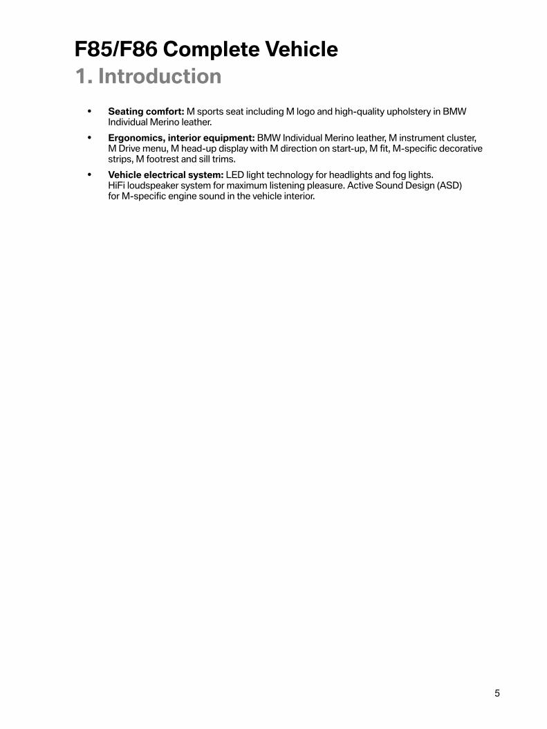
Engine�cooling�with�exhaust�turbocharger
The�engine�cooling�system�is�an�independent�coolant�circuit,�the�so-called�“high-temperaturecircuit”.�It�comprises�the�conventional�engine�cooling�and�cooling�of�the�turbochargers.�Even�thevehicle�interior�heating�is�supplied�by�the�coolant�circuit�of�the�engine�cooling�system.
F85/F86�engine�cooling�with�turbocharger,�schematic
Index Explanation2 Radiator,�engine3 Coolant�temperature�sensor�at�radiator�outlet4 Electric�fan8 Thermostat9 Mechanical�coolant�pump

F85/F86�Complete�Vehicle4.�Engine/Powertrain
31
Index Explanation10 Exhaust�turbocharger11 Heat�exchanger12 Heating�system�heat�exchanger�control�valve13 Electric�coolant�pump,�exhaust�turbocharger14 Electric�coolant�pump,�heating,�vehicle�interior15 Coolant�temperature�sensor17 Coolant�expansion�tank,�engine19 Auxiliary�radiator,�engine
The�conventional�coolant�pump�is�driven�via�a�belt�and�cannot�be�used�for�cooling�the�exhaustturbocharger�after�the�engine�has�shut�down.�For�this�reason�there�is�an�electric�coolant�pump,�whichworks�at�a�power�of�20 W,�for�this�separate�coolant�circuit.�But�also�during�engine�operation�theelectric�coolant�pump�is�switched�on�taking�into�account�the�following�factors:
• Coolant�temperature�at�the�engine�outlet• Engine�oil�temperature• Injected�fuel�quantity
Using�these�values�the�heat�input�into�the�engine�is�calculated.�The�after-run�of�the�electric�coolantpump�can�last�up�to�30�minutes.�To�improve�the�cooling�effect,�the�electric�fan�is�activated�and�can�rundown�for�up�to�a�max.�of�11�minutes.
F85/F86�engine�cooling�with�turbocharger,�components

F85/F86�Complete�Vehicle4.�Engine/Powertrain
32
Index Explanation1 Heat�exchanger2 Coolant�expansion�tank,�engine3 Exhaust�turbocharger4 Coolant�temperature�sensor5 Electric�coolant�pump,�exhaust�turbocharger6 Coolant�temperature�sensor�at�radiator�outlet7 Radiator,�engine8 Thermostat9 Mechanical�coolant�pump10 Auxiliary�radiator,�engine11 Heating�system�heat�exchanger�control�valve

F85/F86�Complete�Vehicle4.�Engine/Powertrain
33
Charge�air�cooling
The�system�again�makes�use�of�so-called�“indirect”�charge�air�cooling,�which�is�cooled�by�a�separatecoolant�circuit,�the�so-called�“low-temperature�circuit”.
To�guarantee�sufficient�cooling�of�the�charge�air,�in�the�S63B44T2�engine�the�low-temperaturecoolant-to-air�heat�exchangers�are�adapted�when�compared�with�the�S63B44T0�engine.�Becausea�larger�surface�area�is�available�to�the�F85/F86�for�the�radiators�at�the�front�of�the�vehicle,�twolow�temperature�charge�air�coolers�are�used.�One�low-temperature�charge�air�cooler�is�locateddirectly�after�the�front�of�the�vehicle�as�the�first�component�of�the�radiator�assembly.�A�second�low-temperature�charge�air�cooler�is�located�upstream�of�the�radiator�assembly.�These�are�supplied�withcoolant�via�an�independent�cooling�system�with�two�electric�coolant�pumps.
F85/F86�charge�air�cooling,�schematic

F85/F86�Complete�Vehicle4.�Engine/Powertrain
34
Index Explanation1 Upstream�low-temperature�cooler,�charge�air5 Coolant�expansion�tank,�low-temperature�circuit,�charge�air6 Electric�coolant�pump,�low-temperature�circuit,�charge�air7 Indirect�charge�air�cooler,�bank�116 Indirect�charge�air�cooler,�bank�218 Electric�coolant�pump,�low-temperature�circuit,�charge�air20 Low-temperature�cooler,�charge�air
F85/F85�charge�air�cooling,�components
Index Explanation1 Coolant�expansion�tank,�charge�air2 Indirect�charge�air�cooler,�bank�23 Electric�coolant�pump,�low-temperature�circuit,�charge�air4 Low-temperature�coolant�radiator,�charge�air5 Upstream�low-temperature�coolant�radiator,�charge�air6 Electric�coolant�pump,�low-temperature�circuit,�charge�air7 Indirect�charge�air�cooler,�bank�1

F85/F86�Complete�Vehicle4.�Engine/Powertrain
35
The�S63B44T2�engine�again�uses�two�electric�auxiliary�coolant�pumps,�as�on�the�S63B44T0�engine,for�the�charge�air�cooling�low-temperature�circuit.�But�unlike�on�the�S63B44T0�engine,�which�had�foreach�cylinder�bank�an�additional�auxiliary�low-temperature�charge�air�coolant�radiator�and�thus�also�anadditional�electric�coolant�pump�for�the�charge�air�low-temperature�circuit�in�each�case,�the�S63B44T2engine�utilizes�a�pump�for�the�feed�and�a�pump�for�the�return.�The�indirect�charge�air�coolers�areconnected�in�series�to�the�respective�circuit.
Both�50 W�pumps�have�self-diagnosis�and�dry-running�protection,�which�can�lead�to�fault�code�entriesin�the�DME.�If�the�engine�speed�is�increased�by�15�minutes�over�a�period,�the�auxiliary�water�pumps�areswitched�off�and�a�fault�code�is�stored�in�the�DME.�The�expansion�tank�does�not�have�a�coolant�levelswitch�and�does�not�automatically�detect�when�the�fluid�level�is�too�low.
If�the�electric�coolant�pump�is�removed�and�then�to�be�reused,�it�is�important�to�ensure�that�it�is�setdown�still�filled�with�coolant.�Drying�out�may�cause�the�bearings�to�stick.�The�upshot�of�this�is�that�theelectric�coolant�pump�may�possibly�not�start,�which�in�turn�may�result�in�engine�damage.
Before�installing,�turn�the�pump�impeller�manually�to�ensure�that�it�moves�freely.

F85/F86�Complete�Vehicle4.�Engine/Powertrain
36
Charge�air�cooler
The�charge�air�coolers�have,�in�contrast�to�the�S63B44T0�engine,�been�adapted�to�the�installationspace�of�the�F85/F86.�The�charge�air�coolers�have�been�reduced�in�size�(dimensions),�but�still�deliverthe�same�performance�data�as�those�of�the�S63B44T0�engine.
• Charge�air�cooler�temperature�input:�approx.�160°�C�/�320°�F• Charge�air�cooler�temperature�output:�approx.�<�50°�C�/�122°�F• Charging�pressure:�2.5 bar• Pressure�loss�through�charge�air�cooler:�<�50�mbar
This�has�been�made�possible�with�optimized�charge�air�and�coolant�routing,�which�positivelyinfluences�the�pressure�loss�and�the�charge�air�cooling�in�the�charge�air�cooler.�The�charge�air�coolershave�been�altered�in�terms�of�their�geometry�in�such�a�way�that�they�can�be�directly�connected�at�thetop�to�the�turbocharger�compressor�wheel.�The�connections�have�been�optimized�downwards�in�sucha�way�as�to�facilitate�a�direct�connection�to�the�electronic�throttle�valves�via�a�connection�hose.�Thishas�made�it�possible�to�adopt�the�intake�neck�with�the�electronic�throttle�valves�from�the�N63B44O1engine.�The�system�supplier�of�the�new�charge�air�coolers�is�Delphi.
F85/F86�charge�air�coolers,�comparison
Index ExplanationA Charge�air�cooler�S63B44T0B Charge�air�cooler�S63B44T2
Cooling�power�limits
If�under�extreme�conditions�such�as�for�example�in�countries�with�high�outside�temperatures�andthe�cooling�power�reaches�its�limits�on�the�racetrack�under�race�conditions,�the�cooling�power�of�thevehicle�air�conditioning�is�reduced�as�the�very�first�measure.�Reducing�the�cooling�power�for�the�airconditioning�ensures�that�there�is�sufficient�cooling�power�available�for�the�engine�cooling�and�chargeair�cooling.�The�driver�is�alerted�by�a�Check�Control�message�if�the�cooling�power�of�the�engine�coolingor�charge�air�cooling�reaches�its�limits.�In�the�event�of�a�customer�complaint�relating�to�the�coolingpower�of�the�vehicle's�air�conditioning�system,�it�is�essential�first�to�take�these�boundary�conditionsinto�consideration�before�starting�troubleshooting�on�the�cooling�system�and�on�the�air�conditioning.

F85/F86�Complete�Vehicle4.�Engine/Powertrain
37
4.1.12.�Engine�electrical�systemThe�MEVD�17.2.H�from�Bosch�is�used�as�the�engine�control�unit�in�the�S63B44T2�engine.�The�MEVD17.2.H�is�closely�related�to�the�MEVD�17.2.8�as�used�in�the�N63B44O1.�However�the�MEVD�17.2.Hsupports�the�software�function�“Controlled�Valve�Operation”�(CVO)�and�also�facilitates�the�use�of�theelectrical�exhaust�flap�actuator�(EAKS).
The�F85/F86�use�a�MEVD�17.2.H�engine�control�unit�for�each�cylinder�bank.
The�two�engine�control�units�are�identically�housed�in�the�F85/F86�in�terms�of�installation�position,but�are�not�water-cooled�as�in�the�F15/F16�with�the�MEVD�17.2.8.

F85/F86�Complete�Vehicle4.�Engine/Powertrain
38
DME�1�Main
F85/F86�MEVD�17.2.H�Main

F85/F86�Complete�Vehicle4.�Engine/Powertrain
39
Index Explanation1 Engine�electronics�Valvetronic�direct�fuel�injection�MEVD�17.2.H�DME�12 Ambient�pressure�sensor3 Temperature�sensor4 FlexRay5 PT-CAN6 PT‐CAN27 Secondary�DME�28 Tank�leak�diagnosis,�Natural�Vacuum�Leak�Detection�NVLD�(only�US�version)9 Car�Access�System�(CAS)10 Relay,�terminal�15N11 Relay,�terminal�3012 Relay,�terminal�3013 Electric�fan14 Relay�for�electric�fan15 Data-map�thermostat16 Electropneumatic�pressure�converter�(EPDW)�wastegate�117 Tank�vent�valve�118 VANOS�solenoid�valve,�intake�camshaft,�bank�119 VANOS�solenoid�valve,�exhaust�camshaft,�bank�120 Electric�coolant�pump,�exhaust�turbocharger21 Electrical�exhaust�flap�actuator�122 Quantity�control�valve,�bank�123–26 Injectors�1–427–30 Ignition�coils�1–431 Ground32 Oxygen�sensor�LSF�4.2,�bank�133 Oxygen�sensor�LSU�ADV,�bank�134 Diagnostic�connector35 Charging�pressure�sensor�before�throttle�valve,�bank�136 Rail�pressure�sensor,�bank�137 Charge�air�temperature�and�intake�pipe�pressure�sensor
after�throttle�valve,�bank�138 Knock�sensor�1–239 Knock�sensor�3–440 Hot�film�air�mass�meter�HFM�7,�bank�1

F85/F86�Complete�Vehicle4.�Engine/Powertrain
40
Index Explanation41 Camshaft�sensor,�intake�camshaft,�bank�142 Camshaft�sensor,�exhaust�camshaft,�bank�143 Crankshaft�sensor,�signal�is�looped�through�to�DME�slave44 Accelerator�pedal�module45 Throttle�valve,�bank�146 Engine�temperature�(sensor�at�housing�of�coolant�pump)47 Coolant�temperature�at�radiator�outlet48 Oil�temperature�sensor49 Oil�pressure�switch50 Engine�dynamics�button51 Valvetronic�servomotor,�bank�152 Oil�level�sensor53 Intelligent�battery�sensor�IBS54 Electric�coolant�pump,�charge�air�cooler�155 DC/DC�converter�(for�automatic�engine�start-stop�function)56 Alternator
Engine�dynamics�control�can�be�configured�by�the�driver�via�the�M�Drive�menu�in�the�iDrive�or�thekeypad�in�the�center�console.

F85/F86�Complete�Vehicle4.�Engine/Powertrain
41
DME�2�Secondary
F85/F86�MEVD�17.2.H�Secondary

F85/F86�Complete�Vehicle4.�Engine/Powertrain
42
Index Explanation1 Engine�electronics�Valvetronic�direct�fuel�injection�MEVD�17.2.H�DME�22 Ambient�pressure�sensor3 Temperature�sensor4 FlexRay5 PT-CAN6 PT‐CAN27 Primary�DME�18 DME1/�DME2�encoding9 Car�Access�System�(CAS)10 Terminal�15N11 Terminal�30B12 Supply�with�DME�113 Tank�vent�valve�214 VANOS�solenoid�valve,�intake�camshaft,�bank�215 VANOS�solenoid�valve,�exhaust�camshaft,�bank�216 Electropneumatic�pressure�converter�(EPDW)�wastegate�217 Electrical�exhaust�flap�actuator�218 Quantity�control�valve,�bank�219–22 Injectors�5–823–26 Ignition�coils�5–827 Ground28 Oxygen�sensor�LSF�4.2,�bank�229 Oxygen�sensor�LSU�ADV,�bank�230 Charging�pressure�sensor�before�throttle�valve,�bank�231 Rail�pressure�sensor,�bank�232 Charge�air�temperature�and�intake�pipe�pressure�sensor
after�throttle�valve,�bank�233 Knock�sensor�5–634 Knock�sensor�7–835 Hot�film�air�mass�meter�HFM�7,�bank�236 Camshaft�sensor,�intake�camshaft,�bank�237 Camshaft�sensor,�exhaust�camshaft,�bank�238 Fuel�low-pressure�sensor

F85/F86�Complete�Vehicle4.�Engine/Powertrain
43
Index Explanation39 Throttle�valve,�bank�240 M�Servotronic�button41 Valvetronic�servomotor,�bank�242 Electric�coolant�pump,�charge�air�cooler�2
M�Servotronic�can�be�configured�by�the�driver�via�the�M�Drive�menu�in�the�iDrive�or�the�keypad�in�thecenter�console.
4.1.13.�Service�information
Engine�oil�filling
Similarly�to�other�BMW�M�vehicles�with�S�engines,�an�engine�oil�change�is�scheduled�at�2000 km�/1200�miles�(pre-delivery�check)�on�the�F85/F86�with�the�S63B44T2�engine.
4.2.�Power�transmission
F85/F86�powertrain

F85/F86�Complete�Vehicle4.�Engine/Powertrain
44
4.2.1.�M�automatic�transmissionThe�F85/F86�uses�a�M�automatic�transmission�with�Drivelogic�with�the�designation�GM8HP75Z.It�is�called�M8HP75�in�the�following.
With�the�M�Sport�automatic�transmission�M8HP75,�which�is�based�on�the�8HPTU�of�BMW�AG,�thecustomer�is�able�to�enjoy�significantly�more�spontaneous�gearshifts�and�further�optimized�control�ofthe�converter�lockup�clutch.
This�has�been�made�possible�by�the�further�development�of�converter�technology�to�effectively�damprotational�irregularities�in�the�drivetrain�with�a�turbine�torsional�vibration�damper.�In�this�way�it�hasbeen�possible�to�reduce�even�further�the�operating�ranges�in�which�the�converter�lockup�clutch�has�tobe�controlled�with�the�result�that�the�converter�lockup�clutch�is�closed�in�the�vast�majority�of�drivingsituations.�This�provides�for�an�even�more�direct�connection�of�the�M8HP75�transmission�to�thecomplete�drivetrain,�resulting�in�an�even�sportier�driving�experience�and�reduced�fuel�consumption.
The�power�transmission�capability�of�the�torque�converter�has�been�adapted�to�the�increased�torqueof�the�S63B44T2�engine.
In�the�F85/F86�the�“Idle�coasting”�feature�known�from�the�non�Motorsport�vehicles�is�not�used.However,�the�M8HP75�supports,�the�“ConnectedShift”�function�which�is�used�in�the�BMW�AGvehicles.
Transmission�ratios,�comparison�E70�M/E71�M-F85/F86
E70�M�/�E71�M F85/F86Transmission�designation 6HP26S M8HP75Spread 6.0 7.8Maximum�engine�speed�[rpm] 6800 7200Torque�[Nm] 680 760Ratio�[:1]�1st�gear 4.171 5.000Ratio�[:1]�2nd�gear 2.340 3.200Ratio�[:1]�3rd�gear 1.521 2.143Ratio�[:1]�4th�gear 1.143 1.720Ratio�[:1]�5th�gear 0.867 1.313Ratio�[:1]�6th�gear 0.691 1.000Ratio�[:1]�7th�gear 0.823Ratio�[:1]�8th�gear 0.640Ratio�[:1]�reverse�gear 3.403 3.478
F85/F86�Complete�Vehicle4.�Engine/Powertrain
45
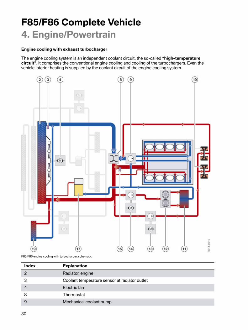
Transmission�oil�cooling
The�plastic�transmission�oil�sump�has�been�replaced�by�an�aluminium�version�with�larger�cooling�finsand�the�opening�point�of�the�transmission�oil�thermostats�has�been�lowered,�improving�the�cooling�ofthe�M8HP75�transmission.
An�additional�transmission�oil�cooler�with�thermostat�is�used�as�well�as�the�standard�oil-to-water�heatexchanger�with�thermostat�to�cool�the�M8HP75�in�F85/F86.�This�additional�transmission�oil�cooler,which�is�designed�as�a�plate�heat�exchanger,�operates�according�to�the�oil-to-air�heat�exchangerprinciple�and�is�installed�horizontally�in�front�of�the�radiator�assembly.
F85/F86�transmission�oil�cooling
Index Explanation1 Additional�transmission�oil�cooler�(oil-to-air�heat�exchanger�principle)2 Thermostat3 Transmission�oil�cooler�(oil-to-water�heat�exchanger)4 M�automatic�transmission5 Thermostat
The�cross-sections�of�the�outer�lines�and�hoses�carrying�transmission�oil�to�the�additionaltransmission�oil�cooler�(oil-to-air�heat�exchanger�principle)�and�transmission�oil�cooler�have�beenoptimized.�This�results�in�a�greater�oil�flow�rate,�translating�into�more�efficient�cooling�of�theM�automatic�transmission.
The�thermostat�of�the�transmission�oil�cooler�(oil-to-water�heat�exchanger)�opens�at�86° C�/186°�Fand�that�of�the�additional�transmission�oil�cooler�(oil-to-air�heat�exchanger�principle)�at�92° C�/�197°�F.Both�transmission�oil�coolers�are�fully�open�at�104° C�/�219°�F.

F85/F86�Complete�Vehicle4.�Engine/Powertrain
46
Gear�selector�lever
The�M�automatic�transmission�is�operated�using�the�M�gear�selector�lever�(M�GWS)�or�the�gearshiftpaddles�on�the�steering�wheel.
The�BMW�X5�M�and�BMW�X6�M�does�not�use�a�gear�selector�lever�as�seen�in�a�BMW�automatictransmission;�instead,�it�uses�the�gear�selector�lever�of�the�M�double-clutch�transmission�as�seen�inBMW�M�vehicles.�This�means�that�the�M�gear�selector�levers�have�a�uniform�appearance,�regardlessof�whether�the�BMW�M�vehicle�in�question�is�equipped�with�an�M�double-clutch�transmission�or�an�Mautomatic�transmission.
M�GWS/M�gear�selector�lever
A�button�for�engaging�the�parking�lock�as�featured�on�the�gear�selector�lever�of�the�automatictransmission�is�omitted.�The�parking�lock�is�automatically�engaged�as�in�the�M�double-clutchtransmission.�The�transmission�stage�“Park�P”�is�selected�as�in�the�logic�familiar�from�Mdouble-clutch�transmissions.
It�is�possible�to�choose�and�change�between�an�automatic�“D�mode”�and�a�sequential�“S�mode”.In�each�mode�there�are�three�driving�programs,�which�can�be�selected�and�activated�with�the“Drivelogic�switch”.

F85/F86�Complete�Vehicle4.�Engine/Powertrain
47
Drivelogic
The�number�of�driving�programs�is�the�same�as�in�F1x�M,�F80,�F82,�F83�and�F06�M6�vehicles.The�haptics�of�the�Drivelogic�switch�have�been�altered,�as�already�seen�in�the�F80,�F82,�F83.�A�rockerwas�installed�for�the�E9x�M3�and�for�F1x�M�vehicles,�while�in�the�new�F85/F86�a�normal�pressureswitch�is�used�for�clicking�through.
After�each�change�between�Sequential�mode�and�Drive�mode�the�last�selected�drivingprogram�is�active.
After�each�engine�start�driving�program�1�is�active�in�Drive�mode.
D�mode/Drive�mode
Automated�mode,�all�the�forward�gears�are�automatically�shifted.�Kickdown�is�triggered�by�depressingthe�accelerator�pedal�beyond�the�pressure�point.
Three�driving�programs�are�available�for�selection:
1:�Efficient�drive
2:�Relaxed�drive
3:�Sporty�drive
S�mode/Sequential�mode
The�gears�can�be�manually�shifted�by�means�of�gearshift�paddles�on�the�steering�wheel�“+�or�–”�or�thegear�selector�lever�“forward�and�back”�at�the�matching�driving�speed�and�engine�revs.�The�selectedgear�is�maintained�even�when�the�engine�speed�limitation�is�reached,�but�an�automatic�downshift�isperformed�when�the�vehicle�drops�below�the�gear-specific�minimum�driving�speed.
When�the�S�mode�is�selected�for�the�first�time�after�terminal�change�(engine�restart),�the�last�Drivelogicstage�used�is�active.
Three�driving�programs�are�also�available�here�for�selection:
1:�Comfortable,�smooth�gearshifts�in�all�driving�conditions.
2:�Sporty,�fast�gearshifts,�light�gearshift�jolts�permitted�at�higher�load�and�engine�revs.
3:�Maximum�sporty�shift�speed�and�gearshifts�are�the�requirement�for�the�activation�of�Launch�Control.
To�use�the�highest,�i.e.�the�third�driving�program,�the�DSC�does�not�have�to�be�activated.
M�automatic�transmission�behavior�when�creeping
The�“Creep�on�request”�function�familiar�from�M�double-clutch�transmissions�is�effected�for�the�firsttime�in�conjunction�with�a�torque�converter�transmission.
• When�the�service�brake�or�parking�brake�is�released�with�a�drive�position�selected,there�is�no�“Creeping”�in�the�M�automatic�transmission�(rolling�possible).
• “Creep�on�request”�can�be�triggered�by�briefly�depressing�the�accelerator�pedal.This�request�is�cancelled�again�only�after�the�vehicle�has�come�to�a�standstill�again.
• The�Automatic�Hold�functions�are�maintained�as�on�the�F15/F16.

F85/F86�Complete�Vehicle4.�Engine/Powertrain
48
Launch�Control
Function:�Launch�Control�enables�optimal�acceleration�when�driving�off�on�a�dry�roadway.
Sequence Precondition/Action1. The�vehicle�must�be�stationary,�the�engine�running�and�at�operating
temperature�(approx.�10 km�/�6�mile�warm-up�journey).2. Dynamic�Stability�Control�is�deactivated�or�M�Dynamic�Mode�is�activated.3. The�Sequential�mode�and�the�third�Drivelogic�driving�program�are�selected.4. The�brake�pedal�is�gently�pressed�with�the�left�foot�and�held.5. The�accelerator�pedal�is�depressed�fully�and�held�in�this�position.6. In�the�M�instrument�cluster�a�flag�symbol�must�appear�(if�not,�check�notes�and
steps�1-5).7. An�optimum�engine�speed�for�pulling�away�is�adjusted.8. The�left�foot�is�taken�off�the�brake�within�5�seconds.
F85/F86�Launch�Control�active
Effect
• Launch�Control�automatically�shifts�up�using�the�shortest�possible�gearshift�times�andperformance-optimized�shift�points�as�long�as�the�driver�keeps�the�accelerator�pedal�fullydepressed.
• The�start�flag�in�the�instrument�cluster�remains�active.
A�renewed�Launch�Control�start�is�possible�as�long�as�the�transmission�oil�temperature�satisfies�thepreconditions�for�this.
Automatic�deactivation
• The�driver�leaves�(even�if�only�briefly)�the�accelerator�pedal�full-load�range�during�acceleration.
A�manual�intervention�in�the�automatic�upshift,�for�example�via�the�gearshift�paddles�on�the�steeringwheel�or�the�gear�selector�lever,�does�not�interrupt�the�Launch�Control�process.

F85/F86�Complete�Vehicle4.�Engine/Powertrain
49
If�one�of�these�preheating/precooling�conditions�is�breached,�it�is�not�possible�to�activate�the�LaunchControl.
Also�at�excessive�transmission�oil�temperature�(e.g.�repeat�Launch�Control�or�race-like�start),activation�is�blocked�up�until�an�acceptable�temperature�threshold�is�reached.
The�start�flag�goes�out�with�every�deactivation�and�the�automatic�forced�upshift�is�cancelled.
Premature�wear�occurs�as�a�result�of�the�high�load�of�the�vehicle�with�use�of�the�launch�control.
A�mechanical�emergency�transmission�release�is�available�and�can�only�be�accessed�under�thevehicle.�An�electronic�emergency�transmission�release�is�also�implemented�as�in�automatictransmissions�of�non�Motorsport�vehicles.�For�towing�instructions,�please�observe�the�informationin�the�Owner's�Handbook�of�the�vehicle.
4.2.2.�Axle�drive�and�transfer�box
Front�axle�differential
The�front�axle�differential�VAG178AL�known�from�the�F15/F16�is�used.
For�further�information�on�the�front�axle�differential,�please�refer�to�the�Technical�Training�Manual�“F15Complete�Vehicle”.
Transfer�box
The�ATC45L�as�known�from�the�F15/F16�is�used�as�the�transfer�box.�Design�measures�for�increasingrigidity�and�strength�have�been�incorporated�into�the�ATC45L�in�order�to�satisfy�the�higher�torquerequirement�in�the�F85/F86.�The�output�flange�on�the�transfer�box�has�been�adapted�to�the�alteredflange�dimensions�of�the�drive�shaft.
For�further�information�on�the�transfer�box,�please�refer�to�the�Technical�Training�Manual�on�the�F15Complete�Vehicle�and�F25�LCI/F26�Complete�Vehicle.

F85/F86�Complete�Vehicle4.�Engine/Powertrain
50
Rear�axle�differential�(final�drive�unit)
The�HAG�225�QMV�rear�axle�differential�in�conjunction�with�Dynamic�Performance�Control,�also�usedas�optional�equipment�in�the�F15/F16,�are�used�in�the�F85/F86.
The�gear�ratio�of�the�HAG�225�QMVH�is�3.15.
F85/F86�Dynamic�Performance�Control�(QMVH)
Index Explanation1 Dynamic�Performance�Control,�rear�axle�differential�(QMVH)2 Air�guide
An�air�guide�for�increasing�cooling�power�is�mounted�on�the�QMVH�rear�axle�housing.
The�output�flanges�of�the�rear�axle�differential�have�been�adapted�to�the�dimensions�of�the�outputshaft�flexible�joints.
For�further�information�on�the�rear�axle�differential,�please�refer�to�the�Technical�Training�Manual�“F15Complete�Vehicle”.

F85/F86�Complete�Vehicle4.�Engine/Powertrain
51
4.2.3.�Flexible�disc,�Drive�shaft�and�output�shafts
Flexible�disc
The�flexible�disc�has�been�adapted�to�the�increased�power�level�for�the�F85/F86.�The�flexible�disc�is,�incontrast�to�the�F15/F16,�14 mm�wider�and�now�measures�44 mm�in�width.�The�flexible�disc�in�the�F85/F86�has�increased�in�diameter�to�110 mm,�likewise�corresponding�to�14 mm�in�comparison�with�theF15/F16.
Drive�shaft
The�drive�shaft�of�the�F85/F86�is�a�steel�shaft,�the�heaviest�and�most�stable�drive�shaft�that�has�everbeen�used�on�a�BMW�or�BMW�M�vehicle.�The�drive�shaft,�the�center�mount,�the�flange�on�the�flexibledisc�to�the�transfer�box�and�the�flange�on�the�rear�axle�differential�have�been�adapted�in�terms�ofdesign�and�strength�to�the�enormous�power�of�the�F85/F86.�The�flexible�disc�to�the�transfer�box�and�tothe�rear�axle�differential�is�a�common�part�in�terms�of�design.
The�bolt�connections�of�the�drive�shaft�to�the�transfer�box�through�the�flexible�disc�have�been�adaptedin�terms�of�their�larger-diameter�to�accommodate�the�larger-dimensioned�flexible�disc.
Drive�shaft,�front
The�drive�shaft�(front)�is�a�common�part�for�the�F15/F16�and�therefore�corresponds�in�its�dimensionsand�design�to�the�drive�shaft�(front)�known�from�the�F15�and�F16.
Output�shafts,�rear
The�flexible�joints�of�the�output�shafts�have�been�adapted�in�terms�of�design�and�strength�to�the�higherpower�in�the�F85/F86.
Drive�flanges,�rear
The�drive�flanges�(rear)�have�been�adapted�to�the�F85/F86�and�have�additional�retaining�pins�foraccommodating�the�M�compound�brake�discs.
Output�shaft,�front
The�output�shafts�(front)�are�a�common�part�of�the�output�shafts�known�from�the�F15�and�F16.
Wheel�bearings,�front
The�wheel�bearings�(front)�have�been�adapted�to�the�F85/F86�and�have�additional�retaining�pins�foraccommodating�the�M�compound�brake�discs.

F85/F86�Complete�Vehicle4.�Engine/Powertrain
52
4.2.4.�Service�information
Transmission�oil�circuit
For�work�required�on�the�oil�circuit�of�the�automatic�transmission,�for�example�after�an�accident,�or�ifthe�oil�circuit�has�to�be�opened�due�to�a�repair,�there�must�be�maximum�cleanliness.�This�includes:
• Optimal�cleaning�of�the�outer�oil�circuit�areas�before�disassembly�of�the�components�oropening�the�oil�circuit.
• Immediate�closure�of�openings�and�lines�after�disassembly�without�delay�and�using�cleanoriginal�plugs.�Do�not�use�unsealed�components�or�replacement�parts�of�the�oil�circuit�withoutchecking�for�cleanliness�and�where�possible�competent�repair.
• The�workbay�in�which�an�automatic�transmission�is�opened�must�be�extremely�clean�andsecured�against�dirt�contamination,�also�during�work�interruptions.�For�example�by�sufficientlyclean�and�lint-free�cover.
Lifetime�oil�filling
Currently,�as�with�the�E7x�M�with�automatic�transmission,�for�the�F85/F86�with�M�automatictransmission�a�transmission�oil�change�is�not�required�at�2000�km�/�1200�miles�(pre-delivery�check)�orwith�every�third�engine�oil�change.
Rear�axle�differential�(final�drive�unit)
Both�F85/F86�vehicles�are�equipped�with�Dynamic�Performance�Control�as�standard�equipment.�Arear�axle�differential�oil�change�is�required�at�2000�km�/�1200�miles�(running�in�check)�and�at�every�fifthengine�oil�change�(at�approximately�each�50,000�miles).�Note:�There�are�three�drain�plugs�on�the�reardifferential.�However�only�the�oil�in�the�center�section�of�the�QMVH�needs�to�be�changed�as�the�twoouter�sections�of�the�differential�are�filled�with�long-term�rated�oil.
During�the�oil�change,�after�allowing�the�oil�to�fully�drip�out�of�the�center�section,�fill�with�SAF-XO�oil(ETK�#�33�11�7�695�240)�and�pour�0.95�liters�(exactly�1.0�qt).�DO�NOT�FILL�TO�THE�LOWER�EDGEOF�THE�FILLING�HOLE�

F85/F86�Complete�Vehicle5.�Chassis/Driving�Dynamics�Systems
53
F85/F86�chassis�and�suspension
5.1.�Axles
5.1.1.�Front�axleThe�double-wishbone�front�axle�known�from�the�F15/F16�is�used�as�the�front�axle.�The�front�axle�hasbeen�lowered�by�10 mm�in�comparison�with�the�standard�suspension�on�the�F85/F86.�The�upperA-arm�has�been�adapted�by�a�repair�wishbone�from�the�F15/F16�spare�parts�range�in�order�to�achievethe�M-specific�greater�camber�values�for�a�sportier�suspension�setting.�The�rubber�mounts�forconnecting�to�the�front�axle�support�of�the�lower�wishbone�and�the�tension�strut�have�been�matchedfor�the�F85/F86.�The�spring�strut�has�been�adapted�by�a�separate�damper�variant�together�with�the�coilspring�to�the�F85/F86�and�bolted�at�the�top�by�a�newly�dimensioned�support�bearing�in�the�dome;�inaddition,�the�auxiliary�damper,�installed�between�the�shock�absorber�and�the�support�bearing�on�thepiston�rod,�has�been�adapted.�For�further�information�on�the�double-wishbone�front�axle,�please�referto�the�Technical�Training�Manual�“F15�Complete�Vehicle”.
5.1.2.�SteeringWithin�the�framework�of�the�EfficientDynamics�measures�for�the�F85/F86,�the�steering�used�is�arack-and-pinion�steering�with�electrical�steering�wheel�support�“M�Servotronic�based�on�an�EPS”.

F85/F86�Complete�Vehicle5.�Chassis/Driving�Dynamics�Systems
54
For�power�assistance�during�steering�an�electric�motor�is�housed�parallel�to�the�rack�at�the�steeringgear�housing,�the�power�transmission�is�effected�via�a�ball�screw.
As�components�of�M�Servotronic�(EPS)�the�ratio�of�the�rack�has�been�specifically�adapted�for�the�F85/F86.�With�this�measure�the�development�of�the�steering�was�able�to�be�coordinated�to�the�typical�Mproperties.�Special�attention�was�paid�here�to�the�typical�M�features:
• Direct�steering�sensation• Driving�condition�feedback• Dynamic�driving�in�the�limit�range
The�ratio�of�M�Servotronic�(EPS)�has�been�adapted�to�the�F85/F86;�of�particular�note�is�the�fact�afteran�eighth�of�a�turn�of�the�steering�wheel�the�rack�ratio�increases�by�8�%.
F85/F86�Comparison�of�steering�gear�ratio,�M�Servotronic�(EPS)�steering
Index Explanation1 Rack,�basic�version�F15/F16�(constant�gear�geometry)2 Rack,�variable�sport�steering�F85/F86�(variable�gear�geometry)A More�indirect�steering�gear�ratio�(variable�sport�steering)B More�direct�steering�gear�ratio�(variable�sport�steering)X Steering�wheel�angley Rack�travel

F85/F86�Complete�Vehicle5.�Chassis/Driving�Dynamics�Systems
55
With�the�use�of�the�M�Servotronic�(EPS)�in�the�new�F85/F86�the�parking�assistance�system�“ParkingManoeuvring�Assistant”�(option�SA�5DP)�is�now�also�offered.
The�system�supplier�of�M�Servotronic�(EPS)�is�ThyssenKrupp.
M�Servotronic�(EPS)�can�be�configured�by�the�driver�via�the�M�Drive�menu�in�the�iDrive�or�the�keypadin�the�center�console.
For�further�information�on�EPS,�please�refer�to�the�Technical�Training�Manual�“F15�Complete�Vehicle”.
5.1.3.�Rear�axleThe�Integral�IV�rear�axle�known�from�the�F15/F16�is�used�as�the�rear�axle.�The�rear�axle�has�beenlowered�by�10 mm�in�comparison�with�the�standard�suspension�on�the�F85/F86.�The�rear�axle�supportof�the�F85/F86�is�however�supported�by�the�incorporation�of�Cellasto�discs�at�the�top�and�bottomof�the�bolting�points�of�the�rear�axle�bearings.�The�incorporation�of�Cellasto�discs�prevents�the�rearaxle�support�from�tilting�at�the�rear�axle�support�bearings�in�the�event�of�a�marked�load�reversal.�Therear�axle�support�bearings�have�been�adapted�in�terms�of�a�harder�design�to�the�F85/F86.�The�shockabsorbers�have�been�adapted�by�a�separate�damper�variant�to�the�F85/F86�and�are�bolted�at�the�topwith�a�newly�dimensioned�support�bearing;�in�addition,�the�auxiliary�damper,�installed�between�theshock�absorber�and�the�support�bearing�on�the�piston�rod,�has�been�adapted.�The�U-type�bellows�onthe�rear�axle�have�been�adapted�by�modified�roll�pistons�to�the�F85/F86.�For�further�information�on�theIntegral�IV�rear�axle,�please�refer�to�the�Technical�Training�Manual�“F15�Complete�Vehicle”.
5.2.�Brakes,�wheels�and�tires
5.2.1.�Brakes
M�compound�brake
Designation Unit E7x�M F85/F86Front�brake 4�pistons,�fixed�caliper 6�pistons,�fixed�caliperBrake�disc,�front [mm] 395�x�36 395�x�36Design,�brake�disc,front
Internally�ventilatedcast�brake�disc,unperforated
Internally�ventilatedM�compound�brakedisc,�perforated
Rear�brakes 1�piston,floating�caliper
1�piston,floating�caliper
Brake�disc,�rear [mm] 385�x�24 385�x�24Design,�brake�disc,rear
Internally�ventilatedcast�brake�disc,unperforated
Internally�ventilatedM�compound�brakedisc,�perforated
Parking�brake electro-mechanical
electro-mechanical

F85/F86�Complete�Vehicle5.�Chassis/Driving�Dynamics�Systems
56
The�front�brake�is�completely�F85/F86-specific.�It�is�a�large�perforated�and�ventilated�M�compoundbrake�disc�combined�with�a�four-piston�fixed�caliper.�The�use�of�the�six-piston�brake�caliper�hasincreased�the�friction�surface�of�the�individual�brake�pads�by�30 %�compared�with�the�E7x�M.This�measure�has�positively�influenced�the�braking�power�and�reduce�the�fading�properties�comparedwith�the�E7x�M.
Compared�with�the�E7x�M,�the�brake�disc�has�the�same�dimensions,�but�the�friction�ring�thicknessesand�cooling�ducts�of�the�brake�discs�have�been�M-specifically�optimized.
All�front�brake�calipers�are�blue�with�a�colored�M�logo.
F85/F86�front�brake
The�rear�perforated�and�ventilated�M�compound�brake�disc�has�the�same�dimensions�as�the�E7x�M.The�rear�brake�caliper�is�a�single-piston�fixed�caliper�and�has�been�adopted�from�the�production�F15/F16.
The�rear�brake�calipers�are�blue.
M�carbon�ceramic�brakes
M�carbon�ceramics�brakes�are�not�offered.

F85/F86�Complete�Vehicle5.�Chassis/Driving�Dynamics�Systems
57
5.2.2.�Wheels/tires
Summer�equipment
F85/F86�summer�wheels
Index ExplanationA 20"�611M�no�charge�wheel�optionB 21"�612M�standard�equipment�wheel
The�following�wheel/tire�combinations�are�offered:
Standard�equipment
Designation E7x�M F85/F86LM�EH2�wheel�rim�standard�wheel�front 10J�x�20�IS40
299M/300M10J�x�21�IS40Styling�612M
LM�EH2�wheel�rim�standard�wheel�rear 11J�x�20�IS35299M/300M
11.5J�x�21�IS38Styling�612M
Standard�tire�front 275/40�R20 285/35�R21Standard�tire�rear 315/35�R20 325/30�R21
No�charge�optional�equipment
Designation F85/F86LM�EH2�wheel�rim,�front�(forged)�styling�611M 10J�x�20�IS40LM�EH2�wheel�rim,�rear�(forged)�styling�611M 11.5J�x�20�IS38Tires,�front 285/40�R20Tires,�rear 325/35�R20

F85/F86�Complete�Vehicle5.�Chassis/Driving�Dynamics�Systems
58
Winter�equipment
Designation E7x�M F85/F86EH2�Wheel�rim�front/rear�axle�(cast)�front/rear
9J�x�19�IS37/9Jx�19�IS18
Styling�298M
10J�x�20�IS40/10Jx�20�IS32
Styling�611MTire 255/50�R19 285/40�R20�M+S
Tires:�Non-Runflat
Tires�without�run-flat�technology�are�used�on�the�F85/F86.�So-called�UHP�tires�(Ultra-High-Performance�tires)�without�run-flat�properties�are�used.�Tires�without�run-flat�properties�are�softer�inthe�sidewall�area�and�afford�the�handling�and�comfort�benefits�that�are�wanted�in�a�BMW�M�vehicle.
The�components�of�the�above-listed�wheel/tire�combinations�have�been�developed�specially�for�theF85/F86.�This�can�be�recognized�by�the�star�on�the�outer�side�of�the�tire,�among�other�things.
Other�combinations�may�have�a�negative�effect�on�the�performance�and�the�driveability�of�the�F85/F86.
5.3.�Driving�dynamics�systemsThe�F85/F86�is�equipped�as�standard�with�Vertical�Dynamics�Management�(VDM�and�Dynamic�Drive)and�Integrated�Chassis�Management�(Dynamic�Performance�Control�and�M�Servotronic).
Active�steering�is�not�offered�in�the�F85/F86.�Both�vehicles�have�a�M�Servotronic�system�based�onelectromechanical�power�steering�(EPS)�with�a�more�direct,�variable�steering�gear�ratio.
All�Vertical�Dynamics�Management�system�have�been�M-specifically�coordinated.
The�M-specific�coordination�of�the�driving�dynamics�(longitudinal,�transverse�and�vertical)�waseffected�on�the�Nürburgring�Nordschleife.�The�main�criteria�were�handling�and�the�lap�times.
5.3.1.�Vertical�Dynamics�Management
Dynamic�Drive
Active�Roll�Stabilization�(ARS�-�Dynamic�Drive),�as�known�from�the�F15/F16�basic�vehicles,�is�used�onthe�F85/F86.
The�anti-roll�bars�and�the�front�and�rear�axles�are�separated�and�can�be�connected�together�using�ahydraulic�swivel�motor.�Dynamic�Drive�can�very�quickly�generate�a�torque�at�the�anti-roll�bars�in�orderto�stabilize�the�vehicle.�For�straight-ahead�driving�the�two�halves�of�the�anti-roll�bars�are�disconnected.
The�settings�of�Active�Roll�Stabilization�(ARS)�are�coupled�to�VDM-EDC:
• VDM�Comfort�=�ARS�Comfort• VDM��Sport�=�ARS�Comfort• VDM�Sport+�=�ARS�Sport

F85/F86�Complete�Vehicle5.�Chassis/Driving�Dynamics�Systems
59
For�further�information�on�Dynamic�Drive,�please�refer�to�the�Technical�Training�Manual�“F15Complete�Vehicle”.
VDM
Vertical�Dynamics�Management�(VDM),�as�known�from�the�F15/F16�basic�vehicle,�is�used�on�the�F85/F86.
VDM�is�an�electronic�damper�control�system�(EDC)�for�controlling�vertical�dynamics.�The�VDM�controlunit�calculates�individual�control�commands�for�the�electromagnetic�valves�in�the�shock�absorber,based�on�the�information�input�about:
• the�body�and�wheel�acceleration• current�lateral�and�longitudinal�acceleration• driving�speed• and�the�steering�wheel�position.
Based�on�this�measured�data,�the�VDM�control�unit�calculates�the�control�commands�to�be�sent�tothe�electromagnetic�valves�in�the�shock�absorbers�for�each�individual�wheel�according�to�the�roadprofile�and�driving�situation.�This�means�that�the�damping�forces�will�always�be�applied�according�torequirements.
VDM�can�be�configured�by�the�driver�via�the�M�Drive�menu�in�the�iDrive�or�the�keypad�in�the�centerconsole.
For�further�information�on�VDM,�please�refer�to�the�Technical�Training�Manual�“F15�Complete�Vehicle”.
Electronic�ride�height�control�(EHC)
Electronic�ride�height�control�(EHC),�as�featured�in�the�F15/F16�basic�vehicles,�is�used�in�the�F85/F86.
In�order�to�be�able�to�maintain�the�ride�comfort,�the�ground�clearance�and�the�spring�travelindependent�of�the�vehicle�load�or�trailer�load,�a�self-levelling�suspension�can�be�used�on�the�rear�axle.
For�further�information�on�EHC,�please�refer�to�the�Technical�Training�Manual�“F15�Complete�Vehicle”.

F85/F86�Complete�Vehicle5.�Chassis/Driving�Dynamics�Systems
60
5.3.2.�Transverse�dynamics�management
Integrated�Chassis�Management�ICM
Integrated�Chassis�Management�(ICM)�is�the�transverse�dynamics�system�network.�This�control�unitcoordinates�the�interaction�between�M�Servotronic�(EPS),�DSC,�VDM,�engine�control�and�DynamicPerformance�Control.
Dynamic�Performance�Control�(QMVH)
Dynamic�Performance�Control�is�the�further�development�of�the�intelligent�four-wheel�drive�xDrive.To�date,�the�drive�torque�could�only�be�distributed�between�front�and�rear�axle.�Dynamic�PerformanceControl�now�also�allows�a�distribution�of�the�drive�torque�at�the�rear�axle.�The�familiar�rear�axledifferential�is�extended�with�two�variable�ratio�transmissions,�each�comprising�a�double�planetary�gearand�an�electric�multiple�disc�brake.�The�system�is�already�known�from�the�E71.
The�settings�of�Dynamic�Performance�Control�are�coupled�to�longitudinal�dynamics�management:
• DSC�On�=�QMVH�Comfort• DSC�MDM�=�QMVH�Sport• DSC�Off�=�QMVH�Sport
For�further�information�on�Dynamic�Performance�Control,�please�refer�to�the�Technical�Training�Manual“F15�Complete�Vehicle”�and�“E71�Complete�Vehicle”.
5.3.3.�Longitudinal�dynamics�managementLongitudinal�dynamics�management�is�performed�by�DSC.
DSC�9+�from�Bosch,�as�featured�in�the�F15/F16�production�vehicles,�is�used�in�the�F85/F86.
DSC�9+�has�been�M-specifically�coordinated�to�match�the�M�compound�brake�system.�Furthermore,DSC�9+�has�been�integrated�into�the�M�Dynamic�Mode�(MDM).�Further�adaptations�have�been�madeto�coordinate�DSC�9+�with�Dynamic�Performance�Control�and�the�M8HP�automatic�transmission.
In�M�Dynamic�Mode�(MDM)�the�control�threshold�of�the�brake�interventions�is�expanded/raised�and�theengine�power�reduction�by�ASC�is�applied�significantly�later.�This�enables�driver-oriented�dynamic�andsporty�driveability.
The�“DSC”�driving�dynamics�button�or�the�configuration�in�the�M�Drive�menu�is�used�to�switchbetween�DSC�ON,�MDM�and�DSC�OFF.�The�button�obtains�ground�from�ICM�and�sends�back�a�groundsignal�on�actuation�to�ICM.�ICM�forwards�this�information�on�the�FlexRay�data�bus�to�DSC.
Longitudinal�dynamics�can�be�configured�by�the�driver�via�the�M�Drive�menu�in�the�iDrive�or�the�keypadin�the�center�console.
For�further�information�on�longitudinal�dynamics�management,�please�refer�to�the�Technical�TrainingManual�“F15�Complete�Vehicle”.

F85/F86�Complete�Vehicle6.�Vehicle�Electr.�Syst/On-board�Info
61
6.1.�F85/F86�vehicle�electrical�system
F85/F86�bus�overview

F85/F86�Complete�Vehicle6.�Vehicle�Electr.�Syst/On-board�Info
62
Index Explanation1 Control�unit�with�wake-up�line2 Control�unit�authorised�to�perform�wake-up�function3 Start-up�node�control�units�for�starting�and�synchronizing
the�FlexRay�bus�systemACSM Advanced�Crash�Safety�Module�(ACSM)AHM Trailer�moduleAMPT Top�HiFi�amplifierASD Active�Sound�DesignCID Central�Information�DisplayCON ControllerD-CAN Diagnosis-on-Controller�Area�NetworkDME Digital�Motor�ElectronicsDME�2 Digital�Engine�Electronics�2DSC Dynamic�Stability�ControlEHC Electronic�ride�height�controlEKPS Electronic�fuel�pump�controlEMF Electromechanical�parking�brakeEthernet Cable-based�data�network�technology�for�local�data�networksFLA High-beam�assistantFKA Automatic�rear�air-conditioning�systemFlexRay Fast,�preset�and�fault-tolerant�bus�system�for�use�in�automotive�sectorFZD Roof�function�centerGZAR Right-hand�targeted�illumination�(not�US)GZAL Left-hand�targeted�illumination�(not�US)HEADUNIT Headunit�HighHKL Automatic�operation�of�tailgateHUD Head‐Up�DisplayICM Integrated�Chassis�ManagementIHKA Integrated�automatic�heating�/�air�conditioningK-CAN2 Body�controller�area�network�2K-CAN3 Body�Controller�Area�Network�3K-CAN4 Body�controller�area�network�4KAFAS Camera-based�driver�support�systemsKOMBI Instrument�cluster�(Media�Oriented�System�Transport�connection
not�in�basic�equipment)LHMR LED�main�light�module�on�the�right

F85/F86�Complete�Vehicle6.�Vehicle�Electr.�Syst/On-board�Info
63
Index ExplanationLHML LED�main�light�module�on�the�leftM�EGS M�electronic�transmission�controlM�EPS M�Servotronic�(EPS)M�GWS M�gear�selector�leverMOST Media�Oriented�System�Transport�busNVE Night�Vision�ElectronicsOBD On-board�diagnosisPCU Power�Control�UnitPDC Park�Distance�Control�(with�option�SA�5DP,�Parking�Manoeuvring�Assistant:
integrated�in�the�Parking�Manoeuvring�Assistant�control�unit,�otherwiseintegrated�in�the�Rear�Electronic�Module�[REM]�control�unit)
PMA Parking�manoeuvring�assistantPT-CAN Powertrain�controller�area�networkPT‐CAN�2CAN2 Powertrain�controller�area�network�2QMVH Rear�axle�lateral�torque�distributionREMAFA Reversible�electric-driven�reel,�leftREMABF Reversible�electric-driven�reel,�rightRFK Reversing�cameraRSE Rear�Seat�Entertainment�systemSMFA Seat�module,�driverSMBF Seat�module,�passengerSWW Lane�change�warningTBX TouchboxTCB Telematic�Communication�BoxTRSVC Top�rear�side�view�cameraVM Video�Module�(not�US)VTG Transfer�boxVDM Vertical�Dynamics�Management
The�following�deviations�exist�in�comparison�with�the�standard�F15/F16:
PT-CANThe�S63B44T2�engine�exclusively�has�the�DME�variant�MEVD17.2.H�in�a�master-slave�connection.In�place�of�the�electronic�transmission�control�(EGS)�the�M�automatic�transmission�with�Drivelogic(M�EGS)�is�used�and�instead�of�the�gear�selector�lever�(GWS)�the�M�gear�selector�lever�(M�GWS)�withDrivelogic�button�is�used.�The�SCR�control�unit�is�omitted.
FlexRayThe�electromechanical�power�steering�(EPS)�is�omitted,�with�M�Servotronic�(EPS)�being�used�instead.

F85/F86�Complete�Vehicle6.�Vehicle�Electr.�Syst/On-board�Info
64
K-CANThere�is�no�difference�from�the�current�F15/F16�vehicle�electrical�system.
MOSTThere�is�no�difference�from�the�current�F15/F16�vehicle�electrical�system.
6.2.�On-board�information
6.2.1.�M�instrument�clusterThe�M�instrument�cluster�of�the�F85/F86�is�based�on�the�instrument�cluster�from�the�F1x�M5/M6.The�respective�scales�of�the�instrument�cluster�are�market-�and�vehicle-specific.
The�following�M-specific�changes�exist�in�comparison�with�the�F15/F16:
Round�instruments:
• Speed�and�engine�speed�display�correspond�to�the�drive�concept(330 km/h�/�200�mph,�8000 rpm)
• Typical�M�red�needle,�lighting�of�the�dial�in�white�(also�during�the�daywithout�driving�light),�M�inscription.

F85/F86�Complete�Vehicle6.�Vehicle�Electr.�Syst/On-board�Info
65
M-specific�displays:
• MDM�M�dynamic�mode�symbol�in�place�of�the�DTC• M1�=�M�Drive1• M2�=�M�Drive2• Display�of�gear• Display�of�Drivelogic�(bar�symbol�such�as�a�button)• Display�of�system�status:�engine�dynamics,�damper�control�and�M�Servotronic.
In�the�instrument�cluster�the�current�configuration�of�the�engine�dynamics,�damper�control�and�MServotronic�systems�is�shown�in�the�bottom�part�of�the�rev�counter�field.�This�function�can�be�activatedunder�“Settings”�in�the�Configuration�menu�display.
F85/F85�M�Drive�menu
The�confirmation�of�the�M�Drive�settings�for�DSC�and�transmission�is�also�effected�centrally�in�theinstrument�cluster.
For�setting/adjustment�work�in�the�engine�dynamics,�EDC�and�M�Servotronic�systems�the�response�ofthe�button�activation�is�also�effected�as�a�list�in�the�instrument�cluster.

F85/F86�Complete�Vehicle6.�Vehicle�Electr.�Syst/On-board�Info
66
6.2.2.�M�Head‐Up�display�(option�SA�610)The�optional�color�head-up�display,�depending�on�the�national-market�version,�can�switch�to�theM-specific�display.
The�following�information/parameters�can�be�shown:
• Shift�point�indicator�by�Shift�light�function• Engine�speed�over�rev�counter�range• Transmission�shift�level• Vehicle�speed• Speed�limit�info�(option SA�8TH)• No-overtaking�indicator�(not�US)
The�M-specific�display�for�corresponding�configuration�in�the�M�Drive�menu�is�activated�via�the�Mbuttons�on�the�steering�wheel�or�by�selecting�it�from�the�Head-up�display�configuration�menu.

F85/F86�Complete�Vehicle6.�Vehicle�Electr.�Syst/On-board�Info
67
6.2.3.�M�Drive�menuThe�M�Drive�menu�can�be�found�in�the�Settings�menu.�There�are�two�individually�selectable�M�Driveconfigurations,�M�Drive1�and�M�Drive2.
The�settings�made�there�are�called�up�by�pressing�the�appropriate�buttons�on�the�multifunctionsteering�wheel.
F85/F86�M�Drive�button
Index Explanation1 M1�Button2 M2�Button
Two�M�buttons�are�available�on�the�steering�wheel.
The�activation�of�an�M�Drive�configuration�is�displayed�by�a�M1�or�M2�symbol�in�the�instrument�cluster.The�corresponding�symbol�flashes�if�for�example�ABS�or�DSC�adjust�upon�activation�of�request.A�renewed�activation�is�only�possible�if�the�control�is�completed.

F85/F86�Complete�Vehicle6.�Vehicle�Electr.�Syst/On-board�Info
68
F85/F86�M�Drive�combination�display
During�the�journey�a�requested�configuration�can�be�temporarily�changed�at�any�time�until�“IgnitionOFF”.�The�corresponding�driving�dynamics�button�must�be�operated�for�this�purpose.�The�M1�or�M2symbol�in�the�instrument�cluster�goes�out.
An�efficient/comfortable�configuration�is�set�by�default�in�the�factory�for�the�M1�button�and�a�sportyconfiguration�for�the�M2�button.�This�setting�can�be�adapted�in�the�M�Drive�menu�to�the�customer'sneeds�and�also�reset�again�to�the�factory�setting.�Each�M�button�is�individually�configured�and�theoverall�configuration�is�also�assigned�to�the�vehicle�remote�control�being�used.
The�following�functions�and�configurations�can�be�selected�and�set:
Dynamic�Stability�Control�(DSC)
• “ON”�Maximum�possible�driving�stability.• “MDM”�Reduced�stabilizing�interventions.�Allows�driving�with�greater
longitudinal�and�lateral�acceleration�on�a�dry�roadway.• “OFF”�Stability�control�switched�off.�ABS�control�remains�active.
Engine�dynamics�control�incl.�ASD�(Active�Sound�Design)
• Sport�+�Response�spontaneous�and�direct,�with�maximum�dynamics.• Sport�Dynamic,�sporty�response.• Efficient�Comfortable�response�(city�traffic,�snow),�minimized�consumption.
Electronic�Damper�Control
• Sport�+�Consistently�sporty• Sport�Balanced• Comfort�Comfort-optimized�tuning

F85/F86�Complete�Vehicle6.�Vehicle�Electr.�Syst/On-board�Info
69
M�Servotronic�(EPS)
• Sport�+�High�steering�force,�significant�feedback• Sport�Medium�steering�force,�noticeable�feedback• Comfort�Low�steering�force
Head‐up�display
• M�view• Unchanged
Drivelogic
• Drivelogic�program�"S"�switch�position�(bar)�1-3• Drivelogic�program�"D"�switch�position�(bar)�1-3
Configuration�quick�save
The�modified�setting�or�a�new�setting�performed�using�the�driving�dynamics�button�can�also�beassigned�permanently�to�one�of�the�two�M�buttons�on�the�steering�wheel.�The�corresponding�Mbutton�on�the�steering�wheel�must�be�held�down�for�a�longer�period.�The�current�configuration�isassumed�and�overwrites�the�previously�saved�setting.�This�enables�a�quick�adaptation�or�savingwithout�calling�up�the�M�Drive�menu.
If�the�driver�is�not�aware�that�holding�down�an�M�button�overwrites�the�current�configuration/setting,this�may�lead�to�an�unjustified�customer�complaint.
Active�configuration
During�the�journey�the�desired�ideal�coordination�of�the�individual�driving�stability�controls�isdetermined�using�the�buttons�and�then�before�"Ignition�OFF"�one�of�the�two�M�buttons�on�the�steeringwheel�is�pressed�for�a�long�period.
6.3.�Active�Sound�Design�(ASD)The�Active�Sound�Design�(ASD)�is�described�in�a�separate�Training�Reference�Manual�within�theframework�of�the�F10�M5.
The�ASD�settings�are�coupled�to�the�engine�dynamics�control�settings:
• Engine�dynamics�Efficient�=�ASD�Comfort• Engine�dynamics�Sport�=�ASD�Sport• Engine�dynamics�Sport+�=�ASD�Sport+

F85/F86�Complete�Vehicle7.�Equipment�Overview
70
7.1.�Standard�equipment�from�the�BMW�X5�and�X6�optionalequipment�range• Sport�automatic�transmission• Adaptive�suspension• Alarm�system• Automatic�trunk�release• Automatically�dipping�interior/exterior�mirror• Electrical�seat�adjustment�with�memory• Lumbar�support�for�driver�and�front�passenger• Storage�compartment�package• Seat�heating�for�driver�and�front�passenger• BMW�Individual�instrument�panel�finished�in�leather• Headlight�washers• Park�Distance�Control• Automatic�air-conditioning• Light�package• Additional�12 V�power�socket• HiFi�loudspeaker�system• BMW�Individual�high-gloss�Shadow�Line• BMW�Individual�roofliner�Anthracite
7.2.�M�exclusive�standard�equipment• Merino�leather• 21"�M BMW�light-alloy�wheels,�double�spoke�612�M�with�mixed�tires• LED�fog�light• Adaptive�Xenon�Headlights• Aluminium�Trace�interior�strips.• M�multifunction�seat�for�driver�and�front�passenger
7.3.�M�exclusive�optional�equipment• 20"�M BMW�light-alloy�wheels,�double�spoke�611�M�with�mixed�tires• Merino�full�leather• M�Driver's�Package• Navigation�with�touch�pad


Bayerische�Motorenwerke�AktiengesellschaftQualifizierung�und�TrainingRöntgenstraße�785716�Unterschleißheim,�Germany