Embed Size (px)
Citation preview

www.arkprefab.comEMAIL:[email protected]
Add: Room 701, No.581, Block A, Xiuchuan Rd., Pudong New Area, Shanghai , China
ARKModular Construction
Technical Specification 2016

Technical Specification
i
Catalog
1 General information.....................................................................................................21.1 Dimensions.......................................................................................................... 21.2 Abbreviations...................................................................................................... 21.3 Standard configuration.......................................................................................31.4 Insulation............................................................................................................. 41.5 Load bearing capacity.........................................................................................41.6 Sound insulation..................................................................................................4
2 Container design...........................................................................................................52.1 Floor..................................................................................................................... 52.2 Roof...................................................................................................................... 52.3 Corner posts........................................................................................................ 62.4 Wall panels.......................................................................................................... 62.5 Partition walls......................................................................................................72.6 Doors....................................................................................................................72.7 Window................................................................................................................7
3 Electrical installation.................................................................................................... 94 Miscellaneous.............................................................................................................11
4.1 Transport height................................................................................................114.2 Construction/Assembly/Statics/Servicing.......................................................114.3 Handling.............................................................................................................124.4 Certification.......................................................................................................124.5 Paint................................................................................................................... 12
5 Water installation.......................................................................................................136 Appendix..................................................................................................................... 14
6.1 Arrangement options for 10’,16’,and 20’,max.external height 2.810m..... 146.2 Standard foundation plan for 10’,16’,and 20’ cabin.....................................156.3 Standard foundation plan for 24’and 30’ cabin.............................................156.4 Handling instructions for 10’,16’and 20’ cabin Transpack cabins................166.5 Handling instructions for 24’and 30’ cabin Transpack cabins...................... 17

Technical Specification
Date: 2012-8-29 V1.2 V1.21: office cabin; 2 sanitary cabin
www.ArkPrefab.com
2
1 General informationThe following description relates to the finish/design and equipment of new office and
sanitary cabins.
Our cabins match the ISO-norm dimensions and have therefore many advantages of
that system. They consist of a robust frame construction and interchangeable wall
panels.
The design of the Ark standard office cabin is marked with 1, the design of the standard
sanitary unit with2.
All design options not marked with 1 or 2 only will be delivered after these have been
mentioned in the written agreement.
1.1 Dimensions
TypeExternal Internal
Length(mm) Width(mm) Height(mm) Length(mm) Width(mm) Height(mm)
10’ 2,989 2,43526102810
2,795 2,240 2300 2500
16’ 4,885 2,43526102810
4,710 2,24023002500
20’ 6,055 2,435261028103000
5,860 2,240230025002700
24’ 7,296 2,43526102810
7,140 2,24023002500
30’ 9,120 2,43526102810
8,925 2,24023002500
1.2 Abbreviations
The following abbreviations are used in the document:Office cabin with mineral wool insulation BMMineral wool MWGlass wool GWPolyurethane foam PUExternal cabin height CAHTranspack (BM in a package) TP

Technical Specification
Date: 2012-8-29 V1.2 V1.21: office cabin; 2 sanitary cabin
www.ArkPrefab.com
3
1.3 Standard configuration
Office cabin 10’ Office cabin 16’
Office cabin 20’
Office cabin 30’

Technical Specification
Date: 2012-8-29 V1.2 V1.21: office cabin; 2 sanitary cabin
www.ArkPrefab.com
4
Sanitary cabin 10’ Sanitary cabin 20’
1.4 Insulation
Component Insulation type Thickness(mm)
Roof MW/GW 100
Wall element
MW 60
MW 70
MW 100
FloorMW 50
MW 100
1.5 Load bearing capacity
floor load:ground floor: max. load capacity 2.0 kN/m²top floors: max. load capacity 1.5 kN/m²
snow load:max. load capacity 1.0 kN/m²(equates to a typical snow load on the ground of sk1.25 kN/m² (125 kg/m²) according toEN1991-1-3 with the national application document B1991-1-3)
wind load: 90 km/h [25 m/s] - terrain category IIIWhen wind speeds are higher than 90 km/h (25m/s) additional safetymeasures on the cabins need to be carried out (anchoring, screwing).Such measurements are to be calculated by approved specialists takinginto consideration local standards and conditions.
Higher load capacity upon request1.6 Sound insulation
33-44dB

Technical Specification
Date: 2012-8-29 V1.2 V1.21: office cabin; 2 sanitary cabin
www.ArkPrefab.com
5
2 Container design2.1 Floor
frame construction:-made of cold rolled, welded steel profiles, square tube,Q235B,thickness 4mm
- 4 corner casts, welded
- two fork lift pockets on the long side (apart from type 30')
- inside clearance of fork lift pockets: 256 x 82 mm
- fork lift pocket distance in centre: 2,050 mm1/2
optional: 1,200 mm or without fork lift pockets
- steel cross members with omega profiles, thickness = 2 mm,7 pcs
insulation:- MW1 / 2 ,density:120kg/m³
-GL , density : 22kg/m³
- PU, density:40kg/m³
- insulation thickness: 100 mm
- subfloor: 0.5 mm thick, galvanized steel sheets (subject to differing steel finish)
floor:- fiber cement board :thickness 18mm
- floor cover: PVC flooring , grey or wooden color , thickness 1.8 mm
2.2 Roof
frame construction:- made of hot rolled, welded steel profiles, Q235B thickness 3 mm
- 4 corner casts, welded
- roof cross members made of steel, 11 pcs for office cabin
roof cover :- galvanized steel plate , thickness 0.5 mm
insulation type:- MW1 / 2 ,density:120kg/m³
-GL , density : 22kg/m³
- PU, density:40kg/m³
- insulation thickness: 100 mm
ceiling sheeting (Modular ceiling):- 9mm thick Plaster board glazed with 0.5mm thick galvanized steel sheet)
Technical Specification
Date: 2012-8-29 V1.2 V1.21: office cabin; 2 sanitary cabin
www.ArkPrefab.com
6
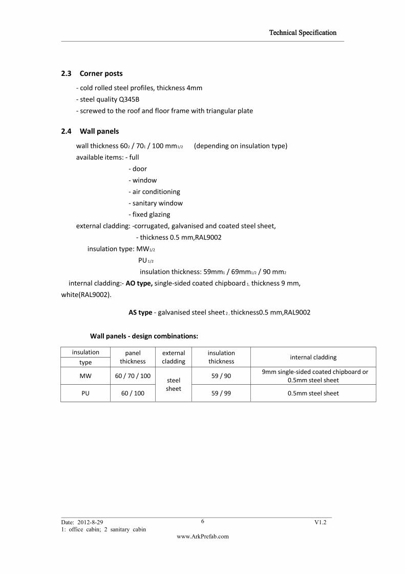
2.3 Corner posts
- cold rolled steel profiles, thickness 4mm
- steel quality Q345B
- screwed to the roof and floor frame with triangular plate
2.4 Wall panels
wall thickness 602 / 701 / 100 mm1/2 (depending on insulation type)
available items: - full
- door
- window
- air conditioning
- sanitary window
- fixed glazing
external cladding: -corrugated, galvanised and coated steel sheet,
- thickness 0.5 mm,RAL9002
insulation type: MW1/2
PU 1/2
insulation thickness: 59mm1 / 69mm1/2 / 90 mm2
internal cladding:- AO type, single-sided coated chipboard 1, thickness 9 mm,
white(RAL9002).
AS type - galvanised steel sheet 2 , thickness0.5 mm,RAL9002
Wall panels - design combinations:
insulation panelthickness
externalcladding
insulationthickness
internal claddingtype
MW 60 / 70 / 100steelsheet
59 / 909mm single-sided coated chipboard or
0.5mm steel sheet
PU 60 / 100 59 / 99 0.5mm steel sheet

Technical Specification
Date: 2012-8-29 V1.2 V1.21: office cabin; 2 sanitary cabin
www.ArkPrefab.com
7
2.5 Partition walls
available items: - full panel
- door panel
- window panel
- half panel
wooden construction1 :AO Type :
- total thickness 60 mm
- frame: wooden frame, thickness 40 mm
- cladding on one side: single-sided coated chipboard
- 9 mm thick, white
steel version 2 AS Type:- total thickness 60 mm
- insulation: MW 60mm thick, density:120kg/m³
PU 60mm thick, density:40kg/m³
cladding on both sides: laminated steel plate, thickness 0.5 mm
colour: white (similar RAL 9002)
2.6 Doors
- right or left hand hinged
- inward or outward opening
- steel frame with triangular wrap-around sealing
- door blade with galvanised steel sheets on both sides
-insulated with honeycomb
Dimensions:
nominal dimension clear opening
Aluminum Door
625x2,040
870x2,040
1500x2,040
Steel Door870x1,995
1,400x1,995
2.7 Window
design office window:
- pvc frame with insulated glazing and integrated Aluminum roller shutters
- colour:white
- roller shutter housing with belt take-up reel and forced ventilations:
- one hand tilt & turn mechanism
nominal dimension clear opening
Sliding window, double glazed glass, 4/9/4 800x1,100

Technical Specification
Date: 2012-8-29 V1.2 V1.21: office cabin; 2 sanitary cabin
www.ArkPrefab.com
8
Tilt/swing window,double glazed glass, 4/9/4 900*1200
Top hinged window 652x714
Window parapet :( vertical distance between floor level and the upper edge of the lower profile of
the window frame)
office window (CAH 2,610 mm) 800mm
office window (CAH 2,810 mm) 950mm
sanitary window 1400mm

Technical Specification
Date: 2012-8-29 V1.2 V1.21: office cabin; 2 sanitary cabin
www.ArkPrefab.com
9
3 Electrical installationSpecification: concealed cabling
IP20¹/IP44²
plug insert according to country standards
country specific design / variations possible
Technical data:
basis VDE (= OEVE, SKAN, CZ/SK) F GB CH, DK
connection: recessed CEE external plug and socket connections
voltage:230V/3 poles/ 32 A1/2
400V/5 poles/ 32 A1/2
frequency 50HZ
protection residual current operated device 40 A/0,03 A , 4 poles (400 V)
residual current operated device 40 A/0,03 A, 2 poles (230 V)
distribution boarddistribution box, surface mounted type, single row
distribution box, surface mounted type
electrical circuits
light circuit breaker 10A,1p+N poles (3x1.5mm²)1/2
heating circuit breaker 16A, 1p+N poles (3x2.5mm²)1/2
socket circuit breaker 16A, 1p+N poles (3x2.5mm²)1/2
socket 4 single sockets
lightinglight switch1/2
2 twin batten fluorescent light tubes with plastic covering 2x36w¹
Electrical Regulations:
- CE regulation
- EN61000-6-3:2007
- EN61000-6-1:2007
- UL1581
- AS/NZS5000.2:2006
- VDZ0295/IEC228
earthing: - universally usable grounding terminal:
- On both short sides in the floor frame of each corner a drill hole with a diameter
of 10 mm is prepared for the fixture of the grounding terminal.
- The fitting of the grounding terminal is undertaken with a screw M10 with a
self-cutting screw thread. The positioning of the screw is carried out in the factory
on a suitable spot of the cabin.
- A grounding terminal and a four-wire connector are delivered with the container
and need to be fitted by the customer on site.
- The protective earthing installation on site must be carried out by the
buyer/hirer.

Technical Specification
Date: 2012-8-29 V1.2 V1.21: office cabin; 2 sanitary cabin
www.ArkPrefab.com
10
Wiring: - Fixed cabling depending on the panel configuration and the user 1 / 2
- Flexible cable system with plug contact and cables in full length 1 / 2
Safety advice: The cabins can be linked electrically at the external CEE plugs and sockets. For
the decision how many units to connect electrically the expected constant
current in the link circuits has to be considered. The commissioning has to
be carried out by an approved electrician.
The manual for the assembly, start up, utilisation and maintenance of the
electrical installations is delivered in the fuse box and needs to be
followed!
Before connecting the cabin to the supplying low voltage grid all appliances
(consumer loads) need to be switched off and earthing needs to be ensured
(earthing feed cable and earthing connecting lines between the cabins need
to be checked on potential equity and low Ohm level).
Attention : The supply- and connection cables are made for an operating voltage of max.
32 Ampere. These aren't secured with a overcurrent protection device. The
connection of the cabins to the external electrical power supply only may be
undertaken by an authorised specialist company.
Before using the cabin (modular building) for the first time the effectiveness
of the protection measures for the fault protection need to be checked by an
authorized specialist company.
Cleaning with a high-pressure cleaner is FORBIDDEN.
The electrical equipment of the cabin may not be cleaned by a direct
water jet under any circumstances.
If the containers are delivered into areas with increased lightning activity
further measurements have to be taken under account to prevent
overvoltage depending on the country specific rules.
In case machines or appliances with high starting current peaks are used
(according to the manual of the respective appliances) adequate
RCD/MCB must be used.
The electric fittings of the cabins are designed for minimal vibration
exposure. If the exposure is higher measurements need to be taken
depending on country specific rules.
The cabins are designed for areas with little seismic activity. If the cabins
are used in areas with higher seismic activity, the country's national
regulations are valid and the equipment needs to be adjusted
accordingly
The choice of the external linking cables of the cabins has to suit the
country's national technical regulations.
The cabins have to be secured against thermal overload with a type gL
fuse or gG with max. IN = 32A.
Technical Specification
Date: 2012-8-29 V1.2 V1.21: office cabin; 2 sanitary cabin
www.ArkPrefab.com
11
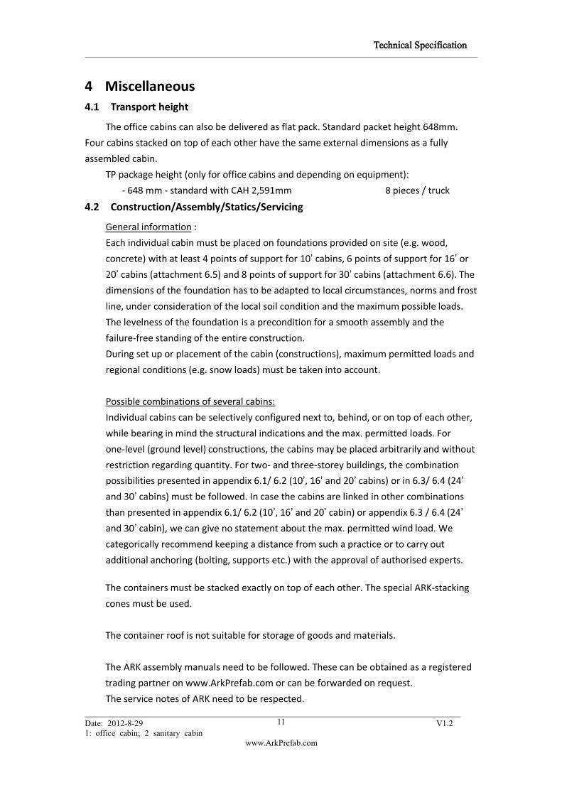
4 Miscellaneous4.1 Transport height
The office cabins can also be delivered as flat pack. Standard packet height 648mm.
Four cabins stacked on top of each other have the same external dimensions as a fully
assembled cabin.
TP package height (only for office cabins and depending on equipment):
- 648 mm - standard with CAH 2,591mm 8 pieces / truck
4.2 Construction/Assembly/Statics/Servicing
General information :
Each individual cabin must be placed on foundations provided on site (e.g. wood,
concrete) with at least 4 points of support for 10’ cabins, 6 points of support for 16’ or20’ cabins (attachment 6.5) and 8 points of support for 30’ cabins (attachment 6.6). The
dimensions of the foundation has to be adapted to local circumstances, norms and frost
line, under consideration of the local soil condition and the maximum possible loads.
The levelness of the foundation is a precondition for a smooth assembly and the
failure-free standing of the entire construction.
During set up or placement of the cabin (constructions), maximum permitted loads and
regional conditions (e.g. snow loads) must be taken into account.
Possible combinations of several cabins:
Individual cabins can be selectively configured next to, behind, or on top of each other,
while bearing in mind the structural indications and the max. permitted loads. For
one-level (ground level) constructions, the cabins may be placed arbitrarily and without
restriction regarding quantity. For two- and three-storey buildings, the combination
possibilities presented in appendix 6.1/ 6.2 (10’, 16’ and 20’ cabins) or in 6.3/ 6.4 (24’and 30’ cabins) must be followed. In case the cabins are linked in other combinations
than presented in appendix 6.1/ 6.2 (10’, 16’ and 20’ cabin) or appendix 6.3 / 6.4 (24’and 30’ cabin), we can give no statement about the max. permitted wind load. We
categorically recommend keeping a distance from such a practice or to carry out
additional anchoring (bolting, supports etc.) with the approval of authorised experts.
The containers must be stacked exactly on top of each other. The special ARK-stacking
cones must be used.
The container roof is not suitable for storage of goods and materials.
The ARK assembly manuals need to be followed. These can be obtained as a registered
trading partner on www.ArkPrefab.com or can be forwarded on request.
The service notes of ARK need to be respected.

Technical Specification
Date: 2012-8-29 V1.2 V1.21: office cabin; 2 sanitary cabin
www.ArkPrefab.com
12
Sanitary fittings:
After connecting with the water supply the entire water circulation should be checked
once more on water tightness (possible loosening during transport).
ARK denies any warranty for damages, which may result from placement contrary to
the principles.
Liability for consequential damages is excluded on principle.
4.3 Handling
- with fork lift
- with crane: angle between lifting rope and horizontal line must be at least 60 °Due to construction and design, handling with spreader is not allowed.
4.4 Certification
ABS Lloyd 'type test'
4.5 Paint
Paint system with high weather and aging durability, suitable for city and
industry atmosphere.
Wall panels: 45 µm coating thickness
frame: 20-40 µm grounding
40-50 µm top coat
The painting of above mentioned parts is carried out with different types of
production. These achieve shades similar to RAL. We do not accept liability for colour
variations in comparison with the RAL tones.

Technical Specification
Date: 2012-8-29 V1.2 V1.21: office cabin; 2 sanitary cabin
www.ArkPrefab.com
13
5 Water installation
supply supply using½“,¾“ or 1" pipe, sideways through cabin wall
internal: - PPR pipework for ingoing water
- PVC pipework for outgoing water
operating pressure max. permitted operating / connection pressure - 4 bar warm
water preparation: by using electric boilers, depending on the cabin type (80, 150 or
300² liters)
ATTENTION:
The boilers with 80/150/300 l capacity are suitable for a max. operating pressure
of 6 bar. A higher water pressure is reduced with an appropriate pressure reducing
valve!
discharge: The waste water is collected via PVC pipes, DN 50, DN 100 (external diameter Ø50, 110 mm) and discharged sideways through the cabin wall. The discharge of
the waste water into an authorised sewage network has to be undertaken by the
buyer/hirer in compliance with the official regulations for waste and faecal water.
Further technical information upon request.
Regulatory and legal requirements for the storage, placement and usage of the
containers must be considered by the buyer/hirer.
The suitability of the container (modular building) and of the possibly also
supplied options (e.g. stairs, air conditionings etc.) needs to be examined by the
purchaser / hirer for the intended purpose.
Subject to technical alterations.
Technical Specification
Date: 2012-8-29 V1.2 V1.21: office cabin; 2 sanitary cabin
www.ArkPrefab.com
14
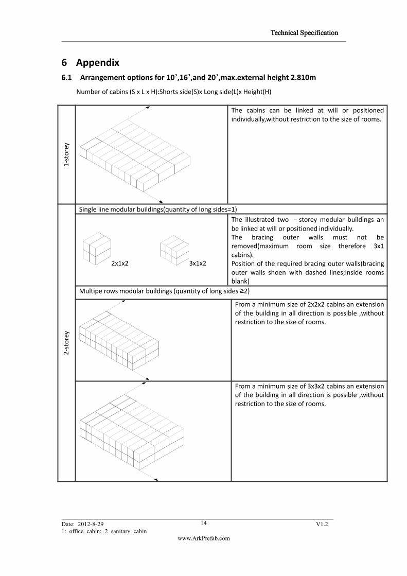
6 Appendix6.1 Arrangement options for 10’,16’,and 20’,max.external height 2.810m
Number of cabins (S x L x H):Shorts side(S)x Long side(L)x Height(H)
1-storey
The cabins can be linked at will or positionedindividually,without restriction to the size of rooms.
2-storey
Single line modular buildings(quantity of long sides=1)
2x1x2 3x1x2
The illustrated two –storey modular buildings anbe linked at will or positioned individually.The bracing outer walls must not beremoved(maximum room size therefore 3x1cabins).Position of the required bracing outer walls(bracingouter walls shoen with dashed lines;inside roomsblank)
Multipe rows modular buildings (quantity of long sides ≥2)
From a minimum size of 2x2x2 cabins an extensionof the building in all direction is possible ,withoutrestriction to the size of rooms.
From a minimum size of 3x3x2 cabins an extensionof the building in all direction is possible ,withoutrestriction to the size of rooms.

Technical Specification
Date: 2012-8-29 V1.2 V1.21: office cabin; 2 sanitary cabin
www.ArkPrefab.com
15
3-storey
3x1x3 3x2x3
The illustrated three –storey modular buildingscan be linked at will or positioned individually.The bracing outer walls must not beremoved(maximum room size therefore 3x2cabins).Position of the required bracing outerwalls(bracing outer walls shoen with dashedlines;inside rooms blank)
6.2 Standard foundation plan for 10’,16’,and 20’ cabin
Each individual cabin must be placed on foundations provided on site with at least 4 pointsof support for 10’ cabins, 6 points of support for 16’ or 20’ cabins. The smallest foundationsize is 30 x 30 cm, but dimensions of the foundation have to be adapted to localcircumstances, norms and frost line, under consideration of the local soil condition and themaximum possible loads. These measures have to be undertaken by the buyer/hirer.Cabin length(L); Cabin width(B)
Fore
xample:sing
leun
it
LEGEND:
Foundation points for 10’,16’,and20’cabin
Foundation points for 16’and20’cabin
Fore
xample:combina
tionwith
4cabins
When combining several cabins higher loads at the inner foundation points have to be considered –asillustrated.The support post must be used at an open long side joint .The support post may be positioned anywherebetween the middle foundations on an additional foundation point.
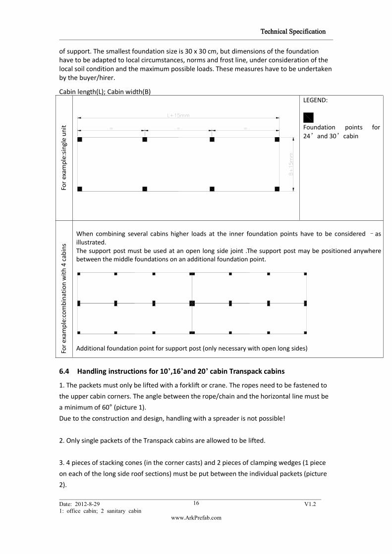
6.3 Standard foundation plan for 24’and 30’ cabin
Each individual cabin must be placed on foundations provided on site with at least 8 points
Technical Specification
Date: 2012-8-29 V1.2 V1.21: office cabin; 2 sanitary cabin
www.ArkPrefab.com
16
of support. The smallest foundation size is 30 x 30 cm, but dimensions of the foundationhave to be adapted to local circumstances, norms and frost line, under consideration of thelocal soil condition and the maximum possible loads. These measures have to be undertakenby the buyer/hirer.
Cabin length(L); Cabin width(B)
Forexam
ple:sing
leun
it
LEGEND:
Foundation points for24’and 30’cabin
Fore
xample:combina
tionwith
4cabins
When combining several cabins higher loads at the inner foundation points have to be considered –asillustrated.The support post must be used at an open long side joint .The support post may be positioned anywherebetween the middle foundations on an additional foundation point.
Additional foundation point for support post (only necessary with open long sides)
6.4 Handling instructions for 10’,16’and 20’ cabin Transpack cabins
1. The packets must only be lifted with a forklift or crane. The ropes need to be fastened to
the upper cabin corners. The angle between the rope/chain and the horizontal line must be
a minimum of 60° (picture 1).Due to the construction and design, handling with a spreader is not possible!
2. Only single packets of the Transpack cabins are allowed to be lifted.
3. 4 pieces of stacking cones (in the corner casts) and 2 pieces of clamping wedges (1 piece
on each of the long side roof sections) must be put between the individual packets (picture
2).

Technical Specification
Date: 2012-8-29 V1.2 V1.21: office cabin; 2 sanitary cabin
www.ArkPrefab.com
17
4. Do not place any extra weight on the top packet!
5. You must only stack max. 4 packets on top of each other.
Possible packet heights:
- 648mm - Standard with external cabin height 2,610 mm and 2,810 mm
6.5 Handling instructions for 24’and 30’ cabin Transpack cabins
1. The packets must only be lifted with a forklift or crane. The ropes/chains must be fastened
on the crane hooks screwed to the top frame. The angle between the rope/chain and the
horizontal line must be a minimum of 60° (picture 1).Due to the construction and design, handling with a spreader is not possible.
2. Only single packets of the Transpack cabins are allowed to be lifted.
3. 4 pieces of stacking cones (in the corner casts) and 4 pieces of clamping wedges (2 piece
on each of the longside roof sections) must be put between the individual packets (picture
2).
4. Do not place any extra weight on the top packet!
5. You must only stack max. 4 packets on top of each other.
Possible packet heights:
- 648mm - Standard with external cabin height 2,610 mm and 2,810 mm

Technical Specification
Date: 2012-8-29 V1.2 V1.21: office cabin; 2 sanitary cabin
www.ArkPrefab.com
18