Embed Size (px)
Citation preview
11921 Rockville Pike, Suite 100, Rockville, MD 20852 Phone: 301-984-4400, Fax: 301-984-7600 Administration by EXCEL Services Corporation
TECHNICAL SPECIFICATIONS TASK FORCEA JOINT OWNERS GROUP ACTIVITYTSTF
December 22, 2009 TSTF-09-25 PROJ0753 U. S. Nuclear Regulatory Commission Attn: Document Control Desk Washington, DC 20555-0001 SUBJECT: Transmittal of Revised Risk-Informed End State Travelers REFERENCES: 1. Letter from Bruce A. Boger (NRC) to the Technical Specifications Task
Force, "Requested Revision of Risk-Informed End States in Standard Technical Specifications," dated July 13, 2009.
2. Letter from Joseph F. Williams (NRC) to the Technical Specification Task
Force, "Implementation of TSTF-423 Revision 0, "Technical Specification End States, NEDC-32998-A," dated May 5, 2009.
In Reference 1, the NRC requested that the TSTF prepare and submit revisions to the TSTF Travelers that implement Risk-Informed Technical Specification Task Force (RITSTF) Initiative 1, "Technical Specification Actions End States Modifications," to address a potential safety issue identified during plant-specific reviews. The NRC's request affects two approved Travelers: TSTF-422-A, "Change in Technical Specifications End States (CE NPSD-1186)," and TSTF-423-A, "Technical Specifications End States, NEDC-32988-A," and one Traveler currently under NRC review: TSTF-431, "Change in Technical Specifications End States (BAW-2441)." These Travelers are applicable to Combustion Engineering (CE), boiling water (BWR), and Babcock & Wilcox (B&W) reactors, respectively. As requested, all three Travelers have been modified to include a Required Action note which prohibits the use of LCO 3.0.4.a when entering the preferred end state (Mode 3 for BWR plants and Mode 4 for CE and B&W plants). The revision to TSTF-423-A also implements the change requested in Reference 2. The change to the primary containment end state is eliminated. The requested changes also affect the implementation guidance documents (referenced in the model Safety Evaluations in the Notices of Availability published in the Federal Register for TSTF-422 (WCAP-16364), TSTF-423 (TSTF-IG-05-02), and TSTF-431 (TSTF-IG-07-01). The documents TSTF-IG-05-02, Rev. 2, and TSTF-IG-07-01, Rev. 1, are enclosed. The revised
TSTF 09-25 December 22, 2009
Page 2
TSTF-422 implementation guidance (WCAP-16364) will be transmitted separately by the Pressurized Water Reactor Owners Group. As stated in Reference 1, NRC review of these Travelers is exempt from NRC review fees in accordance 10 CFR 170.11(a)(1)(ii). The TSTF is also submitting TSTF-432, "Change in Technical Specifications End States (WCAP-16294)." This Traveler implements RITSTF Initiative 1 for Westinghouse plants, and completes the implementation of Initiative 1. TSTF-432 includes the requested prohibition on the use LCO 3.0.4.a for the revised Required Actions. The TSTF-432 implementation guidance will be transmitted separately by the Pressurized Water Reactor Owners Group. The review of TSTF-432 is also exempt from NRC review fees under 10 CFR 170. All RITSTF Initiative 1 Travelers have been exempt from NRC review fees in accordance with the January 10, 2003 letter from William D. Beckner (NRC) to Tony Pietrangelo (Nuclear Energy Institute). Should you have any questions, please do not hesitate to contact us. Kenneth J. Schrader (PWROG/W) Donald W. Gregoire (BWROG) Thomas W. Raidy (PWROG/CE) Wendy E. Croft (PWROG/B&W) Enclosures: TSTF-422, Rev. 2 TSTF-423, Rev. 1 TSTF-431, Rev. 3 TSTF-432, Rev. 0 TSTF-IG-05-02, Rev. 2 TSTF-IG-07-01, Rev. 1 cc: Robert Elliott, Technical Specifications Branch, NRC Michelle Honcharik, Special Projects Branch, NRC

Page 1
TSTF-422, Rev. 2CEOG-152, Rev. 1
NUREGs Affected:
Change in Technical Specifications End States (CE NPSD-1186)
Technical Specification Task ForceImproved Standard Technical Specifications Change Traveler
1430 1431 1432 1433 1434
Classification 1) Technical Change Recommended for CLIIP?:
Industry Contact: Tom Raidy, (949) 368-7582, [email protected]
Yes
Correction or Improvement: Improvement NRC Fee Status: Exempt
Benefit: Shortens Outages
1.0 Description
CE NPSD-1186, "Technical Justification for the Risk Informed Modification to Selected Action End States for CEOG PWRs, April 2000, modified the end state technical specification (TS) for numerous allowed outage time (AOT) requirements. Most of the requested TS changes are to permit an end state of hot shutdown (Mode 4) rather than the cold shutdown (Mode 5) end state that is contained in the current TSs. In addition, the revised Required Actions are modified by a Note that prohibits the use of the provisions of LCO 3.0.4.a to enter the end state Mode of Applicability during startup.
There are differences between the Topical Report, the NRC's Safety Evaluation, and this proposed change. These differences are described and justified in Attachment 1.
22-Dec-09Traveler Rev. 3. Copyright (C) 2006, EXCEL Services Corporation. Use by EXCEL Services associates, utility clients, and the U.S. Nuclear Regulatory Commission is granted. All other use without written permission is prohibited.
TSTF-422, Rev. 2CEOG-152, Rev. 1
2.0 Proposed Change
This Traveler implements the changes described in CE NPSD-1186 and approved by the NRC on July 17, 2001. Twenty-six specifications are affected:3.3.5 (analog) ESFAS Logic and Manual Trip3.3.6 (digital) ESFAS Logic and Manual Trip3.3.8 (digital) CPIS3.3.8 (analog), 3.3.9 (digital) CRIS3.3.9 (analog), CVCS Isolation Signal3.3.10 (analog), Shield Building Filtration Actuation Signal3.4.6, RCS Loops - MODE 43.5.4, RWT3.6.2, Containment Air Locks3.6.3, Containment Isolation Valves3.6.4, Containment Pressure3.6.5, Containment Air Temperature3.6.6A, Containment Spray and Cooling Systems (Atmospheric and Dual) Credit taken for iodine removal by the Containment Spray System3.6.6B, Containment Spray and Cooling Systems (Atmospheric and Dual) Credit not taken for iodine removal by the Containment Spray System3.6.11, Shield Building (Dual)3.7.7, Component Cooling Water System3.7.8, Service Water System3.7.9, Ultimate Heat Sink3.7.10, Essential Chilled Water3.7.11, CREACS3.7.12, CREATCS3.7.13, ECCS PREACS3.7.15, PREACS3.8.1, AC Sources - Operating3.8.4, DC Sources - Operating3.8.7, Inverters - Operating
Revision 1 of TSTF-422 changes the proposed Technical Specifications and Bases in response to an NRC request. In a letter dated July 13, 2009 from Bruce A. Boger (NRC) to the TSTF, the NRC requested that the TSTF revise TSTF-422 to prevent inappropriate use of LCO 3.0.4.a during startup to go up in the preferred end state Mode with inoperable systems or equipment. The Traveler has been revised to modify every Required Action with the preferred end state with the Note "LCO 3.0.4.a is not applicable when entering MODE 4." The Bases of each Required Action is revised to describe the Note. This does not affect the justification of the change.
22-Dec-09Traveler Rev. 3. Copyright (C) 2006, EXCEL Services Corporation. Use by EXCEL Services associates, utility clients, and the U.S. Nuclear Regulatory Commission is granted. All other use without written permission is prohibited.
TSTF-422, Rev. 2CEOG-152, Rev. 1
3.0 Background
CE NPSD-1186, "Technical Justification for the Risk Informed Modification to Selected Action End States for CEOG PWRs, April 2000, modified the end state technical specification (TS) for numerous Required Actions. Most of the requested TS changes are to permit an end state of hot shutdown (Mode 4) rather than the cold shutdown (Mode 5) end state that is contained in the current TSs.
22-Dec-09Traveler Rev. 3. Copyright (C) 2006, EXCEL Services Corporation. Use by EXCEL Services associates, utility clients, and the U.S. Nuclear Regulatory Commission is granted. All other use without written permission is prohibited.
TSTF-422, Rev. 2CEOG-152, Rev. 1
4.0 Technical Analysis
CE NPSD-1186 presented recommendations for replacing cold shutdown (MODE 5) Required Actions with hot shutdown (MODE 4) Required Actions for a large number of Specifications. Preventing plant challenges during shutdown conditions has been, and continues to be, an important aspect of ensuring safe operation of the plant. Past events demonstrate that risk of core damage associated with entry into, and operation in, shutdown cooling is not negligible and should be considered when a plant is required to shutdown. Therefore, the Technical Specifications should encourage plant operation in the steam generator heat removal mode whenever practical, and require reliance on shutdown cooling only when it is a risk beneficial alternative to other actions. CE NPSD-1186 justified remaining in hot shutdown for the subject Specifications. CE NPSD-1186 was approved by the NRC on July 17, 2001.
The justification of these changes is described in CE NPSD-1186, which demonstrates through probabilistic and deterministic safety evaluations that the proposed end states represent a condition of equal or lower risk than the original end states, and the NRC's Safety Evaluation dated July 17, 2001. In several cases, the change requested in the Topical Report differs from the change approved in the Safety Evaluation. In addition, in many cases the Topical Report and the Safety Evaluation apply conditions on the use of the new end states which are not amenable to incorporation in the Technical Specifications. Attachment 1 discusses the conditions listed in the Safety Evaluation and differences between the proposed change and the Topical Report or Safety Evaluation that were made to facilitate the application of the change to the Improved Technical Specifications.
The revised Required Actions are also modified by the addition of a Note prohibiting entry into the end state Mode of Applicability during startup using the provisions of LCO 3.0.4.a. The purpose of this Note is to provide assurance that entry into the end state Mode of Applicability during startup is not made without the appropriate risk assessment. Entry into the end state Mode of Applicability during startup will still be allowed under the provisions of LCO 3.0.4.b. This is acceptable because LCO 3.0.4.b allows entry only after performance of a risk assessment addressing inoperable systems and components, consideration of the results, determination of the acceptability of entering the MODE or other specified condition in the Applicability, and establishment of risk management actions, if appropriate. Details of the risk assessment are provided in the Bases for LCO 3.0.4.b.
Licensees adopting the end states proposed in this Traveler must commit to performing a risk assessment in accordance with 10 CFR 50.65(a)(4) when using the end states regardless of whether maintenance is being performed. This risk assessment must follow Regulatory Guide 1.182, “Assessing and Managing Risk Before Maintenance Activities at Nuclear Power Plants,” which endorses NUMARC 93-01, “Industry Guideline for Monitoring the Effectiveness of Maintenance at Nuclear Power Plants,” Section 11 guidance for implementation of 10 CFR 50.65(a)(4). Licensees must also commit to following the industry-developed implementation guidance, WCAP-16364-NP, Revision 0, "Implementation Guidance for Risk Informed Modification to Selected Required Action End States at Combustion Engineering NSSS Plants (TSTF-422)," November 2004.
22-Dec-09Traveler Rev. 3. Copyright (C) 2006, EXCEL Services Corporation. Use by EXCEL Services associates, utility clients, and the U.S. Nuclear Regulatory Commission is granted. All other use without written permission is prohibited.
TSTF-422, Rev. 2CEOG-152, Rev. 1
5.1 No Significant Hazards Consideration
The TSTF has evaluated whether or not a significant hazards consideration is involved with the proposed generic change by focusing on the three standards set forth in 10 CFR 50.92, “Issuance of amendment,” as discussed below:
1. Does the proposed change involve a significant increase in the probability or consequences of an accident previously evaluated?
Response: No.
Required Actions are not an initiator of any accident previously evaluated Therefore, the proposed changes do not affect the probability of any accident previously evaluated. CE NPSD-1186 demonstrated that the proposed changes in the required end state do not significantly increase the consequences of any accidents previously evaluated.
Therefore, the proposed change does not involve a significant increase in the probability or consequences of an accident previously evaluated.
2. Does the proposed change create the possibility of a new or different kind of accident from any accident previously evaluated?
The changes do not involve a physical alteration of the plant (i.e., no new or different type ofequipment will be installed) or a change in the methods governing normal plant operation. Inaddition, the changes do not impose any new or different requirements. The changes do not alterassumptions made in the safety analysis.
Response: No.
Therefore, the proposed change does not create the possibility of a new or different kind of accident from any previously evaluated.
3. Does the proposed change involve a significant reduction in a margin of safety?
Response: No.
CE NPSD-1186 demonstrated that the changed end states represent a condition of equal or lower risk than the original end states.
Therefore, the proposed change does not involve a significant reduction in a margin of safety.
Based on the above, the TSTF concludes that the proposed change presents no significant hazards consideration under the standards set forth in 10 CFR 50.92(c), and, accordingly, a finding of “no significant hazards consideration” is justified.
22-Dec-09Traveler Rev. 3. Copyright (C) 2006, EXCEL Services Corporation. Use by EXCEL Services associates, utility clients, and the U.S. Nuclear Regulatory Commission is granted. All other use without written permission is prohibited.
TSTF-422, Rev. 2CEOG-152, Rev. 1
5.2 Applicable Regulatory Requirements/Criteria
Required Actions are not specified by any regulatory requirement or criteria. The Limiting Conditions for Operation, which are based on accident analysis assumptions and regulatory requirements are not affected by this change. Therefore, no regulatory requirements or criteria are affected by this change.
In conclusion, based on the considerations discussed above, (1) there is reasonable assurance that the health and safety of the public will not be endangered by operation in the proposed manner, (2) such activities will be conducted in compliance with the Commission’s regulations, and (3) the approval of the proposed change will not be inimical to the common defense and security or to the health and safety of the public.
6.0 Environmental Consideration
A review has determined that the proposed change would change a requirement with respect to installation or use of a facility component located within the restricted area, as defined in 10 CFR 20, or would change an inspection or surveillance requirement. However, the proposed change does not involve (i) a significant hazards consideration, (ii) a significant change in the types or significant increase in the amounts of any effluent that may be released offsite, or (iii) a significant increase in individual or cumulative occupational radiation exposure. Accordingly, the proposed change meets the eligibility criterion for categorical exclusion set forth in 10 CFR 51.22(c)(9). Therefore, pursuant to 10 CFR 51.22(b), no environmental impact statement or environmental assessment need be prepared in connection with the proposed change.
7.0 References
1. CE NPSD-1186, "Technical Justification for the Risk Informed Modification to Selected Action End States for CEOG PWRs, April 2000.
Revision History
OG Revision 0 Revision Status: Closed
Original IssueRevision Description:
Revision Proposed by: CEOG
Owners Group Review InformationDate Originated by OG: 11-Jul-00
Owners Group CommentsApproved with modifications.
Date: 11-Jul-00Owners Group Resolution: Approved
TSTF Review Information
TSTF Received Date: 11-Jul-00 Date Distributed for Review
22-Dec-09Traveler Rev. 3. Copyright (C) 2006, EXCEL Services Corporation. Use by EXCEL Services associates, utility clients, and the U.S. Nuclear Regulatory Commission is granted. All other use without written permission is prohibited.
TSTF-422, Rev. 2CEOG-152, Rev. 1
OG Revision 0 Revision Status: Closed
TSTF Comments:
(No Comments)
Date:TSTF Resolution: Superceeded
OG Review Completed: BWOG CEOGWOG BWROG
OG Revision 1 Revision Status: Closed
Complete replacement of Revision 0. Revision 1 is based on the approved Topical and NRC's Safety Evaluation.
Revision Description:
Revision Proposed by: CEOG
Owners Group Review InformationDate Originated by OG: 01-Aug-01
Owners Group Comments(No Comments)
Date: 30-Jan-02Owners Group Resolution: Approved
TSTF Review Information
TSTF Received Date: 30-Jan-02 Date Distributed for Review 10-May-02
TSTF Comments:
1/30/2002 - Currently under review by RITSTF to incorporate information requested by NRC.4/28/2002 - Incorporated RITSTF comments to address NRC requests.
Date: 03-Jun-02TSTF Resolution: Approved
OG Review Completed: BWOG CEOGWOG BWROG
NRC Review InformationNRC Received Date: 03-Jun-02
In verbal comments, the NRC questioned whether the revised end state applies to any conditions in which there is a loss of function. TSTF agreed to review and, if needed, revise.
08-Dec-02NRC Requests Changes: TSTF Will Revise
NRC Comments:
Final Resolution: Final Resolution Date:
TSTF Revision 1 Revision Status: Closed
Based on NRC verbal comments, the TSTF reviewed the proposed changes against the Safety Evalution to determine if the MODE 4 end state was being applied to conditions in which there is a Loss of LCO Safety Function (e.g., none of the safety functions required by the LCO can be performed) that was not evaluated in the Safety Evaluation.
Revision Description:
Revision Proposed by: TSTF
22-Dec-09Traveler Rev. 3. Copyright (C) 2006, EXCEL Services Corporation. Use by EXCEL Services associates, utility clients, and the U.S. Nuclear Regulatory Commission is granted. All other use without written permission is prohibited.
TSTF-422, Rev. 2CEOG-152, Rev. 1
TSTF Revision 1 Revision Status: Closed
Two instances were discovered: 3.3.5 (analog), ESFAS Instruments, and 3.3.9 (analog), CVCS Isolation Signal.
Those two Specifications were revised to create a new Action for the MODE 4 end state and the existing MODE 5 end state was retained for a Loss of LCO Safety Function..
Attachment 1 was revised to incorporate the results of the review for each affected specification.
TSTF Review Information
TSTF Received Date: 13-Jan-03 Date Distributed for Review 13-Jan-03
TSTF Comments:
(No Comments)
Date: 20-Jan-03TSTF Resolution: Approved
OG Review Completed: BWOG CEOGWOG BWROG
NRC Review Information
NRC Received Date: 21-Jan-03
In a letter dated June 23, 2003, the NRC requested changes to TSTF-422. Subsequently, the NRC withdrew those changes and instead the information is being placed in an implementation guidance document.
FRN for comment issued on 5/4/05.
FRN Notice of Availability issued on 7/5/05.
05-Jul-05Superceded by Revision
NRC Comments:
Final Resolution: Final Resolution Date:
Date of NRC Letter: 05-Jul-05
TSTF Revision 2 Revision Status: Active
In a letter dated July 13, 2009 from Bruce A. Boger (NRC) to the TSTF, the NRC requested that the TSTF revise TSTF-422 to prevent inappropriate use of LCO 3.0.4.a during startup to go up in the preferred end state Mode with inoperable systems or equipment. The Traveler has been revised to modify every Required Action with the preferred end state with the Note "LCO 3.0.4.a is not applicable when entering MODE 4." The Bases of each Required Action is revised to describe the Note.
TSTF-422 was presented as hand-marked changes to NUREG-1432, Revision 2, pages. TSTF-422, Revision 2, follows the current practice of presenting the changes as electronic changes to Revision 3.1 of NUREG-1432. There were no other Travelers incorporated into the NUREGs between Revision 2 and Revision 3.1 that affected the markups for TSTF-422.
Revision Description:
Revision Proposed by: NRC
22-Dec-09Traveler Rev. 3. Copyright (C) 2006, EXCEL Services Corporation. Use by EXCEL Services associates, utility clients, and the U.S. Nuclear Regulatory Commission is granted. All other use without written permission is prohibited.
TSTF-422, Rev. 2CEOG-152, Rev. 1
Affected Technical Specifications
TSTF Revision 2 Revision Status: Active
Owners Group Review InformationDate Originated by OG: 02-Nov-09
Owners Group Comments(No Comments)
Date: 16-Nov-09Owners Group Resolution: Approved
TSTF Review Information
TSTF Received Date: 16-Nov-09 Date Distributed for Review 14-Dec-09
TSTF Comments:
(No Comments)
Date: 22-Dec-09TSTF Resolution: Approved
OG Review Completed: BWOG CEOGWOG BWROG
NRC Review InformationNRC Received Date: 22-Dec-09
Ref. 3.3.5 Bases ESFAS Logic and Manual Trip (Analog)
Action 3.3.5.D
NewChange Description:
ESFAS Logic and Manual Trip (Analog)
Action 3.3.5.D
Renamed EChange Description:
ESFAS Logic and Manual Trip (Analog)
Action 3.3.5.D Bases
Renamed EChange Description:
ESFAS Logic and Manual Trip (Analog)
Action 3.3.5.D Bases
NewChange Description:
ESFAS Logic and Manual Trip (Analog)
SR 3.3.5.1 Bases ESFAS Logic and Manual Trip (Analog)
Ref. 3.3.6 Bases ESFAS Logic and Manual Trip (Digital)
Action 3.3.6.E ESFAS Logic and Manual Trip (Digital)
Action 3.3.6.E Bases ESFAS Logic and Manual Trip (Digital)
22-Dec-09Traveler Rev. 3. Copyright (C) 2006, EXCEL Services Corporation. Use by EXCEL Services associates, utility clients, and the U.S. Nuclear Regulatory Commission is granted. All other use without written permission is prohibited.
TSTF-422, Rev. 2CEOG-152, Rev. 1
Action 3.3.6.F
DeletedChange Description:
ESFAS Logic and Manual Trip (Digital)
Action 3.3.6.F Bases
DeletedChange Description:
ESFAS Logic and Manual Trip (Digital)
SR 3.3.6.1 Bases ESFAS Logic and Manual Trip (Digital)
Ref. 3.3.8 Bases CPIS (Digital)
Ref. 3.3.8 Bases CRIS (Analog)
Action 3.3.8.B CPIS (Digital)
Action 3.3.8.B CRIS (Analog)
Action 3.3.8.B Bases CPIS (Digital)
Action 3.3.8.B Bases CRIS (Analog)
SR 3.3.8.2 Bases CRIS (Analog)
SR 3.3.8.4 Bases CPIS (Digital)
SR 3.3.8.4 Bases CRIS (Analog)
SR 3.3.8.6 Bases CPIS (Digital)
Ref. 3.3.9 Bases CRIS (Digital)
Ref. 3.3.9 Bases CVCS Isolation Signal (Analog)
Action 3.3.9.B CRIS (Digital)
Action 3.3.9.B Bases CRIS (Digital)
Action 3.3.9.D
Renamed EChange Description:
CVCS Isolation Signal (Analog)
Action 3.3.9.D
NewChange Description:
CVCS Isolation Signal (Analog)
Action 3.3.9.D Bases
Renamed EChange Description:
CVCS Isolation Signal (Analog)
Action 3.3.9.D Bases
NewChange Description:
CVCS Isolation Signal (Analog)
SR 3.3.9.2 Bases CRIS (Digital)
SR 3.3.9.2 Bases CVCS Isolation Signal (Analog)
SR 3.3.9.3 Bases CVCS Isolation Signal (Analog)
22-Dec-09Traveler Rev. 3. Copyright (C) 2006, EXCEL Services Corporation. Use by EXCEL Services associates, utility clients, and the U.S. Nuclear Regulatory Commission is granted. All other use without written permission is prohibited.
TSTF-422, Rev. 2CEOG-152, Rev. 1
SR 3.3.9.4 Bases CRIS (Digital)
Ref. 3.3.10 Bases SBFAS (Analog)
Action 3.3.10.B SBFAS (Analog)
Action 3.3.10.B Bases SBFAS (Analog)
Ref. 3.4.6 Bases RCS Loops - MODE 4
Action 3.4.6.A RCS Loops - MODE 4
Action 3.4.6.A Bases RCS Loops - MODE 4
Ref. 3.5.4 Bases RWT
Action 3.5.4.A
Split into Actions A and CChange Description:
RWT
Action 3.5.4.A Bases
Split into Actions A and CChange Description:
RWT
Action 3.5.4.B
Relabeled Action DChange Description:
RWT
Action 3.5.4.B
New ActionChange Description:
RWT
Action 3.5.4.B Bases
New ActionChange Description:
RWT
Action 3.5.4.B Bases
Relabeled Action DChange Description:
RWT
Action 3.5.4.C
Relabeled Action EChange Description:
RWT
Action 3.5.4.C Bases
Relabeled Action EChange Description:
RWT
Ref. 3.6.2 Bases Containment Air Locks (Atmospheric and Dual)
Action 3.6.2.D Containment Air Locks (Atmospheric and Dual)
Action 3.6.2.D Bases Containment Air Locks (Atmospheric and Dual)
Ref. 3.6.3 Bases Containment Isolation Valves (Atmospheric and Dual)
Action 3.6.3.F Containment Isolation Valves (Atmospheric and Dual)
Action 3.6.3.F Bases Containment Isolation Valves (Atmospheric and Dual)
SR 3.6.3.6 Bases Containment Isolation Valves (Atmospheric and Dual)
22-Dec-09Traveler Rev. 3. Copyright (C) 2006, EXCEL Services Corporation. Use by EXCEL Services associates, utility clients, and the U.S. Nuclear Regulatory Commission is granted. All other use without written permission is prohibited.
TSTF-422, Rev. 2CEOG-152, Rev. 1
Ref. 3.6.4 Bases Containment Pressure (Atmospheric)
Ref. 3.6.4 Bases Containment Pressure (Dual)
Action 3.6.4.B Containment Pressure (Atmospheric and Dual)
Action 3.6.4.B Bases Containment Pressure (Atmospheric)
Action 3.6.4.B Bases Containment Pressure (Dual)
Ref. 3.6.5 Bases Containment Tir Temperature (Atmospheric and Dual)
Action 3.6.5.B Containment Tir Temperature (Atmospheric and Dual)
Action 3.6.5.B Bases Containment Tir Temperature (Atmospheric and Dual)
Ref. 3.6.6A Bases Containment Spray and Cooling Systems (Atmospheric and Dual)
Ref. 3.6.6B Bases Containment Spray and Cooling Systems (Atmospheric and Dual)
Action 3.6.6A.B Containment Spray and Cooling Systems (Atmospheric and Dual)
Action 3.6.6A.B Bases Containment Spray and Cooling Systems (Atmospheric and Dual)
Action 3.6.6A.E Containment Spray and Cooling Systems (Atmospheric and Dual)
Action 3.6.6A.E Bases Containment Spray and Cooling Systems (Atmospheric and Dual)
Action 3.6.6B.F Containment Spray and Cooling Systems (Atmospheric and Dual)
Action 3.6.6B.F Bases Containment Spray and Cooling Systems (Atmospheric and Dual)
SR 3.6.6A.5 Containment Spray and Cooling Systems (Atmospheric and Dual)
SR 3.6.6B.5 Bases Containment Spray and Cooling Systems (Atmospheric and Dual)
Ref. 3.6.11 Bases Shield Building (Dual)
Action 3.6.11.B Shield Building (Dual)
Action 3.6.11.B Bases Shield Building (Dual)
SR 3.6.11.4 Bases Shield Building (Dual)
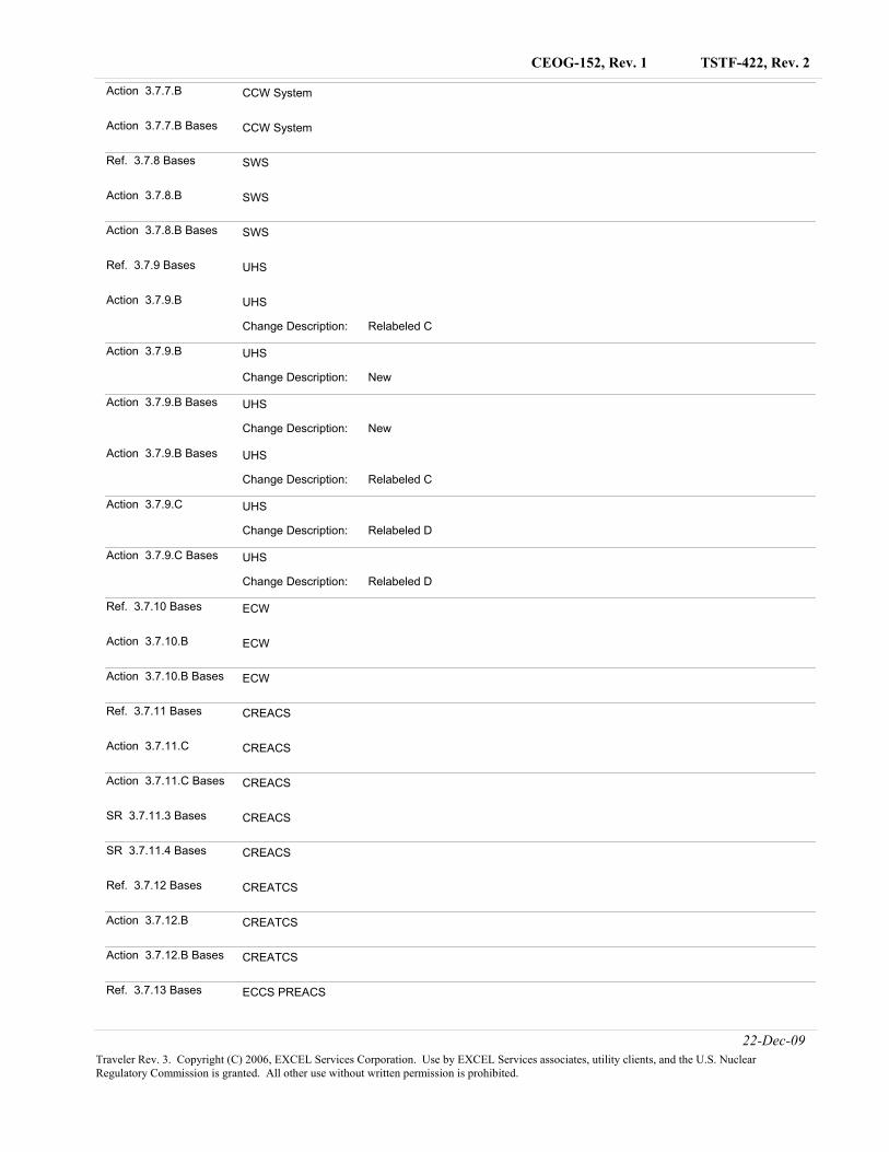
Ref. 3.7.7 Bases CCW System
22-Dec-09Traveler Rev. 3. Copyright (C) 2006, EXCEL Services Corporation. Use by EXCEL Services associates, utility clients, and the U.S. Nuclear Regulatory Commission is granted. All other use without written permission is prohibited.
TSTF-422, Rev. 2CEOG-152, Rev. 1
Action 3.7.7.B CCW System
Action 3.7.7.B Bases CCW System
Ref. 3.7.8 Bases SWS
Action 3.7.8.B SWS
Action 3.7.8.B Bases SWS
Ref. 3.7.9 Bases UHS
Action 3.7.9.B
Relabeled CChange Description:
UHS
Action 3.7.9.B
NewChange Description:
UHS
Action 3.7.9.B Bases
NewChange Description:
UHS
Action 3.7.9.B Bases
Relabeled CChange Description:
UHS
Action 3.7.9.C
Relabeled DChange Description:
UHS
Action 3.7.9.C Bases
Relabeled DChange Description:
UHS
Ref. 3.7.10 Bases ECW
Action 3.7.10.B ECW
Action 3.7.10.B Bases ECW
Ref. 3.7.11 Bases CREACS
Action 3.7.11.C CREACS
Action 3.7.11.C Bases CREACS
SR 3.7.11.3 Bases CREACS
SR 3.7.11.4 Bases CREACS
Ref. 3.7.12 Bases CREATCS
Action 3.7.12.B CREATCS
Action 3.7.12.B Bases CREATCS
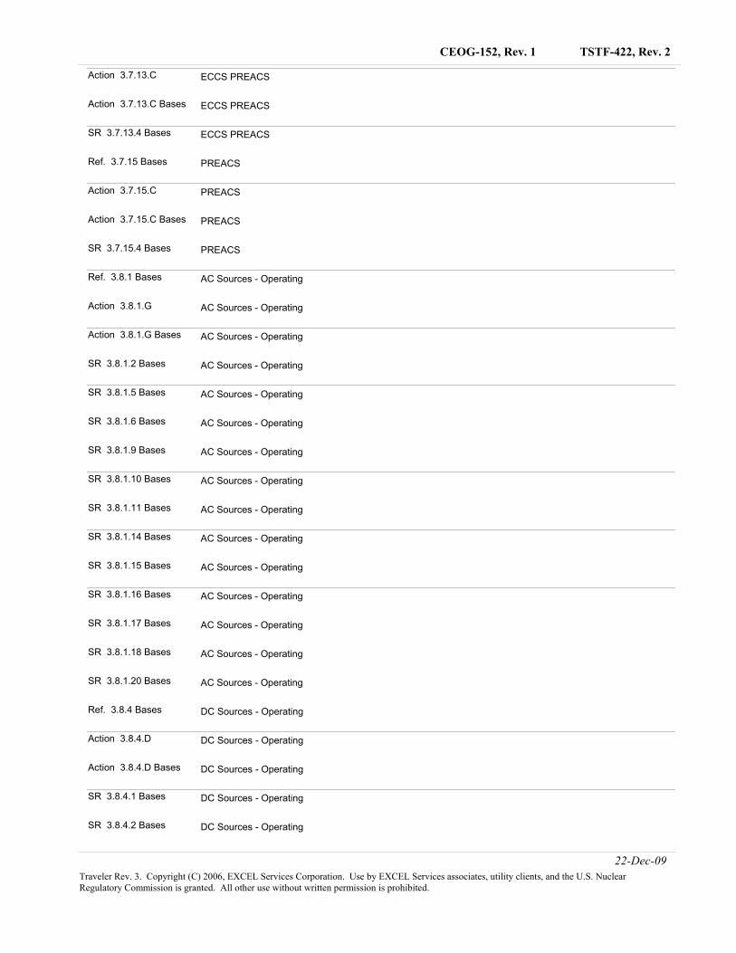
Ref. 3.7.13 Bases ECCS PREACS
22-Dec-09Traveler Rev. 3. Copyright (C) 2006, EXCEL Services Corporation. Use by EXCEL Services associates, utility clients, and the U.S. Nuclear Regulatory Commission is granted. All other use without written permission is prohibited.
TSTF-422, Rev. 2CEOG-152, Rev. 1
Action 3.7.13.C ECCS PREACS
Action 3.7.13.C Bases ECCS PREACS
SR 3.7.13.4 Bases ECCS PREACS
Ref. 3.7.15 Bases PREACS
Action 3.7.15.C PREACS
Action 3.7.15.C Bases PREACS
SR 3.7.15.4 Bases PREACS
Ref. 3.8.1 Bases AC Sources - Operating
Action 3.8.1.G AC Sources - Operating
Action 3.8.1.G Bases AC Sources - Operating
SR 3.8.1.2 Bases AC Sources - Operating
SR 3.8.1.5 Bases AC Sources - Operating
SR 3.8.1.6 Bases AC Sources - Operating
SR 3.8.1.9 Bases AC Sources - Operating
SR 3.8.1.10 Bases AC Sources - Operating
SR 3.8.1.11 Bases AC Sources - Operating
SR 3.8.1.14 Bases AC Sources - Operating
SR 3.8.1.15 Bases AC Sources - Operating
SR 3.8.1.16 Bases AC Sources - Operating
SR 3.8.1.17 Bases AC Sources - Operating
SR 3.8.1.18 Bases AC Sources - Operating
SR 3.8.1.20 Bases AC Sources - Operating
Ref. 3.8.4 Bases DC Sources - Operating
Action 3.8.4.D DC Sources - Operating
Action 3.8.4.D Bases DC Sources - Operating
SR 3.8.4.1 Bases DC Sources - Operating
SR 3.8.4.2 Bases DC Sources - Operating
22-Dec-09Traveler Rev. 3. Copyright (C) 2006, EXCEL Services Corporation. Use by EXCEL Services associates, utility clients, and the U.S. Nuclear Regulatory Commission is granted. All other use without written permission is prohibited.
TSTF-422, Rev. 2CEOG-152, Rev. 1
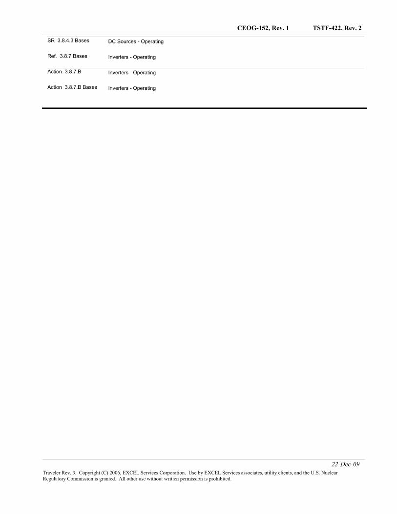
SR 3.8.4.3 Bases DC Sources - Operating
Ref. 3.8.7 Bases Inverters - Operating
Action 3.8.7.B Inverters - Operating
Action 3.8.7.B Bases Inverters - Operating
22-Dec-09Traveler Rev. 3. Copyright (C) 2006, EXCEL Services Corporation. Use by EXCEL Services associates, utility clients, and the U.S. Nuclear Regulatory Commission is granted. All other use without written permission is prohibited.
TSTF-422, Rev. 2
Attachment 1
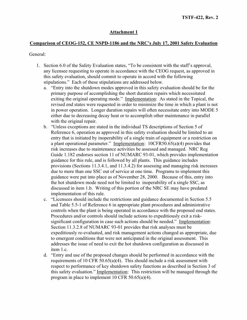
Comparison of CEOG-152, CE NSPD-1186 and the NRC’s July 17, 2001 Safety Evaluation General:
1. Section 6.0 of the Safety Evaluation states, “To be consistent with the staff’s approval, any licensee requesting to operate in accordance with the CEOG request, as approved in this safety evaluation, should commit to operate in accord with the following stipulations.” Each of these stipulations are addressed below. a. “Entry into the shutdown modes approved in this safety evaluation should be for the
primary purpose of accomplishing the short duration repairs which necessitated exiting the original operating mode.” Implementation: As stated in the Topical, the revised end states were requested in order to minimize the time in which a plant is not in power operation. Longer duration repairs will often necessitate entry into MODE 5 either due to decreasing decay heat or to accomplish other maintenance in parallel with the original repair.
b. “Unless exceptions are stated in the individual TS descriptions of Section 5 of Reference 6, operation as approved in this safety evaluation should be limited to an entry that is initiated by inoperability of a single train of equipment or a restriction on a plant operational parameter.” Implementation: 10CFR50.65(a)(4) provides that risk increases due to maintenance activities be assessed and managed. NRC Reg Guide 1.182 endorses section 11 of NUMARC 93-01, which provides implementation guidance for this rule, and is followed by all plants. This guidance includes provisions (Sections 11.3.4.1, and 11.3.4.2) for assessing and managing risk increases due to more than one SSC out of service at one time. Programs to implement this guidance were put into place as of November 28, 2000. Because of this, entry into the hot shutdown mode need not be limited to inoperability of a single SSC, as discussed in item 1.b. Writing of this portion of the NRC SE may have predated implementation of this rule.
c. “Licensees should include the restrictions and guidance documented in Section 5.5 and Table 5.5-1 of Reference 6 in appropriate plant procedures and administrative controls when the plant is being operated in accordance with the proposed end states. Procedures and/or controls should include actions to expeditiously exit a risk-significant configuration in case such actions should be needed.” Implementation: Section 11.3.2.8 of NUMARC 93-01 provides that risk analyses must be expeditiously re-evaluated, and risk management actions changed as appropriate, due to emergent conditions that were not anticipated in the original assessment. This addresses the issue of need to exit the hot shutdown configuration as discussed in item 1.c.
d. “Entry and use of the proposed changes should be performed in accordance with the requirements of 10 CFR 50.65(a)(4). This should include a risk assessment with respect to performance of key shutdown safety functions as described in Section 3 of this safety evaluation.” Implementation: This restriction will be managed through the program in place to implement 10 CFR 50.65(a)(4).
TSTF-422, Rev. 2
e. “The following conditions should be met unless exceptions are identified in Section 5 of this SE: i. Should SG cooling be lost while operating in Mode 4, there should be sufficient
water in the SGs and operational procedures shall exist to ensure that long-term SDC can be initiated.
ii. Uncontrolled loss-of-inventory events should be minimized by in-depth planning, maintaining the RCS at its nominal inventory and configuration control. In-depth event response capability, such as inventory addition, procedures, and training, should be provided.
iii. The LTOP and SDC are not aligned when the plant is operated in Mode 4 on SG cooling unless the plant is being transitioned to or from SDC operation. LTOP shall be operational when the SDC system is hydraulically connected to the RCS.”
Implementation: Section 11.3.6 of NUMARC 93-01 addresses shutdown key safety functions (including decay heat removal capability and inventory control). Sections 11.3.6.1 and 11.3.6.2 provide sufficient guidance to address the conditions raised regarding SG cooling versus SDC cooling, and unplanned loss of inventory events. LTOP will be aligned when required by technical specifications.
f. “The RCS pressure boundary should remain functional and, if isolated from the SDC system, should be capable of operating with pressure relief via the pressurizer safety valves.” Implementation: If the RCS pressure boundary is not functional, LCO 3.4.13 requires a plant shutdown. RCS pressure relief requirements are contained in LCO 3.4.10, Pressurizer Safety Valves, 3.4.11, Pressurizer PORVs, and 3.4.12, LTOP.
g. “The primary purpose of the CEOG request is to allow corrective maintenance in an operating mode consistent with safe operation after an AOT has been exceeded and, secondarily, to minimize the correction time so that the plant can be restored to power operation. Ordinarily, conditions addressed in this request, and in this SE, involve failures that result in a degraded plant condition. Consequently, with respect to additional licensee outage activities that could affect the safe conduct of operations and that are not directly required for correction of the failure(s) that caused the AOT to be exceeded, a licensee should: i. Perform a safety assessment in accordance with the maintenance rule prior to
undertaking such additional activities. ii. If conditions change so that the safety assessment is no longer valid, to suspend
all such additional activities via a process consistent with safety until such time as the assessment has been re-performed and is again valid.”
Implementation: Section 11.3.2.8 of NUMARC 93-01 addresses emergent conditions.
In summary, the stipulations contained in Section 6.0 of the SE are addressed by existing Technical Specifications, other regulatory initiatives, or the requirements of 10 CFR 50.65(a)(4). No restrictions in the Traveler are needed to address these stipulations.
2. In the majority of the individual TS evaluations in the Topical and the NRC’s SE, it was
stated that there was risk benefit to remaining in MODE 4 on SG heat removal by
TSTF-422, Rev. 2
averting the risks associated with the alignment of the SDC system. This information is not placed in the revised TS or Bases. LCO 3.4.6, RCS Loops – MODE 4, allows SG heat removal, SDC heat removal, or a combination of SG and SDC heat removal. The risks associated with transitioning from MODE 4 SG heat removal to MODE 4 SDC heat removal are required to be assessed and managed by 10 CFR 50.65(a)(4). Assessment and management of risks associated with SG versus SDC are covered by Section 11.3.6.1 of NUMARC 93-01. Therefore, it is unnecessary to repeat those requirements in the various TS and would be in conflict with LCO 3.4.6.
TSTF-422, Rev. 2
Evaluation of Each Specification # Spec Does Preferred End State
Apply to a Loss of LCO Safety Function?
Deviations from Topical or SE
1 3.1.9, Boration Systems – Operating
N/A This LCO does not exist in NUREG-1432. Therefore, no change is included in the Traveler.
2 3.3.4 (Analog), 3.3.5 (digital) ESFAS Instruments – RAS
N/A NUREG-1432 applicability for this function already stops at MODE 4. Therefore, no change is included in the Traveler.
3 3.3.5 (analog), 3.3.6 (digital) ESFAS Logic and Manual Trip
3.3.5 (analog) - No. 3.3.6 (digital) - Yes. ITS Condition E already allows a MODE 4 end state for two actuation logic channels inoperable. That is unaffected by this change.
No deviations.
4 3.3.8 (digital) CPIS
Yes. Note that the SE states that two CPIS channels are required to be OPERABLE but the NUREG only requires one. Section 5.5 of the SE states that without CPIS the operator must manually isolate containment purge and that this is acceptable. This represents the same condition as the NUREG ACTION for the one required CPIS channel inoperable.
The SE states, “The CEOG recommended that, when the CPIS is disabled, the operating staff should be alerted and operation of the containment mini-purge should be restricted. It further recommended consideration should be given to maintain availability of CIAS during the CPIS Mode 4 repair. The staff endorses these recommendations and licensees must commit to incorporate them into operating documentation.” The Topical, under Tier 2 Restrictions, states, “No tier 2 restrictions are necessary. However, when utilizing this option, it is recommended that when the CPIS is disabled, the operating staff should be alerted and operation of the containment mini-purge should be restricted. Consideration should be given to maintain availability of
TSTF-422, Rev. 2
# Spec Does Preferred End State Apply to a Loss of LCO
Safety Function?
Deviations from Topical or SE
CIAS during the CPIS Mode 4 repair.” The requirements and recommendations stated above will be managed through the program in place to implement 10 CFR 50.65(a)(4).
5 3.3.8 (analog), 3.3.9 (digital) CRIS
Yes. Only one channel of CRIS is required to be OPERABLE. Section 5.6 of the SE states that the entry condition is both channels of CRIS are inoperable and states that manual operator action is acceptable.
The NRC’s SE states, “The CEOG states that it would be prudent to minimize unavailability of SIAS and alternate shutdown panel and/or remote shutdown capabilities during Mode 4 operation with CRIS unavailable. The staff agrees. Licensees must commit to incorporate suitable guidance into their operational documentation to accomplish this.” The Topical, under Tier 2 Restrictions states, “None. It would be prudent to minimize unavailability of SIAS and alternate shutdown panel and/or remote shutdown capabilities during Mode 4 operation with CRIS unavailable.” The requirements and recommendations stated above will be managed through the program in place to implement 10 CFR 50.65(a)(4).
6 3.3.9 (analog), CVCS Isolation Signal
No. The NRC’s SE stated that there was risk benefit to remaining in MODE 4 on SG heat removal by averting the risks associated with the alignment of the SDC system. The Topical stated that when SDC entry may be avoided, transition risks associated with SDC alignment may be averted. The risks associated with
TSTF-422, Rev. 2
# Spec Does Preferred End State Apply to a Loss of LCO
Safety Function?
Deviations from Topical or SE
transitioning from MODE 4 SG heat removal to MODE 4 SDC heat removal are required to be assessed and managed by 10 CFR 50.65(a)(4) and do not need to be repeated in the TS.
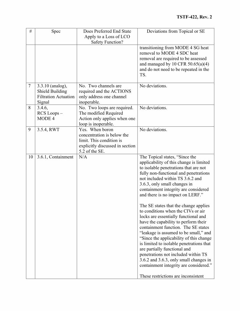
7 3.3.10 (analog), Shield Building Filtration Actuation Signal
No. Two channels are required and the ACTIONS only address one channel inoperable.
No deviations.
8 3.4.6, RCS Loops – MODE 4
No. Two loops are required. The modified Required Action only applies when one loop is inoperable.
No deviations.
9 3.5.4, RWT Yes. When boron concentration is below the limit. This condition is explicitly discussed in section 5.2 of the SE.
No deviations.
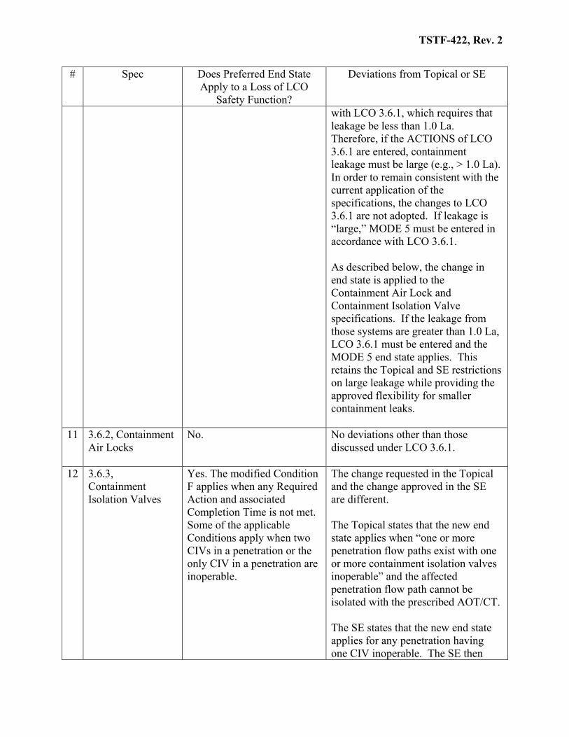
10 3.6.1, Containment N/A The Topical states, “Since the applicability of this change is limited to isolable penetrations that are not fully non-functional and penetrations not included within TS 3.6.2 and 3.6.3, only small changes in containment integrity are considered and there is no impact on LERF.” The SE states that the change applies to conditions when the CIVs or air locks are essentially functional and have the capability to perform their containment function. The SE states “leakage is assumed to be small,” and “Since the applicability of this change is limited to isolable penetrations that are partially functional and penetrations not included within TS 3.6.2 and 3.6.3, only small changes in containment integrity are considered.” These restrictions are inconsistent
TSTF-422, Rev. 2
# Spec Does Preferred End State Apply to a Loss of LCO
Safety Function?
Deviations from Topical or SE
with LCO 3.6.1, which requires that leakage be less than 1.0 La. Therefore, if the ACTIONS of LCO 3.6.1 are entered, containment leakage must be large (e.g., > 1.0 La). In order to remain consistent with the current application of the specifications, the changes to LCO 3.6.1 are not adopted. If leakage is “large,” MODE 5 must be entered in accordance with LCO 3.6.1. As described below, the change in end state is applied to the Containment Air Lock and Containment Isolation Valve specifications. If the leakage from those systems are greater than 1.0 La, LCO 3.6.1 must be entered and the MODE 5 end state applies. This retains the Topical and SE restrictions on large leakage while providing the approved flexibility for smaller containment leaks.
11 3.6.2, Containment Air Locks
No. No deviations other than those discussed under LCO 3.6.1.
12 3.6.3, Containment Isolation Valves
Yes. The modified Condition F applies when any Required Action and associated Completion Time is not met. Some of the applicable Conditions apply when two CIVs in a penetration or the only CIV in a penetration are inoperable.
The change requested in the Topical and the change approved in the SE are different. The Topical states that the new end state applies when “one or more penetration flow paths exist with one or more containment isolation valves inoperable” and the affected penetration flow path cannot be isolated with the prescribed AOT/CT. The SE states that the new end state applies for any penetration having one CIV inoperable. The SE then
TSTF-422, Rev. 2
# Spec Does Preferred End State Apply to a Loss of LCO
Safety Function?
Deviations from Topical or SE
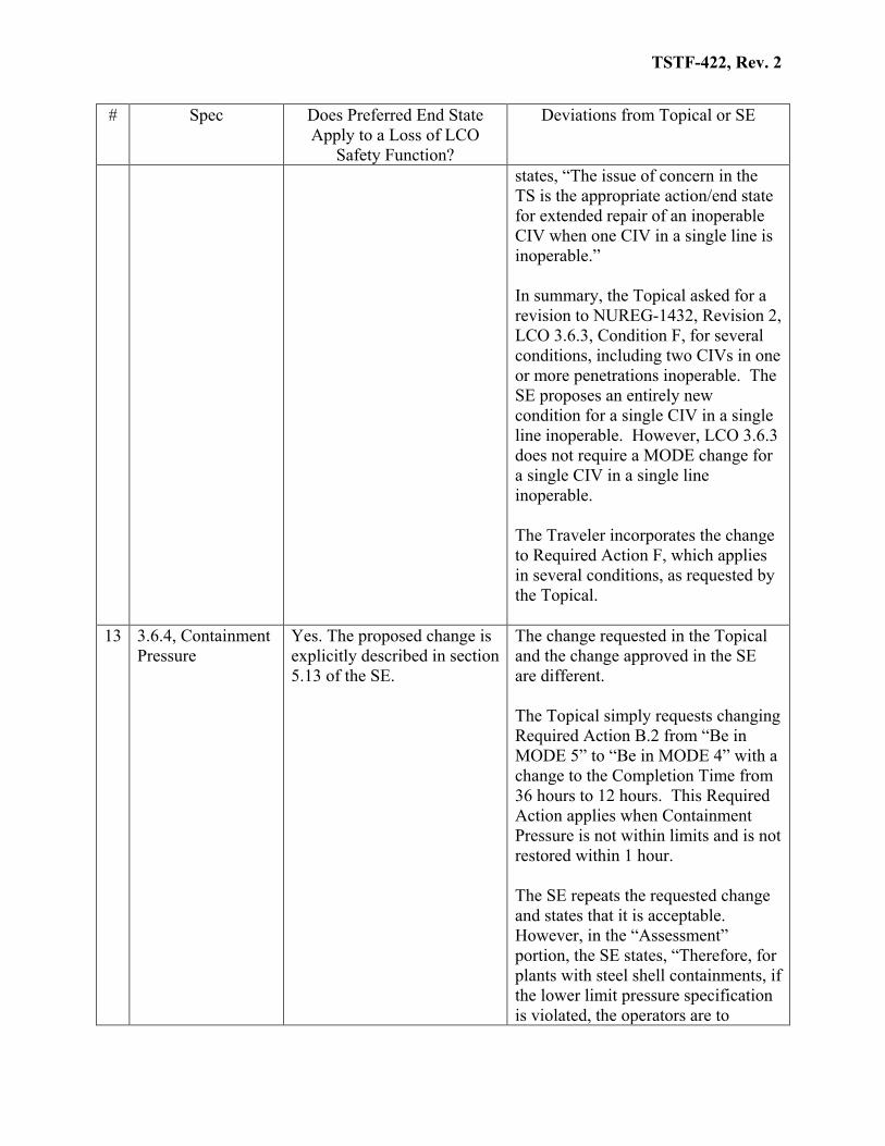
states, “The issue of concern in the TS is the appropriate action/end state for extended repair of an inoperable CIV when one CIV in a single line is inoperable.” In summary, the Topical asked for a revision to NUREG-1432, Revision 2, LCO 3.6.3, Condition F, for several conditions, including two CIVs in one or more penetrations inoperable. The SE proposes an entirely new condition for a single CIV in a single line inoperable. However, LCO 3.6.3 does not require a MODE change for a single CIV in a single line inoperable. The Traveler incorporates the change to Required Action F, which applies in several conditions, as requested by the Topical.
13 3.6.4, Containment Pressure
Yes. The proposed change is explicitly described in section 5.13 of the SE.
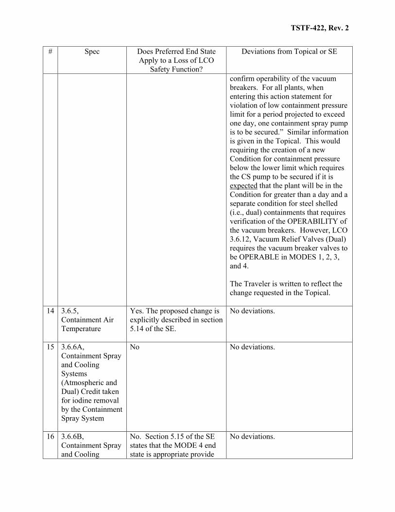
The change requested in the Topical and the change approved in the SE are different. The Topical simply requests changing Required Action B.2 from “Be in MODE 5” to “Be in MODE 4” with a change to the Completion Time from 36 hours to 12 hours. This Required Action applies when Containment Pressure is not within limits and is not restored within 1 hour. The SE repeats the requested change and states that it is acceptable. However, in the “Assessment” portion, the SE states, “Therefore, for plants with steel shell containments, if the lower limit pressure specification is violated, the operators are to
TSTF-422, Rev. 2
# Spec Does Preferred End State Apply to a Loss of LCO
Safety Function?
Deviations from Topical or SE
confirm operability of the vacuum breakers. For all plants, when entering this action statement for violation of low containment pressure limit for a period projected to exceed one day, one containment spray pump is to be secured.” Similar information is given in the Topical. This would requiring the creation of a new Condition for containment pressure below the lower limit which requires the CS pump to be secured if it is expected that the plant will be in the Condition for greater than a day and a separate condition for steel shelled (i.e., dual) containments that requires verification of the OPERABILITY of the vacuum breakers. However, LCO 3.6.12, Vacuum Relief Valves (Dual) requires the vacuum breaker valves to be OPERABLE in MODES 1, 2, 3, and 4. The Traveler is written to reflect the change requested in the Topical.
14 3.6.5, Containment Air Temperature
Yes. The proposed change is explicitly described in section 5.14 of the SE.
No deviations.
15 3.6.6A, Containment Spray and Cooling Systems (Atmospheric and Dual) Credit taken for iodine removal by the Containment Spray System
No No deviations.
16 3.6.6B, Containment Spray and Cooling
No. Section 5.15 of the SE states that the MODE 4 end state is appropriate provide
No deviations.
TSTF-422, Rev. 2
# Spec Does Preferred End State Apply to a Loss of LCO
Safety Function?
Deviations from Topical or SE
Systems (Atmospheric and Dual) Credit not taken for iodine removal by the Containment Spray System
one train of either containment spray or containment cooling is OPERABLE. The revised Condition F only applies if at least two trains are OPERABLE.
17 3.6.11, Shield Building (Dual)
Yes. The Conditions apply when the shield building is inoperable. The proposed change is consistent with the discussion in section 5.16 of the SE.
The SE makes the statement, “containment leakage is controlled via TS 3.6.1, and no major leak paths should be unisolable, there should be no contribution to an increased LERF.” The Topical, under Tier 2 Restrictions, states, “Shield building inoperability should not result in a “large” radiation release pathway (See TS 3.6.1).” As stated above, the Traveler retains the MODE 5 end state for LCO 3.6.1, consistent with the SE and Topical assumptions.
18 3.7.5, Auxiliary Feedwater
N/A The Topical addressed the LCO. However, the SE states that their July 3, 2001 letter CEOG withdrew this change as the ISTS already affords the proper end state when one or more AFW pumps are inoperable. Therefore, the Traveler does not contain a change to LCO 3.7.5.
19 3.7.7, Component Cooling Water System
No The SE and the Topical, under Tier 2 Restrictions, have additional conditions which modify the application of the new Condition. The Bases state, “A MODE 4 end state with the reactor coolant system on steam generator heat removal is preferred to the MODE 5 end state on shutdown cooling heat removal, provided CCW is available to the reactor coolant pumps.” The SE contains similar statements. The Topical states, “For conditions where
TSTF-422, Rev. 2
# Spec Does Preferred End State Apply to a Loss of LCO
Safety Function?
Deviations from Topical or SE
CCW flow is lost to the RCP seals, reactor shutdown is required and the RCS Loops operating TS is entered. Limited duration natural circulation operation is acceptable, but extended plant operation in the higher Mode 4 temperatures may degrade RCP seal elastomers. Mode 5 operation ensures adequately low RCS temperatures so that any RCP seal challenges would be avoided. Prior to entry into Mode 5 due to loss of CCW to RCP seals, the redundant CCW train should be confirmed to be operable and backup cooling water systems should be confirmed for emergency use. SG inventory should be retained to assure a diverse and redundant heat removal source if CCW should fail.” The Traveler modifies the TS to apply the MODE 4 end state and the Bases are modified to state that entry into MODE 5 should be considered if CCW flow is lost to the RCP seals.
20 3.7.8, Service Water System
No The Topical and the SE require entry into MODE 4 and reliance on the SGs for heat removal for the condition of one SWS loop inoperable. The Traveler does not incorporate the restriction to be using the SGs for heat removal. LCO 3.4.6, RCS Loops – MODE 4, requires two loops , consisting of any combination of RCS and SDC loops, to be OPERABLE and one loop to be in operation. Placing a restriction on the loops which can be used to satisfy LCO 3.4.6 in the SWS LCO is confusing and unnecessary. If an inoperable SWS loop results in a
TSTF-422, Rev. 2
# Spec Does Preferred End State Apply to a Loss of LCO
Safety Function?
Deviations from Topical or SE
inoperable SDC loop, that inoperable SDC loop cannot be used to meet the requirements of LCO 3.4.6. Restricting the utilization of an OPERABLE SDC loop supported by the remaining OPERABLE SWS loop is unnecessary and reduces redundancy and diversity of heat removal methods.
21 3.7.9, Ultimate Heat Sink
No. Revised Condition A Bases to reflect SE condition that one train is OPERABLE.
TSTF-330 added a Condition for UHS temperature greater than the LCO limit. This Condition was not considered in the Topical. Therefore, the MODE 5 end state was retained for this Condition and a new ACTION was added for the condition considered in the Topical.
22 3.7.10, Essential Chilled Water
No The Topical states under Tier 2 restrictions: “None. Reduced pressure operation in Mode 4 should be considered to reduce the potential of a LOCA without Emergency Chilled Water.” This recommendation will be managed through the program in place to implement 10 CFR 50.65(a)(4).
23 3.7.11, CREACS Yes. See discussion. Also note that changes to address control room habitability allow MODE 1 operation to continue with inoperable control room boundary.
Revision 2 of NUREG-1432 has two conditions which require entry into MODE 5 – one CREACS train inoperable and an inoperable control room boundary. The Topical states, “Regardless of the CREACS status, the risks of MODE 4 are lower (or equivalent) to the similar MODE 5 operating state.” The SE evaluation does not address the specific case of one CREACS train inoperable. Therefore, the MODE 4 end state was applied to both conditions.
TSTF-422, Rev. 2
# Spec Does Preferred End State Apply to a Loss of LCO
Safety Function?
Deviations from Topical or SE
The Topical states under Tier 2 restrictions: “Using CRMP ensures plant staff is aware of the system inoperability and that respiratory units and CR pressurization systems are available and operational and that leakage pathways are properly controlled. Also ensure availability of alternate shutdown panels and local shutdown stations.” This recommendation will be managed through the program in place to implement 10 CFR 50.65(a)(4).
24 3.7.12, CREATCS No The SE states, “for longer outages, licensees should ensure availability of the alternate shutdown panel or local plant shutdown and control capability.” This statement is in the Topical under Tier 2 Restrictions (after stating “None.”). This recommendation will be managed through the program in place to implement 10 CFR 50.65(a)(4).
25 3.7.13, ECCS PREACS
Yes. Because of changes from other TSTFs, the proposed end state also applies to two trains inoperable due to an inoperable boundary.
Revision 2 of NUREG-1432 has two Conditions which require entry into MODE 5 – one ECCS PREACS train inoperable and two ECCS PREACS trains inoperable due to inoperable ECCS pump room boundary. The Topical states, “Regardless of the ECCS PREACS status, the risk of MODE 4 are lower (or equivalent) to the similar MODE 5 operating state.” In order to adopt the NUREG-1432 condition for an inoperable ECCS pump room boundary, the licensee must commit to preplanned compensatory measures. Therefore, the MODE 4 end state was applied to both conditions.
TSTF-422, Rev. 2
# Spec Does Preferred End State Apply to a Loss of LCO
Safety Function?
Deviations from Topical or SE
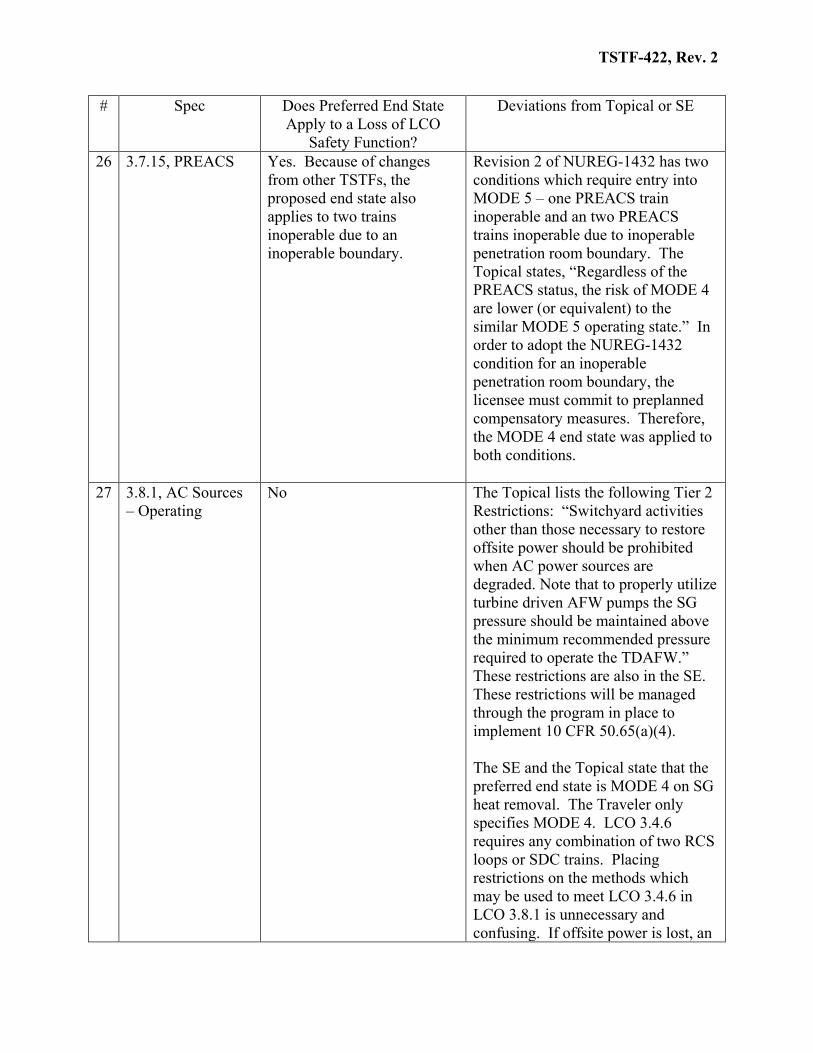
26 3.7.15, PREACS Yes. Because of changes from other TSTFs, the proposed end state also applies to two trains inoperable due to an inoperable boundary.
Revision 2 of NUREG-1432 has two conditions which require entry into MODE 5 – one PREACS train inoperable and an two PREACS trains inoperable due to inoperable penetration room boundary. The Topical states, “Regardless of the PREACS status, the risk of MODE 4 are lower (or equivalent) to the similar MODE 5 operating state.” In order to adopt the NUREG-1432 condition for an inoperable penetration room boundary, the licensee must commit to preplanned compensatory measures. Therefore, the MODE 4 end state was applied to both conditions.
27 3.8.1, AC Sources – Operating
No The Topical lists the following Tier 2 Restrictions: “Switchyard activities other than those necessary to restore offsite power should be prohibited when AC power sources are degraded. Note that to properly utilize turbine driven AFW pumps the SG pressure should be maintained above the minimum recommended pressure required to operate the TDAFW.” These restrictions are also in the SE. These restrictions will be managed through the program in place to implement 10 CFR 50.65(a)(4). The SE and the Topical state that the preferred end state is MODE 4 on SG heat removal. The Traveler only specifies MODE 4. LCO 3.4.6 requires any combination of two RCS loops or SDC trains. Placing restrictions on the methods which may be used to meet LCO 3.4.6 in LCO 3.8.1 is unnecessary and confusing. If offsite power is lost, an
TSTF-422, Rev. 2
# Spec Does Preferred End State Apply to a Loss of LCO
Safety Function?
Deviations from Topical or SE
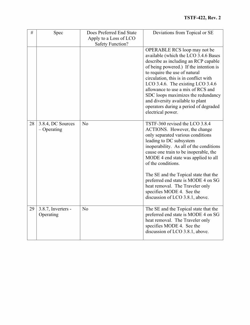
OPERABLE RCS loop may not be available (which the LCO 3.4.6 Bases describe as including an RCP capable of being powered.) If the intention is to require the use of natural circulation, this is in conflict with LCO 3.4.6. The existing LCO 3.4.6 allowance to use a mix of RCS and SDC loops maximizes the redundancy and diversity available to plant operators during a period of degraded electrical power.
28 3.8.4, DC Sources – Operating
No TSTF-360 revised the LCO 3.8.4 ACTIONS. However, the change only separated various conditions leading to DC subsystem inoperability. As all of the conditions cause one train to be inoperable, the MODE 4 end state was applied to all of the conditions. The SE and the Topical state that the preferred end state is MODE 4 on SG heat removal. The Traveler only specifies MODE 4. See the discussion of LCO 3.8.1, above.
29 3.8.7, Inverters - Operating
No The SE and the Topical state that the preferred end state is MODE 4 on SG heat removal. The Traveler only specifies MODE 4. See the discussion of LCO 3.8.1, above.
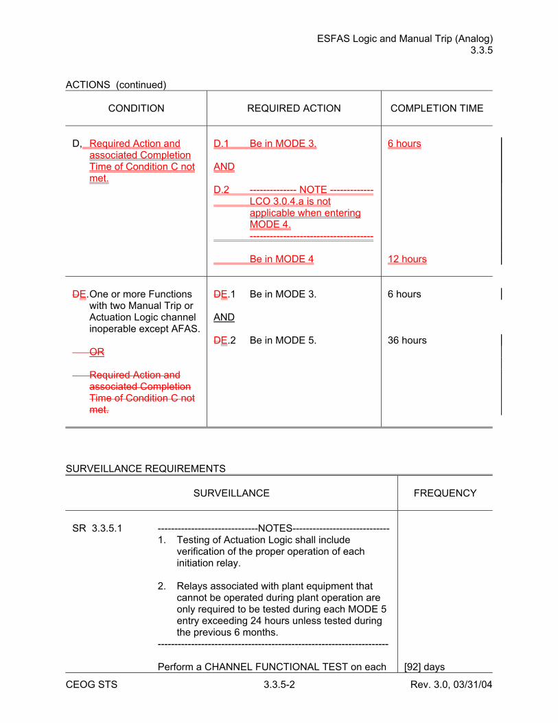
ESFAS Logic and Manual Trip (Analog) 3.3.5
CEOG STS 3.3.5-2 Rev. 3.0, 03/31/04
ACTIONS (continued)
CONDITION
REQUIRED ACTION
COMPLETION TIME
D, Required Action and
associated Completion Time of Condition C not met.
D.1 Be in MODE 3. AND D.2 -------------- NOTE ------------- LCO 3.0.4.a is not
applicable when entering MODE 4.
------------------------------------- Be in MODE 4
6 hours 12 hours
DE. One or more Functions
with two Manual Trip or Actuation Logic channel inoperable except AFAS.
OR Required Action and
associated Completion Time of Condition C not met.
DE.1 Be in MODE 3. AND DE.2 Be in MODE 5.
6 hours 36 hours
SURVEILLANCE REQUIREMENTS
SURVEILLANCE
FREQUENCY
SR 3.3.5.1 ------------------------------NOTES----------------------------- 1. Testing of Actuation Logic shall include
verification of the proper operation of each initiation relay.
2. Relays associated with plant equipment that
cannot be operated during plant operation are only required to be tested during each MODE 5 entry exceeding 24 hours unless tested during the previous 6 months.
--------------------------------------------------------------------- Perform a CHANNEL FUNCTIONAL TEST on each
[92] days
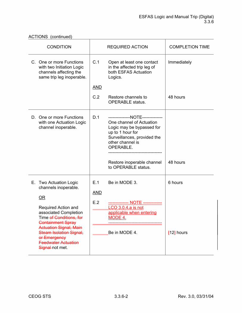
ESFAS Logic and Manual Trip (Digital) 3.3.6
CEOG STS 3.3.6-2 Rev. 3.0, 03/31/04
ACTIONS (continued)
CONDITION
REQUIRED ACTION
COMPLETION TIME
C. One or more Functions
with two Initiation Logic channels affecting the same trip leg inoperable.
C.1 Open at least one contact
in the affected trip leg of both ESFAS Actuation Logics.
AND C.2 Restore channels to
OPERABLE status.
Immediately 48 hours
D. One or more Functions
with one Actuation Logic channel inoperable.
D.1 ---------------NOTE-------------- One channel of Actuation
Logic may be bypassed for up to 1 hour for Surveillances, provided the other channel is OPERABLE.
------------------------------------- Restore inoperable channel
to OPERABLE status.
48 hours
E. Two Actuation Logic
channels inoperable. OR Required Action and
associated Completion Time of Conditions, for Containment Spray Actuation Signal, Main Steam Isolation Signal, or Emergency Feedwater Actuation Signal not met.
E.1 Be in MODE 3. AND E.2 -------------- NOTE ------------- LCO 3.0.4.a is not
applicable when entering MODE 4.
------------------------------------- Be in MODE 4.
6 hours [12] hours
ESFAS Logic and Manual Trip (Digital) 3.3.6
CEOG STS 3.3.6-3 Rev. 3.0, 03/31/04
ACTIONS (continued)
CONDITION
REQUIRED ACTION
COMPLETION TIME
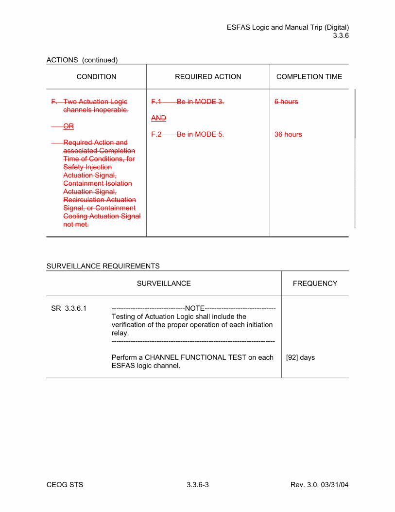
F. Two Actuation Logic
channels inoperable. OR Required Action and
associated Completion Time of Conditions, for Safety Injection Actuation Signal, Containment Isolation Actuation Signal, Recirculation Actuation Signal, or Containment Cooling Actuation Signal not met.
F.1 Be in MODE 3. AND F.2 Be in MODE 5.
6 hours 36 hours
SURVEILLANCE REQUIREMENTS
SURVEILLANCE
FREQUENCY
SR 3.3.6.1 -------------------------------NOTE------------------------------ Testing of Actuation Logic shall include the
verification of the proper operation of each initiation relay.
--------------------------------------------------------------------- Perform a CHANNEL FUNCTIONAL TEST on each
ESFAS logic channel.
[92] days

CRIS (Analog) 3.3.8
CEOG STS 3.3.8-1 Rev. 3.0, 03/31/04
3.3 INSTRUMENTATION 3.3.8 Control Room Isolation Signal (CRIS) (Analog) LCO 3.3.8 One CRIS channel shall be OPERABLE. APPLICABILITY: MODES 1, 2, 3, 4, [5, and 6], During movement of [recently] irradiated fuel assemblies. ACTIONS
CONDITION
REQUIRED ACTION
COMPLETION TIME
A. CRIS Manual Trip,
Actuation Logic, or [one or more required channels of particulate/iodine or gaseous] radiation monitors inoperable in MODE 1, 2, 3, or 4.
A.1 --------------NOTE-------------- Place Control Room
Emergency Air Cleanup System (CREACS) in toxic gas protection mode if automatic transfer to toxic gas protection mode inoperable.
------------------------------------- Place one CREACS train in
emergency radiation protection mode.
1 hour
B. Required Action and
associated Completion Time of Condition A not met.
B.1 Be in MODE 3. AND B.2 -------------- NOTE ------------- LCO 3.0.4.a is not
applicable when entering MODE 4.
------------------------------------- Be in MODE 54.
6 hours 36 12 hours
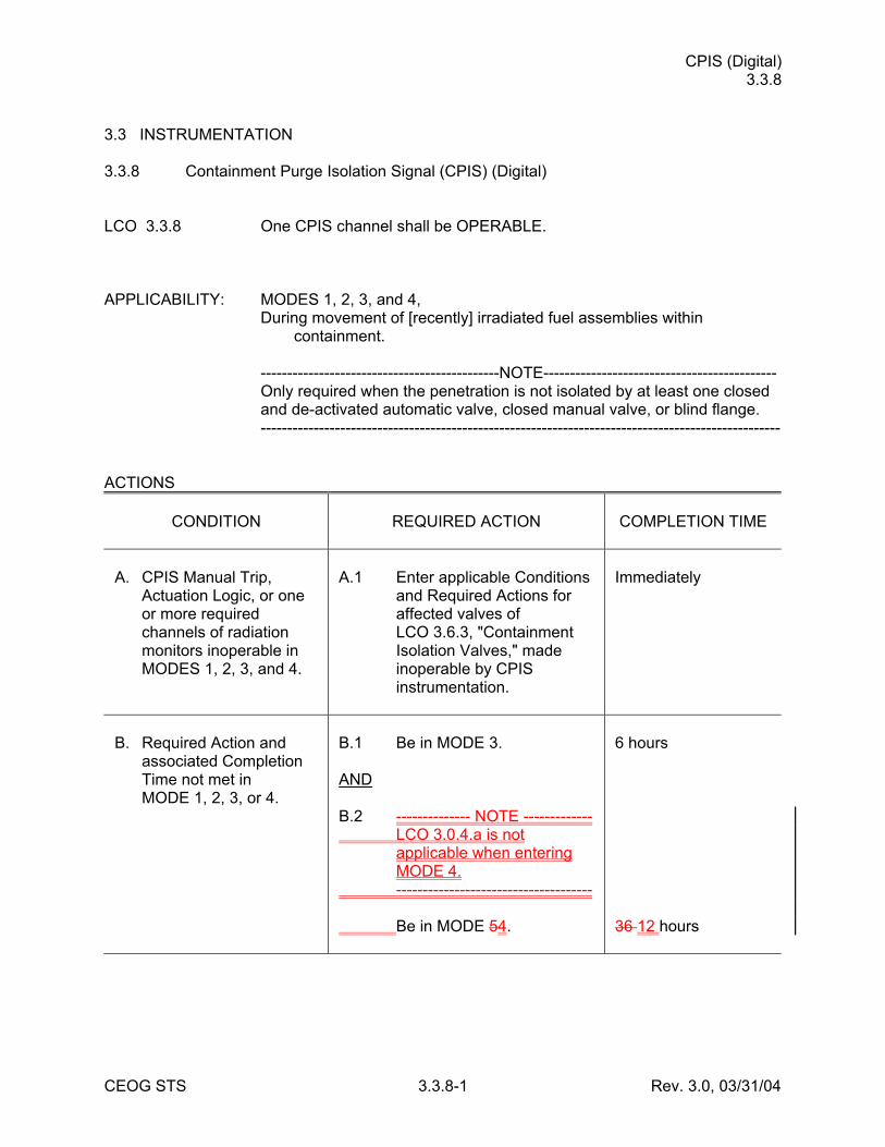
CPIS (Digital) 3.3.8
CEOG STS 3.3.8-1 Rev. 3.0, 03/31/04
3.3 INSTRUMENTATION 3.3.8 Containment Purge Isolation Signal (CPIS) (Digital) LCO 3.3.8 One CPIS channel shall be OPERABLE. APPLICABILITY: MODES 1, 2, 3, and 4, During movement of [recently] irradiated fuel assemblies within
containment. ---------------------------------------------NOTE-------------------------------------------- Only required when the penetration is not isolated by at least one closed
and de-activated automatic valve, closed manual valve, or blind flange. -------------------------------------------------------------------------------------------------- ACTIONS
CONDITION
REQUIRED ACTION
COMPLETION TIME
A. CPIS Manual Trip,
Actuation Logic, or one or more required channels of radiation monitors inoperable in MODES 1, 2, 3, and 4.
A.1 Enter applicable Conditions
and Required Actions for affected valves of LCO 3.6.3, "Containment Isolation Valves," made inoperable by CPIS instrumentation.
Immediately
B. Required Action and
associated Completion Time not met in MODE 1, 2, 3, or 4.
B.1 Be in MODE 3. AND B.2 -------------- NOTE ------------- LCO 3.0.4.a is not
applicable when entering MODE 4.
------------------------------------- Be in MODE 54.
6 hours 36 12 hours
CVCS Isolation Signal (Analog) 3.3.9
CEOG STS 3.3.9-2 Rev. 3.0, 03/31/04
ACTIONS (continued)
CONDITION
REQUIRED ACTION
COMPLETION TIME
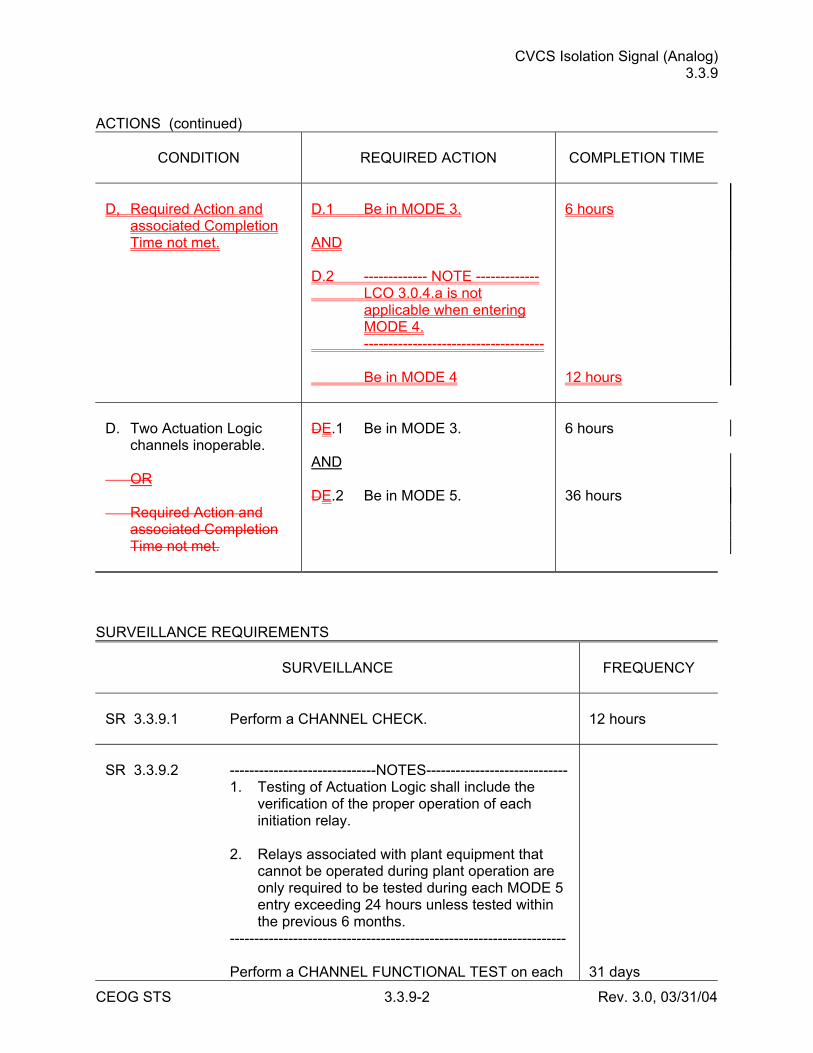
D, Required Action and
associated Completion Time not met.
D.1 Be in MODE 3. AND D.2 ------------- NOTE ------------- LCO 3.0.4.a is not
applicable when entering MODE 4.
------------------------------------- Be in MODE 4
6 hours 12 hours
D. Two Actuation Logic
channels inoperable. OR Required Action and
associated Completion Time not met.
DE.1 Be in MODE 3. AND DE.2 Be in MODE 5.
6 hours 36 hours
SURVEILLANCE REQUIREMENTS
SURVEILLANCE
FREQUENCY
SR 3.3.9.1 Perform a CHANNEL CHECK.
12 hours
SR 3.3.9.2 ------------------------------NOTES----------------------------- 1. Testing of Actuation Logic shall include the
verification of the proper operation of each initiation relay.
2. Relays associated with plant equipment that
cannot be operated during plant operation are only required to be tested during each MODE 5 entry exceeding 24 hours unless tested within the previous 6 months.
--------------------------------------------------------------------- Perform a CHANNEL FUNCTIONAL TEST on each
31 days
CRIS (Digital) 3.3.9
CEOG STS 3.3.9-1 Rev. 3.0, 03/31/04
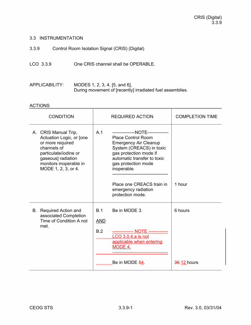
3.3 INSTRUMENTATION 3.3.9 Control Room Isolation Signal (CRIS) (Digital) LCO 3.3.9 One CRIS channel shall be OPERABLE. APPLICABILITY: MODES 1, 2, 3, 4, [5, and 6], During movement of [recently] irradiated fuel assemblies. ACTIONS
CONDITION
REQUIRED ACTION
COMPLETION TIME
A. CRIS Manual Trip,
Actuation Logic, or [one or more required channels of particulate/iodine or gaseous] radiation monitors inoperable in MODE 1, 2, 3, or 4.
A.1 ---------------NOTE-------------- Place Control Room
Emergency Air Cleanup System (CREACS) in toxic gas protection mode if automatic transfer to toxic gas protection mode inoperable.
------------------------------------- Place one CREACS train in
emergency radiation protection mode.
1 hour
B. Required Action and
associated Completion Time of Condition A not met.
B.1 Be in MODE 3. AND B.2 -------------- NOTE ------------- LCO 3.0.4.a is not
applicable when entering MODE 4.
------------------------------------- Be in MODE 54.
6 hours 36 12 hours
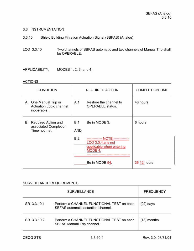
SBFAS (Analog) 3.3.10
CEOG STS 3.3.10-1 Rev. 3.0, 03/31/04
3.3 INSTRUMENTATION 3.3.10 Shield Building Filtration Actuation Signal (SBFAS) (Analog) LCO 3.3.10 Two channels of SBFAS automatic and two channels of Manual Trip shall
be OPERABLE. APPLICABILITY: MODES 1, 2, 3, and 4. ACTIONS
CONDITION
REQUIRED ACTION
COMPLETION TIME
A. One Manual Trip or
Actuation Logic channel inoperable.
A.1 Restore the channel to
OPERABLE status.
48 hours
B. Required Action and
associated Completion Time not met.
B.1 Be in MODE 3. AND B.2 ------------- NOTE ------------- LCO 3.0.4.a is not
applicable when entering MODE 4.
------------------------------------- Be in MODE 54.
6 hours 36 12 hours
SURVEILLANCE REQUIREMENTS
SURVEILLANCE
FREQUENCY
SR 3.3.10.1 Perform a CHANNEL FUNCTIONAL TEST on each
SBFAS automatic actuation channel.
[92] days
SR 3.3.10.2 Perform a CHANNEL FUNCTIONAL TEST on each
SBFAS Manual Trip channel.
[18] months
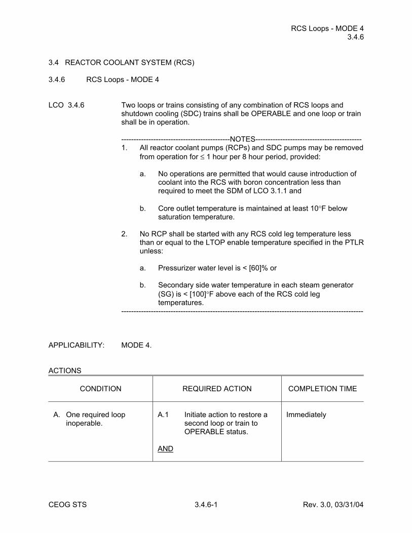
RCS Loops - MODE 4 3.4.6
CEOG STS 3.4.6-1 Rev. 3.0, 03/31/04
3.4 REACTOR COOLANT SYSTEM (RCS) 3.4.6 RCS Loops - MODE 4 LCO 3.4.6 Two loops or trains consisting of any combination of RCS loops and
shutdown cooling (SDC) trains shall be OPERABLE and one loop or train shall be in operation.
--------------------------------------------NOTES------------------------------------------- 1. All reactor coolant pumps (RCPs) and SDC pumps may be removed
from operation for ≤ 1 hour per 8 hour period, provided: a. No operations are permitted that would cause introduction of
coolant into the RCS with boron concentration less than required to meet the SDM of LCO 3.1.1 and
b. Core outlet temperature is maintained at least 10°F below
saturation temperature. 2. No RCP shall be started with any RCS cold leg temperature less
than or equal to the LTOP enable temperature specified in the PTLR unless:
a. Pressurizer water level is < [60]% or b. Secondary side water temperature in each steam generator
(SG) is < [100]°F above each of the RCS cold leg temperatures.
-------------------------------------------------------------------------------------------------- APPLICABILITY: MODE 4. ACTIONS
CONDITION
REQUIRED ACTION
COMPLETION TIME
A. One required loop
inoperable.
A.1 Initiate action to restore a
second loop or train to OPERABLE status.
AND
Immediately
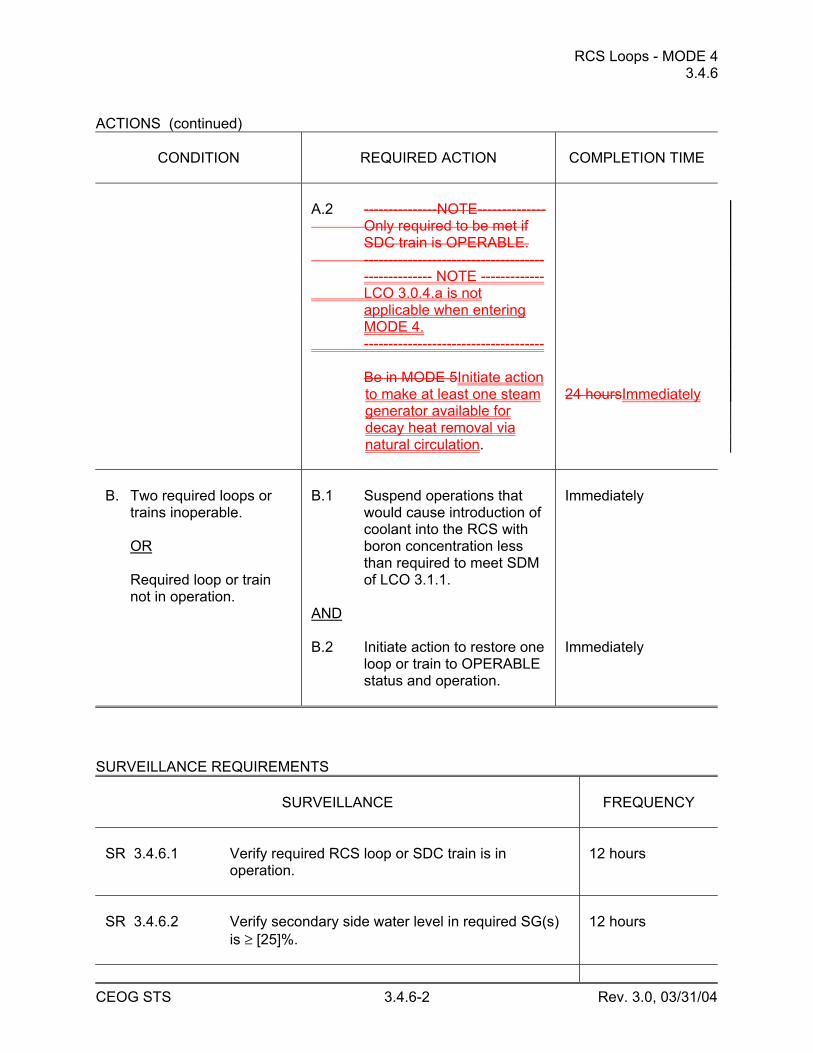
RCS Loops - MODE 4 3.4.6
CEOG STS 3.4.6-2 Rev. 3.0, 03/31/04
ACTIONS (continued)
CONDITION
REQUIRED ACTION
COMPLETION TIME
A.2 ---------------NOTE-------------- Only required to be met if
SDC train is OPERABLE. -------------------------------------
-------------- NOTE ------------- LCO 3.0.4.a is not
applicable when entering MODE 4.
------------------------------------- Be in MODE 5Initiate action
to make at least one steam generator available for decay heat removal via natural circulation.
24 hoursImmediately
B. Two required loops or
trains inoperable. OR Required loop or train
not in operation.
B.1 Suspend operations that
would cause introduction of coolant into the RCS with boron concentration less than required to meet SDM of LCO 3.1.1.
AND B.2 Initiate action to restore one
loop or train to OPERABLE status and operation.
Immediately Immediately
SURVEILLANCE REQUIREMENTS
SURVEILLANCE
FREQUENCY
SR 3.4.6.1 Verify required RCS loop or SDC train is in
operation.
12 hours
SR 3.4.6.2 Verify secondary side water level in required SG(s)
is ≥ [25]%.
12 hours
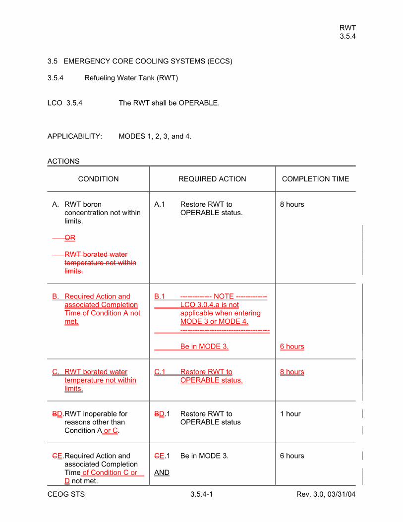
RWT 3.5.4
CEOG STS 3.5.4-1 Rev. 3.0, 03/31/04
3.5 EMERGENCY CORE COOLING SYSTEMS (ECCS) 3.5.4 Refueling Water Tank (RWT) LCO 3.5.4 The RWT shall be OPERABLE. APPLICABILITY: MODES 1, 2, 3, and 4. ACTIONS
CONDITION
REQUIRED ACTION
COMPLETION TIME
A. RWT boron
concentration not within limits.
OR RWT borated water
temperature not within limits.
A.1 Restore RWT to
OPERABLE status.
8 hours
B. Required Action and
associated Completion Time of Condition A not met.
B.1 ------------- NOTE ------------- LCO 3.0.4.a is not
applicable when entering MODE 3 or MODE 4.
------------------------------------- Be in MODE 3.
6 hours
C. RWT borated water
temperature not within limits.
C.1 Restore RWT to
OPERABLE status.
8 hours
BD. RWT inoperable for
reasons other than Condition A or C.
BD.1 Restore RWT to
OPERABLE status
1 hour
CE. Required Action and
associated Completion Time of Condition C or D not met.
CE.1 Be in MODE 3. AND
6 hours
RWT 3.5.4
CEOG STS 3.5.4-2 Rev. 3.0, 03/31/04
CONDITION
REQUIRED ACTION
COMPLETION TIME
CE.2 Be in MODE 5.
36 hours
Containment Air Locks (Atmospheric and Dual) 3.6.2
CEOG STS 3.6.2-3 Rev. 3.0, 03/31/04
ACTIONS (continued)
CONDITION
REQUIRED ACTION
COMPLETION TIME
B.2 Lock an OPERABLE door
closed in the affected air lock.
AND B.3 ---------------NOTE-------------- Air lock doors in high
radiation areas may be verified locked closed by administrative means.
------------------------------------- Verify an OPERABLE door
is locked closed in the affected air lock.
24 hours Once per 31 days
C. One or more
containment air locks inoperable for reasons other than Condition A or B.
C.1 Initiate action to evaluate
overall containment leakage rate per LCO 3.6.1.
AND C.2 Verify a door is closed in
the affected air lock. AND C.3 Restore air lock to
OPERABLE status.
Immediately 1 hour 24 hours
D. Required Action and
associated Completion Time not met.
D.1 Be in MODE 3. AND D.2 -------------- NOTE ------------- LCO 3.0.4.a is not
applicable when entering MODE 4.
------------------------------------- Be in MODE 54.
6 hours 36 12 hours
Containment Isolation Valves (Atmospheric and Dual) 3.6.3
CEOG STS 3.6.3-6 Rev. 3.1, 12/01/05
ACTIONS (continued)
CONDITION
REQUIRED ACTION
COMPLETION TIME
F.3 Perform SR 3.6.3.6 for the
resilient seal purge valves closed to comply with Required Action F.1.
Once per [ ] days ]
G. Required Action and
associated Completion Time not met.
G.1 Be in MODE 3. AND G.2 -------------- NOTE ------------- LCO 3.0.4.a is not
applicable when entering MODE 4.
------------------------------------- Be in MODE 54.
6 hours 36 12 hours
SURVEILLANCE REQUIREMENTS
SURVEILLANCE
FREQUENCY
SR 3.6.3.1 [ Verify each [42] inch purge valve is sealed closed
except for one purge valve in a penetration flow path while in Condition E of this LCO.
31 days ]
SR 3.6.3.2 Verify each [8] inch purge valve is closed except
when the [8] inch purge valves are open for pressure control, ALARA or air quality considerations for personnel entry, or for Surveillances that require the valves to be open.
31 days
SR 3.6.3.3 -------------------------------NOTE------------------------------ Valves and blind flanges in high radiation areas may
be verified by use of administrative means. --------------------------------------------------------------------- Verify each containment isolation manual valve and
blind flange that is located outside containment and not locked, sealed, or otherwise secured and is
31 days
Containment Pressure (Atmospheric and Dual) 3.6.4
CEOG STS 3.6.4-1 Rev. 3.0, 03/31/04
3.6 CONTAINMENT SYSTEMS 3.6.4 Containment Pressure (Atmospheric and Dual) LCO 3.6.4 Containment pressure shall be [Dual: > 14.375 psia and < 27 inches
water gauge] [or] [Atmospheric: ≥ -0.3 psig and ≤ +1.5 psig]. APPLICABILITY: MODES 1, 2, 3, and 4. ACTIONS
CONDITION
REQUIRED ACTION
COMPLETION TIME
A. Containment pressure
not within limits.
A.1 Restore containment
pressure to within limits.
1 hour
B. Required Action and
associated Completion Time not met.
B.1 Be in MODE 3. AND B.2 -------------- NOTE ------------- LCO 3.0.4.a is not
applicable when entering MODE 4.
------------------------------------- Be in MODE 54.
6 hours 36 12 hours
SURVEILLANCE REQUIREMENTS
SURVEILLANCE
FREQUENCY
SR 3.6.4.1 Verify containment pressure is within limits.
12 hours
Containment Air Temperature (Atmospheric and Dual) 3.6.5
CEOG STS 3.6.5-1 Rev. 3.0, 03/31/04
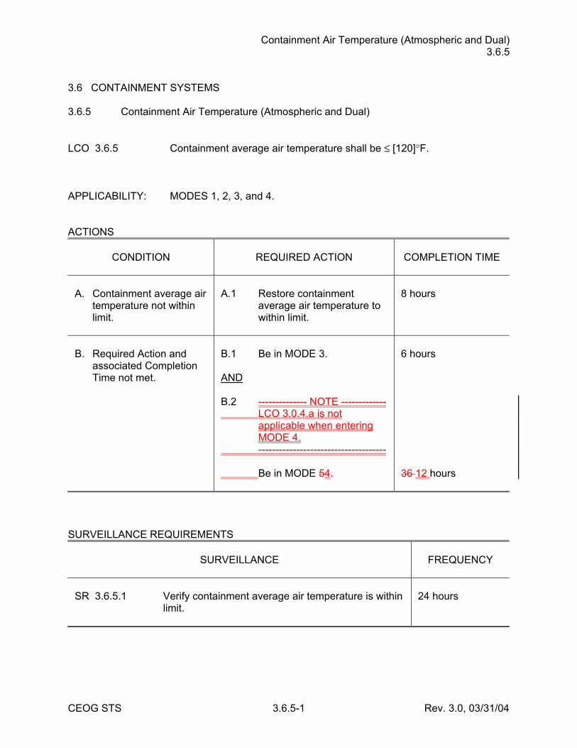
3.6 CONTAINMENT SYSTEMS 3.6.5 Containment Air Temperature (Atmospheric and Dual) LCO 3.6.5 Containment average air temperature shall be ≤ [120]°F. APPLICABILITY: MODES 1, 2, 3, and 4. ACTIONS
CONDITION
REQUIRED ACTION
COMPLETION TIME
A. Containment average air
temperature not within limit.
A.1 Restore containment
average air temperature to within limit.
8 hours
B. Required Action and
associated Completion Time not met.
B.1 Be in MODE 3. AND B.2 -------------- NOTE ------------- LCO 3.0.4.a is not
applicable when entering MODE 4.
------------------------------------- Be in MODE 54.
6 hours 36 12 hours
SURVEILLANCE REQUIREMENTS
SURVEILLANCE
FREQUENCY
SR 3.6.5.1 Verify containment average air temperature is within
limit.
24 hours
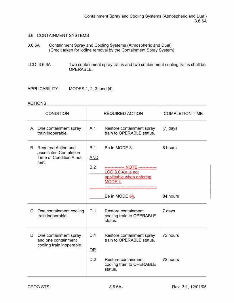
Containment Spray and Cooling Systems (Atmospheric and Dual) 3.6.6A
CEOG STS 3.6.6A-1 Rev. 3.1, 12/01/05
3.6 CONTAINMENT SYSTEMS 3.6.6A Containment Spray and Cooling Systems (Atmospheric and Dual) (Credit taken for iodine removal by the Containment Spray System) LCO 3.6.6A Two containment spray trains and two containment cooling trains shall be
OPERABLE. APPLICABILITY: MODES 1, 2, 3, and [4]. ACTIONS
CONDITION
REQUIRED ACTION
COMPLETION TIME
A. One containment spray
train inoperable.
A.1 Restore containment spray
train to OPERABLE status.
[7] days
B. Required Action and
associated Completion Time of Condition A not met.
B.1 Be in MODE 3. AND B.2 -------------- NOTE ------------- LCO 3.0.4.a is not
applicable when entering MODE 4.
------------------------------------- Be in MODE 54.
6 hours 84 hours
C. One containment cooling
train inoperable.
C.1 Restore containment
cooling train to OPERABLE status.
7 days
D. One containment spray
and one containment cooling train inoperable.
D.1 Restore containment spray
train to OPERABLE status. OR D.2 Restore containment
cooling train to OPERABLE status.
72 hours 72 hours
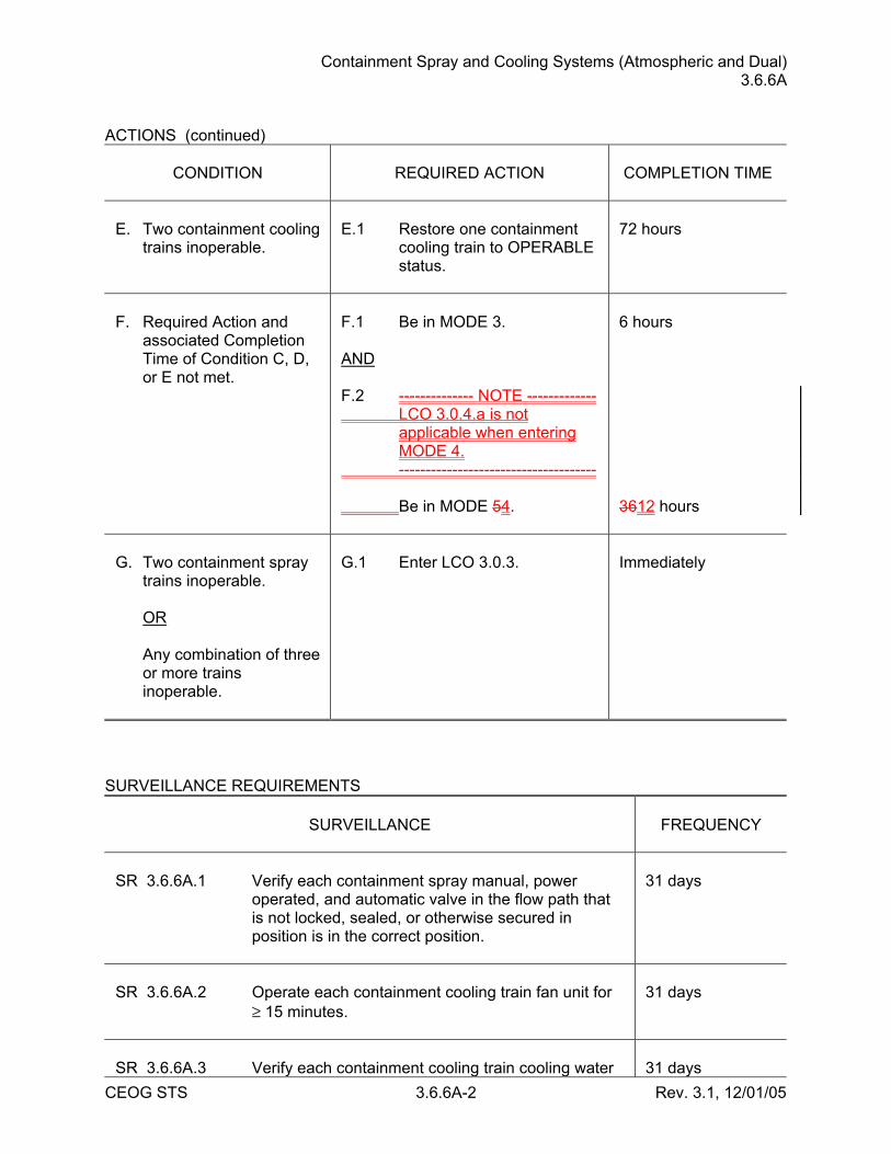
Containment Spray and Cooling Systems (Atmospheric and Dual) 3.6.6A
CEOG STS 3.6.6A-2 Rev. 3.1, 12/01/05
ACTIONS (continued)
CONDITION
REQUIRED ACTION
COMPLETION TIME
E. Two containment cooling
trains inoperable.
E.1 Restore one containment
cooling train to OPERABLE status.
72 hours
F. Required Action and
associated Completion Time of Condition C, D, or E not met.
F.1 Be in MODE 3. AND F.2 -------------- NOTE ------------- LCO 3.0.4.a is not
applicable when entering MODE 4.
------------------------------------- Be in MODE 54.
6 hours 3612 hours
G. Two containment spray
trains inoperable. OR Any combination of three
or more trains inoperable.
G.1 Enter LCO 3.0.3.
Immediately
SURVEILLANCE REQUIREMENTS
SURVEILLANCE
FREQUENCY
SR 3.6.6A.1 Verify each containment spray manual, power
operated, and automatic valve in the flow path that is not locked, sealed, or otherwise secured in position is in the correct position.
31 days
SR 3.6.6A.2 Operate each containment cooling train fan unit for
≥ 15 minutes.
31 days
SR 3.6.6A.3 Verify each containment cooling train cooling water
31 days
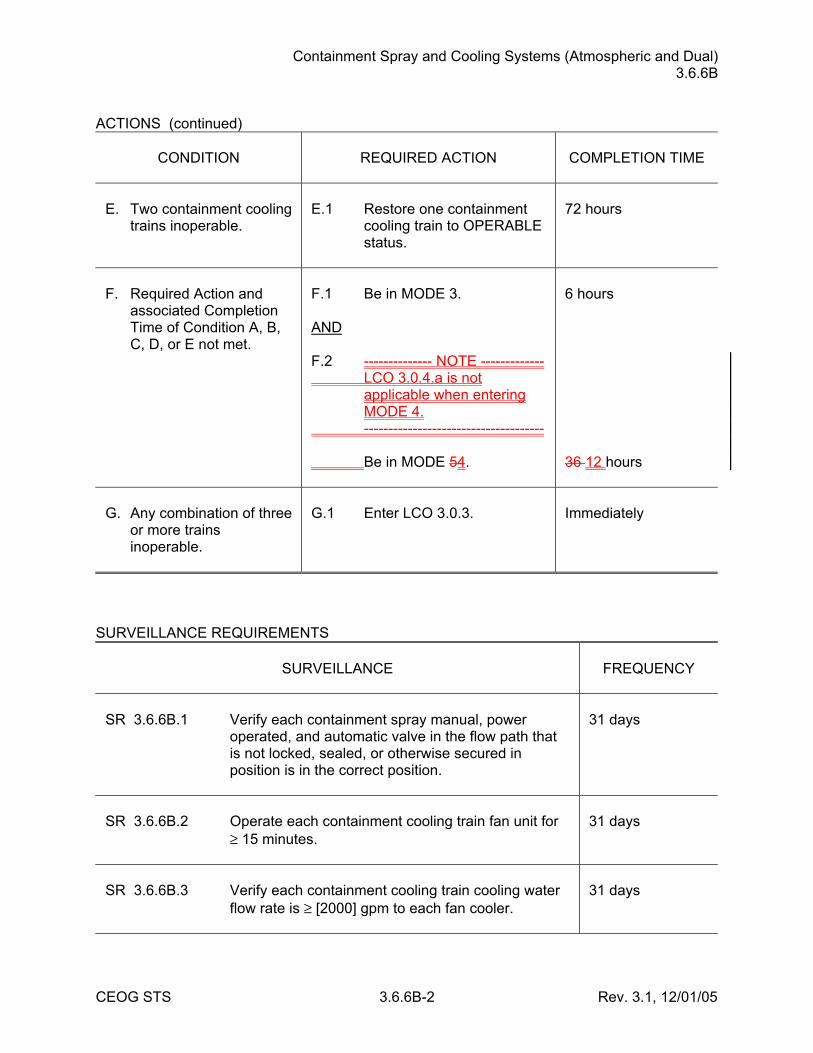
Containment Spray and Cooling Systems (Atmospheric and Dual) 3.6.6B
CEOG STS 3.6.6B-2 Rev. 3.1, 12/01/05
ACTIONS (continued)
CONDITION
REQUIRED ACTION
COMPLETION TIME
E. Two containment cooling
trains inoperable.
E.1 Restore one containment
cooling train to OPERABLE status.
72 hours
F. Required Action and
associated Completion Time of Condition A, B, C, D, or E not met.
F.1 Be in MODE 3. AND F.2 -------------- NOTE ------------- LCO 3.0.4.a is not
applicable when entering MODE 4.
------------------------------------- Be in MODE 54.
6 hours 36 12 hours
G. Any combination of three
or more trains inoperable.
G.1 Enter LCO 3.0.3.
Immediately
SURVEILLANCE REQUIREMENTS
SURVEILLANCE
FREQUENCY
SR 3.6.6B.1 Verify each containment spray manual, power
operated, and automatic valve in the flow path that is not locked, sealed, or otherwise secured in position is in the correct position.
31 days
SR 3.6.6B.2 Operate each containment cooling train fan unit for
≥ 15 minutes.
31 days
SR 3.6.6B.3 Verify each containment cooling train cooling water
flow rate is ≥ [2000] gpm to each fan cooler.
31 days
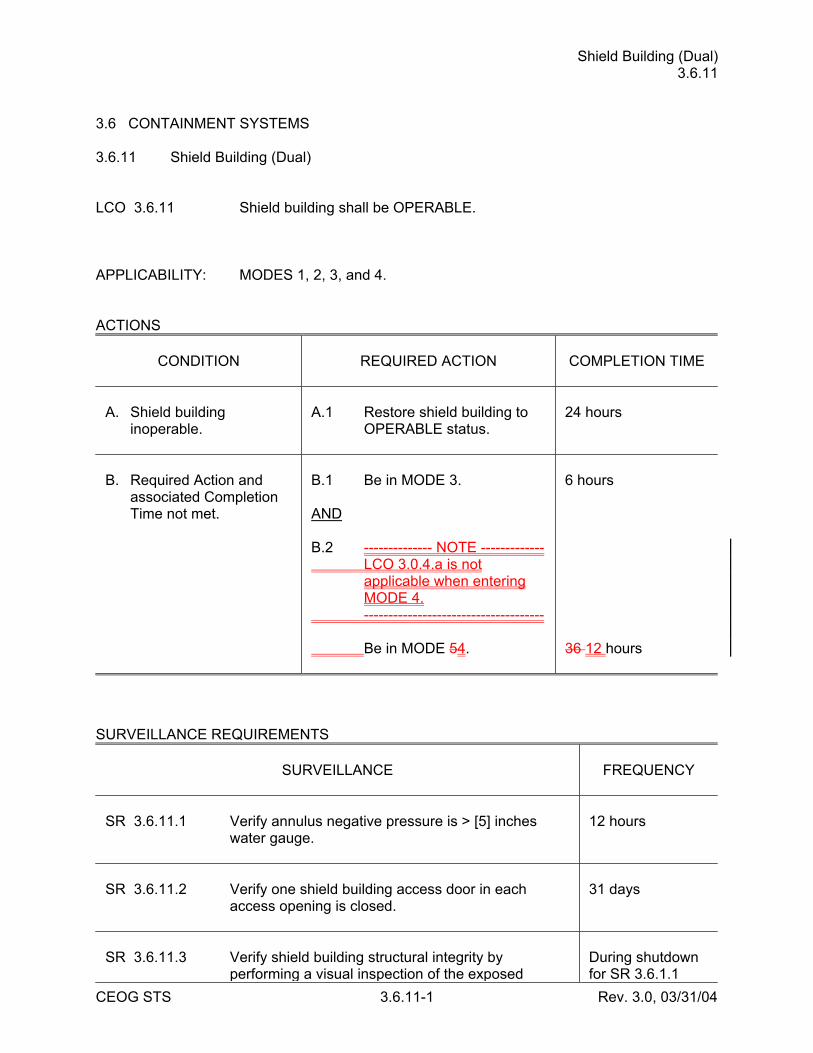
Shield Building (Dual) 3.6.11
CEOG STS 3.6.11-1 Rev. 3.0, 03/31/04
3.6 CONTAINMENT SYSTEMS 3.6.11 Shield Building (Dual) LCO 3.6.11 Shield building shall be OPERABLE. APPLICABILITY: MODES 1, 2, 3, and 4. ACTIONS
CONDITION
REQUIRED ACTION
COMPLETION TIME
A. Shield building
inoperable.
A.1 Restore shield building to
OPERABLE status.
24 hours
B. Required Action and
associated Completion Time not met.
B.1 Be in MODE 3. AND B.2 -------------- NOTE ------------- LCO 3.0.4.a is not
applicable when entering MODE 4.
------------------------------------- Be in MODE 54.
6 hours 36 12 hours
SURVEILLANCE REQUIREMENTS
SURVEILLANCE
FREQUENCY
SR 3.6.11.1 Verify annulus negative pressure is > [5] inches
water gauge.
12 hours
SR 3.6.11.2 Verify one shield building access door in each
access opening is closed.
31 days
SR 3.6.11.3 Verify shield building structural integrity by
performing a visual inspection of the exposed
During shutdown for SR 3.6.1.1
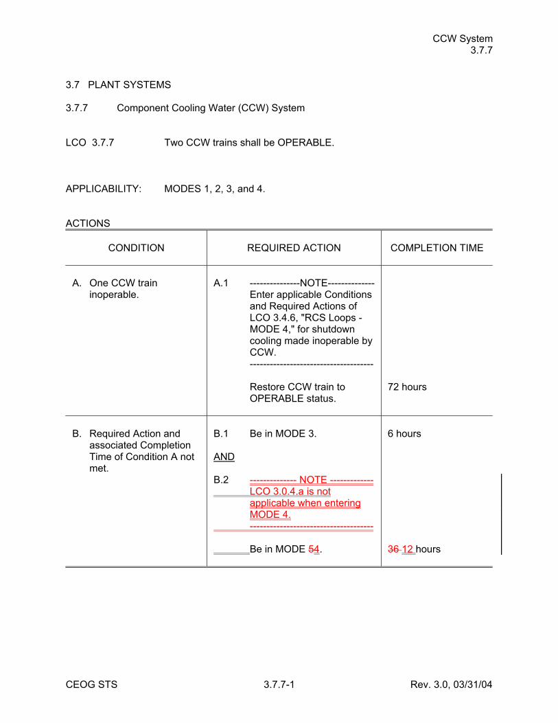
CCW System 3.7.7
CEOG STS 3.7.7-1 Rev. 3.0, 03/31/04
3.7 PLANT SYSTEMS 3.7.7 Component Cooling Water (CCW) System LCO 3.7.7 Two CCW trains shall be OPERABLE. APPLICABILITY: MODES 1, 2, 3, and 4. ACTIONS
CONDITION
REQUIRED ACTION
COMPLETION TIME
A. One CCW train
inoperable.
A.1 ---------------NOTE-------------- Enter applicable Conditions
and Required Actions of LCO 3.4.6, "RCS Loops - MODE 4," for shutdown cooling made inoperable by CCW.
------------------------------------- Restore CCW train to
OPERABLE status.
72 hours
B. Required Action and
associated Completion Time of Condition A not met.
B.1 Be in MODE 3. AND B.2 -------------- NOTE ------------- LCO 3.0.4.a is not
applicable when entering MODE 4.
------------------------------------- Be in MODE 54.
6 hours 36 12 hours
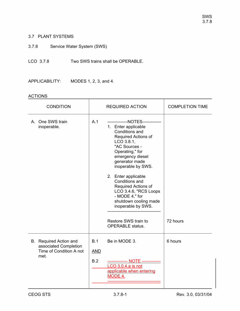
SWS 3.7.8
CEOG STS 3.7.8-1 Rev. 3.0, 03/31/04
3.7 PLANT SYSTEMS 3.7.8 Service Water System (SWS) LCO 3.7.8 Two SWS trains shall be OPERABLE. APPLICABILITY: MODES 1, 2, 3, and 4. ACTIONS
CONDITION
REQUIRED ACTION
COMPLETION TIME
A. One SWS train
inoperable.
A.1 --------------NOTES------------- 1. Enter applicable
Conditions and Required Actions of LCO 3.8.1, "AC Sources - Operating," for emergency diesel generator made inoperable by SWS.
2. Enter applicable
Conditions and Required Actions of LCO 3.4.6, "RCS Loops - MODE 4," for shutdown cooling made inoperable by SWS.
------------------------------------- Restore SWS train to
OPERABLE status.
72 hours
B. Required Action and
associated Completion Time of Condition A not met.
B.1 Be in MODE 3. AND B.2 -------------- NOTE ------------- LCO 3.0.4.a is not
applicable when entering MODE 4.
-------------------------------------
6 hours
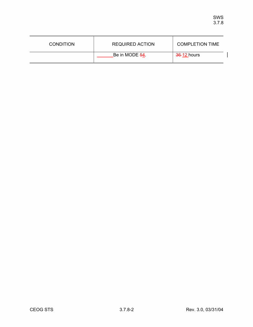
SWS 3.7.8
CEOG STS 3.7.8-2 Rev. 3.0, 03/31/04
CONDITION
REQUIRED ACTION
COMPLETION TIME
Be in MODE 54.
36 12 hours
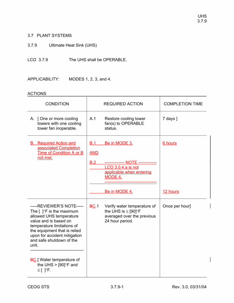
UHS 3.7.9
CEOG STS 3.7.9-1 Rev. 3.0, 03/31/04
3.7 PLANT SYSTEMS 3.7.9 Ultimate Heat Sink (UHS) LCO 3.7.9 The UHS shall be OPERABLE. APPLICABILITY: MODES 1, 2, 3, and 4. ACTIONS
CONDITION
REQUIRED ACTION
COMPLETION TIME
A. [ One or more cooling
towers with one cooling tower fan inoperable.
A.1 Restore cooling tower
fan(s) to OPERABLE status.
7 days ]
B. Required Action and
associated Completion Time of Condition A or B not met.
B.1 Be in MODE 3. AND B.2 -------------- NOTE ------------- LCO 3.0.4.a is not
applicable when entering MODE 4.
------------------------------------- Be in MODE 4.
6 hours 12 hours
-----REVIEWER’S NOTE----- The [ ]°F is the maximum allowed UHS temperature value and is based on temperature limitations of the equipment that is relied upon for accident mitigation and safe shutdown of the unit. -------------------------------------- BC. [ Water temperature of
the UHS > [90]°F and ≤ [ ]°F.
BC.1 Verify water temperature of
the UHS is ≤ [90]°F averaged over the previous 24 hour period.
Once per hour]
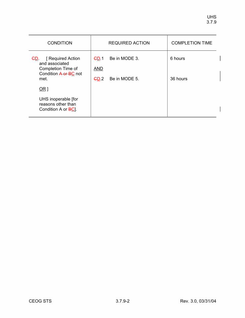
UHS 3.7.9
CEOG STS 3.7.9-2 Rev. 3.0, 03/31/04
CONDITION
REQUIRED ACTION
COMPLETION TIME
CD. [ Required Action
and associated Completion Time of Condition A or BC not met.
OR ] UHS inoperable [for
reasons other than Condition A or BC].
CD.1 Be in MODE 3. AND CD.2 Be in MODE 5.
6 hours 36 hours
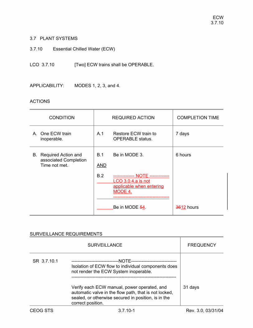
ECW 3.7.10
CEOG STS 3.7.10-1 Rev. 3.0, 03/31/04
3.7 PLANT SYSTEMS 3.7.10 Essential Chilled Water (ECW) LCO 3.7.10 [Two] ECW trains shall be OPERABLE. APPLICABILITY: MODES 1, 2, 3, and 4. ACTIONS
CONDITION
REQUIRED ACTION
COMPLETION TIME
A. One ECW train
inoperable.
A.1 Restore ECW train to
OPERABLE status.
7 days
B. Required Action and
associated Completion Time not met.
B.1 Be in MODE 3. AND B.2 -------------- NOTE ------------- LCO 3.0.4.a is not
applicable when entering MODE 4.
------------------------------------- Be in MODE 54.
6 hours 3612 hours
SURVEILLANCE REQUIREMENTS
SURVEILLANCE
FREQUENCY
SR 3.7.10.1 -------------------------------NOTE------------------------------ Isolation of ECW flow to individual components does
not render the ECW System inoperable. --------------------------------------------------------------------- Verify each ECW manual, power operated, and
automatic valve in the flow path, that is not locked, sealed, or otherwise secured in position, is in the correct position.
31 days
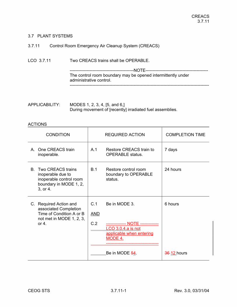
CREACS 3.7.11
CEOG STS 3.7.11-1 Rev. 3.0, 03/31/04
3.7 PLANT SYSTEMS 3.7.11 Control Room Emergency Air Cleanup System (CREACS) LCO 3.7.11 Two CREACS trains shall be OPERABLE. ---------------------------------------------NOTE-------------------------------------------- The control room boundary may be opened intermittently under
administrative control. -------------------------------------------------------------------------------------------------- APPLICABILITY: MODES 1, 2, 3, 4, [5, and 6,] During movement of [recently] irradiated fuel assemblies. ACTIONS
CONDITION
REQUIRED ACTION
COMPLETION TIME
A. One CREACS train
inoperable.
A.1 Restore CREACS train to
OPERABLE status.
7 days
B. Two CREACS trains
inoperable due to inoperable control room boundary in MODE 1, 2, 3, or 4.
B.1 Restore control room
boundary to OPERABLE status.
24 hours
C. Required Action and
associated Completion Time of Condition A or B not met in MODE 1, 2, 3, or 4.
C.1 Be in MODE 3. AND C.2 -------------- NOTE ------------- LCO 3.0.4.a is not
applicable when entering MODE 4.
------------------------------------- Be in MODE 54.
6 hours 36 12 hours
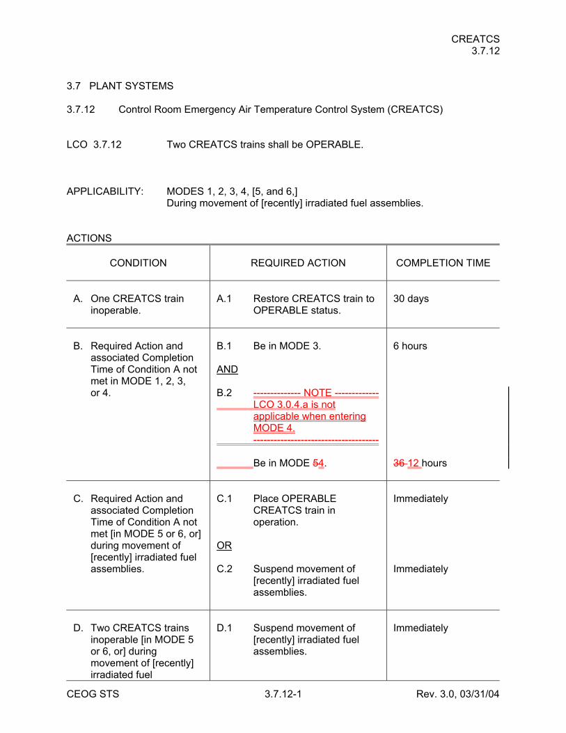
CREATCS 3.7.12
CEOG STS 3.7.12-1 Rev. 3.0, 03/31/04
3.7 PLANT SYSTEMS 3.7.12 Control Room Emergency Air Temperature Control System (CREATCS) LCO 3.7.12 Two CREATCS trains shall be OPERABLE. APPLICABILITY: MODES 1, 2, 3, 4, [5, and 6,] During movement of [recently] irradiated fuel assemblies. ACTIONS
CONDITION
REQUIRED ACTION
COMPLETION TIME
A. One CREATCS train
inoperable.
A.1 Restore CREATCS train to
OPERABLE status.
30 days
B. Required Action and
associated Completion Time of Condition A not met in MODE 1, 2, 3, or 4.
B.1 Be in MODE 3. AND B.2 -------------- NOTE ------------- LCO 3.0.4.a is not
applicable when entering MODE 4.
------------------------------------- Be in MODE 54.
6 hours 36 12 hours
C. Required Action and
associated Completion Time of Condition A not met [in MODE 5 or 6, or] during movement of [recently] irradiated fuel assemblies.
C.1 Place OPERABLE
CREATCS train in operation.
OR C.2 Suspend movement of
[recently] irradiated fuel assemblies.
Immediately Immediately
D. Two CREATCS trains
inoperable [in MODE 5 or 6, or] during movement of [recently] irradiated fuel
D.1 Suspend movement of
[recently] irradiated fuel assemblies.
Immediately
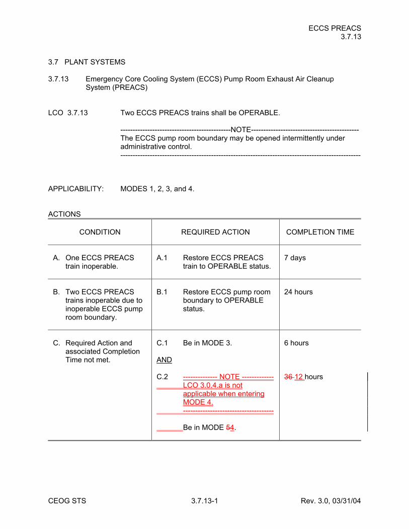
ECCS PREACS 3.7.13
CEOG STS 3.7.13-1 Rev. 3.0, 03/31/04
3.7 PLANT SYSTEMS 3.7.13 Emergency Core Cooling System (ECCS) Pump Room Exhaust Air Cleanup
System (PREACS) LCO 3.7.13 Two ECCS PREACS trains shall be OPERABLE. ---------------------------------------------NOTE-------------------------------------------- The ECCS pump room boundary may be opened intermittently under
administrative control. -------------------------------------------------------------------------------------------------- APPLICABILITY: MODES 1, 2, 3, and 4. ACTIONS
CONDITION
REQUIRED ACTION
COMPLETION TIME
A. One ECCS PREACS
train inoperable.
A.1 Restore ECCS PREACS
train to OPERABLE status.
7 days
B. Two ECCS PREACS
trains inoperable due to inoperable ECCS pump room boundary.
B.1 Restore ECCS pump room
boundary to OPERABLE status.
24 hours
C. Required Action and
associated Completion Time not met.
C.1 Be in MODE 3. AND C.2 -------------- NOTE ------------- LCO 3.0.4.a is not
applicable when entering MODE 4.
------------------------------------- Be in MODE 54.
6 hours 36 12 hours
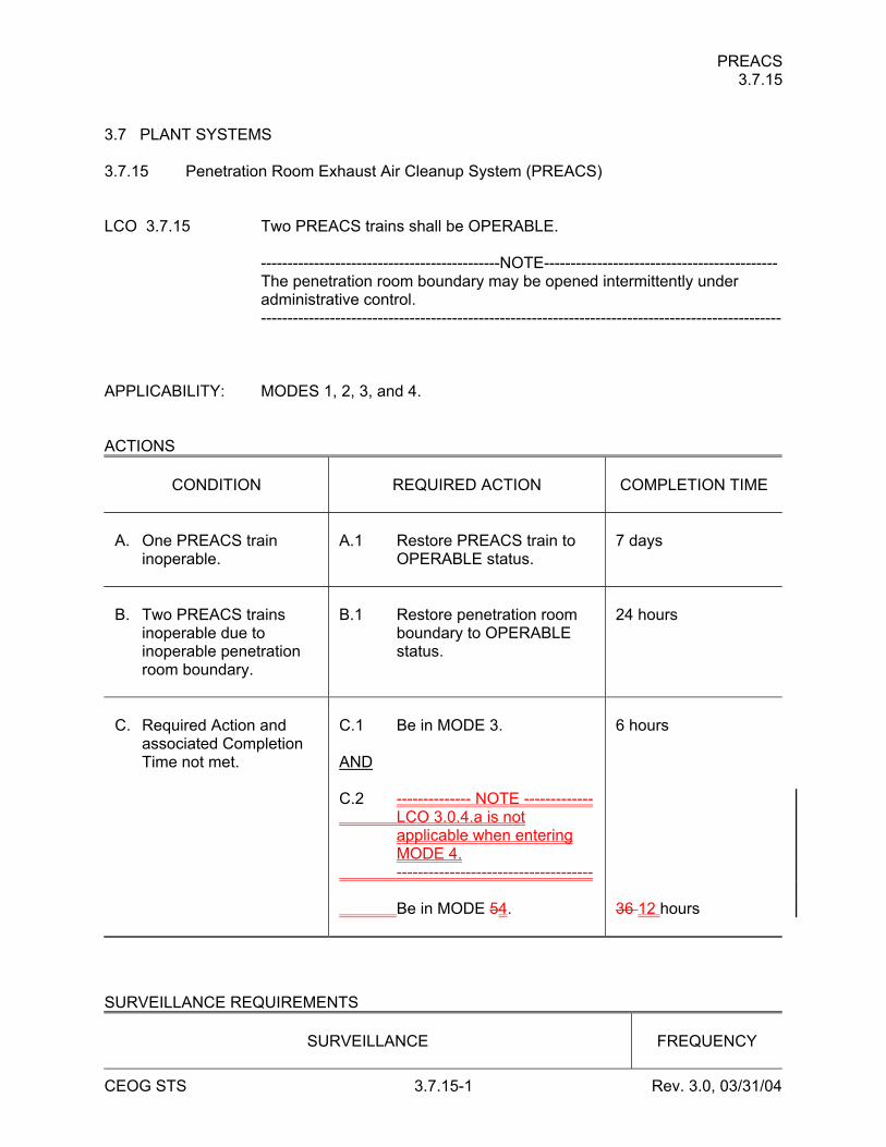
PREACS 3.7.15
CEOG STS 3.7.15-1 Rev. 3.0, 03/31/04
3.7 PLANT SYSTEMS 3.7.15 Penetration Room Exhaust Air Cleanup System (PREACS) LCO 3.7.15 Two PREACS trains shall be OPERABLE. ---------------------------------------------NOTE-------------------------------------------- The penetration room boundary may be opened intermittently under
administrative control. -------------------------------------------------------------------------------------------------- APPLICABILITY: MODES 1, 2, 3, and 4. ACTIONS
CONDITION
REQUIRED ACTION
COMPLETION TIME
A. One PREACS train
inoperable.
A.1 Restore PREACS train to
OPERABLE status.
7 days
B. Two PREACS trains
inoperable due to inoperable penetration room boundary.
B.1 Restore penetration room
boundary to OPERABLE status.
24 hours
C. Required Action and
associated Completion Time not met.
C.1 Be in MODE 3. AND C.2 -------------- NOTE ------------- LCO 3.0.4.a is not
applicable when entering MODE 4.
------------------------------------- Be in MODE 54.
6 hours 36 12 hours
SURVEILLANCE REQUIREMENTS
SURVEILLANCE
FREQUENCY
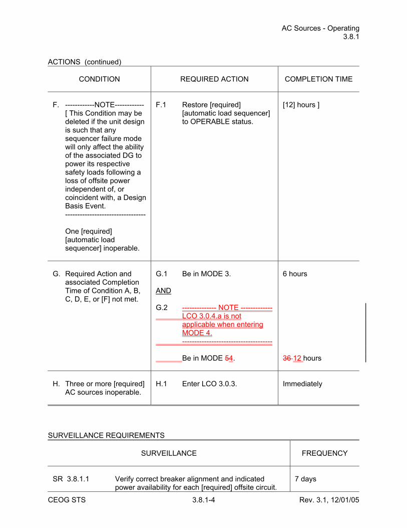
AC Sources - Operating 3.8.1
CEOG STS 3.8.1-4 Rev. 3.1, 12/01/05
ACTIONS (continued)
CONDITION
REQUIRED ACTION
COMPLETION TIME
F. ------------NOTE------------ [ This Condition may be
deleted if the unit design is such that any sequencer failure mode will only affect the ability of the associated DG to power its respective safety loads following a loss of offsite power independent of, or coincident with, a Design Basis Event.
--------------------------------- One [required]
[automatic load sequencer] inoperable.
F.1 Restore [required]
[automatic load sequencer] to OPERABLE status.
[12] hours ]
G. Required Action and
associated Completion Time of Condition A, B, C, D, E, or [F] not met.
G.1 Be in MODE 3. AND G.2 -------------- NOTE ------------- LCO 3.0.4.a is not
applicable when entering MODE 4.
------------------------------------- Be in MODE 54.
6 hours 36 12 hours
H. Three or more [required]
AC sources inoperable.
H.1 Enter LCO 3.0.3.
Immediately
SURVEILLANCE REQUIREMENTS
SURVEILLANCE
FREQUENCY
SR 3.8.1.1 Verify correct breaker alignment and indicated
power availability for each [required] offsite circuit.
7 days
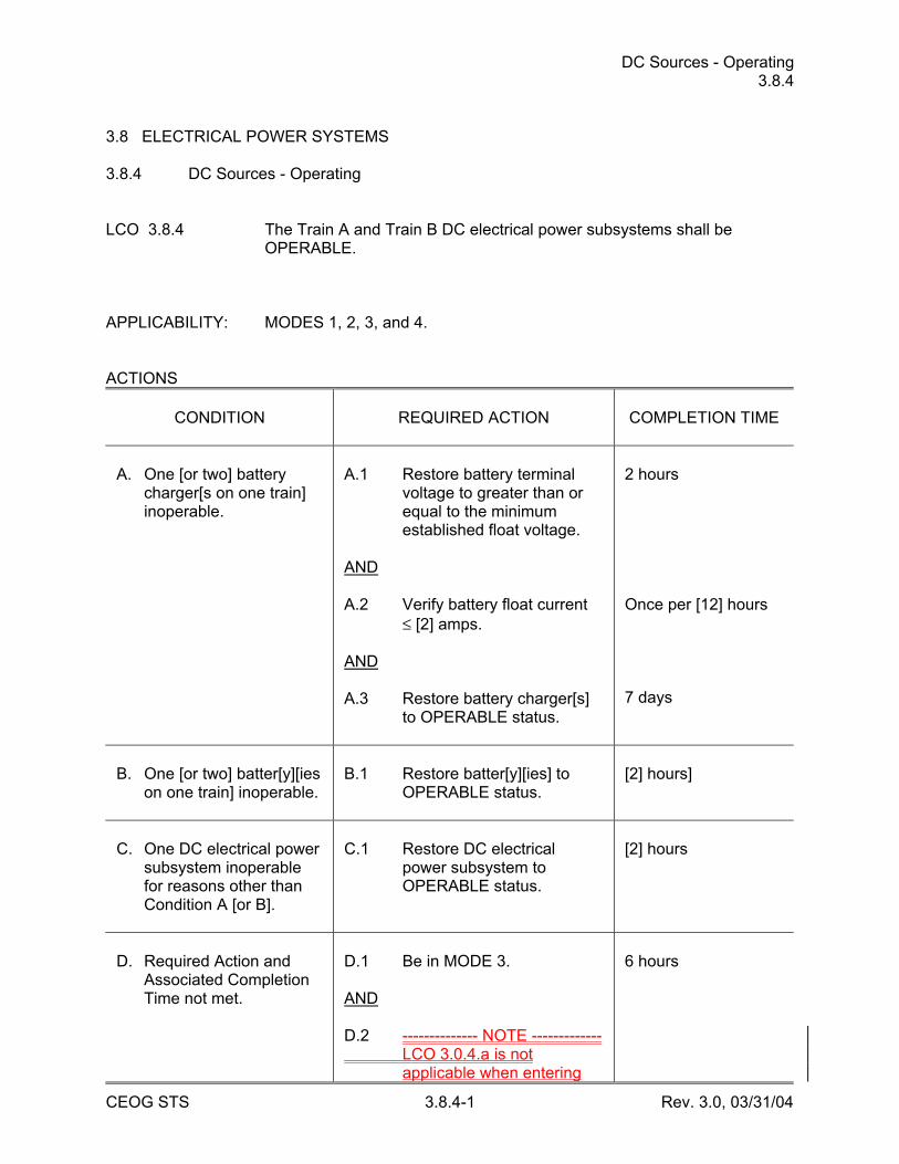
DC Sources - Operating 3.8.4
CEOG STS 3.8.4-1 Rev. 3.0, 03/31/04
3.8 ELECTRICAL POWER SYSTEMS 3.8.4 DC Sources - Operating LCO 3.8.4 The Train A and Train B DC electrical power subsystems shall be
OPERABLE. APPLICABILITY: MODES 1, 2, 3, and 4. ACTIONS
CONDITION
REQUIRED ACTION
COMPLETION TIME
A. One [or two] battery
charger[s on one train] inoperable.
A.1 Restore battery terminal
voltage to greater than or equal to the minimum established float voltage.
AND A.2 Verify battery float current
≤ [2] amps. AND A.3 Restore battery charger[s]
to OPERABLE status.
2 hours Once per [12] hours 7 days
B. One [or two] batter[y][ies
on one train] inoperable.
B.1 Restore batter[y][ies] to
OPERABLE status.
[2] hours]
C. One DC electrical power
subsystem inoperable for reasons other than Condition A [or B].
C.1 Restore DC electrical
power subsystem to OPERABLE status.
[2] hours
D. Required Action and
Associated Completion Time not met.
D.1 Be in MODE 3. AND D.2 -------------- NOTE ------------- LCO 3.0.4.a is not
applicable when entering
6 hours
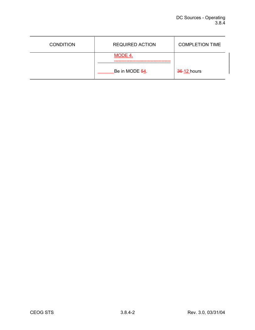
DC Sources - Operating 3.8.4
CEOG STS 3.8.4-2 Rev. 3.0, 03/31/04
CONDITION
REQUIRED ACTION
COMPLETION TIME
MODE 4.
------------------------------------- Be in MODE 54.
36 12 hours
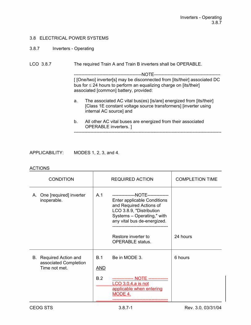
Inverters - Operating 3.8.7
CEOG STS 3.8.7-1 Rev. 3.0, 03/31/04
3.8 ELECTRICAL POWER SYSTEMS 3.8.7 Inverters - Operating LCO 3.8.7 The required Train A and Train B inverters shall be OPERABLE. ---------------------------------------------NOTE-------------------------------------------- [ [One/two] inverter[s] may be disconnected from [its/their] associated DC
bus for ≤ 24 hours to perform an equalizing charge on [its/their] associated [common] battery, provided:
a. The associated AC vital bus(es) [is/are] energized from [its/their]
[Class 1E constant voltage source transformers] [inverter using internal AC source] and
b. All other AC vital buses are energized from their associated
OPERABLE inverters. ] -------------------------------------------------------------------------------------------------- APPLICABILITY: MODES 1, 2, 3, and 4. ACTIONS
CONDITION
REQUIRED ACTION
COMPLETION TIME
A. One [required] inverter
inoperable.
A.1 ---------------NOTE-------------- Enter applicable Conditions
and Required Actions of LCO 3.8.9, "Distribution Systems – Operating," with any vital bus de-energized.
------------------------------------- Restore inverter to
OPERABLE status.
24 hours
B. Required Action and
associated Completion Time not met.
B.1 Be in MODE 3. AND B.2 -------------- NOTE ------------- LCO 3.0.4.a is not
applicable when entering MODE 4.
-------------------------------------
6 hours
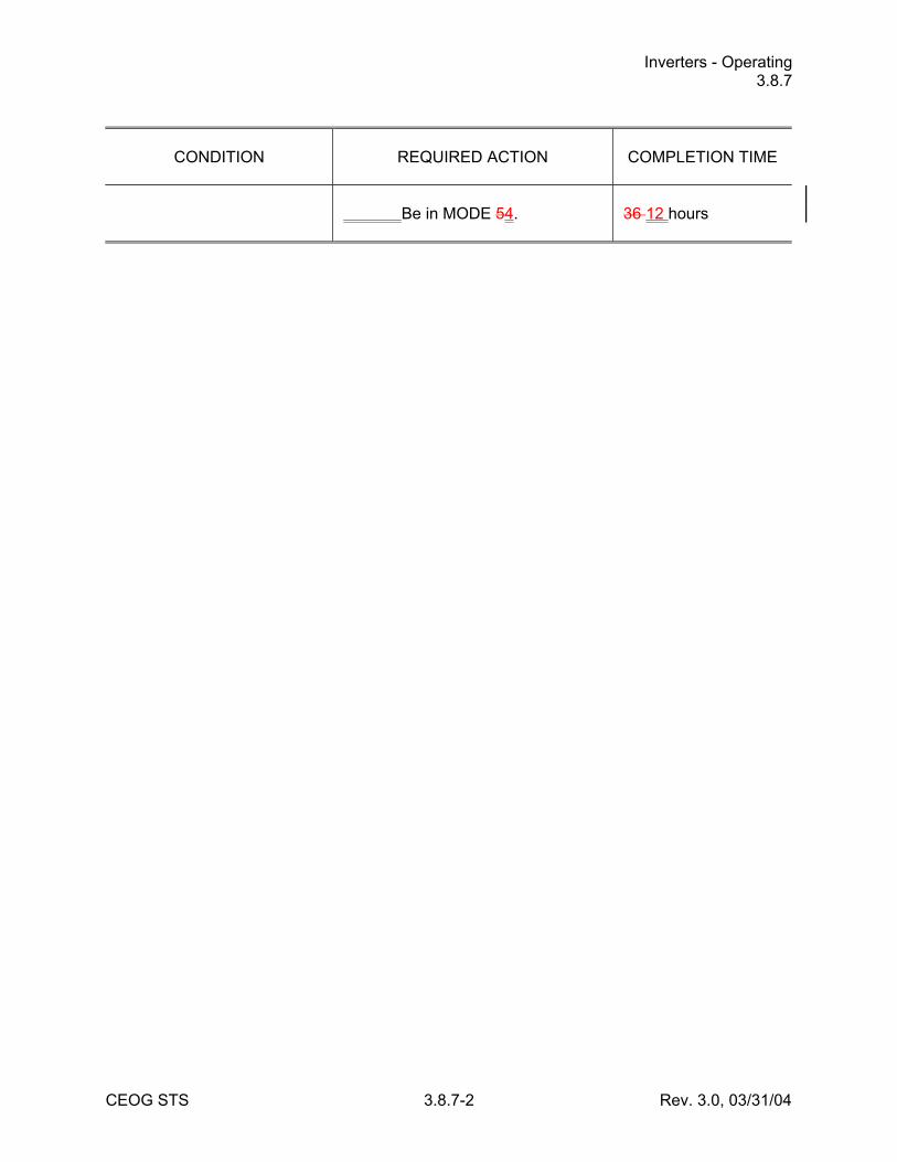
Inverters - Operating 3.8.7
CEOG STS 3.8.7-2 Rev. 3.0, 03/31/04
CONDITION
REQUIRED ACTION
COMPLETION TIME
Be in MODE 54.
36 12 hours
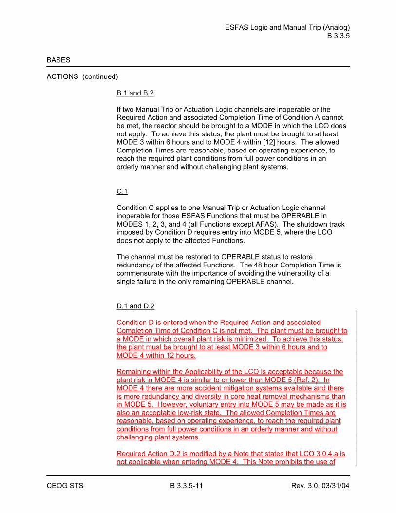
ESFAS Logic and Manual Trip (Analog) B 3.3.5
CEOG STS B 3.3.5-11 Rev. 3.0, 03/31/04
BASES ACTIONS (continued)
B.1 and B.2 If two Manual Trip or Actuation Logic channels are inoperable or the Required Action and associated Completion Time of Condition A cannot be met, the reactor should be brought to a MODE in which the LCO does not apply. To achieve this status, the plant must be brought to at least MODE 3 within 6 hours and to MODE 4 within [12] hours. The allowed Completion Times are reasonable, based on operating experience, to reach the required plant conditions from full power conditions in an orderly manner and without challenging plant systems. C.1 Condition C applies to one Manual Trip or Actuation Logic channel inoperable for those ESFAS Functions that must be OPERABLE in MODES 1, 2, 3, and 4 (all Functions except AFAS). The shutdown track imposed by Condition D requires entry into MODE 5, where the LCO does not apply to the affected Functions. The channel must be restored to OPERABLE status to restore redundancy of the affected Functions. The 48 hour Completion Time is commensurate with the importance of avoiding the vulnerability of a single failure in the only remaining OPERABLE channel. D.1 and D.2 Condition D is entered when the Required Action and associated Completion Time of Condition C is not met. The plant must be brought to a MODE in which overall plant risk is minimized. To achieve this status, the plant must be brought to at least MODE 3 within 6 hours and to MODE 4 within 12 hours. Remaining within the Applicability of the LCO is acceptable because the plant risk in MODE 4 is similar to or lower than MODE 5 (Ref. 2). In MODE 4 there are more accident mitigation systems available and there is more redundancy and diversity in core heat removal mechanisms than in MODE 5. However, voluntary entry into MODE 5 may be made as it is also an acceptable low-risk state. The allowed Completion Times are reasonable, based on operating experience, to reach the required plant conditions from full power conditions in an orderly manner and without challenging plant systems. Required Action D.2 is modified by a Note that states that LCO 3.0.4.a is not applicable when entering MODE 4. This Note prohibits the use of
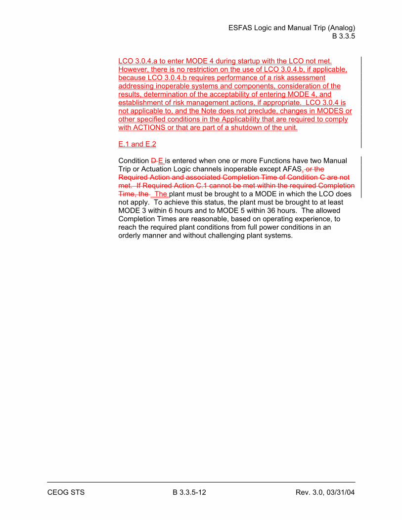
ESFAS Logic and Manual Trip (Analog) B 3.3.5
CEOG STS B 3.3.5-12 Rev. 3.0, 03/31/04
LCO 3.0.4.a to enter MODE 4 during startup with the LCO not met. However, there is no restriction on the use of LCO 3.0.4.b, if applicable, because LCO 3.0.4.b requires performance of a risk assessment addressing inoperable systems and components, consideration of the results, determination of the acceptability of entering MODE 4, and establishment of risk management actions, if appropriate. LCO 3.0.4 is not applicable to, and the Note does not preclude, changes in MODES or other specified conditions in the Applicability that are required to comply with ACTIONS or that are part of a shutdown of the unit. E.1 and E.2 Condition D E is entered when one or more Functions have two Manual Trip or Actuation Logic channels inoperable except AFAS. or the Required Action and associated Completion Time of Condition C are not met. If Required Action C.1 cannot be met within the required Completion Time, the The plant must be brought to a MODE in which the LCO does not apply. To achieve this status, the plant must be brought to at least MODE 3 within 6 hours and to MODE 5 within 36 hours. The allowed Completion Times are reasonable, based on operating experience, to reach the required plant conditions from full power conditions in an orderly manner and without challenging plant systems.
ESFAS Logic and Manual Trip (Analog) B 3.3.5
CEOG STS B 3.3.5-13 Rev. 3.0, 03/31/04
BASES SURVEILLANCE SR 3.3.5.1 REQUIREMENTS
A CHANNEL FUNCTIONAL TEST is performed every 92 days to ensure the entire channel will perform its intended function when needed. Sensor subsystem tests are addressed in LCO 3.3.4. This SR addresses Actuation Logic tests. A successful test of the required contact(s) of a channel relay may be performed by the verification of the change of state of a single contact of the relay. This clarifies what is an acceptable CHANNEL FUNCTIONAL TEST of a relay. This is acceptable because all of the other required contacts of the relay are verified by other Technical Specifications and non-Technical Specifications tests at least once per refueling interval with applicable extensions. Actuation Logic Tests Actuation subsystem testing includes injecting one trip signal into each two-out-of-four logic subsystem in each ESFAS Function and using a bistable trip input to satisfy the trip logic. Initiation relays associated with the affected channel will then actuate the individual ESFAS components. Since each ESFAS Function employs subchannels of Actuation Logic, it is possible to actuate individual components without actuating an entire ESFAS Function. Note 1 requires that Actuation Logic tests include operation of initiation relays. Note 2 allows deferred at power testing of certain relays to allow for the fact that operating certain relays during power operation could cause plant transients or equipment damage. Those initiation relays that cannot be tested at power must be tested in accordance with Note 2. These include [SIAS No. 5, SIAS No. 10, CIAS No. 5, and MSIS No. 1.] These relays actuate the following components, which cannot be tested at power: • RCP seal bleedoff isolation valves, • Service water isolation valves, • VCT discharge valves, • Letdown stop valves, • CCW to and from the RCPs, • MSIVs and feedwater isolation valves, and • Instrument air containment isolation valves.
ESFAS Logic and Manual Trip (Analog) B 3.3.5
CEOG STS B 3.3.5-14 Rev. 3.0, 03/31/04
BASES SURVEILLANCE REQUIREMENTS (continued)
The reasons that each of the above cannot be fully tested at power are stated in Reference 1. These tests verify that the ESFAS is capable of performing its intended function, from bistable input through the actuated components. The Frequency of [92] days is based on the reliability analysis presented in topical report CEN-327, "RPS/ESFAS Extended Test Interval Evaluation" (Ref. 23). SR 3.3.5.2 A CHANNEL FUNCTIONAL TEST is performed on the manual ESFAS actuation circuitry, de-energizing relays and providing Manual Trip of the Function. A successful test of the required contact(s) of a channel relay may be performed by the verification of the change of state of a single contact of the relay. This clarifies what is an acceptable CHANNEL FUNCTIONAL TEST of a relay. This is acceptable because all of the other required contacts of the relay are verified by other Technical Specifications and non-Technical Specifications tests at least once per refueling interval with applicable extensions. This Surveillance verifies that the trip push buttons are capable of opening contacts in the Actuation Logic as designed, de-energizing the initiation relays and providing Manual Trip of the Function. The [18] month Frequency is based on the need to perform this Surveillance under the conditions that apply during a plant outage and the potential for an unplanned transient if the Surveillance were performed with the reactor at power. Operating experience has shown these components usually pass the Surveillance when performed at a Frequency of once every [18] months.
REFERENCES 1. FSAR, Section [7.3]. 2. CE NPSD-1186-A, Technical Justification for the Risk Informed
Modification to Selected Required Action End States for CEOG PWRs, October, 2001.
23. CEN-327, June 2, 1986, including Supplement 1, March 3, 1989.
ESFAS Logic and Manual Trip (Digital) B 3.3.6
CEOG STS B 3.3.6-17 Rev. 3.0, 03/31/04
BASES ACTIONS (continued)
E.1 and E.2 If two associated Actuation Logic channels are inoperable, or if the Required Actions and associated Completion Times of Conditions for CSAS, MSIS, or EFAS cannot be met, the plant must be brought to a MODE in which the LCO does not apply overall plant risk is minimized. To achieve this status, the plant must be brought to at least MODE 3 within 6 hours and to MODE 4 within [12] hours. Remaining within the Applicability of the LCO is acceptable because the plant risk in MODE 4 is similar to or lower than MODE 5 (Ref. 2). In MODE 4 there are more accident mitigation systems available and there is more redundancy and diversity in core heat removal mechanisms than in MODE 5. However, voluntary entry into MODE 5 may be made as it is also an acceptable low-risk state. Required Action E.2 is modified by a Note that states that LCO 3.0.4.a is not applicable when entering MODE 4. This Note prohibits the use of LCO 3.0.4.a to enter MODE 4 during startup with the LCO not met. However, there is no restriction on the use of LCO 3.0.4.b, if applicable, because LCO 3.0.4.b requires performance of a risk assessment addressing inoperable systems and components, consideration of the results, determination of the acceptability of entering MODE 4, and establishment of risk management actions, if appropriate. LCO 3.0.4 is not applicable to, and the Note does not preclude, changes in MODES or other specified conditions in the Applicability that are required to comply with ACTIONS or that are part of a shutdown of the unit. The allowed Completion Times are reasonable, based on operating experience, to reach the required plant conditions from full power conditions in an orderly manner and without challenging plant systems. F.1 and F.2 If two associated Actuation Logic channels are inoperable, or if the Required Actions and associated Completion Times for SIAS, CIAS, RAS, or CCAS are not met, the plant must be brought to a MODE in which the LCO does not apply. To achieve this status, the plant must be brought to at least MODE 3 within 6 hours and to MODE 5 within 36 hours. The allowed Completion Times are reasonable, based on operating experience, to reach the required plant conditions from full power conditions in an orderly manner and without challenging plant systems.
ESFAS Logic and Manual Trip (Digital) B 3.3.6
CEOG STS B 3.3.6-18 Rev. 3.0, 03/31/04
SURVEILLANCE SR 3.3.6.1 REQUIREMENTS
A CHANNEL FUNCTIONAL TEST is performed every [92] days to ensure the entire channel will perform its intended function when needed. A successful test of the required contact(s) of a channel relay may be performed by the verification of the change of state of a single contact of the relay. This clarifies what is an acceptable CHANNEL FUNCTIONAL TEST of a relay. This is acceptable because all of the other required contacts of the relay are verified by other Technical Specifications and non-Technical Specifications tests at least once per refueling interval with applicable extensions.
ESFAS Logic and Manual Trip (Digital) B 3.3.6
CEOG STS B 3.3.6-19 Rev. 3.0, 03/31/04
BASES SURVEILLANCE REQUIREMENTS (continued)
The CHANNEL FUNCTIONAL TEST is part of an overlapping test sequence similar to that employed in the RPS. This sequence, consisting of SR 3.3.5.2, SR 3.3.6.1, and SR 3.3.6.2, tests the entire ESFAS from the bistable input through the actuation of the individual subgroup relays. These overlapping tests are described in Reference 1. SR 3.3.5.2 and SR 3.3.6.1 are normally performed together and in conjunction with ESFAS testing. SR 3.3.6.2 verifies that the subgroup relays are capable of actuating their respective ESF components when de-energized. These tests verify that the ESFAS is capable of performing its intended function, from bistable input through the actuated components. SR 3.3.5.2 is addressed in LCO 3.3.5. SR 3.3.6.1 includes Matrix Logic tests and trip path (Initiation Logic) tests. Matrix Logic Tests These tests are performed one matrix at a time. They verify that a coincidence in the two input channels for each function removes power to the matrix relays. During testing, power is applied to the matrix relay test coils, preventing the matrix relay contacts from assuming their energized state. The Matrix Logic tests will detect any short circuits around the bistable contacts in the coincidence logic, such as may be caused by faulty bistable relay or trip channel bypass contacts. Trip Path (Initiation Logic) Tests These tests are similar to the Matrix Logic tests, except that test power is withheld from one matrix relay at a time, allowing the initiation circuit to de-energize, opening one contact in each Actuation Logic channel. The initiation circuit lockout relay must be reset (except for EFAS, which lacks initiation circuit lockout relays) prior to testing the other three initiation circuits, or an ESFAS actuation may result. Automatic Actuation Logic operation is verified during Initiation Logic testing by verifying that current is interrupted in each trip leg in the selective two-out-of-four actuation circuit logic whenever the initiation relay is de-energized. A Note is added to indicate that testing of Actuation Logic shall include verification of the proper operation of each initiation relay. The Frequency of [92] days is based on the reliability analysis presented in topical report CEN-327, "RPS/ESFAS Extended Test Interval Evaluation" (Ref. 23).
ESFAS Logic and Manual Trip (Digital) B 3.3.6
CEOG STS B 3.3.6-20 Rev. 3.0, 03/31/04
BASES SURVEILLANCE REQUIREMENTS (continued)
SR 3.3.6.2 Individual ESFAS subgroup relays must also be tested, one at a time, to verify the individual ESFAS components will actuate when required. Proper operation of the individual subgroup relays is verified by de-energizing these relays one at a time using an ARC mounted test circuit. Proper operation of each component actuated by the individual relays is thus verified without the need to actuate the entire ESFAS function. The 184 day Frequency is based on operating experience and ensures individual relay problems can be detected within this time frame. Considering the large number of similar relays in the ARC, and the similarity in their use, a large test sample can be assembled to verify the validity of this Frequency. The actual justification is based on CEN-403, "Relaxation of Surveillance Test Interval for ESFAS Subgroup Relay Testing" (Ref. 34). Some components cannot be tested at power since their actuation might lead to plant trip or equipment damage. Reference 1 lists those relays exempt from testing at power, with an explanation of the reason for each exception. Relays not tested at power must be tested in accordance with the Note to this SR. SR 3.3.6.3 A CHANNEL FUNCTIONAL TEST is performed on the manual ESFAS actuation circuitry, de-energizing relays and providing manual actuation of the function. A successful test of the required contact(s) of a channel relay may be performed by the verification of the change of state of a single contact of the relay. This clarifies what is an acceptable CHANNEL FUNCTIONAL TEST of a relay. This is acceptable because all of the other required contacts of the relay are verified by other Technical Specifications and non-Technical Specifications tests at least once per refueling interval with applicable extensions. This test verifies that the trip push buttons are capable of opening contacts in the Actuation Logic as designed. The [18] month Frequency is based on the need to perform this Surveillance under the conditions that apply during a plant outage and the potential for an unplanned transient if the Surveillance were performed with the reactor at power. Operating experience has shown these components usually pass the Surveillance when performed at a Frequency of once every [18] months.
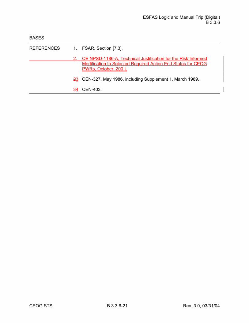
ESFAS Logic and Manual Trip (Digital) B 3.3.6
CEOG STS B 3.3.6-21 Rev. 3.0, 03/31/04
BASES REFERENCES 1. FSAR, Section [7.3]. 2. CE NPSD-1186-A, Technical Justification for the Risk Informed
Modification to Selected Required Action End States for CEOG PWRs, October, 200 I.
23. CEN-327, May 1986, including Supplement 1, March 1989. 34. CEN-403.
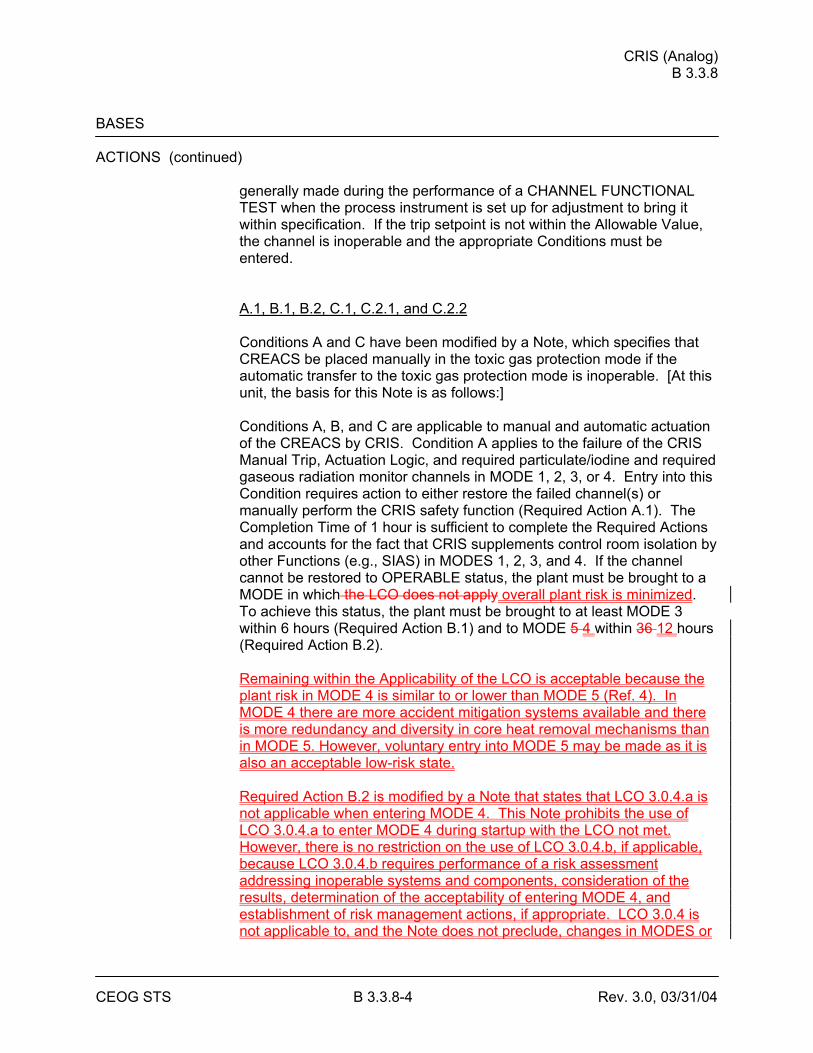
CRIS (Analog) B 3.3.8
CEOG STS B 3.3.8-4 Rev. 3.0, 03/31/04
BASES ACTIONS (continued)
generally made during the performance of a CHANNEL FUNCTIONAL TEST when the process instrument is set up for adjustment to bring it within specification. If the trip setpoint is not within the Allowable Value, the channel is inoperable and the appropriate Conditions must be entered. A.1, B.1, B.2, C.1, C.2.1, and C.2.2 Conditions A and C have been modified by a Note, which specifies that CREACS be placed manually in the toxic gas protection mode if the automatic transfer to the toxic gas protection mode is inoperable. [At this unit, the basis for this Note is as follows:] Conditions A, B, and C are applicable to manual and automatic actuation of the CREACS by CRIS. Condition A applies to the failure of the CRIS Manual Trip, Actuation Logic, and required particulate/iodine and required gaseous radiation monitor channels in MODE 1, 2, 3, or 4. Entry into this Condition requires action to either restore the failed channel(s) or manually perform the CRIS safety function (Required Action A.1). The Completion Time of 1 hour is sufficient to complete the Required Actions and accounts for the fact that CRIS supplements control room isolation by other Functions (e.g., SIAS) in MODES 1, 2, 3, and 4. If the channel cannot be restored to OPERABLE status, the plant must be brought to a MODE in which the LCO does not apply overall plant risk is minimized. To achieve this status, the plant must be brought to at least MODE 3 within 6 hours (Required Action B.1) and to MODE 5 4 within 36 12 hours (Required Action B.2). Remaining within the Applicability of the LCO is acceptable because the plant risk in MODE 4 is similar to or lower than MODE 5 (Ref. 4). In MODE 4 there are more accident mitigation systems available and there is more redundancy and diversity in core heat removal mechanisms than in MODE 5. However, voluntary entry into MODE 5 may be made as it is also an acceptable low-risk state. Required Action B.2 is modified by a Note that states that LCO 3.0.4.a is not applicable when entering MODE 4. This Note prohibits the use of LCO 3.0.4.a to enter MODE 4 during startup with the LCO not met. However, there is no restriction on the use of LCO 3.0.4.b, if applicable, because LCO 3.0.4.b requires performance of a risk assessment addressing inoperable systems and components, consideration of the results, determination of the acceptability of entering MODE 4, and establishment of risk management actions, if appropriate. LCO 3.0.4 is not applicable to, and the Note does not preclude, changes in MODES or
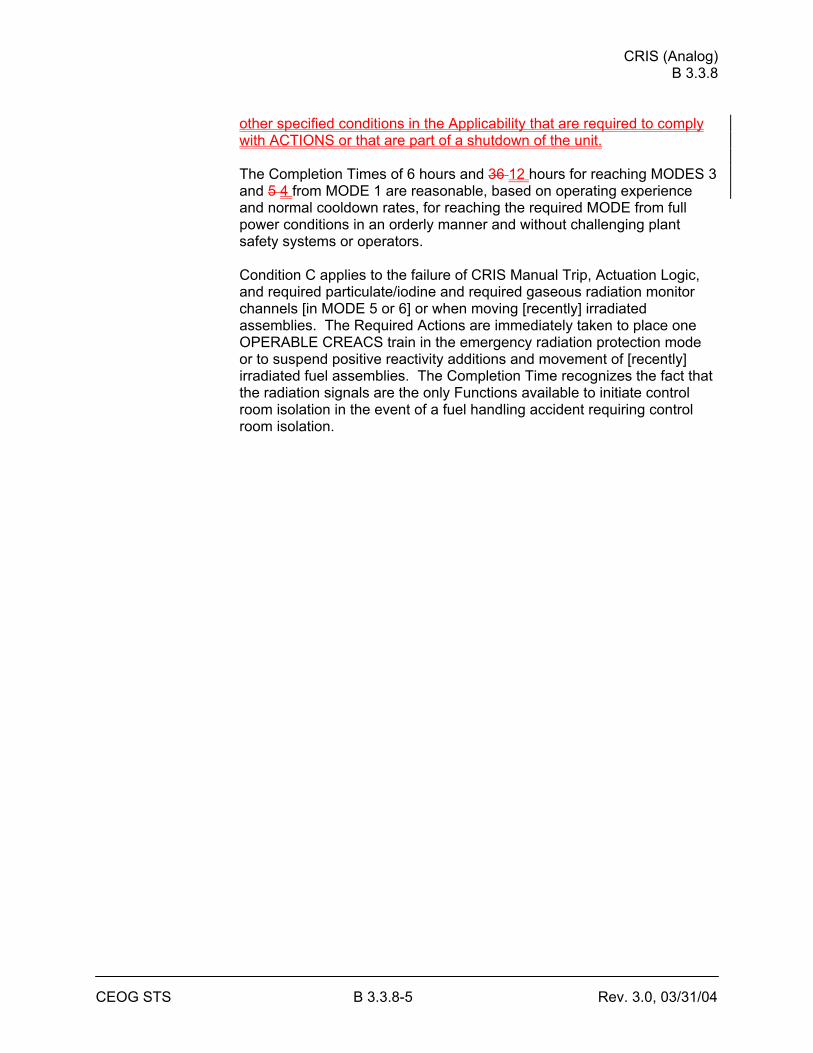
CRIS (Analog) B 3.3.8
CEOG STS B 3.3.8-5 Rev. 3.0, 03/31/04
other specified conditions in the Applicability that are required to comply with ACTIONS or that are part of a shutdown of the unit. The Completion Times of 6 hours and 36 12 hours for reaching MODES 3 and 5 4 from MODE 1 are reasonable, based on operating experience and normal cooldown rates, for reaching the required MODE from full power conditions in an orderly manner and without challenging plant safety systems or operators. Condition C applies to the failure of CRIS Manual Trip, Actuation Logic, and required particulate/iodine and required gaseous radiation monitor channels [in MODE 5 or 6] or when moving [recently] irradiated assemblies. The Required Actions are immediately taken to place one OPERABLE CREACS train in the emergency radiation protection mode or to suspend positive reactivity additions and movement of [recently] irradiated fuel assemblies. The Completion Time recognizes the fact that the radiation signals are the only Functions available to initiate control room isolation in the event of a fuel handling accident requiring control room isolation.
CRIS (Analog) B 3.3.8
CEOG STS B 3.3.8-7 Rev. 3.0, 03/31/04
BASES SURVEILLANCE REQUIREMENTS (continued)
SR 3.3.8.2 A CHANNEL FUNCTIONAL TEST is performed on the required control room radiation monitoring channel to ensure the entire channel will perform its intended function. A successful test of the required contact(s) of a channel relay may be performed by the verification of the change of state of a single contact of the relay. This clarifies what is an acceptable CHANNEL FUNCTIONAL TEST of a relay. This is acceptable because all of the other required contacts of the relay are verified by other Technical Specifications and non-Technical Specifications tests at least once per refueling interval with applicable extensions. Any setpoint adjustment shall be consistent with the assumptions of the current plant specific setpoint analysis. The as found and as left values must also be recorded and reviewed for consistency with the assumptions of the frequency extension analysis. The requirements for this review are outlined in Reference [45]. The Frequency of [92] days is based on plant operating experience with regard to channel OPERABILITY and drift, which demonstrates that failure of more than one channel of a given Function in any [92] day interval is a rare event. SR 3.3.8.3 Proper operation of the individual initiation relays is verified by de-energizing these relays during the CHANNEL FUNCTIONAL TEST of the Actuation Logic every [31] days. This will actuate the Function, operating all associated equipment. Proper operation of the equipment actuated by each train is thus verified. A successful test of the required contact(s) of a channel relay may be performed by the verification of the change of state of a single contact of the relay. This clarifies what is an acceptable CHANNEL FUNCTIONAL TEST of a relay. This is acceptable because all of the other required contacts of the relay are verified by other Technical Specifications and non-Technical Specifications tests at least once per refueling interval with applicable extensions. The Frequency of [31] days is based on plant operating experience with regard to channel OPERABILITY, which demonstrates that failure of more than one channel of a given Function in any [31] days interval is a rare event.
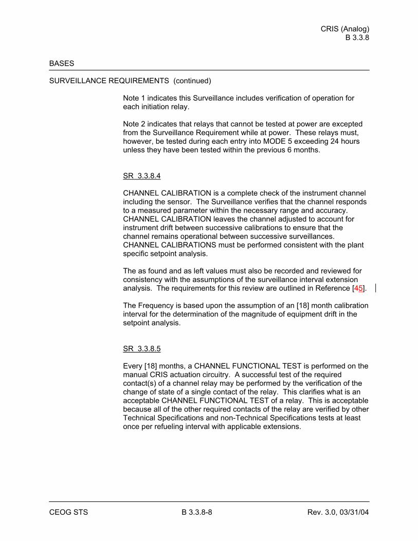
CRIS (Analog) B 3.3.8
CEOG STS B 3.3.8-8 Rev. 3.0, 03/31/04
BASES SURVEILLANCE REQUIREMENTS (continued)
Note 1 indicates this Surveillance includes verification of operation for each initiation relay. Note 2 indicates that relays that cannot be tested at power are excepted from the Surveillance Requirement while at power. These relays must, however, be tested during each entry into MODE 5 exceeding 24 hours unless they have been tested within the previous 6 months. SR 3.3.8.4 CHANNEL CALIBRATION is a complete check of the instrument channel including the sensor. The Surveillance verifies that the channel responds to a measured parameter within the necessary range and accuracy. CHANNEL CALIBRATION leaves the channel adjusted to account for instrument drift between successive calibrations to ensure that the channel remains operational between successive surveillances. CHANNEL CALIBRATIONS must be performed consistent with the plant specific setpoint analysis. The as found and as left values must also be recorded and reviewed for consistency with the assumptions of the surveillance interval extension analysis. The requirements for this review are outlined in Reference [45]. The Frequency is based upon the assumption of an [18] month calibration interval for the determination of the magnitude of equipment drift in the setpoint analysis. SR 3.3.8.5 Every [18] months, a CHANNEL FUNCTIONAL TEST is performed on the manual CRIS actuation circuitry. A successful test of the required contact(s) of a channel relay may be performed by the verification of the change of state of a single contact of the relay. This clarifies what is an acceptable CHANNEL FUNCTIONAL TEST of a relay. This is acceptable because all of the other required contacts of the relay are verified by other Technical Specifications and non-Technical Specifications tests at least once per refueling interval with applicable extensions.
CRIS (Analog) B 3.3.8
CEOG STS B 3.3.8-9 Rev. 3.0, 03/31/04
BASES SURVEILLANCE REQUIREMENTS (continued)
This test verifies that the trip push buttons are capable of opening contacts in the Actuation Logic as designed, de-energizing the initiation relays and providing Manual Trip of the function. The [18] month Frequency is based on the need to perform this Surveillance under the conditions that apply during a plant outage and the potential for an unplanned transient if the Surveillance were performed with the reactor at power. Operating experience has shown these components usually pass the Surveillance when performed at a Frequency of once every [18] months.
[ SR 3.3.8.6 This Surveillance ensures that the train actuation response times are less than the maximum times assumed in the analyses. The [18] month Frequency is based upon plant operating experience, which shows that random failures of instrumentation components causing serious response time degradation, but not channel failure, are infrequent occurrences. Testing of the final actuating devices, which make up the bulk of the response time, is included in the Surveillance testing. ]
REFERENCES 1. FSAR, Chapter [15]. 2. "Plant Protection System Selection of Trip Setpoint Values." 3. 10 CFR 50, Appendix A, GDC 19. 4. CE NPSD-1186-A, Technical Justification for the Risk Informed
Modification to Selected Required Action End States for CEOG PWRs, October, 2001.
45. [ ].
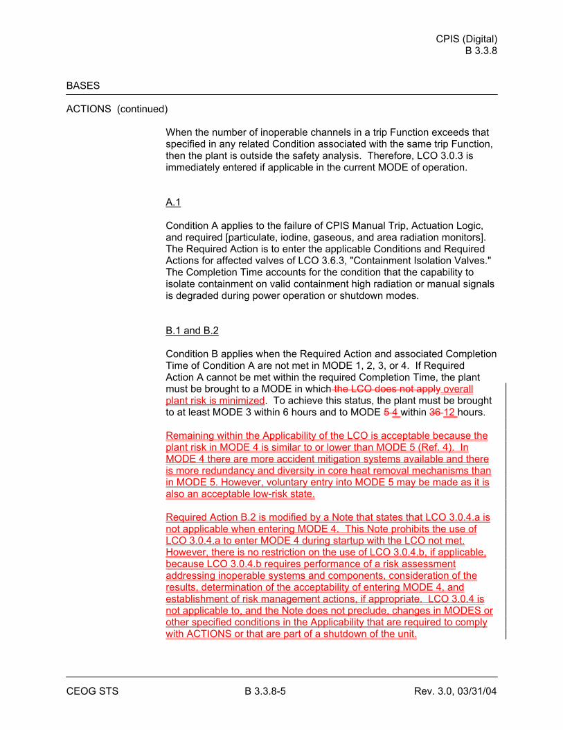
CPIS (Digital) B 3.3.8
CEOG STS B 3.3.8-5 Rev. 3.0, 03/31/04
BASES ACTIONS (continued)
When the number of inoperable channels in a trip Function exceeds that specified in any related Condition associated with the same trip Function, then the plant is outside the safety analysis. Therefore, LCO 3.0.3 is immediately entered if applicable in the current MODE of operation. A.1 Condition A applies to the failure of CPIS Manual Trip, Actuation Logic, and required [particulate, iodine, gaseous, and area radiation monitors]. The Required Action is to enter the applicable Conditions and Required Actions for affected valves of LCO 3.6.3, "Containment Isolation Valves." The Completion Time accounts for the condition that the capability to isolate containment on valid containment high radiation or manual signals is degraded during power operation or shutdown modes. B.1 and B.2 Condition B applies when the Required Action and associated Completion Time of Condition A are not met in MODE 1, 2, 3, or 4. If Required Action A cannot be met within the required Completion Time, the plant must be brought to a MODE in which the LCO does not apply overall plant risk is minimized. To achieve this status, the plant must be brought to at least MODE 3 within 6 hours and to MODE 5 4 within 36 12 hours. Remaining within the Applicability of the LCO is acceptable because the plant risk in MODE 4 is similar to or lower than MODE 5 (Ref. 4). In MODE 4 there are more accident mitigation systems available and there is more redundancy and diversity in core heat removal mechanisms than in MODE 5. However, voluntary entry into MODE 5 may be made as it is also an acceptable low-risk state. Required Action B.2 is modified by a Note that states that LCO 3.0.4.a is not applicable when entering MODE 4. This Note prohibits the use of LCO 3.0.4.a to enter MODE 4 during startup with the LCO not met. However, there is no restriction on the use of LCO 3.0.4.b, if applicable, because LCO 3.0.4.b requires performance of a risk assessment addressing inoperable systems and components, consideration of the results, determination of the acceptability of entering MODE 4, and establishment of risk management actions, if appropriate. LCO 3.0.4 is not applicable to, and the Note does not preclude, changes in MODES or other specified conditions in the Applicability that are required to comply with ACTIONS or that are part of a shutdown of the unit.
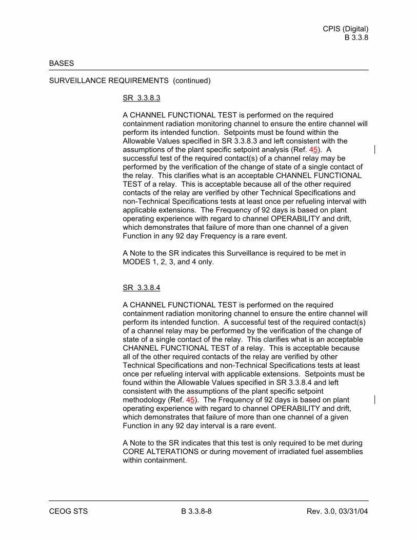
CPIS (Digital) B 3.3.8
CEOG STS B 3.3.8-8 Rev. 3.0, 03/31/04
BASES SURVEILLANCE REQUIREMENTS (continued)
SR 3.3.8.3 A CHANNEL FUNCTIONAL TEST is performed on the required containment radiation monitoring channel to ensure the entire channel will perform its intended function. Setpoints must be found within the Allowable Values specified in SR 3.3.8.3 and left consistent with the assumptions of the plant specific setpoint analysis (Ref. 45). A successful test of the required contact(s) of a channel relay may be performed by the verification of the change of state of a single contact of the relay. This clarifies what is an acceptable CHANNEL FUNCTIONAL TEST of a relay. This is acceptable because all of the other required contacts of the relay are verified by other Technical Specifications and non-Technical Specifications tests at least once per refueling interval with applicable extensions. The Frequency of 92 days is based on plant operating experience with regard to channel OPERABILITY and drift, which demonstrates that failure of more than one channel of a given Function in any 92 day Frequency is a rare event. A Note to the SR indicates this Surveillance is required to be met in MODES 1, 2, 3, and 4 only. SR 3.3.8.4 A CHANNEL FUNCTIONAL TEST is performed on the required containment radiation monitoring channel to ensure the entire channel will perform its intended function. A successful test of the required contact(s) of a channel relay may be performed by the verification of the change of state of a single contact of the relay. This clarifies what is an acceptable CHANNEL FUNCTIONAL TEST of a relay. This is acceptable because all of the other required contacts of the relay are verified by other Technical Specifications and non-Technical Specifications tests at least once per refueling interval with applicable extensions. Setpoints must be found within the Allowable Values specified in SR 3.3.8.4 and left consistent with the assumptions of the plant specific setpoint methodology (Ref. 45). The Frequency of 92 days is based on plant operating experience with regard to channel OPERABILITY and drift, which demonstrates that failure of more than one channel of a given Function in any 92 day interval is a rare event. A Note to the SR indicates that this test is only required to be met during CORE ALTERATIONS or during movement of irradiated fuel assemblies within containment.
CPIS (Digital) B 3.3.8
CEOG STS B 3.3.8-9 Rev. 3.0, 03/31/04
BASES SURVEILLANCE REQUIREMENTS (continued)
SR 3.3.8.5 Proper operation of the individual initiation relays is verified by actuating these relays during the CHANNEL FUNCTIONAL TEST of the Actuation Logic every [18] months. This will actuate the Function, operating all associated equipment. Proper operation of the equipment actuated by each train is thus verified. The Frequency of [18] months is based on plant operating experience with regard to channel OPERABILITY and drift, which demonstrates that failure of more than one channel of a given Function during any [18] month interval is a rare event. A successful test of the required contact(s) of a channel relay may be performed by the verification of the change of state of a single contact of the relay. This clarifies what is an acceptable CHANNEL FUNCTIONAL TEST of a relay. This is acceptable because all of the other required contacts of the relay are verified by other Technical Specifications and non-Technical Specifications tests at least once per refueling interval with applicable extensions. A Note to the SR indicates that this Surveillance includes verification of operation for each initiation relay. SR 3.3.8.6 CHANNEL CALIBRATION is a complete check of the instrument channel including the sensor. The Surveillance verifies that the channel responds to a measured parameter within the necessary range and accuracy. CHANNEL CALIBRATION leaves the channel adjusted to account for instrument drift between successive calibrations to ensure that the channel remains operational between successive surveillances. CHANNEL CALIBRATIONS must be performed consistent with the plant specific setpoint analysis. The as found and as left values must also be recorded and reviewed for consistency with the assumptions of the surveillance interval extension analysis. The requirements for this review are outlined in Reference [56]. The [18] month Frequency is based on the need to perform this Surveillance under the conditions that apply during a plant outage and the potential for an unplanned transient if the Surveillance were performed with the reactor at power.
CPIS (Digital) B 3.3.8
CEOG STS B 3.3.8-10 Rev. 3.0, 03/31/04
BASES SURVEILLANCE REQUIREMENTS (continued)
SR 3.3.8.7 This Surveillance ensures that the train actuation response times are less than or equal to the maximum times assumed in the analyses. The [18] month Frequency is based upon plant operating experience, which shows that random failures of instrumentation components causing serious response time degradation, but not channel failure, are infrequent occurrences. Testing of the final actuating devices, which make up the bulk of the response time, is included in the Surveillance. SR 3.3.8.8 Every [18] months, a CHANNEL FUNCTIONAL TEST is performed on the CPIS Manual Trip channel. A successful test of the required contact(s) of a channel relay may be performed by the verification of the change of state of a single contact of the relay. This clarifies what is an acceptable CHANNEL FUNCTIONAL TEST of a relay. This is acceptable because all of the other required contacts of the relay are verified by other Technical Specifications and non-Technical Specifications tests at least once per refueling interval with applicable extensions. This test verifies that the trip push buttons are capable of opening contacts in the Actuation Logic as designed, de-energizing the initiation relays and providing manual actuation of the Function. The [18] month Frequency is based on the need to perform this Surveillance under the conditions that apply during a plant outage and the potential for an unplanned transient if the Surveillance were performed with the reactor at power. Operating experience has shown these components usually pass the Surveillance when performed at a Frequency of once every [18] months.
REFERENCES 1. FSAR, Chapter [15]. 2. "Plant Protection System Selection of Trip Setpoint Values." 3. 10 CFR 100. 4. CE NPSD-1186-A, Technical Justification for the Risk Informed
Modification to Selected Required Action End States for CEOG PWRs, October, 2001.
45. Plant Specific Setpoint Methodology. 56. [ ].
CVCS Isolation signal (Analog) B 3.3.9
CEOG STS B 3.3.9-5 Rev. 3.0, 03/31/04
BASES ACTIONS (continued)
Once the Required Action to trip or bypass the channel has been complied with, Required Action C.2 provides for restoring one channel to OPERABLE status within 48 hours. The justification of the 48 hour Completion Time is the same as for Condition B. After one channel is restored to OPERABLE status, the provisions of Condition C still apply to the remaining inoperable channel. D.1 and D.2 Condition D is entered when the Required Actions and associated Completion Times of Condition A, B, or C are not met. The plant must be brought to a MODE in which overall plant risk is minimized. To achieve this status, the plant must be brought to at least MODE 3 within 6 hours and to MODE 4 within 12 hours. Remaining within the Applicability of the LCO is acceptable because the plant risk in MODE 4 is similar to or lower than MODE 5 (Ref. 3). In MODE 4 there are more accident mitigation systems available and there is more redundancy and diversity in core heat removal mechanisms than in MODE 5. However, voluntary entry into MODE 5 may be made as it is also an acceptable low-risk state. The allowed Completion Times are reasonable, based on operating experience, to reach the required plant conditions from full power conditions in an orderly manner and without challenging plant systems. Required Action D.2 is modified by a Note that states that LCO 3.0.4.a is not applicable when entering MODE 4. This Note prohibits the use of LCO 3.0.4.a to enter MODE 4 during startup with the LCO not met. However, there is no restriction on the use of LCO 3.0.4.b, if applicable, because LCO 3.0.4.b requires performance of a risk assessment addressing inoperable systems and components, consideration of the results, determination of the acceptability of entering MODE 4, and establishment of risk management actions, if appropriate. LCO 3.0.4 is not applicable to, and the Note does not preclude, changes in MODES or other specified conditions in the Applicability that are required to comply with ACTIONS or that are part of a shutdown of the unit. DE.1 and DE.2 Condition D E specifies the shutdown track to be followed if two Actuation Logic channels are inoperable or if the Required Actions and associated Completion Times of Condition A, B, or C are not met. If two Actuation Logic channels are inoperable or the Required Actions cannot be met
CVCS Isolation signal (Analog) B 3.3.9
CEOG STS B 3.3.9-6 Rev. 3.0, 03/31/04
within the required Completion Time, the The plant must be brought to a MODE in which the LCO does not apply. To achieve this status, the plant must be brought to at least MODE 3 within 6 hours and to MODE 5 within 36 hours. The Completion Times are reasonable, based on operating experience, to reach the required MODE from full power conditions in an orderly manner and without challenging plant systems.
SURVEILLANCE SR 3.3.9.1 REQUIREMENTS
Performance of the CHANNEL CHECK on each CVCS isolation pressure indicating channel once every 12 hours ensures that a gross failure of instrumentation has not occurred. A CHANNEL CHECK is normally a comparison of the parameter indicated on one channel to a similar parameter on other channels. It is based on the assumption that instrument channels monitoring the same parameter should read approximately the same value. Significant deviations between the two instrument channels could be an indication of excessive instrument drift in one of the channels or of something even more serious. CHANNEL CHECK will detect gross channel failure; thus, it is key to verifying the instrumentation continues to operate properly between each CHANNEL CALIBRATION. Agreement criteria are determined by the plant staff based on a combination of the channel instrument uncertainties, including indication and readability. If a channel is outside the criteria, it may be an indication that the transmitter or the signal processing equipment has drifted outside its limit.
CVCS Isolation signal (Analog) B 3.3.9
CEOG STS B 3.3.9-7 Rev. 3.0, 03/31/04
BASES SURVEILLANCE REQUIREMENTS (continued)
The Frequency, about once every shift, is based on operating experience that demonstrates the rarity of channel failure. Since the probability of two random failures in redundant channels in any 12 hour period is low, the CHANNEL CHECK minimizes the chance of loss of protective function due to failure of redundant channels. The CHANNEL CHECK supplements less formal, but more frequent, checks of channel OPERABILITY during normal operational use of the displays associated with the LCO required channels. SR 3.3.9.2 A CHANNEL FUNCTIONAL TEST is performed on each channel to ensure the entire channel will perform its intended function. A successful test of the required contact(s) of a channel relay may be performed by the verification of the change of state of a single contact of the relay. This clarifies what is an acceptable CHANNEL FUNCTIONAL TEST of a relay. This is acceptable because all of the other required contacts of the relay are verified by other Technical Specifications and non-Technical Specifications tests at least once per refueling interval with applicable extensions. Any setpoint adjustment shall be consistent with the assumptions of the current plant specific setpoint analysis. The as found and as left values must also be recorded and reviewed for consistency with the assumptions of the surveillance interval extension analysis. The requirements for this review are outlined in Reference [34]. The Frequency of 31 days is based on plant operating experience with regard to channel OPERABILITY and drift, which demonstrates that failure of more than one channel of a given Function in any 31 day interval is a rare event. Proper operation of the individual subgroup relays is verified by de-energizing these relays during the CHANNEL FUNCTIONAL TEST of the Actuation Logic every 31 days. This will actuate the Function, operating all associated equipment. Proper operation of the equipment actuated by each train is thus verified. Note 1 indicates this test includes verification of operation for each initiation relay. [At this unit, the verification is conducted as follows:] Note 2 indicates that relays that cannot be tested at power are excepted from the SR while at power. These relays must, however, be tested during each entry into MODE 5 exceeding 24 hours unless they have been tested within the previous 6 months.
CVCS Isolation signal (Analog) B 3.3.9
CEOG STS B 3.3.9-8 Rev. 3.0, 03/31/04
BASES SURVEILLANCE REQUIREMENTS (continued)
[ At this unit, the basis for this test exception is as follows: ]
[ At this unit, the following relays excepted by this Note are: ] SR 3.3.9.3 CHANNEL CALIBRATION is a complete check of the instrument channel including the sensor. The Surveillance verifies that the channel responds to a measured parameter within the necessary range and accuracy. CHANNEL CALIBRATION leaves the channel adjusted to account for instrument drift between successive calibrations to ensure that the channel remains operational between successive tests. CHANNEL CALIBRATIONS must be performed consistent with the plant specific setpoint analysis. The as found and as left values must also be recorded and reviewed for consistency with the assumptions of the surveillance interval extension analysis. The requirements for this review are outlined in Reference [34]. Radiation detectors may be removed and calibrated in a laboratory, calibrated in place using a transfer source or replaced with an equivalent laboratory calibrated unit. The Frequency is based upon the assumptions of an 18 month calibration interval for the determination of the magnitude of equipment drift in the setpoint analysis and includes operating experience as well as consistency with an 18 month fuel cycle.
REFERENCES 1. FSAR, Section [7.3]. 2. "Plant Protection System Selection of Trip Setpoint Values." 3. CE NPSD-1186-A, Technical Justification for the Risk Informed
Modification to Selected Required Action End States for CEOG PWRs, October, 2001.
34. [ ].
CRIS (Digital) B 3.3.9
CEOG STS B 3.3.9-4 Rev. 3.0, 03/31/04
BASES ACTIONS (continued)
generally made during the performance of a CHANNEL FUNCTIONAL TEST when the process instrument is set up for adjustment to bring it within specification. If the trip setpoint is not within the Allowable Value, the channel is inoperable and the appropriate Conditions must be entered. A.1, B.1, B.2, C.1, C.2.1, and C.2.2 Conditions A and C have been modified by a Note, which specifies that CREACS be placed manually in the toxic gas protection mode if the automatic transfer to the toxic gas protection mode is inoperable. [At this unit, the basis for this Note is as follows:] Conditions A, B, and C are applicable to manual and automatic actuation of the CREACS by CRIS. Condition A applies to the failure of the CRIS Manual Trip, Actuation Logic, and required [particulate/iodine and required gaseous radiation monitor channels] in MODE 1, 2, 3, or 4. Entry into this Condition requires action to either restore the failed channel(s) or manually perform the CRIS safety function (Required Action A.1). The Completion Time of 1 hour is sufficient to complete the Required Actions and accounts for the fact that CRIS supplements control room isolation by other Functions (e.g., SIAS) in MODES 1, 2, 3, and 4. If the channel cannot be restored to OPERABLE status, the plant must be brought to a MODE in which the LCO does not apply overall plant risk is minimized. To achieve this status, the plant must be brought to at least MODE 3 within 6 hours (Required Action B.1) and to MODE 5 4 within 36 12 hours (Required Action B.2). Remaining within the Applicability of the LCO is acceptable because the plant risk in MODE 4 is similar to or lower than MODE 5 (Ref. 4). In MODE 4 there are more accident mitigation systems available and there is more redundancy and diversity in core heat removal mechanisms than in MODE 5. However, voluntary entry into MODE 5 may be made as it is also an acceptable low-risk state. Required Action B.2 is modified by a Note that states that LCO 3.0.4.a is not applicable when entering MODE 4. This Note prohibits the use of LCO 3.0.4.a to enter MODE 4 during startup with the LCO not met. However, there is no restriction on the use of LCO 3.0.4.b, if applicable, because LCO 3.0.4.b requires performance of a risk assessment addressing inoperable systems and components, consideration of the results, determination of the acceptability of entering MODE 4, and establishment of risk management actions, if appropriate. LCO 3.0.4 is not applicable to, and the Note does not preclude, changes in MODES or
CRIS (Digital) B 3.3.9
CEOG STS B 3.3.9-5 Rev. 3.0, 03/31/04
other specified conditions in the Applicability that are required to comply with ACTIONS or that are part of a shutdown of the unit. The Completion Times of 6 hours and 36 12 hours for reaching MODES 3 and 5 4 from MODE 1 are reasonable, based on operating experience and normal cooldown rates, for reaching the required MODE from full power conditions in an orderly manner and without challenging plant safety systems or operators. Condition C applies to the failure of CRIS Manual Trip, Actuation Logic, and required particulate/iodine and required gaseous radiation monitor channels [in MODE 5 or 6] or when moving [recently] irradiated assemblies. The Required Actions are immediately taken to place one OPERABLE CREACS train in the emergency radiation protection mode, or to suspend positive reactivity additions and movement of [recently] irradiated fuel assemblies. The Completion Time recognizes the fact that the radiation signals are the only Functions available to initiate control room isolation in the event of a fuel handling accident [involving handling recently irradiated fuel].
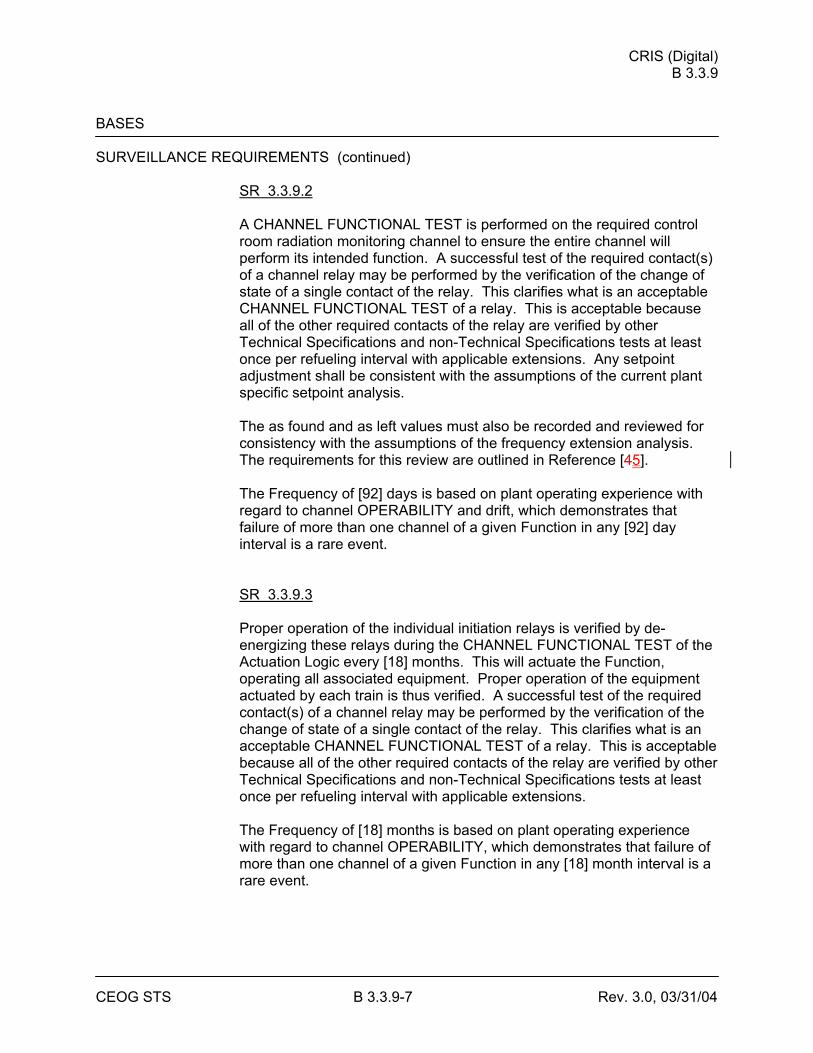
CRIS (Digital) B 3.3.9
CEOG STS B 3.3.9-7 Rev. 3.0, 03/31/04
BASES SURVEILLANCE REQUIREMENTS (continued)
SR 3.3.9.2 A CHANNEL FUNCTIONAL TEST is performed on the required control room radiation monitoring channel to ensure the entire channel will perform its intended function. A successful test of the required contact(s) of a channel relay may be performed by the verification of the change of state of a single contact of the relay. This clarifies what is an acceptable CHANNEL FUNCTIONAL TEST of a relay. This is acceptable because all of the other required contacts of the relay are verified by other Technical Specifications and non-Technical Specifications tests at least once per refueling interval with applicable extensions. Any setpoint adjustment shall be consistent with the assumptions of the current plant specific setpoint analysis. The as found and as left values must also be recorded and reviewed for consistency with the assumptions of the frequency extension analysis. The requirements for this review are outlined in Reference [45]. The Frequency of [92] days is based on plant operating experience with regard to channel OPERABILITY and drift, which demonstrates that failure of more than one channel of a given Function in any [92] day interval is a rare event. SR 3.3.9.3 Proper operation of the individual initiation relays is verified by de-energizing these relays during the CHANNEL FUNCTIONAL TEST of the Actuation Logic every [18] months. This will actuate the Function, operating all associated equipment. Proper operation of the equipment actuated by each train is thus verified. A successful test of the required contact(s) of a channel relay may be performed by the verification of the change of state of a single contact of the relay. This clarifies what is an acceptable CHANNEL FUNCTIONAL TEST of a relay. This is acceptable because all of the other required contacts of the relay are verified by other Technical Specifications and non-Technical Specifications tests at least once per refueling interval with applicable extensions. The Frequency of [18] months is based on plant operating experience with regard to channel OPERABILITY, which demonstrates that failure of more than one channel of a given Function in any [18] month interval is a rare event.

CRIS (Digital) B 3.3.9
CEOG STS B 3.3.9-8 Rev. 3.0, 03/31/04
BASES SURVEILLANCE REQUIREMENTS (continued)
Note 1 indicates this Surveillance includes verification of operation for each initiation relay. Note 2 indicates that relays that cannot be tested at power are excepted from the Surveillance Requirement while at power. These relays must, however, be tested during each entry into MODE 5 exceeding 24 hours unless they have been tested within the previous 6 months. SR 3.3.9.4 CHANNEL CALIBRATION is a complete check of the instrument channel including the sensor. The Surveillance verifies that the channel responds to a measured parameter within the necessary range and accuracy. CHANNEL CALIBRATION leaves the channel adjusted to account for instrument drift between successive calibrations to ensure that the channel remains operational between successive surveillances. CHANNEL CALIBRATIONS must be performed consistent with the plant specific setpoint analysis. The as found and as left values must also be recorded and reviewed for consistency with the assumptions of the surveillance interval extension analysis. The requirements for this review are outlined in Reference [45]. The Frequency is based upon the assumption of an [18] month calibration interval for the determination of the magnitude of equipment drift in the setpoint analysis. SR 3.3.9.5 Every [18] months, a CHANNEL FUNCTIONAL TEST is performed on the manual CRIS actuation circuitry. A successful test of the required contact(s) of a channel relay may be performed by the verification of the change of state of a single contact of the relay. This clarifies what is an acceptable CHANNEL FUNCTIONAL TEST of a relay. This is acceptable because all of the other required contacts of the relay are verified by other Technical Specifications and non-Technical Specifications tests at least once per refueling interval with applicable extensions.
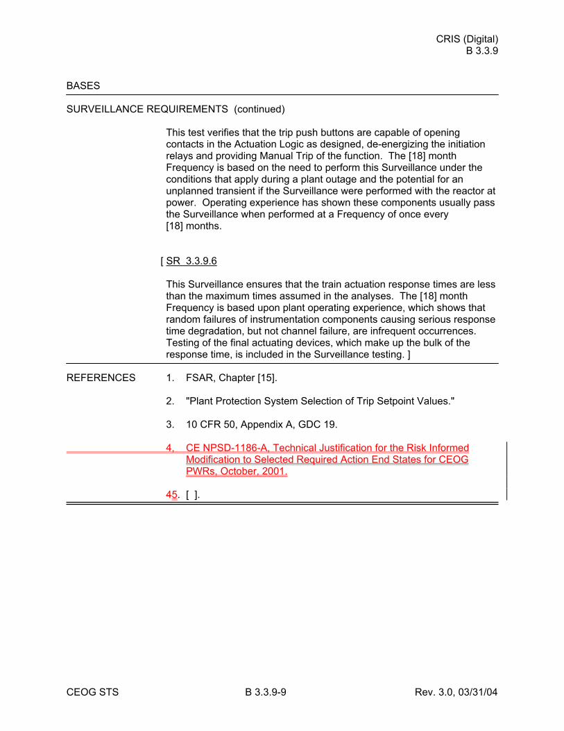
CRIS (Digital) B 3.3.9
CEOG STS B 3.3.9-9 Rev. 3.0, 03/31/04
BASES SURVEILLANCE REQUIREMENTS (continued)
This test verifies that the trip push buttons are capable of opening contacts in the Actuation Logic as designed, de-energizing the initiation relays and providing Manual Trip of the function. The [18] month Frequency is based on the need to perform this Surveillance under the conditions that apply during a plant outage and the potential for an unplanned transient if the Surveillance were performed with the reactor at power. Operating experience has shown these components usually pass the Surveillance when performed at a Frequency of once every [18] months.
[ SR 3.3.9.6 This Surveillance ensures that the train actuation response times are less than the maximum times assumed in the analyses. The [18] month Frequency is based upon plant operating experience, which shows that random failures of instrumentation components causing serious response time degradation, but not channel failure, are infrequent occurrences. Testing of the final actuating devices, which make up the bulk of the response time, is included in the Surveillance testing. ]
REFERENCES 1. FSAR, Chapter [15]. 2. "Plant Protection System Selection of Trip Setpoint Values." 3. 10 CFR 50, Appendix A, GDC 19. 4, CE NPSD-1186-A, Technical Justification for the Risk Informed
Modification to Selected Required Action End States for CEOG PWRs, October, 2001.
45. [ ].
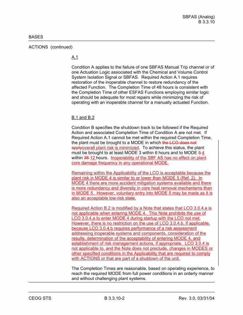
SBFAS (Analog) B 3.3.10
CEOG STS B 3.3.10-2 Rev. 3.0, 03/31/04
BASES ACTIONS (continued)
A.1
Condition A applies to the failure of one SBFAS Manual Trip channel or of one Actuation Logic associated with the Chemical and Volume Control System Isolation Signal or SBFAS. Required Action A.1 requires restoration of the inoperable channel to restore redundancy of the affected Function. The Completion Time of 48 hours is consistent with the Completion Time of other ESFAS Functions employing similar logic and should be adequate for most repairs while minimizing the risk of operating with an inoperable channel for a manually actuated Function. B.1 and B.2 Condition B specifies the shutdown track to be followed if the Required Action and associated Completion Time of Condition A are not met. If Required Action A.1 cannot be met within the required Completion Time, the plant must be brought to a MODE in which the LCO does not applyoverall plant risk is minimized. To achieve this status, the plant must be brought to at least MODE 3 within 6 hours and to MODE 5 4 within 36 12 hours. Inoperability of the SBF AS has no effect on plant core damage frequency in any operational MODE. Remaining within the Applicability of the LCO is acceptable because the plant risk in MODE 4 is similar to or lower than MODE 5 (Ref. 2). In MODE 4 there are more accident mitigation systems available and there is more redundancy and diversity in core heat removal mechanisms than in MODE 5. However, voluntary entry into MODE 5 may be made as it is also an acceptable low-risk state. Required Action B.2 is modified by a Note that states that LCO 3.0.4.a is not applicable when entering MODE 4. This Note prohibits the use of LCO 3.0.4.a to enter MODE 4 during startup with the LCO not met. However, there is no restriction on the use of LCO 3.0.4.b, if applicable, because LCO 3.0.4.b requires performance of a risk assessment addressing inoperable systems and components, consideration of the results, determination of the acceptability of entering MODE 4, and establishment of risk management actions, if appropriate. LCO 3.0.4 is not applicable to, and the Note does not preclude, changes in MODES or other specified conditions in the Applicability that are required to comply with ACTIONS or that are part of a shutdown of the unit. The Completion Times are reasonable, based on operating experience, to reach the required MODE from full power conditions in an orderly manner and without challenging plant systems.
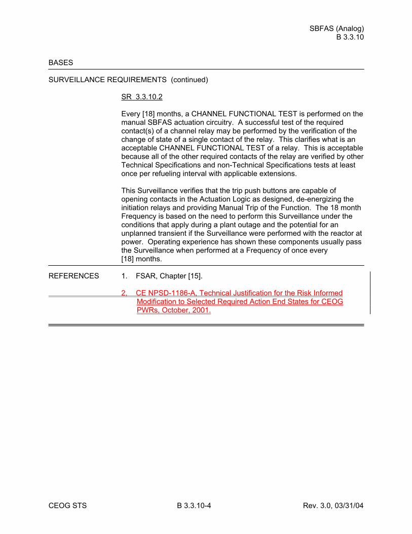
SBFAS (Analog) B 3.3.10
CEOG STS B 3.3.10-4 Rev. 3.0, 03/31/04
BASES SURVEILLANCE REQUIREMENTS (continued)
SR 3.3.10.2 Every [18] months, a CHANNEL FUNCTIONAL TEST is performed on the manual SBFAS actuation circuitry. A successful test of the required contact(s) of a channel relay may be performed by the verification of the change of state of a single contact of the relay. This clarifies what is an acceptable CHANNEL FUNCTIONAL TEST of a relay. This is acceptable because all of the other required contacts of the relay are verified by other Technical Specifications and non-Technical Specifications tests at least once per refueling interval with applicable extensions. This Surveillance verifies that the trip push buttons are capable of opening contacts in the Actuation Logic as designed, de-energizing the initiation relays and providing Manual Trip of the Function. The 18 month Frequency is based on the need to perform this Surveillance under the conditions that apply during a plant outage and the potential for an unplanned transient if the Surveillance were performed with the reactor at power. Operating experience has shown these components usually pass the Surveillance when performed at a Frequency of once every [18] months.
REFERENCES 1. FSAR, Chapter [15]. 2, CE NPSD-1186-A, Technical Justification for the Risk Informed
Modification to Selected Required Action End States for CEOG PWRs, October, 2001.
RCS Loops - MODE 4 B 3.4.6
CEOG STS B 3.4.6-3 Rev. 3.1, 12/01/05
BASES APPLICABILITY In MODE 4, this LCO applies because it is possible to remove core decay
heat and to provide proper boron mixing with either the RCS loops and SGs or the SDC System. Operation in other MODES is covered by: LCO 3.4.4, "RCS Loops - MODES 1 and 2," LCO 3.4.5, "RCS Loops - MODE 3," LCO 3.4.7, "RCS Loops - MODE 5, Loops Filled," LCO 3.4.8, "RCS Loops - MODE 5, Loops Not Filled," LCO 3.9.4, "Shutdown Cooling and Coolant Circulation - High Water Level" (MODE 6), and LCO 3.9.5, "Shutdown Cooling and Coolant Circulation - Low Water Level" (MODE 6).
ACTIONS A.1
If only one required RCS loop is OPERABLE and in operation and no SDC trains are OPERABLE, redundancy for heat removal is lost. Action must be initiated immediately to restore a required non-operating loop or train to OPERABLE status. The immediate Completion Time reflects the importance of maintaining the availability of two paths for decay heat removal. A.2 If restoration is not accomplished and a SDC train is OPERABLE, the plant must be placed in MODE 5 within the next 24 hours. Placing the plant in MODE 5 is a conservative action with regard to decay heat removal. With only one SDC train OPERABLE, redundancy for decay heat removal is lost and, in the event of a loss of the remaining SDC train, it would be safer to initiate that loss from MODE 5 rather than MODE 4. The Completion Time of 24 hours is reasonable, based on operating experience, to reach MODE 5 from MODE 4, with only one SDC train operating, in an orderly manner and without challenging plant systems. This Required Action is modified by a Note which indicates that the unit must be placed in MODE 5 only if a SDC train is OPERABLE. With no SDC train OPERABLE, the unit is in a condition with only limited cooldown capabilities. Therefore, the actions are to be concentrated on the restoration of a SDC train, rather than a cooldown of extended duration. If only one required SDC train is OPERABLE and in operation and no required RCS loops are OPERABLE, redundancy for heat removal is lost and the plant must be placed in a configuration that minimizes overall plant risk. This redundancy is obtained by making at least one SG available for decay heat removal via natural circulation because:
RCS Loops - MODE 4 B 3.4.6
CEOG STS B 3.4.6-4 Rev. 3.1, 12/01/05
1. MODE 4 operation poses overall lower risk of core damage and large
early radiation release than does MODE 5 (Ref. 1). This is particularly true with SDC impaired.
2. In MODE 4, RCS and steam generator conditions may be maintained
such that failure of the operating SDC train may be mitigated by natural circulation heat removal through one or more steam generators.
Remaining within the Applicability of the LCO is acceptable because the plant risk in MODE 4 is similar to or lower than MODE 5 (Ref. 1). However, voluntary entry into MODE 5 may be made as it is also an acceptable low-risk state. Required Action A.2 is modified by a Note that states that LCO 3.0.4.a is not applicable when entering MODE 4. This Note prohibits the use of LCO 3.0.4.a to enter MODE 4 during startup with the LCO not met. However, there is no restriction on the use of LCO 3.0.4.b, if applicable, because LCO 3.0.4.b requires performance of a risk assessment addressing inoperable systems and components, consideration of the results, determination of the acceptability of entering MODE 4, and establishment of risk management actions, if appropriate. LCO 3.0.4 is not applicable to, and the Note does not preclude, changes in MODES or other specified conditions in the Applicability that are required to comply with ACTIONS or that are part of a shutdown of the unit.
RCS Loops - MODE 4 B 3.4.6
CEOG STS B 3.4.6-6 Rev. 3.1, 12/01/05
BASES SURVEILLANCE REQUIREMENTS (continued)
SR 3.4.6.3 Verification that each required pump is OPERABLE ensures that an additional RCS loop or SDC train can be placed in operation, if needed to maintain decay heat removal and reactor coolant circulation. Verification is performed by verifying proper breaker alignment and power available to each required pump. Alternatively, verification that a pump is in operation also verifies proper breaker alignment and power availability. The Frequency of 7 days is considered reasonable in view of other administrative controls available and has been shown to be acceptable by operating experience. This SR is modified by a Note that states the SR is not required to be performed until 24 hours after a required pump is not in operation.
REFERENCES None1. CE NPSD-1186-A, Technical Justification for the Risk Informed
Modification to Selected Required Action End States for CEOG PWRs, October, 2001.
RWT B 3.5.4
CEOG STS B 3.5.4-4 Rev. 3.0, 03/31/04
BASES APPLICABILITY In MODES 1, 2, 3, and 4, the RWT OPERABILITY requirements are
dictated by the ECCS and Containment Spray System OPERABILITY requirements. Since both the ECCS and the Containment Spray System must be OPERABLE in MODES 1, 2, 3, and 4, the RWT must be OPERABLE to support their operation. Core cooling requirements in MODE 5 are addressed by LCO 3.4.7, "RCS Loops - MODE 5, Loops Filled," and LCO 3.4.8, "RCS Loops - MODE 5, Loops Not Filled." MODE 6 core cooling requirements are addressed by LCO 3.9.4, "Shutdown Cooling (SDC) and Coolant Circulation - High Water Level," and LCO 3.9.5, "Shutdown Cooling (SDC) and Coolant Circulation - Low Water Level."
ACTIONS A.1
With RWT boron concentration or borated water temperature not within limits, it must be returned to within limits within 8 hours. In this condition neither the ECCS nor the Containment Spray System can perform their design functions; therefore, prompt action must be taken to restore the tank to OPERABLE condition. The allowed Completion Time of 8 hours to restore the RWT to within limits was developed considering the time required to change boron concentration or temperature and that the contents of the tank are still available for injection. B.1 If the R WT boron concentration is not restored to within limits within the associated Completion Time, the plant must be brought to MODE 3 within 6 hours. The allowed Completion Time of 6 hours is reasonable, based on operating experience, to reach the required plant conditions from full power conditions in an orderly manner and without challenging plant systems. Reference 2 demonstrated that is it acceptable to remain in MODE 3 in this condition because the boron concentration limit is based on MODE 1 events which are unlikely in MODE 3, such as a LOCA, and conditions which do not exist in MODE 3, such as a critical core with all rods out. Since the anticipated deviations from the R WT boron concentration requirements are expected to be small and the ability to correct the deficiency is expected to be readily available, entry into MODE 4 or 5 is not unnecessary. Required Action B.1 is modified by a Note that states that LCO 3.0.4.a is not applicable when entering MODE 3 or MODE 4. This Note prohibits the use of LCO 3.0.4.a to enter MODE 3 or MODE 4 during startup with the LCO not met. However, there is no restriction on the use of LCO 3.0.4.b, if applicable, because LCO 3.0.4.b requires performance of a risk assessment addressing inoperable systems and components, consideration of the results, determination of the acceptability of entering MODE 4, and establishment of risk management actions, if appropriate.
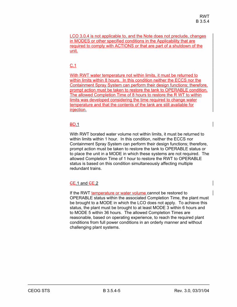
RWT B 3.5.4
CEOG STS B 3.5.4-5 Rev. 3.0, 03/31/04
LCO 3.0.4 is not applicable to, and the Note does not preclude, changes in MODES or other specified conditions in the Applicability that are required to comply with ACTIONS or that are part of a shutdown of the unit. C.1 With RWT water temperature not within limits, it must be returned to within limits within 8 hours. In this condition neither the ECCS nor the Containment Spray System can perform their design functions; therefore, prompt action must be taken to restore the tank to OPERABLE condition. The allowed Completion Time of 8 hours to restore the R WT to within limits was developed considering the time required to change water temperature and that the contents of the tank are still available for injection. BD.1 With RWT borated water volume not within limits, it must be returned to within limits within 1 hour. In this condition, neither the ECCS nor Containment Spray System can perform their design functions; therefore, prompt action must be taken to restore the tank to OPERABLE status or to place the unit in a MODE in which these systems are not required. The allowed Completion Time of 1 hour to restore the RWT to OPERABLE status is based on this condition simultaneously affecting multiple redundant trains. CE.1 and CE.2 If the RWT temperature or water volume cannot be restored to OPERABLE status within the associated Completion Time, the plant must be brought to a MODE in which the LCO does not apply. To achieve this status, the plant must be brought to at least MODE 3 within 6 hours and to MODE 5 within 36 hours. The allowed Completion Times are reasonable, based on operating experience, to reach the required plant conditions from full power conditions in an orderly manner and without challenging plant systems.
RWT B 3.5.4
CEOG STS B 3.5.4-6 Rev. 3.0, 03/31/04
BASES SURVEILLANCE SR 3.5.4.1 REQUIREMENTS
RWT borated water temperature shall be verified every 24 hours to be within the limits assumed in the accident analysis. This Frequency has been shown to be sufficient to identify temperature changes that approach either acceptable limit. The SR is modified by a Note that eliminates the requirement to perform this Surveillance when ambient air temperatures are within the operating temperature limits of the RWT. With ambient temperatures within this range, the RWT temperature should not exceed the limits. SR 3.5.4.2 Above minimum RWT water volume level shall be verified every 7 days. This Frequency ensures that a sufficient initial water supply is available for injection and to support continued ESF pump operation on recirculation. Since the RWT volume is normally stable and is provided with a Low Level Alarm, a 7 day Frequency is appropriate and has been shown to be acceptable through operating experience. SR 3.5.4.3 Boron concentration of the RWT shall be verified every 7 days to be within the required range. This Frequency ensures that the reactor will remain subcritical following a LOCA. Further, it ensures that the resulting sump pH will be maintained in an acceptable range such that boron precipitation in the core will not occur earlier than predicted and the effect of chloride and caustic stress corrosion on mechanical systems and components will be minimized. Since the RWT volume is normally stable, a 7 day sampling Frequency is appropriate and has been shown through operating experience to be acceptable.
REFERENCES 1. FSAR, Chapter [6] and Chapter [15]. 2. CE NPSD-1186-A, Technical Justification for the Risk Informed
Modification to Selected Required Action End States for CEOG PWRs, October, 2001.
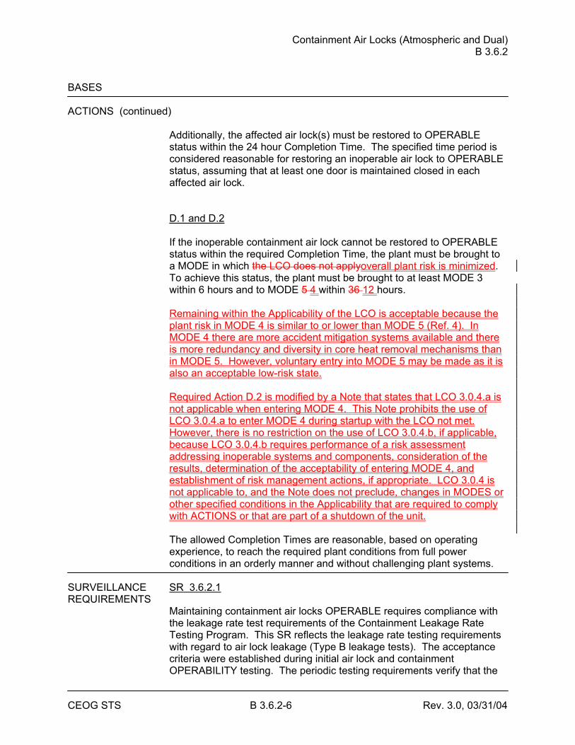
Containment Air Locks (Atmospheric and Dual) B 3.6.2
CEOG STS B 3.6.2-6 Rev. 3.0, 03/31/04
BASES ACTIONS (continued)
Additionally, the affected air lock(s) must be restored to OPERABLE status within the 24 hour Completion Time. The specified time period is considered reasonable for restoring an inoperable air lock to OPERABLE status, assuming that at least one door is maintained closed in each affected air lock. D.1 and D.2 If the inoperable containment air lock cannot be restored to OPERABLE status within the required Completion Time, the plant must be brought to a MODE in which the LCO does not applyoverall plant risk is minimized. To achieve this status, the plant must be brought to at least MODE 3 within 6 hours and to MODE 5 4 within 36 12 hours. Remaining within the Applicability of the LCO is acceptable because the plant risk in MODE 4 is similar to or lower than MODE 5 (Ref. 4). In MODE 4 there are more accident mitigation systems available and there is more redundancy and diversity in core heat removal mechanisms than in MODE 5. However, voluntary entry into MODE 5 may be made as it is also an acceptable low-risk state. Required Action D.2 is modified by a Note that states that LCO 3.0.4.a is not applicable when entering MODE 4. This Note prohibits the use of LCO 3.0.4.a to enter MODE 4 during startup with the LCO not met. However, there is no restriction on the use of LCO 3.0.4.b, if applicable, because LCO 3.0.4.b requires performance of a risk assessment addressing inoperable systems and components, consideration of the results, determination of the acceptability of entering MODE 4, and establishment of risk management actions, if appropriate. LCO 3.0.4 is not applicable to, and the Note does not preclude, changes in MODES or other specified conditions in the Applicability that are required to comply with ACTIONS or that are part of a shutdown of the unit. The allowed Completion Times are reasonable, based on operating experience, to reach the required plant conditions from full power conditions in an orderly manner and without challenging plant systems.
SURVEILLANCE SR 3.6.2.1 REQUIREMENTS
Maintaining containment air locks OPERABLE requires compliance with the leakage rate test requirements of the Containment Leakage Rate Testing Program. This SR reflects the leakage rate testing requirements with regard to air lock leakage (Type B leakage tests). The acceptance criteria were established during initial air lock and containment OPERABILITY testing. The periodic testing requirements verify that the
Containment Air Locks (Atmospheric and Dual) B 3.6.2
CEOG STS B 3.6.2-8 Rev. 3.0, 03/31/04
BASES SURVEILLANCE REQUIREMENTS (continued)
SR 3.6.2.2 The air lock interlock is designed to prevent simultaneous opening of both doors in a single air lock. Since both the inner and outer doors of an air lock are designed to withstand the maximum expected post accident containment pressure, closure of either door will support containment OPERABILITY. Thus, the door interlock feature supports containment OPERABILITY while the air lock is being used for personnel transit into and out of containment. Periodic testing of this interlock demonstrates that the interlock will function as designed and that simultaneous opening of the inner and outer doors will not inadvertently occur. Due to the purely mechanical nature of this interlock, and given that the interlock mechanism is not normally challenged when the containment airlock door is used for entry and exit (procedures require strict adherence to single door opening), this test is only required to be performed every 24 months. The 24 month Frequency is based on the need to perform this Surveillance under the conditions that apply during a plant outage, and the potential for loss of containment OPERABILITY if the Surveillance were performed with the reactor at power. The 24 month Frequency for the interlock is justified based on generic operating experience. The 24 month Frequency is based on engineering judgment and is considered adequate given that the interlock is not challenged during the use of the airlock.
REFERENCES 1. 10 CFR 50, Appendix J, Option [A][B]. 2. FSAR, Section [ ]. 3. FSAR, Section [ ]. 4. CE NPSD-1186-A, Technical Justification for the Risk Informed
Modification to Selected Required Action End States for CEOG PWRs, October, 2001.
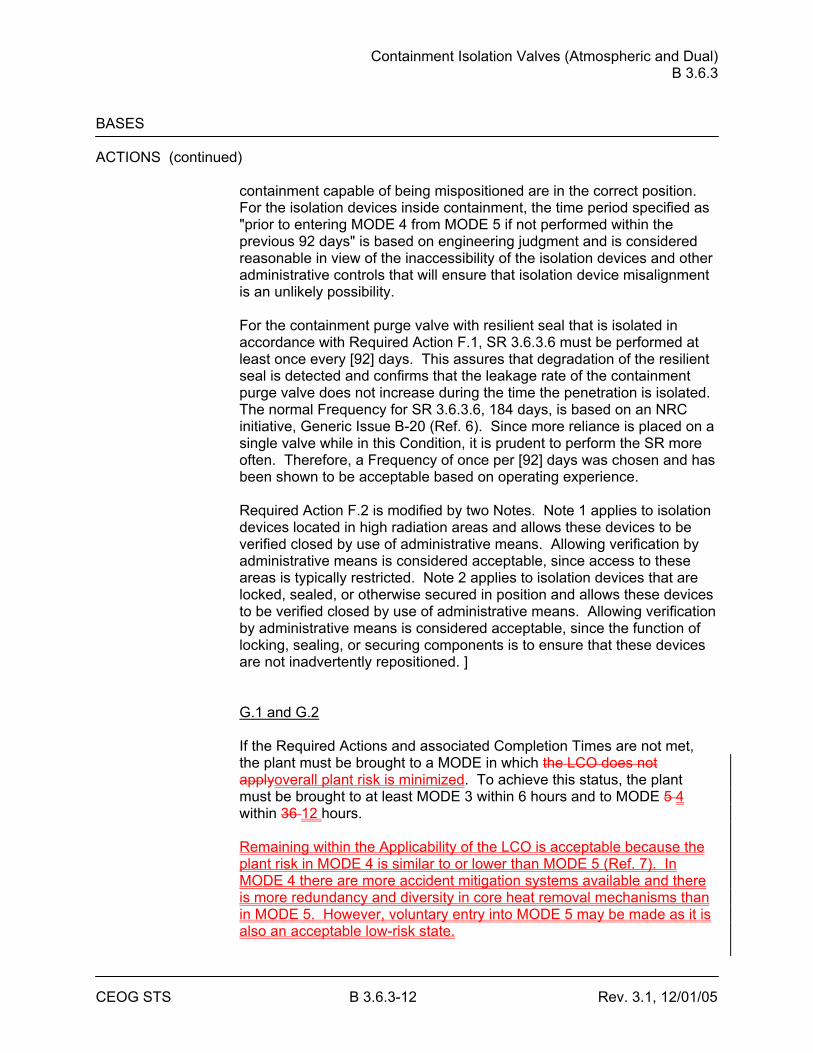
Containment Isolation Valves (Atmospheric and Dual) B 3.6.3
CEOG STS B 3.6.3-12 Rev. 3.1, 12/01/05
BASES ACTIONS (continued)
containment capable of being mispositioned are in the correct position. For the isolation devices inside containment, the time period specified as "prior to entering MODE 4 from MODE 5 if not performed within the previous 92 days" is based on engineering judgment and is considered reasonable in view of the inaccessibility of the isolation devices and other administrative controls that will ensure that isolation device misalignment is an unlikely possibility. For the containment purge valve with resilient seal that is isolated in accordance with Required Action F.1, SR 3.6.3.6 must be performed at least once every [92] days. This assures that degradation of the resilient seal is detected and confirms that the leakage rate of the containment purge valve does not increase during the time the penetration is isolated. The normal Frequency for SR 3.6.3.6, 184 days, is based on an NRC initiative, Generic Issue B-20 (Ref. 6). Since more reliance is placed on a single valve while in this Condition, it is prudent to perform the SR more often. Therefore, a Frequency of once per [92] days was chosen and has been shown to be acceptable based on operating experience. Required Action F.2 is modified by two Notes. Note 1 applies to isolation devices located in high radiation areas and allows these devices to be verified closed by use of administrative means. Allowing verification by administrative means is considered acceptable, since access to these areas is typically restricted. Note 2 applies to isolation devices that are locked, sealed, or otherwise secured in position and allows these devices to be verified closed by use of administrative means. Allowing verification by administrative means is considered acceptable, since the function of locking, sealing, or securing components is to ensure that these devices are not inadvertently repositioned. ] G.1 and G.2 If the Required Actions and associated Completion Times are not met, the plant must be brought to a MODE in which the LCO does not applyoverall plant risk is minimized. To achieve this status, the plant must be brought to at least MODE 3 within 6 hours and to MODE 5 4 within 36 12 hours. Remaining within the Applicability of the LCO is acceptable because the plant risk in MODE 4 is similar to or lower than MODE 5 (Ref. 7). In MODE 4 there are more accident mitigation systems available and there is more redundancy and diversity in core heat removal mechanisms than in MODE 5. However, voluntary entry into MODE 5 may be made as it is also an acceptable low-risk state.
Containment Isolation Valves (Atmospheric and Dual) B 3.6.3
CEOG STS B 3.6.3-13 Rev. 3.1, 12/01/05
Required Action G.2 is modified by a Note that states that LCO 3.0.4.a is not applicable when entering MODE 4. This Note prohibits the use of LCO 3.0.4.a to enter MODE 4 during startup with the LCO not met. However, there is no restriction on the use of LCO 3.0.4.b, if applicable, because LCO 3.0.4.b requires performance of a risk assessment addressing inoperable systems and components, consideration of the results, determination of the acceptability of entering MODE 4, and establishment of risk management actions, if appropriate. LCO 3.0.4 is not applicable to, and the Note does not preclude, changes in MODES or other specified conditions in the Applicability that are required to comply with ACTIONS or that are part of a shutdown of the unit. The allowed Completion Times are reasonable, based on operating experience, to reach the required plant conditions from full power conditions in an orderly manner and without challenging plant systems.
Containment Isolation Valves (Atmospheric and Dual) B 3.6.3
CEOG STS B 3.6.3-14 Rev. 3.1, 12/01/05
BASES SURVEILLANCE [ SR 3.6.3.1 REQUIREMENTS
Each [42] inch containment purge valve is required to be verified sealed closed at 31 day intervals. This Surveillance is designed to ensure that a gross breach of containment is not caused by an inadvertent or spurious opening of a containment purge valve. Detailed analysis of the purge valves failed to conclusively demonstrate their ability to close during a LOCA in time to limit offsite doses. Therefore, these valves are required to be in the sealed closed position during MODES 1, 2, 3, and 4. A containment purge valve that is sealed closed must have motive power to the valve operator removed. This can be accomplished by de-energizing the source of electric power or by removing the air supply to the valve operator. In this application, the term "sealed" has no connotation of leak tightness. The Frequency is a result of an NRC initiative, Generic Issue B-24 (Ref. 78), related to containment purge valve use during unit operations. This SR is not required to be met while in Condition E of this LCO. This is reasonable since the penetration flow path would be isolated. ] SR 3.6.3.2 This SR ensures that the minipurge valves are closed as required or, if open, open for an allowable reason. If a purge valve is open in violation of this SR, the valve is considered inoperable. If the inoperable valve is not otherwise known to have excessive leakage when closed, it is not considered to have leakage outside of limits. The SR is not required to be met when the purge valves are open for pressure control, ALARA or air quality considerations for personnel entry, or for Surveillances that require the valves to be open. The minipurge valves are capable of closing in the environment following a LOCA. Therefore, these valves are allowed to be open for limited periods of time. The 31 day Frequency is consistent with other containment isolation valve requirements discussed in SR 3.6.3.3. SR 3.6.3.3 This SR requires verification that each containment isolation manual valve and blind flange located outside containment and not locked, sealed, or otherwise secured and required to be closed during accident conditions is closed. The SR helps to ensure that post accident leakage of radioactive fluids or gases outside the containment boundary is within design limits. This SR does not require any testing or valve manipulation. Rather, it involves verification that those containment isolation valves outside containment and capable of being mispositioned are in the correct
Containment Isolation Valves (Atmospheric and Dual) B 3.6.3
CEOG STS B 3.6.3-16 Rev. 3.1, 12/01/05
BASES SURVEILLANCE REQUIREMENTS (continued)
SR 3.6.3.5 Verifying that the isolation time of each automatic power operated containment isolation valve is within limits is required to demonstrate OPERABILITY. The isolation time test ensures the valve will isolate in a time period less than or equal to that assumed in the safety analysis. [The isolation time and Frequency of this SR are in accordance with the Inservice Testing Program or 92 days.] SR 3.6.3.6 For containment purge valves with resilient seals, additional leakage rate testing beyond the test requirements of 10 CFR 50, Appendix J, Option [A][B], (Ref. 89), is required to ensure OPERABILITY. Operating experience has demonstrated that this type of seal has the potential to degrade in a shorter time period than do other seal types. Based on this observation and the importance of maintaining this penetration leak tight (due to the direct path between containment and the environment), a Frequency of 184 days was established as part of the NRC resolution of Generic Issue B-20, "Containment Leakage Due to Seal Deterioration" (Ref. 6). Additionally, this SR must be performed within 92 days after opening the valve. The 92 day Frequency was chosen recognizing that cycling the valve could introduce additional seal degradation (beyond that occurring to a valve that has not been opened). Thus, decreasing the interval (from 184 days) is a prudent measure after a valve has been opened. SR 3.6.3.7 Automatic containment isolation valves close on a containment isolation signal to prevent leakage of radioactive material from containment following a DBA. This SR ensures each automatic containment isolation valve will actuate to its isolation position on a containment isolation actuation signal. This Surveillance is not required for valves that are locked, sealed, or otherwise secured in the required position under administrative controls. The [18] month Frequency was developed considering it is prudent that this SR be performed only during a unit outage, since isolation of penetrations would eliminate cooling water flow and disrupt normal operation of many critical components. Operating experience has shown that these components usually pass this SR when performed on the [18] month Frequency. Therefore, the Frequency was concluded to be acceptable from a reliability standpoint.
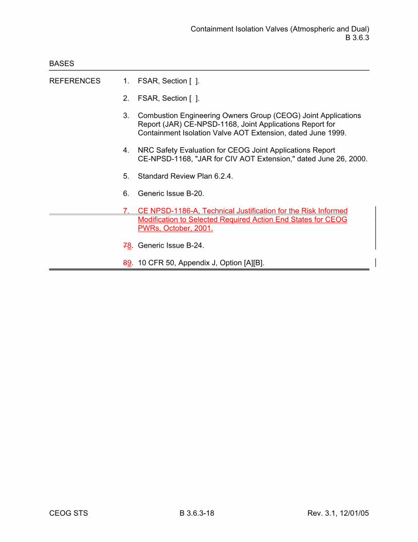
Containment Isolation Valves (Atmospheric and Dual) B 3.6.3
CEOG STS B 3.6.3-18 Rev. 3.1, 12/01/05
BASES REFERENCES 1. FSAR, Section [ ]. 2. FSAR, Section [ ]. 3. Combustion Engineering Owners Group (CEOG) Joint Applications
Report (JAR) CE-NPSD-1168, Joint Applications Report for Containment Isolation Valve AOT Extension, dated June 1999.
4. NRC Safety Evaluation for CEOG Joint Applications Report
CE-NPSD-1168, "JAR for CIV AOT Extension," dated June 26, 2000. 5. Standard Review Plan 6.2.4. 6. Generic Issue B-20. 7. CE NPSD-1186-A, Technical Justification for the Risk Informed
Modification to Selected Required Action End States for CEOG PWRs, October, 2001.
78. Generic Issue B-24. 89. 10 CFR 50, Appendix J, Option [A][B].
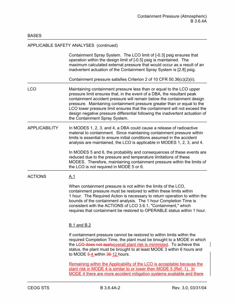
Containment Pressure (Atmospheric) B 3.6.4A
CEOG STS B 3.6.4A-2 Rev. 3.0, 03/31/04
BASES APPLICABLE SAFETY ANALYSES (continued)
Containment Spray System. The LCO limit of [-0.3] psig ensures that operation within the design limit of [-0.5] psig is maintained. The maximum calculated external pressure that would occur as a result of an inadvertent actuation of the Containment Spray System is [2.8] psig. Containment pressure satisfies Criterion 2 of 10 CFR 50.36(c)(2)(ii).
LCO Maintaining containment pressure less than or equal to the LCO upper
pressure limit ensures that, in the event of a DBA, the resultant peak containment accident pressure will remain below the containment design pressure. Maintaining containment pressure greater than or equal to the LCO lower pressure limit ensures that the containment will not exceed the design negative pressure differential following the inadvertent actuation of the Containment Spray System.
APPLICABILITY In MODES 1, 2, 3, and 4, a DBA could cause a release of radioactive
material to containment. Since maintaining containment pressure within limits is essential to ensure initial conditions assumed in the accident analysis are maintained, the LCO is applicable in MODES 1, 2, 3, and 4.
In MODES 5 and 6, the probability and consequences of these events are reduced due to the pressure and temperature limitations of these MODES. Therefore, maintaining containment pressure within the limits of the LCO is not required in MODE 5 or 6.
ACTIONS A.1
When containment pressure is not within the limits of the LCO, containment pressure must be restored to within these limits within 1 hour. The Required Action is necessary to return operation to within the bounds of the containment analysis. The 1 hour Completion Time is consistent with the ACTIONS of LCO 3.6.1, "Containment," which requires that containment be restored to OPERABLE status within 1 hour. B.1 and B.2 If containment pressure cannot be restored to within limits within the required Completion Time, the plant must be brought to a MODE in which the LCO does not applyoverall plant risk is minimized. To achieve this status, the plant must be brought to at least MODE 3 within 6 hours and to MODE 5 4 within 36 12 hours. Remaining within the Applicability of the LCO is acceptable because the plant risk in MODE 4 is similar to or lower than MODE 5 (Ref. 1). In MODE 4 there are more accident mitigation systems available and there
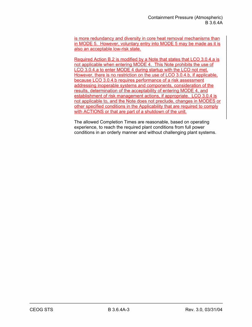
Containment Pressure (Atmospheric) B 3.6.4A
CEOG STS B 3.6.4A-3 Rev. 3.0, 03/31/04
is more redundancy and diversity in core heat removal mechanisms than in MODE 5. However, voluntary entry into MODE 5 may be made as it is also an acceptable low-risk state. Required Action B.2 is modified by a Note that states that LCO 3.0.4.a is not applicable when entering MODE 4. This Note prohibits the use of LCO 3.0.4.a to enter MODE 4 during startup with the LCO not met. However, there is no restriction on the use of LCO 3.0.4.b, if applicable, because LCO 3.0.4.b requires performance of a risk assessment addressing inoperable systems and components, consideration of the results, determination of the acceptability of entering MODE 4, and establishment of risk management actions, if appropriate. LCO 3.0.4 is not applicable to, and the Note does not preclude, changes in MODES or other specified conditions in the Applicability that are required to comply with ACTIONS or that are part of a shutdown of the unit. The allowed Completion Times are reasonable, based on operating experience, to reach the required plant conditions from full power conditions in an orderly manner and without challenging plant systems.
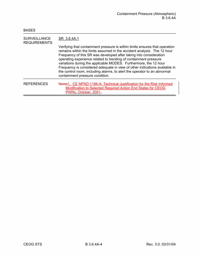
Containment Pressure (Atmospheric) B 3.6.4A
CEOG STS B 3.6.4A-4 Rev. 3.0, 03/31/04
BASES SURVEILLANCE SR 3.6.4A.1 REQUIREMENTS
Verifying that containment pressure is within limits ensures that operation remains within the limits assumed in the accident analysis. The 12 hour Frequency of this SR was developed after taking into consideration operating experience related to trending of containment pressure variations during the applicable MODES. Furthermore, the 12 hour Frequency is considered adequate in view of other indications available in the control room, including alarms, to alert the operator to an abnormal containment pressure condition.
REFERENCES None1. CE NPSD-1186-A, Technical Justification for the Risk Informed
Modification to Selected Required Action End States for CEOG PWRs, October, 2001..
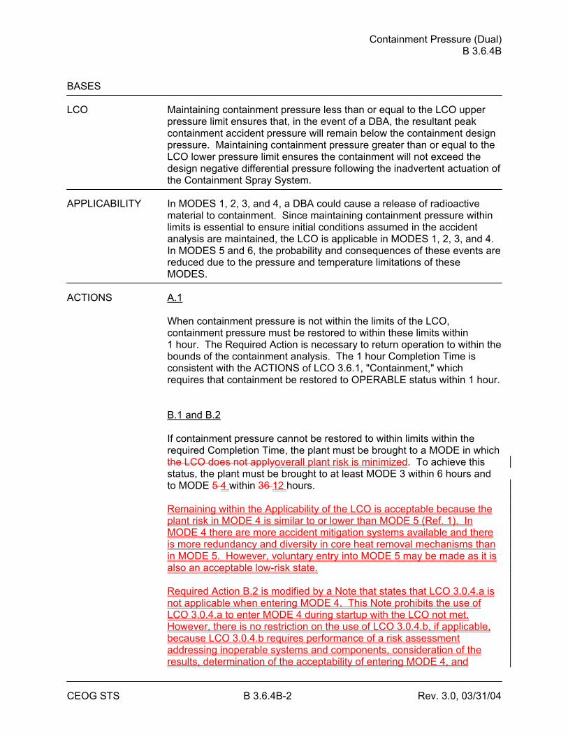
Containment Pressure (Dual) B 3.6.4B
CEOG STS B 3.6.4B-2 Rev. 3.0, 03/31/04
BASES LCO Maintaining containment pressure less than or equal to the LCO upper
pressure limit ensures that, in the event of a DBA, the resultant peak containment accident pressure will remain below the containment design pressure. Maintaining containment pressure greater than or equal to the LCO lower pressure limit ensures the containment will not exceed the design negative differential pressure following the inadvertent actuation of the Containment Spray System.
APPLICABILITY In MODES 1, 2, 3, and 4, a DBA could cause a release of radioactive
material to containment. Since maintaining containment pressure within limits is essential to ensure initial conditions assumed in the accident analysis are maintained, the LCO is applicable in MODES 1, 2, 3, and 4. In MODES 5 and 6, the probability and consequences of these events are reduced due to the pressure and temperature limitations of these MODES.
ACTIONS A.1
When containment pressure is not within the limits of the LCO, containment pressure must be restored to within these limits within 1 hour. The Required Action is necessary to return operation to within the bounds of the containment analysis. The 1 hour Completion Time is consistent with the ACTIONS of LCO 3.6.1, "Containment," which requires that containment be restored to OPERABLE status within 1 hour. B.1 and B.2
If containment pressure cannot be restored to within limits within the required Completion Time, the plant must be brought to a MODE in which the LCO does not applyoverall plant risk is minimized. To achieve this status, the plant must be brought to at least MODE 3 within 6 hours and to MODE 5 4 within 36 12 hours. Remaining within the Applicability of the LCO is acceptable because the plant risk in MODE 4 is similar to or lower than MODE 5 (Ref. 1). In MODE 4 there are more accident mitigation systems available and there is more redundancy and diversity in core heat removal mechanisms than in MODE 5. However, voluntary entry into MODE 5 may be made as it is also an acceptable low-risk state. Required Action B.2 is modified by a Note that states that LCO 3.0.4.a is not applicable when entering MODE 4. This Note prohibits the use of LCO 3.0.4.a to enter MODE 4 during startup with the LCO not met. However, there is no restriction on the use of LCO 3.0.4.b, if applicable, because LCO 3.0.4.b requires performance of a risk assessment addressing inoperable systems and components, consideration of the results, determination of the acceptability of entering MODE 4, and
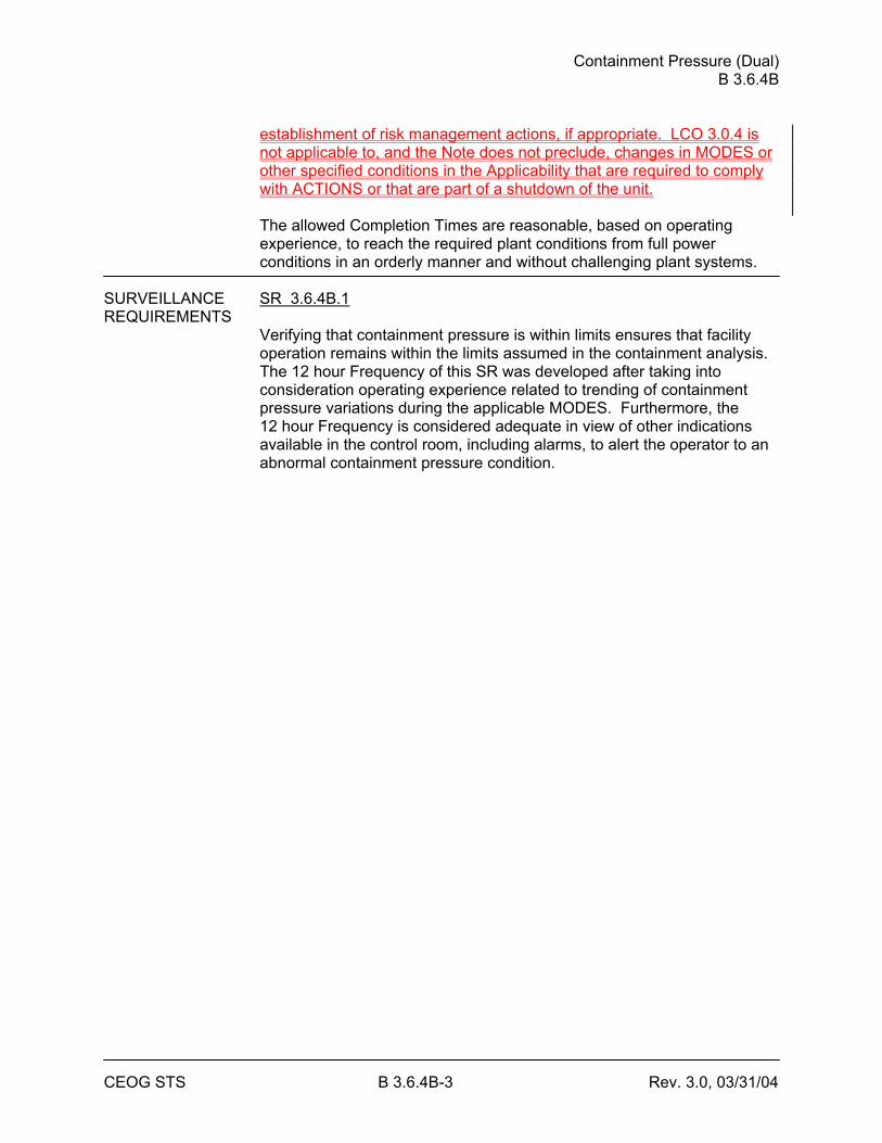
Containment Pressure (Dual) B 3.6.4B
CEOG STS B 3.6.4B-3 Rev. 3.0, 03/31/04
establishment of risk management actions, if appropriate. LCO 3.0.4 is not applicable to, and the Note does not preclude, changes in MODES or other specified conditions in the Applicability that are required to comply with ACTIONS or that are part of a shutdown of the unit. The allowed Completion Times are reasonable, based on operating experience, to reach the required plant conditions from full power conditions in an orderly manner and without challenging plant systems.
SURVEILLANCE SR 3.6.4B.1 REQUIREMENTS
Verifying that containment pressure is within limits ensures that facility operation remains within the limits assumed in the containment analysis. The 12 hour Frequency of this SR was developed after taking into consideration operating experience related to trending of containment pressure variations during the applicable MODES. Furthermore, the 12 hour Frequency is considered adequate in view of other indications available in the control room, including alarms, to alert the operator to an abnormal containment pressure condition.
Containment Pressure (Dual) B 3.6.4B
CEOG STS B 3.6.4B-4 Rev. 3.0, 03/31/04
BASES REFERENCES None1. CE NPSD-1186-A, Technical Justification for the Risk Informed
Modification to Selected Required Action End States for CEOG PWRs, October, 2001.
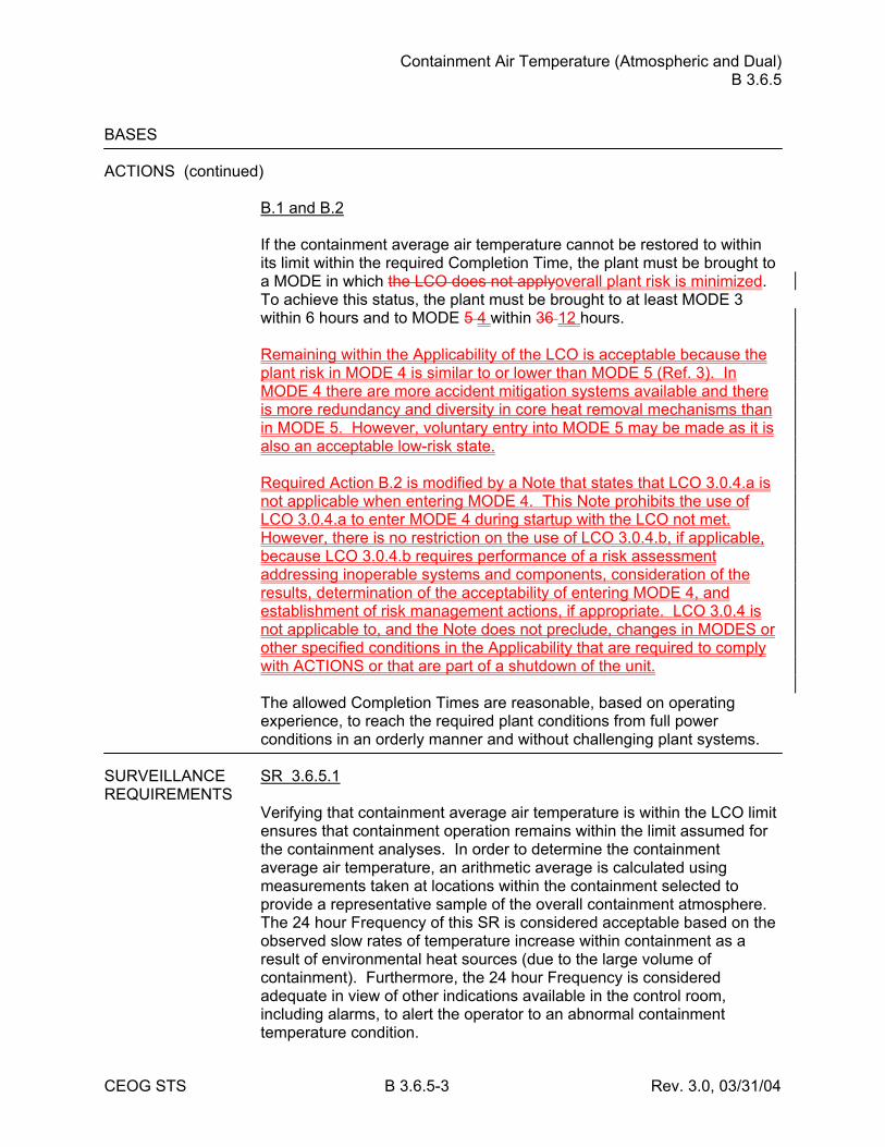
Containment Air Temperature (Atmospheric and Dual) B 3.6.5
CEOG STS B 3.6.5-3 Rev. 3.0, 03/31/04
BASES ACTIONS (continued)
B.1 and B.2 If the containment average air temperature cannot be restored to within its limit within the required Completion Time, the plant must be brought to a MODE in which the LCO does not applyoverall plant risk is minimized. To achieve this status, the plant must be brought to at least MODE 3 within 6 hours and to MODE 5 4 within 36 12 hours. Remaining within the Applicability of the LCO is acceptable because the plant risk in MODE 4 is similar to or lower than MODE 5 (Ref. 3). In MODE 4 there are more accident mitigation systems available and there is more redundancy and diversity in core heat removal mechanisms than in MODE 5. However, voluntary entry into MODE 5 may be made as it is also an acceptable low-risk state. Required Action B.2 is modified by a Note that states that LCO 3.0.4.a is not applicable when entering MODE 4. This Note prohibits the use of LCO 3.0.4.a to enter MODE 4 during startup with the LCO not met. However, there is no restriction on the use of LCO 3.0.4.b, if applicable, because LCO 3.0.4.b requires performance of a risk assessment addressing inoperable systems and components, consideration of the results, determination of the acceptability of entering MODE 4, and establishment of risk management actions, if appropriate. LCO 3.0.4 is not applicable to, and the Note does not preclude, changes in MODES or other specified conditions in the Applicability that are required to comply with ACTIONS or that are part of a shutdown of the unit. The allowed Completion Times are reasonable, based on operating experience, to reach the required plant conditions from full power conditions in an orderly manner and without challenging plant systems.
SURVEILLANCE SR 3.6.5.1 REQUIREMENTS
Verifying that containment average air temperature is within the LCO limit ensures that containment operation remains within the limit assumed for the containment analyses. In order to determine the containment average air temperature, an arithmetic average is calculated using measurements taken at locations within the containment selected to provide a representative sample of the overall containment atmosphere. The 24 hour Frequency of this SR is considered acceptable based on the observed slow rates of temperature increase within containment as a result of environmental heat sources (due to the large volume of containment). Furthermore, the 24 hour Frequency is considered adequate in view of other indications available in the control room, including alarms, to alert the operator to an abnormal containment temperature condition.
Containment Air Temperature (Atmospheric and Dual) B 3.6.5
CEOG STS B 3.6.5-4 Rev. 3.0, 03/31/04
REFERENCES 1. FSAR, Section [ ]. 2. FSAR, Section [ ]. 3. CE NPSD-1186-A, Technical Justification for the Risk Informed
Modification to Selected Required Action End States for CEOG PWRs, October, 2001.
Containment Spray and Cooling Systems (Atmospheric and Dual) B 3.6.6A
CEOG STS B 3.6.6A-5 Rev. 3.1, 12/01/05
BASES APPLICABILITY In MODES 1, 2, 3, and 4, a DBA could cause a release of radioactive
material to containment and an increase in containment pressure and temperature, requiring the operation of the containment spray trains and containment cooling trains.
In MODES 5 and 6, the probability and consequences of these events are reduced due to the pressure and temperature limitations of these MODES. Thus, the Containment Spray and Containment Cooling systems are not required to be OPERABLE in MODES 5 and 6.
ACTIONS A.1 -----------------------------------REVIEWER’S NOTE-----------------------------------
Utilization of the 7 day Completion Time for Required Action A.1 is dependent on the licensee adopting CE NPSD-1045-A (Ref. 6) and meeting the requirements of the Topical Report and the associated Safety Evaluation. Otherwise, a 72 hour Completion Time applies.
--------------------------------------------------------------------------------------------------
With one containment spray train inoperable, the inoperable containment spray train must be restored to OPERABLE status within [7] days. In this Condition, the remaining OPERABLE spray and cooling trains are adequate to perform the iodine removal and containment cooling functions. The [7] day Completion Time takes into account the redundant heat removal capability afforded by the Containment Spray System, reasonable time for repairs, and the findings of Ref. 6. B.1 and B.2 If the inoperable containment spray train cannot be restored to OPERABLE status within the required Completion Time, the plant must be brought to a MODE in which the LCO does not applyoverall plant risk is minimized. To achieve this status, the plant must be brought to at least MODE 3 within 6 hours and to MODE 5 4 within 84 hours. Remaining within the Applicability of the LCO is acceptable because the plant risk in MODE 4 is similar to or lower than MODE 5 (Ref. 6). In MODE 4 there are more accident mitigation systems available and there is more redundancy and diversity in core heat removal mechanisms than in MODE 5. However, voluntary entry into MODE 5 may be made as it is also an acceptable low-risk state. Required Action B.2 is modified by a Note that states that LCO 3.0.4.a is not applicable when entering MODE 4. This Note prohibits the use of LCO 3.0.4.a to enter MODE 4 during startup with the LCO not met. However, there is no restriction on the use of LCO 3.0.4.b, if applicable, because LCO 3.0.4.b requires performance of a risk assessment
Containment Spray and Cooling Systems (Atmospheric and Dual) B 3.6.6A
CEOG STS B 3.6.6A-6 Rev. 3.1, 12/01/05
addressing inoperable systems and components, consideration of the results, determination of the acceptability of entering MODE 4, and establishment of risk management actions, if appropriate. LCO 3.0.4 is not applicable to, and the Note does not preclude, changes in MODES or other specified conditions in the Applicability that are required to comply with ACTIONS or that are part of a shutdown of the unit. The allowed Completion Time of 6 hours is reasonable, based on operating experience, to reach MODE 3 from full power conditions in an orderly manner and without challenging plant systems. The extended interval to reach MODE 5 4 allows additional time for the restoration of the containment spray train and is reasonable when considering that the driving force for a release of radioactive material from the Reactor Coolant System is reduced in MODE 3.
Containment Spray and Cooling Systems (Atmospheric and Dual) B 3.6.6A
CEOG STS B 3.6.6A-8 Rev. 3.1, 12/01/05
BASES ACTIONS (continued)
F.1 and F.2 If the Required Actions and associated Completion Times of Condition C, D, or E of this LCO are not met, the plant must be brought to a MODE in which the LCO does not applyoverall plant risk is minimized. To achieve this status, the plant must be brought to at least MODE 3 within 6 hours and to MODE 5 4 within 36 12 hours. Remaining within the Applicability of the LCO is acceptable because the plant risk in MODE 4 is similar to or lower than MODE 5 (Ref. 6). In MODE 4 there are more accident mitigation systems available and there is more redundancy and diversity in core heat removal mechanisms than in MODE 5. However, voluntary entry into MODE 5 may be made as it is also an acceptable low-risk state. Required Action F.2 is modified by a Note that states that LCO 3.0.4.a is not applicable when entering MODE 4. This Note prohibits the use of LCO 3.0.4.a to enter MODE 4 during startup with the LCO not met. However, there is no restriction on the use of LCO 3.0.4.b, if applicable, because LCO 3.0.4.b requires performance of a risk assessment addressing inoperable systems and components, consideration of the results, determination of the acceptability of entering MODE 4, and establishment of risk management actions, if appropriate. LCO 3.0.4 is not applicable to, and the Note does not preclude, changes in MODES or other specified conditions in the Applicability that are required to comply with ACTIONS or that are part of a shutdown of the unit. The allowed Completion Times are reasonable, based on operating experience, to reach the required plant conditions from full power conditions in an orderly manner and without challenging plant systems. G.1 With two containment spray trains or any combination of three or more Containment Spray System and Containment Cooling System trains inoperable, the unit is in a condition outside the accident analysis. Therefore, LCO 3.0.3 must be entered immediately.
SURVEILLANCE SR 3.6.6A.1 REQUIREMENTS
Verifying the correct alignment for manual, power operated, and automatic valves in the containment spray flow path provides assurance that the proper flow paths will exist for Containment Spray System operation. This SR does not apply to valves that are locked, sealed, or otherwise secured in position since these were verified to be in the
Containment Spray and Cooling Systems (Atmospheric and Dual) B 3.6.6A
CEOG STS B 3.6.6A-10 Rev. 3.1, 12/01/05
BASES SURVEILLANCE REQUIREMENTS (continued)
SR 3.6.6A.3 Verifying a service water flow rate of ≥ [2000] gpm to each cooling unit provides assurance that the design flow rate assumed in the safety analyses will be achieved (Ref. 2). Also considered in selecting this Frequency were the known reliability of the Cooling Water System, the two train redundancy, and the low probability of a significant degradation of flow occurring between surveillances.
[ SR 3.6.6A.4 Verifying that the containment spray header piping is full of water to the [100] ft level minimizes the time required to fill the header. This ensures that spray flow will be admitted to the containment atmosphere within the time frame assumed in the containment analysis. The 31 day Frequency is based on the static nature of the fill header and the low probability of a significant degradation of water level in the piping occurring between surveillances. ] SR 3.6.6A.5 Verifying that each containment spray pump's developed head at the flow test point is greater than or equal to the required developed head ensures that spray pump performance has not degraded during the cycle. Flow and differential pressure are normal tests of centrifugal pump performance required by the ASME Code (Ref. 78). Since the containment spray pumps cannot be tested with flow through the spray headers, they are tested on recirculation flow. This test confirms one point on the pump design curve and is indicative of overall performance. Such inservice inspections confirm component OPERABILITY, trend performance, and detect incipient failures by indicating abnormal performance. The Frequency of this SR is in accordance with the Inservice Testing Program.
Containment Spray and Cooling Systems (Atmospheric and Dual) B 3.6.6A
CEOG STS B 3.6.6A-12 Rev. 3.1, 12/01/05
BASES REFERENCES 1. 10 CFR 50, Appendix A, GDC 38, GDC 39, GDC 40, GDC 41,
GDC 42, and GDC 43. 2. FSAR, Section [ ]. 3. FSAR, Section [ ]. 4. FSAR, Section [ ].
5. FSAR, Section [ ].
6. CE NPSD-1045-A, “CEOG Joint Application Report for Modification to the Containment Spray System Technical Specifications," March 2000.
7. CE NPSD-1186-A, Technical Justification for the Risk Informed
Modification to Selected Required Action End States for CEOG PWRs, October, 2001.
78. ASME Code for Operation and Maintenance of Nuclear Power
Plants.
Containment Spray and Cooling Systems (Atmospheric and Dual) B 3.6.6B
CEOG STS B 3.6.6B-6 Rev. 3.1, 12/01/05
BASES ACTIONS (continued)
E.1 With two containment cooling trains inoperable, one of the required containment cooling trains must be restored to OPERABLE status within 72 hours. The components in this degraded condition are capable of providing greater than 100% of the heat removal needs after an accident. The 72 hour Completion Time was developed based on the same reasons as those for Required Action C.1. F.1 and F.2 If any of the Required Actions and associated Completion Times of this LCO are not met, the plant must be brought to a MODE in which the LCO does not applyoverall plant risk is minimized. To achieve this status, the plant must be brought to at least MODE 3 within 6 hours and to MODE 5 4 within 36 12 hours. Remaining within the Applicability of the Leo is acceptable because the plant risk in MODE 4 is similar to or lower than MODE 5 (Ref. 6). In MODE 4 there are more accident mitigation systems available and there is more redundancy and diversity in core heat removal mechanisms than in MODE 5. However, voluntary entry into MODE 5 may be made as it is also an acceptable low-risk state. Required Action F.2 is modified by a Note that states that LCO 3.0.4.a is not applicable when entering MODE 4. This Note prohibits the use of LCO 3.0.4.a to enter MODE 4 during startup with the LCO not met. However, there is no restriction on the use of LCO 3.0.4.b, if applicable, because LCO 3.0.4.b requires performance of a risk assessment addressing inoperable systems and components, consideration of the results, determination of the acceptability of entering MODE 4, and establishment of risk management actions, if appropriate. LCO 3.0.4 is not applicable to, and the Note does not preclude, changes in MODES or other specified conditions in the Applicability that are required to comply with ACTIONS or that are part of a shutdown of the unit. The allowed Completion Times are reasonable, based on operating experience, to reach the required plant conditions from full power conditions in an orderly manner and without challenging plant systems. G.1 With any combination of three or more Containment Spray System and Containment Cooling System trains inoperable, the unit is in a condition
Containment Spray and Cooling Systems (Atmospheric and Dual) B 3.6.6B
CEOG STS B 3.6.6B-8 Rev. 3.1, 12/01/05
BASES SURVEILLANCE REQUIREMENTS (continued)
SR 3.6.6B.2 Operating each containment cooling train fan unit for ≥ 15 minutes ensures that all trains are OPERABLE and that all associated controls are functioning properly. It also ensures that blockage, fan or motor failure, or excessive vibration can be detected for corrective action. The 31 day Frequency was developed considering the known reliability of the fan units and controls, the two train redundancy available, and the low probability of a significant degradation of the containment cooling train occurring between surveillances. SR 3.6.6B.3 Verifying a service water flow rate of ≥ [2000] gpm to each cooling unit provides assurance the design flow rate assumed in the safety analyses will be achieved (Ref. 2). Also considered in selecting this Frequency were the known reliability of the cooling water system, the two train redundancy, and the low probability of a significant degradation of flow occurring between surveillances.
[ SR 3.6.6B.4 Verifying the containment spray header is full of water to the [100] ft level minimizes the time required to fill the header. This ensures that spray flow will be admitted to the containment atmosphere within the time frame assumed in the containment analysis. The 31 day Frequency is based on the static nature of the fill header and the low probability of a significant degradation of the water level in the piping occurring between surveillances. ] SR 3.6.6B.5 Verifying that each containment spray pump's developed head at the flow test point is greater than or equal to the required developed head ensures that spray pump performance has not degraded during the cycle. Flow and differential pressure are normal tests of centrifugal pump performance required by the ASME Code (Ref. 67). Since the containment spray pumps cannot be tested with flow through the spray headers, they are tested on recirculation flow. This test confirms one point on the pump
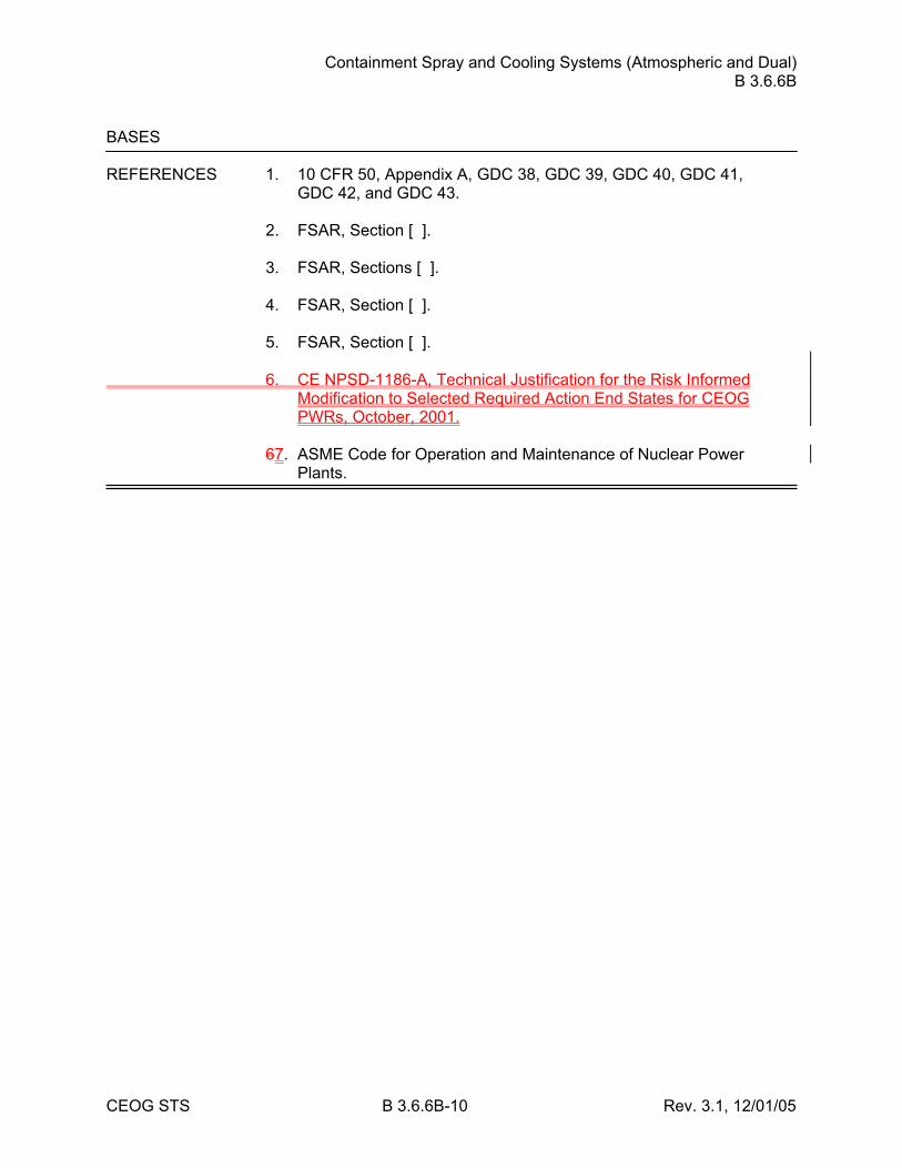
Containment Spray and Cooling Systems (Atmospheric and Dual) B 3.6.6B
CEOG STS B 3.6.6B-10 Rev. 3.1, 12/01/05
BASES REFERENCES 1. 10 CFR 50, Appendix A, GDC 38, GDC 39, GDC 40, GDC 41,
GDC 42, and GDC 43. 2. FSAR, Section [ ]. 3. FSAR, Sections [ ]. 4. FSAR, Section [ ]. 5. FSAR, Section [ ]. 6. CE NPSD-1186-A, Technical Justification for the Risk Informed
Modification to Selected Required Action End States for CEOG PWRs, October, 2001.
67. ASME Code for Operation and Maintenance of Nuclear Power
Plants.
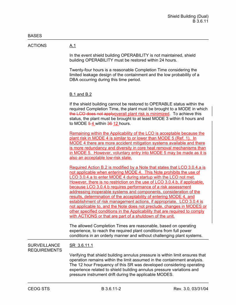
Shield Building (Dual) B 3.6.11
CEOG STS B 3.6.11-2 Rev. 3.0, 03/31/04
BASES ACTIONS A.1
In the event shield building OPERABILITY is not maintained, shield building OPERABILITY must be restored within 24 hours. Twenty-four hours is a reasonable Completion Time considering the limited leakage design of the containment and the low probability of a DBA occurring during this time period. B.1 and B.2 If the shield building cannot be restored to OPERABLE status within the required Completion Time, the plant must be brought to a MODE in which the LCO does not applyoverall plant risk is minimized. To achieve this status, the plant must be brought to at least MODE 3 within 6 hours and to MODE 5 4 within 36 12 hours. Remaining within the Applicability of the LCO is acceptable because the plant risk in MODE 4 is similar to or lower than MODE 5 (Ref. 1). In MODE 4 there are more accident mitigation systems available and there is more redundancy and diversity in core heat removal mechanisms than in MODE 5. However, voluntary entry into MODE 5 may be made as it is also an acceptable low-risk state. Required Action B.2 is modified by a Note that states that LCO 3.0.4.a is not applicable when entering MODE 4. This Note prohibits the use of LCO 3.0.4.a to enter MODE 4 during startup with the LCO not met. However, there is no restriction on the use of LCO 3.0.4.b, if applicable, because LCO 3.0.4.b requires performance of a risk assessment addressing inoperable systems and components, consideration of the results, determination of the acceptability of entering MODE 4, and establishment of risk management actions, if appropriate. LCO 3.0.4 is not applicable to, and the Note does not preclude, changes in MODES or other specified conditions in the Applicability that are required to comply with ACTIONS or that are part of a shutdown of the unit. The allowed Completion Times are reasonable, based on operating experience, to reach the required plant conditions from full power conditions in an orderly manner and without challenging plant systems.
SURVEILLANCE SR 3.6.11.1 REQUIREMENTS
Verifying that shield building annulus pressure is within limit ensures that operation remains within the limit assumed in the containment analysis. The 12 hour Frequency of this SR was developed considering operating experience related to shield building annulus pressure variations and pressure instrument drift during the applicable MODES.
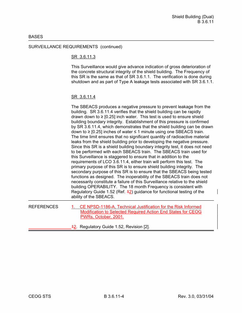
Shield Building (Dual) B 3.6.11
CEOG STS B 3.6.11-4 Rev. 3.0, 03/31/04
BASES SURVEILLANCE REQUIREMENTS (continued)
SR 3.6.11.3 This Surveillance would give advance indication of gross deterioration of the concrete structural integrity of the shield building. The Frequency of this SR is the same as that of SR 3.6.1.1. The verification is done during shutdown and as part of Type A leakage tests associated with SR 3.6.1.1. SR 3.6.11.4 The SBEACS produces a negative pressure to prevent leakage from the building. SR 3.6.11.4 verifies that the shield building can be rapidly drawn down to ≥ [0.25] inch water. This test is used to ensure shield building boundary integrity. Establishment of this pressure is confirmed by SR 3.6.11.4, which demonstrates that the shield building can be drawn down to ≥ [0.25] inches of water ≤ 1 minute using one SBEACS train. The time limit ensures that no significant quantity of radioactive material leaks from the shield building prior to developing the negative pressure. Since this SR is a shield building boundary integrity test, it does not need to be performed with each SBEACS train. The SBEACS train used for this Surveillance is staggered to ensure that in addition to the requirements of LCO 3.6.11.4, either train will perform this test. The primary purpose of this SR is to ensure shield building integrity. The secondary purpose of this SR is to ensure that the SBEACS being tested functions as designed. The inoperability of the SBEACS train does not necessarily constitute a failure of this Surveillance relative to the shield building OPERABILITY. The 18 month Frequency is consistent with Regulatory Guide 1.52 (Ref. 12) guidance for functional testing of the ability of the SBEACS.
REFERENCES 1. CE NPSD-1186-A, Technical Justification for the Risk Informed
Modification to Selected Required Action End States for CEOG PWRs, October, 2001.
12. Regulatory Guide 1.52, Revision [2].
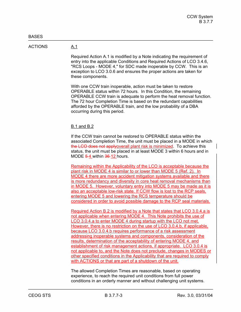
CCW System B 3.7.7
CEOG STS B 3.7.7-3 Rev. 3.0, 03/31/04
BASES ACTIONS A.1
Required Action A.1 is modified by a Note indicating the requirement of entry into the applicable Conditions and Required Actions of LCO 3.4.6, "RCS Loops - MODE 4," for SDC made inoperable by CCW. This is an exception to LCO 3.0.6 and ensures the proper actions are taken for these components. With one CCW train inoperable, action must be taken to restore OPERABLE status within 72 hours. In this Condition, the remaining OPERABLE CCW train is adequate to perform the heat removal function. The 72 hour Completion Time is based on the redundant capabilities afforded by the OPERABLE train, and the low probability of a DBA occurring during this period. B.1 and B.2 If the CCW train cannot be restored to OPERABLE status within the associated Completion Time, the unit must be placed in a MODE in which the LCO does not applyoverall plant risk is minimized. To achieve this status, the unit must be placed in at least MODE 3 within 6 hours and in MODE 5 4 within 36 12 hours. Remaining within the Applicability of the LCO is acceptable because the plant risk in MODE 4 is similar to or lower than MODE 5 (Ref. 2). In MODE 4 there are more accident mitigation systems available and there is more redundancy and diversity in core heat removal mechanisms than in MODE 5. However, voluntary entry into MODE 5 may be made as it is also an acceptable low-risk state. If CCW flow is lost to the RCP seals, entering MODE 5 and lowering the RCS temperature should be considered in order to avoid possible damage to the RCP seal materials. Required Action B.2 is modified by a Note that states that LCO 3.0.4.a is not applicable when entering MODE 4. This Note prohibits the use of LCO 3.0.4.a to enter MODE 4 during startup with the LCO not met. However, there is no restriction on the use of LCO 3.0.4.b, if applicable, because LCO 3.0.4.b requires performance of a risk assessment addressing inoperable systems and components, consideration of the results, determination of the acceptability of entering MODE 4, and establishment of risk management actions, if appropriate. LCO 3.0.4 is not applicable to, and the Note does not preclude, changes in MODES or other specified conditions in the Applicability that are required to comply with ACTIONS or that are part of a shutdown of the unit. The allowed Completion Times are reasonable, based on operating experience, to reach the required unit conditions from full power conditions in an orderly manner and without challenging unit systems.
CCW System B 3.7.7
CEOG STS B 3.7.7-5 Rev. 3.0, 03/31/04
BASES SURVEILLANCE REQUIREMENTS (continued)
SR 3.7.7.2 This SR verifies proper automatic operation of the CCW valves on an actual or simulated actuation signal. The CCW System is a normally operating system that cannot be fully actuated as part of routine testing during normal operation. This Surveillance is not required for valves that are locked, sealed, or otherwise secured in the required position under administrative controls. The [18] month Frequency is based on the need to perform this Surveillance under the conditions that apply during a unit outage and the potential for an unplanned transient if the Surveillance were performed with the reactor at power. Operating experience has shown that these components usually pass the Surveillance when performed at the [18] month Frequency. Therefore, the Frequency is acceptable from a reliability standpoint. SR 3.7.7.3 This SR verifies proper automatic operation of the CCW pumps on an actual or simulated actuation signal. The CCW System is a normally operating system that cannot be fully actuated as part of routine testing during normal operation. The [18] month Frequency is based on the need to perform this Surveillance under the conditions that apply during a unit outage and the potential for an unplanned transient if the Surveillance were performed with the reactor at power. Operating experience has shown these components usually pass the Surveillance when performed at the [18] month Frequency. Therefore, the Frequency is acceptable from a reliability standpoint.
REFERENCES 1. FSAR, Section [9.2.2]. 2. CE NPSD-1186-A, Technical Justification for the Risk Informed
Modification to Selected Required Action End States for CEOG PWRs, October, 2001.
SWS B 3.7.8
CEOG STS B 3.7.8-3 Rev. 3.0, 03/31/04
BASES ACTIONS (continued)
B.1 and B.2 If the SWS train cannot be restored to OPERABLE status within the associated Completion Time, the unit must be placed in a MODE in which the LCO does not applyoverall plant risk is minimized. To achieve this status, the unit must be placed in at least MODE 3 within 6 hours and in MODE 5 4 within 36 12 hours. Remaining within the Applicability of the LCO is acceptable because the plant risk in MODE 4 is similar to or lower than MODE 5 (Ref. 4). In MODE 4 there are more accident mitigation systems available and there is more redundancy and diversity in core heat removal mechanisms than in MODE 5. However, voluntary entry into MODE 5 may be made as it is also an acceptable low-risk state. Required Action B.2 is modified by a Note that states that LCO 3.0.4.a is not applicable when entering MODE 4. This Note prohibits the use of LCO 3.0.4.a to enter MODE 4 during startup with the LCO not met. However, there is no restriction on the use of LCO 3.0.4.b, if applicable, because LCO 3.0.4.b requires performance of a risk assessment addressing inoperable systems and components, consideration of the results, determination of the acceptability of entering MODE 4, and establishment of risk management actions, if appropriate. LCO 3.0.4 is not applicable to, and the Note does not preclude, changes in MODES or other specified conditions in the Applicability that are required to comply with ACTIONS or that are part of a shutdown of the unit. The allowed Completion Times are reasonable, based on operating experience, to reach the required unit conditions from full power conditions in an orderly manner and without challenging unit systems.
SURVEILLANCE SR 3.7.8.1 REQUIREMENTS
Verifying the correct alignment for manual, power operated, and automatic valves in the SWS flow path ensures that the proper flow paths exist for SWS operation. This SR does not apply to valves that are locked, sealed, or otherwise secured in position, since they are verified to be in the correct position prior to locking, sealing, or securing. This SR also does not apply to valves that cannot be inadvertently misaligned, such as check valves. This Surveillance does not require any testing or valve manipulation; rather, it involves verification that those valves capable of potentially being mispositioned are in the correct position. This SR is modified by a Note indicating that the isolation of the SWS components or systems may render those components inoperable but does not affect the OPERABILITY of the SWS.
SWS B 3.7.8
CEOG STS B 3.7.8-5 Rev. 3.0, 03/31/04
BASES SURVEILLANCE REQUIREMENTS (continued)
SR 3.7.8.3 The SR verifies proper automatic operation of the SWS pumps on an actual or simulated actuation signal. The SWS is a normally operating system that cannot be fully actuated as part of the normal testing during normal operation. The [18] month Frequency is based on the need to perform this Surveillance under the conditions that apply during a unit outage and the potential for an unplanned transient if the Surveillance were performed with the reactor at power. Operating experience has shown that these components usually pass the Surveillance when performed at the [18] month Frequency. Therefore, the Frequency is acceptable from a reliability standpoint.
REFERENCES 1. FSAR, Section [9.2.1]. 2. FSAR, Section [6.2]. 3. FSAR, Section [5.4.7]. 4. CE NPSD-1186-A, Technical Justification for the Risk Informed
Modification to Selected Required Action End States for CEOG PWRs, October, 2001.
UHS B 3.7.9
CEOG STS B 3.7.9-3 Rev. 3.0, 03/31/04
BASES ACTIONS [ A.1
If one or more cooling towers have one fan inoperable (i.e., up toat least one fan per cooling tower inoperableis OPERABLE), action must be taken to restored the inoperable cooling tower fan(s) to OPERABLE status within 7 days. The 7 day Completion Time is reasonable, based on the low probability of an accident occurring during the 7 days that one cooling tower fan is inoperable, the number of available systems, and the time required to complete the action. ] B.1 and B.2 If the cooling tower fan cannot be restored to OPERABLE status within the associated Completion Time, the plant must be brought to a MODE in which overall plant risk is minimized. To achieve this status, the plant must be brought to MODE 3 within 6 hours and to MODE 4 within 12 hours. Remaining within the Applicability ofthe LCO is acceptable because the plant risk in MODE 4 is similar to or lower than MODE 5 (Ref. 3). In MODE 4 there are more accident mitigation systems available and there is more redundancy and diversity in core heat removal mechanisms than in MODE 5. However, voluntary entry into MODE 5 may be made as it is also an acceptable low-risk state. Required Action B.2 is modified by a Note that states that LCO 3.0.4.a is not applicable when entering MODE 4. This Note prohibits the use of LCO 3.0.4.a to enter MODE 4 during startup with the LCO not met. However, there is no restriction on the use of LCO 3.0.4.b, if applicable, because LCO 3.0.4.b requires performance of a risk assessment addressing inoperable systems and components, consideration of the results, determination of the acceptability of entering MODE 4, and establishment of risk management actions, if appropriate. LCO 3.0.4 is not applicable to, and the Note does not preclude, changes in MODES or other specified conditions in the Applicability that are required to comply with ACTIONS or that are part of a shutdown of the unit. The allowed Completion Times are reasonable, based on operating experience, to reach the required plant conditions from full power in an orderly manner and without challenging plant systems.
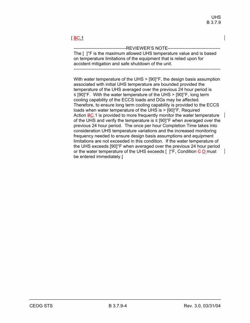
UHS B 3.7.9
CEOG STS B 3.7.9-4 Rev. 3.0, 03/31/04
[ BC.1 -----------------------------------REVIEWER’S NOTE----------------------------------- The [ ]°F is the maximum allowed UHS temperature value and is based on temperature limitations of the equipment that is relied upon for accident mitigation and safe shutdown of the unit. -------------------------------------------------------------------------------------------------- With water temperature of the UHS > [90]°F, the design basis assumption associated with initial UHS temperature are bounded provided the temperature of the UHS averaged over the previous 24 hour period is ≤ [90]°F. With the water temperature of the UHS > [90]°F, long term cooling capability of the ECCS loads and DGs may be affected. Therefore, to ensure long term cooling capability is provided to the ECCS loads when water temperature of the UHS is > [90]°F, Required Action BC.1 is provided to more frequently monitor the water temperature of the UHS and verify the temperature is ≤ [90]°F when averaged over the previous 24 hour period. The once per hour Completion Time takes into consideration UHS temperature variations and the increased monitoring frequency needed to ensure design basis assumptions and equipment limitations are not exceeded in this condition. If the water temperature of the UHS exceeds [90]°F when averaged over the previous 24 hour period or the water temperature of the UHS exceeds [ ]°F, Condition C D must be entered immediately.]
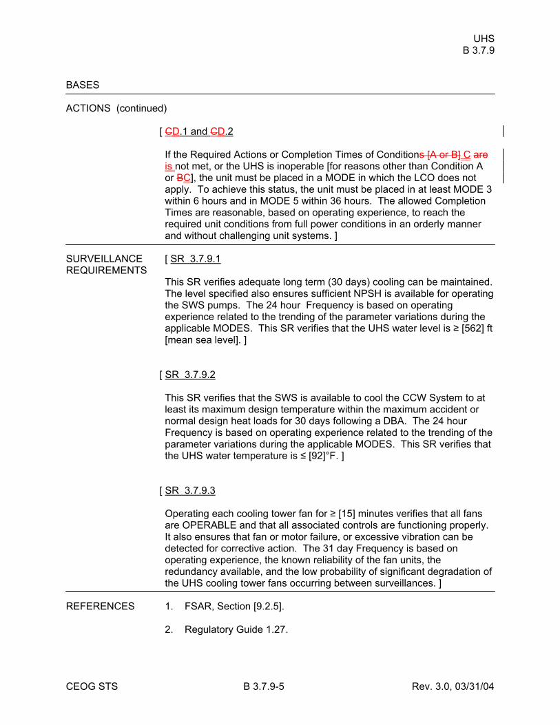
UHS B 3.7.9
CEOG STS B 3.7.9-5 Rev. 3.0, 03/31/04
BASES ACTIONS (continued)
[ CD.1 and CD.2 If the Required Actions or Completion Times of Conditions [A or B] C are is not met, or the UHS is inoperable [for reasons other than Condition A or BC], the unit must be placed in a MODE in which the LCO does not apply. To achieve this status, the unit must be placed in at least MODE 3 within 6 hours and in MODE 5 within 36 hours. The allowed Completion Times are reasonable, based on operating experience, to reach the required unit conditions from full power conditions in an orderly manner and without challenging unit systems. ]
SURVEILLANCE [ SR 3.7.9.1 REQUIREMENTS
This SR verifies adequate long term (30 days) cooling can be maintained. The level specified also ensures sufficient NPSH is available for operating the SWS pumps. The 24 hour Frequency is based on operating experience related to the trending of the parameter variations during the applicable MODES. This SR verifies that the UHS water level is ≥ [562] ft [mean sea level]. ]
[ SR 3.7.9.2 This SR verifies that the SWS is available to cool the CCW System to at least its maximum design temperature within the maximum accident or normal design heat loads for 30 days following a DBA. The 24 hour Frequency is based on operating experience related to the trending of the parameter variations during the applicable MODES. This SR verifies that the UHS water temperature is ≤ [92]°F. ]
[ SR 3.7.9.3 Operating each cooling tower fan for ≥ [15] minutes verifies that all fans are OPERABLE and that all associated controls are functioning properly. It also ensures that fan or motor failure, or excessive vibration can be detected for corrective action. The 31 day Frequency is based on operating experience, the known reliability of the fan units, the redundancy available, and the low probability of significant degradation of the UHS cooling tower fans occurring between surveillances. ]
REFERENCES 1. FSAR, Section [9.2.5]. 2. Regulatory Guide 1.27.
UHS B 3.7.9
CEOG STS B 3.7.9-6 Rev. 3.0, 03/31/04
3. CE NPSD-1186-A, Technical Justification for the Risk Informed Modification to Selected Required Action End States for CEOG PWRs, October, 2001.
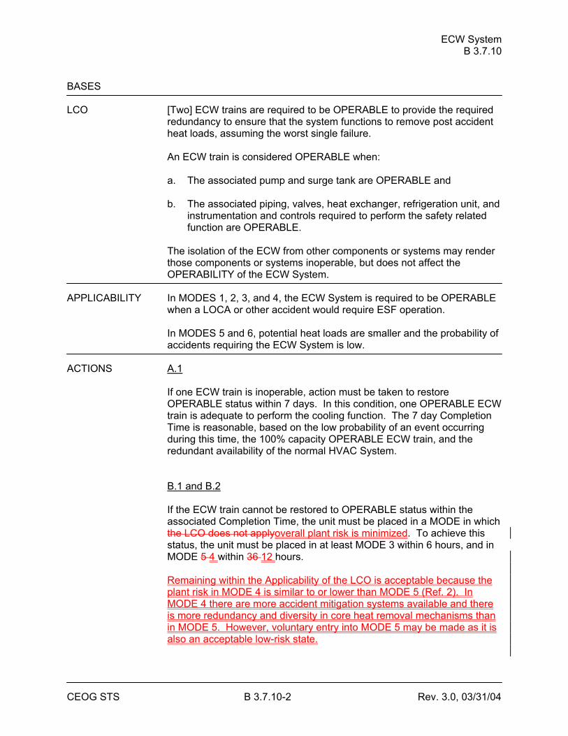
ECW System B 3.7.10
CEOG STS B 3.7.10-2 Rev. 3.0, 03/31/04
BASES LCO [Two] ECW trains are required to be OPERABLE to provide the required
redundancy to ensure that the system functions to remove post accident heat loads, assuming the worst single failure. An ECW train is considered OPERABLE when: a. The associated pump and surge tank are OPERABLE and b. The associated piping, valves, heat exchanger, refrigeration unit, and
instrumentation and controls required to perform the safety related function are OPERABLE.
The isolation of the ECW from other components or systems may render those components or systems inoperable, but does not affect the OPERABILITY of the ECW System.
APPLICABILITY In MODES 1, 2, 3, and 4, the ECW System is required to be OPERABLE
when a LOCA or other accident would require ESF operation. In MODES 5 and 6, potential heat loads are smaller and the probability of accidents requiring the ECW System is low.
ACTIONS A.1
If one ECW train is inoperable, action must be taken to restore OPERABLE status within 7 days. In this condition, one OPERABLE ECW train is adequate to perform the cooling function. The 7 day Completion Time is reasonable, based on the low probability of an event occurring during this time, the 100% capacity OPERABLE ECW train, and the redundant availability of the normal HVAC System. B.1 and B.2 If the ECW train cannot be restored to OPERABLE status within the associated Completion Time, the unit must be placed in a MODE in which the LCO does not applyoverall plant risk is minimized. To achieve this status, the unit must be placed in at least MODE 3 within 6 hours, and in MODE 5 4 within 36 12 hours. Remaining within the Applicability of the LCO is acceptable because the plant risk in MODE 4 is similar to or lower than MODE 5 (Ref. 2). In MODE 4 there are more accident mitigation systems available and there is more redundancy and diversity in core heat removal mechanisms than in MODE 5. However, voluntary entry into MODE 5 may be made as it is also an acceptable low-risk state.
ECW System B 3.7.10
CEOG STS B 3.7.10-3 Rev. 3.0, 03/31/04
Required Action B.2 is modified by a Note that states that LCO 3.0.4.a is not applicable when entering MODE 4. This Note prohibits the use of LCO 3.0.4.a to enter MODE 4 during startup with the LCO not met. However, there is no restriction on the use of LCO 3.0.4.b, if applicable, because LCO 3.0.4.b requires performance of a risk assessment addressing inoperable systems and components, consideration of the results, determination of the acceptability of entering MODE 4, and establishment of risk management actions, if appropriate. LCO 3.0.4 is not applicable to, and the Note does not preclude, changes in MODES or other specified conditions in the Applicability that are required to comply with ACTIONS or that are part of a shutdown of the unit. The allowed Completion Times are reasonable, based on operating experience, to reach the required unit conditions from full power conditions in an orderly manner and without challenging unit systems.
ECW System B 3.7.10
CEOG STS B 3.7.10-4 Rev. 3.0, 03/31/04
BASES SURVEILLANCE SR 3.7.10.1 REQUIREMENTS
Verifying the correct alignment for manual, power operated, and automatic valves in the ECW flow path provides assurance that the proper flow paths exist for ECW operation. This SR does not apply to valves that are locked, sealed, or otherwise secured in position, since they are verified to be in the correct position prior to locking, sealing, or securing. This SR also does not apply to valves that cannot be inadvertently misaligned, such as check valves. This Surveillance does not require any testing or valve manipulation; rather, it involves verification that those valves capable of potentially being mispositioned are in the correct position. This SR is modified by a Note indicating that the isolation of ECW flow to components or systems may render those components inoperable but does not affect the OPERABILITY of the ECW System. The 31 day Frequency is based on engineering judgment, is consistent with the procedural controls governing valve operation, and ensures correct valve positions. SR 3.7.10.2 This SR verifies proper automatic operation of the ECW System components that the ECW pumps will start in the event of any accident or transient that generates an SIAS. This SR also ensures that each automatic valve in the flow paths actuates to its correct position on an actual or simulated SIAS. The ECW System cannot be fully actuated as part of the SIAS CHANNEL FUNCTIONAL TEST during normal operation. The actuation logic is tested as part of the SIAS functional test every 92 days, except for the subgroup relays that actuate the system that cannot be tested during normal unit operation. The [18] month Frequency is based on the need to perform this Surveillance under the conditions that apply during a unit outage and the potential for an unplanned transient if the Surveillance were performed with the reactor at power. The [18] month Frequency is based on operating experience and design reliability of the equipment.
REFERENCES 1. FSAR, Section [9.2.9]. 2. CE NPSD-1186-A, Technical Justification for the Risk Informed
Modification to Selected Required Action End States for CEOG PWRs, October, 2001.
CREACS B 3.7.11
CEOG STS B 3.7.11-4 Rev. 3.0, 03/31/04
BASES ACTIONS A.1
With one CREACS train inoperable, action must be taken to restore OPERABLE status within 7 days. In this Condition, the remaining OPERABLE CREACS subsystem is adequate to perform control room radiation protection function. However, the overall reliability is reduced because a single failure in the OPERABLE CREACS train could result in loss of CREACS function. The 7 day Completion Time is based on the low probability of a DBA occurring during this time period, and the ability of the remaining train to provide the required capability. B.1 -----------------------------------REVIEWER’S NOTE----------------------------------- Adoption of Condition B is dependent on a commitment from the licensee to have written procedures available describing compensatory measures to be taken in the event of an intentional or unintentional entry into Condition B. -------------------------------------------------------------------------------------------------- If the control room boundary is inoperable in MODES 1, 2, 3, and 4, the CREACS trains cannot perform their intended functions. Actions must be taken to restore an OPERABLE control room boundary within 24 hours. During the period that the control room boundary is inoperable, appropriate compensatory measures (consistent with the intent of GDC 19) should be utilized to protect control room operators from potential hazards such as radioactive contamination, toxic chemicals, smoke, temperature and relative humidity, and physical security. Preplanned measures should be available to address these concerns for intentional and unintentional entry into the condition. The 24 hour Completion Time is reasonable based on the low probability of a DBA occurring during this time period, and the use of compensatory measures. The 24 hour Completion Time is a typically reasonable time to diagnose, plan and possibly repair, and test most problems with the control room boundary. C.1 and C.2 If the inoperable CREACS or control room boundary cannot be restored to OPERABLE status within the associated Completion Time in MODE 1, 2, 3, or 4, the unit must be placed in a MODE that minimizes the accidentoverall plant risk. To achieve this status, the unit must be placed in at least MODE 3 within 6 hours, and in MODE 5 4 within 36 12 hours. Remaining within the Applicability of the LCO is acceptable because the plant risk in MODE 4 is similar to or lower than MODE 5 (Ref. 3). In MODE 4 there are more accident mitigation systems available and there
CREACS B 3.7.11
CEOG STS B 3.7.11-5 Rev. 3.0, 03/31/04
is more redundancy and diversity in core heat removal mechanisms than in MODE 5. However, voluntary entry into MODE 5 may be made as it is also an acceptable low-risk state. Required Action C.2 is modified by a Note that states that LCO 3.0.4.a is not applicable when entering MODE 4. This Note prohibits the use of LCO 3.0.4.a to enter MODE 4 during startup with the LCO not met. However, there is no restriction on the use of LCO 3.0.4.b, if applicable, because LCO 3.0.4.b requires performance of a risk assessment addressing inoperable systems and components, consideration of the results, determination of the acceptability of entering MODE 4, and establishment of risk management actions, if appropriate. LCO 3.0.4 is not applicable to, and the Note does not preclude, changes in MODES or other specified conditions in the Applicability that are required to comply with ACTIONS or that are part of a shutdown of the unit. The allowed Completion Times are reasonable, based on operating experience, to reach the required unit conditions from full power conditions in an orderly manner and without challenging unit systems.
CREACS B 3.7.11
CEOG STS B 3.7.11-7 Rev. 3.0, 03/31/04
BASES SURVEILLANCE SR 3.7.11.1 REQUIREMENTS
Standby systems should be checked periodically to ensure that they function properly. Since the environment and normal operating conditions on this system are not severe, testing each train once every month provides an adequate check on this system. Monthly heater operations dry out any moisture accumulated in the charcoal from humidity in the ambient air. [Systems with heaters must be operated for ≥ 10 continuous hours with the heaters energized. Systems without heaters need only be operated for ≥ 15 minutes to demonstrate the function of the system.] The 31 day Frequency is based on the known reliability of the equipment, and the two train redundancy available. SR 3.7.11.2 This SR verifies that the required CREACS testing is performed in accordance with the [Ventilation Filter Testing Program (VFTP)]. The [VFTP] includes testing HEPA filter performance, charcoal adsorber efficiency, minimum system flow rate, and the physical properties of the activated charcoal (general use and following specific operations). Specific test frequencies and additional information are discussed in detail in the [VFTP]. SR 3.7.11.3 This SR verifies each CREACS train starts and operates on an actual or simulated actuation signal. The Frequency of [18] months is consistent with that specified in Reference 34. SR 3.7.11.4 This SR verifies the integrity of the control room enclosure and the assumed inleakage rates of potentially contaminated air. The control room positive pressure, with respect to potentially contaminated adjacent areas, is periodically tested to verify proper function of the CREACS. During the emergency radiation state of the emergency mode of operation, the CREACS is designed to pressurize the control room ≥ [0.125] inches water gauge positive pressure with respect to adjacent areas in order to prevent unfiltered inleakage. The CREACS is designed to maintain this positive pressure with one train at an emergency ventilation flow rate of [3000] cfm. The Frequency of [18] months on a STAGGERED TEST BASIS is consistent with the guidance provided in NUREG-0800, Section 6.4 (Ref. 45).
CREACS B 3.7.11
CEOG STS B 3.7.11-8 Rev. 3.0, 03/31/04
BASES REFERENCES 1. FSAR, Section [9.4]. 2. FSAR, Chapter [15]. 3. CE NPSD-1186-A, Technical Justification for the Risk Informed
Modification to Selected Required Action End States for CEOG PWRs, October, 2001.
34. Regulatory Guide 1.52, Rev. [2]. 45. NUREG-0800, Section 6.4, Rev. 2, July 1981.
CREATCS B 3.7.12
CEOG STS B 3.7.12-2 Rev. 3.0, 03/31/04
BASES APPLICABILITY In MODES 1, 2, 3, 4, [5, and 6,] and during movement of [recently]
irradiated fuel assemblies [(i.e., fuel that has occupied part of a critical reactor core within the previous [X] days)], the CREATCS must be OPERABLE to ensure that the control room temperature will not exceed equipment OPERABILITY requirements following isolation of the control room.
In MODES 5 and 6, CREATCS may not be required for those facilities which do not require automatic control room isolation.
ACTIONS A.1
With one CREATCS train inoperable, action must be taken to restore OPERABLE status within 30 days. In this Condition, the remaining OPERABLE CREATCS train is adequate to maintain the control room temperature within limits. The 30 day Completion Time is reasonable, based on the low probability of an event occurring requiring control room isolation, consideration that the remaining train can provide the required capabilities, and the alternate safety or nonsafety related cooling means that are available. B.1 and B.2 In MODE 1, 2, 3, or 4, when Required Action A.1 cannot be completed within the required Completion Time, the unit must be placed in a MODE that minimizes the accidentoverall plant risk risk. To achieve this status, the unit must be placed in at least MODE 3 within 6 hours, and in MODE 5 4 within 36 12 hours. Remaining within the Applicability of the LCO is acceptable because the plant risk in MODE 4 is similar to or lower than MODE 5 (Ref. 2). In MODE 4 there are more accident mitigation systems available and there is more redundancy and diversity in core heat removal mechanisms than in MODE 5. However, voluntary entry into MODE 5 may be made as it is also an acceptable low-risk state. Required Action B.2 is modified by a Note that states that LCO 3.0.4.a is not applicable when entering MODE 4. This Note prohibits the use of LCO 3.0.4.a to enter MODE 4 during startup with the LCO not met. However, there is no restriction on the use of LCO 3.0.4.b, if applicable, because LCO 3.0.4.b requires performance of a risk assessment addressing inoperable systems and components, consideration of the results, determination of the acceptability of entering MODE 4, and establishment of risk management actions, if appropriate. LCO 3.0.4 is not applicable to, and the Note does not preclude, changes in MODES or other specified conditions in the Applicability that are required to comply with ACTIONS or that are part of a shutdown of the unit.
CREATCS B 3.7.12
CEOG STS B 3.7.12-3 Rev. 3.0, 03/31/04
The allowed Completion Times are reasonable, based on operating experience, to reach the required unit conditions from full power conditions in an orderly manner and without challenging unit systems.
[ C.1 and C.2 In MODE 5 or 6, or during movement of [recently] irradiated fuel assemblies, when Required Action A.1 cannot be completed within the required Completion Time, the OPERABLE CREATCS train must be placed in operation immediately. This action ensures that the remaining train is OPERABLE, that no failures preventing automatic actuation will occur, and that any active failure will be readily detected. An alternative to Required Action C.1 is to immediately suspend activities that could result in a release of radioactivity that might require isolation of the control room. This places the unit in a condition that minimizes the accident risk. This does not preclude the movement of fuel assemblies to a safe position. ]
CREATCS B 3.7.12
CEOG STS B 3.7.12-4 Rev. 3.0, 03/31/04
BASES ACTIONS (continued)
[ D.1 In [MODE 5 or 6, or] during movement of [recently] irradiated fuel assemblies, with two CREATCS trains inoperable, action must be taken immediately to suspend activities that could result in a release of radioactivity that might require isolation of the control room. This places the unit in a condition that minimizes the accident risk. This does not preclude the movement of fuel to a safe position. ] E.1 If both CREATCS trains are inoperable in MODE 1, 2, 3, or 4, the CREATCS may not be capable of performing the intended function and the unit is in a condition outside the accident analysis. Therefore, LCO 3.0.3 must be entered immediately.
SURVEILLANCE SR 3.7.12.1 REQUIREMENTS
This SR verifies that the heat removal capability of the system is sufficient to meet design requirements. This SR consists of a combination of testing and calculations. An [18] month Frequency is appropriate, since significant degradation of the CREATCS is slow and is not expected over this time period.
REFERENCES 1. FSAR, Section [6.4]. 2. CE NPSD-1186-A, Technical Justification for the Risk Informed
Modification to Selected Required Action End States for CEOG PWRs, October, 2001.
ECCS PREACS B 3.7.13
CEOG STS B 3.7.13-4 Rev. 3.0, 03/31/04
BASES ACTIONS (continued)
If the ECCS pump room boundary is inoperable, the ECCS PREACS trains cannot perform their intended functions. Actions must be taken to restore an OPERABLE ECCS pump room boundary within 24 hours. During the period that the ECCS pump room boundary is inoperable, appropriate compensatory measures [consistent with the intent, as applicable, of GDC 19, 60, 64 and 10 CFR Part 100] should be utilized to protect plant personnel from potential hazards such as radioactive contamination, toxic chemicals, smoke, temperature and relative humidity, and physical security. Preplanned measures should be available to address these concerns for intentional and unintentional entry into the condition. The 24 hour Completion Time is reasonable based on the low probability of a DBA occurring during this time period, and the use of compensatory measures. The 24 hour Completion Time is a typically reasonable time to diagnose, plan and possibly repair, and test most problems with the ECCS pump room boundary. C.1 and C.2 If the ECCS PREACS train or ECCS pump room boundary cannot be restored to OPERABLE status within the associated Completion Time, the unit must be in a MODE in which the LCO does not applyoverall plant risk is minimized. To achieve this status, the unit must be placed in at least MODE 3 within 6 hours, and in MODE 5 4 within 36 12 hours. Remaining within the Applicability of the LCO is acceptable because the plant risk in MODE 4 is similar to or lower than MODE 5 (Ref. 6). In MODE 4 there are more accident mitigation systems available and there is more redundancy and diversity in core heat removal mechanisms than in MODE 5. However, voluntary entry into MODE 5 may be made as it is also an acceptable low-risk state. Required Action C.2 is modified by a Note that states that LCO 3.0.4.a is not applicable when entering MODE 4. This Note prohibits the use of LCO 3.0.4.a to enter MODE 4 during startup with the LCO not met. However, there is no restriction on the use of LCO 3.0.4.b, if applicable, because LCO 3.0.4.b requires performance of a risk assessment addressing inoperable systems and components, consideration of the results, determination of the acceptability of entering MODE 4, and establishment of risk management actions, if appropriate. LCO 3.0.4 is not applicable to, and the Note does not preclude, changes in MODES or other specified conditions in the Applicability that are required to comply with ACTIONS or that are part of a shutdown of the unit.
ECCS PREACS B 3.7.13
CEOG STS B 3.7.13-5 Rev. 3.0, 03/31/04
The allowed Completion Times are reasonable, based on operating experience, to reach the required unit conditions from full power conditions in an orderly manner and without challenging unit systems.
SURVEILLANCE SR 3.7.13.1 REQUIREMENTS
Standby systems should be checked periodically to ensure that they function properly. Since the environment and normal operating conditions on this system are not severe, testing each train once a month provides an adequate check on this system. Monthly heater operations dry out any moisture that may have accumulated in the charcoal from humidity in the ambient air. [Systems with heaters must be operated for ≥ 10 continuous hours with the heaters energized. Systems without heaters need only be operated for ≥ 15 minutes to demonstrate the function of the system.] The 31 day Frequency is based on the known reliability of equipment, and the two train redundancy available.
ECCS PREACS B 3.7.13
CEOG STS B 3.7.13-6 Rev. 3.0, 03/31/04
BASES SURVEILLANCE REQUIREMENTS (continued)
SR 3.7.13.2 This SR verifies that the required ECCS PREACS testing is performed in accordance with the [Ventilation Filter Testing Program (VFTP)]. The [VFTP] includes testing HEPA filter performance, charcoal adsorber efficiency, minimum system flow rate, and the physical properties of the activated charcoal (general use and following specific operations). Specific test frequencies and additional information are discussed in detail in the [VFTP]. SR 3.7.13.3 This SR verifies that each ECCS PREACS train starts and operates on an actual or simulated actuation signal. The [18] month Frequency is consistent with that specified in Regulatory Guide 1.52 (Ref. 4). SR 3.7.13.4 This SR verifies the integrity of the ECCS pump room enclosure. The ability of the ECCS pump room to maintain a negative pressure, with respect to potentially uncontaminated adjacent areas, is periodically tested to verify proper function of the ECCS PREACS. During the post accident mode of operation, the ECCS PREACS is designed to maintain a slight negative pressure in the ECCS pump room with respect to adjacent areas to prevent unfiltered LEAKAGE. The ECCS PREACS is designed to maintain this negative pressure at a flow rate of ≤ [20,000] cfm from the ECCS pump room. The Frequency of [18] months is consistent with the guidance provided in the NUREG-0800, Section 6.5.1 (Ref. 67). This test is conducted with the tests for filter penetration; thus, an [18] month Frequency, on a STAGGERED TEST BASIS is consistent with other filtration SRs.
[ SR 3.7.13.5 Operating the ECCS PREACS filter bypass damper is necessary to ensure that the system functions properly. The OPERABILITY of the bypass damper is verified if it can be closed. An [18] month Frequency is consistent with that specified in Reference 4. ]
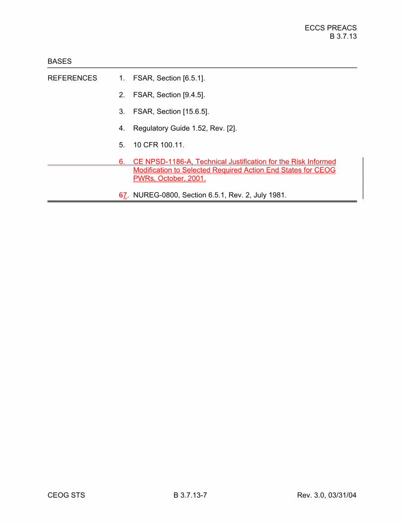
ECCS PREACS B 3.7.13
CEOG STS B 3.7.13-7 Rev. 3.0, 03/31/04
BASES REFERENCES 1. FSAR, Section [6.5.1]. 2. FSAR, Section [9.4.5]. 3. FSAR, Section [15.6.5]. 4. Regulatory Guide 1.52, Rev. [2]. 5. 10 CFR 100.11. 6. CE NPSD-1186-A, Technical Justification for the Risk Informed
Modification to Selected Required Action End States for CEOG PWRs, October, 2001.
67. NUREG-0800, Section 6.5.1, Rev. 2, July 1981.
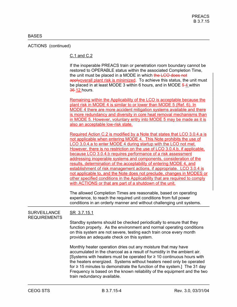
PREACS B 3.7.15
CEOG STS B 3.7.15-4 Rev. 3.0, 03/31/04
BASES ACTIONS (continued)
C.1 and C.2 If the inoperable PREACS train or penetration room boundary cannot be restored to OPERABLE status within the associated Completion Time, the unit must be placed in a MODE in which the LCO does not applyoverall plant risk is minimized. To achieve this status, the unit must be placed in at least MODE 3 within 6 hours, and in MODE 5 4 within 36 12 hours. Remaining within the Applicability of the LCO is acceptable because the plant risk in MODE 4 is similar to or lower than MODE 5 (Ref. 6). In MODE 4 there are more accident mitigation systems available and there is more redundancy and diversity in core heat removal mechanisms than in MODE 5. However, voluntary entry into MODE 5 may be made as it is also an acceptable low-risk state. Required Action C.2 is modified by a Note that states that LCO 3.0.4.a is not applicable when entering MODE 4. This Note prohibits the use of LCO 3.0.4.a to enter MODE 4 during startup with the LCO not met. However, there is no restriction on the use of LCO 3.0.4.b, if applicable, because LCO 3.0.4.b requires performance of a risk assessment addressing inoperable systems and components, consideration of the results, determination of the acceptability of entering MODE 4, and establishment of risk management actions, if appropriate. LCO 3.0.4 is not applicable to, and the Note does not preclude, changes in MODES or other specified conditions in the Applicability that are required to comply with ACTIONS or that are part of a shutdown of the unit. The allowed Completion Times are reasonable, based on operating experience, to reach the required unit conditions from full power conditions in an orderly manner and without challenging unit systems.
SURVEILLANCE SR 3.7.15.1 REQUIREMENTS
Standby systems should be checked periodically to ensure that they function properly. As the environment and normal operating conditions on this system are not severe, testing each train once every month provides an adequate check on this system. Monthly heater operation dries out any moisture that may have accumulated in the charcoal as a result of humidity in the ambient air. [Systems with heaters must be operated for ≥ 10 continuous hours with the heaters energized. Systems without heaters need only be operated for ≥ 15 minutes to demonstrate the function of the system.] The 31 day Frequency is based on the known reliability of the equipment and the two train redundancy available.
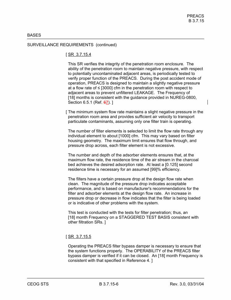
PREACS B 3.7.15
CEOG STS B 3.7.15-6 Rev. 3.0, 03/31/04
BASES SURVEILLANCE REQUIREMENTS (continued)
[ SR 3.7.15.4 This SR verifies the integrity of the penetration room enclosure. The ability of the penetration room to maintain negative pressure, with respect to potentially uncontaminated adjacent areas, is periodically tested to verify proper function of the PREACS. During the post accident mode of operation, PREACS is designed to maintain a slightly negative pressure at a flow rate of ≤ [3000] cfm in the penetration room with respect to adjacent areas to prevent unfiltered LEAKAGE. The Frequency of [18] months is consistent with the guidance provided in NUREG-0800, Section 6.5.1 (Ref. 67). ]
[ The minimum system flow rate maintains a slight negative pressure in the penetration room area and provides sufficient air velocity to transport particulate contaminants, assuming only one filter train is operating. The number of filter elements is selected to limit the flow rate through any individual element to about [1000] cfm. This may vary based on filter housing geometry. The maximum limit ensures that flow through, and pressure drop across, each filter element is not excessive. The number and depth of the adsorber elements ensures that, at the maximum flow rate, the residence time of the air stream in the charcoal bed achieves the desired adsorption rate. At least a [0.125] second residence time is necessary for an assumed [99]% efficiency. The filters have a certain pressure drop at the design flow rate when clean. The magnitude of the pressure drop indicates acceptable performance, and is based on manufacturer's recommendations for the filter and adsorber elements at the design flow rate. An increase in pressure drop or decrease in flow indicates that the filter is being loaded or is indicative of other problems with the system. This test is conducted with the tests for filter penetration; thus, an [18] month Frequency on a STAGGERED TEST BASIS consistent with other filtration SRs. ]
[ SR 3.7.15.5 Operating the PREACS filter bypass damper is necessary to ensure that the system functions properly. The OPERABILITY of the PREACS filter bypass damper is verified if it can be closed. An [18] month Frequency is consistent with that specified in Reference 4. ]
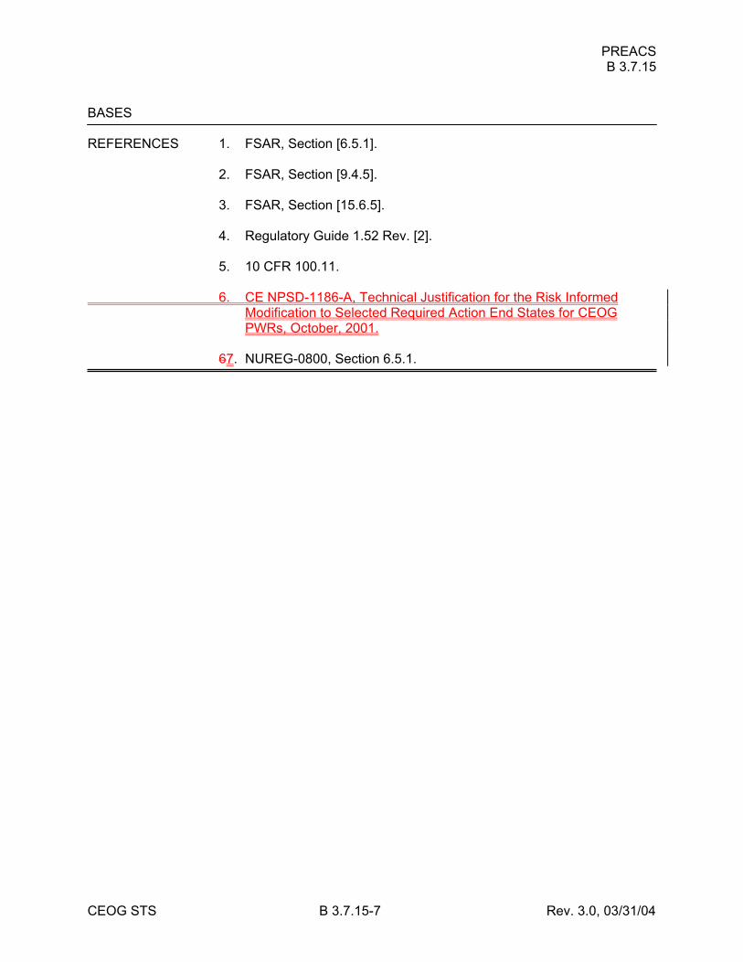
PREACS B 3.7.15
CEOG STS B 3.7.15-7 Rev. 3.0, 03/31/04
BASES REFERENCES 1. FSAR, Section [6.5.1]. 2. FSAR, Section [9.4.5]. 3. FSAR, Section [15.6.5]. 4. Regulatory Guide 1.52 Rev. [2]. 5. 10 CFR 100.11. 6. CE NPSD-1186-A, Technical Justification for the Risk Informed
Modification to Selected Required Action End States for CEOG PWRs, October, 2001.
67. NUREG-0800, Section 6.5.1.
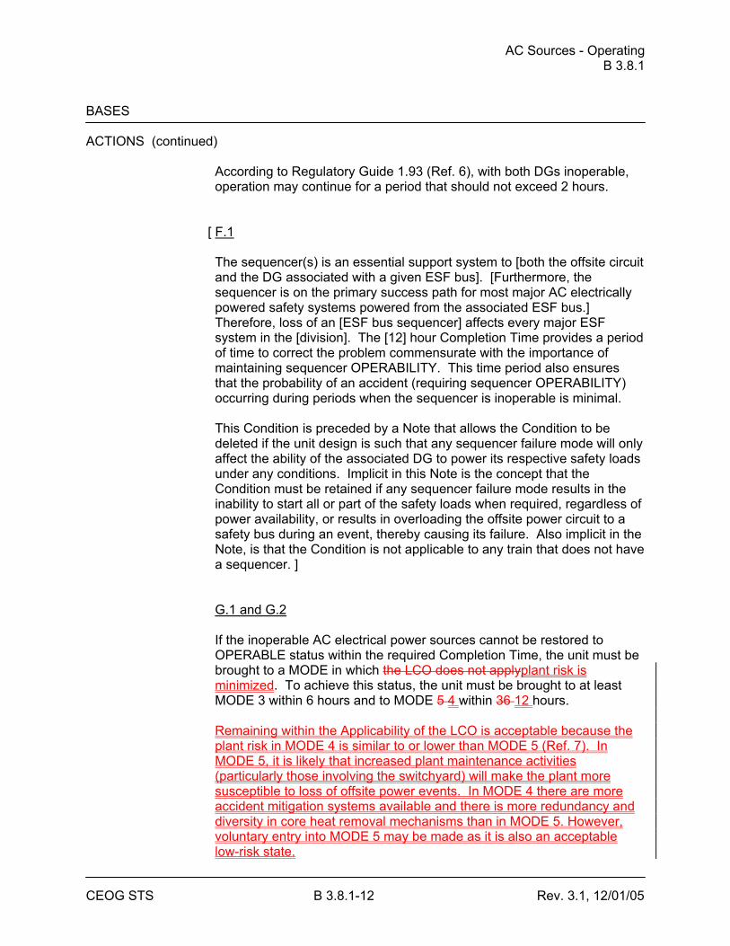
AC Sources - Operating B 3.8.1
CEOG STS B 3.8.1-12 Rev. 3.1, 12/01/05
BASES ACTIONS (continued)
According to Regulatory Guide 1.93 (Ref. 6), with both DGs inoperable, operation may continue for a period that should not exceed 2 hours.
[ F.1 The sequencer(s) is an essential support system to [both the offsite circuit and the DG associated with a given ESF bus]. [Furthermore, the sequencer is on the primary success path for most major AC electrically powered safety systems powered from the associated ESF bus.] Therefore, loss of an [ESF bus sequencer] affects every major ESF system in the [division]. The [12] hour Completion Time provides a period of time to correct the problem commensurate with the importance of maintaining sequencer OPERABILITY. This time period also ensures that the probability of an accident (requiring sequencer OPERABILITY) occurring during periods when the sequencer is inoperable is minimal. This Condition is preceded by a Note that allows the Condition to be deleted if the unit design is such that any sequencer failure mode will only affect the ability of the associated DG to power its respective safety loads under any conditions. Implicit in this Note is the concept that the Condition must be retained if any sequencer failure mode results in the inability to start all or part of the safety loads when required, regardless of power availability, or results in overloading the offsite power circuit to a safety bus during an event, thereby causing its failure. Also implicit in the Note, is that the Condition is not applicable to any train that does not have a sequencer. ] G.1 and G.2 If the inoperable AC electrical power sources cannot be restored to OPERABLE status within the required Completion Time, the unit must be brought to a MODE in which the LCO does not applyplant risk is minimized. To achieve this status, the unit must be brought to at least MODE 3 within 6 hours and to MODE 5 4 within 36 12 hours. Remaining within the Applicability of the LCO is acceptable because the plant risk in MODE 4 is similar to or lower than MODE 5 (Ref. 7). In MODE 5, it is likely that increased plant maintenance activities (particularly those involving the switchyard) will make the plant more susceptible to loss of offsite power events. In MODE 4 there are more accident mitigation systems available and there is more redundancy and diversity in core heat removal mechanisms than in MODE 5. However, voluntary entry into MODE 5 may be made as it is also an acceptable low-risk state.
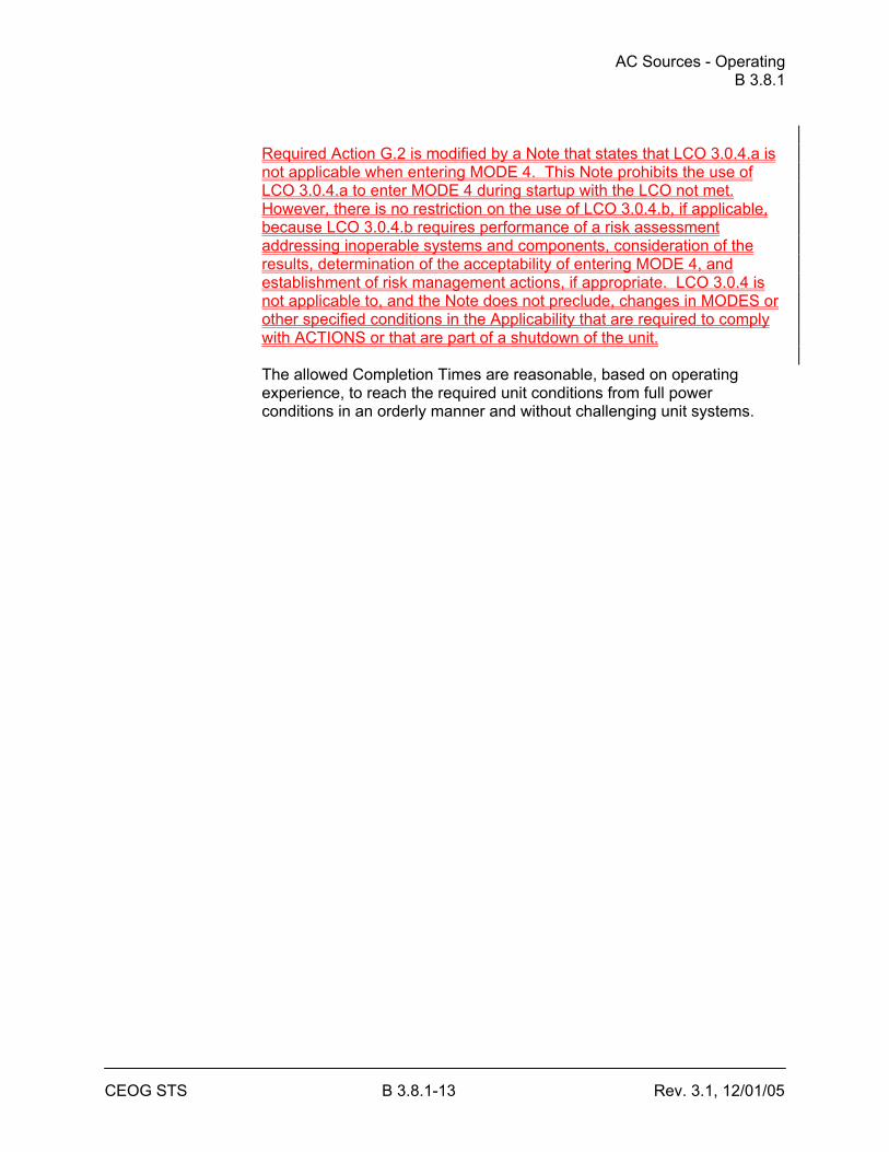
AC Sources - Operating B 3.8.1
CEOG STS B 3.8.1-13 Rev. 3.1, 12/01/05
Required Action G.2 is modified by a Note that states that LCO 3.0.4.a is not applicable when entering MODE 4. This Note prohibits the use of LCO 3.0.4.a to enter MODE 4 during startup with the LCO not met. However, there is no restriction on the use of LCO 3.0.4.b, if applicable, because LCO 3.0.4.b requires performance of a risk assessment addressing inoperable systems and components, consideration of the results, determination of the acceptability of entering MODE 4, and establishment of risk management actions, if appropriate. LCO 3.0.4 is not applicable to, and the Note does not preclude, changes in MODES or other specified conditions in the Applicability that are required to comply with ACTIONS or that are part of a shutdown of the unit. The allowed Completion Times are reasonable, based on operating experience, to reach the required unit conditions from full power conditions in an orderly manner and without challenging unit systems.
AC Sources - Operating B 3.8.1
CEOG STS B 3.8.1-14 Rev. 3.1, 12/01/05
BASES ACTIONS (continued)
H.1
Condition H corresponds to a level of degradation in which all redundancy in the AC electrical power supplies has been lost. At this severely degraded level, any further losses in the AC electrical power system will cause a loss of function. Therefore, no additional time is justified for continued operation. The unit is required by LCO 3.0.3 to commence a controlled shutdown.
SURVEILLANCE The AC sources are designed to permit inspection and testing of all REQUIREMENTS important areas and features, especially those that have a standby
function, in accordance with 10 CFR 50, Appendix A, GDC 18 (Ref. 89). Periodic component tests are supplemented by extensive functional tests during refueling outages (under simulated accident conditions). The SRs for demonstrating the OPERABILITY of the DGs are in accordance with the recommendations of Regulatory Guide 1.9 (Ref. 3), Regulatory Guide 1.108 (Ref. 910), and Regulatory Guide 1.137 (Ref. 1011), as addressed in the FSAR.
Where the SRs discussed herein specify voltage and frequency tolerances, the following is applicable. The minimum steady state output voltage of [3740] V is 90% of the nominal 4160 V output voltage. This value, which is specified in ANSI C84.1-1982 (Ref. 1112), allows for voltage drop to the terminals of 4000 V motors whose minimum operating voltage is specified as 90% or 3600 V. It also allows for voltage drops to motors and other equipment down through the 120 V level where minimum operating voltage is also usually specified as 80% of name plate rating. The specified maximum steady state output voltage of [4756] V is equal to the maximum operating voltage specified for 4000 V motors. It ensures that for a lightly loaded distribution system, the voltage at the terminals of 4000 V motors is no more than the maximum rated operating voltages. The specified minimum and maximum frequencies of the DG are 58.8 Hz and 61.2 Hz, respectively. These values are equal to ± 2% of the 60 Hz nominal frequency and are derived from the recommendations given in Regulatory Guide 1.9 (Ref. 3).
AC Sources - Operating B 3.8.1
CEOG STS B 3.8.1-15 Rev. 3.1, 12/01/05
BASES SURVEILLANCE REQUIREMENTS (continued)
SR 3.8.1.1 This SR assures proper circuit continuity for the offsite AC electrical power supply to the onsite distribution network and availability of offsite AC electrical power. The breaker alignment verifies that each breaker is in its correct position to ensure that distribution buses and loads are connected to their preferred power source, and that appropriate independence of offsite circuits is maintained. The 7 day Frequency is adequate since breaker position is not likely to change without the operator being aware of it and because its status is displayed in the control room. SR 3.8.1.2 and SR 3.8.1.7 These SRs help to ensure the availability of the standby electrical power supply to mitigate DBAs and transients and to maintain the unit in a safe shutdown condition. To minimize the wear on moving parts that do not get lubricated when the engine is not running, these SRs are modified by a Note (Note 1 for SR 3.8.1.2 and Note for SR 3.8.1.7) to indicate that all DG starts for these Surveillances may be preceded by an engine prelube period and followed by a warmup period prior to loading by an engine prelube period. For the purposes of SR 3.8.1.2 and SR 3.8.1.7 testing, the DGs are started from standby conditions. Standby conditions for a DG mean the diesel engine coolant and oil are being continuously circulated and temperature is being maintained consistent with manufacturer recommendations.
[ In order to reduce stress and wear on diesel engines, the DG manufacturers recommend a modified start in which the starting speed of DGs is limited, warmup is limited to this lower speed, and the DGs are gradually accelerated to synchronous speed prior to loading. This is the intent of Note 2, which is only applicable when such modified start procedures are recommended by the manufacturer. SR 3.8.1.7 requires that, at a 184 day Frequency, the DG starts from standby conditions and achieves required voltage and frequency within 10 seconds. The 10 second start requirement supports the assumptions of the design basis LOCA analysis in the FSAR, Chapter [15] (Ref. 5). ]
AC Sources - Operating B 3.8.1
CEOG STS B 3.8.1-16 Rev. 3.1, 12/01/05
BASES SURVEILLANCE REQUIREMENTS (continued)
The 10 second start requirement is not applicable to SR 3.8.1.2 (see Note 2) when a modified start procedure as described above is used. If a modified start is not used, 10 second start requirement of SR 3.8.1.7 applies. Since SR 3.8.1.7 requires a 10 second start, it is more restrictive than SR 3.8.1.2, and it may be performed in lieu of SR 3.8.1.2. In addition to the SR requirements, the time for the DG to reach steady state operation, unless the modified DG start method is employed, is periodically monitored and the trend evaluated to identify degradation of governor and voltage regulator performance.
The 31 day Frequency for SR 3.8.1.2 is consistent with Regulatory Guide 1.9 (Ref. 3). The 184 day Frequency for SR 3.8.1.7 is a reduction in cold testing consistent with Generic Letter 84-15 (Ref. 78). These Frequencies provide adequate assurance of DG OPERABILITY, while minimizing degradation resulting from testing. SR 3.8.1.3 This Surveillance verifies that the DGs are capable of synchronizing with the offsite electrical system and accepting loads greater than or equal to the equivalent of the maximum expected accident loads. A minimum run time of 60 minutes is required to stabilize engine temperatures, while minimizing the time that the DG is connected to the offsite source. Although no power factor requirements are established by this SR, the DG is normally operated at a power factor between [0.8 lagging] and [1.0]. The 0.8 value is the design rating of the machine, while [1.0] is an operational limitation [to ensure circulating currents are minimized]. The 31 day Frequency for this Surveillance is consistent with Regulatory Guide 1.9 (Ref. 3). This SR is modified by four Notes. Note 1 indicates that diesel engine runs for this Surveillance may include gradual loading, as recommended by the manufacturer, so that mechanical stress and wear on the diesel engine are minimized. Note 2 states that momentary transients because of changing bus loads do not invalidate this test. Similarly, momentary power factor transients above the limit will not invalidate the test. Note 3 indicates that this Surveillance should be conducted on only one DG at a time in order to avoid common cause failures that might result from offsite circuit or grid perturbations. Note 4 stipulates a prerequisite requirement for performance of this SR. A successful DG start must precede this test to credit satisfactory performance.
AC Sources - Operating B 3.8.1
CEOG STS B 3.8.1-17 Rev. 3.1, 12/01/05
BASES SURVEILLANCE REQUIREMENTS (continued)
SR 3.8.1.4 This SR provides verification that the level of fuel oil in the day tank [and engine mounted tank] is at or above the level at which fuel oil is automatically added. The level is expressed as an equivalent volume in gallons, and is selected to ensure adequate fuel oil for a minimum of 1 hour of DG operation at full load plus 10%. The 31 day Frequency is adequate to assure that a sufficient supply of fuel oil is available, since low level alarms are provided and unit operators would be aware of any large uses of fuel oil during this period. SR 3.8.1.5 Microbiological fouling is a major cause of fuel oil degradation. There are numerous bacteria that can grow in fuel oil and cause fouling, but all must have a water environment in order to survive. Removal of water from the fuel oil day [and engine mounted] tanks once every [31] days eliminates the necessary environment for bacterial survival. This is the most effective means of controlling microbiological fouling. In addition, it eliminates the potential for water entrainment in the fuel oil during DG operation. Water may come from any of several sources, including condensation, ground water, rain water, contaminated fuel oil, and from breakdown of the fuel oil by bacteria. Frequent checking for and removal of accumulated water minimizes fouling and provides data regarding the watertight integrity of the fuel oil system. The Surveillance Frequencies are established by Regulatory Guide 1.137 (Ref. 1011). This SR is for preventive maintenance. The presence of water does not necessarily represent failure of this SR provided the accumulated water is removed during the performance of this Surveillance. SR 3.8.1.6 This Surveillance demonstrates that each required fuel oil transfer pump operates and transfers fuel oil from its associated storage tank to its associated day tank. This is required to support continuous operation of standby power sources. This Surveillance provides assurance that the fuel oil transfer pump is OPERABLE, the fuel oil piping system is intact, the fuel delivery piping is not obstructed, and the controls and control systems for automatic fuel transfer systems are OPERABLE.
AC Sources - Operating B 3.8.1
CEOG STS B 3.8.1-18 Rev. 3.1, 12/01/05
BASES SURVEILLANCE REQUIREMENTS (continued)
[ The Frequency for this SR is variable, depending on individual system design, with up to a [92] day interval. The [92] day Frequency corresponds to the testing requirements for pumps as contained in the ASME Code (Ref. 1213); however, the design of fuel transfer systems is such that pumps will operate automatically or must be started manually in order to maintain an adequate volume of fuel oil in the day [and engine mounted] tanks during or following DG testing. In such a case, a 31 day Frequency is appropriate. Since proper operation of fuel transfer systems is an inherent part of DG OPERABILITY, the Frequency of this SR should be modified to reflect individual designs. ] SR 3.8.1.7 See SR 3.8.1.2.
[ SR 3.8.1.8 Transfer of each [4.16 kV ESF bus] power supply from the normal offsite circuit to the alternate offsite circuit demonstrates the OPERABILITY of the alternate circuit distribution network to power the shutdown loads. The [18 month] Frequency of the Surveillance is based on engineering judgment, taking into consideration the unit conditions required to perform the Surveillance, and is intended to be consistent with expected fuel cycle lengths. Operating experience has shown that these components usually pass the SR when performed at the [18 month] Frequency. Therefore, the Frequency was concluded to be acceptable from a reliability standpoint. This SR is modified by a Note. The reason for the Note is that during operation with the reactor critical, performance of this SR could cause perturbations to the electrical distribution systems that could challenge continued steady state operation and, as a result, unit safety systems. This restriction from normally performing the Surveillance in MODE 1 or 2 is further amplified to allow the Surveillance to be performed for the purpose of reestablishing OPERABILITY (e.g., post work testing following corrective maintenance, corrective modification, deficient or incomplete surveillance testing, and other unanticipated OPERABILITY concerns) provided an assessment determines plant safety is maintained or enhanced. This assessment shall, as a minimum, consider the potential outcomes and transients associated with a failed Surveillance, a successful Surveillance, and a perturbation of the offsite or onsite system
AC Sources - Operating B 3.8.1
CEOG STS B 3.8.1-19 Rev. 3.1, 12/01/05
BASES SURVEILLANCE REQUIREMENTS (continued)
when they are tied together or operated independently for the Surveillance; as well as the operator procedures available to cope with these outcomes. These shall be measured against the avoided risk of a plant shutdown and startup to determine that plant safety is maintained or enhanced when the Surveillance is performed in MODE 1 or 2. Risk insights or deterministic methods may be used for this assessment. Credit may be taken for unplanned events that satisfy this SR .] SR 3.8.1.9 Each DG is provided with an engine overspeed trip to prevent damage to the engine. Recovery from the transient caused by the loss of a large load could cause diesel engine overspeed, which, if excessive, might result in a trip of the engine. This Surveillance demonstrates the DG load response characteristics and capability to reject the largest single load without exceeding predetermined voltage and frequency and while maintaining a specified margin to the overspeed trip. [For this unit, the single load for each DG and its horsepower rating is as follows:] This Surveillance may be accomplished by: a. Tripping the DG output breaker with the DG carrying greater than or
equal to its associated single largest post-accident load while paralleled to offsite power or while solely supplying the bus, or
b. Tripping its associated single largest post-accident load with the DG
solely supplying the bus. As required by IEEE-308 (Ref. 1314), the load rejection test is acceptable if the increase in diesel speed does not exceed 75% of the difference between synchronous speed and the overspeed trip setpoint, or 15% above synchronous speed, whichever is lower. The time, voltage, and frequency tolerances specified in this SR are derived from Regulatory Guide 1.9 (Ref. 3) recommendations for response during load sequence intervals. The [3] seconds specified is equal to 60% of a typical 5 second load sequence interval associated with sequencing of the largest load. The voltage and frequency specified are consistent with the design range of the equipment powered by the DG. SR 3.8.1.9.a corresponds to the maximum frequency excursion, while SR 3.8.1.9.b and SR 3.8.1.9.c are steady state voltage and frequency values to which the system must recover following load rejection. The [18 month] Frequency is consistent with the recommendation of Regulatory Guide 1.108 (Ref. 910).
AC Sources - Operating B 3.8.1
CEOG STS B 3.8.1-21 Rev. 3.1, 12/01/05
BASES SURVEILLANCE REQUIREMENTS (continued)
b. Performance of the SR will not cause perturbations to any of the
electrical distribution systems that could result in a challenge to steady state operation or to plant safety systems, and
c. Performance of the SR or failure of the SR will not cause or result in
an AOO with attendant challenge to plant safety systems. --------------------------------------------------------------------------------------------------
SR 3.8.1.10 This Surveillance demonstrates the DG capability to reject a full load without overspeed tripping or exceeding the predetermined voltage limits. The DG full load rejection may occur because of a system fault or inadvertent breaker tripping. This Surveillance ensures proper engine generator load response under the simulated test conditions. This test simulates the loss of the total connected load that the DG experiences following a full load rejection and verifies that the DG will not trip upon loss of the load. These acceptance criteria provide DG damage protection. While the DG is not expected to experience this transient during an event and continues to be available, this response ensures that the DG is not degraded for future application, including reconnection to the bus if the trip initiator can be corrected or isolated. The [18 month] Frequency is consistent with the recommendation of Regulatory Guide 1.108 (Ref. 910) and is intended to be consistent with expected fuel cycle lengths. This SR is modified by two Notes. The reason for Note 1 is that during operation with the reactor critical, performance of this SR could cause perturbation to the electrical distribution systems that could challenge continued steady state operation and, as a result, unit safety systems. This restriction from normally performing the Surveillance in MODE 1 or 2 is further amplified to allow the Surveillance to be performed for the purpose of reestablishing OPERABILITY (e.g., post work testing following corrective maintenance, corrective modification, deficient or incomplete surveillance testing, and other unanticipated OPERABILITY concerns) provided an assessment determines plant safety is maintained or enhanced. This assessment shall, as a minimum, consider the potential outcomes and transients associated with a failed Surveillance, a successful Surveillance, and a perturbation of the offsite or onsite system when they are tied together or operated independently for the
AC Sources - Operating B 3.8.1
CEOG STS B 3.8.1-23 Rev. 3.1, 12/01/05
BASES SURVEILLANCE REQUIREMENTS (continued)
SR 3.8.1.11 As required by Regulatory Guide 1.108 (Ref. 910), paragraph 2.a.(1), this Surveillance demonstrates the as designed operation of the standby power sources during loss of the offsite source. This test verifies all actions encountered from the loss of offsite power, including shedding of the nonessential loads and energization of the emergency buses and respective loads from the DG. It further demonstrates the capability of the DG to automatically achieve the required voltage and frequency within the specified time. The DG auto-start time of [10] seconds is derived from requirements of the accident analysis to respond to a design basis large break LOCA. The Surveillance should be continued for a minimum of 5 minutes in order to demonstrate that all starting transients have decayed and stability has been achieved. The requirement to verify the connection and power supply of permanent and auto-connected loads is intended to satisfactorily show the relationship of these loads to the DG loading logic. In certain circumstances, many of these loads cannot actually be connected or loaded without undue hardship or potential for undesired operation. For instance, Emergency Core Cooling Systems (ECCS) injection valves are not desired to be stroked open, high pressure injection systems are not capable of being operated at full flow, or shutdown cooling (SDC) systems performing a decay heat removal function are not desired to be realigned to the ECCS mode of operation. In lieu of actual demonstration of connection and loading of loads, testing that adequately shows the capability of the DG system to perform these functions is acceptable. This testing may include any series of sequential, overlapping, or total steps so that the entire connection and loading sequence is verified. The Frequency of [18 months] is consistent with the recommendations of Regulatory Guide 1.108 (Ref. 910), paragraph 2.a.(1), takes into consideration unit conditions required to perform the Surveillance, and is intended to be consistent with expected fuel cycle lengths. This SR is modified by two Notes. The reason for Note 1 is to minimize wear and tear on the DGs during testing. For the purpose of this testing, the DGs must be started from standby conditions, that is, with the engine coolant and oil continuously circulated and temperature maintained
AC Sources - Operating B 3.8.1
CEOG STS B 3.8.1-27 Rev. 3.1, 12/01/05
BASES SURVEILLANCE REQUIREMENTS (continued)
enhanced when the Surveillance is performed in MODE 1 or 2. Risk insights or deterministic methods may be used for this assessment. Credit may be taken for unplanned events that satisfy this SR. -----------------------------------REVIEWER’S NOTE----------------------------------- The above MODE restrictions may be deleted if it can be demonstrated to the staff, on a plant specific basis, that performing the SR with the reactor in any of the restricted MODES can satisfy the following criteria, as applicable: a. Performance of the SR will not render any safety system or
component inoperable, b. Performance of the SR will not cause perturbations to any of the
electrical distribution systems that could result in a challenge to steady state operation or to plant safety systems, and
c. Performance of the SR or failure of the SR will not cause or result in
an AOO with attendant challenge to plant safety systems. -------------------------------------------------------------------------------------------------- SR 3.8.1.14 Regulatory Guide 1.108 (Ref. 910), paragraph 2.a.(3), requires demonstration once per 18 months that the DGs can start and run continuously at full load capability for an interval of not less than 24 hours, ≥ [2] hours of which is at a load equivalent to 110% of the continuous duty rating and the remainder of the time at a load equivalent to the continuous duty rating of the DG. The DG starts for this Surveillance can be performed either from standby or hot conditions. The provisions for prelubricating and warmup, discussed in SR 3.8.1.2, and for gradual loading, discussed in SR 3.8.1.3, are applicable to this SR. The load band is provided to avoid routine overloading of the DG. Routine overloading may result in more frequent teardown inspections in accordance with vendor recommendations in order to maintain DG OPERABILITY. The [18 month] Frequency is consistent with the recommendations of Regulatory Guide 1.108 (Ref. 78), paragraph 2.a.(3), takes into consideration unit conditions required to perform the Surveillance, and is intended to be consistent with expected fuel cycle lengths.
AC Sources - Operating B 3.8.1
CEOG STS B 3.8.1-29 Rev. 3.1, 12/01/05
BASES SURVEILLANCE REQUIREMENTS (continued)
SR 3.8.1.15 This Surveillance demonstrates that the diesel engine can restart from a hot condition, such as subsequent to shutdown from normal Surveillances, and achieve the required voltage and frequency within [10] seconds. The [10] second time is derived from the requirements of the accident analysis to respond to a design basis large break LOCA. The [18 month] Frequency is consistent with the recommendations of Regulatory Guide 1.108 (Ref. 910), paragraph 2.a.(5). This SR is modified by two Notes. Note 1 ensures that the test is performed with the diesel sufficiently hot. The load band is provided to avoid routine overloading of the DG. Routine overloads may result in more frequent teardown inspections in accordance with vendor recommendations in order to maintain DG OPERABILITY. The requirement that the diesel has operated for at least [2] hours at full load conditions prior to performance of this Surveillance is based on manufacturer recommendations for achieving hot conditions. Momentary transients due to changing bus loads do not invalidate this test. Note 2 allows all DG starts to be preceded by an engine prelube period to minimize wear and tear on the diesel during testing. SR 3.8.1.16 As required by Regulatory Guide 1.108 (Ref. 910), paragraph 2.a.(6), this Surveillance ensures that the manual synchronization and automatic load transfer from the DG to the offsite source can be made and that the DG can be returned to ready to load status when offsite power is restored. It also ensures that the auto-start logic is reset to allow the DG to reload if a subsequent loss of offsite power occurs. The DG is considered to be in ready to load status when the DG is at rated speed and voltage, the output breaker is open and can receive and autoclose signal on bus undervoltage, and the load sequence timers are reset. The Frequency of [18 months] is consistent with the recommendations of Regulatory Guide 1.108 (Ref. 910), paragraph 2.a.(6), and takes into consideration unit conditions required to perform the Surveillance.
AC Sources - Operating B 3.8.1
CEOG STS B 3.8.1-30 Rev. 3.1, 12/01/05
BASES SURVEILLANCE REQUIREMENTS (continued)
This SR is modified by a Note. The reason for the Note is that performing the Surveillance would remove a required offsite circuit from service, perturb the electrical distribution system, and challenge safety systems. This restriction from normally performing the Surveillance in MODE 1 or 2 is further amplified to allow the Surveillance to be performed for the purpose of reestablishing OPERABILITY (e.g., post work testing following corrective maintenance, corrective modification, deficient or incomplete surveillance testing, and other unanticipated OPERABILITY concerns) provided an assessment determines plant safety is maintained or enhanced. This assessment shall, as a minimum, consider the potential outcomes and transients associated with a failed Surveillance, a successful Surveillance, and a perturbation of the offsite or onsite system when they are tied together or operated independently for the Surveillance; as well as the operator procedures available to cope with these outcomes. These shall be measured against the avoided risk of a plant shutdown and startup to determine that plant safety is maintained or enhanced when the Surveillance is performed in MODE 1 or 2. Risk insights or deterministic methods may be used for this assessment. Credit may be taken for unplanned events that satisfy this SR.
[ SR 3.8.1.17 Demonstration of the test mode override ensures that the DG availability under accident conditions will not be compromised as the result of testing and the DG will automatically reset to ready to load operation if a LOCA actuation signal is received during operation in the test mode. Ready to load operation is defined as the DG running at rated speed and voltage with the DG output breaker open. These provisions for automatic switchover are required by IEEE-308 (Ref. 1314), paragraph 6.2.6(2). The requirement to automatically energize the emergency loads with offsite power is essentially identical to that of SR 3.8.1.12. The intent in the requirement associated with SR 3.8.1.17.b is to show that the emergency loading was not affected by the DG operation in test mode. In lieu of actual demonstration of connection and loading of loads, testing that adequately shows the capability of the emergency loads to perform these functions is acceptable. This testing may include any series of sequential, overlapping, or total steps so that the entire connection and loading sequence is verified. The [18 month] Frequency is consistent with the recommendations of Regulatory Guide 1.108 (Ref. 910), paragraph 2.a.(8); takes into consideration unit conditions required to perform the Surveillance; and is intended to be consistent with expected fuel cycle lengths.
AC Sources - Operating B 3.8.1
CEOG STS B 3.8.1-31 Rev. 3.1, 12/01/05
BASES SURVEILLANCE REQUIREMENTS (continued)
This SR is modified by a Note. The reason for the Note is that performing the Surveillance would remove a required offsite circuit from service, perturb the electrical distribution system, and challenge safety systems. This restriction from normally performing the Surveillance in MODE 1 or 2 is further amplified to allow portions of the Surveillance to be performed for the purpose of reestablishing OPERABILITY (e.g., post work testing following corrective maintenance, corrective modification, deficient or incomplete surveillance testing, and other unanticipated OPERABILITY concerns) provided an assessment determines plant safety is maintained or enhanced. This assessment shall, as a minimum, consider the potential outcomes and transients associated with a failed partial Surveillance, a successful partial Surveillance, and a perturbation of the offsite or onsite system when they are tied together or operated independently for the partial Surveillance; as well as the operator procedures available to cope with these outcomes. These shall be measured against the avoided risk of a plant shutdown and startup to determine that plant safety is maintained or enhanced when portions of the Surveillance are performed in MODE 1 or 2. Risk insights or deterministic methods may be used for the assessment. Credit may be taken for unplanned events that satisfy this SR. ] SR 3.8.1.18 Under accident [and loss of offsite power] conditions loads are sequentially connected to the bus by the [automatic load sequencer]. The sequencing logic controls the permissive and starting signals to motor breakers to prevent overloading of the DGs due to high motor starting currents. The [10]% load sequence time interval tolerance ensures that sufficient time exists for the DG to restore frequency and voltage prior to applying the next load and that safety analysis assumptions regarding ESF equipment time delays are not violated. Reference 1 provides a summary of the automatic loading of ESF buses. The Frequency of [18 months] is consistent with the recommendations of Regulatory Guide 1.108 (Ref. 910), paragraph 2.a.(2); takes into consideration unit conditions required to perform the Surveillance; and is intended to be consistent with expected fuel cycle lengths.
AC Sources - Operating B 3.8.1
CEOG STS B 3.8.1-34 Rev. 3.1, 12/01/05
BASES SURVEILLANCE REQUIREMENTS (continued)
SR 3.8.1.20 This Surveillance demonstrates that the DG starting independence has not been compromised. Also, this Surveillance demonstrates that each engine can achieve proper speed within the specified time when the DGs are started simultaneously. The 10 year Frequency is consistent with the recommendations of Regulatory Guide 1.108 (Ref. 910). This SR is modified by a Note. The reason for the Note is to minimize wear on the DG during testing. For the purpose of this testing, the DGs must be started from standby conditions, that is, with the engine coolant and oil continuously circulated, and temperature maintained consistent with manufacturer recommendations.
REFERENCES 1. 10 CFR 50, Appendix A, GDC 17. 2. FSAR, Chapter [8]. 3. Regulatory Guide 1.9, Rev. [3]. 4. FSAR, Chapter [6]. 5. FSAR, Chapter [15]. 6. Regulatory Guide 1.93, Rev. [ ], [date]. 7. CE NPSD-1186-A, Technical Justification for the Risk Informed
Modification to Selected Required Action End States for CEOG PWRs, October, 2001.
78. Generic Letter 84-15. 89. 10 CFR 50, Appendix A, GDC 18. 910. Regulatory Guide 1.108, Rev. [1], [August 1977]. 1011. Regulatory Guide 1.137, Rev. [ ], [date]. 1112. ANSI C84.1-1982. 1213. ASME Code for Operation and Maintenance of Nuclear Power
Plants. 1314. IEEE Standard 308-[1978].
DC Sources - Operating B 3.8.4
CEOG STS B 3.8.4-7 Rev. 3.0, 03/31/04
BASES ACTIONS (continued)
C.1 Condition C represents one train with a loss of ability to completely respond to an event, and a potential loss of ability to remain energized during normal operation. It is therefore, imperative that the operator's attention focus on stabilizing the unit, minimizing the potential for complete loss of DC power to the affected train. The 2 hour limit is consistent with the allowed time for an inoperable DC distribution system train. If one of the required DC electrical power subsystems is inoperable for reasons other than Condition A or B (e.g., inoperable battery charger and associated inoperable battery), the remaining DC electrical power subsystem has the capacity to support a safe shutdown and to mitigate an accident condition. Since a subsequent worst case single failure could, however, result in the loss of minimum necessary DC electrical subsystems to mitigate a worst case accident, continued power operation should not exceed 2 hours. The 2 hour Completion Time is based on Regulatory Guide 1.93 (Ref. 7) and reflects a reasonable time to assess unit status as a function of the inoperable DC electrical power subsystem and, if the DC electrical power subsystem is not restored to OPERABLE status, to prepare to effect an orderly and safe unit shutdown. D.1 and D.2 If the inoperable DC electrical power subsystem cannot be restored to OPERABLE status within the required Completion Time, the unit must be brought to a MODE in which the LCO does not applyoverall plant risk is minimized. To achieve this status, the unit must be brought to at least MODE 3 within 6 hours and to MODE 5 4 within 36 12 hours. Remaining within the Applicability of the LCO is acceptable because the plant risk in MODE 4 is similar to or lower than MODE 5 (Ref. 8). In MODE 4 there are more accident mitigation systems available and there is more redundancy and diversity in core heat removal mechanisms than in MODE 5. However, voluntary entry into MODE 5 may be made as it is also an acceptable low-risk state. Required Action D.2 is modified by a Note that states that LCO 3.0.4.a is not applicable when entering MODE 4. This Note prohibits the use of LCO 3.0.4.a to enter MODE 4 during startup with the LCO not met. However, there is no restriction on the use of LCO 3.0.4.b, if applicable, because LCO 3.0.4.b requires performance of a risk assessment addressing inoperable systems and components, consideration of the results, determination of the acceptability of entering MODE 4, and
DC Sources - Operating B 3.8.4
CEOG STS B 3.8.4-8 Rev. 3.0, 03/31/04
establishment of risk management actions, if appropriate. LCO 3.0.4 is not applicable to, and the Note does not preclude, changes in MODES or other specified conditions in the Applicability that are required to comply with ACTIONS or that are part of a shutdown of the unit. The allowed Completion Times are reasonable, based on operating experience, to reach the required unit conditions from full power conditions in an orderly manner and without challenging plant systems. The Completion Time to bring the unit to MODE 5 is consistent with the time required in Regulatory Guide 1.93 (Ref. 7).
SURVEILLANCE SR 3.8.4.1 REQUIREMENTS
Verifying battery terminal voltage while on float charge helps to ensure the effectiveness of the battery chargers, which support the ability of the batteries to perform their intended function. Float charge is the condition in which the charger is supplying the continuous charge required to overcome the internal losses of a battery and maintain the battery in a
DC Sources - Operating B 3.8.4
CEOG STS B 3.8.4-9 Rev. 3.0, 03/31/04
BASES SURVEILLANCE REQUIREMENTS (continued)
fully charged state while supplying the continuous steady state loads of the associated DC subsystem. On float charge, battery cells will receive adequate current to optimally charge the battery. The voltage requirements are based on the nominal design voltage of the battery and are consistent with the minimum float voltage established by the battery manufacturer ([2.20] Vpc or [127.6] V at the battery terminals). This voltage maintains the battery plates in a condition that supports maintaining the grid life (expected to be approximately 20 years). The 7 day Frequency is consistent with manufacturer recommendations and IEEE-450 (Ref. 89). SR 3.8.4.2 This SR verifies the design capacity of the battery chargers. According to Regulatory Guide 1.32 (Ref. 910), the battery charger supply is recommended to be based on the largest combined demands of the various steady state loads and the charging capacity to restore the battery from the design minimum charge state to the fully charged state, irrespective of the status of the unit during these demand occurrences. The minimum required amperes and duration ensure that these requirements can be satisfied. This SR provides two options. One option requires that each battery charger be capable of supplying [400] amps at the minimum established float voltage for [8] hours. The ampere requirements are based on the output rating of the chargers. The voltage requirements are based on the charger voltage level after a response to a loss of AC power. The time period is sufficient for the charger temperature to have stabilized and to have been maintained for at least [2] hours. The other option requires that each battery charger be capable of recharging the battery after a service test coincident with supplying the largest coincident demands of the various continuous steady state loads (irrespective of the status of the plant during which these demands occur). This level of loading may not normally be available following the battery service test and will need to be supplemented with additional loads. The duration for this test may be longer than the charger sizing criteria since the battery recharge is affected by float voltage, temperature, and the exponential decay in charging current. The battery is recharged when the measured charging current is ≤ [2] amps.
DC Sources - Operating B 3.8.4
CEOG STS B 3.8.4-10 Rev. 3.0, 03/31/04
BASES SURVEILLANCE REQUIREMENTS (continued)
The Surveillance Frequency is acceptable, given the unit conditions required to perform the test and the other administrative controls existing to ensure adequate charger performance during these [18 month] intervals. In addition, this Frequency is intended to be consistent with expected fuel cycle lengths. SR 3.8.4.3 A battery service test is a special test of the battery capability, as found, to satisfy the design requirements (battery duty cycle) of the DC electrical power system. The discharge rate and test length should correspond to the design duty cycle requirements as specified in Reference 4. The Surveillance Frequency of [18 months] is consistent with the recommendations of Regulatory Guide 1.32 (Ref. 910) and Regulatory Guide 1.129 (Ref. 1011), which state that the battery service test should be performed during refueling operations, or at some other outage, with intervals between tests not to exceed [18 months]. This SR is modified by two Notes. Note 1 allows the performance of a modified performance discharge test in lieu of a service test. The reason for Note 2 is that performing the Surveillance would perturb the electrical distribution system and challenge safety systems. This restriction from normally performing the Surveillance in MODE 1 or 2 is further amplified to allow portions of the Surveillance to be performed for the purpose of reestablishing OPERABILITY (e.g., post work testing following corrective maintenance, corrective modification, deficient or incomplete surveillance testing, and other unanticipated OPERABILITY concerns) provided an assessment determines plant safety is maintained or enhanced. This assessment shall, as a minimum, consider the potential outcomes and transients associated with a failed partial Surveillance, a successful partial Surveillance, and a perturbation of the offsite or onsite system when they are tied together or operated independently for the partial Surveillance; as well as the operator procedures available to cope with these outcomes. These shall be measured against the avoided risk of a plant shutdown and startup to determine that plant safety is maintained or enhanced when portions of the Surveillance are performed in MODE 1 or 2. Risk insights or deterministic methods may be used for the assessment. Credit may be taken for unplanned events that satisfy this SR.
DC Sources - Operating B 3.8.4
CEOG STS B 3.8.4-11 Rev. 3.0, 03/31/04
BASES
REFERENCES 1. 10 CFR 50, Appendix A, GDC 17. 2. Regulatory Guide 1.6, March 10, 1971. 3. IEEE-308-[1978]. 4. FSAR, Chapter [8]. 5. FSAR, Chapter [6]. 6. FSAR, Chapter [15]. 7. Regulatory Guide 1.93, December 1974. 8. CE NPSD-1186-A, Technical Justification for the Risk Informed
Modification to Selected Required Action End States for CEOG PWRs, October, 2001.
89. IEEE-450-[1995]. 910. Regulatory Guide 1.32, February 1977. 1011. Regulatory Guide 1.129, December 1974.
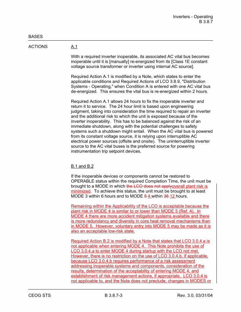
Inverters - Operating B 3.8.7
CEOG STS B 3.8.7-3 Rev. 3.0, 03/31/04
BASES ACTIONS A.1
With a required inverter inoperable, its associated AC vital bus becomes inoperable until it is [manually] re-energized from its [Class 1E constant voltage source transformer or inverter using internal AC source]. Required Action A.1 is modified by a Note, which states to enter the applicable conditions and Required Actions of LCO 3.8.9, "Distribution Systems - Operating," when Condition A is entered with one AC vital bus de-energized. This ensures the vital bus is re-energized within 2 hours. Required Action A.1 allows 24 hours to fix the inoperable inverter and return it to service. The 24 hour limit is based upon engineering judgment, taking into consideration the time required to repair an inverter and the additional risk to which the unit is exposed because of the inverter inoperability. This has to be balanced against the risk of an immediate shutdown, along with the potential challenges to safety systems such a shutdown might entail. When the AC vital bus is powered from its constant voltage source, it is relying upon interruptible AC electrical power sources (offsite and onsite). The uninterruptible inverter source to the AC vital buses is the preferred source for powering instrumentation trip setpoint devices. B.1 and B.2 If the inoperable devices or components cannot be restored to OPERABLE status within the required Completion Time, the unit must be brought to a MODE in which the LCO does not applyoverall plant risk is minimized. To achieve this status, the unit must be brought to at least MODE 3 within 6 hours and to MODE 5 4 within 36 12 hours. Remaining within the Applicability of the LCO is acceptable because the plant risk in MODE 4 is similar to or lower than MODE 5 (Ref. 4). In MODE 4 there are more accident mitigation systems available and there is more redundancy and diversity in core heat removal mechanisms than in MODE 5. However, voluntary entry into MODE 5 may be made as it is also an acceptable low-risk state. Required Action B.2 is modified by a Note that states that LCO 3.0.4.a is not applicable when entering MODE 4. This Note prohibits the use of LCO 3.0.4.a to enter MODE 4 during startup with the LCO not met. However, there is no restriction on the use of LCO 3.0.4.b, if applicable, because LCO 3.0.4.b requires performance of a risk assessment addressing inoperable systems and components, consideration of the results, determination of the acceptability of entering MODE 4, and establishment of risk management actions, if appropriate. LCO 3.0.4 is not applicable to, and the Note does not preclude, changes in MODES or

Inverters - Operating B 3.8.7
CEOG STS B 3.8.7-4 Rev. 3.0, 03/31/04
other specified conditions in the Applicability that are required to comply with ACTIONS or that are part of a shutdown of the unit. The allowed Completion Times are reasonable, based on operating experience, to reach the required unit conditions from full power conditions in an orderly manner and without challenging unit systems.
SURVEILLANCE SR 3.8.7.1 REQUIREMENTS
This Surveillance verifies that the inverters are functioning properly with all required circuit breakers closed and AC vital buses energized from the inverter. The verification of proper voltage and frequency output ensures that the required power is readily available for the instrumentation of the RPS and ESFAS connected to the AC vital buses. The 7 day Frequency takes into account the redundant capability of the inverters and other indications available in the control room that alert the operator to inverter malfunctions.
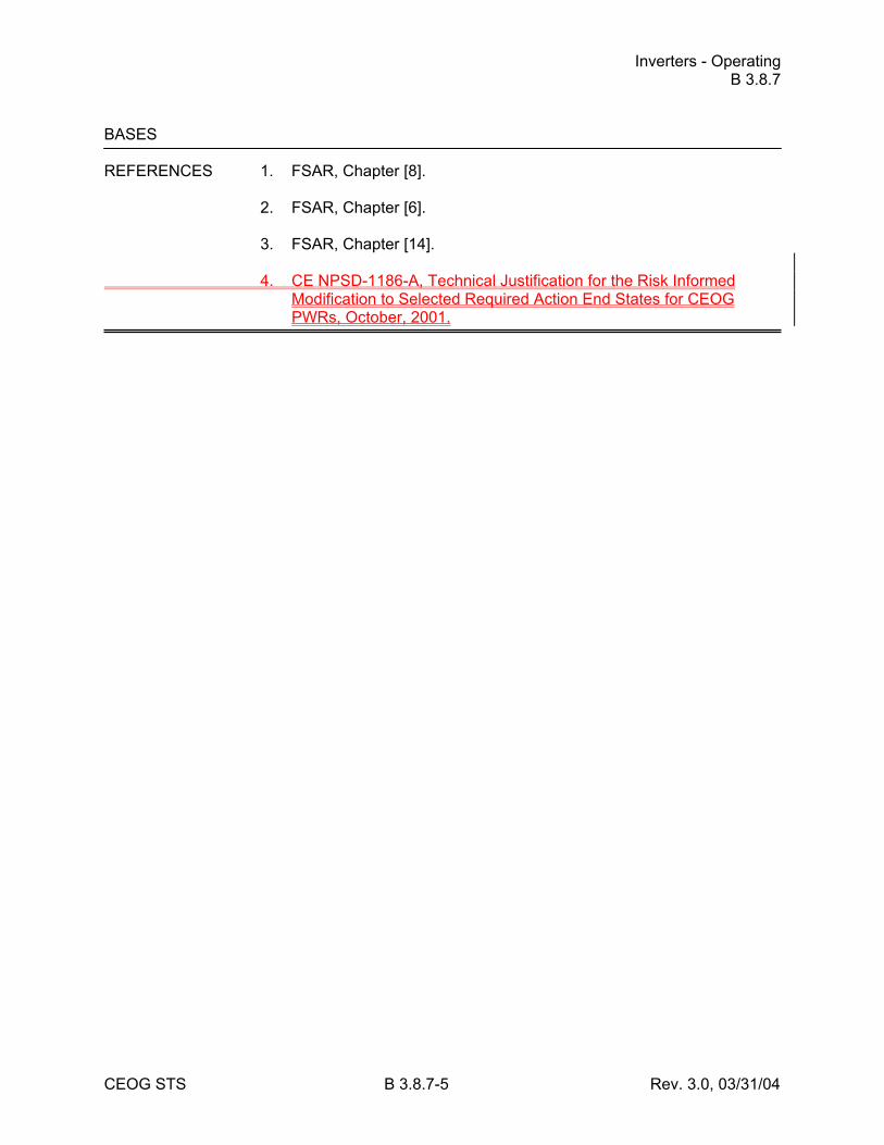
Inverters - Operating B 3.8.7
CEOG STS B 3.8.7-5 Rev. 3.0, 03/31/04
BASES REFERENCES 1. FSAR, Chapter [8]. 2. FSAR, Chapter [6]. 3. FSAR, Chapter [14]. 4. CE NPSD-1186-A, Technical Justification for the Risk Informed
Modification to Selected Required Action End States for CEOG PWRs, October, 2001.
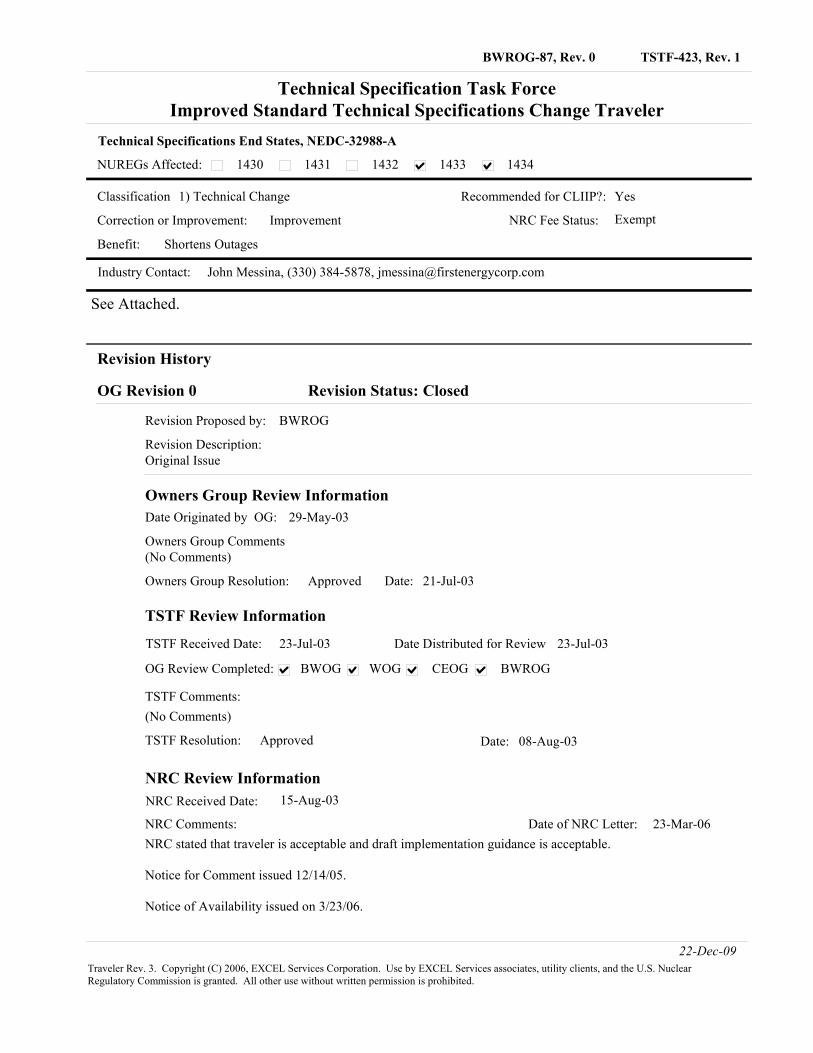
TSTF-423, Rev. 1BWROG-87, Rev. 0
NUREGs Affected:
Technical Specifications End States, NEDC-32988-A
Technical Specification Task ForceImproved Standard Technical Specifications Change Traveler
1430 1431 1432 1433 1434
Classification 1) Technical Change Recommended for CLIIP?:
Industry Contact: John Messina, (330) 384-5878, [email protected]
Yes
Correction or Improvement: Improvement NRC Fee Status: Exempt
Benefit: Shortens Outages
See Attached.
Revision History
OG Revision 0 Revision Status: Closed
Original IssueRevision Description:
Revision Proposed by: BWROG
Owners Group Review InformationDate Originated by OG: 29-May-03
Owners Group Comments(No Comments)
Date: 21-Jul-03Owners Group Resolution: Approved
TSTF Review Information
TSTF Received Date: 23-Jul-03 Date Distributed for Review 23-Jul-03
TSTF Comments:
(No Comments)
Date: 08-Aug-03TSTF Resolution: Approved
OG Review Completed: BWOG CEOGWOG BWROG
NRC Review InformationNRC Received Date: 15-Aug-03
NRC stated that traveler is acceptable and draft implementation guidance is acceptable.
Notice for Comment issued 12/14/05.
Notice of Availability issued on 3/23/06.
NRC Comments: Date of NRC Letter: 23-Mar-06
22-Dec-09Traveler Rev. 3. Copyright (C) 2006, EXCEL Services Corporation. Use by EXCEL Services associates, utility clients, and the U.S. Nuclear Regulatory Commission is granted. All other use without written permission is prohibited.
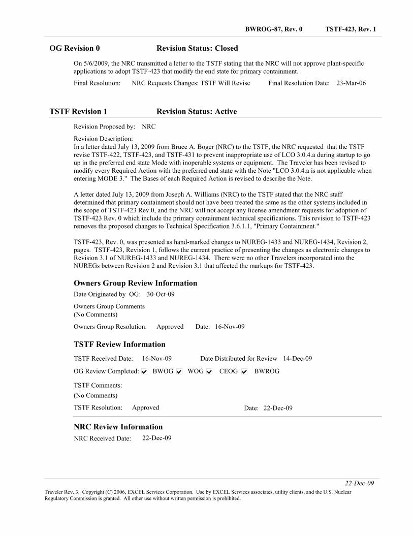
TSTF-423, Rev. 1BWROG-87, Rev. 0
OG Revision 0 Revision Status: Closed
On 5/6/2009, the NRC transmitted a letter to the TSTF stating that the NRC will not approve plant-specific applications to adopt TSTF-423 that modify the end state for primary containment.
23-Mar-06NRC Requests Changes: TSTF Will ReviseFinal Resolution: Final Resolution Date:
TSTF Revision 1 Revision Status: Active
In a letter dated July 13, 2009 from Bruce A. Boger (NRC) to the TSTF, the NRC requested that the TSTF revise TSTF-422, TSTF-423, and TSTF-431 to prevent inappropriate use of LCO 3.0.4.a during startup to go up in the preferred end state Mode with inoperable systems or equipment. The Traveler has been revised to modify every Required Action with the preferred end state with the Note "LCO 3.0.4.a is not applicable when entering MODE 3." The Bases of each Required Action is revised to describe the Note.
A letter dated July 13, 2009 from Joseph A. Williams (NRC) to the TSTF stated that the NRC staff determined that primary containment should not have been treated the same as the other systems included in the scope of TSTF-423 Rev.0, and the NRC will not accept any license amendment requests for adoption of TSTF-423 Rev. 0 which include the primary containment technical specifications. This revision to TSTF-423 removes the proposed changes to Technical Specification 3.6.1.1, "Primary Containment."
TSTF-423, Rev. 0, was presented as hand-marked changes to NUREG-1433 and NUREG-1434, Revision 2, pages. TSTF-423, Revision 1, follows the current practice of presenting the changes as electronic changes to Revision 3.1 of NUREG-1433 and NUREG-1434. There were no other Travelers incorporated into the NUREGs between Revision 2 and Revision 3.1 that affected the markups for TSTF-423.
Revision Description:
Revision Proposed by: NRC
Owners Group Review InformationDate Originated by OG: 30-Oct-09
Owners Group Comments(No Comments)
Date: 16-Nov-09Owners Group Resolution: Approved
TSTF Review Information
TSTF Received Date: 16-Nov-09 Date Distributed for Review 14-Dec-09
TSTF Comments:
(No Comments)
Date: 22-Dec-09TSTF Resolution: Approved
OG Review Completed: BWOG CEOGWOG BWROG
NRC Review InformationNRC Received Date: 22-Dec-09
22-Dec-09Traveler Rev. 3. Copyright (C) 2006, EXCEL Services Corporation. Use by EXCEL Services associates, utility clients, and the U.S. Nuclear Regulatory Commission is granted. All other use without written permission is prohibited.
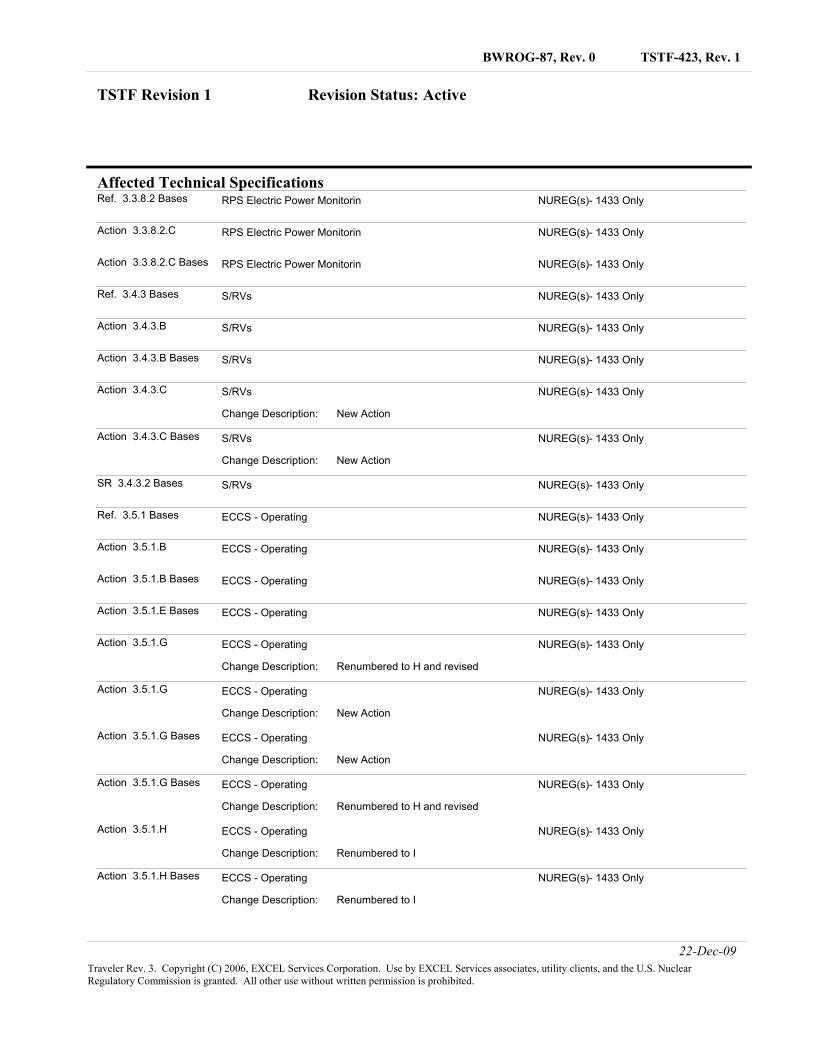
TSTF-423, Rev. 1BWROG-87, Rev. 0
Affected Technical Specifications
TSTF Revision 1 Revision Status: Active
Ref. 3.3.8.2 Bases NUREG(s)- 1433 OnlyRPS Electric Power Monitorin
Action 3.3.8.2.C NUREG(s)- 1433 OnlyRPS Electric Power Monitorin
Action 3.3.8.2.C Bases NUREG(s)- 1433 OnlyRPS Electric Power Monitorin
Ref. 3.4.3 Bases NUREG(s)- 1433 OnlyS/RVs
Action 3.4.3.B NUREG(s)- 1433 OnlyS/RVs
Action 3.4.3.B Bases NUREG(s)- 1433 OnlyS/RVs
Action 3.4.3.C NUREG(s)- 1433 Only
New ActionChange Description:
S/RVs
Action 3.4.3.C Bases NUREG(s)- 1433 Only
New ActionChange Description:
S/RVs
SR 3.4.3.2 Bases NUREG(s)- 1433 OnlyS/RVs
Ref. 3.5.1 Bases NUREG(s)- 1433 OnlyECCS - Operating
Action 3.5.1.B NUREG(s)- 1433 OnlyECCS - Operating
Action 3.5.1.B Bases NUREG(s)- 1433 OnlyECCS - Operating
Action 3.5.1.E Bases NUREG(s)- 1433 OnlyECCS - Operating
Action 3.5.1.G NUREG(s)- 1433 Only
Renumbered to H and revisedChange Description:
ECCS - Operating
Action 3.5.1.G NUREG(s)- 1433 Only
New ActionChange Description:
ECCS - Operating
Action 3.5.1.G Bases NUREG(s)- 1433 Only
New ActionChange Description:
ECCS - Operating
Action 3.5.1.G Bases NUREG(s)- 1433 Only
Renumbered to H and revisedChange Description:
ECCS - Operating
Action 3.5.1.H NUREG(s)- 1433 Only
Renumbered to IChange Description:
ECCS - Operating
Action 3.5.1.H Bases NUREG(s)- 1433 Only
Renumbered to IChange Description:
ECCS - Operating
22-Dec-09Traveler Rev. 3. Copyright (C) 2006, EXCEL Services Corporation. Use by EXCEL Services associates, utility clients, and the U.S. Nuclear Regulatory Commission is granted. All other use without written permission is prohibited.
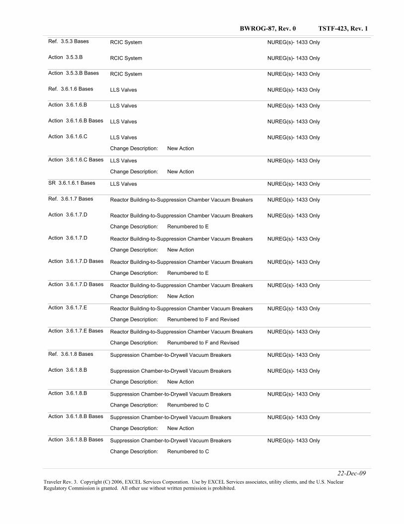
TSTF-423, Rev. 1BWROG-87, Rev. 0
Ref. 3.5.3 Bases NUREG(s)- 1433 OnlyRCIC System
Action 3.5.3.B NUREG(s)- 1433 OnlyRCIC System
Action 3.5.3.B Bases NUREG(s)- 1433 OnlyRCIC System
Ref. 3.6.1.6 Bases NUREG(s)- 1433 OnlyLLS Valves
Action 3.6.1.6.B NUREG(s)- 1433 OnlyLLS Valves
Action 3.6.1.6.B Bases NUREG(s)- 1433 OnlyLLS Valves
Action 3.6.1.6.C NUREG(s)- 1433 Only
New ActionChange Description:
LLS Valves
Action 3.6.1.6.C Bases NUREG(s)- 1433 Only
New ActionChange Description:
LLS Valves
SR 3.6.1.6.1 Bases NUREG(s)- 1433 OnlyLLS Valves
Ref. 3.6.1.7 Bases NUREG(s)- 1433 OnlyReactor Building-to-Suppression Chamber Vacuum Breakers
Action 3.6.1.7.D NUREG(s)- 1433 Only
Renumbered to EChange Description:
Reactor Building-to-Suppression Chamber Vacuum Breakers
Action 3.6.1.7.D NUREG(s)- 1433 Only
New ActionChange Description:
Reactor Building-to-Suppression Chamber Vacuum Breakers
Action 3.6.1.7.D Bases NUREG(s)- 1433 Only
Renumbered to EChange Description:
Reactor Building-to-Suppression Chamber Vacuum Breakers
Action 3.6.1.7.D Bases NUREG(s)- 1433 Only
New ActionChange Description:
Reactor Building-to-Suppression Chamber Vacuum Breakers
Action 3.6.1.7.E NUREG(s)- 1433 Only
Renumbered to F and RevisedChange Description:
Reactor Building-to-Suppression Chamber Vacuum Breakers
Action 3.6.1.7.E Bases NUREG(s)- 1433 Only
Renumbered to F and RevisedChange Description:
Reactor Building-to-Suppression Chamber Vacuum Breakers
Ref. 3.6.1.8 Bases NUREG(s)- 1433 OnlySuppression Chamber-to-Drywell Vacuum Breakers
Action 3.6.1.8.B NUREG(s)- 1433 Only
New ActionChange Description:
Suppression Chamber-to-Drywell Vacuum Breakers
Action 3.6.1.8.B NUREG(s)- 1433 Only
Renumbered to CChange Description:
Suppression Chamber-to-Drywell Vacuum Breakers
Action 3.6.1.8.B Bases NUREG(s)- 1433 Only
New ActionChange Description:
Suppression Chamber-to-Drywell Vacuum Breakers
Action 3.6.1.8.B Bases NUREG(s)- 1433 Only
Renumbered to CChange Description:
Suppression Chamber-to-Drywell Vacuum Breakers
22-Dec-09Traveler Rev. 3. Copyright (C) 2006, EXCEL Services Corporation. Use by EXCEL Services associates, utility clients, and the U.S. Nuclear Regulatory Commission is granted. All other use without written permission is prohibited.
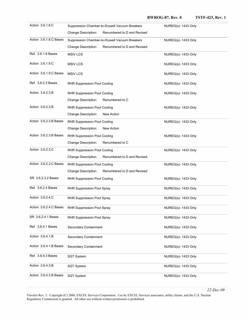
TSTF-423, Rev. 1BWROG-87, Rev. 0
Action 3.6.1.8.C NUREG(s)- 1433 Only
Renumbered to D and RevisedChange Description:
Suppression Chamber-to-Drywell Vacuum Breakers
Action 3.6.1.8.C Bases NUREG(s)- 1433 Only
Renumbered to D and RevisedChange Description:
Suppression Chamber-to-Drywell Vacuum Breakers
Ref. 3.6.1.9 Bases NUREG(s)- 1433 OnlyMSIV LCS
Action 3.6.1.9.C NUREG(s)- 1433 OnlyMSIV LCS
Action 3.6.1.9.C Bases NUREG(s)- 1433 OnlyMSIV LCS
Ref. 3.6.2.3 Bases NUREG(s)- 1433 OnlyRHR Suppression Pool Cooling
Action 3.6.2.3.B NUREG(s)- 1433 Only
Renumbered to CChange Description:
RHR Suppression Pool Cooling
Action 3.6.2.3.B NUREG(s)- 1433 Only
New ActionChange Description:
RHR Suppression Pool Cooling
Action 3.6.2.3.B Bases NUREG(s)- 1433 Only
New ActionChange Description:
RHR Suppression Pool Cooling
Action 3.6.2.3.B Bases NUREG(s)- 1433 Only
Renumbered to CChange Description:
RHR Suppression Pool Cooling
Action 3.6.2.3.C NUREG(s)- 1433 Only
Renumbered to D and RevisedChange Description:
RHR Suppression Pool Cooling
Action 3.6.2.3.C Bases NUREG(s)- 1433 Only
Renumbered to D and RevisedChange Description:
RHR Suppression Pool Cooling
SR 3.6.2.3.2 Bases NUREG(s)- 1433 OnlyRHR Suppression Pool Cooling
Ref. 3.6.2.4 Bases NUREG(s)- 1433 OnlyRHR Suppression Pool Spray
Action 3.6.2.4.C NUREG(s)- 1433 OnlyRHR Suppression Pool Spray
Action 3.6.2.4.C Bases NUREG(s)- 1433 OnlyRHR Suppression Pool Spray
SR 3.6.2.4.1 Bases NUREG(s)- 1433 OnlyRHR Suppression Pool Spray
Ref. 3.6.4.1 Bases NUREG(s)- 1433 OnlySecondary Containment
Action 3.6.4.1.B NUREG(s)- 1433 OnlySecondary Containment
Action 3.6.4.1.B Bases NUREG(s)- 1433 OnlySecondary Containment
Ref. 3.6.4.3 Bases NUREG(s)- 1433 OnlySGT System
Action 3.6.4.3.B NUREG(s)- 1433 OnlySGT System
Action 3.6.4.3.B Bases NUREG(s)- 1433 OnlySGT System
22-Dec-09Traveler Rev. 3. Copyright (C) 2006, EXCEL Services Corporation. Use by EXCEL Services associates, utility clients, and the U.S. Nuclear Regulatory Commission is granted. All other use without written permission is prohibited.
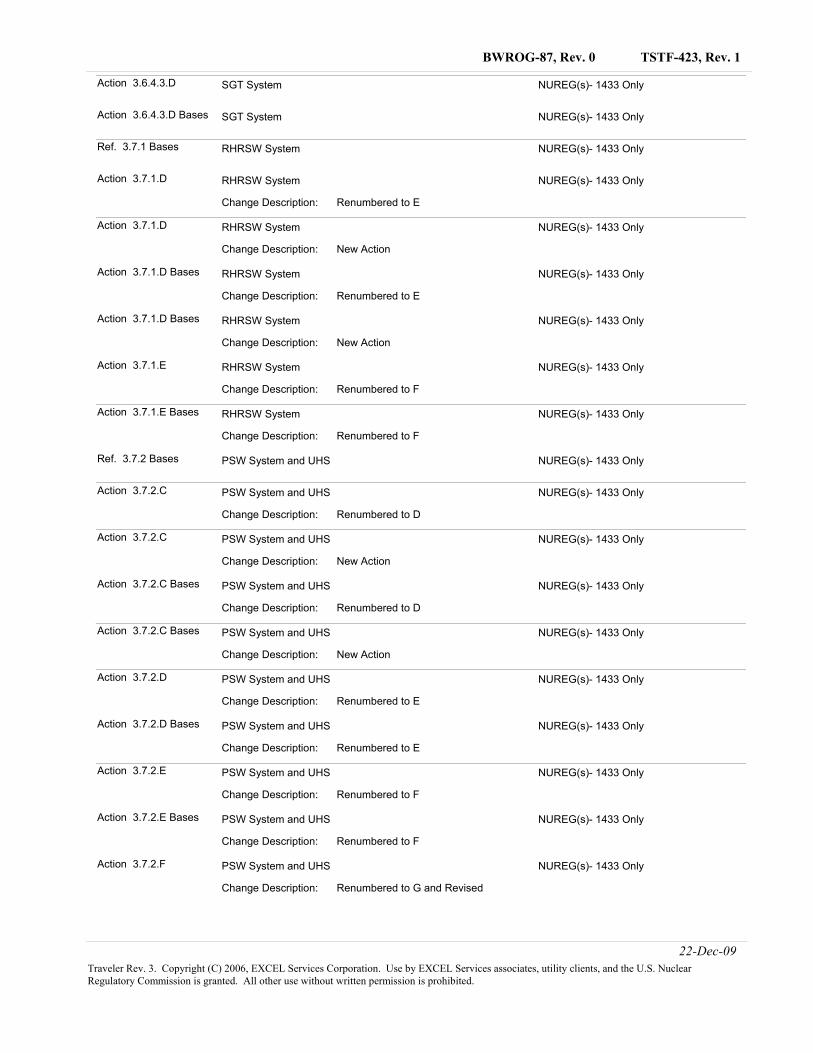
TSTF-423, Rev. 1BWROG-87, Rev. 0
Action 3.6.4.3.D NUREG(s)- 1433 OnlySGT System
Action 3.6.4.3.D Bases NUREG(s)- 1433 OnlySGT System
Ref. 3.7.1 Bases NUREG(s)- 1433 OnlyRHRSW System
Action 3.7.1.D NUREG(s)- 1433 Only
Renumbered to EChange Description:
RHRSW System
Action 3.7.1.D NUREG(s)- 1433 Only
New ActionChange Description:
RHRSW System
Action 3.7.1.D Bases NUREG(s)- 1433 Only
Renumbered to EChange Description:
RHRSW System
Action 3.7.1.D Bases NUREG(s)- 1433 Only
New ActionChange Description:
RHRSW System
Action 3.7.1.E NUREG(s)- 1433 Only
Renumbered to FChange Description:
RHRSW System
Action 3.7.1.E Bases NUREG(s)- 1433 Only
Renumbered to FChange Description:
RHRSW System
Ref. 3.7.2 Bases NUREG(s)- 1433 OnlyPSW System and UHS
Action 3.7.2.C NUREG(s)- 1433 Only
Renumbered to DChange Description:
PSW System and UHS
Action 3.7.2.C NUREG(s)- 1433 Only
New ActionChange Description:
PSW System and UHS
Action 3.7.2.C Bases NUREG(s)- 1433 Only
Renumbered to DChange Description:
PSW System and UHS
Action 3.7.2.C Bases NUREG(s)- 1433 Only
New ActionChange Description:
PSW System and UHS
Action 3.7.2.D NUREG(s)- 1433 Only
Renumbered to EChange Description:
PSW System and UHS
Action 3.7.2.D Bases NUREG(s)- 1433 Only
Renumbered to EChange Description:
PSW System and UHS
Action 3.7.2.E NUREG(s)- 1433 Only
Renumbered to FChange Description:
PSW System and UHS
Action 3.7.2.E Bases NUREG(s)- 1433 Only
Renumbered to FChange Description:
PSW System and UHS
Action 3.7.2.F NUREG(s)- 1433 Only
Renumbered to G and RevisedChange Description:
PSW System and UHS
22-Dec-09Traveler Rev. 3. Copyright (C) 2006, EXCEL Services Corporation. Use by EXCEL Services associates, utility clients, and the U.S. Nuclear Regulatory Commission is granted. All other use without written permission is prohibited.
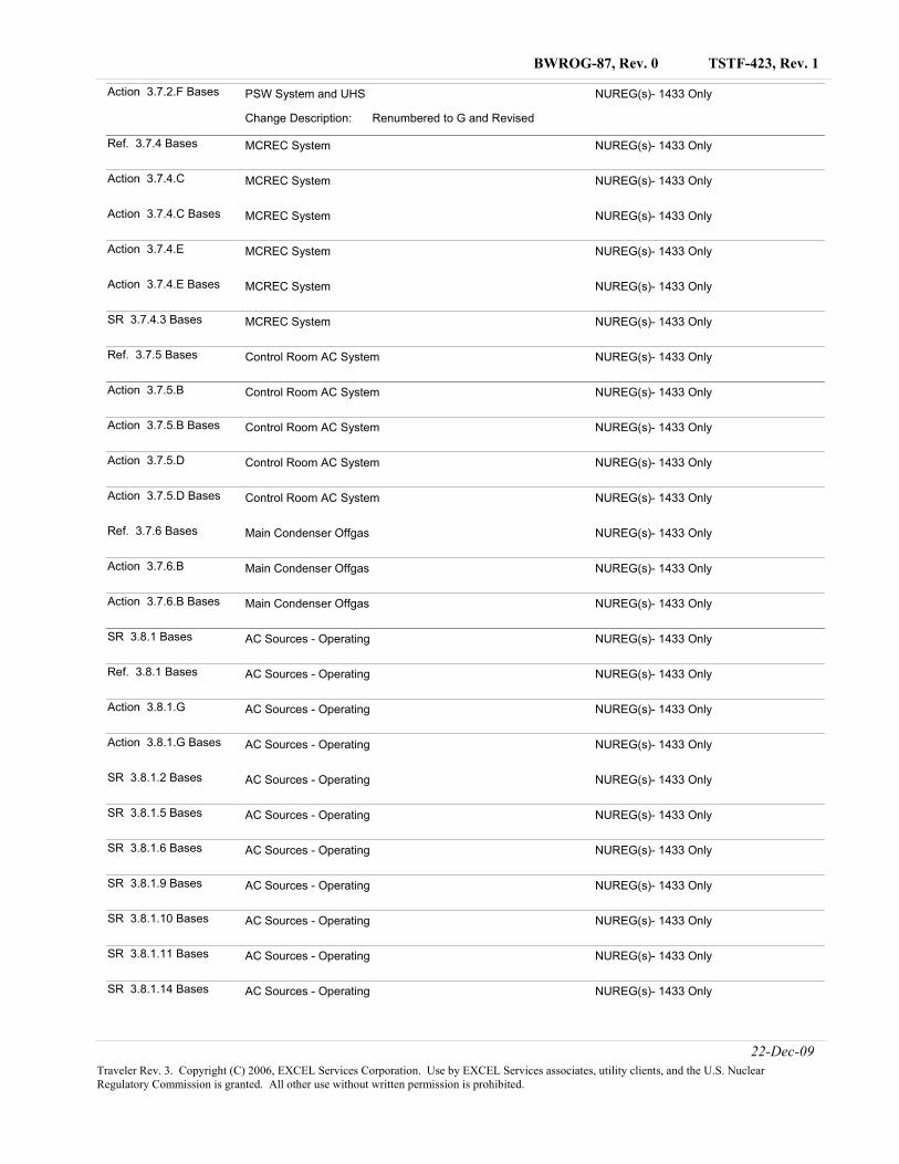
TSTF-423, Rev. 1BWROG-87, Rev. 0
Action 3.7.2.F Bases NUREG(s)- 1433 Only
Renumbered to G and RevisedChange Description:
PSW System and UHS
Ref. 3.7.4 Bases NUREG(s)- 1433 OnlyMCREC System
Action 3.7.4.C NUREG(s)- 1433 OnlyMCREC System
Action 3.7.4.C Bases NUREG(s)- 1433 OnlyMCREC System
Action 3.7.4.E NUREG(s)- 1433 OnlyMCREC System
Action 3.7.4.E Bases NUREG(s)- 1433 OnlyMCREC System
SR 3.7.4.3 Bases NUREG(s)- 1433 OnlyMCREC System
Ref. 3.7.5 Bases NUREG(s)- 1433 OnlyControl Room AC System
Action 3.7.5.B NUREG(s)- 1433 OnlyControl Room AC System
Action 3.7.5.B Bases NUREG(s)- 1433 OnlyControl Room AC System
Action 3.7.5.D NUREG(s)- 1433 OnlyControl Room AC System
Action 3.7.5.D Bases NUREG(s)- 1433 OnlyControl Room AC System
Ref. 3.7.6 Bases NUREG(s)- 1433 OnlyMain Condenser Offgas
Action 3.7.6.B NUREG(s)- 1433 OnlyMain Condenser Offgas
Action 3.7.6.B Bases NUREG(s)- 1433 OnlyMain Condenser Offgas
SR 3.8.1 Bases NUREG(s)- 1433 OnlyAC Sources - Operating
Ref. 3.8.1 Bases NUREG(s)- 1433 OnlyAC Sources - Operating
Action 3.8.1.G NUREG(s)- 1433 OnlyAC Sources - Operating
Action 3.8.1.G Bases NUREG(s)- 1433 OnlyAC Sources - Operating
SR 3.8.1.2 Bases NUREG(s)- 1433 OnlyAC Sources - Operating
SR 3.8.1.5 Bases NUREG(s)- 1433 OnlyAC Sources - Operating
SR 3.8.1.6 Bases NUREG(s)- 1433 OnlyAC Sources - Operating
SR 3.8.1.9 Bases NUREG(s)- 1433 OnlyAC Sources - Operating
SR 3.8.1.10 Bases NUREG(s)- 1433 OnlyAC Sources - Operating
SR 3.8.1.11 Bases NUREG(s)- 1433 OnlyAC Sources - Operating
SR 3.8.1.14 Bases NUREG(s)- 1433 OnlyAC Sources - Operating
22-Dec-09Traveler Rev. 3. Copyright (C) 2006, EXCEL Services Corporation. Use by EXCEL Services associates, utility clients, and the U.S. Nuclear Regulatory Commission is granted. All other use without written permission is prohibited.
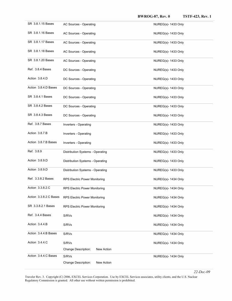
TSTF-423, Rev. 1BWROG-87, Rev. 0
SR 3.8.1.15 Bases NUREG(s)- 1433 OnlyAC Sources - Operating
SR 3.8.1.16 Bases NUREG(s)- 1433 OnlyAC Sources - Operating
SR 3.8.1.17 Bases NUREG(s)- 1433 OnlyAC Sources - Operating
SR 3.8.1.18 Bases NUREG(s)- 1433 OnlyAC Sources - Operating
SR 3.8.1.20 Bases NUREG(s)- 1433 OnlyAC Sources - Operating
Ref. 3.8.4 Bases NUREG(s)- 1433 OnlyDC Sources - Operating
Action 3.8.4.D NUREG(s)- 1433 OnlyDC Sources - Operating
Action 3.8.4.D Bases NUREG(s)- 1433 OnlyDC Sources - Operating
SR 3.8.4.1 Bases NUREG(s)- 1433 OnlyDC Sources - Operating
SR 3.8.4.2 Bases NUREG(s)- 1433 OnlyDC Sources - Operating
SR 3.8.4.3 Bases NUREG(s)- 1433 OnlyDC Sources - Operating
Ref. 3.8.7 Bases NUREG(s)- 1433 OnlyInverters - Operating
Action 3.8.7.B NUREG(s)- 1433 OnlyInverters - Operating
Action 3.8.7.B Bases NUREG(s)- 1433 OnlyInverters - Operating
Ref. 3.8.9 NUREG(s)- 1433 OnlyDistribution Systems - Operating
Action 3.8.9.D NUREG(s)- 1433 OnlyDistribution Systems - Operating
Action 3.8.9.D NUREG(s)- 1433 OnlyDistribution Systems - Operating
Ref. 3.3.8.2 Bases NUREG(s)- 1434 OnlyRPS Electric Power Monitoring
Action 3.3.8.2.C NUREG(s)- 1434 OnlyRPS Electric Power Monitoring
Action 3.3.8.2.C Bases NUREG(s)- 1434 OnlyRPS Electric Power Monitoring
SR 3.3.8.2.1 Bases NUREG(s)- 1434 OnlyRPS Electric Power Monitoring
Ref. 3.4.4 Bases NUREG(s)- 1434 OnlyS/RVs
Action 3.4.4.B NUREG(s)- 1434 OnlyS/RVs
Action 3.4.4.B Bases NUREG(s)- 1434 OnlyS/RVs
Action 3.4.4.C NUREG(s)- 1434 Only
New ActionChange Description:
S/RVs
Action 3.4.4.C Bases NUREG(s)- 1434 Only
New ActionChange Description:
S/RVs
22-Dec-09Traveler Rev. 3. Copyright (C) 2006, EXCEL Services Corporation. Use by EXCEL Services associates, utility clients, and the U.S. Nuclear Regulatory Commission is granted. All other use without written permission is prohibited.
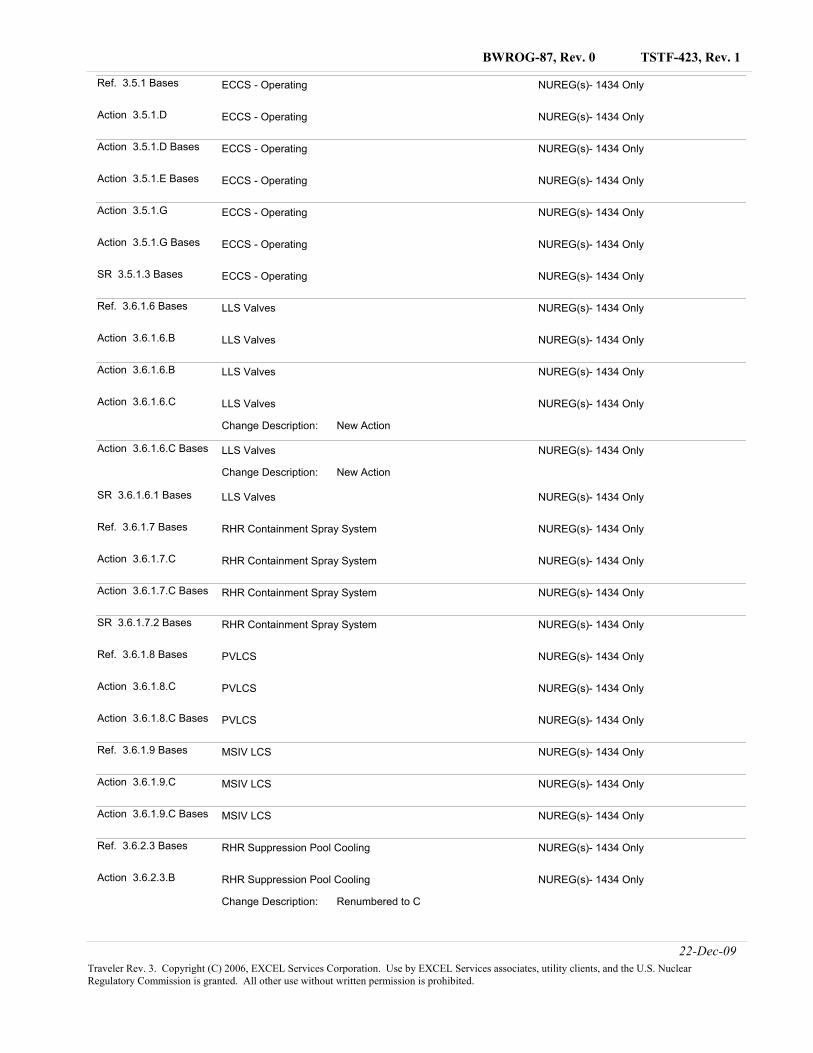
TSTF-423, Rev. 1BWROG-87, Rev. 0
Ref. 3.5.1 Bases NUREG(s)- 1434 OnlyECCS - Operating
Action 3.5.1.D NUREG(s)- 1434 OnlyECCS - Operating
Action 3.5.1.D Bases NUREG(s)- 1434 OnlyECCS - Operating
Action 3.5.1.E Bases NUREG(s)- 1434 OnlyECCS - Operating
Action 3.5.1.G NUREG(s)- 1434 OnlyECCS - Operating
Action 3.5.1.G Bases NUREG(s)- 1434 OnlyECCS - Operating
SR 3.5.1.3 Bases NUREG(s)- 1434 OnlyECCS - Operating
Ref. 3.6.1.6 Bases NUREG(s)- 1434 OnlyLLS Valves
Action 3.6.1.6.B NUREG(s)- 1434 OnlyLLS Valves
Action 3.6.1.6.B NUREG(s)- 1434 OnlyLLS Valves
Action 3.6.1.6.C NUREG(s)- 1434 Only
New ActionChange Description:
LLS Valves
Action 3.6.1.6.C Bases NUREG(s)- 1434 Only
New ActionChange Description:
LLS Valves
SR 3.6.1.6.1 Bases NUREG(s)- 1434 OnlyLLS Valves
Ref. 3.6.1.7 Bases NUREG(s)- 1434 OnlyRHR Containment Spray System
Action 3.6.1.7.C NUREG(s)- 1434 OnlyRHR Containment Spray System
Action 3.6.1.7.C Bases NUREG(s)- 1434 OnlyRHR Containment Spray System
SR 3.6.1.7.2 Bases NUREG(s)- 1434 OnlyRHR Containment Spray System
Ref. 3.6.1.8 Bases NUREG(s)- 1434 OnlyPVLCS
Action 3.6.1.8.C NUREG(s)- 1434 OnlyPVLCS
Action 3.6.1.8.C Bases NUREG(s)- 1434 OnlyPVLCS
Ref. 3.6.1.9 Bases NUREG(s)- 1434 OnlyMSIV LCS
Action 3.6.1.9.C NUREG(s)- 1434 OnlyMSIV LCS
Action 3.6.1.9.C Bases NUREG(s)- 1434 OnlyMSIV LCS
Ref. 3.6.2.3 Bases NUREG(s)- 1434 OnlyRHR Suppression Pool Cooling
Action 3.6.2.3.B NUREG(s)- 1434 Only
Renumbered to CChange Description:
RHR Suppression Pool Cooling
22-Dec-09Traveler Rev. 3. Copyright (C) 2006, EXCEL Services Corporation. Use by EXCEL Services associates, utility clients, and the U.S. Nuclear Regulatory Commission is granted. All other use without written permission is prohibited.
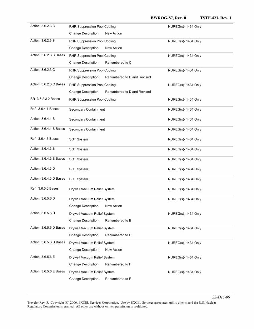
TSTF-423, Rev. 1BWROG-87, Rev. 0
Action 3.6.2.3.B NUREG(s)- 1434 Only
New ActionChange Description:
RHR Suppression Pool Cooling
Action 3.6.2.3.B NUREG(s)- 1434 Only
New ActionChange Description:
RHR Suppression Pool Cooling
Action 3.6.2.3.B Bases NUREG(s)- 1434 Only
Renumbered to CChange Description:
RHR Suppression Pool Cooling
Action 3.6.2.3.C NUREG(s)- 1434 Only
Renumbered to D and RevisedChange Description:
RHR Suppression Pool Cooling
Action 3.6.2.3.C Bases NUREG(s)- 1434 Only
Renumbered to D and RevisedChange Description:
RHR Suppression Pool Cooling
SR 3.6.2.3.2 Bases NUREG(s)- 1434 OnlyRHR Suppression Pool Cooling
Ref. 3.6.4.1 Bases NUREG(s)- 1434 OnlySecondary Containment
Action 3.6.4.1.B NUREG(s)- 1434 OnlySecondary Containment
Action 3.6.4.1.B Bases NUREG(s)- 1434 OnlySecondary Containment
Ref. 3.6.4.3 Bases NUREG(s)- 1434 OnlySGT System
Action 3.6.4.3.B NUREG(s)- 1434 OnlySGT System
Action 3.6.4.3.B Bases NUREG(s)- 1434 OnlySGT System
Action 3.6.4.3.D NUREG(s)- 1434 OnlySGT System
Action 3.6.4.3.D Bases NUREG(s)- 1434 OnlySGT System
Ref. 3.6.5.6 Bases NUREG(s)- 1434 OnlyDrywell Vacuum Relief System
Action 3.6.5.6.D NUREG(s)- 1434 Only
New ActionChange Description:
Drywell Vacuum Relief System
Action 3.6.5.6.D NUREG(s)- 1434 Only
Renumbered to EChange Description:
Drywell Vacuum Relief System
Action 3.6.5.6.D Bases NUREG(s)- 1434 Only
Renumbered to EChange Description:
Drywell Vacuum Relief System
Action 3.6.5.6.D Bases NUREG(s)- 1434 Only
New ActionChange Description:
Drywell Vacuum Relief System
Action 3.6.5.6.E NUREG(s)- 1434 Only
Renumbered to FChange Description:
Drywell Vacuum Relief System
Action 3.6.5.6.E Bases NUREG(s)- 1434 Only
Renumbered to FChange Description:
Drywell Vacuum Relief System
22-Dec-09Traveler Rev. 3. Copyright (C) 2006, EXCEL Services Corporation. Use by EXCEL Services associates, utility clients, and the U.S. Nuclear Regulatory Commission is granted. All other use without written permission is prohibited.
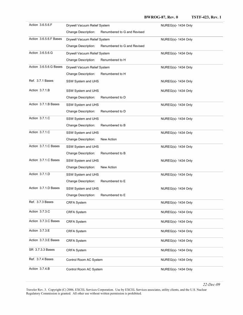
TSTF-423, Rev. 1BWROG-87, Rev. 0
Action 3.6.5.6.F NUREG(s)- 1434 Only
Renumbered to G and RevisedChange Description:
Drywell Vacuum Relief System
Action 3.6.5.6.F Bases NUREG(s)- 1434 Only
Renumbered to G and RevisedChange Description:
Drywell Vacuum Relief System
Action 3.6.5.6.G NUREG(s)- 1434 Only
Renumbered to HChange Description:
Drywell Vacuum Relief System
Action 3.6.5.6.G Bases NUREG(s)- 1434 Only
Renumbered to HChange Description:
Drywell Vacuum Relief System
Ref. 3.7.1 Bases NUREG(s)- 1434 OnlySSW System and UHS
Action 3.7.1.B NUREG(s)- 1434 Only
Renumbered to DChange Description:
SSW System and UHS
Action 3.7.1.B Bases NUREG(s)- 1434 Only
Renumbered to DChange Description:
SSW System and UHS
Action 3.7.1.C NUREG(s)- 1434 Only
Renumbered to BChange Description:
SSW System and UHS
Action 3.7.1.C NUREG(s)- 1434 Only
New ActionChange Description:
SSW System and UHS
Action 3.7.1.C Bases NUREG(s)- 1434 Only
Renumbered to BChange Description:
SSW System and UHS
Action 3.7.1.C Bases NUREG(s)- 1434 Only
New ActionChange Description:
SSW System and UHS
Action 3.7.1.D NUREG(s)- 1434 Only
Renumbered to EChange Description:
SSW System and UHS
Action 3.7.1.D Bases NUREG(s)- 1434 Only
Renumbered to EChange Description:
SSW System and UHS
Ref. 3.7.3 Bases NUREG(s)- 1434 OnlyCRFA System
Action 3.7.3.C NUREG(s)- 1434 OnlyCRFA System
Action 3.7.3.C Bases NUREG(s)- 1434 OnlyCRFA System
Action 3.7.3.E NUREG(s)- 1434 OnlyCRFA System
Action 3.7.3.E Bases NUREG(s)- 1434 OnlyCRFA System
SR 3.7.3.3 Bases NUREG(s)- 1434 OnlyCRFA System
Ref. 3.7.4 Bases NUREG(s)- 1434 OnlyControl Room AC System
Action 3.7.4.B NUREG(s)- 1434 OnlyControl Room AC System
22-Dec-09Traveler Rev. 3. Copyright (C) 2006, EXCEL Services Corporation. Use by EXCEL Services associates, utility clients, and the U.S. Nuclear Regulatory Commission is granted. All other use without written permission is prohibited.
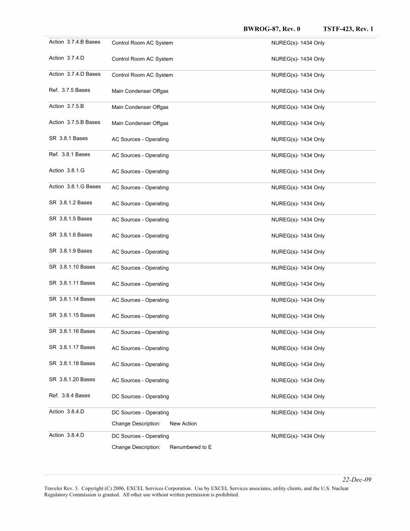
TSTF-423, Rev. 1BWROG-87, Rev. 0
Action 3.7.4.B Bases NUREG(s)- 1434 OnlyControl Room AC System
Action 3.7.4.D NUREG(s)- 1434 OnlyControl Room AC System
Action 3.7.4.D Bases NUREG(s)- 1434 OnlyControl Room AC System
Ref. 3.7.5 Bases NUREG(s)- 1434 OnlyMain Condenser Offgas
Action 3.7.5.B NUREG(s)- 1434 OnlyMain Condenser Offgas
Action 3.7.5.B Bases NUREG(s)- 1434 OnlyMain Condenser Offgas
SR 3.8.1 Bases NUREG(s)- 1434 OnlyAC Sources - Operating
Ref. 3.8.1 Bases NUREG(s)- 1434 OnlyAC Sources - Operating
Action 3.8.1.G NUREG(s)- 1434 OnlyAC Sources - Operating
Action 3.8.1.G Bases NUREG(s)- 1434 OnlyAC Sources - Operating
SR 3.8.1.2 Bases NUREG(s)- 1434 OnlyAC Sources - Operating
SR 3.8.1.5 Bases NUREG(s)- 1434 OnlyAC Sources - Operating
SR 3.8.1.6 Bases NUREG(s)- 1434 OnlyAC Sources - Operating
SR 3.8.1.9 Bases NUREG(s)- 1434 OnlyAC Sources - Operating
SR 3.8.1.10 Bases NUREG(s)- 1434 OnlyAC Sources - Operating
SR 3.8.1.11 Bases NUREG(s)- 1434 OnlyAC Sources - Operating
SR 3.8.1.14 Bases NUREG(s)- 1434 OnlyAC Sources - Operating
SR 3.8.1.15 Bases NUREG(s)- 1434 OnlyAC Sources - Operating
SR 3.8.1.16 Bases NUREG(s)- 1434 OnlyAC Sources - Operating
SR 3.8.1.17 Bases NUREG(s)- 1434 OnlyAC Sources - Operating
SR 3.8.1.18 Bases NUREG(s)- 1434 OnlyAC Sources - Operating
SR 3.8.1.20 Bases NUREG(s)- 1434 OnlyAC Sources - Operating
Ref. 3.8.4 Bases NUREG(s)- 1434 OnlyDC Sources - Operating
Action 3.8.4.D NUREG(s)- 1434 Only
New ActionChange Description:
DC Sources - Operating
Action 3.8.4.D NUREG(s)- 1434 Only
Renumbered to EChange Description:
DC Sources - Operating
22-Dec-09Traveler Rev. 3. Copyright (C) 2006, EXCEL Services Corporation. Use by EXCEL Services associates, utility clients, and the U.S. Nuclear Regulatory Commission is granted. All other use without written permission is prohibited.
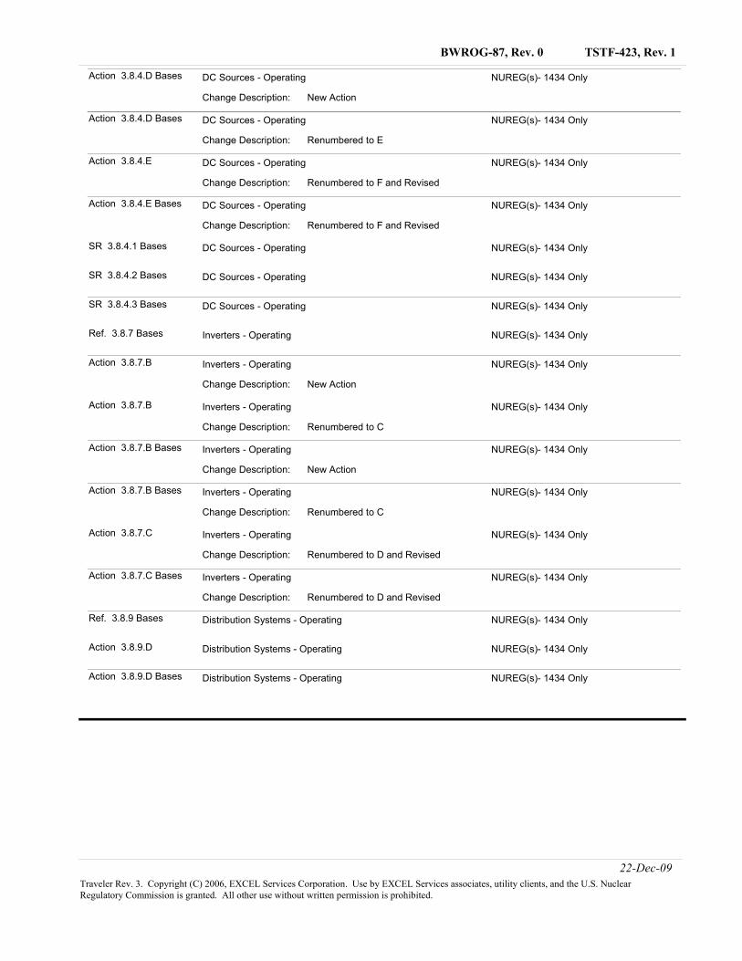
TSTF-423, Rev. 1BWROG-87, Rev. 0
Action 3.8.4.D Bases NUREG(s)- 1434 Only
New ActionChange Description:
DC Sources - Operating
Action 3.8.4.D Bases NUREG(s)- 1434 Only
Renumbered to EChange Description:
DC Sources - Operating
Action 3.8.4.E NUREG(s)- 1434 Only
Renumbered to F and RevisedChange Description:
DC Sources - Operating
Action 3.8.4.E Bases NUREG(s)- 1434 Only
Renumbered to F and RevisedChange Description:
DC Sources - Operating
SR 3.8.4.1 Bases NUREG(s)- 1434 OnlyDC Sources - Operating
SR 3.8.4.2 Bases NUREG(s)- 1434 OnlyDC Sources - Operating
SR 3.8.4.3 Bases NUREG(s)- 1434 OnlyDC Sources - Operating
Ref. 3.8.7 Bases NUREG(s)- 1434 OnlyInverters - Operating
Action 3.8.7.B NUREG(s)- 1434 Only
New ActionChange Description:
Inverters - Operating
Action 3.8.7.B NUREG(s)- 1434 Only
Renumbered to CChange Description:
Inverters - Operating
Action 3.8.7.B Bases NUREG(s)- 1434 Only
New ActionChange Description:
Inverters - Operating
Action 3.8.7.B Bases NUREG(s)- 1434 Only
Renumbered to CChange Description:
Inverters - Operating
Action 3.8.7.C NUREG(s)- 1434 Only
Renumbered to D and RevisedChange Description:
Inverters - Operating
Action 3.8.7.C Bases NUREG(s)- 1434 Only
Renumbered to D and RevisedChange Description:
Inverters - Operating
Ref. 3.8.9 Bases NUREG(s)- 1434 OnlyDistribution Systems - Operating
Action 3.8.9.D NUREG(s)- 1434 OnlyDistribution Systems - Operating
Action 3.8.9.D Bases NUREG(s)- 1434 OnlyDistribution Systems - Operating
22-Dec-09Traveler Rev. 3. Copyright (C) 2006, EXCEL Services Corporation. Use by EXCEL Services associates, utility clients, and the U.S. Nuclear Regulatory Commission is granted. All other use without written permission is prohibited.
TSTF-423, Rev. 1
Page 1
1.0 Description Topical Report NEDC-32988-A, “Technical Justification to Support Risk-Informed Modification to Selected Required Action End States for BWR Plants,” Revision 2, December 2002, (Reference 1) justified modifying the Technical Specifications end state for selected Required Actions in NUREG-1433, “Standard Technical Specifications for BWR/4 Plants,” and NUREG-1434, “Standard Technical Specifications for BWR/6 Plants.” These Required Actions are modified to allow the plant to stay in MODE 3. The Topical Report was approved in a letter from the NRC to Jack Gray, Chairman of the BWR Owners Group, dated September 27, 2002, entitled, “Safety Evaluation of Topical Report NEDC-32988, Rev. 2, ‘Technical Justification to Support Risk-Informed Modification to Selected Required Action End States for BWR Plants,’ (TAC No. MB1054)” (Reference 2). This Traveler implements the changes justified in the Topical Report and approved in the Safety Evaluation. In addition, the revised Required Actions are also modified by a Note that prohibits the use of the provisions of LCO 3.0.4.a to enter the end state Mode within the Applicability during startup. 2.0 Proposed Change The Topical Report and Safety Evaluation describe changes to 22 Technical Specifications in NUREG-1433, which apply to BWR/4 plants, and 20 Technical Specifications in NUREG-1434, which apply to BWR/6 plants. The affected Specifications are listed in Table 1. Appropriate Bases changes are also made to reflect the changes to the Specifications. As new references are added to the Bases, existing references are renumbered as necessary so that the numeric order of the references in the “References” subsection matches the order of their discussion in the text. This is consistent with Section 4.2.1.g of NEI 01-03, “Writer’s Guide for the Improved Standard Technical Specifications.” Revision 1 of TSTF-423 makes the following changes: 1. In a letter dated July 13, 2009 from Bruce A. Boger (NRC) to the TSTF, the NRC requested
that the TSTF revise TSTF-422, TSTF-423, and TSTF-431 to prevent inappropriate use of LCO 3.0.4.a during startup to go up in the preferred end state Mode with inoperable systems or equipment. The Traveler has been revised to modify every Required Action with the preferred end state with the Note "LCO 3.0.4.a is not applicable when entering MODE 3." The Bases of each Required Action is revised to describe the Note.
2. A letter dated July 13, 2009 from Joseph A. Williams (NRC) to the TSTF stated that the
NRC staff determined that primary containment should not have been treated the same as the other systems included in the scope of TSTF-423 Rev.0, and the NRC will not accept any license amendment requests for adoption of TSTF-423 Rev. 0 which include the primary containment technical specifications. This revision to TSTF-423 removes the proposed changes to Technical Specification 3.6.1.1, "Primary Containment."
TSTF-423, Rev. 1
Page 2
3. TSTF-423, Rev. 0, was presented as hand-marked changes to NUREG-1433 and NUREG-1434, Revision 2, pages. TSTF-423, Revision 1, follows the current practice of presenting the changes as electronic changes to Revision 3.1 of NUREG-1433 and NUREG-1434. There were no other Travelers incorporated into the NUREGs between Revision 2 and Revision 3.1 that affected the markups for TSTF-423.
3.0 Background NEDC-32988-A justified the modification of 42 Technical Specifications Required Action end states. The modified end states allow the plant to remain in MODE 3 instead of going to MODE 4 or to MODE 3 with steam dome pressure ≤ 150 psig. 4.0 Technical Analysis The Topical Report provides a systematic review of the risks associated with all Required Actions in Technical Specifications ending in placing the unit in cold shutdown (MODE 4). Cold shutdown is normally required when an inoperable system or train cannot be restored to an OPERABLE status within the allowed time. However, going to cold shutdown results in the loss of steam-driven core cooling systems, challenges the shutdown heat removal systems, and requires restarting the plant over a greater range of plant conditions. A more preferred operational MODE is one that maintains adequate risk levels while repairs are completed without causing unnecessary challenges to plant equipment during shutdown and startup transitions. The Topical Report analysis considered hot shutdown (MODE 3) as a preferred alternative to cold shutdown.
The risks during the two MODES of operation were evaluated using the Probabilistic Safety Analysis (PSA) for a typical BWR-4 plant, but the results are applicable for all the BWR models (BWR-2 through 6). The plant-specific PSA model was modified to evaluate the core damage frequency (CDF) during MODE 3 and MODE 4 operations. This allowed a comparison of the risks between the two shutdown MODES for various inoperable conditions specified in Technical Specifications. In addition to the quantitative analysis, the two MODES of operation were evaluated based on defense-in-depth considerations. The Topical Report demonstrates that, for the modified conditions, remaining in MODE 3 is appropriate for the primary purpose of performing the short-duration repairs needed to correct the failure which necessitated exiting the original operating MODE. In response to the Staffs’ questions, the BWROG stated that "The BWRs are most likely to stay in hot shutdown for no more than 2 to 3 days and definitely, not more than a week." In the Safety Evaluation, the staff stated that they expect that the licensees will follow this guidance. The proposed changes to NUREG-1433 and NUREG-1434 are consistent with the justification presented in the Topical Report as approved by the Safety Evaluation. In some cases, there are editorial differences between the changes described in the Topical Report and Safety Evaluation and the changes made to NUREG-1433 and NUREG-1434. These differences are described in Notes to Table 1. In all cases, the changes made to NUREG-1433 and NUREG-1434 are consistent with the justification presented in the Topical Report and the approval in the Safety Evaluation.
TSTF-423, Rev. 1
Page 3
The revised Required Actions are also modified by the addition of a Note prohibiting entry into the end state Mode within the Applicability during startup using the provisions of LCO 3.0.4.a. The purpose of this Note is to provide assurance that entry into the end state Mode during startup is not made without the appropriate risk assessment. Entry into the end state Mode during startup will still be allowed under the provisions of LCO 3.0.4.b. This is acceptable because LCO 3.0.4.b allows entry only after performance of a risk assessment addressing inoperable systems and components, consideration of the results, determination of the acceptability of entering the MODE or other specified condition in the Applicability, and establishment of risk management actions, if appropriate. Details of the risk assessment are provided in the Bases for LCO 3.0.4.b. The letter transmitting the Safety Evaluation (Reference 2) states, “Licensees requesting a license amendment to revise their end states must include in their amendment requests plant-specific information addressing the stipulations identified in Section 7.0 of the SE.” These stipulations have been addressed in this Traveler as discussed in Table 2.
TSTF-423, Rev. 1
Page 4
5.0 Regulatory Analysis 5.1 No Significant Hazards Consideration The Technical Specification Task Force (TSTF) has evaluated whether or not a significant hazards consideration is involved with the proposed generic change by focusing on the three standards set forth in 10 CFR 50.92, “Issuance of amendment,” as discussed below:
1. Does the proposed change involve a significant increase in the probability or consequences of an accident previously evaluated?
Response: No.
Required Actions are not an initiator of any accident previously evaluated. Therefore, the proposed changes do not affect the probability of any accident previously evaluated. NEDC-32988-A demonstrated that the proposed changes in the required end state do not significantly increase the consequences of any accidents previously evaluated. Therefore, it is concluded that this change does not significantly increase the probability or consequences of an accident previously evaluated.
2. Does the proposed change create the possibility of a new or different kind of accident
from any accident previously evaluated?
Response: No. The changes do not involve a physical alteration of the plant (i.e., no new or different type of equipment will be installed) or a change in the methods governing normal plant operation. In addition, the changes do not impose any significant new or different requirements. The changes do not alter assumptions made in the safety analysis. Therefore, the possibility of a new or different kind of accident from any accident previously evaluated is not created.
3. Does the proposed change involve a significant reduction in a margin of safety?
Response: No. NEDC-32988-A demonstrated that the changed end states represent a condition of equal or lower risk than the original end states. Therefore, it is concluded that this change does not involve a significant reduction in the margin of safety.
TSTF-423, Rev. 1
Page 5
Based on the above, the TSTF concludes that the proposed change presents no significant hazards considerations under the standards set forth in 10 CFR 50.92(c), and, accordingly, a finding of “no significant hazards consideration” is justified.
5.2 Applicable Regulatory Requirements/Criteria Required Actions are not specified by any regulatory requirement or criteria. The Limiting Conditions for Operation, which are based on accident analysis assumptions and regulatory requirements, are not affected by this change. Therefore, no regulatory requirements or criteria are affected by this change. In conclusion, based on the considerations discussed above, (1) there is reasonable assurance that the health and safety of the public will not be endangered by operation in the proposed manner, (2) such activities will be conducted in compliance with the Commission’s regulations, and (3) the approval of the proposed change will not be inimical to the common defense and security or to the health and safety of the public. 6.0 Environmental Consideration A review has determined that the proposed change would not change a requirement with respect to installation or use of a facility component located within the restricted area, as defined in 10 CFR 20, or would not change an inspection or surveillance requirement. The proposed change does not involve (i) a significant hazards consideration, (ii) a significant change in the types or significant increase in the amounts of any effluent that may be released offsite, or (iii) a significant increase in individual or cumulative occupational radiation exposure. Accordingly, the proposed change meets the eligibility criterion for categorical exclusion set forth in 10 CFR 51.22(c)(9). Therefore, pursuant to 10 CFR 51.22(b), no environmental impact statement or environmental assessment need be prepared in connection with the proposed change. 7.0 References 1. Topical Report NEDC-32988-A, “Technical Justification to Support Risk-Informed
Modification to Selected Required Action End States for BWR Plants,” Revision 2, December 2002.
2. Letter from the NRC to Jack Gray, Chairman of the BWR Owners Group, dated September
27, 2002, entitled, “Safety Evaluation of Topical Report NEDC-32988, Rev. 2, ‘Technical Justification to Support Risk-Informed Modification to Selected Required Action End States for BWR Plants,’ (TAC No. MB1054).”
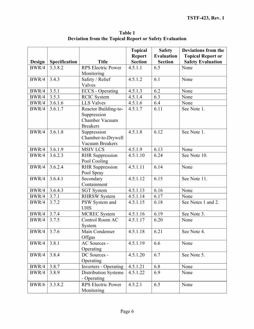
TSTF-423, Rev. 1
Page 6
Table 1 Deviation from the Topical Report or Safety Evaluation
Design Specification Title
Topical Report Section
Safety Evaluation
Section
Deviations from the Topical Report or Safety Evaluation
BWR/4 3.3.8.2 RPS Electric Power Monitoring
4.5.1.1 6.5 None
BWR/4 3.4.3 Safety / Relief Valves
4.5.1.2 6.1 None
BWR/4 3.5.1 ECCS - Operating 4.5.1.3 6.2 None BWR/4 3.5.3 RCIC System 4.5.1.4 6.3 None BWR/4 3.6.1.6 LLS Valves 4.5.1.6 6.4 None BWR/4 3.6.1.7 Reactor Building-to-
Suppression Chamber Vacuum Breakers
4.5.1.7 6.11 See Note 1.
BWR/4 3.6.1.8 Suppression Chamber-to-Drywell Vacuum Breakers
4.5.1.8 6.12 See Note 1.
BWR/4 3.6.1.9 MSIV LCS 4.5.1.9 6.13 None BWR/4 3.6.2.3 RHR Suppression
Pool Cooling 4.5.1.10 6.24 See Note 10.
BWR/4 3.6.2.4 RHR Suppression Pool Spray
4.5.1.11 6.14 None
BWR/4 3.6.4.1 Secondary Containment
4.5.1.12 6.15 See Note 11.
BWR/4 3.6.4.3 SGT System 4.5.1.13 6.16 None BWR/4 3.7.1 RHRSW System 4.5.1.14 6.17 None BWR/4 3.7.2 PSW System and
UHS 4.5.1.15 6.18 See Notes 1 and 2.
BWR/4 3.7.4 MCREC System 4.5.1.16 6.19 See Note 3. BWR/4 3.7.5 Control Room AC
System 4.5.1.17 6.20 None
BWR/4 3.7.6 Main Condenser Offgas
4.5.1.18 6.21 See Note 4.
BWR/4 3.8.1 AC Sources - Operating
4.5.1.19 6.6 None
BWR/4 3.8.4 DC Sources - Operating
4.5.1.20 6.7 See Note 5.
BWR/4 3.8.7 Inverters - Operating 4.5.1.21 6.8 None BWR/4 3.8.9 Distribution Systems
- Operating 4.5.1.22 6.9 None
BWR/6 3.3.8.2 RPS Electric Power Monitoring
4.5.2.1 6.5 None
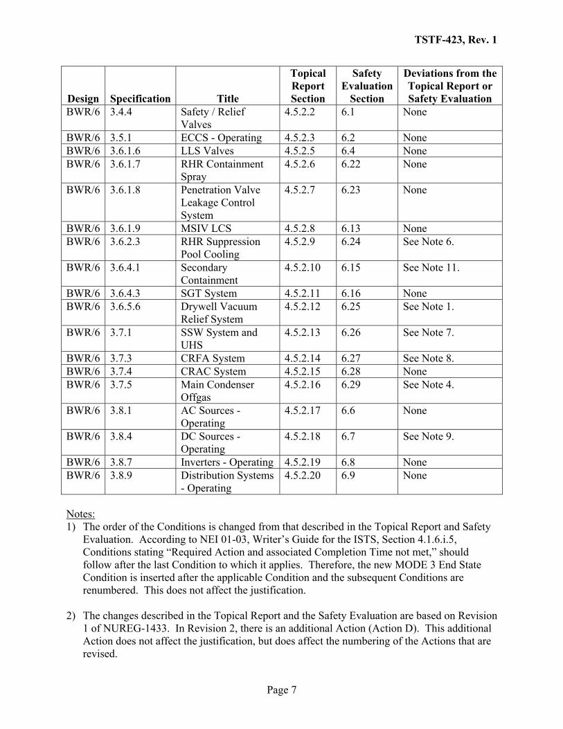
TSTF-423, Rev. 1
Page 7
Design Specification Title
Topical Report Section
Safety Evaluation
Section
Deviations from the Topical Report or Safety Evaluation
BWR/6 3.4.4 Safety / Relief Valves
4.5.2.2 6.1 None
BWR/6 3.5.1 ECCS - Operating 4.5.2.3 6.2 None BWR/6 3.6.1.6 LLS Valves 4.5.2.5 6.4 None BWR/6 3.6.1.7 RHR Containment
Spray 4.5.2.6 6.22 None
BWR/6 3.6.1.8 Penetration Valve Leakage Control System
4.5.2.7 6.23 None
BWR/6 3.6.1.9 MSIV LCS 4.5.2.8 6.13 None BWR/6 3.6.2.3 RHR Suppression
Pool Cooling 4.5.2.9 6.24 See Note 6.
BWR/6 3.6.4.1 Secondary Containment
4.5.2.10 6.15 See Note 11.
BWR/6 3.6.4.3 SGT System 4.5.2.11 6.16 None BWR/6 3.6.5.6 Drywell Vacuum
Relief System 4.5.2.12 6.25 See Note 1.
BWR/6 3.7.1 SSW System and UHS
4.5.2.13 6.26 See Note 7.
BWR/6 3.7.3 CRFA System 4.5.2.14 6.27 See Note 8. BWR/6 3.7.4 CRAC System 4.5.2.15 6.28 None BWR/6 3.7.5 Main Condenser
Offgas 4.5.2.16 6.29 See Note 4.
BWR/6 3.8.1 AC Sources - Operating
4.5.2.17 6.6 None
BWR/6 3.8.4 DC Sources - Operating
4.5.2.18 6.7 See Note 9.
BWR/6 3.8.7 Inverters - Operating 4.5.2.19 6.8 None BWR/6 3.8.9 Distribution Systems
- Operating 4.5.2.20 6.9 None
Notes: 1) The order of the Conditions is changed from that described in the Topical Report and Safety
Evaluation. According to NEI 01-03, Writer’s Guide for the ISTS, Section 4.1.6.i.5, Conditions stating “Required Action and associated Completion Time not met,” should follow after the last Condition to which it applies. Therefore, the new MODE 3 End State Condition is inserted after the applicable Condition and the subsequent Conditions are renumbered. This does not affect the justification.
2) The changes described in the Topical Report and the Safety Evaluation are based on Revision
1 of NUREG-1433. In Revision 2, there is an additional Action (Action D). This additional Action does not affect the justification, but does affect the numbering of the Actions that are revised.
TSTF-423, Rev. 1
Page 8
3) The changes described in the Topical Report and the Safety Evaluation are based on Revision
1 of NUREG-1433. In Revision 2, there is an additional Action (Action B). This Action applies when two MCREC subsystems are inoperable due to an inoperable control room boundary in MODE 1, 2, or 3. Since the Topical Report and the Safety Evaluation justify remaining in MODE 3 when two MCREC subsystems are inoperable for any reason, the MODE 3 end state also is applied to not meeting the Required Action and associated Completion Times of Condition B.
4) No deviations from the Topical Report or the Safety Evaluation. However, deletion of
Required Action B.3.2 necessitates the additional change of renaming Required Action B.3.1 to B.3.
5) The changes described in the Topical Report and the Safety Evaluation are based on Revision
1 of NUREG-1433. In Revision 2, Condition A (one DC electrical power subsystem inoperable) is divided into three Conditions (A - one or two battery chargers in one division inoperable, B - one or two batteries on one division inoperable, and C - one DC electrical power subsystems inoperable for reasons other than Condition A or B). Since the Topical Report and the Safety Evaluation justify remaining in MODE 3 when one DC electrical power subsystem is inoperable for any reason, the MODE 3 end state is applied to not meeting the Required Action and associated Completion Time of Condition A, B, or C.
6) The changes described in the Topical Report and the Safety Evaluation are based on Revision
1 of NUREG-1434. Condition A applies on one inoperable RHR suppression pool cooling subsystem and Condition B applies to two inoperable subsystems. Condition C applies when the Required Actions and associated Completion Times are not met. Therefore, the changes corresponding to the justification given in the Topical and the Safety Evaluation are the addition of a new Condition B which applies when the Required Actions and associated Completion Time of Condition A are not met. Condition B requires being in MODE 3 in 12 hours. Condition C (now D) is modified to only apply to two inoperable RHR suppression pool cooling subsystems (now Condition C). These changes do not affect the justification.
7) The changes described in the Topical Report and the Safety Evaluation are based on Revision
1 of NUREG-1434. In Revision 2, there is a new Condition B which applies when the UHS temperature is water temperature is > 90°F and less than a plant-specific limit. In order to implement the end state change and follow the guidance in NEI 01-03, Condition B is moved to Condition D and Condition C is moved to Condition B. A new Condition C is added which applies when the Required Action and associated Completion Time of Condition A or B are not met. This change does not affect the justification.
8) The changes described in the Topical Report and the Safety Evaluation are based on Revision
1 of NUREG-1434. In Revision 2, there is an additional Action (Action B). This Action applies when two CRFA subsystems are inoperable due to an inoperable control room boundary in MODE 1, 2, or 3. Since the Topical Report and the Safety Evaluation justify remaining in MODE 3 when two CRFA subsystems are inoperable for any reason, the
TSTF-423, Rev. 1
Page 9
MODE 3 end state is applied to not meeting the Required Action and associated Completion Times of Condition B.
9) The changes described in the Topical Report and the Safety Evaluation are based on Revision
1 of NUREG-1434. In Revision 2, Condition A (Division 1 or 2 DC electrical power subsystem inoperable) is divided into three Conditions (A - one or two battery chargers in one division inoperable, B - one or two batteries on one division inoperable, and C - one Division 1 or 2 DC electrical power subsystems inoperable for reasons other than Condition A or B). Since the Topical Report and the Safety Evaluation justify remaining in MODE 3 when one Division 1 or 2 DC electrical power subsystem is inoperable for any reason, the MODE 3 end state is applied to not meeting the Required Action and associated Completion Times of Condition A, B, or C. Modifications are made to apply the MODE 4 end state to a Division 3 DC electrical power subsystem inoperable for any reason. This presentation is consistent with the justification in the Topical Report and the Safety Evaluation.
10) The changes described in the Topical Report and the Safety Evaluation are based on Revision
1 of NUREG-1433. In Revision 2, there is an additional Action (Action B). This additional Action does not affect the justification, but does affect the numbering of the Actions that are revised.
11) The Safety Evaluation finding for these changes referenced the availability of other systems
to maintain defense in depth. These specific references to the availability of other systems are not included in the Traveler. The purpose of the new MODE 3 end state is to allow for performance of maintenance to restore the inoperable system or component. For this situation, 10 CFR 50.65(a)(4) requires that risk impacts of maintenance activity be assessed and managed, and this assessment includes consideration of both the system or component undergoing maintenance and other systems that may be inoperable. Guidance for 10 CFR 50.65(a)(4) risk assessments is provided in Regulatory Guide 1.182, “Assessing and Managing Risk Before Maintenance Activities at Nuclear Power Plants,” which endorses the guidance in Section 11 of NUMARC 93-01, “Industry Guideline for Monitoring the Effectiveness of Maintenance at Nuclear Power Plants.” Since application of 10 CFR 50.65(a)(4) risk assessments include consideration of the system undergoing maintenance and the operability of other systems, it is not necessary to explicitly reference the other systems referenced in the SER.
TSTF-423, Rev. 1
Page 10
Table 2 Implementation of Section 7.0 Stipulations from the Safety Evaluation
Section 7.0 of the Safety Evaluation, “Commitments Needed to Implement the TSs Related to Topical Report NEDC-32988,” states,
Any licensee requesting the TS changes to operate a plant in accordance with this BWROG topical report, must commit to implement the following stipulations in the TS or its associated Bases. The following stipulations assure that the implementation of this topical report will be consistent with staff’s safety evaluation:
Each of the stipulations provided in the Safety Evaluation will be implemented by licensees requesting to adopt the Traveler. However, as discussed below, the Technical Specifications or Bases are not always the appropriate documents to implement the stipulations. The implementation of each of the stipulations is described below.
1. Entry into the shutdown modes approved in this SE shall be for the primary purpose of accomplishing short-duration repairs which necessitated exiting the original operating mode. In response to the staffs questions, the BWROG stated that "The BWRs are most likely to stay in hot shutdown for no more than 2 to 3 days and definitely, not more than a week." The staff expects that the licensees will follow this guidance.
Implementation
The Bases for each modified Required Action which allows remaining in MODE 3 is modified to include the following statement, “Remaining in the Applicability of the LCO is acceptable because the plant risk in MODE 3 is similar to or lower than the risk in MODE 4 and because the time spent in MODE 3 to perform the necessary repairs to restore the system to OPERABLE status will be short.” Regarding the specific time limits, a BWR in MODE 3 only generates sufficient decay heat to remain in MODE 3 for 2 to 3 days, and for not more than a week. Therefore, this is not an administrative limitation, but a physical limitation. As a result, there is no need for a licensee to incorporate these specific times in the Technical Specifications or Bases.
2. Appropriate plant procedures and administrative controls will be used when the plant is
operated in the proposed end states.
Implementation Licensees will implement appropriate plant procedures and administrative controls to be used when the plant is operated in the proposed end states as required by Technical Specification 5.4, “Procedures,” and 10 CFR 50, Appendix B. Appropriate plant procedures and administrative controls must be used when the plant is operated in any plant operating MODE. The MODE 3 end states are not unique in this regard. Therefore, this stipulation is not appropriate for inclusion in the Technical Specifications or Bases as it is does not provide guidance to the operator that is unique to the conditions to be entered.
TSTF-423, Rev. 1
Page 11
3. Entry into and use of the proposed end states shall be in accordance with the requirements of 10 CFR 50.65(b)(4). The licensee should do a risk assessment with respect to performance of the key shutdown safety functions, as described in Section 4 of this SE.
(There is no 10 CFR 50.65(b)(4); it is assumed that the reference was to 10 CFR 50.65(a)(4).) Implementation Use of the new MODE 3 end states will be accompanied by the performance of maintenance to restore the inoperable system or component. When performing maintenance, licensees are required to perform a risk assessment by 10 CFR 50.65(a)(4). This risk assessment is in accordance with the plant procedures in place to implement 10 CFR 50.65(a)(4) and envelopes the situation where entering a MODE or other specified condition in the applicability is contemplated with plant equipment inoperable. Those plant procedures will follow the guidance in NUMARC 93-01, “Assessment of Resulting from Performance of Maintenance Activities,” Section 11, as revised in February 2000 and as endorsed by NRC Regulatory Guide 1.182, “Assessing and Managing Risk Before Maintenance Activities at Nuclear Power Plants.” The risk evaluations performed in accordance with these documents consider the key shutdown safety functions. Therefore, implementation of these end state changes imposes no new requirements with regard to implementation of 10 CFR 50.65(a)(4). As a result, this stipulation is not appropriate for inclusion in the Technical Specifications or Bases as it is contrary to the content and format of the Improved Standard Technical Specifications to repeat regulatory requirements in the Technical Specifications.
4. The purpose of the BWROG request is to allow corrective maintenance in a safe
operating mode after an CT has been exceeded and minimize the corrective action time so that the plant can be restored to power operation. Ordinarily the failures result in a degraded plant condition. Consequently, with respect to additional licensee outage activities that could affect the safe conduct of operations and that are not directly required for correction of the failure or failures that caused the CT to be exceeded, a licensee must make two commitments:
a. The licensee will perform a safety assessment in accordance with the maintenance rule prior to undertaking such additional activities.
b. If conditions change so that the safety assessment is no longer valid, the licensee will suspend all such additional activities via a process consistent with safety until the assessment has been revalidated. The staff expects the licensee to make a contingency plan to address this situation. The contingency plan may require such actions as (1) suspending the activity until conditions are again appropriate, (2) terminating the activity and starting over when conditions are again appropriate, and (3) continuing the activity if safety is best ensured by completing the activity. The staff recognizes that such decisions may have to be made on the basis of engineering judgment should an unforeseen situation arise.
TSTF-423, Rev. 1
Page 12
Implementation Use of the new MODE 3 end states will be accompanied by the performance of maintenance to restore the inoperable system or component. When performing maintenance licensees are required to perform a risk assessment by 10 CFR 50.65(a)(4). This risk assessment must consider all maintenance being performed, regardless of whether the maintenance is related to restoring the inoperable equipment which lead to the use of the new MODE 3 end state. Therefore, the inclusion of stipulation 4.a in the Technical Specifications or Bases is not needed as it is unnecessary for a licensee to commit to follow the requirements in 10 CFR 50.65(a)(4). The requirements of 10 CFR 50 are imposed by regulation. If plant conditions change during performance of maintenance, 10 CFR 50.65(a)(4) requires the new condition to evaluated, and if necessary, risk management actions to be taken. The actions may include stopping the maintenance activity, taking other risk management actions, or completing the activity. These actions are implemented in plant procedures. Therefore, inclusion of stipulation 4.b in the Technical Specifications or Bases is not needed as it is unnecessary for a licensee to commit to having a contingency plan to follow the requirements in 10 CFR 50.65(a)(4). The requirements of 10 CFR 50 are already imposed by regulation. In addition, it is contrary to the content and format of the Improved Standard Technical Specifications to repeat regulatory requirements in the Technical Specifications. 5. The requested end state changes do not prohibit licensees from entering cold shutdown if
they wish to do so for operational reasons or maintenance requirements. In such cases, the specific requirements associated with the requested end state changes do not apply.
Implementation The Bases for each modified Required Action which allows remaining in MODE 3 is modified to include the following statement, “Voluntary entry into MODE 4 may be made as it is also an acceptable low-risk state.” As stated above, the specific requirements associated with the MODE 3 end states are not unique to implementation of this change. Therefore, it not necessary to implement the qualification that these requirements do not apply if cold shutdown is entered. Once MODE 4 is entered, the subject Technical Specifications do not apply. Therefore, any requirements associated with the modified Required Actions are not applicable. As a result, it is not necessary to implement this stipulation in the Technical Specifications or Bases.

RPS Electric Power Monitoring 3.3.8.2
BWR/4 STS 3.3.8.2-1 Rev. 3.0, 03/31/04
3.3 INSTRUMENTATION 3.3.8.2 Reactor Protection System (RPS) Electric Power Monitoring LCO 3.3.8.2 Two RPS electric power monitoring assemblies shall be OPERABLE for
each inservice RPS motor generator set or alternate power supply. APPLICABILITY: MODES 1, 2, and 3, MODES 4 and 5 [with any control rod withdrawn from a core cell
containing one or more fuel assemblies]. ACTIONS
CONDITION
REQUIRED ACTION
COMPLETION TIME
A. One or both inservice
power supplies with one electric power monitoring assembly inoperable.
A.1 Remove associated
inservice power supply(s) from service.
72 hours
B. One or both inservice
power supplies with both electric power monitoring assemblies inoperable.
B.1 Remove associated
inservice power supply(s) from service.
1 hour
C. Required Action and
associated Completion Time of Condition A or B not met in MODE 1, 2, or 3.
C.1 -------------- NOTE ------------- LCO 3.0.4.a is not
applicable when entering MODE 3.
------------------------------------- Be in MODE 3. AND C.2 Be in MODE 4.
12 hours 36 hours
D. Required Action and
associated Completion Time of Condition A or B not met in MODE 4 or 5
D.1 Initiate action to fully insert
all insertable control rods in core cells containing one or more fuel assemblies.
Immediately
TSTF-423, Rev. 1
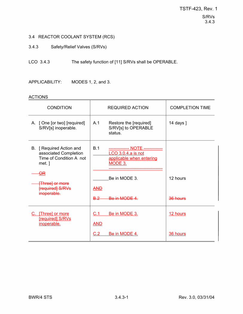
S/RVs 3.4.3
BWR/4 STS 3.4.3-1 Rev. 3.0, 03/31/04
3.4 REACTOR COOLANT SYSTEM (RCS) 3.4.3 Safety/Relief Valves (S/RVs) LCO 3.4.3 The safety function of [11] S/RVs shall be OPERABLE. APPLICABILITY: MODES 1, 2, and 3. ACTIONS
CONDITION
REQUIRED ACTION
COMPLETION TIME
A. [ One [or two] [required]
S/RV[s] inoperable.
A.1 Restore the [required]
S/RV[s] to OPERABLE status.
14 days ]
B. [ Required Action and
associated Completion Time of Condition A not met. ]
OR [Three] or more
[required] S/RVs inoperable.
B.1 -------------- NOTE ------------- LCO 3.0.4.a is not
applicable when entering MODE 3.
------------------------------------- Be in MODE 3. AND B.2 Be in MODE 4.
12 hours 36 hours
C. [Three] or more
[required] S/RVs inoperable.
C.1 Be in MODE 3. AND C.2 Be in MODE 4.
12 hours 36 hours
TSTF-423, Rev. 1
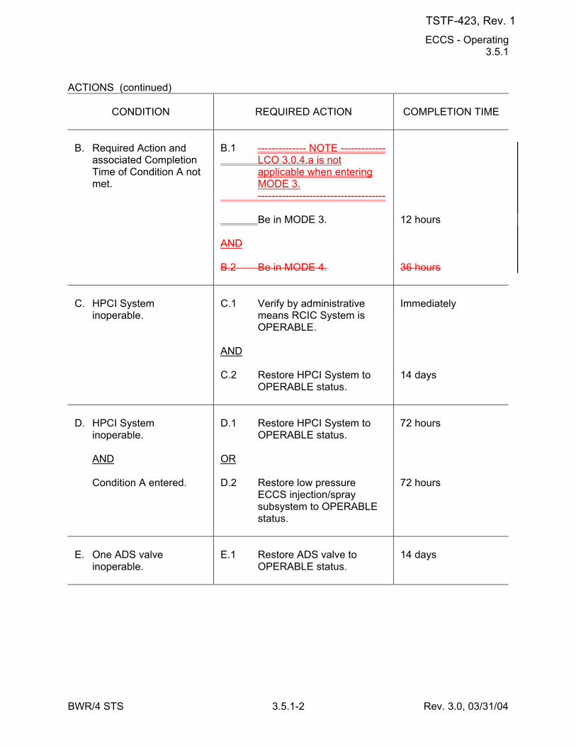
ECCS - Operating 3.5.1
BWR/4 STS 3.5.1-2 Rev. 3.0, 03/31/04
ACTIONS (continued)
CONDITION
REQUIRED ACTION
COMPLETION TIME
B. Required Action and
associated Completion Time of Condition A not met.
B.1 -------------- NOTE ------------- LCO 3.0.4.a is not
applicable when entering MODE 3.
------------------------------------- Be in MODE 3. AND B.2 Be in MODE 4.
12 hours 36 hours
C. HPCI System
inoperable.
C.1 Verify by administrative
means RCIC System is OPERABLE.
AND C.2 Restore HPCI System to
OPERABLE status.
Immediately 14 days
D. HPCI System
inoperable. AND Condition A entered.
D.1 Restore HPCI System to
OPERABLE status. OR D.2 Restore low pressure
ECCS injection/spray subsystem to OPERABLE status.
72 hours 72 hours
E. One ADS valve
inoperable.
E.1 Restore ADS valve to
OPERABLE status.
14 days
TSTF-423, Rev. 1
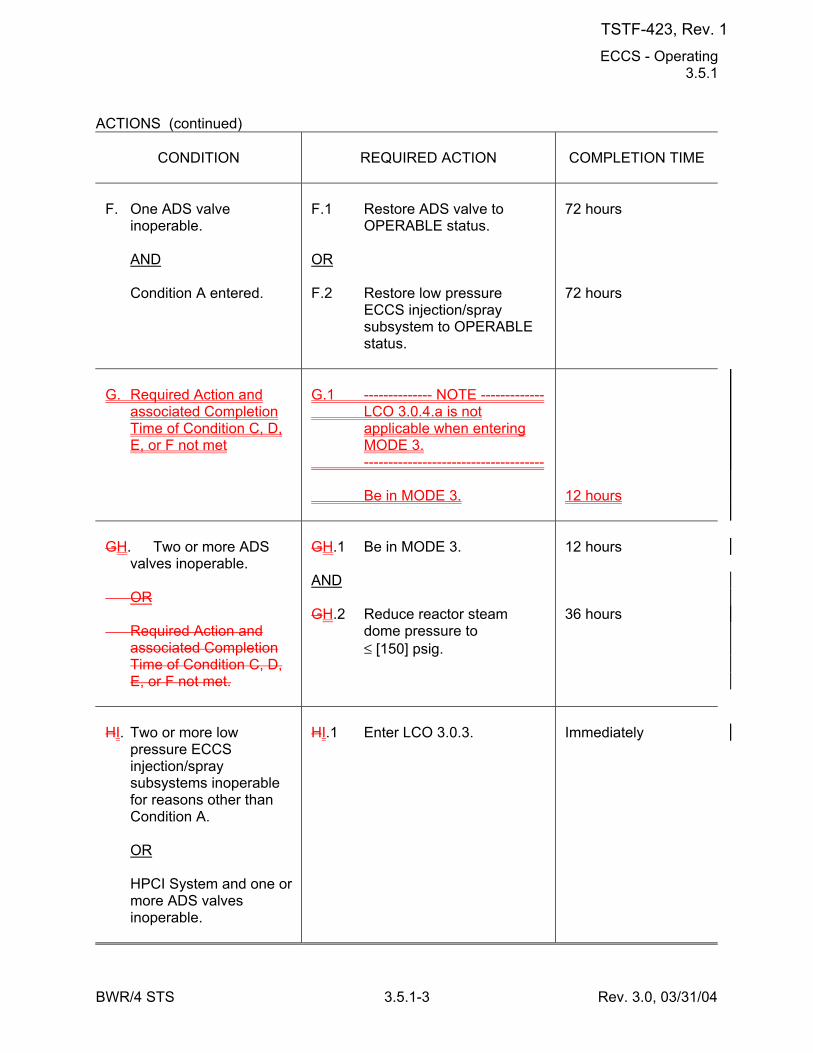
ECCS - Operating 3.5.1
BWR/4 STS 3.5.1-3 Rev. 3.0, 03/31/04
ACTIONS (continued)
CONDITION
REQUIRED ACTION
COMPLETION TIME
F. One ADS valve
inoperable. AND Condition A entered.
F.1 Restore ADS valve to
OPERABLE status. OR F.2 Restore low pressure
ECCS injection/spray subsystem to OPERABLE status.
72 hours 72 hours
G. Required Action and
associated Completion Time of Condition C, D, E, or F not met
G.1 -------------- NOTE ------------- LCO 3.0.4.a is not
applicable when entering MODE 3.
------------------------------------- Be in MODE 3.
12 hours
GH. Two or more ADS
valves inoperable. OR Required Action and
associated Completion Time of Condition C, D, E, or F not met.
GH.1 Be in MODE 3. AND GH.2 Reduce reactor steam
dome pressure to ≤ [150] psig.
12 hours 36 hours
HI. Two or more low
pressure ECCS injection/spray subsystems inoperable for reasons other than Condition A.
OR HPCI System and one or
more ADS valves inoperable.
HI.1 Enter LCO 3.0.3.
Immediately
TSTF-423, Rev. 1
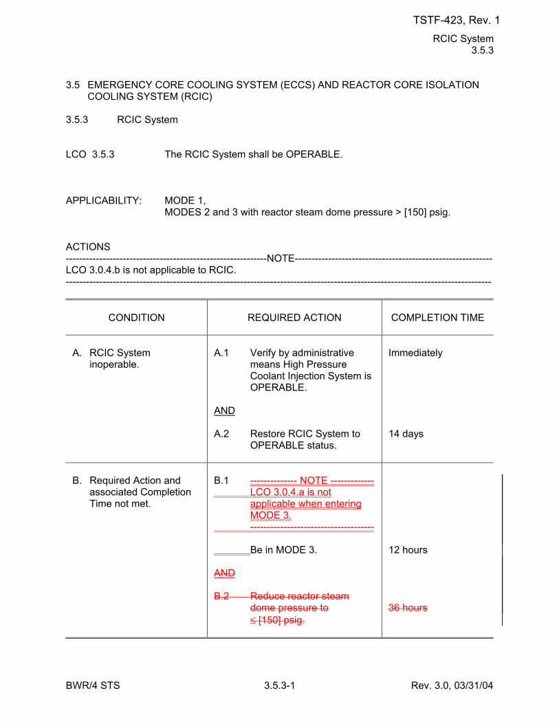
RCIC System 3.5.3
BWR/4 STS 3.5.3-1 Rev. 3.0, 03/31/04
3.5 EMERGENCY CORE COOLING SYSTEM (ECCS) AND REACTOR CORE ISOLATION COOLING SYSTEM (RCIC)
3.5.3 RCIC System LCO 3.5.3 The RCIC System shall be OPERABLE. APPLICABILITY: MODE 1, MODES 2 and 3 with reactor steam dome pressure > [150] psig. ACTIONS ------------------------------------------------------------NOTE----------------------------------------------------------- LCO 3.0.4.b is not applicable to RCIC. -------------------------------------------------------------------------------------------------------------------------------
CONDITION
REQUIRED ACTION
COMPLETION TIME
A. RCIC System
inoperable.
A.1 Verify by administrative
means High Pressure Coolant Injection System is OPERABLE.
AND A.2 Restore RCIC System to
OPERABLE status.
Immediately 14 days
B. Required Action and
associated Completion Time not met.
B.1 -------------- NOTE ------------- LCO 3.0.4.a is not
applicable when entering MODE 3.
------------------------------------- Be in MODE 3. AND B.2 Reduce reactor steam
dome pressure to ≤ [150] psig.
12 hours 36 hours
TSTF-423, Rev. 1
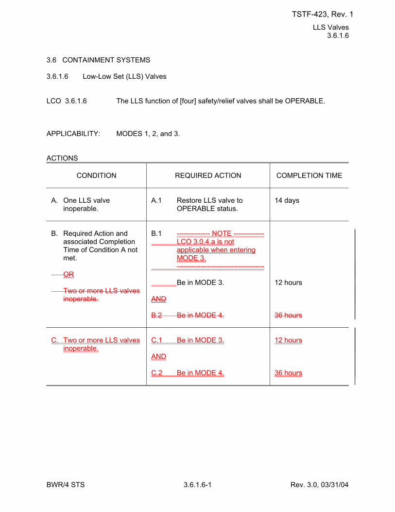
LLS Valves 3.6.1.6
BWR/4 STS 3.6.1.6-1 Rev. 3.0, 03/31/04
3.6 CONTAINMENT SYSTEMS 3.6.1.6 Low-Low Set (LLS) Valves LCO 3.6.1.6 The LLS function of [four] safety/relief valves shall be OPERABLE. APPLICABILITY: MODES 1, 2, and 3. ACTIONS
CONDITION
REQUIRED ACTION
COMPLETION TIME
A. One LLS valve
inoperable.
A.1 Restore LLS valve to
OPERABLE status.
14 days
B. Required Action and
associated Completion Time of Condition A not met.
OR Two or more LLS valves
inoperable.
B.1 -------------- NOTE ------------- LCO 3.0.4.a is not
applicable when entering MODE 3.
------------------------------------- Be in MODE 3. AND B.2 Be in MODE 4.
12 hours 36 hours
C. Two or more LLS valves
inoperable.
C.1 Be in MODE 3. AND C.2 Be in MODE 4.
12 hours 36 hours
TSTF-423, Rev. 1
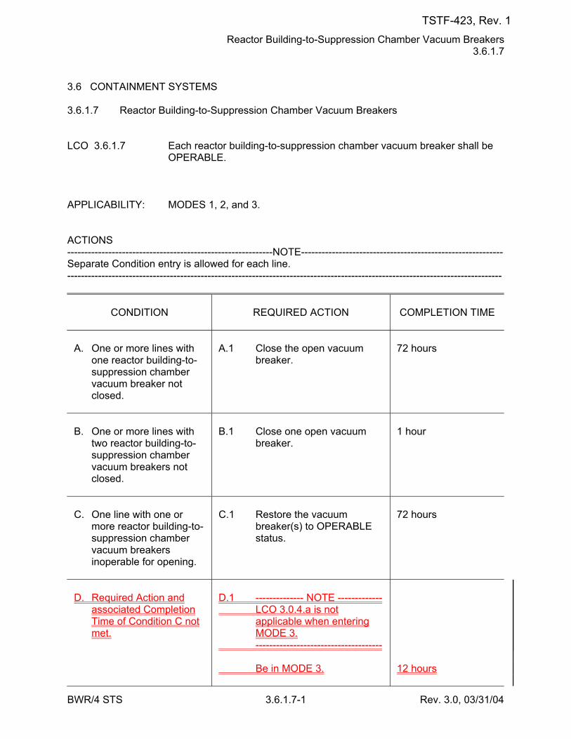
Reactor Building-to-Suppression Chamber Vacuum Breakers 3.6.1.7
BWR/4 STS 3.6.1.7-1 Rev. 3.0, 03/31/04
3.6 CONTAINMENT SYSTEMS 3.6.1.7 Reactor Building-to-Suppression Chamber Vacuum Breakers LCO 3.6.1.7 Each reactor building-to-suppression chamber vacuum breaker shall be
OPERABLE. APPLICABILITY: MODES 1, 2, and 3. ACTIONS ------------------------------------------------------------NOTE----------------------------------------------------------- Separate Condition entry is allowed for each line. -------------------------------------------------------------------------------------------------------------------------------
CONDITION
REQUIRED ACTION
COMPLETION TIME
A. One or more lines with
one reactor building-to-suppression chamber vacuum breaker not closed.
A.1 Close the open vacuum
breaker.
72 hours
B. One or more lines with
two reactor building-to-suppression chamber vacuum breakers not closed.
B.1 Close one open vacuum
breaker.
1 hour
C. One line with one or
more reactor building-to-suppression chamber vacuum breakers inoperable for opening.
C.1 Restore the vacuum
breaker(s) to OPERABLE status.
72 hours
D. Required Action and
associated Completion Time of Condition C not met.
D.1 -------------- NOTE ------------- LCO 3.0.4.a is not
applicable when entering MODE 3.
------------------------------------- Be in MODE 3.
12 hours
TSTF-423, Rev. 1
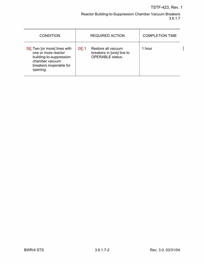
Reactor Building-to-Suppression Chamber Vacuum Breakers 3.6.1.7
BWR/4 STS 3.6.1.7-2 Rev. 3.0, 03/31/04
CONDITION
REQUIRED ACTION
COMPLETION TIME
DE. Two [or more] lines with
one or more reactor building-to-suppression chamber vacuum breakers inoperable for opening.
DE.1 Restore all vacuum
breakers in [one] line to OPERABLE status.
1 hour
TSTF-423, Rev. 1
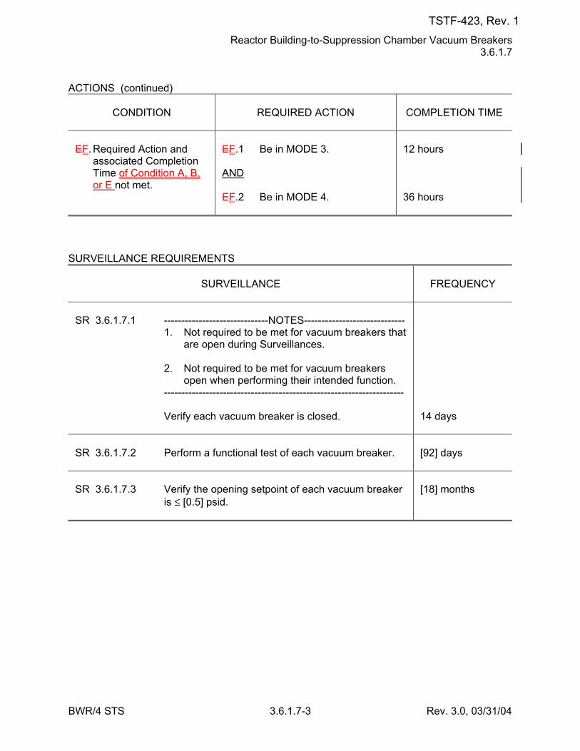
Reactor Building-to-Suppression Chamber Vacuum Breakers 3.6.1.7
BWR/4 STS 3.6.1.7-3 Rev. 3.0, 03/31/04
ACTIONS (continued)
CONDITION
REQUIRED ACTION
COMPLETION TIME
EF. Required Action and
associated Completion Time of Condition A, B, or E not met.
EF.1 Be in MODE 3. AND EF.2 Be in MODE 4.
12 hours 36 hours
SURVEILLANCE REQUIREMENTS
SURVEILLANCE
FREQUENCY
SR 3.6.1.7.1 ------------------------------NOTES----------------------------- 1. Not required to be met for vacuum breakers that
are open during Surveillances. 2. Not required to be met for vacuum breakers
open when performing their intended function. --------------------------------------------------------------------- Verify each vacuum breaker is closed.
14 days
SR 3.6.1.7.2 Perform a functional test of each vacuum breaker.
[92] days
SR 3.6.1.7.3 Verify the opening setpoint of each vacuum breaker
is ≤ [0.5] psid.
[18] months
TSTF-423, Rev. 1
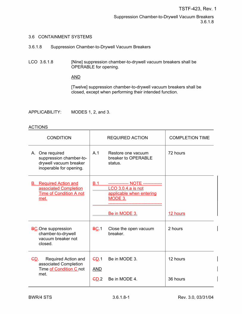
Suppression Chamber-to-Drywell Vacuum Breakers 3.6.1.8
BWR/4 STS 3.6.1.8-1 Rev. 3.0, 03/31/04
3.6 CONTAINMENT SYSTEMS 3.6.1.8 Suppression Chamber-to-Drywell Vacuum Breakers LCO 3.6.1.8 [Nine] suppression chamber-to-drywell vacuum breakers shall be
OPERABLE for opening. AND [Twelve] suppression chamber-to-drywell vacuum breakers shall be
closed, except when performing their intended function. APPLICABILITY: MODES 1, 2, and 3. ACTIONS
CONDITION
REQUIRED ACTION
COMPLETION TIME
A. One required
suppression chamber-to-drywell vacuum breaker inoperable for opening.
A.1 Restore one vacuum
breaker to OPERABLE status.
72 hours
B. Required Action and
associated Completion Time of Condition A not met.
B.1 -------------- NOTE ------------- LCO 3.0.4.a is not
applicable when entering MODE 3.
------------------------------------- Be in MODE 3.
12 hours
BC. One suppression
chamber-to-drywell vacuum breaker not closed.
BC.1 Close the open vacuum
breaker.
2 hours
CD. Required Action and
associated Completion Time of Condition C not met.
CD.1 Be in MODE 3. AND CD.2 Be in MODE 4.
12 hours 36 hours
TSTF-423, Rev. 1

MSIV LCS 3.6.1.9
BWR/4 STS 3.6.1.9-1 Rev. 3.0, 03/31/04
3.6 CONTAINMENT SYSTEMS 3.6.1.9 Main Steam Isolation Valve (MSIV) Leakage Control System (LCS) LCO 3.6.1.9 Two MSIV LCS subsystems shall be OPERABLE. APPLICABILITY: MODES 1, 2, and 3. ACTIONS
CONDITION
REQUIRED ACTION
COMPLETION TIME
A. One MSIV LCS
subsystem inoperable.
A.1 Restore MSIV LCS
subsystem to OPERABLE status.
30 days
B. Two MSIV LCS
subsystems inoperable.
B.1 Restore one MSIV LCS
subsystem to OPERABLE status.
7 days
C. Required Action and
associated Completion Time not met.
C.1 -------------- NOTE ------------- LCO 3.0.4.a is not
applicable when entering MODE 3.
------------------------------------- Be in MODE 3. AND C.2 Be in MODE 4.
12 hours 36 hours
SURVEILLANCE REQUIREMENTS
SURVEILLANCE
FREQUENCY
SR 3.6.1.9.1 Operate each MSIV LCS blower ≥ [15] minutes.
31 days
SR 3.6.1.9.2 Verify electrical continuity of each inboard MSIV
31 days
TSTF-423, Rev. 1
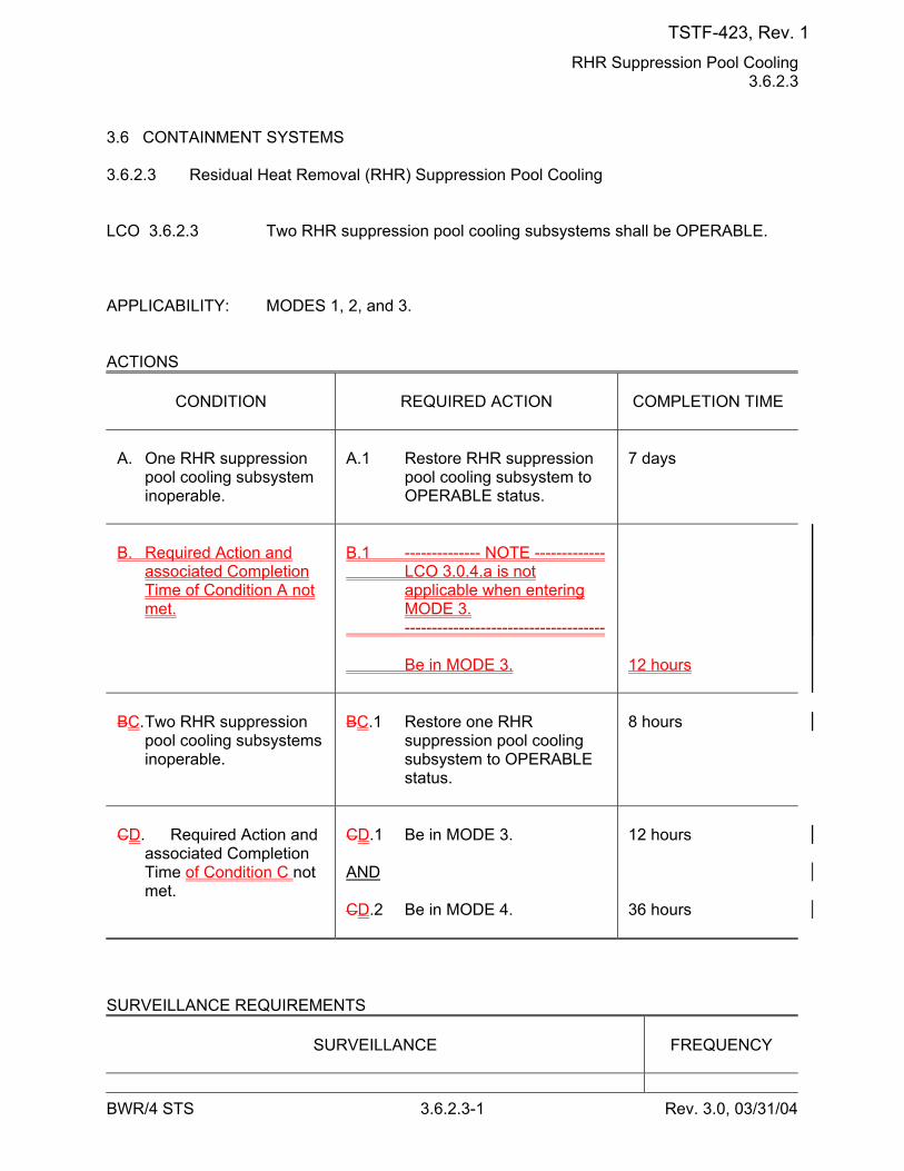
RHR Suppression Pool Cooling 3.6.2.3
BWR/4 STS 3.6.2.3-1 Rev. 3.0, 03/31/04
3.6 CONTAINMENT SYSTEMS 3.6.2.3 Residual Heat Removal (RHR) Suppression Pool Cooling LCO 3.6.2.3 Two RHR suppression pool cooling subsystems shall be OPERABLE. APPLICABILITY: MODES 1, 2, and 3. ACTIONS
CONDITION
REQUIRED ACTION
COMPLETION TIME
A. One RHR suppression
pool cooling subsystem inoperable.
A.1 Restore RHR suppression
pool cooling subsystem to OPERABLE status.
7 days
B. Required Action and
associated Completion Time of Condition A not met.
B.1 -------------- NOTE ------------- LCO 3.0.4.a is not
applicable when entering MODE 3.
------------------------------------- Be in MODE 3.
12 hours
BC. Two RHR suppression
pool cooling subsystems inoperable.
BC.1 Restore one RHR
suppression pool cooling subsystem to OPERABLE status.
8 hours
CD. Required Action and
associated Completion Time of Condition C not met.
CD.1 Be in MODE 3. AND CD.2 Be in MODE 4.
12 hours 36 hours
SURVEILLANCE REQUIREMENTS
SURVEILLANCE
FREQUENCY
TSTF-423, Rev. 1
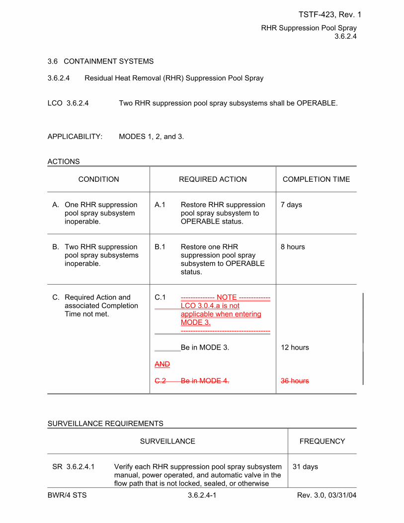
RHR Suppression Pool Spray 3.6.2.4
BWR/4 STS 3.6.2.4-1 Rev. 3.0, 03/31/04
3.6 CONTAINMENT SYSTEMS 3.6.2.4 Residual Heat Removal (RHR) Suppression Pool Spray LCO 3.6.2.4 Two RHR suppression pool spray subsystems shall be OPERABLE. APPLICABILITY: MODES 1, 2, and 3. ACTIONS
CONDITION
REQUIRED ACTION
COMPLETION TIME
A. One RHR suppression
pool spray subsystem inoperable.
A.1 Restore RHR suppression
pool spray subsystem to OPERABLE status.
7 days
B. Two RHR suppression
pool spray subsystems inoperable.
B.1 Restore one RHR
suppression pool spray subsystem to OPERABLE status.
8 hours
C. Required Action and
associated Completion Time not met.
C.1 -------------- NOTE ------------- LCO 3.0.4.a is not
applicable when entering MODE 3.
------------------------------------- Be in MODE 3. AND C.2 Be in MODE 4.
12 hours 36 hours
SURVEILLANCE REQUIREMENTS
SURVEILLANCE
FREQUENCY
SR 3.6.2.4.1 Verify each RHR suppression pool spray subsystem
manual, power operated, and automatic valve in the flow path that is not locked, sealed, or otherwise
31 days
TSTF-423, Rev. 1
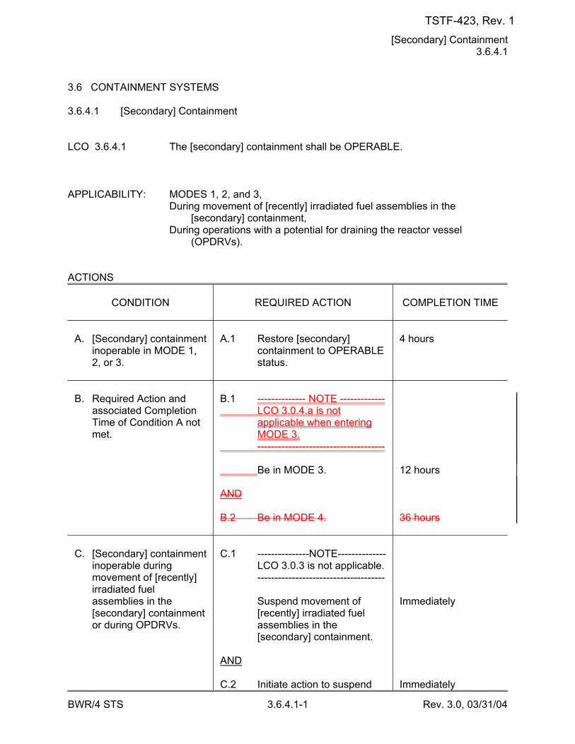
[Secondary] Containment 3.6.4.1
BWR/4 STS 3.6.4.1-1 Rev. 3.0, 03/31/04
3.6 CONTAINMENT SYSTEMS 3.6.4.1 [Secondary] Containment LCO 3.6.4.1 The [secondary] containment shall be OPERABLE. APPLICABILITY: MODES 1, 2, and 3, During movement of [recently] irradiated fuel assemblies in the
[secondary] containment, During operations with a potential for draining the reactor vessel
(OPDRVs). ACTIONS
CONDITION
REQUIRED ACTION
COMPLETION TIME
A. [Secondary] containment
inoperable in MODE 1, 2, or 3.
A.1 Restore [secondary]
containment to OPERABLE status.
4 hours
B. Required Action and
associated Completion Time of Condition A not met.
B.1 -------------- NOTE ------------- LCO 3.0.4.a is not
applicable when entering MODE 3.
------------------------------------- Be in MODE 3. AND B.2 Be in MODE 4.
12 hours 36 hours
C. [Secondary] containment
inoperable during movement of [recently] irradiated fuel assemblies in the [secondary] containment or during OPDRVs.
C.1 ---------------NOTE-------------- LCO 3.0.3 is not applicable. ------------------------------------- Suspend movement of
[recently] irradiated fuel assemblies in the [secondary] containment.
AND C.2 Initiate action to suspend
Immediately Immediately
TSTF-423, Rev. 1
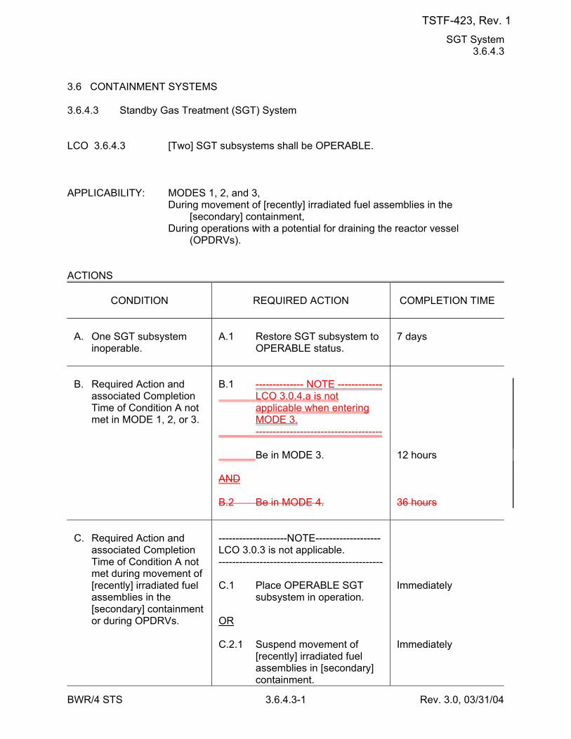
SGT System 3.6.4.3
BWR/4 STS 3.6.4.3-1 Rev. 3.0, 03/31/04
3.6 CONTAINMENT SYSTEMS 3.6.4.3 Standby Gas Treatment (SGT) System LCO 3.6.4.3 [Two] SGT subsystems shall be OPERABLE. APPLICABILITY: MODES 1, 2, and 3, During movement of [recently] irradiated fuel assemblies in the
[secondary] containment, During operations with a potential for draining the reactor vessel
(OPDRVs). ACTIONS
CONDITION
REQUIRED ACTION
COMPLETION TIME
A. One SGT subsystem
inoperable.
A.1 Restore SGT subsystem to
OPERABLE status.
7 days
B. Required Action and
associated Completion Time of Condition A not met in MODE 1, 2, or 3.
B.1 -------------- NOTE ------------- LCO 3.0.4.a is not
applicable when entering MODE 3.
------------------------------------- Be in MODE 3. AND B.2 Be in MODE 4.
12 hours 36 hours
C. Required Action and
associated Completion Time of Condition A not met during movement of [recently] irradiated fuel assemblies in the [secondary] containment or during OPDRVs.
--------------------NOTE------------------- LCO 3.0.3 is not applicable. ------------------------------------------------ C.1 Place OPERABLE SGT
subsystem in operation. OR C.2.1 Suspend movement of
[recently] irradiated fuel assemblies in [secondary] containment.
Immediately Immediately
TSTF-423, Rev. 1
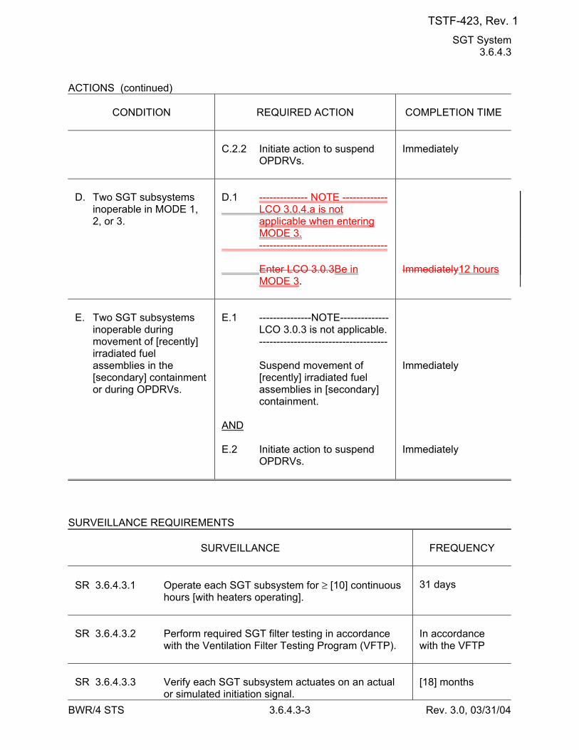
SGT System 3.6.4.3
BWR/4 STS 3.6.4.3-3 Rev. 3.0, 03/31/04
ACTIONS (continued)
CONDITION
REQUIRED ACTION
COMPLETION TIME
C.2.2 Initiate action to suspend
OPDRVs.
Immediately
D. Two SGT subsystems
inoperable in MODE 1, 2, or 3.
D.1 -------------- NOTE ------------- LCO 3.0.4.a is not
applicable when entering MODE 3.
------------------------------------- Enter LCO 3.0.3Be in
MODE 3.
Immediately12 hours
E. Two SGT subsystems
inoperable during movement of [recently] irradiated fuel assemblies in the [secondary] containment or during OPDRVs.
E.1 ---------------NOTE-------------- LCO 3.0.3 is not applicable. ------------------------------------- Suspend movement of
[recently] irradiated fuel assemblies in [secondary] containment.
AND E.2 Initiate action to suspend
OPDRVs.
Immediately Immediately
SURVEILLANCE REQUIREMENTS
SURVEILLANCE
FREQUENCY
SR 3.6.4.3.1 Operate each SGT subsystem for ≥ [10] continuous
hours [with heaters operating].
31 days
SR 3.6.4.3.2 Perform required SGT filter testing in accordance
with the Ventilation Filter Testing Program (VFTP).
In accordance with the VFTP
SR 3.6.4.3.3 Verify each SGT subsystem actuates on an actual
or simulated initiation signal.
[18] months
TSTF-423, Rev. 1
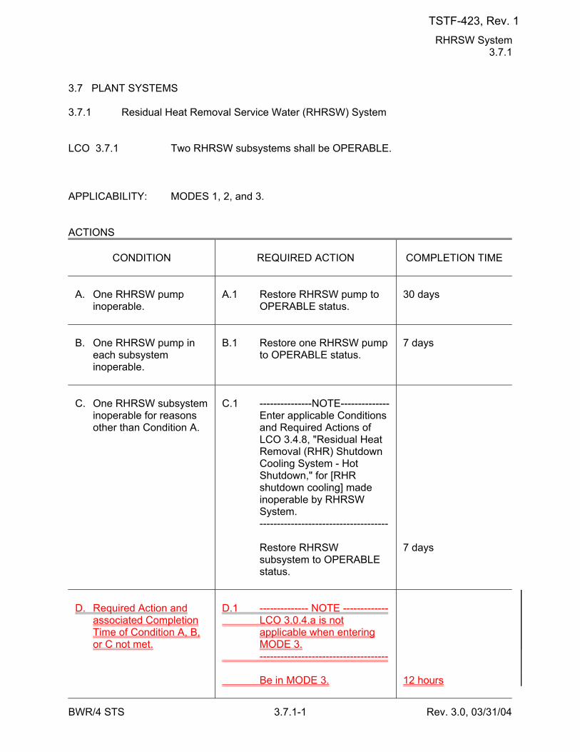
RHRSW System 3.7.1
BWR/4 STS 3.7.1-1 Rev. 3.0, 03/31/04
3.7 PLANT SYSTEMS 3.7.1 Residual Heat Removal Service Water (RHRSW) System LCO 3.7.1 Two RHRSW subsystems shall be OPERABLE. APPLICABILITY: MODES 1, 2, and 3. ACTIONS
CONDITION
REQUIRED ACTION
COMPLETION TIME
A. One RHRSW pump
inoperable.
A.1 Restore RHRSW pump to
OPERABLE status.
30 days
B. One RHRSW pump in
each subsystem inoperable.
B.1 Restore one RHRSW pump
to OPERABLE status.
7 days
C. One RHRSW subsystem
inoperable for reasons other than Condition A.
C.1 ---------------NOTE-------------- Enter applicable Conditions
and Required Actions of LCO 3.4.8, "Residual Heat Removal (RHR) Shutdown Cooling System - Hot Shutdown," for [RHR shutdown cooling] made inoperable by RHRSW System.
------------------------------------- Restore RHRSW
subsystem to OPERABLE status.
7 days
D. Required Action and
associated Completion Time of Condition A, B, or C not met.
D.1 -------------- NOTE ------------- LCO 3.0.4.a is not
applicable when entering MODE 3.
------------------------------------- Be in MODE 3.
12 hours
TSTF-423, Rev. 1
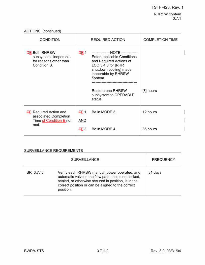
RHRSW System 3.7.1
BWR/4 STS 3.7.1-2 Rev. 3.0, 03/31/04
ACTIONS (continued)
CONDITION
REQUIRED ACTION
COMPLETION TIME
DE. Both RHRSW
subsystems inoperable for reasons other than Condition B.
DE.1 ---------------NOTE-------------- Enter applicable Conditions
and Required Actions of LCO 3.4.8 for [RHR shutdown cooling] made inoperable by RHRSW System.
------------------------------------- Restore one RHRSW
subsystem to OPERABLE status.
[8] hours
EF. Required Action and
associated Completion Time of Condition E not met.
EF.1 Be in MODE 3. AND EF.2 Be in MODE 4.
12 hours 36 hours
SURVEILLANCE REQUIREMENTS
SURVEILLANCE
FREQUENCY
SR 3.7.1.1 Verify each RHRSW manual, power operated, and
automatic valve in the flow path, that is not locked, sealed, or otherwise secured in position, is in the correct position or can be aligned to the correct position.
31 days
TSTF-423, Rev. 1
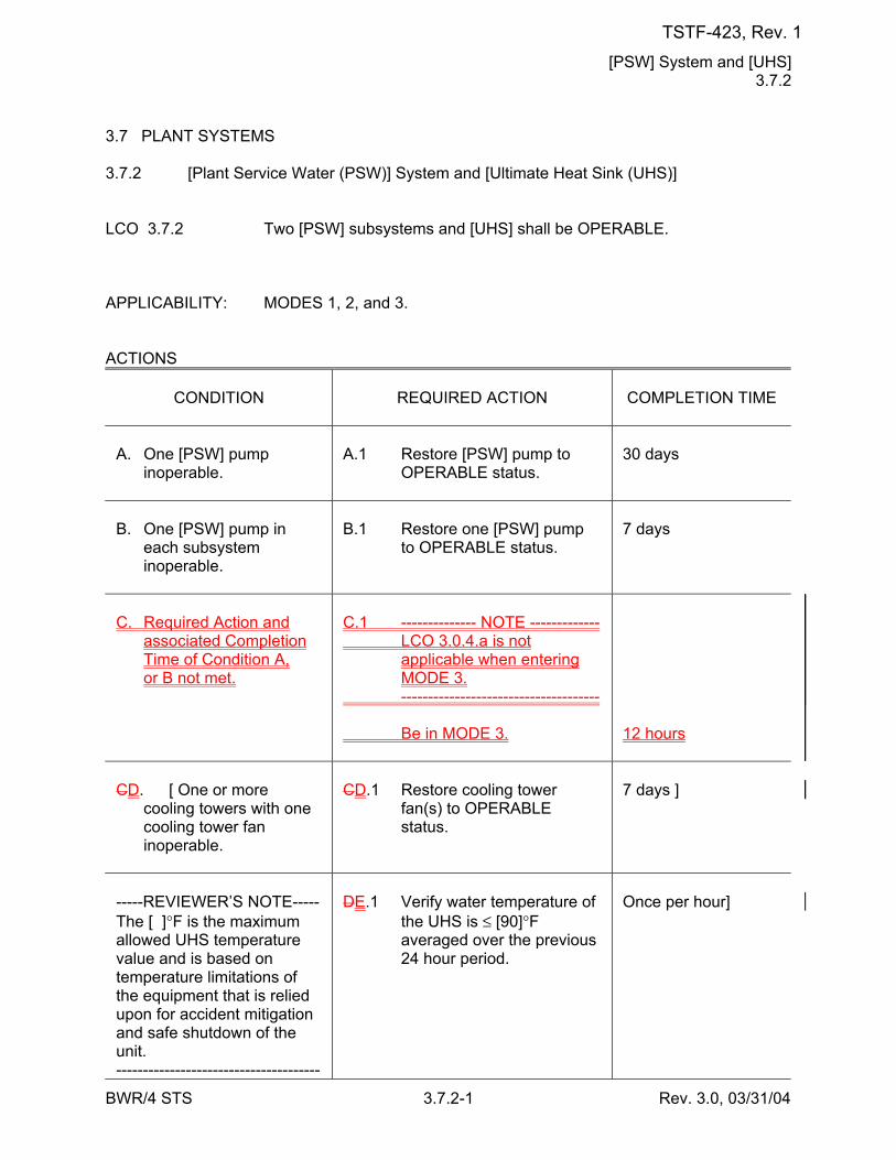
[PSW] System and [UHS] 3.7.2
BWR/4 STS 3.7.2-1 Rev. 3.0, 03/31/04
3.7 PLANT SYSTEMS 3.7.2 [Plant Service Water (PSW)] System and [Ultimate Heat Sink (UHS)] LCO 3.7.2 Two [PSW] subsystems and [UHS] shall be OPERABLE. APPLICABILITY: MODES 1, 2, and 3. ACTIONS
CONDITION
REQUIRED ACTION
COMPLETION TIME
A. One [PSW] pump
inoperable.
A.1 Restore [PSW] pump to
OPERABLE status.
30 days
B. One [PSW] pump in
each subsystem inoperable.
B.1 Restore one [PSW] pump
to OPERABLE status.
7 days
C. Required Action and
associated Completion Time of Condition A, or B not met.
C.1 -------------- NOTE ------------- LCO 3.0.4.a is not
applicable when entering MODE 3.
------------------------------------- Be in MODE 3.
12 hours
CD. [ One or more
cooling towers with one cooling tower fan inoperable.
CD.1 Restore cooling tower
fan(s) to OPERABLE status.
7 days ]
-----REVIEWER’S NOTE----- The [ ]°F is the maximum allowed UHS temperature value and is based on temperature limitations of the equipment that is relied upon for accident mitigation and safe shutdown of the unit. --------------------------------------
DE.1 Verify water temperature of
the UHS is ≤ [90]°F averaged over the previous 24 hour period.
Once per hour]
TSTF-423, Rev. 1
[PSW] System and [UHS] 3.7.2
BWR/4 STS 3.7.2-2 Rev. 3.0, 03/31/04
CONDITION
REQUIRED ACTION
COMPLETION TIME
DE. [ Water temperature of
the UHS > [90]°F and ≤ [ ]°F.
TSTF-423, Rev. 1
[PSW] System and [UHS] 3.7.2
BWR/4 STS 3.7.2-3 Rev. 3.0, 03/31/04
ACTIONS (continued)
CONDITION
REQUIRED ACTION
COMPLETION TIME
EF. One [PSW] subsystem
inoperable for reasons other than Condition[s] A [and CD].
EF.1 --------------NOTES------------- 1. Enter applicable
Conditions and Required Actions of LCO 3.8.1, "AC Sources - Operating," for diesel generator made inoperable by [PSW].
2. Enter applicable
Conditions and Required Actions of LCO 3.4.8, "Residual Heat Removal (RHR) Shutdown Cooling System - Hot Shutdown," for [RHR shutdown cooling] made inoperable by [PSW].
------------------------------------- Restore the [PSW]
subsystem to OPERABLE status.
72 hours
TSTF-423, Rev. 1
[PSW] System and [UHS] 3.7.2
BWR/4 STS 3.7.2-4 Rev. 3.0, 03/31/04
ACTIONS (continued)
CONDITION
REQUIRED ACTION
COMPLETION TIME
FG. [Required Action and
associated Completion Time of Condition A, B [or D]E not met.]
OR Both [PSW] subsystems
inoperable for reasons other than Condition[s] B [and CD].
[ OR [UHS] inoperable for
reasons other than Condition C D [or DE]. ]
FG.1 Be in MODE 3. AND FG.2 Be in MODE 4.
12 hours 36 hours
SURVEILLANCE REQUIREMENTS
SURVEILLANCE
FREQUENCY
SR 3.7.2.1 [ Verify the water level of each [PSW] cooling tower
basin is ≥ [ ] ft.
24 hours ]
SR 3.7.2.2 [ Verify the water level [in each PSW pump well of
the intake structure] is ≥ [60.1] ft [mean sea level].
24 hours ]
SR 3.7.2.3 [ Verify the average water temperature of [UHS] is
≤ [ ]°F.
24 hours ]
SR 3.7.2.4 [ Operate each [PSW] cooling tower fan for
≥ [15] minutes.
31 days ]
TSTF-423, Rev. 1
[MCREC] System 3.7.4
BWR/4 STS 3.7.4-1 Rev. 3.0, 03/31/04
3.7 PLANT SYSTEMS 3.7.4 [Main Control Room Environmental Control (MCREC)] System LCO 3.7.4 Two [MCREC] subsystems shall be OPERABLE. ---------------------------------------------NOTE-------------------------------------------- The main control room boundary may be opened intermittently under
administrative control. -------------------------------------------------------------------------------------------------- APPLICABILITY: MODES 1, 2, and 3, During movement of [recently] irradiated fuel assemblies in the
[secondary] containment, During operations with a potential for draining the reactor vessel
(OPDRVs). ACTIONS
CONDITION
REQUIRED ACTION
COMPLETION TIME
A. One [MCREC]
subsystem inoperable.
A.1 Restore [MCREC]
subsystem to OPERABLE status.
7 days
B. Two [MCREC]
subsystems inoperable due to inoperable control room boundary in MODE 1, 2, or 3.
B.1 Restore control room
boundary to OPERABLE status.
24 hours
C. Required Action and
associated Completion Time of Condition A or B not met in MODE 1, 2, or 3.
C.1 -------------- NOTE ------------- LCO 3.0.4.a is not
applicable when entering MODE 3.
------------------------------------- Be in MODE 3. AND C.2 Be in MODE 4.
12 hours 36 hours
TSTF-423, Rev. 1
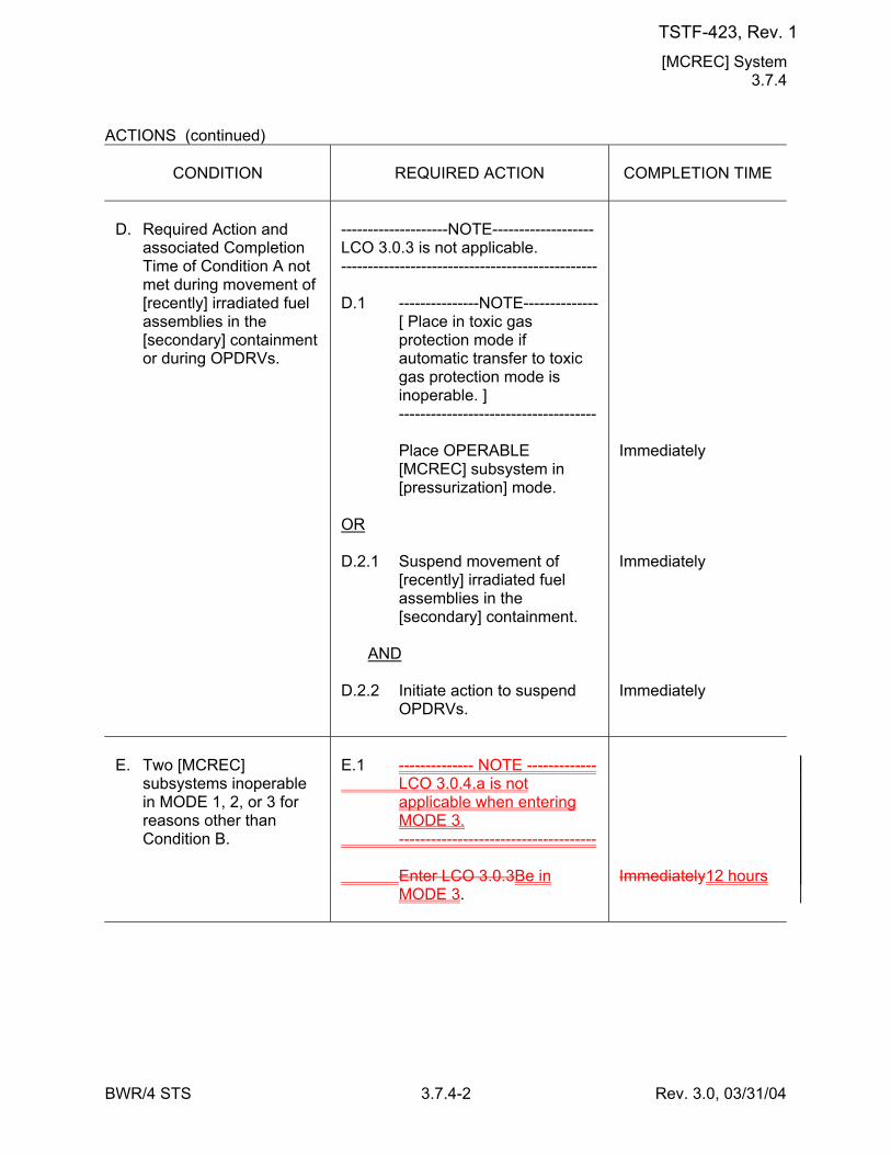
[MCREC] System 3.7.4
BWR/4 STS 3.7.4-2 Rev. 3.0, 03/31/04
ACTIONS (continued)
CONDITION
REQUIRED ACTION
COMPLETION TIME
D. Required Action and
associated Completion Time of Condition A not met during movement of [recently] irradiated fuel assemblies in the [secondary] containment or during OPDRVs.
--------------------NOTE------------------- LCO 3.0.3 is not applicable. ------------------------------------------------ D.1 ---------------NOTE-------------- [ Place in toxic gas
protection mode if automatic transfer to toxic gas protection mode is inoperable. ]
------------------------------------- Place OPERABLE
[MCREC] subsystem in [pressurization] mode.
OR D.2.1 Suspend movement of
[recently] irradiated fuel assemblies in the [secondary] containment.
AND D.2.2 Initiate action to suspend
OPDRVs.
Immediately Immediately Immediately
E. Two [MCREC]
subsystems inoperable in MODE 1, 2, or 3 for reasons other than Condition B.
E.1 -------------- NOTE ------------- LCO 3.0.4.a is not
applicable when entering MODE 3.
------------------------------------- Enter LCO 3.0.3Be in
MODE 3.
Immediately12 hours
TSTF-423, Rev. 1

[Control Room AC] System 3.7.5
BWR/4 STS 3.7.5-1 Rev. 3.0, 03/31/04
3.7 PLANT SYSTEMS 3.7.5 [Control Room Air Conditioning (AC)] System LCO 3.7.5 Two [control room AC] subsystems shall be OPERABLE. APPLICABILITY: MODES 1, 2, and 3, During movement of [recently] irradiated fuel assemblies in the
[secondary] containment, During operations with a potential for draining the reactor vessel
(OPDRVs). ACTIONS
CONDITION
REQUIRED ACTION
COMPLETION TIME
A. One [control room AC]
subsystem inoperable.
A.1 Restore [control room AC]
subsystem to OPERABLE status.
30 days
B. Required Action and
associated Completion Time of Condition A not met in MODE 1, 2, or 3.
B.1 -------------- NOTE ------------- LCO 3.0.4.a is not
applicable when entering MODE 3.
------------------------------------- Be in MODE 3. AND B.2 Be in MODE 4.
12 hours 36 hours
C. Required Action and
associated Completion Time of Condition A not met during movement of [recently] irradiated fuel assemblies in the [secondary] containment or during OPDRVs.
--------------------NOTE------------------- LCO 3.0.3 is not applicable. ------------------------------------------------ C.1 Place OPERABLE [control
room AC] subsystem in operation.
OR
Immediately
TSTF-423, Rev. 1
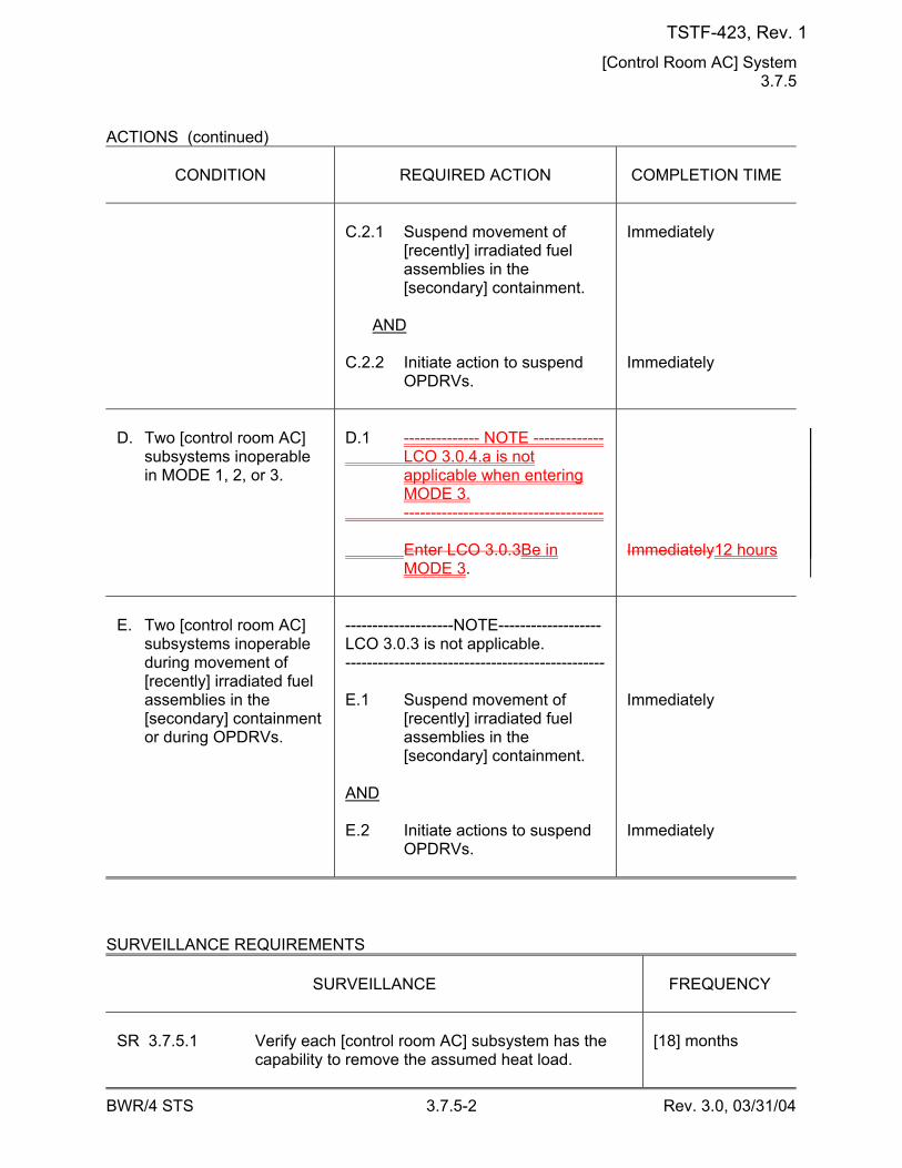
[Control Room AC] System 3.7.5
BWR/4 STS 3.7.5-2 Rev. 3.0, 03/31/04
ACTIONS (continued)
CONDITION
REQUIRED ACTION
COMPLETION TIME
C.2.1 Suspend movement of
[recently] irradiated fuel assemblies in the [secondary] containment.
AND C.2.2 Initiate action to suspend
OPDRVs.
Immediately Immediately
D. Two [control room AC]
subsystems inoperable in MODE 1, 2, or 3.
D.1 -------------- NOTE ------------- LCO 3.0.4.a is not
applicable when entering MODE 3.
------------------------------------- Enter LCO 3.0.3Be in
MODE 3.
Immediately12 hours
E. Two [control room AC]
subsystems inoperable during movement of [recently] irradiated fuel assemblies in the [secondary] containment or during OPDRVs.
--------------------NOTE------------------- LCO 3.0.3 is not applicable. ------------------------------------------------ E.1 Suspend movement of
[recently] irradiated fuel assemblies in the [secondary] containment.
AND E.2 Initiate actions to suspend
OPDRVs.
Immediately Immediately
SURVEILLANCE REQUIREMENTS
SURVEILLANCE
FREQUENCY
SR 3.7.5.1 Verify each [control room AC] subsystem has the
capability to remove the assumed heat load.
[18] months
TSTF-423, Rev. 1
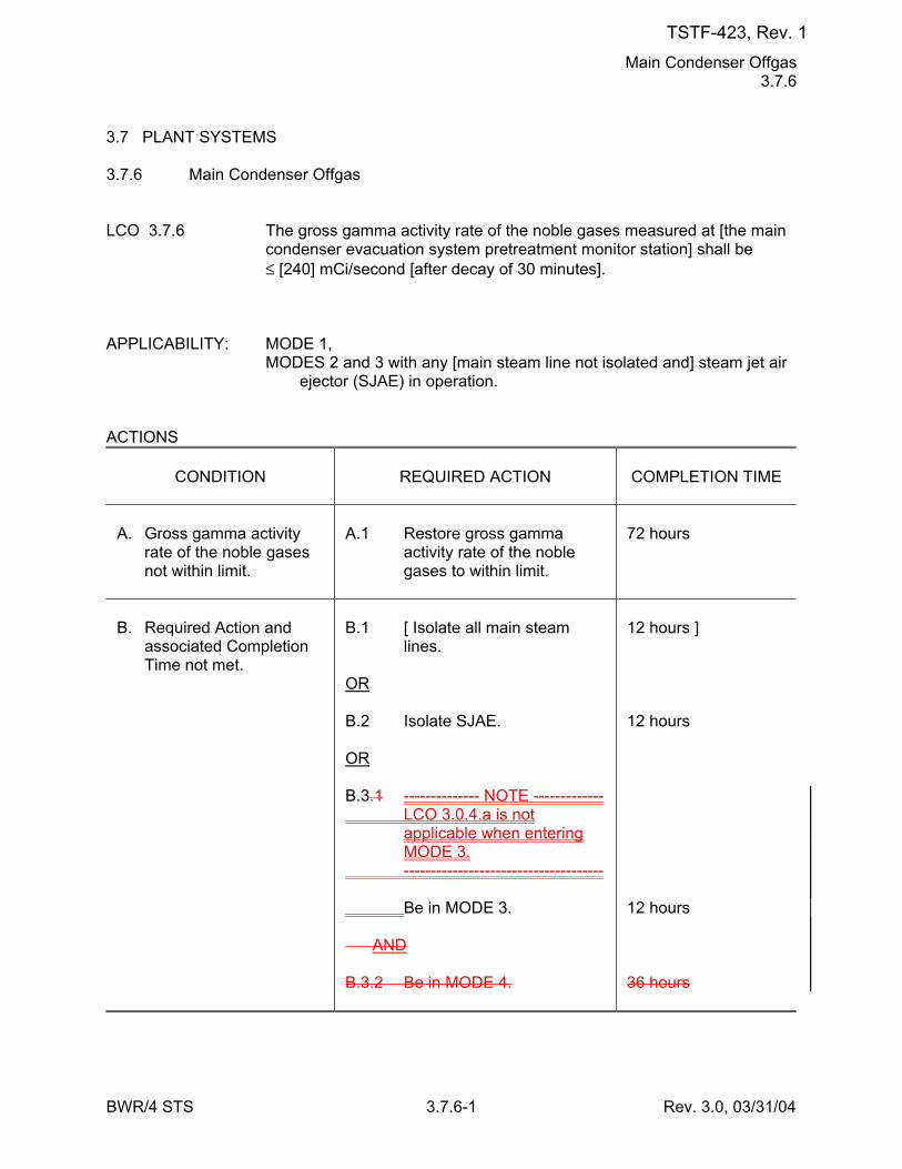
Main Condenser Offgas 3.7.6
BWR/4 STS 3.7.6-1 Rev. 3.0, 03/31/04
3.7 PLANT SYSTEMS 3.7.6 Main Condenser Offgas LCO 3.7.6 The gross gamma activity rate of the noble gases measured at [the main
condenser evacuation system pretreatment monitor station] shall be ≤ [240] mCi/second [after decay of 30 minutes].
APPLICABILITY: MODE 1, MODES 2 and 3 with any [main steam line not isolated and] steam jet air
ejector (SJAE) in operation. ACTIONS
CONDITION
REQUIRED ACTION
COMPLETION TIME
A. Gross gamma activity
rate of the noble gases not within limit.
A.1 Restore gross gamma
activity rate of the noble gases to within limit.
72 hours
B. Required Action and
associated Completion Time not met.
B.1 [ Isolate all main steam
lines. OR B.2 Isolate SJAE. OR B.3.1 -------------- NOTE ------------- LCO 3.0.4.a is not
applicable when entering MODE 3.
------------------------------------- Be in MODE 3. AND B.3.2 Be in MODE 4.
12 hours ] 12 hours 12 hours 36 hours
TSTF-423, Rev. 1
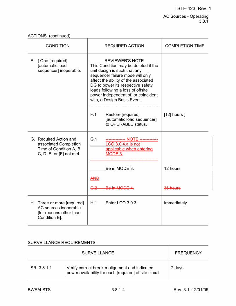
AC Sources - Operating 3.8.1
BWR/4 STS 3.8.1-4 Rev. 3.1, 12/01/05
ACTIONS (continued)
CONDITION
REQUIRED ACTION
COMPLETION TIME
F. [ One [required]
[automatic load sequencer] inoperable.
----------REVIEWER’S NOTE---------- This Condition may be deleted if the unit design is such that any sequencer failure mode will only affect the ability of the associated DG to power its respective safety loads following a loss of offsite power independent of, or coincident with, a Design Basis Event. ------------------------------------------------ F.1 Restore [required]
[automatic load sequencer] to OPERABLE status.
[12] hours ]
G. Required Action and
associated Completion Time of Condition A, B, C, D, E, or [F] not met.
G.1 -------------- NOTE ------------- LCO 3.0.4.a is not
applicable when entering MODE 3.
------------------------------------- Be in MODE 3. AND G.2 Be in MODE 4.
12 hours 36 hours
H. Three or more [required]
AC sources inoperable [for reasons other than Condition E].
H.1 Enter LCO 3.0.3.
Immediately
SURVEILLANCE REQUIREMENTS
SURVEILLANCE
FREQUENCY
SR 3.8.1.1 Verify correct breaker alignment and indicated
power availability for each [required] offsite circuit.
7 days
TSTF-423, Rev. 1
DC Sources - Operating 3.8.4
BWR/4 STS 3.8.4-2 Rev. 3.0, 03/31/04
ACTIONS (continued)
CONDITION
REQUIRED ACTION
COMPLETION TIME
D. Required Action and
Associated Completion Time of Condition A[, B, or C] not met for station service DC subsystem.
D.1 -------------- NOTE ------------- LCO 3.0.4.a is not
applicable when entering MODE 3.
------------------------------------- Be in MODE 3. AND D.2 Be in MODE 4.
12 hours 36 hours
E. [ Required Action and
associated Completion Time of Condition A[, B, or C] not met for DG DC subsystem.
E.1 Declare associated DG
inoperable.
Immediately ]
SURVEILLANCE REQUIREMENTS
SURVEILLANCE
FREQUENCY
SR 3.8.4.1 Verify battery terminal voltage is greater than or
equal to the minimum established float voltage.
7 days
SR 3.8.4.2 Verify each required battery charger supplies
≥ [400 amps for station service subsystems, and ≥ 100 amps for DG subsystems] at greater than or equal to the minimum established float voltage for ≥ [4] hours.
OR Verify each battery charger can recharge the battery
to the fully charged state within [24] hours while supplying the largest combined demands of the various continuous steady state loads, after a battery discharge to the bounding design basis event discharge state.
[18 months]
TSTF-423, Rev. 1
Inverters - Operating 3.8.7
BWR/4 STS 3.8.7-1 Rev. 3.0, 03/31/04
3.8 ELECTRICAL POWER SYSTEMS 3.8.7 Inverters - Operating LCO 3.8.7 The [Division 1] and [Division 2] inverters shall be OPERABLE. ---------------------------------------------NOTE-------------------------------------------- [ One/two] inverter[s] may be disconnected from [its/their] associated DC
bus for ≤ [24] hours to perform an equalizing charge on [its/their] associated [common] battery, provided:
a. The associated AC vital bus[es] [is/are] energized from [its/their]
[Class 1E constant voltage transformers] [inverter using internal AC source] and
b. All other AC vital buses are energized from their associated
OPERABLE inverters. ] -------------------------------------------------------------------------------------------------- APPLICABILITY: MODES 1, 2, and 3. ACTIONS
CONDITION
REQUIRED ACTION
COMPLETION TIME
A. One [required] inverter
inoperable.
A.1 ---------------NOTE-------------- Enter applicable Conditions
and Required Actions of LCO 3.8.9, "Distribution Systems - Operating" with any AC vital bus de-energized.
------------------------------------- Restore inverter to
OPERABLE status.
24 hours
B. Required Action and
associated Completion Time not met.
B.1 -------------- NOTE ------------- LCO 3.0.4.a is not
applicable when entering MODE 3.
------------------------------------- Be in MODE 3.
12 hours
TSTF-423, Rev. 1
Inverters - Operating 3.8.7
BWR/4 STS 3.8.7-2 Rev. 3.0, 03/31/04
CONDITION
REQUIRED ACTION
COMPLETION TIME
AND B.2 Be in MODE 4.
36 hours
TSTF-423, Rev. 1
Distribution Systems - Operating 3.8.9
BWR/4 STS 3.8.9-2 Rev. 3.1, 12/01/05
ACTIONS (continued)
CONDITION
REQUIRED ACTION
COMPLETION TIME
D. Required Action and
associated Completion Time of Condition A, B, or C not met.
D.1 -------------- NOTE ------------- LCO 3.0.4.a is not
applicable when entering MODE 3.
------------------------------------- Be in MODE 3. AND D.2 Be in MODE 4.
12 hours 36 hours
E. [ One or more DG DC
electrical power distribution subsystems inoperable.
E.1 Declare associated DG(s)
inoperable.
Immediately ]
F. Two or more electrical
power distribution subsystems inoperable that result in a loss of function.
F.1 Enter LCO 3.0.3.
Immediately
SURVEILLANCE REQUIREMENTS
SURVEILLANCE
FREQUENCY
SR 3.8.9.1 Verify correct breaker alignments and voltage to
[required] AC, DC, [and AC vital bus] electrical power distribution subsystems.
7 days
TSTF-423, Rev. 1
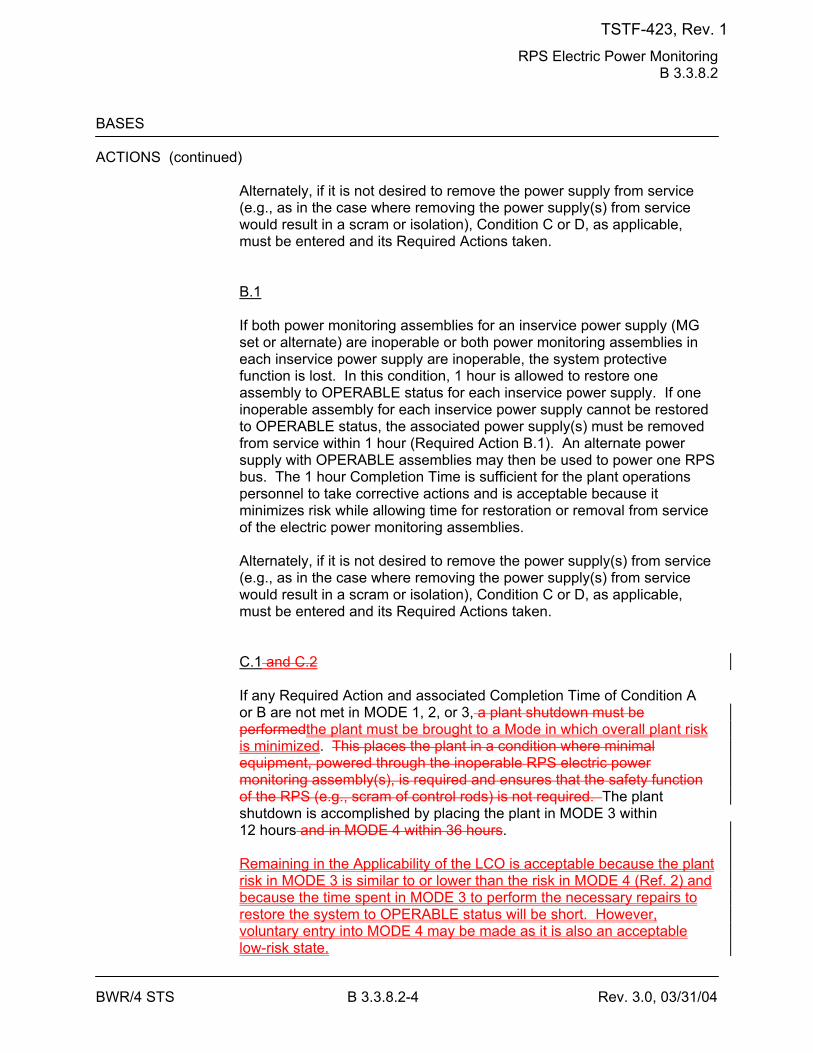
RPS Electric Power Monitoring B 3.3.8.2
BWR/4 STS B 3.3.8.2-4 Rev. 3.0, 03/31/04
BASES ACTIONS (continued)
Alternately, if it is not desired to remove the power supply from service (e.g., as in the case where removing the power supply(s) from service would result in a scram or isolation), Condition C or D, as applicable, must be entered and its Required Actions taken. B.1 If both power monitoring assemblies for an inservice power supply (MG set or alternate) are inoperable or both power monitoring assemblies in each inservice power supply are inoperable, the system protective function is lost. In this condition, 1 hour is allowed to restore one assembly to OPERABLE status for each inservice power supply. If one inoperable assembly for each inservice power supply cannot be restored to OPERABLE status, the associated power supply(s) must be removed from service within 1 hour (Required Action B.1). An alternate power supply with OPERABLE assemblies may then be used to power one RPS bus. The 1 hour Completion Time is sufficient for the plant operations personnel to take corrective actions and is acceptable because it minimizes risk while allowing time for restoration or removal from service of the electric power monitoring assemblies. Alternately, if it is not desired to remove the power supply(s) from service (e.g., as in the case where removing the power supply(s) from service would result in a scram or isolation), Condition C or D, as applicable, must be entered and its Required Actions taken. C.1 and C.2 If any Required Action and associated Completion Time of Condition A or B are not met in MODE 1, 2, or 3, a plant shutdown must be performedthe plant must be brought to a Mode in which overall plant risk is minimized. This places the plant in a condition where minimal equipment, powered through the inoperable RPS electric power monitoring assembly(s), is required and ensures that the safety function of the RPS (e.g., scram of control rods) is not required. The plant shutdown is accomplished by placing the plant in MODE 3 within 12 hours and in MODE 4 within 36 hours. Remaining in the Applicability of the LCO is acceptable because the plant risk in MODE 3 is similar to or lower than the risk in MODE 4 (Ref. 2) and because the time spent in MODE 3 to perform the necessary repairs to restore the system to OPERABLE status will be short. However, voluntary entry into MODE 4 may be made as it is also an acceptable low-risk state.
TSTF-423, Rev. 1

RPS Electric Power Monitoring B 3.3.8.2
BWR/4 STS B 3.3.8.2-5 Rev. 3.0, 03/31/04
Required Action C.1 is modified by a Note that states that LCO 3.0.4.a is not applicable when entering MODE 3. This Note prohibits the use of LCO 3.0.4.a to enter MODE 3 during startup with the LCO not met. However, there is no restriction on the use of LCO 3.0.4.b, if applicable, because LCO 3.0.4.b requires performance of a risk assessment addressing inoperable systems and components, consideration of the results, determination of the acceptability of entering MODE 3, and establishment of risk management actions, if appropriate. LCO 3.0.4 is not applicable to, and the Note does not preclude, changes in MODES or other specified conditions in the Applicability that are required to comply with ACTIONS or that are part of a shutdown of the unit. The allowed Completion Times are is reasonable, based on operating experience, to reach the required plant conditions from full power conditions in an orderly manner and without challenging plant systems.
TSTF-423, Rev. 1
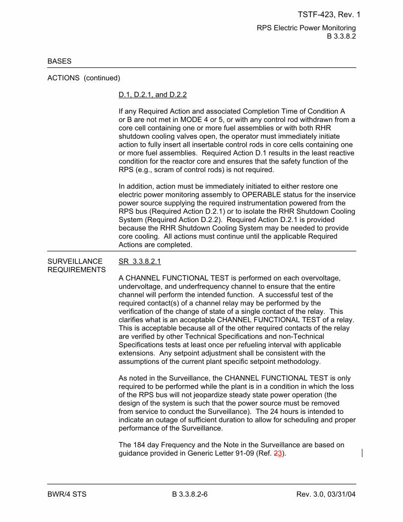
RPS Electric Power Monitoring B 3.3.8.2
BWR/4 STS B 3.3.8.2-6 Rev. 3.0, 03/31/04
BASES ACTIONS (continued)
D.1, D.2.1, and D.2.2 If any Required Action and associated Completion Time of Condition A or B are not met in MODE 4 or 5, or with any control rod withdrawn from a core cell containing one or more fuel assemblies or with both RHR shutdown cooling valves open, the operator must immediately initiate action to fully insert all insertable control rods in core cells containing one or more fuel assemblies. Required Action D.1 results in the least reactive condition for the reactor core and ensures that the safety function of the RPS (e.g., scram of control rods) is not required. In addition, action must be immediately initiated to either restore one electric power monitoring assembly to OPERABLE status for the inservice power source supplying the required instrumentation powered from the RPS bus (Required Action D.2.1) or to isolate the RHR Shutdown Cooling System (Required Action D.2.2). Required Action D.2.1 is provided because the RHR Shutdown Cooling System may be needed to provide core cooling. All actions must continue until the applicable Required Actions are completed.
SURVEILLANCE SR 3.3.8.2.1 REQUIREMENTS
A CHANNEL FUNCTIONAL TEST is performed on each overvoltage, undervoltage, and underfrequency channel to ensure that the entire channel will perform the intended function. A successful test of the required contact(s) of a channel relay may be performed by the verification of the change of state of a single contact of the relay. This clarifies what is an acceptable CHANNEL FUNCTIONAL TEST of a relay. This is acceptable because all of the other required contacts of the relay are verified by other Technical Specifications and non-Technical Specifications tests at least once per refueling interval with applicable extensions. Any setpoint adjustment shall be consistent with the assumptions of the current plant specific setpoint methodology. As noted in the Surveillance, the CHANNEL FUNCTIONAL TEST is only required to be performed while the plant is in a condition in which the loss of the RPS bus will not jeopardize steady state power operation (the design of the system is such that the power source must be removed from service to conduct the Surveillance). The 24 hours is intended to indicate an outage of sufficient duration to allow for scheduling and proper performance of the Surveillance. The 184 day Frequency and the Note in the Surveillance are based on guidance provided in Generic Letter 91-09 (Ref. 23).
TSTF-423, Rev. 1
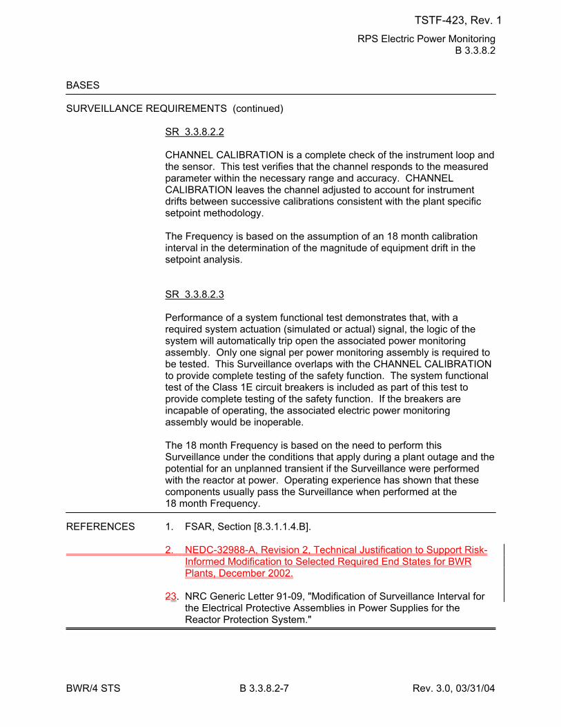
RPS Electric Power Monitoring B 3.3.8.2
BWR/4 STS B 3.3.8.2-7 Rev. 3.0, 03/31/04
BASES SURVEILLANCE REQUIREMENTS (continued)
SR 3.3.8.2.2 CHANNEL CALIBRATION is a complete check of the instrument loop and the sensor. This test verifies that the channel responds to the measured parameter within the necessary range and accuracy. CHANNEL CALIBRATION leaves the channel adjusted to account for instrument drifts between successive calibrations consistent with the plant specific setpoint methodology. The Frequency is based on the assumption of an 18 month calibration interval in the determination of the magnitude of equipment drift in the setpoint analysis. SR 3.3.8.2.3 Performance of a system functional test demonstrates that, with a required system actuation (simulated or actual) signal, the logic of the system will automatically trip open the associated power monitoring assembly. Only one signal per power monitoring assembly is required to be tested. This Surveillance overlaps with the CHANNEL CALIBRATION to provide complete testing of the safety function. The system functional test of the Class 1E circuit breakers is included as part of this test to provide complete testing of the safety function. If the breakers are incapable of operating, the associated electric power monitoring assembly would be inoperable. The 18 month Frequency is based on the need to perform this Surveillance under the conditions that apply during a plant outage and the potential for an unplanned transient if the Surveillance were performed with the reactor at power. Operating experience has shown that these components usually pass the Surveillance when performed at the 18 month Frequency.
REFERENCES 1. FSAR, Section [8.3.1.1.4.B]. 2. NEDC-32988-A, Revision 2, Technical Justification to Support Risk-
Informed Modification to Selected Required End States for BWR Plants, December 2002.
23. NRC Generic Letter 91-09, "Modification of Surveillance Interval for
the Electrical Protective Assemblies in Power Supplies for the Reactor Protection System."
TSTF-423, Rev. 1
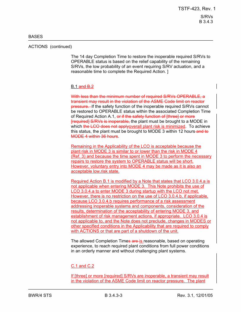
S/RVs B 3.4.3
BWR/4 STS B 3.4.3-3 Rev. 3.1, 12/01/05
BASES ACTIONS (continued)
The 14 day Completion Time to restore the inoperable required S/RVs to OPERABLE status is based on the relief capability of the remaining S/RVs, the low probability of an event requiring S/RV actuation, and a reasonable time to complete the Required Action. ] B.1 and B.2 With less than the minimum number of required S/RVs OPERABLE, a transient may result in the violation of the ASME Code limit on reactor pressure. If the safety function of the inoperable required S/RVs cannot be restored to OPERABLE status within the associated Completion Time of Required Action A.1, or if the safety function of [three] or more [required] S/RVs is inoperable, the plant must be brought to a MODE in which the LCO does not applyoverall plant risk is minimized. To achieve this status, the plant must be brought to MODE 3 within 12 hours and to MODE 4 within 36 hours. Remaining in the Applicability of the LCO is acceptable because the plant·risk in MODE 3 is similar to or lower than the risk in MODE 4 (Ref. 3) and because the time spent in MODE 3 to perform the necessary repairs to restore the system to OPERABLE status will be short. However, voluntary entry into MODE 4 may be made as it is also an acceptable low.risk state. Required Action B.1 is modified by a Note that states that LCO 3.0.4.a is not applicable when entering MODE 3. This Note prohibits the use of LCO 3.0.4.a to enter MODE 3 during startup with the LCO not met. However, there is no restriction on the use of LCO 3.0.4.b, if applicable, because LCO 3.0.4.b requires performance of a risk assessment addressing inoperable systems and components, consideration of the results, determination of the acceptability of entering MODE 3, and establishment of risk management actions, if appropriate. LCO 3.0.4 is not applicable to, and the Note does not preclude, changes in MODES or other specified conditions in the Applicability that are required to comply with ACTIONS or that are part of a shutdown of the unit. The allowed Completion Times are is reasonable, based on operating experience, to reach required plant conditions from full power conditions in an orderly manner and without challenging plant systems.
C.1 and C.2
If [three] or more [required] S/RVs are inoperable, a transient may result in the violation of the ASME Code limit on reactor pressure. The plant
TSTF-423, Rev. 1
S/RVs B 3.4.3
BWR/4 STS B 3.4.3-4 Rev. 3.1, 12/01/05
must be brought to a MODE in which the LCO does not apply. To achieve this status, the plant must be brought to MODE 3 within 12 hours and to MODE 4 within 36 hours. The allowed Completion Times are reasonable, based on operating experience, to reach required plant conditions from full power conditions in an orderly manner and without challenging plant systems.
SURVEILLANCE SR 3.4.3.1 REQUIREMENTS
This Surveillance requires that the [required] S/RVs will open at the pressures assumed in the safety analysis of Reference 1. The demonstration of the S/RV safe lift settings must be performed during shutdown, since this is a bench test, [to be done in accordance with the Inservice Testing Program]. The lift setting pressure shall correspond to ambient conditions of the valves at nominal operating temperatures and pressures. The S/RV setpoint is ± [3]% for OPERABILITY; however, the valves are reset to ± 1% during the Surveillance to allow for drift. [A Note is provided to allow up to [two] of the required [11] S/RVs to be physically replaced with S/RVs with lower setpoints. This provides operational flexibility which maintains the assumptions in the over-pressure analysis.] The 18 month Frequency was selected because this Surveillance must be performed during shutdown conditions and is based on the time between refuelings.
TSTF-423, Rev. 1
S/RVs B 3.4.3
BWR/4 STS B 3.4.3-5 Rev. 3.1, 12/01/05
BASES SURVEILLANCE REQUIREMENTS (continued)
SR 3.4.3.2 A manual actuation of each [required] S/RV is performed to verify that, mechanically, the valve is functioning properly and no blockage exists in the valve discharge line. This can be demonstrated by the response of the turbine control valves or bypass valves, by a change in the measured steam flow, or by any other method suitable to verify steam flow. Adequate reactor steam dome pressure must be available to perform this test to avoid damaging the valve. Also, adequate steam flow must be passing through the main turbine or turbine bypass valves to continue to control reactor pressure when the S/RVs divert steam flow upon opening. Sufficient time is therefore allowed after the required pressure and flow are achieved to perform this test. Adequate pressure at which this test is to be performed is [920] psig (the pressure recommended by the valve manufacturer). Adequate steam flow is represented by [at least 1.25 turbine bypass valves open, or total steam flow ≥106 lb/hr]. Plant startup is allowed prior to performing this test because valve OPERABILITY and the setpoints for overpressure protection are verified, per ASME Code requirements, prior to valve installation. Therefore, this SR is modified by a Note that states the Surveillance is not required to be performed until 12 hours after reactor steam pressure and flow are adequate to perform the test. The 12 hours allowed for manual actuation after the required pressure is reached is sufficient to achieve stable conditions for testing and provides a reasonable time to complete the SR. If a valve fails to actuate due only to the failure of the solenoid but is capable of opening on overpressure, the safety function of the S/RV is considered OPERABLE. The [18] month on a STAGGERED TEST BASIS Frequency ensures that each solenoid for each S/RV is alternately tested. The 18 month Frequency was developed based on the S/RV tests required by the ASME Boiler and Pressure Vessel Code (Ref. 34). Operating experience has shown that these components usually pass the Surveillance when performed at the 18 month Frequency. Therefore, the Frequency was concluded to be acceptable from a reliability standpoint.
REFERENCES 1. FSAR, Section [5.2.2.2.4]. 2. FSAR, Section [15]. 3. NEDC-32988-A, Revision 2, Technical Justification to Support Risk-
Informed Modification to Selected Required End States for BWR Plants, December 2002.
34. ASME Code for Operation and Maintenance of Nuclear Power
Plants.
TSTF-423, Rev. 1
ECCS - Operating 3.5.1
BWR/4 STS B 3.5.1-6 Rev. 3.1, 12/01/05
BASES ACTIONS (continued)
is based on a reliability study (Ref. 12) that evaluated the impact on ECCS availability, assuming various components and subsystems were taken out of service. The results were used to calculate the average availability of ECCS equipment needed to mitigate the consequences of a LOCA as a function of allowed outage times (i.e., Completion Times). B.1 and B.2 If the inoperable low pressure ECCS subsystem cannot be restored to OPERABLE status within the associated Completion Time, the plant must be brought to a MODE in which the LCO does not applyoverall plant risk is minimized. To achieve this status, the plant must be brought to at least MODE 3 within 12 hours and to MODE 4 within 36 hours. Remaining in the Applicability of the LCO is acceptable because the plant risk in MODE 3 is similar to or lower than the risk in MODE 4 (Ref. 13) and because the time spent in MODE 3 to perform the necessary repairs to restore the system to OPERABLE status will be short. However, voluntary entry into MODE 4 may be made as it is also an acceptable low-risk state. Required Action B.1 is modified by a Note that states that LCO 3.0.4.a is not applicable when entering MODE 3. This Note prohibits the use of LCO 3.0.4.a to enter MODE 3 during startup with the LCO not met. However, there is no restriction on the use of LCO 3.0.4.b, if applicable, because LCO 3.0.4.b requires performance of a risk assessment addressing inoperable systems and components, consideration of the results, determination of the acceptability of entering MODE 3, and establishment of risk management actions, if appropriate. LCO 3.0.4 is not applicable to, and the Note does not preclude, changes in MODES or other specified conditions in the Applicability that are required to comply with ACTIONS or that are part of a shutdown of the unit. The allowed Completion Times are is reasonable, based on operating experience, to reach the required plant conditions from full power conditions in an orderly manner and without challenging plant systems. C.1 and C.2 If the HPCI System is inoperable and the RCIC System is verified to be OPERABLE, the HPCI System must be restored to OPERABLE status within 14 days. In this Condition, adequate core cooling is ensured by the OPERABILITY of the redundant and diverse low pressure ECCS injection/spray subsystems in conjunction with ADS. Also, the RCIC
TSTF-423, Rev. 1
ECCS - Operating 3.5.1
BWR/4 STS B 3.5.1-8 Rev. 3.1, 12/01/05
BASES ACTIONS (continued)
D.1 and D.2 If any one low pressure ECCS injection/spray subsystem, or one LPCI pump in both LPCI subsystems, is inoperable in addition to an inoperable HPCI System, the inoperable low pressure ECCS injection/spray subsystem or the HPCI System must be restored to OPERABLE status within 72 hours. In this Condition, adequate core cooling is ensured by the OPERABILITY of the ADS and the remaining low pressure ECCS subsystems. However, the overall ECCS reliability is significantly reduced because a single failure in one of the remaining OPERABLE subsystems concurrent with a design basis LOCA may result in the ECCS not being able to perform its intended safety function. Since both a high pressure system (HPCI) and a low pressure subsystem are inoperable, a more restrictive Completion Time of 72 hours is required to restore either the HPCI System or the low pressure ECCS injection/spray subsystem to OPERABLE status. This Completion Time is based on a reliability study cited in Reference 12 and has been found to be acceptable through operating experience. E.1 The LCO requires seven ADS valves to be OPERABLE in order to provide the ADS function. Reference 13 14 contains the results of an analysis that evaluated the effect of one ADS valve being out of service. Per this analysis, operation of only six ADS valves will provide the required depressurization. However, overall reliability of the ADS is reduced, because a single failure in the OPERABLE ADS valves could result in a reduction in depressurization capability. Therefore, operation is only allowed for a limited time. The 14 day Completion Time is based on a reliability study cited in Reference 12 and has been found to be acceptable through operating experience. F.1 and F.2 If any one low pressure ECCS injection/spray subsystem, or one LPCI pump in both LPCI subsystems, is inoperable in addition to one inoperable ADS valve, adequate core cooling is ensured by the OPERABILITY of HPCI and the remaining low pressure ECCS injection/spray subsystem. However, overall ECCS reliability is reduced because a single active component failure concurrent with a design basis
TSTF-423, Rev. 1
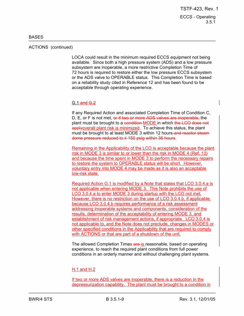
ECCS - Operating 3.5.1
BWR/4 STS B 3.5.1-9 Rev. 3.1, 12/01/05
BASES ACTIONS (continued)
LOCA could result in the minimum required ECCS equipment not being available. Since both a high pressure system (ADS) and a low pressure subsystem are inoperable, a more restrictive Completion Time of 72 hours is required to restore either the low pressure ECCS subsystem or the ADS valve to OPERABLE status. This Completion Time is based on a reliability study cited in Reference 12 and has been found to be acceptable through operating experience. G.1 and G.2 If any Required Action and associated Completion Time of Condition C, D, E, or F is not met, or if two or more ADS valves are inoperable, the plant must be brought to a condition MODE in which the LCO does not applyoverall plant risk is minimized. To achieve this status, the plant must be brought to at least MODE 3 within 12 hours and reactor steam dome pressure reduced to ≤ 150 psig within 36 hours. Remaining in the Applicability of the LCO is acceptable because the plant risk in MODE 3 is similar to or lower than the risk in MODE 4 (Ref. 13) and because the time spent in MODE 3 to perform the necessary repairs to restore the system to OPERABLE status will be short. However, voluntary entry into MODE 4 may be made as it is also an acceptable low-risk state. Required Action G.1 is modified by a Note that states that LCO 3.0.4.a is not applicable when entering MODE 3. This Note prohibits the use of LCO 3.0.4.a to enter MODE 3 during startup with the LCO not met. However, there is no restriction on the use of LCO 3.0.4.b, if applicable, because LCO 3.0.4.b requires performance of a risk assessment addressing inoperable systems and components, consideration of the results, determination of the acceptability of entering MODE 3, and establishment of risk management actions, if appropriate. LCO 3.0.4 is not applicable to, and the Note does not preclude, changes in MODES or other specified conditions in the Applicability that are required to comply with ACTIONS or that are part of a shutdown of the unit. The allowed Completion Times are is reasonable, based on operating experience, to reach the required plant conditions from full power conditions in an orderly manner and without challenging plant systems. H.1 and H.2 If two or more ADS valves are inoperable, there is a reduction in the depressurization capability. The plant must be brought to a condition in
TSTF-423, Rev. 1
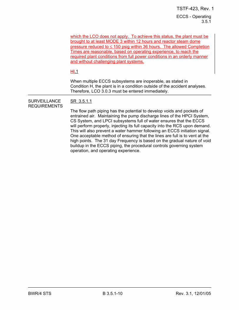
ECCS - Operating 3.5.1
BWR/4 STS B 3.5.1-10 Rev. 3.1, 12/01/05
which the LCO does not apply. To achieve this status, the plant must be brought to at least MODE 3 within 12 hours and reactor steam dome pressure reduced to ≤ 150 psig within 36 hours. The allowed Completion Times are reasonable, based on operating experience, to reach the required plant conditions from full power conditions in an orderly manner and without challenging plant systems. HI.1 When multiple ECCS subsystems are inoperable, as stated in Condition H, the plant is in a condition outside of the accident analyses. Therefore, LCO 3.0.3 must be entered immediately.
SURVEILLANCE SR 3.5.1.1 REQUIREMENTS
The flow path piping has the potential to develop voids and pockets of entrained air. Maintaining the pump discharge lines of the HPCI System, CS System, and LPCI subsystems full of water ensures that the ECCS will perform properly, injecting its full capacity into the RCS upon demand. This will also prevent a water hammer following an ECCS initiation signal. One acceptable method of ensuring that the lines are full is to vent at the high points. The 31 day Frequency is based on the gradual nature of void buildup in the ECCS piping, the procedural controls governing system operation, and operating experience.
TSTF-423, Rev. 1
ECCS - Operating 3.5.1
BWR/4 STS B 3.5.1-16 Rev. 3.1, 12/01/05
BASES SURVEILLANCE REQUIREMENTS (continued)
perform this SR. Adequate pressure at which this SR is to be performed is [920 psig] (the pressure recommended by the valve manufacturer). Adequate steam flow is represented by [at least 1.25 turbine bypass valves open, or total steam flow ≥ 106 lb/hr]. Reactor startup is allowed prior to performing this SR because valve OPERABILITY and the setpoints for overpressure protection are verified, per ASME requirements, prior to valve installation. Therefore, this SR is modified by a Note that states the Surveillance is not required to be performed until 12 hours after reactor steam pressure and flow are adequate to perform the test. The 12 hours allowed for manual actuation after the required pressure is reached is sufficient to achieve stable conditions and provides adequate time to complete the Surveillance. SR 3.5.1.11 and the LOGIC SYSTEM FUNCTIONAL TEST performed in LCO 3.3.5.1 overlap this Surveillance to provide complete testing of the assumed safety function. The Frequency of 18 months on a STAGGERED TEST BASIS ensures that both solenoids for each ADS valve are alternately tested. The Frequency is based on the need to perform the Surveillance under the conditions that apply just prior to or during a startup from a plant outage. Operating experience has shown that these components usually pass the SR when performed at the 18 month Frequency, which is based on the refueling cycle. Therefore, the Frequency was concluded to be acceptable from a reliability standpoint.
REFERENCES 1. FSAR, Section [6.3.2.2.3]. 2. FSAR, Section [6.3.2.2.4]. 3. FSAR, Section [6.3.2.2.1]. 4. FSAR, Section [6.3.2.2.2]. 5. FSAR, Section [15.2.8]. 6. FSAR, Section [15.6.4]. 7. FSAR, Section [15.6.5]. 8. 10 CFR 50, Appendix K. 9. FSAR, Section [6.3.3].
TSTF-423, Rev. 1
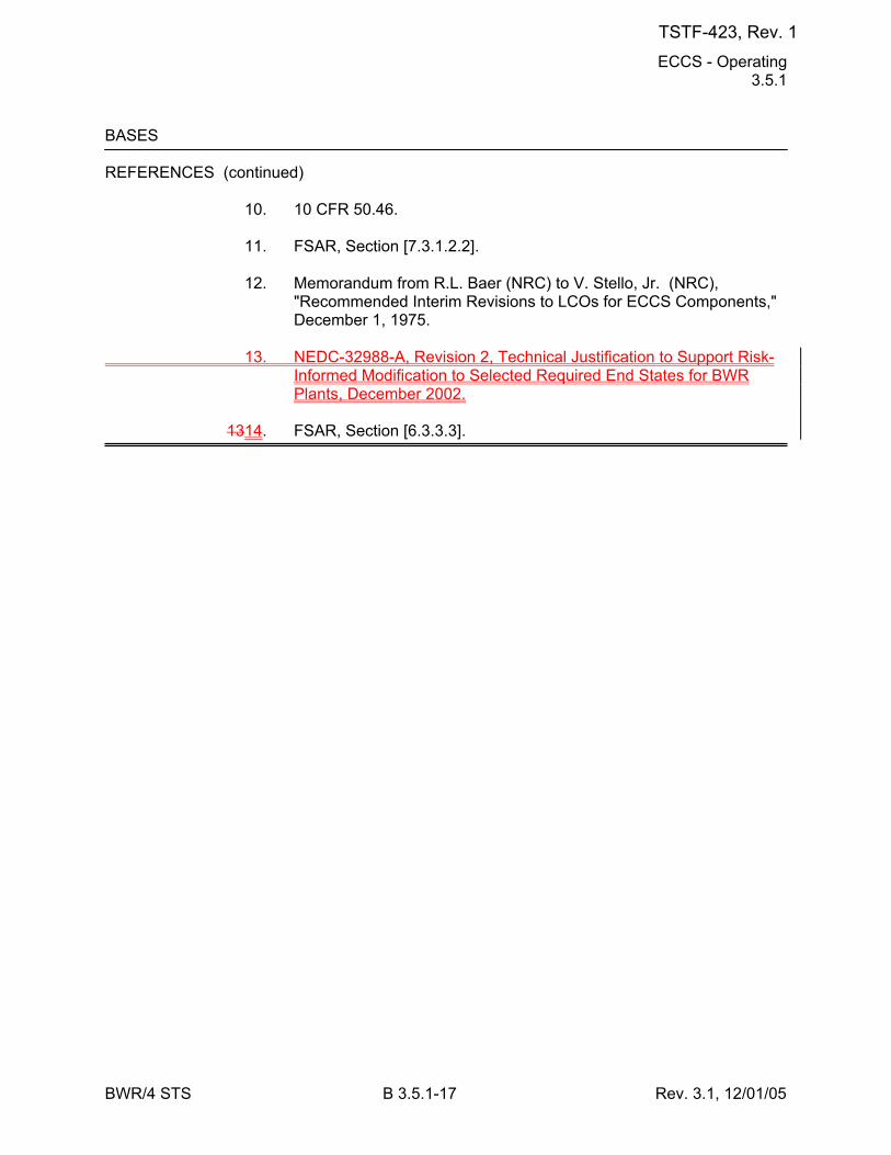
ECCS - Operating 3.5.1
BWR/4 STS B 3.5.1-17 Rev. 3.1, 12/01/05
BASES REFERENCES (continued) 10. 10 CFR 50.46. 11. FSAR, Section [7.3.1.2.2]. 12. Memorandum from R.L. Baer (NRC) to V. Stello, Jr. (NRC),
"Recommended Interim Revisions to LCOs for ECCS Components," December 1, 1975.
13. NEDC-32988-A, Revision 2, Technical Justification to Support Risk-
Informed Modification to Selected Required End States for BWR Plants, December 2002.
1314. FSAR, Section [6.3.3.3].
TSTF-423, Rev. 1
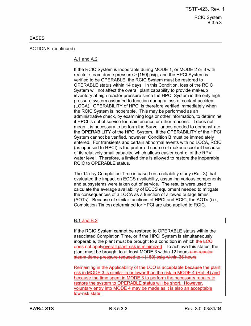
RCIC System B 3.5.3
BWR/4 STS B 3.5.3-3 Rev. 3.0, 03/31/04
BASES ACTIONS (continued) A.1 and A.2
If the RCIC System is inoperable during MODE 1, or MODE 2 or 3 with reactor steam dome pressure > [150] psig, and the HPCI System is verified to be OPERABLE, the RCIC System must be restored to OPERABLE status within 14 days. In this Condition, loss of the RCIC System will not affect the overall plant capability to provide makeup inventory at high reactor pressure since the HPCI System is the only high pressure system assumed to function during a loss of coolant accident (LOCA). OPERABILITY of HPCI is therefore verified immediately when the RCIC System is inoperable. This may be performed as an administrative check, by examining logs or other information, to determine if HPCI is out of service for maintenance or other reasons. It does not mean it is necessary to perform the Surveillances needed to demonstrate the OPERABILITY of the HPCI System. If the OPERABILITY of the HPCI System cannot be verified, however, Condition B must be immediately entered. For transients and certain abnormal events with no LOCA, RCIC (as opposed to HPCI) is the preferred source of makeup coolant because of its relatively small capacity, which allows easier control of the RPV water level. Therefore, a limited time is allowed to restore the inoperable RCIC to OPERABLE status. The 14 day Completion Time is based on a reliability study (Ref. 3) that evaluated the impact on ECCS availability, assuming various components and subsystems were taken out of service. The results were used to calculate the average availability of ECCS equipment needed to mitigate the consequences of a LOCA as a function of allowed outage times (AOTs). Because of similar functions of HPCI and RCIC, the AOTs (i.e., Completion Times) determined for HPCI are also applied to RCIC. B.1 and B.2 If the RCIC System cannot be restored to OPERABLE status within the associated Completion Time, or if the HPCI System is simultaneously inoperable, the plant must be brought to a condition in which the LCO does not applyoverall plant risk is minimized. To achieve this status, the plant must be brought to at least MODE 3 within 12 hours and reactor steam dome pressure reduced to ≤ [150] psig within 36 hours. Remaining in the Applicability of the LCO is acceptable because the plant risk in MODE 3 is similar to or lower than the risk in MODE 4 (Ref. 4) and because the time spent in MODE 3 to perform the necessary repairs to restore the system to OPERABLE status will be short. However, voluntary entry into MODE 4 may be made as it is also an acceptable low-risk state.
TSTF-423, Rev. 1
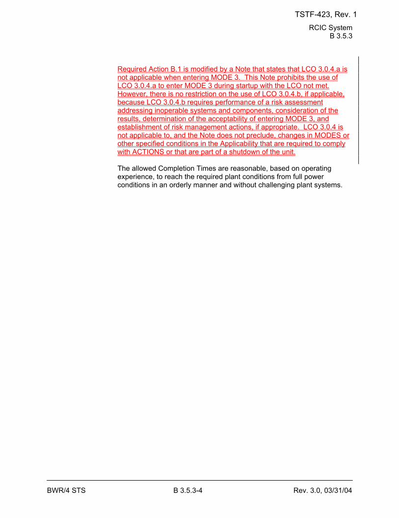
RCIC System B 3.5.3
BWR/4 STS B 3.5.3-4 Rev. 3.0, 03/31/04
Required Action B.1 is modified by a Note that states that LCO 3.0.4.a is not applicable when entering MODE 3. This Note prohibits the use of LCO 3.0.4.a to enter MODE 3 during startup with the LCO not met. However, there is no restriction on the use of LCO 3.0.4.b, if applicable, because LCO 3.0.4.b requires performance of a risk assessment addressing inoperable systems and components, consideration of the results, determination of the acceptability of entering MODE 3, and establishment of risk management actions, if appropriate. LCO 3.0.4 is not applicable to, and the Note does not preclude, changes in MODES or other specified conditions in the Applicability that are required to comply with ACTIONS or that are part of a shutdown of the unit. The allowed Completion Times are reasonable, based on operating experience, to reach the required plant conditions from full power conditions in an orderly manner and without challenging plant systems.
TSTF-423, Rev. 1
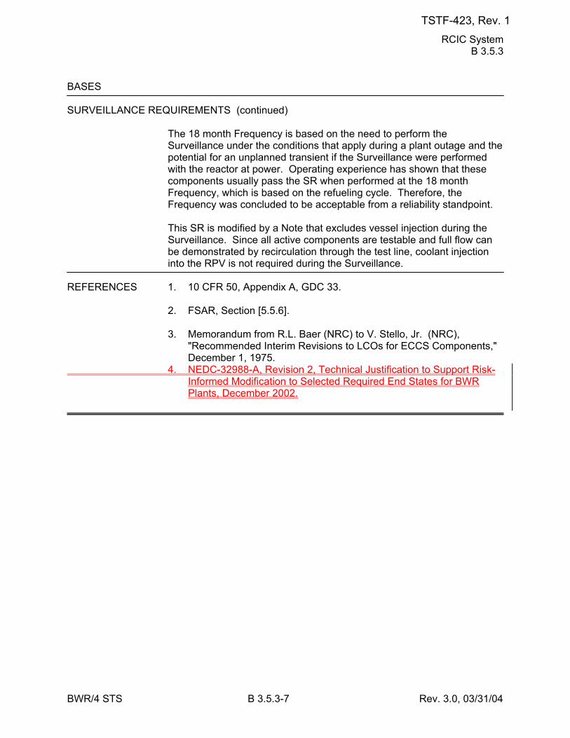
RCIC System B 3.5.3
BWR/4 STS B 3.5.3-7 Rev. 3.0, 03/31/04
BASES SURVEILLANCE REQUIREMENTS (continued)
The 18 month Frequency is based on the need to perform the Surveillance under the conditions that apply during a plant outage and the potential for an unplanned transient if the Surveillance were performed with the reactor at power. Operating experience has shown that these components usually pass the SR when performed at the 18 month Frequency, which is based on the refueling cycle. Therefore, the Frequency was concluded to be acceptable from a reliability standpoint. This SR is modified by a Note that excludes vessel injection during the Surveillance. Since all active components are testable and full flow can be demonstrated by recirculation through the test line, coolant injection into the RPV is not required during the Surveillance.
REFERENCES 1. 10 CFR 50, Appendix A, GDC 33. 2. FSAR, Section [5.5.6]. 3. Memorandum from R.L. Baer (NRC) to V. Stello, Jr. (NRC),
"Recommended Interim Revisions to LCOs for ECCS Components," December 1, 1975.
4. NEDC-32988-A, Revision 2, Technical Justification to Support Risk-Informed Modification to Selected Required End States for BWR Plants, December 2002.
TSTF-423, Rev. 1
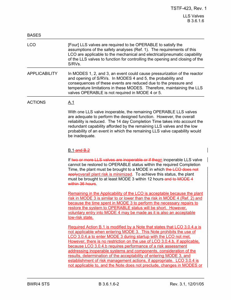
LLS Valves B 3.6.1.6
BWR/4 STS B 3.6.1.6-2 Rev. 3.1, 12/01/05
BASES LCO [Four] LLS valves are required to be OPERABLE to satisfy the
assumptions of the safety analyses (Ref. 1). The requirements of this LCO are applicable to the mechanical and electrical/pneumatic capability of the LLS valves to function for controlling the opening and closing of the S/RVs.
APPLICABILITY In MODES 1, 2, and 3, an event could cause pressurization of the reactor
and opening of S/RVs. In MODES 4 and 5, the probability and consequences of these events are reduced due to the pressure and temperature limitations in these MODES. Therefore, maintaining the LLS valves OPERABLE is not required in MODE 4 or 5.
ACTIONS A.1
With one LLS valve inoperable, the remaining OPERABLE LLS valves are adequate to perform the designed function. However, the overall reliability is reduced. The 14 day Completion Time takes into account the redundant capability afforded by the remaining LLS valves and the low probability of an event in which the remaining LLS valve capability would be inadequate. B.1 and B.2 If two or more LLS valves are inoperable or if thean inoperable LLS valve cannot be restored to OPERABLE status within the required Completion Time, the plant must be brought to a MODE in which the LCO does not applyoverall plant risk is minimized. To achieve this status, the plant must be brought to at least MODE 3 within 12 hours and to MODE 4 within 36 hours. Remaining in the Applicability of the LCO is acceptable because the plant risk in MODE 3 is similar to or lower than the risk in MODE 4 (Ref. 2) and because the time spent in MODE 3 to perform the necessary repairs to restore the system to OPERABLE status will be short. However, voluntary entry into MODE 4 may be made as it is also an acceptable low-risk state. Required Action B.1 is modified by a Note that states that LCO 3.0.4.a is not applicable when entering MODE 3. This Note prohibits the use of LCO 3.0.4.a to enter MODE 3 during startup with the LCO not met. However, there is no restriction on the use of LCO 3.0.4.b, if applicable, because LCO 3.0.4.b requires performance of a risk assessment addressing inoperable systems and components, consideration of the results, determination of the acceptability of entering MODE 3, and establishment of risk management actions, if appropriate. LCO 3.0.4 is not applicable to, and the Note does not preclude, changes in MODES or
TSTF-423, Rev. 1
LLS Valves B 3.6.1.6
BWR/4 STS B 3.6.1.6-3 Rev. 3.1, 12/01/05
other specified conditions in the Applicability that are required to comply with ACTIONS or that are part of a shutdown of the unit. The allowed Completion Times areis reasonable, based on operating experience, to reach the required plant conditions from full power conditions in an orderly manner and without challenging plant systems. C.1 and C,2 If two or more LLS valves are inoperable, there could be excessive short duration SIRV cycling during an overpressure event. The plant must be brought to a condition in which the LCO does not apply. To achieve this status, the plant must be brought to at least MODE 3 within 12 hours and MODE 4 within 36 hours. The allowed Completion Times are reasonable, based on operating experience, to reach the required plant conditions from full power conditions in an orderly manner and without challenging plant systems.
SURVEILLANCE SR 3.6.1.6.1 REQUIREMENTS
A manual actuation of each LLS valve is performed to verify that the valve and solenoids are functioning properly and no blockage exists in the valve discharge line. This can be demonstrated by the response of the turbine control or bypass valve, by a change in the measured steam flow, or by any other method that is suitable to verify steam flow. Adequate reactor steam dome pressure must be available to perform this test to avoid damaging the valve. Adequate pressure at which this test is to be performed is ≥ [920] psig (the pressure recommended by the valve
TSTF-423, Rev. 1
LLS Valves B 3.6.1.6
BWR/4 STS B 3.6.1.6-4 Rev. 3.1, 12/01/05
BASES SURVEILLANCE REQUIREMENTS (continued)
manufacturer). Also, adequate steam flow must be passing through the main turbine or turbine bypass valves to continue to control reactor pressure when the LLS valves divert steam flow upon opening. Adequate steam flow is represented by [at least 1.25 turbine bypass valves open, or total steam flow ≥ 106 lb/hr]. The [18] month Frequency was based on the S/RV tests required by the ASME Boiler and Pressure Vessel Code (Ref. 23). The Frequency of 18 months on a STAGGERED TEST BASIS ensures that each solenoid for each S/RV is alternately tested. Operating experience has shown that these components usually pass the Surveillance when performed at the [18] month Frequency. Therefore, the Frequency was concluded to be acceptable from a reliability standpoint. Since steam pressure is required to perform the Surveillance, however, and steam may not be available during a unit outage, the Surveillance may be performed during the startup following a unit outage. Unit startup is allowed prior to performing the test because valve OPERABILITY and the setpoints for overpressure protection are verified by Reference 2 3 prior to valve installation. After adequate reactor steam dome pressure and flow are reached, 12 hours is allowed to prepare for and perform the test. SR 3.6.1.6.2 The LLS designated S/RVs are required to actuate automatically upon receipt of specific initiation signals. A system functional test is performed to verify that the mechanical portions (i.e., solenoids) of the LLS function operate as designed when initiated either by an actual or simulated automatic initiation signal. The LOGIC SYSTEM FUNCTIONAL TEST in SR 3.3.6.3.7 overlaps this SR to provide complete testing of the safety function. The 18 month Frequency is based on the need to perform this Surveillance under the conditions that apply during a plant outage and the potential for an unplanned transient if the Surveillance were performed with the reactor at power. Operating experience has shown these components usually pass the Surveillance when performed at the 18 month Frequency. Therefore, the Frequency was concluded to be acceptable from a reliability standpoint. This SR is modified by a Note that excludes valve actuation. This prevents a reactor pressure vessel pressure blowdown.
TSTF-423, Rev. 1
LLS Valves B 3.6.1.6
BWR/4 STS B 3.6.1.6-5 Rev. 3.1, 12/01/05
BASES REFERENCES 1. FSAR, Section [5.5.17]. 2. NEDC-32988-A, Revision 2, Technical Justification to Support Risk-
Informed Modification to Selected Required End States for BWR Plants, December 2002.
23. ASME Code for Operation and Maintenance of Nuclear Power
Plants.
TSTF-423, Rev. 1
Reactor Building-to-Suppression Chamber Vacuum Breakers B 3.6.1.7
BWR/4 STS B 3.6.1.7-4 Rev. 3.0, 03/31/04
BASES ACTIONS (continued)
consistent with requirements for inoperable suppression-chamber-to- drywell vacuum breakers in LCO 3.6.1.8, "Suppression-Chamber-to- Drywell Vacuum Breakers." The 72 hour Completion Time takes into account the redundancy capability afforded by the remaining breakers, the fact that the OPERABLE breaker in each of the lines is closed, and the low probability of an event occurring that would require the vacuum breakers to be OPERABLE during this period. B.1 With one or more lines with two vacuum breakers not closed, primary containment integrity is not maintained. Therefore, one open vacuum breaker must be closed within 1 hour. This Completion Time is consistent with the ACTIONS of LCO 3.6.1.1, "Primary Containment," which requires that primary containment be restored to OPERABLE status within 1 hour. C.1 With one line with one or more vacuum breakers inoperable for opening, the leak tight primary containment boundary is intact. The ability to mitigate an event that causes a containment depressurization is threatened, however, if both vacuum breakers in at least one vacuum breaker penetration are not OPERABLE. Therefore, the inoperable vacuum breaker must be restored to OPERABLE status within 72 hours. This is consistent with the Completion Time for Condition A and the fact that the leak tight primary containment boundary is being maintained. D.1 If one line has one or more reactor building-to-suppression chamber vacuum breakers inoperable for opening and they are not restored within the Completion Time in Condition C, the remaining breakers in the remaining lines can provide the opening function. The plant must be brought to a condition in which overall plant risk is minimized. To achieve this status, the plant must be brought to at least MODE 3 within 12 hours. Remaining in the Applicability of the LCO is acceptable because the plant risk in MODE 3 is similar to or lower than the risk in MODE 4 (Ref. 2) and because the time spent in MODE 3 to perform the necessary repairs to restore the system to OPERABLE status will be short. However, voluntary entry into MODE 4 may be made as it is also an acceptable low-risk state.
TSTF-423, Rev. 1
Reactor Building-to-Suppression Chamber Vacuum Breakers B 3.6.1.7
BWR/4 STS B 3.6.1.7-5 Rev. 3.0, 03/31/04
Required Action D.1 is modified by a Note that states that LCO 3.0.4.a is not applicable when entering MODE 3. This Note prohibits the use of LCO 3.0.4.a to enter MODE 3 during startup with the LCO not met. However, there is no restriction on the use of LCO 3.0.4.b, if applicable, because LCO 3.0.4.b requires performance of a risk assessment addressing inoperable systems and components, consideration of the results, determination of the acceptability of entering MODE 3, and establishment of risk management actions, if appropriate. LCO 3.0.4 is not applicable to, and the Note does not preclude, changes in MODES or other specified conditions in the Applicability that are required to comply with ACTIONS or that are part of a shutdown of the unit. The allowed Completion Time is reasonable, based on operating experience, to reach the required plant conditions from full power conditions in an orderly manner and without challenging plant systems. DE.1 With two [or more] lines with one or more vacuum breakers inoperable for opening, the primary containment boundary is intact. However, in the event of a containment depressurization, the function of the vacuum breakers is lost. Therefore, all vacuum breakers in [one] line must be restored to OPERABLE status within 1 hour. This Completion Time is consistent with the ACTIONS of LCO 3.6.1.1, which requires that primary containment be restored to OPERABLE status within 1 hour.
TSTF-423, Rev. 1

Reactor Building-to-Suppression Chamber Vacuum Breakers B 3.6.1.7
BWR/4 STS B 3.6.1.7-6 Rev. 3.0, 03/31/04
BASES ACTIONS (continued)
EF.1 and EF.2 If all the vacuum breakers in [one] or more lines cannot be closed or restored to OPERABLE status within the required Completion Time, the plant must be brought to a MODE in which the LCO does not apply. To achieve this status, the plant must be brought to at least MODE 3 within 12 hours and to MODE 4 within 36 hours. The allowed Completion Times are reasonable, based on operating experience, to reach the required plant conditions from full power conditions in an orderly manner and without challenging plant systems.
SURVEILLANCE SR 3.6.1.7.1 REQUIREMENTS
Each vacuum breaker is verified to be closed to ensure that a potential breach in the primary containment boundary is not present. This Surveillance is performed by observing local or control room indications of vacuum breaker position or by verifying a differential pressure of [0.5] psid is maintained between the reactor building and suppression chamber. The 14 day Frequency is based on engineering judgment, is considered adequate in view of other indications of vacuum breaker status available to operations personnel, and has been shown to be acceptable through operating experience. Two Notes are added to this SR. The first Note allows reactor-to-suppression chamber vacuum breakers opened in conjunction with the performance of a Surveillance to not be considered as failing this SR. These periods of opening vacuum breakers are controlled by plant procedures and do not represent inoperable vacuum breakers. The second Note is included to clarify that vacuum breakers open due to an actual differential pressure are not considered as failing this SR. SR 3.6.1.7.2 Each vacuum breaker must be cycled to ensure that it opens properly to perform its design function and returns to its fully closed position. This ensures that the safety analysis assumptions are valid. The [92] day Frequency of this SR was developed based upon Inservice Testing Program requirements to perform valve testing at least once every [92] days.
TSTF-423, Rev. 1
Reactor Building-to-Suppression Chamber Vacuum Breakers B 3.6.1.7
BWR/4 STS B 3.6.1.7-7 Rev. 3.0, 03/31/04
BASES SURVEILLANCE REQUIREMENTS (continued)
SR 3.6.1.7.3 Demonstration of vacuum breaker opening setpoint is necessary to ensure that the safety analysis assumption regarding vacuum breaker full open differential pressure of ≤ [0.5] psid is valid. The [18] month Frequency is based on the need to perform this Surveillance under the conditions that apply during a plant outage and the potential for an unplanned transient if the Surveillance were performed with the reactor at power. For this unit, the [18] month Frequency has been shown to be acceptable, based on operating experience, and is further justified because of other surveillances performed at shorter Frequencies that convey the proper functioning status of each vacuum breaker.
REFERENCES 1. FSAR, Section [6.2]. 2. NEDC-32988-A, Revision 2, Technical Justification to Support Risk-
Informed Modification to Selected Required End States for BWR Plants, December 2002.
TSTF-423, Rev. 1
Suppression Chamber-to-Drywell Vacuum Breakers B 3.6.1.8
BWR/4 STS B 3.6.1.8-3 Rev. 3.0, 03/31/04
BASES APPLICABILITY (continued)
Also, in MODES 1, 2, and 3, a DBA could result in excessive negative differential pressure across the drywell wall, caused by the rapid depressurization of the drywell. The event that results in the limiting rapid depressurization of the drywell is the primary system rupture that purges the drywell of air and fills the drywell free airspace with steam. Subsequent condensation of the steam would result in depressurization of the drywell. The limiting pressure and temperature of the primary system prior to a DBA occur in MODES 1, 2, and 3. In MODES 4 and 5, the probability and consequences of these events are reduced by the pressure and temperature limitations in these MODES; therefore, maintaining suppression chamber-to-drywell vacuum breakers OPERABLE is not required in MODE 4 or 5.
ACTIONS A.1
With one of the required vacuum breakers inoperable for opening (e.g., the vacuum breaker is not open and may be stuck closed or not within its opening setpoint limit, so that it would not function as designed during an event that depressurized the drywell), the remaining [eight] OPERABLE vacuum breakers are capable of providing the vacuum relief function. However, overall system reliability is reduced because a single failure in one of the remaining vacuum breakers could result in an excessive suppression chamber-to-drywell differential pressure during a DBA. Therefore, with one of the [nine] required vacuum breakers inoperable, 72 hours is allowed to restore at least one of the inoperable vacuum breakers to OPERABLE status so that plant conditions are consistent with those assumed for the design basis analysis. The 72 hour Completion Time is considered acceptable due to the low probability of an event in which the remaining vacuum breaker capability would not be adequate. B.1 If a required suppression chamber-to-drywell vacuum breaker is inoperable for opening and is not restored to OPERABLE status within the required Completion Time, the plant must be brought to a condition in which overall plant risk is minimized. To achieve this status, the plant must be brought to at least MODE 3 within 12 hours. Remaining in the Applicability of the LCO is acceptable because the plant risk in MODE 3 is similar to or lower than the risk in MODE 4 (Ref. 2) and because the time spent in MODE 3 to perform the necessary repairs to restore the system to OPERABLE status will be short. However, voluntary entry into MODE 4 may be made as it is also an acceptable low-risk state.
TSTF-423, Rev. 1
Suppression Chamber-to-Drywell Vacuum Breakers B 3.6.1.8
BWR/4 STS B 3.6.1.8-4 Rev. 3.0, 03/31/04
Required Action B.1 is modified by a Note that states that LCO 3.0.4.a is not applicable when entering MODE 3. This Note prohibits the use of LCO 3.0.4.a to enter MODE 3 during startup with the LCO not met. However, there is no restriction on the use of LCO 3.0.4.b, if applicable, because LCO 3.0.4.b requires performance of a risk assessment addressing inoperable systems and components, consideration of the results, determination of the acceptability of entering MODE 3, and establishment of risk management actions, if appropriate. LCO 3.0.4 is not applicable to, and the Note does not preclude, changes in MODES or other specified conditions in the Applicability that are required to comply with ACTIONS or that are part of a shutdown of the unit. The allowed Completion Time is reasonable, based on operating experience, to reach the required plant conditions from full power conditions in an orderly manner and without challenging plant systems. BC.1 An open vacuum breaker allows communication between the drywell and suppression chamber airspace, and, as a result, there is the potential for suppression chamber overpressurization due to this bypass leakage if a LOCA were to occur. Therefore, the open vacuum breaker must be closed. A short time is allowed to close the vacuum breaker due to the low probability of an event that would pressurize primary containment. If vacuum breaker position indication is not reliable, an alternate method of verifying that the vacuum breakers are closed is to verify that a differential pressure of [0.5] psid between the suppression chamber and drywell is maintained for 1 hour without makeup. The required 2 hour Completion Time is considered adequate to perform this test.
TSTF-423, Rev. 1
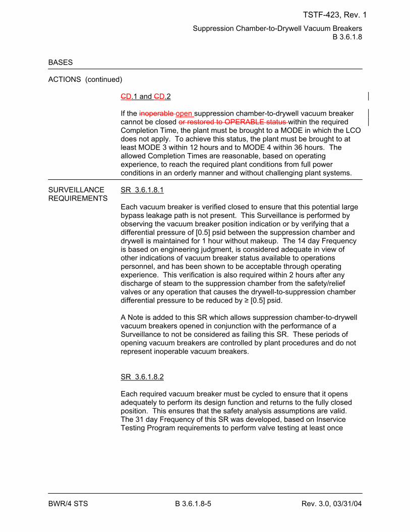
Suppression Chamber-to-Drywell Vacuum Breakers B 3.6.1.8
BWR/4 STS B 3.6.1.8-5 Rev. 3.0, 03/31/04
BASES ACTIONS (continued)
CD.1 and CD.2 If the inoperable open suppression chamber-to-drywell vacuum breaker cannot be closed or restored to OPERABLE status within the required Completion Time, the plant must be brought to a MODE in which the LCO does not apply. To achieve this status, the plant must be brought to at least MODE 3 within 12 hours and to MODE 4 within 36 hours. The allowed Completion Times are reasonable, based on operating experience, to reach the required plant conditions from full power conditions in an orderly manner and without challenging plant systems.
SURVEILLANCE SR 3.6.1.8.1 REQUIREMENTS
Each vacuum breaker is verified closed to ensure that this potential large bypass leakage path is not present. This Surveillance is performed by observing the vacuum breaker position indication or by verifying that a differential pressure of [0.5] psid between the suppression chamber and drywell is maintained for 1 hour without makeup. The 14 day Frequency is based on engineering judgment, is considered adequate in view of other indications of vacuum breaker status available to operations personnel, and has been shown to be acceptable through operating experience. This verification is also required within 2 hours after any discharge of steam to the suppression chamber from the safety/relief valves or any operation that causes the drywell-to-suppression chamber differential pressure to be reduced by ≥ [0.5] psid. A Note is added to this SR which allows suppression chamber-to-drywell vacuum breakers opened in conjunction with the performance of a Surveillance to not be considered as failing this SR. These periods of opening vacuum breakers are controlled by plant procedures and do not represent inoperable vacuum breakers. SR 3.6.1.8.2 Each required vacuum breaker must be cycled to ensure that it opens adequately to perform its design function and returns to the fully closed position. This ensures that the safety analysis assumptions are valid. The 31 day Frequency of this SR was developed, based on Inservice Testing Program requirements to perform valve testing at least once
TSTF-423, Rev. 1
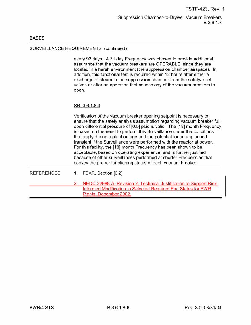
Suppression Chamber-to-Drywell Vacuum Breakers B 3.6.1.8
BWR/4 STS B 3.6.1.8-6 Rev. 3.0, 03/31/04
BASES SURVEILLANCE REQUIREMENTS (continued)
every 92 days. A 31 day Frequency was chosen to provide additional assurance that the vacuum breakers are OPERABLE, since they are located in a harsh environment (the suppression chamber airspace). In addition, this functional test is required within 12 hours after either a discharge of steam to the suppression chamber from the safety/relief valves or after an operation that causes any of the vacuum breakers to open. SR 3.6.1.8.3 Verification of the vacuum breaker opening setpoint is necessary to ensure that the safety analysis assumption regarding vacuum breaker full open differential pressure of [0.5] psid is valid. The [18] month Frequency is based on the need to perform this Surveillance under the conditions that apply during a plant outage and the potential for an unplanned transient if the Surveillance were performed with the reactor at power. For this facility, the [18] month Frequency has been shown to be acceptable, based on operating experience, and is further justified because of other surveillances performed at shorter Frequencies that convey the proper functioning status of each vacuum breaker.
REFERENCES 1. FSAR, Section [6.2]. 2. NEDC-32988-A, Revision 2, Technical Justification to Support Risk-
Informed Modification to Selected Required End States for BWR Plants, December 2002.
TSTF-423, Rev. 1

MSIV LCS B 3.6.1.9
BWR/4 STS B 3.6.1.9-2 Rev. 3.0, 03/31/04
BASES APPLICABILITY In MODES 1, 2, and 3, a DBA could lead to a fission product release to
primary containment. Therefore, MSIV LCS OPERABILITY is required during these MODES. In MODES 4 and 5, the probability and consequences of these events are reduced due to the pressure and temperature limitations in these MODES. Therefore, maintaining the MSIV LCS OPERABLE is not required in MODE 4 or 5 to ensure MSIV leakage is processed.
ACTIONS A.1
With one MSIV LCS subsystem inoperable, the inoperable MSIV LCS subsystem must be restored to OPERABLE status within 30 days. In this Condition, the remaining OPERABLE MSIV LCS subsystem is adequate to perform the required leakage control function. However, the overall reliability is reduced because a single failure in the remaining subsystem could result in a total loss of MSIV leakage control function. The 30 day Completion Time is based on the redundant capability afforded by the remaining OPERABLE MSIV LCS subsystem and the low probability of a DBA LOCA occurring during this period. B.1 With two MSIV LCS subsystems inoperable, at least one subsystem must be restored to OPERABLE status within 7 days. The 7 day Completion Time is based on the low probability of the occurrence of a DBA LOCA. C.1 and C.2 If the MSIV LCS subsystem cannot be restored to OPERABLE status within the required Completion Time, the plant must be brought to a MODE in which the LCO does not applyoverall plant risk is minimized. To achieve this status, the plant must be brought to at least MODE 3 within 12 hours and to MODE 4 within 36 hours. Remaining in the Applicability of the LCO is acceptable because the plant risk in MODE 3 is similar to or lower than the risk in MODE 4 (Ref. 3) and because the time spent in MODE 3 to perform the necessary repairs to restore the system to OPERABLE status will be short. However, voluntary entry into MODE 4 may be made as it is also an acceptable low-risk state. Required Action C.1 is modified by a Note that states that LCO 3.0.4.a is not applicable when entering MODE 3. This Note prohibits the use of LCO 3.0.4.a to enter MODE 3 during startup with the LCO not met. However, there is no restriction on the use of LCO 3.0.4.b, if applicable, because LCO 3.0.4.b requires performance of a risk assessment
TSTF-423, Rev. 1
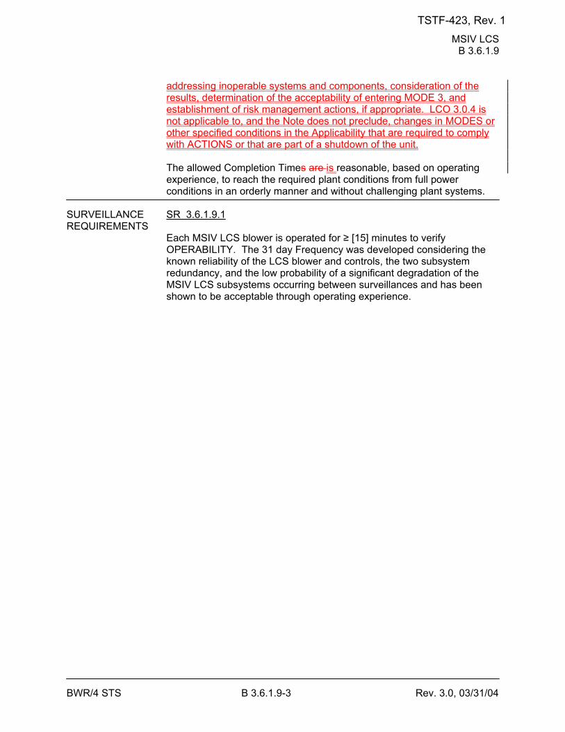
MSIV LCS B 3.6.1.9
BWR/4 STS B 3.6.1.9-3 Rev. 3.0, 03/31/04
addressing inoperable systems and components, consideration of the results, determination of the acceptability of entering MODE 3, and establishment of risk management actions, if appropriate. LCO 3.0.4 is not applicable to, and the Note does not preclude, changes in MODES or other specified conditions in the Applicability that are required to comply with ACTIONS or that are part of a shutdown of the unit. The allowed Completion Times are is reasonable, based on operating experience, to reach the required plant conditions from full power conditions in an orderly manner and without challenging plant systems.
SURVEILLANCE SR 3.6.1.9.1 REQUIREMENTS
Each MSIV LCS blower is operated for ≥ [15] minutes to verify OPERABILITY. The 31 day Frequency was developed considering the known reliability of the LCS blower and controls, the two subsystem redundancy, and the low probability of a significant degradation of the MSIV LCS subsystems occurring between surveillances and has been shown to be acceptable through operating experience.
TSTF-423, Rev. 1
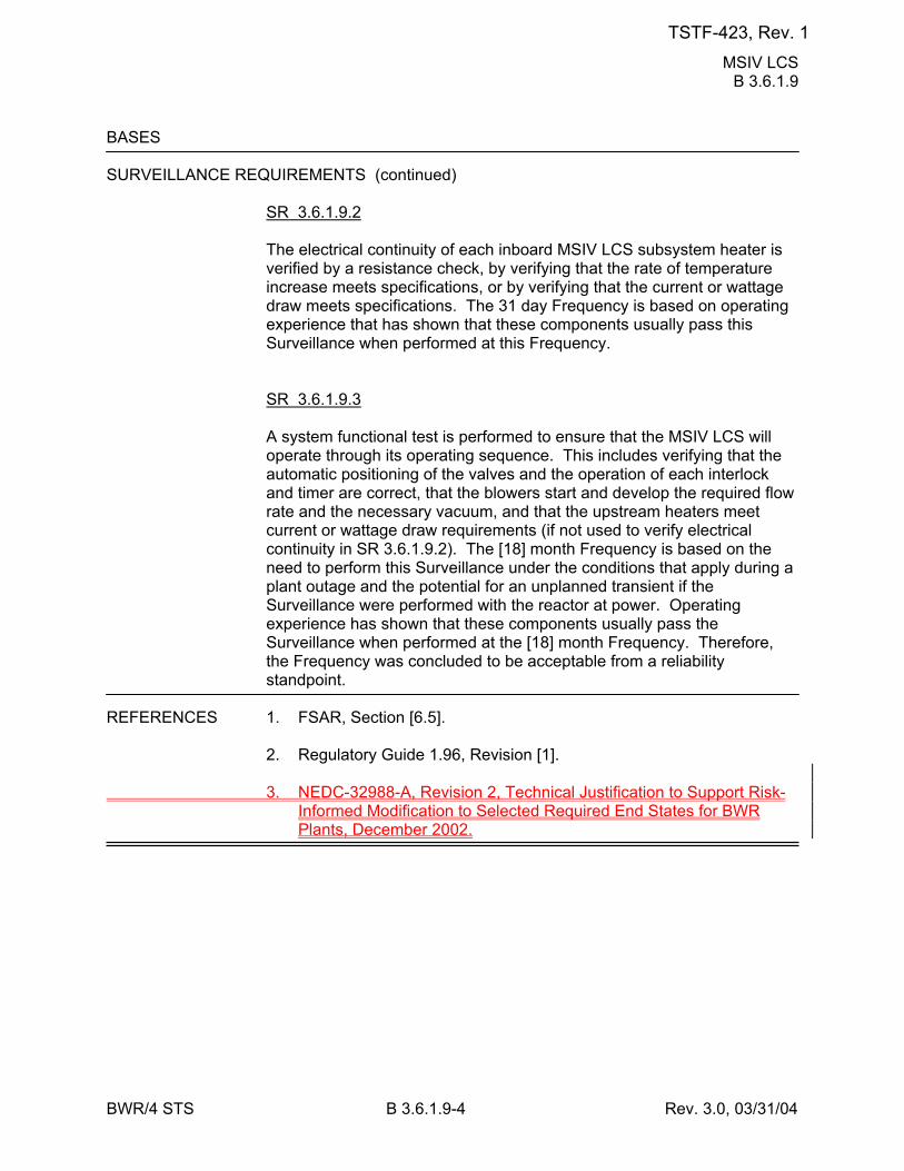
MSIV LCS B 3.6.1.9
BWR/4 STS B 3.6.1.9-4 Rev. 3.0, 03/31/04
BASES SURVEILLANCE REQUIREMENTS (continued)
SR 3.6.1.9.2 The electrical continuity of each inboard MSIV LCS subsystem heater is verified by a resistance check, by verifying that the rate of temperature increase meets specifications, or by verifying that the current or wattage draw meets specifications. The 31 day Frequency is based on operating experience that has shown that these components usually pass this Surveillance when performed at this Frequency. SR 3.6.1.9.3 A system functional test is performed to ensure that the MSIV LCS will operate through its operating sequence. This includes verifying that the automatic positioning of the valves and the operation of each interlock and timer are correct, that the blowers start and develop the required flow rate and the necessary vacuum, and that the upstream heaters meet current or wattage draw requirements (if not used to verify electrical continuity in SR 3.6.1.9.2). The [18] month Frequency is based on the need to perform this Surveillance under the conditions that apply during a plant outage and the potential for an unplanned transient if the Surveillance were performed with the reactor at power. Operating experience has shown that these components usually pass the Surveillance when performed at the [18] month Frequency. Therefore, the Frequency was concluded to be acceptable from a reliability standpoint.
REFERENCES 1. FSAR, Section [6.5]. 2. Regulatory Guide 1.96, Revision [1]. 3. NEDC-32988-A, Revision 2, Technical Justification to Support Risk-
Informed Modification to Selected Required End States for BWR Plants, December 2002.
TSTF-423, Rev. 1

RHR Suppression Pool Cooling B 3.6.2.3
BWR/4 STS B 3.6.2.3-2 Rev. 3.1, 12/01/05
BASES LCO During a DBA, a minimum of one RHR suppression pool cooling
subsystem is required to maintain the primary containment peak pressure and temperature below design limits (Ref. 1). To ensure that these requirements are met, two RHR suppression pool cooling subsystems must be OPERABLE with power from two safety related independent power supplies. Therefore, in the event of an accident, at least one subsystem is OPERABLE assuming the worst case single active failure. An RHR suppression pool cooling subsystem is OPERABLE when one of the pumps, the heat exchanger, and associated piping, valves, instrumentation, and controls are OPERABLE.
APPLICABILITY In MODES 1, 2, and 3, a DBA could cause a release of radioactive
material to primary containment and cause a heatup and pressurization of primary containment. In MODES 4 and 5, the probability and consequences of these events are reduced due to the pressure and temperature limitations in these MODES. Therefore, the RHR Suppression Pool Cooling System is not required to be OPERABLE in MODE 4 or 5.
ACTIONS A.1
With one RHR suppression pool cooling subsystem inoperable, the inoperable subsystem must be restored to OPERABLE status within 7 days. In this Condition, the remaining RHR suppression pool cooling subsystem is adequate to perform the primary containment cooling function. However, the overall reliability is reduced because a single failure in the OPERABLE subsystem could result in reduced primary containment cooling capability. The 7 day Completion Time is acceptable in light of the redundant RHR suppression pool cooling capabilities afforded by the OPERABLE subsystem and the low probability of a DBA occurring during this period. B.1 If one RHR suppression pool cooling subsystem is inoperable and is not restored to OPERABLE status within the required Completion Time, the plant must be brought to a condition in which overall plant risk is minimized. To achieve this status, the plant must be brought to at least MODE 3 within 12 hours. Remaining in the Applicability of the LCO is acceptable because the plant risk in MODE 3 is similar to or lower than the risk in MODE 4 (Ref. 2) and because the time spent in MODE 3 to perform the necessary repairs to restore the system to OPERABLE status will be short. However, voluntary entry into MODE 4 may be made as it is also an acceptable low-risk state.
TSTF-423, Rev. 1
RHR Suppression Pool Cooling B 3.6.2.3
BWR/4 STS B 3.6.2.3-3 Rev. 3.1, 12/01/05
Required Action B.1 is modified by a Note that states that LCO 3.0.4.a is not applicable when entering MODE 3. This Note prohibits the use of LCO 3.0.4.a to enter MODE 3 during startup with the LCO not met. However, there is no restriction on the use of LCO 3.0.4.b, if applicable, because LCO 3.0.4.b requires performance of a risk assessment addressing inoperable systems and components, consideration of the results, determination of the acceptability of entering MODE 3, and establishment of risk management actions, if appropriate. LCO 3.0.4 is not applicable to, and the Note does not preclude, changes in MODES or other specified conditions in the Applicability that are required to comply with ACTIONS or that are part of a shutdown of the unit. The allowed Completion Time is reasonable, based on operating experience, to reach the required plant conditions from full power conditions in an orderly manner and without challenging plant systems. BC.1 With two RHR suppression pool cooling subsystems inoperable, one subsystem must be restored to OPERABLE status within 8 hours. In this condition, there is a substantial loss of the primary containment pressure and temperature mitigation function. The 8 hour Completion Time is based on this loss of function and is considered acceptable due to the low probability of a DBA and the potential avoidance of a plant shutdown transient that could result in the need for the RHR suppression pool cooling subsystems to operate.
TSTF-423, Rev. 1
RHR Suppression Pool Cooling B 3.6.2.3
BWR/4 STS B 3.6.2.3-4 Rev. 3.1, 12/01/05
BASES ACTIONS (continued)
CD.1 and CD.2 If the Required Action and associated Completion Time of Condition C cannot be met, the plant must be brought to a MODE in which the LCO does not apply. To achieve this status, the plant must be brought to at least MODE 3 within 12 hours and to MODE 4 within 36 hours. The allowed Completion Times are reasonable, based on operating experience, to reach the required plant conditions from full power conditions in an orderly manner and without challenging plant systems.
SURVEILLANCE SR 3.6.2.3.1 REQUIREMENTS
Verifying the correct alignment for manual, power operated, and automatic valves in the RHR suppression pool cooling mode flow path provides assurance that the proper flow path exists for system operation. This SR does not apply to valves that are locked, sealed, or otherwise secured in position since these valves were verified to be in the correct position prior to locking, sealing, or securing. A valve is also allowed to be in the nonaccident position provided it can be aligned to the accident position within the time assumed in the accident analysis. This is acceptable since the RHR suppression pool cooling mode is manually initiated. This SR does not require any testing or valve manipulation; rather, it involves verification that those valves capable of being mispositioned are in the correct position. This SR does not apply to valves that cannot be inadvertently misaligned, such as check valves. The Frequency of 31 days is justified because the valves are operated under procedural control, improper valve position would affect only a single subsystem, the probability of an event requiring initiation of the system is low, and the subsystem is a manually initiated system. This Frequency has been shown to be acceptable based on operating experience. SR 3.6.2.3.2 Verifying that each RHR pump develops a flow rate ≥ [7700] gpm while operating in the suppression pool cooling mode with flow through the associated heat exchanger ensures that pump performance has not degraded during the cycle. Flow is a normal test of centrifugal pump performance required by ASME Code (Ref. 23). This test confirms one point on the pump design curve, and the results are indicative of overall performance. Such inservice inspections confirm component OPERABILITY, trend performance, and detect incipient failures by indicating abnormal performance. The Frequency of this SR is [in accordance with the Inservice Testing Program or 92 days].
TSTF-423, Rev. 1

RHR Suppression Pool Cooling B 3.6.2.3
BWR/4 STS B 3.6.2.3-5 Rev. 3.1, 12/01/05
BASES REFERENCES 1. FSAR, Section [6.2]. 2. NEDC-32988-A, Revision 2, Technical Justification to Support Risk-
Informed Modification to Selected Required End States for BWR Plants, December 2002.
23. ASME Code for Operation and Maintenance of Nuclear Power
Plants.
TSTF-423, Rev. 1
RHR Suppression Pool Spray B 3.6.2.4
BWR/4 STS B 3.6.2.4-3 Rev. 3.1, 12/01/05
BASES ACTIONS (continued)
C.1 and C.2 If the inoperable RHR suppression pool spray subsystem cannot be restored to OPERABLE status within the associated Completion Time, the plant must be brought to a MODE in which the LCO does not applyoverall plant risk is minimized. To achieve this status, the plant must be brought to at least MODE 3 within 12 hours and MODE 4 within 36 hours. Remaining in the Applicability of the LCO is acceptable because the plant risk in MODE 3 is similar to or lower than the risk in MODE 4 (Ref. 2) and because the time spent in MODE 3 to perform the necessary repairs to restore the system to OPERABLE status will be short. However, voluntary entry into MODE 4 may be made as it is also an acceptable low-risk state. Required Action C.1 is modified by a Note that states that LCO 3.0.4.a is not applicable when entering MODE 3. This Note prohibits the use of LCO 3.0.4.a to enter MODE 3 during startup with the LCO not met. However, there is no restriction on the use of LCO 3.0.4.b, if applicable, because LCO 3.0.4.b requires performance of a risk assessment addressing inoperable systems and components, consideration of the results, determination of the acceptability of entering MODE 3, and establishment of risk management actions, if appropriate. LCO 3.0.4 is not applicable to, and the Note does not preclude, changes in MODES or other specified conditions in the Applicability that are required to comply with ACTIONS or that are part of a shutdown of the unit. The allowed Completion Times are is reasonable, based on operating experience, to reach the required plant conditions from full power conditions in an orderly manner and without challenging plant systems.
SURVEILLANCE SR 3.6.2.4.1 REQUIREMENTS
Verifying the correct alignment for manual, power operated, and automatic valves in the RHR suppression pool spray mode flow path provides assurance that the proper flow paths will exist for system operation. This SR does not apply to valves that are locked, sealed, or otherwise secured in position since these valves were verified to be in the correct position prior to locking, sealing, or securing. A valve is also allowed to be in the nonaccident position provided it can be aligned to the accident position within the time assumed in the accident analysis. This is acceptable since the RHR suppression pool cooling mode is manually initiated. This SR does not require any testing or valve manipulation; rather, it involves verification that those valves capable of being
TSTF-423, Rev. 1
RHR Suppression Pool Spray B 3.6.2.4
BWR/4 STS B 3.6.2.4-4 Rev. 3.1, 12/01/05
mispositioned are in the correct position. This SR does not apply to valves that cannot be inadvertently misaligned, such as check valves. The Frequency of 31 days is justified because the valves are operated under procedural control, improper valve position would affect only a single subsystem, the probability of an event requiring initiation of the system is low, and the subsystem is a manually initiated system. This Frequency has been shown to be acceptable based on operating experience. SR 3.6.2.4.2 Verifying each RHR pump develops a flow rate ≥ [400] gpm while operating in the suppression pool spray mode with flow through the heat exchanger ensures that pump performance has not degraded during the cycle. Flow is a normal test of centrifugal pump performance required by the ASME Code (Ref. 23). This test confirms one point on the pump design curve and is indicative of overall performance. Such inservice
TSTF-423, Rev. 1
RHR Suppression Pool Spray B 3.6.2.4
BWR/4 STS B 3.6.2.4-5 Rev. 3.1, 12/01/05
BASES SURVEILLANCE REQUIREMENTS (continued)
inspections confirm component OPERABILITY, trend performance, and detect incipient failures by indicating abnormal performance. The Frequency of this SR is [in accordance with the Inservice Testing Program, but the Frequency must not exceed 92 days].
REFERENCES 1. FSAR, Section [6.2]. 2. NEDC-32988-A, Revision 2, Technical Justification to Support Risk-
Informed Modification to Selected Required End States for BWR Plants, December 2002.
23. ASME Code for Operation and Maintenance of Nuclear Power
Plants.
TSTF-423, Rev. 1
[Secondary] Containment B 3.6.4.1
BWR/4 STS B 3.6.4.1-3 Rev. 3.0, 03/31/04
BASES APPLICABILITY (continued)
-During fuel handling/core alterations, ventilation system and radiation monitor availability (as defined in NUMARC 91-06) should be assessed, with respect to filtration and monitoring of releases from the fuel. Following shutdown, radioactivity in the fuel decays away fairly rapidly. The basis of the Technical Specification operability amendment is the reduction in doses due to such decay. The goal of maintaining ventilation system and radiation monitor availability is to reduce doses even further below that provided by the natural decay. -A single normal or contingency method to promptly close primary or secondary containment penetrations should be developed. Such prompt methods need not completely block the penetration or be capable of resisting pressure. The purpose of the "prompt methods" mentioned above are to enable ventilation systems to draw the release from a postulated fuel handling accident in the proper direction such that it can be treated and monitored." --------------------------------------------------------------------------------------------------
ACTIONS A.1
If [secondary] containment is inoperable, it must be restored to OPERABLE status within 4 hours. The 4 hour Completion Time provides a period of time to correct the problem that is commensurate with the importance of maintaining [secondary] containment during MODES 1, 2, and 3. This time period also ensures that the probability of an accident (requiring [secondary] containment OPERABILITY) occurring during periods where [secondary] containment is inoperable is minimal. B.1 and B.2 If [secondary] containment cannot be restored to OPERABLE status within the required Completion Time, the plant must be brought to a MODE in which the LCO does not applyoverall plant risk is minimized. To achieve this status, the plant must be brought to at least MODE 3 within 12 hours and to MODE 4 within 36 hours. Remaining in the Applicability of the LCO is acceptable because the plant risk in MODE 3 is similar to or lower than the risk in MODE 4 (Ref. 3), because the time spent in MODE 3 to perform the necessary repairs to restore the system to OPERABLE status will be short. However, voluntary entry into MODE 4 may be made as it is also an acceptable low-risk state.
TSTF-423, Rev. 1

[Secondary] Containment B 3.6.4.1
BWR/4 STS B 3.6.4.1-4 Rev. 3.0, 03/31/04
Required Action B.1 is modified by a Note that states that LCO 3.0.4.a is not applicable when entering MODE 3. This Note prohibits the use of LCO 3.0.4.a to enter MODE 3 during startup with the LCO not met. However, there is no restriction on the use of LCO 3.0.4.b, if applicable, because LCO 3.0.4.b requires performance of a risk assessment addressing inoperable systems and components, consideration of the results, determination of the acceptability of entering MODE 3, and establishment of risk management actions, if appropriate. LCO 3.0.4 is not applicable to, and the Note does not preclude, changes in MODES or other specified conditions in the Applicability that are required to comply with ACTIONS or that are part of a shutdown of the unit. The allowed Completion Times are is reasonable, based on operating experience, to reach the required plant conditions from full power conditions in an orderly manner and without challenging plant systems.
TSTF-423, Rev. 1
[Secondary] Containment B 3.6.4.1
BWR/4 STS B 3.6.4.1-7 Rev. 3.0, 03/31/04
BASES SURVEILLANCE REQUIREMENTS (continued)
SR 3.6.4.1.4, which demonstrates that the [secondary] containment can be drawn down to ≥ [0.25] inches of vacuum water gauge in ≤ [120] seconds using one SGT subsystem.] SR 3.6.4.1.5 demonstrates that the pressure in the [secondary] containment can be maintained ≥ [0.266] inches of vacuum water gauge for 1 hour using one SGT subsystem at a flow rate ≤ [4000] cfm. The 1 hour test period allows [secondary] containment to be in thermal equilibrium at steady state conditions. The primary purpose of these SR[s] is to ensure [secondary] containment boundary integrity. The secondary purpose of these SR[s] is to ensure that the SGT subsystem being tested functions as designed. There is a separate LCO with Surveillance Requirements which serves the primary purpose of ensuring OPERABILITY of the SGT System. These SR[s] need not be performed with each SGT subsystem. The SGT subsystem used for these Surveillance[s] is staggered to ensure that in addition to the requirements of LCO 3.6.4.3, either SGT subsystem will perform this test. The inoperability of the SGT System does not necessarily constitute a failure of these Surveillance[s] relative to the [secondary] containment OPERABILITY. Operating experience has shown the [secondary] containment boundary usually passes these Surveillance[s] when performed at the [18] month Frequency. Therefore, the Frequency was concluded to be acceptable from a reliability standpoint.
REFERENCES 1. FSAR, Section [15.1.39]. 2. FSAR, Section [15.1.41]. 3. NEDC-32988-A, Revision 2, Technical Justification to Support Risk-
Informed Modification to Selected Required End States for BWR Plants, December 2002.
TSTF-423, Rev. 1
SGT System B 3.6.4.3
BWR/4 STS B 3.6.4.3-3 Rev. 3.0, 03/31/04
BASES ACTIONS (continued)
subsystem could result in the radioactivity release control function not being adequately performed. The 7 day Completion Time is based on consideration of such factors as the availability of the OPERABLE redundant SGT System and the low probability of a DBA occurring during this period. B.1 and B.2 If the SGT subsystem cannot be restored to OPERABLE status within the required Completion Time in MODE 1, 2, or 3, the plant must be brought to a MODE in which the LCO does not applyoverall plant risk is minimized. To achieve this status, the plant must be brought to at least MODE 3 within 12 hours and to MODE 4 within 36 hours. Remaining in the Applicability of the LCO is acceptable because the plant risk in MODE 3 is similar to or lower than the risk in MODE 4 (Ref. 3) and because the time spent in MODE 3 to perform the necessary repairs to restore the system to OPERABLE status will be short. However, voluntary entry into MODE 4 may be made as it is also an acceptable low-risk state. Required Action B.1 is modified by a Note that states that LCO 3.0.4.a is not applicable when entering MODE 3. This Note prohibits the use of LCO 3.0.4.a to enter MODE 3 during startup with the LCO not met. However, there is no restriction on the use of LCO 3.0.4.b, if applicable, because LCO 3.0.4.b requires performance of a risk assessment addressing inoperable systems and components, consideration of the results, determination of the acceptability of entering MODE 3, and establishment of risk management actions, if appropriate. LCO 3.0.4 is not applicable to, and the Note does not preclude, changes in MODES or other specified conditions in the Applicability that are required to comply with ACTIONS or that are part of a shutdown of the unit. The allowed Completion Times are is reasonable, based on operating experience, to reach the required plant conditions from full power conditions in an orderly manner and without challenging plant systems. C.1, C.2.1, and C.2.2 During movement of [recently] irradiated fuel assemblies, in the [secondary] containment or during OPDRVs, when Required Action A.1 cannot be completed within the required Completion Time, the OPERABLE SGT subsystem should immediately be placed in operation. This action ensures that the remaining subsystem is OPERABLE, that no
TSTF-423, Rev. 1
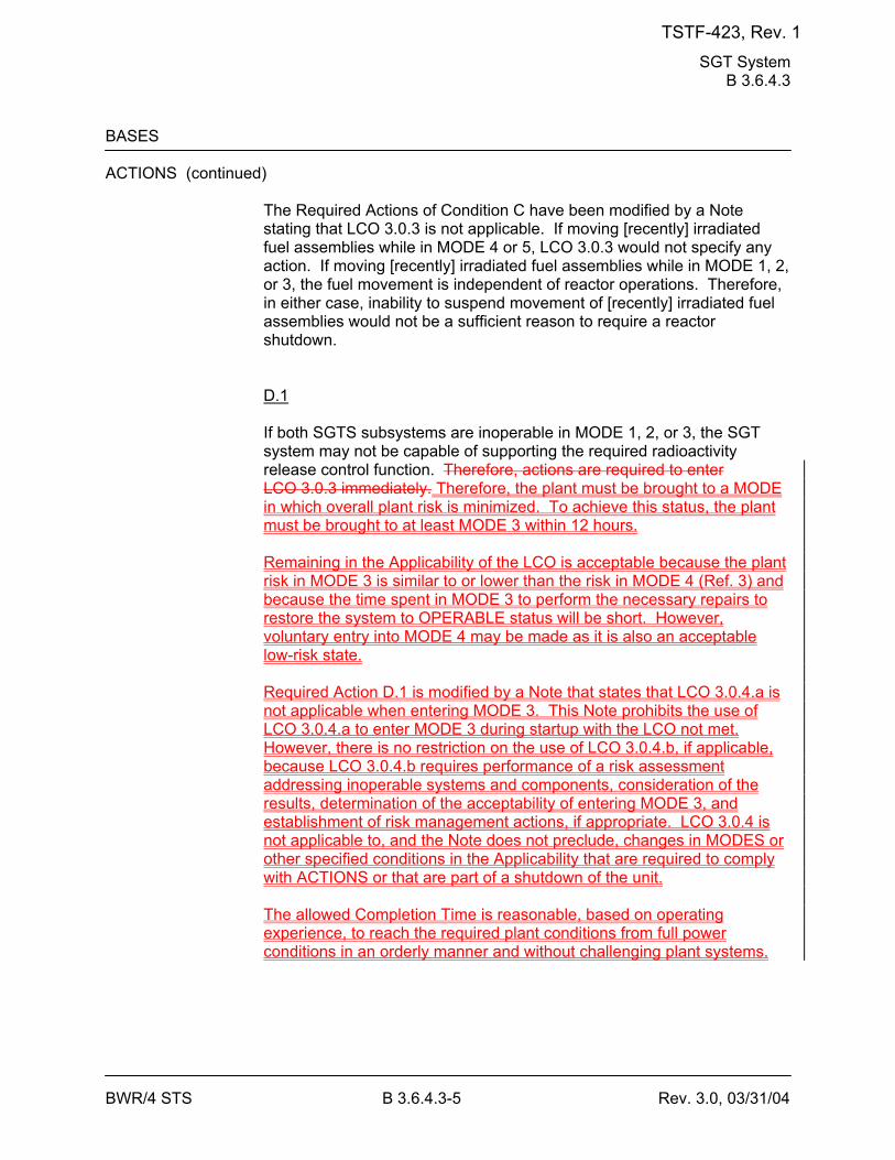
SGT System B 3.6.4.3
BWR/4 STS B 3.6.4.3-5 Rev. 3.0, 03/31/04
BASES ACTIONS (continued)
The Required Actions of Condition C have been modified by a Note stating that LCO 3.0.3 is not applicable. If moving [recently] irradiated fuel assemblies while in MODE 4 or 5, LCO 3.0.3 would not specify any action. If moving [recently] irradiated fuel assemblies while in MODE 1, 2, or 3, the fuel movement is independent of reactor operations. Therefore, in either case, inability to suspend movement of [recently] irradiated fuel assemblies would not be a sufficient reason to require a reactor shutdown. D.1 If both SGTS subsystems are inoperable in MODE 1, 2, or 3, the SGT system may not be capable of supporting the required radioactivity release control function. Therefore, actions are required to enter LCO 3.0.3 immediately. Therefore, the plant must be brought to a MODE in which overall plant risk is minimized. To achieve this status, the plant must be brought to at least MODE 3 within 12 hours. Remaining in the Applicability of the LCO is acceptable because the plant risk in MODE 3 is similar to or lower than the risk in MODE 4 (Ref. 3) and because the time spent in MODE 3 to perform the necessary repairs to restore the system to OPERABLE status will be short. However, voluntary entry into MODE 4 may be made as it is also an acceptable low-risk state. Required Action D.1 is modified by a Note that states that LCO 3.0.4.a is not applicable when entering MODE 3. This Note prohibits the use of LCO 3.0.4.a to enter MODE 3 during startup with the LCO not met. However, there is no restriction on the use of LCO 3.0.4.b, if applicable, because LCO 3.0.4.b requires performance of a risk assessment addressing inoperable systems and components, consideration of the results, determination of the acceptability of entering MODE 3, and establishment of risk management actions, if appropriate. LCO 3.0.4 is not applicable to, and the Note does not preclude, changes in MODES or other specified conditions in the Applicability that are required to comply with ACTIONS or that are part of a shutdown of the unit. The allowed Completion Time is reasonable, based on operating experience, to reach the required plant conditions from full power conditions in an orderly manner and without challenging plant systems.
TSTF-423, Rev. 1
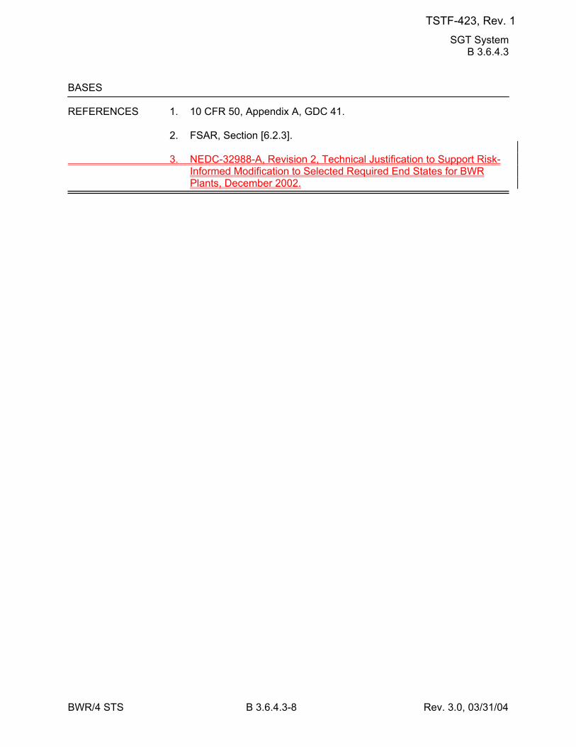
SGT System B 3.6.4.3
BWR/4 STS B 3.6.4.3-8 Rev. 3.0, 03/31/04
BASES REFERENCES 1. 10 CFR 50, Appendix A, GDC 41. 2. FSAR, Section [6.2.3]. 3. NEDC-32988-A, Revision 2, Technical Justification to Support Risk-
Informed Modification to Selected Required End States for BWR Plants, December 2002.
TSTF-423, Rev. 1
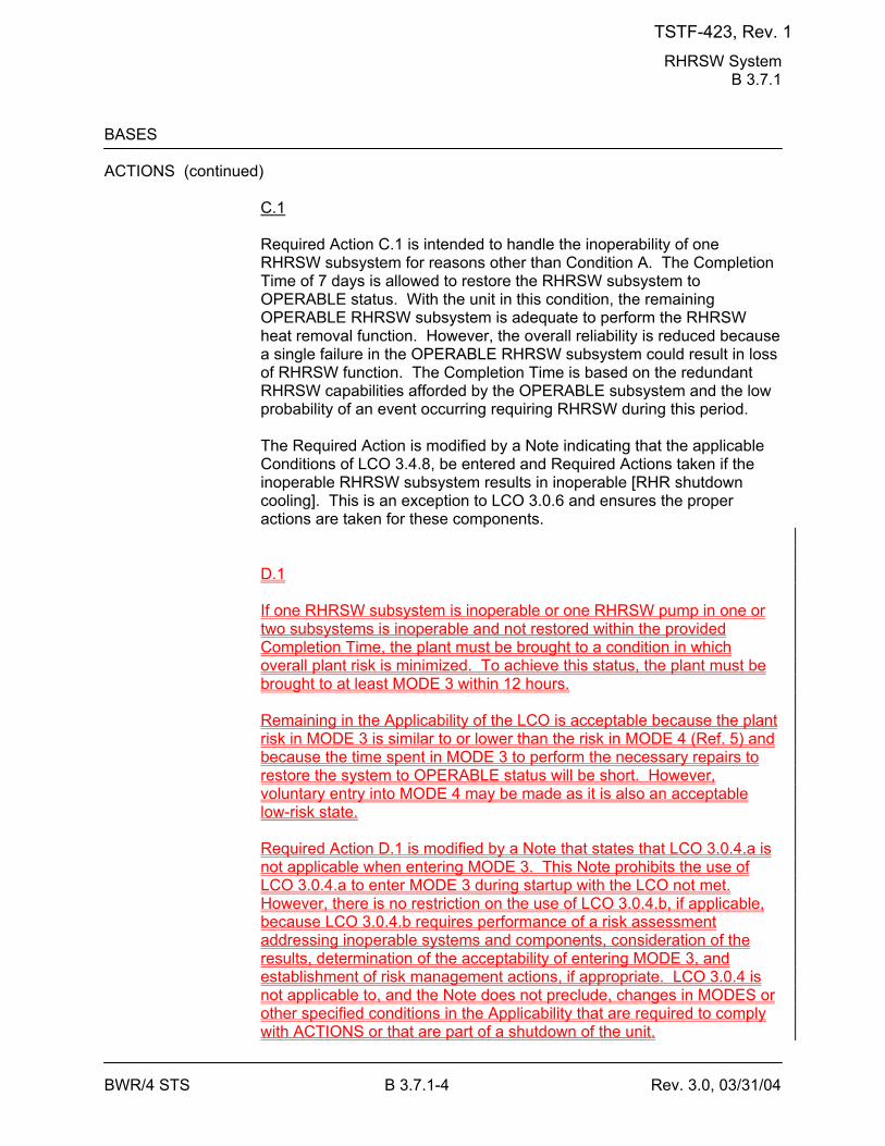
RHRSW System B 3.7.1
BWR/4 STS B 3.7.1-4 Rev. 3.0, 03/31/04
BASES ACTIONS (continued)
C.1 Required Action C.1 is intended to handle the inoperability of one RHRSW subsystem for reasons other than Condition A. The Completion Time of 7 days is allowed to restore the RHRSW subsystem to OPERABLE status. With the unit in this condition, the remaining OPERABLE RHRSW subsystem is adequate to perform the RHRSW heat removal function. However, the overall reliability is reduced because a single failure in the OPERABLE RHRSW subsystem could result in loss of RHRSW function. The Completion Time is based on the redundant RHRSW capabilities afforded by the OPERABLE subsystem and the low probability of an event occurring requiring RHRSW during this period. The Required Action is modified by a Note indicating that the applicable Conditions of LCO 3.4.8, be entered and Required Actions taken if the inoperable RHRSW subsystem results in inoperable [RHR shutdown cooling]. This is an exception to LCO 3.0.6 and ensures the proper actions are taken for these components. D.1 If one RHRSW subsystem is inoperable or one RHRSW pump in one or two subsystems is inoperable and not restored within the provided Completion Time, the plant must be brought to a condition in which overall plant risk is minimized. To achieve this status, the plant must be brought to at least MODE 3 within 12 hours. Remaining in the Applicability of the LCO is acceptable because the plant risk in MODE 3 is similar to or lower than the risk in MODE 4 (Ref. 5) and because the time spent in MODE 3 to perform the necessary repairs to restore the system to OPERABLE status will be short. However, voluntary entry into MODE 4 may be made as it is also an acceptable low-risk state. Required Action D.1 is modified by a Note that states that LCO 3.0.4.a is not applicable when entering MODE 3. This Note prohibits the use of LCO 3.0.4.a to enter MODE 3 during startup with the LCO not met. However, there is no restriction on the use of LCO 3.0.4.b, if applicable, because LCO 3.0.4.b requires performance of a risk assessment addressing inoperable systems and components, consideration of the results, determination of the acceptability of entering MODE 3, and establishment of risk management actions, if appropriate. LCO 3.0.4 is not applicable to, and the Note does not preclude, changes in MODES or other specified conditions in the Applicability that are required to comply with ACTIONS or that are part of a shutdown of the unit.
TSTF-423, Rev. 1
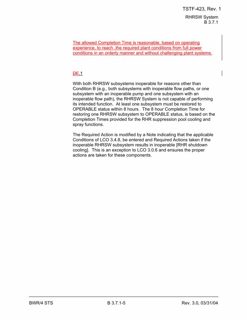
RHRSW System B 3.7.1
BWR/4 STS B 3.7.1-5 Rev. 3.0, 03/31/04
The allowed Completion Time is reasonable, based on operating experience, to reach .the required plant conditions from full power conditions in an orderly manner and without challenging plant systems. DE.1 With both RHRSW subsystems inoperable for reasons other than Condition B (e.g., both subsystems with inoperable flow paths, or one subsystem with an inoperable pump and one subsystem with an inoperable flow path), the RHRSW System is not capable of performing its intended function. At least one subsystem must be restored to OPERABLE status within 8 hours. The 8 hour Completion Time for restoring one RHRSW subsystem to OPERABLE status, is based on the Completion Times provided for the RHR suppression pool cooling and spray functions. The Required Action is modified by a Note indicating that the applicable Conditions of LCO 3.4.8, be entered and Required Actions taken if the inoperable RHRSW subsystem results in inoperable [RHR shutdown cooling]. This is an exception to LCO 3.0.6 and ensures the proper actions are taken for these components.
TSTF-423, Rev. 1
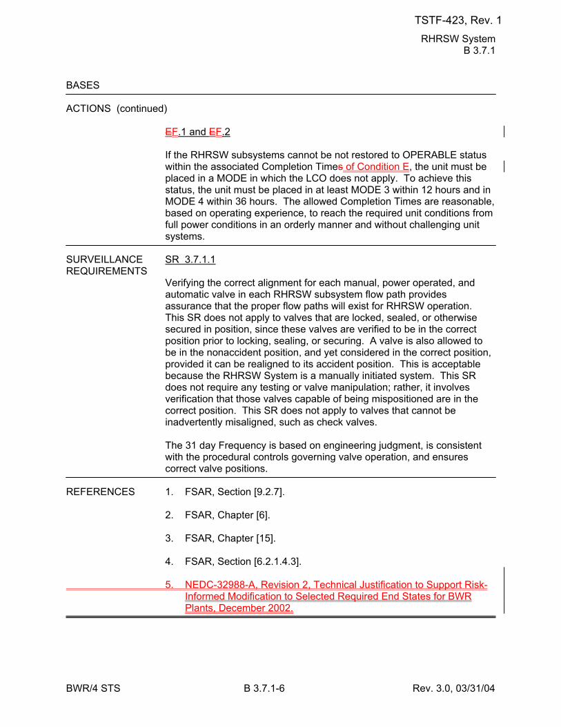
RHRSW System B 3.7.1
BWR/4 STS B 3.7.1-6 Rev. 3.0, 03/31/04
BASES ACTIONS (continued)
EF.1 and EF.2 If the RHRSW subsystems cannot be not restored to OPERABLE status within the associated Completion Times of Condition E, the unit must be placed in a MODE in which the LCO does not apply. To achieve this status, the unit must be placed in at least MODE 3 within 12 hours and in MODE 4 within 36 hours. The allowed Completion Times are reasonable, based on operating experience, to reach the required unit conditions from full power conditions in an orderly manner and without challenging unit systems.
SURVEILLANCE SR 3.7.1.1 REQUIREMENTS
Verifying the correct alignment for each manual, power operated, and automatic valve in each RHRSW subsystem flow path provides assurance that the proper flow paths will exist for RHRSW operation. This SR does not apply to valves that are locked, sealed, or otherwise secured in position, since these valves are verified to be in the correct position prior to locking, sealing, or securing. A valve is also allowed to be in the nonaccident position, and yet considered in the correct position, provided it can be realigned to its accident position. This is acceptable because the RHRSW System is a manually initiated system. This SR does not require any testing or valve manipulation; rather, it involves verification that those valves capable of being mispositioned are in the correct position. This SR does not apply to valves that cannot be inadvertently misaligned, such as check valves. The 31 day Frequency is based on engineering judgment, is consistent with the procedural controls governing valve operation, and ensures correct valve positions.
REFERENCES 1. FSAR, Section [9.2.7]. 2. FSAR, Chapter [6]. 3. FSAR, Chapter [15]. 4. FSAR, Section [6.2.1.4.3]. 5. NEDC-32988-A, Revision 2, Technical Justification to Support Risk-
Informed Modification to Selected Required End States for BWR Plants, December 2002.
TSTF-423, Rev. 1
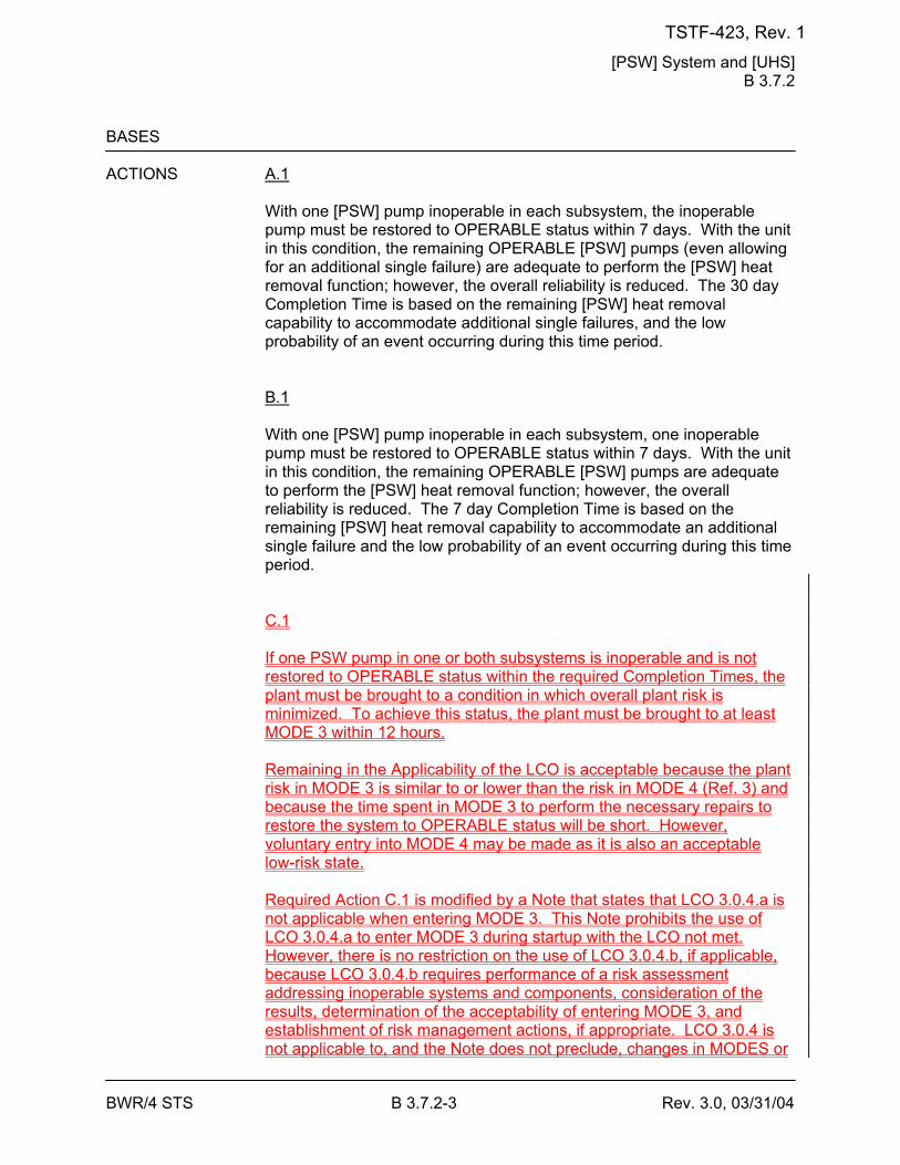
[PSW] System and [UHS] B 3.7.2
BWR/4 STS B 3.7.2-3 Rev. 3.0, 03/31/04
BASES ACTIONS A.1
With one [PSW] pump inoperable in each subsystem, the inoperable pump must be restored to OPERABLE status within 7 days. With the unit in this condition, the remaining OPERABLE [PSW] pumps (even allowing for an additional single failure) are adequate to perform the [PSW] heat removal function; however, the overall reliability is reduced. The 30 day Completion Time is based on the remaining [PSW] heat removal capability to accommodate additional single failures, and the low probability of an event occurring during this time period. B.1 With one [PSW] pump inoperable in each subsystem, one inoperable pump must be restored to OPERABLE status within 7 days. With the unit in this condition, the remaining OPERABLE [PSW] pumps are adequate to perform the [PSW] heat removal function; however, the overall reliability is reduced. The 7 day Completion Time is based on the remaining [PSW] heat removal capability to accommodate an additional single failure and the low probability of an event occurring during this time period. C.1 If one PSW pump in one or both subsystems is inoperable and is not restored to OPERABLE status within the required Completion Times, the plant must be brought to a condition in which overall plant risk is minimized. To achieve this status, the plant must be brought to at least MODE 3 within 12 hours. Remaining in the Applicability of the LCO is acceptable because the plant risk in MODE 3 is similar to or lower than the risk in MODE 4 (Ref. 3) and because the time spent in MODE 3 to perform the necessary repairs to restore the system to OPERABLE status will be short. However, voluntary entry into MODE 4 may be made as it is also an acceptable low-risk state. Required Action C.1 is modified by a Note that states that LCO 3.0.4.a is not applicable when entering MODE 3. This Note prohibits the use of LCO 3.0.4.a to enter MODE 3 during startup with the LCO not met. However, there is no restriction on the use of LCO 3.0.4.b, if applicable, because LCO 3.0.4.b requires performance of a risk assessment addressing inoperable systems and components, consideration of the results, determination of the acceptability of entering MODE 3, and establishment of risk management actions, if appropriate. LCO 3.0.4 is not applicable to, and the Note does not preclude, changes in MODES or
TSTF-423, Rev. 1
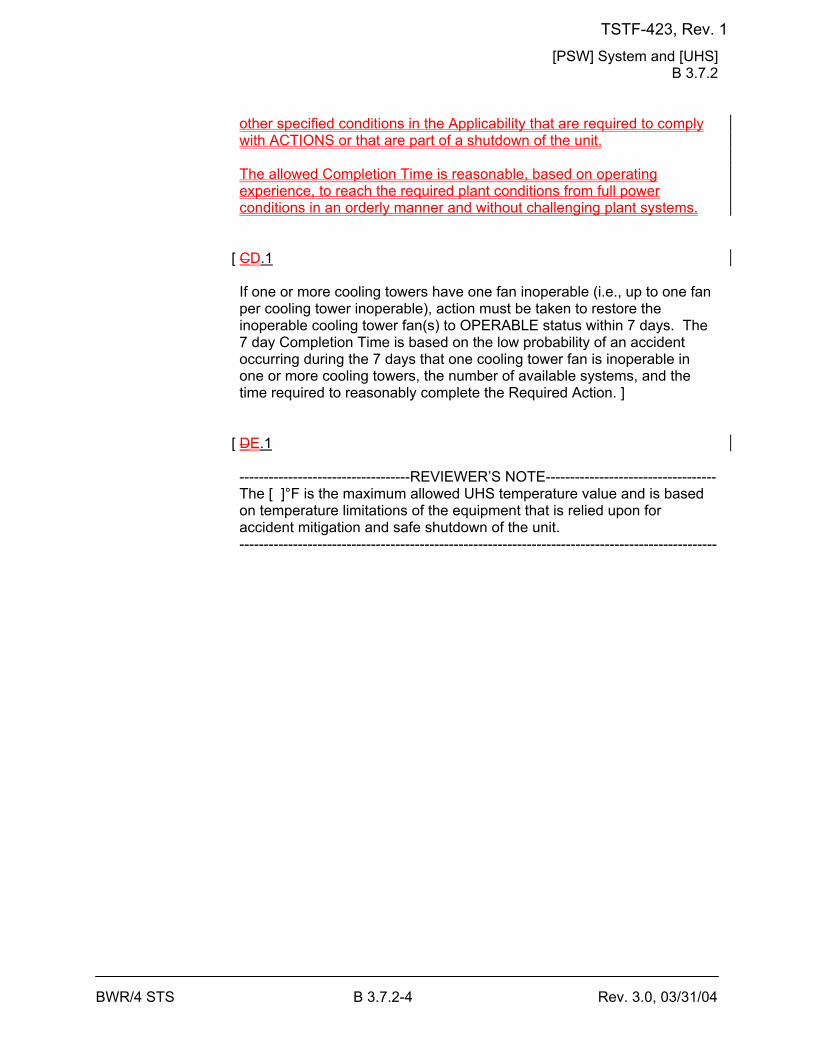
[PSW] System and [UHS] B 3.7.2
BWR/4 STS B 3.7.2-4 Rev. 3.0, 03/31/04
other specified conditions in the Applicability that are required to comply with ACTIONS or that are part of a shutdown of the unit. The allowed Completion Time is reasonable, based on operating experience, to reach the required plant conditions from full power conditions in an orderly manner and without challenging plant systems.
[ CD.1 If one or more cooling towers have one fan inoperable (i.e., up to one fan per cooling tower inoperable), action must be taken to restore the inoperable cooling tower fan(s) to OPERABLE status within 7 days. The 7 day Completion Time is based on the low probability of an accident occurring during the 7 days that one cooling tower fan is inoperable in one or more cooling towers, the number of available systems, and the time required to reasonably complete the Required Action. ]
[ DE.1 -----------------------------------REVIEWER’S NOTE----------------------------------- The [ ]°F is the maximum allowed UHS temperature value and is based on temperature limitations of the equipment that is relied upon for accident mitigation and safe shutdown of the unit. --------------------------------------------------------------------------------------------------
TSTF-423, Rev. 1
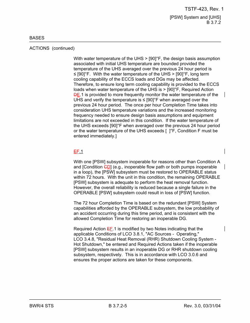
[PSW] System and [UHS] B 3.7.2
BWR/4 STS B 3.7.2-5 Rev. 3.0, 03/31/04
BASES ACTIONS (continued)
With water temperature of the UHS > [90]°F, the design basis assumption associated with initial UHS temperature are bounded provided the temperature of the UHS averaged over the previous 24 hour period is ≤ [90]°F. With the water temperature of the UHS > [90]°F, long term cooling capability of the ECCS loads and DGs may be affected. Therefore, to ensure long term cooling capability is provided to the ECCS loads when water temperature of the UHS is > [90]°F, Required Action DE.1 is provided to more frequently monitor the water temperature of the UHS and verify the temperature is ≤ [90]°F when averaged over the previous 24 hour period. The once per hour Completion Time takes into consideration UHS temperature variations and the increased monitoring frequency needed to ensure design basis assumptions and equipment limitations are not exceeded in this condition. If the water temperature of the UHS exceeds [90]°F when averaged over the previous 24 hour period or the water temperature of the UHS exceeds [ ]°F, Condition F must be entered immediately.] EF.1 With one [PSW] subsystem inoperable for reasons other than Condition A and [Condition CD] (e.g., inoperable flow path or both pumps inoperable in a loop), the [PSW] subsystem must be restored to OPERABLE status within 72 hours. With the unit in this condition, the remaining OPERABLE [PSW] subsystem is adequate to perform the heat removal function. However, the overall reliability is reduced because a single failure in the OPERABLE [PSW] subsystem could result in loss of [PSW] function. The 72 hour Completion Time is based on the redundant [PSW] System capabilities afforded by the OPERABLE subsystem, the low probability of an accident occurring during this time period, and is consistent with the allowed Completion Time for restoring an inoperable DG. Required Action EF.1 is modified by two Notes indicating that the applicable Conditions of LCO 3.8.1, "AC Sources - Operating," LCO 3.4.8, "Residual Heat Removal (RHR) Shutdown Cooling System - Hot Shutdown," be entered and Required Actions taken if the inoperable [PSW] subsystem results in an inoperable DG or RHR shutdown cooling subsystem, respectively. This is in accordance with LCO 3.0.6 and ensures the proper actions are taken for these components.
TSTF-423, Rev. 1
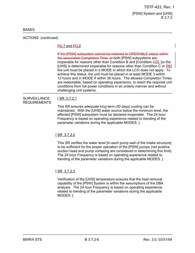
[PSW] System and [UHS] B 3.7.2
BWR/4 STS B 3.7.2-6 Rev. 3.0, 03/31/04
BASES ACTIONS (continued)
FG.1 and FG.2 If the [PSW] subsystem cannot be restored to OPERABLE status within the associated Completion Time, or both [PSW] subsystems are inoperable for reasons other than Condition B and [Condition CD], [or the [UHS] is determined inoperable for reasons other than Condition C or DE] the unit must be placed in a MODE in which the LCO does not apply. To achieve this status, the unit must be placed in at least MODE 3 within 12 hours and in MODE 4 within 36 hours. The allowed Completion Times are reasonable, based on operating experience, to reach the required unit conditions from full power conditions in an orderly manner and without challenging unit systems.
SURVEILLANCE [ SR 3.7.2.1 REQUIREMENTS
This SR ensures adequate long term (30 days) cooling can be maintained. With the [UHS] water source below the minimum level, the affected [PSW] subsystem must be declared inoperable. The 24 hour Frequency is based on operating experience related to trending of the parameter variations during the applicable MODES. ]
[ SR 3.7.2.2 This SR verifies the water level [in each pump well of the intake structure] to be sufficient for the proper operation of the [PSW] pumps (net positive suction head and pump vortexing are considered in determining this limit). The 24 hour Frequency is based on operating experience related to trending of the parameter variations during the applicable MODES. ]
[ SR 3.7.2.3 Verification of the [UHS] temperature ensures that the heat removal capability of the [PSW] System is within the assumptions of the DBA analysis. The 24 hour Frequency is based on operating experience related to trending of the parameter variations during the applicable MODES. ]
TSTF-423, Rev. 1
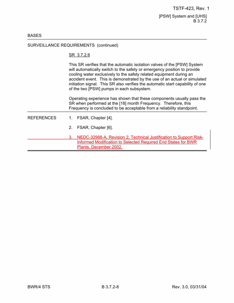
[PSW] System and [UHS] B 3.7.2
BWR/4 STS B 3.7.2-8 Rev. 3.0, 03/31/04
BASES SURVEILLANCE REQUIREMENTS (continued)
SR 3.7.2.6 This SR verifies that the automatic isolation valves of the [PSW] System will automatically switch to the safety or emergency position to provide cooling water exclusively to the safety related equipment during an accident event. This is demonstrated by the use of an actual or simulated initiation signal. This SR also verifies the automatic start capability of one of the two [PSW] pumps in each subsystem. Operating experience has shown that these components usually pass the SR when performed at the [18] month Frequency. Therefore, this Frequency is concluded to be acceptable from a reliability standpoint.
REFERENCES 1. FSAR, Chapter [4]. 2. FSAR, Chapter [6]. 3. NEDC-32988-A, Revision 2, Technical Justification to Support Risk-
Informed Modification to Selected Required End States for BWR Plants, December 2002.
TSTF-423, Rev. 1
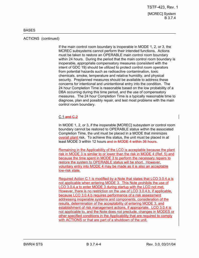
[MCREC] System B 3.7.4
BWR/4 STS B 3.7.4-4 Rev. 3.0, 03/31/04
BASES ACTIONS (continued)
If the main control room boundary is inoperable in MODE 1, 2, or 3, the MCREC subsystems cannot perform their intended functions. Actions must be taken to restore an OPERABLE main control room boundary within 24 hours. During the period that the main control room boundary is inoperable, appropriate compensatory measures (consistent with the intent of GDC 19) should be utilized to protect control room operators from potential hazards such as radioactive contamination, toxic chemicals, smoke, temperature and relative humidity, and physical security. Preplanned measures should be available to address these concerns for intentional and unintentional entry into the condition. The 24 hour Completion Time is reasonable based on the low probability of a DBA occurring during this time period, and the use of compensatory measures. The 24 hour Completion Time is a typically reasonable time to diagnose, plan and possibly repair, and test most problems with the main control room boundary. C.1 and C.2 In MODE 1, 2, or 3, if the inoperable [MCREC] subsystem or control room boundary cannot be restored to OPERABLE status within the associated Completion Time, the unit must be placed in a MODE that minimizes overall plant risk. To achieve this status, the unit must be placed in at least MODE 3 within 12 hours and in MODE 4 within 36 hours. Remaining in the Applicability of the LCO is acceptable because the plant risk in MODE 3 is similar to or lower than the risk in MODE 4 (Ref. 5) and because the time spent in MODE 3 to perform the necessary repairs to restore the system to OPERABLE status will be short. However, voluntary entry into MODE 4 may be made as it is also an acceptable low-risk state. Required Action C.1 is modified by a Note that states that LCO 3.0.4.a is not applicable when entering MODE 3. This Note prohibits the use of LCO 3.0.4.a to enter MODE 3 during startup with the LCO not met. However, there is no restriction on the use of LCO 3.0.4.b, if applicable, because LCO 3.0.4.b requires performance of a risk assessment addressing inoperable systems and components, consideration of the results, determination of the acceptability of entering MODE 3, and establishment of risk management actions, if appropriate. LCO 3.0.4 is not applicable to, and the Note does not preclude, changes in MODES or other specified conditions in the Applicability that are required to comply with ACTIONS or that are part of a shutdown of the unit.
TSTF-423, Rev. 1
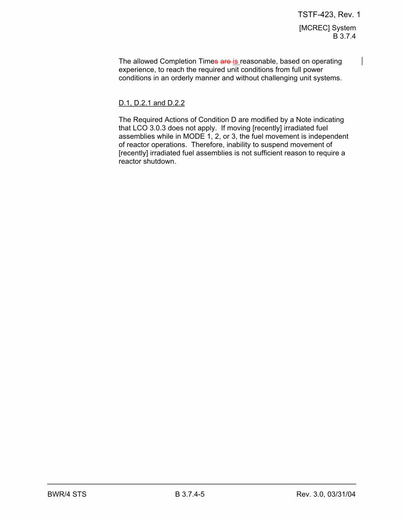
[MCREC] System B 3.7.4
BWR/4 STS B 3.7.4-5 Rev. 3.0, 03/31/04
The allowed Completion Times are is reasonable, based on operating experience, to reach the required unit conditions from full power conditions in an orderly manner and without challenging unit systems. D.1, D.2.1 and D.2.2 The Required Actions of Condition D are modified by a Note indicating that LCO 3.0.3 does not apply. If moving [recently] irradiated fuel assemblies while in MODE 1, 2, or 3, the fuel movement is independent of reactor operations. Therefore, inability to suspend movement of [recently] irradiated fuel assemblies is not sufficient reason to require a reactor shutdown.
TSTF-423, Rev. 1
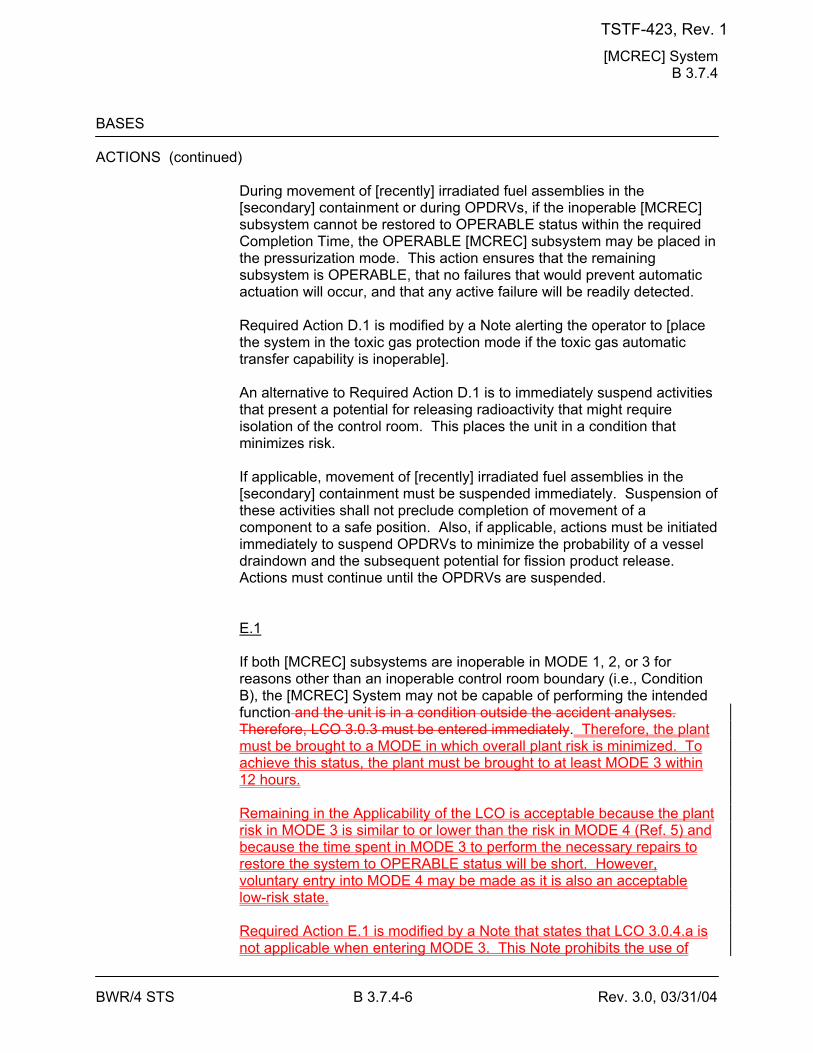
[MCREC] System B 3.7.4
BWR/4 STS B 3.7.4-6 Rev. 3.0, 03/31/04
BASES ACTIONS (continued)
During movement of [recently] irradiated fuel assemblies in the [secondary] containment or during OPDRVs, if the inoperable [MCREC] subsystem cannot be restored to OPERABLE status within the required Completion Time, the OPERABLE [MCREC] subsystem may be placed in the pressurization mode. This action ensures that the remaining subsystem is OPERABLE, that no failures that would prevent automatic actuation will occur, and that any active failure will be readily detected. Required Action D.1 is modified by a Note alerting the operator to [place the system in the toxic gas protection mode if the toxic gas automatic transfer capability is inoperable]. An alternative to Required Action D.1 is to immediately suspend activities that present a potential for releasing radioactivity that might require isolation of the control room. This places the unit in a condition that minimizes risk. If applicable, movement of [recently] irradiated fuel assemblies in the [secondary] containment must be suspended immediately. Suspension of these activities shall not preclude completion of movement of a component to a safe position. Also, if applicable, actions must be initiated immediately to suspend OPDRVs to minimize the probability of a vessel draindown and the subsequent potential for fission product release. Actions must continue until the OPDRVs are suspended. E.1 If both [MCREC] subsystems are inoperable in MODE 1, 2, or 3 for reasons other than an inoperable control room boundary (i.e., Condition B), the [MCREC] System may not be capable of performing the intended function and the unit is in a condition outside the accident analyses. Therefore, LCO 3.0.3 must be entered immediately. Therefore, the plant must be brought to a MODE in which overall plant risk is minimized. To achieve this status, the plant must be brought to at least MODE 3 within 12 hours. Remaining in the Applicability of the LCO is acceptable because the plant risk in MODE 3 is similar to or lower than the risk in MODE 4 (Ref. 5) and because the time spent in MODE 3 to perform the necessary repairs to restore the system to OPERABLE status will be short. However, voluntary entry into MODE 4 may be made as it is also an acceptable low-risk state. Required Action E.1 is modified by a Note that states that LCO 3.0.4.a is not applicable when entering MODE 3. This Note prohibits the use of
TSTF-423, Rev. 1
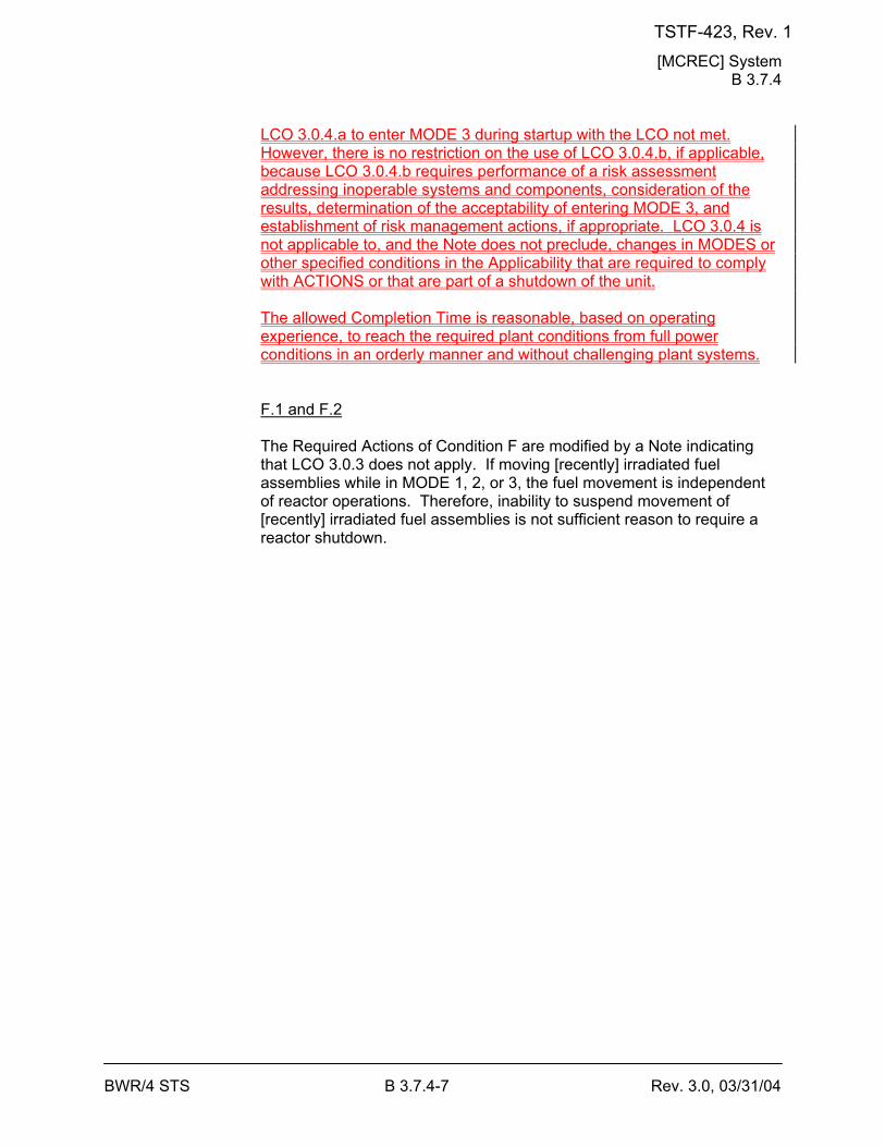
[MCREC] System B 3.7.4
BWR/4 STS B 3.7.4-7 Rev. 3.0, 03/31/04
LCO 3.0.4.a to enter MODE 3 during startup with the LCO not met. However, there is no restriction on the use of LCO 3.0.4.b, if applicable, because LCO 3.0.4.b requires performance of a risk assessment addressing inoperable systems and components, consideration of the results, determination of the acceptability of entering MODE 3, and establishment of risk management actions, if appropriate. LCO 3.0.4 is not applicable to, and the Note does not preclude, changes in MODES or other specified conditions in the Applicability that are required to comply with ACTIONS or that are part of a shutdown of the unit. The allowed Completion Time is reasonable, based on operating experience, to reach the required plant conditions from full power conditions in an orderly manner and without challenging plant systems. F.1 and F.2 The Required Actions of Condition F are modified by a Note indicating that LCO 3.0.3 does not apply. If moving [recently] irradiated fuel assemblies while in MODE 1, 2, or 3, the fuel movement is independent of reactor operations. Therefore, inability to suspend movement of [recently] irradiated fuel assemblies is not sufficient reason to require a reactor shutdown.
TSTF-423, Rev. 1
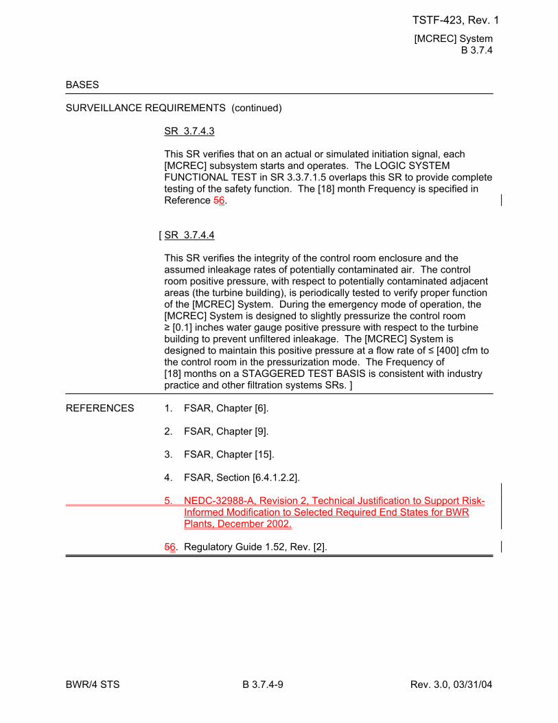
[MCREC] System B 3.7.4
BWR/4 STS B 3.7.4-9 Rev. 3.0, 03/31/04
BASES SURVEILLANCE REQUIREMENTS (continued)
SR 3.7.4.3 This SR verifies that on an actual or simulated initiation signal, each [MCREC] subsystem starts and operates. The LOGIC SYSTEM FUNCTIONAL TEST in SR 3.3.7.1.5 overlaps this SR to provide complete testing of the safety function. The [18] month Frequency is specified in Reference 56.
[ SR 3.7.4.4 This SR verifies the integrity of the control room enclosure and the assumed inleakage rates of potentially contaminated air. The control room positive pressure, with respect to potentially contaminated adjacent areas (the turbine building), is periodically tested to verify proper function of the [MCREC] System. During the emergency mode of operation, the [MCREC] System is designed to slightly pressurize the control room ≥ [0.1] inches water gauge positive pressure with respect to the turbine building to prevent unfiltered inleakage. The [MCREC] System is designed to maintain this positive pressure at a flow rate of ≤ [400] cfm to the control room in the pressurization mode. The Frequency of [18] months on a STAGGERED TEST BASIS is consistent with industry practice and other filtration systems SRs. ]
REFERENCES 1. FSAR, Chapter [6]. 2. FSAR, Chapter [9]. 3. FSAR, Chapter [15]. 4. FSAR, Section [6.4.1.2.2]. 5. NEDC-32988-A, Revision 2, Technical Justification to Support Risk-
Informed Modification to Selected Required End States for BWR Plants, December 2002.
56. Regulatory Guide 1.52, Rev. [2].
TSTF-423, Rev. 1
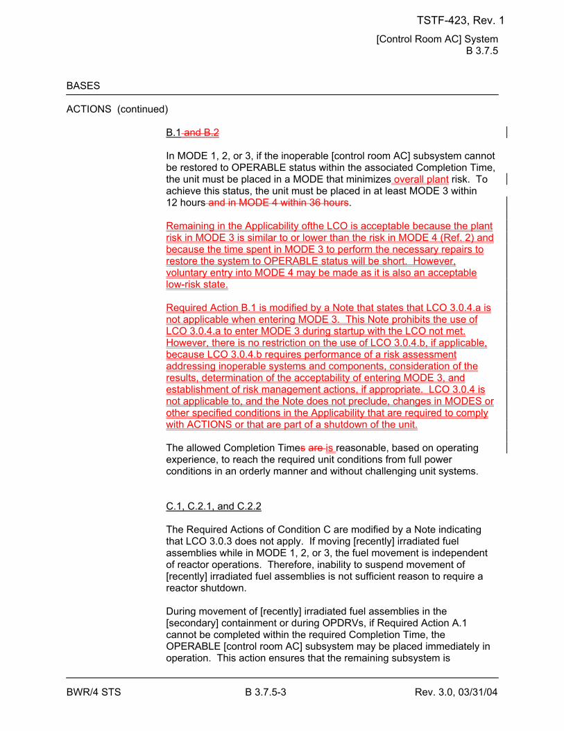
[Control Room AC] System B 3.7.5
BWR/4 STS B 3.7.5-3 Rev. 3.0, 03/31/04
BASES ACTIONS (continued)
B.1 and B.2 In MODE 1, 2, or 3, if the inoperable [control room AC] subsystem cannot be restored to OPERABLE status within the associated Completion Time, the unit must be placed in a MODE that minimizes overall plant risk. To achieve this status, the unit must be placed in at least MODE 3 within 12 hours and in MODE 4 within 36 hours. Remaining in the Applicability ofthe LCO is acceptable because the plant risk in MODE 3 is similar to or lower than the risk in MODE 4 (Ref. 2) and because the time spent in MODE 3 to perform the necessary repairs to restore the system to OPERABLE status will be short. However, voluntary entry into MODE 4 may be made as it is also an acceptable low-risk state. Required Action B.1 is modified by a Note that states that LCO 3.0.4.a is not applicable when entering MODE 3. This Note prohibits the use of LCO 3.0.4.a to enter MODE 3 during startup with the LCO not met. However, there is no restriction on the use of LCO 3.0.4.b, if applicable, because LCO 3.0.4.b requires performance of a risk assessment addressing inoperable systems and components, consideration of the results, determination of the acceptability of entering MODE 3, and establishment of risk management actions, if appropriate. LCO 3.0.4 is not applicable to, and the Note does not preclude, changes in MODES or other specified conditions in the Applicability that are required to comply with ACTIONS or that are part of a shutdown of the unit. The allowed Completion Times are is reasonable, based on operating experience, to reach the required unit conditions from full power conditions in an orderly manner and without challenging unit systems. C.1, C.2.1, and C.2.2 The Required Actions of Condition C are modified by a Note indicating that LCO 3.0.3 does not apply. If moving [recently] irradiated fuel assemblies while in MODE 1, 2, or 3, the fuel movement is independent of reactor operations. Therefore, inability to suspend movement of [recently] irradiated fuel assemblies is not sufficient reason to require a reactor shutdown. During movement of [recently] irradiated fuel assemblies in the [secondary] containment or during OPDRVs, if Required Action A.1 cannot be completed within the required Completion Time, the OPERABLE [control room AC] subsystem may be placed immediately in operation. This action ensures that the remaining subsystem is
TSTF-423, Rev. 1
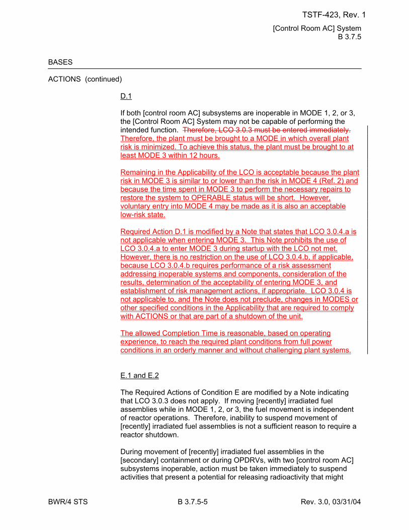
[Control Room AC] System B 3.7.5
BWR/4 STS B 3.7.5-5 Rev. 3.0, 03/31/04
BASES ACTIONS (continued)
D.1 If both [control room AC] subsystems are inoperable in MODE 1, 2, or 3, the [Control Room AC] System may not be capable of performing the intended function. Therefore, LCO 3.0.3 must be entered immediately. Therefore, the plant must be brought to a MODE in which overall plant risk is minimized. To achieve this status, the plant must be brought to at least MODE 3 within 12 hours. Remaining in the Applicability of the LCO is acceptable because the plant risk in MODE 3 is similar to or lower than the risk in MODE 4 (Ref. 2) and because the time spent in MODE 3 to perform the necessary repairs to restore the system to OPERABLE status will be short. However, voluntary entry into MODE 4 may be made as it is also an acceptable low-risk state. Required Action D.1 is modified by a Note that states that LCO 3.0.4.a is not applicable when entering MODE 3. This Note prohibits the use of LCO 3.0.4.a to enter MODE 3 during startup with the LCO not met. However, there is no restriction on the use of LCO 3.0.4.b, if applicable, because LCO 3.0.4.b requires performance of a risk assessment addressing inoperable systems and components, consideration of the results, determination of the acceptability of entering MODE 3, and establishment of risk management actions, if appropriate. LCO 3.0.4 is not applicable to, and the Note does not preclude, changes in MODES or other specified conditions in the Applicability that are required to comply with ACTIONS or that are part of a shutdown of the unit. The allowed Completion Time is reasonable, based on operating experience, to reach the required plant conditions from full power conditions in an orderly manner and without challenging plant systems. E.1 and E.2 The Required Actions of Condition E are modified by a Note indicating that LCO 3.0.3 does not apply. If moving [recently] irradiated fuel assemblies while in MODE 1, 2, or 3, the fuel movement is independent of reactor operations. Therefore, inability to suspend movement of [recently] irradiated fuel assemblies is not a sufficient reason to require a reactor shutdown. During movement of [recently] irradiated fuel assemblies in the [secondary] containment or during OPDRVs, with two [control room AC] subsystems inoperable, action must be taken immediately to suspend activities that present a potential for releasing radioactivity that might
TSTF-423, Rev. 1
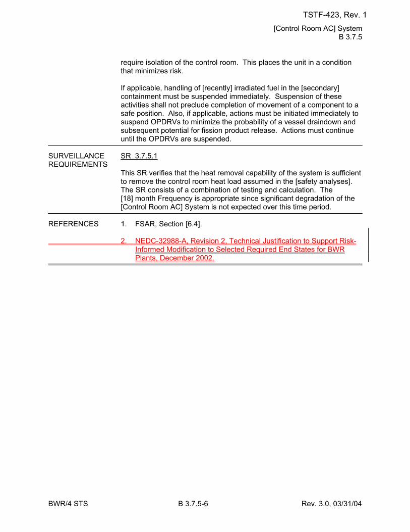
[Control Room AC] System B 3.7.5
BWR/4 STS B 3.7.5-6 Rev. 3.0, 03/31/04
require isolation of the control room. This places the unit in a condition that minimizes risk. If applicable, handling of [recently] irradiated fuel in the [secondary] containment must be suspended immediately. Suspension of these activities shall not preclude completion of movement of a component to a safe position. Also, if applicable, actions must be initiated immediately to suspend OPDRVs to minimize the probability of a vessel draindown and subsequent potential for fission product release. Actions must continue until the OPDRVs are suspended.
SURVEILLANCE SR 3.7.5.1 REQUIREMENTS
This SR verifies that the heat removal capability of the system is sufficient to remove the control room heat load assumed in the [safety analyses]. The SR consists of a combination of testing and calculation. The [18] month Frequency is appropriate since significant degradation of the [Control Room AC] System is not expected over this time period.
REFERENCES 1. FSAR, Section [6.4]. 2. NEDC-32988-A, Revision 2, Technical Justification to Support Risk-
Informed Modification to Selected Required End States for BWR Plants, December 2002.
TSTF-423, Rev. 1
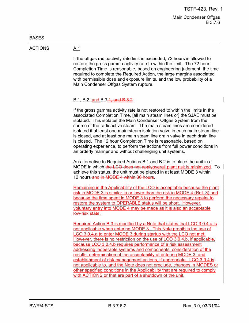
Main Condenser Offgas B 3.7.6
BWR/4 STS B 3.7.6-2 Rev. 3.0, 03/31/04
BASES ACTIONS A.1
If the offgas radioactivity rate limit is exceeded, 72 hours is allowed to restore the gross gamma activity rate to within the limit. The 72 hour Completion Time is reasonable, based on engineering judgment, the time required to complete the Required Action, the large margins associated with permissible dose and exposure limits, and the low probability of a Main Condenser Offgas System rupture. B.1, B.2, and B.3.1, and B.3.2 If the gross gamma activity rate is not restored to within the limits in the associated Completion Time, [all main steam lines or] the SJAE must be isolated. This isolates the Main Condenser Offgas System from the source of the radioactive steam. The main steam lines are considered isolated if at least one main steam isolation valve in each main steam line is closed, and at least one main steam line drain valve in each drain line is closed. The 12 hour Completion Time is reasonable, based on operating experience, to perform the actions from full power conditions in an orderly manner and without challenging unit systems. An alternative to Required Actions B.1 and B.2 is to place the unit in a MODE in which the LCO does not applyoverall plant risk is minimized. To achieve this status, the unit must be placed in at least MODE 3 within 12 hours and in MODE 4 within 36 hours. Remaining in the Applicability of the LCO is acceptable because the plant risk in MODE 3 is similar to or lower than the risk in MODE 4 (Ref. 3) and because the time spent in MODE 3 to perform the necessary repairs to restore the system to OPERABLE status will be short. However, voluntary entry into MODE 4 may be made as it is also an acceptable low-risk state. Required Action B.3 is modified by a Note that states that LCO 3.0.4.a is not applicable when entering MODE 3. This Note prohibits the use of LCO 3.0.4.a to enter MODE 3 during startup with the LCO not met. However, there is no restriction on the use of LCO 3.0.4.b, if applicable, because LCO 3.0.4.b requires performance of a risk assessment addressing inoperable systems and components, consideration of the results, determination of the acceptability of entering MODE 3, and establishment of risk management actions, if appropriate. LCO 3.0.4 is not applicable to, and the Note does not preclude, changes in MODES or other specified conditions in the Applicability that are required to comply with ACTIONS or that are part of a shutdown of the unit.
TSTF-423, Rev. 1
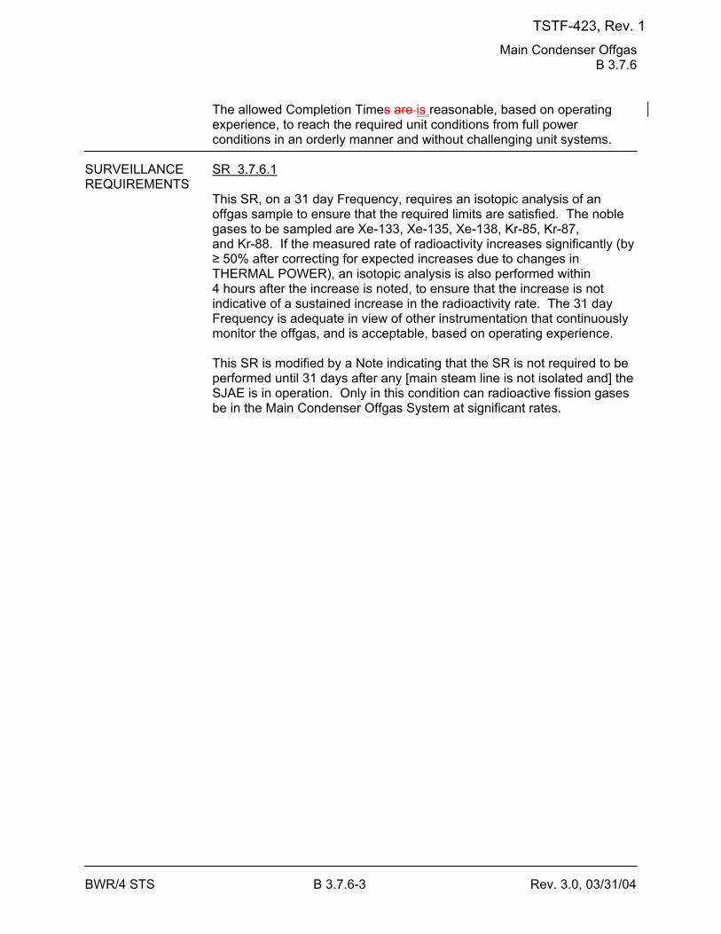
Main Condenser Offgas B 3.7.6
BWR/4 STS B 3.7.6-3 Rev. 3.0, 03/31/04
The allowed Completion Times are is reasonable, based on operating experience, to reach the required unit conditions from full power conditions in an orderly manner and without challenging unit systems.
SURVEILLANCE SR 3.7.6.1 REQUIREMENTS
This SR, on a 31 day Frequency, requires an isotopic analysis of an offgas sample to ensure that the required limits are satisfied. The noble gases to be sampled are Xe-133, Xe-135, Xe-138, Kr-85, Kr-87, and Kr-88. If the measured rate of radioactivity increases significantly (by ≥ 50% after correcting for expected increases due to changes in THERMAL POWER), an isotopic analysis is also performed within 4 hours after the increase is noted, to ensure that the increase is not indicative of a sustained increase in the radioactivity rate. The 31 day Frequency is adequate in view of other instrumentation that continuously monitor the offgas, and is acceptable, based on operating experience. This SR is modified by a Note indicating that the SR is not required to be performed until 31 days after any [main steam line is not isolated and] the SJAE is in operation. Only in this condition can radioactive fission gases be in the Main Condenser Offgas System at significant rates.
TSTF-423, Rev. 1
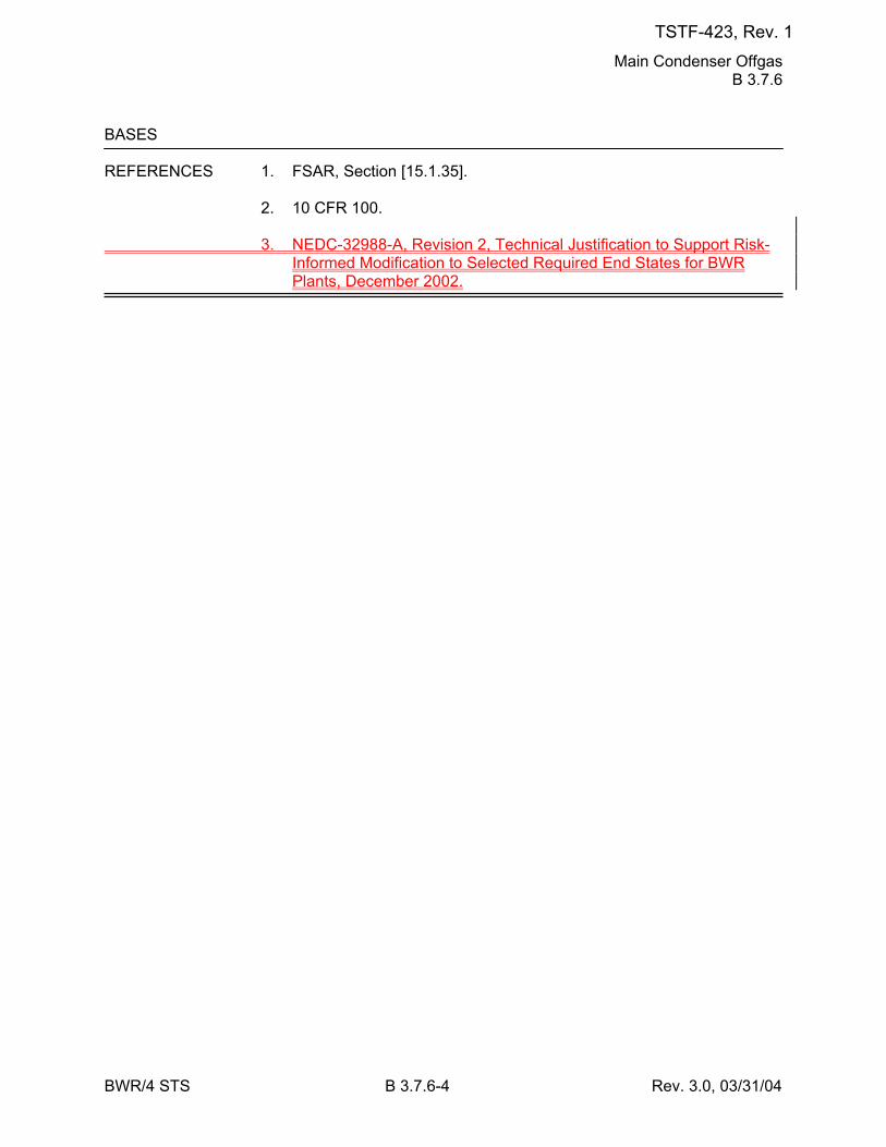
Main Condenser Offgas B 3.7.6
BWR/4 STS B 3.7.6-4 Rev. 3.0, 03/31/04
BASES REFERENCES 1. FSAR, Section [15.1.35]. 2. 10 CFR 100. 3. NEDC-32988-A, Revision 2, Technical Justification to Support Risk-
Informed Modification to Selected Required End States for BWR Plants, December 2002.
TSTF-423, Rev. 1
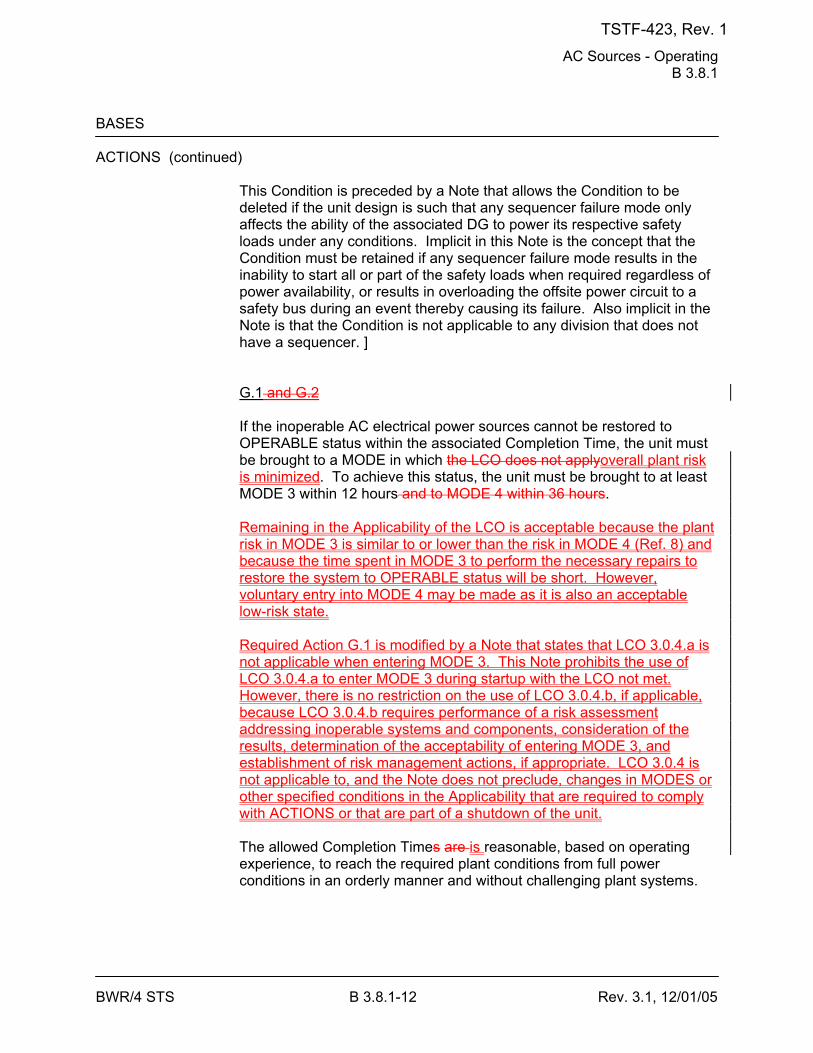
AC Sources - Operating B 3.8.1
BWR/4 STS B 3.8.1-12 Rev. 3.1, 12/01/05
BASES ACTIONS (continued)
This Condition is preceded by a Note that allows the Condition to be deleted if the unit design is such that any sequencer failure mode only affects the ability of the associated DG to power its respective safety loads under any conditions. Implicit in this Note is the concept that the Condition must be retained if any sequencer failure mode results in the inability to start all or part of the safety loads when required regardless of power availability, or results in overloading the offsite power circuit to a safety bus during an event thereby causing its failure. Also implicit in the Note is that the Condition is not applicable to any division that does not have a sequencer. ] G.1 and G.2 If the inoperable AC electrical power sources cannot be restored to OPERABLE status within the associated Completion Time, the unit must be brought to a MODE in which the LCO does not applyoverall plant risk is minimized. To achieve this status, the unit must be brought to at least MODE 3 within 12 hours and to MODE 4 within 36 hours. Remaining in the Applicability of the LCO is acceptable because the plant risk in MODE 3 is similar to or lower than the risk in MODE 4 (Ref. 8) and because the time spent in MODE 3 to perform the necessary repairs to restore the system to OPERABLE status will be short. However, voluntary entry into MODE 4 may be made as it is also an acceptable low-risk state. Required Action G.1 is modified by a Note that states that LCO 3.0.4.a is not applicable when entering MODE 3. This Note prohibits the use of LCO 3.0.4.a to enter MODE 3 during startup with the LCO not met. However, there is no restriction on the use of LCO 3.0.4.b, if applicable, because LCO 3.0.4.b requires performance of a risk assessment addressing inoperable systems and components, consideration of the results, determination of the acceptability of entering MODE 3, and establishment of risk management actions, if appropriate. LCO 3.0.4 is not applicable to, and the Note does not preclude, changes in MODES or other specified conditions in the Applicability that are required to comply with ACTIONS or that are part of a shutdown of the unit. The allowed Completion Times are is reasonable, based on operating experience, to reach the required plant conditions from full power conditions in an orderly manner and without challenging plant systems.
TSTF-423, Rev. 1
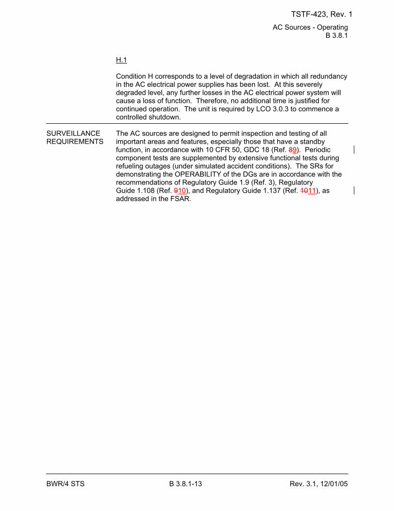
AC Sources - Operating B 3.8.1
BWR/4 STS B 3.8.1-13 Rev. 3.1, 12/01/05
H.1 Condition H corresponds to a level of degradation in which all redundancy in the AC electrical power supplies has been lost. At this severely degraded level, any further losses in the AC electrical power system will cause a loss of function. Therefore, no additional time is justified for continued operation. The unit is required by LCO 3.0.3 to commence a controlled shutdown.
SURVEILLANCE The AC sources are designed to permit inspection and testing of all REQUIREMENTS important areas and features, especially those that have a standby
function, in accordance with 10 CFR 50, GDC 18 (Ref. 89). Periodic component tests are supplemented by extensive functional tests during refueling outages (under simulated accident conditions). The SRs for demonstrating the OPERABILITY of the DGs are in accordance with the recommendations of Regulatory Guide 1.9 (Ref. 3), Regulatory Guide 1.108 (Ref. 910), and Regulatory Guide 1.137 (Ref. 1011), as addressed in the FSAR.
TSTF-423, Rev. 1
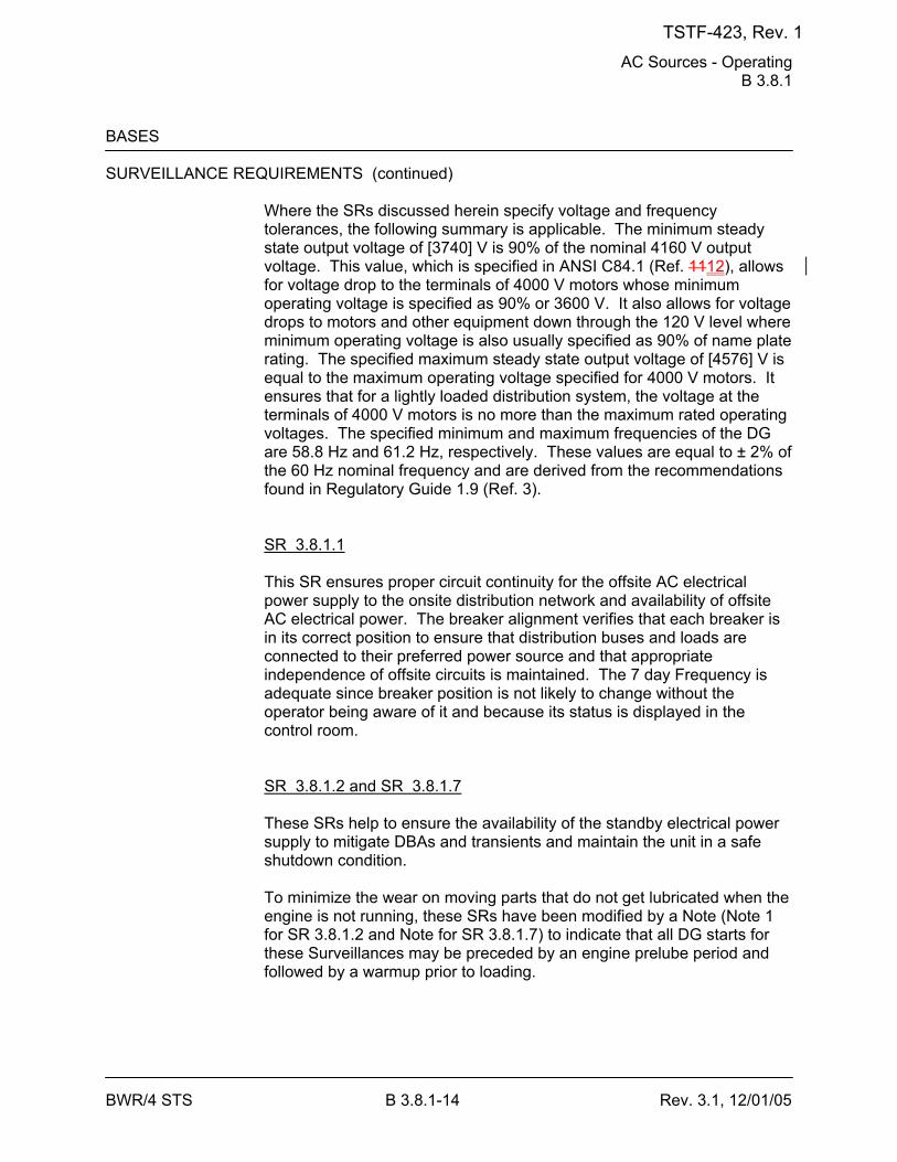
AC Sources - Operating B 3.8.1
BWR/4 STS B 3.8.1-14 Rev. 3.1, 12/01/05
BASES SURVEILLANCE REQUIREMENTS (continued)
Where the SRs discussed herein specify voltage and frequency tolerances, the following summary is applicable. The minimum steady state output voltage of [3740] V is 90% of the nominal 4160 V output voltage. This value, which is specified in ANSI C84.1 (Ref. 1112), allows for voltage drop to the terminals of 4000 V motors whose minimum operating voltage is specified as 90% or 3600 V. It also allows for voltage drops to motors and other equipment down through the 120 V level where minimum operating voltage is also usually specified as 90% of name plate rating. The specified maximum steady state output voltage of [4576] V is equal to the maximum operating voltage specified for 4000 V motors. It ensures that for a lightly loaded distribution system, the voltage at the terminals of 4000 V motors is no more than the maximum rated operating voltages. The specified minimum and maximum frequencies of the DG are 58.8 Hz and 61.2 Hz, respectively. These values are equal to ± 2% of the 60 Hz nominal frequency and are derived from the recommendations found in Regulatory Guide 1.9 (Ref. 3). SR 3.8.1.1 This SR ensures proper circuit continuity for the offsite AC electrical power supply to the onsite distribution network and availability of offsite AC electrical power. The breaker alignment verifies that each breaker is in its correct position to ensure that distribution buses and loads are connected to their preferred power source and that appropriate independence of offsite circuits is maintained. The 7 day Frequency is adequate since breaker position is not likely to change without the operator being aware of it and because its status is displayed in the control room. SR 3.8.1.2 and SR 3.8.1.7 These SRs help to ensure the availability of the standby electrical power supply to mitigate DBAs and transients and maintain the unit in a safe shutdown condition. To minimize the wear on moving parts that do not get lubricated when the engine is not running, these SRs have been modified by a Note (Note 1 for SR 3.8.1.2 and Note for SR 3.8.1.7) to indicate that all DG starts for these Surveillances may be preceded by an engine prelube period and followed by a warmup prior to loading.
TSTF-423, Rev. 1
AC Sources - Operating B 3.8.1
BWR/4 STS B 3.8.1-15 Rev. 3.1, 12/01/05
BASES SURVEILLANCE REQUIREMENTS (continued)
For the purposes of this testing, the DGs are started from standby conditions. Standby conditions for a DG mean that the diesel engine coolant and oil are being continuously circulated and temperature is being maintained consistent with manufacturer recommendations.
[ In order to reduce stress and wear on diesel engines, some manufacturers recommend a modified start in which the starting speed of DGs is limited, warmup is limited to this lower speed, and the DGs are gradually accelerated to synchronous speed prior to loading. These start procedures are the intent of Note 2, which is only applicable when such modified start procedures are recommended by the manufacturer. ] SR 3.8.1.7 requires that, at a 184 day Frequency, the DG starts from standby conditions and achieves required voltage and frequency within 12 seconds. The 12 second start requirement supports the assumptions in the design basis LOCA analysis of FSAR, Section [6.3] (Ref. 1213). The 12 second start requirement is not applicable to SR 3.8.1.2 (see Note 2 of SR 3.8.1.2), when a modified start procedure as described above is used. If a modified start is not used, the 12 second start requirement of SR 3.8.1.7 applies. Since SR 3.8.1.7 does require a 12 second start, it is more restrictive than SR 3.8.1.2, and it may be performed in lieu of SR 3.8.1.2. In addition to the SR requirements, the time for the DG to reach steady state operation, unless the modified DG start method is employed, is periodically monitored and the trend evaluated to identify degradation of governor and voltage regulator performance. The 31 day Frequency for SR 3.8.1.2 is consistent with Regulatory Guide 1.9 (Ref. 3). The 184 day Frequency for SR 3.8.1.7 is a reduction in cold testing consistent with Generic Letter 84-15 (Ref. 7). These Frequencies provide adequate assurance of DG OPERABILITY, while minimizing degradation resulting from testing. SR 3.8.1.3 This Surveillance verifies that the DGs are capable of synchronizing and accepting greater than or equal to the equivalent of the maximum expected accident loads. A minimum run time of 60 minutes is required to stabilize engine temperatures, while minimizing the time that the DG is connected to the offsite source.
TSTF-423, Rev. 1
AC Sources - Operating B 3.8.1
BWR/4 STS B 3.8.1-17 Rev. 3.1, 12/01/05
BASES SURVEILLANCE REQUIREMENTS (continued)
SR 3.8.1.5 Microbiological fouling is a major cause of fuel oil degradation. There are numerous bacteria that can grow in fuel oil and cause fouling, but all must have a water environment in order to survive. Removal of water from the fuel oil day [and engine mounted] tanks once every [31] days eliminates the necessary environment for bacterial survival. This is the most effective means of controlling microbiological fouling. In addition, it eliminates the potential for water entrainment in the fuel oil during DG operation. Water may come from any of several sources, including condensation, ground water, rain water, contaminated fuel oil, and breakdown of the fuel oil by bacteria. Frequent checking for and removal of accumulated water minimizes fouling and provides data regarding the watertight integrity of the fuel oil system. The Surveillance Frequencies are established by Regulatory Guide 1.137 (Ref. 1011). This SR is for preventive maintenance. The presence of water does not necessarily represent a failure of this SR provided that accumulated water is removed during performance of this Surveillance. SR 3.8.1.6 This Surveillance demonstrates that each required fuel oil transfer pump operates and transfers fuel oil from its associated storage tank to its associated day tank. It is required to support continuous operation of standby power sources. This Surveillance provides assurance that the fuel oil transfer pump is OPERABLE, the fuel oil piping system is intact, the fuel delivery piping is not obstructed, and the controls and control systems for automatic fuel transfer systems are OPERABLE.
[ The Frequency for this SR is variable, depending on individual system design, with up to a [92] day interval. The [92] day Frequency corresponds to the testing requirements for pumps as contained in the ASME Boiler and Pressure Vessel Code (Ref. 1314); however, the design of fuel transfer systems is such that pumps operate automatically or must be started manually in order to maintain an adequate volume of fuel oil in the day [and engine mounted] tanks during or following DG testing. In such a case, a 31 day Frequency is appropriate. Since proper operation of fuel transfer systems is an inherent part of DG OPERABILITY, the Frequency of this SR should be modified to reflect individual designs. ] SR 3.8.1.7 See SR 3.8.1.2.
TSTF-423, Rev. 1
AC Sources - Operating B 3.8.1
BWR/4 STS B 3.8.1-18 Rev. 3.1, 12/01/05
BASES SURVEILLANCE REQUIREMENTS (continued)
[ SR 3.8.1.8 Transfer of each 4.16 kV ESF bus power supply from the normal offsite circuit to the alternate offsite circuit demonstrates the OPERABILITY of the alternate circuit distribution network to power the shutdown loads. The [18 month] Frequency of the Surveillance is based on engineering judgment taking into consideration the plant conditions required to perform the Surveillance, and is intended to be consistent with expected fuel cycle lengths. Operating experience has shown that these components usually pass the SR when performed on the 18 month Frequency. Therefore, the Frequency was concluded to be acceptable from a reliability standpoint. ] This SR is modified by a Note. The reason for the Note is that, during operation with the reactor critical, performance of this SR could cause perturbations to the electrical distribution systems that could challenge continued steady state operation and, as a result, plant safety systems. This restriction from normally performing the Surveillance in MODE 1 or 2 is further amplified to allow the Surveillance to be performed for the purpose of reestablishing OPERABILITY (e.g., post work testing following corrective maintenance, corrective modification, deficient or incomplete surveillance testing, and other unanticipated OPERABILITY concerns) provided an assessment determines plant safety is maintained or enhanced. This assessment shall, as a minimum, consider the potential outcomes and transients associated with a failed Surveillance, a successful Surveillance, and a perturbation of the offsite or onsite system when they are tied together or operated independently for the Surveillance; as well as the operator procedures available to cope with these outcomes. These shall be measured against the avoided risk of a plant shutdown and startup to determine that plant safety is maintained or enhanced when the Surveillance is performed in MODE 1 or 2. Risk insights or deterministic methods may be used for this assessment. Credit may be taken for unplanned events that satisfy this SR. SR 3.8.1.9 Each DG is provided with an engine overspeed trip to prevent damage to the engine. Recovery from the transient caused by the loss of a large load could cause diesel engine overspeed, which, if excessive, might result in a trip of the engine. This Surveillance demonstrates the DG load response characteristics and capability to reject the largest single load without exceeding predetermined voltage and frequency and while maintaining a specified margin to the overspeed trip. The largest single load for each DG is a residual heat removal service water pump (1225 bhp). This Surveillance may be accomplished by either:
TSTF-423, Rev. 1
AC Sources - Operating B 3.8.1
BWR/4 STS B 3.8.1-19 Rev. 3.1, 12/01/05
BASES SURVEILLANCE REQUIREMENTS (continued)
a. Tripping the DG output breaker with the DG carrying greater than or
equal to its associated single largest post-accident load while paralleled to offsite power, or while solely supplying the bus, or
b. Tripping its associated single largest post-accident load with the DG
solely supplying the bus. As required by IEEE-308 (Ref. 1415), the load rejection test is acceptable if the increase in diesel speed does not exceed 75% of the difference between synchronous speed and the overspeed trip setpoint, or 15% above synchronous speed, whichever is lower. For DGs 2A, 2C, and 1B, this represents 65.5 Hz, equivalent to 75% of the difference between nominal speed and the overspeed trip setpoint. The time, voltage, and frequency tolerances specified in this SR are derived from Regulatory Guide 1.9 (Ref. 3) recommendations for response during load sequence intervals. The [6] seconds specified is equal to 60% of the 10 second load sequence interval associated with sequencing the residual heat removal (RHR) pumps during an undervoltage on the bus concurrent with a LOCA. The voltage and frequency specified are consistent with the design range of the equipment powered by the DG. SR 3.8.1.9.a corresponds to the maximum frequency excursion, while SR 3.8.1.9.b and SR 3.8.1.9.c are steady state voltage and frequency values to which the system must recover following load rejection. The [18 month] Frequency is consistent with the recommendation of Regulatory Guide 1.108 (Ref. 910). This SR is modified by two Notes. The reason for Note 1 is that, during operation with the reactor critical, performance of this SR could cause perturbations to the electrical distribution systems that could challenge continued steady state operation and, as a result, plant safety systems. This restriction from normally performing the Surveillance in MODE 1 or 2 is further amplified to allow the Surveillance to be performed for the purpose of reestablishing OPERABILITY (e.g., post work testing following corrective maintenance, corrective modification, deficient or incomplete surveillance testing, and other unanticipated OPERABILITY concerns) provided an assessment determines plant safety is maintained or enhanced. This assessment shall, as a minimum, consider the potential outcomes and transients associated with a failed Surveillance, a successful Surveillance, and a perturbation of the offsite or onsite system when they are tied together or operated independently for the
TSTF-423, Rev. 1
AC Sources - Operating B 3.8.1
BWR/4 STS B 3.8.1-21 Rev. 3.1, 12/01/05
BASES SURVEILLANCE REQUIREMENTS (continued)
SR 3.8.1.10 This Surveillance demonstrates the DG capability to reject a full load without overspeed tripping or exceeding the predetermined voltage limits. The DG full load rejection may occur because of a system fault or inadvertent breaker tripping. This Surveillance ensures proper engine generator load response under the simulated test conditions. This test simulates the loss of the total connected load that the DG experiences following a full load rejection and verifies that the DG does not trip upon loss of the load. These acceptance criteria provide DG damage protection. While the DG is not expected to experience this transient during an event, and continues to be available, this response ensures that the DG is not degraded for future application, including reconnection to the bus if the trip initiator can be corrected or isolated. The [18 month] Frequency is consistent with the recommendation of Regulatory Guide 1.108 (Ref. 910) and is intended to be consistent with expected fuel cycle lengths. This SR is modified by two Notes. The reason for Note 1 is that during operation with the reactor critical, performance of this SR could cause perturbations to the electrical distribution systems that would challenge continued steady state operation and, as a result, plant safety systems. This restriction from normally performing the Surveillance in MODE 1 or 2 is further amplified to allow the Surveillance to be performed for the purpose of reestablishing OPERABILITY (e.g., post work testing following corrective maintenance, corrective modification, deficient or incomplete surveillance testing, and other unanticipated OPERABILITY concerns) provided an assessment determines plant safety is maintained or enhanced. This assessment shall, as a minimum, consider the potential outcomes and transients associated with a failed Surveillance, a successful Surveillance, and a perturbation of the offsite or onsite system when they are tied together or operated independently for the Surveillance; as well as the operator procedures available to cope with these outcomes. These shall be measured against the avoided risk of a plant shutdown and startup to determine that plant safety is maintained or enhanced when the Surveillance is performed in MODE 1 or 2. Risk insights or deterministic methods may be used for this assessment. Credit may be taken for unplanned events that satisfy this SR. Note 2 ensures that the DG is tested under load conditions that are as close to design basis conditions as possible. When synchronized with offsite
TSTF-423, Rev. 1
AC Sources - Operating B 3.8.1
BWR/4 STS B 3.8.1-22 Rev. 3.1, 12/01/05
BASES SURVEILLANCE REQUIREMENTS (continued)
power, testing should be performed at a power factor of ≤ [0.9]. This power factor is representative of the actual inductive loading a DG would see under design basis accident conditions. Under certain conditions, however, Note 2 allows the surveillance to be conducted at a power factor other than ≤ [0.9]. These conditions occur when grid voltage is high, and the additional field excitation needed to get the power factor to ≤ [0.9] results in voltages on the emergency busses that are too high. Under these conditions, the power factor should be maintained as close as practicable to [0.9] while still maintaining acceptable voltage limits on the emergency busses. In other circumstances, the grid voltage may be such that the DG excitation levels needed to obtain a power factor of [0.9] may not cause unacceptable voltages on the emergency busses, but the excitation levels are in excess of those recommended for the DG. In such cases, the power factor shall be maintained as close as practicable to [0.9] without exceeding the DG excitation limits. -----------------------------------REVIEWER’S NOTE----------------------------------- The above MODE restrictions may be deleted if it can be demonstrated to the staff, on a plant specific basis, that performing the SR with the reactor in any of the restricted MODES can satisfy the following criteria, as applicable: a. Performance of the SR will not render any safety system or
component inoperable, b. Performance of the SR will not cause perturbations to any of the
electrical distribution systems that could result in a challenge to steady state operation or to plant safety systems, and
c. Performance of the SR, or failure of the SR, will not cause, or result
in, an AOO with attendant challenge to plant safety systems. -------------------------------------------------------------------------------------------------- SR 3.8.1.11 As required by Regulatory Guide 1.108 (Ref. 910), paragraph 2.a.(1), this Surveillance demonstrates the as designed operation of the standby power sources during loss of the offsite source. This test verifies all actions encountered from the loss of offsite power, including shedding of the nonessential loads and energization of the emergency buses and respective loads from the DG. It further demonstrates the capability of the DG to automatically achieve the required voltage and frequency within the specified time.
TSTF-423, Rev. 1
AC Sources - Operating B 3.8.1
BWR/4 STS B 3.8.1-23 Rev. 3.1, 12/01/05
BASES SURVEILLANCE REQUIREMENTS (continued)
The DG auto-start time of 12 seconds is derived from requirements of the accident analysis for responding to a design basis large break LOCA. The Surveillance should be continued for a minimum of 5 minutes in order to demonstrate that all starting transients have decayed and stability has been achieved. The requirement to verify the connection and power supply of permanent and auto-connected loads is intended to satisfactorily show the relationship of these loads to the DG loading logic. In certain circumstances, many of these loads cannot actually be connected or loaded without undue hardship or potential for undesired operation. For instance, Emergency Core Cooling Systems (ECCS) injection valves are not desired to be stroked open, or systems are not capable of being operated at full flow, or RHR systems performing a decay heat removal function are not desired to be realigned to the ECCS mode of operation. In lieu of actual demonstration of the connection and loading of these loads, testing that adequately shows the capability of the DG system to perform these functions is acceptable. This testing may include any series of sequential, overlapping, or total steps so that the entire connection and loading sequence is verified. The Frequency of [18 months] is consistent with the recommendations of Regulatory Guide 1.108 (Ref. 910), paragraph 2.a.(1), takes into consideration plant conditions required to perform the Surveillance, and is intended to be consistent with expected fuel cycle lengths. This SR is modified by two Notes. The reason for Note 1 is to minimize wear and tear on the DGs during testing. For the purpose of this testing, the DGs shall be started from standby conditions, that is, with the engine coolant and oil being continuously circulated and temperature maintained consistent with manufacturer recommendations. The reason for Note 2 is that performing the Surveillance would remove a required offsite circuit from service, perturb the electrical distribution system, and challenge safety systems. This restriction from normally performing the Surveillance in MODE 1 or 2 is further amplified to allow portions of the Surveillance to be performed for the purpose of reestablishing OPERABILITY (e.g., post work testing following corrective maintenance, corrective modification, deficient or incomplete surveillance testing, and other unanticipated OPERABILITY concerns) provided an assessment determines plant safety is maintained or enhanced. This assessment shall, as a minimum, consider the potential outcomes and transients
TSTF-423, Rev. 1
AC Sources - Operating B 3.8.1
BWR/4 STS B 3.8.1-27 Rev. 3.1, 12/01/05
BASES SURVEILLANCE REQUIREMENTS (continued)
SR 3.8.1.14 Regulatory Guide 1.108 (Ref. 910), paragraph 2.a.(3), requires demonstration once per [18 months] that the DGs can start and run continuously at full load capability for an interval of not less than 24 hours - 22 hours of which is at a load equivalent to the continuous rating of the DG, and 2 hours of which is at a load equivalent to 110% of the continuous duty rating of the DG. Plant Hatch has taken an exception to this requirement and performs the 2 hour run at the 2000 hour rating (3100 kW). The DG starts for this Surveillance can be performed either from standby or hot conditions. The provisions for prelube and warmup, discussed in SR 3.8.1.2, and for gradual loading, discussed in SR 3.8.1.3, are applicable to this SR. A load band is provided to avoid routine overloading of the DG. Routine overloading may result in more frequent teardown inspections in accordance with vendor recommendations in order to maintain DG OPERABILITY. The [18 month] Frequency is consistent with the recommendations of Regulatory Guide 1.108 (Ref. 910), paragraph 2.a.(3); takes into consideration plant conditions required to perform the Surveillance; and is intended to be consistent with expected fuel cycle lengths. This Surveillance has been modified by three Notes. Note 1 states that momentary transients due to changing bus loads do not invalidate this test. Similarly, momentary power factor transients above the limit do not invalidate the test. The reason for Note 2 is that during operation with the reactor critical, performance of this Surveillance could cause perturbations to the electrical distribution systems that would challenge continued steady state operation and, as a result, plant safety systems. This restriction from normally performing the Surveillance in MODE 1 or 2 is further amplified to allow the Surveillance to be performed for the purpose of reestablishing OPERABILITY (e.g., post work testing following corrective maintenance, corrective modification, deficient or incomplete surveillance testing, and other unanticipated OPERABILITY concerns) provided an assessment determines plant safety is maintained or enhanced. This assessment shall, as a minimum, consider the potential outcomes and transients associated with a failed Surveillance, a successful Surveillance, and a perturbation of the offsite or onsite system when they are tied together or operated independently for the
TSTF-423, Rev. 1
AC Sources - Operating B 3.8.1
BWR/4 STS B 3.8.1-28 Rev. 3.1, 12/01/05
BASES SURVEILLANCE REQUIREMENTS (continued)
Surveillance; as well as the operator procedures available to cope with these outcomes. These shall be measured against the avoided risk of a plant shutdown and startup to determine that plant safety is maintained or enhanced when the Surveillance is performed in MODE 1 or 2. Risk insights or deterministic methods may be used for this assessment. Credit may be taken for unplanned events that satisfy this SR. Note 3 ensures that the DG is tested under load conditions that are as close to design basis conditions as possible. When synchronized with offsite power, testing should be performed at a power factor of ≤ [0.9]. This power factor is representative of the actual inductive loading a DG would see under design basis accident conditions. Under certain conditions, however, Note 3 allows the surveillance to be conducted at a power factor other than ≤ [0.9]. These conditions occur when grid voltage is high, and the additional field excitation needed to get the power factor to ≤ [0.9] results in voltages on the emergency busses that are too high. Under these conditions, the power factor should be maintained as close as practicable to [0.9] while still maintaining acceptable voltage limits on the emergency busses. In other circumstances, the grid voltage may be such that the DG excitation levels needed to obtain a power factor of [0.9] may not cause unacceptable voltages on the emergency busses, but the excitation levels are in excess of those recommended for the DG. In such cases, the power factor shall be maintained as close as practicable to [0.9] without exceeding the DG excitation limits. SR 3.8.1.15 This Surveillance demonstrates that the diesel engine can restart from a hot condition, such as subsequent to shutdown from normal Surveillances, and achieve the required voltage and frequency within [12] seconds. The [12] second time is derived from the requirements of the accident analysis to respond to a design basis large break LOCA. The [18 month] Frequency is consistent with the recommendations of Regulatory Guide 1.108 (Ref. 910), paragraph 2.a.(5). This SR is modified by two Notes. Note 1 ensures that the test is performed with the diesel sufficiently hot. The requirement that the diesel has operated for at least 2 hours at full load conditions prior to performance of this Surveillance is based on manufacturer
TSTF-423, Rev. 1
AC Sources - Operating B 3.8.1
BWR/4 STS B 3.8.1-29 Rev. 3.1, 12/01/05
BASES SURVEILLANCE REQUIREMENTS (continued)
recommendations for achieving hot conditions. The load band is provided to avoid routine overloading of the DG. Routine overloads may result in more frequent teardown inspections in accordance with vendor recommendations in order to maintain DG OPERABILITY. Momentary transients due to changing bus loads do not invalidate this test. Note 2 allows all DG starts to be preceded by an engine prelube period to minimize wear and tear on the diesel during testing. SR 3.8.1.16 As required by Regulatory Guide 1.108 (Ref. 910), paragraph 2.a.(6), this Surveillance ensures that the manual synchronization and automatic load transfer from the DG to the offsite source can be made and that the DG can be returned to ready-to-load status when offsite power is restored. It also ensures that the auto-start logic is reset to allow the DG to reload if a subsequent loss of offsite power occurs. The DG is considered to be in ready-to-load status when the DG is at rated speed and voltage, the output breaker is open and can receive an auto-close signal on bus undervoltage, and the load sequence timers are reset. The Frequency of [18 months] is consistent with the recommendations of Regulatory Guide 1.108 (Ref. 910), paragraph 2.a.(6), and takes into consideration plant conditions required to perform the Surveillance. This SR is modified by a Note. The reason for the Note is that performing the Surveillance would remove a required offsite circuit from service, perturb the electrical distribution system, and challenge safety systems. This restriction from normally performing the Surveillance in MODE 1 or 2 is further amplified to allow the Surveillance to be performed for the purpose of reestablishing OPERABILITY (e.g., post work testing following corrective maintenance, corrective modification, deficient or incomplete surveillance testing, and other unanticipated OPERABILITY concerns) provided an assessment determines plant safety is maintained or enhanced. This assessment shall, as a minimum, consider the potential outcomes and transients associated with a failed Surveillance, a successful Surveillance, and a perturbation of the offsite or onsite system when they are tied together or operated independently for the Surveillance; as well as the operator procedures available to cope with these outcomes. These shall be measured against the avoided risk of a plant shutdown and startup to determine that plant safety is maintained or enhanced when the Surveillance is performed in MODE 1 or 2. Risk insights or deterministic methods may be used for this assessment. Credit may be taken for unplanned events that satisfy this SR.
TSTF-423, Rev. 1
AC Sources - Operating B 3.8.1
BWR/4 STS B 3.8.1-30 Rev. 3.1, 12/01/05
BASES SURVEILLANCE REQUIREMENTS (continued)
SR 3.8.1.17 Demonstration of the test mode override ensures that the DG availability under accident conditions is not compromised as the result of testing. Interlocks to the LOCA sensing circuits cause the DG to automatically reset to ready-to-load operation if an ECCS initiation signal is received during operation in the test mode. Ready-to-load operation is defined as the DG running at rated speed and voltage with the DG output breaker open. These provisions for automatic switchover are required by IEEE-308 (Ref. 1415), paragraph 6.2.6(2). The requirement to automatically energize the emergency loads with offsite power is essentially identical to that of SR 3.8.1.12. The intent in the requirements associated with SR 3.8.1.17.b is to show that the emergency loading is not affected by the DG operation in test mode. In lieu of actual demonstration of connection and loading of loads, testing that adequately shows the capability of the emergency loads to perform these functions is acceptable. This testing may include any series of sequential, overlapping, or total steps so that the entire connection and loading sequence is verified. The [18 month] Frequency is consistent with the recommendations of Regulatory Guide 1.108 (Ref. 910), paragraph 2.a.(8); takes into consideration plant conditions required to perform the Surveillance; and is intended to be consistent with expected fuel cycle lengths. This SR is modified by a Note. The reason for the Note is that performing the Surveillance would remove a required offsite circuit from service, perturb the electrical distribution system, and challenge safety systems. This restriction from normally performing the Surveillance in MODE 1 or 2 is further amplified to allow portions of the Surveillance to be performed for the purpose of reestablishing OPERABILITY (e.g., post work testing following corrective maintenance, corrective modification, deficient or incomplete surveillance testing, and other unanticipated OPERABILITY concerns) provided an assessment determines plant safety is maintained or enhanced. This assessment shall, as a minimum, consider the potential outcomes and transients associated with a failed partial Surveillance, a successful partial Surveillance, and a perturbation of the offsite or onsite system when they are tied together or operated independently for the partial Surveillance; as well as the operator
TSTF-423, Rev. 1
AC Sources - Operating B 3.8.1
BWR/4 STS B 3.8.1-31 Rev. 3.1, 12/01/05
BASES SURVEILLANCE REQUIREMENTS (continued)
procedures available to cope with these outcomes. These shall be measured against the avoided risk of a plant shutdown and startup to determine that plant safety is maintained or enhanced when portions of the Surveillance are performed in MODE 1 or 2. Risk insights or deterministic methods may be used for the assessment. Credit may be taken for unplanned events that satisfy this SR. SR 3.8.1.18 Under accident conditions [and loss of offsite power] loads are sequentially connected to the bus by the automatic load sequencer. The sequencing logic controls the permissive and starting signals to motor breakers to prevent overloading of the DGs due to high motor starting currents. The [10]% load sequence time interval tolerance ensures that sufficient time exists for the DG to restore frequency and voltage prior to applying the next load and that safety analysis assumptions regarding ESF equipment time delays are not violated. Reference 2 provides a summary of the automatic loading of ESF buses. The Frequency of [18 months] is consistent with the recommendations of Regulatory Guide 1.108 (Ref. 910), paragraph 2.a.(2); takes into consideration plant conditions required to perform the Surveillance; and is intended to be consistent with expected fuel cycle lengths. This SR is modified by a Note. The reason for the Note is that performing the Surveillance would remove a required offsite circuit from service, perturb the electrical distribution system, and challenge safety systems. This restriction from normally performing the Surveillance in MODE 1 or 2 is further amplified to allow the Surveillance to be performed for the purpose of reestablishing OPERABILITY (e.g., post work testing following corrective maintenance, corrective modification, deficient or incomplete surveillance testing, and other unanticipated OPERABILITY concerns) provided an assessment determines plant safety is maintained or enhanced. This assessment shall, as a minimum, consider the potential outcomes and transients associated with a failed Surveillance, a successful Surveillance, and a perturbation of the offsite or onsite system when they are tied together or operated independently for the Surveillance; as well as the operator procedures available to cope with these outcomes. These shall be measured against the avoided risk of a plant shutdown and startup to determine that plant safety is maintained or enhanced when the Surveillance is performed in MODE 1 or 2. Risk insights or deterministic methods may be used for this assessment. Credit may be taken for unplanned events that satisfy this SR.
TSTF-423, Rev. 1
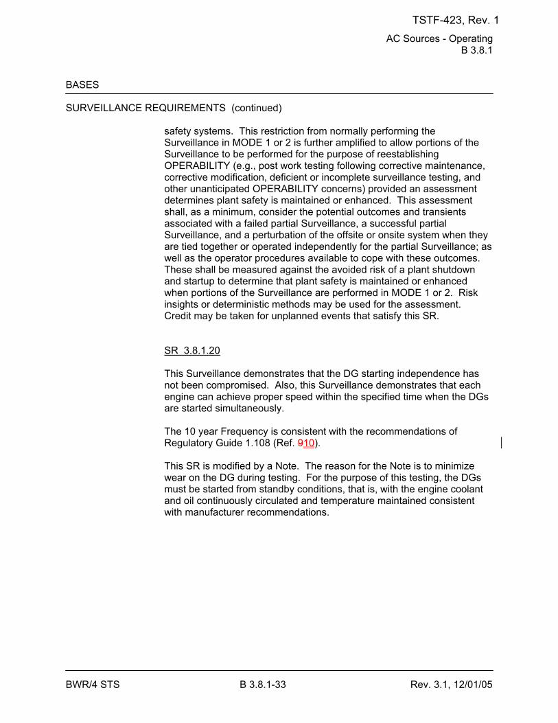
AC Sources - Operating B 3.8.1
BWR/4 STS B 3.8.1-33 Rev. 3.1, 12/01/05
BASES SURVEILLANCE REQUIREMENTS (continued)
safety systems. This restriction from normally performing the Surveillance in MODE 1 or 2 is further amplified to allow portions of the Surveillance to be performed for the purpose of reestablishing OPERABILITY (e.g., post work testing following corrective maintenance, corrective modification, deficient or incomplete surveillance testing, and other unanticipated OPERABILITY concerns) provided an assessment determines plant safety is maintained or enhanced. This assessment shall, as a minimum, consider the potential outcomes and transients associated with a failed partial Surveillance, a successful partial Surveillance, and a perturbation of the offsite or onsite system when they are tied together or operated independently for the partial Surveillance; as well as the operator procedures available to cope with these outcomes. These shall be measured against the avoided risk of a plant shutdown and startup to determine that plant safety is maintained or enhanced when portions of the Surveillance are performed in MODE 1 or 2. Risk insights or deterministic methods may be used for the assessment. Credit may be taken for unplanned events that satisfy this SR. SR 3.8.1.20 This Surveillance demonstrates that the DG starting independence has not been compromised. Also, this Surveillance demonstrates that each engine can achieve proper speed within the specified time when the DGs are started simultaneously. The 10 year Frequency is consistent with the recommendations of Regulatory Guide 1.108 (Ref. 910). This SR is modified by a Note. The reason for the Note is to minimize wear on the DG during testing. For the purpose of this testing, the DGs must be started from standby conditions, that is, with the engine coolant and oil continuously circulated and temperature maintained consistent with manufacturer recommendations.
TSTF-423, Rev. 1
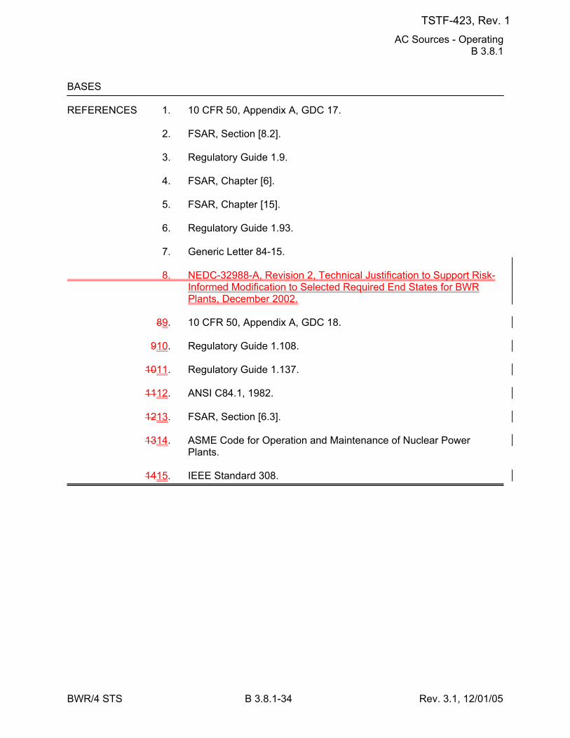
AC Sources - Operating B 3.8.1
BWR/4 STS B 3.8.1-34 Rev. 3.1, 12/01/05
BASES REFERENCES 1. 10 CFR 50, Appendix A, GDC 17. 2. FSAR, Section [8.2]. 3. Regulatory Guide 1.9. 4. FSAR, Chapter [6]. 5. FSAR, Chapter [15]. 6. Regulatory Guide 1.93. 7. Generic Letter 84-15. 8. NEDC-32988-A, Revision 2, Technical Justification to Support Risk-
Informed Modification to Selected Required End States for BWR Plants, December 2002.
89. 10 CFR 50, Appendix A, GDC 18. 910. Regulatory Guide 1.108. 1011. Regulatory Guide 1.137. 1112. ANSI C84.1, 1982. 1213. FSAR, Section [6.3]. 1314. ASME Code for Operation and Maintenance of Nuclear Power
Plants. 1415. IEEE Standard 308.
TSTF-423, Rev. 1
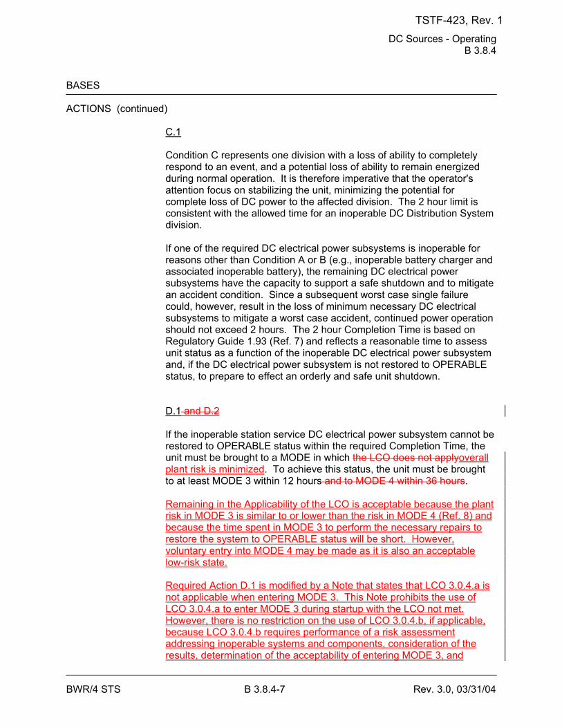
DC Sources - Operating B 3.8.4
BWR/4 STS B 3.8.4-7 Rev. 3.0, 03/31/04
BASES ACTIONS (continued)
C.1 Condition C represents one division with a loss of ability to completely respond to an event, and a potential loss of ability to remain energized during normal operation. It is therefore imperative that the operator's attention focus on stabilizing the unit, minimizing the potential for complete loss of DC power to the affected division. The 2 hour limit is consistent with the allowed time for an inoperable DC Distribution System division. If one of the required DC electrical power subsystems is inoperable for reasons other than Condition A or B (e.g., inoperable battery charger and associated inoperable battery), the remaining DC electrical power subsystems have the capacity to support a safe shutdown and to mitigate an accident condition. Since a subsequent worst case single failure could, however, result in the loss of minimum necessary DC electrical subsystems to mitigate a worst case accident, continued power operation should not exceed 2 hours. The 2 hour Completion Time is based on Regulatory Guide 1.93 (Ref. 7) and reflects a reasonable time to assess unit status as a function of the inoperable DC electrical power subsystem and, if the DC electrical power subsystem is not restored to OPERABLE status, to prepare to effect an orderly and safe unit shutdown. D.1 and D.2 If the inoperable station service DC electrical power subsystem cannot be restored to OPERABLE status within the required Completion Time, the unit must be brought to a MODE in which the LCO does not applyoverall plant risk is minimized. To achieve this status, the unit must be brought to at least MODE 3 within 12 hours and to MODE 4 within 36 hours. Remaining in the Applicability of the LCO is acceptable because the plant risk in MODE 3 is similar to or lower than the risk in MODE 4 (Ref. 8) and because the time spent in MODE 3 to perform the necessary repairs to restore the system to OPERABLE status will be short. However, voluntary entry into MODE 4 may be made as it is also an acceptable low-risk state. Required Action D.1 is modified by a Note that states that LCO 3.0.4.a is not applicable when entering MODE 3. This Note prohibits the use of LCO 3.0.4.a to enter MODE 3 during startup with the LCO not met. However, there is no restriction on the use of LCO 3.0.4.b, if applicable, because LCO 3.0.4.b requires performance of a risk assessment addressing inoperable systems and components, consideration of the results, determination of the acceptability of entering MODE 3, and
TSTF-423, Rev. 1
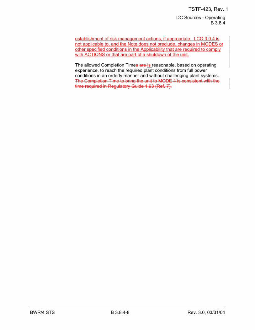
DC Sources - Operating B 3.8.4
BWR/4 STS B 3.8.4-8 Rev. 3.0, 03/31/04
establishment of risk management actions, if appropriate. LCO 3.0.4 is not applicable to, and the Note does not preclude, changes in MODES or other specified conditions in the Applicability that are required to comply with ACTIONS or that are part of a shutdown of the unit. The allowed Completion Times are is reasonable, based on operating experience, to reach the required plant conditions from full power conditions in an orderly manner and without challenging plant systems. The Completion Time to bring the unit to MODE 4 is consistent with the time required in Regulatory Guide 1.93 (Ref. 7).
TSTF-423, Rev. 1
DC Sources - Operating B 3.8.4
BWR/4 STS B 3.8.4-9 Rev. 3.0, 03/31/04
BASES ACTIONS (continued)
E.1 If the DG DC electrical power subsystem cannot be restored to OPERABLE status in the associated Completion Time, the associated DG may be incapable of performing its intended function and must be immediately declared inoperable. This declaration also requires entry into applicable Conditions and Required Actions for an inoperable DG, LCO 3.8.1, "AC Sources - Operating."
SURVEILLANCE SR 3.8.4.1 REQUIREMENTS
Verifying battery terminal voltage while on float charge helps to ensure the effectiveness of the battery chargers, which support the ability of the batteries to perform their intended function. Float charge is the condition in which the charger is supplying the continuous charge required to overcome the internal losses of a battery and maintain the battery in a fully charged state while supplying the continuous steady state loads of the associated DC subsystem. On float charge, battery cells will receive adequate current to optimally charge the battery. The voltage requirements are based on the nominal design voltage of the battery and are consistent with the minimum float voltage established by the battery manufacturer ([2.20] Vpc or [127.6] V at the battery terminals). This voltage maintains the battery plates in a condition that supports maintaining the grid life (expected to be approximately 20 years). The 7 day Frequency is consistent with manufacturer recommendations and IEEE-450 (Ref. 89). SR 3.8.4.2 This SR verifies the design capacity of the battery chargers. According to Regulatory Guide 1.32 (Ref. 910), the battery charger supply is recommended to be based on the largest combined demands of the various steady state loads and the charging capacity to restore the battery from the design minimum charge state to the fully charged state, irrespective of the status of the unit during these demand occurrences. The minimum required amperes and duration ensures that these requirements can be satisfied.
TSTF-423, Rev. 1
DC Sources - Operating B 3.8.4
BWR/4 STS B 3.8.4-10 Rev. 3.0, 03/31/04
BASES SURVEILLANCE REQUIREMENTS (continued)
This SR provides two options. One option requires that each battery charger be capable of supplying [400] amps at the minimum established float voltage for [8] hours. The ampere requirements are based on the output rating of the chargers. The voltage requirements are based on the charger voltage level after a response to a loss of AC power. The time period is sufficient for the charger temperature to have stabilized and to have been maintained for at least [2] hours. The other option requires that each battery charger be capable of recharging the battery after a service test coincident with supplying the largest coincident demands of the various continuous steady state loads (irrespective of the status of the plant during which these demands occur). This level of loading may not normally be available following the battery service test and will need to be supplemented with additional loads. The duration for this test may be longer than the charger sizing criteria since the battery recharge is affected by float voltage, temperature, and the exponential decay in charging current. The battery is recharged when the measured charging current is ≤ [2] amps. The Frequency is acceptable, given the unit conditions required to perform the test and the other administrative controls existing to ensure adequate charger performance during these [18 month] intervals. In addition, this Frequency is intended to be consistent with expected fuel cycle lengths. SR 3.8.4.3 A battery service test is a special test of the battery's capability, as found, to satisfy the design requirements (battery duty cycle) of the DC electrical power system. The discharge rate and test length corresponds to the design duty cycle requirements as specified in Reference 4. The Frequency of [18 months] is consistent with the recommendations of Regulatory Guide 1.32 (Ref. 910) and Regulatory Guide 1.129 (Ref. 1011), which state that the battery service test should be performed during refueling operations or at some other outage, with intervals between tests not to exceed [18 months]. This SR is modified by two Notes. Note 1 allows the performance of a modified performance discharge test in lieu of a service test.
TSTF-423, Rev. 1
DC Sources - Operating B 3.8.4
BWR/4 STS B 3.8.4-11 Rev. 3.0, 03/31/04
BASES SURVEILLANCE REQUIREMENTS (continued)
The reason for Note 2 is that performing the Surveillance would remove a required DC electrical power subsystem from service, perturb the electrical distribution system, and challenge safety systems. This restriction from normally performing the Surveillance in MODE 1 or 2 is further amplified to allow portions of the Surveillance to be performed for the purpose of reestablishing OPERABILITY (e.g., post work testing following corrective maintenance, corrective modification, deficient or incomplete surveillance testing, and other unanticipated OPERABILITY concerns) provided an assessment determines plant safety is maintained or enhanced. This assessment shall, as a minimum, consider the potential outcomes and transients associated with a failed partial Surveillance, a successful partial Surveillance, and a perturbation of the offsite or onsite system when they are tied together or operated independently for the partial Surveillance; as well as the operator procedures available to cope with these outcomes. These shall be measured against the avoided risk of a plant shutdown and startup to determine that plant safety is maintained or enhanced when portions of the Surveillance are performed in MODE 1 or 2. Risk insights or deterministic methods may be used for the assessment. Credit may be taken for unplanned events that satisfy this SR.
REFERENCES 1. 10 CFR 50, Appendix A, GDC 17. 2. Regulatory Guide 1.6, March 10, 1971. 3. IEEE Standard 308, 1978. 4. FSAR, Chapter [8]. 5. FSAR, Chapter [6]. 6. FSAR, Chapter [15]. 7. Regulatory Guide 1.93. 8. NEDC-32988-A, Revision 2, Technical Justification to Support Risk-
Informed Modification to Selected Required End States for BWR Plants, December 2002.
89. IEEE Standard 450, 1995. 910. Regulatory Guide 1.32, February 1977. 1011. Regulatory Guide 1.129, December 1974.
TSTF-423, Rev. 1
Inverters - Operating B 3.8.7
BWR/4 STS B 3.8.7-3 Rev. 3.0, 03/31/04
BASES APPLICABILITY The inverters are required to be OPERABLE in MODES 1, 2, and 3 to
ensure that:
a. Acceptable fuel design limits and reactor coolant pressure boundary limits are not exceeded as a result of AOOs or abnormal transients and
b. Adequate core cooling is provided, and containment OPERABILITY
and other vital functions are maintained in the event of a postulated DBA.
Inverter requirement for MODES 4 and 5 are covered in the Bases for LCO 3.8.8, "Inverters - Shutdown."
ACTIONS A.1
With a required inverter inoperable, its associated AC vital bus becomes inoperable until it is manually re-energized from its [Class 1E constant voltage source transformer or inverter using an internal AC source]. LCO 3.8.9 addresses this action; however, pursuant to LCO 3.0.6, these actions would not be entered even if the AC vital bus were de-energized. Therefore, the ACTIONS are modified by a Note to require the ACTIONS for LCO 3.8.9 be entered immediately. This ensures the vital bus is re-energized within 2 hours. Required Action A.1 allows 24 hours to fix the inoperable inverter and return it to service. The 24 hour limit is based upon engineering judgment and takes into consideration the time required to repair an inverter and the additional risk to which the unit is exposed because of the inverter inoperability. This risk has to be balanced against the risk of an immediate shutdown, along with the potential challenges to safety systems that such a shutdown might entail. When the AC vital bus is powered from its constant voltage source, it is relying upon interruptible AC electrical power sources (offsite and onsite). Similarly, the uninterruptible inverter source to the AC vital buses is the preferred source for powering instrumentation trip setpoint devices. B.1 and B.2 If the inoperable devices or components cannot be restored to OPERABLE status within the associated Completion Time, the unit must be brought to a MODE in which the LCO does not applyoverall plant risk is minimized. To achieve this status, the plant must be brought to at least MODE 3 within 12 hours and to MODE 4 within 36 hours. Remaining in the Applicability of the LCO is acceptable because the plant risk in MODE 3 is similar to or lower than the risk in MODE 4 (Ref. 4) and
TSTF-423, Rev. 1
Inverters - Operating B 3.8.7
BWR/4 STS B 3.8.7-4 Rev. 3.0, 03/31/04
because the time spent in MODE 3 to perform the necessary repairs to restore the system to OPERABLE status will be short. However, voluntary entry into MODE 4 may be made as it is also an acceptable low-risk state. Required Action B.1 is modified by a Note that states that LCO 3.0.4.a is not applicable when entering MODE 3. This Note prohibits the use of LCO 3.0.4.a to enter MODE 3 during startup with the LCO not met. However, there is no restriction on the use of LCO 3.0.4.b, if applicable, because LCO 3.0.4.b requires performance of a risk assessment addressing inoperable systems and components, consideration of the results, determination of the acceptability of entering MODE 3, and establishment of risk management actions, if appropriate. LCO 3.0.4 is not applicable to, and the Note does not preclude, changes in MODES or other specified conditions in the Applicability that are required to comply with ACTIONS or that are part of a shutdown of the unit. The allowed Completion Times are is reasonable, based on operating experience, to reach the required plant conditions from full power conditions in an orderly manner and without challenging unit systems.
TSTF-423, Rev. 1
Inverters - Operating B 3.8.7
BWR/4 STS B 3.8.7-5 Rev. 3.0, 03/31/04
BASES SURVEILLANCE SR 3.8.7.1 REQUIREMENTS
This Surveillance verifies that the inverters are functioning properly with all required circuit breakers closed and AC vital buses energized from the inverter. The verification of proper voltage and frequency output ensures that the required power is readily available for instrumentation connected to the AC vital buses. The 7 day Frequency takes into account the redundant capability of the inverters and other indications available in the control room that alert the operator to inverter malfunctions.
REFERENCES 1. FSAR, Chapter [8]. 2. FSAR, Chapter [6]. 3. FSAR, Chapter [15]. 4. NEDC-32988-A, Revision 2, Technical Justification to Support Risk-
Informed Modification to Selected Required End States for BWR Plants, December 2002.
TSTF-423, Rev. 1
Distribution Systems - Operating B 3.8.9
BWR/4 STS B 3.8.9-7 Rev. 3.1, 12/01/05
BASES ACTIONS (continued)
D.1 and D.2 If the inoperable distribution subsystem cannot be restored to OPERABLE status within the associated Completion Time, the unit must be brought to a MODE in which the LCO does not applyoverall plant risk is minimized. To achieve this status, the plant must be brought to at least MODE 3 within 12 hours and to MODE 4 within 36 hours. Remaining in the Applicability of the LCO is acceptable because the plant risk in MODE 3 is similar to or lower than the risk in MODE 4 (Ref. 4) and because the time spent in MODE 3 to perform the necessary repairs to restore the system to OPERABLE status will be short. However, voluntary entry into MODE 4 may be made as it is also an acceptable low-risk state. Required Action D.1 is modified by a Note that states that LCO 3.0.4.a is not applicable when entering MODE 3. This Note prohibits the use of LCO 3.0.4.a to enter MODE 3 during startup with the LCO not met. However, there is no restriction on the use of LCO 3.0.4.b, if applicable, because LCO 3.0.4.b requires performance of a risk assessment addressing inoperable systems and components, consideration of the results, determination of the acceptability of entering MODE 3, and establishment of risk management actions, if appropriate. LCO 3.0.4 is not applicable to, and the Note does not preclude, changes in MODES or other specified conditions in the Applicability that are required to comply with ACTIONS or that are part of a shutdown of the unit. The allowed Completion Times are is reasonable, based on operating experience, to reach the required plant conditions from full power conditions in an orderly manner and without challenging plant systems. E.1 With one or more DG DC buses inoperable, the associated DG(s) may be incapable of performing their intended functions. In this situation the DG(s) must be immediately declared inoperable. This action also requires entry into applicable Conditions and Required Actions of LCO 3.8.1, "AC Sources - Operating." F.1 Condition F corresponds to a level of degradation in the electrical distribution system that causes a required safety function to be lost. When more than one AC or DC electrical power distribution subsystem is
TSTF-423, Rev. 1
Distribution Systems - Operating B 3.8.9
BWR/4 STS B 3.8.9-9 Rev. 3.1, 12/01/05
BASES REFERENCES 1. FSAR, Chapter [6]. 2. FSAR, Chapter [15]. 3. Regulatory Guide 1.93, December 1974. 4. NEDC-32988-A, Revision 2, Technical Justification to Support Risk-
Informed Modification to Selected Required End States for BWR Plants, December 2002.
TSTF-423, Rev. 1
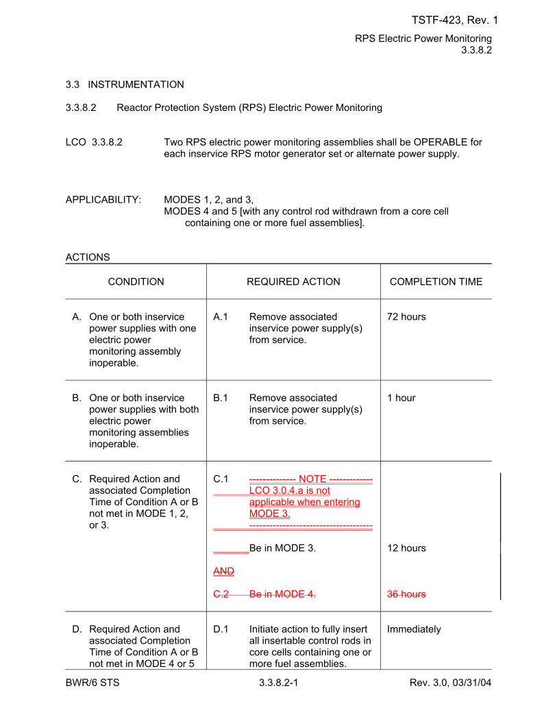
RPS Electric Power Monitoring 3.3.8.2
BWR/6 STS 3.3.8.2-1 Rev. 3.0, 03/31/04
3.3 INSTRUMENTATION 3.3.8.2 Reactor Protection System (RPS) Electric Power Monitoring LCO 3.3.8.2 Two RPS electric power monitoring assemblies shall be OPERABLE for
each inservice RPS motor generator set or alternate power supply. APPLICABILITY: MODES 1, 2, and 3, MODES 4 and 5 [with any control rod withdrawn from a core cell
containing one or more fuel assemblies]. ACTIONS
CONDITION
REQUIRED ACTION
COMPLETION TIME
A. One or both inservice
power supplies with one electric power monitoring assembly inoperable.
A.1 Remove associated
inservice power supply(s) from service.
72 hours
B. One or both inservice
power supplies with both electric power monitoring assemblies inoperable.
B.1 Remove associated
inservice power supply(s) from service.
1 hour
C. Required Action and
associated Completion Time of Condition A or B not met in MODE 1, 2, or 3.
C.1 -------------- NOTE ------------- LCO 3.0.4.a is not
applicable when entering MODE 3.
------------------------------------- Be in MODE 3. AND C.2 Be in MODE 4.
12 hours 36 hours
D. Required Action and
associated Completion Time of Condition A or B not met in MODE 4 or 5
D.1 Initiate action to fully insert
all insertable control rods in core cells containing one or more fuel assemblies.
Immediately
TSTF-423, Rev. 1
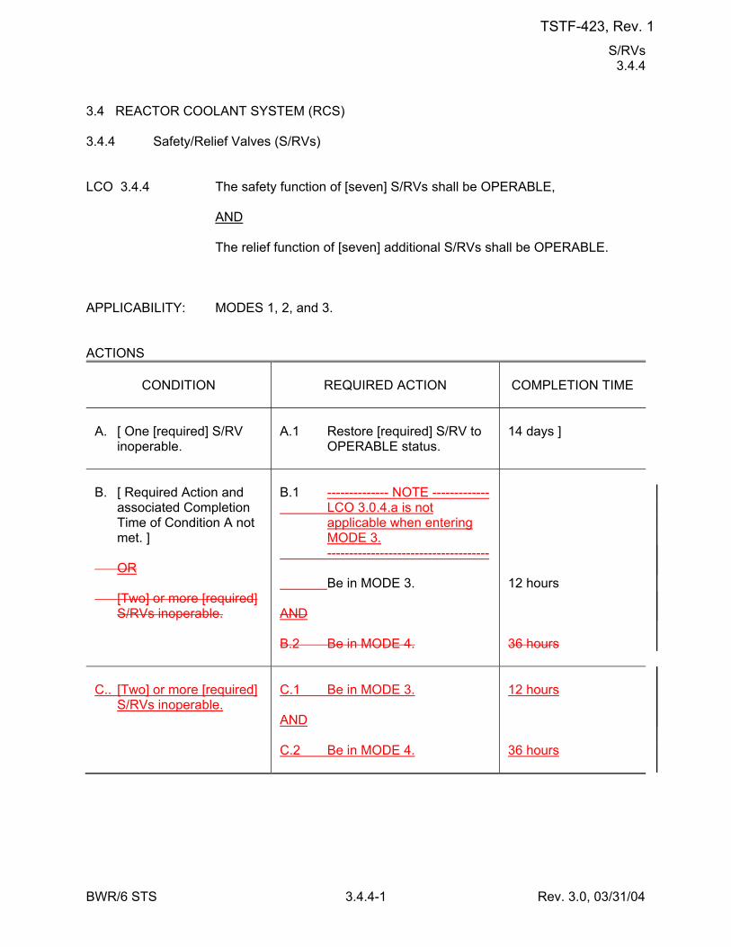
S/RVs 3.4.4
BWR/6 STS 3.4.4-1 Rev. 3.0, 03/31/04
3.4 REACTOR COOLANT SYSTEM (RCS) 3.4.4 Safety/Relief Valves (S/RVs) LCO 3.4.4 The safety function of [seven] S/RVs shall be OPERABLE, AND The relief function of [seven] additional S/RVs shall be OPERABLE. APPLICABILITY: MODES 1, 2, and 3. ACTIONS
CONDITION
REQUIRED ACTION
COMPLETION TIME
A. [ One [required] S/RV
inoperable.
A.1 Restore [required] S/RV to
OPERABLE status.
14 days ]
B. [ Required Action and
associated Completion Time of Condition A not met. ]
OR [Two] or more [required]
S/RVs inoperable.
B.1 -------------- NOTE ------------- LCO 3.0.4.a is not
applicable when entering MODE 3.
------------------------------------- Be in MODE 3. AND B.2 Be in MODE 4.
12 hours 36 hours
C.. [Two] or more [required]
S/RVs inoperable.
C.1 Be in MODE 3. AND C.2 Be in MODE 4.
12 hours 36 hours
TSTF-423, Rev. 1
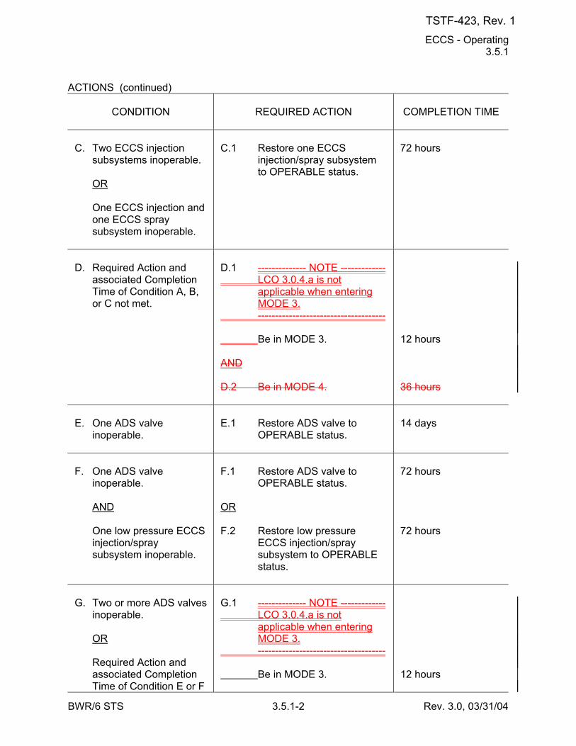
ECCS - Operating 3.5.1
BWR/6 STS 3.5.1-2 Rev. 3.0, 03/31/04
ACTIONS (continued)
CONDITION
REQUIRED ACTION
COMPLETION TIME
C. Two ECCS injection
subsystems inoperable. OR One ECCS injection and
one ECCS spray subsystem inoperable.
C.1 Restore one ECCS
injection/spray subsystem to OPERABLE status.
72 hours
D. Required Action and
associated Completion Time of Condition A, B, or C not met.
D.1 -------------- NOTE ------------- LCO 3.0.4.a is not
applicable when entering MODE 3.
------------------------------------- Be in MODE 3. AND D.2 Be in MODE 4.
12 hours 36 hours
E. One ADS valve
inoperable.
E.1 Restore ADS valve to
OPERABLE status.
14 days
F. One ADS valve
inoperable. AND One low pressure ECCS
injection/spray subsystem inoperable.
F.1 Restore ADS valve to
OPERABLE status. OR F.2 Restore low pressure
ECCS injection/spray subsystem to OPERABLE status.
72 hours 72 hours
G. Two or more ADS valves
inoperable. OR Required Action and
associated Completion Time of Condition E or F
G.1 -------------- NOTE ------------- LCO 3.0.4.a is not
applicable when entering MODE 3.
------------------------------------- Be in MODE 3.
12 hours
TSTF-423, Rev. 1
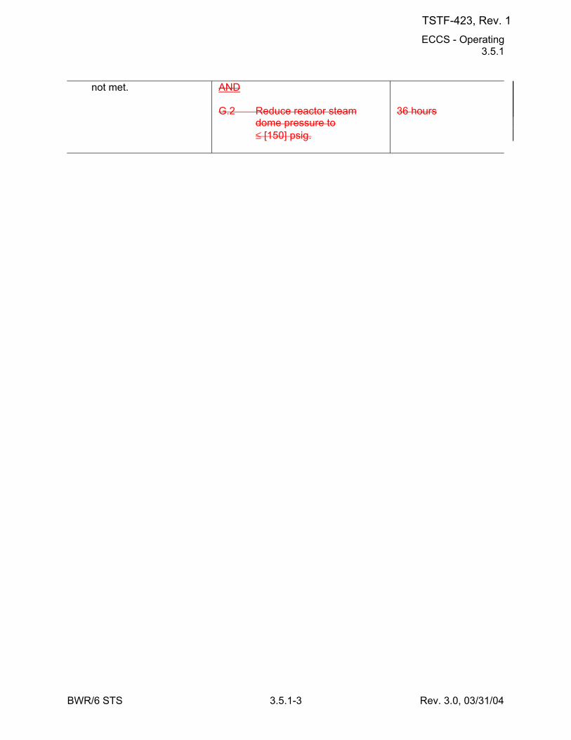
ECCS - Operating 3.5.1
BWR/6 STS 3.5.1-3 Rev. 3.0, 03/31/04
not met.
AND G.2 Reduce reactor steam
dome pressure to ≤ [150] psig.
36 hours
TSTF-423, Rev. 1
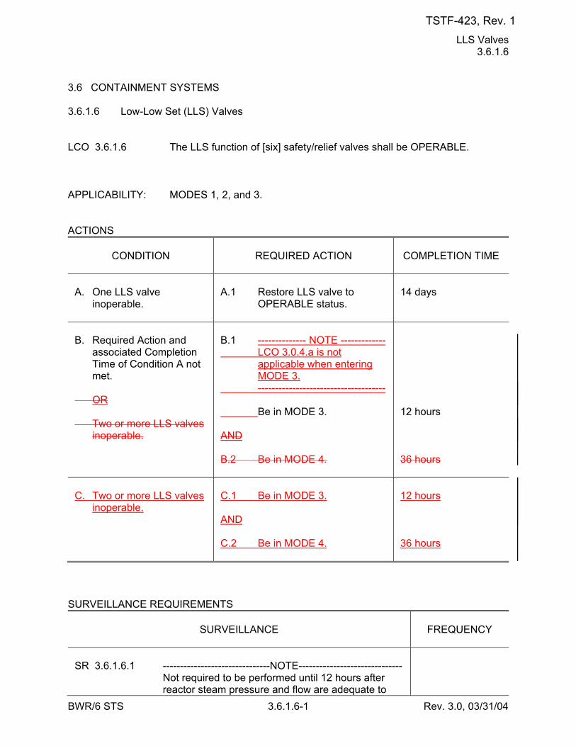
LLS Valves 3.6.1.6
BWR/6 STS 3.6.1.6-1 Rev. 3.0, 03/31/04
3.6 CONTAINMENT SYSTEMS 3.6.1.6 Low-Low Set (LLS) Valves LCO 3.6.1.6 The LLS function of [six] safety/relief valves shall be OPERABLE. APPLICABILITY: MODES 1, 2, and 3. ACTIONS
CONDITION
REQUIRED ACTION
COMPLETION TIME
A. One LLS valve
inoperable.
A.1 Restore LLS valve to
OPERABLE status.
14 days
B. Required Action and
associated Completion Time of Condition A not met.
OR Two or more LLS valves
inoperable.
B.1 -------------- NOTE ------------- LCO 3.0.4.a is not
applicable when entering MODE 3.
------------------------------------- Be in MODE 3. AND B.2 Be in MODE 4.
12 hours 36 hours
C. Two or more LLS valves
inoperable.
C.1 Be in MODE 3. AND C.2 Be in MODE 4.
12 hours 36 hours
SURVEILLANCE REQUIREMENTS
SURVEILLANCE
FREQUENCY
SR 3.6.1.6.1 -------------------------------NOTE------------------------------ Not required to be performed until 12 hours after
reactor steam pressure and flow are adequate to
TSTF-423, Rev. 1
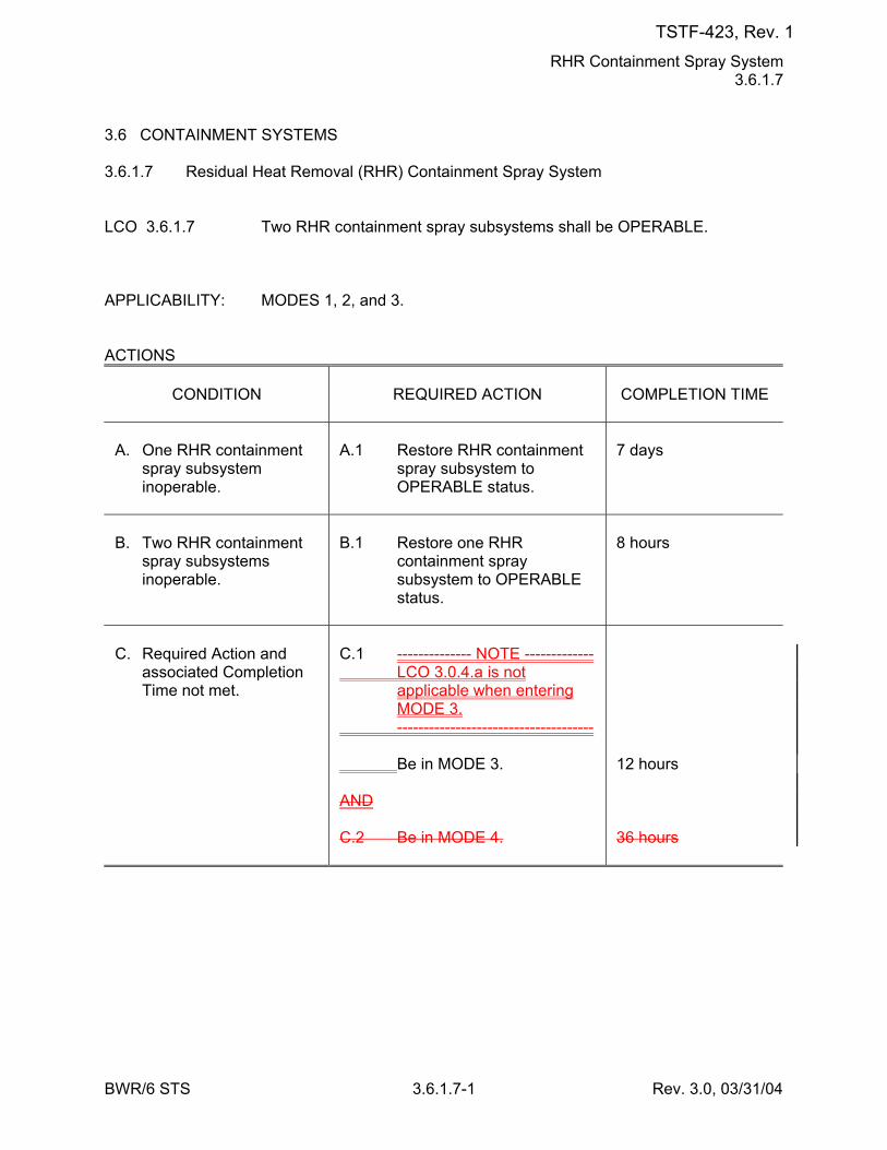
RHR Containment Spray System 3.6.1.7
BWR/6 STS 3.6.1.7-1 Rev. 3.0, 03/31/04
3.6 CONTAINMENT SYSTEMS 3.6.1.7 Residual Heat Removal (RHR) Containment Spray System LCO 3.6.1.7 Two RHR containment spray subsystems shall be OPERABLE. APPLICABILITY: MODES 1, 2, and 3. ACTIONS
CONDITION
REQUIRED ACTION
COMPLETION TIME
A. One RHR containment
spray subsystem inoperable.
A.1 Restore RHR containment
spray subsystem to OPERABLE status.
7 days
B. Two RHR containment
spray subsystems inoperable.
B.1 Restore one RHR
containment spray subsystem to OPERABLE status.
8 hours
C. Required Action and
associated Completion Time not met.
C.1 -------------- NOTE ------------- LCO 3.0.4.a is not
applicable when entering MODE 3.
------------------------------------- Be in MODE 3. AND C.2 Be in MODE 4.
12 hours 36 hours
TSTF-423, Rev. 1
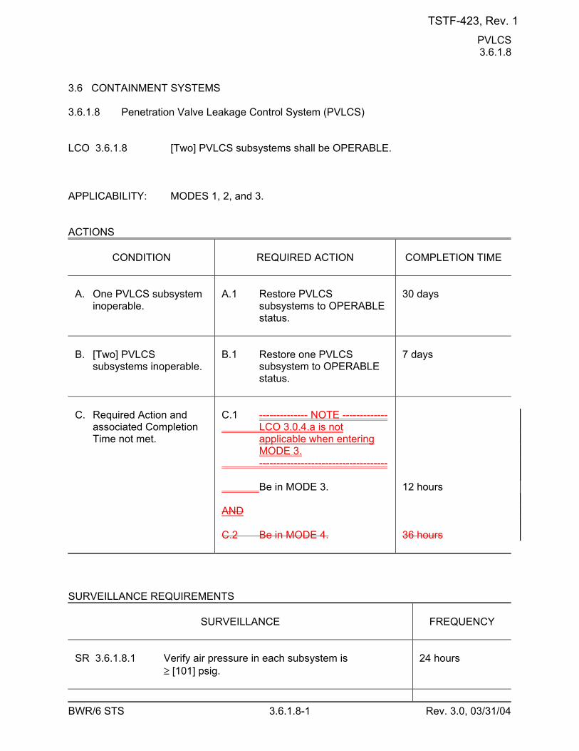
PVLCS 3.6.1.8
BWR/6 STS 3.6.1.8-1 Rev. 3.0, 03/31/04
3.6 CONTAINMENT SYSTEMS 3.6.1.8 Penetration Valve Leakage Control System (PVLCS) LCO 3.6.1.8 [Two] PVLCS subsystems shall be OPERABLE. APPLICABILITY: MODES 1, 2, and 3. ACTIONS
CONDITION
REQUIRED ACTION
COMPLETION TIME
A. One PVLCS subsystem
inoperable.
A.1 Restore PVLCS
subsystems to OPERABLE status.
30 days
B. [Two] PVLCS
subsystems inoperable.
B.1 Restore one PVLCS
subsystem to OPERABLE status.
7 days
C. Required Action and
associated Completion Time not met.
C.1 -------------- NOTE ------------- LCO 3.0.4.a is not
applicable when entering MODE 3.
------------------------------------- Be in MODE 3. AND C.2 Be in MODE 4.
12 hours 36 hours
SURVEILLANCE REQUIREMENTS
SURVEILLANCE
FREQUENCY
SR 3.6.1.8.1 Verify air pressure in each subsystem is
≥ [101] psig.
24 hours
TSTF-423, Rev. 1
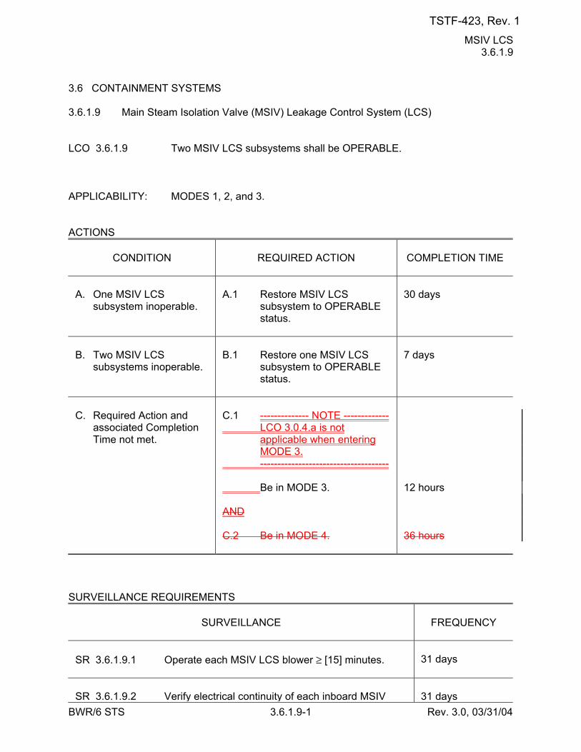
MSIV LCS 3.6.1.9
BWR/6 STS 3.6.1.9-1 Rev. 3.0, 03/31/04
3.6 CONTAINMENT SYSTEMS 3.6.1.9 Main Steam Isolation Valve (MSIV) Leakage Control System (LCS) LCO 3.6.1.9 Two MSIV LCS subsystems shall be OPERABLE. APPLICABILITY: MODES 1, 2, and 3. ACTIONS
CONDITION
REQUIRED ACTION
COMPLETION TIME
A. One MSIV LCS
subsystem inoperable.
A.1 Restore MSIV LCS
subsystem to OPERABLE status.
30 days
B. Two MSIV LCS
subsystems inoperable.
B.1 Restore one MSIV LCS
subsystem to OPERABLE status.
7 days
C. Required Action and
associated Completion Time not met.
C.1 -------------- NOTE ------------- LCO 3.0.4.a is not
applicable when entering MODE 3.
------------------------------------- Be in MODE 3. AND C.2 Be in MODE 4.
12 hours 36 hours
SURVEILLANCE REQUIREMENTS
SURVEILLANCE
FREQUENCY
SR 3.6.1.9.1 Operate each MSIV LCS blower ≥ [15] minutes.
31 days
SR 3.6.1.9.2 Verify electrical continuity of each inboard MSIV
31 days
TSTF-423, Rev. 1
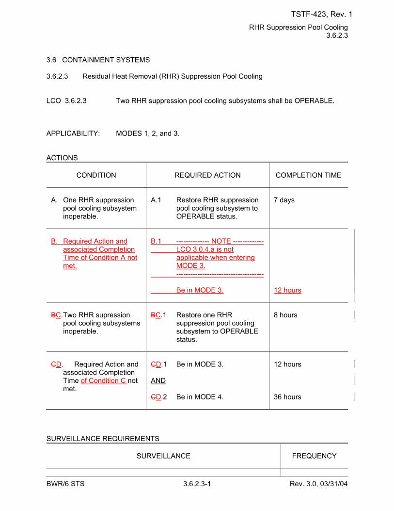
RHR Suppression Pool Cooling 3.6.2.3
BWR/6 STS 3.6.2.3-1 Rev. 3.0, 03/31/04
3.6 CONTAINMENT SYSTEMS 3.6.2.3 Residual Heat Removal (RHR) Suppression Pool Cooling LCO 3.6.2.3 Two RHR suppression pool cooling subsystems shall be OPERABLE. APPLICABILITY: MODES 1, 2, and 3. ACTIONS
CONDITION
REQUIRED ACTION
COMPLETION TIME
A. One RHR suppression
pool cooling subsystem inoperable.
A.1 Restore RHR suppression
pool cooling subsystem to OPERABLE status.
7 days
B. Required Action and
associated Completion Time of Condition A not met.
B.1 -------------- NOTE ------------- LCO 3.0.4.a is not
applicable when entering MODE 3.
------------------------------------- Be in MODE 3.
12 hours
BC. Two RHR supression
pool cooling subsystems inoperable.
BC.1 Restore one RHR
suppression pool cooling subsystem to OPERABLE status.
8 hours
CD. Required Action and
associated Completion Time of Condition C not met.
CD.1 Be in MODE 3. AND CD.2 Be in MODE 4.
12 hours 36 hours
SURVEILLANCE REQUIREMENTS
SURVEILLANCE
FREQUENCY
TSTF-423, Rev. 1
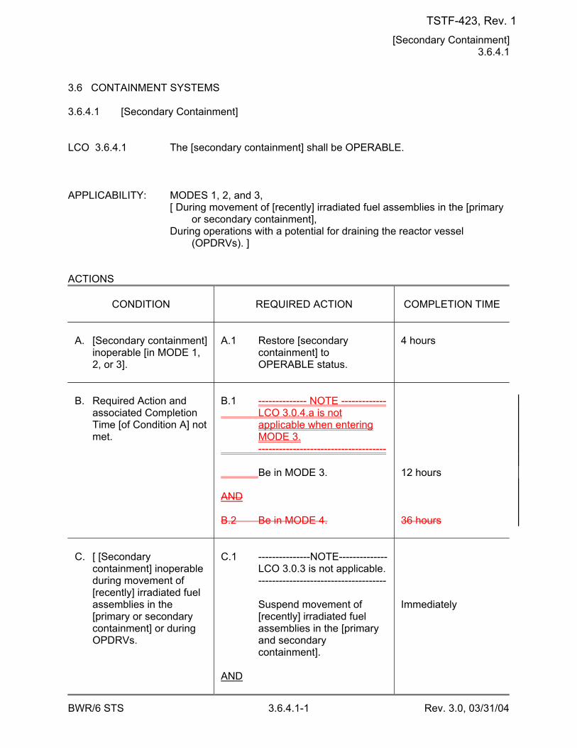
[Secondary Containment] 3.6.4.1
BWR/6 STS 3.6.4.1-1 Rev. 3.0, 03/31/04
3.6 CONTAINMENT SYSTEMS 3.6.4.1 [Secondary Containment] LCO 3.6.4.1 The [secondary containment] shall be OPERABLE. APPLICABILITY: MODES 1, 2, and 3, [ During movement of [recently] irradiated fuel assemblies in the [primary
or secondary containment], During operations with a potential for draining the reactor vessel
(OPDRVs). ] ACTIONS
CONDITION
REQUIRED ACTION
COMPLETION TIME
A. [Secondary containment]
inoperable [in MODE 1, 2, or 3].
A.1 Restore [secondary
containment] to OPERABLE status.
4 hours
B. Required Action and
associated Completion Time [of Condition A] not met.
B.1 -------------- NOTE ------------- LCO 3.0.4.a is not
applicable when entering MODE 3.
------------------------------------- Be in MODE 3. AND B.2 Be in MODE 4.
12 hours 36 hours
C. [ [Secondary
containment] inoperable during movement of [recently] irradiated fuel assemblies in the [primary or secondary containment] or during OPDRVs.
C.1 ---------------NOTE-------------- LCO 3.0.3 is not applicable. ------------------------------------- Suspend movement of
[recently] irradiated fuel assemblies in the [primary and secondary containment].
AND
Immediately
TSTF-423, Rev. 1
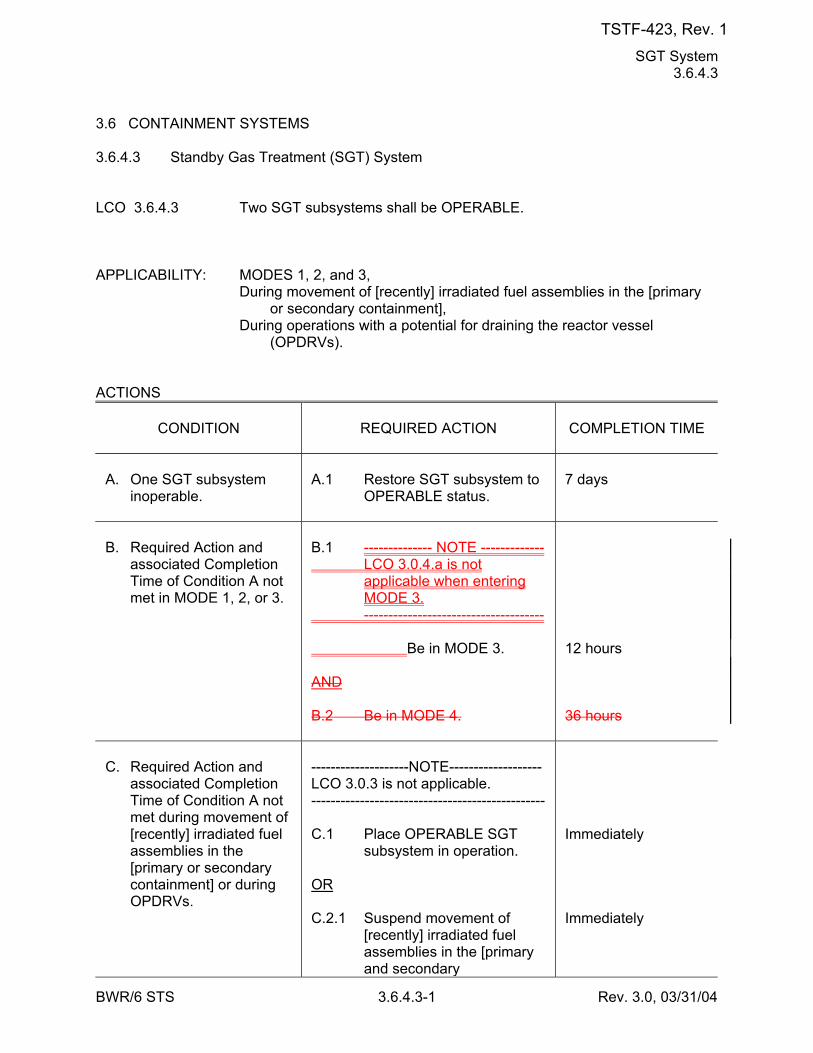
SGT System 3.6.4.3
BWR/6 STS 3.6.4.3-1 Rev. 3.0, 03/31/04
3.6 CONTAINMENT SYSTEMS 3.6.4.3 Standby Gas Treatment (SGT) System LCO 3.6.4.3 Two SGT subsystems shall be OPERABLE. APPLICABILITY: MODES 1, 2, and 3, During movement of [recently] irradiated fuel assemblies in the [primary
or secondary containment], During operations with a potential for draining the reactor vessel
(OPDRVs). ACTIONS
CONDITION
REQUIRED ACTION
COMPLETION TIME
A. One SGT subsystem
inoperable.
A.1 Restore SGT subsystem to
OPERABLE status.
7 days
B. Required Action and
associated Completion Time of Condition A not met in MODE 1, 2, or 3.
B.1 -------------- NOTE ------------- LCO 3.0.4.a is not
applicable when entering MODE 3.
------------------------------------- Be in MODE 3. AND B.2 Be in MODE 4.
12 hours 36 hours
C. Required Action and
associated Completion Time of Condition A not met during movement of [recently] irradiated fuel assemblies in the [primary or secondary containment] or during OPDRVs.
--------------------NOTE------------------- LCO 3.0.3 is not applicable. ------------------------------------------------ C.1 Place OPERABLE SGT
subsystem in operation. OR C.2.1 Suspend movement of
[recently] irradiated fuel assemblies in the [primary and secondary
Immediately Immediately
TSTF-423, Rev. 1
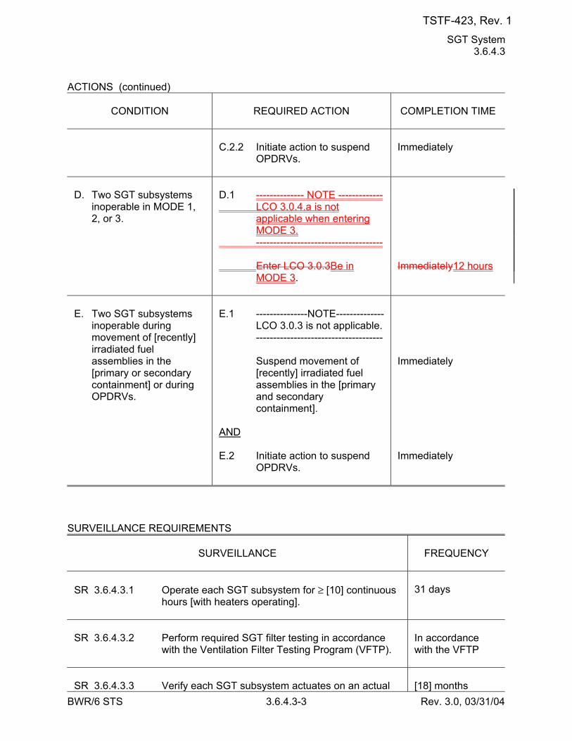
SGT System 3.6.4.3
BWR/6 STS 3.6.4.3-3 Rev. 3.0, 03/31/04
ACTIONS (continued)
CONDITION
REQUIRED ACTION
COMPLETION TIME
C.2.2 Initiate action to suspend
OPDRVs.
Immediately
D. Two SGT subsystems
inoperable in MODE 1, 2, or 3.
D.1 -------------- NOTE ------------- LCO 3.0.4.a is not
applicable when entering MODE 3.
------------------------------------- Enter LCO 3.0.3Be in
MODE 3.
Immediately12 hours
E. Two SGT subsystems
inoperable during movement of [recently] irradiated fuel assemblies in the [primary or secondary containment] or during OPDRVs.
E.1 ---------------NOTE-------------- LCO 3.0.3 is not applicable. ------------------------------------- Suspend movement of
[recently] irradiated fuel assemblies in the [primary and secondary containment].
AND E.2 Initiate action to suspend
OPDRVs.
Immediately Immediately
SURVEILLANCE REQUIREMENTS
SURVEILLANCE
FREQUENCY
SR 3.6.4.3.1 Operate each SGT subsystem for ≥ [10] continuous
hours [with heaters operating].
31 days
SR 3.6.4.3.2 Perform required SGT filter testing in accordance
with the Ventilation Filter Testing Program (VFTP).
In accordance with the VFTP
SR 3.6.4.3.3 Verify each SGT subsystem actuates on an actual
[18] months
TSTF-423, Rev. 1
Drywell Vacuum Relief System 3.6.5.6
BWR/6 STS 3.6.5.6-2 Rev. 3.0, 03/31/04
ACTIONS (continued)
CONDITION
REQUIRED ACTION
COMPLETION TIME
D. Required Action and
associated Completion Time of Condition B or C not met.
D.1 -------------- NOTE ------------- LCO 3.0.4.a is not
applicable when entering MODE 3.
------------------------------------- Be in MODE 3.
12 hours
DE. [Two] drywell purge
vacuum relief subsystems inoperable for reasons other than Condition A.
DE.1 Restore one drywell purge
vacuum relief subsystem to OPERABLE status.
72 hours
EF. [Two] drywell post-LOCA
vacuum relief subsystems inoperable for reasons other than Condition A.
AND One drywell purge
vacuum relief subsystem inoperable for reasons other than Condition A.
EF.1 Restore one drywell post-
LOCA vacuum relief or drywell purge vacuum relief subsystem to OPERABLE status.
72 hours
FG. Required Action and
associated Completion Time of Condition A, B, C, D, or E or F not met.
FG.1 Be in MODE 3. AND FG.2 Be in MODE 4.
12 hours 36 hours
GH. [Two] drywell purge
vacuum relief subsystems inoperable for reasons other than Condition A.
AND One or [two] drywell
GH.1 Be in MODE 3. AND GH.2 Be in MODE 4.
12 hours 36 hours
TSTF-423, Rev. 1
[SSW] System and [UHS] 3.7.1
BWR/6 STS 3.7.1-1 Rev. 3.0, 03/31/04
3.7 PLANT SYSTEMS 3.7.1 [Standby Service Water (SSW)] System and [Ultimate Heat Sink (UHS)] LCO 3.7.1 Division 1 and 2 [SSW] subsystems and [UHS] shall be OPERABLE. APPLICABILITY: MODES 1, 2, and 3. ACTIONS
CONDITION
REQUIRED ACTION
COMPLETION TIME
A. [ One or more cooling
towers with one cooling tower fan inoperable.
A.1 Restore cooling tower
fan(s) to OPERABLE status.
7 days ]
B. One [SSW] subsystem
inoperable [for reasons other than Condition A].
B.1 --------------NOTES------------- 1. Enter applicable
Conditions and Required Actions of LCO 3.8.1, "AC Sources - Operating," for diesel generator made inoperable by [SSW].
2. Enter applicable
Conditions and Required Actions of LCO 3.4.9, "Residual Heat Removal (RHR) Shutdown Cooling System - Hot Shutdown," for [RHR shutdown cooling] made inoperable by [SSW].
------------------------------------- Restore [SSW] subsystem
to OPERABLE status.
72 hours
TSTF-423, Rev. 1
[SSW] System and [UHS] 3.7.1
BWR/6 STS 3.7.1-2 Rev. 3.0, 03/31/04
CONDITION
REQUIRED ACTION
COMPLETION TIME
C. Required Action and
associated Completion Time of Condition A or B not met.
C.1 -------------- NOTE ------------- LCO 3.0.4.a is not
applicable when entering MODE 3.
------------------------------------- Be in MODE 3.
12 hours
-----REVIEWER’S NOTE----- The [ ]°F is the maximum allowed UHS temperature value and is based on temperature limitations of the equipment that is relied upon for accident mitigation and safe shutdown of the unit. -------------------------------------- BD. [ Water temperature of
the UHS > [90]°F and ≤ [ ]°F.
BD.1 Verify water temperature of
the UHS is ≤ [90]°F averaged over the previous 24 hour period.
Once per hour ]
TSTF-423, Rev. 1
[SSW] System and [UHS] 3.7.1
BWR/6 STS 3.7.1-3 Rev. 3.0, 03/31/04
ACTIONS (continued)
CONDITION
REQUIRED ACTION
COMPLETION TIME
C. One [SSW] subsystem
inoperable [for reasons other than Condition A].
C.1 --------------NOTES------------- 1. Enter applicable
Conditions and Required Actions of LCO 3.8.1, "AC Sources - Operating," for diesel generator made inoperable by [SSW].
2. Enter applicable
Conditions and Required Actions of LCO 3.4.9, "Residual Heat Removal (RHR) Shutdown Cooling System - Hot Shutdown," for [RHR shutdown cooling] made inoperable by [SSW].
------------------------------------- Restore [SSW] subsystem
to OPERABLE status.
72 hours
DE. Required Action and
associated Completion Time of Condition A, [B] or CD not met.
OR Both [SSW] subsystems
inoperable [for reasons other than Condition A].
[ OR [UHS] inoperable for
reasons other than Condition A [or BD]. ]
DE.1 Be in MODE 3. AND DE.2 Be in MODE 4.
12 hours 36 hours
TSTF-423, Rev. 1
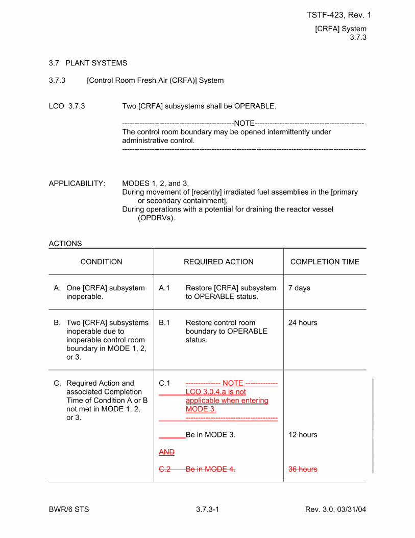
[CRFA] System 3.7.3
BWR/6 STS 3.7.3-1 Rev. 3.0, 03/31/04
3.7 PLANT SYSTEMS 3.7.3 [Control Room Fresh Air (CRFA)] System LCO 3.7.3 Two [CRFA] subsystems shall be OPERABLE. ---------------------------------------------NOTE-------------------------------------------- The control room boundary may be opened intermittently under
administrative control. -------------------------------------------------------------------------------------------------- APPLICABILITY: MODES 1, 2, and 3, During movement of [recently] irradiated fuel assemblies in the [primary
or secondary containment], During operations with a potential for draining the reactor vessel
(OPDRVs). ACTIONS
CONDITION
REQUIRED ACTION
COMPLETION TIME
A. One [CRFA] subsystem
inoperable.
A.1 Restore [CRFA] subsystem
to OPERABLE status.
7 days
B. Two [CRFA] subsystems
inoperable due to inoperable control room boundary in MODE 1, 2, or 3.
B.1 Restore control room
boundary to OPERABLE status.
24 hours
C. Required Action and
associated Completion Time of Condition A or B not met in MODE 1, 2, or 3.
C.1 -------------- NOTE ------------- LCO 3.0.4.a is not
applicable when entering MODE 3.
------------------------------------- Be in MODE 3. AND C.2 Be in MODE 4.
12 hours 36 hours
TSTF-423, Rev. 1
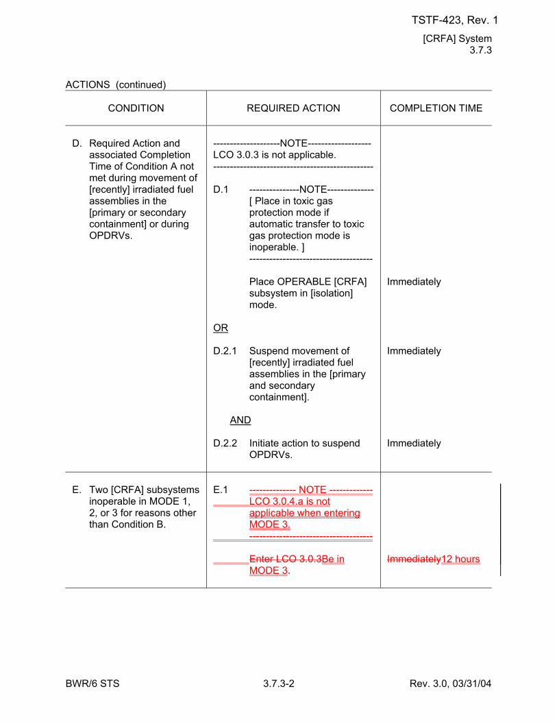
[CRFA] System 3.7.3
BWR/6 STS 3.7.3-2 Rev. 3.0, 03/31/04
ACTIONS (continued)
CONDITION
REQUIRED ACTION
COMPLETION TIME
D. Required Action and
associated Completion Time of Condition A not met during movement of [recently] irradiated fuel assemblies in the [primary or secondary containment] or during OPDRVs.
--------------------NOTE------------------- LCO 3.0.3 is not applicable. ------------------------------------------------ D.1 ---------------NOTE-------------- [ Place in toxic gas
protection mode if automatic transfer to toxic gas protection mode is inoperable. ]
------------------------------------- Place OPERABLE [CRFA]
subsystem in [isolation] mode.
OR D.2.1 Suspend movement of
[recently] irradiated fuel assemblies in the [primary and secondary containment].
AND D.2.2 Initiate action to suspend
OPDRVs.
Immediately Immediately Immediately
E. Two [CRFA] subsystems
inoperable in MODE 1, 2, or 3 for reasons other than Condition B.
E.1 -------------- NOTE ------------- LCO 3.0.4.a is not
applicable when entering MODE 3.
------------------------------------- Enter LCO 3.0.3Be in
MODE 3.
Immediately12 hours
TSTF-423, Rev. 1
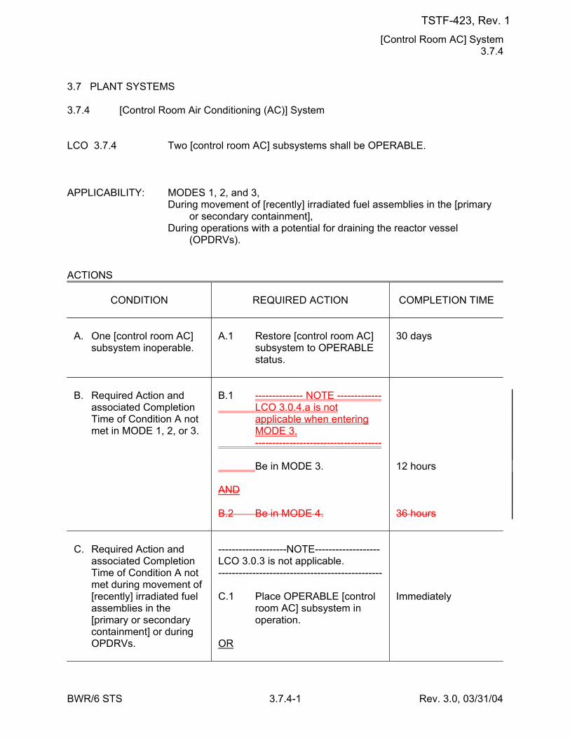
[Control Room AC] System 3.7.4
BWR/6 STS 3.7.4-1 Rev. 3.0, 03/31/04
3.7 PLANT SYSTEMS 3.7.4 [Control Room Air Conditioning (AC)] System LCO 3.7.4 Two [control room AC] subsystems shall be OPERABLE. APPLICABILITY: MODES 1, 2, and 3, During movement of [recently] irradiated fuel assemblies in the [primary
or secondary containment], During operations with a potential for draining the reactor vessel
(OPDRVs). ACTIONS
CONDITION
REQUIRED ACTION
COMPLETION TIME
A. One [control room AC]
subsystem inoperable.
A.1 Restore [control room AC]
subsystem to OPERABLE status.
30 days
B. Required Action and
associated Completion Time of Condition A not met in MODE 1, 2, or 3.
B.1 -------------- NOTE ------------- LCO 3.0.4.a is not
applicable when entering MODE 3.
------------------------------------- Be in MODE 3. AND B.2 Be in MODE 4.
12 hours 36 hours
C. Required Action and
associated Completion Time of Condition A not met during movement of [recently] irradiated fuel assemblies in the [primary or secondary containment] or during OPDRVs.
--------------------NOTE------------------- LCO 3.0.3 is not applicable. ------------------------------------------------ C.1 Place OPERABLE [control
room AC] subsystem in operation.
OR
Immediately
TSTF-423, Rev. 1
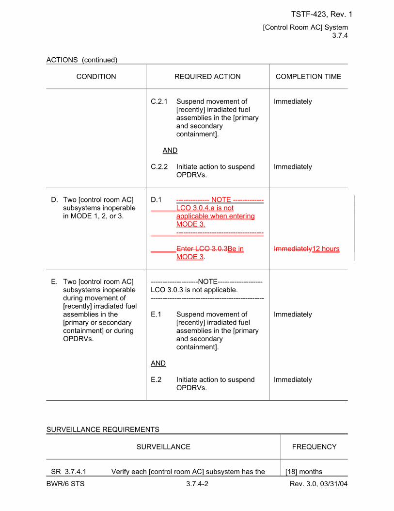
[Control Room AC] System 3.7.4
BWR/6 STS 3.7.4-2 Rev. 3.0, 03/31/04
ACTIONS (continued)
CONDITION
REQUIRED ACTION
COMPLETION TIME
C.2.1 Suspend movement of
[recently] irradiated fuel assemblies in the [primary and secondary containment].
AND C.2.2 Initiate action to suspend
OPDRVs.
Immediately Immediately
D. Two [control room AC]
subsystems inoperable in MODE 1, 2, or 3.
D.1 -------------- NOTE ------------- LCO 3.0.4.a is not
applicable when entering MODE 3.
------------------------------------- Enter LCO 3.0.3Be in
MODE 3.
Immediately12 hours
E. Two [control room AC]
subsystems inoperable during movement of [recently] irradiated fuel assemblies in the [primary or secondary containment] or during OPDRVs.
--------------------NOTE------------------- LCO 3.0.3 is not applicable. ------------------------------------------------ E.1 Suspend movement of
[recently] irradiated fuel assemblies in the [primary and secondary containment].
AND E.2 Initiate action to suspend
OPDRVs.
Immediately Immediately
SURVEILLANCE REQUIREMENTS
SURVEILLANCE
FREQUENCY
SR 3.7.4.1 Verify each [control room AC] subsystem has the
[18] months
TSTF-423, Rev. 1

Main Condenser Offgas 3.7.5
BWR/6 STS 3.7.5-1 Rev. 3.0, 03/31/04
3.7 PLANT SYSTEMS 3.7.5 Main Condenser Offgas LCO 3.7.5 The gross gamma activity rate of the noble gases measured at [the offgas
recombiner effluent] shall be ≤ [380] mCi/second [after decay of 30 minutes].
APPLICABILITY: MODE 1, MODES 2 and 3 with any [main steam line not isolated and] steam jet air
ejector (SJAE) in operation. ACTIONS
CONDITION
REQUIRED ACTION
COMPLETION TIME
A. Gross gamma activity
rate of the noble gases not within limit.
A.1 Restore gross gamma
activity rate of the noble gases to within limit.
72 hours
B. Required Action and
associated Completion Time not met.
B.1 [ Isolate all main steam
lines. OR B.2 Isolate SJAE. OR B.3.1 -------------- NOTE ------------- LCO 3.0.4.a is not
applicable when entering MODE 3.
------------------------------------- Be in MODE 3. AND B.3.2 Be in MODE 4.
12 hours ] 12 hours 12 hours 36 hours
TSTF-423, Rev. 1
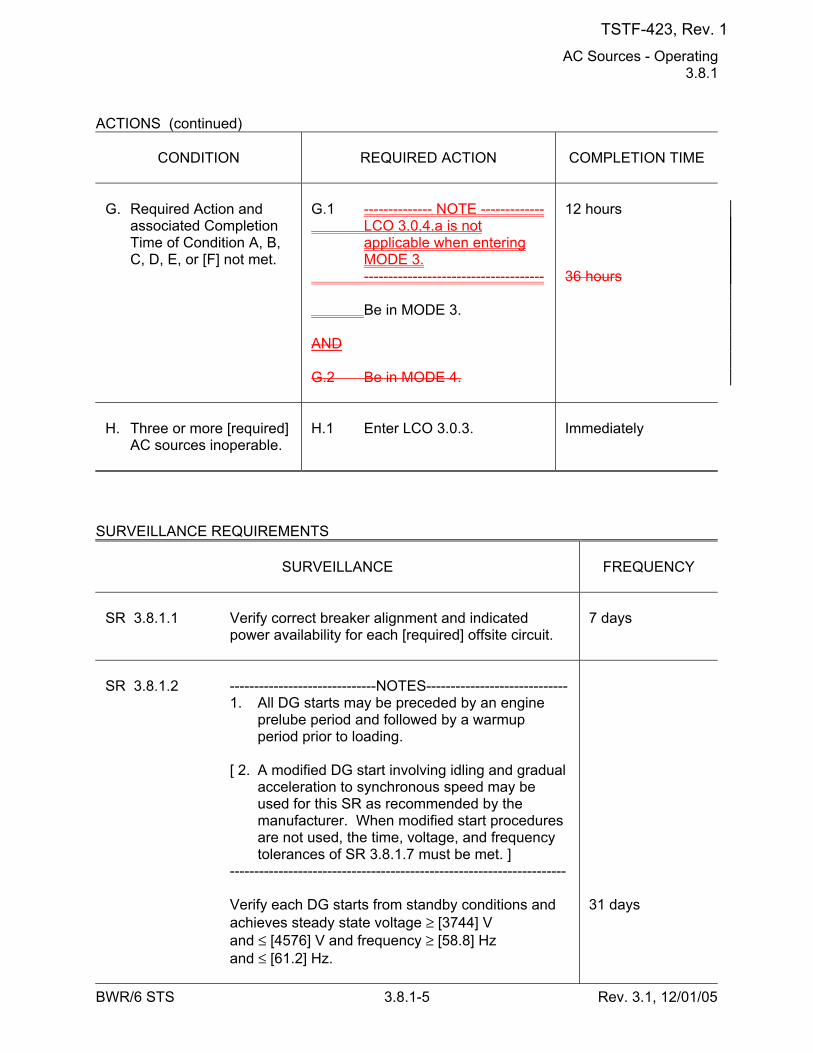
AC Sources - Operating 3.8.1
BWR/6 STS 3.8.1-5 Rev. 3.1, 12/01/05
ACTIONS (continued)
CONDITION
REQUIRED ACTION
COMPLETION TIME
G. Required Action and
associated Completion Time of Condition A, B, C, D, E, or [F] not met.
G.1 -------------- NOTE ------------- LCO 3.0.4.a is not
applicable when entering MODE 3.
------------------------------------- Be in MODE 3. AND G.2 Be in MODE 4.
12 hours 36 hours
H. Three or more [required]
AC sources inoperable.
H.1 Enter LCO 3.0.3.
Immediately
SURVEILLANCE REQUIREMENTS
SURVEILLANCE
FREQUENCY
SR 3.8.1.1 Verify correct breaker alignment and indicated
power availability for each [required] offsite circuit.
7 days
SR 3.8.1.2 ------------------------------NOTES----------------------------- 1. All DG starts may be preceded by an engine
prelube period and followed by a warmup period prior to loading.
[ 2. A modified DG start involving idling and gradual
acceleration to synchronous speed may be used for this SR as recommended by the manufacturer. When modified start procedures are not used, the time, voltage, and frequency tolerances of SR 3.8.1.7 must be met. ]
--------------------------------------------------------------------- Verify each DG starts from standby conditions and
achieves steady state voltage ≥ [3744] V and ≤ [4576] V and frequency ≥ [58.8] Hz and ≤ [61.2] Hz.
31 days
TSTF-423, Rev. 1
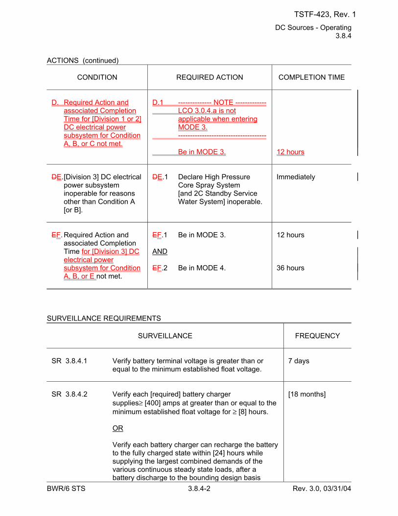
DC Sources - Operating 3.8.4
BWR/6 STS 3.8.4-2 Rev. 3.0, 03/31/04
ACTIONS (continued)
CONDITION
REQUIRED ACTION
COMPLETION TIME
D. Required Action and
associated Completion Time for [Division 1 or 2] DC electrical power subsystem for Condition A, B, or C not met.
D.1 -------------- NOTE ------------- LCO 3.0.4.a is not
applicable when entering MODE 3.
------------------------------------- Be in MODE 3.
12 hours
DE. [Division 3] DC electrical
power subsystem inoperable for reasons other than Condition A [or B].
DE.1 Declare High Pressure
Core Spray System [and 2C Standby Service Water System] inoperable.
Immediately
EF. Required Action and
associated Completion Time for [Division 3] DC electrical power subsystem for Condition A, B, or E not met.
EF.1 Be in MODE 3. AND EF.2 Be in MODE 4.
12 hours 36 hours
SURVEILLANCE REQUIREMENTS
SURVEILLANCE
FREQUENCY
SR 3.8.4.1 Verify battery terminal voltage is greater than or
equal to the minimum established float voltage.
7 days
SR 3.8.4.2 Verify each [required] battery charger
supplies≥ [400] amps at greater than or equal to the minimum established float voltage for ≥ [8] hours.
OR Verify each battery charger can recharge the battery
to the fully charged state within [24] hours while supplying the largest combined demands of the various continuous steady state loads, after a battery discharge to the bounding design basis
[18 months]
TSTF-423, Rev. 1
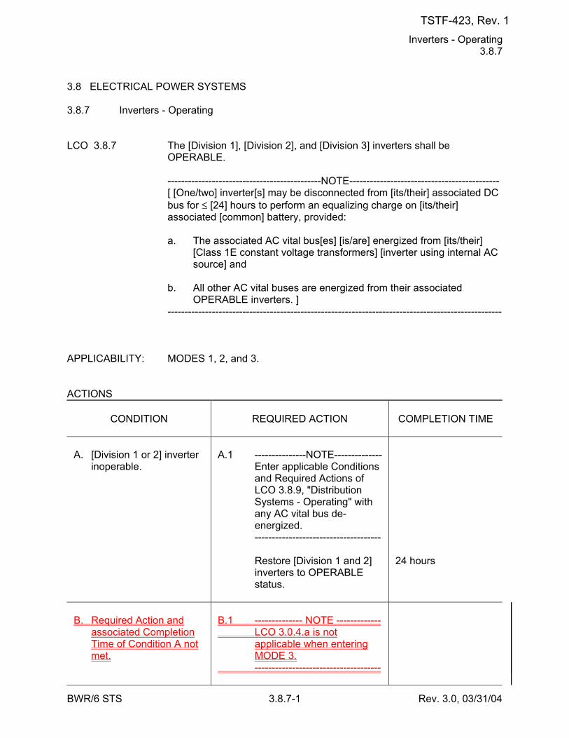
Inverters - Operating 3.8.7
BWR/6 STS 3.8.7-1 Rev. 3.0, 03/31/04
3.8 ELECTRICAL POWER SYSTEMS 3.8.7 Inverters - Operating LCO 3.8.7 The [Division 1], [Division 2], and [Division 3] inverters shall be
OPERABLE. ---------------------------------------------NOTE-------------------------------------------- [ [One/two] inverter[s] may be disconnected from [its/their] associated DC
bus for ≤ [24] hours to perform an equalizing charge on [its/their] associated [common] battery, provided:
a. The associated AC vital bus[es] [is/are] energized from [its/their]
[Class 1E constant voltage transformers] [inverter using internal AC source] and
b. All other AC vital buses are energized from their associated
OPERABLE inverters. ] -------------------------------------------------------------------------------------------------- APPLICABILITY: MODES 1, 2, and 3. ACTIONS
CONDITION
REQUIRED ACTION
COMPLETION TIME
A. [Division 1 or 2] inverter
inoperable.
A.1 ---------------NOTE-------------- Enter applicable Conditions
and Required Actions of LCO 3.8.9, "Distribution Systems - Operating" with any AC vital bus de-energized.
------------------------------------- Restore [Division 1 and 2]
inverters to OPERABLE status.
24 hours
B. Required Action and
associated Completion Time of Condition A not met.
B.1 -------------- NOTE ------------- LCO 3.0.4.a is not
applicable when entering MODE 3.
-------------------------------------
TSTF-423, Rev. 1
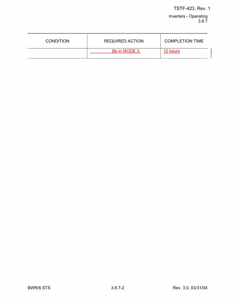
Inverters - Operating 3.8.7
BWR/6 STS 3.8.7-2 Rev. 3.0, 03/31/04
CONDITION
REQUIRED ACTION
COMPLETION TIME
Be in MODE 3. 12 hours
TSTF-423, Rev. 1
Inverters - Operating 3.8.7
BWR/6 STS 3.8.7-3 Rev. 3.0, 03/31/04
ACTIONS (continued)
CONDITION
REQUIRED ACTION
COMPLETION TIME
BC. [ [Division 3] inverter
inoperable.
BC.1 Declare High Pressure
Core Spray System [and 2C Standby Service Water System] inoperable.
Immediately ]
CD. Required Action and
associated Completion Time of Condition C not met.
CD.1 Be in MODE 3. AND CD.2 Be in MODE 4.
12 hours 36 hours
SURVEILLANCE REQUIREMENTS
SURVEILLANCE
FREQUENCY
SR 3.8.7.1 Verify correct inverter voltage, [frequency,] and
alignment to required AC vital buses.
7 days
TSTF-423, Rev. 1
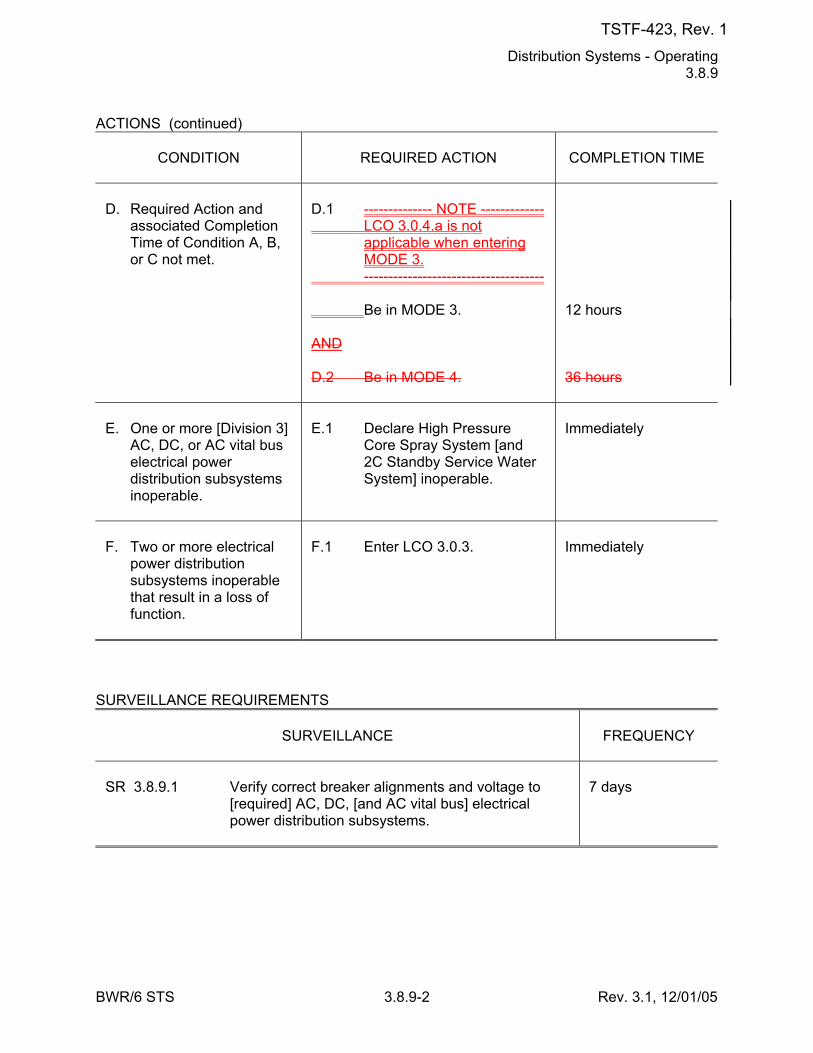
Distribution Systems - Operating 3.8.9
BWR/6 STS 3.8.9-2 Rev. 3.1, 12/01/05
ACTIONS (continued)
CONDITION
REQUIRED ACTION
COMPLETION TIME
D. Required Action and
associated Completion Time of Condition A, B, or C not met.
D.1 -------------- NOTE ------------- LCO 3.0.4.a is not
applicable when entering MODE 3.
------------------------------------- Be in MODE 3. AND D.2 Be in MODE 4.
12 hours 36 hours
E. One or more [Division 3]
AC, DC, or AC vital bus electrical power distribution subsystems inoperable.
E.1 Declare High Pressure
Core Spray System [and 2C Standby Service Water System] inoperable.
Immediately
F. Two or more electrical
power distribution subsystems inoperable that result in a loss of function.
F.1 Enter LCO 3.0.3.
Immediately
SURVEILLANCE REQUIREMENTS
SURVEILLANCE
FREQUENCY
SR 3.8.9.1 Verify correct breaker alignments and voltage to
[required] AC, DC, [and AC vital bus] electrical power distribution subsystems.
7 days
TSTF-423, Rev. 1
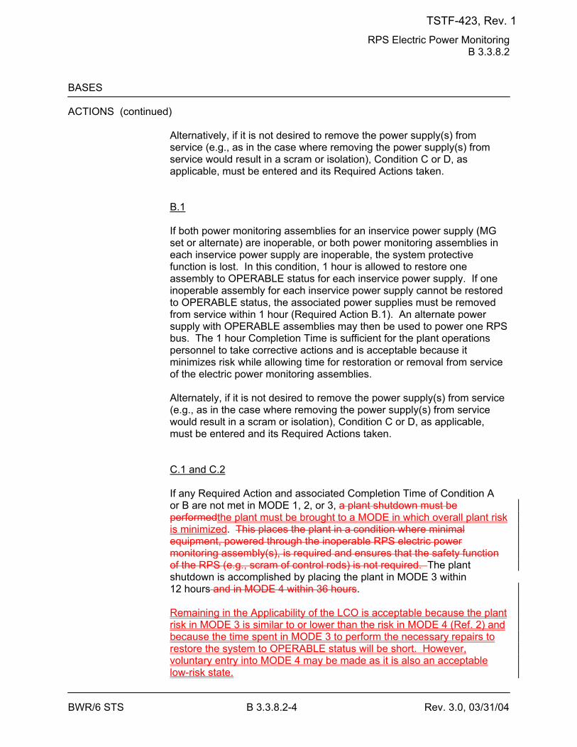
RPS Electric Power Monitoring B 3.3.8.2
BWR/6 STS B 3.3.8.2-4 Rev. 3.0, 03/31/04
BASES ACTIONS (continued)
Alternatively, if it is not desired to remove the power supply(s) from service (e.g., as in the case where removing the power supply(s) from service would result in a scram or isolation), Condition C or D, as applicable, must be entered and its Required Actions taken. B.1 If both power monitoring assemblies for an inservice power supply (MG set or alternate) are inoperable, or both power monitoring assemblies in each inservice power supply are inoperable, the system protective function is lost. In this condition, 1 hour is allowed to restore one assembly to OPERABLE status for each inservice power supply. If one inoperable assembly for each inservice power supply cannot be restored to OPERABLE status, the associated power supplies must be removed from service within 1 hour (Required Action B.1). An alternate power supply with OPERABLE assemblies may then be used to power one RPS bus. The 1 hour Completion Time is sufficient for the plant operations personnel to take corrective actions and is acceptable because it minimizes risk while allowing time for restoration or removal from service of the electric power monitoring assemblies. Alternately, if it is not desired to remove the power supply(s) from service (e.g., as in the case where removing the power supply(s) from service would result in a scram or isolation), Condition C or D, as applicable, must be entered and its Required Actions taken. C.1 and C.2 If any Required Action and associated Completion Time of Condition A or B are not met in MODE 1, 2, or 3, a plant shutdown must be performedthe plant must be brought to a MODE in which overall plant risk is minimized. This places the plant in a condition where minimal equipment, powered through the inoperable RPS electric power monitoring assembly(s), is required and ensures that the safety function of the RPS (e.g., scram of control rods) is not required. The plant shutdown is accomplished by placing the plant in MODE 3 within 12 hours and in MODE 4 within 36 hours. Remaining in the Applicability of the LCO is acceptable because the plant risk in MODE 3 is similar to or lower than the risk in MODE 4 (Ref. 2) and because the time spent in MODE 3 to perform the necessary repairs to restore the system to OPERABLE status will be short. However, voluntary entry into MODE 4 may be made as it is also an acceptable low-risk state.
TSTF-423, Rev. 1

RPS Electric Power Monitoring B 3.3.8.2
BWR/6 STS B 3.3.8.2-5 Rev. 3.0, 03/31/04
Required Action C.1 is modified by a Note that states that LCO 3.0.4.a is not applicable when entering MODE 3. This Note prohibits the use of LCO 3.0.4.a to enter MODE 3 during startup with the LCO not met. However, there is no restriction on the use of LCO 3.0.4.b, if applicable, because LCO 3.0.4.b requires performance of a risk assessment addressing inoperable systems and components, consideration of the results, determination of the acceptability of entering MODE 3, and establishment of risk management actions, if appropriate. LCO 3.0.4 is not applicable to, and the Note does not preclude, changes in MODES or other specified conditions in the Applicability that are required to comply with ACTIONS or that are part of a shutdown of the unit. The allowed Completion Times are is reasonable, based on operating experience, to reach the required plant conditions from full power conditions in an orderly manner and without challenging plant systems.
TSTF-423, Rev. 1
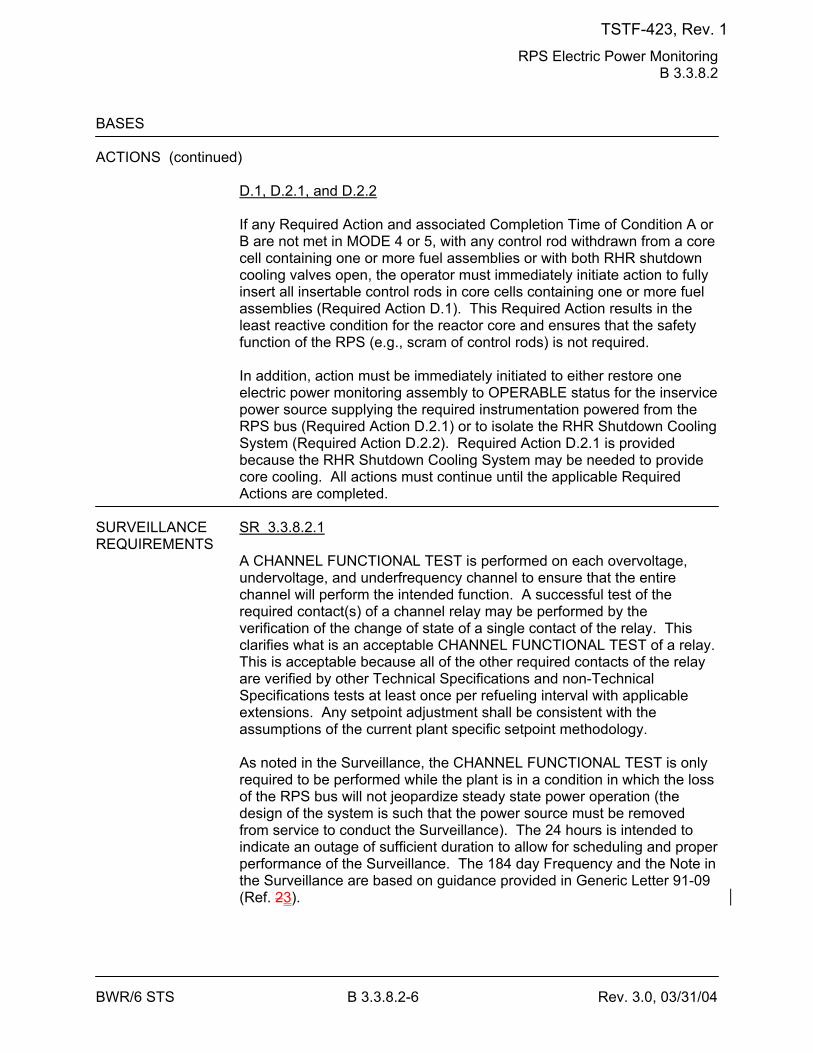
RPS Electric Power Monitoring B 3.3.8.2
BWR/6 STS B 3.3.8.2-6 Rev. 3.0, 03/31/04
BASES ACTIONS (continued)
D.1, D.2.1, and D.2.2 If any Required Action and associated Completion Time of Condition A or B are not met in MODE 4 or 5, with any control rod withdrawn from a core cell containing one or more fuel assemblies or with both RHR shutdown cooling valves open, the operator must immediately initiate action to fully insert all insertable control rods in core cells containing one or more fuel assemblies (Required Action D.1). This Required Action results in the least reactive condition for the reactor core and ensures that the safety function of the RPS (e.g., scram of control rods) is not required. In addition, action must be immediately initiated to either restore one electric power monitoring assembly to OPERABLE status for the inservice power source supplying the required instrumentation powered from the RPS bus (Required Action D.2.1) or to isolate the RHR Shutdown Cooling System (Required Action D.2.2). Required Action D.2.1 is provided because the RHR Shutdown Cooling System may be needed to provide core cooling. All actions must continue until the applicable Required Actions are completed.
SURVEILLANCE SR 3.3.8.2.1 REQUIREMENTS
A CHANNEL FUNCTIONAL TEST is performed on each overvoltage, undervoltage, and underfrequency channel to ensure that the entire channel will perform the intended function. A successful test of the required contact(s) of a channel relay may be performed by the verification of the change of state of a single contact of the relay. This clarifies what is an acceptable CHANNEL FUNCTIONAL TEST of a relay. This is acceptable because all of the other required contacts of the relay are verified by other Technical Specifications and non-Technical Specifications tests at least once per refueling interval with applicable extensions. Any setpoint adjustment shall be consistent with the assumptions of the current plant specific setpoint methodology. As noted in the Surveillance, the CHANNEL FUNCTIONAL TEST is only required to be performed while the plant is in a condition in which the loss of the RPS bus will not jeopardize steady state power operation (the design of the system is such that the power source must be removed from service to conduct the Surveillance). The 24 hours is intended to indicate an outage of sufficient duration to allow for scheduling and proper performance of the Surveillance. The 184 day Frequency and the Note in the Surveillance are based on guidance provided in Generic Letter 91-09 (Ref. 23).
TSTF-423, Rev. 1
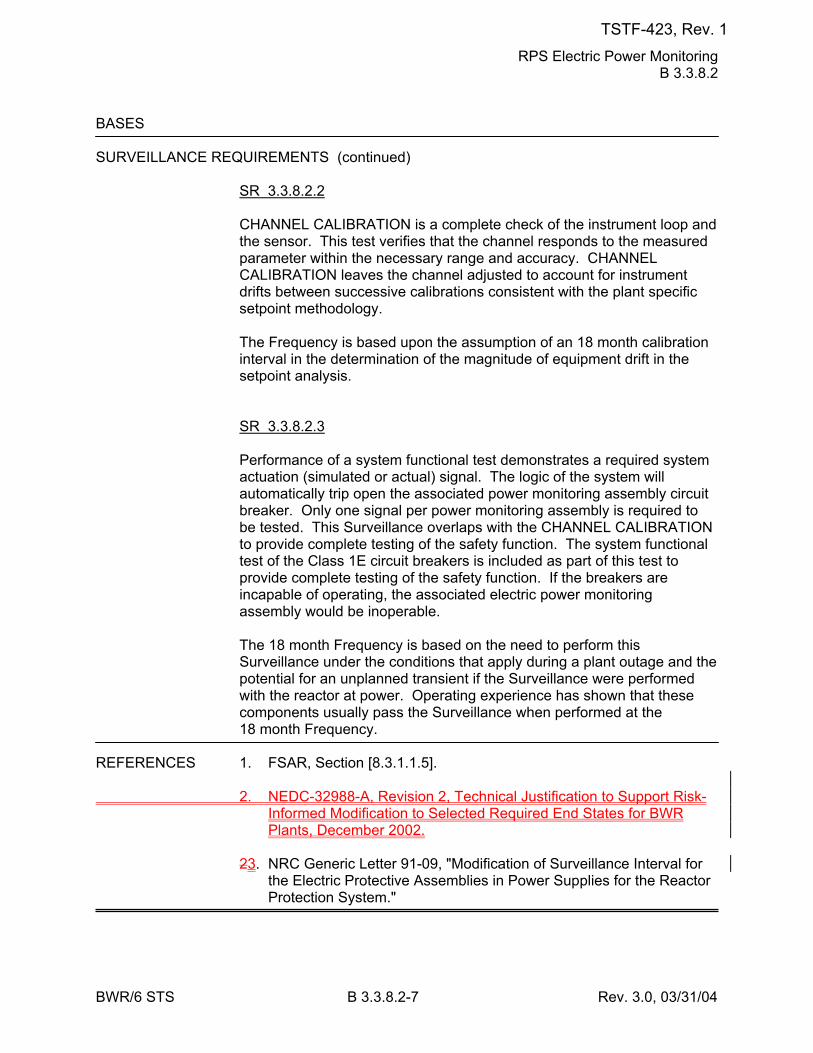
RPS Electric Power Monitoring B 3.3.8.2
BWR/6 STS B 3.3.8.2-7 Rev. 3.0, 03/31/04
BASES SURVEILLANCE REQUIREMENTS (continued)
SR 3.3.8.2.2 CHANNEL CALIBRATION is a complete check of the instrument loop and the sensor. This test verifies that the channel responds to the measured parameter within the necessary range and accuracy. CHANNEL CALIBRATION leaves the channel adjusted to account for instrument drifts between successive calibrations consistent with the plant specific setpoint methodology. The Frequency is based upon the assumption of an 18 month calibration interval in the determination of the magnitude of equipment drift in the setpoint analysis. SR 3.3.8.2.3 Performance of a system functional test demonstrates a required system actuation (simulated or actual) signal. The logic of the system will automatically trip open the associated power monitoring assembly circuit breaker. Only one signal per power monitoring assembly is required to be tested. This Surveillance overlaps with the CHANNEL CALIBRATION to provide complete testing of the safety function. The system functional test of the Class 1E circuit breakers is included as part of this test to provide complete testing of the safety function. If the breakers are incapable of operating, the associated electric power monitoring assembly would be inoperable. The 18 month Frequency is based on the need to perform this Surveillance under the conditions that apply during a plant outage and the potential for an unplanned transient if the Surveillance were performed with the reactor at power. Operating experience has shown that these components usually pass the Surveillance when performed at the 18 month Frequency.
REFERENCES 1. FSAR, Section [8.3.1.1.5]. 2. NEDC-32988-A, Revision 2, Technical Justification to Support Risk-
Informed Modification to Selected Required End States for BWR Plants, December 2002.
23. NRC Generic Letter 91-09, "Modification of Surveillance Interval for
the Electric Protective Assemblies in Power Supplies for the Reactor Protection System."
TSTF-423, Rev. 1
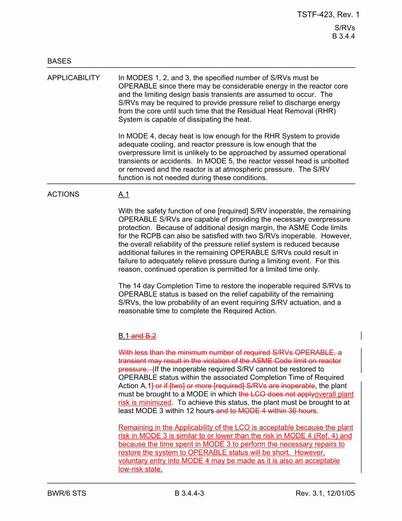
S/RVs B 3.4.4
BWR/6 STS B 3.4.4-3 Rev. 3.1, 12/01/05
BASES APPLICABILITY In MODES 1, 2, and 3, the specified number of S/RVs must be
OPERABLE since there may be considerable energy in the reactor core and the limiting design basis transients are assumed to occur. The S/RVs may be required to provide pressure relief to discharge energy from the core until such time that the Residual Heat Removal (RHR) System is capable of dissipating the heat.
In MODE 4, decay heat is low enough for the RHR System to provide adequate cooling, and reactor pressure is low enough that the overpressure limit is unlikely to be approached by assumed operational transients or accidents. In MODE 5, the reactor vessel head is unbolted or removed and the reactor is at atmospheric pressure. The S/RV function is not needed during these conditions.
ACTIONS A.1
With the safety function of one [required] S/RV inoperable, the remaining OPERABLE S/RVs are capable of providing the necessary overpressure protection. Because of additional design margin, the ASME Code limits for the RCPB can also be satisfied with two S/RVs inoperable. However, the overall reliability of the pressure relief system is reduced because additional failures in the remaining OPERABLE S/RVs could result in failure to adequately relieve pressure during a limiting event. For this reason, continued operation is permitted for a limited time only. The 14 day Completion Time to restore the inoperable required S/RVs to OPERABLE status is based on the relief capability of the remaining S/RVs, the low probability of an event requiring S/RV actuation, and a reasonable time to complete the Required Action. B.1 and B.2 With less than the minimum number of required S/RVs OPERABLE, a transient may result in the violation of the ASME Code limit on reactor pressure. [If the inoperable required S/RV cannot be restored to OPERABLE status within the associated Completion Time of Required Action A.1] or if [two] or more [required] S/RVs are inoperable, the plant must be brought to a MODE in which the LCO does not applyoverall plant risk is minimized. To achieve this status, the plant must be brought to at least MODE 3 within 12 hours and to MODE 4 within 36 hours. Remaining in the Applicability of the LCO is acceptable because the plant risk in MODE 3 is similar to or lower than the risk in MODE 4 (Ref. 4) and because the time spent in MODE 3 to perform the necessary repairs to restore the system to OPERABLE status will be short. However, voluntary entry into MODE 4 may be made as it is also an acceptable low-risk state.
TSTF-423, Rev. 1
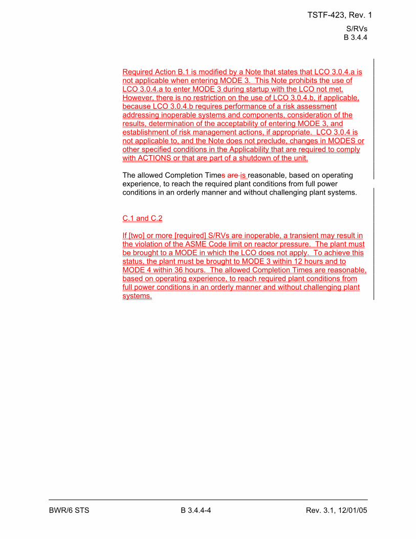
S/RVs B 3.4.4
BWR/6 STS B 3.4.4-4 Rev. 3.1, 12/01/05
Required Action B.1 is modified by a Note that states that LCO 3.0.4.a is not applicable when entering MODE 3. This Note prohibits the use of LCO 3.0.4.a to enter MODE 3 during startup with the LCO not met. However, there is no restriction on the use of LCO 3.0.4.b, if applicable, because LCO 3.0.4.b requires performance of a risk assessment addressing inoperable systems and components, consideration of the results, determination of the acceptability of entering MODE 3, and establishment of risk management actions, if appropriate. LCO 3.0.4 is not applicable to, and the Note does not preclude, changes in MODES or other specified conditions in the Applicability that are required to comply with ACTIONS or that are part of a shutdown of the unit. The allowed Completion Times are is reasonable, based on operating experience, to reach the required plant conditions from full power conditions in an orderly manner and without challenging plant systems. C.1 and C.2 If [two] or more [required] S/RVs are inoperable, a transient may result in the violation of the ASME Code limit on reactor pressure. The plant must be brought to a MODE in which the LCO does not apply. To achieve this status, the plant must be brought to MODE 3 within 12 hours and to MODE 4 within 36 hours. The allowed Completion Times are reasonable, based on operating experience, to reach required plant conditions from full power conditions in an orderly manner and without challenging plant systems.
TSTF-423, Rev. 1
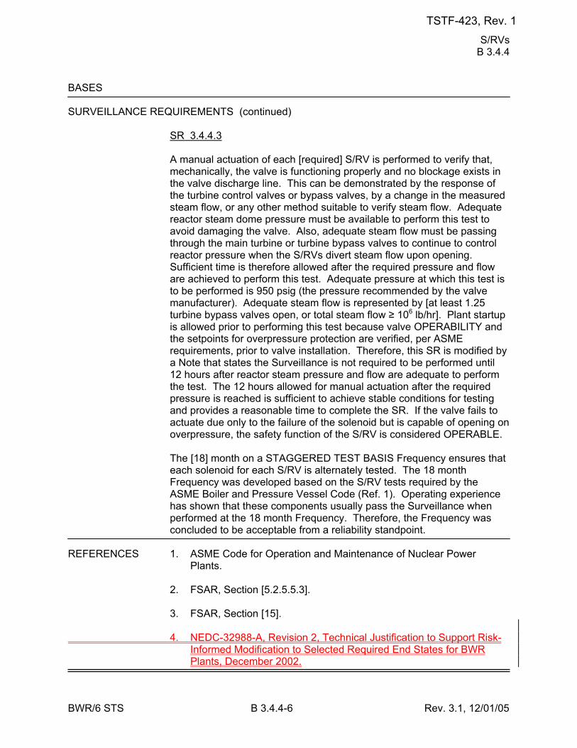
S/RVs B 3.4.4
BWR/6 STS B 3.4.4-6 Rev. 3.1, 12/01/05
BASES SURVEILLANCE REQUIREMENTS (continued)
SR 3.4.4.3 A manual actuation of each [required] S/RV is performed to verify that, mechanically, the valve is functioning properly and no blockage exists in the valve discharge line. This can be demonstrated by the response of the turbine control valves or bypass valves, by a change in the measured steam flow, or any other method suitable to verify steam flow. Adequate reactor steam dome pressure must be available to perform this test to avoid damaging the valve. Also, adequate steam flow must be passing through the main turbine or turbine bypass valves to continue to control reactor pressure when the S/RVs divert steam flow upon opening. Sufficient time is therefore allowed after the required pressure and flow are achieved to perform this test. Adequate pressure at which this test is to be performed is 950 psig (the pressure recommended by the valve manufacturer). Adequate steam flow is represented by [at least 1.25 turbine bypass valves open, or total steam flow ≥ 106 lb/hr]. Plant startup is allowed prior to performing this test because valve OPERABILITY and the setpoints for overpressure protection are verified, per ASME requirements, prior to valve installation. Therefore, this SR is modified by a Note that states the Surveillance is not required to be performed until 12 hours after reactor steam pressure and flow are adequate to perform the test. The 12 hours allowed for manual actuation after the required pressure is reached is sufficient to achieve stable conditions for testing and provides a reasonable time to complete the SR. If the valve fails to actuate due only to the failure of the solenoid but is capable of opening on overpressure, the safety function of the S/RV is considered OPERABLE. The [18] month on a STAGGERED TEST BASIS Frequency ensures that each solenoid for each S/RV is alternately tested. The 18 month Frequency was developed based on the S/RV tests required by the ASME Boiler and Pressure Vessel Code (Ref. 1). Operating experience has shown that these components usually pass the Surveillance when performed at the 18 month Frequency. Therefore, the Frequency was concluded to be acceptable from a reliability standpoint.
REFERENCES 1. ASME Code for Operation and Maintenance of Nuclear Power
Plants. 2. FSAR, Section [5.2.5.5.3]. 3. FSAR, Section [15]. 4. NEDC-32988-A, Revision 2, Technical Justification to Support Risk-
Informed Modification to Selected Required End States for BWR Plants, December 2002.
TSTF-423, Rev. 1
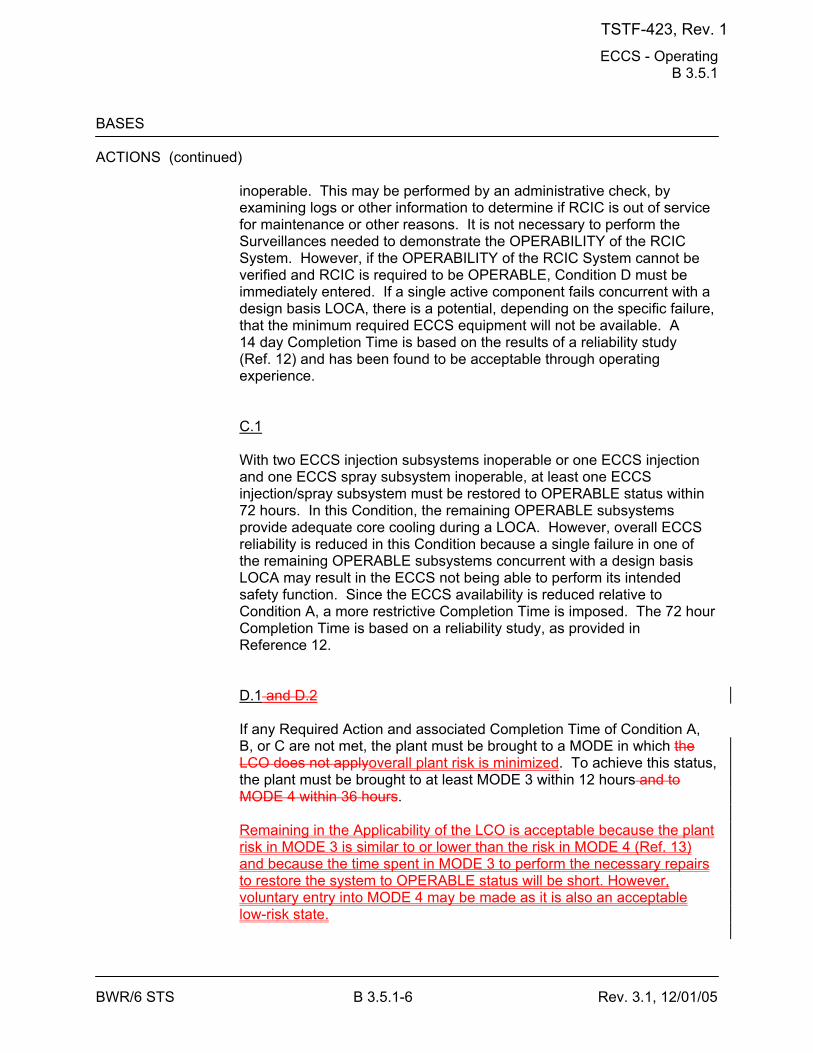
ECCS - Operating B 3.5.1
BWR/6 STS B 3.5.1-6 Rev. 3.1, 12/01/05
BASES ACTIONS (continued)
inoperable. This may be performed by an administrative check, by examining logs or other information to determine if RCIC is out of service for maintenance or other reasons. It is not necessary to perform the Surveillances needed to demonstrate the OPERABILITY of the RCIC System. However, if the OPERABILITY of the RCIC System cannot be verified and RCIC is required to be OPERABLE, Condition D must be immediately entered. If a single active component fails concurrent with a design basis LOCA, there is a potential, depending on the specific failure, that the minimum required ECCS equipment will not be available. A 14 day Completion Time is based on the results of a reliability study (Ref. 12) and has been found to be acceptable through operating experience. C.1 With two ECCS injection subsystems inoperable or one ECCS injection and one ECCS spray subsystem inoperable, at least one ECCS injection/spray subsystem must be restored to OPERABLE status within 72 hours. In this Condition, the remaining OPERABLE subsystems provide adequate core cooling during a LOCA. However, overall ECCS reliability is reduced in this Condition because a single failure in one of the remaining OPERABLE subsystems concurrent with a design basis LOCA may result in the ECCS not being able to perform its intended safety function. Since the ECCS availability is reduced relative to Condition A, a more restrictive Completion Time is imposed. The 72 hour Completion Time is based on a reliability study, as provided in Reference 12. D.1 and D.2 If any Required Action and associated Completion Time of Condition A, B, or C are not met, the plant must be brought to a MODE in which the LCO does not applyoverall plant risk is minimized. To achieve this status, the plant must be brought to at least MODE 3 within 12 hours and to MODE 4 within 36 hours. Remaining in the Applicability of the LCO is acceptable because the plant risk in MODE 3 is similar to or lower than the risk in MODE 4 (Ref. 13) and because the time spent in MODE 3 to perform the necessary repairs to restore the system to OPERABLE status will be short. However, voluntary entry into MODE 4 may be made as it is also an acceptable low-risk state.
TSTF-423, Rev. 1

ECCS - Operating B 3.5.1
BWR/6 STS B 3.5.1-7 Rev. 3.1, 12/01/05
Required Action D.1 is modified by a Note that states that LCO 3.0.4.a is not applicable when entering MODE 3. This Note prohibits the use of LCO 3.0.4.a to enter MODE 3 during startup with the LCO not met. However, there is no restriction on the use of LCO 3.0.4.b, if applicable, because LCO 3.0.4.b requires performance of a risk assessment addressing inoperable systems and components, consideration of the results, determination of the acceptability of entering MODE 3, and establishment of risk management actions, if appropriate. LCO 3.0.4 is not applicable to, and the Note does not preclude, changes in MODES or other specified conditions in the Applicability that are required to comply with ACTIONS or that are part of a shutdown of the unit. The allowed Completion Times are is reasonable, based on operating experience, to reach the required plant conditions from full power conditions in an orderly manner and without challenging plant systems.
TSTF-423, Rev. 1
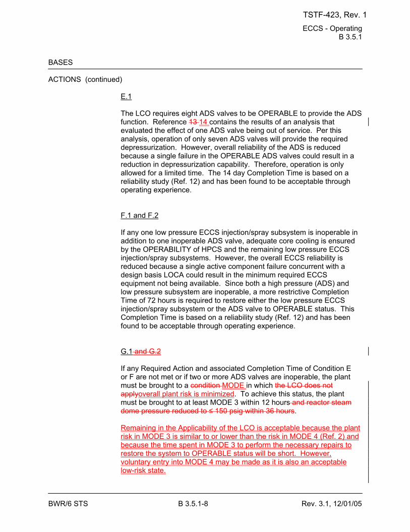
ECCS - Operating B 3.5.1
BWR/6 STS B 3.5.1-8 Rev. 3.1, 12/01/05
BASES ACTIONS (continued)
E.1 The LCO requires eight ADS valves to be OPERABLE to provide the ADS function. Reference 13 14 contains the results of an analysis that evaluated the effect of one ADS valve being out of service. Per this analysis, operation of only seven ADS valves will provide the required depressurization. However, overall reliability of the ADS is reduced because a single failure in the OPERABLE ADS valves could result in a reduction in depressurization capability. Therefore, operation is only allowed for a limited time. The 14 day Completion Time is based on a reliability study (Ref. 12) and has been found to be acceptable through operating experience. F.1 and F.2 If any one low pressure ECCS injection/spray subsystem is inoperable in addition to one inoperable ADS valve, adequate core cooling is ensured by the OPERABILITY of HPCS and the remaining low pressure ECCS injection/spray subsystems. However, the overall ECCS reliability is reduced because a single active component failure concurrent with a design basis LOCA could result in the minimum required ECCS equipment not being available. Since both a high pressure (ADS) and low pressure subsystem are inoperable, a more restrictive Completion Time of 72 hours is required to restore either the low pressure ECCS injection/spray subsystem or the ADS valve to OPERABLE status. This Completion Time is based on a reliability study (Ref. 12) and has been found to be acceptable through operating experience. G.1 and G.2 If any Required Action and associated Completion Time of Condition E or F are not met or if two or more ADS valves are inoperable, the plant must be brought to a condition MODE in which the LCO does not applyoverall plant risk is minimized. To achieve this status, the plant must be brought to at least MODE 3 within 12 hours and reactor steam dome pressure reduced to ≤ 150 psig within 36 hours. Remaining in the Applicability of the LCO is acceptable because the plant risk in MODE 3 is similar to or lower than the risk in MODE 4 (Ref. 2) and because the time spent in MODE 3 to perform the necessary repairs to restore the system to OPERABLE status will be short. However, voluntary entry into MODE 4 may be made as it is also an acceptable low-risk state.
TSTF-423, Rev. 1

ECCS - Operating B 3.5.1
BWR/6 STS B 3.5.1-9 Rev. 3.1, 12/01/05
Required Action G.1 is modified by a Note that states that LCO 3.0.4.a is not applicable when entering MODE 3. This Note prohibits the use of LCO 3.0.4.a to enter MODE 3 during startup with the LCO not met. However, there is no restriction on the use of LCO 3.0.4.b, if applicable, because LCO 3.0.4.b requires performance of a risk assessment addressing inoperable systems and components, consideration of the results, determination of the acceptability of entering MODE 3, and establishment of risk management actions, if appropriate. LCO 3.0.4 is not applicable to, and the Note does not preclude, changes in MODES or other specified conditions in the Applicability that are required to comply with ACTIONS or that are part of a shutdown of the unit. The allowed Completion Times are is reasonable, based on operating experience, to reach the required plant conditions from full power conditions in an orderly manner and without challenging plant systems.
TSTF-423, Rev. 1
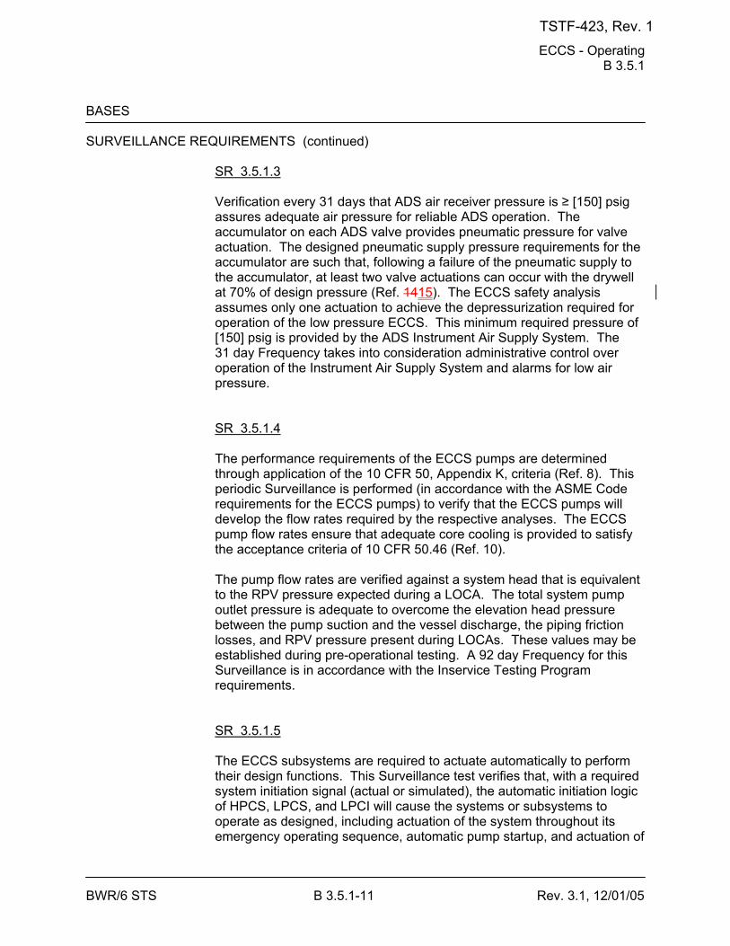
ECCS - Operating B 3.5.1
BWR/6 STS B 3.5.1-11 Rev. 3.1, 12/01/05
BASES SURVEILLANCE REQUIREMENTS (continued)
SR 3.5.1.3 Verification every 31 days that ADS air receiver pressure is ≥ [150] psig assures adequate air pressure for reliable ADS operation. The accumulator on each ADS valve provides pneumatic pressure for valve actuation. The designed pneumatic supply pressure requirements for the accumulator are such that, following a failure of the pneumatic supply to the accumulator, at least two valve actuations can occur with the drywell at 70% of design pressure (Ref. 1415). The ECCS safety analysis assumes only one actuation to achieve the depressurization required for operation of the low pressure ECCS. This minimum required pressure of [150] psig is provided by the ADS Instrument Air Supply System. The 31 day Frequency takes into consideration administrative control over operation of the Instrument Air Supply System and alarms for low air pressure. SR 3.5.1.4 The performance requirements of the ECCS pumps are determined through application of the 10 CFR 50, Appendix K, criteria (Ref. 8). This periodic Surveillance is performed (in accordance with the ASME Code requirements for the ECCS pumps) to verify that the ECCS pumps will develop the flow rates required by the respective analyses. The ECCS pump flow rates ensure that adequate core cooling is provided to satisfy the acceptance criteria of 10 CFR 50.46 (Ref. 10). The pump flow rates are verified against a system head that is equivalent to the RPV pressure expected during a LOCA. The total system pump outlet pressure is adequate to overcome the elevation head pressure between the pump suction and the vessel discharge, the piping friction losses, and RPV pressure present during LOCAs. These values may be established during pre-operational testing. A 92 day Frequency for this Surveillance is in accordance with the Inservice Testing Program requirements. SR 3.5.1.5 The ECCS subsystems are required to actuate automatically to perform their design functions. This Surveillance test verifies that, with a required system initiation signal (actual or simulated), the automatic initiation logic of HPCS, LPCS, and LPCI will cause the systems or subsystems to operate as designed, including actuation of the system throughout its emergency operating sequence, automatic pump startup, and actuation of
TSTF-423, Rev. 1
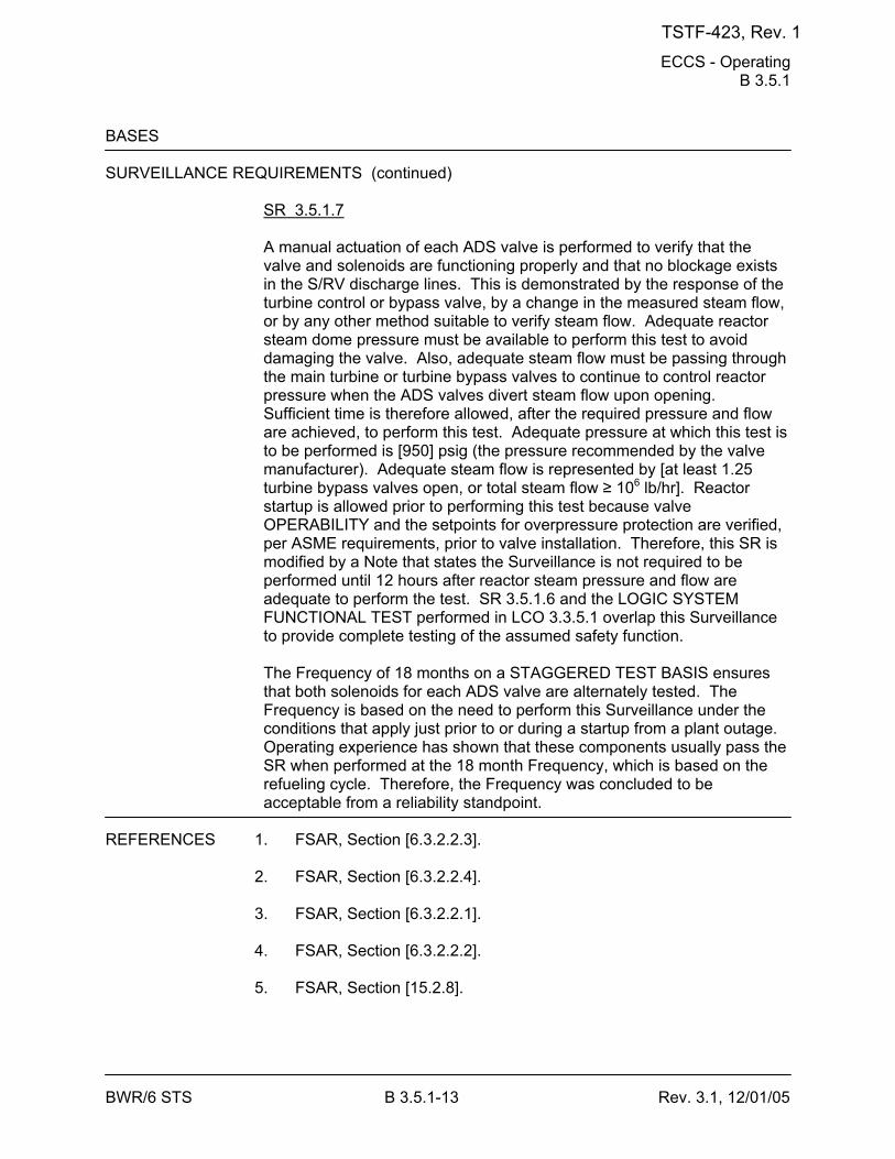
ECCS - Operating B 3.5.1
BWR/6 STS B 3.5.1-13 Rev. 3.1, 12/01/05
BASES SURVEILLANCE REQUIREMENTS (continued)
SR 3.5.1.7 A manual actuation of each ADS valve is performed to verify that the valve and solenoids are functioning properly and that no blockage exists in the S/RV discharge lines. This is demonstrated by the response of the turbine control or bypass valve, by a change in the measured steam flow, or by any other method suitable to verify steam flow. Adequate reactor steam dome pressure must be available to perform this test to avoid damaging the valve. Also, adequate steam flow must be passing through the main turbine or turbine bypass valves to continue to control reactor pressure when the ADS valves divert steam flow upon opening. Sufficient time is therefore allowed, after the required pressure and flow are achieved, to perform this test. Adequate pressure at which this test is to be performed is [950] psig (the pressure recommended by the valve manufacturer). Adequate steam flow is represented by [at least 1.25 turbine bypass valves open, or total steam flow ≥ 106 lb/hr]. Reactor startup is allowed prior to performing this test because valve OPERABILITY and the setpoints for overpressure protection are verified, per ASME requirements, prior to valve installation. Therefore, this SR is modified by a Note that states the Surveillance is not required to be performed until 12 hours after reactor steam pressure and flow are adequate to perform the test. SR 3.5.1.6 and the LOGIC SYSTEM FUNCTIONAL TEST performed in LCO 3.3.5.1 overlap this Surveillance to provide complete testing of the assumed safety function. The Frequency of 18 months on a STAGGERED TEST BASIS ensures that both solenoids for each ADS valve are alternately tested. The Frequency is based on the need to perform this Surveillance under the conditions that apply just prior to or during a startup from a plant outage. Operating experience has shown that these components usually pass the SR when performed at the 18 month Frequency, which is based on the refueling cycle. Therefore, the Frequency was concluded to be acceptable from a reliability standpoint.
REFERENCES 1. FSAR, Section [6.3.2.2.3]. 2. FSAR, Section [6.3.2.2.4]. 3. FSAR, Section [6.3.2.2.1]. 4. FSAR, Section [6.3.2.2.2]. 5. FSAR, Section [15.2.8].
TSTF-423, Rev. 1
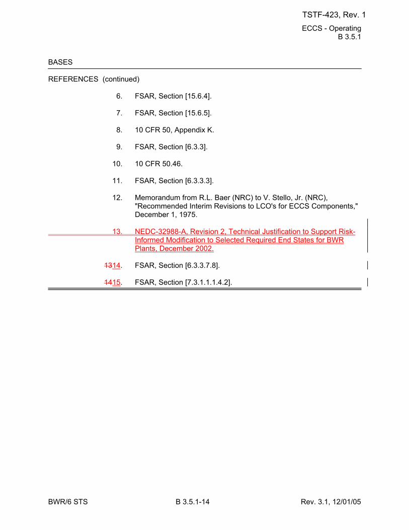
ECCS - Operating B 3.5.1
BWR/6 STS B 3.5.1-14 Rev. 3.1, 12/01/05
BASES REFERENCES (continued) 6. FSAR, Section [15.6.4]. 7. FSAR, Section [15.6.5]. 8. 10 CFR 50, Appendix K. 9. FSAR, Section [6.3.3]. 10. 10 CFR 50.46. 11. FSAR, Section [6.3.3.3]. 12. Memorandum from R.L. Baer (NRC) to V. Stello, Jr. (NRC),
"Recommended Interim Revisions to LCO's for ECCS Components," December 1, 1975.
13. NEDC-32988-A, Revision 2, Technical Justification to Support Risk-
Informed Modification to Selected Required End States for BWR Plants, December 2002.
1314. FSAR, Section [6.3.3.7.8]. 1415. FSAR, Section [7.3.1.1.1.4.2].
TSTF-423, Rev. 1
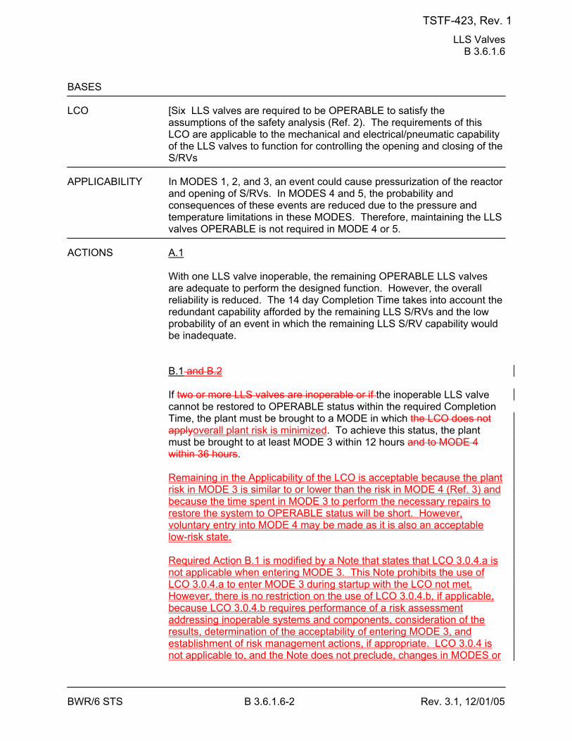
LLS Valves B 3.6.1.6
BWR/6 STS B 3.6.1.6-2 Rev. 3.1, 12/01/05
BASES LCO [Six LLS valves are required to be OPERABLE to satisfy the
assumptions of the safety analysis (Ref. 2). The requirements of this LCO are applicable to the mechanical and electrical/pneumatic capability of the LLS valves to function for controlling the opening and closing of the S/RVs
APPLICABILITY In MODES 1, 2, and 3, an event could cause pressurization of the reactor
and opening of S/RVs. In MODES 4 and 5, the probability and consequences of these events are reduced due to the pressure and temperature limitations in these MODES. Therefore, maintaining the LLS valves OPERABLE is not required in MODE 4 or 5.
ACTIONS A.1
With one LLS valve inoperable, the remaining OPERABLE LLS valves are adequate to perform the designed function. However, the overall reliability is reduced. The 14 day Completion Time takes into account the redundant capability afforded by the remaining LLS S/RVs and the low probability of an event in which the remaining LLS S/RV capability would be inadequate. B.1 and B.2 If two or more LLS valves are inoperable or if the inoperable LLS valve cannot be restored to OPERABLE status within the required Completion Time, the plant must be brought to a MODE in which the LCO does not applyoverall plant risk is minimized. To achieve this status, the plant must be brought to at least MODE 3 within 12 hours and to MODE 4 within 36 hours. Remaining in the Applicability of the LCO is acceptable because the plant risk in MODE 3 is similar to or lower than the risk in MODE 4 (Ref. 3) and because the time spent in MODE 3 to perform the necessary repairs to restore the system to OPERABLE status will be short. However, voluntary entry into MODE 4 may be made as it is also an acceptable low-risk state. Required Action B.1 is modified by a Note that states that LCO 3.0.4.a is not applicable when entering MODE 3. This Note prohibits the use of LCO 3.0.4.a to enter MODE 3 during startup with the LCO not met. However, there is no restriction on the use of LCO 3.0.4.b, if applicable, because LCO 3.0.4.b requires performance of a risk assessment addressing inoperable systems and components, consideration of the results, determination of the acceptability of entering MODE 3, and establishment of risk management actions, if appropriate. LCO 3.0.4 is not applicable to, and the Note does not preclude, changes in MODES or
TSTF-423, Rev. 1
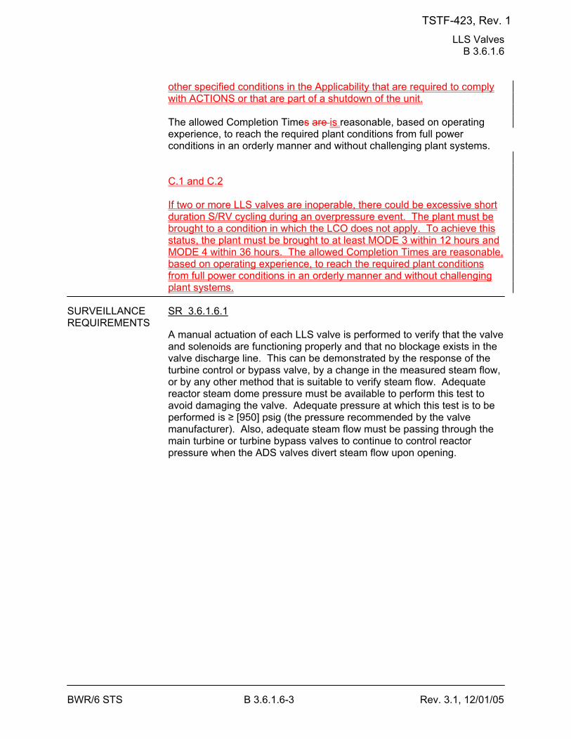
LLS Valves B 3.6.1.6
BWR/6 STS B 3.6.1.6-3 Rev. 3.1, 12/01/05
other specified conditions in the Applicability that are required to comply with ACTIONS or that are part of a shutdown of the unit. The allowed Completion Times are is reasonable, based on operating experience, to reach the required plant conditions from full power conditions in an orderly manner and without challenging plant systems. C.1 and C.2 If two or more LLS valves are inoperable, there could be excessive short duration S/RV cycling during an overpressure event. The plant must be brought to a condition in which the LCO does not apply. To achieve this status, the plant must be brought to at least MODE 3 within 12 hours and MODE 4 within 36 hours. The allowed Completion Times are reasonable, based on operating experience, to reach the required plant conditions from full power conditions in an orderly manner and without challenging plant systems.
SURVEILLANCE SR 3.6.1.6.1 REQUIREMENTS
A manual actuation of each LLS valve is performed to verify that the valve and solenoids are functioning properly and that no blockage exists in the valve discharge line. This can be demonstrated by the response of the turbine control or bypass valve, by a change in the measured steam flow, or by any other method that is suitable to verify steam flow. Adequate reactor steam dome pressure must be available to perform this test to avoid damaging the valve. Adequate pressure at which this test is to be performed is ≥ [950] psig (the pressure recommended by the valve manufacturer). Also, adequate steam flow must be passing through the main turbine or turbine bypass valves to continue to control reactor pressure when the ADS valves divert steam flow upon opening.
TSTF-423, Rev. 1
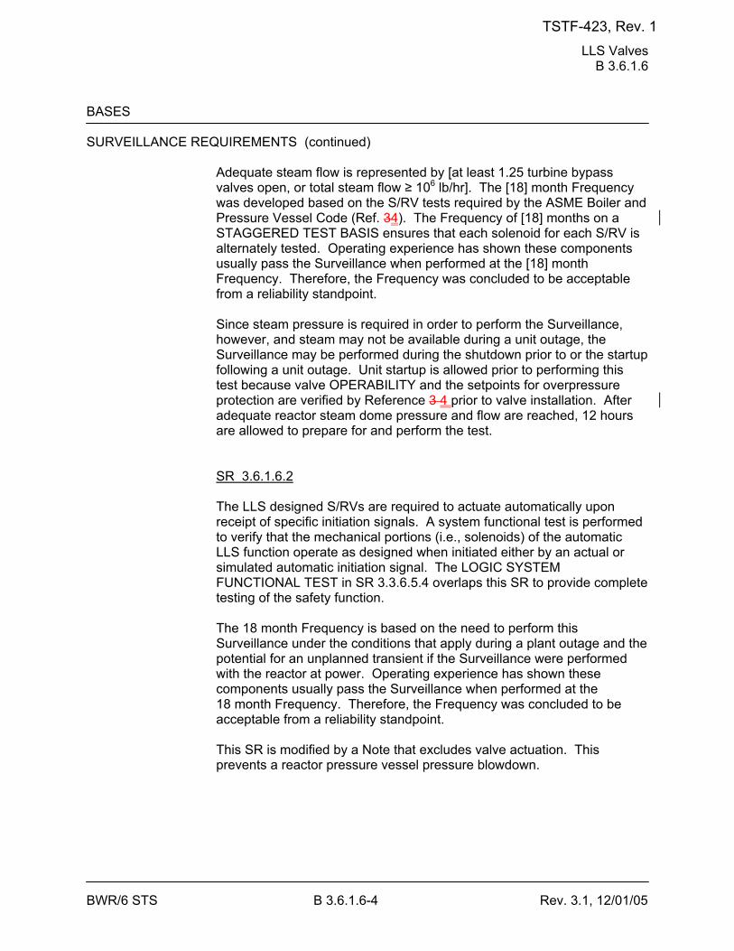
LLS Valves B 3.6.1.6
BWR/6 STS B 3.6.1.6-4 Rev. 3.1, 12/01/05
BASES SURVEILLANCE REQUIREMENTS (continued)
Adequate steam flow is represented by [at least 1.25 turbine bypass valves open, or total steam flow ≥ 106 lb/hr]. The [18] month Frequency was developed based on the S/RV tests required by the ASME Boiler and Pressure Vessel Code (Ref. 34). The Frequency of [18] months on a STAGGERED TEST BASIS ensures that each solenoid for each S/RV is alternately tested. Operating experience has shown these components usually pass the Surveillance when performed at the [18] month Frequency. Therefore, the Frequency was concluded to be acceptable from a reliability standpoint. Since steam pressure is required in order to perform the Surveillance, however, and steam may not be available during a unit outage, the Surveillance may be performed during the shutdown prior to or the startup following a unit outage. Unit startup is allowed prior to performing this test because valve OPERABILITY and the setpoints for overpressure protection are verified by Reference 3 4 prior to valve installation. After adequate reactor steam dome pressure and flow are reached, 12 hours are allowed to prepare for and perform the test. SR 3.6.1.6.2 The LLS designed S/RVs are required to actuate automatically upon receipt of specific initiation signals. A system functional test is performed to verify that the mechanical portions (i.e., solenoids) of the automatic LLS function operate as designed when initiated either by an actual or simulated automatic initiation signal. The LOGIC SYSTEM FUNCTIONAL TEST in SR 3.3.6.5.4 overlaps this SR to provide complete testing of the safety function. The 18 month Frequency is based on the need to perform this Surveillance under the conditions that apply during a plant outage and the potential for an unplanned transient if the Surveillance were performed with the reactor at power. Operating experience has shown these components usually pass the Surveillance when performed at the 18 month Frequency. Therefore, the Frequency was concluded to be acceptable from a reliability standpoint. This SR is modified by a Note that excludes valve actuation. This prevents a reactor pressure vessel pressure blowdown.
TSTF-423, Rev. 1
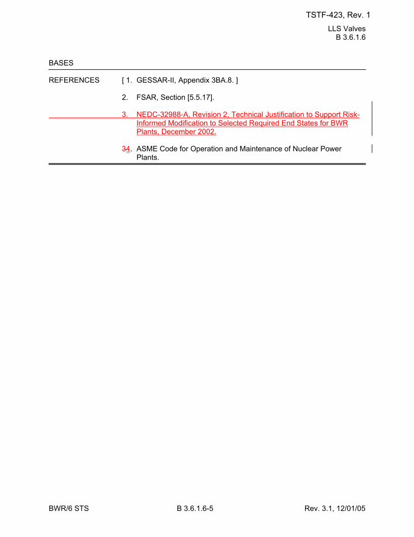
LLS Valves B 3.6.1.6
BWR/6 STS B 3.6.1.6-5 Rev. 3.1, 12/01/05
BASES REFERENCES [ 1. GESSAR-II, Appendix 3BA.8. ] 2. FSAR, Section [5.5.17]. 3. NEDC-32988-A, Revision 2, Technical Justification to Support Risk-
Informed Modification to Selected Required End States for BWR Plants, December 2002.
34. ASME Code for Operation and Maintenance of Nuclear Power
Plants.
TSTF-423, Rev. 1
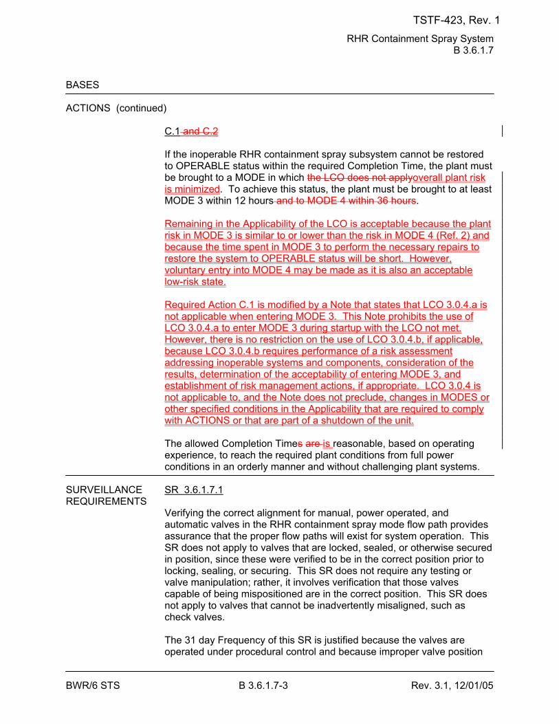
RHR Containment Spray System B 3.6.1.7
BWR/6 STS B 3.6.1.7-3 Rev. 3.1, 12/01/05
BASES ACTIONS (continued)
C.1 and C.2 If the inoperable RHR containment spray subsystem cannot be restored to OPERABLE status within the required Completion Time, the plant must be brought to a MODE in which the LCO does not applyoverall plant risk is minimized. To achieve this status, the plant must be brought to at least MODE 3 within 12 hours and to MODE 4 within 36 hours. Remaining in the Applicability of the LCO is acceptable because the plant risk in MODE 3 is similar to or lower than the risk in MODE 4 (Ref. 2) and because the time spent in MODE 3 to perform the necessary repairs to restore the system to OPERABLE status will be short. However, voluntary entry into MODE 4 may be made as it is also an acceptable low-risk state. Required Action C.1 is modified by a Note that states that LCO 3.0.4.a is not applicable when entering MODE 3. This Note prohibits the use of LCO 3.0.4.a to enter MODE 3 during startup with the LCO not met. However, there is no restriction on the use of LCO 3.0.4.b, if applicable, because LCO 3.0.4.b requires performance of a risk assessment addressing inoperable systems and components, consideration of the results, determination of the acceptability of entering MODE 3, and establishment of risk management actions, if appropriate. LCO 3.0.4 is not applicable to, and the Note does not preclude, changes in MODES or other specified conditions in the Applicability that are required to comply with ACTIONS or that are part of a shutdown of the unit. The allowed Completion Times are is reasonable, based on operating experience, to reach the required plant conditions from full power conditions in an orderly manner and without challenging plant systems.
SURVEILLANCE SR 3.6.1.7.1 REQUIREMENTS
Verifying the correct alignment for manual, power operated, and automatic valves in the RHR containment spray mode flow path provides assurance that the proper flow paths will exist for system operation. This SR does not apply to valves that are locked, sealed, or otherwise secured in position, since these were verified to be in the correct position prior to locking, sealing, or securing. This SR does not require any testing or valve manipulation; rather, it involves verification that those valves capable of being mispositioned are in the correct position. This SR does not apply to valves that cannot be inadvertently misaligned, such as check valves. The 31 day Frequency of this SR is justified because the valves are operated under procedural control and because improper valve position
TSTF-423, Rev. 1
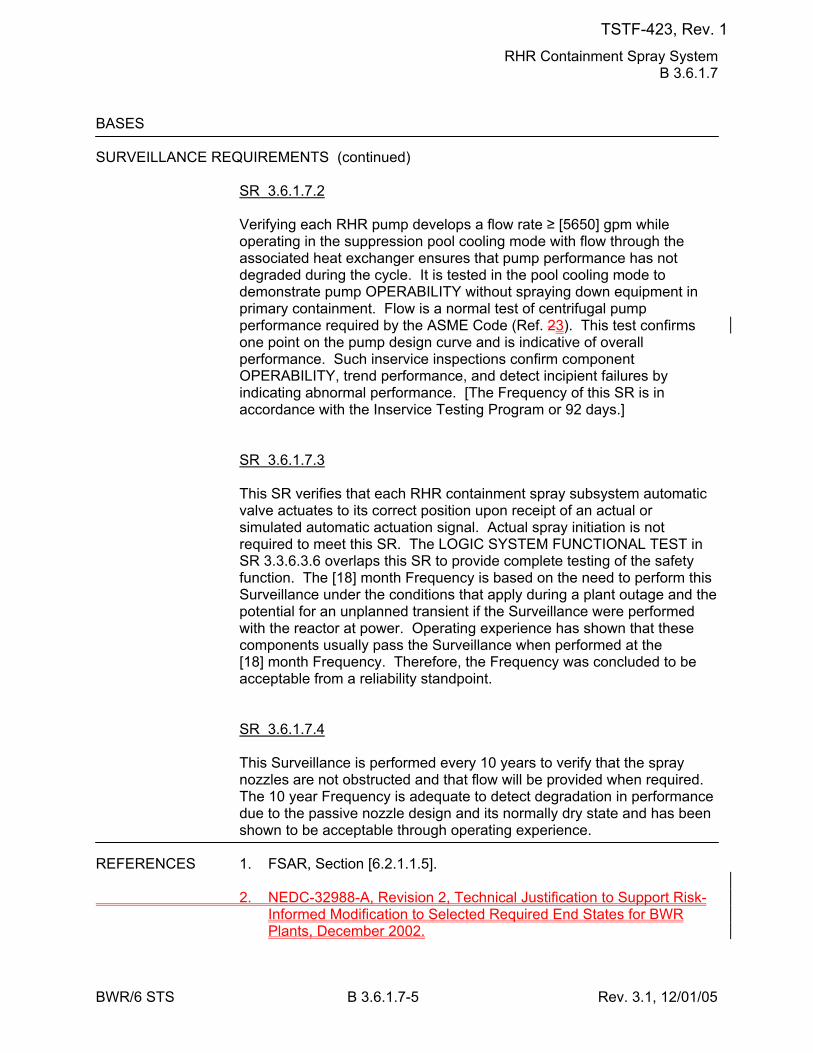
RHR Containment Spray System B 3.6.1.7
BWR/6 STS B 3.6.1.7-5 Rev. 3.1, 12/01/05
BASES SURVEILLANCE REQUIREMENTS (continued)
SR 3.6.1.7.2 Verifying each RHR pump develops a flow rate ≥ [5650] gpm while operating in the suppression pool cooling mode with flow through the associated heat exchanger ensures that pump performance has not degraded during the cycle. It is tested in the pool cooling mode to demonstrate pump OPERABILITY without spraying down equipment in primary containment. Flow is a normal test of centrifugal pump performance required by the ASME Code (Ref. 23). This test confirms one point on the pump design curve and is indicative of overall performance. Such inservice inspections confirm component OPERABILITY, trend performance, and detect incipient failures by indicating abnormal performance. [The Frequency of this SR is in accordance with the Inservice Testing Program or 92 days.] SR 3.6.1.7.3 This SR verifies that each RHR containment spray subsystem automatic valve actuates to its correct position upon receipt of an actual or simulated automatic actuation signal. Actual spray initiation is not required to meet this SR. The LOGIC SYSTEM FUNCTIONAL TEST in SR 3.3.6.3.6 overlaps this SR to provide complete testing of the safety function. The [18] month Frequency is based on the need to perform this Surveillance under the conditions that apply during a plant outage and the potential for an unplanned transient if the Surveillance were performed with the reactor at power. Operating experience has shown that these components usually pass the Surveillance when performed at the [18] month Frequency. Therefore, the Frequency was concluded to be acceptable from a reliability standpoint. SR 3.6.1.7.4 This Surveillance is performed every 10 years to verify that the spray nozzles are not obstructed and that flow will be provided when required. The 10 year Frequency is adequate to detect degradation in performance due to the passive nozzle design and its normally dry state and has been shown to be acceptable through operating experience.
REFERENCES 1. FSAR, Section [6.2.1.1.5]. 2. NEDC-32988-A, Revision 2, Technical Justification to Support Risk-
Informed Modification to Selected Required End States for BWR Plants, December 2002.
TSTF-423, Rev. 1
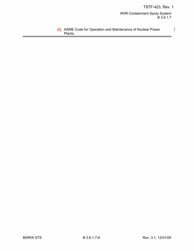
RHR Containment Spray System B 3.6.1.7
BWR/6 STS B 3.6.1.7-6 Rev. 3.1, 12/01/05
23. ASME Code for Operation and Maintenance of Nuclear Power Plants.
TSTF-423, Rev. 1
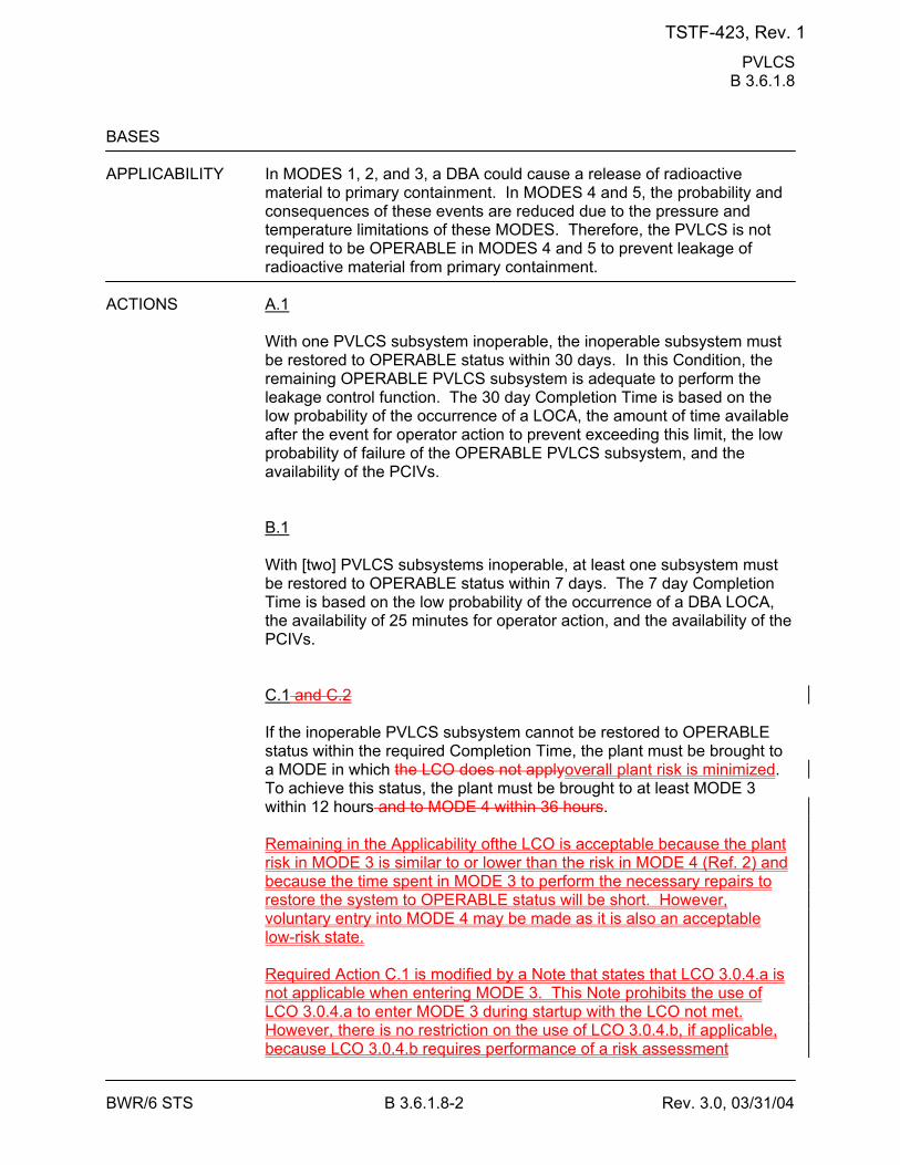
PVLCS B 3.6.1.8
BWR/6 STS B 3.6.1.8-2 Rev. 3.0, 03/31/04
BASES APPLICABILITY In MODES 1, 2, and 3, a DBA could cause a release of radioactive
material to primary containment. In MODES 4 and 5, the probability and consequences of these events are reduced due to the pressure and temperature limitations of these MODES. Therefore, the PVLCS is not required to be OPERABLE in MODES 4 and 5 to prevent leakage of radioactive material from primary containment.
ACTIONS A.1
With one PVLCS subsystem inoperable, the inoperable subsystem must be restored to OPERABLE status within 30 days. In this Condition, the remaining OPERABLE PVLCS subsystem is adequate to perform the leakage control function. The 30 day Completion Time is based on the low probability of the occurrence of a LOCA, the amount of time available after the event for operator action to prevent exceeding this limit, the low probability of failure of the OPERABLE PVLCS subsystem, and the availability of the PCIVs. B.1 With [two] PVLCS subsystems inoperable, at least one subsystem must be restored to OPERABLE status within 7 days. The 7 day Completion Time is based on the low probability of the occurrence of a DBA LOCA, the availability of 25 minutes for operator action, and the availability of the PCIVs. C.1 and C.2 If the inoperable PVLCS subsystem cannot be restored to OPERABLE status within the required Completion Time, the plant must be brought to a MODE in which the LCO does not applyoverall plant risk is minimized. To achieve this status, the plant must be brought to at least MODE 3 within 12 hours and to MODE 4 within 36 hours. Remaining in the Applicability ofthe LCO is acceptable because the plant risk in MODE 3 is similar to or lower than the risk in MODE 4 (Ref. 2) and because the time spent in MODE 3 to perform the necessary repairs to restore the system to OPERABLE status will be short. However, voluntary entry into MODE 4 may be made as it is also an acceptable low-risk state. Required Action C.1 is modified by a Note that states that LCO 3.0.4.a is not applicable when entering MODE 3. This Note prohibits the use of LCO 3.0.4.a to enter MODE 3 during startup with the LCO not met. However, there is no restriction on the use of LCO 3.0.4.b, if applicable, because LCO 3.0.4.b requires performance of a risk assessment
TSTF-423, Rev. 1
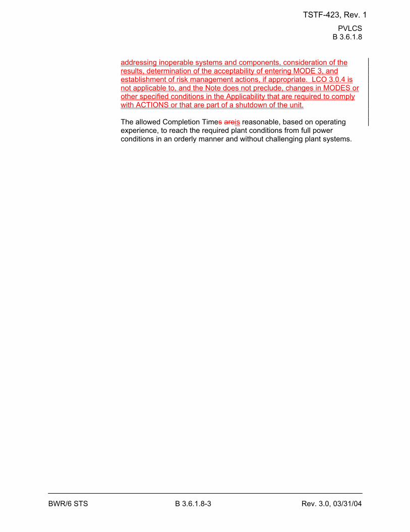
PVLCS B 3.6.1.8
BWR/6 STS B 3.6.1.8-3 Rev. 3.0, 03/31/04
addressing inoperable systems and components, consideration of the results, determination of the acceptability of entering MODE 3, and establishment of risk management actions, if appropriate. LCO 3.0.4 is not applicable to, and the Note does not preclude, changes in MODES or other specified conditions in the Applicability that are required to comply with ACTIONS or that are part of a shutdown of the unit. The allowed Completion Times areis reasonable, based on operating experience, to reach the required plant conditions from full power conditions in an orderly manner and without challenging plant systems.
TSTF-423, Rev. 1
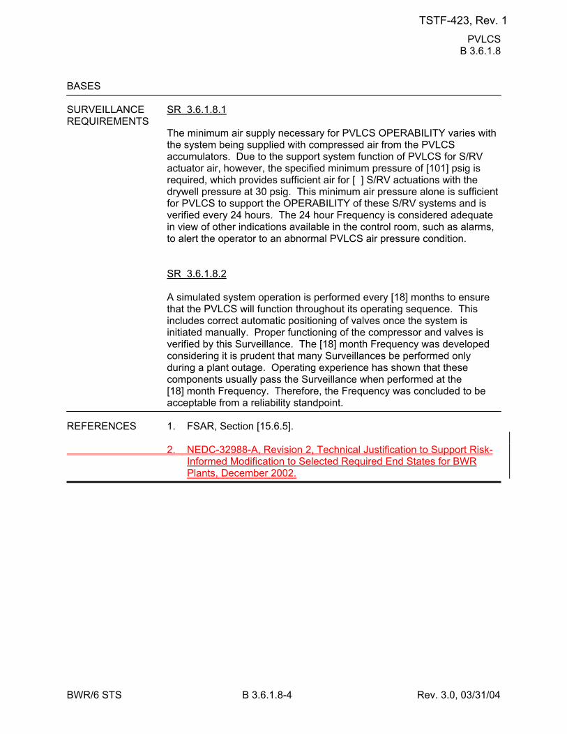
PVLCS B 3.6.1.8
BWR/6 STS B 3.6.1.8-4 Rev. 3.0, 03/31/04
BASES SURVEILLANCE SR 3.6.1.8.1 REQUIREMENTS
The minimum air supply necessary for PVLCS OPERABILITY varies with the system being supplied with compressed air from the PVLCS accumulators. Due to the support system function of PVLCS for S/RV actuator air, however, the specified minimum pressure of [101] psig is required, which provides sufficient air for [ ] S/RV actuations with the drywell pressure at 30 psig. This minimum air pressure alone is sufficient for PVLCS to support the OPERABILITY of these S/RV systems and is verified every 24 hours. The 24 hour Frequency is considered adequate in view of other indications available in the control room, such as alarms, to alert the operator to an abnormal PVLCS air pressure condition. SR 3.6.1.8.2 A simulated system operation is performed every [18] months to ensure that the PVLCS will function throughout its operating sequence. This includes correct automatic positioning of valves once the system is initiated manually. Proper functioning of the compressor and valves is verified by this Surveillance. The [18] month Frequency was developed considering it is prudent that many Surveillances be performed only during a plant outage. Operating experience has shown that these components usually pass the Surveillance when performed at the [18] month Frequency. Therefore, the Frequency was concluded to be acceptable from a reliability standpoint.
REFERENCES 1. FSAR, Section [15.6.5]. 2. NEDC-32988-A, Revision 2, Technical Justification to Support Risk-
Informed Modification to Selected Required End States for BWR Plants, December 2002.
TSTF-423, Rev. 1
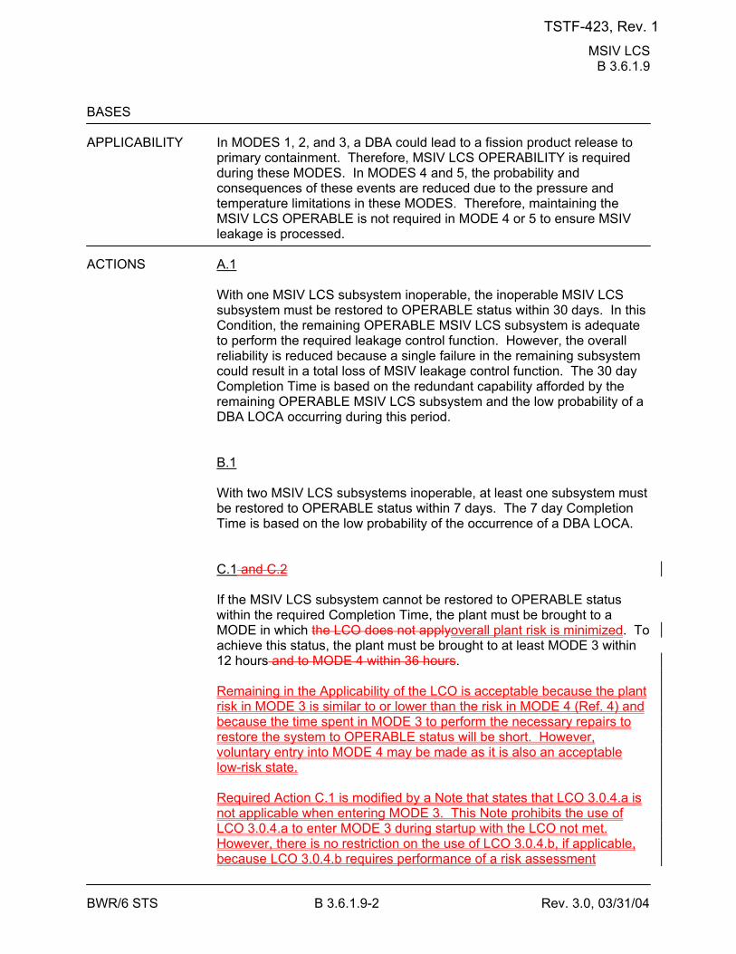
MSIV LCS B 3.6.1.9
BWR/6 STS B 3.6.1.9-2 Rev. 3.0, 03/31/04
BASES APPLICABILITY In MODES 1, 2, and 3, a DBA could lead to a fission product release to
primary containment. Therefore, MSIV LCS OPERABILITY is required during these MODES. In MODES 4 and 5, the probability and consequences of these events are reduced due to the pressure and temperature limitations in these MODES. Therefore, maintaining the MSIV LCS OPERABLE is not required in MODE 4 or 5 to ensure MSIV leakage is processed.
ACTIONS A.1
With one MSIV LCS subsystem inoperable, the inoperable MSIV LCS subsystem must be restored to OPERABLE status within 30 days. In this Condition, the remaining OPERABLE MSIV LCS subsystem is adequate to perform the required leakage control function. However, the overall reliability is reduced because a single failure in the remaining subsystem could result in a total loss of MSIV leakage control function. The 30 day Completion Time is based on the redundant capability afforded by the remaining OPERABLE MSIV LCS subsystem and the low probability of a DBA LOCA occurring during this period. B.1 With two MSIV LCS subsystems inoperable, at least one subsystem must be restored to OPERABLE status within 7 days. The 7 day Completion Time is based on the low probability of the occurrence of a DBA LOCA. C.1 and C.2 If the MSIV LCS subsystem cannot be restored to OPERABLE status within the required Completion Time, the plant must be brought to a MODE in which the LCO does not applyoverall plant risk is minimized. To achieve this status, the plant must be brought to at least MODE 3 within 12 hours and to MODE 4 within 36 hours. Remaining in the Applicability of the LCO is acceptable because the plant risk in MODE 3 is similar to or lower than the risk in MODE 4 (Ref. 4) and because the time spent in MODE 3 to perform the necessary repairs to restore the system to OPERABLE status will be short. However, voluntary entry into MODE 4 may be made as it is also an acceptable low-risk state. Required Action C.1 is modified by a Note that states that LCO 3.0.4.a is not applicable when entering MODE 3. This Note prohibits the use of LCO 3.0.4.a to enter MODE 3 during startup with the LCO not met. However, there is no restriction on the use of LCO 3.0.4.b, if applicable, because LCO 3.0.4.b requires performance of a risk assessment
TSTF-423, Rev. 1

MSIV LCS B 3.6.1.9
BWR/6 STS B 3.6.1.9-3 Rev. 3.0, 03/31/04
addressing inoperable systems and components, consideration of the results, determination of the acceptability of entering MODE 3, and establishment of risk management actions, if appropriate. LCO 3.0.4 is not applicable to, and the Note does not preclude, changes in MODES or other specified conditions in the Applicability that are required to comply with ACTIONS or that are part of a shutdown of the unit. The allowed Completion Times areis reasonable, based on operating experience, to reach the required plant conditions from full power conditions in an orderly manner and without challenging plant systems.
SURVEILLANCE SR 3.6.1.9.1 REQUIREMENTS
Each MSIV LCS blower is operated for ≥ [15] minutes to verify OPERABILITY. The 31 day Frequency was developed considering the known reliability of the LCS blower and controls, the two subsystem redundancy, and the low probability of a significant degradation of the MSIV LCS subsystem occurring between surveillances and has been shown to be acceptable through operating experience.
TSTF-423, Rev. 1
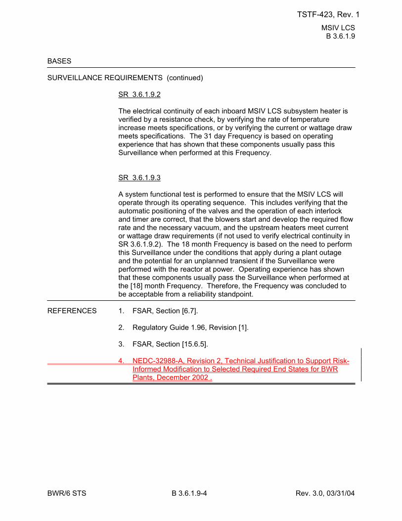
MSIV LCS B 3.6.1.9
BWR/6 STS B 3.6.1.9-4 Rev. 3.0, 03/31/04
BASES SURVEILLANCE REQUIREMENTS (continued)
SR 3.6.1.9.2 The electrical continuity of each inboard MSIV LCS subsystem heater is verified by a resistance check, by verifying the rate of temperature increase meets specifications, or by verifying the current or wattage draw meets specifications. The 31 day Frequency is based on operating experience that has shown that these components usually pass this Surveillance when performed at this Frequency. SR 3.6.1.9.3 A system functional test is performed to ensure that the MSIV LCS will operate through its operating sequence. This includes verifying that the automatic positioning of the valves and the operation of each interlock and timer are correct, that the blowers start and develop the required flow rate and the necessary vacuum, and the upstream heaters meet current or wattage draw requirements (if not used to verify electrical continuity in SR 3.6.1.9.2). The 18 month Frequency is based on the need to perform this Surveillance under the conditions that apply during a plant outage and the potential for an unplanned transient if the Surveillance were performed with the reactor at power. Operating experience has shown that these components usually pass the Surveillance when performed at the [18] month Frequency. Therefore, the Frequency was concluded to be acceptable from a reliability standpoint.
REFERENCES 1. FSAR, Section [6.7]. 2. Regulatory Guide 1.96, Revision [1]. 3. FSAR, Section [15.6.5]. 4. NEDC-32988-A, Revision 2, Technical Justification to Support Risk-
Informed Modification to Selected Required End States for BWR Plants, December 2002 .
TSTF-423, Rev. 1

RHR Suppression Pool Cooling B 3.6.2.3
BWR/6 STS B 3.6.2.3-2 Rev. 3.1, 12/01/05
BASES LCO During a DBA, a minimum of one RHR suppression pool cooling
subsystem is required to maintain the primary containment peak pressure and temperature below the design limits (Ref. 1). To ensure that these requirements are met, two RHR suppression pool cooling subsystems must be OPERABLE with power from two safety related independent power supplies. Therefore, in the event of an accident, at least one subsystem is OPERABLE, assuming the worst case single active failure. An RHR suppression pool cooling subsystem is OPERABLE when the pump, two heat exchangers, and associated piping, valves, instrumentation, and controls are OPERABLE.
APPLICABILITY In MODES 1, 2, and 3, a DBA could cause a release of radioactive
material to primary containment and cause a heatup and pressurization of primary containment. In MODES 4 and 5, the probability and consequences of these events are reduced due to the pressure and temperature limitations in these MODES. Therefore, the RHR Suppression Pool Cooling System is not required to be OPERABLE in MODE 4 or 5.
ACTIONS A.1
With one RHR suppression pool cooling subsystem inoperable, the inoperable subsystem must be restored to OPERABLE status within 7 days. In this Condition, the remaining RHR suppression pool cooling subsystem is adequate to perform the primary containment cooling function. However, the overall reliability is reduced because a single failure in the OPERABLE subsystem could result in reduced primary containment cooling capability. The 7 day Completion Time is acceptable in light of the redundant RHR suppression pool cooling capabilities afforded by the OPERABLE subsystem and the low probability of a DBA occurring during this period. B.1 If one RHR suppression pool cooling subsystem is inoperable and is not restored to OPERABLE status within the required Completion Time, the plant must be brought to a condition in which overall plant risk is minimized. To achieve this status, the plant must be brought to at least MODE 3 within 12 hours. Remaining in the Applicability of the LCO is acceptable because the plant risk in MODE 3 is similar to or lower than the risk in MODE 4 (Ref. 2) and because the time spent in MODE 3 to perform the necessary repairs to restore the system to OPERABLE status will be short. However, voluntary entry into MODE 4 may be made as it is also an acceptable low-risk state.
TSTF-423, Rev. 1

RHR Suppression Pool Cooling B 3.6.2.3
BWR/6 STS B 3.6.2.3-3 Rev. 3.1, 12/01/05
Required Action B.1 is modified by a Note that states that LCO 3.0.4.a is not applicable when entering MODE 3. This Note prohibits the use of LCO 3.0.4.a to enter MODE 3 during startup with the LCO not met. However, there is no restriction on the use of LCO 3.0.4.b, if applicable, because LCO 3.0.4.b requires performance of a risk assessment addressing inoperable systems and components, consideration of the results, determination of the acceptability of entering MODE 3, and establishment of risk management actions, if appropriate. LCO 3.0.4 is not applicable to, and the Note does not preclude, changes in MODES or other specified conditions in the Applicability that are required to comply with ACTIONS or that are part of a shutdown of the unit. The allowed Completion Time is reasonable, based on operating experience, to reach the required plant conditions from full power conditions in an orderly manner and without challenging plant systems. BC.1 With two RHR suppression pool cooling subsystems inoperable, one subsystem must be restored to OPERABLE status within 8 hours. In this condition, there is a substantial loss of the primary containment pressure and temperature mitigation function. The 8 hour Completion Time is based on this loss of function and is considered acceptable due to the low probability of a DBA and the potential avoidance of a plant shutdown transient that could result in the need for the RHR suppression pool cooling subsystems to operate.
TSTF-423, Rev. 1
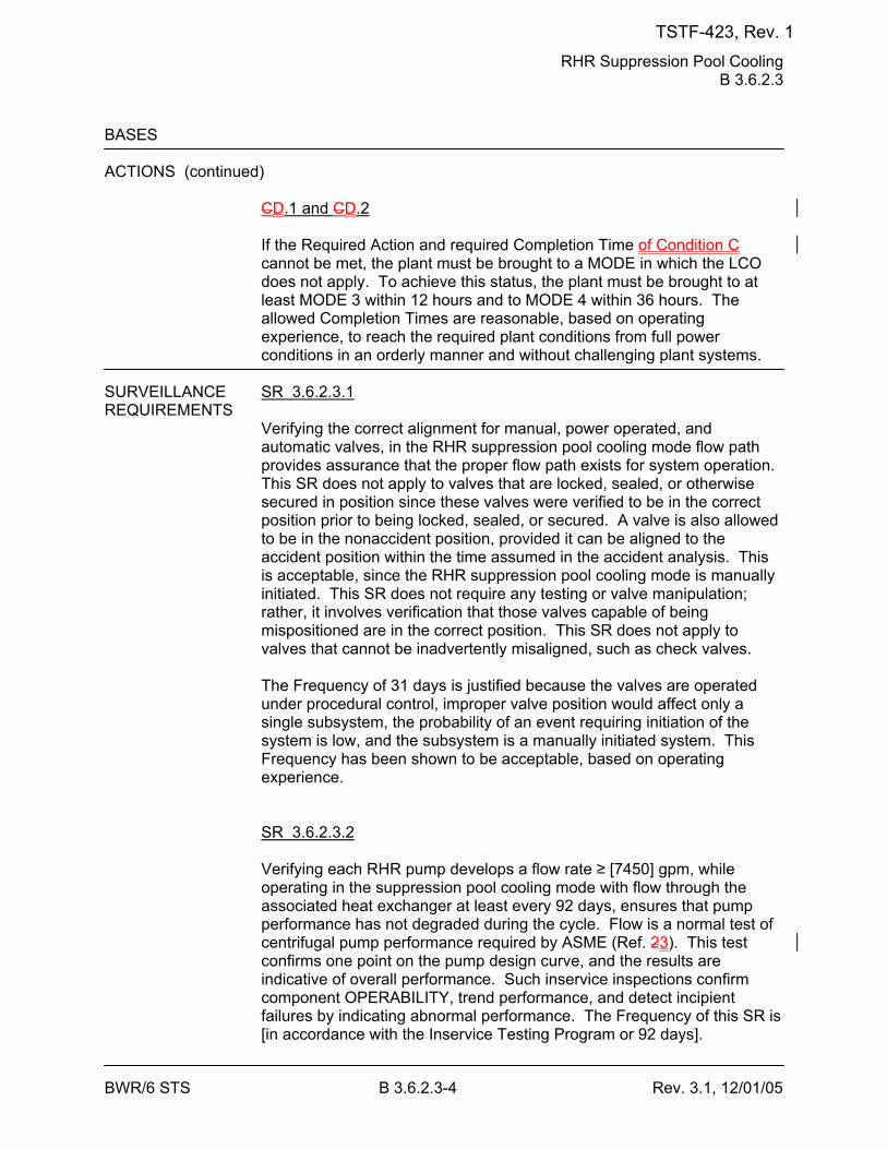
RHR Suppression Pool Cooling B 3.6.2.3
BWR/6 STS B 3.6.2.3-4 Rev. 3.1, 12/01/05
BASES ACTIONS (continued)
CD.1 and CD.2 If the Required Action and required Completion Time of Condition C cannot be met, the plant must be brought to a MODE in which the LCO does not apply. To achieve this status, the plant must be brought to at least MODE 3 within 12 hours and to MODE 4 within 36 hours. The allowed Completion Times are reasonable, based on operating experience, to reach the required plant conditions from full power conditions in an orderly manner and without challenging plant systems.
SURVEILLANCE SR 3.6.2.3.1 REQUIREMENTS
Verifying the correct alignment for manual, power operated, and automatic valves, in the RHR suppression pool cooling mode flow path provides assurance that the proper flow path exists for system operation. This SR does not apply to valves that are locked, sealed, or otherwise secured in position since these valves were verified to be in the correct position prior to being locked, sealed, or secured. A valve is also allowed to be in the nonaccident position, provided it can be aligned to the accident position within the time assumed in the accident analysis. This is acceptable, since the RHR suppression pool cooling mode is manually initiated. This SR does not require any testing or valve manipulation; rather, it involves verification that those valves capable of being mispositioned are in the correct position. This SR does not apply to valves that cannot be inadvertently misaligned, such as check valves. The Frequency of 31 days is justified because the valves are operated under procedural control, improper valve position would affect only a single subsystem, the probability of an event requiring initiation of the system is low, and the subsystem is a manually initiated system. This Frequency has been shown to be acceptable, based on operating experience. SR 3.6.2.3.2 Verifying each RHR pump develops a flow rate ≥ [7450] gpm, while operating in the suppression pool cooling mode with flow through the associated heat exchanger at least every 92 days, ensures that pump performance has not degraded during the cycle. Flow is a normal test of centrifugal pump performance required by ASME (Ref. 23). This test confirms one point on the pump design curve, and the results are indicative of overall performance. Such inservice inspections confirm component OPERABILITY, trend performance, and detect incipient failures by indicating abnormal performance. The Frequency of this SR is [in accordance with the Inservice Testing Program or 92 days].
TSTF-423, Rev. 1
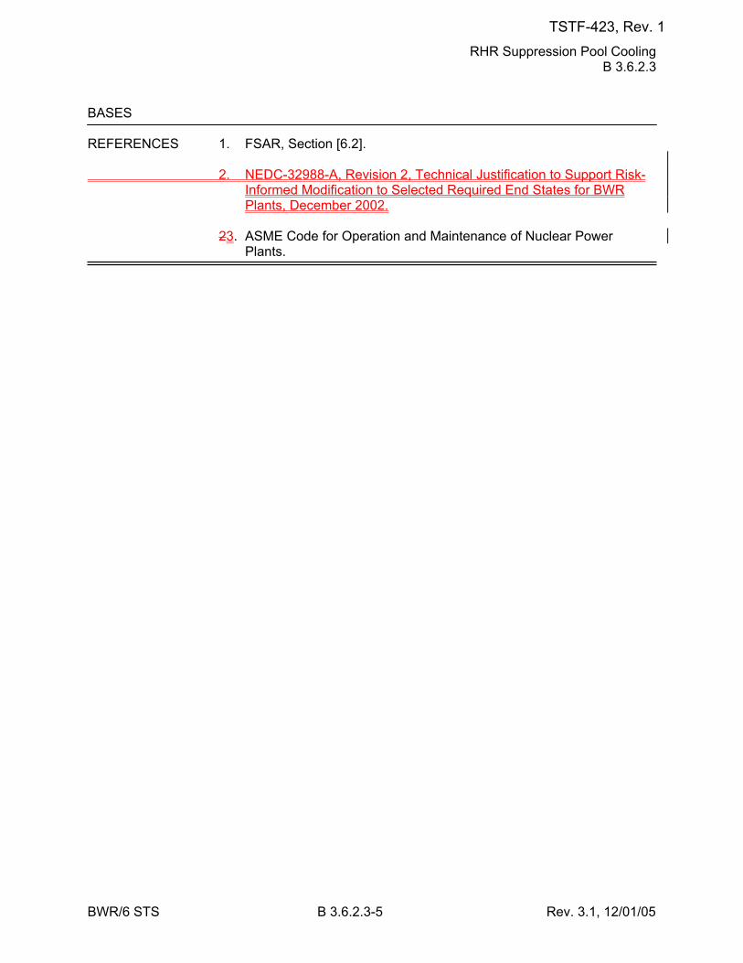
RHR Suppression Pool Cooling B 3.6.2.3
BWR/6 STS B 3.6.2.3-5 Rev. 3.1, 12/01/05
BASES REFERENCES 1. FSAR, Section [6.2]. 2. NEDC-32988-A, Revision 2, Technical Justification to Support Risk-
Informed Modification to Selected Required End States for BWR Plants, December 2002.
23. ASME Code for Operation and Maintenance of Nuclear Power
Plants.
TSTF-423, Rev. 1
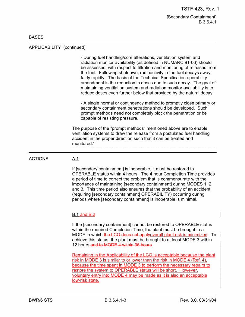
[Secondary Containment] B 3.6.4.1
BWR/6 STS B 3.6.4.1-3 Rev. 3.0, 03/31/04
BASES APPLICABILITY (continued)
- During fuel handling/core alterations, ventilation system and radiation monitor availability (as defined in NUMARC 91-06) should be assessed, with respect to filtration and monitoring of releases from the fuel. Following shutdown, radioactivity in the fuel decays away fairly rapidly. The basis of the Technical Specification operability amendment is the reduction in doses due to such decay. The goal of maintaining ventilation system and radiation monitor availability is to reduce doses even further below that provided by the natural decay. - A single normal or contingency method to promptly close primary or secondary containment penetrations should be developed. Such prompt methods need not completely block the penetration or be capable of resisting pressure.
The purpose of the "prompt methods" mentioned above are to enable ventilation systems to draw the release from a postulated fuel handling accident in the proper direction such that it can be treated and monitored." --------------------------------------------------------------------------------------------------
ACTIONS A.1
If [secondary containment] is inoperable, it must be restored to OPERABLE status within 4 hours. The 4 hour Completion Time provides a period of time to correct the problem that is commensurate with the importance of maintaining [secondary containment] during MODES 1, 2, and 3. This time period also ensures that the probability of an accident (requiring [secondary containment] OPERABILITY) occurring during periods where [secondary containment] is inoperable is minimal. B.1 and B.2 If the [secondary containment] cannot be restored to OPERABLE status within the required Completion Time, the plant must be brought to a MODE in which the LCO does not applyoverall plant risk is minimized. To achieve this status, the plant must be brought to at least MODE 3 within 12 hours and to MODE 4 within 36 hours. Remaining in the Applicability of the LCO is acceptable because the plant risk in MODE 3 is similar to or lower than the risk in MODE 4 (Ref. 4), because the time spent in MODE 3 to perform the necessary repairs to restore the system to OPERABLE status will be short. However, voluntary entry into MODE 4 may be made as it is also an acceptable low-risk state.
TSTF-423, Rev. 1
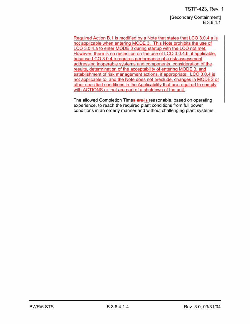
[Secondary Containment] B 3.6.4.1
BWR/6 STS B 3.6.4.1-4 Rev. 3.0, 03/31/04
Required Action B.1 is modified by a Note that states that LCO 3.0.4.a is not applicable when entering MODE 3. This Note prohibits the use of LCO 3.0.4.a to enter MODE 3 during startup with the LCO not met. However, there is no restriction on the use of LCO 3.0.4.b, if applicable, because LCO 3.0.4.b requires performance of a risk assessment addressing inoperable systems and components, consideration of the results, determination of the acceptability of entering MODE 3, and establishment of risk management actions, if appropriate. LCO 3.0.4 is not applicable to, and the Note does not preclude, changes in MODES or other specified conditions in the Applicability that are required to comply with ACTIONS or that are part of a shutdown of the unit. The allowed Completion Times are is reasonable, based on operating experience, to reach the required plant conditions from full power conditions in an orderly manner and without challenging plant systems.
TSTF-423, Rev. 1
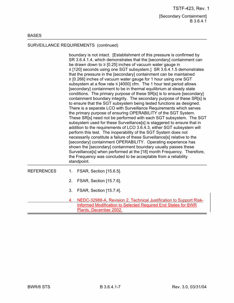
[Secondary Containment] B 3.6.4.1
BWR/6 STS B 3.6.4.1-7 Rev. 3.0, 03/31/04
BASES SURVEILLANCE REQUIREMENTS (continued)
boundary is not intact. [Establishment of this pressure is confirmed by SR 3.6.4.1.4, which demonstrates that the [secondary] containment can be drawn down to ≥ [0.25] inches of vacuum water gauge in ≤ [120] seconds using one SGT subsystem.] SR 3.6.4.1.5 demonstrates that the pressure in the [secondary] containment can be maintained ≥ [0.266] inches of vacuum water gauge for 1 hour using one SGT subsystem at a flow rate ≤ [4000] cfm. The 1 hour test period allows [secondary] containment to be in thermal equilibrium at steady state conditions. The primary purpose of these SR[s] is to ensure [secondary] containment boundary integrity. The secondary purpose of these SR[s] is to ensure that the SGT subsystem being tested functions as designed. There is a separate LCO with Surveillance Requirements which serves the primary purpose of ensuring OPERABILITY of the SGT System. These SR[s] need not be performed with each SGT subsystem. The SGT subsystem used for these Surveillance[s] is staggered to ensure that in addition to the requirements of LCO 3.6.4.3, either SGT subsystem will perform this test. The inoperability of the SGT System does not necessarily constitute a failure of these Surveillance[s] relative to the [secondary] containment OPERABILITY. Operating experience has shown the [secondary] containment boundary usually passes these Surveillance[s] when performed at the [18] month Frequency. Therefore, the Frequency was concluded to be acceptable from a reliability standpoint.
REFERENCES 1. FSAR, Section [15.6.5]. 2. FSAR, Section [15.7.6]. 3. FSAR, Section [15.7.4]. 4. NEDC-32988-A, Revision 2, Technical Justification to Support Risk-
Informed Modification to Selected Required End States for BWR Plants, December 2002.
TSTF-423, Rev. 1
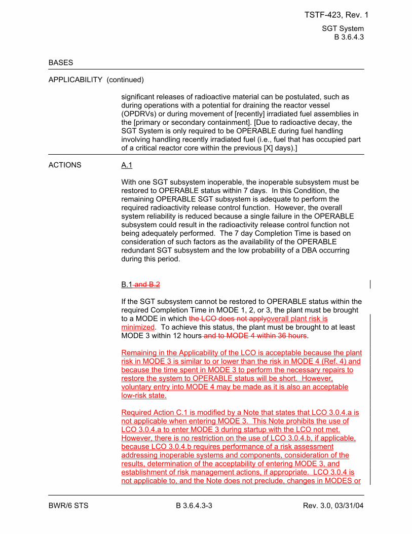
SGT System B 3.6.4.3
BWR/6 STS B 3.6.4.3-3 Rev. 3.0, 03/31/04
BASES APPLICABILITY (continued)
significant releases of radioactive material can be postulated, such as during operations with a potential for draining the reactor vessel (OPDRVs) or during movement of [recently] irradiated fuel assemblies in the [primary or secondary containment]. [Due to radioactive decay, the SGT System is only required to be OPERABLE during fuel handling involving handling recently irradiated fuel (i.e., fuel that has occupied part of a critical reactor core within the previous [X] days).]
ACTIONS A.1
With one SGT subsystem inoperable, the inoperable subsystem must be restored to OPERABLE status within 7 days. In this Condition, the remaining OPERABLE SGT subsystem is adequate to perform the required radioactivity release control function. However, the overall system reliability is reduced because a single failure in the OPERABLE subsystem could result in the radioactivity release control function not being adequately performed. The 7 day Completion Time is based on consideration of such factors as the availability of the OPERABLE redundant SGT subsystem and the low probability of a DBA occurring during this period. B.1 and B.2 If the SGT subsystem cannot be restored to OPERABLE status within the required Completion Time in MODE 1, 2, or 3, the plant must be brought to a MODE in which the LCO does not applyoverall plant risk is minimized. To achieve this status, the plant must be brought to at least MODE 3 within 12 hours and to MODE 4 within 36 hours. Remaining in the Applicability of the LCO is acceptable because the plant risk in MODE 3 is similar to or lower than the risk in MODE 4 (Ref. 4) and because the time spent in MODE 3 to perform the necessary repairs to restore the system to OPERABLE status will be short. However, voluntary entry into MODE 4 may be made as it is also an acceptable low-risk state. Required Action C.1 is modified by a Note that states that LCO 3.0.4.a is not applicable when entering MODE 3. This Note prohibits the use of LCO 3.0.4.a to enter MODE 3 during startup with the LCO not met. However, there is no restriction on the use of LCO 3.0.4.b, if applicable, because LCO 3.0.4.b requires performance of a risk assessment addressing inoperable systems and components, consideration of the results, determination of the acceptability of entering MODE 3, and establishment of risk management actions, if appropriate. LCO 3.0.4 is not applicable to, and the Note does not preclude, changes in MODES or
TSTF-423, Rev. 1
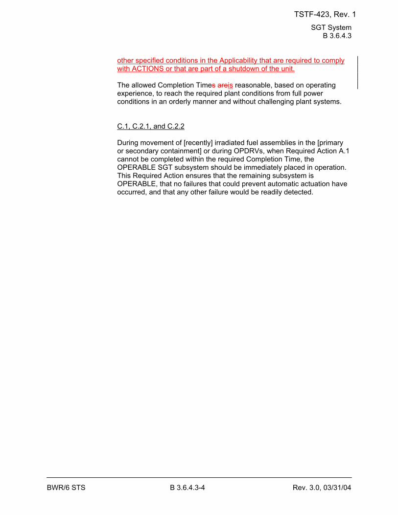
SGT System B 3.6.4.3
BWR/6 STS B 3.6.4.3-4 Rev. 3.0, 03/31/04
other specified conditions in the Applicability that are required to comply with ACTIONS or that are part of a shutdown of the unit. The allowed Completion Times areis reasonable, based on operating experience, to reach the required plant conditions from full power conditions in an orderly manner and without challenging plant systems. C.1, C.2.1, and C.2.2 During movement of [recently] irradiated fuel assemblies in the [primary or secondary containment] or during OPDRVs, when Required Action A.1 cannot be completed within the required Completion Time, the OPERABLE SGT subsystem should be immediately placed in operation. This Required Action ensures that the remaining subsystem is OPERABLE, that no failures that could prevent automatic actuation have occurred, and that any other failure would be readily detected.
TSTF-423, Rev. 1
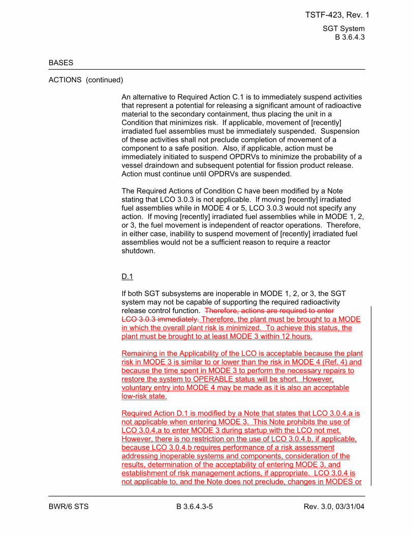
SGT System B 3.6.4.3
BWR/6 STS B 3.6.4.3-5 Rev. 3.0, 03/31/04
BASES ACTIONS (continued)
An alternative to Required Action C.1 is to immediately suspend activities that represent a potential for releasing a significant amount of radioactive material to the secondary containment, thus placing the unit in a Condition that minimizes risk. If applicable, movement of [recently] irradiated fuel assemblies must be immediately suspended. Suspension of these activities shall not preclude completion of movement of a component to a safe position. Also, if applicable, action must be immediately initiated to suspend OPDRVs to minimize the probability of a vessel draindown and subsequent potential for fission product release. Action must continue until OPDRVs are suspended. The Required Actions of Condition C have been modified by a Note stating that LCO 3.0.3 is not applicable. If moving [recently] irradiated fuel assemblies while in MODE 4 or 5, LCO 3.0.3 would not specify any action. If moving [recently] irradiated fuel assemblies while in MODE 1, 2, or 3, the fuel movement is independent of reactor operations. Therefore, in either case, inability to suspend movement of [recently] irradiated fuel assemblies would not be a sufficient reason to require a reactor shutdown. D.1 If both SGT subsystems are inoperable in MODE 1, 2, or 3, the SGT system may not be capable of supporting the required radioactivity release control function. Therefore, actions are required to enter LCO 3.0.3 immediately. Therefore, the plant must be brought to a MODE in which the overall plant risk is minimized. To achieve this status, the plant must be brought to at least MODE 3 within 12 hours. Remaining in the Applicability of the LCO is acceptable because the plant risk in MODE 3 is similar to or lower than the risk in MODE 4 (Ref. 4) and because the time spent in MODE 3 to perform the necessary repairs to restore the system to OPERABLE status will be short. However, voluntary entry into MODE 4 may be made as it is also an acceptable low-risk state. Required Action D.1 is modified by a Note that states that LCO 3.0.4.a is not applicable when entering MODE 3. This Note prohibits the use of LCO 3.0.4.a to enter MODE 3 during startup with the LCO not met. However, there is no restriction on the use of LCO 3.0.4.b, if applicable, because LCO 3.0.4.b requires performance of a risk assessment addressing inoperable systems and components, consideration of the results, determination of the acceptability of entering MODE 3, and establishment of risk management actions, if appropriate. LCO 3.0.4 is not applicable to, and the Note does not preclude, changes in MODES or
TSTF-423, Rev. 1
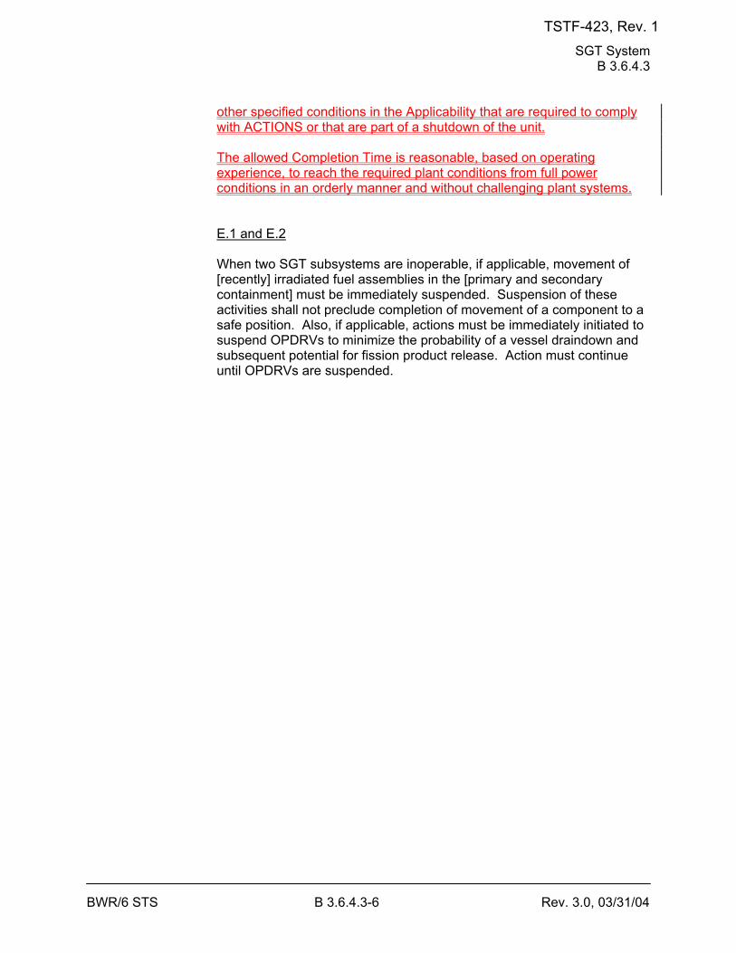
SGT System B 3.6.4.3
BWR/6 STS B 3.6.4.3-6 Rev. 3.0, 03/31/04
other specified conditions in the Applicability that are required to comply with ACTIONS or that are part of a shutdown of the unit. The allowed Completion Time is reasonable, based on operating experience, to reach the required plant conditions from full power conditions in an orderly manner and without challenging plant systems. E.1 and E.2 When two SGT subsystems are inoperable, if applicable, movement of [recently] irradiated fuel assemblies in the [primary and secondary containment] must be immediately suspended. Suspension of these activities shall not preclude completion of movement of a component to a safe position. Also, if applicable, actions must be immediately initiated to suspend OPDRVs to minimize the probability of a vessel draindown and subsequent potential for fission product release. Action must continue until OPDRVs are suspended.
TSTF-423, Rev. 1
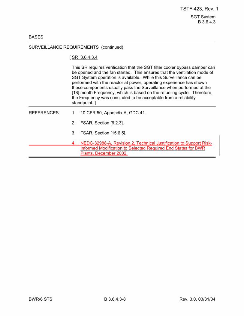
SGT System B 3.6.4.3
BWR/6 STS B 3.6.4.3-8 Rev. 3.0, 03/31/04
BASES SURVEILLANCE REQUIREMENTS (continued)
[ SR 3.6.4.3.4 This SR requires verification that the SGT filter cooler bypass damper can be opened and the fan started. This ensures that the ventilation mode of SGT System operation is available. While this Surveillance can be performed with the reactor at power, operating experience has shown these components usually pass the Surveillance when performed at the [18] month Frequency, which is based on the refueling cycle. Therefore, the Frequency was concluded to be acceptable from a reliability standpoint. ]
REFERENCES 1. 10 CFR 50, Appendix A, GDC 41. 2. FSAR, Section [6.2.3]. 3. FSAR, Section [15.6.5]. 4. NEDC-32988-A, Revision 2, Technical Justification to Support Risk-
Informed Modification to Selected Required End States for BWR Plants, December 2002.
TSTF-423, Rev. 1
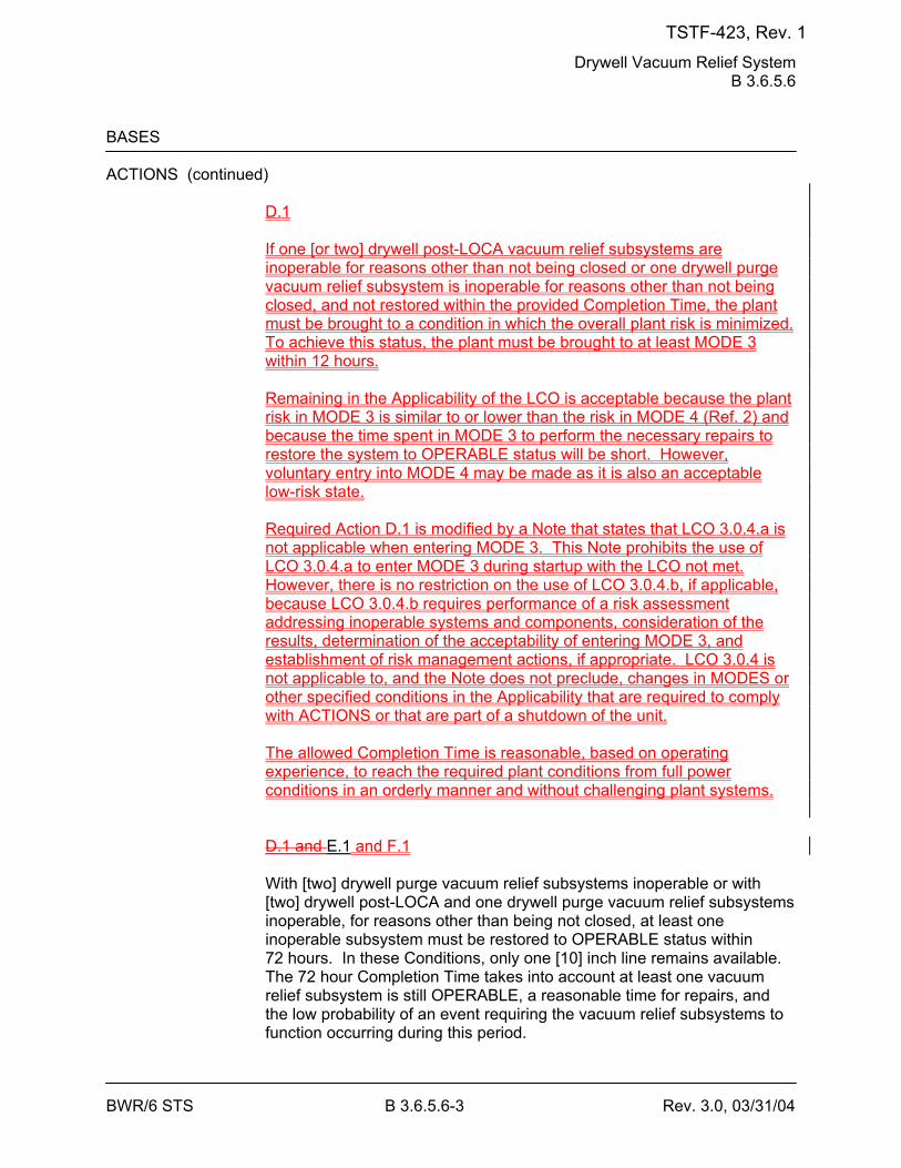
Drywell Vacuum Relief System B 3.6.5.6
BWR/6 STS B 3.6.5.6-3 Rev. 3.0, 03/31/04
BASES ACTIONS (continued)
D.1 If one [or two] drywell post-LOCA vacuum relief subsystems are inoperable for reasons other than not being closed or one drywell purge vacuum relief subsystem is inoperable for reasons other than not being closed, and not restored within the provided Completion Time, the plant must be brought to a condition in which the overall plant risk is minimized. To achieve this status, the plant must be brought to at least MODE 3 within 12 hours. Remaining in the Applicability of the LCO is acceptable because the plant risk in MODE 3 is similar to or lower than the risk in MODE 4 (Ref. 2) and because the time spent in MODE 3 to perform the necessary repairs to restore the system to OPERABLE status will be short. However, voluntary entry into MODE 4 may be made as it is also an acceptable low-risk state. Required Action D.1 is modified by a Note that states that LCO 3.0.4.a is not applicable when entering MODE 3. This Note prohibits the use of LCO 3.0.4.a to enter MODE 3 during startup with the LCO not met. However, there is no restriction on the use of LCO 3.0.4.b, if applicable, because LCO 3.0.4.b requires performance of a risk assessment addressing inoperable systems and components, consideration of the results, determination of the acceptability of entering MODE 3, and establishment of risk management actions, if appropriate. LCO 3.0.4 is not applicable to, and the Note does not preclude, changes in MODES or other specified conditions in the Applicability that are required to comply with ACTIONS or that are part of a shutdown of the unit. The allowed Completion Time is reasonable, based on operating experience, to reach the required plant conditions from full power conditions in an orderly manner and without challenging plant systems. D.1 and E.1 and F.1 With [two] drywell purge vacuum relief subsystems inoperable or with [two] drywell post-LOCA and one drywell purge vacuum relief subsystems inoperable, for reasons other than being not closed, at least one inoperable subsystem must be restored to OPERABLE status within 72 hours. In these Conditions, only one [10] inch line remains available. The 72 hour Completion Time takes into account at least one vacuum relief subsystem is still OPERABLE, a reasonable time for repairs, and the low probability of an event requiring the vacuum relief subsystems to function occurring during this period.
TSTF-423, Rev. 1
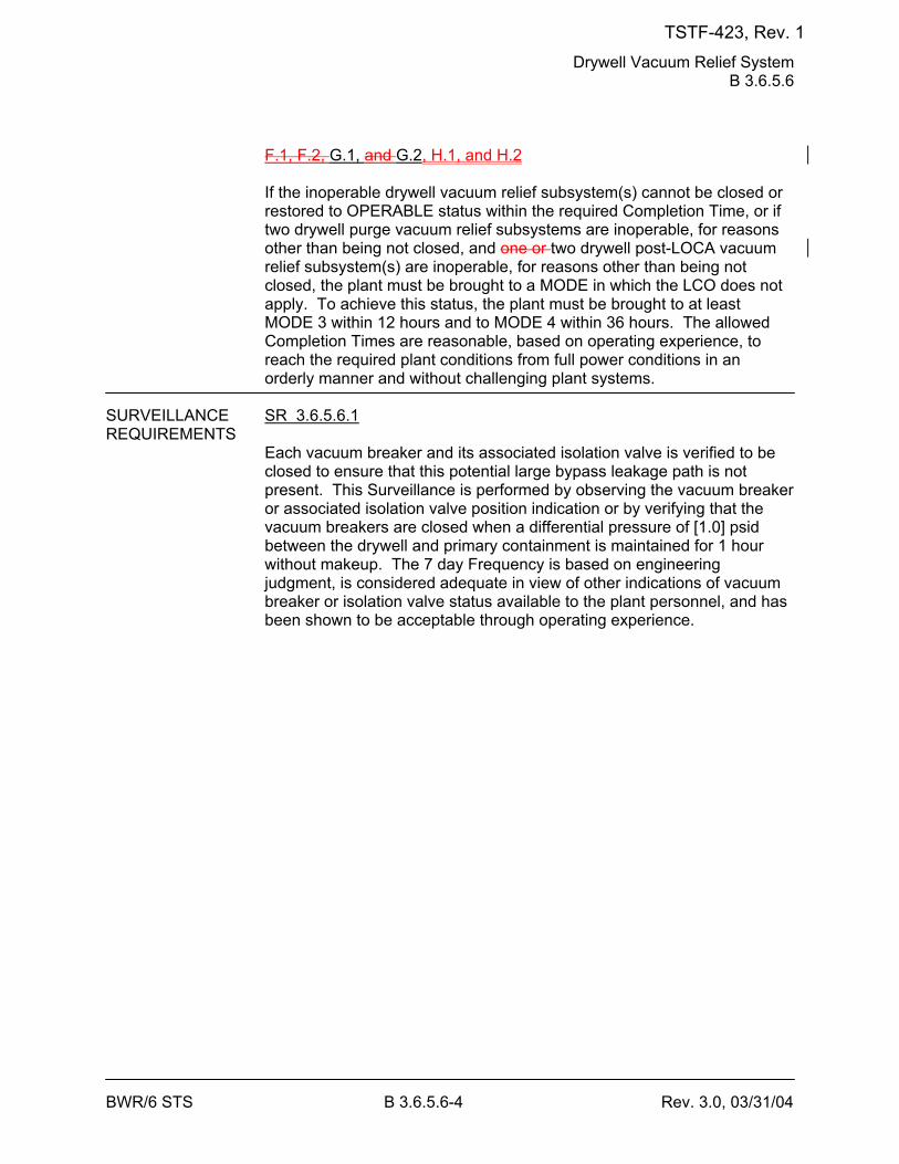
Drywell Vacuum Relief System B 3.6.5.6
BWR/6 STS B 3.6.5.6-4 Rev. 3.0, 03/31/04
F.1, F.2, G.1, and G.2, H.1, and H.2 If the inoperable drywell vacuum relief subsystem(s) cannot be closed or restored to OPERABLE status within the required Completion Time, or if two drywell purge vacuum relief subsystems are inoperable, for reasons other than being not closed, and one or two drywell post-LOCA vacuum relief subsystem(s) are inoperable, for reasons other than being not closed, the plant must be brought to a MODE in which the LCO does not apply. To achieve this status, the plant must be brought to at least MODE 3 within 12 hours and to MODE 4 within 36 hours. The allowed Completion Times are reasonable, based on operating experience, to reach the required plant conditions from full power conditions in an orderly manner and without challenging plant systems.
SURVEILLANCE SR 3.6.5.6.1 REQUIREMENTS
Each vacuum breaker and its associated isolation valve is verified to be closed to ensure that this potential large bypass leakage path is not present. This Surveillance is performed by observing the vacuum breaker or associated isolation valve position indication or by verifying that the vacuum breakers are closed when a differential pressure of [1.0] psid between the drywell and primary containment is maintained for 1 hour without makeup. The 7 day Frequency is based on engineering judgment, is considered adequate in view of other indications of vacuum breaker or isolation valve status available to the plant personnel, and has been shown to be acceptable through operating experience.
TSTF-423, Rev. 1
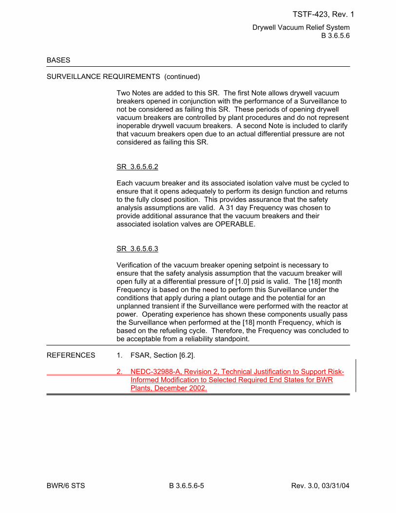
Drywell Vacuum Relief System B 3.6.5.6
BWR/6 STS B 3.6.5.6-5 Rev. 3.0, 03/31/04
BASES SURVEILLANCE REQUIREMENTS (continued)
Two Notes are added to this SR. The first Note allows drywell vacuum breakers opened in conjunction with the performance of a Surveillance to not be considered as failing this SR. These periods of opening drywell vacuum breakers are controlled by plant procedures and do not represent inoperable drywell vacuum breakers. A second Note is included to clarify that vacuum breakers open due to an actual differential pressure are not considered as failing this SR. SR 3.6.5.6.2 Each vacuum breaker and its associated isolation valve must be cycled to ensure that it opens adequately to perform its design function and returns to the fully closed position. This provides assurance that the safety analysis assumptions are valid. A 31 day Frequency was chosen to provide additional assurance that the vacuum breakers and their associated isolation valves are OPERABLE. SR 3.6.5.6.3 Verification of the vacuum breaker opening setpoint is necessary to ensure that the safety analysis assumption that the vacuum breaker will open fully at a differential pressure of [1.0] psid is valid. The [18] month Frequency is based on the need to perform this Surveillance under the conditions that apply during a plant outage and the potential for an unplanned transient if the Surveillance were performed with the reactor at power. Operating experience has shown these components usually pass the Surveillance when performed at the [18] month Frequency, which is based on the refueling cycle. Therefore, the Frequency was concluded to be acceptable from a reliability standpoint.
REFERENCES 1. FSAR, Section [6.2]. 2. NEDC-32988-A, Revision 2, Technical Justification to Support Risk-
Informed Modification to Selected Required End States for BWR Plants, December 2002.
TSTF-423, Rev. 1
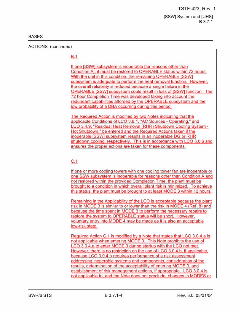
[SSW] System and [UHS] B 3.7.1
BWR/6 STS B 3.7.1-4 Rev. 3.0, 03/31/04
BASES ACTIONS (continued)
B.1 If one [SSW] subsystem is inoperable [for reasons other than Condition A], it must be restored to OPERABLE status within 72 hours. With the unit in this condition, the remaining OPERABLE [SSW] subsystem is adequate to perform the heat removal function. However, the overall reliability is reduced because a single failure in the OPERABLE [SSW] subsystem could result in loss of [SSW] function. The 72 hour Completion Time was developed taking into account the redundant capabilities afforded by the OPERABLE subsystem and the low probability of a DBA occurring during this period. The Required Action is modified by two Notes indicating that the applicable Conditions of LCO 3.8.1, "AC Sources - Operating," and LCO 3.4.9, "Residual Heat Removal (RHR) Shutdown Cooling System - Hot Shutdown," be entered and the Required Actions taken if the inoperable [SSW] subsystem results in an inoperable DG or RHR shutdown cooling, respectively. This is in accordance with LCO 3.0.6 and ensures the proper actions are taken for these components. C.1 If one or more cooling towers with one cooling tower fan are inoperable or one SSW subsystem is inoperable for reasons other than Condition A and not restored within the provided Completion Time, the plant must be brought to a condition in which overall plant risk is minimized. To achieve this status, the plant must be brought to at least MODE 3 within 12 hours. Remaining in the Applicability of the LCO is acceptable because the plant risk in MODE 3 is similar to or lower than the risk in MODE 4 (Ref. 8) and because the time spent in MODE 3 to perform the necessary repairs to restore the system to OPERABLE status will be short. However, voluntary entry into MODE 4 may be made as it is also an acceptable low-risk state. Required Action C.1 is modified by a Note that states that LCO 3.0.4.a is not applicable when entering MODE 3. This Note prohibits the use of LCO 3.0.4.a to enter MODE 3 during startup with the LCO not met. However, there is no restriction on the use of LCO 3.0.4.b, if applicable, because LCO 3.0.4.b requires performance of a risk assessment addressing inoperable systems and components, consideration of the results, determination of the acceptability of entering MODE 3, and establishment of risk management actions, if appropriate. LCO 3.0.4 is not applicable to, and the Note does not preclude, changes in MODES or
TSTF-423, Rev. 1
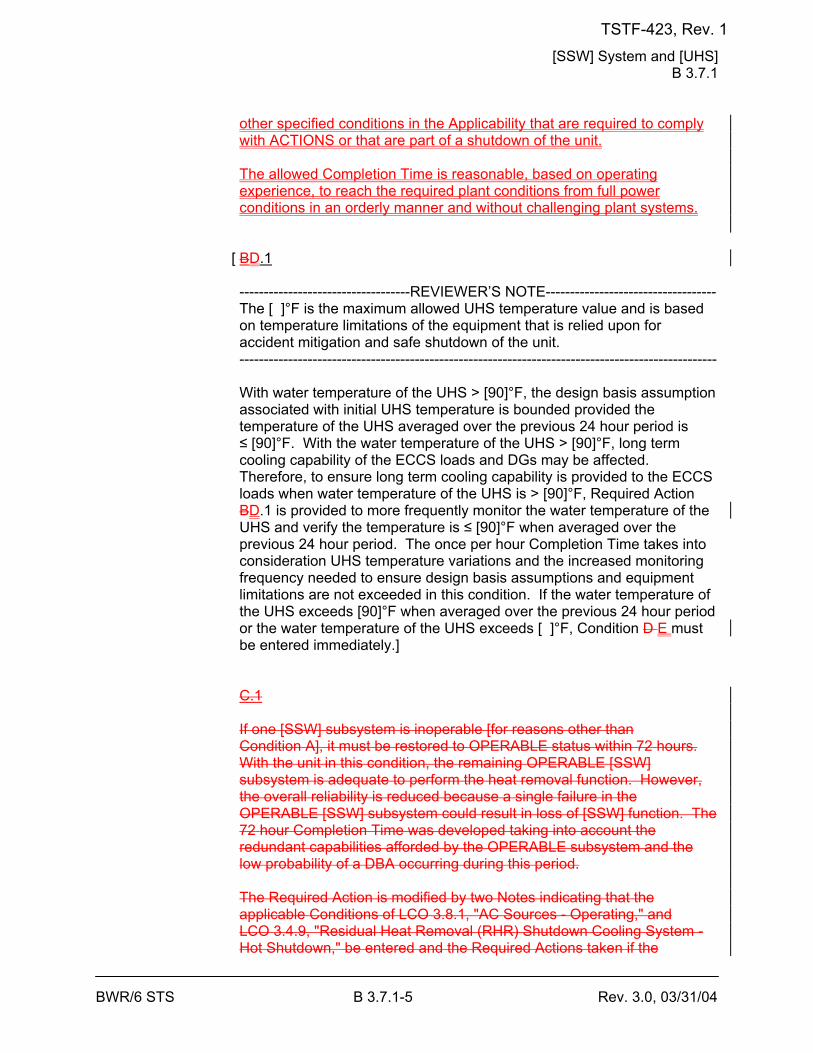
[SSW] System and [UHS] B 3.7.1
BWR/6 STS B 3.7.1-5 Rev. 3.0, 03/31/04
other specified conditions in the Applicability that are required to comply with ACTIONS or that are part of a shutdown of the unit. The allowed Completion Time is reasonable, based on operating experience, to reach the required plant conditions from full power conditions in an orderly manner and without challenging plant systems.
[ BD.1 -----------------------------------REVIEWER’S NOTE----------------------------------- The [ ]°F is the maximum allowed UHS temperature value and is based on temperature limitations of the equipment that is relied upon for accident mitigation and safe shutdown of the unit. -------------------------------------------------------------------------------------------------- With water temperature of the UHS > [90]°F, the design basis assumption associated with initial UHS temperature is bounded provided the temperature of the UHS averaged over the previous 24 hour period is ≤ [90]°F. With the water temperature of the UHS > [90]°F, long term cooling capability of the ECCS loads and DGs may be affected. Therefore, to ensure long term cooling capability is provided to the ECCS loads when water temperature of the UHS is > [90]°F, Required Action BD.1 is provided to more frequently monitor the water temperature of the UHS and verify the temperature is ≤ [90]°F when averaged over the previous 24 hour period. The once per hour Completion Time takes into consideration UHS temperature variations and the increased monitoring frequency needed to ensure design basis assumptions and equipment limitations are not exceeded in this condition. If the water temperature of the UHS exceeds [90]°F when averaged over the previous 24 hour period or the water temperature of the UHS exceeds [ ]°F, Condition D E must be entered immediately.] C.1 If one [SSW] subsystem is inoperable [for reasons other than Condition A], it must be restored to OPERABLE status within 72 hours. With the unit in this condition, the remaining OPERABLE [SSW] subsystem is adequate to perform the heat removal function. However, the overall reliability is reduced because a single failure in the OPERABLE [SSW] subsystem could result in loss of [SSW] function. The 72 hour Completion Time was developed taking into account the redundant capabilities afforded by the OPERABLE subsystem and the low probability of a DBA occurring during this period. The Required Action is modified by two Notes indicating that the applicable Conditions of LCO 3.8.1, "AC Sources - Operating," and LCO 3.4.9, "Residual Heat Removal (RHR) Shutdown Cooling System - Hot Shutdown," be entered and the Required Actions taken if the
TSTF-423, Rev. 1
[SSW] System and [UHS] B 3.7.1
BWR/6 STS B 3.7.1-6 Rev. 3.0, 03/31/04
inoperable [SSW] subsystem results in an inoperable DG or RHR shutdown cooling, respectively. This is in accordance with LCO 3.0.6 and ensures the proper actions are taken for these components.
TSTF-423, Rev. 1
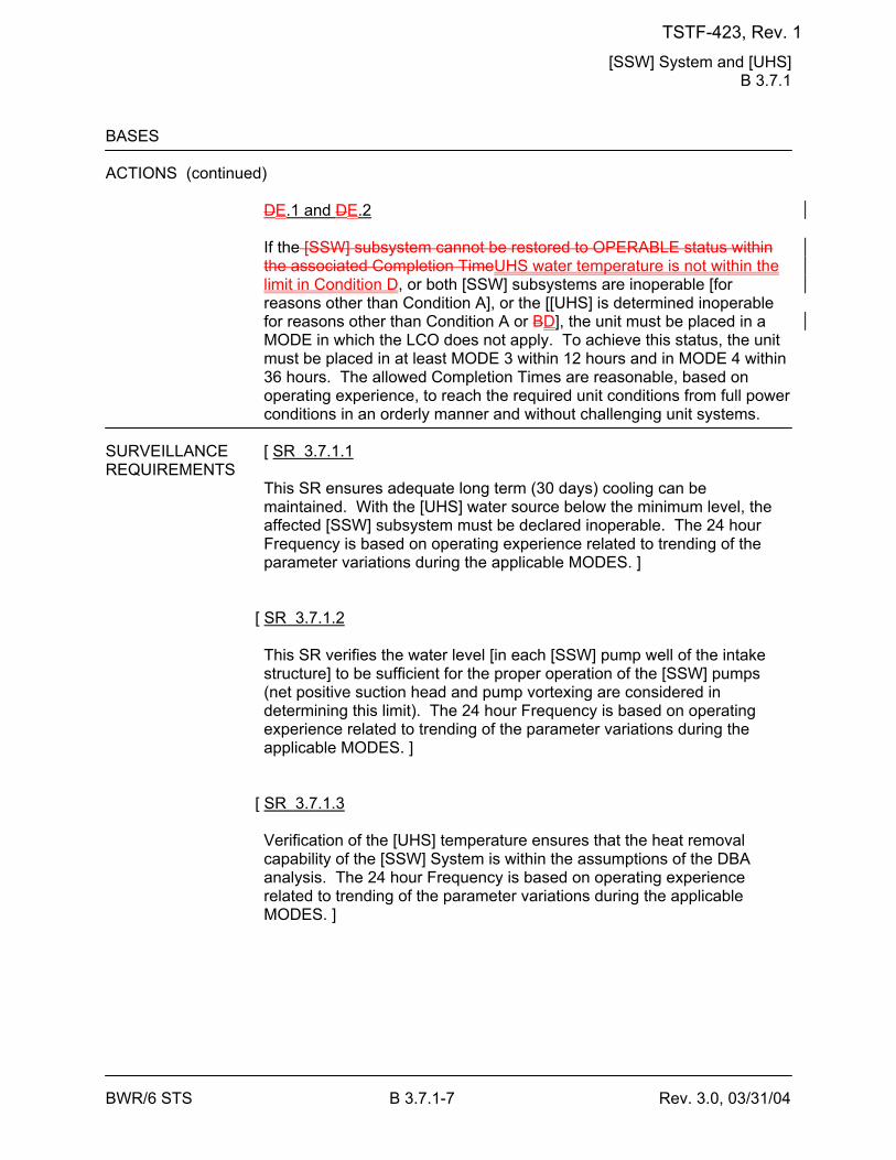
[SSW] System and [UHS] B 3.7.1
BWR/6 STS B 3.7.1-7 Rev. 3.0, 03/31/04
BASES ACTIONS (continued)
DE.1 and DE.2 If the [SSW] subsystem cannot be restored to OPERABLE status within the associated Completion TimeUHS water temperature is not within the limit in Condition D, or both [SSW] subsystems are inoperable [for reasons other than Condition A], or the [[UHS] is determined inoperable for reasons other than Condition A or BD], the unit must be placed in a MODE in which the LCO does not apply. To achieve this status, the unit must be placed in at least MODE 3 within 12 hours and in MODE 4 within 36 hours. The allowed Completion Times are reasonable, based on operating experience, to reach the required unit conditions from full power conditions in an orderly manner and without challenging unit systems.
SURVEILLANCE [ SR 3.7.1.1 REQUIREMENTS
This SR ensures adequate long term (30 days) cooling can be maintained. With the [UHS] water source below the minimum level, the affected [SSW] subsystem must be declared inoperable. The 24 hour Frequency is based on operating experience related to trending of the parameter variations during the applicable MODES. ]
[ SR 3.7.1.2 This SR verifies the water level [in each [SSW] pump well of the intake structure] to be sufficient for the proper operation of the [SSW] pumps (net positive suction head and pump vortexing are considered in determining this limit). The 24 hour Frequency is based on operating experience related to trending of the parameter variations during the applicable MODES. ]
[ SR 3.7.1.3 Verification of the [UHS] temperature ensures that the heat removal capability of the [SSW] System is within the assumptions of the DBA analysis. The 24 hour Frequency is based on operating experience related to trending of the parameter variations during the applicable MODES. ]
TSTF-423, Rev. 1
[SSW] System and [UHS] B 3.7.1
BWR/6 STS B 3.7.1-9 Rev. 3.0, 03/31/04
BASES SURVEILLANCE REQUIREMENTS (continued)
SR 3.7.1.6 This SR verifies that the automatic isolation valves of the [SSW] System will automatically switch to the safety or emergency position to provide cooling water exclusively to the safety related equipment during an accident event. This is demonstrated by use of an actual or simulated initiation signal. This SR also verifies the automatic start capability of the [SSW] pump and cooling tower fans in each subsystem. The LOGIC SYSTEM FUNCTIONAL TEST in SR 3.3.5.1.6 overlaps this SR to provide complete testing of the safety function. Operating experience has shown that these components usually pass the SR when performed on the [18] month Frequency. Therefore, this Frequency is concluded to be acceptable from a reliability standpoint.
REFERENCES 1. Regulatory Guide 1.27, Revision 2, January 1976. 2. FSAR, Section [9.2.1]. 3. FSAR, Table [9.2-3]. 4. FSAR, Section [6.2.1.1.3.3.1.6]. 5. FSAR, Chapter [15]. 6. FSAR, Section [6.2.2.3]. 7. FSAR, Table [6.2-2]. 8. NEDC-32988-A, Revision 2, Technical Justification to Support Risk-
Informed Modification to Selected Required End States for BWR Plants, December 2002.
TSTF-423, Rev. 1
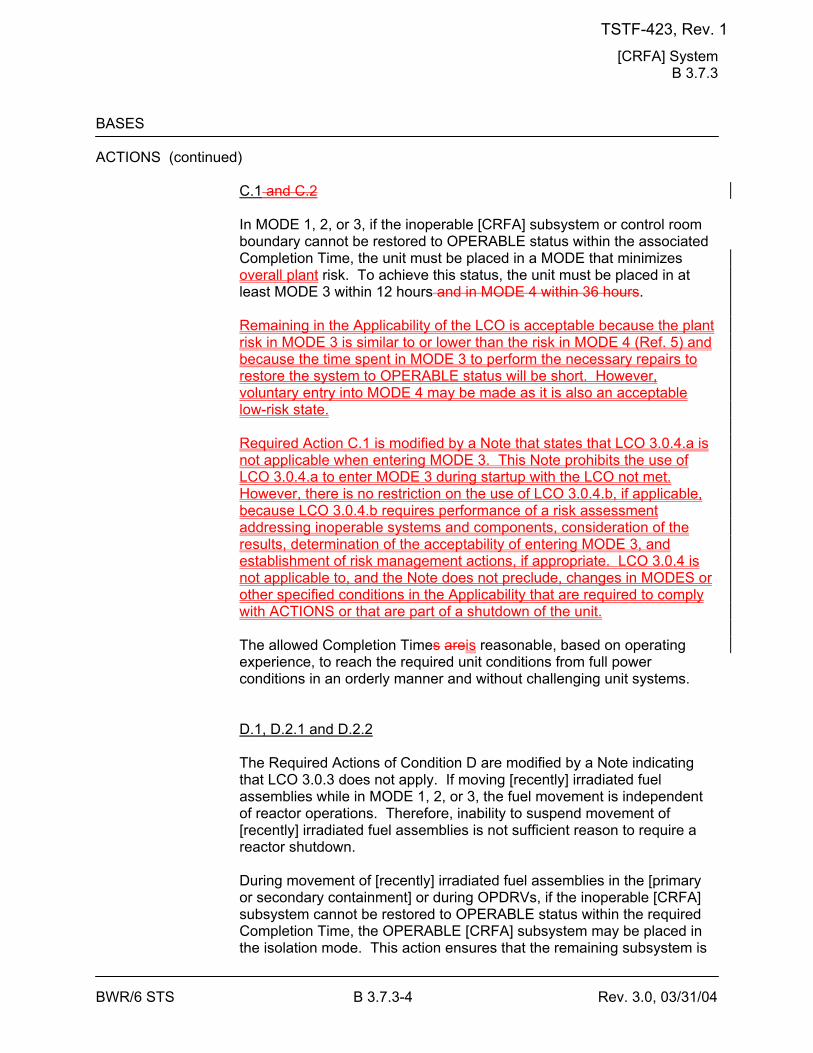
[CRFA] System B 3.7.3
BWR/6 STS B 3.7.3-4 Rev. 3.0, 03/31/04
BASES ACTIONS (continued)
C.1 and C.2 In MODE 1, 2, or 3, if the inoperable [CRFA] subsystem or control room boundary cannot be restored to OPERABLE status within the associated Completion Time, the unit must be placed in a MODE that minimizes overall plant risk. To achieve this status, the unit must be placed in at least MODE 3 within 12 hours and in MODE 4 within 36 hours. Remaining in the Applicability of the LCO is acceptable because the plant risk in MODE 3 is similar to or lower than the risk in MODE 4 (Ref. 5) and because the time spent in MODE 3 to perform the necessary repairs to restore the system to OPERABLE status will be short. However, voluntary entry into MODE 4 may be made as it is also an acceptable low-risk state. Required Action C.1 is modified by a Note that states that LCO 3.0.4.a is not applicable when entering MODE 3. This Note prohibits the use of LCO 3.0.4.a to enter MODE 3 during startup with the LCO not met. However, there is no restriction on the use of LCO 3.0.4.b, if applicable, because LCO 3.0.4.b requires performance of a risk assessment addressing inoperable systems and components, consideration of the results, determination of the acceptability of entering MODE 3, and establishment of risk management actions, if appropriate. LCO 3.0.4 is not applicable to, and the Note does not preclude, changes in MODES or other specified conditions in the Applicability that are required to comply with ACTIONS or that are part of a shutdown of the unit. The allowed Completion Times areis reasonable, based on operating experience, to reach the required unit conditions from full power conditions in an orderly manner and without challenging unit systems. D.1, D.2.1 and D.2.2 The Required Actions of Condition D are modified by a Note indicating that LCO 3.0.3 does not apply. If moving [recently] irradiated fuel assemblies while in MODE 1, 2, or 3, the fuel movement is independent of reactor operations. Therefore, inability to suspend movement of [recently] irradiated fuel assemblies is not sufficient reason to require a reactor shutdown. During movement of [recently] irradiated fuel assemblies in the [primary or secondary containment] or during OPDRVs, if the inoperable [CRFA] subsystem cannot be restored to OPERABLE status within the required Completion Time, the OPERABLE [CRFA] subsystem may be placed in the isolation mode. This action ensures that the remaining subsystem is
TSTF-423, Rev. 1
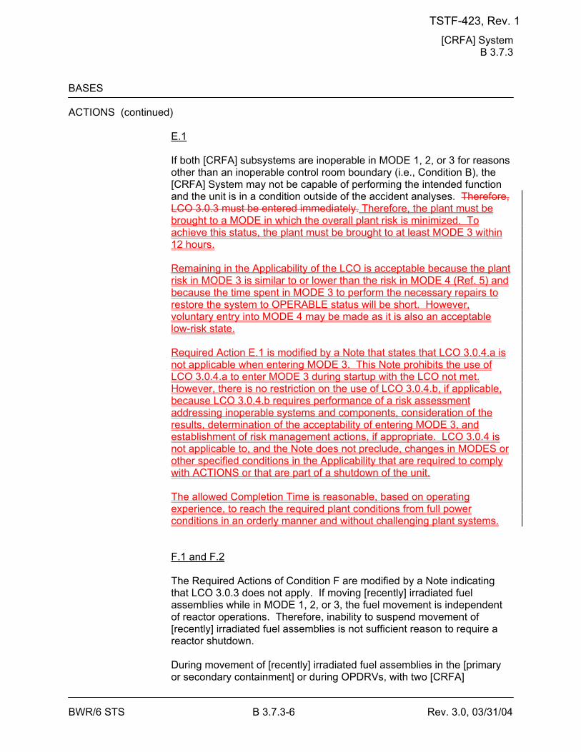
[CRFA] System B 3.7.3
BWR/6 STS B 3.7.3-6 Rev. 3.0, 03/31/04
BASES ACTIONS (continued)
E.1 If both [CRFA] subsystems are inoperable in MODE 1, 2, or 3 for reasons other than an inoperable control room boundary (i.e., Condition B), the [CRFA] System may not be capable of performing the intended function and the unit is in a condition outside of the accident analyses. Therefore, LCO 3.0.3 must be entered immediately. Therefore, the plant must be brought to a MODE in which the overall plant risk is minimized. To achieve this status, the plant must be brought to at least MODE 3 within 12 hours. Remaining in the Applicability of the LCO is acceptable because the plant risk in MODE 3 is similar to or lower than the risk in MODE 4 (Ref. 5) and because the time spent in MODE 3 to perform the necessary repairs to restore the system to OPERABLE status will be short. However, voluntary entry into MODE 4 may be made as it is also an acceptable low-risk state. Required Action E.1 is modified by a Note that states that LCO 3.0.4.a is not applicable when entering MODE 3. This Note prohibits the use of LCO 3.0.4.a to enter MODE 3 during startup with the LCO not met. However, there is no restriction on the use of LCO 3.0.4.b, if applicable, because LCO 3.0.4.b requires performance of a risk assessment addressing inoperable systems and components, consideration of the results, determination of the acceptability of entering MODE 3, and establishment of risk management actions, if appropriate. LCO 3.0.4 is not applicable to, and the Note does not preclude, changes in MODES or other specified conditions in the Applicability that are required to comply with ACTIONS or that are part of a shutdown of the unit. The allowed Completion Time is reasonable, based on operating experience, to reach the required plant conditions from full power conditions in an orderly manner and without challenging plant systems. F.1 and F.2 The Required Actions of Condition F are modified by a Note indicating that LCO 3.0.3 does not apply. If moving [recently] irradiated fuel assemblies while in MODE 1, 2, or 3, the fuel movement is independent of reactor operations. Therefore, inability to suspend movement of [recently] irradiated fuel assemblies is not sufficient reason to require a reactor shutdown. During movement of [recently] irradiated fuel assemblies in the [primary or secondary containment] or during OPDRVs, with two [CRFA]
TSTF-423, Rev. 1
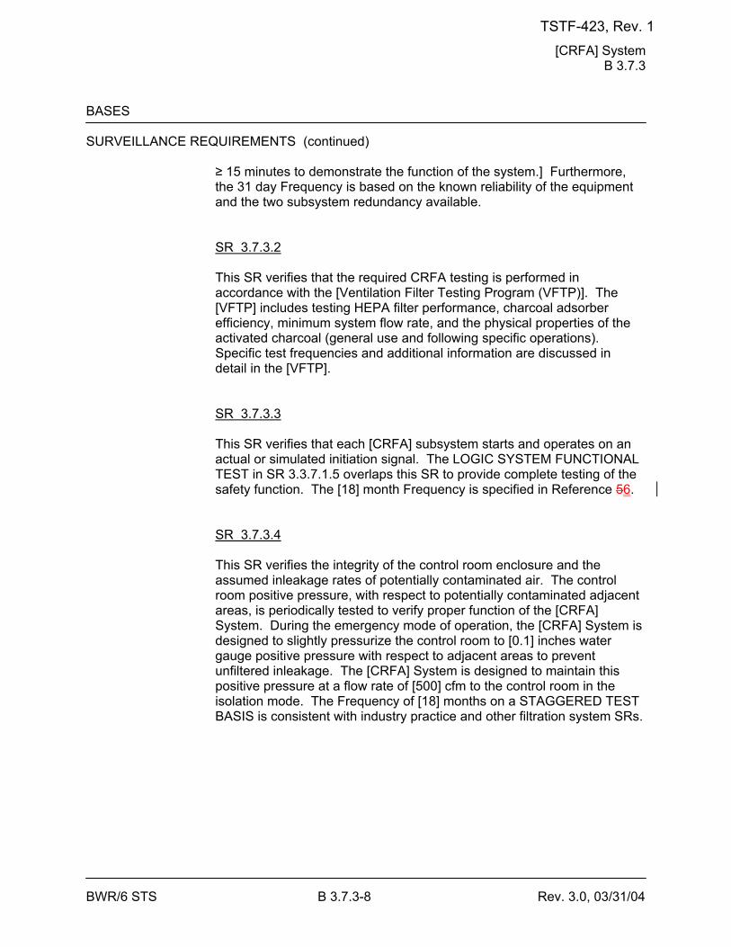
[CRFA] System B 3.7.3
BWR/6 STS B 3.7.3-8 Rev. 3.0, 03/31/04
BASES SURVEILLANCE REQUIREMENTS (continued)
≥ 15 minutes to demonstrate the function of the system.] Furthermore, the 31 day Frequency is based on the known reliability of the equipment and the two subsystem redundancy available. SR 3.7.3.2 This SR verifies that the required CRFA testing is performed in accordance with the [Ventilation Filter Testing Program (VFTP)]. The [VFTP] includes testing HEPA filter performance, charcoal adsorber efficiency, minimum system flow rate, and the physical properties of the activated charcoal (general use and following specific operations). Specific test frequencies and additional information are discussed in detail in the [VFTP]. SR 3.7.3.3 This SR verifies that each [CRFA] subsystem starts and operates on an actual or simulated initiation signal. The LOGIC SYSTEM FUNCTIONAL TEST in SR 3.3.7.1.5 overlaps this SR to provide complete testing of the safety function. The [18] month Frequency is specified in Reference 56. SR 3.7.3.4 This SR verifies the integrity of the control room enclosure and the assumed inleakage rates of potentially contaminated air. The control room positive pressure, with respect to potentially contaminated adjacent areas, is periodically tested to verify proper function of the [CRFA] System. During the emergency mode of operation, the [CRFA] System is designed to slightly pressurize the control room to [0.1] inches water gauge positive pressure with respect to adjacent areas to prevent unfiltered inleakage. The [CRFA] System is designed to maintain this positive pressure at a flow rate of [500] cfm to the control room in the isolation mode. The Frequency of [18] months on a STAGGERED TEST BASIS is consistent with industry practice and other filtration system SRs.
TSTF-423, Rev. 1
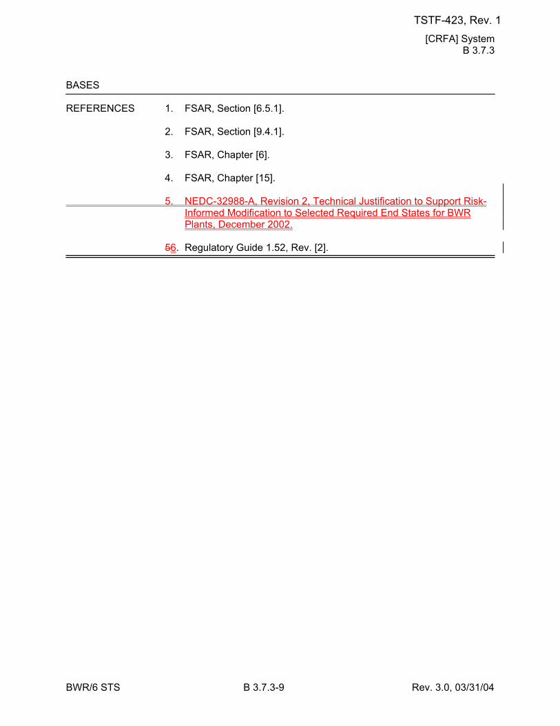
[CRFA] System B 3.7.3
BWR/6 STS B 3.7.3-9 Rev. 3.0, 03/31/04
BASES REFERENCES 1. FSAR, Section [6.5.1]. 2. FSAR, Section [9.4.1]. 3. FSAR, Chapter [6]. 4. FSAR, Chapter [15]. 5. NEDC-32988-A, Revision 2, Technical Justification to Support Risk-
Informed Modification to Selected Required End States for BWR Plants, December 2002.
56. Regulatory Guide 1.52, Rev. [2].
TSTF-423, Rev. 1
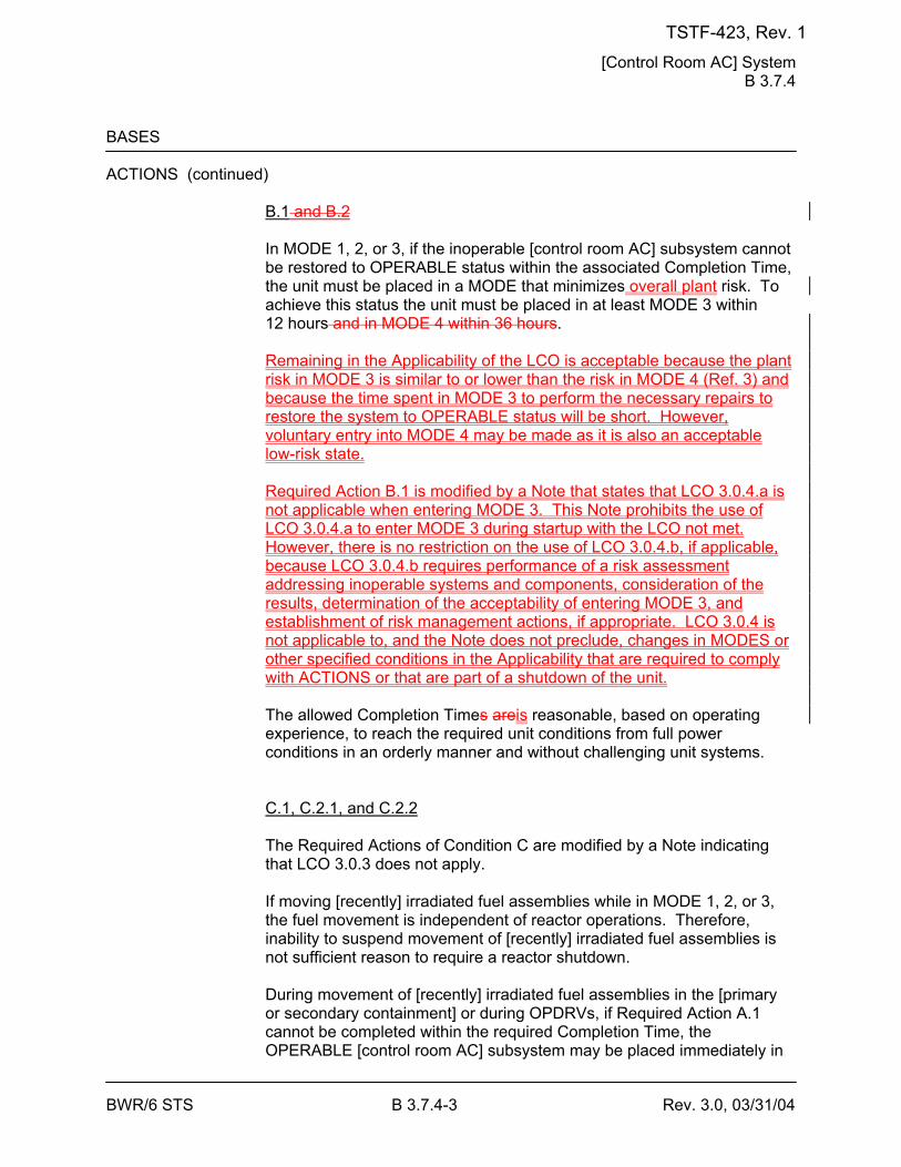
[Control Room AC] System B 3.7.4
BWR/6 STS B 3.7.4-3 Rev. 3.0, 03/31/04
BASES ACTIONS (continued)
B.1 and B.2 In MODE 1, 2, or 3, if the inoperable [control room AC] subsystem cannot be restored to OPERABLE status within the associated Completion Time, the unit must be placed in a MODE that minimizes overall plant risk. To achieve this status the unit must be placed in at least MODE 3 within 12 hours and in MODE 4 within 36 hours. Remaining in the Applicability of the LCO is acceptable because the plant risk in MODE 3 is similar to or lower than the risk in MODE 4 (Ref. 3) and because the time spent in MODE 3 to perform the necessary repairs to restore the system to OPERABLE status will be short. However, voluntary entry into MODE 4 may be made as it is also an acceptable low-risk state. Required Action B.1 is modified by a Note that states that LCO 3.0.4.a is not applicable when entering MODE 3. This Note prohibits the use of LCO 3.0.4.a to enter MODE 3 during startup with the LCO not met. However, there is no restriction on the use of LCO 3.0.4.b, if applicable, because LCO 3.0.4.b requires performance of a risk assessment addressing inoperable systems and components, consideration of the results, determination of the acceptability of entering MODE 3, and establishment of risk management actions, if appropriate. LCO 3.0.4 is not applicable to, and the Note does not preclude, changes in MODES or other specified conditions in the Applicability that are required to comply with ACTIONS or that are part of a shutdown of the unit. The allowed Completion Times areis reasonable, based on operating experience, to reach the required unit conditions from full power conditions in an orderly manner and without challenging unit systems. C.1, C.2.1, and C.2.2 The Required Actions of Condition C are modified by a Note indicating that LCO 3.0.3 does not apply. If moving [recently] irradiated fuel assemblies while in MODE 1, 2, or 3, the fuel movement is independent of reactor operations. Therefore, inability to suspend movement of [recently] irradiated fuel assemblies is not sufficient reason to require a reactor shutdown. During movement of [recently] irradiated fuel assemblies in the [primary or secondary containment] or during OPDRVs, if Required Action A.1 cannot be completed within the required Completion Time, the OPERABLE [control room AC] subsystem may be placed immediately in
TSTF-423, Rev. 1
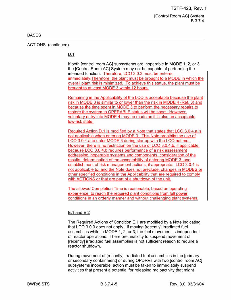
[Control Room AC] System B 3.7.4
BWR/6 STS B 3.7.4-5 Rev. 3.0, 03/31/04
BASES ACTIONS (continued)
D.1 If both [control room AC] subsystems are inoperable in MODE 1, 2, or 3, the [Control Room AC] System may not be capable of performing the intended function. Therefore, LCO 3.0.3 must be entered immediately.Therefore, the plant must be brought to a MODE in which the overall plant risk is minimized. To achieve this status, the plant must be brought to at least MODE 3 within 12 hours. Remaining in the Applicability of the LCO is acceptable because the plant risk in MODE 3 is similar to or lower than the risk in MODE 4 (Ref, 3) and because the time spent in MODE 3 to perform the necessary repairs to restore the system to OPERABLE status will be short. However, voluntary entry into MODE 4 may be made as it is also an acceptable low-risk state. Required Action D.1 is modified by a Note that states that LCO 3.0.4.a is not applicable when entering MODE 3. This Note prohibits the use of LCO 3.0.4.a to enter MODE 3 during startup with the LCO not met. However, there is no restriction on the use of LCO 3.0.4.b, if applicable, because LCO 3.0.4.b requires performance of a risk assessment addressing inoperable systems and components, consideration of the results, determination of the acceptability of entering MODE 3, and establishment of risk management actions, if appropriate. LCO 3.0.4 is not applicable to, and the Note does not preclude, changes in MODES or other specified conditions in the Applicability that are required to comply with ACTIONS or that are part of a shutdown of the unit. The allowed Completion Time is reasonable, based on operating experience, to reach the required plant conditions from full power conditions in an orderly manner and without challenging plant systems. E.1 and E.2 The Required Actions of Condition E.1 are modified by a Note indicating that LCO 3.0.3 does not apply. If moving [recently] irradiated fuel assemblies while in MODE 1, 2, or 3, the fuel movement is independent of reactor operations. Therefore, inability to suspend movement of [recently] irradiated fuel assemblies is not sufficient reason to require a reactor shutdown. During movement of [recently] irradiated fuel assemblies in the [primary or secondary containment] or during OPDRVs with two [control room AC] subsystems inoperable, action must be taken to immediately suspend activities that present a potential for releasing radioactivity that might
TSTF-423, Rev. 1
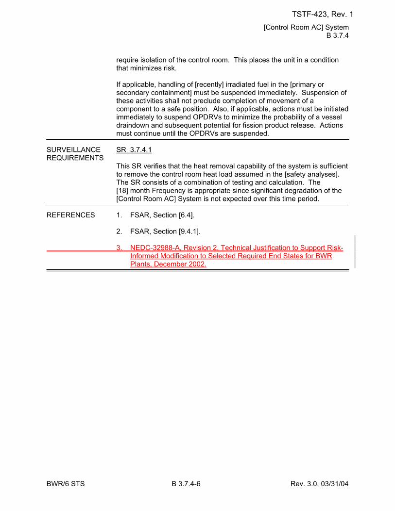
[Control Room AC] System B 3.7.4
BWR/6 STS B 3.7.4-6 Rev. 3.0, 03/31/04
require isolation of the control room. This places the unit in a condition that minimizes risk. If applicable, handling of [recently] irradiated fuel in the [primary or secondary containment] must be suspended immediately. Suspension of these activities shall not preclude completion of movement of a component to a safe position. Also, if applicable, actions must be initiated immediately to suspend OPDRVs to minimize the probability of a vessel draindown and subsequent potential for fission product release. Actions must continue until the OPDRVs are suspended.
SURVEILLANCE SR 3.7.4.1 REQUIREMENTS
This SR verifies that the heat removal capability of the system is sufficient to remove the control room heat load assumed in the [safety analyses]. The SR consists of a combination of testing and calculation. The [18] month Frequency is appropriate since significant degradation of the [Control Room AC] System is not expected over this time period.
REFERENCES 1. FSAR, Section [6.4]. 2. FSAR, Section [9.4.1]. 3. NEDC-32988-A, Revision 2, Technical Justification to Support Risk-
Informed Modification to Selected Required End States for BWR Plants, December 2002.
TSTF-423, Rev. 1
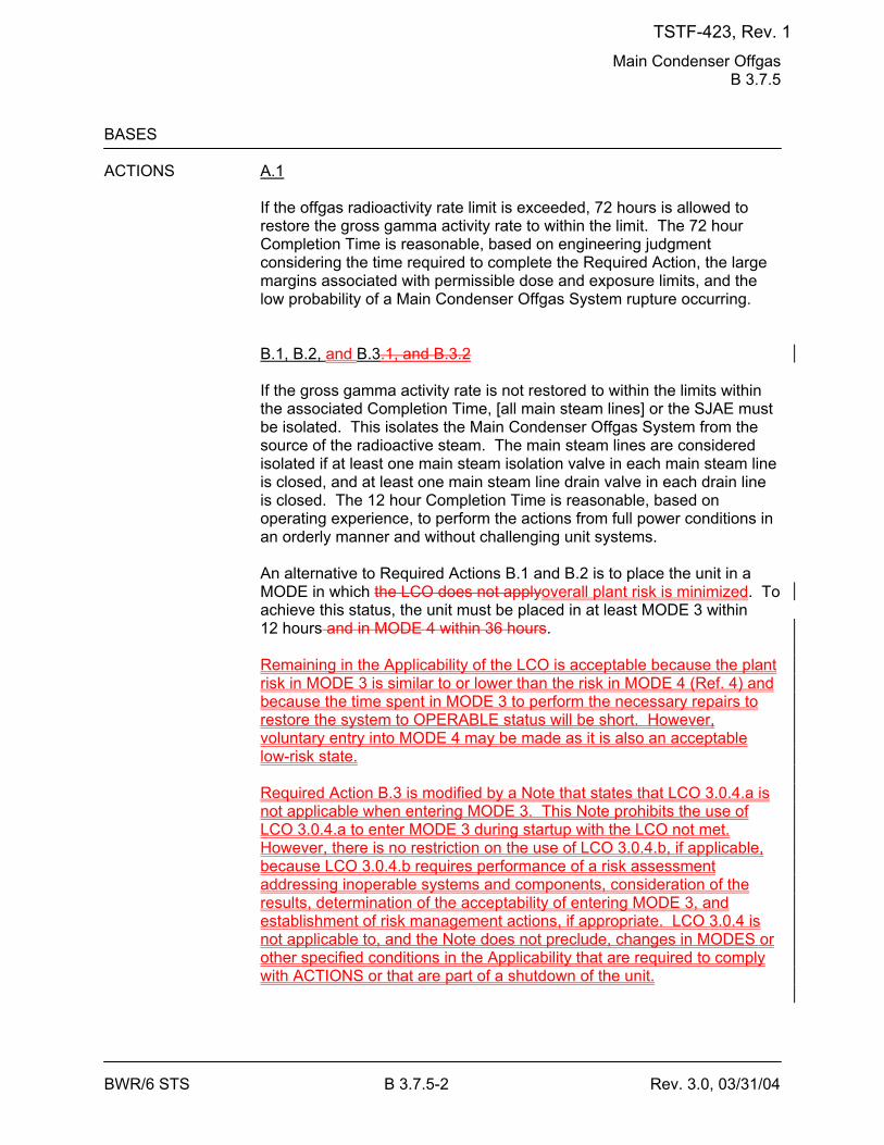
Main Condenser Offgas B 3.7.5
BWR/6 STS B 3.7.5-2 Rev. 3.0, 03/31/04
BASES ACTIONS A.1
If the offgas radioactivity rate limit is exceeded, 72 hours is allowed to restore the gross gamma activity rate to within the limit. The 72 hour Completion Time is reasonable, based on engineering judgment considering the time required to complete the Required Action, the large margins associated with permissible dose and exposure limits, and the low probability of a Main Condenser Offgas System rupture occurring. B.1, B.2, and B.3.1, and B.3.2 If the gross gamma activity rate is not restored to within the limits within the associated Completion Time, [all main steam lines] or the SJAE must be isolated. This isolates the Main Condenser Offgas System from the source of the radioactive steam. The main steam lines are considered isolated if at least one main steam isolation valve in each main steam line is closed, and at least one main steam line drain valve in each drain line is closed. The 12 hour Completion Time is reasonable, based on operating experience, to perform the actions from full power conditions in an orderly manner and without challenging unit systems. An alternative to Required Actions B.1 and B.2 is to place the unit in a MODE in which the LCO does not applyoverall plant risk is minimized. To achieve this status, the unit must be placed in at least MODE 3 within 12 hours and in MODE 4 within 36 hours. Remaining in the Applicability of the LCO is acceptable because the plant risk in MODE 3 is similar to or lower than the risk in MODE 4 (Ref. 4) and because the time spent in MODE 3 to perform the necessary repairs to restore the system to OPERABLE status will be short. However, voluntary entry into MODE 4 may be made as it is also an acceptable low-risk state. Required Action B.3 is modified by a Note that states that LCO 3.0.4.a is not applicable when entering MODE 3. This Note prohibits the use of LCO 3.0.4.a to enter MODE 3 during startup with the LCO not met. However, there is no restriction on the use of LCO 3.0.4.b, if applicable, because LCO 3.0.4.b requires performance of a risk assessment addressing inoperable systems and components, consideration of the results, determination of the acceptability of entering MODE 3, and establishment of risk management actions, if appropriate. LCO 3.0.4 is not applicable to, and the Note does not preclude, changes in MODES or other specified conditions in the Applicability that are required to comply with ACTIONS or that are part of a shutdown of the unit.
TSTF-423, Rev. 1

Main Condenser Offgas B 3.7.5
BWR/6 STS B 3.7.5-3 Rev. 3.0, 03/31/04
The allowed Completion Times areis reasonable, based on operating experience, to reach the required unit conditions from full power conditions in an orderly manner and without challenging unit systems.
SURVEILLANCE SR 3.7.5.1 REQUIREMENTS
This SR, on a 31 day Frequency, requires an isotopic analysis of an offgas sample to ensure that the required limits are satisfied. The noble gases to be sampled are Xe-133, Xe-135, Xe-138, Kr-85, Kr-87, and Kr-88. If the measured rate of radioactivity increases significantly (by ≥ 50% after correcting for expected increases due to changes in THERMAL POWER), an isotopic analysis is also performed within 4 hours after the increase is noted, to ensure that the increase is not indicative of a sustained increase in the radioactivity rate. The 31 day Frequency is adequate in view of other instrumentation that continuously monitor the offgas, and is acceptable based on operating experience. This SR is modified by a Note indicating that the SR is not required to be performed until 31 days after any [main steam line is not isolated] and the SJAE is in operation. Only in this condition can radioactive fission gases be in the Main Condenser Offgas System at significant rates.
TSTF-423, Rev. 1
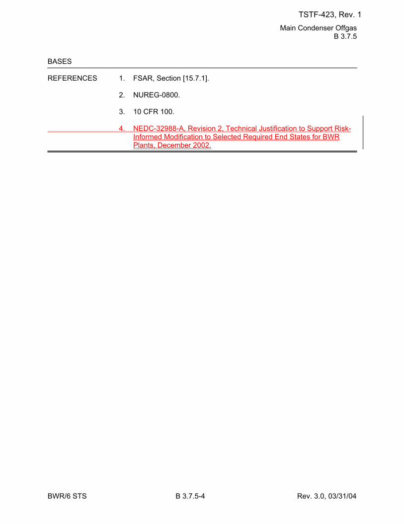
Main Condenser Offgas B 3.7.5
BWR/6 STS B 3.7.5-4 Rev. 3.0, 03/31/04
BASES REFERENCES 1. FSAR, Section [15.7.1]. 2. NUREG-0800. 3. 10 CFR 100. 4. NEDC-32988-A, Revision 2, Technical Justification to Support Risk-
Informed Modification to Selected Required End States for BWR Plants, December 2002.
TSTF-423, Rev. 1
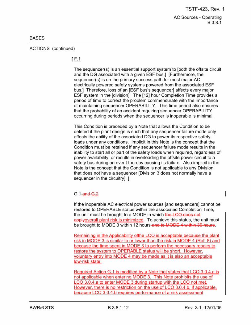
AC Sources - Operating B 3.8.1
BWR/6 STS B 3.8.1-12 Rev. 3.1, 12/01/05
BASES ACTIONS (continued)
[ F.1 The sequencer(s) is an essential support system to [both the offsite circuit and the DG associated with a given ESF bus.] [Furthermore, the sequencer(s) is on the primary success path for most major AC electrically powered safety systems powered from the associated ESF bus.] Therefore, loss of an [ESF bus's sequencer] affects every major ESF system in the [division]. The [12] hour Completion Time provides a period of time to correct the problem commensurate with the importance of maintaining sequencer OPERABILITY. This time period also ensures that the probability of an accident requiring sequencer OPERABILITY occurring during periods when the sequencer is inoperable is minimal. This Condition is preceded by a Note that allows the Condition to be deleted if the plant design is such that any sequencer failure mode only affects the ability of the associated DG to power its respective safety loads under any conditions. Implicit in this Note is the concept that the Condition must be retained if any sequencer failure mode results in the inability to start all or part of the safety loads when required, regardless of power availability, or results in overloading the offsite power circuit to a safety bus during an event thereby causing its failure. Also implicit in the Note is the concept that the Condition is not applicable to any Division that does not have a sequencer [Division 3 does not normally have a sequencer in the circuitry]. ] G.1 and G.2 If the inoperable AC electrical power sources [and sequencers] cannot be restored to OPERABLE status within the associated Completion Time, the unit must be brought to a MODE in which the LCO does not applyoverall plant risk is minimized. To achieve this status, the unit must be brought to MODE 3 within 12 hours and to MODE 4 within 36 hours. Remaining in the Applicability ofthe LCO is acceptable because the plant risk in MODE 3 is similar to or lower than the risk in MODE 4 (Ref. 8) and because the time spent in MODE 3 to perform the necessary repairs to restore the system to OPERABLE status will be short. However, voluntary entry into MODE 4 may be made as it is also an acceptable low-risk state. Required Action G.1 is modified by a Note that states that LCO 3.0.4.a is not applicable when entering MODE 3. This Note prohibits the use of LCO 3.0.4.a to enter MODE 3 during startup with the LCO not met. However, there is no restriction on the use of LCO 3.0.4.b, if applicable, because LCO 3.0.4.b requires performance of a risk assessment
TSTF-423, Rev. 1
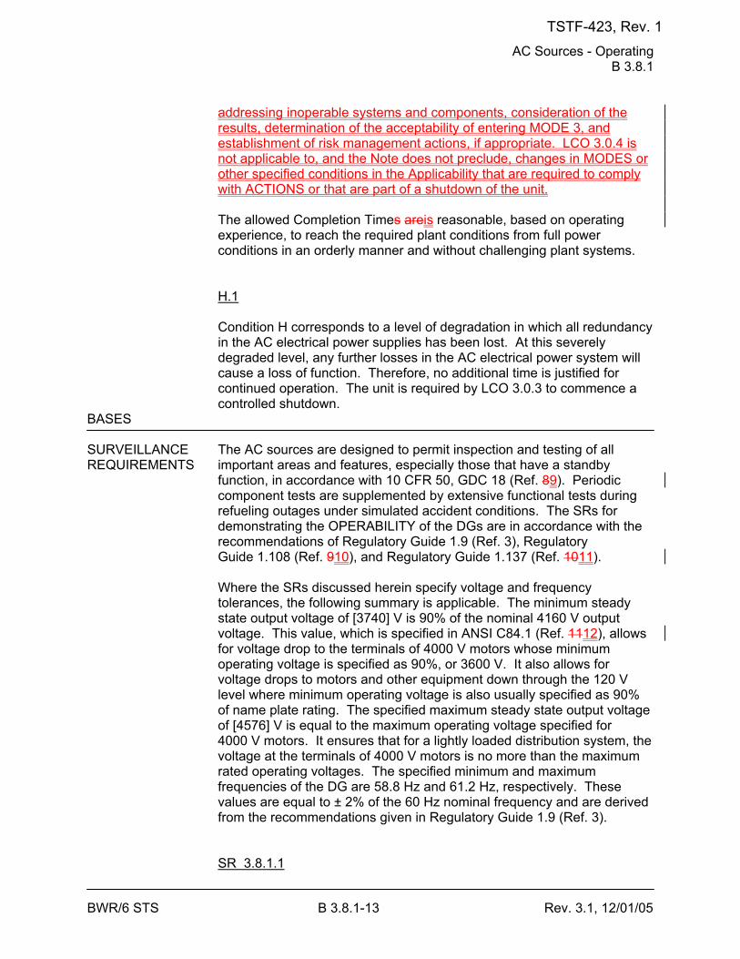
AC Sources - Operating B 3.8.1
BWR/6 STS B 3.8.1-13 Rev. 3.1, 12/01/05
addressing inoperable systems and components, consideration of the results, determination of the acceptability of entering MODE 3, and establishment of risk management actions, if appropriate. LCO 3.0.4 is not applicable to, and the Note does not preclude, changes in MODES or other specified conditions in the Applicability that are required to comply with ACTIONS or that are part of a shutdown of the unit. The allowed Completion Times areis reasonable, based on operating experience, to reach the required plant conditions from full power conditions in an orderly manner and without challenging plant systems. H.1 Condition H corresponds to a level of degradation in which all redundancy in the AC electrical power supplies has been lost. At this severely degraded level, any further losses in the AC electrical power system will cause a loss of function. Therefore, no additional time is justified for continued operation. The unit is required by LCO 3.0.3 to commence a controlled shutdown.
BASES SURVEILLANCE The AC sources are designed to permit inspection and testing of all REQUIREMENTS important areas and features, especially those that have a standby
function, in accordance with 10 CFR 50, GDC 18 (Ref. 89). Periodic component tests are supplemented by extensive functional tests during refueling outages under simulated accident conditions. The SRs for demonstrating the OPERABILITY of the DGs are in accordance with the recommendations of Regulatory Guide 1.9 (Ref. 3), Regulatory Guide 1.108 (Ref. 910), and Regulatory Guide 1.137 (Ref. 1011). Where the SRs discussed herein specify voltage and frequency tolerances, the following summary is applicable. The minimum steady state output voltage of [3740] V is 90% of the nominal 4160 V output voltage. This value, which is specified in ANSI C84.1 (Ref. 1112), allows for voltage drop to the terminals of 4000 V motors whose minimum operating voltage is specified as 90%, or 3600 V. It also allows for voltage drops to motors and other equipment down through the 120 V level where minimum operating voltage is also usually specified as 90% of name plate rating. The specified maximum steady state output voltage of [4576] V is equal to the maximum operating voltage specified for 4000 V motors. It ensures that for a lightly loaded distribution system, the voltage at the terminals of 4000 V motors is no more than the maximum rated operating voltages. The specified minimum and maximum frequencies of the DG are 58.8 Hz and 61.2 Hz, respectively. These values are equal to ± 2% of the 60 Hz nominal frequency and are derived from the recommendations given in Regulatory Guide 1.9 (Ref. 3). SR 3.8.1.1
TSTF-423, Rev. 1
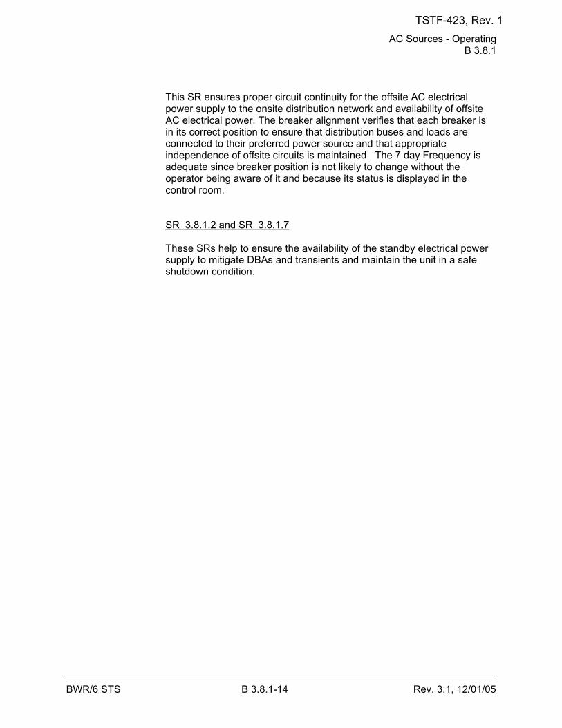
AC Sources - Operating B 3.8.1
BWR/6 STS B 3.8.1-14 Rev. 3.1, 12/01/05
This SR ensures proper circuit continuity for the offsite AC electrical power supply to the onsite distribution network and availability of offsite AC electrical power. The breaker alignment verifies that each breaker is in its correct position to ensure that distribution buses and loads are connected to their preferred power source and that appropriate independence of offsite circuits is maintained. The 7 day Frequency is adequate since breaker position is not likely to change without the operator being aware of it and because its status is displayed in the control room. SR 3.8.1.2 and SR 3.8.1.7 These SRs help to ensure the availability of the standby electrical power supply to mitigate DBAs and transients and maintain the unit in a safe shutdown condition.
TSTF-423, Rev. 1
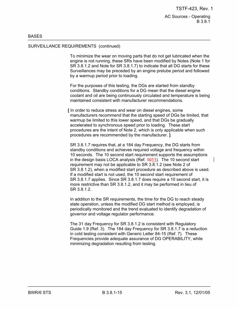
AC Sources - Operating B 3.8.1
BWR/6 STS B 3.8.1-15 Rev. 3.1, 12/01/05
BASES SURVEILLANCE REQUIREMENTS (continued)
To minimize the wear on moving parts that do not get lubricated when the engine is not running, these SRs have been modified by Notes (Note 1 for SR 3.8.1.2 and Note for SR 3.8.1.7) to indicate that all DG starts for these Surveillances may be preceded by an engine prelube period and followed by a warmup period prior to loading. For the purposes of this testing, the DGs are started from standby conditions. Standby conditions for a DG mean that the diesel engine coolant and oil are being continuously circulated and temperature is being maintained consistent with manufacturer recommendations.
[ In order to reduce stress and wear on diesel engines, some manufacturers recommend that the starting speed of DGs be limited, that warmup be limited to this lower speed, and that DGs be gradually accelerated to synchronous speed prior to loading. These start procedures are the intent of Note 2, which is only applicable when such procedures are recommended by the manufacturer. ] SR 3.8.1.7 requires that, at a 184 day Frequency, the DG starts from standby conditions and achieves required voltage and frequency within 10 seconds. The 10 second start requirement supports the assumptions in the design basis LOCA analysis (Ref. 1011). The 10 second start requirement may not be applicable to SR 3.8.1.2 (see Note 2 of SR 3.8.1.2), when a modified start procedure as described above is used. If a modified start is not used, the 10 second start requirement of SR 3.8.1.7 applies. Since SR 3.8.1.7 does require a 10 second start, it is more restrictive than SR 3.8.1.2, and it may be performed in lieu of SR 3.8.1.2. In addition to the SR requirements, the time for the DG to reach steady state operation, unless the modified DG start method is employed, is periodically monitored and the trend evaluated to identify degradation of governor and voltage regulator performance. The 31 day Frequency for SR 3.8.1.2 is consistent with Regulatory Guide 1.9 (Ref. 3). The 184 day Frequency for SR 3.8.1.7 is a reduction in cold testing consistent with Generic Letter 84-15 (Ref. 7). These Frequencies provide adequate assurance of DG OPERABILITY, while minimizing degradation resulting from testing.
TSTF-423, Rev. 1
AC Sources - Operating B 3.8.1
BWR/6 STS B 3.8.1-17 Rev. 3.1, 12/01/05
BASES SURVEILLANCE REQUIREMENTS (continued)
The 31 day Frequency is adequate to assure that a sufficient supply of fuel oil is available, since low level alarms are provided and facility operators would be aware of any large uses of fuel oil during this period. SR 3.8.1.5 Microbiological fouling is a major cause of fuel oil degradation. There are numerous bacteria that can grow in fuel oil and cause fouling, but all must have a water environment in order to survive. Removal of water from the fuel oil day [and engine mounted] tanks once every [31] days eliminates the necessary environment for bacterial survival. This is most effective means in controlling microbiological fouling. In addition, it eliminates the potential for water entrainment in the fuel oil during DG operation. Water may come from any of several sources, including condensation, ground water, rain water, contaminated fuel oil, and breakdown of the fuel oil by bacteria. Frequent checking for and removal of accumulated water minimizes fouling and provides data regarding the watertight integrity of the fuel oil system. The Surveillance Frequencies are established by Regulatory Guide 1.137 (Ref. 1011). This SR is for preventive maintenance. The presence of water does not necessarily represent a failure of this SR provided that accumulated water is removed during performance of this Surveillance. SR 3.8.1.6 This Surveillance demonstrates that each required fuel oil transfer pump operates and transfers fuel oil from its associated storage tank to its associated day tank. It is required to support the continuous operation of standby power sources. This Surveillance provides assurance that the fuel oil transfer pump is OPERABLE, the fuel oil piping system is intact, the fuel delivery piping is not obstructed, and the controls and control systems for automatic fuel transfer systems are OPERABLE.
[ The Frequency for this SR is variable, depending on individual system design, with up to a 92 day interval. The 92 day Frequency corresponds to the testing requirements for pumps as contained in the ASME Boiler and Pressure Vessel Code (Ref. 1213); however, the design of fuel transfer systems is such that pumps operate automatically or must be started manually in order to maintain an adequate volume of fuel oil in the day [and engine mounted] tanks during or following DG testing. In such a case, a 31 day Frequency is appropriate. Since proper operation of fuel transfer systems is an inherent part of DG OPERABILITY, the Frequency of this SR should be modified to reflect individual designs. ]
TSTF-423, Rev. 1
AC Sources - Operating B 3.8.1
BWR/6 STS B 3.8.1-19 Rev. 3.1, 12/01/05
BASES SURVEILLANCE REQUIREMENTS (continued)
SR 3.8.1.9 Each DG is provided with an engine overspeed trip to prevent damage to the engine. Recovery from the transient caused by the loss of a large load could cause diesel engine overspeed, which, if excessive, might result in a trip of the engine. This Surveillance demonstrates the DG load response characteristics and capability to reject the largest single load without exceeding predetermined voltage and frequency and while maintaining a specified margin to the overspeed trip. The load referenced for DG 11 is the 1200 kW low pressure core spray pump; for DG 12, the 550 kW residual heat removal (RHR) pump; and for DG 13 the 2180 kW HPCS pump. The Standby Service Water (SSW) pump values are not used as the largest load since the SSW supplies cooling to the associated DG. If this load were to trip, it would result in the loss of the DG. This Surveillance may be accomplished by: a. Tripping the DG output breaker with the DG carrying greater than or
equal to its associated single largest post-accident load while paralleled to offsite power, or while solely supplying the bus, or
b. Tripping its associated single largest post-accident load with the DG
solely supplying the bus. As required by IEEE-308 (Ref. 1314), the load rejection test is acceptable if the increase in diesel speed does not exceed 75% of the difference between synchronous speed and the overspeed trip setpoint, or 15% above synchronous speed, whichever is lower. For the Grand Gulf Nuclear Station these values are the same. The time, voltage, and frequency tolerances specified in this SR are derived from Regulatory Guide 1.9 (Ref. 3) recommendations for response during load sequence intervals. The 3 seconds specified is equal to 60% of the 5 second load sequence interval associated with sequencing of this largest load. The voltage and frequency specified are consistent with the design range of the equipment powered by the DG. SR 3.8.1.9.a corresponds to the maximum frequency excursion, while SR 3.8.1.9.b and SR 3.8.1.9.c are steady state voltage and frequency values to which the system must recover following load rejection. The [18 month] Frequency is consistent with the recommendation of Regulatory Guide 1.108 (Ref. 910).
TSTF-423, Rev. 1
AC Sources - Operating B 3.8.1
BWR/6 STS B 3.8.1-21 Rev. 3.1, 12/01/05
BASES SURVEILLANCE REQUIREMENTS (continued)
-----------------------------------REVIEWER’S NOTE----------------------------------- The above MODE restrictions may be deleted if it can be demonstrated to the staff, on a plant specific basis, that performing the SR with the reactor in any of the restricted MODES can satisfy the following criteria, as applicable: a. Performance of the SR will not render any safety system or
component inoperable, b. Performance of the SR will not cause perturbations to any of the
electrical distribution systems that could result in a challenge to steady state operation or to plant safety systems, and
c. Performance of the SR, or failure of the SR, will not cause, or result
in, an AOO with attendant challenge to plant safety systems. -------------------------------------------------------------------------------------------------- SR 3.8.1.10
This Surveillance demonstrates the DG capability to reject a full load without overspeed tripping or exceeding the predetermined voltage limits. The DG full load rejection may occur because of a system fault or inadvertent breaker tripping. This Surveillance ensures proper engine generator load response under the simulated test conditions. This test simulates the loss of the total connected load that the DG experiences following a full load rejection and verifies that the DG does not trip upon loss of the load. These acceptance criteria provide DG damage protection. While the DG is not expected to experience this transient during an event, and continues to be available, this response ensures that the DG is not degraded for future application, including reconnection to the bus if the trip initiator can be corrected or isolated. In order to ensure that the DG is tested under load conditions that are as close to design basis conditions as possible, testing must be performed using a power factor ≤ [0.9]. This power factor is chosen to be representative of the actual design basis inductive loading that the DG would experience. The [18 month] Frequency is consistent with the recommendation of Regulatory Guide 1.108 (Ref. 910) and is intended to be consistent with expected fuel cycle lengths.
TSTF-423, Rev. 1
AC Sources - Operating B 3.8.1
BWR/6 STS B 3.8.1-23 Rev. 3.1, 12/01/05
BASES SURVEILLANCE REQUIREMENTS (continued)
power factor other than ≤ [0.9]. These conditions occur when grid voltage is high, and the additional field excitation needed to get the power factor to ≤ [0.9] results in voltages on the emergency busses that are too high. Under these conditions, the power factor should be maintained as close as practicable to [0.9] while still maintaining acceptable voltage limits on the emergency busses. In other circumstances, the grid voltage may be such that the DG excitation levels needed to obtain a power factor of [0.9] may not cause unacceptable voltages on the emergency busses, but the excitation levels are in excess of those recommended for the DG. In such cases, the power factor shall be maintained as close to practicable to [0.9] without exceeding the DG excitation limits. SR 3.8.1.11 As required by Regulatory Guide 1.108 (Ref. 910), paragraph 2.a.(1), this Surveillance demonstrates the as designed operation of the standby power sources during loss of the offsite source. This test verifies all actions encountered from the loss of offsite power, including shedding of the nonessential loads and energization of the emergency buses and respective loads from the DG. It further demonstrates the capability of the DG to automatically achieve the required voltage and frequency within the specified time. The DG auto-start time of 10 seconds is derived from requirements of the accident analysis to respond to a design basis large break LOCA. The Surveillance should be continued for a minimum of 5 minutes in order to demonstrate that all starting transients have decayed and stability has been achieved. The requirement to verify the connection and power supply of permanent and auto-connected loads is intended to satisfactorily show the relationship of these loads to the DG loading logic. In certain circumstances, many of these loads cannot actually be connected or loaded without undue hardship or potential for undesired operation. For instance, ECCS injection valves are not desired to be stroked open, systems are not capable of being operated at full flow, or RHR systems performing a decay heat removal function are not desired to be realigned to the ECCS mode of operation. In lieu of actual demonstration of the connection and loading of these loads, testing that adequately shows the capability of the DG system to perform these functions is acceptable. This testing may include any series of sequential, overlapping, or total steps so that the entire connection and loading sequence is verified.
TSTF-423, Rev. 1
AC Sources - Operating B 3.8.1
BWR/6 STS B 3.8.1-24 Rev. 3.1, 12/01/05
BASES SURVEILLANCE REQUIREMENTS (continued)
The Frequency of [18 months] is consistent with the recommendations of Regulatory Guide 1.108 (Ref. 910), paragraph 2.a.(1), takes into consideration unit conditions required to perform the Surveillance, and is intended to be consistent with expected fuel cycle lengths. This SR is modified by two Notes. The reason for Note 1 is to minimize wear and tear on the DGs during testing. For the purpose of this testing, the DGs must be started from standby conditions, that is, with the engine coolant and oil being continuously circulated and temperature maintained consistent with manufacturer recommendations for [Division 1 and 2] DGs. [For the [Division 3] DG, standby conditions mean that the lube oil is heated and continuously circulated through a portion of the system as recommended by the vendor. Engine jacket water is heated by the lubricating oil and circulates through the system by natural circulation.] The reason for Note 2 is that performing the Surveillance would remove a required offsite circuit from service, perturb the electrical distribution system, and challenge plant safety systems. This restriction from normally performing the Surveillance in MODE 1 or 2 is further amplified to allow portions of the Surveillance to be performed for the purpose of reestablishing OPERABILITY (e.g., post work testing following corrective maintenance, corrective modification, deficient or incomplete surveillance testing, and other unanticipated OPERABILITY concerns) provided an assessment determines plant safety is maintained or enhanced. This assessment shall, as a minimum, consider the potential outcomes and transients associated with a failed partial Surveillance, a successful partial Surveillance, and a perturbation of the offsite or onsite system when they are tied together or operated independently for the partial Surveillance; as well as the operator procedures available to cope with these outcomes. These shall be measured against the avoided risk of a plant shutdown and startup to determine that plant safety is maintained or enhanced when portions of the Surveillance are performed in MODE 1 or 2. Risk insights or deterministic methods may be used for the assessment. Credit may be taken for unplanned events that satisfy this SR.
[ SR 3.8.1.12 This Surveillance demonstrates that the DG automatically starts and achieves the required voltage and frequency within the specified time ([10] seconds) from the design basis actuation signal (LOCA signal) and operates for ≥ [5] minutes. The [5] minute period provides sufficient time to demonstrate stability. SR 3.8.1.12.d and SR 3.8.1.12.e ensure that permanently connected loads and emergency loads are energized from the offsite electrical power system on an ECCS signal without loss of offsite power.
TSTF-423, Rev. 1
AC Sources - Operating B 3.8.1
BWR/6 STS B 3.8.1-27 Rev. 3.1, 12/01/05
BASES SURVEILLANCE REQUIREMENTS (continued)
Surveillance, and a perturbation of the offsite or onsite system when they are tied together or operated independently for the Surveillance; as well as the operator procedures available to cope with these outcomes. These shall be measured against the avoided risk of a plant shutdown and startup to determine that plant safety is maintained or enhanced when the Surveillance is performed in MODE 1 or 2. Risk insights or deterministic methods may be used for this assessment. Credit may be taken for unplanned events that satisfy this SR. -----------------------------------REVIEWER’S NOTE----------------------------------- The above MODE restrictions may be deleted if it can be demonstrated to the staff, on a plant specific basis, that performing the SR with the reactor in any of the restricted MODES can satisfy the following criteria, as applicable: a. Performance of the SR will not render any safety system or
component inoperable, b. Performance of the SR will not cause perturbations to any of the
electrical distribution systems that could result in a challenge to steady state operation or to plant safety systems, and
c. Performance of the SR, or failure of the SR, will not cause, or result
in, an AOO with attendant challenge to plant safety systems. -------------------------------------------------------------------------------------------------- SR 3.8.1.14 Regulatory Guide 1.108 (Ref. 910), paragraph 2.a.(3), requires demonstration once per 18 months that the DGs can start and run continuously at full load capability for an interval of not less than 24 hours - 22 hours of which is at a load equivalent to the continuous rating of the DG, and 2 hours of which is at a load equivalent to 110% of the continuous duty rating of the DG. The DG starts for this Surveillance can be performed either from standby or hot conditions. The provisions for prelube and warmup, discussed in SR 3.8.1.2, and for gradual loading, discussed in SR 3.8.1.3, are applicable to this SR. In order to ensure that the DG is tested under load conditions that are as close to design conditions as possible, testing must be performed using a power factor ≤ [0.9]. This power factor is chosen to be representative of the actual design basis inductive loading that the DG could experience.
TSTF-423, Rev. 1
AC Sources - Operating B 3.8.1
BWR/6 STS B 3.8.1-28 Rev. 3.1, 12/01/05
BASES SURVEILLANCE REQUIREMENTS (continued)
The [18 month] Frequency is consistent with the recommendations of Regulatory Guide 1.108 (Ref. 910), paragraph 2.a.(3); takes into consideration plant conditions required to perform the Surveillance; and is intended to be consistent with expected fuel cycle lengths. This Surveillance is modified by three Notes. Note 1 states that momentary transients due to changing bus loads do not invalidate this test. The load band is provided to avoid routine overloading of the DG. Routine overloading may result in more frequent teardown inspections in accordance with vendor recommendations in order to maintain DG OPERABILITY. Similarly, momentary power factor transients above the limit do not invalidate the test. The reason for Note 2 is that during operation with the reactor critical, performance of this SR could cause perturbations to the electrical distribution systems that would challenge continued steady state operation and, as a result, plant safety systems. This restriction from normally performing the Surveillance in MODE 1 or 2 is further amplified to allow the Surveillance to be performed for the purpose of reestablishing OPERABILITY (e.g. post work testing following corrective maintenance, corrective modification, deficient or incomplete surveillance testing, and other unanticipated OPERABILITY concerns) provided an assessment determines plant safety is maintained or enhanced. This assessment shall, as a minimum, consider the potential outcomes and transients associated with a failed Surveillance, a successful Surveillance, and a perturbation of the offsite or onsite system when they are tied together or operated independently for the Surveillance; as well as the operator procedures available to cope with these outcomes. These shall be measured against the avoided risk of a plant shutdown and startup to determine that plant safety is maintained or enhanced when the Surveillance is performed in MODE 1 or 2. Risk insights or deterministic methods may be used for this assessment. Credit may be taken for unplanned events that satisfy this SR. Note 3 ensures that the DG is tested under load conditions that are as close to design basis conditions as possible. When synchronized with offsite power, testing should be performed at a power factor of ≤ [0.9]. This power factor is representative of the actual inductive loading a DG would see under design basis accident conditions. Under certain conditions, however, Note 3 allows the surveillance to be conducted at a power factor other than ≤ [0.9]. These conditions occur when grid voltage is high, and the additional field excitation needed to get the power factor to ≤ [0.9] results in voltages on the emergency busses that are too high. Under these conditions, the power factor should be maintained as close as practicable to [0.9] while still maintaining acceptable voltage limits on the emergency busses. In other circumstances, the grid voltage may be such that the DG excitation levels needed to obtain a power factor of [0.9] may not cause unacceptable voltages on the emergency busses, but the excitation levels are in excess of those recommended for the DG. In such
TSTF-423, Rev. 1
AC Sources - Operating B 3.8.1
BWR/6 STS B 3.8.1-29 Rev. 3.1, 12/01/05
BASES SURVEILLANCE REQUIREMENTS (continued)
cases, the power factor shall be maintained as close as practicable to [0.9] without exceeding the DG excitation limits. SR 3.8.1.15 This Surveillance demonstrates that the diesel engine can restart from a hot condition, such as subsequent to shutdown from normal Surveillances, and achieve the required voltage and frequency within 10 seconds. The 10 second time is derived from the requirements of the accident analysis to respond to a design basis large break LOCA. The [18 month] Frequency is consistent with the recommendations of Regulatory Guide 1.108 (Ref. 910), paragraph 2.a.(5). This SR has been modified by two Notes. Note 1 ensures that the test is performed with the diesel sufficiently hot. The requirement that the diesel has operated for at least 2 hours at full load conditions prior to performance of this Surveillance is based on manufacturer recommendations for achieving hot conditions. The load band is provided to avoid routine overloading of the DG. Routine overloads may result in more frequent teardown inspections in accordance with vendor recommendations in order to maintain DG OPERABILITY. Momentary transients due to changing bus loads do not invalidate this test. Note 2 allows all DG starts to be preceded by an engine prelube period to minimize wear and tear on the diesel during testing. SR 3.8.1.16 As required by Regulatory Guide 1.108 (Ref. 910), paragraph 2.a.(6), this Surveillance ensures that the manual synchronization and automatic load transfer from the DG to the offsite source can be made and that the DG can be returned to ready-to-load status when offsite power is restored. It also ensures that the auto-start logic is reset to allow the DG to reload if a subsequent loss of offsite power occurs. The DG is considered to be in ready-to-load status when the DG is at rated speed and voltage, the output breaker is open and can receive an auto-close signal on bus undervoltage, and the load sequence timers are reset. The Frequency of [18 months] is consistent with the recommendations of Regulatory Guide 1.108 (Ref. 910), paragraph 2.1.(6), and takes into consideration plant conditions required to perform the Surveillance.
TSTF-423, Rev. 1
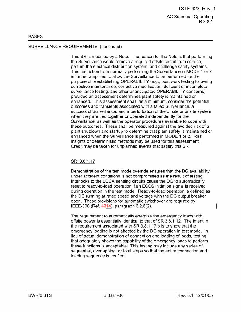
AC Sources - Operating B 3.8.1
BWR/6 STS B 3.8.1-30 Rev. 3.1, 12/01/05
BASES SURVEILLANCE REQUIREMENTS (continued)
This SR is modified by a Note. The reason for the Note is that performing the Surveillance would remove a required offsite circuit from service, perturb the electrical distribution system, and challenge safety systems. This restriction from normally performing the Surveillance in MODE 1 or 2 is further amplified to allow the Surveillance to be performed for the purpose of reestablishing OPERABILITY (e.g., post work testing following corrective maintenance, corrective modification, deficient or incomplete surveillance testing, and other unanticipated OPERABILITY concerns) provided an assessment determines plant safety is maintained or enhanced. This assessment shall, as a minimum, consider the potential outcomes and transients associated with a failed Surveillance, a successful Surveillance, and a perturbation of the offsite or onsite system when they are tied together or operated independently for the Surveillance; as well as the operator procedures available to cope with these outcomes. These shall be measured against the avoided risk of a plant shutdown and startup to determine that plant safety is maintained or enhanced when the Surveillance is performed in MODE 1 or 2. Risk insights or deterministic methods may be used for this assessment. Credit may be taken for unplanned events that satisfy this SR. SR 3.8.1.17 Demonstration of the test mode override ensures that the DG availability under accident conditions is not compromised as the result of testing. Interlocks to the LOCA sensing circuits cause the DG to automatically reset to ready-to-load operation if an ECCS initiation signal is received during operation in the test mode. Ready-to-load operation is defined as the DG running at rated speed and voltage with the DG output breaker open. These provisions for automatic switchover are required by IEEE-308 (Ref. 1314), paragraph 6.2.6(2). The requirement to automatically energize the emergency loads with offsite power is essentially identical to that of SR 3.8.1.12. The intent in the requirement associated with SR 3.8.1.17.b is to show that the emergency loading is not affected by the DG operation in test mode. In lieu of actual demonstration of connection and loading of loads, testing that adequately shows the capability of the emergency loads to perform these functions is acceptable. This testing may include any series of sequential, overlapping, or total steps so that the entire connection and loading sequence is verified.
TSTF-423, Rev. 1
AC Sources - Operating B 3.8.1
BWR/6 STS B 3.8.1-31 Rev. 3.1, 12/01/05
BASES SURVEILLANCE REQUIREMENTS (continued)
The [18 month] Frequency is consistent with the recommendations of Regulatory Guide 1.108 (Ref. 910), paragraph 2.a.(8); takes into consideration plant conditions required to perform the Surveillance; and is intended to be consistent with expected fuel cycle lengths. This SR has been modified by a Note. The reason for the Note is that performing the Surveillance would remove a required offsite circuit from service, perturb the electrical distribution system, and challenge safety systems. This restriction from normally performing the Surveillance in MODE 1 or 2 is further amplified to allow portions of the Surveillance to be performed for the purpose of reestablishing OPERABILITY (e.g., post work testing following corrective maintenance, corrective modification, deficient or incomplete surveillance testing, and other unanticipated OPERABILITY concerns) provided an assessment determines plant safety is maintained or enhanced. This assessment shall, as a minimum, consider the potential outcomes and transients associated with a failed partial Surveillance, a successful partial Surveillance, and a perturbation of the offsite or onsite system when they are tied together or operated independently for the partial Surveillance; as well as the operator procedures available to cope with these outcomes. These shall be measured against the avoided risk of a plant shutdown and startup to determine that plant safety is maintained or enhanced when portions of the Surveillance are performed in MODE 1 or 2. Risk insights or deterministic methods may be used for the assessment. Credit may be taken for unplanned events that satisfy this SR. SR 3.8.1.18 Under accident conditions [and loss of offsite power] loads are sequentially connected to the bus by the load sequencing panel. The sequencing logic controls the permissive and starting signals to motor breakers to prevent overloading of the DGs due to high motor starting currents. The [10]% load sequence time interval tolerance ensures that sufficient time exists for the DG to restore frequency and voltage prior to applying the next load and that safety analysis assumptions regarding ESF equipment time delays are not violated. Reference 2 provides a summary of the automatic loading of ESF buses. The Frequency of [18 months] is consistent with the recommendations of Regulatory Guide 1.108 (Ref. 910), paragraph 2.a.(2); takes into consideration plant conditions required to perform the Surveillance; and is intended to be consistent with expected fuel cycle lengths.
TSTF-423, Rev. 1
AC Sources - Operating B 3.8.1
BWR/6 STS B 3.8.1-34 Rev. 3.1, 12/01/05
BASES SURVEILLANCE REQUIREMENTS (continued)
SR 3.8.1.20 This Surveillance demonstrates that the DG starting independence has not been compromised. Also, this Surveillance demonstrates that each engine can achieve proper speed within the specified time when the DGs are started simultaneously. The 10 year Frequency is consistent with the recommendations of Regulatory Guide 1.108 (Ref. 910). This SR is modified by a Note. The reason for the Note is to minimize wear on the DG during testing. For the purpose of this testing, the DGs must be started from standby conditions, that is, with the engine coolant and oil continuously circulated and temperature maintained consistent with manufacturer recommendations.
REFERENCES 1. 10 CFR 50, Appendix A, GDC 17. 2. FSAR, Chapter [8]. 3. Regulatory Guide 1.9. 4. FSAR, Chapter [6]. 5. FSAR, Chapter [15]. 6. Regulatory Guide 1.93. 7. Generic Letter 84-15, July 2, 1984. 8. NEDC-32988-A, Revision 2, Technical Justification to Support Risk-
Informed Modification to Selected Required End States for BWR Plants, December 2002.
89. 10 CFR 50, Appendix A, GDC 18. 910. Regulatory Guide 1.108. 1011. Regulatory Guide 1.137. 1112. ANSI C84.1, 1982. 1213. ASME Code for Operation and Maintenance of Nuclear Power
Plants. 1314. IEEE Standard 308.
TSTF-423, Rev. 1
DC Sources - Operating B 3.8.4
BWR/6 STS B 3.8.4-7 Rev. 3.0, 03/31/04
BASES ACTIONS (continued)
C.1 Condition C represents one division with a loss of ability to completely respond to an event, and a potential loss of ability to remain energized during normal operation. It is, therefore, imperative that the operator's attention focus on stabilizing the unit, minimizing the potential for complete loss of DC power to the affected division. The 2 hour limit is consistent with the allowed time for an inoperable DC distribution system division. If one of the required [Division 1 or 2] DC electrical power subsystems is inoperable for reasons other than Condition A or B (e.g., inoperable battery charger and associated inoperable battery), the remaining DC electrical power subsystems have the capacity to support a safe shutdown and to mitigate an accident condition. Since a subsequent worst case single failure could, however, result in the loss of minimum necessary DC electrical subsystems, continued power operation should not exceed 2 hours. The 2 hour Completion Time is based on Regulatory Guide 1.93 (Ref. 7) and reflects a reasonable time to assess unit status as a function of the inoperable DC electrical power subsystem and, if the DC electrical power subsystem is not restored to OPERABLE status, to prepare to effect an orderly and safe unit shutdown. D.1 If a Division 1 or 2 DC electrical power subsystem is inoperable and not restored within the provided Completion Time, the plant must be brought to a condition in which overall plant risk is minimized. To achieve this status, the plant must be brought to at least MODE 3 within 12 hours. Remaining in the Applicability of the LCO is acceptable because the plant risk in MODE 3 is similar to or lower than the risk in MODE 4 (Ref. 8) and because the time spent in MODE 3 to perform the necessary repairs to restore the system to OPERABLE status will be short. However, voluntary entry into MODE 4 may be made as it is also an acceptable low-risk state. Required Action D.1 is modified by a Note that states that LCO 3.0.4.a is not applicable when entering MODE 3. This Note prohibits the use of LCO 3.0.4.a to enter MODE 3 during startup with the LCO not met. However, there is no restriction on the use of LCO 3.0.4.b, if applicable, because LCO 3.0.4.b requires performance of a risk assessment addressing inoperable systems and components, consideration of the results, determination of the acceptability of entering MODE 3, and establishment of risk management actions, if appropriate. LCO 3.0.4 is
TSTF-423, Rev. 1
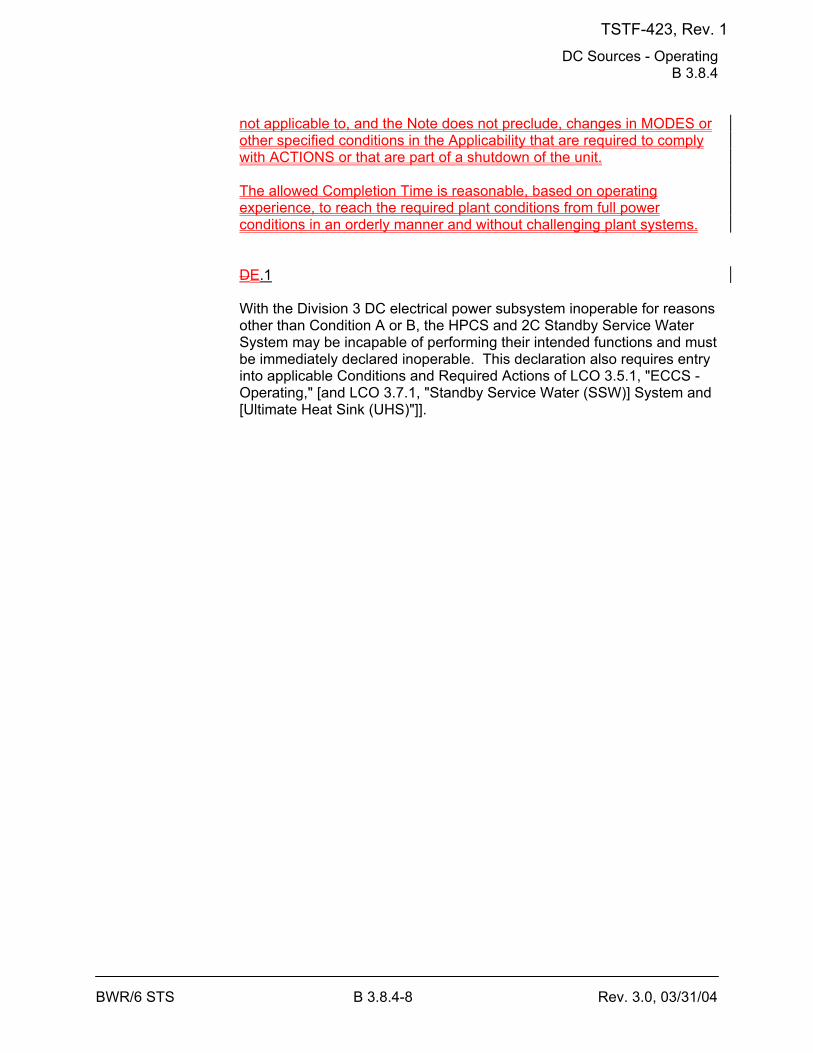
DC Sources - Operating B 3.8.4
BWR/6 STS B 3.8.4-8 Rev. 3.0, 03/31/04
not applicable to, and the Note does not preclude, changes in MODES or other specified conditions in the Applicability that are required to comply with ACTIONS or that are part of a shutdown of the unit. The allowed Completion Time is reasonable, based on operating experience, to reach the required plant conditions from full power conditions in an orderly manner and without challenging plant systems. DE.1 With the Division 3 DC electrical power subsystem inoperable for reasons other than Condition A or B, the HPCS and 2C Standby Service Water System may be incapable of performing their intended functions and must be immediately declared inoperable. This declaration also requires entry into applicable Conditions and Required Actions of LCO 3.5.1, "ECCS - Operating," [and LCO 3.7.1, "Standby Service Water (SSW)] System and [Ultimate Heat Sink (UHS)"]].
TSTF-423, Rev. 1
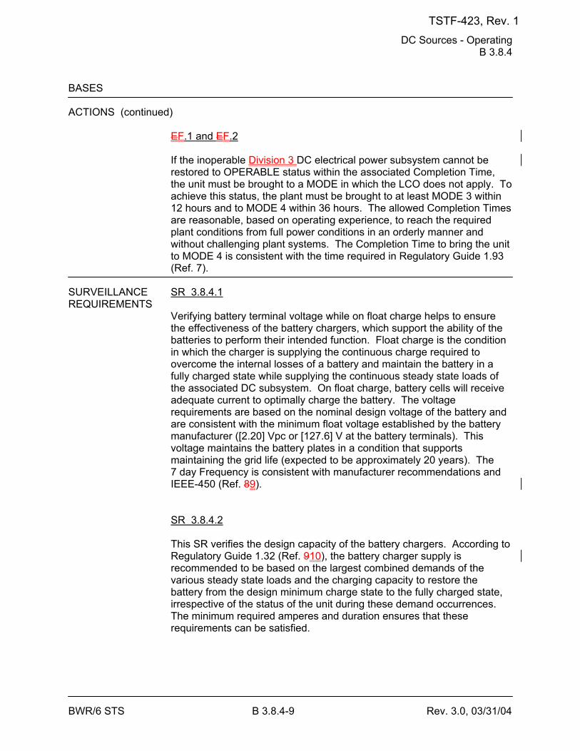
DC Sources - Operating B 3.8.4
BWR/6 STS B 3.8.4-9 Rev. 3.0, 03/31/04
BASES ACTIONS (continued)
EF.1 and EF.2 If the inoperable Division 3 DC electrical power subsystem cannot be restored to OPERABLE status within the associated Completion Time, the unit must be brought to a MODE in which the LCO does not apply. To achieve this status, the plant must be brought to at least MODE 3 within 12 hours and to MODE 4 within 36 hours. The allowed Completion Times are reasonable, based on operating experience, to reach the required plant conditions from full power conditions in an orderly manner and without challenging plant systems. The Completion Time to bring the unit to MODE 4 is consistent with the time required in Regulatory Guide 1.93 (Ref. 7).
SURVEILLANCE SR 3.8.4.1 REQUIREMENTS
Verifying battery terminal voltage while on float charge helps to ensure the effectiveness of the battery chargers, which support the ability of the batteries to perform their intended function. Float charge is the condition in which the charger is supplying the continuous charge required to overcome the internal losses of a battery and maintain the battery in a fully charged state while supplying the continuous steady state loads of the associated DC subsystem. On float charge, battery cells will receive adequate current to optimally charge the battery. The voltage requirements are based on the nominal design voltage of the battery and are consistent with the minimum float voltage established by the battery manufacturer ([2.20] Vpc or [127.6] V at the battery terminals). This voltage maintains the battery plates in a condition that supports maintaining the grid life (expected to be approximately 20 years). The 7 day Frequency is consistent with manufacturer recommendations and IEEE-450 (Ref. 89). SR 3.8.4.2 This SR verifies the design capacity of the battery chargers. According to Regulatory Guide 1.32 (Ref. 910), the battery charger supply is recommended to be based on the largest combined demands of the various steady state loads and the charging capacity to restore the battery from the design minimum charge state to the fully charged state, irrespective of the status of the unit during these demand occurrences. The minimum required amperes and duration ensures that these requirements can be satisfied.
TSTF-423, Rev. 1
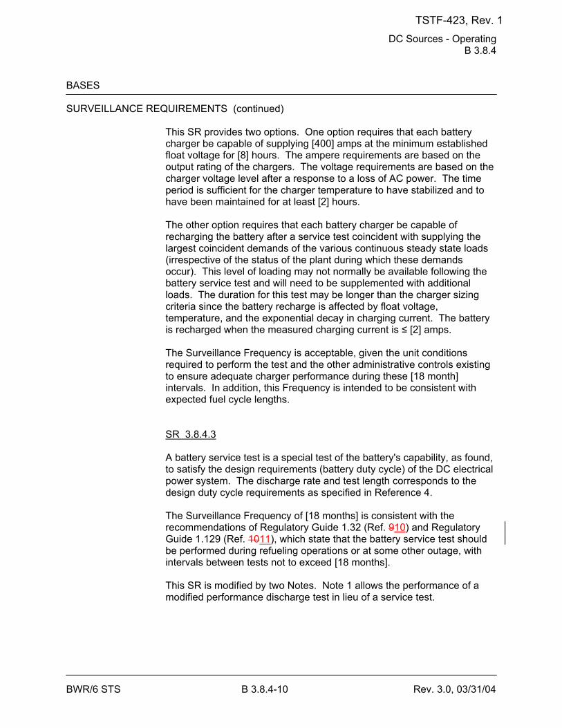
DC Sources - Operating B 3.8.4
BWR/6 STS B 3.8.4-10 Rev. 3.0, 03/31/04
BASES SURVEILLANCE REQUIREMENTS (continued)
This SR provides two options. One option requires that each battery charger be capable of supplying [400] amps at the minimum established float voltage for [8] hours. The ampere requirements are based on the output rating of the chargers. The voltage requirements are based on the charger voltage level after a response to a loss of AC power. The time period is sufficient for the charger temperature to have stabilized and to have been maintained for at least [2] hours. The other option requires that each battery charger be capable of recharging the battery after a service test coincident with supplying the largest coincident demands of the various continuous steady state loads (irrespective of the status of the plant during which these demands occur). This level of loading may not normally be available following the battery service test and will need to be supplemented with additional loads. The duration for this test may be longer than the charger sizing criteria since the battery recharge is affected by float voltage, temperature, and the exponential decay in charging current. The battery is recharged when the measured charging current is ≤ [2] amps. The Surveillance Frequency is acceptable, given the unit conditions required to perform the test and the other administrative controls existing to ensure adequate charger performance during these [18 month] intervals. In addition, this Frequency is intended to be consistent with expected fuel cycle lengths. SR 3.8.4.3 A battery service test is a special test of the battery's capability, as found, to satisfy the design requirements (battery duty cycle) of the DC electrical power system. The discharge rate and test length corresponds to the design duty cycle requirements as specified in Reference 4. The Surveillance Frequency of [18 months] is consistent with the recommendations of Regulatory Guide 1.32 (Ref. 910) and Regulatory Guide 1.129 (Ref. 1011), which state that the battery service test should be performed during refueling operations or at some other outage, with intervals between tests not to exceed [18 months]. This SR is modified by two Notes. Note 1 allows the performance of a modified performance discharge test in lieu of a service test.
TSTF-423, Rev. 1
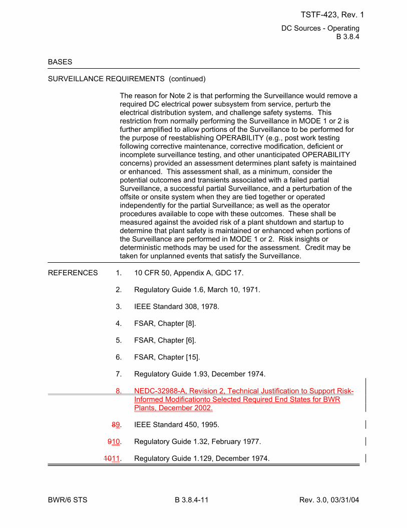
DC Sources - Operating B 3.8.4
BWR/6 STS B 3.8.4-11 Rev. 3.0, 03/31/04
BASES SURVEILLANCE REQUIREMENTS (continued)
The reason for Note 2 is that performing the Surveillance would remove a required DC electrical power subsystem from service, perturb the electrical distribution system, and challenge safety systems. This restriction from normally performing the Surveillance in MODE 1 or 2 is further amplified to allow portions of the Surveillance to be performed for the purpose of reestablishing OPERABILITY (e.g., post work testing following corrective maintenance, corrective modification, deficient or incomplete surveillance testing, and other unanticipated OPERABILITY concerns) provided an assessment determines plant safety is maintained or enhanced. This assessment shall, as a minimum, consider the potential outcomes and transients associated with a failed partial Surveillance, a successful partial Surveillance, and a perturbation of the offsite or onsite system when they are tied together or operated independently for the partial Surveillance; as well as the operator procedures available to cope with these outcomes. These shall be measured against the avoided risk of a plant shutdown and startup to determine that plant safety is maintained or enhanced when portions of the Surveillance are performed in MODE 1 or 2. Risk insights or deterministic methods may be used for the assessment. Credit may be taken for unplanned events that satisfy the Surveillance.
REFERENCES 1. 10 CFR 50, Appendix A, GDC 17. 2. Regulatory Guide 1.6, March 10, 1971. 3. IEEE Standard 308, 1978. 4. FSAR, Chapter [8]. 5. FSAR, Chapter [6]. 6. FSAR, Chapter [15]. 7. Regulatory Guide 1.93, December 1974. 8. NEDC-32988-A, Revision 2, Technical Justification to Support Risk-
Informed Modificationto Selected Required End States for BWR Plants, December 2002.
89. IEEE Standard 450, 1995. 910. Regulatory Guide 1.32, February 1977. 1011. Regulatory Guide 1.129, December 1974.
TSTF-423, Rev. 1
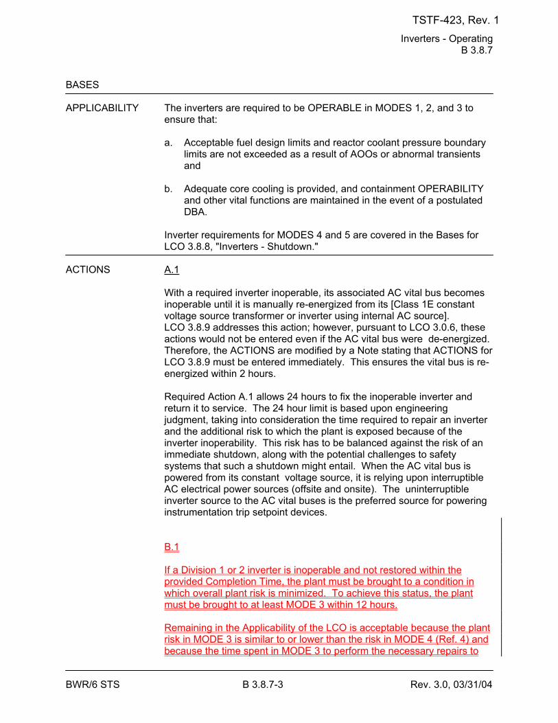
Inverters - Operating B 3.8.7
BWR/6 STS B 3.8.7-3 Rev. 3.0, 03/31/04
BASES APPLICABILITY The inverters are required to be OPERABLE in MODES 1, 2, and 3 to
ensure that:
a. Acceptable fuel design limits and reactor coolant pressure boundary limits are not exceeded as a result of AOOs or abnormal transients and
b. Adequate core cooling is provided, and containment OPERABILITY
and other vital functions are maintained in the event of a postulated DBA.
Inverter requirements for MODES 4 and 5 are covered in the Bases for LCO 3.8.8, "Inverters - Shutdown."
ACTIONS A.1
With a required inverter inoperable, its associated AC vital bus becomes inoperable until it is manually re-energized from its [Class 1E constant voltage source transformer or inverter using internal AC source]. LCO 3.8.9 addresses this action; however, pursuant to LCO 3.0.6, these actions would not be entered even if the AC vital bus were de-energized. Therefore, the ACTIONS are modified by a Note stating that ACTIONS for LCO 3.8.9 must be entered immediately. This ensures the vital bus is re-energized within 2 hours. Required Action A.1 allows 24 hours to fix the inoperable inverter and return it to service. The 24 hour limit is based upon engineering judgment, taking into consideration the time required to repair an inverter and the additional risk to which the plant is exposed because of the inverter inoperability. This risk has to be balanced against the risk of an immediate shutdown, along with the potential challenges to safety systems that such a shutdown might entail. When the AC vital bus is powered from its constant voltage source, it is relying upon interruptible AC electrical power sources (offsite and onsite). The uninterruptible inverter source to the AC vital buses is the preferred source for powering instrumentation trip setpoint devices. B.1 If a Division 1 or 2 inverter is inoperable and not restored within the provided Completion Time, the plant must be brought to a condition in which overall plant risk is minimized. To achieve this status, the plant must be brought to at least MODE 3 within 12 hours. Remaining in the Applicability of the LCO is acceptable because the plant risk in MODE 3 is similar to or lower than the risk in MODE 4 (Ref. 4) and because the time spent in MODE 3 to perform the necessary repairs to
TSTF-423, Rev. 1
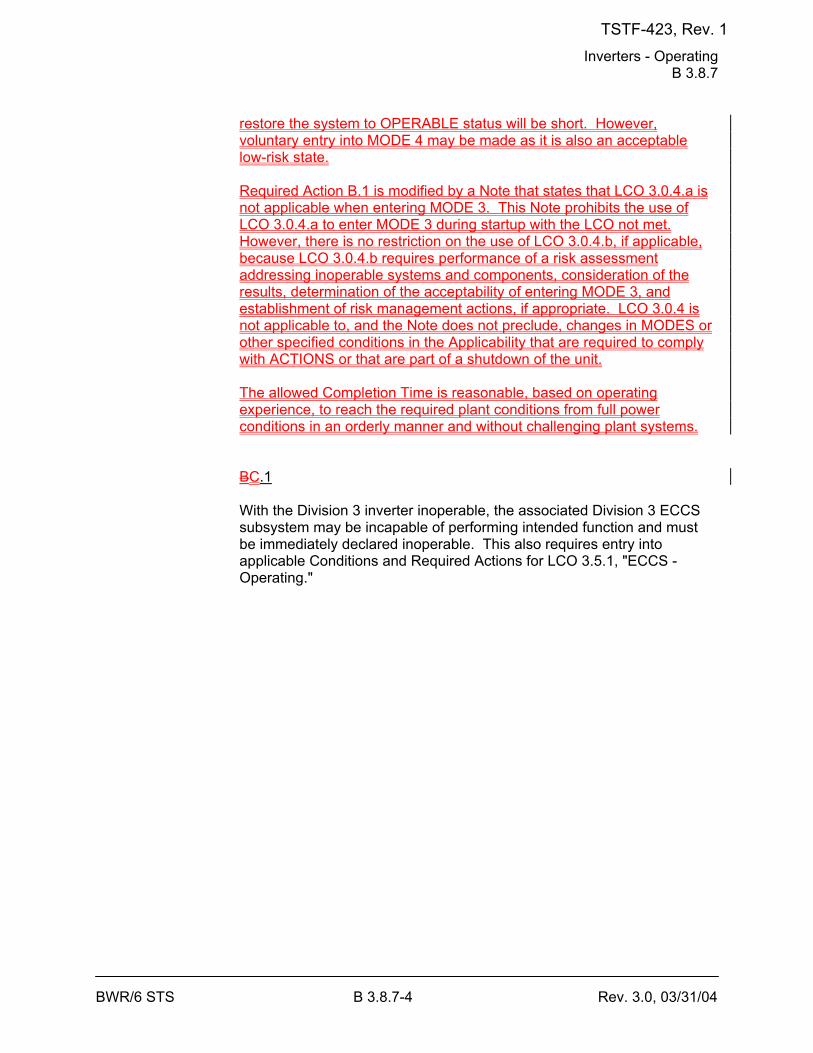
Inverters - Operating B 3.8.7
BWR/6 STS B 3.8.7-4 Rev. 3.0, 03/31/04
restore the system to OPERABLE status will be short. However, voluntary entry into MODE 4 may be made as it is also an acceptable low-risk state. Required Action B.1 is modified by a Note that states that LCO 3.0.4.a is not applicable when entering MODE 3. This Note prohibits the use of LCO 3.0.4.a to enter MODE 3 during startup with the LCO not met. However, there is no restriction on the use of LCO 3.0.4.b, if applicable, because LCO 3.0.4.b requires performance of a risk assessment addressing inoperable systems and components, consideration of the results, determination of the acceptability of entering MODE 3, and establishment of risk management actions, if appropriate. LCO 3.0.4 is not applicable to, and the Note does not preclude, changes in MODES or other specified conditions in the Applicability that are required to comply with ACTIONS or that are part of a shutdown of the unit. The allowed Completion Time is reasonable, based on operating experience, to reach the required plant conditions from full power conditions in an orderly manner and without challenging plant systems. BC.1 With the Division 3 inverter inoperable, the associated Division 3 ECCS subsystem may be incapable of performing intended function and must be immediately declared inoperable. This also requires entry into applicable Conditions and Required Actions for LCO 3.5.1, "ECCS - Operating."
TSTF-423, Rev. 1
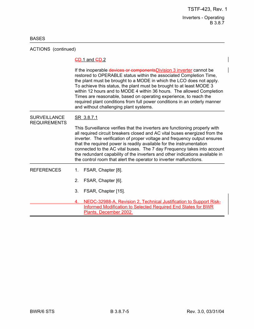
Inverters - Operating B 3.8.7
BWR/6 STS B 3.8.7-5 Rev. 3.0, 03/31/04
BASES ACTIONS (continued)
CD.1 and CD.2 If the inoperable devices or componentsDivision 3 inverter cannot be restored to OPERABLE status within the associated Completion Time, the plant must be brought to a MODE in which the LCO does not apply. To achieve this status, the plant must be brought to at least MODE 3 within 12 hours and to MODE 4 within 36 hours. The allowed Completion Times are reasonable, based on operating experience, to reach the required plant conditions from full power conditions in an orderly manner and without challenging plant systems.
SURVEILLANCE SR 3.8.7.1 REQUIREMENTS
This Surveillance verifies that the inverters are functioning properly with all required circuit breakers closed and AC vital buses energized from the inverter. The verification of proper voltage and frequency output ensures that the required power is readily available for the instrumentation connected to the AC vital buses. The 7 day Frequency takes into account the redundant capability of the inverters and other indications available in the control room that alert the operator to inverter malfunctions.
REFERENCES 1. FSAR, Chapter [8]. 2. FSAR, Chapter [6]. 3. FSAR, Chapter [15]. 4. NEDC-32988-A, Revision 2, Technical Justification to Support Risk-
Informed Modification to Selected Required End States for BWR Plants, December 2002.
TSTF-423, Rev. 1
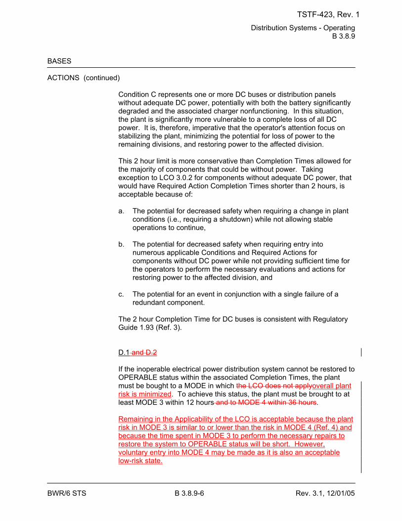
Distribution Systems - Operating B 3.8.9
BWR/6 STS B 3.8.9-6 Rev. 3.1, 12/01/05
BASES ACTIONS (continued)
Condition C represents one or more DC buses or distribution panels without adequate DC power, potentially with both the battery significantly degraded and the associated charger nonfunctioning. In this situation, the plant is significantly more vulnerable to a complete loss of all DC power. It is, therefore, imperative that the operator's attention focus on stabilizing the plant, minimizing the potential for loss of power to the remaining divisions, and restoring power to the affected division. This 2 hour limit is more conservative than Completion Times allowed for the majority of components that could be without power. Taking exception to LCO 3.0.2 for components without adequate DC power, that would have Required Action Completion Times shorter than 2 hours, is acceptable because of: a. The potential for decreased safety when requiring a change in plant
conditions (i.e., requiring a shutdown) while not allowing stable operations to continue,
b. The potential for decreased safety when requiring entry into
numerous applicable Conditions and Required Actions for components without DC power while not providing sufficient time for the operators to perform the necessary evaluations and actions for restoring power to the affected division, and
c. The potential for an event in conjunction with a single failure of a
redundant component. The 2 hour Completion Time for DC buses is consistent with Regulatory Guide 1.93 (Ref. 3). D.1 and D.2 If the inoperable electrical power distribution system cannot be restored to OPERABLE status within the associated Completion Times, the plant must be bought to a MODE in which the LCO does not applyoverall plant risk is minimized. To achieve this status, the plant must be brought to at least MODE 3 within 12 hours and to MODE 4 within 36 hours. Remaining in the Applicability of the LCO is acceptable because the plant risk in MODE 3 is similar to or lower than the risk in MODE 4 (Ref. 4) and because the time spent in MODE 3 to perform the necessary repairs to restore the system to OPERABLE status will be short. However, voluntary entry into MODE 4 may be made as it is also an acceptable low-risk state.
TSTF-423, Rev. 1

Distribution Systems - Operating B 3.8.9
BWR/6 STS B 3.8.9-7 Rev. 3.1, 12/01/05
Required Action D.1 is modified by a Note that states that LCO 3.0.4.a is not applicable when entering MODE 3. This Note prohibits the use of LCO 3.0.4.a to enter MODE 3 during startup with the LCO not met. However, there is no restriction on the use of LCO 3.0.4.b, if applicable, because LCO 3.0.4.b requires performance of a risk assessment addressing inoperable systems and components, consideration of the results, determination of the acceptability of entering MODE 3, and establishment of risk management actions, if appropriate. LCO 3.0.4 is not applicable to, and the Note does not preclude, changes in MODES or other specified conditions in the Applicability that are required to comply with ACTIONS or that are part of a shutdown of the unit. The allowed Completion Times areis reasonable, based on operating experience, to reach the required plant conditions from full power conditions in an orderly manner and without challenging plant systems.
TSTF-423, Rev. 1
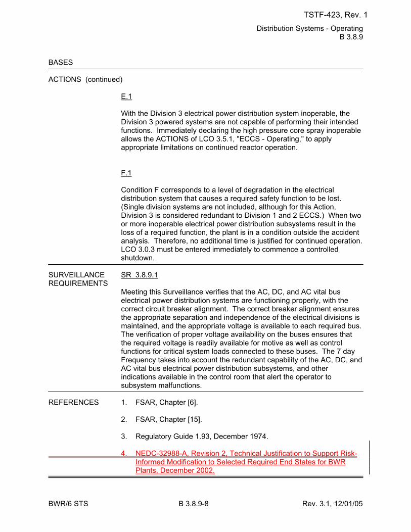
Distribution Systems - Operating B 3.8.9
BWR/6 STS B 3.8.9-8 Rev. 3.1, 12/01/05
BASES ACTIONS (continued)
E.1 With the Division 3 electrical power distribution system inoperable, the Division 3 powered systems are not capable of performing their intended functions. Immediately declaring the high pressure core spray inoperable allows the ACTIONS of LCO 3.5.1, "ECCS - Operating," to apply appropriate limitations on continued reactor operation. F.1 Condition F corresponds to a level of degradation in the electrical distribution system that causes a required safety function to be lost. (Single division systems are not included, although for this Action, Division 3 is considered redundant to Division 1 and 2 ECCS.) When two or more inoperable electrical power distribution subsystems result in the loss of a required function, the plant is in a condition outside the accident analysis. Therefore, no additional time is justified for continued operation. LCO 3.0.3 must be entered immediately to commence a controlled shutdown.
SURVEILLANCE SR 3.8.9.1 REQUIREMENTS
Meeting this Surveillance verifies that the AC, DC, and AC vital bus electrical power distribution systems are functioning properly, with the correct circuit breaker alignment. The correct breaker alignment ensures the appropriate separation and independence of the electrical divisions is maintained, and the appropriate voltage is available to each required bus. The verification of proper voltage availability on the buses ensures that the required voltage is readily available for motive as well as control functions for critical system loads connected to these buses. The 7 day Frequency takes into account the redundant capability of the AC, DC, and AC vital bus electrical power distribution subsystems, and other indications available in the control room that alert the operator to subsystem malfunctions.
REFERENCES 1. FSAR, Chapter [6]. 2. FSAR, Chapter [15]. 3. Regulatory Guide 1.93, December 1974. 4. NEDC-32988-A, Revision 2, Technical Justification to Support Risk-
Informed Modification to Selected Required End States for BWR Plants, December 2002.
TSTF-423, Rev. 1
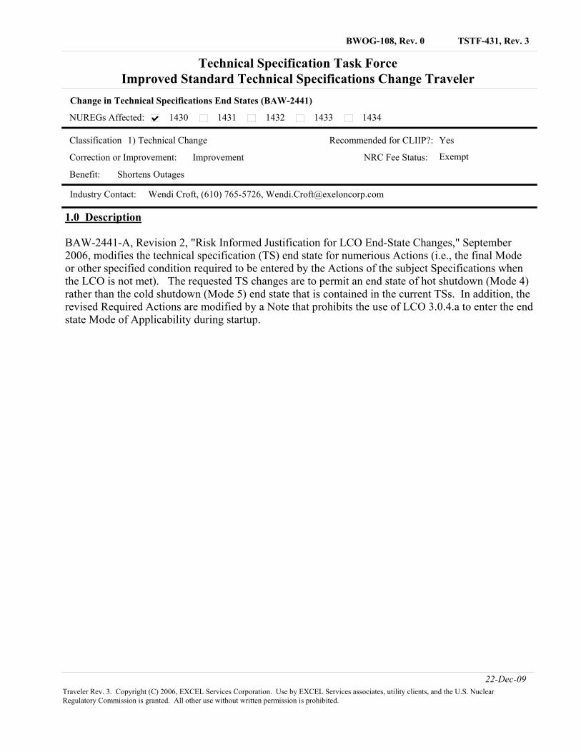
TSTF-431, Rev. 3BWOG-108, Rev. 0
NUREGs Affected:
Change in Technical Specifications End States (BAW-2441)
Technical Specification Task ForceImproved Standard Technical Specifications Change Traveler
1430 1431 1432 1433 1434
Classification 1) Technical Change Recommended for CLIIP?:
Industry Contact: Wendi Croft, (610) 765-5726, [email protected]
Yes
Correction or Improvement: Improvement NRC Fee Status: Exempt
Benefit: Shortens Outages
1.0 Description
BAW-2441-A, Revision 2, "Risk Informed Justification for LCO End-State Changes," September 2006, modifies the technical specification (TS) end state for numerious Actions (i.e., the final Mode or other specified condition required to be entered by the Actions of the subject Specifications when the LCO is not met). The requested TS changes are to permit an end state of hot shutdown (Mode 4) rather than the cold shutdown (Mode 5) end state that is contained in the current TSs. In addition, the revised Required Actions are modified by a Note that prohibits the use of LCO 3.0.4.a to enter the end state Mode of Applicability during startup.
22-Dec-09Traveler Rev. 3. Copyright (C) 2006, EXCEL Services Corporation. Use by EXCEL Services associates, utility clients, and the U.S. Nuclear Regulatory Commission is granted. All other use without written permission is prohibited.
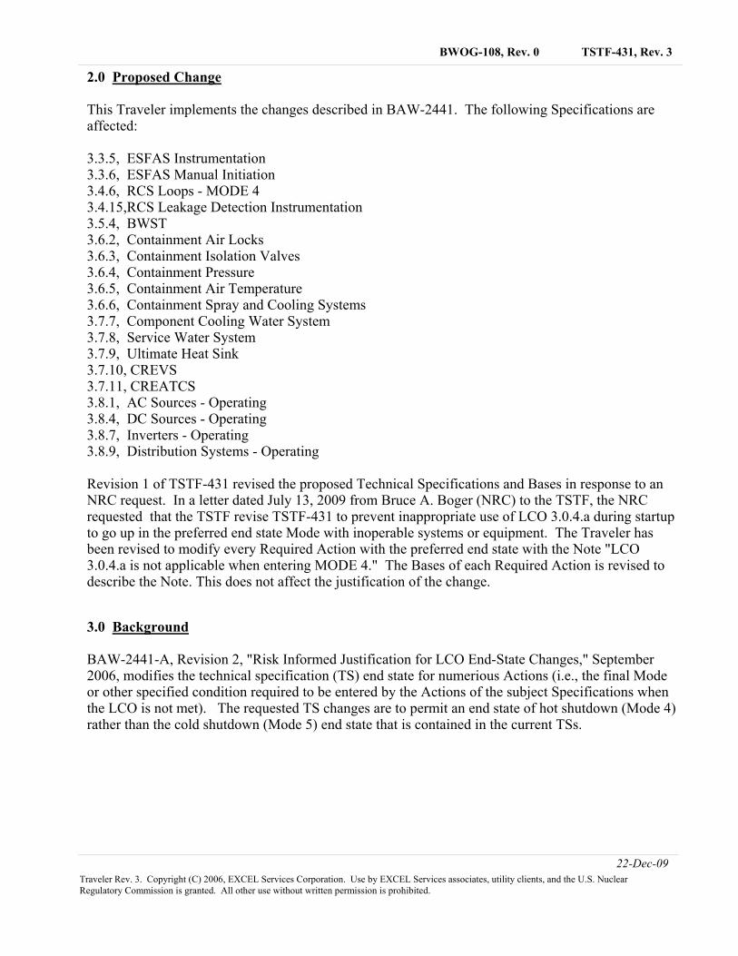
TSTF-431, Rev. 3BWOG-108, Rev. 0
2.0 Proposed Change
This Traveler implements the changes described in BAW-2441. The following Specifications are affected:
3.3.5, ESFAS Instrumentation3.3.6, ESFAS Manual Initiation3.4.6, RCS Loops - MODE 43.4.15,RCS Leakage Detection Instrumentation3.5.4, BWST3.6.2, Containment Air Locks3.6.3, Containment Isolation Valves3.6.4, Containment Pressure3.6.5, Containment Air Temperature3.6.6, Containment Spray and Cooling Systems3.7.7, Component Cooling Water System3.7.8, Service Water System3.7.9, Ultimate Heat Sink3.7.10, CREVS3.7.11, CREATCS3.8.1, AC Sources - Operating3.8.4, DC Sources - Operating3.8.7, Inverters - Operating3.8.9, Distribution Systems - Operating
Revision 1 of TSTF-431 revised the proposed Technical Specifications and Bases in response to an NRC request. In a letter dated July 13, 2009 from Bruce A. Boger (NRC) to the TSTF, the NRC requested that the TSTF revise TSTF-431 to prevent inappropriate use of LCO 3.0.4.a during startup to go up in the preferred end state Mode with inoperable systems or equipment. The Traveler has been revised to modify every Required Action with the preferred end state with the Note "LCO 3.0.4.a is not applicable when entering MODE 4." The Bases of each Required Action is revised to describe the Note. This does not affect the justification of the change.
3.0 Background
BAW-2441-A, Revision 2, "Risk Informed Justification for LCO End-State Changes," September 2006, modifies the technical specification (TS) end state for numerious Actions (i.e., the final Mode or other specified condition required to be entered by the Actions of the subject Specifications when the LCO is not met). The requested TS changes are to permit an end state of hot shutdown (Mode 4) rather than the cold shutdown (Mode 5) end state that is contained in the current TSs.
22-Dec-09Traveler Rev. 3. Copyright (C) 2006, EXCEL Services Corporation. Use by EXCEL Services associates, utility clients, and the U.S. Nuclear Regulatory Commission is granted. All other use without written permission is prohibited.
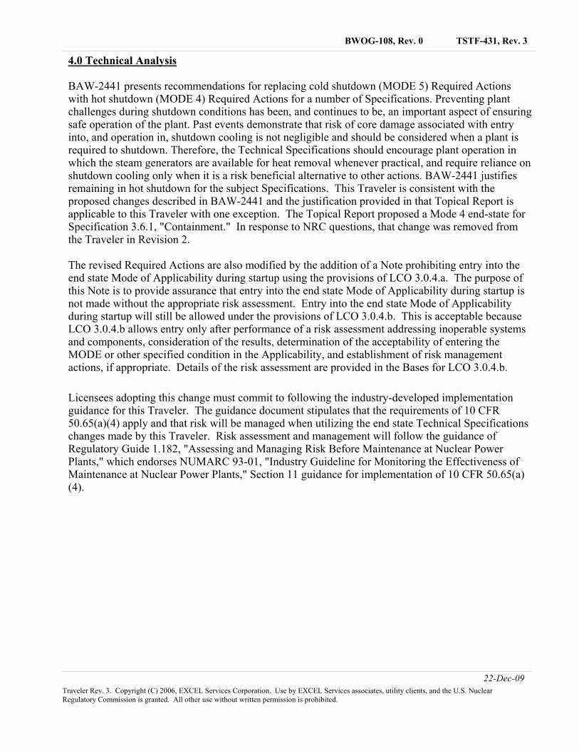
TSTF-431, Rev. 3BWOG-108, Rev. 0
4.0 Technical Analysis
BAW-2441 presents recommendations for replacing cold shutdown (MODE 5) Required Actions with hot shutdown (MODE 4) Required Actions for a number of Specifications. Preventing plant challenges during shutdown conditions has been, and continues to be, an important aspect of ensuring safe operation of the plant. Past events demonstrate that risk of core damage associated with entry into, and operation in, shutdown cooling is not negligible and should be considered when a plant is required to shutdown. Therefore, the Technical Specifications should encourage plant operation in which the steam generators are available for heat removal whenever practical, and require reliance on shutdown cooling only when it is a risk beneficial alternative to other actions. BAW-2441 justifies remaining in hot shutdown for the subject Specifications. This Traveler is consistent with the proposed changes described in BAW-2441 and the justification provided in that Topical Report is applicable to this Traveler with one exception. The Topical Report proposed a Mode 4 end-state for Specification 3.6.1, "Containment." In response to NRC questions, that change was removed from the Traveler in Revision 2.
The revised Required Actions are also modified by the addition of a Note prohibiting entry into the end state Mode of Applicability during startup using the provisions of LCO 3.0.4.a. The purpose of this Note is to provide assurance that entry into the end state Mode of Applicability during startup is not made without the appropriate risk assessment. Entry into the end state Mode of Applicability during startup will still be allowed under the provisions of LCO 3.0.4.b. This is acceptable because LCO 3.0.4.b allows entry only after performance of a risk assessment addressing inoperable systems and components, consideration of the results, determination of the acceptability of entering the MODE or other specified condition in the Applicability, and establishment of risk management actions, if appropriate. Details of the risk assessment are provided in the Bases for LCO 3.0.4.b.
Licensees adopting this change must commit to following the industry-developed implementation guidance for this Traveler. The guidance document stipulates that the requirements of 10 CFR 50.65(a)(4) apply and that risk will be managed when utilizing the end state Technical Specifications changes made by this Traveler. Risk assessment and management will follow the guidance of Regulatory Guide 1.182, "Assessing and Managing Risk Before Maintenance at Nuclear Power Plants," which endorses NUMARC 93-01, "Industry Guideline for Monitoring the Effectiveness of Maintenance at Nuclear Power Plants," Section 11 guidance for implementation of 10 CFR 50.65(a)(4).
22-Dec-09Traveler Rev. 3. Copyright (C) 2006, EXCEL Services Corporation. Use by EXCEL Services associates, utility clients, and the U.S. Nuclear Regulatory Commission is granted. All other use without written permission is prohibited.
TSTF-431, Rev. 3BWOG-108, Rev. 0
5.0 Regulatory Analysis
5.1 No Significant Hazards Consideration
The TSTF has evaluated whether or not a significant hazards consideration is involved with the proposed generic change by focusing on the three standards set forth in 10 CFR 50.92, "Issuance of amendment," as discussed below:
1. Does the proposed change involve a significant increase in the probability or consequences of an accident previously evaluated?
Response: No.
The proposed change modifies the end state (e.g., mode or other specified condition) which the Required Actions specify must be entered if compliance with the LCO is not restored. Required Actions are not an initiator of any accident previously evaluated. Therefore, the proposed changes do not affect the probability of any accident previously evaluated. BAW-2441 demonstrates that the proposed changes in the required end state do not significantly increase the consequences of any accidents previously evaluated.
Therefore, the proposed change does not involve a significant increase in the probability or consequences of an accident previously evaluated.
2. Does the proposed change create the possibility of a new or different kind of accident from any accident previously evaluated?
Response: No.
The changes do not involve a physical alteration of the plant (i.e., no new or different type ofequipment will be installed) or a change in the methods governing normal plant operation. Inaddition, the changes do not impose any new requirements. The changes do not alter assumptionsmade in the safety analysis.
Therefore, the proposed change does not create the possibility of a new or different kind of accident from any accident previously evaluated.
3. Does the proposed change involve a significant reduction in a margin of safety?
Response: No.
BAW-2441 demonstrates that the changed end states represent a condition of equal or lower risk than the original end states.
Therefore, the proposed change does not involve a significant reduction in a margin of safety.
Based on the above, the TSTF concludes that the proposed change presents no significant hazards consideration under the standards set forth in 10 CFR 50.92(c), and, accordingly, a finding of "no significant hazards consideration" is justified.
22-Dec-09Traveler Rev. 3. Copyright (C) 2006, EXCEL Services Corporation. Use by EXCEL Services associates, utility clients, and the U.S. Nuclear Regulatory Commission is granted. All other use without written permission is prohibited.
TSTF-431, Rev. 3BWOG-108, Rev. 0
5.2 Applicable Regulatory Requirements/Criteria
Required Actions are not specified by any regulatory requirement or criteria. The Limiting Conditions for Operation, which are based on accident analysis assumptions and regulatory requirements are not affected by this change. Therefore, no regulatory requirements or criteria are affected by this change.
In conclusion, based on the considerations discussed above, (1) there is reasonable assurance that the health and safety of the public will not be endangered by operation in the proposed manner, (2) such activities will be conducted in compliance with the Commission’s regulations, and (3) the approval of the proposed change will not be inimical to the common defense and security or to the health and safety of the public.
6.0 Environmental Consideration
A review has determined that the proposed change would change a requirement with respect to installation or use of a facility component located within the restricted area, as defined in 10 CFR 20, or would change an inspection or surveillance requirement. However, the proposed change does not involve (i) a significant hazards consideration, (ii) a significant change in the types or significant increase in the amounts of any effluents that may be released offsite, or (iii) a significant increase in individual or cumulative occupational radiation exposure. Accordingly, the proposed change meets the eligibility criterion for categorical exclusion set forth in 10 CFR 51.22(c)(9). Therefore, pursuant to 10 CFR 51.22(b), no environmental impact statement or environmental assessment need be prepared in connection with the proposed change.
7.0 References
1. BAW-2441-A, Revision 2, Risk Informed Justification for LCO End-State Changes, September 2006.
Revision History
OG Revision 0 Revision Status: Closed
Original IssueRevision Description:
Revision Proposed by: BWOG
22-Dec-09Traveler Rev. 3. Copyright (C) 2006, EXCEL Services Corporation. Use by EXCEL Services associates, utility clients, and the U.S. Nuclear Regulatory Commission is granted. All other use without written permission is prohibited.
TSTF-431, Rev. 3BWOG-108, Rev. 0
OG Revision 0 Revision Status: Closed
Owners Group Review InformationDate Originated by OG: 27-Jul-04
Owners Group CommentsWithdrawn pending revision of the Topical Report.
Date:Owners Group Resolution: Withdrawn
TSTF Revision 1 Revision Status: Closed
References to the Topical Report, BAW-2441-A, were updated. Various editorial corrections were made. Pages were remarked on Revision 3.1 of the NUREG-1430.
Revision Description:
Revision Proposed by: BWOG
Owners Group Review InformationDate Originated by OG: 19-Sep-06
Owners Group Comments(No Comments)
Date: 19-Oct-06Owners Group Resolution: Approved
TSTF Review Information
TSTF Received Date: 20-Oct-06 Date Distributed for Review 20-Oct-06
TSTF Comments:
(No Comments)
Date: 03-Nov-06TSTF Resolution: Approved
OG Review Completed: BWOG CEOGWOG BWROG
NRC Review Information
NRC Received Date: 03-Nov-06
NRC RAI received on 5/3/2007. Response submitted on 7/9/07.
On a teleconference on 7/12/07, the NRC disagreed with the justification provided to support a mode 4 end state for Containment.
12-Jul-07NRC Requests Changes: TSTF Will Revise
NRC Comments:
Final Resolution: Final Resolution Date:
TSTF Revision 2 Revision Status: Closed
On a teleconference on 7/12/07, the NRC did not agree with the arguments put forth in the 7/9/07 RAI Revision Description:
Revision Proposed by: NRC
22-Dec-09Traveler Rev. 3. Copyright (C) 2006, EXCEL Services Corporation. Use by EXCEL Services associates, utility clients, and the U.S. Nuclear Regulatory Commission is granted. All other use without written permission is prohibited.
TSTF-431, Rev. 3BWOG-108, Rev. 0
TSTF Revision 2 Revision Status: Closed
response supporting a Mode 4 end state for Specification 3.6.1, Containment. Subsequently, the TSTF decided to remove the Mode 4 end state change for Specification 3.6.1.
TSTF Review Information
TSTF Received Date: 13-Jul-07 Date Distributed for Review 13-Jul-07
TSTF Comments:
(No Comments)
Date: 13-Jul-07TSTF Resolution: Approved
OG Review Completed: BWOG CEOGWOG BWROG
NRC Review InformationNRC Received Date: 13-Jul-07
In a letter dated July 13, 2009 from Bruce A. Boger (NRC) to the TSTF, the NRC requested that the TSTF revise TSTF-431 to prevent inappropriate use of LCO 3.0.4.a during startup to go up in the preferred end state Mode with inoperable systems or equipment. The Traveler has been revised to modify every Required Action with the preferred end state with the Note "LCO 3.0.4.a is not applicable when entering MODE 4." The Bases of each Required Action is revised to describe the Note.
NRC Requests Changes: TSTF Will Revise
NRC Comments:
Final Resolution:
TSTF Revision 3 Revision Status: Active
In a letter dated July 13, 2009 from Bruce A. Boger (NRC) to the TSTF, the NRC requested that the TSTF revise TSTF-431 to prevent inappropriate use of LCO 3.0.4.a during startup to go up in the preferred end state Mode with inoperable systems or equipment. The Traveler has been revised to modify every Required Action with the preferred end state with the Note "LCO 3.0.4.a is not applicable when entering MODE 4." The Bases of each Required Action is revised to describe the Note.
Revision Description:
Revision Proposed by: NRC
Owners Group Review InformationDate Originated by OG: 02-Nov-09
Owners Group Comments(No Comments)
Date: 16-Nov-09Owners Group Resolution: Approved
TSTF Review Information
TSTF Received Date: 16-Nov-09 Date Distributed for Review 14-Dec-09
TSTF Comments:
OG Review Completed: BWOG CEOGWOG BWROG
22-Dec-09Traveler Rev. 3. Copyright (C) 2006, EXCEL Services Corporation. Use by EXCEL Services associates, utility clients, and the U.S. Nuclear Regulatory Commission is granted. All other use without written permission is prohibited.
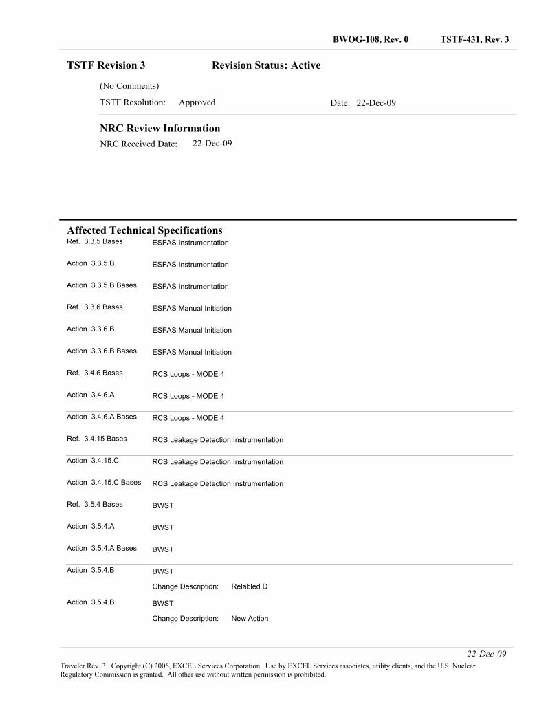
TSTF-431, Rev. 3BWOG-108, Rev. 0
Affected Technical Specifications
TSTF Revision 3 Revision Status: Active
(No Comments)
Date: 22-Dec-09TSTF Resolution: Approved
NRC Review InformationNRC Received Date: 22-Dec-09
Ref. 3.3.5 Bases ESFAS Instrumentation
Action 3.3.5.B ESFAS Instrumentation
Action 3.3.5.B Bases ESFAS Instrumentation
Ref. 3.3.6 Bases ESFAS Manual Initiation
Action 3.3.6.B ESFAS Manual Initiation
Action 3.3.6.B Bases ESFAS Manual Initiation
Ref. 3.4.6 Bases RCS Loops - MODE 4
Action 3.4.6.A RCS Loops - MODE 4
Action 3.4.6.A Bases RCS Loops - MODE 4
Ref. 3.4.15 Bases RCS Leakage Detection Instrumentation
Action 3.4.15.C RCS Leakage Detection Instrumentation
Action 3.4.15.C Bases RCS Leakage Detection Instrumentation
Ref. 3.5.4 Bases BWST
Action 3.5.4.A BWST
Action 3.5.4.A Bases BWST
Action 3.5.4.B
Relabled DChange Description:
BWST
Action 3.5.4.B
New ActionChange Description:
BWST
22-Dec-09Traveler Rev. 3. Copyright (C) 2006, EXCEL Services Corporation. Use by EXCEL Services associates, utility clients, and the U.S. Nuclear Regulatory Commission is granted. All other use without written permission is prohibited.
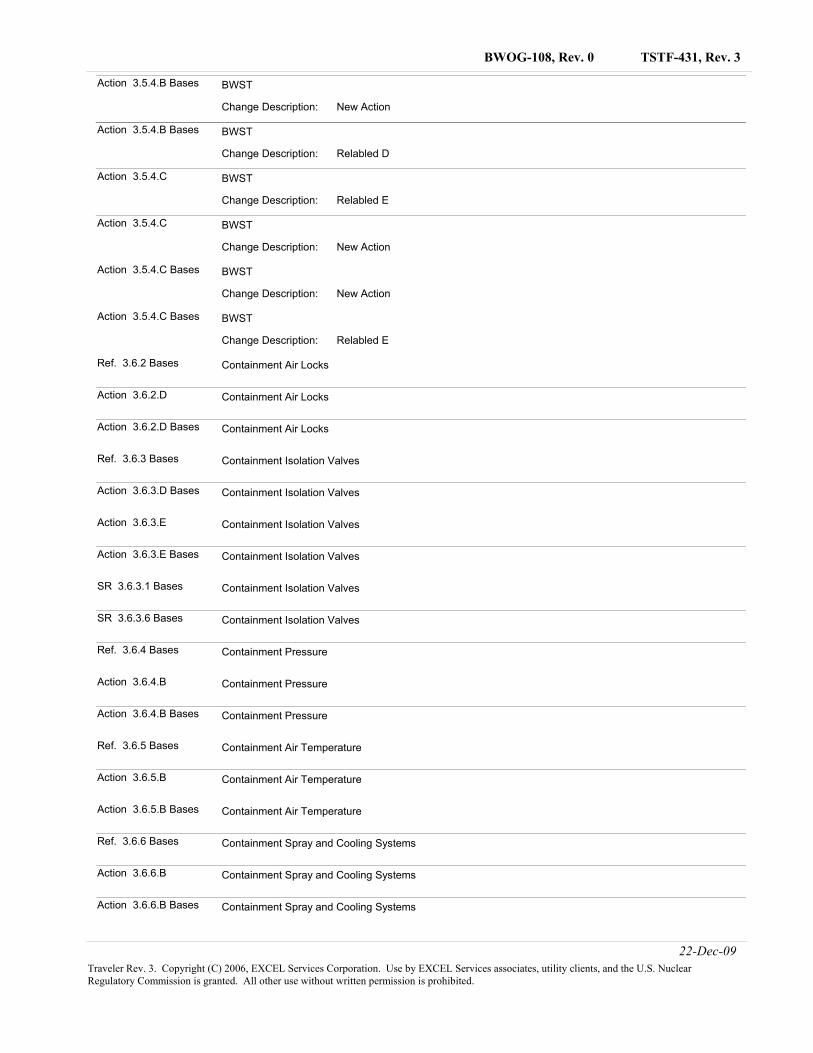
TSTF-431, Rev. 3BWOG-108, Rev. 0
Action 3.5.4.B Bases
New ActionChange Description:
BWST
Action 3.5.4.B Bases
Relabled DChange Description:
BWST
Action 3.5.4.C
Relabled EChange Description:
BWST
Action 3.5.4.C
New ActionChange Description:
BWST
Action 3.5.4.C Bases
New ActionChange Description:
BWST
Action 3.5.4.C Bases
Relabled EChange Description:
BWST
Ref. 3.6.2 Bases Containment Air Locks
Action 3.6.2.D Containment Air Locks
Action 3.6.2.D Bases Containment Air Locks
Ref. 3.6.3 Bases Containment Isolation Valves
Action 3.6.3.D Bases Containment Isolation Valves
Action 3.6.3.E Containment Isolation Valves
Action 3.6.3.E Bases Containment Isolation Valves
SR 3.6.3.1 Bases Containment Isolation Valves
SR 3.6.3.6 Bases Containment Isolation Valves
Ref. 3.6.4 Bases Containment Pressure
Action 3.6.4.B Containment Pressure
Action 3.6.4.B Bases Containment Pressure
Ref. 3.6.5 Bases Containment Air Temperature
Action 3.6.5.B Containment Air Temperature
Action 3.6.5.B Bases Containment Air Temperature
Ref. 3.6.6 Bases Containment Spray and Cooling Systems
Action 3.6.6.B Containment Spray and Cooling Systems
Action 3.6.6.B Bases Containment Spray and Cooling Systems
22-Dec-09Traveler Rev. 3. Copyright (C) 2006, EXCEL Services Corporation. Use by EXCEL Services associates, utility clients, and the U.S. Nuclear Regulatory Commission is granted. All other use without written permission is prohibited.
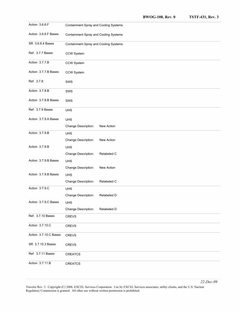
TSTF-431, Rev. 3BWOG-108, Rev. 0
Action 3.6.6.F Containment Spray and Cooling Systems
Action 3.6.6.F Bases Containment Spray and Cooling Systems
SR 3.6.6.4 Bases Containment Spray and Cooling Systems
Ref. 3.7.7 Bases CCW System
Action 3.7.7.B CCW System
Action 3.7.7.B Bases CCW System
Ref. 3.7.8 SWS
Action 3.7.8.B SWS
Action 3.7.8.B Bases SWS
Ref. 3.7.9 Bases UHS
Action 3.7.9.A Bases
New ActionChange Description:
UHS
Action 3.7.9.B
New ActionChange Description:
UHS
Action 3.7.9.B
Relabeled CChange Description:
UHS
Action 3.7.9.B Bases
New ActionChange Description:
UHS
Action 3.7.9.B Bases
Relabeled CChange Description:
UHS
Action 3.7.9.C
Relabeled DChange Description:
UHS
Action 3.7.9.C Bases
Relabeled DChange Description:
UHS
Ref. 3.7.10 Bases CREVS
Action 3.7.10.C CREVS
Action 3.7.10.C Bases CREVS
SR 3.7.10.3 Bases CREVS
Ref. 3.7.11 Bases CREATCS
Action 3.7.11.B CREATCS
22-Dec-09Traveler Rev. 3. Copyright (C) 2006, EXCEL Services Corporation. Use by EXCEL Services associates, utility clients, and the U.S. Nuclear Regulatory Commission is granted. All other use without written permission is prohibited.
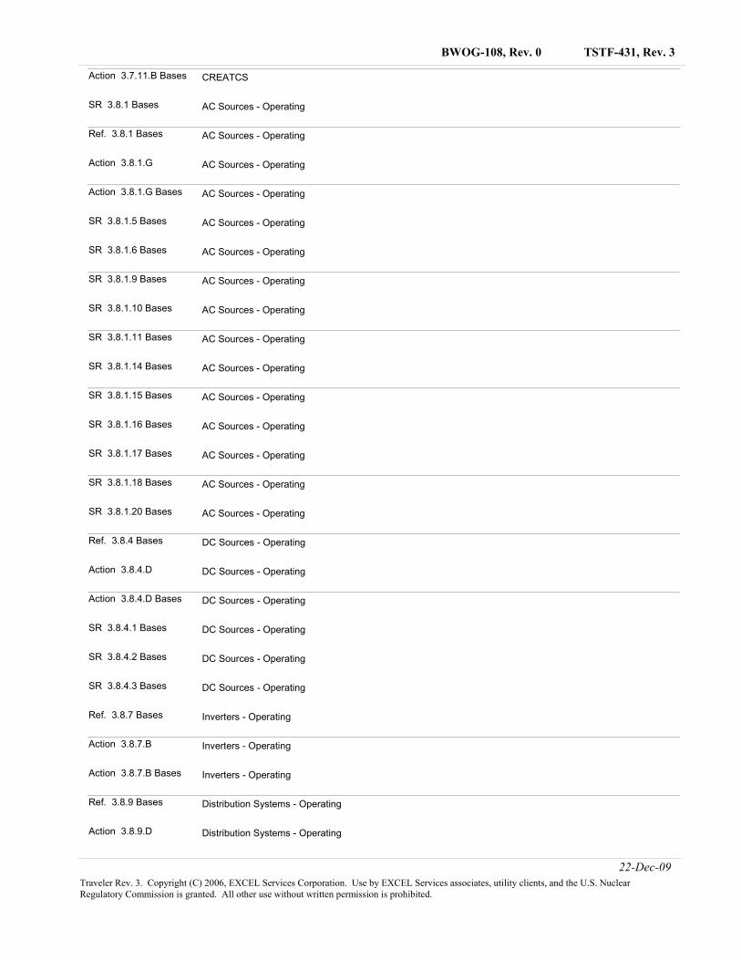
TSTF-431, Rev. 3BWOG-108, Rev. 0
Action 3.7.11.B Bases CREATCS
SR 3.8.1 Bases AC Sources - Operating
Ref. 3.8.1 Bases AC Sources - Operating
Action 3.8.1.G AC Sources - Operating
Action 3.8.1.G Bases AC Sources - Operating
SR 3.8.1.5 Bases AC Sources - Operating
SR 3.8.1.6 Bases AC Sources - Operating
SR 3.8.1.9 Bases AC Sources - Operating
SR 3.8.1.10 Bases AC Sources - Operating
SR 3.8.1.11 Bases AC Sources - Operating
SR 3.8.1.14 Bases AC Sources - Operating
SR 3.8.1.15 Bases AC Sources - Operating
SR 3.8.1.16 Bases AC Sources - Operating
SR 3.8.1.17 Bases AC Sources - Operating
SR 3.8.1.18 Bases AC Sources - Operating
SR 3.8.1.20 Bases AC Sources - Operating
Ref. 3.8.4 Bases DC Sources - Operating
Action 3.8.4.D DC Sources - Operating
Action 3.8.4.D Bases DC Sources - Operating
SR 3.8.4.1 Bases DC Sources - Operating
SR 3.8.4.2 Bases DC Sources - Operating
SR 3.8.4.3 Bases DC Sources - Operating
Ref. 3.8.7 Bases Inverters - Operating
Action 3.8.7.B Inverters - Operating
Action 3.8.7.B Bases Inverters - Operating
Ref. 3.8.9 Bases Distribution Systems - Operating
Action 3.8.9.D Distribution Systems - Operating
22-Dec-09Traveler Rev. 3. Copyright (C) 2006, EXCEL Services Corporation. Use by EXCEL Services associates, utility clients, and the U.S. Nuclear Regulatory Commission is granted. All other use without written permission is prohibited.
TSTF-431, Rev. 3BWOG-108, Rev. 0
Action 3.8.9.D Bases Distribution Systems - Operating
22-Dec-09Traveler Rev. 3. Copyright (C) 2006, EXCEL Services Corporation. Use by EXCEL Services associates, utility clients, and the U.S. Nuclear Regulatory Commission is granted. All other use without written permission is prohibited.
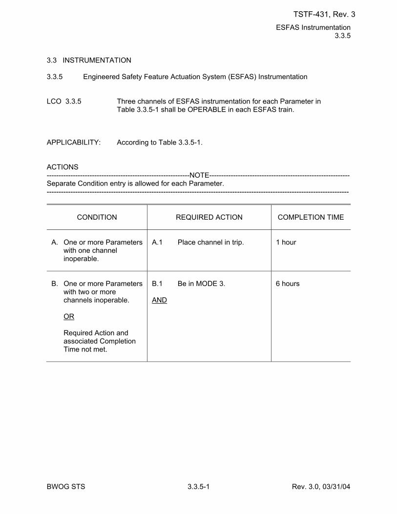
ESFAS Instrumentation 3.3.5
BWOG STS 3.3.5-1 Rev. 3.0, 03/31/04
3.3 INSTRUMENTATION 3.3.5 Engineered Safety Feature Actuation System (ESFAS) Instrumentation LCO 3.3.5 Three channels of ESFAS instrumentation for each Parameter in
Table 3.3.5-1 shall be OPERABLE in each ESFAS train. APPLICABILITY: According to Table 3.3.5-1. ACTIONS ------------------------------------------------------------NOTE----------------------------------------------------------- Separate Condition entry is allowed for each Parameter. -------------------------------------------------------------------------------------------------------------------------------
CONDITION
REQUIRED ACTION
COMPLETION TIME
A. One or more Parameters
with one channel inoperable.
A.1 Place channel in trip.
1 hour
B. One or more Parameters
with two or more channels inoperable.
OR Required Action and
associated Completion Time not met.
B.1 Be in MODE 3. AND
6 hours
TSTF-431, Rev. 3
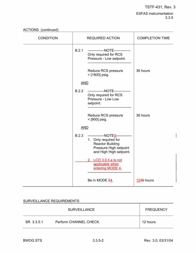
ESFAS Instrumentation 3.3.5
BWOG STS 3.3.5-2 Rev. 3.0, 03/31/04
ACTIONS (continued)
CONDITION
REQUIRED ACTION
COMPLETION TIME
B.2.1 --------------NOTE-------------- Only required for RCS
Pressure - Low setpoint. ------------------------------------- Reduce RCS pressure
< [1800] psig. AND B.2.2 --------------NOTE-------------- Only required for RCS
Pressure - Low Low setpoint.
------------------------------------- Reduce RCS pressure
< [900] psig. AND B.2.3 --------------NOTES------------- 1. Only required for
Reactor Building Pressure High setpoint and High High setpoint.
2. LCO 3.0.4.a is not
applicable when entering MODE 4.
------------------------------------- Be in MODE 54.
36 hours 36 hours 1236 hours
SURVEILLANCE REQUIREMENTS
SURVEILLANCE
FREQUENCY
SR 3.3.5.1 Perform CHANNEL CHECK.
12 hours
TSTF-431, Rev. 3
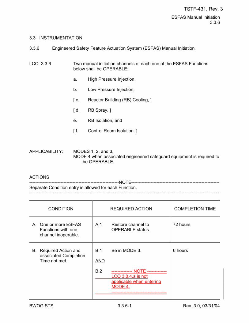
ESFAS Manual Initiation 3.3.6
BWOG STS 3.3.6-1 Rev. 3.0, 03/31/04
3.3 INSTRUMENTATION 3.3.6 Engineered Safety Feature Actuation System (ESFAS) Manual Initiation LCO 3.3.6 Two manual initiation channels of each one of the ESFAS Functions
below shall be OPERABLE: a. High Pressure Injection, b. Low Pressure Injection, [ c. Reactor Building (RB) Cooling, ] [ d. RB Spray, ] e. RB Isolation, and [ f. Control Room Isolation. ] APPLICABILITY: MODES 1, 2, and 3, MODE 4 when associated engineered safeguard equipment is required to
be OPERABLE. ACTIONS ------------------------------------------------------------NOTE----------------------------------------------------------- Separate Condition entry is allowed for each Function. -------------------------------------------------------------------------------------------------------------------------------
CONDITION
REQUIRED ACTION
COMPLETION TIME
A. One or more ESFAS
Functions with one channel inoperable.
A.1 Restore channel to
OPERABLE status.
72 hours
B. Required Action and
associated Completion Time not met.
B.1 Be in MODE 3. AND B.2 -------------- NOTE ------------- LCO 3.0.4.a is not
applicable when entering MODE 4.
-------------------------------------
6 hours
TSTF-431, Rev. 3
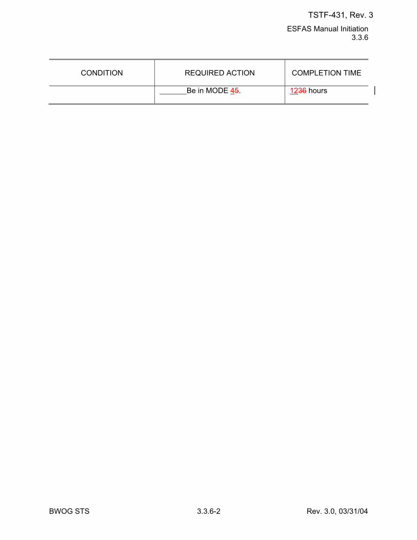
ESFAS Manual Initiation 3.3.6
BWOG STS 3.3.6-2 Rev. 3.0, 03/31/04
CONDITION
REQUIRED ACTION
COMPLETION TIME
Be in MODE 45.
1236 hours
TSTF-431, Rev. 3
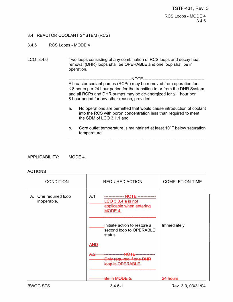
RCS Loops - MODE 4 3.4.6
BWOG STS 3.4.6-1 Rev. 3.0, 03/31/04
3.4 REACTOR COOLANT SYSTEM (RCS) 3.4.6 RCS Loops - MODE 4 LCO 3.4.6 Two loops consisting of any combination of RCS loops and decay heat
removal (DHR) loops shall be OPERABLE and one loop shall be in operation.
---------------------------------------------NOTE-------------------------------------------- All reactor coolant pumps (RCPs) may be removed from operation for
≤ 8 hours per 24 hour period for the transition to or from the DHR System, and all RCPs and DHR pumps may be de-energized for ≤ 1 hour per 8 hour period for any other reason, provided:
a. No operations are permitted that would cause introduction of coolant
into the RCS with boron concentration less than required to meet the SDM of LCO 3.1.1 and
b. Core outlet temperature is maintained at least 10°F below saturation
temperature. -------------------------------------------------------------------------------------------------- APPLICABILITY: MODE 4. ACTIONS
CONDITION
REQUIRED ACTION
COMPLETION TIME
A. One required loop
inoperable.
A.1 -------------- NOTE ------------- LCO 3.0.4.a is not
applicable when entering MODE 4.
------------------------------------- Initiate action to restore a
second loop to OPERABLE status.
AND A.2 --------------NOTE-------------- Only required if one DHR
loop is OPERABLE. ------------------------------------- Be in MODE 5.
Immediately 24 hours
TSTF-431, Rev. 3
RCS Loops - MODE 4 3.4.6
BWOG STS 3.4.6-2 Rev. 3.0, 03/31/04
CONDITION
REQUIRED ACTION
COMPLETION TIME
TSTF-431, Rev. 3
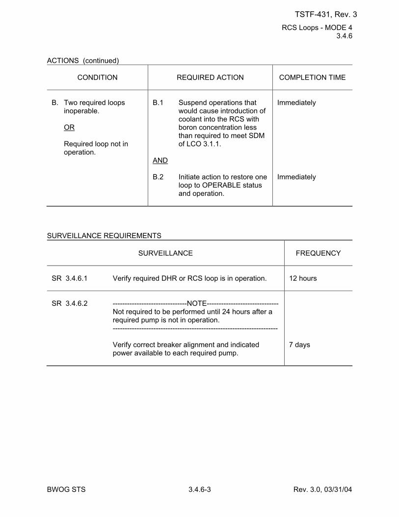
RCS Loops - MODE 4 3.4.6
BWOG STS 3.4.6-3 Rev. 3.0, 03/31/04
ACTIONS (continued)
CONDITION
REQUIRED ACTION
COMPLETION TIME
B. Two required loops
inoperable. OR Required loop not in
operation.
B.1 Suspend operations that
would cause introduction of coolant into the RCS with boron concentration less than required to meet SDM of LCO 3.1.1.
AND B.2 Initiate action to restore one
loop to OPERABLE status and operation.
Immediately Immediately
SURVEILLANCE REQUIREMENTS
SURVEILLANCE
FREQUENCY
SR 3.4.6.1 Verify required DHR or RCS loop is in operation.
12 hours
SR 3.4.6.2 -------------------------------NOTE------------------------------ Not required to be performed until 24 hours after a
required pump is not in operation. --------------------------------------------------------------------- Verify correct breaker alignment and indicated
power available to each required pump.
7 days
TSTF-431, Rev. 3
RCS Leakage Detection Instrumentation 3.4.15
BWOG STS 3.4.15-1 Rev. 3.0, 03/31/04
3.4 REACTOR COOLANT SYSTEM (RCS) 3.4.15 RCS Leakage Detection Instrumentation LCO 3.4.15 The following RCS leakage detection instrumentation shall be
OPERABLE: a. One containment sump monitor and b. One containment atmosphere radioactivity monitor (gaseous or
particulate). APPLICABILITY: MODES 1, 2, 3, and 4. ACTIONS
CONDITION
REQUIRED ACTION
COMPLETION TIME
A. Required containment
sump monitor inoperable.
A.1 --------------NOTE-------------- Not required until 12 hours
after establishment of steady state operation.
------------------------------------- Perform SR 3.4.13.1. AND A.2 Restore required
containment sump monitor to OPERABLE status.
Once per 24 hours 30 days
B. Required containment
atmosphere radioactivity monitor inoperable.
B.1.1 Analyze grab samples of
the containment atmosphere.
OR
Once per 24 hours
TSTF-431, Rev. 3
RCS Leakage Detection Instrumentation 3.4.15
BWOG STS 3.4.15-2 Rev. 3.0, 03/31/04
ACTIONS (continued)
CONDITION
REQUIRED ACTION
COMPLETION TIME
B.1.2 --------------NOTE-------------- Not required until 12 hours
after establishment of steady state operation.
------------------------------------- Perform SR 3.4.13.1. AND B.2 Restore required
containment atmosphere radioactivity monitor to OPERABLE status.
Once per 24 hours 30 days
C. Required Action and
associated Completion Time not met.
C.1 Be in MODE 3. AND C.2 -------------- NOTE ------------- LCO 3.0.4.a is not
applicable when entering MODE 4.
------------------------------------- Be in MODE 45.
6 hours 1236 hours
D. Both required monitors
inoperable.
D.1 Enter LCO 3.0.3.
Immediately
SURVEILLANCE REQUIREMENTS
SURVEILLANCE
FREQUENCY
SR 3.4.15.1 Perform CHANNEL CHECK of required containment
atmosphere radioactivity monitor.
12 hours
SR 3.4.15.2 Perform CHANNEL FUNCTIONAL TEST of required
containment atmosphere radioactivity monitor.
92 days
TSTF-431, Rev. 3
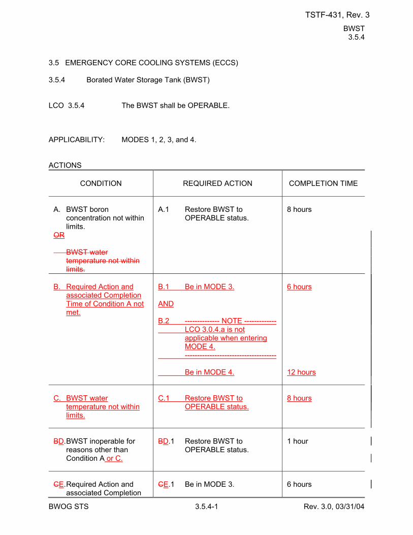
BWST 3.5.4
BWOG STS 3.5.4-1 Rev. 3.0, 03/31/04
3.5 EMERGENCY CORE COOLING SYSTEMS (ECCS) 3.5.4 Borated Water Storage Tank (BWST) LCO 3.5.4 The BWST shall be OPERABLE. APPLICABILITY: MODES 1, 2, 3, and 4. ACTIONS
CONDITION
REQUIRED ACTION
COMPLETION TIME
A. BWST boron
concentration not within limits.
OR BWST water
temperature not within limits.
A.1 Restore BWST to
OPERABLE status.
8 hours
B. Required Action and
associated Completion Time of Condition A not met.
B.1 Be in MODE 3. AND B.2 -------------- NOTE ------------- LCO 3.0.4.a is not
applicable when entering MODE 4.
------------------------------------- Be in MODE 4.
6 hours 12 hours
C. BWST water
temperature not within limits.
C.1 Restore BWST to
OPERABLE status.
8 hours
BD. BWST inoperable for
reasons other than Condition A or C.
BD.1 Restore BWST to
OPERABLE status.
1 hour
CE. Required Action and
associated Completion
CE.1 Be in MODE 3.
6 hours
TSTF-431, Rev. 3
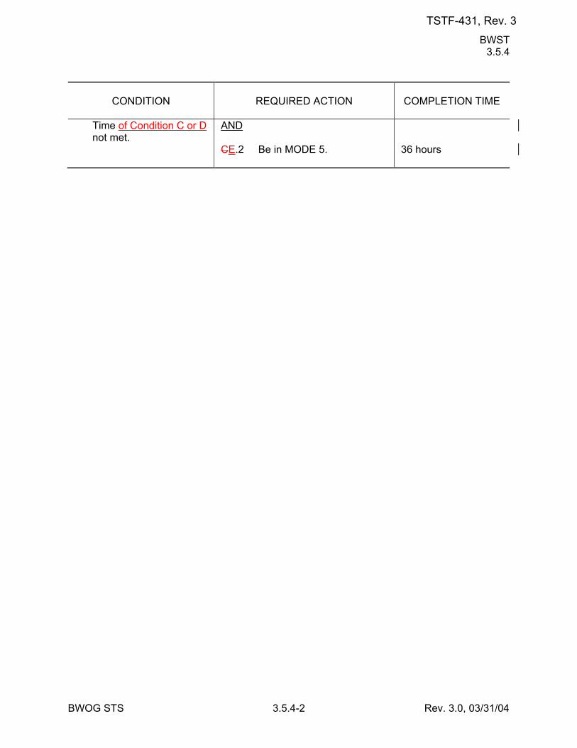
BWST 3.5.4
BWOG STS 3.5.4-2 Rev. 3.0, 03/31/04
CONDITION
REQUIRED ACTION
COMPLETION TIME
Time of Condition C or D not met.
AND CE.2 Be in MODE 5.
36 hours
TSTF-431, Rev. 3
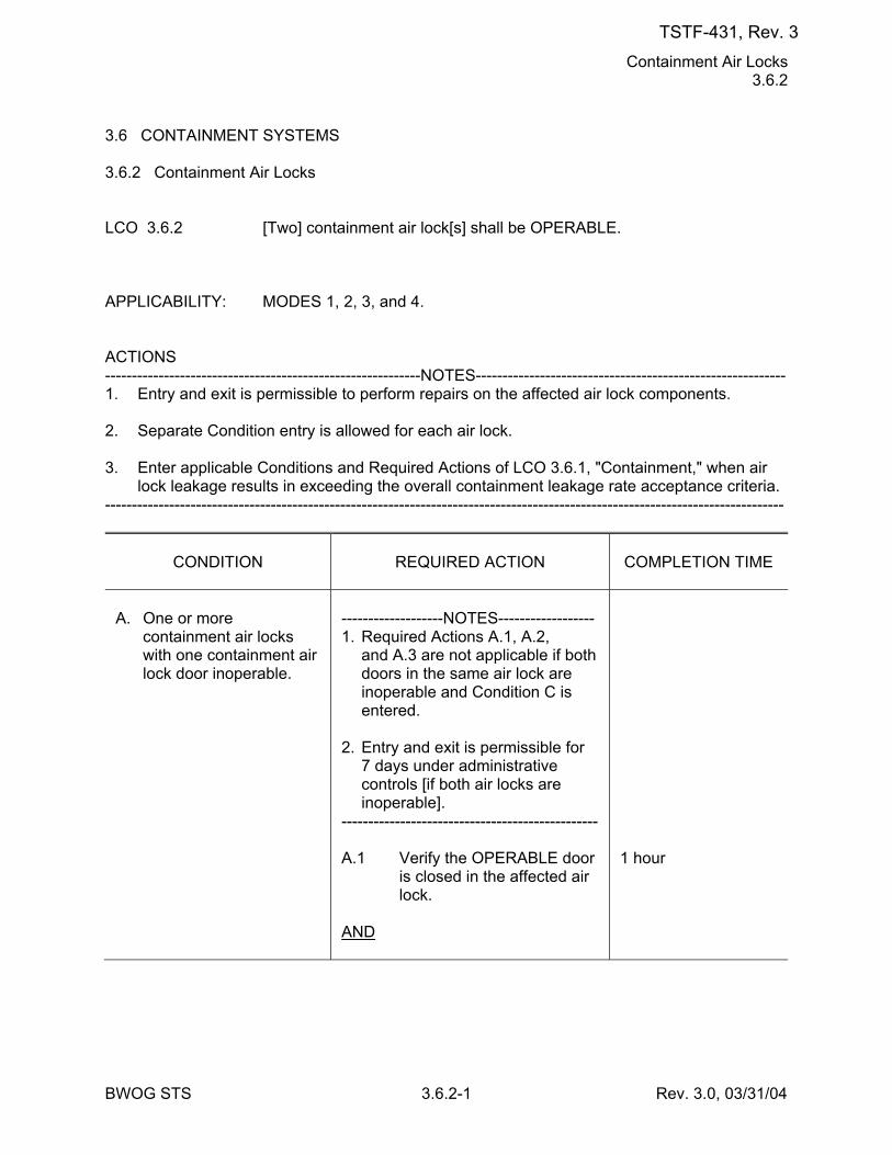
Containment Air Locks 3.6.2
BWOG STS 3.6.2-1 Rev. 3.0, 03/31/04
3.6 CONTAINMENT SYSTEMS 3.6.2 Containment Air Locks LCO 3.6.2 [Two] containment air lock[s] shall be OPERABLE. APPLICABILITY: MODES 1, 2, 3, and 4. ACTIONS -----------------------------------------------------------NOTES---------------------------------------------------------- 1. Entry and exit is permissible to perform repairs on the affected air lock components. 2. Separate Condition entry is allowed for each air lock. 3. Enter applicable Conditions and Required Actions of LCO 3.6.1, "Containment," when air
lock leakage results in exceeding the overall containment leakage rate acceptance criteria. -------------------------------------------------------------------------------------------------------------------------------
CONDITION
REQUIRED ACTION
COMPLETION TIME
A. One or more
containment air locks with one containment air lock door inoperable.
-------------------NOTES------------------ 1. Required Actions A.1, A.2,
and A.3 are not applicable if both doors in the same air lock are inoperable and Condition C is entered.
2. Entry and exit is permissible for
7 days under administrative controls [if both air locks are inoperable].
------------------------------------------------ A.1 Verify the OPERABLE door
is closed in the affected air lock.
AND
1 hour
TSTF-431, Rev. 3
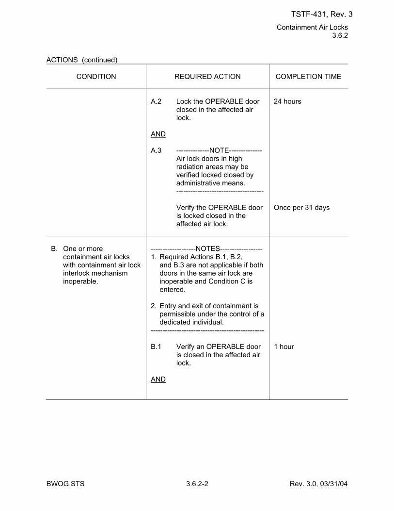
Containment Air Locks 3.6.2
BWOG STS 3.6.2-2 Rev. 3.0, 03/31/04
ACTIONS (continued)
CONDITION
REQUIRED ACTION
COMPLETION TIME
A.2 Lock the OPERABLE door
closed in the affected air lock.
AND A.3 --------------NOTE-------------- Air lock doors in high
radiation areas may be verified locked closed by administrative means.
------------------------------------- Verify the OPERABLE door
is locked closed in the affected air lock.
24 hours Once per 31 days
B. One or more
containment air locks with containment air lock interlock mechanism inoperable.
-------------------NOTES------------------ 1. Required Actions B.1, B.2,
and B.3 are not applicable if both doors in the same air lock are inoperable and Condition C is entered.
2. Entry and exit of containment is
permissible under the control of a dedicated individual.
------------------------------------------------ B.1 Verify an OPERABLE door
is closed in the affected air lock.
AND
1 hour
TSTF-431, Rev. 3
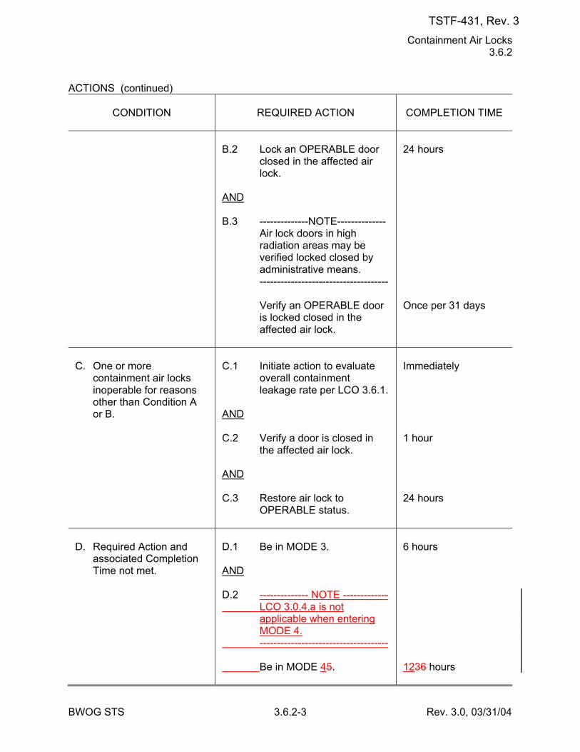
Containment Air Locks 3.6.2
BWOG STS 3.6.2-3 Rev. 3.0, 03/31/04
ACTIONS (continued)
CONDITION
REQUIRED ACTION
COMPLETION TIME
B.2 Lock an OPERABLE door
closed in the affected air lock.
AND B.3 --------------NOTE-------------- Air lock doors in high
radiation areas may be verified locked closed by administrative means.
------------------------------------- Verify an OPERABLE door
is locked closed in the affected air lock.
24 hours Once per 31 days
C. One or more
containment air locks inoperable for reasons other than Condition A or B.
C.1 Initiate action to evaluate
overall containment leakage rate per LCO 3.6.1.
AND C.2 Verify a door is closed in
the affected air lock. AND C.3 Restore air lock to
OPERABLE status.
Immediately 1 hour 24 hours
D. Required Action and
associated Completion Time not met.
D.1 Be in MODE 3. AND D.2 -------------- NOTE ------------- LCO 3.0.4.a is not
applicable when entering MODE 4.
------------------------------------- Be in MODE 45.
6 hours 1236 hours
TSTF-431, Rev. 3
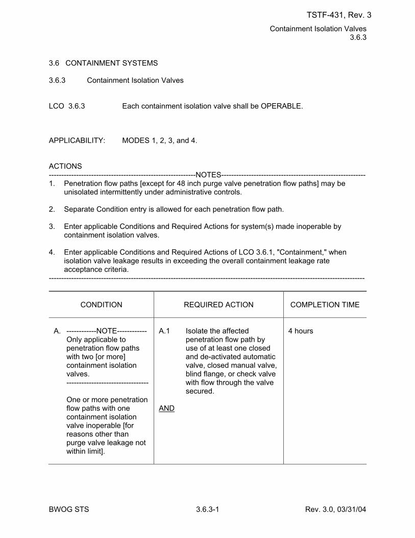
Containment Isolation Valves 3.6.3
BWOG STS 3.6.3-1 Rev. 3.0, 03/31/04
3.6 CONTAINMENT SYSTEMS 3.6.3 Containment Isolation Valves LCO 3.6.3 Each containment isolation valve shall be OPERABLE. APPLICABILITY: MODES 1, 2, 3, and 4. ACTIONS -----------------------------------------------------------NOTES---------------------------------------------------------- 1. Penetration flow paths [except for 48 inch purge valve penetration flow paths] may be
unisolated intermittently under administrative controls. 2. Separate Condition entry is allowed for each penetration flow path. 3. Enter applicable Conditions and Required Actions for system(s) made inoperable by
containment isolation valves. 4. Enter applicable Conditions and Required Actions of LCO 3.6.1, "Containment," when
isolation valve leakage results in exceeding the overall containment leakage rate acceptance criteria.
-------------------------------------------------------------------------------------------------------------------------------
CONDITION
REQUIRED ACTION
COMPLETION TIME
A. ------------NOTE------------ Only applicable to
penetration flow paths with two [or more] containment isolation valves.
--------------------------------- One or more penetration
flow paths with one containment isolation valve inoperable [for reasons other than purge valve leakage not within limit].
A.1 Isolate the affected
penetration flow path by use of at least one closed and de-activated automatic valve, closed manual valve, blind flange, or check valve with flow through the valve secured.
AND
4 hours
TSTF-431, Rev. 3
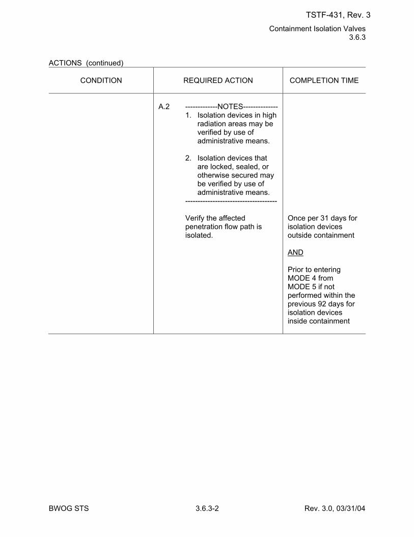
Containment Isolation Valves 3.6.3
BWOG STS 3.6.3-2 Rev. 3.0, 03/31/04
ACTIONS (continued)
CONDITION
REQUIRED ACTION
COMPLETION TIME
A.2 -------------NOTES-------------- 1. Isolation devices in high
radiation areas may be verified by use of administrative means.
2. Isolation devices that
are locked, sealed, or otherwise secured may be verified by use of administrative means.
------------------------------------- Verify the affected
penetration flow path is isolated.
Once per 31 days for isolation devices outside containment AND Prior to entering MODE 4 from MODE 5 if not performed within the previous 92 days for isolation devices inside containment
TSTF-431, Rev. 3
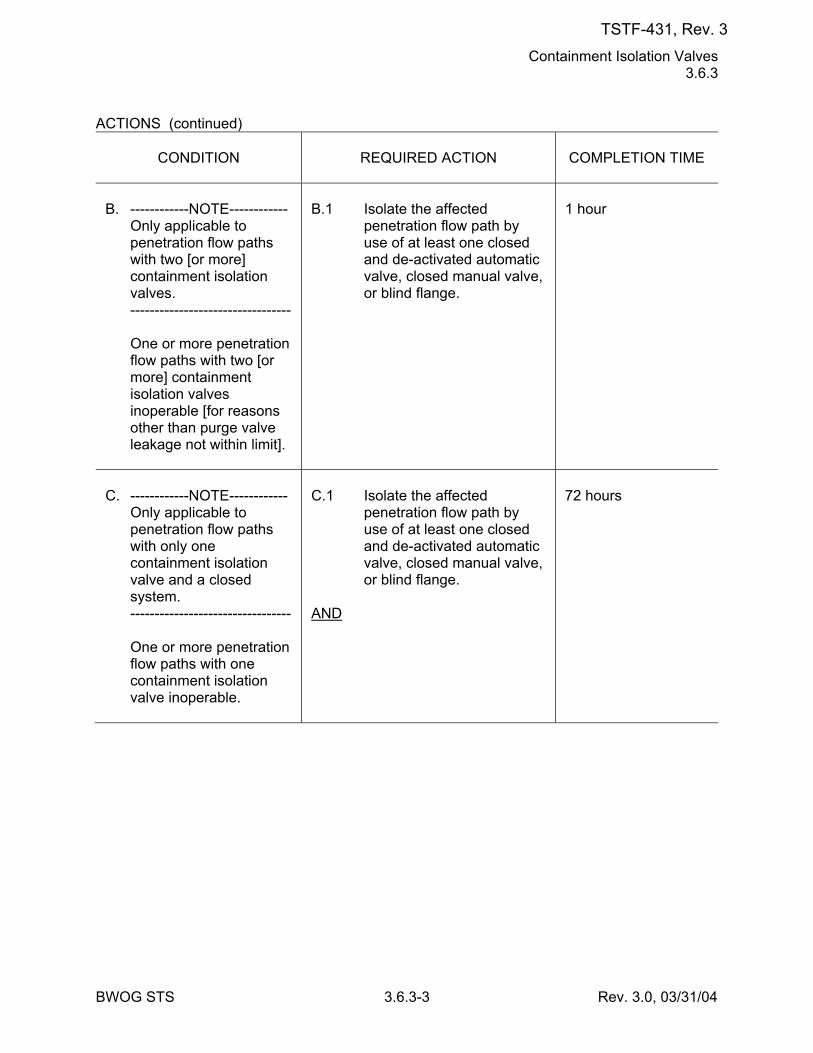
Containment Isolation Valves 3.6.3
BWOG STS 3.6.3-3 Rev. 3.0, 03/31/04
ACTIONS (continued)
CONDITION
REQUIRED ACTION
COMPLETION TIME
B. ------------NOTE------------ Only applicable to
penetration flow paths with two [or more] containment isolation valves.
--------------------------------- One or more penetration
flow paths with two [or more] containment isolation valves inoperable [for reasons other than purge valve leakage not within limit].
B.1 Isolate the affected
penetration flow path by use of at least one closed and de-activated automatic valve, closed manual valve, or blind flange.
1 hour
C. ------------NOTE------------ Only applicable to
penetration flow paths with only one containment isolation valve and a closed system.
--------------------------------- One or more penetration
flow paths with one containment isolation valve inoperable.
C.1 Isolate the affected
penetration flow path by use of at least one closed and de-activated automatic valve, closed manual valve, or blind flange.
AND
72 hours
TSTF-431, Rev. 3
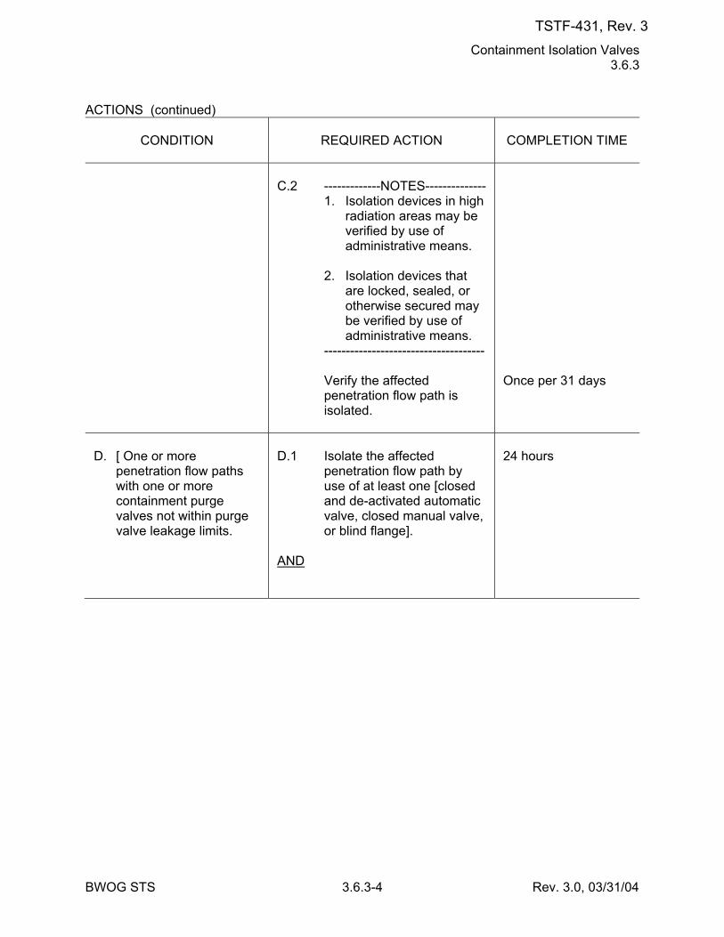
Containment Isolation Valves 3.6.3
BWOG STS 3.6.3-4 Rev. 3.0, 03/31/04
ACTIONS (continued)
CONDITION
REQUIRED ACTION
COMPLETION TIME
C.2 -------------NOTES-------------- 1. Isolation devices in high
radiation areas may be verified by use of administrative means.
2. Isolation devices that
are locked, sealed, or otherwise secured may be verified by use of administrative means.
------------------------------------- Verify the affected
penetration flow path is isolated.
Once per 31 days
D. [ One or more
penetration flow paths with one or more containment purge valves not within purge valve leakage limits.
D.1 Isolate the affected
penetration flow path by use of at least one [closed and de-activated automatic valve, closed manual valve, or blind flange].
AND
24 hours
TSTF-431, Rev. 3
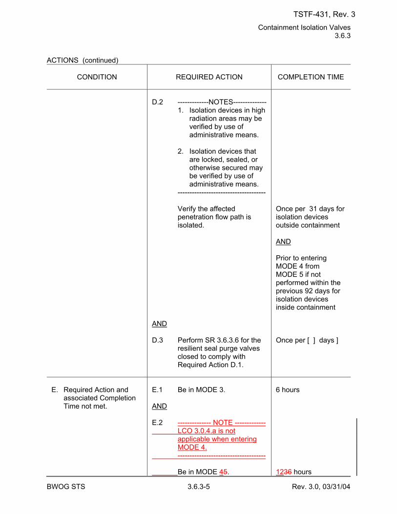
Containment Isolation Valves 3.6.3
BWOG STS 3.6.3-5 Rev. 3.0, 03/31/04
ACTIONS (continued)
CONDITION
REQUIRED ACTION
COMPLETION TIME
D.2 -------------NOTES-------------- 1. Isolation devices in high
radiation areas may be verified by use of administrative means.
2. Isolation devices that
are locked, sealed, or otherwise secured may be verified by use of administrative means.
------------------------------------- Verify the affected
penetration flow path is isolated.
AND D.3 Perform SR 3.6.3.6 for the
resilient seal purge valves closed to comply with Required Action D.1.
Once per 31 days for isolation devices outside containment AND Prior to entering MODE 4 from MODE 5 if not performed within the previous 92 days for isolation devices inside containment Once per [ ] days ]
E. Required Action and
associated Completion Time not met.
E.1 Be in MODE 3. AND E.2 -------------- NOTE ------------- LCO 3.0.4.a is not
applicable when entering MODE 4.
------------------------------------- Be in MODE 45.
6 hours 1236 hours
TSTF-431, Rev. 3
Containment Pressure 3.6.4
BWOG STS 3.6.4-1 Rev. 3.0, 03/31/04
3.6 CONTAINMENT SYSTEMS 3.6.4 Containment Pressure LCO 3.6.4 Containment pressure shall be ≥ [-2.0] psig and ≤ [+3.0] psig. APPLICABILITY: MODES 1, 2, 3, and 4. ACTIONS
CONDITION
REQUIRED ACTION
COMPLETION TIME
A. Containment pressure
not within limits.
A.1 Restore containment
pressure to within limits.
1 hour
B. Required Action and
associated Completion Time not met.
B.1 Be in MODE 3. AND B.2 -------------- NOTE ------------- LCO 3.0.4.a is not
applicable when entering MODE 4.
------------------------------------- Be in MODE 45.
6 hours 1236 hours
SURVEILLANCE REQUIREMENTS
SURVEILLANCE
FREQUENCY
SR 3.6.4.1 Verify containment pressure is within limits.
12 hours
TSTF-431, Rev. 3
Containment Air Temperature 3.6.5
BWOG STS 3.6.5-1 Rev. 3.0, 03/31/04
3.6 CONTAINMENT SYSTEMS 3.6.5 Containment Air Temperature LCO 3.6.5 Containment average air temperature shall be ≤ [130]°F. APPLICABILITY: MODES 1, 2, 3, and 4. ACTIONS
CONDITION
REQUIRED ACTION
COMPLETION TIME
A. Containment average air
temperature not within limit.
A.1 Restore containment
average air temperature to within limit.
8 hours
B. Required Action and
associated Completion Time not met.
B.1 Be in MODE 3. AND B.2 -------------- NOTE ------------- LCO 3.0.4.a is not
applicable when entering MODE 4.
------------------------------------- Be in MODE 45.
6 hours 1236 hours
SURVEILLANCE REQUIREMENTS
SURVEILLANCE
FREQUENCY
SR 3.6.5.1 Verify containment average air temperature is within
limit.
24 hours
TSTF-431, Rev. 3
Containment Spray and Cooling Systems 3.6.6
BWOG STS 3.6.6-1 Rev. 3.1, 12/01/05
3.6 CONTAINMENT SYSTEMS 3.6.6 Containment Spray and Cooling Systems LCO 3.6.6 Two containment spray trains and two containment cooling trains shall be
OPERABLE. APPLICABILITY: MODES 1, 2, 3, and 4. ACTIONS
CONDITION
REQUIRED ACTION
COMPLETION TIME
A. One containment spray
train inoperable.
A.1 Restore containment spray
train to OPERABLE status.
[7] days
B. Required Action and
associated Completion Time of Condition A not met.
B.1 Be in MODE 3. AND B.2 -------------- NOTE ------------- LCO 3.0.4.a is not
applicable when entering MODE 4.
------------------------------------- Be in MODE 45.
6 hours 6084 hours
C. One [required]
containment cooling train inoperable.
C.1 Restore [required]
containment cooling train to OPERABLE status.
7 days
D. One containment spray
train and one [required] containment cooling train inoperable.
D.1 Restore containment spray
train to OPERABLE status. OR D.2 Restore [required]
containment cooling train to OPERABLE status.
72 hours
TSTF-431, Rev. 3
Containment Spray and Cooling Systems 3.6.6
BWOG STS 3.6.6-2 Rev. 3.1, 12/01/05
ACTIONS (continued)
CONDITION
REQUIRED ACTION
COMPLETION TIME
E. Two [required]
containment cooling trains inoperable.
E.1 Restore one [required]
containment cooling train to OPERABLE status.
72 hours
F. Required Action and
associated Completion Time of Condition C or D not met.
F.1 Be in MODE 3. AND F.2 -------------- NOTE ------------- LCO 3.0.4.a is not
applicable when entering MODE 4.
------------------------------------- Be in MODE 45.
6 hours 1236 hours
G. Two containment spray
trains inoperable. OR Any combination of three
or more trains inoperable.
G.1 Enter LCO 3.0.3.
Immediately
SURVEILLANCE REQUIREMENTS
SURVEILLANCE
FREQUENCY
SR 3.6.6.1 Verify each containment spray manual, power
operated, and automatic valve in the flow path that is not locked, sealed, or otherwise secured in position is in the correct position.
31 days
SR 3.6.6.2 Operate each [required] containment cooling train
fan unit for ≥ 15 minutes.
31 days
TSTF-431, Rev. 3
CCW System 3.7.7
BWOG STS 3.7.7-1 Rev. 3.0, 03/31/04
3.7 PLANT SYSTEMS 3.7.7 Component Cooling Water (CCW) System LCO 3.7.7 Two CCW trains shall be OPERABLE. APPLICABILITY: MODES 1, 2, 3, and 4. ACTIONS
CONDITION
REQUIRED ACTION
COMPLETION TIME
A. One CCW train
inoperable.
A.1 -------------NOTES-------------- 1. Enter applicable
Conditions and Required Actions of LCO 3.8.1, "AC Sources - Operating," for emergency diesel generator made inoperable by CCW.
2. Enter applicable
Conditions and Required Actions of LCO 3.4.6, "RCS Loops - MODE 4," for decay heat removal made inoperable by CCW.
------------------------------------- Restore CCW train to
OPERABLE status.
72 hours
B. Required Action and
associated Completion Time of Condition A not met.
B.1 Be in MODE 3. AND B.2 -------------- NOTE ------------- LCO 3.0.4.a is not
applicable when entering MODE 4.
-------------------------------------
6 hours
TSTF-431, Rev. 3
CCW System 3.7.7
BWOG STS 3.7.7-2 Rev. 3.0, 03/31/04
CONDITION
REQUIRED ACTION
COMPLETION TIME
Be in MODE 45.
1236 hours
TSTF-431, Rev. 3
SWS 3.7.8
BWOG STS 3.7.8-1 Rev. 3.0, 03/31/04
3.7 PLANT SYSTEMS 3.7.8 Service Water System (SWS) LCO 3.7.8 Two SWS trains shall be OPERABLE. APPLICABILITY: MODES 1, 2, 3, and 4. ACTIONS
CONDITION
REQUIRED ACTION
COMPLETION TIME
A. One SWS train
inoperable.
A.1 -------------NOTES-------------- 1. [ Enter applicable
Conditions and Required Actions of LCO 3.8.1, "AC Sources - Operating," for emergency diesel generator made inoperable by SWS. ]
2. [ Enter Applicable
Conditions and Required Actions of LCO 3.4.6, "RCS Loops - MODE 4," for decay heat removal made inoperable by SWS. ]
------------------------------------- Restore SWS train to
OPERABLE status.
72 hours
B. Required Action and
associated Completion Time of Condition A not met.
B.1 Be in MODE 3. AND B.2 -------------- NOTE ------------- LCO 3.0.4.a is not
applicable when entering MODE 4.
------------------------------------- Be in MODE 45.
6 hours 1236 hours
TSTF-431, Rev. 3
UHS 3.7.9
BWOG STS 3.7.9-1 Rev. 3.0, 03/31/04
3.7 PLANT SYSTEMS 3.7.9 Ultimate Heat Sink (UHS) LCO 3.7.9 The UHS shall be OPERABLE. APPLICABILITY: MODES 1, 2, 3, and 4. ACTIONS
CONDITION
REQUIRED ACTION
COMPLETION TIME
A. [ One or more cooling
towers with one cooling tower fan inoperable.
A.1 Restore cooling tower
fan(s) to OPERABLE status.
7 days ]
B. Required Action and
associated Completion Time of Condition A not met.
B.1 Be in MODE 3. AND B.2 -------------- NOTE ------------- LCO 3.0.4.a is not
applicable when entering MODE 4.
------------------------------------- Be in MODE 4.
6 hours 12 hours
-----REVIEWER'S NOTE----- The [ ]°F is the maximum allowed UHS temperature value and is based on temperature limitations of the equipment that is relied upon for accident mitigation and safe shutdown of the unit. -------------------------------------- CB. [ Water temperature of
the UHS > [90]°F and ≤ [ ]°F.
CB.1 Verify water temperature of
the UHS is ≤ [90]°F averaged over the previous 24 hour period.
Once per hour]
TSTF-431, Rev. 3
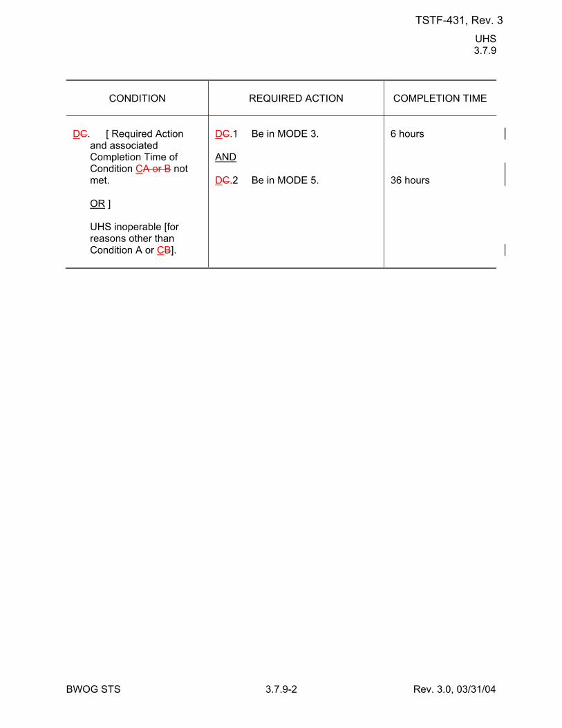
UHS 3.7.9
BWOG STS 3.7.9-2 Rev. 3.0, 03/31/04
CONDITION
REQUIRED ACTION
COMPLETION TIME
DC. [ Required Action
and associated Completion Time of Condition CA or B not met.
OR ] UHS inoperable [for
reasons other than Condition A or CB].
DC.1 Be in MODE 3. AND DC.2 Be in MODE 5.
6 hours 36 hours
TSTF-431, Rev. 3

CREVS 3.7.10
BWOG STS 3.7.10-1 Rev. 3.0, 03/31/04
3.7 PLANT SYSTEMS 3.7.10 Control Room Emergency Ventilation System (CREVS) LCO 3.7.10 Two CREVS trains shall be OPERABLE. ---------------------------------------------NOTE-------------------------------------------- The control room boundary may be opened intermittently under
administrative control. -------------------------------------------------------------------------------------------------- APPLICABILITY: MODES 1, 2, 3, and 4, [5, and 6], [During movement of [recently] irradiated fuel assemblies]. ACTIONS
CONDITION
REQUIRED ACTION
COMPLETION TIME
A. One CREVS train
inoperable.
A.1 Restore CREVS train to
OPERABLE status.
7 days
B. Two CREVS trains
inoperable due to inoperable control room boundary in MODE 1, 2, 3, or 4.
B.1 Restore control room
boundary to OPERABLE status.
24 hours
C. Required Action and
associated Completion Time of Condition A or B not met in MODE 1, 2, 3, or 4.
C.1 Be in MODE 3. AND C.2 -------------- NOTE ------------- LCO 3.0.4.a is not
applicable when entering MODE 4.
------------------------------------- Be in MODE 45.
6 hours 1236 hours
TSTF-431, Rev. 3
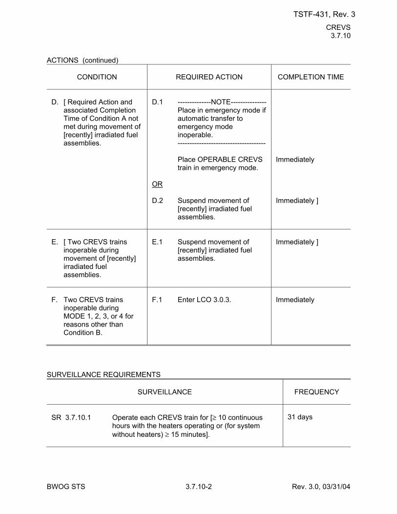
CREVS 3.7.10
BWOG STS 3.7.10-2 Rev. 3.0, 03/31/04
ACTIONS (continued)
CONDITION
REQUIRED ACTION
COMPLETION TIME
D. [ Required Action and
associated Completion Time of Condition A not met during movement of [recently] irradiated fuel assemblies.
D.1 --------------NOTE--------------- Place in emergency mode if
automatic transfer to emergency mode inoperable.
------------------------------------- Place OPERABLE CREVS
train in emergency mode. OR D.2 Suspend movement of
[recently] irradiated fuel assemblies.
Immediately Immediately ]
E. [ Two CREVS trains
inoperable during movement of [recently] irradiated fuel assemblies.
E.1 Suspend movement of
[recently] irradiated fuel assemblies.
Immediately ]
F. Two CREVS trains
inoperable during MODE 1, 2, 3, or 4 for reasons other than Condition B.
F.1 Enter LCO 3.0.3.
Immediately
SURVEILLANCE REQUIREMENTS
SURVEILLANCE
FREQUENCY
SR 3.7.10.1 Operate each CREVS train for [≥ 10 continuous
hours with the heaters operating or (for system without heaters) ≥ 15 minutes].
31 days
TSTF-431, Rev. 3
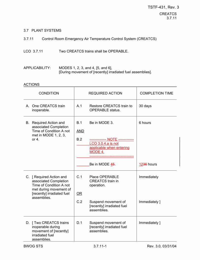
CREATCS 3.7.11
BWOG STS 3.7.11-1 Rev. 3.0, 03/31/04
3.7 PLANT SYSTEMS 3.7.11 Control Room Emergency Air Temperature Control System (CREATCS) LCO 3.7.11 Two CREATCS trains shall be OPERABLE. APPLICABILITY: MODES 1, 2, 3, and 4, [5, and 6], [During movement of [recently] irradiated fuel assemblies]. ACTIONS
CONDITION
REQUIRED ACTION
COMPLETION TIME
A. One CREATCS train
inoperable.
A.1 Restore CREATCS train to
OPERABLE status.
30 days
B. Required Action and
associated Completion Time of Condition A not met in MODE 1, 2, 3, or 4.
B.1 Be in MODE 3. AND B.2 -------------- NOTE ------------- LCO 3.0.4.a is not
applicable when entering MODE 4.
------------------------------------- Be in MODE 45.
6 hours 1236 hours
C. [ Required Action and
associated Completion Time of Condition A not met during movement of [recently] irradiated fuel assemblies.
C.1 Place OPERABLE
CREATCS train in operation.
OR C.2 Suspend movement of
[recently] irradiated fuel assemblies.
Immediately Immediately ]
D. [ Two CREATCS trains
inoperable during movement of [recently] irradiated fuel assemblies.
D.1 Suspend movement of
[recently] irradiated fuel assemblies.
Immediately ]
TSTF-431, Rev. 3
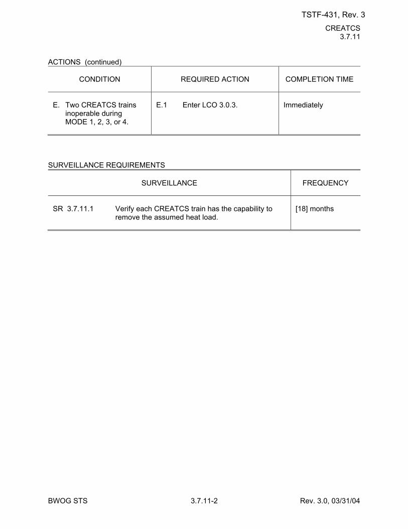
CREATCS 3.7.11
BWOG STS 3.7.11-2 Rev. 3.0, 03/31/04
ACTIONS (continued)
CONDITION
REQUIRED ACTION
COMPLETION TIME
E. Two CREATCS trains
inoperable during MODE 1, 2, 3, or 4.
E.1 Enter LCO 3.0.3.
Immediately
SURVEILLANCE REQUIREMENTS
SURVEILLANCE
FREQUENCY
SR 3.7.11.1 Verify each CREATCS train has the capability to
remove the assumed heat load.
[18] months
TSTF-431, Rev. 3
AC Sources - Operating 3.8.1
BWOG STS 3.8.1-1 Rev. 3.1, 12/01/05
3.8 ELECTRICAL POWER SYSTEMS 3.8.1 AC Sources - Operating LCO 3.8.1 The following AC electrical power sources shall be OPERABLE: a. Two qualified circuits between the offsite transmission network and
the onsite Class 1E AC Electrical Power Distribution System, b. Two diesel generators (DGs) each capable of supplying one train of
the onsite Class 1E AC Electrical Power Distribution System, and [ c. Automatic load sequencers for Train A and Train B. ] APPLICABILITY: MODES 1, 2, 3, and 4. ACTIONS -----------------------------------------------------------NOTE----------------------------------------------------------- LCO 3.0.4.b is not applicable to DGs. -------------------------------------------------------------------------------------------------------------------------------
CONDITION
REQUIRED ACTION
COMPLETION TIME
A. One [required] offsite
circuit inoperable.
A.1 Perform SR 3.8.1.1 for
OPERABLE [required] offsite circuit.
AND A.2 Declare required feature(s)
with no offsite power available inoperable when its redundant required feature(s) is inoperable.
AND
1 hour AND Once per 8 hours thereafter 24 hours from discovery of no offsite power to one train concurrent with inoperability of redundant required feature(s)
TSTF-431, Rev. 3
AC Sources - Operating 3.8.1
BWOG STS 3.8.1-2 Rev. 3.1, 12/01/05
ACTIONS (continued)
CONDITION
REQUIRED ACTION
COMPLETION TIME
A.3 Restore [required] offsite
circuit to OPERABLE status.
72 hours
B. One [required] DG
inoperable.
B.1 Perform SR 3.8.1.1 for
OPERABLE [required] offsite circuit(s).
AND B.2 Declare required feature(s)
supported by the inoperable DG inoperable when its redundant required feature(s) is inoperable.
AND B.3.1 Determine OPERABLE
DG(s) is not inoperable due to common cause failure.
OR B.3.2 Perform SR 3.8.1.2 for
OPERABLE DG(s). AND B.4 Restore [required] DG to
OPERABLE status.
1 hour AND Once per 8 hours thereafter 4 hours from discovery of Condition B concurrent with inoperability of redundant required feature(s) [24] hours [24] hours 72 hours
TSTF-431, Rev. 3
AC Sources - Operating 3.8.1
BWOG STS 3.8.1-3 Rev. 3.1, 12/01/05
ACTIONS (continued)
CONDITION
REQUIRED ACTION
COMPLETION TIME
C. Two [required] offsite
circuits inoperable.
C.1 Declare required feature(s)
inoperable when its redundant required feature(s) is inoperable.
AND C.2 Restore one [required]
offsite circuit to OPERABLE status.
12 hours from discovery of Condition C concurrent with inoperability of redundant required feature(s) 24 hours
D. One [required] offsite
circuit inoperable. AND One [required] DG
inoperable.
-------------------NOTE-------------------- Enter applicable Conditions and Required Actions of LCO 3.8.9, "Distribution Systems - Operating," when Condition D is entered with no AC power source to any train. ------------------------------------------------ D.1 Restore [required] offsite
circuit to OPERABLE status.
OR D.2 Restore [required] DG to
OPERABLE status.
12 hours 12 hours
E. Two [required] DGs
inoperable.
E.1 Restore one [required] DG
to OPERABLE status.
2 hours
TSTF-431, Rev. 3
AC Sources - Operating 3.8.1
BWOG STS 3.8.1-4 Rev. 3.1, 12/01/05
ACTIONS (continued)
CONDITION
REQUIRED ACTION
COMPLETION TIME
-----REVIEWER'S NOTE----- [ This Condition may be deleted if the unit design is such that any sequencer failure mode will only affect the ability of the associated DG to power its respective safety loads following a loss of offsite power independent of, or coincident with, a Design Basis Event. -------------------------------------- F. One [required]
[automatic load sequencer] inoperable.
F.1 Restore [required]
[automatic load sequencer] to OPERABLE status.
[12] hours ]
G. Required Action and
Associated Completion Time of Condition A, B, C, D, E, or [F] not met.
G.1 Be in MODE 3. AND G.2 -------------- NOTE ------------- LCO 3.0.4.a is not
applicable when entering MODE 4.
------------------------------------- Be in MODE 45.
6 hours 1236 hours
H. Three or more [required]
AC sources inoperable.
H.1 Enter LCO 3.0.3.
Immediately
SURVEILLANCE REQUIREMENTS
SURVEILLANCE
FREQUENCY
SR 3.8.1.1 Verify correct breaker alignment and indicated
power availability for each [required] offsite circuit.
7 days
TSTF-431, Rev. 3
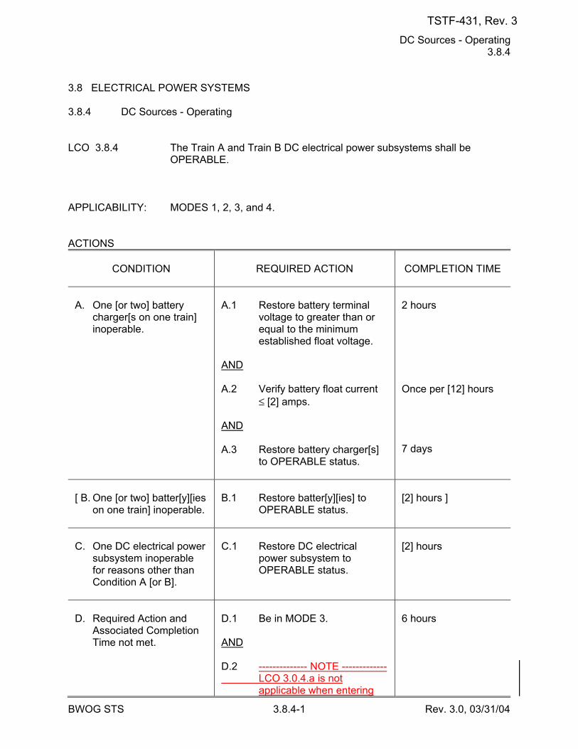
DC Sources - Operating 3.8.4
BWOG STS 3.8.4-1 Rev. 3.0, 03/31/04
3.8 ELECTRICAL POWER SYSTEMS 3.8.4 DC Sources - Operating LCO 3.8.4 The Train A and Train B DC electrical power subsystems shall be
OPERABLE. APPLICABILITY: MODES 1, 2, 3, and 4. ACTIONS
CONDITION
REQUIRED ACTION
COMPLETION TIME
A. One [or two] battery
charger[s on one train] inoperable.
A.1 Restore battery terminal
voltage to greater than or equal to the minimum established float voltage.
AND A.2 Verify battery float current
≤ [2] amps. AND A.3 Restore battery charger[s]
to OPERABLE status.
2 hours Once per [12] hours 7 days
[ B. One [or two] batter[y][ies
on one train] inoperable.
B.1 Restore batter[y][ies] to
OPERABLE status.
[2] hours ]
C. One DC electrical power
subsystem inoperable for reasons other than Condition A [or B].
C.1 Restore DC electrical
power subsystem to OPERABLE status.
[2] hours
D. Required Action and
Associated Completion Time not met.
D.1 Be in MODE 3. AND D.2 -------------- NOTE ------------- LCO 3.0.4.a is not
applicable when entering
6 hours
TSTF-431, Rev. 3

DC Sources - Operating 3.8.4
BWOG STS 3.8.4-2 Rev. 3.0, 03/31/04
CONDITION
REQUIRED ACTION
COMPLETION TIME
MODE 4.
------------------------------------- Be in MODE 45.
1236 hours
TSTF-431, Rev. 3
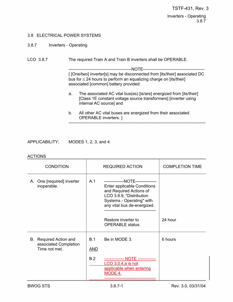
Inverters - Operating 3.8.7
BWOG STS 3.8.7-1 Rev. 3.0, 03/31/04
3.8 ELECTRICAL POWER SYSTEMS 3.8.7 Inverters - Operating LCO 3.8.7 The required Train A and Train B inverters shall be OPERABLE. ---------------------------------------------NOTE-------------------------------------------- [ [One/two] inverter[s] may be disconnected from [its/their] associated DC
bus for ≤ 24 hours to perform an equalizing charge on [its/their] associated [common] battery provided:
a. The associated AC vital bus(es) [is/are] energized from [its/their]
[Class 1E constant voltage source transformers] [inverter using internal AC source] and
b. All other AC vital buses are energized from their associated
OPERABLE inverters. ] -------------------------------------------------------------------------------------------------- APPLICABILITY: MODES 1, 2, 3, and 4. ACTIONS
CONDITION
REQUIRED ACTION
COMPLETION TIME
A. One [required] inverter
inoperable.
A.1 --------------NOTE--------------- Enter applicable Conditions
and Required Actions of LCO 3.8.9, "Distribution Systems - Operating" with any vital bus de-energized.
------------------------------------- Restore inverter to
OPERABLE status.
24 hour
B. Required Action and
associated Completion Time not met.
B.1 Be in MODE 3. AND B.2 -------------- NOTE ------------- LCO 3.0.4.a is not
applicable when entering MODE 4.
-------------------------------------
6 hours
TSTF-431, Rev. 3
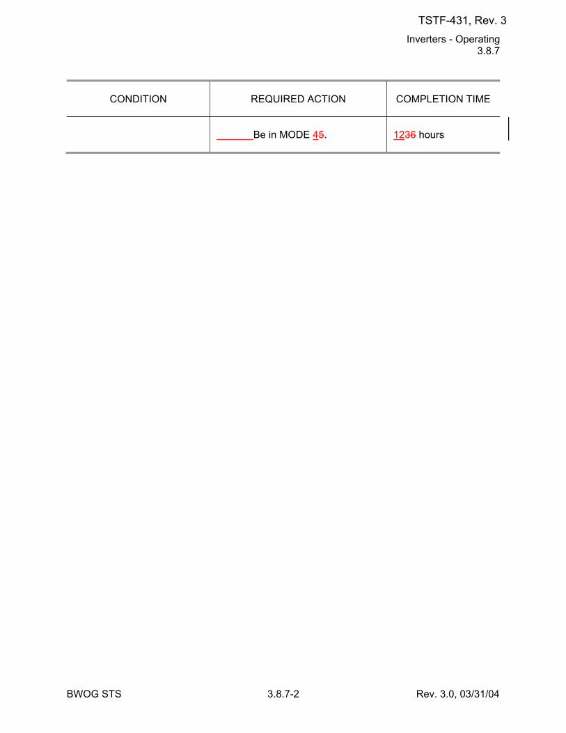
Inverters - Operating 3.8.7
BWOG STS 3.8.7-2 Rev. 3.0, 03/31/04
CONDITION
REQUIRED ACTION
COMPLETION TIME
Be in MODE 45.
1236 hours
TSTF-431, Rev. 3
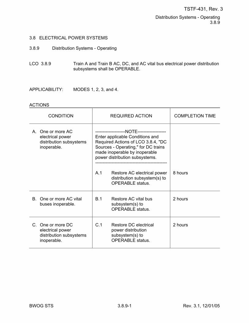
Distribution Systems - Operating 3.8.9
BWOG STS 3.8.9-1 Rev. 3.1, 12/01/05
3.8 ELECTRICAL POWER SYSTEMS 3.8.9 Distribution Systems - Operating LCO 3.8.9 Train A and Train B AC, DC, and AC vital bus electrical power distribution
subsystems shall be OPERABLE. APPLICABILITY: MODES 1, 2, 3, and 4. ACTIONS
CONDITION
REQUIRED ACTION
COMPLETION TIME
A. One or more AC
electrical power distribution subsystems inoperable.
--------------------NOTE------------------- Enter applicable Conditions and Required Actions of LCO 3.8.4, "DC Sources - Operating," for DC trains made inoperable by inoperable power distribution subsystems. ------------------------------------------------ A.1 Restore AC electrical power
distribution subsystem(s) to OPERABLE status.
8 hours
B. One or more AC vital
buses inoperable.
B.1 Restore AC vital bus
subsystem(s) to OPERABLE status.
2 hours
C. One or more DC
electrical power distribution subsystems inoperable.
C.1 Restore DC electrical
power distribution subsystem(s) to OPERABLE status.
2 hours
TSTF-431, Rev. 3
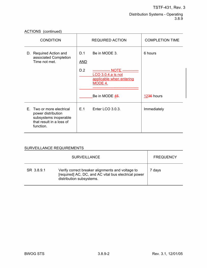
Distribution Systems - Operating 3.8.9
BWOG STS 3.8.9-2 Rev. 3.1, 12/01/05
ACTIONS (continued)
CONDITION
REQUIRED ACTION
COMPLETION TIME
D. Required Action and
associated Completion Time not met.
D.1 Be in MODE 3. AND D.2 -------------- NOTE ------------- LCO 3.0.4.a is not
applicable when entering MODE 4.
------------------------------------- Be in MODE 45.
6 hours 1236 hours
E. Two or more electrical
power distribution subsystems inoperable that result in a loss of function.
E.1 Enter LCO 3.0.3.
Immediately
SURVEILLANCE REQUIREMENTS
SURVEILLANCE
FREQUENCY
SR 3.8.9.1 Verify correct breaker alignments and voltage to
[required] AC, DC, and AC vital bus electrical power distribution subsystems.
7 days
TSTF-431, Rev. 3
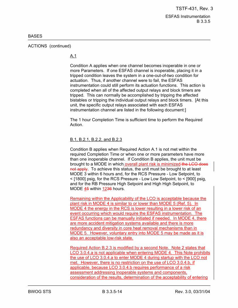
ESFAS Instrumentation B 3.3.5
BWOG STS B 3.3.5-14 Rev. 3.0, 03/31/04
BASES ACTIONS (continued)
A.1 Condition A applies when one channel becomes inoperable in one or more Parameters. If one ESFAS channel is inoperable, placing it in a tripped condition leaves the system in a one-out-of-two condition for actuation. Thus, if another channel were to fail, the ESFAS instrumentation could still perform its actuation functions. This action is completed when all of the affected output relays and block timers are tripped. This can normally be accomplished by tripping the affected bistables or tripping the individual output relays and block timers. [At this unit, the specific output relays associated with each ESFAS instrumentation channel are listed in the following document:] The 1 hour Completion Time is sufficient time to perform the Required Action. B.1, B.2.1, B.2.2, and B.2.3 Condition B applies when Required Action A.1 is not met within the required Completion Time or when one or more parameters have more than one inoperable channel. If Condition B applies, the unit must be brought to a MODE in which overall plant risk is minimized the LCO does not apply. To achieve this status, the unit must be brought to at least MODE 3 within 6 hours and, for the RCS Pressure - Low Setpoint, to < [1800] psig, for the RCS Pressure - Low Low Setpoint, to < [900] psig, and for the RB Pressure High Setpoint and High High Setpoint, to MODE 45 within 1236 hours. Remaining within the Applicability of the LCO is acceptable because the plant risk in MODE 4 is similar to or lower than MODE 5 (Ref. 5). In MODE 4 the energy in the RCS is lower resulting in a lower risk of an event occurring which would require the ESFAS instrumentation. The ESFAS functions can be manually initiated if needed. In MODE 4, there are more accident mitigation systems available and there is more redundancy and diversity in core heat removal mechanisms than in MODE 5. However, voluntary entry into MODE 5 may be made as it is also an acceptable low-risk state. Required Action B.2.3 is modified by a second Note. Note 2 states that LCO 3.0.4.a is not applicable when entering MODE 4. This Note prohibits the use of LCO 3.0.4.a to enter MODE 4 during startup with the LCO not met. However, there is no restriction on the use of LCO 3.0.4.b, if applicable, because LCO 3.0.4.b requires performance of a risk assessment addressing inoperable systems and components, consideration of the results, determination of the acceptability of entering
TSTF-431, Rev. 3
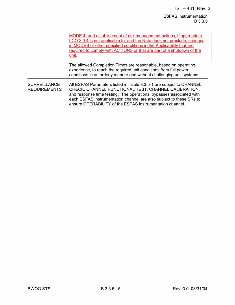
ESFAS Instrumentation B 3.3.5
BWOG STS B 3.3.5-15 Rev. 3.0, 03/31/04
MODE 4, and establishment of risk management actions, if appropriate. LCO 3.0.4 is not applicable to, and the Note does not preclude, changes in MODES or other specified conditions in the Applicability that are required to comply with ACTIONS or that are part of a shutdown of the unit. The allowed Completion Times are reasonable, based on operating experience, to reach the required unit conditions from full power conditions in an orderly manner and without challenging unit systems.
SURVEILLANCE All ESFAS Parameters listed in Table 3.3.5-1 are subject to CHANNEL REQUIREMENTS CHECK, CHANNEL FUNCTIONAL TEST, CHANNEL CALIBRATION,
and response time testing. The operational bypasses associated with each ESFAS instrumentation channel are also subject to these SRs to ensure OPERABILITY of the ESFAS instrumentation channel.
TSTF-431, Rev. 3
ESFAS Instrumentation B 3.3.5
BWOG STS B 3.3.5-18 Rev. 3.0, 03/31/04
BASES SURVEILLANCE REQUIREMENTS (continued)
actuation setpoint value at the sensor to the point at which the end device is actuated. Thus, this SR encompasses the automatic actuation logic components covered by LCO 3.3.7 and the operation of the mechanical ESF components. Response time tests are conducted on an [18] month STAGGERED TEST BASIS. Testing of the final actuation devices, which make up the bulk of the response time, is included in the testing of each channel. Therefore, staggered testing results in response time verification of these devices every [18] months. The 18 month test Frequency is based on unit operating experience, which shows that random failures of instrumentation components causing serious response time degradation but not channel failure are infrequent occurrences.
REFERENCES 1. FSAR, Chapter [7]. 2. 10 CFR 50.49. 3. [Unit Specific Setpoint Methodology.] 4. FSAR, Chapter [14]. 5. BAW-2441-A, Revision 2, Risk Informed Justification for LCO End-
State Changes, September 2006.
TSTF-431, Rev. 3
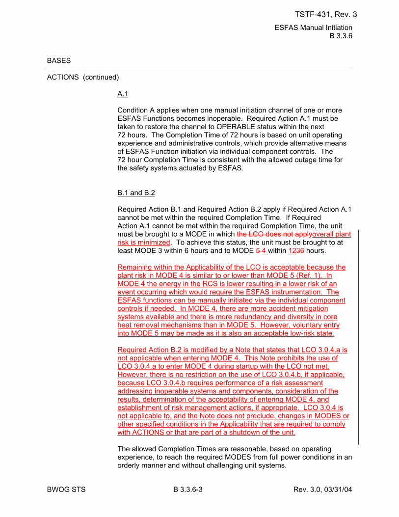
ESFAS Manual Initiation B 3.3.6
BWOG STS B 3.3.6-3 Rev. 3.0, 03/31/04
BASES ACTIONS (continued)
A.1 Condition A applies when one manual initiation channel of one or more ESFAS Functions becomes inoperable. Required Action A.1 must be taken to restore the channel to OPERABLE status within the next 72 hours. The Completion Time of 72 hours is based on unit operating experience and administrative controls, which provide alternative means of ESFAS Function initiation via individual component controls. The 72 hour Completion Time is consistent with the allowed outage time for the safety systems actuated by ESFAS. B.1 and B.2 Required Action B.1 and Required Action B.2 apply if Required Action A.1 cannot be met within the required Completion Time. If Required Action A.1 cannot be met within the required Completion Time, the unit must be brought to a MODE in which the LCO does not applyoverall plant risk is minimized. To achieve this status, the unit must be brought to at least MODE 3 within 6 hours and to MODE 5 4 within 1236 hours. Remaining within the Applicability of the LCO is acceptable because the plant risk in MODE 4 is similar to or lower than MODE 5 (Ref. 1). In MODE 4 the energy in the RCS is lower resulting in a lower risk of an event occurring which would require the ESFAS instrumentation. The ESFAS functions can be manually initiated via the individual component controls if needed. In MODE 4, there are more accident mitigation systems available and there is more redundancy and diversity in core heat removal mechanisms than in MODE 5. However, voluntary entry into MODE 5 may be made as it is also an acceptable low-risk state. Required Action B.2 is modified by a Note that states that LCO 3.0.4.a is not applicable when entering MODE 4. This Note prohibits the use of LCO 3.0.4.a to enter MODE 4 during startup with the LCO not met. However, there is no restriction on the use of LCO 3.0.4.b, if applicable, because LCO 3.0.4.b requires performance of a risk assessment addressing inoperable systems and components, consideration of the results, determination of the acceptability of entering MODE 4, and establishment of risk management actions, if appropriate. LCO 3.0.4 is not applicable to, and the Note does not preclude, changes in MODES or other specified conditions in the Applicability that are required to comply with ACTIONS or that are part of a shutdown of the unit. The allowed Completion Times are reasonable, based on operating experience, to reach the required MODES from full power conditions in an orderly manner and without challenging unit systems.
TSTF-431, Rev. 3
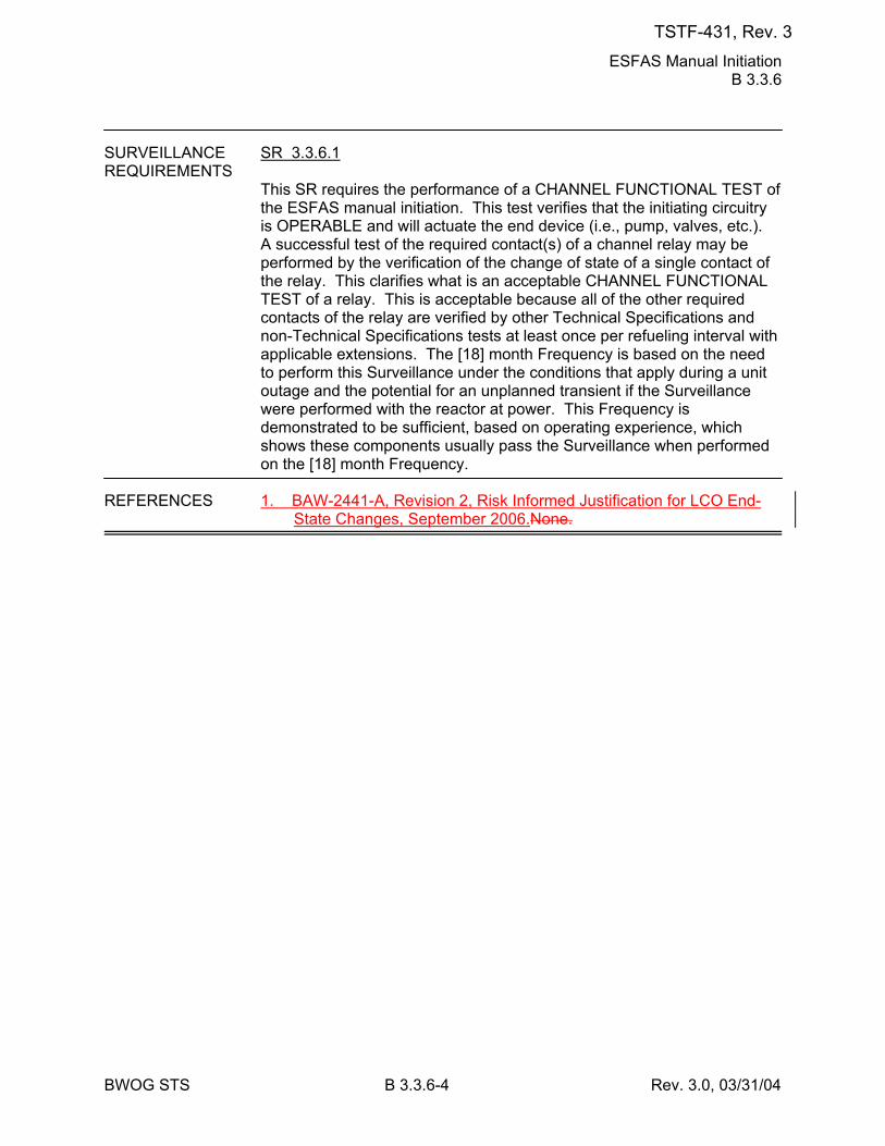
ESFAS Manual Initiation B 3.3.6
BWOG STS B 3.3.6-4 Rev. 3.0, 03/31/04
SURVEILLANCE SR 3.3.6.1 REQUIREMENTS
This SR requires the performance of a CHANNEL FUNCTIONAL TEST of the ESFAS manual initiation. This test verifies that the initiating circuitry is OPERABLE and will actuate the end device (i.e., pump, valves, etc.). A successful test of the required contact(s) of a channel relay may be performed by the verification of the change of state of a single contact of the relay. This clarifies what is an acceptable CHANNEL FUNCTIONAL TEST of a relay. This is acceptable because all of the other required contacts of the relay are verified by other Technical Specifications and non-Technical Specifications tests at least once per refueling interval with applicable extensions. The [18] month Frequency is based on the need to perform this Surveillance under the conditions that apply during a unit outage and the potential for an unplanned transient if the Surveillance were performed with the reactor at power. This Frequency is demonstrated to be sufficient, based on operating experience, which shows these components usually pass the Surveillance when performed on the [18] month Frequency.
REFERENCES 1. BAW-2441-A, Revision 2, Risk Informed Justification for LCO End-
State Changes, September 2006.None.
TSTF-431, Rev. 3
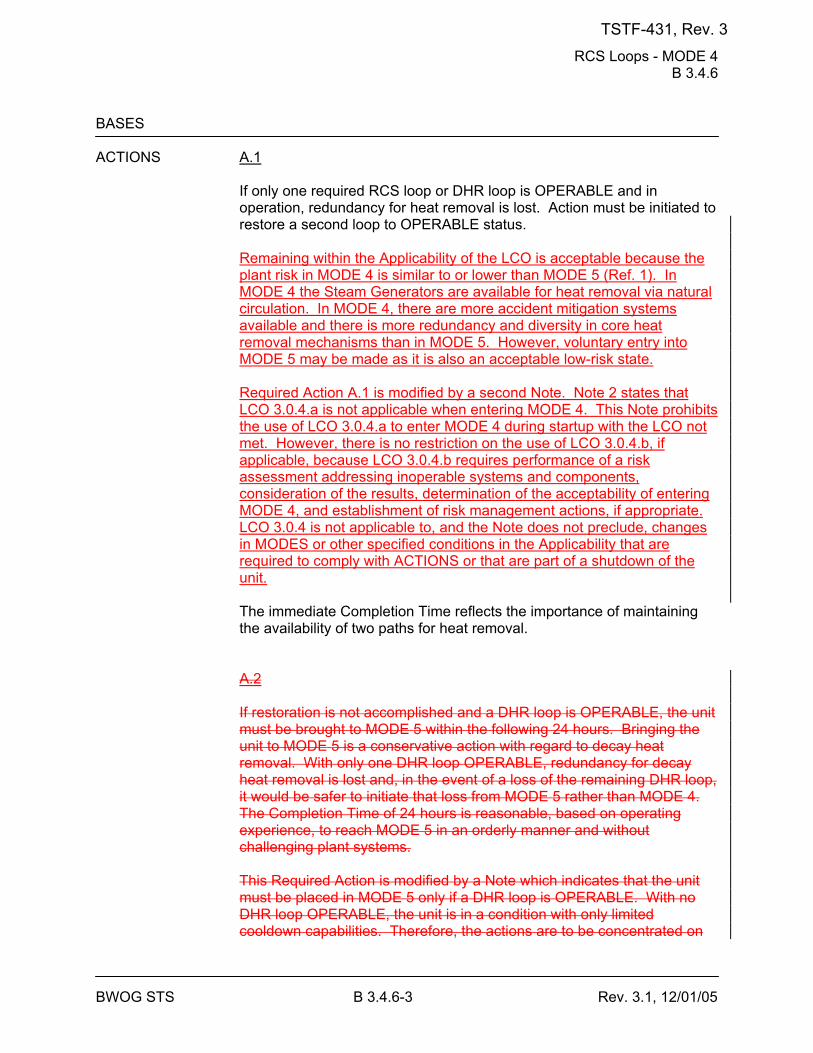
RCS Loops - MODE 4 B 3.4.6
BWOG STS B 3.4.6-3 Rev. 3.1, 12/01/05
BASES ACTIONS A.1
If only one required RCS loop or DHR loop is OPERABLE and in operation, redundancy for heat removal is lost. Action must be initiated to restore a second loop to OPERABLE status. Remaining within the Applicability of the LCO is acceptable because the plant risk in MODE 4 is similar to or lower than MODE 5 (Ref. 1). In MODE 4 the Steam Generators are available for heat removal via natural circulation. In MODE 4, there are more accident mitigation systems available and there is more redundancy and diversity in core heat removal mechanisms than in MODE 5. However, voluntary entry into MODE 5 may be made as it is also an acceptable low-risk state. Required Action A.1 is modified by a second Note. Note 2 states that LCO 3.0.4.a is not applicable when entering MODE 4. This Note prohibits the use of LCO 3.0.4.a to enter MODE 4 during startup with the LCO not met. However, there is no restriction on the use of LCO 3.0.4.b, if applicable, because LCO 3.0.4.b requires performance of a risk assessment addressing inoperable systems and components, consideration of the results, determination of the acceptability of entering MODE 4, and establishment of risk management actions, if appropriate. LCO 3.0.4 is not applicable to, and the Note does not preclude, changes in MODES or other specified conditions in the Applicability that are required to comply with ACTIONS or that are part of a shutdown of the unit. The immediate Completion Time reflects the importance of maintaining the availability of two paths for heat removal. A.2 If restoration is not accomplished and a DHR loop is OPERABLE, the unit must be brought to MODE 5 within the following 24 hours. Bringing the unit to MODE 5 is a conservative action with regard to decay heat removal. With only one DHR loop OPERABLE, redundancy for decay heat removal is lost and, in the event of a loss of the remaining DHR loop, it would be safer to initiate that loss from MODE 5 rather than MODE 4. The Completion Time of 24 hours is reasonable, based on operating experience, to reach MODE 5 in an orderly manner and without challenging plant systems. This Required Action is modified by a Note which indicates that the unit must be placed in MODE 5 only if a DHR loop is OPERABLE. With no DHR loop OPERABLE, the unit is in a condition with only limited cooldown capabilities. Therefore, the actions are to be concentrated on
TSTF-431, Rev. 3
RCS Loops - MODE 4 B 3.4.6
BWOG STS B 3.4.6-4 Rev. 3.1, 12/01/05
the restoration of a DHR loop, rather than a cooldown of extended duration. B.1 and B.2 If two required RCS or DHR loops are inoperable or a required loop is not in operation, except during conditions permitted by the Note in the LCO section, all operations involving introduction of coolant into the RCS with boron concentration less than required to meet the minimum SDM of LCO 3.1.1 must be suspended and action to restore one RCS or DHR loop to OPERABLE status and operation must be initiated. The required margin to criticality must not be reduced in this type of operation. Suspending the introduction of coolant, into the RCS, with boron concentration less than required to meet the minimum SDM of LCO 3.1.1 is required to ensure continued safe operation. With coolant added without forced circulation, unmixed coolant could be introduced to the core, however, coolant added with boron concentration meeting the minimum SDM maintains acceptable margin to subcritical operations. The immediate Completion Times reflect the importance of maintaining operation for decay heat removal. The action to restore must continue until one loop is restored to operation.
TSTF-431, Rev. 3
RCS Loops - MODE 4 B 3.4.6
BWOG STS B 3.4.6-5 Rev. 3.1, 12/01/05
BASES SURVEILLANCE SR 3.4.6.1 REQUIREMENTS
This Surveillance requires verification every 12 hours of the required DHR or RCS loop in operation to ensure forced flow is providing decay heat removal. Verification includes flow rate, temperature, or pump status monitoring. The 12 hour interval has been shown by operating practice to be sufficient to regularly assess RCS loop status. In addition, control room indication and alarms will normally indicate loop status. SR 3.4.6.2 Verification that each required pump is OPERABLE ensures that an additional RCS or DHR loop can be placed in operation if needed to maintain decay heat removal and reactor coolant circulation. Verification is performed by verifying proper breaker alignment and power available to each required pump. Alternatively, verification that a pump is in operation also verifies proper breaker alignment and power availability. The Frequency of 7 days is considered reasonable in view of other administrative controls and has been shown to be acceptable by operating experience. This SR is modified by a Note that states the SR is not required to be performed until 24 hours after a required pump is not in operation.
REFERENCES 1. BAW-2441-A, Revision 2, Risk Informed Justification for LCO End-
State Changes, September 2006.None.
TSTF-431, Rev. 3
RCS Leakage Detection Instrumentation B 3.4.15
BWOG STS B 3.4.15-4 Rev. 3.0, 03/31/04
BASES ACTIONS (continued)
B.1.1, B.1.2, and B.2 With required gaseous or particulate containment atmosphere radioactivity monitoring instrumentation channels inoperable, alternative action is required. Either grab samples of the containment atmosphere must be taken and analyzed or water inventory balances, in accordance with SR 3.4.13.1, must be performed to provide alternate periodic information. With a sample obtained and analyzed or a water inventory balance performed every 24 hours, the reactor may be operated for up to 30 days to allow restoration of at least one of the radioactivity monitors. The 24 hour interval provides periodic information that is adequate to detect leakage. A Note is added allowing that SR 3.4.13.1 is not required to be performed until 12 hours after establishing steady state operation (stable temperature, power level, pressurizer and makeup tank levels, makeup and letdown, and [RCP seal injection and return flows]). The 12 hour allowance provides sufficient time to collect and process all necessary data after stable plant conditions are established. The 30 day Completion Time recognizes at least one other form of leak detection is available. C.1 and C.2 If a Required Action of Condition A or B cannot be met within the required Completion Time, the unit must be brought to a MODE in which the LCO does not applyoverall plant risk is minimized. To achieve this status, the unit must be brought to at least MODE 3 within 6 hours and to MODE 45 within 1236 hours. Remaining within the Applicability of the LCO is acceptable because the plant risk in MODE 4 is similar to or lower than MODE 5 (Ref. 4). In MODE 4 the RCS pressure is lower and the risk of significant RCS leakage is reduced. In MODE 4, there are more accident mitigation systems available and there is more redundancy and diversity in core heat removal mechanisms than in MODE 5. However, voluntary entry into MODE 5 may be made as it is also an acceptable low-risk state. Required Action C.2 is modified by a second Note. Note 2 states that LCO 3.0.4.a is not applicable when entering MODE 4. This Note prohibits the use of LCO 3.0.4.a to enter MODE 4 during startup with the LCO not met. However, there is no restriction on the use of LCO 3.0.4.b, if applicable, because LCO 3.0.4.b requires performance of a risk assessment addressing inoperable systems and components, consideration of the results, determination of the acceptability of entering MODE 4, and establishment of risk management actions, if appropriate.
TSTF-431, Rev. 3
RCS Leakage Detection Instrumentation B 3.4.15
BWOG STS B 3.4.15-5 Rev. 3.0, 03/31/04
LCO 3.0.4 is not applicable to, and the Note does not preclude, changes in MODES or other specified conditions in the Applicability that are required to comply with ACTIONS or that are part of a shutdown of the unit. The allowed Completion Times are reasonable, based on operating experience, to reach the required plant conditions from full power conditions in an orderly manner and without challenging plant systems. D.1 With both required monitors inoperable, no automatic means of monitoring leakage are available, and immediate plant shutdown in accordance with LCO 3.0.3 is required.
TSTF-431, Rev. 3
RCS Leakage Detection Instrumentation B 3.4.15
BWOG STS B 3.4.15-6 Rev. 3.0, 03/31/04
BASES SURVEILLANCE SR 3.4.15.1 REQUIREMENTS
SR 3.4.15.1 requires the performance of a CHANNEL CHECK of the required containment atmosphere radioactivity monitor. The check gives reasonable confidence that each channel is operating properly. The Frequency of 12 hours is based on instrument reliability and is reasonable for detecting off normal conditions. SR 3.4.15.2 SR 3.4.15.2 requires the performance of a CHANNEL FUNCTIONAL TEST of the required containment atmosphere radioactivity monitor. A successful test of the required contact(s) of a channel relay may be performed by the verification of the change of state of a single contact of the relay. This clarifies what is an acceptable CHANNEL FUNCTIONAL TEST of a relay. This is acceptable because all of the other required contacts of the relay are verified by other Technical Specifications and non-Technical Specifications tests at least once per refueling interval with applicable extensions. The test ensures that the monitor can perform its function in the desired manner. The test verifies the alarm setpoint and relative accuracy of the instrument string. The Frequency of 92 days considers instrument reliability, and operating experience has shown it proper for detecting degradation. SR 3.4.15.3 and SR 3.4.15.4 These SRs require the performance of a CHANNEL CALIBRATION for each of the required RCS leakage detection instrumentation channels. The calibration verifies the accuracy of the instrument string, including the instruments located inside containment. The Frequency of [18] months is a typical refueling cycle and considers channel reliability. Again, operating experience has proven this Frequency is acceptable.
REFERENCES 1. 10 CFR 50, Appendix A, Section IV, GDC 30. 2. Regulatory Guide 1.45. 3. FSAR, Section [ ] . 4. BAW-2441-A, Revision 2, Risk Informed Justification for LCO End-
State Changes, September 2006.
TSTF-431, Rev. 3
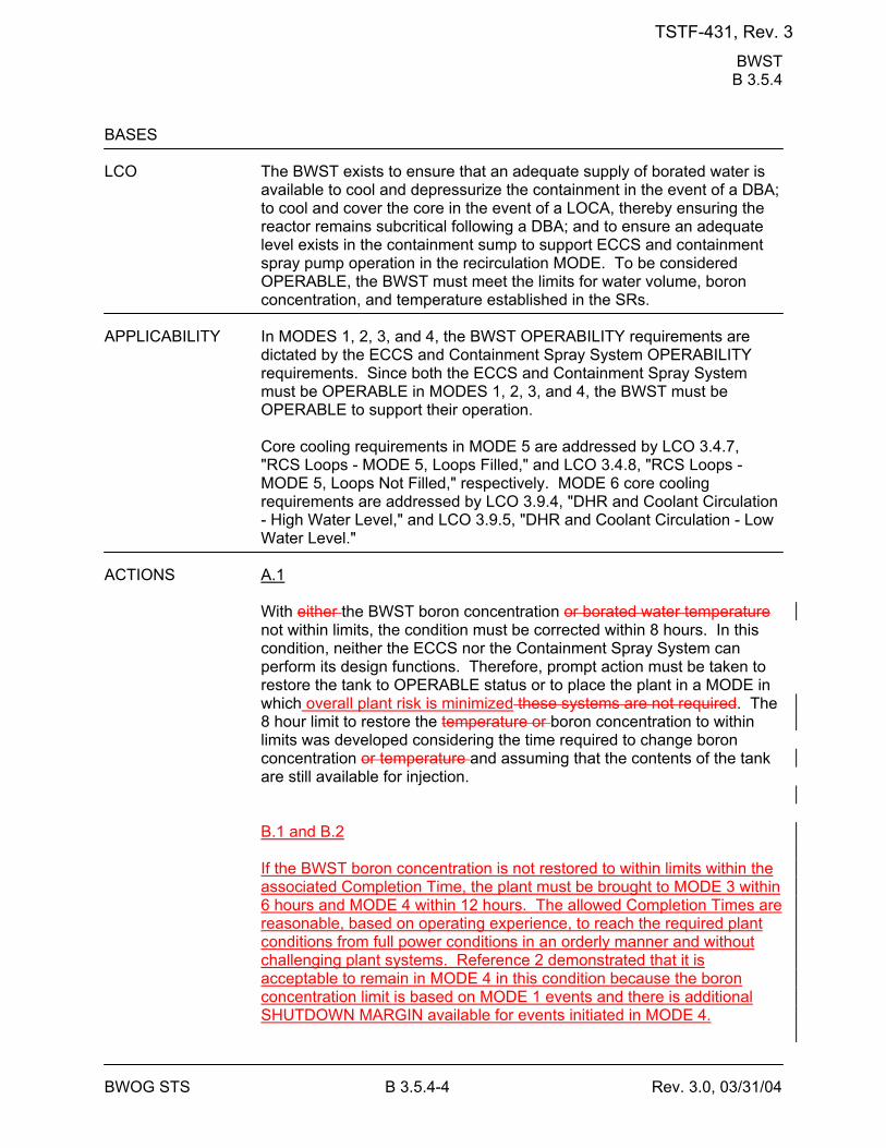
BWST B 3.5.4
BWOG STS B 3.5.4-4 Rev. 3.0, 03/31/04
BASES LCO The BWST exists to ensure that an adequate supply of borated water is
available to cool and depressurize the containment in the event of a DBA; to cool and cover the core in the event of a LOCA, thereby ensuring the reactor remains subcritical following a DBA; and to ensure an adequate level exists in the containment sump to support ECCS and containment spray pump operation in the recirculation MODE. To be considered OPERABLE, the BWST must meet the limits for water volume, boron concentration, and temperature established in the SRs.
APPLICABILITY In MODES 1, 2, 3, and 4, the BWST OPERABILITY requirements are
dictated by the ECCS and Containment Spray System OPERABILITY requirements. Since both the ECCS and Containment Spray System must be OPERABLE in MODES 1, 2, 3, and 4, the BWST must be OPERABLE to support their operation.
Core cooling requirements in MODE 5 are addressed by LCO 3.4.7, "RCS Loops - MODE 5, Loops Filled," and LCO 3.4.8, "RCS Loops - MODE 5, Loops Not Filled," respectively. MODE 6 core cooling requirements are addressed by LCO 3.9.4, "DHR and Coolant Circulation - High Water Level," and LCO 3.9.5, "DHR and Coolant Circulation - Low Water Level."
ACTIONS A.1
With either the BWST boron concentration or borated water temperature not within limits, the condition must be corrected within 8 hours. In this condition, neither the ECCS nor the Containment Spray System can perform its design functions. Therefore, prompt action must be taken to restore the tank to OPERABLE status or to place the plant in a MODE in which overall plant risk is minimized these systems are not required. The 8 hour limit to restore the temperature or boron concentration to within limits was developed considering the time required to change boron concentration or temperature and assuming that the contents of the tank are still available for injection. B.1 and B.2 If the BWST boron concentration is not restored to within limits within the associated Completion Time, the plant must be brought to MODE 3 within 6 hours and MODE 4 within 12 hours. The allowed Completion Times are reasonable, based on operating experience, to reach the required plant conditions from full power conditions in an orderly manner and without challenging plant systems. Reference 2 demonstrated that it is acceptable to remain in MODE 4 in this condition because the boron concentration limit is based on MODE 1 events and there is additional SHUTDOWN MARGIN available for events initiated in MODE 4.
TSTF-431, Rev. 3
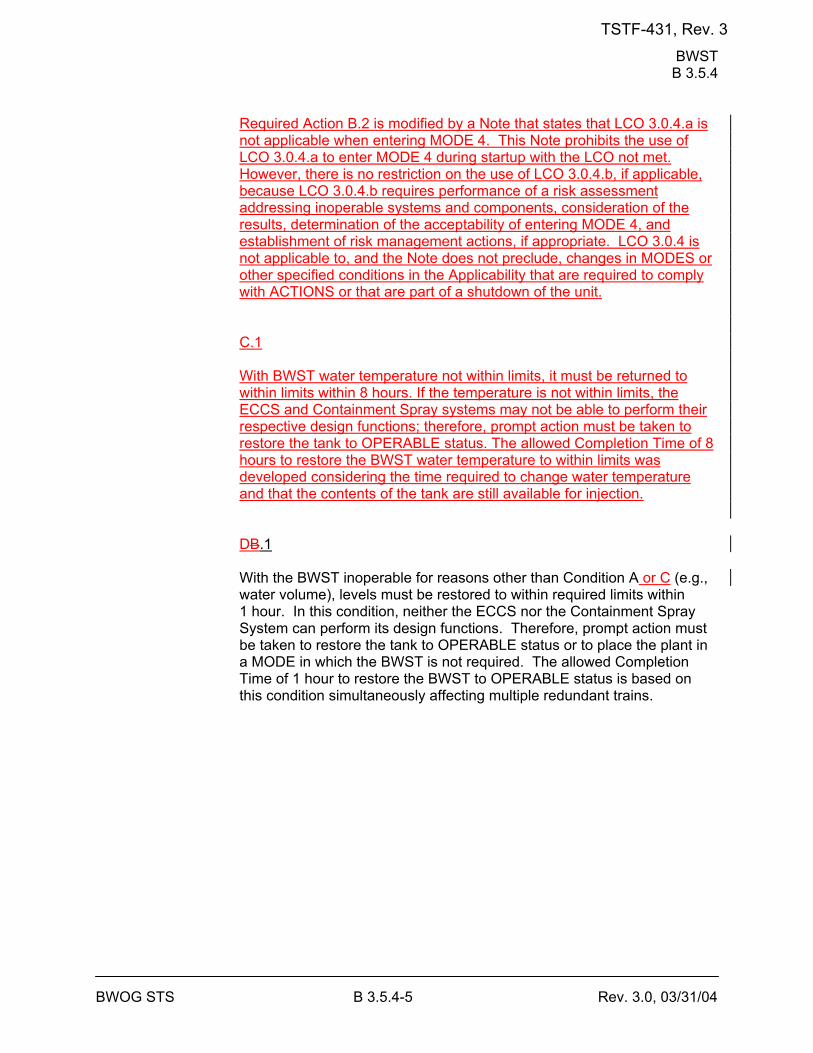
BWST B 3.5.4
BWOG STS B 3.5.4-5 Rev. 3.0, 03/31/04
Required Action B.2 is modified by a Note that states that LCO 3.0.4.a is not applicable when entering MODE 4. This Note prohibits the use of LCO 3.0.4.a to enter MODE 4 during startup with the LCO not met. However, there is no restriction on the use of LCO 3.0.4.b, if applicable, because LCO 3.0.4.b requires performance of a risk assessment addressing inoperable systems and components, consideration of the results, determination of the acceptability of entering MODE 4, and establishment of risk management actions, if appropriate. LCO 3.0.4 is not applicable to, and the Note does not preclude, changes in MODES or other specified conditions in the Applicability that are required to comply with ACTIONS or that are part of a shutdown of the unit. C.1 With BWST water temperature not within limits, it must be returned to within limits within 8 hours. If the temperature is not within limits, the ECCS and Containment Spray systems may not be able to perform their respective design functions; therefore, prompt action must be taken to restore the tank to OPERABLE status. The allowed Completion Time of 8 hours to restore the BWST water temperature to within limits was developed considering the time required to change water temperature and that the contents of the tank are still available for injection. DB.1 With the BWST inoperable for reasons other than Condition A or C (e.g., water volume), levels must be restored to within required limits within 1 hour. In this condition, neither the ECCS nor the Containment Spray System can perform its design functions. Therefore, prompt action must be taken to restore the tank to OPERABLE status or to place the plant in a MODE in which the BWST is not required. The allowed Completion Time of 1 hour to restore the BWST to OPERABLE status is based on this condition simultaneously affecting multiple redundant trains.
TSTF-431, Rev. 3
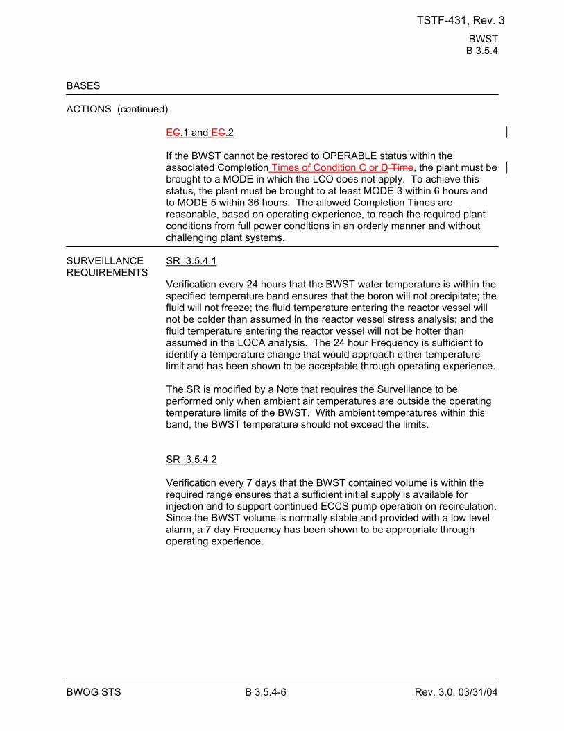
BWST B 3.5.4
BWOG STS B 3.5.4-6 Rev. 3.0, 03/31/04
BASES ACTIONS (continued)
EC.1 and EC.2 If the BWST cannot be restored to OPERABLE status within the associated Completion Times of Condition C or D Time, the plant must be brought to a MODE in which the LCO does not apply. To achieve this status, the plant must be brought to at least MODE 3 within 6 hours and to MODE 5 within 36 hours. The allowed Completion Times are reasonable, based on operating experience, to reach the required plant conditions from full power conditions in an orderly manner and without challenging plant systems.
SURVEILLANCE SR 3.5.4.1 REQUIREMENTS
Verification every 24 hours that the BWST water temperature is within the specified temperature band ensures that the boron will not precipitate; the fluid will not freeze; the fluid temperature entering the reactor vessel will not be colder than assumed in the reactor vessel stress analysis; and the fluid temperature entering the reactor vessel will not be hotter than assumed in the LOCA analysis. The 24 hour Frequency is sufficient to identify a temperature change that would approach either temperature limit and has been shown to be acceptable through operating experience. The SR is modified by a Note that requires the Surveillance to be performed only when ambient air temperatures are outside the operating temperature limits of the BWST. With ambient temperatures within this band, the BWST temperature should not exceed the limits. SR 3.5.4.2 Verification every 7 days that the BWST contained volume is within the required range ensures that a sufficient initial supply is available for injection and to support continued ECCS pump operation on recirculation. Since the BWST volume is normally stable and provided with a low level alarm, a 7 day Frequency has been shown to be appropriate through operating experience.
TSTF-431, Rev. 3
BWST B 3.5.4
BWOG STS B 3.5.4-7 Rev. 3.0, 03/31/04
BASES SURVEILLANCE REQUIREMENTS (continued)
SR 3.5.4.3 Verification every 7 days that the boron concentration of the BWST fluid is within the required band ensures that the reactor will remain subcritical following a LOCA. Since the BWST volume is normally stable, a 7 day sampling Frequency is appropriate and has been shown to be acceptable through operating experience.
REFERENCES 1. FSAR, Section [6.1]. 2. BAW-2441-A, Revision 2, Risk Informed Justification for LCO End-
State Changes, September 2006.
TSTF-431, Rev. 3
Containment Air Locks B 3.6.2
BWOG STS B 3.6.2-6 Rev. 3.0, 03/31/04
BASES ACTIONS (continued)
D.1 and D.2 If the inoperable containment air lock cannot be restored to OPERABLE status within the required Completion Time, the plant must be brought to a MODE in which the LCO does not apply overall plant risk is minimized. To achieve this status, the plant must be brought to at least MODE 3 within 6 hours and to MODE 45 within 36 12 hours. Remaining within the Applicability of the LCO is acceptable because the plant risk in MODE 4 is similar to or lower than MODE 5 (Ref. 4). The release of stored energy to the Reactor Building in the event of an accident in MODE 4 is substantially less than the energy release assumed due to an accident at power. Therefore, the challenge to containment air locks is substantially reduced. Because of the reduction in RCS pressure and temperature in MODE 4, the likelihood of an event is also reduced. In addition, there are more accident mitigation systems available and there is more redundancy and diversity in core heat removal mechanisms in MODE 4 than in MODE 5. However, voluntary entry into MODE 5 may be made as it is also an acceptable low-risk state. Required Action D.2 is modified by a Note that states that LCO 3.0.4.a is not applicable when entering MODE 4. This Note prohibits the use of LCO 3.0.4.a to enter MODE 4 during startup with the LCO not met. However, there is no restriction on the use of LCO 3.0.4.b, if applicable, because LCO 3.0.4.b requires performance of a risk assessment addressing inoperable systems and components, consideration of the results, determination of the acceptability of entering MODE 4, and establishment of risk management actions, if appropriate. LCO 3.0.4 is not applicable to, and the Note does not preclude, changes in MODES or other specified conditions in the Applicability that are required to comply with ACTIONS or that are part of a shutdown of the unit. The allowed Completion Times are reasonable, based on operating experience, to reach the required plant conditions from full power conditions in an orderly manner and without challenging plant systems.
SURVEILLANCE SR 3.6.2.1 REQUIREMENTS
Maintaining containment air locks OPERABLE requires compliance with the leakage rate test requirements of the Containment Leakage Rate Testing Program. This SR reflects the leakage rate testing requirements with regard to air lock leakage (Type B leakage tests). The acceptance criteria were established during initial air lock and containment OPERABILITY testing. The periodic testing requirements verify that the air lock leakage does not exceed the allowed fraction of the overall
TSTF-431, Rev. 3
Containment Air Locks B 3.6.2
BWOG STS B 3.6.2-8 Rev. 3.0, 03/31/04
BASES SURVEILLANCE REQUIREMENTS (continued)
that the interlock will function as designed and that simultaneous opening of the inner and outer doors will not inadvertently occur. Due to the purely mechanical nature of this interlock, and given that the interlock mechanism is not normally challenged when the containment air lock door is used for entry and exit (procedures require strict adherence to single door opening), this test is only required to be performed every 24 months. The 24 month Frequency is based on the need to perform this Surveillance under the conditions that apply during a plant outage, and the potential for loss of containment OPERABILITY if the Surveillance were performed with the reactor at power. Operating experience has shown these components usually pass the Surveillance when performed at the 24 month Frequency. The 24 month Frequency is based on engineering judgment and is considered adequate given that the interlock is not challenged during the use of the airlock.
REFERENCES 1. 10 CFR 50, Appendix J, Option [A][B]. 2. FSAR, Sections [14.1 and 14.2]. 3. FSAR, Section [5.6]. 4. BAW-2441-A, Revision 2, Risk Informed Justification for LCO End-
State Changes, September 2006.
TSTF-431, Rev. 3
Containment Isolation Valves B 3.6.3
BWOG STS B 3.6.3-9 Rev. 3.0, 03/31/04
BASES ACTIONS (continued)
Required Action does not require any testing or valve manipulation. Rather, it involves verification that those isolation devices outside containment and potentially capable of being mispositioned are in the correct position. For the isolation devices inside containment, the time period specified as "prior to entering MODE 4 from MODE 5 if not performed within the previous 92 days" is based on engineering judgment and is considered reasonable in view of the inaccessibility of the isolation devices and other administrative controls that will ensure that isolation device misalignment is an unlikely possibility. For the containment purge valve with resilient seal that is isolated in accordance with Required Action D.1, SR 3.6.3.6 must be performed at least once every [ ] days. This provides assurance that degradation of the resilient seal is detected and confirms that the leakage rate of the containment purge valve does not increase during the time the penetration is isolated. The normal Frequency for SR 3.6.3.6, 184 days, is based on an NRC initiative, Generic Issue B-20 (Ref. 78). Since more reliance is placed on a single valve while in this Condition, it is prudent to perform the SR more often. Therefore, a Frequency of once per [ ] days was chosen and has been shown acceptable based on operating experience. Required Action D.2 is modified by two Notes. Note 1 applies to isolation devices located in high radiation areas and allows these devices to be verified closed by use of administrative means. Allowing verification by administrative means is considered acceptable, since access to these areas is typically restricted. Note 2 applies to isolation devices that are locked, sealed, or otherwise secured in position and allows these devices to be verified closed by use of administrative means. Allowing verification by administrative means is considered acceptable, since the function of locking, sealing, or securing components is to ensure that these devices are not inadvertently repositioned. ] E.1 and E.2 If the Required Actions and associated Completion Times are not met, the plant must be brought to a MODE in which the LCO does not applyoverall plant risk is minimized. To achieve this status, the plant must be brought to at least MODE 3 within 6 hours and to MODE 45 within 1236 hours. Remaining within the Applicability of the LCO is acceptable because the plant risk in MODE 4 is similar to or lower than MODE 5 (Ref. 8). The release of stored energy to the Reactor Building in the event of an accident in MODE 4 is substantially less than the energy release
TSTF-431, Rev. 3
Containment Isolation Valves B 3.6.3
BWOG STS B 3.6.3-10 Rev. 3.0, 03/31/04
assumed due to an accident at power. Therefore, the challenge to containment isolation valves is substantially reduced. Because of the reduction in RCS pressure and temperature in MODE 4, the likelihood of an event is also reduced. In addition, there are more accident mitigation systems available and there is more redundancy and diversity in core heat removal mechanisms in MODE 4 than in MODE 5. However, voluntary entry into MODE 5 may be made as it is also an acceptable low-risk state. Required Action E.2 is modified by a Note that states that LCO 3.0.4.a is not applicable when entering MODE 4. This Note prohibits the use of LCO 3.0.4.a to enter MODE 4 during startup with the LCO not met. However, there is no restriction on the use of LCO 3.0.4.b, if applicable, because LCO 3.0.4.b requires performance of a risk assessment addressing inoperable systems and components, consideration of the results, determination of the acceptability of entering MODE 4, and establishment of risk management actions, if appropriate. LCO 3.0.4 is not applicable to, and the Note does not preclude, changes in MODES or other specified conditions in the Applicability that are required to comply with ACTIONS or that are part of a shutdown of the unit. The allowed Completion Times are reasonable, based on operating experience, to reach the required plant conditions from full power conditions in an orderly manner and without challenging plant systems.
TSTF-431, Rev. 3
Containment Isolation Valves B 3.6.3
BWOG STS B 3.6.3-11 Rev. 3.0, 03/31/04
BASES SURVEILLANCE [ SR 3.6.3.1 REQUIREMENTS
Each [48] inch containment purge valve is required to be verified sealed closed at 31 day intervals. This Surveillance is designed to ensure that a gross breach of containment is not caused by an inadvertent or spurious opening of a containment purge valve. Detailed analysis of the purge valves failed to conclusively demonstrate their ability to close during a LOCA in time to limit offsite doses. Therefore, these valves are required to be in the sealed closed position during MODES 1, 2, 3, and 4. A containment purge valve that is sealed closed must have motive power to the valve operator removed. This can be accomplished by de-energizing the source of electric power or by removing the air supply to the valve operator. In this application, the term "sealed" has no connotation of leak tightness. The Frequency is a result of an NRC initiative, Generic Issue B-24 (Ref. 97), related to containment purge valve use during unit operations. In the event purge valve leakage requires entry into Condition D, the Surveillance permits opening one purge valve in a penetration flow path to perform repairs. ] SR 3.6.3.2 This SR ensures that the minipurge valves are closed as required or, if open, open for an allowable reason. If a purge valve is open in violation of this SR, the valve is considered inoperable. If the inoperable valve is not otherwise known to have excessive leakage when closed, it is not considered to have leakage outside of limits. The SR is not required to be met when the minipurge valves are open for pressure control, ALARA or air quality considerations for personnel entry, or for Surveillances that require the valves to be open. The minipurge valves are capable of closing in the environment following a LOCA. Therefore, these valves are allowed to be open for limited periods of time. The 31 day Frequency is consistent with other containment isolation valve requirements discussed in SR 3.6.3.3. SR 3.6.3.3 This SR requires verification that each containment isolation manual valve and blind flange located outside containment and not locked, sealed, or otherwise secured and required to be closed during accident conditions is closed. The SR helps to ensure that post accident leakage of radioactive fluids or gases outside the containment boundary is within
TSTF-431, Rev. 3
Containment Isolation Valves B 3.6.3
BWOG STS B 3.6.3-13 Rev. 3.0, 03/31/04
BASES SURVEILLANCE REQUIREMENTS (continued)
The Note allows valves and blind flanges located in high radiation areas to be verified closed by use of administrative means. Allowing verification by administrative means is considered acceptable, since the access to these areas is typically restricted during MODES 1, 2, 3, and 4 for ALARA reasons. Therefore, the probability of misalignment of these containment isolation valves, once they have been verified to be in their proper position, is small. SR 3.6.3.5 Verifying that the isolation time of each automatic power operated containment isolation valve is within limits is required to demonstrate OPERABILITY. The isolation time test ensures the valve will isolate in a time period less than or equal to that assumed in the safety analyses. [The isolation time and Frequency of this SR are in accordance with the Inservice Testing Program or 92 days.] SR 3.6.3.6 For containment purge valves with resilient seals, additional leakage rate testing beyond the test requirements of 10 CFR 50, Appendix J, Option [A][B] is required to ensure OPERABILITY. Operating experience has demonstrated that this type of seal has the potential to degrade in a shorter time period than do other seal types. Based on this observation and the importance of maintaining this penetration leak tight (due to the direct path between containment and the environment), a Frequency of once per 184 days was established as part of the NRC resolution of Generic Issue B-20, "Containment Leakage Due to Seal Deterioration" (Ref. 78). Additionally, this SR must be performed within 92 days after opening the valve. The 92 day Frequency was chosen recognizing that cycling the valve could introduce additional seal degradation (greater than that occurring to a valve that has not been opened). Thus, decreasing the interval (from 184 days) is a prudent measure after a valve has been opened.
TSTF-431, Rev. 3
Containment Isolation Valves B 3.6.3
BWOG STS B 3.6.3-15 Rev. 3.0, 03/31/04
BASES REFERENCES 1. 10 CFR 20. 2. FSAR, Section [5.6]. 3. FSAR, Sections [14.1 and 14.2]. 4. FSAR, Section [5.3]. 5. FSAR, Section [5.3]. 6. Standard Review Plan 6.2.4. 7. Generic Issue B-2420. 8. BAW-2441-A, Revision 2, Risk Informed Justification for LCO End-
State Changes, September 2006. 98. Generic Issue B-2420.
TSTF-431, Rev. 3
Containment Pressure B 3.6.4
BWOG STS B 3.6.4-2 Rev. 3.0, 03/31/04
BASES BACKGROUND (continued)
containment backpressure is calculated in a manner designed to conservatively minimize, rather than maximize, the containment pressure response in accordance with 10 CFR 50, Appendix K (Ref. 2). Containment pressure satisfies Criterion 2 of 10 CFR 50.36(c)(2)(ii).
LCO Maintaining containment pressure less than or equal to the LCO upper
pressure limit ensures that, in the event of a DBA, the resultant peak containment accident pressure will remain below the containment design pressure. Maintaining containment pressure greater than or equal to the LCO lower pressure limit ensures that the containment will not exceed the design negative differential pressure following the inadvertent actuation of the Containment Spray System.
APPLICABILITY In MODES 1, 2, 3, and 4, a DBA could cause a release of radioactive
material to containment. Since maintaining containment pressure within design basis limits is essential to ensure initial conditions assumed in the accident analysis are maintained, the LCO is applicable in MODES 1, 2, 3, and 4.
In MODES 5 and 6, the probability and consequences of these events are reduced due to the pressure and temperature limitations of these MODES. Therefore, maintaining containment pressure within the limits of the LCO is not required in MODES 5 and 6.
ACTIONS A.1
When containment pressure is not within the limits of the LCO, containment pressure must be restored to within these limits within 1 hour. The Required Action is necessary to return operation to within the bounds of the containment analysis. The 1 hour Completion Time is consistent with the ACTIONS of LCO 3.6.1, "Containment," which requires that containment be restored to OPERABLE status within 1 hour. B.1 and B.2
If containment pressure cannot be restored within limits within the required Completion Time, the plant must be brought to a MODE in which the LCO does not applyoverall plant risk is minimized. To achieve this status, the plant must be brought to at least MODE 3 within 6 hours and to MODE 45 within 1236 hours. Remaining within the Applicability of the LCO is acceptable because the plant risk in MODE 4 is similar to or lower than MODE 5 (Ref. 3). The release of stored energy to the Reactor Building in the event of an
TSTF-431, Rev. 3
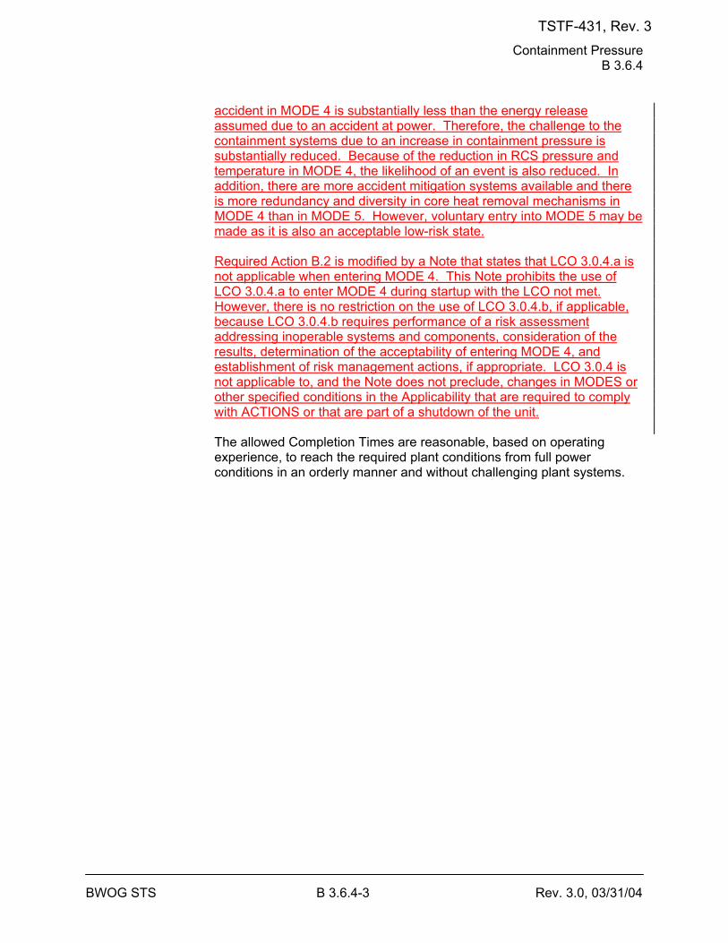
Containment Pressure B 3.6.4
BWOG STS B 3.6.4-3 Rev. 3.0, 03/31/04
accident in MODE 4 is substantially less than the energy release assumed due to an accident at power. Therefore, the challenge to the containment systems due to an increase in containment pressure is substantially reduced. Because of the reduction in RCS pressure and temperature in MODE 4, the likelihood of an event is also reduced. In addition, there are more accident mitigation systems available and there is more redundancy and diversity in core heat removal mechanisms in MODE 4 than in MODE 5. However, voluntary entry into MODE 5 may be made as it is also an acceptable low-risk state. Required Action B.2 is modified by a Note that states that LCO 3.0.4.a is not applicable when entering MODE 4. This Note prohibits the use of LCO 3.0.4.a to enter MODE 4 during startup with the LCO not met. However, there is no restriction on the use of LCO 3.0.4.b, if applicable, because LCO 3.0.4.b requires performance of a risk assessment addressing inoperable systems and components, consideration of the results, determination of the acceptability of entering MODE 4, and establishment of risk management actions, if appropriate. LCO 3.0.4 is not applicable to, and the Note does not preclude, changes in MODES or other specified conditions in the Applicability that are required to comply with ACTIONS or that are part of a shutdown of the unit. The allowed Completion Times are reasonable, based on operating experience, to reach the required plant conditions from full power conditions in an orderly manner and without challenging plant systems.
TSTF-431, Rev. 3
Containment Pressure B 3.6.4
BWOG STS B 3.6.4-4 Rev. 3.0, 03/31/04
BASES SURVEILLANCE SR 3.6.4.1 REQUIREMENTS
Verifying that containment pressure is within limits ensures that operation remains within the limits assumed in the containment analysis. The 12 hour Frequency of this SR was developed after taking into consideration operating experience related to trending of containment pressure variations during the applicable MODES. Furthermore, the 12 hour Frequency is considered adequate in view of other indications available in the control room, including alarms, to alert the operator to an abnormal containment pressure condition.
REFERENCES 1. FSAR, Section [14.2]. 2. 10 CFR 50, Appendix K. 3. BAW-2441-A, Revision 2, Risk Informed Justification for LCO End-
State Changes, September 2006.
TSTF-431, Rev. 3
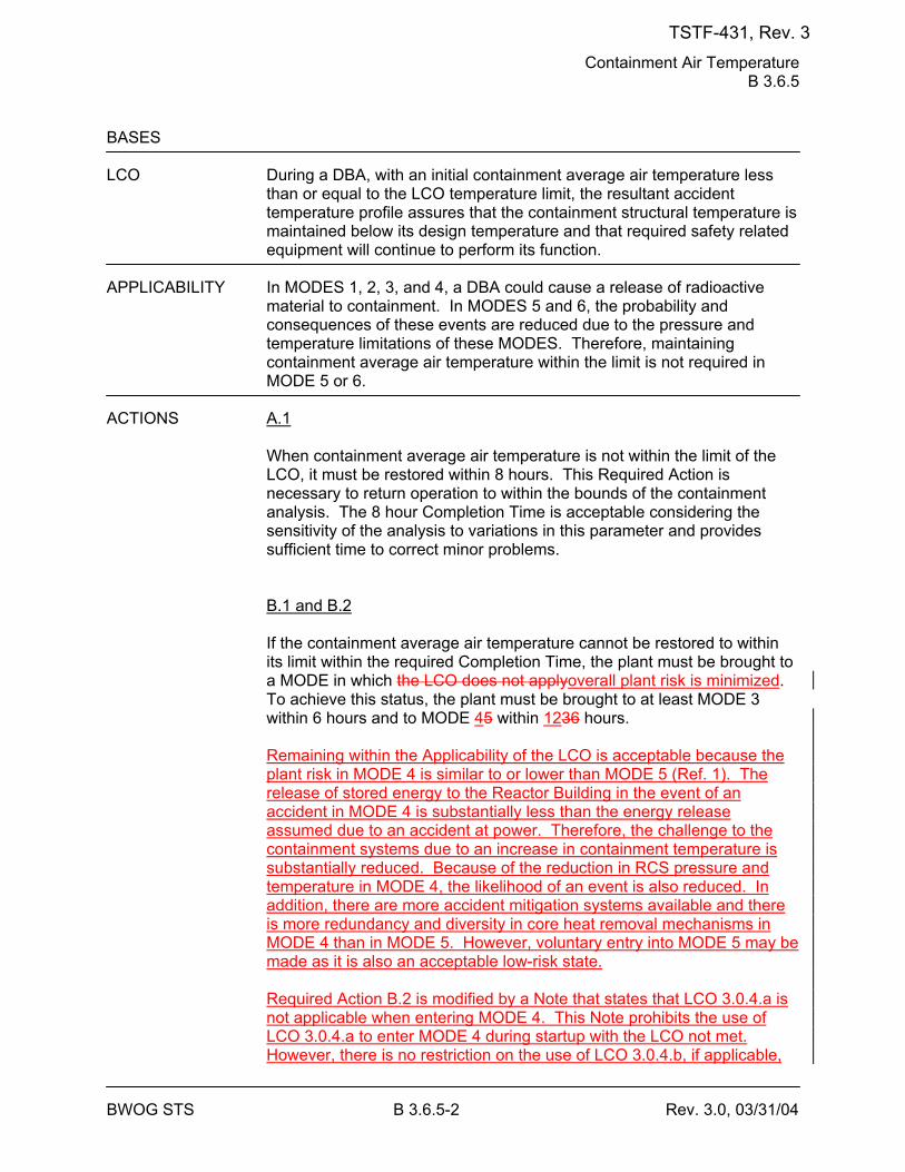
Containment Air Temperature B 3.6.5
BWOG STS B 3.6.5-2 Rev. 3.0, 03/31/04
BASES LCO During a DBA, with an initial containment average air temperature less
than or equal to the LCO temperature limit, the resultant accident temperature profile assures that the containment structural temperature is maintained below its design temperature and that required safety related equipment will continue to perform its function.
APPLICABILITY In MODES 1, 2, 3, and 4, a DBA could cause a release of radioactive
material to containment. In MODES 5 and 6, the probability and consequences of these events are reduced due to the pressure and temperature limitations of these MODES. Therefore, maintaining containment average air temperature within the limit is not required in MODE 5 or 6.
ACTIONS A.1
When containment average air temperature is not within the limit of the LCO, it must be restored within 8 hours. This Required Action is necessary to return operation to within the bounds of the containment analysis. The 8 hour Completion Time is acceptable considering the sensitivity of the analysis to variations in this parameter and provides sufficient time to correct minor problems. B.1 and B.2 If the containment average air temperature cannot be restored to within its limit within the required Completion Time, the plant must be brought to a MODE in which the LCO does not applyoverall plant risk is minimized. To achieve this status, the plant must be brought to at least MODE 3 within 6 hours and to MODE 45 within 1236 hours. Remaining within the Applicability of the LCO is acceptable because the plant risk in MODE 4 is similar to or lower than MODE 5 (Ref. 1). The release of stored energy to the Reactor Building in the event of an accident in MODE 4 is substantially less than the energy release assumed due to an accident at power. Therefore, the challenge to the containment systems due to an increase in containment temperature is substantially reduced. Because of the reduction in RCS pressure and temperature in MODE 4, the likelihood of an event is also reduced. In addition, there are more accident mitigation systems available and there is more redundancy and diversity in core heat removal mechanisms in MODE 4 than in MODE 5. However, voluntary entry into MODE 5 may be made as it is also an acceptable low-risk state. Required Action B.2 is modified by a Note that states that LCO 3.0.4.a is not applicable when entering MODE 4. This Note prohibits the use of LCO 3.0.4.a to enter MODE 4 during startup with the LCO not met. However, there is no restriction on the use of LCO 3.0.4.b, if applicable,
TSTF-431, Rev. 3
Containment Air Temperature B 3.6.5
BWOG STS B 3.6.5-3 Rev. 3.0, 03/31/04
because LCO 3.0.4.b requires performance of a risk assessment addressing inoperable systems and components, consideration of the results, determination of the acceptability of entering MODE 4, and establishment of risk management actions, if appropriate. LCO 3.0.4 is not applicable to, and the Note does not preclude, changes in MODES or other specified conditions in the Applicability that are required to comply with ACTIONS or that are part of a shutdown of the unit. The allowed Completion Times are reasonable, based on operating experience, to reach the required plant conditions from full power conditions in an orderly manner and without challenging plant systems.
TSTF-431, Rev. 3
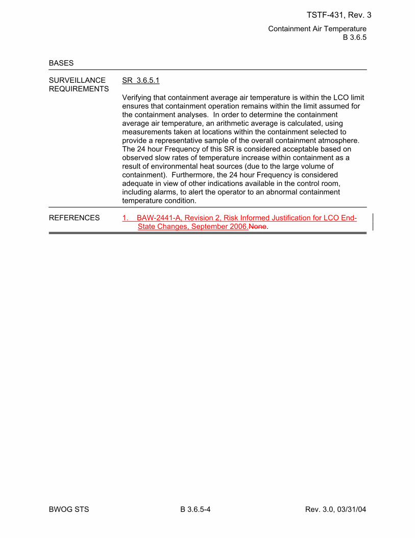
Containment Air Temperature B 3.6.5
BWOG STS B 3.6.5-4 Rev. 3.0, 03/31/04
BASES SURVEILLANCE SR 3.6.5.1 REQUIREMENTS
Verifying that containment average air temperature is within the LCO limit ensures that containment operation remains within the limit assumed for the containment analyses. In order to determine the containment average air temperature, an arithmetic average is calculated, using measurements taken at locations within the containment selected to provide a representative sample of the overall containment atmosphere. The 24 hour Frequency of this SR is considered acceptable based on observed slow rates of temperature increase within containment as a result of environmental heat sources (due to the large volume of containment). Furthermore, the 24 hour Frequency is considered adequate in view of other indications available in the control room, including alarms, to alert the operator to an abnormal containment temperature condition.
REFERENCES 1. BAW-2441-A, Revision 2, Risk Informed Justification for LCO End-
State Changes, September 2006.None.
TSTF-431, Rev. 3
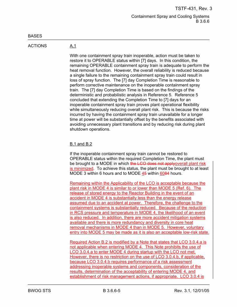
Containment Spray and Cooling Systems B 3.6.6
BWOG STS B 3.6.6-5 Rev. 3.1, 12/01/05
BASES ACTIONS A.1
With one containment spray train inoperable, action must be taken to restore it to OPERABLE status within [7] days. In this condition, the remaining OPERABLE containment spray train is adequate to perform the heat removal function. However, the overall reliability is reduced because a single failure to the remaining containment spray train could result in loss of spray function. The [7] day Completion Time is reasonable to perform corrective maintenance on the inoperable containment spray train. The [7] day Completion Time is based on the findings of the deterministic and probabilistic analysis in Reference 5. Reference 5 concluded that extending the Completion Time to [7] days for an inoperable containment spray train proves plant operational flexibility while simultaneously reducing overall plant risk. This is because the risks incurred by having the containment spray train unavailable for a longer time at power will be substantially offset by the benefits associated with avoiding unnecessary plant transitions and by reducing risk during plant shutdown operations. B.1 and B.2 If the inoperable containment spray train cannot be restored to OPERABLE status within the required Completion Time, the plant must be brought to a MODE in which the LCO does not applyoverall plant risk is minimized. To achieve this status, the plant must be brought to at least MODE 3 within 6 hours and to MODE 45 within 6084 hours. Remaining within the Applicability of the LCO is acceptable because the plant risk in MODE 4 is similar to or lower than MODE 5 (Ref. 6). The release of stored energy to the Reactor Building in the event of an accident in MODE 4 is substantially less than the energy release assumed due to an accident at power. Therefore, the challenge to the containment systems is substantially reduced. Because of the reduction in RCS pressure and temperature in MODE 4, the likelihood of an event is also reduced. In addition, there are more accident mitigation systems available and there is more redundancy and diversity in core heat removal mechanisms in MODE 4 than in MODE 5. However, voluntary entry into MODE 5 may be made as it is also an acceptable low-risk state. Required Action B.2 is modified by a Note that states that LCO 3.0.4.a is not applicable when entering MODE 4. This Note prohibits the use of LCO 3.0.4.a to enter MODE 4 during startup with the LCO not met. However, there is no restriction on the use of LCO 3.0.4.b, if applicable, because LCO 3.0.4.b requires performance of a risk assessment addressing inoperable systems and components, consideration of the results, determination of the acceptability of entering MODE 4, and establishment of risk management actions, if appropriate. LCO 3.0.4 is
TSTF-431, Rev. 3
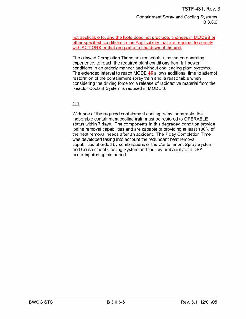
Containment Spray and Cooling Systems B 3.6.6
BWOG STS B 3.6.6-6 Rev. 3.1, 12/01/05
not applicable to, and the Note does not preclude, changes in MODES or other specified conditions in the Applicability that are required to comply with ACTIONS or that are part of a shutdown of the unit. The allowed Completion Times are reasonable, based on operating experience, to reach the required plant conditions from full power conditions in an orderly manner and without challenging plant systems. The extended interval to reach MODE 45 allows additional time to attempt restoration of the containment spray train and is reasonable when considering the driving force for a release of radioactive material from the Reactor Coolant System is reduced in MODE 3. C.1 With one of the required containment cooling trains inoperable, the inoperable containment cooling train must be restored to OPERABLE status within 7 days. The components in this degraded condition provide iodine removal capabilities and are capable of providing at least 100% of the heat removal needs after an accident. The 7 day Completion Time was developed taking into account the redundant heat removal capabilities afforded by combinations of the Containment Spray System and Containment Cooling System and the low probability of a DBA occurring during this period.
TSTF-431, Rev. 3
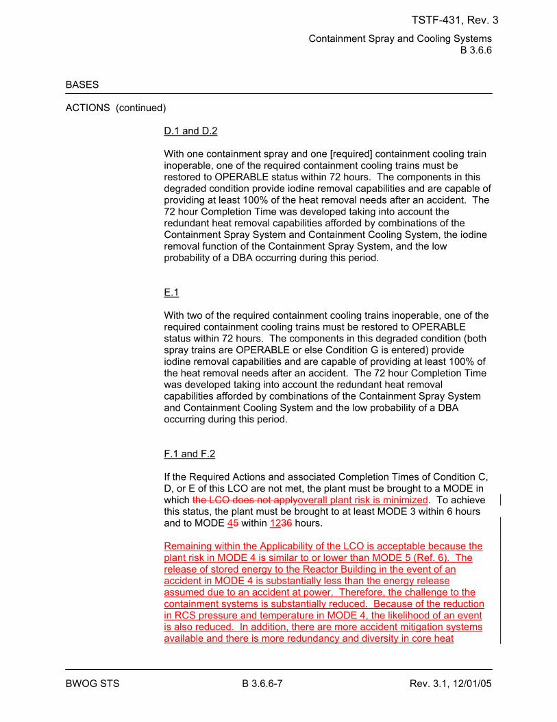
Containment Spray and Cooling Systems B 3.6.6
BWOG STS B 3.6.6-7 Rev. 3.1, 12/01/05
BASES ACTIONS (continued)
D.1 and D.2 With one containment spray and one [required] containment cooling train inoperable, one of the required containment cooling trains must be restored to OPERABLE status within 72 hours. The components in this degraded condition provide iodine removal capabilities and are capable of providing at least 100% of the heat removal needs after an accident. The 72 hour Completion Time was developed taking into account the redundant heat removal capabilities afforded by combinations of the Containment Spray System and Containment Cooling System, the iodine removal function of the Containment Spray System, and the low probability of a DBA occurring during this period. E.1 With two of the required containment cooling trains inoperable, one of the required containment cooling trains must be restored to OPERABLE status within 72 hours. The components in this degraded condition (both spray trains are OPERABLE or else Condition G is entered) provide iodine removal capabilities and are capable of providing at least 100% of the heat removal needs after an accident. The 72 hour Completion Time was developed taking into account the redundant heat removal capabilities afforded by combinations of the Containment Spray System and Containment Cooling System and the low probability of a DBA occurring during this period. F.1 and F.2 If the Required Actions and associated Completion Times of Condition C, D, or E of this LCO are not met, the plant must be brought to a MODE in which the LCO does not applyoverall plant risk is minimized. To achieve this status, the plant must be brought to at least MODE 3 within 6 hours and to MODE 45 within 1236 hours. Remaining within the Applicability of the LCO is acceptable because the plant risk in MODE 4 is similar to or lower than MODE 5 (Ref. 6). The release of stored energy to the Reactor Building in the event of an accident in MODE 4 is substantially less than the energy release assumed due to an accident at power. Therefore, the challenge to the containment systems is substantially reduced. Because of the reduction in RCS pressure and temperature in MODE 4, the likelihood of an event is also reduced. In addition, there are more accident mitigation systems available and there is more redundancy and diversity in core heat
TSTF-431, Rev. 3
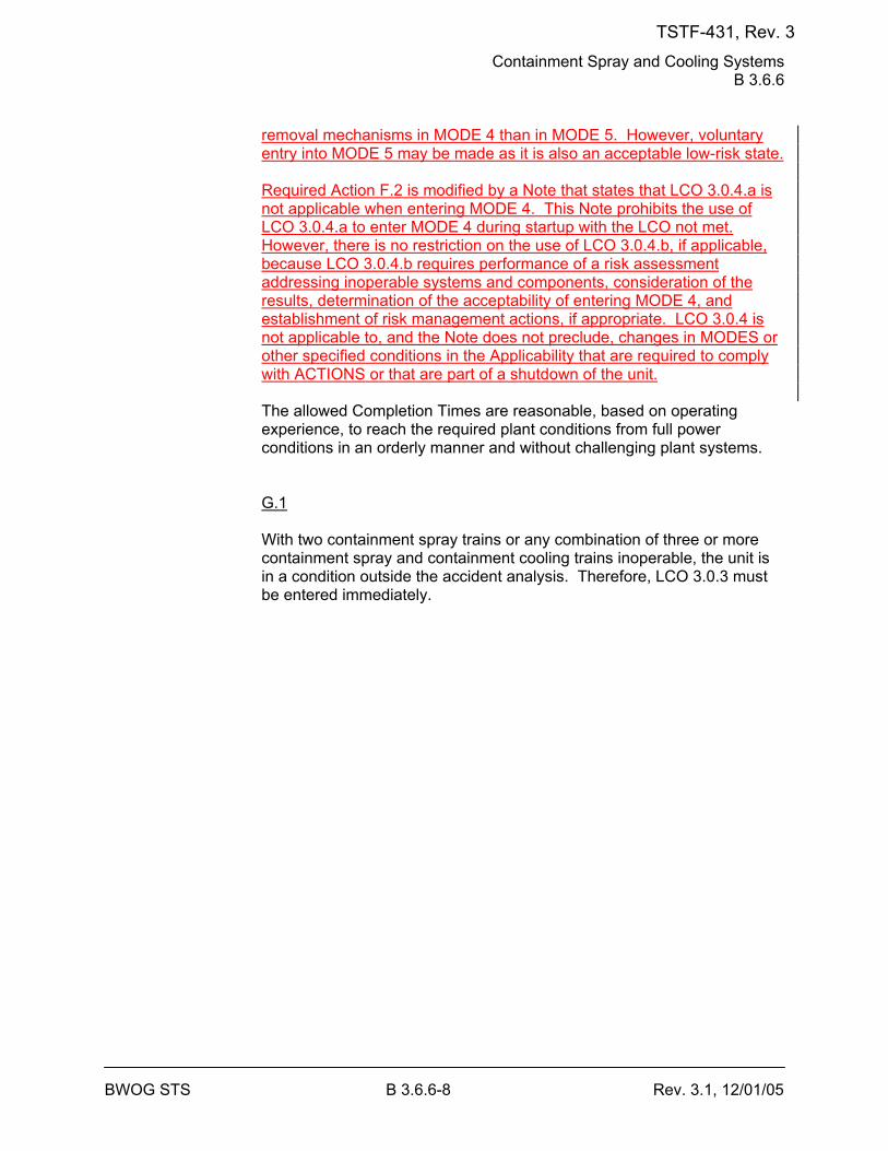
Containment Spray and Cooling Systems B 3.6.6
BWOG STS B 3.6.6-8 Rev. 3.1, 12/01/05
removal mechanisms in MODE 4 than in MODE 5. However, voluntary entry into MODE 5 may be made as it is also an acceptable low-risk state. Required Action F.2 is modified by a Note that states that LCO 3.0.4.a is not applicable when entering MODE 4. This Note prohibits the use of LCO 3.0.4.a to enter MODE 4 during startup with the LCO not met. However, there is no restriction on the use of LCO 3.0.4.b, if applicable, because LCO 3.0.4.b requires performance of a risk assessment addressing inoperable systems and components, consideration of the results, determination of the acceptability of entering MODE 4, and establishment of risk management actions, if appropriate. LCO 3.0.4 is not applicable to, and the Note does not preclude, changes in MODES or other specified conditions in the Applicability that are required to comply with ACTIONS or that are part of a shutdown of the unit. The allowed Completion Times are reasonable, based on operating experience, to reach the required plant conditions from full power conditions in an orderly manner and without challenging plant systems. G.1 With two containment spray trains or any combination of three or more containment spray and containment cooling trains inoperable, the unit is in a condition outside the accident analysis. Therefore, LCO 3.0.3 must be entered immediately.
TSTF-431, Rev. 3
Containment Spray and Cooling Systems B 3.6.6
BWOG STS B 3.6.6-9 Rev. 3.1, 12/01/05
BASES SURVEILLANCE SR 3.6.6.1 REQUIREMENTS
Verifying the correct alignment for manual, power operated, and automatic valves in the containment spray flow path provides assurance that the proper flow paths will exist for Containment Spray System operation. This SR does not apply to valves that are locked, sealed, or otherwise secured in position, since these were verified to be in the correct position prior to locking, sealing, or securing. This SR also does not apply to valves that cannot be inadvertently misaligned, such as check valves. This SR does not require any testing or valve manipulation. Rather, it involves verification, through a system walkdown, that those valves outside containment and capable of potentially being mispositioned are in the correct position. SR 3.6.6.2 Operating each [required] containment cooling train fan unit for ≥ 15 minutes ensures that all trains are OPERABLE and that all associated controls are functioning properly. It also ensures that blockage, fan or motor failure, or excessive vibration can be detected for corrective action. The 31 day Frequency was developed considering the known reliability of the fan units and controls, the two train redundancy available, and the low probability of a significant degradation of the containment cooling trains occurring between surveillances and has been shown to be acceptable through operating experience. SR 3.6.6.3 Verifying that each [required] containment cooling train provides an essential raw water cooling flow rate of ≥ [1780] gpm to each cooling unit provides assurance that the design flow rate assumed in the safety analyses will be achieved (Ref. 1). The Frequency was developed considering the known reliability of the Cooling Water System, the two train redundancy available, and the low probability of a significant degradation of flow occurring between surveillances. SR 3.6.6.4 Verifying that each containment spray pump's developed head at the flow test point is greater than or equal to the required developed head ensures that spray pump performance has not degraded during the cycle. Flow and differential pressure are normal tests of centrifugal pump performance required by the ASME Code (Ref. 76). Since the Containment Spray System pumps cannot be tested with flow through the
TSTF-431, Rev. 3
Containment Spray and Cooling Systems B 3.6.6
BWOG STS B 3.6.6-11 Rev. 3.1, 12/01/05
BASES REFERENCES 1. 10 CFR 50, Appendix A, GDC 38, GDC 39, GDC 40, GDC 41,
GDC 42, and GDC 43. 2. FSAR, Section [14.1]. 3. FSAR, Section [6.3]. 4. FSAR, Section [14.2]. 5. BAW-2295-A, Revision 1, Justification for Extension of Allowed
Outage Time for Low Pressure Injection and Reactor Building Spray Systems.
6. BAW-2441-A, Revision 2, Risk Informed Justification for LCO End-
State Changes, September 2006. 76. ASME Code for Operation and Maintenance of Nuclear Power
Plants.
TSTF-431, Rev. 3
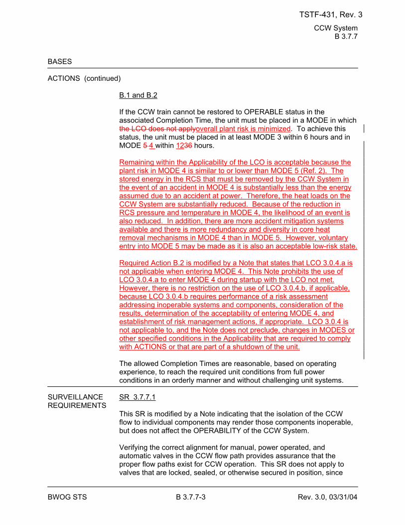
CCW System B 3.7.7
BWOG STS B 3.7.7-3 Rev. 3.0, 03/31/04
BASES ACTIONS (continued)
B.1 and B.2 If the CCW train cannot be restored to OPERABLE status in the associated Completion Time, the unit must be placed in a MODE in which the LCO does not applyoverall plant risk is minimized. To achieve this status, the unit must be placed in at least MODE 3 within 6 hours and in MODE 5 4 within 1236 hours. Remaining within the Applicability of the LCO is acceptable because the plant risk in MODE 4 is similar to or lower than MODE 5 (Ref. 2). The stored energy in the RCS that must be removed by the CCW System in the event of an accident in MODE 4 is substantially less than the energy assumed due to an accident at power. Therefore, the heat loads on the CCW System are substantially reduced. Because of the reduction in RCS pressure and temperature in MODE 4, the likelihood of an event is also reduced. In addition, there are more accident mitigation systems available and there is more redundancy and diversity in core heat removal mechanisms in MODE 4 than in MODE 5. However, voluntary entry into MODE 5 may be made as it is also an acceptable low-risk state. Required Action B.2 is modified by a Note that states that LCO 3.0.4.a is not applicable when entering MODE 4. This Note prohibits the use of LCO 3.0.4.a to enter MODE 4 during startup with the LCO not met. However, there is no restriction on the use of LCO 3.0.4.b, if applicable, because LCO 3.0.4.b requires performance of a risk assessment addressing inoperable systems and components, consideration of the results, determination of the acceptability of entering MODE 4, and establishment of risk management actions, if appropriate. LCO 3.0.4 is not applicable to, and the Note does not preclude, changes in MODES or other specified conditions in the Applicability that are required to comply with ACTIONS or that are part of a shutdown of the unit. The allowed Completion Times are reasonable, based on operating experience, to reach the required unit conditions from full power conditions in an orderly manner and without challenging unit systems.
SURVEILLANCE SR 3.7.7.1 REQUIREMENTS
This SR is modified by a Note indicating that the isolation of the CCW flow to individual components may render those components inoperable, but does not affect the OPERABILITY of the CCW System. Verifying the correct alignment for manual, power operated, and automatic valves in the CCW flow path provides assurance that the proper flow paths exist for CCW operation. This SR does not apply to valves that are locked, sealed, or otherwise secured in position, since
TSTF-431, Rev. 3
CCW System B 3.7.7
BWOG STS B 3.7.7-5 Rev. 3.0, 03/31/04
BASES SURVEILLANCE REQUIREMENTS (continued)
controls. The [18] month Frequency is based on the need to perform this Surveillance under the conditions that apply during a plant outage and the potential for an unplanned transient if the Surveillance were performed with the reactor at power. Operating experience has shown that these components usually pass the Surveillance when performed at the [18] month Frequency. Therefore, the Frequency is acceptable from a reliability standpoint. SR 3.7.7.3 This SR verifies proper automatic operation of the CCW pumps on an actual or simulated actuation signal. The CCW System is a normally operating system that cannot be fully actuated as part of routine testing during normal operation. The [18] month Frequency is based on the need to perform this Surveillance under the conditions that apply during a plant outage and the potential for an unplanned transient if the Surveillance were performed with the reactor at power. Operating experience has shown that these components usually pass the Surveillance when performed at the [18] month Frequency. Therefore, the Frequency is acceptable from a reliability standpoint.
REFERENCES 1. FSAR, Section [9.2.2]. 2. BAW-2441-A, Revision 2, Risk Informed Justification for LCO End-
State Changes, September 2006.
TSTF-431, Rev. 3
SWS B 3.7.8
BWOG STS B 3.7.8-3 Rev. 3.0, 03/31/04
BASES ACTIONS (continued)
OPERABLE SWS train could result in loss of SWS function. Required Action A.1 is modified by two Notes. The first Note indicates that the applicable Conditions and Required Actions of LCO 3.8.1, "AC Sources - Operating," should be entered if an inoperable SWS train results in an inoperable EDG. The second Note indicates that the applicable Conditions and Required Actions of LCO 3.4.6, "RCS Loops - MODE 4," should be entered if an inoperable SWS train results in an inoperable DHR train. The 72 hour Completion Time is based on the redundant capabilities afforded by the OPERABLE train, and the low probability of a DBA occurring during this period. B.1 and B.2 If the SWS train cannot be restored to OPERABLE status within the associated Completion Time, the unit must be placed in a MODE in which the LCO does not applyoverall plant risk is minimized. To achieve this status, the unit must be placed in at least MODE 3 within 6 hours, and in MODE 45 within 1236 hours. Remaining within the Applicability of the LCO is acceptable because the plant risk in MODE 4 is similar to or lower than MODE 5 (Ref. 4). The stored energy in the RCS that must be removed by the SWS in the event of an accident in MODE 4 is substantially less than the energy assumed due to an accident at power. Therefore, the heat loads on the SWS are substantially reduced. Because of the reduction in RCS pressure and temperature in MODE 4, the likelihood of an event is also reduced. In addition, there are more accident mitigation systems available and there is more redundancy and diversity in core heat removal mechanisms in MODE 4 than in MODE 5. However, voluntary entry into MODE 5 may be made as it is also an acceptable low-risk state. Required Action B.2 is modified by a Note that states that LCO 3.0.4.a is not applicable when entering MODE 4. This Note prohibits the use of LCO 3.0.4.a to enter MODE 4 during startup with the LCO not met. However, there is no restriction on the use of LCO 3.0.4.b, if applicable, because LCO 3.0.4.b requires performance of a risk assessment addressing inoperable systems and components, consideration of the results, determination of the acceptability of entering MODE 4, and establishment of risk management actions, if appropriate. LCO 3.0.4 is not applicable to, and the Note does not preclude, changes in MODES or other specified conditions in the Applicability that are required to comply with ACTIONS or that are part of a shutdown of the unit.
TSTF-431, Rev. 3
SWS B 3.7.8
BWOG STS B 3.7.8-5 Rev. 3.0, 03/31/04
BASES SURVEILLANCE REQUIREMENTS (continued)
SR 3.7.8.2 The SR verifies proper automatic operation of the SWS valves. The SWS is a normally operating system that cannot be fully actuated as part of the normal testing. This SR is not required for valves that are locked, sealed, or otherwise secured in position under administrative controls. The [18] month Frequency is based on the need to perform this Surveillance under the conditions that apply during a unit outage and the potential for an unplanned transient if the Surveillance were performed with the reactor at power. Operating experience has shown that these components usually pass the Surveillance when performed at the [18] month Frequency. Therefore, the Frequency is acceptable from a reliability standpoint. SR 3.7.8.3 The SR verifies proper automatic operation of the SWS pumps on an actual or simulated actuation signal. The SWS is a normally operating system that cannot be fully actuated as part of normal testing during normal operation. The [18] month Frequency is based on the need to perform this Surveillance under the conditions that apply during a unit outage and the potential for an unplanned transient if the Surveillance were performed with the reactor at power. Operating experience has shown that these components usually pass the Surveillance when performed at an [18] month Frequency. Therefore, the Frequency is acceptable from a reliability standpoint.
REFERENCES 1. FSAR, Section [9.2.1]. 2. FSAR, Section [6.2]. 3. FSAR, Section [6.3]. 4. BAW-2441-A, Revision 2, Risk Informed Justification for LCO End-
State Changes, September 2006.
TSTF-431, Rev. 3
UHS B 3.7.9
BWOG STS B 3.7.9-2 Rev. 3.0, 03/31/04
BASES APPLICABLE The UHS is the sink for heat removal from the reactor core following all SAFETY accidents and anticipated operational occurrences in which the unit is ANALYSES cooled down and placed on [decay heat removal]. Its maximum post
accident heat load occurs approximately 20 minutes after a design basis loss of coolant accident (LOCA). Near this time, the unit switches from injection to recirculation and the containment cooling systems are required to remove the core decay heat. The operating limits are based on conservative heat transfer analyses for the worst case LOCA. Reference 1 provides the details of the assumptions used in the analysis. These assumptions include: worst expected meteorological conditions, conservative uncertainties when calculating decay heat, and the worst case failure (e.g., single failure of a manmade structure). The UHS is designed in accordance with Regulatory Guide 1.27 (Ref. 2), which requires a 30 day supply of cooling water in the UHS. The UHS satisfies Criterion 3 of 10 CFR 50.36(c)(2)(ii).
LCO The UHS is required to be OPERABLE and is considered OPERABLE if
[it contains a sufficient volume of water at or below the maximum temperature] that would allow the SWS to operate for at least 30 days following the design basis LOCA without the loss of net positive suction head (NPSH), and without exceeding the maximum design temperature of the equipment served by the SWS. To meet this condition, the UHS temperature should not exceed [90]°F, and the level should not fall below [562] ft [mean sea level] during normal unit operation.
APPLICABILITY In MODES 1, 2, 3, and 4, the UHS is a normally operating system that is
required to support the OPERABILITY of the equipment serviced by the UHS and is required to be OPERABLE in these MODES.
In MODES 5 and 6, the OPERABILITY requirements of the UHS are determined by the systems it supports.
ACTIONS [ A.1
If one or more cooling towers have one fan inoperable (i.e., at least up to one fan per cooling tower is OPERABLEinoperable), action must be taken to restore the inoperable cooling tower fan(s) to OPERABLE status within 7 days. The 7 day Completion Time is reasonable, based on the low probability of an accident occurring during the 7 days that one cooling tower fan is inoperable in one or more cooling towers, the number of available systems, and the time required to complete the Required Action. ]
TSTF-431, Rev. 3
UHS B 3.7.9
BWOG STS B 3.7.9-3 Rev. 3.0, 03/31/04
BASES ACTIONS (continued)
B.1 and B.2 If the cooling tower fan cannot be restored to OPERABLE status within the associated Completion Time, the plant must be brought to a MODE in which overall plant risk is minimized. To achieve this status, the plant must be brought to MODE 3 within 6 hours and to MODE 4 within 12 hours. Remaining within the Applicability of the LCO is acceptable because the plant risk in MODE 4 is similar to or lower than MODE 5 (Ref. 3). The stored energy in the RCS that must be removed by the UHS in the event of an accident in MODE 4 is substantially less than the energy assumed due to an accident at power. Therefore, the heat load on the UHS is substantially reduced. Because of the reduction in RCS pressure and temperature in MODE 4, the likelihood of an event is also reduced. In addition, there are more accident mitigation systems available and there is more redundancy and diversity in core heat removal mechanisms in MODE 4 than in MODE 5. However, voluntary entry into MODE 5 may be made as it is also an acceptable low-risk state. Required Action B.2 is modified by a Note that states that LCO 3.0.4.a is not applicable when entering MODE 4. This Note prohibits the use of LCO 3.0.4.a to enter MODE 4 during startup with the LCO not met. However, there is no restriction on the use of LCO 3.0.4.b, if applicable, because LCO 3.0.4.b requires performance of a risk assessment addressing inoperable systems and components, consideration of the results, determination of the acceptability of entering MODE 4, and establishment of risk management actions, if appropriate. LCO 3.0.4 is not applicable to, and the Note does not preclude, changes in MODES or other specified conditions in the Applicability that are required to comply with ACTIONS or that are part of a shutdown of the unit.
[ BC.1 -----------------------------------REVIEWER’S NOTE----------------------------------- The [ ]°F is the maximum allowed UHS temperature value and is based on temperature limitations of the equipment that is relied upon for accident mitigation and safe shutdown of the unit. -------------------------------------------------------------------------------------------------- With water temperature of the UHS > [90]°F, the design basis assumption associated with initial UHS temperature is bounded provided the temperature of the UHS averaged over the previous 24 hour period is ≥ [90]°F. With the water temperature of the UHS > [90]°F, long term cooling capability of the ECCS loads and DGs may be affected.
TSTF-431, Rev. 3
UHS B 3.7.9
BWOG STS B 3.7.9-4 Rev. 3.0, 03/31/04
Therefore, to ensure long term cooling capability is provided to the ECCS loads when water temperature of the UHS is > [90]°F, Required Action CB.1 is provided to more frequently monitor the water temperature of the UHS and verify the temperature is ≤ [90]°F when averaged over the previous 24 hour period. The once per hour Completion Time takes into consideration UHS temperature variations and the increased monitoring frequency needed to ensure design basis assumptions and equipment limitations are not exceeded in this condition. If the water temperature of the UHS exceeds [90]°F when averaged over the previous 24 hour period or the water temperature of the UHS exceeds [ ]°F, Condition DC must be entered immediately.]
[ DC.1 and DC.2 If the Required Actions and Completion Time of Condition C[A or B] are not met, or the UHS is inoperable [for reasons other than Condition A or CB], the unit must be placed in a MODE in which the LCO does not apply. To achieve this status, the unit must be placed in at least MODE 3 within 6 hours and in MODE 5 within 36 hours. The allowed Completion Times are reasonable, based on operating experience, to reach the required unit conditions from full power conditions in an orderly manner and without challenging unit systems. ]
SURVEILLANCE [ SR 3.7.9.1 REQUIREMENTS
This SR verifies that adequate long term (30 days) cooling can be maintained. The level specified also ensures NPSH is available for operating the SWS pumps. The 24 hour Frequency is based on operating experience related to the trending of the parameter variations during the applicable MODES. This SR verifies that the UHS water level is ≥ [ ] ft [mean sea level]. ]
TSTF-431, Rev. 3
UHS B 3.7.9
BWOG STS B 3.7.9-5 Rev. 3.0, 03/31/04
BASES SURVEILLANCE REQUIREMENTS (continued)
[ SR 3.7.9.2 This SR verifies that the SWS can cool the CCW System to at least its maximum design temperature within the maximum [ accident or normal heat loads for 30 days following a Design Basis Accident. The 24 hour Frequency is based on operating experience related to the trending of the parameter variations during the applicable MODES. This SR verifies that the UHS average water temperature is ≤ [90]°F. ]
[ SR 3.7.9.3 Operating each cooling tower fan for ≥ [15] minutes ensures that all fans are OPERABLE and that all associated controls are functioning properly. It also ensures that fan or motor failure, or excessive vibration, can be detected for corrective action. The 31 day Frequency is based on operating experience, known reliability of the fan units, the redundancy available, and the low probability of significant degradation of the UHS cooling tower fans occurring between surveillances. ]
REFERENCES 1. FSAR, Section [9.2.5]. 2. Regulatory Guide 1.27. 3. BAW-2441-A, Revision 2, Risk Informed Justification for LCO End-
State Changes, September 2006.
TSTF-431, Rev. 3
CREVS B 3.7.10
BWOG STS B 3.7.10-3 Rev. 3.0, 03/31/04
BASES ACTIONS A.1
With one CREVS train inoperable, action must be taken to restore OPERABLE status within 7 days. In this Condition, the remaining OPERABLE CREVS train is adequate to perform the control room radiation protection function. However, the overall reliability is reduced because a failure in the OPERABLE CREVS train could result in loss of CREVS function. The 7 day Completion Time is based on the low probability of a DBA occurring during this time period, and ability of the remaining train to provide the required capability. B.1 -----------------------------------REVIEWER’S NOTE----------------------------------- Adoption of Condition B is dependent on a commitment from the licensee to have written procedures available describing compensatory measures to be taken in the event of an intentional or unintentional entry into Condition B. -------------------------------------------------------------------------------------------------- If the control room boundary is inoperable in MODE 1, 2, 3, or 4, the CREVS trains cannot perform their intended functions. Actions must be taken to restore an OPERABLE control room boundary within 24 hours. During the period that the control room boundary is inoperable, appropriate compensatory measures (consistent with the intent of GDC 19) should be utilized to protect control room operators from potential hazards such as radioactive contamination, toxic chemicals, smoke, temperature and relative humidity, and physical security. Preplanned measures should be available to address these concerns for intentional and unintentional entry into the condition. The 24 hour Completion Time is reasonable based on the low probability of a DBA occurring during this time period, and the use of compensatory measures. The 24 hour Completion Time is a typically reasonable time to diagnose, plan and possibly repair, and test most problems with the control room boundary. C.1 and C.2 In MODE 1, 2, 3, or 4, if the inoperable CREVS train or control room boundary cannot be restored to OPERABLE status within the required Completion Time, the unit must be placed in a MODE in which the LCO does not applyoverall plant risk is minimized. To achieve this status, the unit must be placed in at least MODE 3 within 6 hours, and in MODE 45 within 1236 hours. Remaining within the Applicability of the LCO is acceptable because the plant risk in MODE 4 is similar to or lower than MODE 5 (Ref. 3). The
TSTF-431, Rev. 3
CREVS B 3.7.10
BWOG STS B 3.7.10-4 Rev. 3.0, 03/31/04
control room is isolated and the CREVS is utilized in the event of an accident, such as a loss of coolant accident, to reduce or eliminate the ingress of radioactive material released during the event into the control room. Because of the reduction in RCS pressure and temperature in MODE 4, the likelihood of an accident is reduced. In addition, there are more accident mitigation systems available and there is more redundancy and diversity in core heat removal mechanisms in MODE 4 than in MODE 5. However, voluntary entry into MODE 5 may be made as it is also an acceptable low-risk state. Required Action C.2 is modified by a Note that states that LCO 3.0.4.a is not applicable when entering MODE 4. This Note prohibits the use of LCO 3.0.4.a to enter MODE 4 during startup with the LCO not met. However, there is no restriction on the use of LCO 3.0.4.b, if applicable, because LCO 3.0.4.b requires performance of a risk assessment addressing inoperable systems and components, consideration of the results, determination of the acceptability of entering MODE 4, and establishment of risk management actions, if appropriate. LCO 3.0.4 is not applicable to, and the Note does not preclude, changes in MODES or other specified conditions in the Applicability that are required to comply with ACTIONS or that are part of a shutdown of the unit. The allowed Completion Times are reasonable, based on operating experience, to reach the required unit conditions from full power conditions in an orderly manner and without challenging unit systems.
TSTF-431, Rev. 3
CREVS B 3.7.10
BWOG STS B 3.7.10-6 Rev. 3.0, 03/31/04
BASES SURVEILLANCE SR 3.7.10.1 REQUIREMENTS
Standby systems should be checked periodically to ensure that they function properly. As the environment and normal operating conditions on this system are not severe, testing each train once every month adequately checks this system. Monthly heater operations dry out any moisture that has accumulated in the charcoal because of humidity in the ambient air. [Systems with heaters must be operated for ≥ 10 continuous hours with the heaters energized. Systems without heaters need only be operated for ≥ 15 minutes to demonstrate the function of the system.] The 31 day Frequency is based on the known reliability of the equipment and the two train redundancy available. SR 3.7.10.2 This SR verifies that the required CREVS testing is performed in accordance with the [Ventilation Filter Testing Program (VFTP)]. The [VFTP] includes testing HEPA filter performance, charcoal absorber efficiency, minimum system flow rate, and the physical properties of the activated charcoal. Specific test frequencies and additional information are discussed in detail in the [VFTP]. SR 3.7.10.3 This SR verifies that [each CREVS train starts] [or the control room isolates] and operates on an actual or simulated actuation signal. The Frequency of [18] months is consistent with that specified in Reference 43. SR 3.7.10.4 This SR verifies the integrity of the control room enclosure and the assumed inleakage rates of the potentially contaminated air. The control room positive pressure, with respect to potentially contaminated adjacent areas, is periodically tested to verify that the CREVS is functioning properly. During the emergency mode of operation, the CREVS is designed to pressurize the control room ≥ [0.125] inches water gauge positive pressure, with respect to adjacent areas, to prevent unfiltered inleakage. The CREVS is designed to maintain this positive pressure with one train at a flow rate of ≤ [3300] cfm. This value includes [300] cfm of outside air. The Frequency of [18] months on a STAGGERED TEST BASIS is consistent with industry practice and other filtration SRs.
TSTF-431, Rev. 3
CREVS B 3.7.10
BWOG STS B 3.7.10-7 Rev. 3.0, 03/31/04
BASES REFERENCES 1. FSAR, Section [9.4]. 2. FSAR, Chapter [15]. 3. BAW-2441-A, Revision 2, Risk Informed Justification for LCO End-
State Changes, September 2006. 43. Regulatory Guide 1.52, Rev. [2].
TSTF-431, Rev. 3
CREATCS B 3.7.11
BWOG STS B 3.7.11-2 Rev. 3.0, 03/31/04
BASES LCO Two independent and redundant trains of the CREATCS are required to
be OPERABLE to ensure that at least one is available, assuming a single failure disables the other train. Total system failure could result in the equipment operating temperature exceeding limits in the event of an accident. The CREATCS is considered OPERABLE when the individual components that are necessary to maintain control room temperature are OPERABLE in both trains. These components include the cooling coils, water cooled condensing units, and associated temperature control instrumentation. In addition, the CREATCS must be OPERABLE to the extent that air circulation can be maintained.
APPLICABILITY In MODES 1, 2, 3, 4, [5, and 6,] and during movement of [recently]
irradiated fuel assemblies [i.e., fuel that has occupied part of a critical reactor core within the previous [X] days)], the CREATCS must be OPERABLE to ensure that the control room temperature will not exceed equipment OPERABILITY requirements following isolation of the control room.
ACTIONS A.1
With one CREATCS train inoperable, action must be taken to restore OPERABLE status within 30 days. In this Condition, the remaining OPERABLE CREATCS train is adequate to maintain the control room temperature within limits. However, the overall reliability is reduced because a failure in the OPERABLE CREATCS train could result in a loss of CREATCS function. The 30 day Completion Time is based on the low probability of an event occurring requiring control room isolation, the consideration that the remaining train can provide the required capabilities, and the alternate safety or nonsafety related cooling means that are available. Concurrent failure of two CREATCS trains would result in the loss of function capability; therefore, LCO 3.0.3 must be entered immediately. B.1 and B.2 In MODE 1, 2, 3, or 4, if the inoperable CREATCS train cannot be restored to OPERABLE status within the required Completion Time, the unit must be placed in a MODE in which the LCO does not applyoverall plant risk is minimized. To achieve this status, the unit must be placed in at least MODE 3 within 6 hours, and in MODE 45 within 1236 hours. Remaining within the Applicability of the LCO is acceptable because the plant risk in MODE 4 is similar to or lower than MODE 5 (Ref. 2). The control room is isolated in the event of an accident, such as a loss of
TSTF-431, Rev. 3

CREATCS B 3.7.11
BWOG STS B 3.7.11-3 Rev. 3.0, 03/31/04
coolant accident, to reduce or eliminate the ingress of radioactive material released during the event into the control room. However, control room ambient temperatures may increase as a result of operating in this manner. The CREATCS mitigates this temperature rise. Because of the reduction in RCS pressure and temperature in MODE 4, the likelihood of an accident is also reduced. In addition, there are more accident mitigation systems available and there is more redundancy and diversity in core heat removal mechanisms in MODE 4 than in MODE 5. However, voluntary entry into MODE 5 may be made as it is also an acceptable low-risk state. Required Action B.2 is modified by a Note that states that LCO 3.0.4.a is not applicable when entering MODE 4. This Note prohibits the use of LCO 3.0.4.a to enter MODE 4 during startup with the LCO not met. However, there is no restriction on the use of LCO 3.0.4.b, if applicable, because LCO 3.0.4.b requires performance of a risk assessment addressing inoperable systems and components, consideration of the results, determination of the acceptability of entering MODE 4, and establishment of risk management actions, if appropriate. LCO 3.0.4 is not applicable to, and the Note does not preclude, changes in MODES or other specified conditions in the Applicability that are required to comply with ACTIONS or that are part of a shutdown of the unit. The allowed Completion Times are reasonable, based on operating experience, to reach the required unit conditions from full power conditions in an orderly manner without challenging unit systems.
TSTF-431, Rev. 3
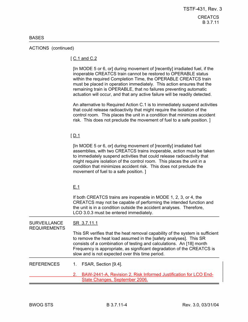
CREATCS B 3.7.11
BWOG STS B 3.7.11-4 Rev. 3.0, 03/31/04
BASES ACTIONS (continued)
[ C.1 and C.2 [In MODE 5 or 6, or] during movement of [recently] irradiated fuel, if the inoperable CREATCS train cannot be restored to OPERABLE status within the required Completion Time, the OPERABLE CREATCS train must be placed in operation immediately. This action ensures that the remaining train is OPERABLE, that no failures preventing automatic actuation will occur, and that any active failure will be readily detected. An alternative to Required Action C.1 is to immediately suspend activities that could release radioactivity that might require the isolation of the control room. This places the unit in a condition that minimizes accident risk. This does not preclude the movement of fuel to a safe position. ]
[ D.1 [In MODE 5 or 6, or] during movement of [recently] irradiated fuel assemblies, with two CREATCS trains inoperable, action must be taken to immediately suspend activities that could release radioactivity that might require isolation of the control room. This places the unit in a condition that minimizes accident risk. This does not preclude the movement of fuel to a safe position. ] E.1 If both CREATCS trains are inoperable in MODE 1, 2, 3, or 4, the CREATCS may not be capable of performing the intended function and the unit is in a condition outside the accident analyses. Therefore, LCO 3.0.3 must be entered immediately.
SURVEILLANCE SR 3.7.11.1 REQUIREMENTS
This SR verifies that the heat removal capability of the system is sufficient to remove the heat load assumed in the [safety analyses]. This SR consists of a combination of testing and calculations. An [18] month Frequency is appropriate, as significant degradation of the CREATCS is slow and is not expected over this time period.
REFERENCES 1. FSAR, Section [9.4]. 2. BAW-2441-A, Revision 2, Risk Informed Justification for LCO End-
State Changes, September 2006.
TSTF-431, Rev. 3
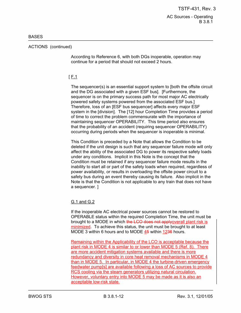
AC Sources - Operating B 3.8.1
BWOG STS B 3.8.1-12 Rev. 3.1, 12/01/05
BASES ACTIONS (continued)
According to Reference 6, with both DGs inoperable, operation may continue for a period that should not exceed 2 hours.
[ F.1 The sequencer(s) is an essential support system to [both the offsite circuit and the DG associated with a given ESF bus]. [Furthermore, the sequencer is on the primary success path for most major AC electrically powered safety systems powered from the associated ESF bus.] Therefore, loss of an [ESF bus sequencer] affects every major ESF system in the [division]. The [12] hour Completion Time provides a period of time to correct the problem commensurate with the importance of maintaining sequencer OPERABILITY. This time period also ensures that the probability of an accident (requiring sequencer OPERABILITY) occurring during periods when the sequencer is inoperable is minimal. This Condition is preceded by a Note that allows the Condition to be deleted if the unit design is such that any sequencer failure mode will only affect the ability of the associated DG to power its respective safety loads under any conditions. Implicit in this Note is the concept that the Condition must be retained if any sequencer failure mode results in the inability to start all or part of the safety loads when required, regardless of power availability, or results in overloading the offsite power circuit to a safety bus during an event thereby causing its failure. Also implicit in the Note is that the Condition is not applicable to any train that does not have a sequencer. ] G.1 and G.2 If the inoperable AC electrical power sources cannot be restored to OPERABLE status within the required Completion Time, the unit must be brought to a MODE in which the LCO does not applyoverall plant risk is minimized. To achieve this status, the unit must be brought to at least MODE 3 within 6 hours and to MODE 45 within 1236 hours. Remaining within the Applicability of the LCO is acceptable because the plant risk in MODE 4 is similar to or lower than MODE 5 (Ref. 8). There are more accident mitigation systems available and there is more redundancy and diversity in core heat removal mechanisms in MODE 4 than in MODE 5. In particular, in MODE 4 the turbine-driven emergency feedwater pump[s] are available following a loss of AC sources to provide RCS cooling via the steam generators utilizing natural circulation. However, voluntary entry into MODE 5 may be made as it is also an acceptable low-risk state.
TSTF-431, Rev. 3
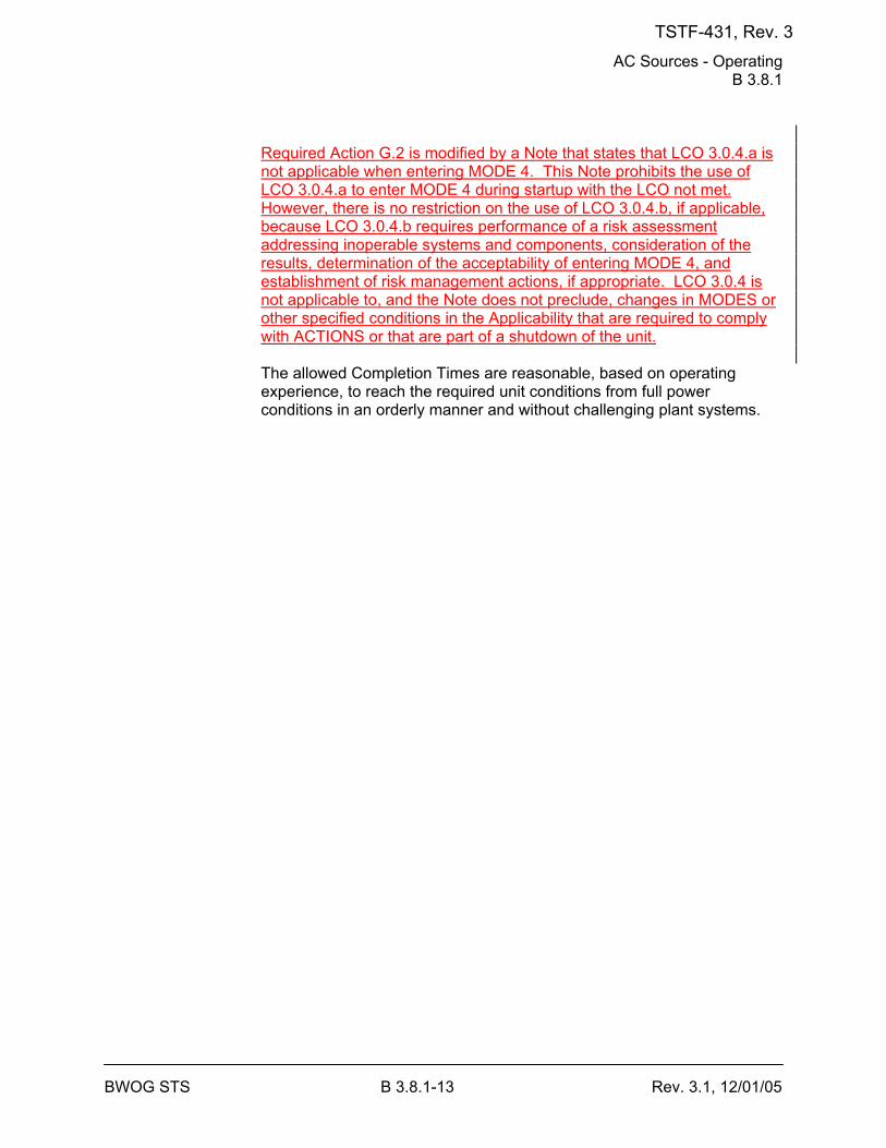
AC Sources - Operating B 3.8.1
BWOG STS B 3.8.1-13 Rev. 3.1, 12/01/05
Required Action G.2 is modified by a Note that states that LCO 3.0.4.a is not applicable when entering MODE 4. This Note prohibits the use of LCO 3.0.4.a to enter MODE 4 during startup with the LCO not met. However, there is no restriction on the use of LCO 3.0.4.b, if applicable, because LCO 3.0.4.b requires performance of a risk assessment addressing inoperable systems and components, consideration of the results, determination of the acceptability of entering MODE 4, and establishment of risk management actions, if appropriate. LCO 3.0.4 is not applicable to, and the Note does not preclude, changes in MODES or other specified conditions in the Applicability that are required to comply with ACTIONS or that are part of a shutdown of the unit. The allowed Completion Times are reasonable, based on operating experience, to reach the required unit conditions from full power conditions in an orderly manner and without challenging plant systems.
TSTF-431, Rev. 3
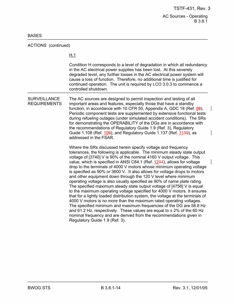
AC Sources - Operating B 3.8.1
BWOG STS B 3.8.1-14 Rev. 3.1, 12/01/05
BASES ACTIONS (continued)
H.1 Condition H corresponds to a level of degradation in which all redundancy in the AC electrical power supplies has been lost. At this severely degraded level, any further losses in the AC electrical power system will cause a loss of function. Therefore, no additional time is justified for continued operation. The unit is required by LCO 3.0.3 to commence a controlled shutdown.
SURVEILLANCE The AC sources are designed to permit inspection and testing of all REQUIREMENTS important areas and features, especially those that have a standby
function, in accordance with 10 CFR 50, Appendix A, GDC 18 (Ref. 98). Periodic component tests are supplemented by extensive functional tests during refueling outages (under simulated accident conditions). The SRs for demonstrating the OPERABILITY of the DGs are in accordance with the recommendations of Regulatory Guide 1.9 (Ref. 3), Regulatory Guide 1.108 (Ref. 109), and Regulatory Guide 1.137 (Ref. 1110), as addressed in the FSAR. Where the SRs discussed herein specify voltage and frequency tolerances, the following is applicable. The minimum steady state output voltage of [3740] V is 90% of the nominal 4160 V output voltage. This value, which is specified in ANSI C84.1 (Ref. 1211), allows for voltage drop to the terminals of 4000 V motors whose minimum operating voltage is specified as 90% or 3600 V. It also allows for voltage drops to motors and other equipment down through the 120 V level where minimum operating voltage is also usually specified as 90% of name plate rating. The specified maximum steady state output voltage of [4756] V is equal to the maximum operating voltage specified for 4000 V motors. It ensures that for a lightly loaded distribution system, the voltage at the terminals of 4000 V motors is no more than the maximum rated operating voltages. The specified minimum and maximum frequencies of the DG are 58.8 Hz and 61.2 Hz, respectively. These values are equal to ± 2% of the 60 Hz nominal frequency and are derived from the recommendations given in Regulatory Guide 1.9 (Ref. 3).
TSTF-431, Rev. 3
AC Sources - Operating B 3.8.1
BWOG STS B 3.8.1-17 Rev. 3.1, 12/01/05
BASES SURVEILLANCE REQUIREMENTS (continued)
This SR is modified by four Notes. Note 1 indicates that diesel engine runs for this Surveillance may include gradual loading, as recommended by the manufacturer, so that mechanical stress and wear on the diesel engine are minimized. Note 2 states that momentary transients because of changing bus loads do not invalidate this test. Similarly, momentary power factor transients above the limit will not invalidate the test. Note 3 indicates that this Surveillance should be conducted on only one DG at a time in order to avoid common cause failures that might result from offsite circuit or grid perturbations. Note 4 stipulates a prerequisite requirement for performance of this SR. A successful DG start must precede this test to credit satisfactory performance. SR 3.8.1.4 This SR provides verification that the level of fuel oil in the day tank [and engine mounted tank] is at or above the level at which fuel oil is automatically added. The level is expressed as an equivalent volume in gallons, and is selected to ensure adequate fuel oil for a minimum of 1 hour of DG operation at full load plus 10%. The 31 day Frequency is adequate to assure that a sufficient supply of fuel oil is available, since low level alarms are provided and unit operators would be aware of any large uses of fuel oil during this period. SR 3.8.1.5 Microbiological fouling is a major cause of fuel oil degradation. There are numerous bacteria that can grow in fuel oil and cause fouling, but all must have a water environment in order to survive. Removal of water from the fuel oil day [and engine mounted] tanks once every [31] days eliminates the necessary environment for bacterial survival. This is the most effective means of controlling microbiological fouling. In addition, it eliminates the potential for water entrainment in the fuel oil during DG operation. Water may come from any of several sources, including condensation, ground water, rain water, contaminated fuel oil, and from breakdown of the fuel oil by bacteria. Frequent checking for and removal of accumulated water minimizes fouling and provides data regarding the watertight integrity of the fuel oil system. The Surveillance Frequencies are established by Regulatory Guide 1.137 (Ref. 1110). This SR is for preventive maintenance. The presence of water does not necessarily represent failure of this SR, provided the accumulated water is removed during the performance of this Surveillance.
TSTF-431, Rev. 3
AC Sources - Operating B 3.8.1
BWOG STS B 3.8.1-18 Rev. 3.1, 12/01/05
BASES SURVEILLANCE REQUIREMENTS (continued)
SR 3.8.1.6 This Surveillance demonstrates that each required fuel oil transfer pump operates and transfers fuel oil from its associated storage tank to its associated day tank. This is required to support continuous operation of standby power sources. This Surveillance provides assurance that the fuel oil transfer pump is OPERABLE, the fuel oil piping system is intact, the fuel delivery piping is not obstructed, and the controls and control systems for automatic fuel transfer systems are OPERABLE.
[ The Frequency for this SR is variable, depending on individual system design, with up to a [92] day interval. The [92] day Frequency corresponds to the testing requirements for pumps as contained in the ASME Code (Ref. 1312); however, the design of fuel transfer systems is such that pumps will operate automatically or must be started manually in order to maintain an adequate volume of fuel oil in the day [and engine mounted] tanks during or following DG testing. In such a case, a 31 day Frequency is appropriate. Since proper operation of fuel transfer systems is an inherent part of DG OPERABILITY, the Frequency of this SR should be modified to reflect individual designs. ] SR 3.8.1.7 See SR 3.8.1.2.
[ SR 3.8.1.8 Transfer of each [4.16 kV ESF bus] power supply from the normal offsite circuit to the alternate offsite circuit demonstrates the OPERABILITY of the alternate circuit distribution network to power the shutdown loads. The [18 month] Frequency of the Surveillance is based on engineering judgment, taking into consideration the unit conditions required to perform the Surveillance, and is intended to be consistent with expected fuel cycle lengths. Operating experience has shown that these components usually pass the SR when performed at the [18 month] Frequency. Therefore, the Frequency was concluded to be acceptable from a reliability standpoint.
TSTF-431, Rev. 3
AC Sources - Operating B 3.8.1
BWOG STS B 3.8.1-20 Rev. 3.1, 12/01/05
BASES SURVEILLANCE REQUIREMENTS (continued)
b. Tripping its associated single largest post-accident load with the DG
solely supplying the bus. As required by IEEE-308 (Ref. 1413), the load rejection test is acceptable if the increase in diesel speed does not exceed 75% of the difference between synchronous speed and the overspeed trip setpoint, or 15% above synchronous speed, whichever is lower. The time, voltage, and frequency tolerances specified in this SR are derived from Regulatory Guide 1.9 (Ref. 3) recommendations for response during load sequence intervals. The [3] seconds specified is equal to 60% of a typical 5 second load sequence interval associated with sequencing of the largest load. The voltage and frequency specified are consistent with the design range of the equipment powered by the DG. SR 3.8.1.9.a corresponds to the maximum frequency excursion, while SR 3.8.1.9.b and SR 3.8.1.9.c are steady state voltage and frequency values to which the system must recover to following load rejection. The [18 month] Frequency is consistent with the recommendation of Regulatory Guide 1.108 (Ref. 109). This SR is modified by two Notes. The reason for Note 1 is that during operation with the reactor critical, performance of this SR could cause perturbations to the electrical distribution systems that could challenge continued steady state operation and, as a result, unit safety systems. This restriction from normally performing the Surveillance in MODE 1 or 2 is further amplified to allow the Surveillance to be performed for the purpose of reestablishing OPERABILITY (e.g., post work testing following corrective maintenance, corrective modification, deficient or incomplete surveillance testing, and other unanticipated OPERABILITY concerns) provided an assessment determines plant safety is maintained or enhanced. This assessment shall, as a minimum, consider the potential outcomes and transients associated with a failed Surveillance, a successful Surveillance, and a perturbation of the offsite or onsite system when they are tied together or operated independently for the Surveillance; as well as the operator procedures available to cope with these outcomes. These shall be measured against the avoided risk of a plant shutdown and startup to determine that plant safety is maintained or enhanced when the Surveillance is performed in MODE 1 or 2. Risk insights or deterministic methods may be used for this assessment. Credit may be taken for unplanned events that satisfy this SR. Note 2
TSTF-431, Rev. 3
AC Sources - Operating B 3.8.1
BWOG STS B 3.8.1-22 Rev. 3.1, 12/01/05
BASES SURVEILLANCE REQUIREMENTS (continued)
SR 3.8.1.10 This Surveillance demonstrates the DG capability to reject a full load without overspeed tripping or exceeding the predetermined voltage limits. The DG full load rejection may occur because of a system fault or inadvertent breaker tripping. This Surveillance ensures proper engine generator load response under the simulated test conditions. This test simulates the loss of the total connected load that the DG experiences following a full load rejection and verifies that the DG will not trip upon loss of the load. These acceptance criteria provide DG damage protection. While the DG is not expected to experience this transient during an event and continues to be available, this response ensures that the DG is not degraded for future application, including reconnection to the bus if the trip initiator can be corrected or isolated. The [18 month] Frequency is consistent with the recommendation of Regulatory Guide 1.108 (Ref. 109) and is intended to be consistent with expected fuel cycle lengths. This SR is modified by two Notes. The reason for Note 1 is that during operation with the reactor critical, performance of this SR could cause perturbation to the electrical distribution systems that could challenge continued steady state operation and, as a result, unit safety systems. This restriction from normally performing the Surveillance in MODE 1 or 2 is further amplified to allow the Surveillance to be performed for the purpose of reestablishing OPERABILITY (e.g., post work testing following corrective maintenance, corrective modification, deficient or incomplete surveillance testing, and other unanticipated OPERABILITY concerns) provided an assessment determines plant safety is maintained or enhanced. This assessment shall, as a minimum, consider the potential outcomes and transients associated with a failed Surveillance, a successful Surveillance, and a perturbation of the offsite or onsite system when they are tied together or operated independently for the Surveillance; as well as the operator procedures available to cope with these outcomes. These shall be measured against the avoided risk of a plant shutdown and startup to determine that plant safety is maintained or enhanced when the Surveillance is performed in MODE 1 or 2. Risk insights or deterministic methods may be used for this assessment. Credit may be taken for unplanned events that satisfy this SR.
TSTF-431, Rev. 3
AC Sources - Operating B 3.8.1
BWOG STS B 3.8.1-23 Rev. 3.1, 12/01/05
BASES SURVEILLANCE REQUIREMENTS (continued)
Note 2 ensures that the DG is tested under load conditions that are as close to design basis conditions as possible. When synchronized with offsite power, testing should be performed at a power factor of ≤ [0.9]. This power factor is representative of the actual inductive loading a DG would see under design basis accident conditions. Under certain conditions, however, Note 2 allows the Surveillance to be conducted at a power factor other than ≤ [0.9]. These conditions occur when grid voltage is high, and the additional field excitation needed to get the power factor to ≤ [0.9] results in voltages on the emergency busses that are too high. Under these conditions, the power factor should be maintained as close as practicable to [0.9] while still maintaining acceptable voltage limits on the emergency busses. In other circumstances, the grid voltage may be such that the DC excitation levels needed to obtain a power factor of [0.9] may not cause unacceptable voltages on the emergency busses, but the excitation levels are in excess of those recommended for the DC. In such cases, the power factor shall be maintained as close as practicable to [0.9] without exceeding the DG excitation limits. -----------------------------------REVIEWER’S NOTE----------------------------------- The above MODE restrictions may be deleted if it can be demonstrated to the staff, on a plant specific basis, that performing the SR with the reactor in any of the restricted MODES can satisfy the following criteria, as applicable: a. Performance of the SR will not render any safety system or
component inoperable, b. Performance of the SR will not cause perturbations to any of the
electrical distribution systems that could result in a challenge to steady state operation or to plant safety systems, and
c. Performance of the SR, or failure of the SR, will not cause, or result
in, an AOO with attendant challenge to plant safety systems. -------------------------------------------------------------------------------------------------- SR 3.8.1.11 As required by Regulatory Guide 1.108 (Ref. 109), paragraph 2.a.(1), this Surveillance demonstrates the as designed operation of the standby power sources during loss of the offsite source. This test verifies all actions encountered from the loss of offsite power, including shedding of the non-essential loads and energization of the emergency buses and respective loads from the DG. It further demonstrates the capability of the DG to automatically achieve the required voltage and frequency within the specified time.
TSTF-431, Rev. 3
AC Sources - Operating B 3.8.1
BWOG STS B 3.8.1-24 Rev. 3.1, 12/01/05
BASES SURVEILLANCE REQUIREMENTS (continued)
The DG auto-start time of [10] seconds is derived from requirements of the accident analysis to respond to a design basis large break LOCA. The Surveillance should be continued for a minimum of 5 minutes in order to demonstrate that all starting transients have decayed and stability has been achieved. The requirement to verify the connection and power supply of permanent and auto-connected loads is intended to satisfactorily show the relationship of these loads to the DG loading logic. In certain circumstances, many of these loads can not actually be connected or loaded without undue hardship or potential for undesired operation. For instance, Emergency Core Cooling Systems (ECCS) injection valves are not desired to be stroked open, high pressure injection systems are not capable of being operated at full flow, or decay heat removal (DHR) systems performing a DHR function are not desired to be realigned to the ECCS mode of operation. In lieu of actual demonstration of connection and loading of loads, testing that adequately shows the capability of the DG system to perform these functions is acceptable. This testing may include any series of sequential, overlapping, or total steps so that the entire connection and loading sequence is verified. The Frequency of [18 months] is consistent with the recommendations of Regulatory Guide 1.108 (Ref. 109), paragraph 2.a.(1), takes into consideration unit conditions required to perform the Surveillance, and is intended to be consistent with expected fuel cycle lengths. This SR is modified by two Notes. The reason for Note 1 is to minimize wear and tear on the DGs during testing. For the purpose of this testing, the DGs must be started from standby conditions, that is, with the engine coolant and oil continuously circulated and temperature maintained consistent with manufacturer recommendations. The reason for Note 2 is that performing the Surveillance would remove a required offsite circuit from service, perturb the electrical distribution system, and challenge safety systems. This restriction from normally performing the Surveillance in MODE 1 or 2 is further amplified to allow portions of the Surveillance to be performed for the purpose of reestablishing OPERABILITY (e.g., post work testing following corrective maintenance, corrective modification, deficient or incomplete surveillance testing, and other unanticipated OPERABILITY concerns) provided an assessment determines plant safety is maintained or enhanced. This assessment shall, as a minimum, consider the potential outcomes and transients associated with a failed partial Surveillance, a successful partial
TSTF-431, Rev. 3
AC Sources - Operating B 3.8.1
BWOG STS B 3.8.1-28 Rev. 3.1, 12/01/05
BASES SURVEILLANCE REQUIREMENTS (continued)
SR 3.8.1.14 Regulatory Guide 1.108 (Ref. 109), paragraph 2.a.(3), requires demonstration once per 18 months that the DGs can start and run continuously at full load capability for an interval of not less than 24 hours, ≥ [2] hours of which is at a load equivalent to 110% of the continuous duty rating and the remainder of the time at a load equivalent to the continuous duty rating of the DG. The DG starts for this Surveillance can be performed either from standby or hot conditions. The provisions for prelubricating and warmup, discussed in SR 3.8.1.2, and for gradual loading, discussed in SR 3.8.1.3, are applicable to this SR. The load band is provided to avoid routine overloading of the DG. Routine overloading may result in more frequent teardown inspections, in accordance with vendor recommendations, in order to maintain DG OPERABILITY. The [18 month] Frequency is consistent with the recommendations of Regulatory Guide 1.108 (Ref. 107), paragraph 2.a.(3), takes into consideration unit conditions required to perform the Surveillance and is intended to be consistent with expected fuel cycle lengths. This Surveillance is modified by three Notes. Note 1 states that momentary transients due to changing bus loads do not invalidate this test. Similarly, momentary power factor transients above the power factor limit will not invalidate the test. The reason for Note 2 is that during operation with the reactor critical, performance of this Surveillance could cause perturbations to the electrical distribution systems that could challenge continued steady state operation and, as a result, unit safety systems. Note 3 ensures that the DG is tested under load conditions that are as close to design basis conditions as possible. When synchronized with offsite power, testing should be performed at a power factor of ≤ [0.9]. This power factor is representative of the actual inductive loading a DG would see under design basis accident conditions. Under certain conditions, however, Note 3 allows the Surveillance to be conducted at a power factor other than ≤ [0.9]. These conditions occur when grid voltage is high, and the additional field excitation needed to get the power factor to ≤ [0.9] results in voltages on the emergency busses that are too high. Under these conditions, the power factor should be maintained as close as practicable to [0.9] while still maintaining acceptable voltage limits on the emergency busses. In other circumstances, the grid voltage may be such that the DG excitation levels needed to obtain a power factor of [0.9] may not cause unacceptable voltages on the emergency busses, but the excitation levels are in excess of those recommended for the DG. In such
TSTF-431, Rev. 3
AC Sources - Operating B 3.8.1
BWOG STS B 3.8.1-29 Rev. 3.1, 12/01/05
BASES SURVEILLANCE REQUIREMENTS (continued)
cases, the power factor shall be maintained as close as practicable to [0.9] without exceeding the DG excitation limits. This restriction from normally performing the Surveillance in MODE 1 or 2 is further amplified to allow the Surveillance to be performed for the purpose of reestablishing OPERABILITY (e.g. post work testing following corrective maintenance, corrective modification, deficient or incomplete surveillance testing, and other unanticipated OPERABILITY concerns) provided an assessment determines plant safety is maintained or enhanced. This assessment shall, as a minimum, consider the potential outcomes and transients associated with a failed Surveillance, a successful Surveillance, and a perturbation of the offsite or onsite system when they are tied together or operated independently for the Surveillance; as well as the operator procedures available to cope with these outcomes. These shall be measured against the avoided risk of a plant shutdown and startup to determine that plant safety is maintained or enhanced when the Surveillance is performed in MODE 1 or 2. Risk insights or deterministic methods may be used for this assessment. Credit may be taken for unplanned events that satisfy this SR. SR 3.8.1.15 This Surveillance demonstrates that the diesel engine can restart from a hot condition, such as subsequent to shutdown from normal Surveillances, and achieve the required voltage and frequency within [10 seconds]. The [10 second] time is derived from the requirements of the accident analysis to respond to a design basis large break LOCA. The [18 month] Frequency is consistent with the recommendations of Regulatory Guide 1.108 (Ref. 109), paragraph 2.a.(5). This SR is modified by two Notes. Note 1 ensures that the test is performed with the diesel sufficiently hot. The load band is provided to avoid routine overloading of the DG. Routine overloads may result in more frequent teardown inspections, in accordance with vendor recommendations, in order to maintain DG OPERABILITY. The requirement that the diesel has operated for at least [2] hours at full load conditions prior to performance of this Surveillance is based on manufacturer recommendations for achieving hot conditions. Momentary transients due to changing bus loads do not invalidate this test. Note 2 allows all DG starts to be preceded by an engine prelube period to minimize wear and tear on the diesel during testing.
TSTF-431, Rev. 3
AC Sources - Operating B 3.8.1
BWOG STS B 3.8.1-30 Rev. 3.1, 12/01/05
BASES SURVEILLANCE REQUIREMENTS (continued)
SR 3.8.1.16 As required by Regulatory Guide 1.108 (Ref. 109), paragraph 2.a.(6), this Surveillance ensures that the manual synchronization and automatic load transfer from the DG to the offsite source can be made and the DG can be returned to ready to load status when offsite power is restored. It also ensures that the auto-start logic is reset to allow the DG to reload if a subsequent loss of offsite power occurs. The DG is considered to be in ready to load status when the DG is at rated speed and voltage, the output breaker is open and can receive and auto-close signal on bus undervoltage, and the load sequence timers are reset. The Frequency of [18 months] is consistent with the recommendations of Regulatory Guide 1.108 (Ref. 109), paragraph 2.a.(6), and takes into consideration unit conditions required to perform the Surveillance. This SR is modified by a Note. The reason for the Note is that performing the Surveillance would remove a required offsite circuit from service, perturb the electrical distribution system, and challenge safety systems. This restriction from normally performing the Surveillance in MODE 1 or 2 is further amplified to allow the Surveillance to be performed for the purpose of reestablishing OPERABILITY (e.g., post work testing following corrective maintenance, corrective modification, deficient or incomplete surveillance testing, and other unanticipated OPERABILITY concerns) provided an assessment determines plant safety is maintained or enhanced. This assessment shall, as a minimum, consider the potential outcomes and transients associated with a failed Surveillance, a successful Surveillance, and a perturbation of the offsite or onsite system when they are tied together or operated independently for the Surveillance; as well as the operator procedures available to cope with these outcomes. These shall be measured against the avoided risk of a plant shutdown and startup to determine that plant safety is maintained or enhanced when the Surveillance is performed in MODE 1 or 2. Risk insights or deterministic methods may be used for this assessment. Credit may be taken for unplanned events that satisfy this SR.
[ SR 3.8.1.17 Demonstration of the test mode override ensures that the DG availability under accident conditions will not be compromised as the result of testing and the DG will automatically reset to ready to load operation if a LOCA actuation signal is received during operation in the test mode. Ready to load operation is defined as the DG running at rated speed and voltage with the DG output breaker open. These provisions for automatic switchover are required by IEEE-308 (Ref. 1413), paragraph 6.2.6(2).
TSTF-431, Rev. 3
AC Sources - Operating B 3.8.1
BWOG STS B 3.8.1-31 Rev. 3.1, 12/01/05
BASES SURVEILLANCE REQUIREMENTS (continued)
The requirement to automatically energize the emergency loads with offsite power is essentially identical to that of SR 3.8.1.12. The intent in the requirement associated with SR 3.8.1.17.b is to show that the emergency loading was not affected by the DG operation in test mode. In lieu of actual demonstration of connection and loading of loads, testing that adequately shows the capability of the emergency loads to perform these functions is acceptable. This testing may include any series of sequential, overlapping, or total steps so that the entire connection and loading sequence is verified. The [18 month] Frequency is consistent with the recommendations of Regulatory Guide 1.108 (Ref. 109), paragraph 2.a.(8), takes into consideration unit conditions required to perform the Surveillance, and is intended to be consistent with expected fuel cycle lengths. This SR is modified by a Note. The reason for the Note is that performing the Surveillance would remove a required offsite circuit from service, perturb the electrical distribution system, and challenge safety systems. This restriction from normally performing the Surveillance in MODE 1 or 2 is further amplified to allow portions of the Surveillance to be performed for the purpose of reestablishing OPERABILITY (e.g., post work testing following corrective maintenance, corrective modification, deficient or incomplete surveillance testing, and other unanticipated OPERABILITY concerns) provided an assessment determines plant safety is maintained or enhanced. This assessment shall, as a minimum, consider the potential outcomes and transients associated with a failed partial Surveillance, a successful partial Surveillance, and a perturbation of the offsite or onsite system when they are tied together or operated independently for the partial Surveillance; as well as the operator procedures available to cope with these outcomes. These shall be measured against the avoided risk of a plant shutdown and startup to determine that plant safety is maintained or enhanced when portions of the Surveillance are performed in MODE 1 or 2. Risk insights or deterministic methods may be used for the assessment. Credit may be taken for unplanned events that satisfy this SR. ]
TSTF-431, Rev. 3
AC Sources - Operating B 3.8.1
BWOG STS B 3.8.1-32 Rev. 3.1, 12/01/05
BASES SURVEILLANCE REQUIREMENTS (continued)
SR 3.8.1.18 Under accident [and loss of offsite power] conditions loads are sequentially connected to the bus by the [automatic load sequencer]. The sequencing logic controls the permissive and starting signals to motor breakers to prevent overloading of the DGs due to high motor starting currents. The [10]% load sequence time interval tolerance ensures that sufficient time exists for the DG to restore frequency and voltage prior to applying the next load and that safety analysis assumptions regarding ESF equipment time delays are not violated. Reference 2 provides a summary of the automatic loading of ESF buses. The Frequency of [18 months] is consistent with the recommendations of Regulatory Guide 1.108 (Ref. 109), paragraph 2.a.(2), takes into consideration unit conditions required to perform the Surveillance, and is intended to be consistent with expected fuel cycle lengths. This SR is modified by a Note. The reason for the Note is that performing the Surveillance would remove a required offsite circuit from service, perturb the electrical distribution system, and challenge safety systems. This restriction from normally performing the Surveillance in MODE 1 or 2 is further amplified to allow the Surveillance to be performed for the purpose of reestablishing OPERABILITY (e.g., post work testing following corrective maintenance, corrective modification, deficient or incomplete surveillance testing, and other unanticipated OPERABILITY concerns) provided an assessment determines plant safety is maintained or enhanced. This assessment shall, as a minimum, consider the potential outcomes and transients associated with a failed Surveillance, a successful Surveillance, and a perturbation of the offsite or onsite system when they are tied together or operated independently for the Surveillance; as well as the operator procedures available to cope with these outcomes. These shall be measured against the avoided risk of a plant shutdown and startup to determine that plant safety is maintained or enhanced when the Surveillance is performed in MODE 1 or 2. Risk insights or deterministic methods may be used for this assessment. Credit may be taken for unplanned events that satisfy this SR.
TSTF-431, Rev. 3
AC Sources - Operating B 3.8.1
BWOG STS B 3.8.1-34 Rev. 3.1, 12/01/05
BASES SURVEILLANCE REQUIREMENTS (continued)
consistent with manufacturer recommendations for DGs. The reason for Note 2 is that performing the Surveillance would remove a required offsite circuit from service, perturb the electrical distribution system, and challenge safety systems. This restriction from normally performing the Surveillance in MODE 1 or 2 is further amplified to allow portions of the Surveillance to be performed for the purpose of reestablishing OPERABILITY (e.g., post work testing following corrective maintenance, corrective modification, deficient or incomplete surveillance testing, and other unanticipated OPERABILITY concerns) provided an assessment determines plant safety is maintained or enhanced. This assessment shall, as a minimum, consider the potential outcomes and transients associated with a failed partial Surveillance, a successful partial Surveillance, and a perturbation of the offsite or onsite system when they are tied together or operated independently for the partial Surveillance; as well as the operator procedures available to cope with these outcomes. These shall be measured against the avoided risk of a plant shutdown and startup to determine that plant safety is maintained or enhanced when portions of the Surveillance are performed in MODE 1 or 2. Risk insights or deterministic methods may be used for the assessment. Credit may be taken for unplanned events that satisfy this SR. SR 3.8.1.20 This Surveillance demonstrates that the DG starting independence has not been compromised. Also, this Surveillance demonstrates that each engine can achieve proper speed within the specified time when the DGs are started simultaneously. The 10 year Frequency is consistent with the recommendations of Regulatory Guide 1.108 (Ref. 109). This SR is modified by a Note. The reason for the Note is to minimize wear on the DG during testing. For the purpose of this testing, the DGs must be started from standby conditions, that is, with the engine coolant and oil continuously circulated, and temperature maintained consistent with manufacturer recommendations.
TSTF-431, Rev. 3
AC Sources - Operating B 3.8.1
BWOG STS B 3.8.1-35 Rev. 3.1, 12/01/05
BASES REFERENCES 1. 10 CFR 50, Appendix A, GDC 17. 2. FSAR, Chapter [8]. 3. Regulatory Guide 1.9, Rev. 3. 4. FSAR, Chapter [6]. 5. FSAR, Chapter [15]. 6. Regulatory Guide 1.93, Rev. [0], [date]. 7. Generic Letter 84-15. 8. BAW-2441-A, Revision 2, Risk Informed Justification for LCO End-
State Changes, September 2006. 98. 10 CFR 50, Appendix A, GDC 18. 109. Regulatory Guide 1.108, Rev. [1], [August 1977]. 1110. Regulatory Guide 1.137, Rev. [ ], [date]. 1211. ANSI C84.1-1982. 1312. ASME Code for Operation and Maintenance of Nuclear Power
Plants. 1413. IEEE Standard 308-[1978].
TSTF-431, Rev. 3
DC Sources - Operating B 3.8.4
BWOG STS B 3.8.4-7 Rev. 3.0, 03/31/04
BASES ACTIONS (continued)
C.1 Condition C represents one train with a loss of ability to completely respond to an event, and a potential loss of ability to remain energized during normal operation. It is therefore, imperative that the operator's attention focus on stabilizing the unit, minimizing the potential for complete loss of DC power to the affected train. The 2 hour limit is consistent with the allowed time for an inoperable DC distribution system train. If one of the required DC electrical power subsystems is inoperable for reasons other than Condition A or B (e.g., inoperable battery charger and associated inoperable battery), the remaining DC electrical power subsystem has the capacity to support a safe shutdown and to mitigate an accident condition. Since a subsequent worst case single failure could, however, result in the loss of minimum necessary DC electrical subsystems to mitigate a worst case accident, continued power operation should not exceed 2 hours. The 2 hour Completion Time is based on Regulatory Guide 1.93 (Ref. 7) and reflects a reasonable time to assess unit status as a function of the inoperable DC electrical power subsystem and, if the DC electrical power subsystem is not restored to OPERABLE status, to prepare to effect an orderly and safe unit shutdown. D.1 and D.2 If the inoperable DC electrical power subsystem cannot be restored to OPERABLE status within the required Completion Time, the unit must be brought to a MODE in which the LCO does not applyoverall plant risk is minimized. To achieve this status, the unit must be brought to at least MODE 3 within 6 hours and to MODE 45 within 1236 hours. Remaining within the Applicability of the LCO is acceptable because the plant risk in MODE 4 is similar to or lower than MODE 5 (Ref. 8). There are more accident mitigation systems available and there is more redundancy and diversity in core heat removal mechanisms in MODE 4 than in MODE 5. For example, in MODE 4 the turbine driven emergency feedwater pump[s] are available to provide RCS cooling via the steam generators utilizing natural circulation. However, voluntary entry into MODE 5 may be made as it is also an acceptable low-risk state. Required Action D.2 is modified by a Note that states that LCO 3.0.4.a is not applicable when entering MODE 4. This Note prohibits the use of LCO 3.0.4.a to enter MODE 4 during startup with the LCO not met. However, there is no restriction on the use of LCO 3.0.4.b, if applicable, because LCO 3.0.4.b requires performance of a risk assessment
TSTF-431, Rev. 3
DC Sources - Operating B 3.8.4
BWOG STS B 3.8.4-8 Rev. 3.0, 03/31/04
addressing inoperable systems and components, consideration of the results, determination of the acceptability of entering MODE 4, and establishment of risk management actions, if appropriate. LCO 3.0.4 is not applicable to, and the Note does not preclude, changes in MODES or other specified conditions in the Applicability that are required to comply with ACTIONS or that are part of a shutdown of the unit. The allowed Completion Times are reasonable, based on operating experience, to reach the required unit conditions from full power conditions in an orderly manner and without challenging plant systems. The Completion Time to bring the unit to MODE 5 is consistent with the time required in Regulatory Guide 1.93 (Ref. 7).
TSTF-431, Rev. 3
DC Sources - Operating B 3.8.4
BWOG STS B 3.8.4-9 Rev. 3.0, 03/31/04
BASES SURVEILLANCE SR 3.8.4.1 REQUIREMENTS
Verifying battery terminal voltage while on float charge helps to ensure the effectiveness of the battery chargers, which support the ability of the batteries to perform their intended function. Float charge is the condition in which the charger is supplying the continuous charge required to overcome the internal losses of a battery and maintain the battery in a fully charged state while supplying the continuous steady state loads of the associated DC subsystem. On float charge, battery cells will receive adequate current to optimally charge the battery. The voltage requirements are based on the nominal design voltage of the battery and are consistent with the minimum float voltage established by the battery manufacturer ([2.20] Vpc or [127.6] V at the battery terminals). This voltage maintains the battery plates in a condition that supports maintaining the grid life (expected to be approximately 20 years). The 7 day Frequency is consistent with manufacturer recommendations and IEEE-450 (Ref. 98). SR 3.8.4.2 This SR verifies the design capacity of the battery chargers. According to Regulatory Guide 1.32 (Ref. 109), the battery charger supply is recommended to be based on the largest combined demands of the various steady state loads and the charging capacity to restore the battery from the design minimum charge state to the fully charged state, irrespective of the status of the unit during these demand occurrences. The minimum required amperes and duration ensure that these requirements can be satisfied. This SR provides two options. One option requires that each battery charger be capable of supplying [400] amps at the minimum established float voltage for [8] hours. The ampere requirements are based on the output rating of the chargers. The voltage requirements are based on the charger voltage level after a response to a loss of AC power. The time period if sufficient for the charger temperature to have stabilized and to have been maintained for at least [2] hours. The other option requires that each battery charger be capable of recharging the battery after a service test coincident with supplying the largest coincident demands of the various continuous steady state loads (irrespective of the status of the plant during which these demands occur). This level of loading may not normally be available following the battery service test and will need to be supplemented with additional
TSTF-431, Rev. 3
DC Sources - Operating B 3.8.4
BWOG STS B 3.8.4-10 Rev. 3.0, 03/31/04
BASES SURVEILLANCE REQUIREMENTS (continued)
loads. The duration for this test may be longer than the charger sizing criteria since the battery recharge is affected by float voltage, temperature, and the exponential decay in charging current. The battery is recharged when the measured charging current is ≤ [2] amps. The Surveillance Frequency is acceptable, given the unit conditions required to perform the test and the other administrative controls existing to ensure adequate charger performance during these [18 month] intervals. In addition, this Frequency is intended to be consistent with expected fuel cycle lengths. SR 3.8.4.3 A battery service test is a special test of the battery capability, as found, to satisfy the design requirements (battery duty cycle) of the DC electrical power system. The discharge rate and test length should correspond to the design duty cycle requirements as specified in Reference 4. The Surveillance Frequency of [18 months] is consistent with the recommendations of Regulatory Guide 1.32 (Ref. 109) and Regulatory Guide 1.129 (Ref. 1110), which state that the battery service test should be performed during refueling operations, or at some other outage, with intervals between tests not to exceed [18 months]. This SR is modified by two Notes. Note 1 allows the performance of a modified performance discharge test in lieu of a service test. The reason for Note 2 is that performing the Surveillance would perturb the electrical distribution system and challenge safety systems. This restriction from normally performing the Surveillance in MODE 1 or 2 is further amplified to allow portions of the Surveillance to be performed for the purpose of reestablishing OPERABILITY (e.g., post work testing following corrective maintenance, corrective modification, deficient or incomplete surveillance testing, and other unanticipated OPERABILITY concerns) provided an assessment determines plant safety is maintained or enhanced. This assessment shall, as a minimum, consider the potential outcomes and transients associated with a failed partial Surveillance, a successful partial Surveillance, and a perturbation of the offsite or onsite system when they are tied together or operated
TSTF-431, Rev. 3
DC Sources - Operating B 3.8.4
BWOG STS B 3.8.4-11 Rev. 3.0, 03/31/04
BASES SURVEILLANCE REQUIREMENTS (continued)
independently for the partial Surveillance; as well as the operator procedures available to cope with these outcomes. These shall be measured against the avoided risk of a plant shutdown and startup to determine that plant safety is maintained or enhanced when portions of the Surveillance are performed in MODE 1 or 2. Risk insights or deterministic methods may be used for the assessment. Credit may be taken for unplanned event that satisfy this SR.
REFERENCES 1. 10 CFR 50, Appendix A, GDC 17. 2. Regulatory Guide 1.6, March 10, 1971. 3. IEEE-308-[1978]. 4. FSAR, Chapter [8]. 5. FSAR, Chapter [6]. 6. FSAR, Chapter [15]. 7. Regulatory Guide 1.93, December 1974. 8. BAW-2441-A, Revision 2, Risk Informed Justification for LCO End-
State Changes, September 2006. 98. IEEE-450-[1995]. 109. Regulatory Guide 1.32, February 1977.
1110. Regulatory Guide 1.129, December 1974.
TSTF-431, Rev. 3
Inverters - Operating B 3.8.7
BWOG STS B 3.8.7-3 Rev. 3.0, 03/31/04
BASES ACTIONS A.1
With a required inverter inoperable, its associated AC vital bus becomes inoperable until it is [manually] re-energized from its [Class 1E constant voltage source transformer or inverter using internal AC source]. For this reason, a Note has been included in Condition A requiring entry into the Conditions and Required Actions of LCO 3.8.9, "Distribution Systems - Operating." This ensures the vital bus is re-energized within 2 hours. Required Action A.1 allows 24 hours to fix the inoperable inverter and return it to service. The 24 hour limit is based upon engineering judgment, taking into consideration the time required to repair an inverter and the additional risk to which the unit is exposed because of the inverter inoperability. This has to be balanced against the risk of an immediate shutdown, along with the potential challenges to safety systems such a shutdown might entail. When the AC vital bus is powered from its constant voltage source, it is relying upon interruptible AC electrical power sources (offsite and onsite). The uninterruptible inverter source to the AC vital buses is the preferred source for powering instrumentation trip setpoint devices. B.1 and B.2 If the inoperable devices or components cannot be restored to OPERABLE status within the required Completion Time, the unit must be brought to a MODE in which the LCO does not applyoverall plant risk is minimized. To achieve this status, the unit must be brought to at least MODE 3 within 6 hours and to MODE 45 within 1236 hours. Remaining within the Applicability of the LCO is acceptable because the plant risk in MODE 4 is similar to or lower than MODE 5 (Ref. 4). There are more accident mitigation systems available and there is more redundancy and diversity in core heat removal mechanisms in MODE 4 than in MODE 5. For example, in MODE 4 the turbine driven emergency feedwater pump[s] are available to provide RCS cooling via the steam generators utilizing natural circulation. However, voluntary entry into MODE 5 may be made as it is also an acceptable low-risk state. Required Action B.2 is modified by a Note that states that LCO 3.0.4.a is not applicable when entering MODE 4. This Note prohibits the use of LCO 3.0.4.a to enter MODE 4 during startup with the LCO not met. However, there is no restriction on the use of LCO 3.0.4.b, if applicable, because LCO 3.0.4.b requires performance of a risk assessment addressing inoperable systems and components, consideration of the results, determination of the acceptability of entering MODE 4, and establishment of risk management actions, if appropriate. LCO 3.0.4 is not applicable to, and the Note does not preclude, changes in MODES or
TSTF-431, Rev. 3
Inverters - Operating B 3.8.7
BWOG STS B 3.8.7-4 Rev. 3.0, 03/31/04
other specified conditions in the Applicability that are required to comply with ACTIONS or that are part of a shutdown of the unit. The allowed Completion Times are reasonable, based on operating experience, to reach the required unit conditions from full power conditions in an orderly manner and without challenging plant systems.
SURVEILLANCE SR 3.8.7.1 REQUIREMENTS
This Surveillance verifies that the inverters are functioning properly with all required circuit breakers closed and AC vital buses energized from the inverter. The verification of proper voltage and frequency output ensures that the required power is readily available for the instrumentation of the RPS and ESFAS connected to the AC vital buses. The 7 day Frequency takes into account the redundant capability of the inverters and other indications available in the control room that alert the operator to inverter malfunctions.
TSTF-431, Rev. 3
Inverters - Operating B 3.8.7
BWOG STS B 3.8.7-5 Rev. 3.0, 03/31/04
BASES REFERENCES 1. FSAR, Chapter [8]. 2. FSAR, Chapter [6]. 3. FSAR, Chapter [14]. 4. BAW-2441-A, Revision 2, Risk Informed Justification for LCO End-
State Changes, September 2006.
TSTF-431, Rev. 3
Distribution Systems - Operating B 3.8.9
BWOG STS B 3.8.9-6 Rev. 3.1, 12/01/05
BASES ACTIONS (continued)
Condition C represents one or more DC buses or distribution panels without adequate DC power; potentially both with the battery significantly degraded and the associated charger nonfunctioning. In this situation, the unit is significantly more vulnerable to a complete loss of all DC power. It is, therefore, imperative that the operator's attention focus on stabilizing the unit, minimizing the potential for loss of power to the remaining trains and restoring power to the affected train. This 2 hour limit is more conservative than Completion Times allowed for the vast majority of components that are without power. Taking exception to LCO 3.0.2 for components without adequate DC power, which would have Required Action Completion Times shorter than 2 hours, is acceptable because of: a. The potential for decreased safety by requiring a change in unit
conditions (i.e., requiring a shutdown) while allowing stable operations to continue,
b. The potential for decreased safety by requiring entry into numerous
applicable Conditions and Required Actions for components without DC power and not providing sufficient time for the operators to perform the necessary evaluations and actions to restore power to the affected train, and
c. The potential for an event in conjunction with a single failure of a
redundant component. The 2 hour Completion Time for DC buses is consistent with Regulatory Guide 1.93 (Ref. 3). D.1 and D.2 If the inoperable distribution subsystem cannot be restored to OPERABLE status within the required Completion Time, the unit must be brought to a MODE in which the LCO does not applyoverall plant risk is minimized. To achieve this status, the unit must be brought to at least MODE 3 within 6 hours and to MODE 45 within 1236 hours. Remaining within the Applicability of the LCO is acceptable because the plant risk in MODE 4 is similar to or lower than MODE 5 (Ref. 4). There are more accident mitigation systems available and there is more redundancy and diversity in core heat removal mechanisms in MODE 4 than in MODE 5. For example, in MODE 4 the turbine driven emergency feedwater pump[s] are available to provide RCS cooling via the steam
TSTF-431, Rev. 3
Distribution Systems - Operating B 3.8.9
BWOG STS B 3.8.9-7 Rev. 3.1, 12/01/05
generators utilizing natural circulation. However, voluntary entry into MODE 5 may be made as it is also an acceptable low-risk state. Required Action D.2 is modified by a Note that states that LCO 3.0.4.a is not applicable when entering MODE 4. This Note prohibits the use of LCO 3.0.4.a to enter MODE 4 during startup with the LCO not met. However, there is no restriction on the use of LCO 3.0.4.b, if applicable, because LCO 3.0.4.b requires performance of a risk assessment addressing inoperable systems and components, consideration of the results, determination of the acceptability of entering MODE 4, and establishment of risk management actions, if appropriate. LCO 3.0.4 is not applicable to, and the Note does not preclude, changes in MODES or other specified conditions in the Applicability that are required to comply with ACTIONS or that are part of a shutdown of the unit. The allowed Completion Times are reasonable, based on operating experience, to reach the required unit conditions from full power conditions in an orderly manner and without challenging plant systems.
TSTF-431, Rev. 3
Distribution Systems - Operating B 3.8.9
BWOG STS B 3.8.9-8 Rev. 3.1, 12/01/05
BASES ACTIONS (continued)
E.1 Condition E corresponds to a level of degradation in the electrical distribution system that causes a required safety function to be lost. When more than one inoperable electrical power distribution subsystem results in the loss of a required function, the plant is in a condition outside the accident analysis. Therefore, no additional time is justified for continued operation. LCO 3.0.3 must be entered immediately to commence a controlled shutdown.
SURVEILLANCE SR 3.8.9.1 REQUIREMENTS
This Surveillance verifies that the [required] AC, DC, and AC vital bus electrical power distribution systems are functioning properly, with the correct circuit breaker alignment. The correct breaker alignment ensures the appropriate separation and independence of the electrical divisions is maintained, and the appropriate voltage is available to each required bus. The verification of proper voltage availability on the buses ensures that the required voltage is readily available for motive as well as control functions for critical system loads connected to these buses. The 7 day Frequency takes into account the redundant capability of the AC, DC, and AC vital bus electrical power distribution subsystems, and other indications available in the control room that alert the operator to subsystem malfunctions.
REFERENCES 1. FSAR, Chapter [6]. 2. FSAR, Chapter [14].
3. Regulatory Guide 1.93, December 1974.
4. BAW-2441-A, Revision 2, Risk Informed Justification for LCO End-State Changes, September 2006.
TSTF-431, Rev. 3
TSTF-432, Rev. 0WOG-164, Rev. 0
NUREGs Affected:
Change in Technical Specifications End States (WCAP-16294)
Technical Specification Task ForceImproved Standard Technical Specifications Change Traveler
1430 1431 1432 1433 1434
Classification 1) Technical Change Recommended for CLIIP?:
Industry Contact: Ken Schrader, (805) 545-4328, [email protected]
Yes
Correction or Improvement: Improvement NRC Fee Status: Exempt
Benefit: Shortens Outages
See Attached.
Revision History
Affected Technical Specifications
OG Revision 0 Revision Status: Active
Original Issue.Revision Description:
Revision Proposed by: WOG
Owners Group Review InformationDate Originated by OG: 25-Nov-09
Owners Group Comments(No Comments)
Date: 14-Dec-09Owners Group Resolution: Approved
TSTF Review Information
TSTF Received Date: 25-Nov-09 Date Distributed for Review 14-Dec-09
TSTF Comments:
(No Comments)
Date: 22-Dec-09TSTF Resolution: Approved
OG Review Completed: BWOG CEOGWOG BWROG
NRC Review InformationNRC Received Date: 22-Dec-09
Ref. 3.3.2 Bases ESFAS Instrumentation
22-Dec-09Traveler Rev. 3. Copyright (C) 2006, EXCEL Services Corporation. Use by EXCEL Services associates, utility clients, and the U.S. Nuclear Regulatory Commission is granted. All other use without written permission is prohibited.
TSTF-432, Rev. 0WOG-164, Rev. 0
Action 3.3.2.B ESFAS Instrumentation
Action 3.3.2.B Bases ESFAS Instrumentation
Action 3.3.2.C ESFAS Instrumentation
Action 3.3.2.C Bases ESFAS Instrumentation
Action 3.3.2.D Bases ESFAS Instrumentation
Action 3.3.2.E Bases ESFAS Instrumentation
Action 3.3.2.G Bases ESFAS Instrumentation
Action 3.3.2.H Bases ESFAS Instrumentation
Action 3.3.2.I Bases ESFAS Instrumentation
Action 3.3.2.J Bases ESFAS Instrumentation
Action 3.3.2.K ESFAS Instrumentation
Action 3.3.2.K Bases ESFAS Instrumentation
SR 3.3.2.2 Bases ESFAS Instrumentation
SR 3.3.2.4 Bases ESFAS Instrumentation
SR 3.3.2.5 Bases ESFAS Instrumentation
SR 3.3.2.10 Bases ESFAS Instrumentation
Ref. 3.3.7 Bases Control Room Emergency Filtration System Actuation Instrumentation
Action 3.3.7.C Control Room Emergency Filtration System Actuation Instrumentation
Action 3.3.7.C Bases Control Room Emergency Filtration System Actuation Instrumentation
SR 3.3.7.5 Bases Control Room Emergency Filtration System Actuation Instrumentation
SR 3.3.7.6 Bases Control Room Emergency Filtration System Actuation Instrumentation
Ref. 3.3.8 Bases Fuel Building Air Cleanup System Actuation Instrumentation
Action 3.3.8.D Fuel Building Air Cleanup System Actuation Instrumentation
Action 3.3.8.D Bases Fuel Building Air Cleanup System Actuation Instrumentation
Ref. 3.4.13 Bases RCS Operational Leakage
22-Dec-09Traveler Rev. 3. Copyright (C) 2006, EXCEL Services Corporation. Use by EXCEL Services associates, utility clients, and the U.S. Nuclear Regulatory Commission is granted. All other use without written permission is prohibited.
TSTF-432, Rev. 0WOG-164, Rev. 0
Action 3.4.13.B RCS Operational Leakage
Action 3.4.13.B Bases RCS Operational Leakage
SR 3.4.13.2 Bases RCS Operational Leakage
Ref. 3.4.14 Bases RCS Pressure Isolation Valve Leakage
Action 3.4.14.B RCS Pressure Isolation Valve Leakage
Action 3.4.14.B Bases RCS Pressure Isolation Valve Leakage
SR 3.4.14.1 Bases RCS Pressure Isolation Valve Leakage
Ref. 3.4.15 Bases RCS Leakage Detection Instrumentation
Action 3.4.15.E RCS Leakage Detection Instrumentation
Action 3.4.15.E Bases RCS Leakage Detection Instrumentation
Ref. 3.5.3 Bases
DeletedChange Description:
Emergency Core Cooling System - Shutdown
Action 3.5.3.A Emergency Core Cooling System - Shutdown
Action 3.5.3.A Bases Emergency Core Cooling System - Shutdown
Action 3.5.3.B
DeletedChange Description:
Emergency Core Cooling System - Shutdown
Action 3.5.3.B Bases
DeletedChange Description:
Emergency Core Cooling System - Shutdown
Action 3.5.3.C
DeletedChange Description:
Emergency Core Cooling System - Shutdown
Action 3.5.3.C Bases
DeletedChange Description:
Emergency Core Cooling System - Shutdown
Ref. 3.5.4 Bases Refueling Water Storage Tank
Action 3.5.4.C Refueling Water Storage Tank
Action 3.5.4.C Bases Refueling Water Storage Tank
Ref. 3.6.6B Bases Containment Spray and Cooling Systems (Atmospheric and Dual)
Ref. 3.6.6A Bases Containment Spray and Cooling Systems (Atmospheric and Dual)
Ref. 3.6.6C Bases Containment Spray System (Ice Condenser)
Ref. 3.6.6D Bases Quench Spray System (Subatmospheric)
22-Dec-09Traveler Rev. 3. Copyright (C) 2006, EXCEL Services Corporation. Use by EXCEL Services associates, utility clients, and the U.S. Nuclear Regulatory Commission is granted. All other use without written permission is prohibited.
TSTF-432, Rev. 0WOG-164, Rev. 0
Ref. 3.6.6E Bases Recirculation Spray System (Subatmospheric)
Action 3.6.6A.B Containment Spray and Cooling Systems (Atmospheric and Dual)
Action 3.6.6C.B Containment Spray System (Ice Condenser)
Action 3.6.6D.B Quench Spray System (Subatmospheric)
Action 3.6.6A.B Bases Containment Spray and Cooling Systems (Atmospheric and Dual)
Action 3.6.6C.B Bases Containment Spray System (Ice Condenser)
Action 3.6.6D.B Bases Quench Spray System (Subatmospheric)
Action 3.6.6A.E Containment Spray and Cooling Systems (Atmospheric and Dual)
Action 3.6.6A.E Bases Containment Spray and Cooling Systems (Atmospheric and Dual)
Action 3.6.6B.F Containment Spray and Cooling Systems (Atmospheric and Dual)
Action 3.6.6E.F Recirculation Spray System (Subatmospheric)
Action 3.6.6B.F Bases Containment Spray and Cooling Systems (Atmospheric and Dual)
Action 3.6.6E.F Bases Recirculation Spray System (Subatmospheric)
SR 3.6.6C.2 Bases Containment Spray System (Ice Condenser)
SR 3.6.6D.2 Bases Quench Spray System (Subatmospheric)
SR 3.6.6.4 Bases Containment Spray and Cooling Systems (Atmospheric and Dual)
Ref. 3.6.6B.4 Bases Containment Spray and Cooling Systems (Atmospheric and Dual)
SR 3.6.6E.5 Bases Recirculation Spray System (Subatmospheric)
Ref. 3.6.7 Bases Spray Additive System (Atmospheric, Subatmospheric, Ice Condenser, and Dual)
Action 3.6.7.B Spray Additive System (Atmospheric, Subatmospheric, Ice Condenser, and Dual)
Action 3.6.7.B Bases Spray Additive System (Atmospheric, Subatmospheric, Ice Condenser, and Dual)
Ref. 3.6.11 Bases Iodine Cleanup System (Atmospheric and Subatmospheric)
Action 3.6.11.B Iodine Cleanup System (Atmospheric and Subatmospheric)
22-Dec-09Traveler Rev. 3. Copyright (C) 2006, EXCEL Services Corporation. Use by EXCEL Services associates, utility clients, and the U.S. Nuclear Regulatory Commission is granted. All other use without written permission is prohibited.
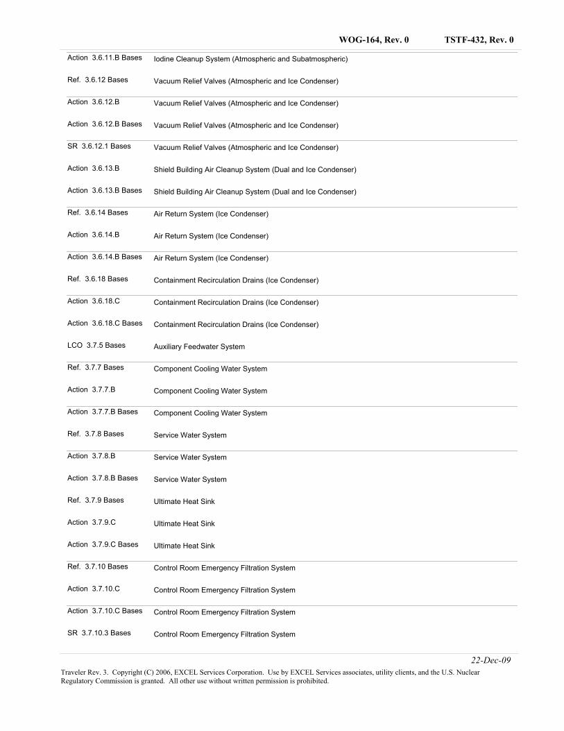
TSTF-432, Rev. 0WOG-164, Rev. 0
Action 3.6.11.B Bases Iodine Cleanup System (Atmospheric and Subatmospheric)
Ref. 3.6.12 Bases Vacuum Relief Valves (Atmospheric and Ice Condenser)
Action 3.6.12.B Vacuum Relief Valves (Atmospheric and Ice Condenser)
Action 3.6.12.B Bases Vacuum Relief Valves (Atmospheric and Ice Condenser)
SR 3.6.12.1 Bases Vacuum Relief Valves (Atmospheric and Ice Condenser)
Action 3.6.13.B Shield Building Air Cleanup System (Dual and Ice Condenser)
Action 3.6.13.B Bases Shield Building Air Cleanup System (Dual and Ice Condenser)
Ref. 3.6.14 Bases Air Return System (Ice Condenser)
Action 3.6.14.B Air Return System (Ice Condenser)
Action 3.6.14.B Bases Air Return System (Ice Condenser)
Ref. 3.6.18 Bases Containment Recirculation Drains (Ice Condenser)
Action 3.6.18.C Containment Recirculation Drains (Ice Condenser)
Action 3.6.18.C Bases Containment Recirculation Drains (Ice Condenser)
LCO 3.7.5 Bases Auxiliary Feedwater System
Ref. 3.7.7 Bases Component Cooling Water System
Action 3.7.7.B Component Cooling Water System
Action 3.7.7.B Bases Component Cooling Water System
Ref. 3.7.8 Bases Service Water System
Action 3.7.8.B Service Water System
Action 3.7.8.B Bases Service Water System
Ref. 3.7.9 Bases Ultimate Heat Sink
Action 3.7.9.C Ultimate Heat Sink
Action 3.7.9.C Bases Ultimate Heat Sink
Ref. 3.7.10 Bases Control Room Emergency Filtration System
Action 3.7.10.C Control Room Emergency Filtration System
Action 3.7.10.C Bases Control Room Emergency Filtration System
SR 3.7.10.3 Bases Control Room Emergency Filtration System
22-Dec-09Traveler Rev. 3. Copyright (C) 2006, EXCEL Services Corporation. Use by EXCEL Services associates, utility clients, and the U.S. Nuclear Regulatory Commission is granted. All other use without written permission is prohibited.
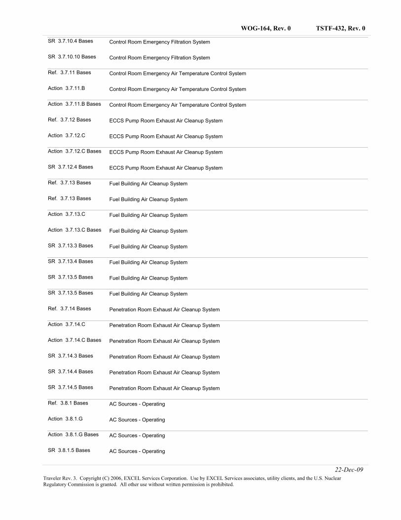
TSTF-432, Rev. 0WOG-164, Rev. 0
SR 3.7.10.4 Bases Control Room Emergency Filtration System
SR 3.7.10.10 Bases Control Room Emergency Filtration System
Ref. 3.7.11 Bases Control Room Emergency Air Temperature Control System
Action 3.7.11.B Control Room Emergency Air Temperature Control System
Action 3.7.11.B Bases Control Room Emergency Air Temperature Control System
Ref. 3.7.12 Bases ECCS Pump Room Exhaust Air Cleanup System
Action 3.7.12.C ECCS Pump Room Exhaust Air Cleanup System
Action 3.7.12.C Bases ECCS Pump Room Exhaust Air Cleanup System
SR 3.7.12.4 Bases ECCS Pump Room Exhaust Air Cleanup System
Ref. 3.7.13 Bases Fuel Building Air Cleanup System
Ref. 3.7.13 Bases Fuel Building Air Cleanup System
Action 3.7.13.C Fuel Building Air Cleanup System
Action 3.7.13.C Bases Fuel Building Air Cleanup System
SR 3.7.13.3 Bases Fuel Building Air Cleanup System
SR 3.7.13.4 Bases Fuel Building Air Cleanup System
SR 3.7.13.5 Bases Fuel Building Air Cleanup System
SR 3.7.13.5 Bases Fuel Building Air Cleanup System
Ref. 3.7.14 Bases Penetration Room Exhaust Air Cleanup System
Action 3.7.14.C Penetration Room Exhaust Air Cleanup System
Action 3.7.14.C Bases Penetration Room Exhaust Air Cleanup System
SR 3.7.14.3 Bases Penetration Room Exhaust Air Cleanup System
SR 3.7.14.4 Bases Penetration Room Exhaust Air Cleanup System
SR 3.7.14.5 Bases Penetration Room Exhaust Air Cleanup System
Ref. 3.8.1 Bases AC Sources - Operating
Action 3.8.1.G AC Sources - Operating
Action 3.8.1.G Bases AC Sources - Operating
SR 3.8.1.5 Bases AC Sources - Operating
22-Dec-09Traveler Rev. 3. Copyright (C) 2006, EXCEL Services Corporation. Use by EXCEL Services associates, utility clients, and the U.S. Nuclear Regulatory Commission is granted. All other use without written permission is prohibited.
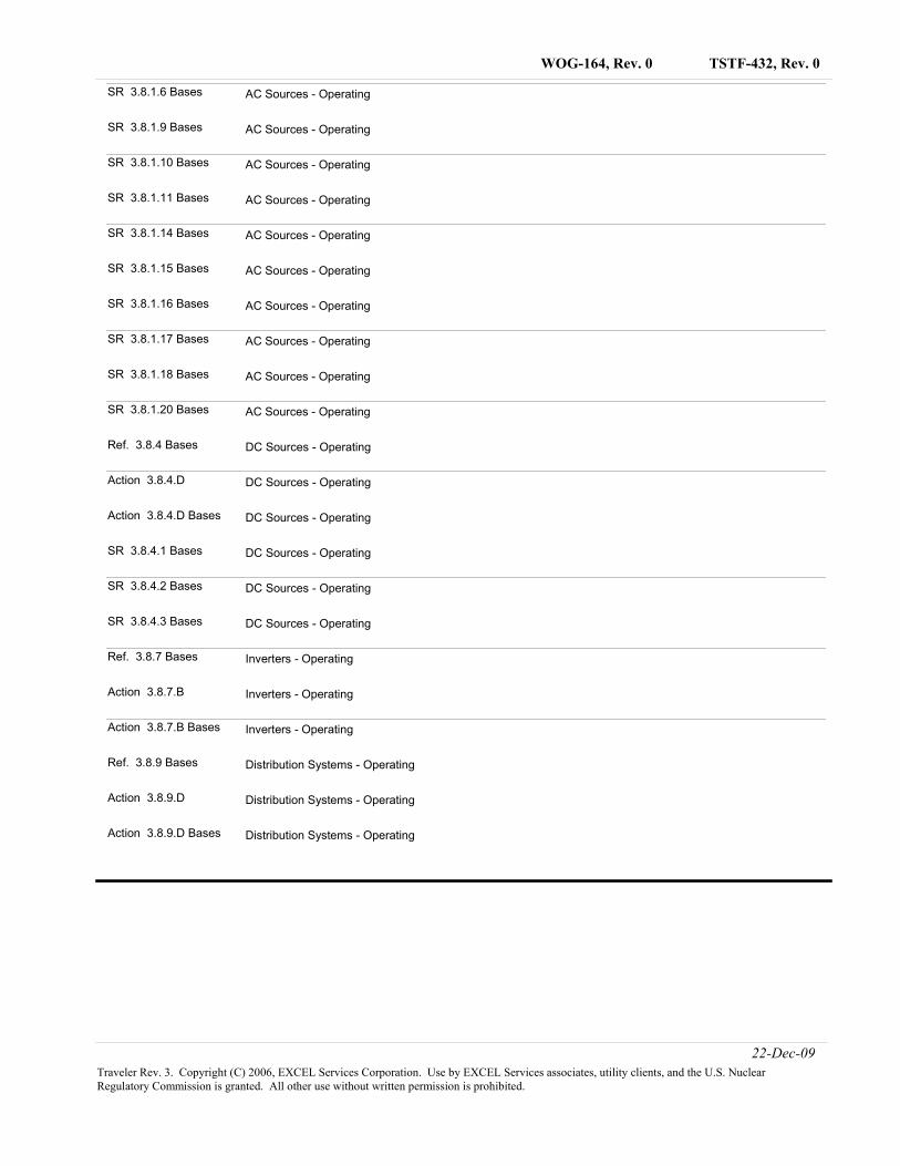
TSTF-432, Rev. 0WOG-164, Rev. 0
SR 3.8.1.6 Bases AC Sources - Operating
SR 3.8.1.9 Bases AC Sources - Operating
SR 3.8.1.10 Bases AC Sources - Operating
SR 3.8.1.11 Bases AC Sources - Operating
SR 3.8.1.14 Bases AC Sources - Operating
SR 3.8.1.15 Bases AC Sources - Operating
SR 3.8.1.16 Bases AC Sources - Operating
SR 3.8.1.17 Bases AC Sources - Operating
SR 3.8.1.18 Bases AC Sources - Operating
SR 3.8.1.20 Bases AC Sources - Operating
Ref. 3.8.4 Bases DC Sources - Operating
Action 3.8.4.D DC Sources - Operating
Action 3.8.4.D Bases DC Sources - Operating
SR 3.8.4.1 Bases DC Sources - Operating
SR 3.8.4.2 Bases DC Sources - Operating
SR 3.8.4.3 Bases DC Sources - Operating
Ref. 3.8.7 Bases Inverters - Operating
Action 3.8.7.B Inverters - Operating
Action 3.8.7.B Bases Inverters - Operating
Ref. 3.8.9 Bases Distribution Systems - Operating
Action 3.8.9.D Distribution Systems - Operating
Action 3.8.9.D Bases Distribution Systems - Operating
22-Dec-09Traveler Rev. 3. Copyright (C) 2006, EXCEL Services Corporation. Use by EXCEL Services associates, utility clients, and the U.S. Nuclear Regulatory Commission is granted. All other use without written permission is prohibited.
TSTF-432, Rev. 0
Page 1
1.0 Description
WCAP-16294-NP-A, Rev. 1, "Risk-Informed Evaluation of Changes to Tech Spec Required Action Endstates for Westinghouse NSSS PWRs," (Ref. 1) evaluated the endstates in which the Technical Specification Actions require the unit to be placed if the Required Actions and associated Completion Times are not met. The Technical Specifications contained in NUREG-1431, "Standard Technical Specifications Westinghouse Plants," Revision 3 (Ref. 2), were reviewed to determine the proposed changes to the Required Action endstates. The endstates currently required by the Technical Specifications are defined based on transitioning the unit to a Mode or other specified condition in the Applicability in which the Technical Specification Limiting Condition for Operation (LCO) is not applicable. Mode 5 is the current endstate for LCOs that are applicable in Modes 1 through 4. The risk of the transition from Mode 1 to Mode 4 or Mode 5 depends on the equipment that is operable. For example, the transition from Mode 4 to Mode 5 can introduce additional risk since it is required to realign the unit from steam generator cooling to residual heat removal, or shutdown cooling. During this realignment, there is an increased potential for loss of shutdown cooling and loss of inventory events, which is reflected in the plant risk calculated using Probabilistic Risk Assessment (PRA). In addition, decay heat removal following a loss of offsite power event in Mode 5 is dependant on Emergency AC power, whereas, in Mode 4 the turbine-driven auxiliary feedwater pump is available without relying on Emergency AC power. Therefore, transitioning to Mode 5 may not always be the appropriate endstate from a risk perspective. WCAP-16294-NP-A, Rev. 1 evaluates and identifies the appropriate endstate for a number of Technical Specification Required Actions based on the risk of transitioning the unit from Mode 1 to the lower Modes. Mode 4 is justified as an acceptable alternate endstate to Mode 5. A risk-informed approach, consistent with Regulatory Guides 1.174 and 1.177 (References 3 and 4, respectively) was used to perform the endstate evaluation. The risk associated with the transition from Mode 1 to Modes 4 and 5, and then returning to Mode 1 operation, is assessed both qualitatively and quantitatively. In addition to assessing the risk impact, the impacts on defense-in-depth and safety margins are also considered. 2.0 Proposed Changes The Technical Specification Required Action endstates evaluated for the endstate change are contained in NUREG-1431, "Standard Technical Specifications Westinghouse Plants" (Ref. 2). The Technical Specification number, title, Condition, and current endstate evaluated and the proposed endstate are provided in the following Table:
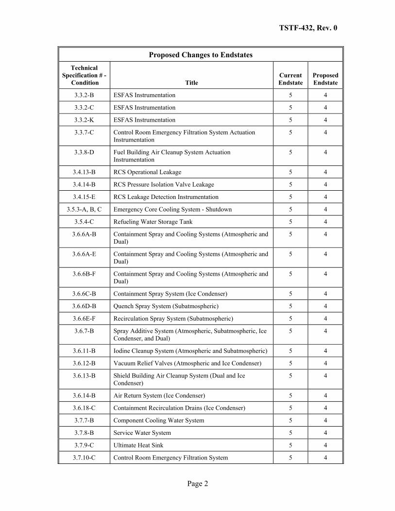
TSTF-432, Rev. 0
Page 2
Proposed Changes to Endstates
Technical Specification # -
Condition Title Current Endstate
ProposedEndstate
3.3.2-B ESFAS Instrumentation 5 4
3.3.2-C ESFAS Instrumentation 5 4
3.3.2-K ESFAS Instrumentation 5 4
3.3.7-C Control Room Emergency Filtration System Actuation Instrumentation
5 4
3.3.8-D Fuel Building Air Cleanup System Actuation Instrumentation
5 4
3.4.13-B RCS Operational Leakage 5 4
3.4.14-B RCS Pressure Isolation Valve Leakage 5 4
3.4.15-E RCS Leakage Detection Instrumentation 5 4
3.5.3-A, B, C Emergency Core Cooling System - Shutdown 5 4
3.5.4-C Refueling Water Storage Tank 5 4
3.6.6A-B Containment Spray and Cooling Systems (Atmospheric and Dual)
5 4
3.6.6A-E Containment Spray and Cooling Systems (Atmospheric and Dual)
5 4
3.6.6B-F Containment Spray and Cooling Systems (Atmospheric and Dual)
5 4
3.6.6C-B Containment Spray System (Ice Condenser) 5 4
3.6.6D-B Quench Spray System (Subatmospheric) 5 4
3.6.6E-F Recirculation Spray System (Subatmospheric) 5 4
3.6.7-B Spray Additive System (Atmospheric, Subatmospheric, Ice Condenser, and Dual)
5 4
3.6.11-B Iodine Cleanup System (Atmospheric and Subatmospheric) 5 4
3.6.12-B Vacuum Relief Valves (Atmospheric and Ice Condenser) 5 4
3.6.13-B Shield Building Air Cleanup System (Dual and Ice Condenser)
5 4
3.6.14-B Air Return System (Ice Condenser) 5 4
3.6.18-C Containment Recirculation Drains (Ice Condenser) 5 4
3.7.7-B Component Cooling Water System 5 4
3.7.8-B Service Water System 5 4
3.7.9-C Ultimate Heat Sink 5 4
3.7.10-C Control Room Emergency Filtration System 5 4
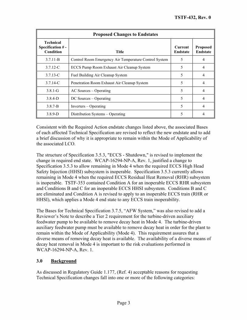
TSTF-432, Rev. 0
Page 3
Proposed Changes to Endstates
Technical Specification # -
Condition Title Current Endstate
ProposedEndstate
3.7.11-B Control Room Emergency Air Temperature Control System 5 4
3.7.12-C ECCS Pump Room Exhaust Air Cleanup System 5 4
3.7.13-C Fuel Building Air Cleanup System 5 4
3.7.14-C Penetration Room Exhaust Air Cleanup System 5 4
3.8.1-G AC Sources – Operating 5 4
3.8.4-D DC Sources – Operating 5 4
3.8.7-B Inverters – Operating 5 4
3.8.9-D Distribution Systems – Operating 5 4
Consistent with the Required Action endstate changes listed above, the associated Bases of each affected Technical Specification are revised to reflect the new endstate and to add a brief discussion of why it is appropriate to remain within the Mode of Applicability of the associated LCO. The structure of Specification 3.5.3, "ECCS - Shutdown," is revised to implement the change in required end state. WCAP-16294-NP-A, Rev. 1, justified a change to Specification 3.5.3 to allow remaining in Mode 4 when the required ECCS High Head Safety Injection (HHSI) subsystem is inoperable. Specification 3.5.3 currently allows remaining in Mode 4 when the required ECCS Residual Heat Removal (RHR) subsystem is inoperable. TSTF-353 contained Condition A for an inoperable ECCS RHR subsystem and Conditions B and C for an inoperable ECCS HHSI subsystem. Conditions B and C are eliminated and Condition A is revised to apply to an inoperable ECCS train (RHR or HHSI), which applies a Mode 4 end state to any ECCS train inoperability. The Bases for Technical Specification 3.7.5, “AFW System,” was also revised to add a Reviewer’s Note to describe a Tier 2 requirement for the turbine-driven auxiliary feedwater pump to be available to remove decay heat in Mode 4. The turbine-driven auxiliary feedwater pump must be available to remove decay heat in order for the plant to remain within the Mode of Applicability (Mode 4). This requirement assures that a diverse means of removing decay heat is available. The availability of a diverse means of decay heat removal in Mode 4 is important to the risk evaluations performed in WCAP-16294-NP-A, Rev. 1. 3.0 Background As discussed in Regulatory Guide 1.177, (Ref. 4) acceptable reasons for requesting Technical Specification changes fall into one or more of the following categories:
TSTF-432, Rev. 0
Page 4
• Improvement to Operational Safety: A change to the Technical Specifications can be made due to reductions in the plant risk or a reduction in the occupational exposure of plant personnel in complying with the Technical Specification requirements.
• Consistency with Risk Basis in Regulatory Requirements: Technical Specification requirements can be changed to reflect improved design features in a plant or to reflect equipment reliability improvements that make a previous requirement unnecessarily stringent or ineffective. Technical Specifications may be changed to establish consistently based requirements across the industry or across an industry group.
• Reduce Unnecessary Burdens: The change may be requested to reduce unnecessary burdens in complying with current Technical Specification requirements, based on operating history of the plant or industry in general. This includes extending completion times 1) that are too short to complete repairs when components fail with the plant at-power, 2) to complete additional maintenance activities at-power to reduce plant down time, and 3) to provide increased flexibility to plant operators.
The benefits of revising the Technical Specification Required Action endstates are related primarily to the first two categories. With regard to operational safety, the risk of the transition from Mode 1 to Mode 4 is lower than the risk of the transition from Mode 1 to Mode 5. The additional mode transition (Mode 4 to Mode 5) involves re-aligning the unit from steam generator cooling to residual heat removal or shutdown cooling . This activity requires system alignment changes that can lead to loss of inventory events and loss of shutdown cooling in the PRA. In addition, in Mode 4, as opposed to Mode 5, additional systems are available for event mitigation that provide a reduced risk once the unit has transitioned to the required endstate. For example, for a loss of offsite power/station blackout (LOSP/SBO) event in the PRA, the turbine driven auxiliary feedwater pump will be available for decay heat removal in Mode 4. In Mode 5, this capability is not available. Revising the Required Action endstate will also result in increasing unit availability by decreasing the time shutdown. The additional time required to transition to Mode 5 from Mode 4 when shutting down and also to Mode 4 from Mode 5 when restarting can be eliminated with the endstate change. A typical time for the transition from Mode 4 to Mode 5 during shutdown and from Mode 5 to 4 during startup is 24 hours. As such, this change will allow a time reduction of 24 hours. 4.0 Technical Analysis
The proposed endstate changes (described in Section 2.0 of this TSTF) are technically justified in WCAP-16294-A, Rev. 1 (Ref. 1).
TSTF-432, Rev. 0
Page 5
5.0 Regulatory Analysis
5.1 No Significant Hazards Consideration
The TSTF has evaluated whether or not a significant hazards consideration is involved with the proposed amendments by focusing on the three standards set forth in 10 CFR 50.92, "Issuance of amendment," as discussed below:
1. Does the proposed change involve a significant increase in the probability or consequences of an accident previously evaluated?
Response: No.
The proposed change modifies the end state (e.g., mode or other specified condition) which the Required Actions specify must be entered if compliance with the LCO is not restored. The requested technical specifications (TS) permit an end state of Mode 4 rather than an end state of Mode 5 contained in the current TS. In some cases, other Conditions and Required Actions are revised to implement the proposed change. Required Actions are not an initiator of any accident previously evaluated. Therefore, the proposed change does not affect the probability of any accident previously evaluated. The affected systems continued to be required to be operable by the Technical Specifications and the Completion Times specified in the Technical Specifications to restore equipment to operable status or take other remedial Actions remain unchanged. WCAP-16294-NP-A, Rev. 1, "Risk-Informed Evaluation of Changes to Tech Spec Required Action Endstates for Westinghouse NSSS PWRs," demonstrates that the proposed change does not significantly increase the consequences of any accident previously evaluated.
Therefore, the proposed change does not involve a significant increase in the probability or consequences of an accident previously evaluated.
2. Does the proposed change create the possibility of a new or different kind of accident from any accident previously evaluated?
Response: No.
The proposed change modifies the end state (e.g., mode or other specified condition) which the Required Actions specify must be entered if compliance with the LCO is not restored. In some cases, other Conditions and Required Actions are revised to implement the proposed change. The change does not involve a physical alteration of the plant (i.e., no new or different type of equipment will be installed) or a change in the methods governing normal plant operation. In addition, the change does not impose any new requirements. The change does not alter assumptions made in the safety analysis.
Therefore, the proposed change does not create the possibility of a new or different kind of accident from any accident previously evaluated.
TSTF-432, Rev. 0
Page 6
3. Does the proposed change involve a significant reduction in a margin of safety?
Response: No.
The proposed change modifies the end state (e.g., mode or other specified condition) which the Required Actions specify must be entered if compliance with the LCO is not restored. In some cases, other Conditions and Required Actions are revised to implement the proposed change. Remaining within the Applicability of the LCO is acceptable because WCAP-16294-NP-A demonstrates that the plant risk in MODE 4 is similar to or lower than MODE 5. As a result, no margin of safety is significantly affected. Therefore, the proposed changes do not involve a significant reduction in a margin of safety.
Based on the above, the TSTF concludes that the proposed changes present no significant hazards consideration under the standards set forth in 10 CFR 50.92(c), and, accordingly, a finding of "no significant hazards consideration" is justified.
5.2 Applicable Regulatory Requirements/Criteria
The proposed changes do not affect the design requirements or operability requirements of any plant system. The proposed changes involve changes to Technical Specification Required Actions for inoperable components or systems. 10 CFR 50.36 is the only applicable regulatory requirement. 10 CFR 50.36 contains requirements applicable to the content of plant Technical Specifications (e.g., the criteria for selecting systems, structures, or components that should be included in the Technical Specifications, and that appropriate surveillances be included, etc.) however 10 CFR 50.36 does not specify the Required Actions to be included for each Technical Specification. As such, the Technical Specifications affected by the proposed changes continue to meet the requirements contained in 10 CFR 50.36. Therefore, the Technical Specifications affected by the proposed changes remain consistent with the requirements of 10 CFR 50.36. Regulatory Guide (RG) 1.174, Rev. 1 and RG 1.177 (References 3 and 4) provide guidance for making Technical Specification changes using risk insights. The proposed risk-informed changes are consistent with the guidance provided in these Regulatory Guides . In summary, the proposed changes do not involve any design changes or changes to the physical arrangement of components. The proposed changes only revise the current Technical Specification Required Actions and therefore continue to satisfy the requirements of 10 CFR 50.36 and the guidance contained in RG 1.174, Rev. 1 and RG 1.177 for changes to the Technical Specification. Therefore, the proposed changes do not adversely impact the design or performance characteristics of any components or systems.
TSTF-432, Rev. 0
Page 7
In conclusion, based on the considerations discussed above, (1) there is reasonable assurance that the health and safety of the public will not be endangered by operation in the proposed manner, (2) such activities will be conducted in compliance with the Commission’s regulations, and (3) the approval of the proposed changes will not be inimical to the common defense and security or to the health and safety of the public. 6.0 Environmental Considerations A review has determined that the proposed changes would change a requirement with respect to installation or use of a facility component located within the restricted area, as defined in 10 CFR 20, or would change an inspection or surveillance requirement. However, the proposed changes do not involve (i) a significant hazards consideration, (ii) a significant change in the types or significant increase in the amounts of any effluent that may be released offsite, or (iii) a significant increase in individual or cumulative occupational radiation exposure. Accordingly, the proposed changes meet the eligibility criterion for categorical exclusion set forth in 10 CFR 51.22(c)(9). Therefore, pursuant to 10 CFR 51.22(b), no environmental impact statement or environmental assessment need be prepared in connection with the proposed changes. 7.0 References
1. WCAP-16294-NP-A, Rev. 1, "Risk-Informed Evaluation of Changes to Technical Specification Required Action Endstates for Westinghouse NSSS PWRs," [Date to be provided later.]
2. NUREG-1431, "Standard Technical Specifications Westinghouse Plants," Rev. 3, March 2004.
3. Regulatory Guide 1.174, Rev. 1 "An Approach for Using Probabilistic Risk Assessment in Risk-Informed Decisions on Plant-Specific Changes to the Licensing Basis," November 2002.
4. Regulatory Guide 1.177, "An Approach for Plant-Specific, Risk-Informed Decisionmaking: Technical Specifications," August 1998.
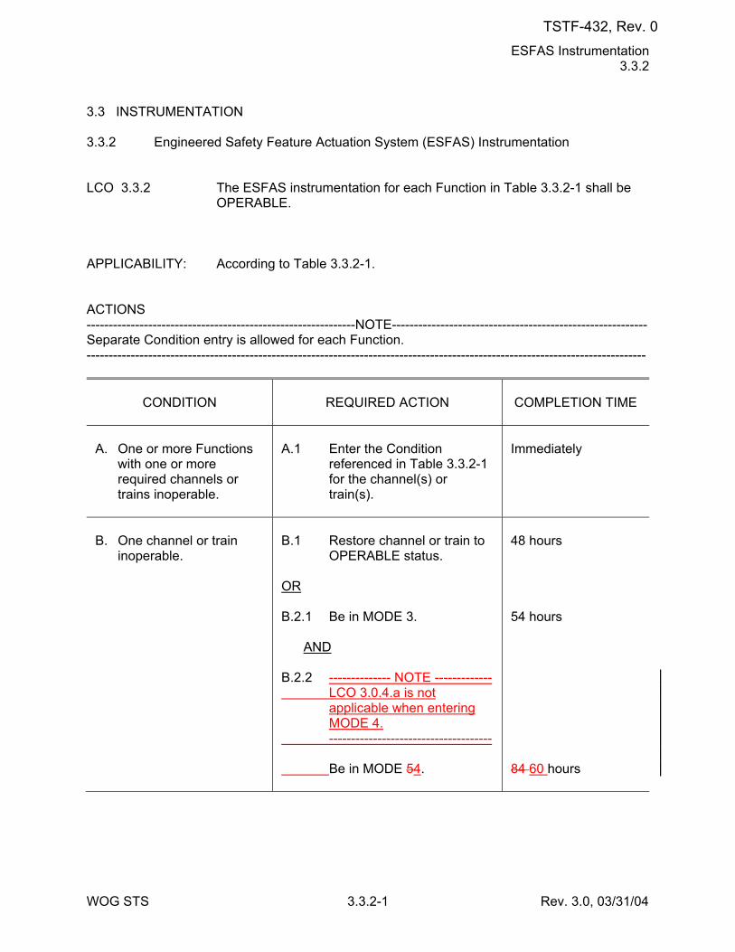
ESFAS Instrumentation 3.3.2
WOG STS 3.3.2-1 Rev. 3.0, 03/31/04
3.3 INSTRUMENTATION 3.3.2 Engineered Safety Feature Actuation System (ESFAS) Instrumentation LCO 3.3.2 The ESFAS instrumentation for each Function in Table 3.3.2-1 shall be
OPERABLE. APPLICABILITY: According to Table 3.3.2-1. ACTIONS -------------------------------------------------------------NOTE---------------------------------------------------------- Separate Condition entry is allowed for each Function. -------------------------------------------------------------------------------------------------------------------------------
CONDITION
REQUIRED ACTION
COMPLETION TIME
A. One or more Functions
with one or more required channels or trains inoperable.
A.1 Enter the Condition
referenced in Table 3.3.2-1 for the channel(s) or train(s).
Immediately
B. One channel or train
inoperable.
B.1 Restore channel or train to
OPERABLE status. OR B.2.1 Be in MODE 3. AND B.2.2 -------------- NOTE ------------- LCO 3.0.4.a is not
applicable when entering MODE 4.
------------------------------------- Be in MODE 54.
48 hours 54 hours 84 60 hours
TSTF-432, Rev. 0
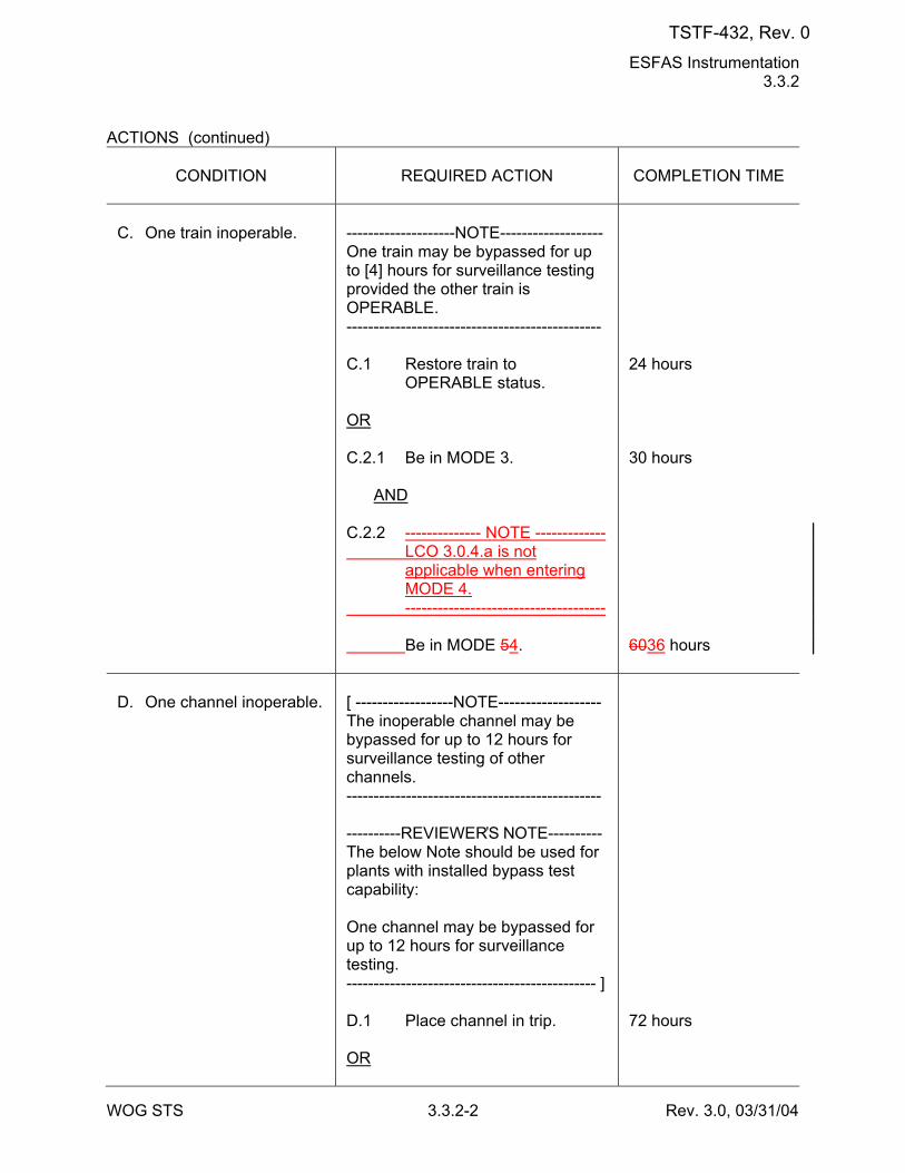
ESFAS Instrumentation 3.3.2
WOG STS 3.3.2-2 Rev. 3.0, 03/31/04
ACTIONS (continued)
CONDITION
REQUIRED ACTION
COMPLETION TIME
C. One train inoperable.
--------------------NOTE------------------- One train may be bypassed for up to [4] hours for surveillance testing provided the other train is OPERABLE. ----------------------------------------------- C.1 Restore train to
OPERABLE status. OR C.2.1 Be in MODE 3. AND C.2.2 -------------- NOTE ------------- LCO 3.0.4.a is not
applicable when entering MODE 4.
------------------------------------- Be in MODE 54.
24 hours 30 hours 6036 hours
D. One channel inoperable.
[ ------------------NOTE------------------- The inoperable channel may be bypassed for up to 12 hours for surveillance testing of other channels. ----------------------------------------------- ----------REVIEWER’S NOTE---------- The below Note should be used for plants with installed bypass test capability: One channel may be bypassed for up to 12 hours for surveillance testing. ---------------------------------------------- ] D.1 Place channel in trip. OR
72 hours
TSTF-432, Rev. 0
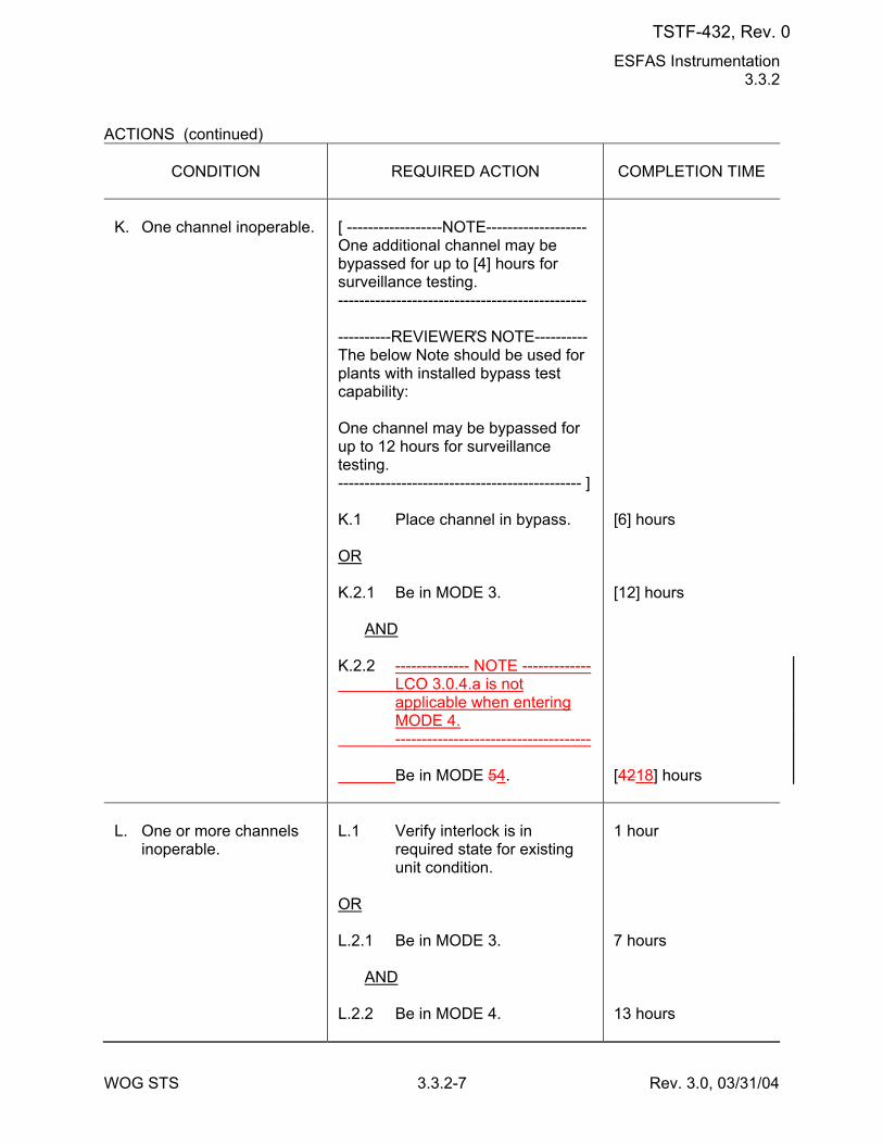
ESFAS Instrumentation 3.3.2
WOG STS 3.3.2-7 Rev. 3.0, 03/31/04
ACTIONS (continued)
CONDITION
REQUIRED ACTION
COMPLETION TIME
K. One channel inoperable.
[ ------------------NOTE------------------- One additional channel may be bypassed for up to [4] hours for surveillance testing. ----------------------------------------------- ----------REVIEWER’S NOTE---------- The below Note should be used for plants with installed bypass test capability: One channel may be bypassed for up to 12 hours for surveillance testing. ---------------------------------------------- ] K.1 Place channel in bypass. OR K.2.1 Be in MODE 3. AND K.2.2 -------------- NOTE ------------- LCO 3.0.4.a is not
applicable when entering MODE 4.
------------------------------------- Be in MODE 54.
[6] hours [12] hours [4218] hours
L. One or more channels
inoperable.
L.1 Verify interlock is in
required state for existing unit condition.
OR L.2.1 Be in MODE 3. AND L.2.2 Be in MODE 4.
1 hour 7 hours 13 hours
TSTF-432, Rev. 0
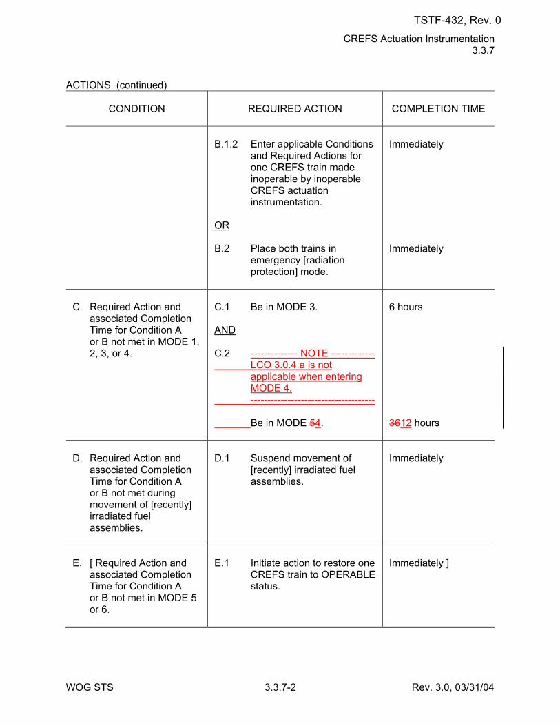
CREFS Actuation Instrumentation 3.3.7
WOG STS 3.3.7-2 Rev. 3.0, 03/31/04
ACTIONS (continued)
CONDITION
REQUIRED ACTION
COMPLETION TIME
B.1.2 Enter applicable Conditions
and Required Actions for one CREFS train made inoperable by inoperable CREFS actuation instrumentation.
OR B.2 Place both trains in
emergency [radiation protection] mode.
Immediately Immediately
C. Required Action and
associated Completion Time for Condition A or B not met in MODE 1, 2, 3, or 4.
C.1 Be in MODE 3. AND C.2 -------------- NOTE ------------- LCO 3.0.4.a is not
applicable when entering MODE 4.
------------------------------------- Be in MODE 54.
6 hours 3612 hours
D. Required Action and
associated Completion Time for Condition A or B not met during movement of [recently] irradiated fuel assemblies.
D.1 Suspend movement of
[recently] irradiated fuel assemblies.
Immediately
E. [ Required Action and
associated Completion Time for Condition A or B not met in MODE 5 or 6.
E.1 Initiate action to restore one
CREFS train to OPERABLE status.
Immediately ]
TSTF-432, Rev. 0
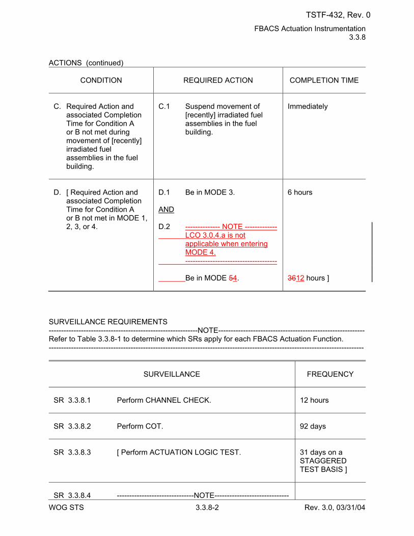
FBACS Actuation Instrumentation 3.3.8
WOG STS 3.3.8-2 Rev. 3.0, 03/31/04
ACTIONS (continued)
CONDITION
REQUIRED ACTION
COMPLETION TIME
C. Required Action and
associated Completion Time for Condition A or B not met during movement of [recently] irradiated fuel assemblies in the fuel building.
C.1 Suspend movement of
[recently] irradiated fuel assemblies in the fuel building.
Immediately
D. [ Required Action and
associated Completion Time for Condition A or B not met in MODE 1, 2, 3, or 4.
D.1 Be in MODE 3. AND D.2 -------------- NOTE ------------- LCO 3.0.4.a is not
applicable when entering MODE 4.
------------------------------------- Be in MODE 54.
6 hours 3612 hours ]
SURVEILLANCE REQUIREMENTS ------------------------------------------------------------NOTE----------------------------------------------------------- Refer to Table 3.3.8-1 to determine which SRs apply for each FBACS Actuation Function. -------------------------------------------------------------------------------------------------------------------------------
SURVEILLANCE
FREQUENCY
SR 3.3.8.1 Perform CHANNEL CHECK.
12 hours
SR 3.3.8.2 Perform COT.
92 days
SR 3.3.8.3 [ Perform ACTUATION LOGIC TEST.
31 days on a STAGGERED TEST BASIS ]
SR 3.3.8.4 -------------------------------NOTE------------------------------
TSTF-432, Rev. 0
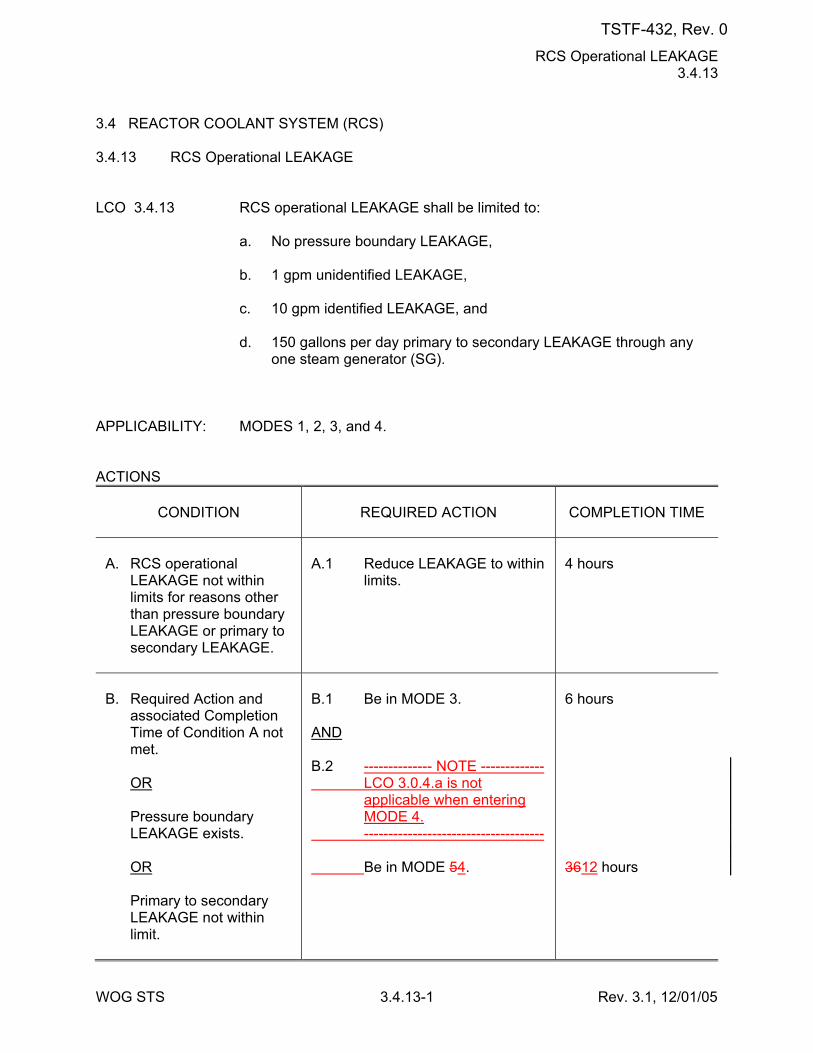
RCS Operational LEAKAGE 3.4.13
WOG STS 3.4.13-1 Rev. 3.1, 12/01/05
3.4 REACTOR COOLANT SYSTEM (RCS) 3.4.13 RCS Operational LEAKAGE LCO 3.4.13 RCS operational LEAKAGE shall be limited to: a. No pressure boundary LEAKAGE, b. 1 gpm unidentified LEAKAGE, c. 10 gpm identified LEAKAGE, and d. 150 gallons per day primary to secondary LEAKAGE through any
one steam generator (SG). APPLICABILITY: MODES 1, 2, 3, and 4. ACTIONS
CONDITION
REQUIRED ACTION
COMPLETION TIME
A. RCS operational
LEAKAGE not within limits for reasons other than pressure boundary LEAKAGE or primary to secondary LEAKAGE.
A.1 Reduce LEAKAGE to within
limits.
4 hours
B. Required Action and
associated Completion Time of Condition A not met.
OR Pressure boundary
LEAKAGE exists. OR Primary to secondary
LEAKAGE not within limit.
B.1 Be in MODE 3. AND B.2 -------------- NOTE ------------- LCO 3.0.4.a is not
applicable when entering MODE 4.
------------------------------------- Be in MODE 54.
6 hours 3612 hours
TSTF-432, Rev. 0
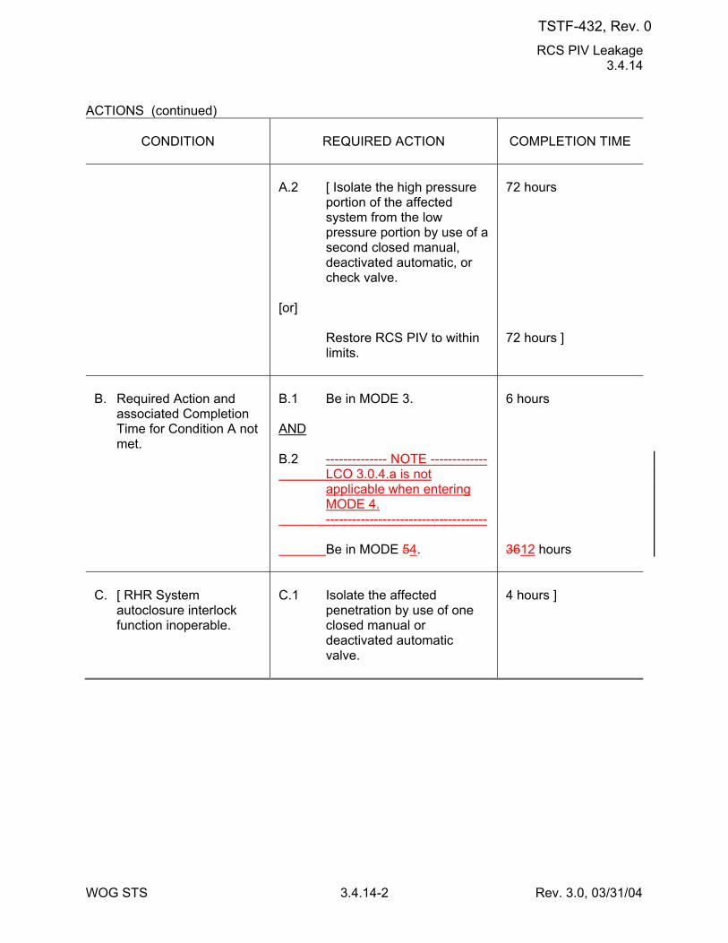
RCS PIV Leakage 3.4.14
WOG STS 3.4.14-2 Rev. 3.0, 03/31/04
ACTIONS (continued)
CONDITION
REQUIRED ACTION
COMPLETION TIME
A.2 [ Isolate the high pressure
portion of the affected system from the low pressure portion by use of a second closed manual, deactivated automatic, or check valve.
[or] Restore RCS PIV to within
limits.
72 hours 72 hours ]
B. Required Action and
associated Completion Time for Condition A not met.
B.1 Be in MODE 3. AND B.2 -------------- NOTE ------------- LCO 3.0.4.a is not
applicable when entering MODE 4.
------------------------------------- Be in MODE 54.
6 hours 3612 hours
C. [ RHR System
autoclosure interlock function inoperable.
C.1 Isolate the affected
penetration by use of one closed manual or deactivated automatic valve.
4 hours ]
TSTF-432, Rev. 0
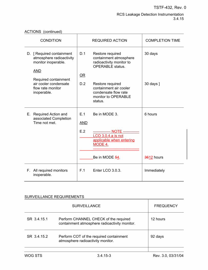
RCS Leakage Detection Instrumentation 3.4.15
WOG STS 3.4.15-3 Rev. 3.0, 03/31/04
ACTIONS (continued)
CONDITION
REQUIRED ACTION
COMPLETION TIME
D. [ Required containment
atmosphere radioactivity monitor inoperable.
AND Required containment
air cooler condensate flow rate monitor inoperable.
D.1 Restore required
containment atmosphere radioactivity monitor to OPERABLE status.
OR D.2 Restore required
containment air cooler condensate flow rate monitor to OPERABLE status.
30 days 30 days ]
E. Required Action and
associated Completion Time not met.
E.1 Be in MODE 3. AND E.2 -------------- NOTE ------------- LCO 3.0.4.a is not
applicable when entering MODE 4.
------------------------------------- Be in MODE 54.
6 hours 3612 hours
F. All required monitors
inoperable.
F.1 Enter LCO 3.0.3.
Immediately
SURVEILLANCE REQUIREMENTS
SURVEILLANCE
FREQUENCY
SR 3.4.15.1 Perform CHANNEL CHECK of the required
containment atmosphere radioactivity monitor.
12 hours
SR 3.4.15.2 Perform COT of the required containment
atmosphere radioactivity monitor.
92 days
TSTF-432, Rev. 0
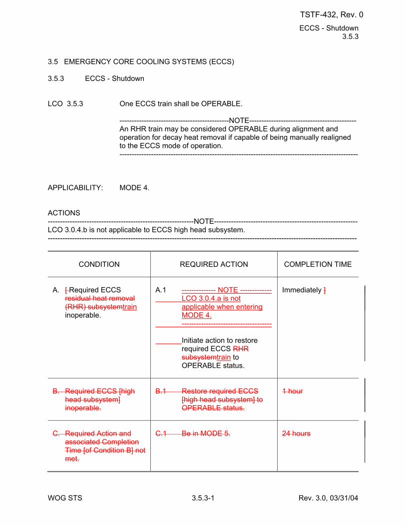
ECCS - Shutdown 3.5.3
WOG STS 3.5.3-1 Rev. 3.0, 03/31/04
3.5 EMERGENCY CORE COOLING SYSTEMS (ECCS) 3.5.3 ECCS - Shutdown LCO 3.5.3 One ECCS train shall be OPERABLE. ---------------------------------------------NOTE-------------------------------------------- An RHR train may be considered OPERABLE during alignment and
operation for decay heat removal if capable of being manually realigned to the ECCS mode of operation.
-------------------------------------------------------------------------------------------------- APPLICABILITY: MODE 4. ACTIONS ------------------------------------------------------------NOTE----------------------------------------------------------- LCO 3.0.4.b is not applicable to ECCS high head subsystem. -------------------------------------------------------------------------------------------------------------------------------
CONDITION
REQUIRED ACTION
COMPLETION TIME
A. [ Required ECCS
residual heat removal (RHR) subsystemtrain inoperable.
A.1 -------------- NOTE ------------- LCO 3.0.4.a is not
applicable when entering MODE 4.
------------------------------------- Initiate action to restore
required ECCS RHR subsystemtrain to OPERABLE status.
Immediately ]
B. Required ECCS [high
head subsystem] inoperable.
B.1 Restore required ECCS
[high head subsystem] to OPERABLE status.
1 hour
C. Required Action and
associated Completion Time [of Condition B] not met.
C.1 Be in MODE 5.
24 hours
TSTF-432, Rev. 0
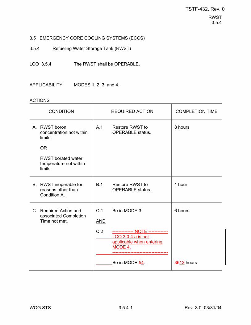
RWST 3.5.4
WOG STS 3.5.4-1 Rev. 3.0, 03/31/04
3.5 EMERGENCY CORE COOLING SYSTEMS (ECCS) 3.5.4 Refueling Water Storage Tank (RWST) LCO 3.5.4 The RWST shall be OPERABLE. APPLICABILITY: MODES 1, 2, 3, and 4. ACTIONS
CONDITION
REQUIRED ACTION
COMPLETION TIME
A. RWST boron
concentration not within limits.
OR RWST borated water
temperature not within limits.
A.1 Restore RWST to
OPERABLE status.
8 hours
B. RWST inoperable for
reasons other than Condition A.
B.1 Restore RWST to
OPERABLE status.
1 hour
C. Required Action and
associated Completion Time not met.
C.1 Be in MODE 3. AND C.2 -------------- NOTE ------------- LCO 3.0.4.a is not
applicable when entering MODE 4.
------------------------------------- Be in MODE 54.
6 hours 3612 hours
TSTF-432, Rev. 0
Containment Spray and Cooling Systems (Atmospheric and Dual) 3.6.6A
WOG STS 3.6.6A-1 Rev. 3.1, 12/01/05
3.6 CONTAINMENT SYSTEMS 3.6.6A Containment Spray and Cooling Systems (Atmospheric and Dual) (Credit taken for
iodine removal by the Containment Spray System) LCO 3.6.6A Two containment spray trains and [two] containment cooling trains shall
be OPERABLE. APPLICABILITY: MODES 1, 2, 3, and 4. ACTIONS
CONDITION
REQUIRED ACTION
COMPLETION TIME
A. One containment spray
train inoperable.
A.1 Restore containment spray
train to OPERABLE status.
72 hours
B. Required Action and
associated Completion Time of Condition A not met.
B.1 Be in MODE 3. AND B.2 -------------- NOTE ------------- LCO 3.0.4.a is not
applicable when entering MODE 4.
------------------------------------- Be in MODE 54.
6 hours 8454 hours
C. One [required]
containment cooling train inoperable.
C.1 Restore [required]
containment cooling train to OPERABLE status.
7 days
D. Two [required]
containment cooling trains inoperable.
D.1 Restore one [required]
containment cooling train to OPERABLE status.
72 hours
E. Required Action and
associated Completion Time of Condition C or D not met.
E.1 Be in MODE 3. AND
6 hours
TSTF-432, Rev. 0
Containment Spray and Cooling Systems (Atmospheric and Dual) 3.6.6A
WOG STS 3.6.6A-2 Rev. 3.1, 12/01/05
CONDITION
REQUIRED ACTION
COMPLETION TIME
E.2 -------------- NOTE ------------- LCO 3.0.4.a is not
applicable when entering MODE 4.
------------------------------------- Be in MODE 54.
3612 hours
TSTF-432, Rev. 0
Containment Spray and Cooling Systems (Atmospheric and Dual) 3.6.6B
WOG STS 3.6.6B-2 Rev. 3.1, 12/01/05
ACTIONS (continued)
CONDITION
REQUIRED ACTION
COMPLETION TIME
E. Two [required]
containment cooling trains inoperable.
E.1 Restore one [required]
containment cooling train to OPERABLE status.
72 hours
F. Required Action and
associated Completion Time of Condition A, B, C, D, or E not met.
F.1 Be in MODE 3. AND F.2 -------------- NOTE ------------- LCO 3.0.4.a is not
applicable when entering MODE 4.
------------------------------------- Be in MODE 54.
6 hours 3612 hours
G. Any combination of three
or more trains inoperable.
G.1 Enter LCO 3.0.3.
Immediately
SURVEILLANCE REQUIREMENTS
SURVEILLANCE
FREQUENCY
SR 3.6.6B.1 Verify each containment spray manual, power
operated, and automatic valve in the flow path that is not locked, sealed, or otherwise secured in position is in the correct position.
31 days
SR 3.6.6B.2 Operate each [required] containment cooling train
fan unit for ≥ 15 minutes.
31 days
SR 3.6.6B.3 Verify each [required] containment cooling train
cooling water flow rate is ≥ [700] gpm.
31 days
TSTF-432, Rev. 0
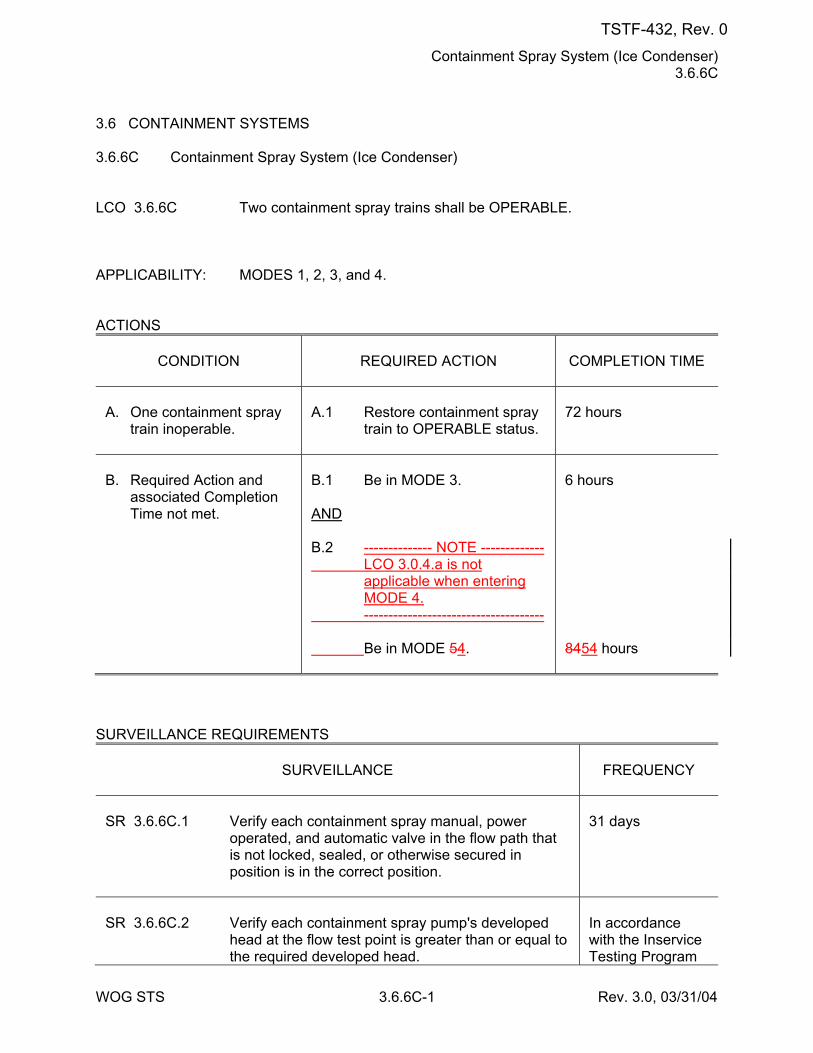
Containment Spray System (Ice Condenser) 3.6.6C
WOG STS 3.6.6C-1 Rev. 3.0, 03/31/04
3.6 CONTAINMENT SYSTEMS 3.6.6C Containment Spray System (Ice Condenser) LCO 3.6.6C Two containment spray trains shall be OPERABLE. APPLICABILITY: MODES 1, 2, 3, and 4. ACTIONS
CONDITION
REQUIRED ACTION
COMPLETION TIME
A. One containment spray
train inoperable.
A.1 Restore containment spray
train to OPERABLE status.
72 hours
B. Required Action and
associated Completion Time not met.
B.1 Be in MODE 3. AND B.2 -------------- NOTE ------------- LCO 3.0.4.a is not
applicable when entering MODE 4.
------------------------------------- Be in MODE 54.
6 hours 8454 hours
SURVEILLANCE REQUIREMENTS
SURVEILLANCE
FREQUENCY
SR 3.6.6C.1 Verify each containment spray manual, power
operated, and automatic valve in the flow path that is not locked, sealed, or otherwise secured in position is in the correct position.
31 days
SR 3.6.6C.2 Verify each containment spray pump's developed
head at the flow test point is greater than or equal to the required developed head.
In accordance with the Inservice Testing Program
TSTF-432, Rev. 0
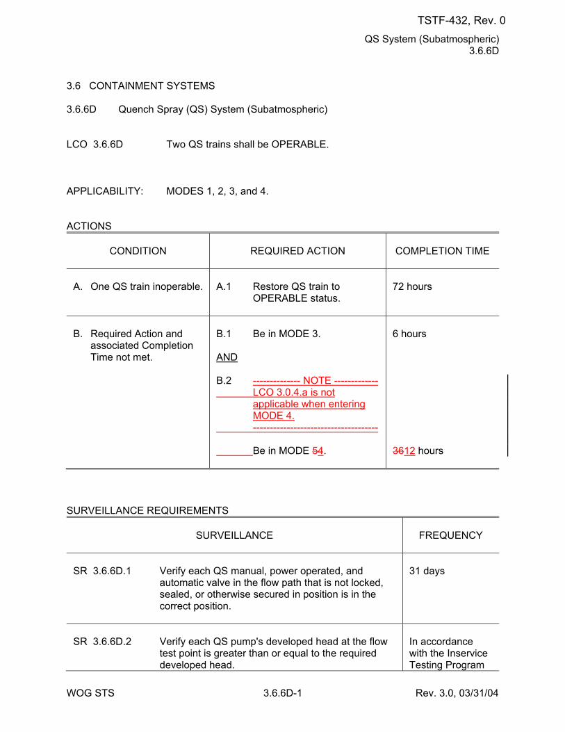
QS System (Subatmospheric) 3.6.6D
WOG STS 3.6.6D-1 Rev. 3.0, 03/31/04
3.6 CONTAINMENT SYSTEMS 3.6.6D Quench Spray (QS) System (Subatmospheric) LCO 3.6.6D Two QS trains shall be OPERABLE. APPLICABILITY: MODES 1, 2, 3, and 4. ACTIONS
CONDITION
REQUIRED ACTION
COMPLETION TIME
A. One QS train inoperable.
A.1 Restore QS train to
OPERABLE status.
72 hours
B. Required Action and
associated Completion Time not met.
B.1 Be in MODE 3. AND B.2 -------------- NOTE ------------- LCO 3.0.4.a is not
applicable when entering MODE 4.
------------------------------------- Be in MODE 54.
6 hours 3612 hours
SURVEILLANCE REQUIREMENTS
SURVEILLANCE
FREQUENCY
SR 3.6.6D.1 Verify each QS manual, power operated, and
automatic valve in the flow path that is not locked, sealed, or otherwise secured in position is in the correct position.
31 days
SR 3.6.6D.2 Verify each QS pump's developed head at the flow
test point is greater than or equal to the required developed head.
In accordance with the Inservice Testing Program
TSTF-432, Rev. 0
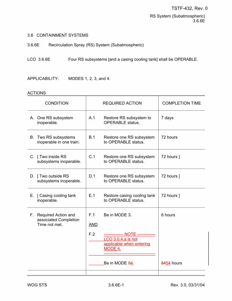
RS System (Subatmospheric) 3.6.6E
WOG STS 3.6.6E-1 Rev. 3.0, 03/31/04
3.6 CONTAINMENT SYSTEMS 3.6.6E Recirculation Spray (RS) System (Subatmospheric) LCO 3.6.6E Four RS subsystems [and a casing cooling tank] shall be OPERABLE. APPLICABILITY: MODES 1, 2, 3, and 4. ACTIONS
CONDITION
REQUIRED ACTION
COMPLETION TIME
A. One RS subsystem
inoperable.
A.1 Restore RS subsystem to
OPERABLE status.
7 days
B. Two RS subsystems
inoperable in one train.
B.1 Restore one RS subsystem
to OPERABLE status.
72 hours
C. [ Two inside RS
subsystems inoperable.
C.1 Restore one RS subsystem
to OPERABLE status.
72 hours ]
D. [ Two outside RS
subsystems inoperable.
D.1 Restore one RS subsystem
to OPERABLE status.
72 hours ]
E. [ Casing cooling tank
inoperable.
E.1 Restore casing cooling tank
to OPERABLE status.
72 hours ]
F. Required Action and
associated Completion Time not met.
F.1 Be in MODE 3. AND F.2 -------------- NOTE ------------- LCO 3.0.4.a is not
applicable when entering MODE 4.
------------------------------------- Be in MODE 54.
6 hours 8454 hours
TSTF-432, Rev. 0
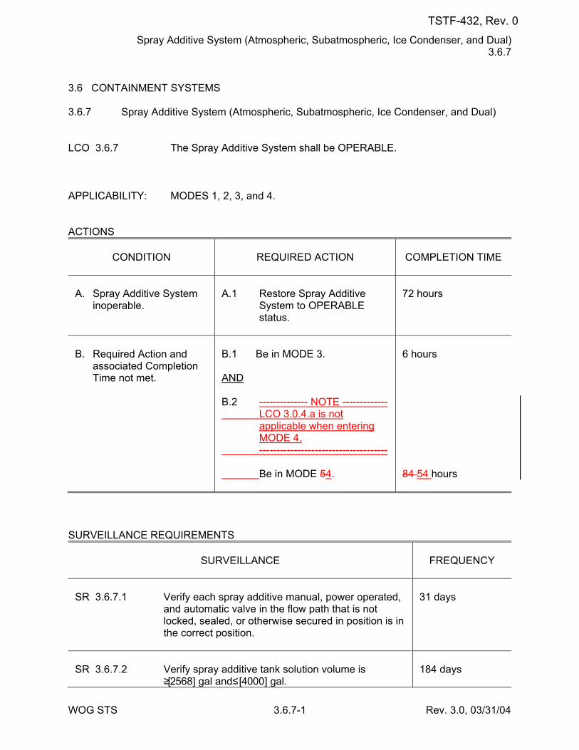
Spray Additive System (Atmospheric, Subatmospheric, Ice Condenser, and Dual) 3.6.7
WOG STS 3.6.7-1 Rev. 3.0, 03/31/04
3.6 CONTAINMENT SYSTEMS 3.6.7 Spray Additive System (Atmospheric, Subatmospheric, Ice Condenser, and Dual) LCO 3.6.7 The Spray Additive System shall be OPERABLE. APPLICABILITY: MODES 1, 2, 3, and 4. ACTIONS
CONDITION
REQUIRED ACTION
COMPLETION TIME
A. Spray Additive System
inoperable.
A.1 Restore Spray Additive
System to OPERABLE status.
72 hours
B. Required Action and
associated Completion Time not met.
B.1 Be in MODE 3. AND B.2 -------------- NOTE ------------- LCO 3.0.4.a is not
applicable when entering MODE 4.
------------------------------------- Be in MODE 54.
6 hours 84 54 hours
SURVEILLANCE REQUIREMENTS
SURVEILLANCE
FREQUENCY
SR 3.6.7.1 Verify each spray additive manual, power operated,
and automatic valve in the flow path that is not locked, sealed, or otherwise secured in position is in the correct position.
31 days
SR 3.6.7.2 Verify spray additive tank solution volume is
≥ [2568] gal and ≤ [4000] gal.
184 days
TSTF-432, Rev. 0
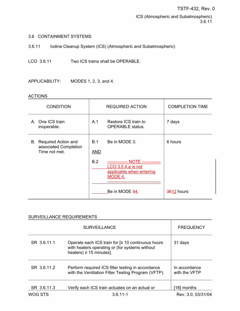
ICS (Atmospheric and Subatmospheric) 3.6.11
WOG STS 3.6.11-1 Rev. 3.0, 03/31/04
3.6 CONTAINMENT SYSTEMS 3.6.11 Iodine Cleanup System (ICS) (Atmospheric and Subatmospheric) LCO 3.6.11 Two ICS trains shall be OPERABLE. APPLICABILITY: MODES 1, 2, 3, and 4. ACTIONS
CONDITION
REQUIRED ACTION
COMPLETION TIME
A. One ICS train
inoperable.
A.1 Restore ICS train to
OPERABLE status.
7 days
B. Required Action and
associated Completion Time not met.
B.1 Be in MODE 3. AND B.2 -------------- NOTE ------------- LCO 3.0.4.a is not
applicable when entering MODE 4.
------------------------------------- Be in MODE 54.
6 hours 3612 hours
SURVEILLANCE REQUIREMENTS
SURVEILLANCE
FREQUENCY
SR 3.6.11.1 Operate each ICS train for [≥ 10 continuous hours
with heaters operating or (for systems without heaters) ≥ 15 minutes].
31 days
SR 3.6.11.2 Perform required ICS filter testing in accordance
with the Ventilation Filter Testing Program (VFTP).
In accordance with the VFTP
SR 3.6.11.3 Verify each ICS train actuates on an actual or
[18] months
TSTF-432, Rev. 0
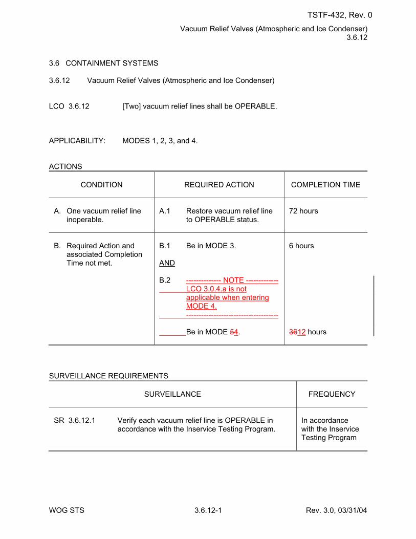
Vacuum Relief Valves (Atmospheric and Ice Condenser) 3.6.12
WOG STS 3.6.12-1 Rev. 3.0, 03/31/04
3.6 CONTAINMENT SYSTEMS 3.6.12 Vacuum Relief Valves (Atmospheric and Ice Condenser) LCO 3.6.12 [Two] vacuum relief lines shall be OPERABLE. APPLICABILITY: MODES 1, 2, 3, and 4. ACTIONS
CONDITION
REQUIRED ACTION
COMPLETION TIME
A. One vacuum relief line
inoperable.
A.1 Restore vacuum relief line
to OPERABLE status.
72 hours
B. Required Action and
associated Completion Time not met.
B.1 Be in MODE 3. AND B.2 -------------- NOTE ------------- LCO 3.0.4.a is not
applicable when entering MODE 4.
------------------------------------- Be in MODE 54.
6 hours 3612 hours
SURVEILLANCE REQUIREMENTS
SURVEILLANCE
FREQUENCY
SR 3.6.12.1 Verify each vacuum relief line is OPERABLE in
accordance with the Inservice Testing Program.
In accordance with the Inservice Testing Program
TSTF-432, Rev. 0
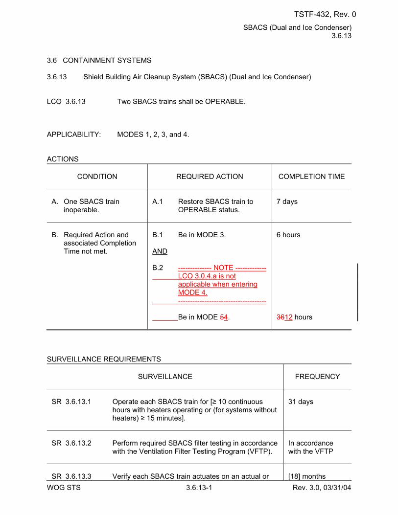
SBACS (Dual and Ice Condenser) 3.6.13
WOG STS 3.6.13-1 Rev. 3.0, 03/31/04
3.6 CONTAINMENT SYSTEMS 3.6.13 Shield Building Air Cleanup System (SBACS) (Dual and Ice Condenser) LCO 3.6.13 Two SBACS trains shall be OPERABLE. APPLICABILITY: MODES 1, 2, 3, and 4. ACTIONS
CONDITION
REQUIRED ACTION
COMPLETION TIME
A. One SBACS train
inoperable.
A.1 Restore SBACS train to
OPERABLE status.
7 days
B. Required Action and
associated Completion Time not met.
B.1 Be in MODE 3. AND B.2 -------------- NOTE ------------- LCO 3.0.4.a is not
applicable when entering MODE 4.
------------------------------------- Be in MODE 54.
6 hours 3612 hours
SURVEILLANCE REQUIREMENTS
SURVEILLANCE
FREQUENCY
SR 3.6.13.1 Operate each SBACS train for [≥ 10 continuous
hours with heaters operating or (for systems without heaters) ≥ 15 minutes].
31 days
SR 3.6.13.2 Perform required SBACS filter testing in accordance
with the Ventilation Filter Testing Program (VFTP).
In accordance with the VFTP
SR 3.6.13.3 Verify each SBACS train actuates on an actual or
[18] months
TSTF-432, Rev. 0
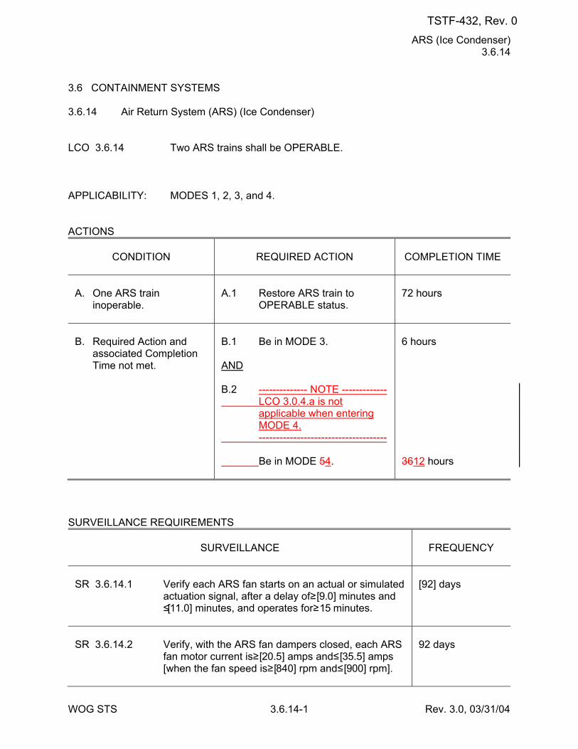
ARS (Ice Condenser) 3.6.14
WOG STS 3.6.14-1 Rev. 3.0, 03/31/04
3.6 CONTAINMENT SYSTEMS 3.6.14 Air Return System (ARS) (Ice Condenser) LCO 3.6.14 Two ARS trains shall be OPERABLE. APPLICABILITY: MODES 1, 2, 3, and 4. ACTIONS
CONDITION
REQUIRED ACTION
COMPLETION TIME
A. One ARS train
inoperable.
A.1 Restore ARS train to
OPERABLE status.
72 hours
B. Required Action and
associated Completion Time not met.
B.1 Be in MODE 3. AND B.2 -------------- NOTE ------------- LCO 3.0.4.a is not
applicable when entering MODE 4.
------------------------------------- Be in MODE 54.
6 hours 3612 hours
SURVEILLANCE REQUIREMENTS
SURVEILLANCE
FREQUENCY
SR 3.6.14.1 Verify each ARS fan starts on an actual or simulated
actuation signal, after a delay of ≥ [9.0] minutes and ≤ [11.0] minutes, and operates for ≥ 15 minutes.
[92] days
SR 3.6.14.2 Verify, with the ARS fan dampers closed, each ARS
fan motor current is ≥ [20.5] amps and ≤ [35.5] amps [when the fan speed is ≥ [840] rpm and ≤ [900] rpm].
92 days
TSTF-432, Rev. 0
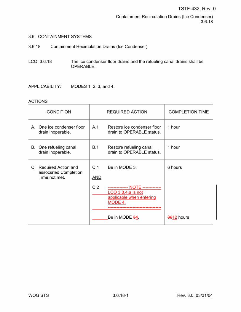
Containment Recirculation Drains (Ice Condenser) 3.6.18
WOG STS 3.6.18-1 Rev. 3.0, 03/31/04
3.6 CONTAINMENT SYSTEMS 3.6.18 Containment Recirculation Drains (Ice Condenser) LCO 3.6.18 The ice condenser floor drains and the refueling canal drains shall be
OPERABLE. APPLICABILITY: MODES 1, 2, 3, and 4. ACTIONS
CONDITION
REQUIRED ACTION
COMPLETION TIME
A. One ice condenser floor
drain inoperable.
A.1 Restore ice condenser floor
drain to OPERABLE status.
1 hour
B. One refueling canal
drain inoperable.
B.1 Restore refueling canal
drain to OPERABLE status.
1 hour
C. Required Action and
associated Completion Time not met.
C.1 Be in MODE 3. AND C.2 -------------- NOTE ------------- LCO 3.0.4.a is not
applicable when entering MODE 4.
------------------------------------- Be in MODE 54.
6 hours 3612 hours
TSTF-432, Rev. 0
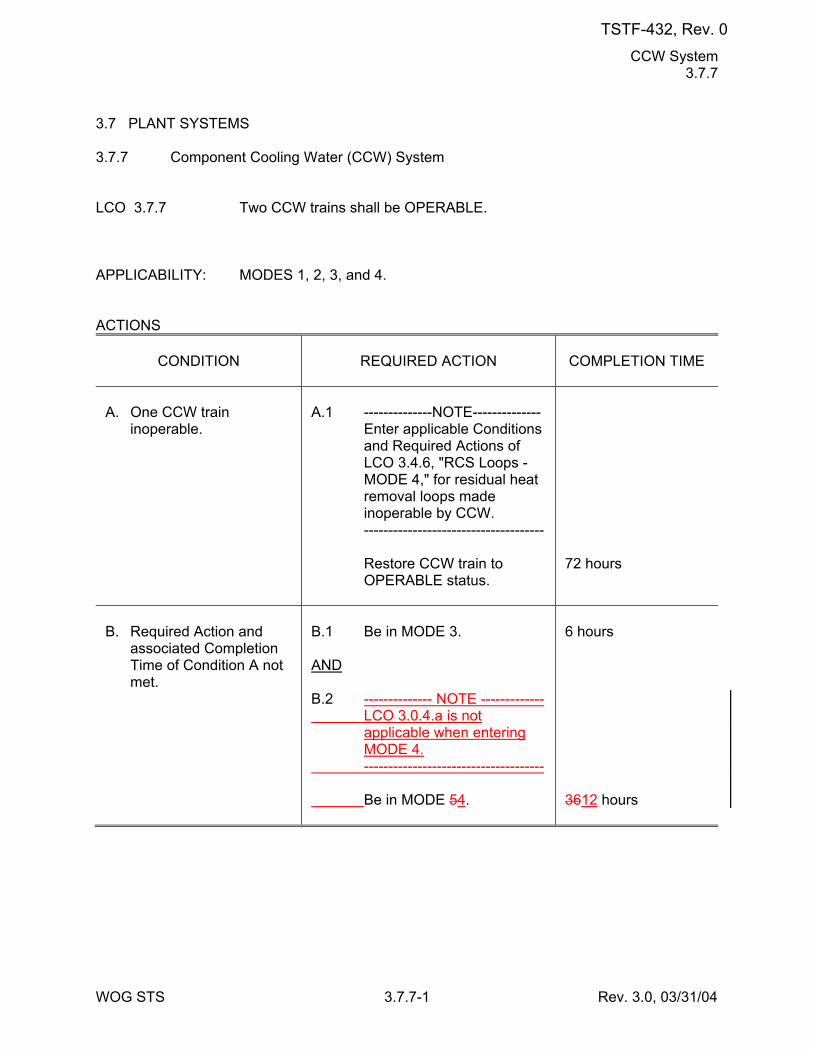
CCW System 3.7.7
WOG STS 3.7.7-1 Rev. 3.0, 03/31/04
3.7 PLANT SYSTEMS 3.7.7 Component Cooling Water (CCW) System LCO 3.7.7 Two CCW trains shall be OPERABLE. APPLICABILITY: MODES 1, 2, 3, and 4. ACTIONS
CONDITION
REQUIRED ACTION
COMPLETION TIME
A. One CCW train
inoperable.
A.1 --------------NOTE-------------- Enter applicable Conditions
and Required Actions of LCO 3.4.6, "RCS Loops - MODE 4," for residual heat removal loops made inoperable by CCW.
------------------------------------- Restore CCW train to
OPERABLE status.
72 hours
B. Required Action and
associated Completion Time of Condition A not met.
B.1 Be in MODE 3. AND B.2 -------------- NOTE ------------- LCO 3.0.4.a is not
applicable when entering MODE 4.
------------------------------------- Be in MODE 54.
6 hours 3612 hours
TSTF-432, Rev. 0
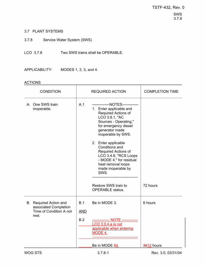
SWS 3.7.8
WOG STS 3.7.8-1 Rev. 3.0, 03/31/04
3.7 PLANT SYSTEMS 3.7.8 Service Water System (SWS) LCO 3.7.8 Two SWS trains shall be OPERABLE. APPLICABILITY: MODES 1, 2, 3, and 4. ACTIONS
CONDITION
REQUIRED ACTION
COMPLETION TIME
A. One SWS train
inoperable.
A.1 --------------NOTES------------- 1. Enter applicable and
Required Actions of LCO 3.8.1, "AC Sources - Operating," for emergency diesel generator made inoperable by SWS.
2. Enter applicable
Conditions and Required Actions of LCO 3.4.6, "RCS Loops - MODE 4," for residual heat removal loops made inoperable by SWS.
------------------------------------- Restore SWS train to
OPERABLE status.
72 hours
B. Required Action and
associated Completion Time of Condition A not met.
B.1 Be in MODE 3. AND B.2 -------------- NOTE ------------- LCO 3.0.4.a is not
applicable when entering MODE 4.
------------------------------------- Be in MODE 54.
6 hours 3612 hours
TSTF-432, Rev. 0
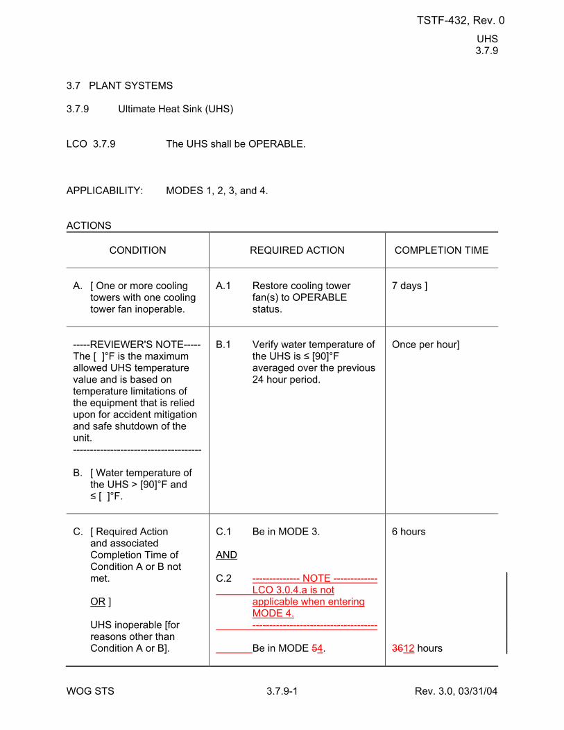
UHS 3.7.9
WOG STS 3.7.9-1 Rev. 3.0, 03/31/04
3.7 PLANT SYSTEMS 3.7.9 Ultimate Heat Sink (UHS) LCO 3.7.9 The UHS shall be OPERABLE. APPLICABILITY: MODES 1, 2, 3, and 4. ACTIONS
CONDITION
REQUIRED ACTION
COMPLETION TIME
A. [ One or more cooling
towers with one cooling tower fan inoperable.
A.1 Restore cooling tower
fan(s) to OPERABLE status.
7 days ]
-----REVIEWER'S NOTE----- The [ ]°F is the maximum allowed UHS temperature value and is based on temperature limitations of the equipment that is relied upon for accident mitigation and safe shutdown of the unit. -------------------------------------- B. [ Water temperature of
the UHS > [90]°F and ≤ [ ]°F.
B.1 Verify water temperature of
the UHS is ≤ [90]°F averaged over the previous 24 hour period.
Once per hour]
C. [ Required Action
and associated Completion Time of Condition A or B not met.
OR ] UHS inoperable [for
reasons other than Condition A or B].
C.1 Be in MODE 3. AND C.2 -------------- NOTE ------------- LCO 3.0.4.a is not
applicable when entering MODE 4.
------------------------------------- Be in MODE 54.
6 hours 3612 hours
TSTF-432, Rev. 0
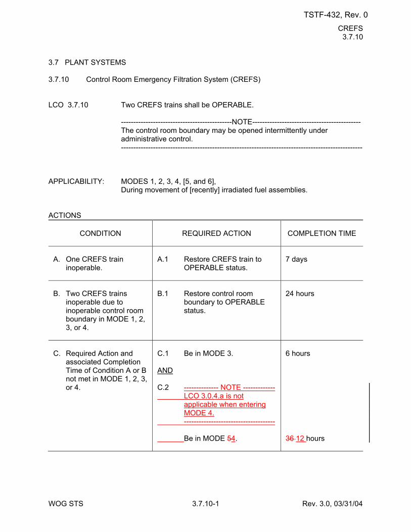
CREFS 3.7.10
WOG STS 3.7.10-1 Rev. 3.0, 03/31/04
3.7 PLANT SYSTEMS 3.7.10 Control Room Emergency Filtration System (CREFS) LCO 3.7.10 Two CREFS trains shall be OPERABLE. ---------------------------------------------NOTE-------------------------------------------- The control room boundary may be opened intermittently under
administrative control. -------------------------------------------------------------------------------------------------- APPLICABILITY: MODES 1, 2, 3, 4, [5, and 6], During movement of [recently] irradiated fuel assemblies. ACTIONS
CONDITION
REQUIRED ACTION
COMPLETION TIME
A. One CREFS train
inoperable.
A.1 Restore CREFS train to
OPERABLE status.
7 days
B. Two CREFS trains
inoperable due to inoperable control room boundary in MODE 1, 2, 3, or 4.
B.1 Restore control room
boundary to OPERABLE status.
24 hours
C. Required Action and
associated Completion Time of Condition A or B not met in MODE 1, 2, 3, or 4.
C.1 Be in MODE 3. AND C.2 -------------- NOTE ------------- LCO 3.0.4.a is not
applicable when entering MODE 4.
------------------------------------- Be in MODE 54.
6 hours 36 12 hours
TSTF-432, Rev. 0

CREATCS 3.7.11
WOG STS 3.7.11-1 Rev. 3.0, 03/31/04
3.7 PLANT SYSTEMS 3.7.11 Control Room Emergency Air Temperature Control System (CREATCS) LCO 3.7.11 Two CREATCS trains shall be OPERABLE. APPLICABILITY: MODES 1, 2, 3, 4, [5, and 6], During movement of [recently] irradiated fuel assemblies. ACTIONS
CONDITION
REQUIRED ACTION
COMPLETION TIME
A. One CREATCS train
inoperable.
A.1 Restore CREATCS train to
OPERABLE status.
30 days
B. Required Action and
associated Completion Time of Condition A not met in MODE 1, 2, 3, or 4.
B.1 Be in MODE 3. AND B.2 -------------- NOTE ------------- LCO 3.0.4.a is not
applicable when entering MODE 4.
------------------------------------- Be in MODE 54.
6 hours 36 12 hours
C. Required Action and
associated Completion Time of Condition A not met [in MODE 5 or 6, or] during movement of [recently] irradiated fuel assemblies.
C.1 Place OPERABLE
CREATCS train in operation.
OR C.2 Suspend movement of
[recently] irradiated fuel assemblies.
Immediately Immediately
D. Two CREATCS trains
inoperable [in MODE 5 or 6, or] during movement of [recently] irradiated fuel
D.1 Suspend movement of
[recently] irradiated fuel assemblies.
Immediately
TSTF-432, Rev. 0
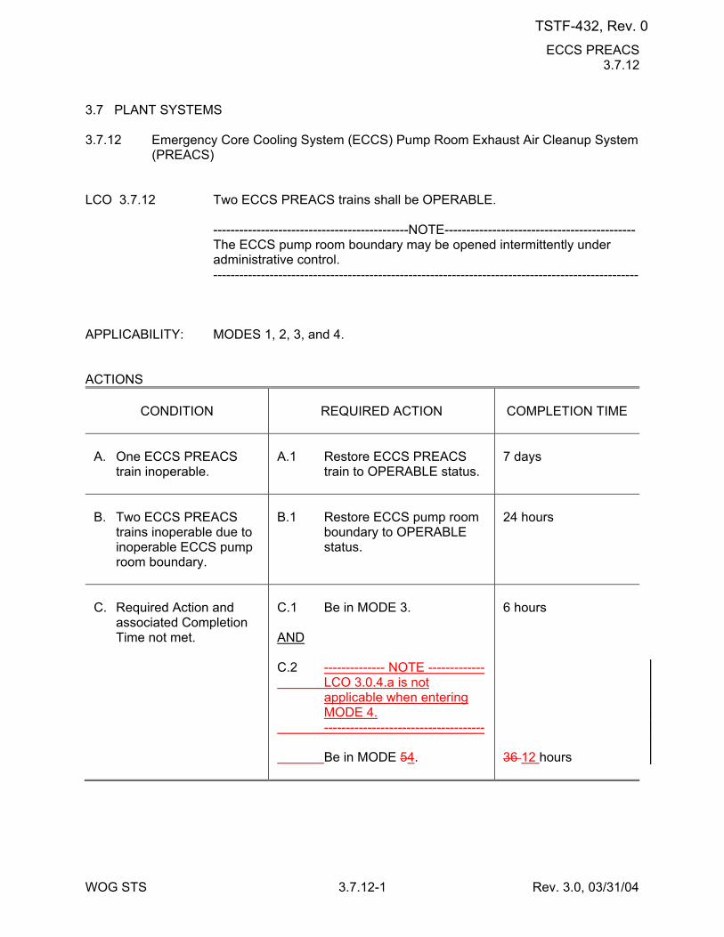
ECCS PREACS 3.7.12
WOG STS 3.7.12-1 Rev. 3.0, 03/31/04
3.7 PLANT SYSTEMS 3.7.12 Emergency Core Cooling System (ECCS) Pump Room Exhaust Air Cleanup System
(PREACS) LCO 3.7.12 Two ECCS PREACS trains shall be OPERABLE. ---------------------------------------------NOTE-------------------------------------------- The ECCS pump room boundary may be opened intermittently under
administrative control. -------------------------------------------------------------------------------------------------- APPLICABILITY: MODES 1, 2, 3, and 4. ACTIONS
CONDITION
REQUIRED ACTION
COMPLETION TIME
A. One ECCS PREACS
train inoperable.
A.1 Restore ECCS PREACS
train to OPERABLE status.
7 days
B. Two ECCS PREACS
trains inoperable due to inoperable ECCS pump room boundary.
B.1 Restore ECCS pump room
boundary to OPERABLE status.
24 hours
C. Required Action and
associated Completion Time not met.
C.1 Be in MODE 3. AND C.2 -------------- NOTE ------------- LCO 3.0.4.a is not
applicable when entering MODE 4.
------------------------------------- Be in MODE 54.
6 hours 36 12 hours
TSTF-432, Rev. 0
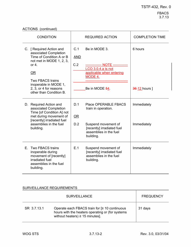
FBACS 3.7.13
WOG STS 3.7.13-2 Rev. 3.0, 03/31/04
ACTIONS (continued)
CONDITION
REQUIRED ACTION
COMPLETION TIME
C. [ Required Action and
associated Completion Time of Condition A or B not met in MODE 1, 2, 3, or 4.
OR Two FBACS trains
inoperable in MODE 1, 2, 3, or 4 for reasons other than Condition B.
C.1 Be in MODE 3. AND C.2 -------------- NOTE ------------- LCO 3.0.4.a is not
applicable when entering MODE 4.
------------------------------------- Be in MODE 54.
6 hours 36 12 hours ]
D. Required Action and
associated Completion Time [of Condition A] not met during movement of [recently] irradiated fuel assemblies in the fuel building.
D.1 Place OPERABLE FBACS
train in operation. OR D.2 Suspend movement of
[recently] irradiated fuel assemblies in the fuel building.
Immediately Immediately
E. Two FBACS trains
inoperable during movement of [recently] irradiated fuel assemblies in the fuel building.
E.1 Suspend movement of
[recently] irradiated fuel assemblies in the fuel building.
Immediately
SURVEILLANCE REQUIREMENTS
SURVEILLANCE
FREQUENCY
SR 3.7.13.1 Operate each FBACS train for [≥ 10 continuous
hours with the heaters operating or (for systems without heaters) ≥ 15 minutes].
31 days
TSTF-432, Rev. 0
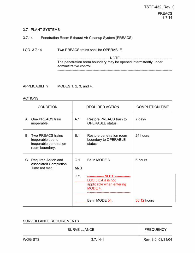
PREACS 3.7.14
WOG STS 3.7.14-1 Rev. 3.0, 03/31/04
3.7 PLANT SYSTEMS 3.7.14 Penetration Room Exhaust Air Cleanup System (PREACS) LCO 3.7.14 Two PREACS trains shall be OPERABLE. ---------------------------------------------NOTE-------------------------------------------- The penetration room boundary may be opened intermittently under
administrative control. -------------------------------------------------------------------------------------------------- APPLICABILITY: MODES 1, 2, 3, and 4. ACTIONS
CONDITION
REQUIRED ACTION
COMPLETION TIME
A. One PREACS train
inoperable.
A.1 Restore PREACS train to
OPERABLE status.
7 days
B. Two PREACS trains
inoperable due to inoperable penetration room boundary.
B.1 Restore penetration room
boundary to OPERABLE status.
24 hours
C. Required Action and
associated Completion Time not met.
C.1 Be in MODE 3. AND C.2 -------------- NOTE ------------- LCO 3.0.4.a is not
applicable when entering MODE 4.
------------------------------------- Be in MODE 54.
6 hours 36 12 hours
SURVEILLANCE REQUIREMENTS
SURVEILLANCE
FREQUENCY
TSTF-432, Rev. 0
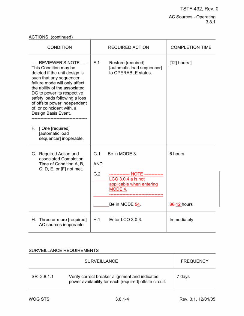
AC Sources - Operating 3.8.1
WOG STS 3.8.1-4 Rev. 3.1, 12/01/05
ACTIONS (continued)
CONDITION
REQUIRED ACTION
COMPLETION TIME
-----REVIEWER’S NOTE----- This Condition may be deleted if the unit design is such that any sequencer failure mode will only affect the ability of the associated DG to power its respective safety loads following a loss of offsite power independent of, or coincident with, a Design Basis Event. -------------------------------------- F. [ One [required]
[automatic load sequencer] inoperable.
F.1 Restore [required]
[automatic load sequencer] to OPERABLE status.
[12] hours ]
G. Required Action and
associated Completion Time of Condition A, B, C, D, E, or [F] not met.
G.1 Be in MODE 3. AND G.2 -------------- NOTE ------------- LCO 3.0.4.a is not
applicable when entering MODE 4.
------------------------------------- Be in MODE 54.
6 hours 36 12 hours
H. Three or more [required]
AC sources inoperable.
H.1 Enter LCO 3.0.3.
Immediately
SURVEILLANCE REQUIREMENTS
SURVEILLANCE
FREQUENCY
SR 3.8.1.1 Verify correct breaker alignment and indicated
power availability for each [required] offsite circuit.
7 days
TSTF-432, Rev. 0
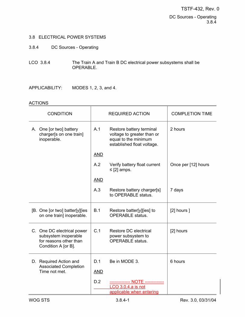
DC Sources - Operating 3.8.4
WOG STS 3.8.4-1 Rev. 3.0, 03/31/04
3.8 ELECTRICAL POWER SYSTEMS 3.8.4 DC Sources - Operating LCO 3.8.4 The Train A and Train B DC electrical power subsystems shall be
OPERABLE. APPLICABILITY: MODES 1, 2, 3, and 4. ACTIONS
CONDITION
REQUIRED ACTION
COMPLETION TIME
A. One [or two] battery
charger[s on one train] inoperable.
A.1 Restore battery terminal
voltage to greater than or equal to the minimum established float voltage.
AND A.2 Verify battery float current
≤ [2] amps. AND A.3 Restore battery charger[s]
to OPERABLE status.
2 hours Once per [12] hours 7 days
[B. One [or two] batter[y][ies
on one train] inoperable.
B.1 Restore batter[y][ies] to
OPERABLE status.
[2] hours ]
C. One DC electrical power
subsystem inoperable for reasons other than Condition A [or B].
C.1 Restore DC electrical
power subsystem to OPERABLE status.
[2] hours
D. Required Action and
Associated Completion Time not met.
D.1 Be in MODE 3. AND D.2 -------------- NOTE ------------- LCO 3.0.4.a is not
applicable when entering
6 hours
TSTF-432, Rev. 0
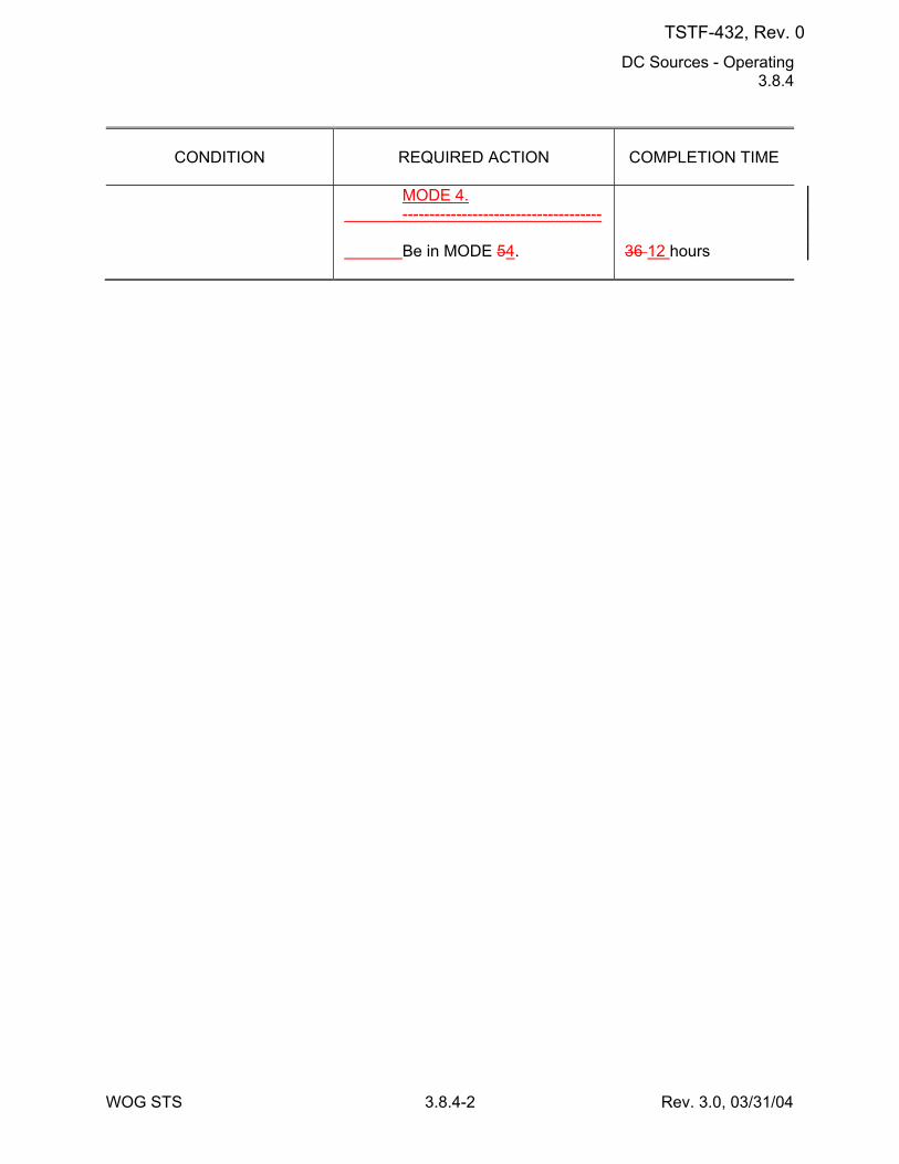
DC Sources - Operating 3.8.4
WOG STS 3.8.4-2 Rev. 3.0, 03/31/04
CONDITION
REQUIRED ACTION
COMPLETION TIME
MODE 4.
------------------------------------- Be in MODE 54.
36 12 hours
TSTF-432, Rev. 0
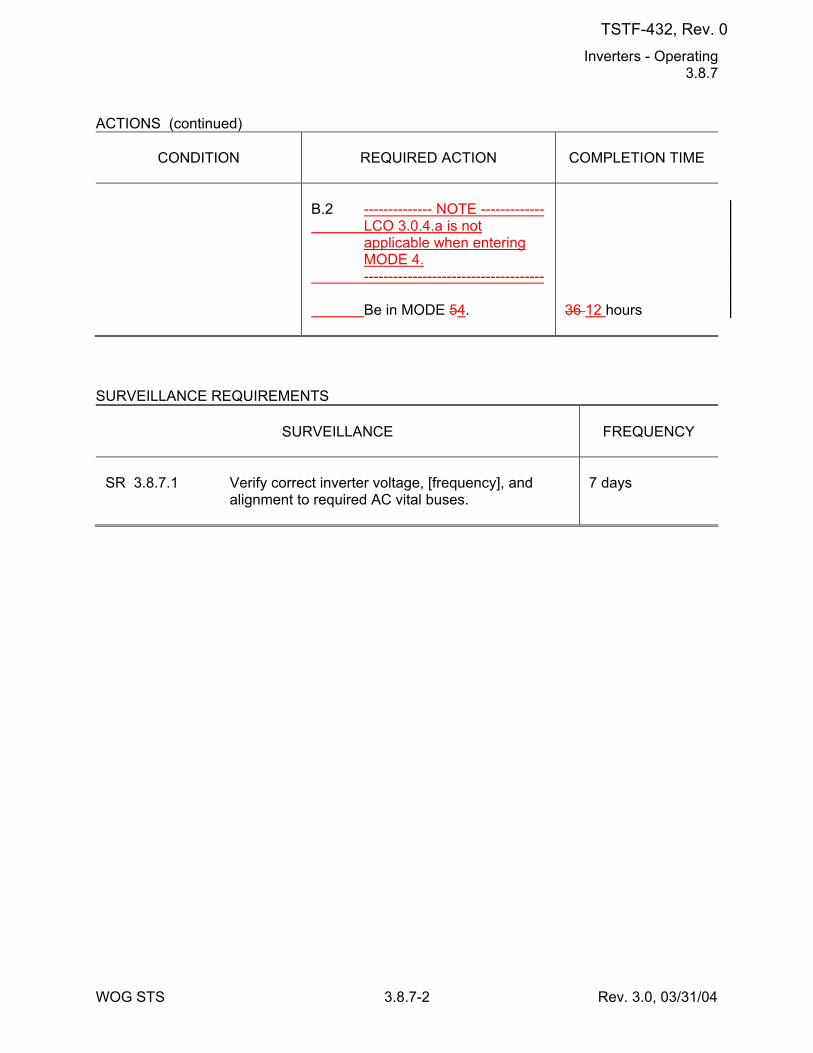
Inverters - Operating 3.8.7
WOG STS 3.8.7-2 Rev. 3.0, 03/31/04
ACTIONS (continued)
CONDITION
REQUIRED ACTION
COMPLETION TIME
B.2 -------------- NOTE ------------- LCO 3.0.4.a is not
applicable when entering MODE 4.
------------------------------------- Be in MODE 54.
36 12 hours
SURVEILLANCE REQUIREMENTS
SURVEILLANCE
FREQUENCY
SR 3.8.7.1 Verify correct inverter voltage, [frequency], and
alignment to required AC vital buses.
7 days
TSTF-432, Rev. 0
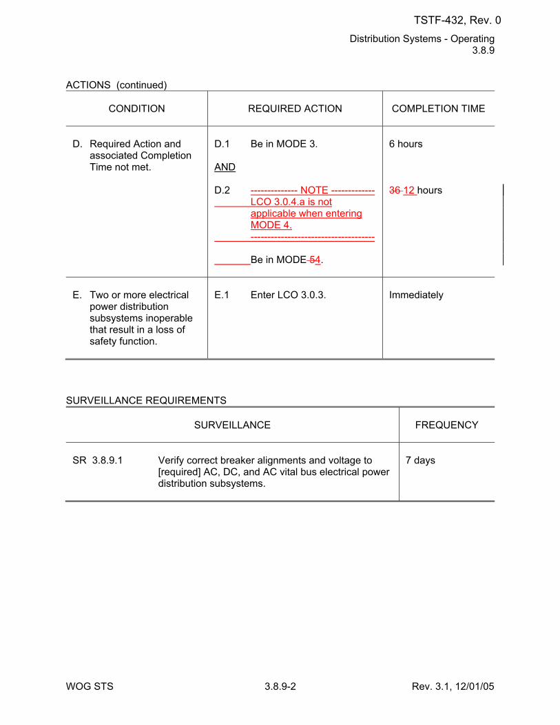
Distribution Systems - Operating 3.8.9
WOG STS 3.8.9-2 Rev. 3.1, 12/01/05
ACTIONS (continued)
CONDITION
REQUIRED ACTION
COMPLETION TIME
D. Required Action and
associated Completion Time not met.
D.1 Be in MODE 3. AND D.2 -------------- NOTE ------------- LCO 3.0.4.a is not
applicable when entering MODE 4.
------------------------------------- Be in MODE 54.
6 hours 36 12 hours
E. Two or more electrical
power distribution subsystems inoperable that result in a loss of safety function.
E.1 Enter LCO 3.0.3.
Immediately
SURVEILLANCE REQUIREMENTS
SURVEILLANCE
FREQUENCY
SR 3.8.9.1 Verify correct breaker alignments and voltage to
[required] AC, DC, and AC vital bus electrical power distribution subsystems.
7 days
TSTF-432, Rev. 0
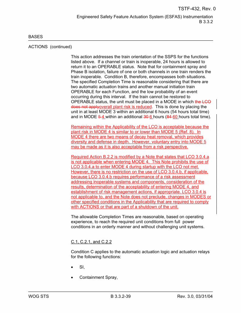
Engineered Safety Feature Actuation System (ESFAS) Instrumentation B 3.3.2
WOG STS B 3.3.2-39 Rev. 3.0, 03/31/04
BASES ACTIONS (continued)
This action addresses the train orientation of the SSPS for the functions listed above. If a channel or train is inoperable, 24 hours is allowed to return it to an OPERABLE status. Note that for containment spray and Phase B isolation, failure of one or both channels in one train renders the train inoperable. Condition B, therefore, encompasses both situations. The specified Completion Time is reasonable considering that there are two automatic actuation trains and another manual initiation train OPERABLE for each Function, and the low probability of an event occurring during this interval. If the train cannot be restored to OPERABLE status, the unit must be placed in a MODE in which the LCO does not applyoverall plant risk is reduced. This is done by placing the unit in at least MODE 3 within an additional 6 hours (54 hours total time) and in MODE 5 4 within an additional 30 6 hours (84 60 hours total time). Remaining within the Applicability of the LCO is acceptable because the plant risk in MODE 4 is similar to or lower than MODE 5 (Ref. 8). In MODE 4 there are two means of decay heat removal, which provides diversity and defense in depth. However, voluntary entry into MODE 5 may be made as it is also acceptable from a risk perspective. Required Action B.2.2 is modified by a Note that states that LCO 3.0.4.a is not applicable when entering MODE 4. This Note prohibits the use of LCO 3.0.4.a to enter MODE 4 during startup with the LCO not met. However, there is no restriction on the use of LCO 3.0.4.b, if applicable, because LCO 3.0.4.b requires performance of a risk assessment addressing inoperable systems and components, consideration of the results, determination of the acceptability of entering MODE 4, and establishment of risk management actions, if appropriate. LCO 3.0.4 is not applicable to, and the Note does not preclude, changes in MODES or other specified conditions in the Applicability that are required to comply with ACTIONS or that are part of a shutdown of the unit. The allowable Completion Times are reasonable, based on operating experience, to reach the required unit conditions from full power conditions in an orderly manner and without challenging unit systems. C.1, C.2.1, and C.2.2 Condition C applies to the automatic actuation logic and actuation relays for the following functions: • SI,
• Containment Spray,
TSTF-432, Rev. 0
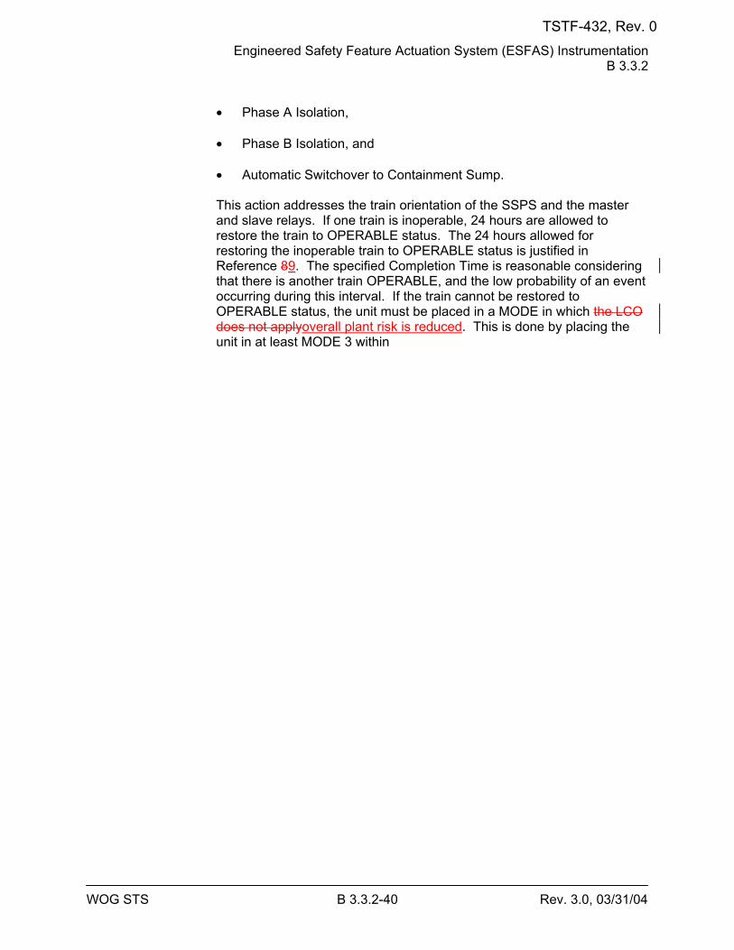
Engineered Safety Feature Actuation System (ESFAS) Instrumentation B 3.3.2
WOG STS B 3.3.2-40 Rev. 3.0, 03/31/04
• Phase A Isolation,
• Phase B Isolation, and
• Automatic Switchover to Containment Sump.
This action addresses the train orientation of the SSPS and the master and slave relays. If one train is inoperable, 24 hours are allowed to restore the train to OPERABLE status. The 24 hours allowed for restoring the inoperable train to OPERABLE status is justified in Reference 89. The specified Completion Time is reasonable considering that there is another train OPERABLE, and the low probability of an event occurring during this interval. If the train cannot be restored to OPERABLE status, the unit must be placed in a MODE in which the LCO does not applyoverall plant risk is reduced. This is done by placing the unit in at least MODE 3 within
TSTF-432, Rev. 0
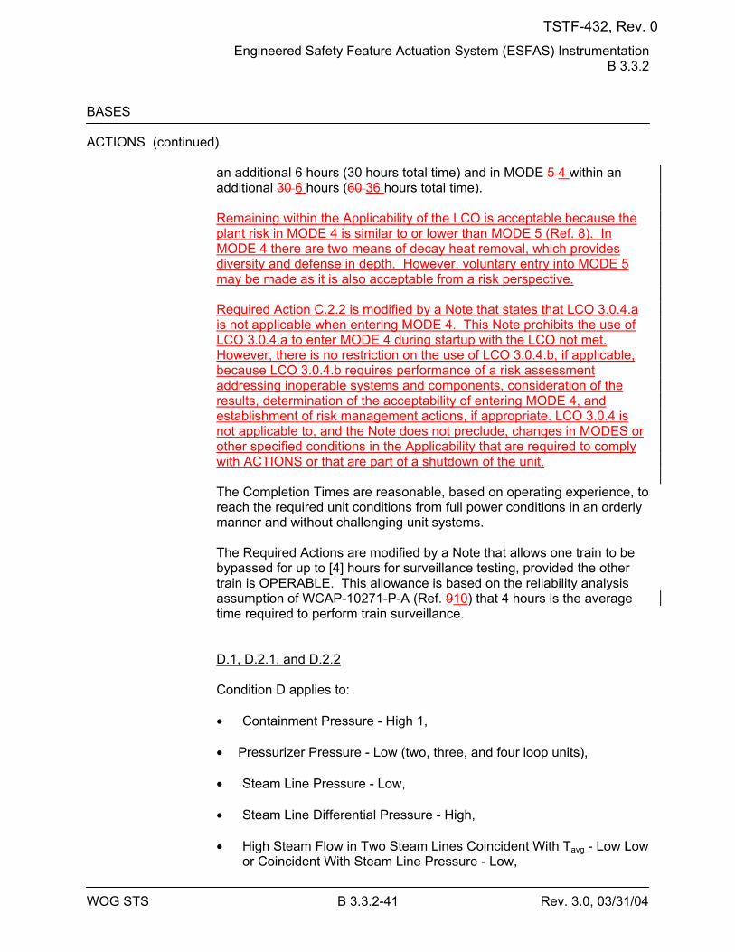
Engineered Safety Feature Actuation System (ESFAS) Instrumentation B 3.3.2
WOG STS B 3.3.2-41 Rev. 3.0, 03/31/04
BASES ACTIONS (continued)
an additional 6 hours (30 hours total time) and in MODE 5 4 within an additional 30 6 hours (60 36 hours total time). Remaining within the Applicability of the LCO is acceptable because the plant risk in MODE 4 is similar to or lower than MODE 5 (Ref. 8). In MODE 4 there are two means of decay heat removal, which provides diversity and defense in depth. However, voluntary entry into MODE 5 may be made as it is also acceptable from a risk perspective. Required Action C.2.2 is modified by a Note that states that LCO 3.0.4.a is not applicable when entering MODE 4. This Note prohibits the use of LCO 3.0.4.a to enter MODE 4 during startup with the LCO not met. However, there is no restriction on the use of LCO 3.0.4.b, if applicable, because LCO 3.0.4.b requires performance of a risk assessment addressing inoperable systems and components, consideration of the results, determination of the acceptability of entering MODE 4, and establishment of risk management actions, if appropriate. LCO 3.0.4 is not applicable to, and the Note does not preclude, changes in MODES or other specified conditions in the Applicability that are required to comply with ACTIONS or that are part of a shutdown of the unit. The Completion Times are reasonable, based on operating experience, to reach the required unit conditions from full power conditions in an orderly manner and without challenging unit systems. The Required Actions are modified by a Note that allows one train to be bypassed for up to [4] hours for surveillance testing, provided the other train is OPERABLE. This allowance is based on the reliability analysis assumption of WCAP-10271-P-A (Ref. 910) that 4 hours is the average time required to perform train surveillance. D.1, D.2.1, and D.2.2 Condition D applies to: • Containment Pressure - High 1,
• Pressurizer Pressure - Low (two, three, and four loop units),
• Steam Line Pressure - Low,
• Steam Line Differential Pressure - High,
• High Steam Flow in Two Steam Lines Coincident With Tavg - Low Low
or Coincident With Steam Line Pressure - Low,
TSTF-432, Rev. 0
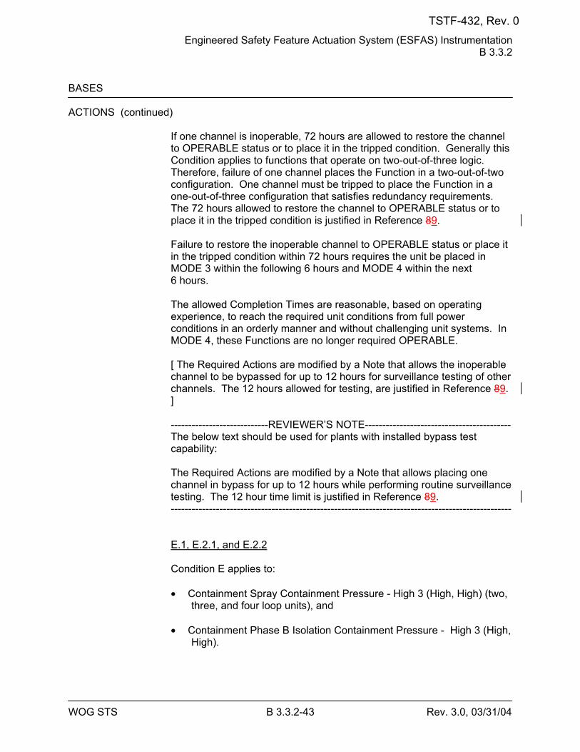
Engineered Safety Feature Actuation System (ESFAS) Instrumentation B 3.3.2
WOG STS B 3.3.2-43 Rev. 3.0, 03/31/04
BASES ACTIONS (continued)
If one channel is inoperable, 72 hours are allowed to restore the channel to OPERABLE status or to place it in the tripped condition. Generally this Condition applies to functions that operate on two-out-of-three logic. Therefore, failure of one channel places the Function in a two-out-of-two configuration. One channel must be tripped to place the Function in a one-out-of-three configuration that satisfies redundancy requirements. The 72 hours allowed to restore the channel to OPERABLE status or to place it in the tripped condition is justified in Reference 89. Failure to restore the inoperable channel to OPERABLE status or place it in the tripped condition within 72 hours requires the unit be placed in MODE 3 within the following 6 hours and MODE 4 within the next 6 hours. The allowed Completion Times are reasonable, based on operating experience, to reach the required unit conditions from full power conditions in an orderly manner and without challenging unit systems. In MODE 4, these Functions are no longer required OPERABLE. [ The Required Actions are modified by a Note that allows the inoperable channel to be bypassed for up to 12 hours for surveillance testing of other channels. The 12 hours allowed for testing, are justified in Reference 89. ] ----------------------------REVIEWER’S NOTE------------------------------------------ The below text should be used for plants with installed bypass test capability: The Required Actions are modified by a Note that allows placing one channel in bypass for up to 12 hours while performing routine surveillance testing. The 12 hour time limit is justified in Reference 89. -------------------------------------------------------------------------------------------------- E.1, E.2.1, and E.2.2 Condition E applies to:
• Containment Spray Containment Pressure - High 3 (High, High) (two,
three, and four loop units), and
• Containment Phase B Isolation Containment Pressure - High 3 (High, High).
TSTF-432, Rev. 0
Engineered Safety Feature Actuation System (ESFAS) Instrumentation B 3.3.2
WOG STS B 3.3.2-44 Rev. 3.0, 03/31/04
BASES ACTIONS (continued)
None of these signals has input to a control function. Thus, two-out-of-three logic is necessary to meet acceptable protective requirements. However, a two-out-of-three design would require tripping a failed channel. This is undesirable because a single failure would then cause spurious containment spray initiation. Spurious spray actuation is undesirable because of the cleanup problems presented. Therefore, these channels are designed with two-out-of-four logic so that a failed channel may be bypassed rather than tripped. Note that one channel may be bypassed and still satisfy the single failure criterion. Furthermore, with one channel bypassed, a single instrumentation channel failure will not spuriously initiate containment spray. To avoid the inadvertent actuation of containment spray and Phase B containment isolation, the inoperable channel should not be placed in the tripped condition. Instead it is bypassed. Restoring the channel to OPERABLE status, or placing the inoperable channel in the bypass condition within 72 hours, is sufficient to assure that the Function remains OPERABLE and minimizes the time that the Function may be in a partial trip condition (assuming the inoperable channel has failed high). The Completion Time is further justified based on the low probability of an event occurring during this interval. Failure to restore the inoperable channel to OPERABLE status, or place it in the bypassed condition within 6 hours, requires the unit be placed in MODE 3 within the following 6 hours and MODE 4 within the next 72 hours. The allowed Completion Times are reasonable, based on operating experience, to reach the required unit conditions from full power conditions in an orderly manner and without challenging unit systems. In MODE 4, these Functions are no longer required OPERABLE. [ The Required Actions are modified by a Note that allows one additional channel to be bypassed for up to 12 hours for surveillance testing. Placing a second channel in the bypass condition for up to 12 hours for testing purposes is acceptable based on the results of Reference 89. ] ----------------------------REVIEWER’S NOTE------------------------------------------ The below text should be used for plants with installed bypass test capability: The Required Actions are modified by a Note that allows placing one channel in bypass for up to 12 hours while performing routine surveillance testing. The 12 hour time limit is justified in Reference 89. --------------------------------------------------------------------------------------------------
TSTF-432, Rev. 0
Engineered Safety Feature Actuation System (ESFAS) Instrumentation B 3.3.2
WOG STS B 3.3.2-46 Rev. 3.0, 03/31/04
BASES ACTIONS (continued)
The action addresses the train orientation of the SSPS and the master and slave relays for these functions. If one train is inoperable, 24 hours are allowed to restore the train to OPERABLE status. The 24 hours allowed for restoring the inoperable train to OPERABLE status is justified in Reference 89. The Completion Time for restoring a train to OPERABLE status is reasonable considering that there is another train OPERABLE, and the low probability of an event occurring during this interval. If the train cannot be returned to OPERABLE status, the unit must be brought to MODE 3 within the next 6 hours and MODE 4 within the following 6 hours. The allowed Completion Times are reasonable, based on operating experience, to reach the required unit conditions from full power conditions in an orderly manner and without challenging unit systems. Placing the unit in MODE 4 removes all requirements for OPERABILITY of the protection channels and actuation functions. In this MODE, the unit does not have analyzed transients or conditions that require the explicit use of the protection functions noted above. The Required Actions are modified by a Note that allows one train to be bypassed for up to [4] hours for surveillance testing provided the other train is OPERABLE. This allowance is based on the reliability analysis (Ref. 910) assumption that 4 hours is the average time required to perform channel surveillance.
[ H.1 and H.2 Condition H applies to the automatic actuation logic and actuation relays for the Turbine Trip and Feedwater Isolation Function. This action addresses the train orientation of the SSPS and the master and slave relays for this Function. If one train is inoperable, 24 hours are allowed to restore the train to OPERABLE status or the unit must be placed in MODE 3 within the following 6 hours. The 24 hours allowed for restoring the inoperable train to OPERABLE status is justified in Reference 89. The Completion Time for restoring a train to OPERABLE status is reasonable considering that there is another train OPERABLE, and the low probability of an event occurring during this interval. The allowed Completion Time of 6 hours is reasonable, based on operating experience, to reach MODE 3 from full power conditions in an orderly manner and without challenging unit systems. These Functions are no longer required in MODE 3. Placing the unit in MODE 3 removes all requirements for OPERABILITY of the protection channels and actuation functions. In this MODE, the unit does not have analyzed transients or conditions that require the explicit use of the protection functions noted above.
TSTF-432, Rev. 0
Engineered Safety Feature Actuation System (ESFAS) Instrumentation B 3.3.2
WOG STS B 3.3.2-47 Rev. 3.0, 03/31/04
BASES ACTIONS (continued)
The Required Actions are modified by a Note that allows one train to be bypassed for up to [4] hours for surveillance testing provided the other train is OPERABLE. This allowance is based on the reliability analysis (Ref. 910) assumption that 4 hours is the average time required to perform channel surveillance. ] I.1 and I.2 Condition I applies to:
• [ SG Water Level - High High (P-14) (two, three, and four loop units),
and ]
• Undervoltage Reactor Coolant Pump. If one channel is inoperable, 72 hours are allowed to restore one channel to OPERABLE status or to place it in the tripped condition. If placed in the tripped condition, the Function is then in a partial trip condition where one-out-of-two or one-out-of-three logic will result in actuation. Failure to restore the inoperable channel to OPERABLE status or place it in the tripped condition within 72 hours requires the unit to be placed in MODE 3 within the following 6 hours. The allowed Completion Time of 78 hours is reasonable, based on operating experience, to reach MODE 3 from full power conditions in an orderly manner and without challenging unit systems. In MODE 3, these Functions are no longer required OPERABLE. [ The Required Actions are modified by a Note that allows the inoperable channel to be bypassed for up to [12] hours for surveillance testing of other channels. The 72 hours allowed to place the inoperable channel in the tripped condition, and the 12 hours allowed for a second channel to be in the bypassed condition for testing, are justified in Reference 89. ] ----------------------------REVIEWER’S NOTE------------------------------------------ The below text should be used for plants with installed bypass test capability: The Required Actions are modified by a Note that allows placing one channel in bypass for up to 12 hours while performing routine surveillance testing. The 72 hours allowed to place the inoperable channel in the tripped condition, and the 12 hours allowed for a second channel to be in the bypassed condition for testing, are justified in Reference 89. --------------------------------------------------------------------------------------------------
TSTF-432, Rev. 0
Engineered Safety Feature Actuation System (ESFAS) Instrumentation B 3.3.2
WOG STS B 3.3.2-48 Rev. 3.0, 03/31/04
BASES ACTIONS (continued)
J.1 and J.2 Condition J applies to the AFW pump start on trip of all MFW pumps. 88This action addresses the train orientation of the SSPS for the auto start function of the AFW System on loss of all MFW pumps. The OPERABILITY of the AFW System must be assured by allowing automatic start of the AFW System pumps. If a channel is inoperable, 48 hours are allowed to return it to an OPERABLE status. If the function cannot be returned to an OPERABLE status, 6 hours are allowed to place the unit in MODE 3. The allowed Completion Time of 6 hours is reasonable, based on operating experience, to reach MODE 3 from full power conditions in an orderly manner and without challenging unit systems. In MODE 3, the unit does not have any analyzed transients or conditions that require the explicit use of the protection function noted above. The allowance of 48 hours to return the train to an OPERABLE status is justified in Reference 910. K.1, K.2.1, and K.2.2
Condition K applies to:
• RWST Level - Low Low Coincident with Safety Injection, and
• RWST Level - Low Low Coincident with Safety Injection and
Coincident with Containment Sump Level - High.
RWST Level - Low Low Coincident With SI and Coincident With Containment Sump Level - High provides actuation of switchover to the containment sump. Note that this Function requires the bistables to energize to perform their required action. The failure of up to two channels will not prevent the operation of this Function. However, placing a failed channel in the tripped condition could result in a premature switchover to the sump, prior to the injection of the minimum volume from the RWST. Placing the inoperable channel in bypass results in a two-out-of-three logic configuration, which satisfies the requirement to allow another failure without disabling actuation of the switchover when required. Restoring the channel to OPERABLE status or placing the inoperable channel in the bypass condition within [6] hours is sufficient to ensure that the Function remains OPERABLE, and minimizes the time that the Function may be in a partial trip condition (assuming the
TSTF-432, Rev. 0
Engineered Safety Feature Actuation System (ESFAS) Instrumentation B 3.3.2
WOG STS B 3.3.2-49 Rev. 3.0, 03/31/04
BASES ACTIONS (continued)
inoperable channel has failed high). The [6] hour Completion Time is justified in Reference 1011. If the channel cannot be returned to OPERABLE status or placed in the bypass condition within 6 hours, the unit must be brought toplaced in a MODE in which overall plant risk is reduced. This is done by placing the unit in at least MODE 3 within the following [6] hours and MODE 5 4 within the next 30 6 hours. Remaining within the Applicability of the LCO is acceptable because the plant risk in MODE 4 is similar to or lower than MODE 5 (Ref. 8). In MODE 4 there are two means of decay heat removal, which provides diversity and defense in depth. However, voluntary entry into MODE 5 may be made as it is also acceptable from a risk perspective. Required Action K.2.2 is modified by a Note that states that LCO 3.0.4.a is not applicable when entering MODE 4. This Note prohibits the use of LCO 3.0.4.a to enter MODE 4 during startup with the LCO not met. However, there is no restriction on the use of LCO 3.0.4.b, if applicable, because LCO 3.0.4.b requires performance of a risk assessment addressing inoperable systems and components, consideration of the results, determination of the acceptability of entering MODE 4, and establishment of risk management actions, if appropriate. LCO 3.0.4 is not applicable to, and the Note does not preclude, changes in MODES or other specified conditions in the Applicability that are required to comply with ACTIONS or that are part of a shutdown of the unit. The allowed Completion Times are reasonable, based on operating experience, to reach the required unit conditions from full power conditions in an orderly manner and without challenging unit systems. In MODE 5, the unit does not have any analyzed transients or conditions that require the explicit use of the protection functions noted above. [ The Required Actions are modified by a Note that allows placing a second channel in the bypass condition for up to [4] hours for surveillance testing. The total of [12] hours to reach MODE 3 and [4] hours for a second channel to be bypassed is acceptable based on the results of Reference 1011.] ----------------------------REVIEWER’S NOTE------------------------------------------ The below text should be used for plants with installed bypass test capability: The Required Actions are modified by a Note that allows placing one channel in bypass for up to 12 hours while performing routine surveillance testing. The channel to be tested can be tested in bypass with the inoperable channel also in bypass. The total of [12] hours to reach MODE 3 and [4] hours for a second channel to be bypassed is acceptable based on the results of Reference 1011. --------------------------------------------------------------------------------------------------
TSTF-432, Rev. 0
Engineered Safety Feature Actuation System (ESFAS) Instrumentation B 3.3.2
WOG STS B 3.3.2-52 Rev. 3.0, 03/31/04
BASES SURVEILLANCE REQUIREMENTS (continued)
Agreement criteria are determined by the unit staff, based on a combination of the channel instrument uncertainties, including indication and reliability. If a channel is outside the criteria, it may be an indication that the sensor or the signal processing equipment has drifted outside its limit. The Frequency is based on operating experience that demonstrates channel failure is rare. The CHANNEL CHECK supplements less formal, but more frequent, checks of channels during normal operational use of the displays associated with the LCO required channels. SR 3.3.2.2 SR 3.3.2.2 is the performance of an ACTUATION LOGIC TEST. The SSPS is tested every 92 days on a STAGGERED TEST BASIS, using the semiautomatic tester. The train being tested is placed in the bypass condition, thus preventing inadvertent actuation. Through the semiautomatic tester, all possible logic combinations, with and without applicable permissives, are tested for each protection function. In addition, the master relay coil is pulse tested for continuity. This verifies that the logic modules are OPERABLE and that there is an intact voltage signal path to the master relay coils. The Frequency of every 92 days on a STAGGERED TEST BASIS is justified in Reference 1112. SR 3.3.2.3 SR 3.3.2.3 is the performance of an ACTUATION LOGIC TEST as described in SR 3.3.2.2, except that the semiautomatic tester is not used and the continuity check does not have to be performed, as explained in the Note. This SR is applied to the balance of plant actuation logic and relays that do not have the SSPS test circuits installed to utilize the semiautomatic tester or perform the continuity check. This test is also performed every 31 days on a STAGGERED TEST BASIS. The Frequency is adequate based on industry operating experience, considering instrument reliability and operating history data.
TSTF-432, Rev. 0
Engineered Safety Feature Actuation System (ESFAS) Instrumentation B 3.3.2
WOG STS B 3.3.2-53 Rev. 3.0, 03/31/04
BASES SURVEILLANCE REQUIREMENTS (continued)
SR 3.3.2.4 SR 3.3.2.4 is the performance of a MASTER RELAY TEST. The MASTER RELAY TEST is the energizing of the master relay, verifying contact operation and a low voltage continuity check of the slave relay coil. Upon master relay contact operation, a low voltage is injected to the slave relay coil. This voltage is insufficient to pick up the slave relay, but large enough to demonstrate signal path continuity. This test is performed every 92 days on a STAGGERED TEST BASIS. The time allowed for the testing (4 hours) is justified in Reference 1112. The Frequency of 92 days is justified in Reference 910. SR 3.3.2.5 SR 3.3.2.5 is the performance of a COT. A COT is performed on each required channel to ensure the entire channel will perform the intended Function. Setpoints must be found within the Allowable Values specified in Table 3.3.1-1. A successful test of the required contact(s) of a channel relay may be performed by the verification of the change of state of a single contact of the relay. This clarifies what is an acceptable COT of a relay. This is acceptable because all of the other required contacts of the relay are verified by other Technical Specifications and non-Technical Specifications tests at least once per refueling interval with applicable extensions. The difference between the current "as found" values and the previous test "as left" values must be consistent with the drift allowance used in the setpoint methodology. The setpoint shall be left set consistent with the assumptions of the current unit specific setpoint methodology. The "as found" and "as left" values must also be recorded and reviewed for consistency with the assumptions of Reference 6. The Frequency of 184 days is justified in Reference 1112.
TSTF-432, Rev. 0
Engineered Safety Feature Actuation System (ESFAS) Instrumentation B 3.3.2
WOG STS B 3.3.2-56 Rev. 3.0, 03/31/04
BASES SURVEILLANCE REQUIREMENTS (continued)
SR 3.3.2.10 This SR ensures the individual channel ESF RESPONSE TIMES are less than or equal to the maximum values assumed in the accident analysis. Response Time testing acceptance criteria are included in the Technical Requirements Manual, Section 15 (Ref. 1213). Individual component response times are not modeled in the analyses. The analyses model the overall or total elapsed time, from the point at which the parameter exceeds the Trip Setpoint value at the sensor, to the point at which the equipment in both trains reaches the required functional state (e.g., pumps at rated discharge pressure, valves in full open or closed position). For channels that include dynamic transfer functions (e.g., lag, lead/lag, rate/lag, etc.), the response time test may be performed with the transfer functions set to one with the resulting measured response time compared to the appropriate FSAR response time. Alternately, the response time test can be performed with the time constants set to their nominal value provided the required response time is analytically calculated assuming the time constants are set at their nominal values. The response time may be measured by a series of overlapping tests such that the entire response time is measured.
-----------------------------REVIEWER’S NOTE----------------------------------------- Applicable portions of the following Bases are applicable for plants adopting WCAP-13632-P-A (Ref. 910). and/or WCAP-14036-P (Ref. 1011).
-------------------------------------------------------------------------------------------------- Response time may be verified by actual response time tests in any series of sequential, overlapping or total channel measurements, or by the summation of allocated sensor, signal processing and actuation logic response times with actual response time tests on the remainder of the channel. Allocations for sensor response times may be obtained from: (1) historical records based on acceptable response time tests (hydraulic, noise, or power interrupt tests), (2) in place, onsite, or offsite (e.g., vendor) test measurements, or (3) utilizing vendor engineering specifications. WCAP-13632-P-A, Revision 2, "Elimination of Pressure Sensor Response Time Testing Requirements," (Ref. 1314) dated January 1996, provides the basis and methodology for using allocated sensor response times in the overall verification of the channel response time for specific sensors identified in the WCAP. Response time verification for other sensor types must be demonstrated by test.
TSTF-432, Rev. 0
Engineered Safety Feature Actuation System (ESFAS) Instrumentation B 3.3.2
WOG STS B 3.3.2-57 Rev. 3.0, 03/31/04
BASES SURVEILLANCE REQUIREMENTS (continued)
WCAP-14036-P, Revision 1, "Elimination of Periodic Protection Channel Response Time Tests," (Ref. 1415) provides the basis and methodology for using allocated signal processing and actuation logic response times in the overall verification of the protection system channel response time. The allocations for sensor, signal conditioning, and actuation logic response times must be verified prior to placing the component in operational service and re-verified following maintenance that may adversely affect response time. In general, electrical repair work does not impact response time provided the parts used for repair are of the same type and value. Specific components identified in the WCAP may be replaced without verification testing. One example where response time could be affected is replacing the sensing assembly of a transmitter. ESF RESPONSE TIME tests are conducted on an [18] month STAGGERED TEST BASIS. Testing of the final actuation devices, which make up the bulk of the response time, is included in the testing of each channel. The final actuation device in one train is tested with each channel. Therefore, staggered testing results in response time verification of these devices every [18] months. The [18] month Frequency is consistent with the typical refueling cycle and is based on unit operating experience, which shows that random failures of instrumentation components causing serious response time degradation, but not channel failure, are infrequent occurrences. This SR is modified by a Note that clarifies that the turbine driven AFW pump is tested within 24 hours after reaching [1000] psig in the SGs. SR 3.3.2.11 SR 3.3.2.11 is the performance of a TADOT as described in SR 3.3.2.8, except that it is performed for the P-4 Reactor Trip Interlock, and the Frequency is once per RTB cycle. A successful test of the required contact(s) of a channel relay may be performed by the verification of the change of state of a single contact of the relay. This clarifies what is an acceptable TADOT of a relay. This is acceptable because all of the other required contacts of the relay are verified by other Technical Specifications and non-Technical Specifications tests at least once per refueling interval with applicable extensions. This Frequency is based on operating experience demonstrating that undetected failure of the P-4 interlock sometimes occurs when the RTB is cycled. The SR is modified by a Note that excludes verification of setpoints during the TADOT. The Function tested has no associated setpoint.
TSTF-432, Rev. 0
Engineered Safety Feature Actuation System (ESFAS) Instrumentation B 3.3.2
WOG STS B 3.3.2-58 Rev. 3.0, 03/31/04
BASES REFERENCES 1. FSAR, Chapter [6]. 2. FSAR, Chapter [7]. 3. FSAR, Chapter [15]. 4. IEEE-279-1971. 5. 10 CFR 50.49. 6. Plant-specific setpoint methodology study. 7. NUREG-1218, April 1988. 8. WCAP-16294-NP-A, Rev. 1, "Risk-Informed Evaluation of Changes
to Technical Specification Required Action Endstates for Westinghouse NSSS PWRs," [DATE].
89. WCAP-14333-P-A, Rev. 1, October 1998. 910. WCAP-10271-P-A, Supplement 2, Rev. 1, June 1990. 1011. [Plant specific evaluation reference.] 1112. WCAP-15376, Rev. 0. October 2000. 1213. Technical Requirements Manual, Section 15, "Response Times." 1314. WCAP-13632-P-A, Revision 2, "Elimination of Pressure
Sensor Response Time Testing Requirements," January 1996.
1415. WCAP-14036-P, Revision 1, "Elimination of Periodic Protection Channel Response Time Tests," December 1995.
TSTF-432, Rev. 0
CREFS Actuation Instrumentation B 3.3.7
WOG STS B 3.3.7-5 Rev. 3.0, 03/31/04
BASES ACTIONS (continued)
C.1 and C.2 Condition C applies when the Required Action and associated Completion Time for Condition A or B have not been met and the unit is in MODE 1, 2, 3, or 4. The unit must be brought to a MODE in which the LCO requirements are not applicableoverall plant risk is reduced. To achieve this status, the unit must be brought to MODE 3 within 6 hours and MODE 5 4 within 36 12 hours. Remaining within the Applicability of the LCO is acceptable because the plant risk in MODE 4 is similar to or lower than MODE 5 (Ref. 1). In MODE 4 there are two means of decay heat removal, which provides diversity and defense in depth. However, voluntary entry into MODE 5 may be made as it is also acceptable from a risk perspective. Required Action C.2 is modified by a Note that states that LCO 3.0.4.a is not applicable when entering MODE 4. This Note prohibits the use of LCO 3.0.4.a to enter MODE 4 during startup with the LCO not met. However, there is no restriction on the use of LCO 3.0.4.b, if applicable, because LCO 3.0.4.b requires performance of a risk assessment addressing inoperable systems and components, consideration of the results, determination of the acceptability of entering MODE 4, and establishment of risk management actions, if appropriate. LCO 3.0.4 is not applicable to, and the Note does not preclude, changes in MODES or other specified conditions in the Applicability that are required to comply with ACTIONS or that are part of a shutdown of the unit. The allowed Completion Times are reasonable, based on operating experience, to reach the required unit conditions from full power conditions in an orderly manner and without challenging unit systems. D.1 Condition D applies when the Required Action and associated Completion Time for Condition A or B have not been met when [recently] irradiated fuel assemblies are being moved. Movement of [recently] irradiated fuel assemblies must be suspended immediately to reduce the risk of accidents that would require CREFS actuation. E.1 Condition E applies when the Required Action and associated Completion Time for Condition A or B have not been met in MODE 5 or 6. Actions must be initiated to restore the inoperable train(s) to OPERABLE status
TSTF-432, Rev. 0
CREFS Actuation Instrumentation B 3.3.7
WOG STS B 3.3.7-8 Rev. 3.0, 03/31/04
BASES SURVEILLANCE REQUIREMENTS (continued)
SR 3.3.7.4 SR 3.3.7.4 is the performance of a MASTER RELAY TEST. The MASTER RELAY TEST is the energizing of the master relay, verifying contact operation and a low voltage continuity check of the slave relay coil. Upon master relay contact operation, a low voltage is injected to the slave relay coil. This voltage is insufficient to pick up the slave relay, but large enough to demonstrate signal path continuity. This test is performed every 31 days on a STAGGERED TEST BASIS. The Frequency is acceptable based on instrument reliability and industry operating experience. [ SR 3.3.7.5 SR 3.3.7.5 is the performance of an ACTUATION LOGIC TEST. The train being tested is placed in the bypass condition, thus preventing inadequate actuation. Through the semiautomatic tester, all possible logic combinations, with and without applicable permissives, are tested for each protection function. In addition, the master relay coil is pulse tested for continuity. This verifies that the logic modules are OPERABLE and there is an intact voltage signal path to the master relay coils. This test is performed ever 92 days on a STAGGERED TEST BASIS. The Surveillance interval is justified in Reference 12. The SR is modified by a Note stating that the Surveillance is only applicable to the actuation logic of the ESFAS Instrumentation. ] [ SR 3.3.7.6 SR 3.3.7.6 is the performance of a MASTER RELAY TEST. The MASTER RELAY TEST is the energizing of the master relay, verifying contact operation and a low voltage continuity check of the slave relay coil. Upon master relay contact operation, a low voltage is injected to the slave relay coil. This voltage is insufficient to pick up the slave relay, but large enough to demonstrate signal path continuity. This test is performed every 92 days on a STAGGERED TEST BASIS. The Surveillance interval is justified in Reference 12. The SR is modified by a Note stating that the Surveillance is only applicable to the master relays of the ESFAS Instrumentation. ]
TSTF-432, Rev. 0
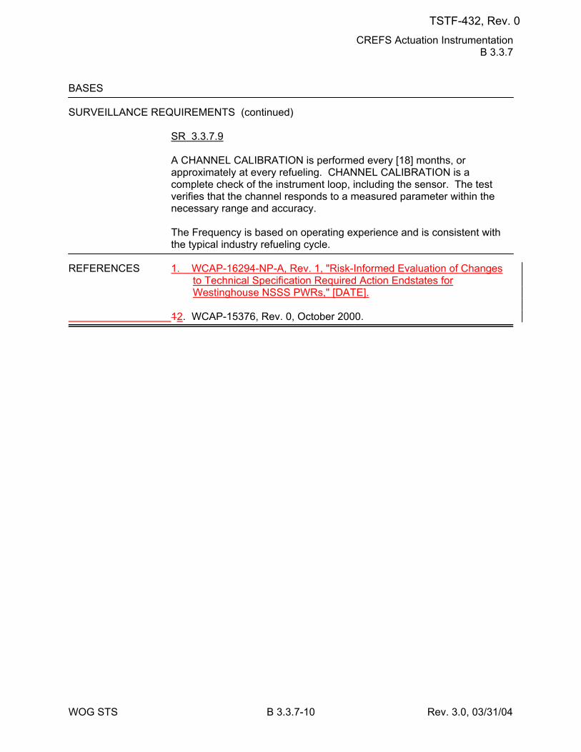
CREFS Actuation Instrumentation B 3.3.7
WOG STS B 3.3.7-10 Rev. 3.0, 03/31/04
BASES SURVEILLANCE REQUIREMENTS (continued)
SR 3.3.7.9 A CHANNEL CALIBRATION is performed every [18] months, or approximately at every refueling. CHANNEL CALIBRATION is a complete check of the instrument loop, including the sensor. The test verifies that the channel responds to a measured parameter within the necessary range and accuracy. The Frequency is based on operating experience and is consistent with the typical industry refueling cycle.
REFERENCES 1. WCAP-16294-NP-A, Rev. 1, "Risk-Informed Evaluation of Changes
to Technical Specification Required Action Endstates for Westinghouse NSSS PWRs," [DATE].
12. WCAP-15376, Rev. 0, October 2000.
TSTF-432, Rev. 0
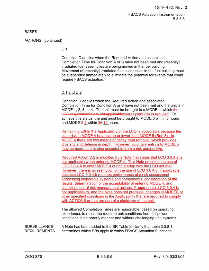
FBACS Actuation Instrumentation B 3.3.8
WOG STS B 3.3.8-5 Rev. 3.0, 03/31/04
BASES ACTIONS (continued)
C.1 Condition C applies when the Required Action and associated Completion Time for Condition A or B have not been met and [recently] irradiated fuel assemblies are being moved in the fuel building. Movement of [recently] irradiated fuel assemblies in the fuel building must be suspended immediately to eliminate the potential for events that could require FBACS actuation. D.1 and D.2 Condition D applies when the Required Action and associated Completion Time for Condition A or B have not been met and the unit is in MODE 1, 2, 3, or 4. The unit must be brought to a MODE in which the LCO requirements are not applicableoverall plant risk is reduced. To achieve this status, the unit must be brought to MODE 3 within 6 hours and MODE 5 4 within 36 12 hours. Remaining within the Applicability of the LCO is acceptable because the plant risk in MODE 4 is similar to or lower than MODE 5 (Ref. 3). In MODE 4 there are two means of decay heat removal, which provides diversity and defense in depth. However, voluntary entry into MODE 5 may be made as it is also acceptable from a risk perspective. Required Action D.2 is modified by a Note that states that LCO 3.0.4.a is not applicable when entering MODE 4. This Note prohibits the use of LCO 3.0.4.a to enter MODE 4 during startup with the LCO not met. However, there is no restriction on the use of LCO 3.0.4.b, if applicable, because LCO 3.0.4.b requires performance of a risk assessment addressing inoperable systems and components, consideration of the results, determination of the acceptability of entering MODE 4, and establishment of risk management actions, if appropriate. LCO 3.0.4 is not applicable to, and the Note does not preclude, changes in MODES or other specified conditions in the Applicability that are required to comply with ACTIONS or that are part of a shutdown of the unit. The allowed Completion Times are reasonable, based on operating experience, to reach the required unit conditions from full power conditions in an orderly manner and without challenging unit systems.
SURVEILLANCE A Note has been added to the SR Table to clarify that table 3.3.8-1 REQUIREMENTS determines which SRs apply to which FBACS Actuation Functions.
TSTF-432, Rev. 0
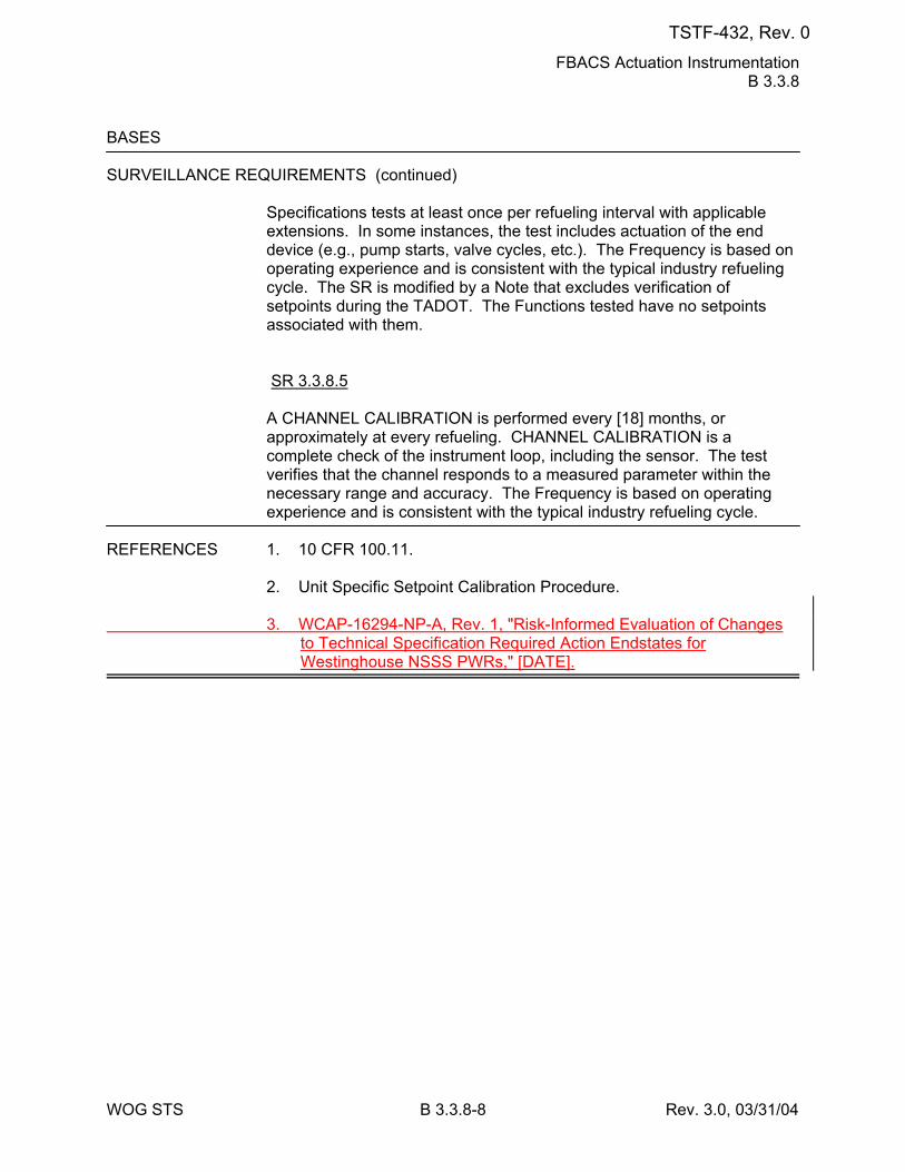
FBACS Actuation Instrumentation B 3.3.8
WOG STS B 3.3.8-8 Rev. 3.0, 03/31/04
BASES SURVEILLANCE REQUIREMENTS (continued)
Specifications tests at least once per refueling interval with applicable extensions. In some instances, the test includes actuation of the end device (e.g., pump starts, valve cycles, etc.). The Frequency is based on operating experience and is consistent with the typical industry refueling cycle. The SR is modified by a Note that excludes verification of setpoints during the TADOT. The Functions tested have no setpoints associated with them. SR 3.3.8.5 A CHANNEL CALIBRATION is performed every [18] months, or approximately at every refueling. CHANNEL CALIBRATION is a complete check of the instrument loop, including the sensor. The test verifies that the channel responds to a measured parameter within the necessary range and accuracy. The Frequency is based on operating experience and is consistent with the typical industry refueling cycle.
REFERENCES 1. 10 CFR 100.11. 2. Unit Specific Setpoint Calibration Procedure. 3. WCAP-16294-NP-A, Rev. 1, "Risk-Informed Evaluation of Changes
to Technical Specification Required Action Endstates for Westinghouse NSSS PWRs," [DATE].
TSTF-432, Rev. 0
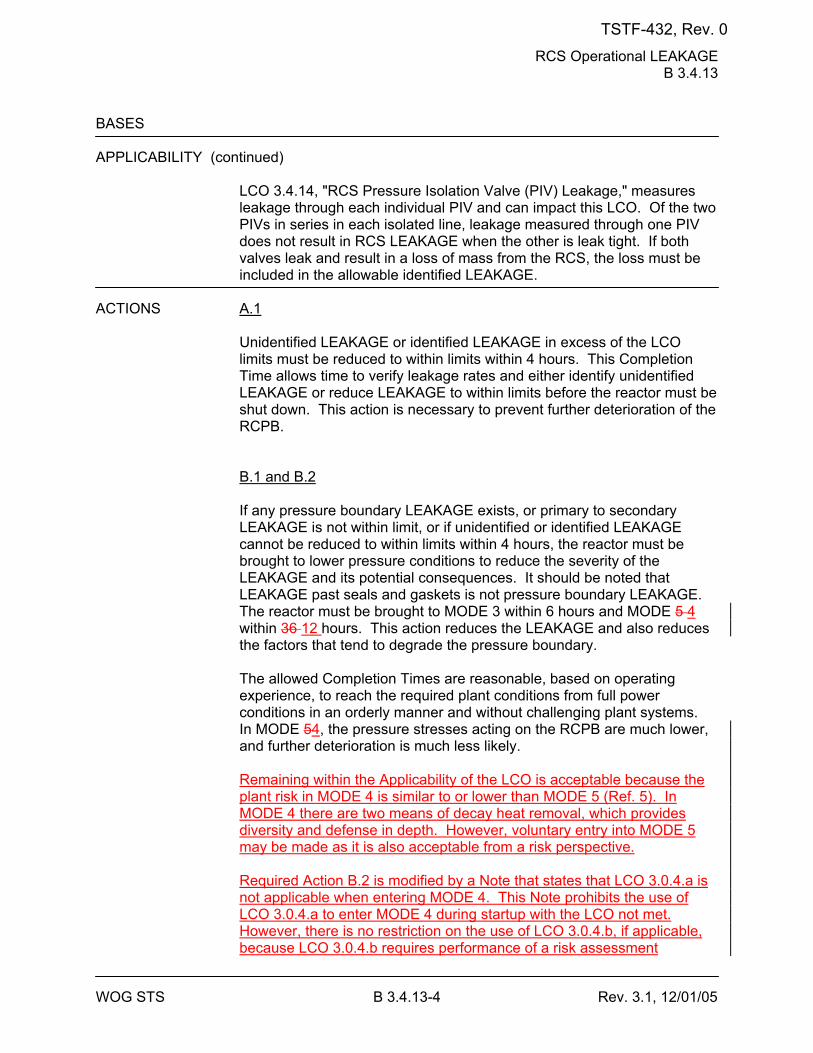
RCS Operational LEAKAGE B 3.4.13
WOG STS B 3.4.13-4 Rev. 3.1, 12/01/05
BASES APPLICABILITY (continued)
LCO 3.4.14, "RCS Pressure Isolation Valve (PIV) Leakage," measures leakage through each individual PIV and can impact this LCO. Of the two PIVs in series in each isolated line, leakage measured through one PIV does not result in RCS LEAKAGE when the other is leak tight. If both valves leak and result in a loss of mass from the RCS, the loss must be included in the allowable identified LEAKAGE.
ACTIONS A.1
Unidentified LEAKAGE or identified LEAKAGE in excess of the LCO limits must be reduced to within limits within 4 hours. This Completion Time allows time to verify leakage rates and either identify unidentified LEAKAGE or reduce LEAKAGE to within limits before the reactor must be shut down. This action is necessary to prevent further deterioration of the RCPB. B.1 and B.2 If any pressure boundary LEAKAGE exists, or primary to secondary LEAKAGE is not within limit, or if unidentified or identified LEAKAGE cannot be reduced to within limits within 4 hours, the reactor must be brought to lower pressure conditions to reduce the severity of the LEAKAGE and its potential consequences. It should be noted that LEAKAGE past seals and gaskets is not pressure boundary LEAKAGE. The reactor must be brought to MODE 3 within 6 hours and MODE 5 4 within 36 12 hours. This action reduces the LEAKAGE and also reduces the factors that tend to degrade the pressure boundary. The allowed Completion Times are reasonable, based on operating experience, to reach the required plant conditions from full power conditions in an orderly manner and without challenging plant systems. In MODE 54, the pressure stresses acting on the RCPB are much lower, and further deterioration is much less likely. Remaining within the Applicability of the LCO is acceptable because the plant risk in MODE 4 is similar to or lower than MODE 5 (Ref. 5). In MODE 4 there are two means of decay heat removal, which provides diversity and defense in depth. However, voluntary entry into MODE 5 may be made as it is also acceptable from a risk perspective. Required Action B.2 is modified by a Note that states that LCO 3.0.4.a is not applicable when entering MODE 4. This Note prohibits the use of LCO 3.0.4.a to enter MODE 4 during startup with the LCO not met. However, there is no restriction on the use of LCO 3.0.4.b, if applicable, because LCO 3.0.4.b requires performance of a risk assessment
TSTF-432, Rev. 0
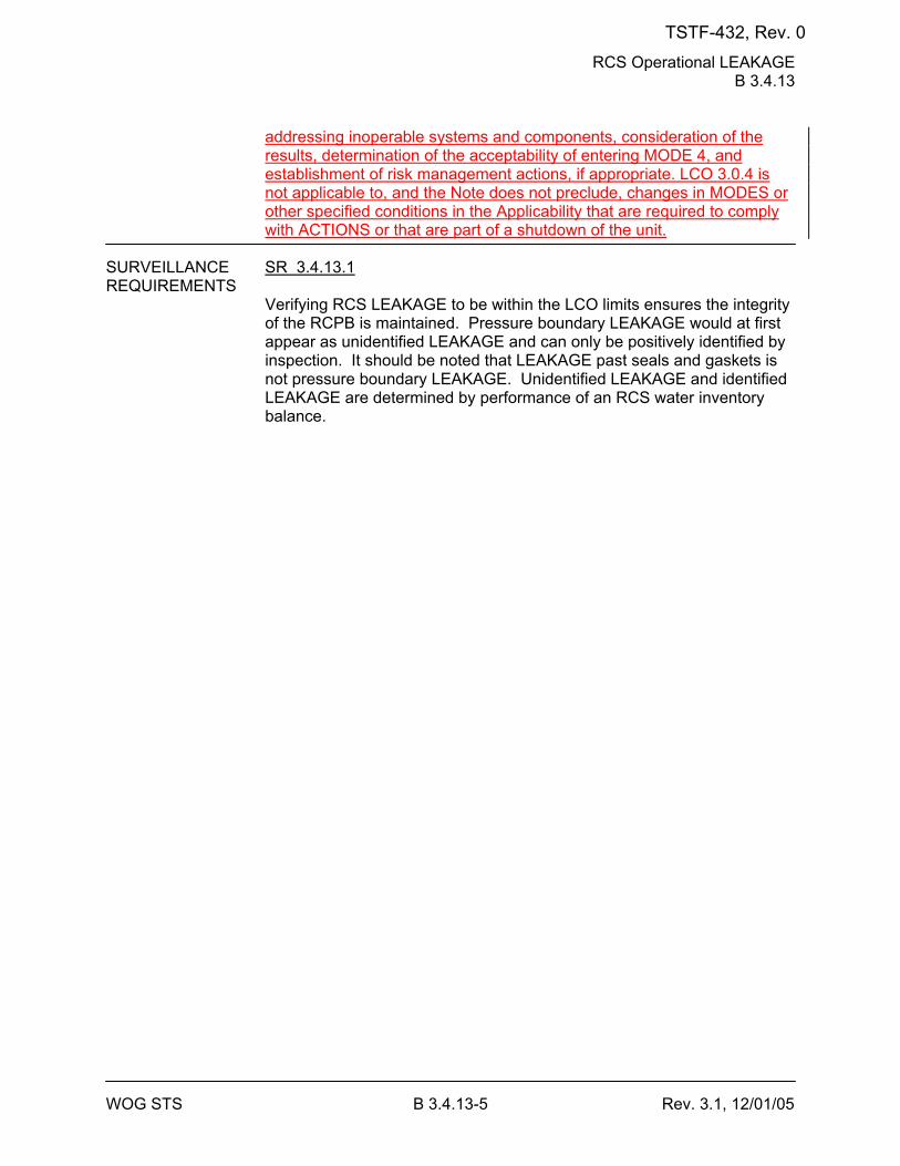
RCS Operational LEAKAGE B 3.4.13
WOG STS B 3.4.13-5 Rev. 3.1, 12/01/05
addressing inoperable systems and components, consideration of the results, determination of the acceptability of entering MODE 4, and establishment of risk management actions, if appropriate. LCO 3.0.4 is not applicable to, and the Note does not preclude, changes in MODES or other specified conditions in the Applicability that are required to comply with ACTIONS or that are part of a shutdown of the unit.
SURVEILLANCE SR 3.4.13.1 REQUIREMENTS
Verifying RCS LEAKAGE to be within the LCO limits ensures the integrity of the RCPB is maintained. Pressure boundary LEAKAGE would at first appear as unidentified LEAKAGE and can only be positively identified by inspection. It should be noted that LEAKAGE past seals and gaskets is not pressure boundary LEAKAGE. Unidentified LEAKAGE and identified LEAKAGE are determined by performance of an RCS water inventory balance.
TSTF-432, Rev. 0
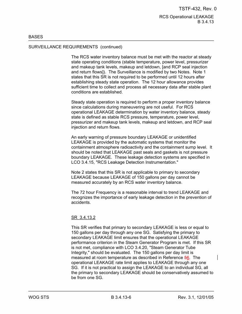
RCS Operational LEAKAGE B 3.4.13
WOG STS B 3.4.13-6 Rev. 3.1, 12/01/05
BASES SURVEILLANCE REQUIREMENTS (continued)
The RCS water inventory balance must be met with the reactor at steady state operating conditions (stable temperature, power level, pressurizer and makeup tank levels, makeup and letdown, [and RCP seal injection and return flows]). The Surveillance is modified by two Notes. Note 1 states that this SR is not required to be performed until 12 hours after establishing steady state operation. The 12 hour allowance provides sufficient time to collect and process all necessary data after stable plant conditions are established. Steady state operation is required to perform a proper inventory balance since calculations during maneuvering are not useful. For RCS operational LEAKAGE determination by water inventory balance, steady state is defined as stable RCS pressure, temperature, power level, pressurizer and makeup tank levels, makeup and letdown, and RCP seal injection and return flows. An early warning of pressure boundary LEAKAGE or unidentified LEAKAGE is provided by the automatic systems that monitor the containment atmosphere radioactivity and the containment sump level. It should be noted that LEAKAGE past seals and gaskets is not pressure boundary LEAKAGE. These leakage detection systems are specified in LCO 3.4.15, "RCS Leakage Detection Instrumentation." Note 2 states that this SR is not applicable to primary to secondary LEAKAGE because LEAKAGE of 150 gallons per day cannot be measured accurately by an RCS water inventory balance. The 72 hour Frequency is a reasonable interval to trend LEAKAGE and recognizes the importance of early leakage detection in the prevention of accidents. SR 3.4.13.2 This SR verifies that primary to secondary LEAKAGE is less or equal to 150 gallons per day through any one SG. Satisfying the primary to secondary LEAKAGE limit ensures that the operational LEAKAGE performance criterion in the Steam Generator Program is met. If this SR is not met, compliance with LCO 3.4.20, "Steam Generator Tube Integrity," should be evaluated. The 150 gallons per day limit is measured at room temperature as described in Reference 56. The operational LEAKAGE rate limit applies to LEAKAGE through any one SG. If it is not practical to assign the LEAKAGE to an individual SG, all the primary to secondary LEAKAGE should be conservatively assumed to be from one SG.
TSTF-432, Rev. 0
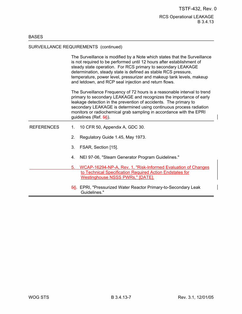
RCS Operational LEAKAGE B 3.4.13
WOG STS B 3.4.13-7 Rev. 3.1, 12/01/05
BASES SURVEILLANCE REQUIREMENTS (continued)
The Surveillance is modified by a Note which states that the Surveillance is not required to be performed until 12 hours after establishment of steady state operation. For RCS primary to secondary LEAKAGE determination, steady state is defined as stable RCS pressure, temperature, power level, pressurizer and makeup tank levels, makeup and letdown, and RCP seal injection and return flows. The Surveillance Frequency of 72 hours is a reasonable interval to trend primary to secondary LEAKAGE and recognizes the importance of early leakage detection in the prevention of accidents. The primary to secondary LEAKAGE is determined using continuous process radiation monitors or radiochemical grab sampling in accordance with the EPRI guidelines (Ref. 56).
REFERENCES 1. 10 CFR 50, Appendix A, GDC 30. 2. Regulatory Guide 1.45, May 1973.
3. FSAR, Section [15]. 4. NEI 97-06, "Steam Generator Program Guidelines." 5. WCAP-16294-NP-A, Rev. 1, "Risk-Informed Evaluation of Changes
to Technical Specification Required Action Endstates for Westinghouse NSSS PWRs," [DATE].
56. EPRI, "Pressurized Water Reactor Primary-to-Secondary Leak
Guidelines."
TSTF-432, Rev. 0
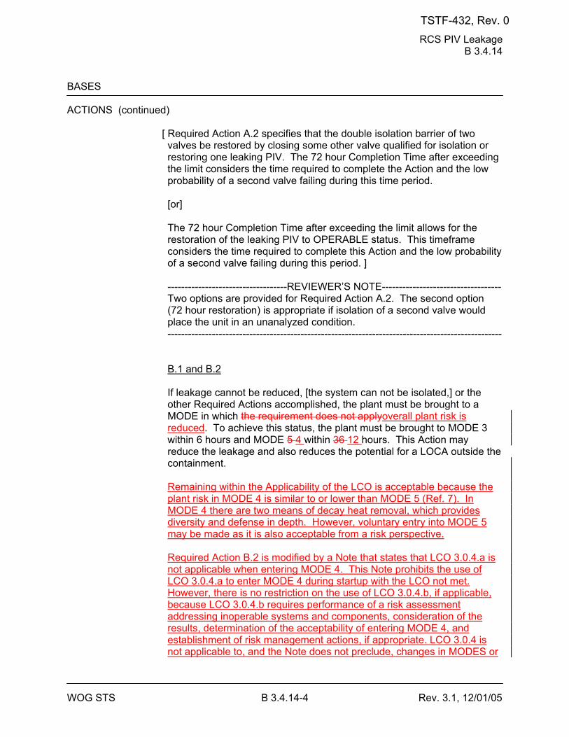
RCS PIV Leakage B 3.4.14
WOG STS B 3.4.14-4 Rev. 3.1, 12/01/05
BASES ACTIONS (continued)
[ Required Action A.2 specifies that the double isolation barrier of two valves be restored by closing some other valve qualified for isolation or restoring one leaking PIV. The 72 hour Completion Time after exceeding the limit considers the time required to complete the Action and the low probability of a second valve failing during this time period. [or] The 72 hour Completion Time after exceeding the limit allows for the restoration of the leaking PIV to OPERABLE status. This timeframe considers the time required to complete this Action and the low probability of a second valve failing during this period. ] -----------------------------------REVIEWER’S NOTE----------------------------------- Two options are provided for Required Action A.2. The second option (72 hour restoration) is appropriate if isolation of a second valve would place the unit in an unanalyzed condition. -------------------------------------------------------------------------------------------------- B.1 and B.2 If leakage cannot be reduced, [the system can not be isolated,] or the other Required Actions accomplished, the plant must be brought to a MODE in which the requirement does not applyoverall plant risk is reduced. To achieve this status, the plant must be brought to MODE 3 within 6 hours and MODE 5 4 within 36 12 hours. This Action may reduce the leakage and also reduces the potential for a LOCA outside the containment. Remaining within the Applicability of the LCO is acceptable because the plant risk in MODE 4 is similar to or lower than MODE 5 (Ref. 7). In MODE 4 there are two means of decay heat removal, which provides diversity and defense in depth. However, voluntary entry into MODE 5 may be made as it is also acceptable from a risk perspective. Required Action B.2 is modified by a Note that states that LCO 3.0.4.a is not applicable when entering MODE 4. This Note prohibits the use of LCO 3.0.4.a to enter MODE 4 during startup with the LCO not met. However, there is no restriction on the use of LCO 3.0.4.b, if applicable, because LCO 3.0.4.b requires performance of a risk assessment addressing inoperable systems and components, consideration of the results, determination of the acceptability of entering MODE 4, and establishment of risk management actions, if appropriate. LCO 3.0.4 is not applicable to, and the Note does not preclude, changes in MODES or
TSTF-432, Rev. 0
RCS PIV Leakage B 3.4.14
WOG STS B 3.4.14-5 Rev. 3.1, 12/01/05
other specified conditions in the Applicability that are required to comply with ACTIONS or that are part of a shutdown of the unit. The allowed Completion Times are reasonable based on operating experience, to reach the required plant conditions from full power conditions in an orderly manner and without challenging plant systems. C.1 The inoperability of the RHR autoclosure interlock renders the RHR suction isolation valves incapable of isolating in response to a high pressure condition and preventing inadvertent opening of the valves at RCS pressures in excess of the RHR systems design pressure. If the RHR autoclosure interlock is inoperable, operation may continue as long as the affected RHR suction penetration is closed by at least one closed manual or deactivated automatic valve within 4 hours. This Action accomplishes the purpose of the autoclosure function.
TSTF-432, Rev. 0
RCS PIV Leakage B 3.4.14
WOG STS B 3.4.14-6 Rev. 3.1, 12/01/05
BASES SURVEILLANCE SR 3.4.14.1 REQUIREMENTS
Performance of leakage testing on each RCS PIV or isolation valve used to satisfy Required Action A.1 and Required Action A.2 is required to verify that leakage is below the specified limit and to identify each leaking valve. The leakage limit of 0.5 gpm per inch of nominal valve diameter up to 5 gpm maximum applies to each valve. Leakage testing requires a stable pressure condition. For the two PIVs in series, the leakage requirement applies to each valve individually and not to the combined leakage across both valves. If the PIVs are not individually leakage tested, one valve may have failed completely and not be detected if the other valve in series meets the leakage requirement. In this situation, the protection provided by redundant valves would be lost. Testing is to be performed every [18] months, a typical refueling cycle, if the plant does not go into MODE 5 for at least 7 days. The [18 month] Frequency is consistent with 10 CFR 50.55a(g) (Ref. 89) as contained in the Inservice Testing Program, is within frequency allowed by the American Society of Mechanical Engineers (ASME) Code (Ref. 78), and is based on the need to perform such surveillances under the conditions that apply during an outage and the potential for an unplanned transient if the Surveillance were performed with the reactor at power. In addition, testing must be performed once after the valve has been opened by flow or exercised to ensure tight reseating. PIVs disturbed in the performance of this Surveillance should also be tested unless documentation shows that an infinite testing loop cannot practically be avoided. Testing must be performed within 24 hours after the valve has been reseated. Within 24 hours is a reasonable and practical time limit for performing this test after opening or reseating a valve. The leakage limit is to be met at the RCS pressure associated with MODES 1 and 2. This permits leakage testing at high differential pressures with stable conditions not possible in the MODES with lower pressures. Entry into MODES 3 and 4 is allowed to establish the necessary differential pressures and stable conditions to allow for performance of this Surveillance. The Note that allows this provision is complementary to the Frequency of prior to entry into MODE 2 whenever the unit has been in MODE 5 for 7 days or more, if leakage testing has not been performed in the previous 9 months. In addition, this Surveillance is not required to
TSTF-432, Rev. 0
RCS PIV Leakage B 3.4.14
WOG STS B 3.4.14-7 Rev. 3.1, 12/01/05
BASES SURVEILLANCE REQUIREMENTS (continued)
be performed on the RHR System when the RHR System is aligned to the RCS in the shutdown cooling mode of operation. PIVs contained in the RHR shutdown cooling flow path must be leakage rate tested after RHR is secured and stable unit conditions and the necessary differential pressures are established.
[ SR 3.4.14.2 and SR 3.4.14.3 Verifying that the RHR autoclosure interlocks are OPERABLE ensures that RCS pressure will not pressurize the RHR system beyond 125% of its design pressure of [600] psig. The interlock setpoint that prevents the valves from being opened is set so the actual RCS pressure must be < [425] psig to open the valves. This setpoint ensures the RHR design pressure will not be exceeded and the RHR relief valves will not lift. The [18] month Frequency is based on the need to perform the Surveillance under conditions that apply during a plant outage. The [18] month Frequency is also acceptable based on consideration of the design reliability (and confirming operating experience) of the equipment. These SRs are modified by Notes allowing the RHR autoclosure function to be disabled when using the RHR System suction relief valves for cold overpressure protection in accordance with SR 3.4.12.7. ]
REFERENCES 1. 10 CFR 50.2. 2. 10 CFR 50.55a(c). 3. 10 CFR 50, Appendix A, Section V, GDC 55. 4. WASH-1400 (NUREG-75/014), Appendix V, October 1975. 5. NUREG-0677, May 1980.
[ 6. Document containing list of PIVs. ]
7. WCAP-16294-NP-A, Rev. 1, "Risk-Informed Evaluation of Changes
to Technical Specification Required Action Endstates for Westinghouse NSSS PWRs," [DATE].
78. ASME Code for Operation and Maintenance of Nuclear Power
Plants.
89. 10 CFR 50.55a(g).
TSTF-432, Rev. 0
RCS Leakage Detection Instrumentation B 3.4.15
WOG STS B 3.4.15-5 Rev. 3.0, 03/31/04
BASES ACTIONS (continued)
[ D.1 and D.2 With the required containment atmosphere radioactivity monitor and the required containment air cooler condensate flow rate monitor inoperable, the only means of detecting leakage is the containment sump monitor. This Condition does not provide the required diverse means of leakage detection. The Required Action is to restore either of the inoperable required monitors to OPERABLE status within 30 days to regain the intended leakage detection diversity. The 30 day Completion Time ensures that the plant will not be operated in a reduced configuration for a lengthy time period. ] E.1 and E.2 If a Required Action of Condition A, B, [C], or [D] cannot be met, the plant must be brought to a MODE in which the requirement does not applyoverall plant risk is reduced. To achieve this status, the plant must be brought to at least MODE 3 within 6 hours and to MODE 5 4 within 36 12 hours. Remaining within the Applicability of the LCO is acceptable because the plant risk in MODE 4 is similar to or lower than MODE 5 (Ref. 4). In MODE 4 there are two means of decay heat removal, which provides diversity and defense in depth. However, voluntary entry into MODE 5 may be made as it is also acceptable from a risk perspective. Required Action E.2 is modified by a Note that states that LCO 3.0.4.a is not applicable when entering MODE 4. This Note prohibits the use of LCO 3.0.4.a to enter MODE 4 during startup with the LCO not met. However, there is no restriction on the use of LCO 3.0.4.b, if applicable, because LCO 3.0.4.b requires performance of a risk assessment addressing inoperable systems and components, consideration of the results, determination of the acceptability of entering MODE 4, and establishment of risk management actions, if appropriate. LCO 3.0.4 is not applicable to, and the Note does not preclude, changes in MODES or other specified conditions in the Applicability that are required to comply with ACTIONS or that are part of a shutdown of the unit. The allowed Completion Times are reasonable, based on operating experience, to reach the required plant conditions from full power conditions in an orderly manner and without challenging plant systems.
TSTF-432, Rev. 0
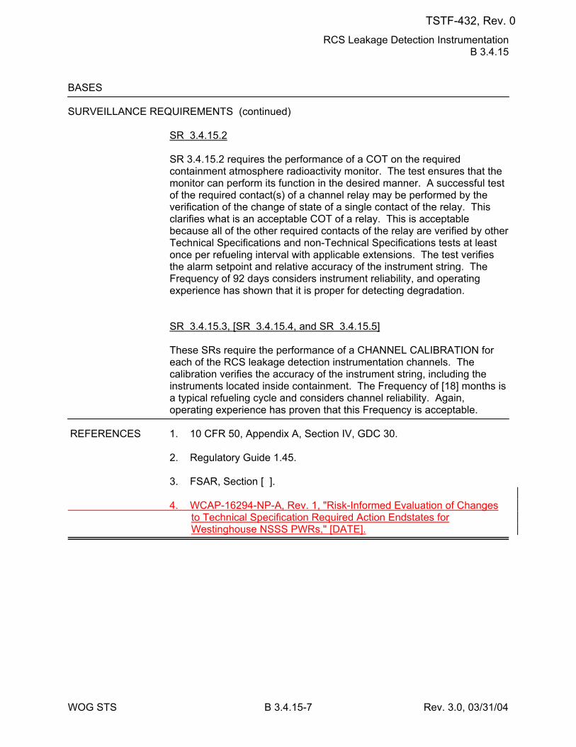
RCS Leakage Detection Instrumentation B 3.4.15
WOG STS B 3.4.15-7 Rev. 3.0, 03/31/04
BASES SURVEILLANCE REQUIREMENTS (continued)
SR 3.4.15.2 SR 3.4.15.2 requires the performance of a COT on the required containment atmosphere radioactivity monitor. The test ensures that the monitor can perform its function in the desired manner. A successful test of the required contact(s) of a channel relay may be performed by the verification of the change of state of a single contact of the relay. This clarifies what is an acceptable COT of a relay. This is acceptable because all of the other required contacts of the relay are verified by other Technical Specifications and non-Technical Specifications tests at least once per refueling interval with applicable extensions. The test verifies the alarm setpoint and relative accuracy of the instrument string. The Frequency of 92 days considers instrument reliability, and operating experience has shown that it is proper for detecting degradation. SR 3.4.15.3, [SR 3.4.15.4, and SR 3.4.15.5] These SRs require the performance of a CHANNEL CALIBRATION for each of the RCS leakage detection instrumentation channels. The calibration verifies the accuracy of the instrument string, including the instruments located inside containment. The Frequency of [18] months is a typical refueling cycle and considers channel reliability. Again, operating experience has proven that this Frequency is acceptable.
REFERENCES 1. 10 CFR 50, Appendix A, Section IV, GDC 30. 2. Regulatory Guide 1.45. 3. FSAR, Section [ ]. 4. WCAP-16294-NP-A, Rev. 1, "Risk-Informed Evaluation of Changes
to Technical Specification Required Action Endstates for Westinghouse NSSS PWRs," [DATE].
TSTF-432, Rev. 0
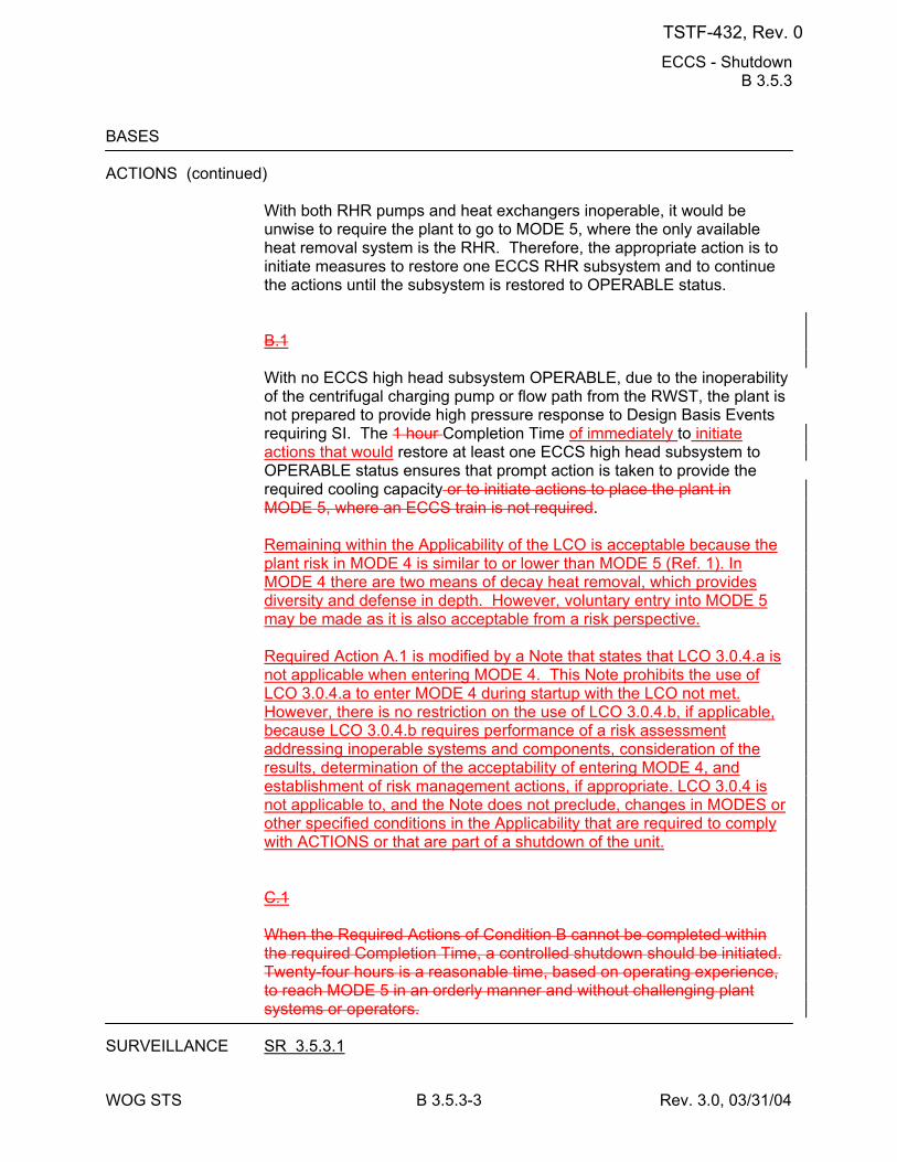
ECCS - Shutdown B 3.5.3
WOG STS B 3.5.3-3 Rev. 3.0, 03/31/04
BASES ACTIONS (continued)
With both RHR pumps and heat exchangers inoperable, it would be unwise to require the plant to go to MODE 5, where the only available heat removal system is the RHR. Therefore, the appropriate action is to initiate measures to restore one ECCS RHR subsystem and to continue the actions until the subsystem is restored to OPERABLE status. B.1 With no ECCS high head subsystem OPERABLE, due to the inoperability of the centrifugal charging pump or flow path from the RWST, the plant is not prepared to provide high pressure response to Design Basis Events requiring SI. The 1 hour Completion Time of immediately to initiate actions that would restore at least one ECCS high head subsystem to OPERABLE status ensures that prompt action is taken to provide the required cooling capacity or to initiate actions to place the plant in MODE 5, where an ECCS train is not required. Remaining within the Applicability of the LCO is acceptable because the plant risk in MODE 4 is similar to or lower than MODE 5 (Ref. 1). In MODE 4 there are two means of decay heat removal, which provides diversity and defense in depth. However, voluntary entry into MODE 5 may be made as it is also acceptable from a risk perspective. Required Action A.1 is modified by a Note that states that LCO 3.0.4.a is not applicable when entering MODE 4. This Note prohibits the use of LCO 3.0.4.a to enter MODE 4 during startup with the LCO not met. However, there is no restriction on the use of LCO 3.0.4.b, if applicable, because LCO 3.0.4.b requires performance of a risk assessment addressing inoperable systems and components, consideration of the results, determination of the acceptability of entering MODE 4, and establishment of risk management actions, if appropriate. LCO 3.0.4 is not applicable to, and the Note does not preclude, changes in MODES or other specified conditions in the Applicability that are required to comply with ACTIONS or that are part of a shutdown of the unit. C.1 When the Required Actions of Condition B cannot be completed within the required Completion Time, a controlled shutdown should be initiated. Twenty-four hours is a reasonable time, based on operating experience, to reach MODE 5 in an orderly manner and without challenging plant systems or operators.
SURVEILLANCE SR 3.5.3.1
TSTF-432, Rev. 0
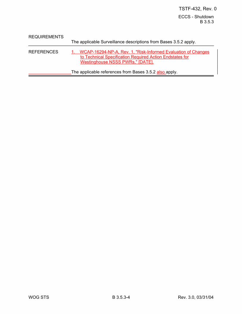
ECCS - Shutdown B 3.5.3
WOG STS B 3.5.3-4 Rev. 3.0, 03/31/04
REQUIREMENTS The applicable Surveillance descriptions from Bases 3.5.2 apply.
REFERENCES 1. WCAP-16294-NP-A, Rev. 1, "Risk-Informed Evaluation of Changes
to Technical Specification Required Action Endstates for Westinghouse NSSS PWRs," [DATE].
The applicable references from Bases 3.5.2 also apply.
TSTF-432, Rev. 0
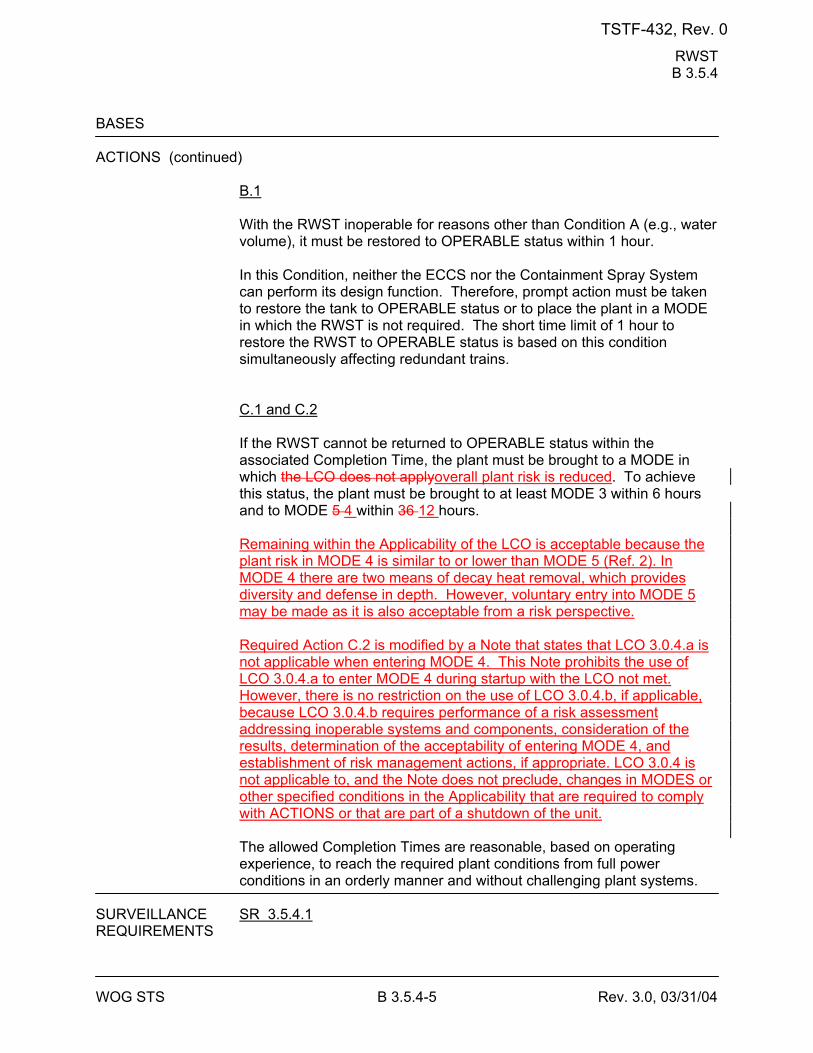
RWST B 3.5.4
WOG STS B 3.5.4-5 Rev. 3.0, 03/31/04
BASES ACTIONS (continued)
B.1 With the RWST inoperable for reasons other than Condition A (e.g., water volume), it must be restored to OPERABLE status within 1 hour. In this Condition, neither the ECCS nor the Containment Spray System can perform its design function. Therefore, prompt action must be taken to restore the tank to OPERABLE status or to place the plant in a MODE in which the RWST is not required. The short time limit of 1 hour to restore the RWST to OPERABLE status is based on this condition simultaneously affecting redundant trains. C.1 and C.2 If the RWST cannot be returned to OPERABLE status within the associated Completion Time, the plant must be brought to a MODE in which the LCO does not applyoverall plant risk is reduced. To achieve this status, the plant must be brought to at least MODE 3 within 6 hours and to MODE 5 4 within 36 12 hours. Remaining within the Applicability of the LCO is acceptable because the plant risk in MODE 4 is similar to or lower than MODE 5 (Ref. 2). In MODE 4 there are two means of decay heat removal, which provides diversity and defense in depth. However, voluntary entry into MODE 5 may be made as it is also acceptable from a risk perspective. Required Action C.2 is modified by a Note that states that LCO 3.0.4.a is not applicable when entering MODE 4. This Note prohibits the use of LCO 3.0.4.a to enter MODE 4 during startup with the LCO not met. However, there is no restriction on the use of LCO 3.0.4.b, if applicable, because LCO 3.0.4.b requires performance of a risk assessment addressing inoperable systems and components, consideration of the results, determination of the acceptability of entering MODE 4, and establishment of risk management actions, if appropriate. LCO 3.0.4 is not applicable to, and the Note does not preclude, changes in MODES or other specified conditions in the Applicability that are required to comply with ACTIONS or that are part of a shutdown of the unit. The allowed Completion Times are reasonable, based on operating experience, to reach the required plant conditions from full power conditions in an orderly manner and without challenging plant systems.
SURVEILLANCE SR 3.5.4.1 REQUIREMENTS
TSTF-432, Rev. 0
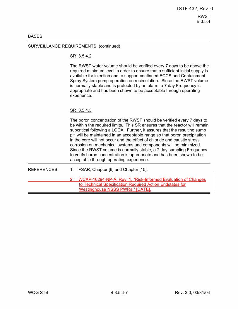
RWST B 3.5.4
WOG STS B 3.5.4-7 Rev. 3.0, 03/31/04
BASES SURVEILLANCE REQUIREMENTS (continued)
SR 3.5.4.2 The RWST water volume should be verified every 7 days to be above the required minimum level in order to ensure that a sufficient initial supply is available for injection and to support continued ECCS and Containment Spray System pump operation on recirculation. Since the RWST volume is normally stable and is protected by an alarm, a 7 day Frequency is appropriate and has been shown to be acceptable through operating experience. SR 3.5.4.3 The boron concentration of the RWST should be verified every 7 days to be within the required limits. This SR ensures that the reactor will remain subcritical following a LOCA. Further, it assures that the resulting sump pH will be maintained in an acceptable range so that boron precipitation in the core will not occur and the effect of chloride and caustic stress corrosion on mechanical systems and components will be minimized. Since the RWST volume is normally stable, a 7 day sampling Frequency to verify boron concentration is appropriate and has been shown to be acceptable through operating experience.
REFERENCES 1. FSAR, Chapter [6] and Chapter [15]. 2. WCAP-16294-NP-A, Rev. 1, "Risk-Informed Evaluation of Changes
to Technical Specification Required Action Endstates for Westinghouse NSSS PWRs," [DATE].
TSTF-432, Rev. 0
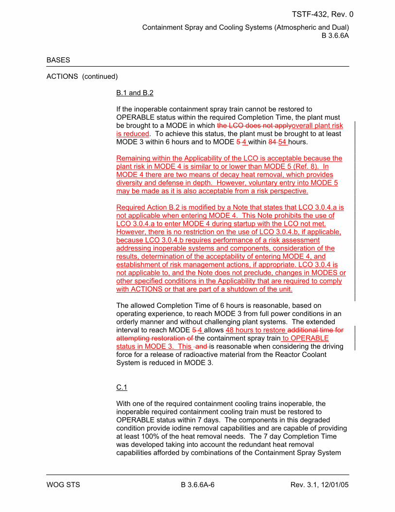
Containment Spray and Cooling Systems (Atmospheric and Dual) B 3.6.6A
WOG STS B 3.6.6A-6 Rev. 3.1, 12/01/05
BASES ACTIONS (continued)
B.1 and B.2 If the inoperable containment spray train cannot be restored to OPERABLE status within the required Completion Time, the plant must be brought to a MODE in which the LCO does not applyoverall plant risk is reduced. To achieve this status, the plant must be brought to at least MODE 3 within 6 hours and to MODE 5 4 within 84 54 hours. Remaining within the Applicability of the LCO is acceptable because the plant risk in MODE 4 is similar to or lower than MODE 5 (Ref. 8). In MODE 4 there are two means of decay heat removal, which provides diversity and defense in depth. However, voluntary entry into MODE 5 may be made as it is also acceptable from a risk perspective. Required Action B.2 is modified by a Note that states that LCO 3.0.4.a is not applicable when entering MODE 4. This Note prohibits the use of LCO 3.0.4.a to enter MODE 4 during startup with the LCO not met. However, there is no restriction on the use of LCO 3.0.4.b, if applicable, because LCO 3.0.4.b requires performance of a risk assessment addressing inoperable systems and components, consideration of the results, determination of the acceptability of entering MODE 4, and establishment of risk management actions, if appropriate. LCO 3.0.4 is not applicable to, and the Note does not preclude, changes in MODES or other specified conditions in the Applicability that are required to comply with ACTIONS or that are part of a shutdown of the unit. The allowed Completion Time of 6 hours is reasonable, based on operating experience, to reach MODE 3 from full power conditions in an orderly manner and without challenging plant systems. The extended interval to reach MODE 5 4 allows 48 hours to restore additional time for attempting restoration of the containment spray train to OPERABLE status in MODE 3. This and is reasonable when considering the driving force for a release of radioactive material from the Reactor Coolant System is reduced in MODE 3. C.1 With one of the required containment cooling trains inoperable, the inoperable required containment cooling train must be restored to OPERABLE status within 7 days. The components in this degraded condition provide iodine removal capabilities and are capable of providing at least 100% of the heat removal needs. The 7 day Completion Time was developed taking into account the redundant heat removal capabilities afforded by combinations of the Containment Spray System
TSTF-432, Rev. 0
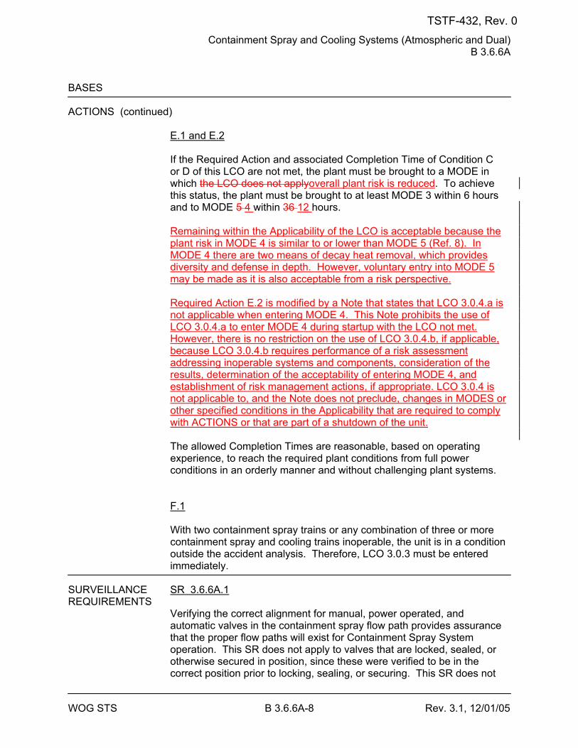
Containment Spray and Cooling Systems (Atmospheric and Dual) B 3.6.6A
WOG STS B 3.6.6A-8 Rev. 3.1, 12/01/05
BASES ACTIONS (continued)
E.1 and E.2 If the Required Action and associated Completion Time of Condition C or D of this LCO are not met, the plant must be brought to a MODE in which the LCO does not applyoverall plant risk is reduced. To achieve this status, the plant must be brought to at least MODE 3 within 6 hours and to MODE 5 4 within 36 12 hours. Remaining within the Applicability of the LCO is acceptable because the plant risk in MODE 4 is similar to or lower than MODE 5 (Ref. 8). In MODE 4 there are two means of decay heat removal, which provides diversity and defense in depth. However, voluntary entry into MODE 5 may be made as it is also acceptable from a risk perspective. Required Action E.2 is modified by a Note that states that LCO 3.0.4.a is not applicable when entering MODE 4. This Note prohibits the use of LCO 3.0.4.a to enter MODE 4 during startup with the LCO not met. However, there is no restriction on the use of LCO 3.0.4.b, if applicable, because LCO 3.0.4.b requires performance of a risk assessment addressing inoperable systems and components, consideration of the results, determination of the acceptability of entering MODE 4, and establishment of risk management actions, if appropriate. LCO 3.0.4 is not applicable to, and the Note does not preclude, changes in MODES or other specified conditions in the Applicability that are required to comply with ACTIONS or that are part of a shutdown of the unit. The allowed Completion Times are reasonable, based on operating experience, to reach the required plant conditions from full power conditions in an orderly manner and without challenging plant systems. F.1 With two containment spray trains or any combination of three or more containment spray and cooling trains inoperable, the unit is in a condition outside the accident analysis. Therefore, LCO 3.0.3 must be entered immediately.
SURVEILLANCE SR 3.6.6A.1 REQUIREMENTS
Verifying the correct alignment for manual, power operated, and automatic valves in the containment spray flow path provides assurance that the proper flow paths will exist for Containment Spray System operation. This SR does not apply to valves that are locked, sealed, or otherwise secured in position, since these were verified to be in the correct position prior to locking, sealing, or securing. This SR does not
TSTF-432, Rev. 0
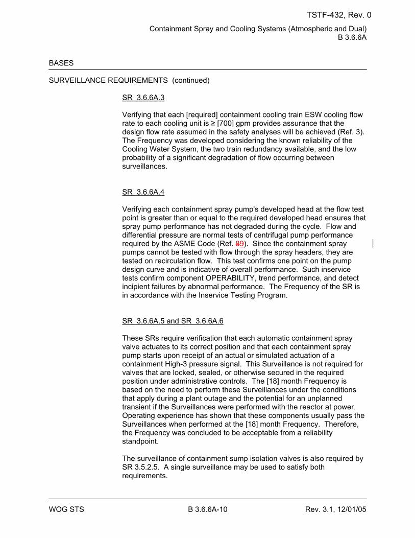
Containment Spray and Cooling Systems (Atmospheric and Dual) B 3.6.6A
WOG STS B 3.6.6A-10 Rev. 3.1, 12/01/05
BASES SURVEILLANCE REQUIREMENTS (continued)
SR 3.6.6A.3 Verifying that each [required] containment cooling train ESW cooling flow rate to each cooling unit is ≥ [700] gpm provides assurance that the design flow rate assumed in the safety analyses will be achieved (Ref. 3). The Frequency was developed considering the known reliability of the Cooling Water System, the two train redundancy available, and the low probability of a significant degradation of flow occurring between surveillances. SR 3.6.6A.4 Verifying each containment spray pump's developed head at the flow test point is greater than or equal to the required developed head ensures that spray pump performance has not degraded during the cycle. Flow and differential pressure are normal tests of centrifugal pump performance required by the ASME Code (Ref. 89). Since the containment spray pumps cannot be tested with flow through the spray headers, they are tested on recirculation flow. This test confirms one point on the pump design curve and is indicative of overall performance. Such inservice tests confirm component OPERABILITY, trend performance, and detect incipient failures by abnormal performance. The Frequency of the SR is in accordance with the Inservice Testing Program. SR 3.6.6A.5 and SR 3.6.6A.6 These SRs require verification that each automatic containment spray valve actuates to its correct position and that each containment spray pump starts upon receipt of an actual or simulated actuation of a containment High-3 pressure signal. This Surveillance is not required for valves that are locked, sealed, or otherwise secured in the required position under administrative controls. The [18] month Frequency is based on the need to perform these Surveillances under the conditions that apply during a plant outage and the potential for an unplanned transient if the Surveillances were performed with the reactor at power. Operating experience has shown that these components usually pass the Surveillances when performed at the [18] month Frequency. Therefore, the Frequency was concluded to be acceptable from a reliability standpoint. The surveillance of containment sump isolation valves is also required by SR 3.5.2.5. A single surveillance may be used to satisfy both requirements.
TSTF-432, Rev. 0
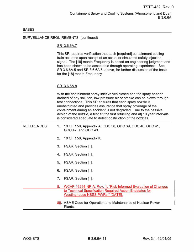
Containment Spray and Cooling Systems (Atmospheric and Dual) B 3.6.6A
WOG STS B 3.6.6A-11 Rev. 3.1, 12/01/05
BASES SURVEILLANCE REQUIREMENTS (continued)
SR 3.6.6A.7 This SR requires verification that each [required] containment cooling train actuates upon receipt of an actual or simulated safety injection signal. The [18] month Frequency is based on engineering judgment and has been shown to be acceptable through operating experience. See SR 3.6.6A.5 and SR 3.6.6A.6, above, for further discussion of the basis for the [18] month Frequency. SR 3.6.6A.8 With the containment spray inlet valves closed and the spray header drained of any solution, low pressure air or smoke can be blown through test connections. This SR ensures that each spray nozzle is unobstructed and provides assurance that spray coverage of the containment during an accident is not degraded. Due to the passive design of the nozzle, a test at [the first refueling and at] 10 year intervals is considered adequate to detect obstruction of the nozzles.
REFERENCES 1. 10 CFR 50, Appendix A, GDC 38, GDC 39, GDC 40, GDC 41,
GDC 42, and GDC 43. 2. 10 CFR 50, Appendix K. 3. FSAR, Section [ ]. 4. FSAR, Section [ ]. 5. FSAR, Section [ ]. 6. FSAR, Section [ ]. 7. FSAR, Section [ ]. 8. WCAP-16294-NP-A, Rev. 1, "Risk-Informed Evaluation of Changes
to Technical Specification Required Action Endstates for Westinghouse NSSS PWRs," [DATE].
89. ASME Code for Operation and Maintenance of Nuclear Power
Plants.
TSTF-432, Rev. 0
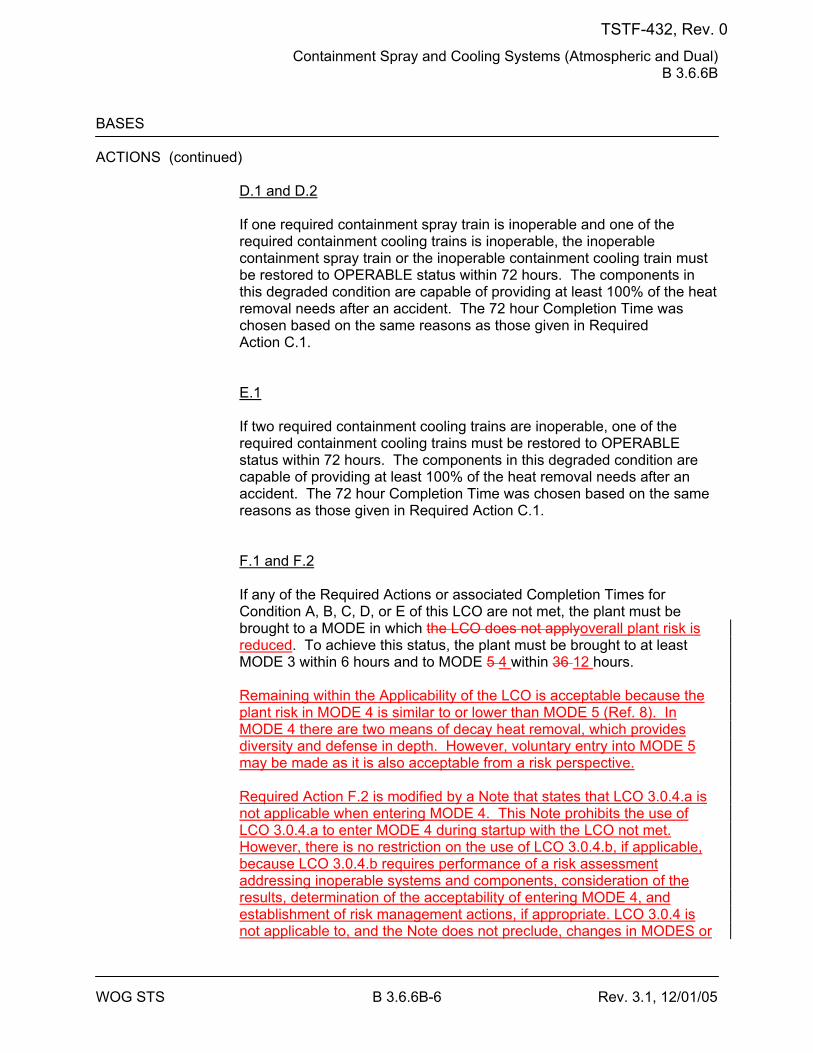
Containment Spray and Cooling Systems (Atmospheric and Dual) B 3.6.6B
WOG STS B 3.6.6B-6 Rev. 3.1, 12/01/05
BASES ACTIONS (continued)
D.1 and D.2 If one required containment spray train is inoperable and one of the required containment cooling trains is inoperable, the inoperable containment spray train or the inoperable containment cooling train must be restored to OPERABLE status within 72 hours. The components in this degraded condition are capable of providing at least 100% of the heat removal needs after an accident. The 72 hour Completion Time was chosen based on the same reasons as those given in Required Action C.1. E.1 If two required containment cooling trains are inoperable, one of the required containment cooling trains must be restored to OPERABLE status within 72 hours. The components in this degraded condition are capable of providing at least 100% of the heat removal needs after an accident. The 72 hour Completion Time was chosen based on the same reasons as those given in Required Action C.1. F.1 and F.2 If any of the Required Actions or associated Completion Times for Condition A, B, C, D, or E of this LCO are not met, the plant must be brought to a MODE in which the LCO does not applyoverall plant risk is reduced. To achieve this status, the plant must be brought to at least MODE 3 within 6 hours and to MODE 5 4 within 36 12 hours. Remaining within the Applicability of the LCO is acceptable because the plant risk in MODE 4 is similar to or lower than MODE 5 (Ref. 8). In MODE 4 there are two means of decay heat removal, which provides diversity and defense in depth. However, voluntary entry into MODE 5 may be made as it is also acceptable from a risk perspective. Required Action F.2 is modified by a Note that states that LCO 3.0.4.a is not applicable when entering MODE 4. This Note prohibits the use of LCO 3.0.4.a to enter MODE 4 during startup with the LCO not met. However, there is no restriction on the use of LCO 3.0.4.b, if applicable, because LCO 3.0.4.b requires performance of a risk assessment addressing inoperable systems and components, consideration of the results, determination of the acceptability of entering MODE 4, and establishment of risk management actions, if appropriate. LCO 3.0.4 is not applicable to, and the Note does not preclude, changes in MODES or
TSTF-432, Rev. 0
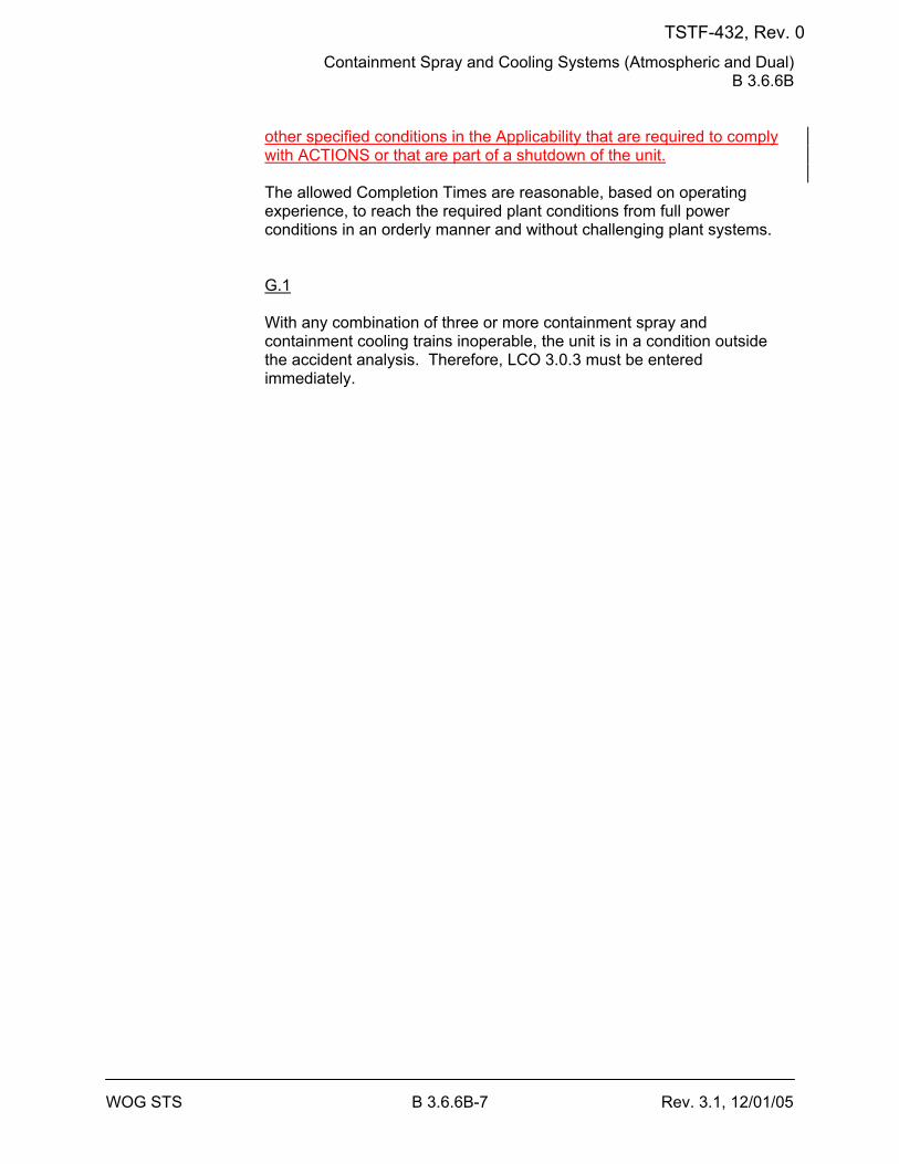
Containment Spray and Cooling Systems (Atmospheric and Dual) B 3.6.6B
WOG STS B 3.6.6B-7 Rev. 3.1, 12/01/05
other specified conditions in the Applicability that are required to comply with ACTIONS or that are part of a shutdown of the unit. The allowed Completion Times are reasonable, based on operating experience, to reach the required plant conditions from full power conditions in an orderly manner and without challenging plant systems. G.1 With any combination of three or more containment spray and containment cooling trains inoperable, the unit is in a condition outside the accident analysis. Therefore, LCO 3.0.3 must be entered immediately.
TSTF-432, Rev. 0
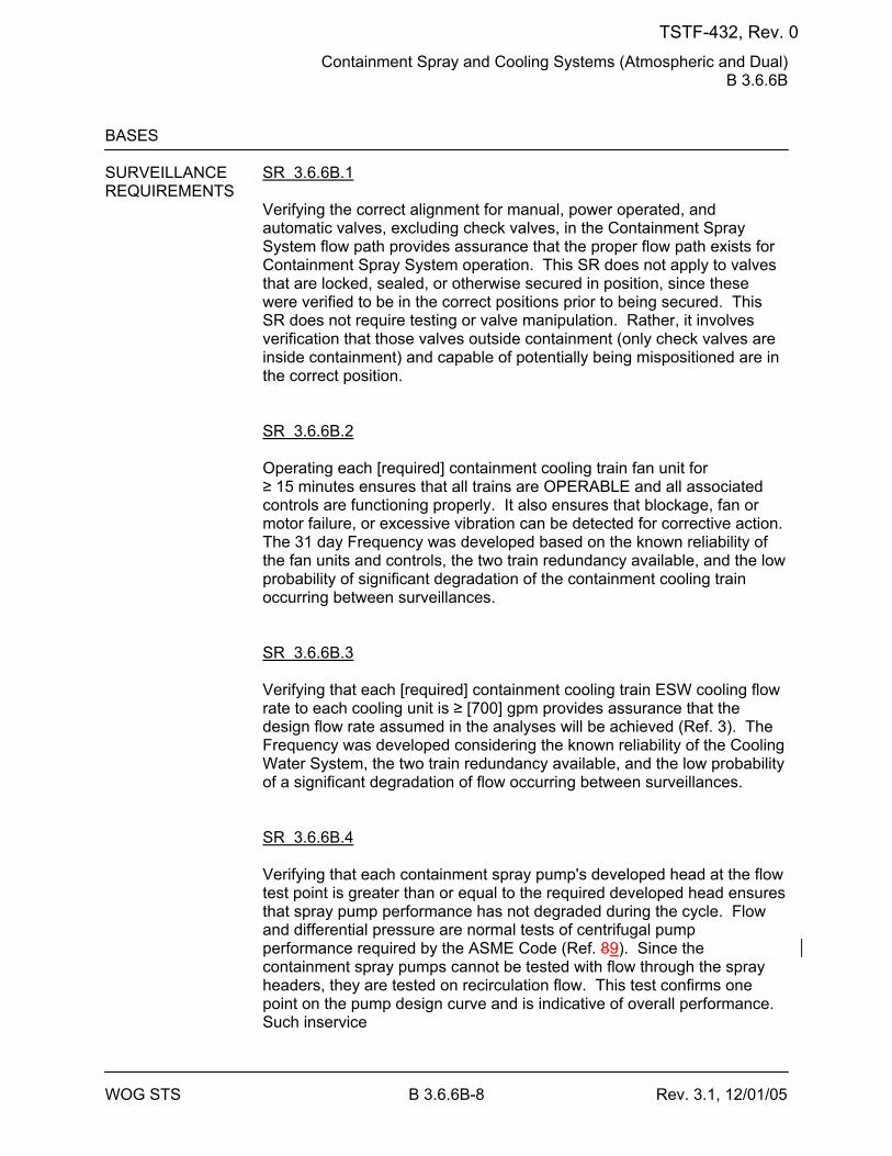
Containment Spray and Cooling Systems (Atmospheric and Dual) B 3.6.6B
WOG STS B 3.6.6B-8 Rev. 3.1, 12/01/05
BASES SURVEILLANCE SR 3.6.6B.1 REQUIREMENTS
Verifying the correct alignment for manual, power operated, and automatic valves, excluding check valves, in the Containment Spray System flow path provides assurance that the proper flow path exists for Containment Spray System operation. This SR does not apply to valves that are locked, sealed, or otherwise secured in position, since these were verified to be in the correct positions prior to being secured. This SR does not require testing or valve manipulation. Rather, it involves verification that those valves outside containment (only check valves are inside containment) and capable of potentially being mispositioned are in the correct position. SR 3.6.6B.2 Operating each [required] containment cooling train fan unit for ≥ 15 minutes ensures that all trains are OPERABLE and all associated controls are functioning properly. It also ensures that blockage, fan or motor failure, or excessive vibration can be detected for corrective action. The 31 day Frequency was developed based on the known reliability of the fan units and controls, the two train redundancy available, and the low probability of significant degradation of the containment cooling train occurring between surveillances. SR 3.6.6B.3 Verifying that each [required] containment cooling train ESW cooling flow rate to each cooling unit is ≥ [700] gpm provides assurance that the design flow rate assumed in the analyses will be achieved (Ref. 3). The Frequency was developed considering the known reliability of the Cooling Water System, the two train redundancy available, and the low probability of a significant degradation of flow occurring between surveillances. SR 3.6.6B.4 Verifying that each containment spray pump's developed head at the flow test point is greater than or equal to the required developed head ensures that spray pump performance has not degraded during the cycle. Flow and differential pressure are normal tests of centrifugal pump performance required by the ASME Code (Ref. 89). Since the containment spray pumps cannot be tested with flow through the spray headers, they are tested on recirculation flow. This test confirms one point on the pump design curve and is indicative of overall performance. Such inservice
TSTF-432, Rev. 0
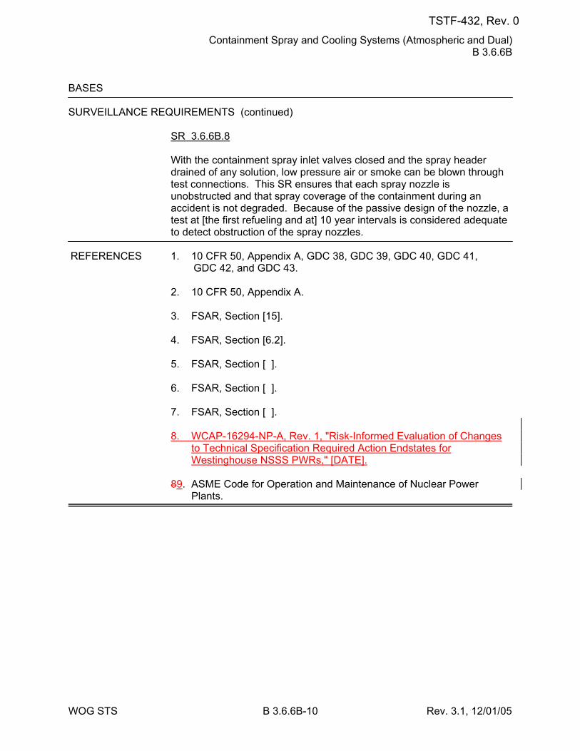
Containment Spray and Cooling Systems (Atmospheric and Dual) B 3.6.6B
WOG STS B 3.6.6B-10 Rev. 3.1, 12/01/05
BASES SURVEILLANCE REQUIREMENTS (continued)
SR 3.6.6B.8 With the containment spray inlet valves closed and the spray header drained of any solution, low pressure air or smoke can be blown through test connections. This SR ensures that each spray nozzle is unobstructed and that spray coverage of the containment during an accident is not degraded. Because of the passive design of the nozzle, a test at [the first refueling and at] 10 year intervals is considered adequate to detect obstruction of the spray nozzles.
REFERENCES 1. 10 CFR 50, Appendix A, GDC 38, GDC 39, GDC 40, GDC 41,
GDC 42, and GDC 43. 2. 10 CFR 50, Appendix A. 3. FSAR, Section [15]. 4. FSAR, Section [6.2]. 5. FSAR, Section [ ]. 6. FSAR, Section [ ].
7. FSAR, Section [ ]. 8. WCAP-16294-NP-A, Rev. 1, "Risk-Informed Evaluation of Changes
to Technical Specification Required Action Endstates for Westinghouse NSSS PWRs," [DATE].
89. ASME Code for Operation and Maintenance of Nuclear Power
Plants.
TSTF-432, Rev. 0
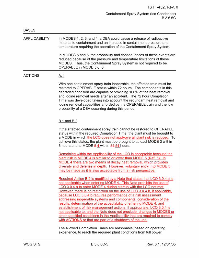
Containment Spray System (Ice Condenser) B 3.6.6C
WOG STS B 3.6.6C-5 Rev. 3.1, 12/01/05
BASES APPLICABILITY In MODES 1, 2, 3, and 4, a DBA could cause a release of radioactive
material to containment and an increase in containment pressure and temperature requiring the operation of the Containment Spray System.
In MODES 5 and 6, the probability and consequences of these events are reduced because of the pressure and temperature limitations of these MODES. Thus, the Containment Spray System is not required to be OPERABLE in MODE 5 or 6.
ACTIONS A.1
With one containment spray train inoperable, the affected train must be restored to OPERABLE status within 72 hours. The components in this degraded condition are capable of providing 100% of the heat removal and iodine removal needs after an accident. The 72 hour Completion Time was developed taking into account the redundant heat removal and iodine removal capabilities afforded by the OPERABLE train and the low probability of a DBA occurring during this period. B.1 and B.2 If the affected containment spray train cannot be restored to OPERABLE status within the required Completion Time, the plant must be brought to a MODE in which the LCO does not applyoverall plant risk is reduced. To achieve this status, the plant must be brought to at least MODE 3 within 6 hours and to MODE 5 4 within 84 54 hours. Remaining within the Applicability of the LCO is acceptable because the plant risk in MODE 4 is similar to or lower than MODE 5 (Ref. 5). In MODE 4 there are two means of decay heat removal, which provides diversity and defense in depth. However, voluntary entry into MODE 5 may be made as it is also acceptable from a risk perspective. Required Action B.2 is modified by a Note that states that LCO 3.0.4.a is not applicable when entering MODE 4. This Note prohibits the use of LCO 3.0.4.a to enter MODE 4 during startup with the LCO not met. However, there is no restriction on the use of LCO 3.0.4.b, if applicable, because LCO 3.0.4.b requires performance of a risk assessment addressing inoperable systems and components, consideration of the results, determination of the acceptability of entering MODE 4, and establishment of risk management actions, if appropriate. LCO 3.0.4 is not applicable to, and the Note does not preclude, changes in MODES or other specified conditions in the Applicability that are required to comply with ACTIONS or that are part of a shutdown of the unit. The allowed Completion Times are reasonable, based on operating experience, to reach the required plant conditions from full power
TSTF-432, Rev. 0
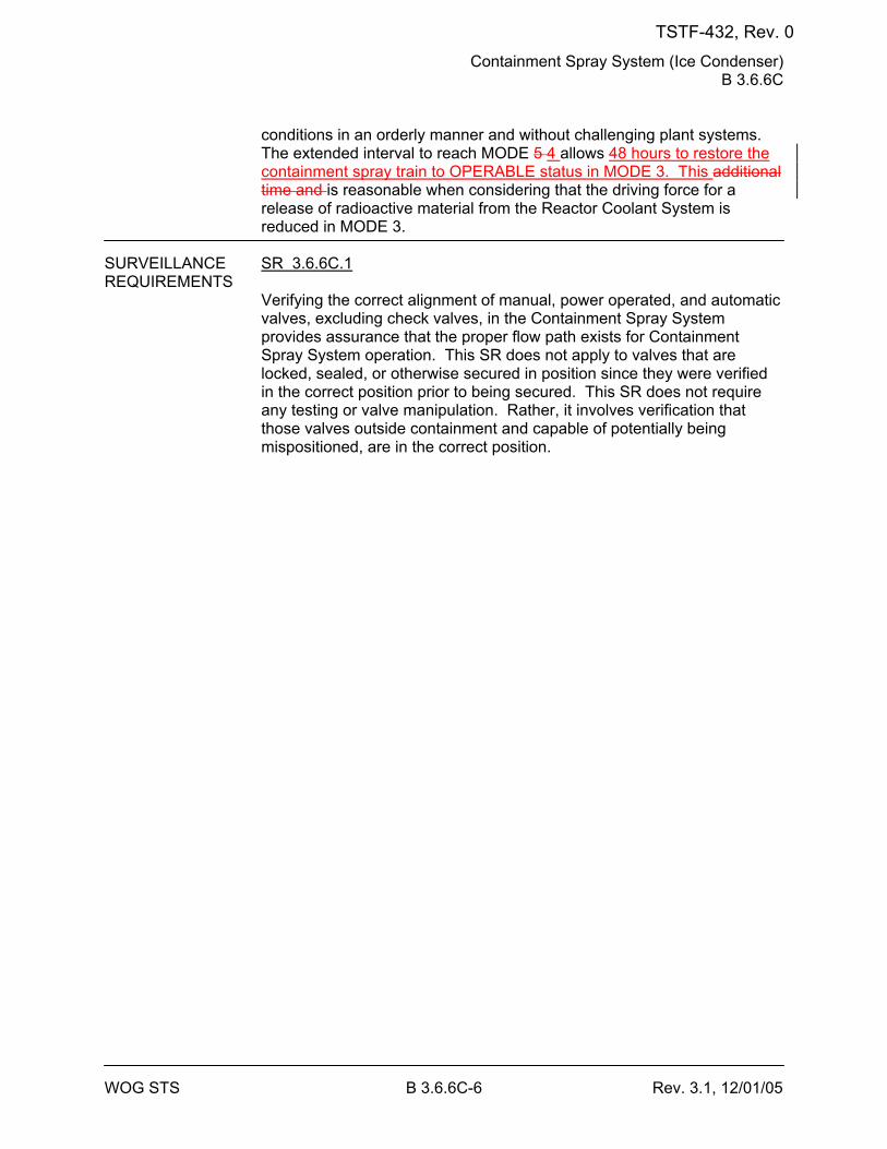
Containment Spray System (Ice Condenser) B 3.6.6C
WOG STS B 3.6.6C-6 Rev. 3.1, 12/01/05
conditions in an orderly manner and without challenging plant systems. The extended interval to reach MODE 5 4 allows 48 hours to restore the containment spray train to OPERABLE status in MODE 3. This additional time and is reasonable when considering that the driving force for a release of radioactive material from the Reactor Coolant System is reduced in MODE 3.
SURVEILLANCE SR 3.6.6C.1 REQUIREMENTS
Verifying the correct alignment of manual, power operated, and automatic valves, excluding check valves, in the Containment Spray System provides assurance that the proper flow path exists for Containment Spray System operation. This SR does not apply to valves that are locked, sealed, or otherwise secured in position since they were verified in the correct position prior to being secured. This SR does not require any testing or valve manipulation. Rather, it involves verification that those valves outside containment and capable of potentially being mispositioned, are in the correct position.
TSTF-432, Rev. 0
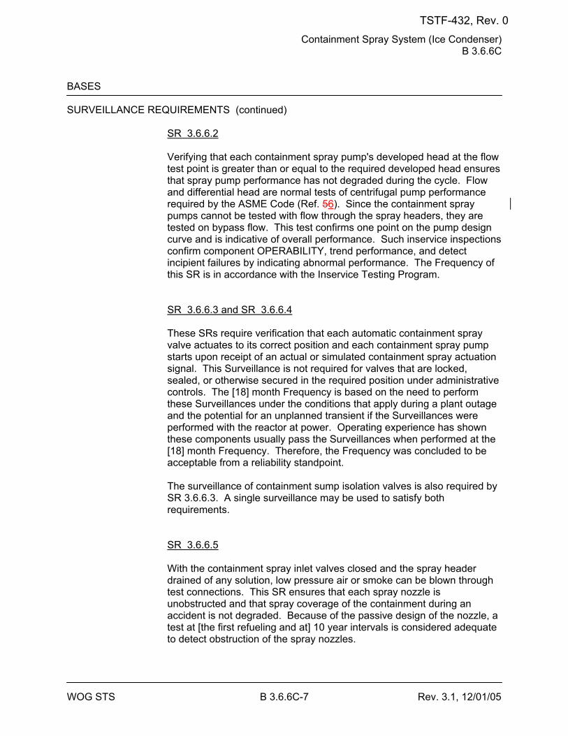
Containment Spray System (Ice Condenser) B 3.6.6C
WOG STS B 3.6.6C-7 Rev. 3.1, 12/01/05
BASES SURVEILLANCE REQUIREMENTS (continued)
SR 3.6.6.2 Verifying that each containment spray pump's developed head at the flow test point is greater than or equal to the required developed head ensures that spray pump performance has not degraded during the cycle. Flow and differential head are normal tests of centrifugal pump performance required by the ASME Code (Ref. 56). Since the containment spray pumps cannot be tested with flow through the spray headers, they are tested on bypass flow. This test confirms one point on the pump design curve and is indicative of overall performance. Such inservice inspections confirm component OPERABILITY, trend performance, and detect incipient failures by indicating abnormal performance. The Frequency of this SR is in accordance with the Inservice Testing Program. SR 3.6.6.3 and SR 3.6.6.4 These SRs require verification that each automatic containment spray valve actuates to its correct position and each containment spray pump starts upon receipt of an actual or simulated containment spray actuation signal. This Surveillance is not required for valves that are locked, sealed, or otherwise secured in the required position under administrative controls. The [18] month Frequency is based on the need to perform these Surveillances under the conditions that apply during a plant outage and the potential for an unplanned transient if the Surveillances were performed with the reactor at power. Operating experience has shown these components usually pass the Surveillances when performed at the [18] month Frequency. Therefore, the Frequency was concluded to be acceptable from a reliability standpoint. The surveillance of containment sump isolation valves is also required by SR 3.6.6.3. A single surveillance may be used to satisfy both requirements. SR 3.6.6.5 With the containment spray inlet valves closed and the spray header drained of any solution, low pressure air or smoke can be blown through test connections. This SR ensures that each spray nozzle is unobstructed and that spray coverage of the containment during an accident is not degraded. Because of the passive design of the nozzle, a test at [the first refueling and at] 10 year intervals is considered adequate to detect obstruction of the spray nozzles.
TSTF-432, Rev. 0
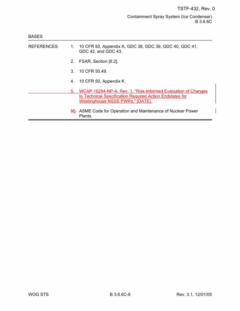
Containment Spray System (Ice Condenser) B 3.6.6C
WOG STS B 3.6.6C-8 Rev. 3.1, 12/01/05
BASES REFERENCES 1. 10 CFR 50, Appendix A, GDC 38, GDC 39, GDC 40, GDC 41,
GDC 42, and GDC 43. 2. FSAR, Section [6.2]. 3. 10 CFR 50.49. 4. 10 CFR 50, Appendix K. 5. WCAP-16294-NP-A, Rev. 1, "Risk-Informed Evaluation of Changes
to Technical Specification Required Action Endstates for Westinghouse NSSS PWRs," [DATE].
56. ASME Code for Operation and Maintenance of Nuclear Power
Plants.
TSTF-432, Rev. 0
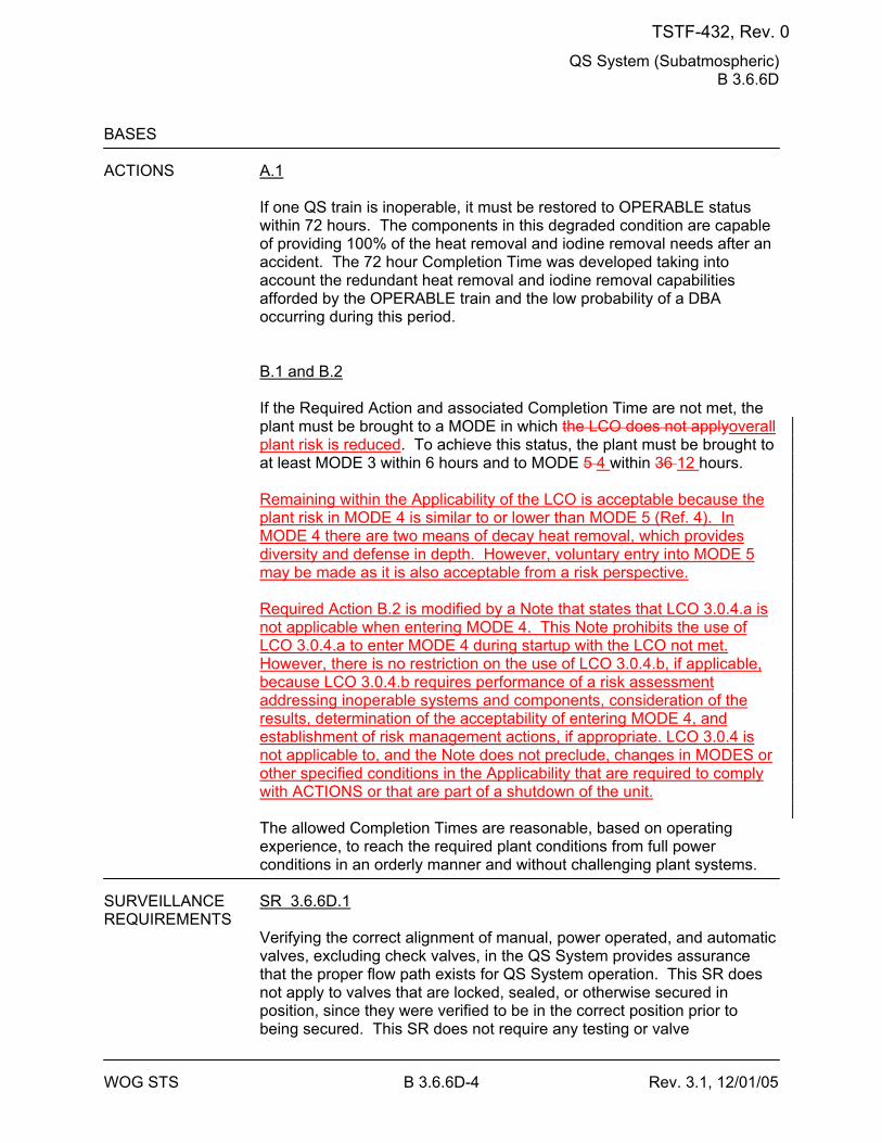
QS System (Subatmospheric) B 3.6.6D
WOG STS B 3.6.6D-4 Rev. 3.1, 12/01/05
BASES ACTIONS A.1
If one QS train is inoperable, it must be restored to OPERABLE status within 72 hours. The components in this degraded condition are capable of providing 100% of the heat removal and iodine removal needs after an accident. The 72 hour Completion Time was developed taking into account the redundant heat removal and iodine removal capabilities afforded by the OPERABLE train and the low probability of a DBA occurring during this period. B.1 and B.2 If the Required Action and associated Completion Time are not met, the plant must be brought to a MODE in which the LCO does not applyoverall plant risk is reduced. To achieve this status, the plant must be brought to at least MODE 3 within 6 hours and to MODE 5 4 within 36 12 hours. Remaining within the Applicability of the LCO is acceptable because the plant risk in MODE 4 is similar to or lower than MODE 5 (Ref. 4). In MODE 4 there are two means of decay heat removal, which provides diversity and defense in depth. However, voluntary entry into MODE 5 may be made as it is also acceptable from a risk perspective. Required Action B.2 is modified by a Note that states that LCO 3.0.4.a is not applicable when entering MODE 4. This Note prohibits the use of LCO 3.0.4.a to enter MODE 4 during startup with the LCO not met. However, there is no restriction on the use of LCO 3.0.4.b, if applicable, because LCO 3.0.4.b requires performance of a risk assessment addressing inoperable systems and components, consideration of the results, determination of the acceptability of entering MODE 4, and establishment of risk management actions, if appropriate. LCO 3.0.4 is not applicable to, and the Note does not preclude, changes in MODES or other specified conditions in the Applicability that are required to comply with ACTIONS or that are part of a shutdown of the unit. The allowed Completion Times are reasonable, based on operating experience, to reach the required plant conditions from full power conditions in an orderly manner and without challenging plant systems.
SURVEILLANCE SR 3.6.6D.1 REQUIREMENTS
Verifying the correct alignment of manual, power operated, and automatic valves, excluding check valves, in the QS System provides assurance that the proper flow path exists for QS System operation. This SR does not apply to valves that are locked, sealed, or otherwise secured in position, since they were verified to be in the correct position prior to being secured. This SR does not require any testing or valve
TSTF-432, Rev. 0
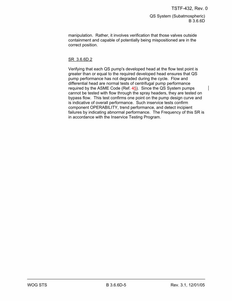
QS System (Subatmospheric) B 3.6.6D
WOG STS B 3.6.6D-5 Rev. 3.1, 12/01/05
manipulation. Rather, it involves verification that those valves outside containment and capable of potentially being mispositioned are in the correct position. SR 3.6.6D.2 Verifying that each QS pump's developed head at the flow test point is greater than or equal to the required developed head ensures that QS pump performance has not degraded during the cycle. Flow and differential head are normal tests of centrifugal pump performance required by the ASME Code (Ref. 45). Since the QS System pumps cannot be tested with flow through the spray headers, they are tested on bypass flow. This test confirms one point on the pump design curve and is indicative of overall performance. Such inservice tests confirm component OPERABILITY, trend performance, and detect incipient failures by indicating abnormal performance. The Frequency of this SR is in accordance with the Inservice Testing Program.
TSTF-432, Rev. 0
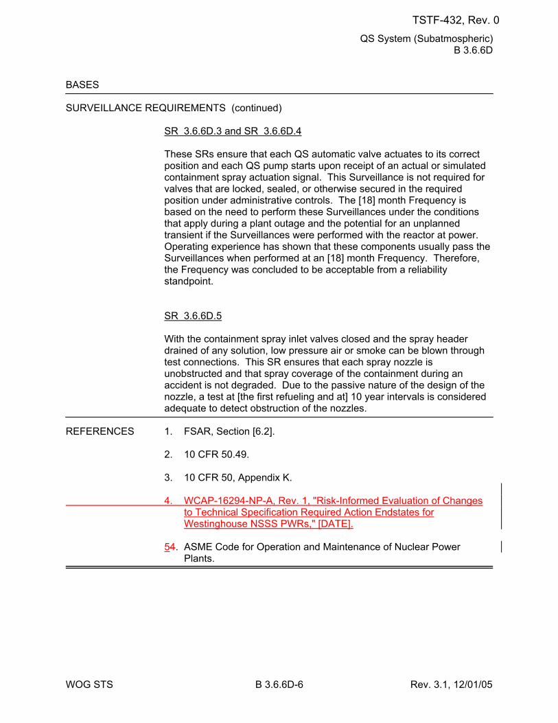
QS System (Subatmospheric) B 3.6.6D
WOG STS B 3.6.6D-6 Rev. 3.1, 12/01/05
BASES SURVEILLANCE REQUIREMENTS (continued)
SR 3.6.6D.3 and SR 3.6.6D.4
These SRs ensure that each QS automatic valve actuates to its correct position and each QS pump starts upon receipt of an actual or simulated containment spray actuation signal. This Surveillance is not required for valves that are locked, sealed, or otherwise secured in the required position under administrative controls. The [18] month Frequency is based on the need to perform these Surveillances under the conditions that apply during a plant outage and the potential for an unplanned transient if the Surveillances were performed with the reactor at power. Operating experience has shown that these components usually pass the Surveillances when performed at an [18] month Frequency. Therefore, the Frequency was concluded to be acceptable from a reliability standpoint. SR 3.6.6D.5 With the containment spray inlet valves closed and the spray header drained of any solution, low pressure air or smoke can be blown through test connections. This SR ensures that each spray nozzle is unobstructed and that spray coverage of the containment during an accident is not degraded. Due to the passive nature of the design of the nozzle, a test at [the first refueling and at] 10 year intervals is considered adequate to detect obstruction of the nozzles.
REFERENCES 1. FSAR, Section [6.2]. 2. 10 CFR 50.49. 3. 10 CFR 50, Appendix K. 4. WCAP-16294-NP-A, Rev. 1, "Risk-Informed Evaluation of Changes
to Technical Specification Required Action Endstates for Westinghouse NSSS PWRs," [DATE].
54. ASME Code for Operation and Maintenance of Nuclear Power
Plants.
TSTF-432, Rev. 0
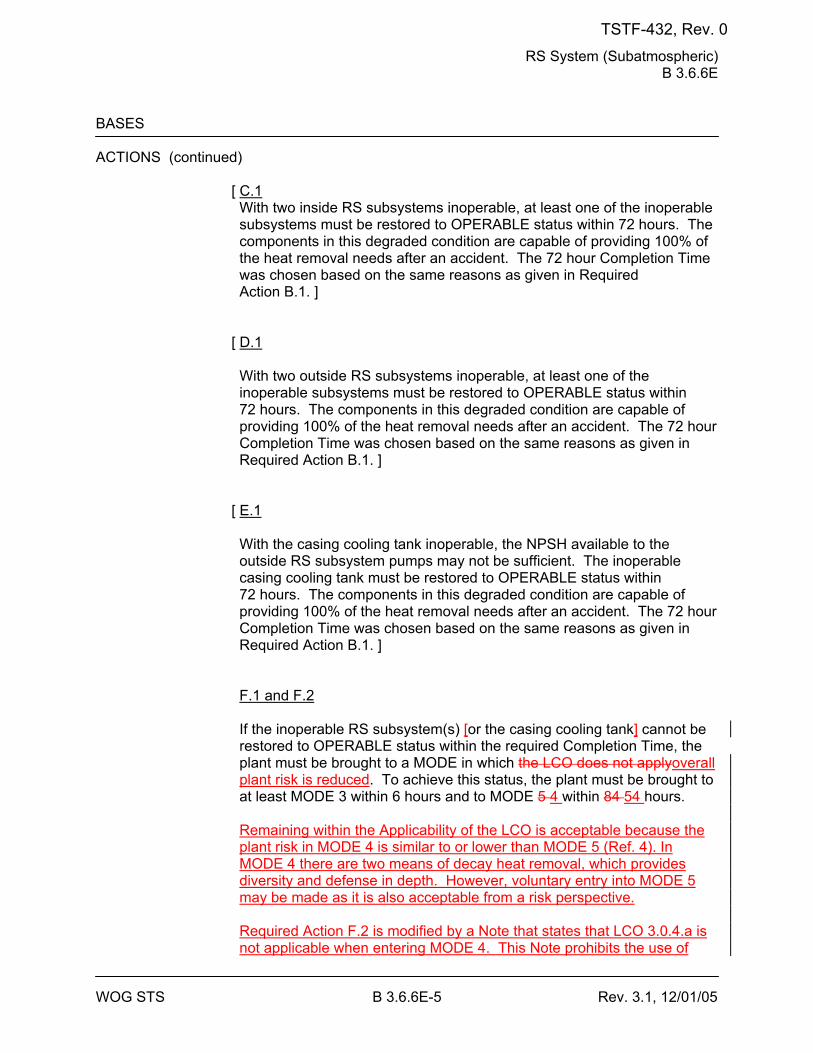
RS System (Subatmospheric) B 3.6.6E
WOG STS B 3.6.6E-5 Rev. 3.1, 12/01/05
BASES ACTIONS (continued)
[ C.1 With two inside RS subsystems inoperable, at least one of the inoperable subsystems must be restored to OPERABLE status within 72 hours. The components in this degraded condition are capable of providing 100% of the heat removal needs after an accident. The 72 hour Completion Time was chosen based on the same reasons as given in Required Action B.1. ]
[ D.1 With two outside RS subsystems inoperable, at least one of the inoperable subsystems must be restored to OPERABLE status within 72 hours. The components in this degraded condition are capable of providing 100% of the heat removal needs after an accident. The 72 hour Completion Time was chosen based on the same reasons as given in Required Action B.1. ]
[ E.1 With the casing cooling tank inoperable, the NPSH available to the outside RS subsystem pumps may not be sufficient. The inoperable casing cooling tank must be restored to OPERABLE status within 72 hours. The components in this degraded condition are capable of providing 100% of the heat removal needs after an accident. The 72 hour Completion Time was chosen based on the same reasons as given in Required Action B.1. ] F.1 and F.2 If the inoperable RS subsystem(s) [or the casing cooling tank] cannot be restored to OPERABLE status within the required Completion Time, the plant must be brought to a MODE in which the LCO does not applyoverall plant risk is reduced. To achieve this status, the plant must be brought to at least MODE 3 within 6 hours and to MODE 5 4 within 84 54 hours. Remaining within the Applicability of the LCO is acceptable because the plant risk in MODE 4 is similar to or lower than MODE 5 (Ref. 4). In MODE 4 there are two means of decay heat removal, which provides diversity and defense in depth. However, voluntary entry into MODE 5 may be made as it is also acceptable from a risk perspective. Required Action F.2 is modified by a Note that states that LCO 3.0.4.a is not applicable when entering MODE 4. This Note prohibits the use of
TSTF-432, Rev. 0
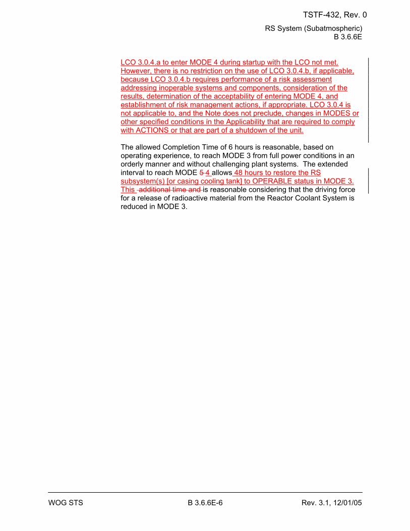
RS System (Subatmospheric) B 3.6.6E
WOG STS B 3.6.6E-6 Rev. 3.1, 12/01/05
LCO 3.0.4.a to enter MODE 4 during startup with the LCO not met. However, there is no restriction on the use of LCO 3.0.4.b, if applicable, because LCO 3.0.4.b requires performance of a risk assessment addressing inoperable systems and components, consideration of the results, determination of the acceptability of entering MODE 4, and establishment of risk management actions, if appropriate. LCO 3.0.4 is not applicable to, and the Note does not preclude, changes in MODES or other specified conditions in the Applicability that are required to comply with ACTIONS or that are part of a shutdown of the unit. The allowed Completion Time of 6 hours is reasonable, based on operating experience, to reach MODE 3 from full power conditions in an orderly manner and without challenging plant systems. The extended interval to reach MODE 5 4 allows 48 hours to restore the RS subsystem(s) [or casing cooling tank] to OPERABLE status in MODE 3. This additional time and is reasonable considering that the driving force for a release of radioactive material from the Reactor Coolant System is reduced in MODE 3.
TSTF-432, Rev. 0
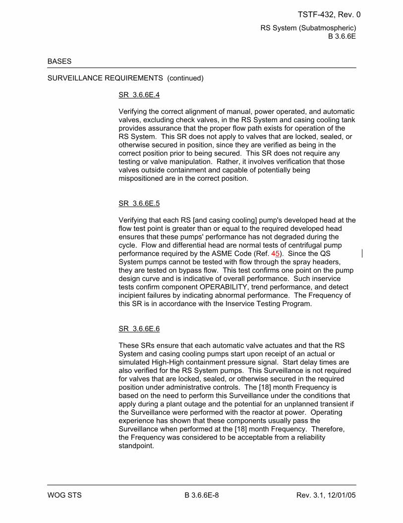
RS System (Subatmospheric) B 3.6.6E
WOG STS B 3.6.6E-8 Rev. 3.1, 12/01/05
BASES SURVEILLANCE REQUIREMENTS (continued)
SR 3.6.6E.4 Verifying the correct alignment of manual, power operated, and automatic valves, excluding check valves, in the RS System and casing cooling tank provides assurance that the proper flow path exists for operation of the RS System. This SR does not apply to valves that are locked, sealed, or otherwise secured in position, since they are verified as being in the correct position prior to being secured. This SR does not require any testing or valve manipulation. Rather, it involves verification that those valves outside containment and capable of potentially being mispositioned are in the correct position. SR 3.6.6E.5 Verifying that each RS [and casing cooling] pump's developed head at the flow test point is greater than or equal to the required developed head ensures that these pumps' performance has not degraded during the cycle. Flow and differential head are normal tests of centrifugal pump performance required by the ASME Code (Ref. 45). Since the QS System pumps cannot be tested with flow through the spray headers, they are tested on bypass flow. This test confirms one point on the pump design curve and is indicative of overall performance. Such inservice tests confirm component OPERABILITY, trend performance, and detect incipient failures by indicating abnormal performance. The Frequency of this SR is in accordance with the Inservice Testing Program. SR 3.6.6E.6 These SRs ensure that each automatic valve actuates and that the RS System and casing cooling pumps start upon receipt of an actual or simulated High-High containment pressure signal. Start delay times are also verified for the RS System pumps. This Surveillance is not required for valves that are locked, sealed, or otherwise secured in the required position under administrative controls. The [18] month Frequency is based on the need to perform this Surveillance under the conditions that apply during a plant outage and the potential for an unplanned transient if the Surveillance were performed with the reactor at power. Operating experience has shown that these components usually pass the Surveillance when performed at the [18] month Frequency. Therefore, the Frequency was considered to be acceptable from a reliability standpoint.
TSTF-432, Rev. 0
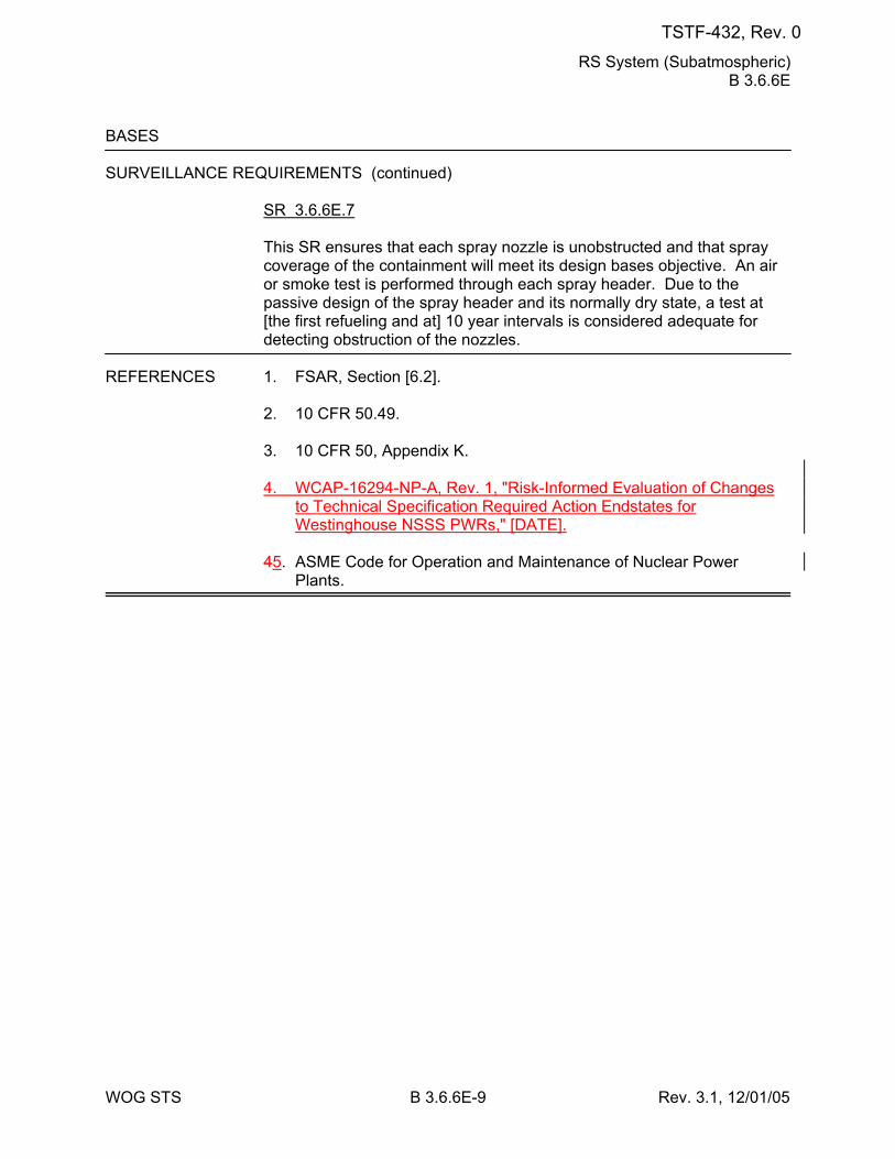
RS System (Subatmospheric) B 3.6.6E
WOG STS B 3.6.6E-9 Rev. 3.1, 12/01/05
BASES SURVEILLANCE REQUIREMENTS (continued)
SR 3.6.6E.7 This SR ensures that each spray nozzle is unobstructed and that spray coverage of the containment will meet its design bases objective. An air or smoke test is performed through each spray header. Due to the passive design of the spray header and its normally dry state, a test at [the first refueling and at] 10 year intervals is considered adequate for detecting obstruction of the nozzles.
REFERENCES 1. FSAR, Section [6.2]. 2. 10 CFR 50.49.
3. 10 CFR 50, Appendix K. 4. WCAP-16294-NP-A, Rev. 1, "Risk-Informed Evaluation of Changes
to Technical Specification Required Action Endstates for Westinghouse NSSS PWRs," [DATE].
45. ASME Code for Operation and Maintenance of Nuclear Power
Plants.
TSTF-432, Rev. 0
Spray Additive System (Atmospheric, Subatmospheric, Ice Condenser, and Dual) B 3.6.7
WOG STS B 3.6.7-3 Rev. 3.0, 03/31/04
BASES LCO (continued)
spray flow until the Containment Spray System suction path is switched from the RWST to the containment sump, and to raise the average spray solution pH to a level conducive to iodine removal, namely, to between [7.2 and 11.0]. This pH range maximizes the effectiveness of the iodine removal mechanism without introducing conditions that may induce caustic stress corrosion cracking of mechanical system components. In addition, it is essential that valves in the Spray Additive System flow paths are properly positioned and that automatic valves are capable of activating to their correct positions.
APPLICABILITY In MODES 1, 2, 3, and 4, a DBA could cause a release of radioactive
material to containment requiring the operation of the Spray Additive System. The Spray Additive System assists in reducing the iodine fission product inventory prior to release to the environment.
In MODES 5 and 6, the probability and consequences of these events are reduced due to the pressure and temperature limitations in these MODES. Thus, the Spray Additive System is not required to be OPERABLE in MODE 5 or 6.
ACTIONS A.1
If the Spray Additive System is inoperable, it must be restored to OPERABLE within 72 hours. The pH adjustment of the Containment Spray System flow for corrosion protection and iodine removal enhancement is reduced in this condition. The Containment Spray System would still be available and would remove some iodine from the containment atmosphere in the event of a DBA. The 72 hour Completion Time takes into account the redundant flow path capabilities and the low probability of the worst case DBA occurring during this period. B.1 and B.2 If the Spray Additive System cannot be restored to OPERABLE status within the required Completion Time, the plant must be brought to a MODE in which the LCO does not applyoverall plant risk is reduced. To achieve this status, the plant must be brought to at least MODE 3 within 6 hours and to MODE 5 4 within 84 54hours. Remaining within the Applicability of the LCO is acceptable because the plant risk in MODE 4 is similar to or lower than MODE 5 (Ref. 2). In MODE 4 there are two means of decay heat removal, which provides diversity and defense in depth. However, voluntary entry into MODE 5 may be made as it is also acceptable from a risk perspective.
TSTF-432, Rev. 0
Spray Additive System (Atmospheric, Subatmospheric, Ice Condenser, and Dual) B 3.6.7
WOG STS B 3.6.7-4 Rev. 3.0, 03/31/04
Required Action B.2 is modified by a Note that states that LCO 3.0.4.a is not applicable when entering MODE 4. This Note prohibits the use of LCO 3.0.4.a to enter MODE 4 during startup with the LCO not met. However, there is no restriction on the use of LCO 3.0.4.b, if applicable, because LCO 3.0.4.b requires performance of a risk assessment addressing inoperable systems and components, consideration of the results, determination of the acceptability of entering MODE 4, and establishment of risk management actions, if appropriate. LCO 3.0.4 is not applicable to, and the Note does not preclude, changes in MODES or other specified conditions in the Applicability that are required to comply with ACTIONS or that are part of a shutdown of the unit. The allowed Completion Time of 6 hours is reasonable, based on operating experience, to reach MODE 3 from full power conditions in an orderly manner and without challenging plant systems. The extended interval to reach MODE 5 4 allows 48 hours to restore for restoration of the Spray
TSTF-432, Rev. 0
Spray Additive System (Atmospheric, Subatmospheric, Ice Condenser, and Dual) B 3.6.7
WOG STS B 3.6.7-5 Rev. 3.0, 03/31/04
BASES ACTIONS (continued)
Additive System to OPERABLE status in MODE 3 and 36 hours to reach MODE 5. This is reasonable when considering the reduced pressure and temperature conditions in MODE 3 for the release of radioactive material from the Reactor Coolant System.
SURVEILLANCE SR 3.6.7.1 REQUIREMENTS
Verifying the correct alignment of Spray Additive System manual, power operated, and automatic valves in the spray additive flow path provides assurance that the system is able to provide additive to the Containment Spray System in the event of a DBA. This SR does not apply to valves that are locked, sealed, or otherwise secured in position, since these valves were verified to be in the correct position prior to locking, sealing, or securing. This SR does not require any testing or valve manipulation. Rather, it involves verification that those valves outside containment and capable of potentially being mispositioned are in the correct position. SR 3.6.7.2 To provide effective iodine removal, the containment spray must be an alkaline solution. Since the RWST contents are normally acidic, the volume of the spray additive tank must provide a sufficient volume of spray additive to adjust pH for all water injected. This SR is performed to verify the availability of sufficient NaOH solution in the Spray Additive System. The 184 day Frequency was developed based on the low probability of an undetected change in tank volume occurring during the SR interval (the tank is isolated during normal unit operations). Tank level is also indicated and alarmed in the control room, so that there is high confidence that a substantial change in level would be detected. SR 3.6.7.3 This SR provides verification of the NaOH concentration in the spray additive tank and is sufficient to ensure that the spray solution being injected into containment is at the correct pH level. The 184 day Frequency is sufficient to ensure that the concentration level of NaOH in the spray additive tank remains within the established limits. This is based on the low likelihood of an uncontrolled change in concentration (the tank is normally isolated) and the probability that any substantial variance in tank volume will be detected.
TSTF-432, Rev. 0
Spray Additive System (Atmospheric, Subatmospheric, Ice Condenser, and Dual) B 3.6.7
WOG STS B 3.6.7-6 Rev. 3.0, 03/31/04
BASES SURVEILLANCE REQUIREMENTS (continued)
SR 3.6.7.4
This SR provides verification that each automatic valve in the Spray Additive System flow path actuates to its correct position. This Surveillance is not required for valves that are locked, sealed, or otherwise secured in the required position under administrative controls. The [18] month Frequency is based on the need to perform this Surveillance under the conditions that apply during a plant outage and the potential for an unplanned transient if the Surveillance were performed with the reactor at power. Operating experience has shown that these components usually pass the Surveillance when performed at the [18] month Frequency. Therefore, the Frequency was concluded to be acceptable from a reliability standpoint. SR 3.6.7.5 To ensure that the correct pH level is established in the borated water solution provided by the Containment Spray System, the flow rate in the Spray Additive System is verified once every 5 years. This SR provides assurance that the correct amount of NaOH will be metered into the flow path upon Containment Spray System initiation. Due to the passive nature of the spray additive flow controls, the 5 year Frequency is sufficient to identify component degradation that may affect flow rate.
REFERENCES 1. FSAR, Chapter [15]. 2. WCAP-16294-NP-A, Rev. 1, "Risk-Informed Evaluation of Changes
to Technical Specification Required Action Endstates for Westinghouse NSSS PWRs," [DATE].
TSTF-432, Rev. 0
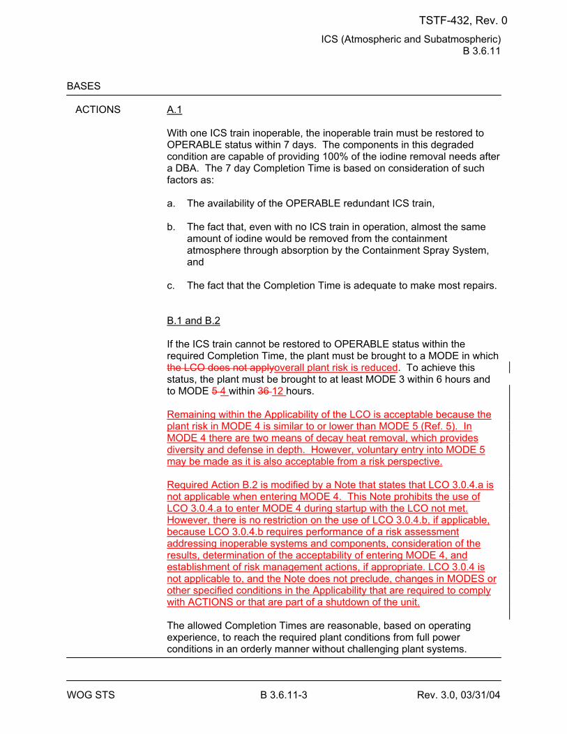
ICS (Atmospheric and Subatmospheric) B 3.6.11
WOG STS B 3.6.11-3 Rev. 3.0, 03/31/04
BASES
ACTIONS A.1
With one ICS train inoperable, the inoperable train must be restored to OPERABLE status within 7 days. The components in this degraded condition are capable of providing 100% of the iodine removal needs after a DBA. The 7 day Completion Time is based on consideration of such factors as: a. The availability of the OPERABLE redundant ICS train, b. The fact that, even with no ICS train in operation, almost the same
amount of iodine would be removed from the containment atmosphere through absorption by the Containment Spray System, and
c. The fact that the Completion Time is adequate to make most repairs. B.1 and B.2 If the ICS train cannot be restored to OPERABLE status within the required Completion Time, the plant must be brought to a MODE in which the LCO does not applyoverall plant risk is reduced. To achieve this status, the plant must be brought to at least MODE 3 within 6 hours and to MODE 5 4 within 36 12 hours. Remaining within the Applicability of the LCO is acceptable because the plant risk in MODE 4 is similar to or lower than MODE 5 (Ref. 5). In MODE 4 there are two means of decay heat removal, which provides diversity and defense in depth. However, voluntary entry into MODE 5 may be made as it is also acceptable from a risk perspective. Required Action B.2 is modified by a Note that states that LCO 3.0.4.a is not applicable when entering MODE 4. This Note prohibits the use of LCO 3.0.4.a to enter MODE 4 during startup with the LCO not met. However, there is no restriction on the use of LCO 3.0.4.b, if applicable, because LCO 3.0.4.b requires performance of a risk assessment addressing inoperable systems and components, consideration of the results, determination of the acceptability of entering MODE 4, and establishment of risk management actions, if appropriate. LCO 3.0.4 is not applicable to, and the Note does not preclude, changes in MODES or other specified conditions in the Applicability that are required to comply with ACTIONS or that are part of a shutdown of the unit. The allowed Completion Times are reasonable, based on operating experience, to reach the required plant conditions from full power conditions in an orderly manner without challenging plant systems.
TSTF-432, Rev. 0
ICS (Atmospheric and Subatmospheric) B 3.6.11
WOG STS B 3.6.11-5 Rev. 3.0, 03/31/04
BASES SURVEILLANCE REQUIREMENTS (continued)
SR 3.6.11.2 This SR verifies that the required ICS filter testing is performed in accordance with the Ventilation Filter Testing Program (VFTP). The VFTP includes testing HEPA filter performance, charcoal adsorber efficiency, minimum system flow rate, and the physical properties of the activated charcoal (general use and following specific operations). Specific test frequencies and additional information are discussed in detail in the VFTP. SR 3.6.11.3 The automatic startup test verifies that both trains of equipment start upon receipt of an actual or simulated test signal. The [18] month Frequency is based on the need to perform this Surveillance under the conditions that apply during a plant outage and the potential for an unplanned transient if the Surveillance were performed with the reactor at power. Operating experience has shown that these components usually pass the Surveillance when performed at the [18] month Frequency. Therefore, the Frequency was concluded to be acceptable from a reliability standpoint. Furthermore, the Frequency was developed considering that the system equipment OPERABILITY is demonstrated at a 31 day Frequency by SR 3.6.11.1.
[ SR 3.6.11.4 The ICS filter bypass dampers are tested to verify OPERABILITY. The dampers are in the bypass position during normal operation and must reposition for accident operation to draw air through the filters. The [18] month Frequency is considered to be acceptable based on the damper reliability and design, the mild environmental conditions in the vicinity of the dampers, and the fact that operating experience has shown that the dampers usually pass the Surveillance when performed at the [18] month Frequency. ]
REFERENCES 1. 10 CFR 50, Appendix A, GDC 41, GDC 42, and GDC 43. 2. FSAR, Section [6.5]. 3. Regulatory Guide 1.52, Revision [2]. 4. FSAR, Chapter [15].
TSTF-432, Rev. 0
ICS (Atmospheric and Subatmospheric) B 3.6.11
WOG STS B 3.6.11-6 Rev. 3.0, 03/31/04
5. WCAP-16294-NP-A, Rev. 1, "Risk-Informed Evaluation of Changes to Technical Specification Required Action Endstates for Westinghouse NSSS PWRs," [DATE].
TSTF-432, Rev. 0
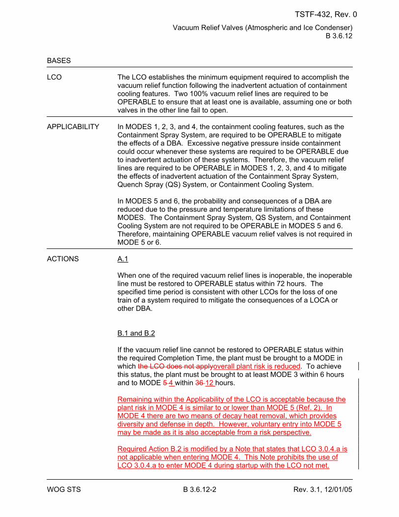
Vacuum Relief Valves (Atmospheric and Ice Condenser) B 3.6.12
WOG STS B 3.6.12-2 Rev. 3.1, 12/01/05
BASES LCO The LCO establishes the minimum equipment required to accomplish the
vacuum relief function following the inadvertent actuation of containment cooling features. Two 100% vacuum relief lines are required to be OPERABLE to ensure that at least one is available, assuming one or both valves in the other line fail to open.
APPLICABILITY In MODES 1, 2, 3, and 4, the containment cooling features, such as the
Containment Spray System, are required to be OPERABLE to mitigate the effects of a DBA. Excessive negative pressure inside containment could occur whenever these systems are required to be OPERABLE due to inadvertent actuation of these systems. Therefore, the vacuum relief lines are required to be OPERABLE in MODES 1, 2, 3, and 4 to mitigate the effects of inadvertent actuation of the Containment Spray System, Quench Spray (QS) System, or Containment Cooling System.
In MODES 5 and 6, the probability and consequences of a DBA are reduced due to the pressure and temperature limitations of these MODES. The Containment Spray System, QS System, and Containment Cooling System are not required to be OPERABLE in MODES 5 and 6. Therefore, maintaining OPERABLE vacuum relief valves is not required in MODE 5 or 6.
ACTIONS A.1
When one of the required vacuum relief lines is inoperable, the inoperable line must be restored to OPERABLE status within 72 hours. The specified time period is consistent with other LCOs for the loss of one train of a system required to mitigate the consequences of a LOCA or other DBA. B.1 and B.2 If the vacuum relief line cannot be restored to OPERABLE status within the required Completion Time, the plant must be brought to a MODE in which the LCO does not applyoverall plant risk is reduced. To achieve this status, the plant must be brought to at least MODE 3 within 6 hours and to MODE 5 4 within 36 12 hours. Remaining within the Applicability of the LCO is acceptable because the plant risk in MODE 4 is similar to or lower than MODE 5 (Ref. 2). In MODE 4 there are two means of decay heat removal, which provides diversity and defense in depth. However, voluntary entry into MODE 5 may be made as it is also acceptable from a risk perspective. Required Action B.2 is modified by a Note that states that LCO 3.0.4.a is not applicable when entering MODE 4. This Note prohibits the use of LCO 3.0.4.a to enter MODE 4 during startup with the LCO not met.
TSTF-432, Rev. 0
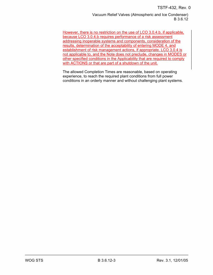
Vacuum Relief Valves (Atmospheric and Ice Condenser) B 3.6.12
WOG STS B 3.6.12-3 Rev. 3.1, 12/01/05
However, there is no restriction on the use of LCO 3.0.4.b, if applicable, because LCO 3.0.4.b requires performance of a risk assessment addressing inoperable systems and components, consideration of the results, determination of the acceptability of entering MODE 4, and establishment of risk management actions, if appropriate. LCO 3.0.4 is not applicable to, and the Note does not preclude, changes in MODES or other specified conditions in the Applicability that are required to comply with ACTIONS or that are part of a shutdown of the unit. The allowed Completion Times are reasonable, based on operating experience, to reach the required plant conditions from full power conditions in an orderly manner and without challenging plant systems.
TSTF-432, Rev. 0
Vacuum Relief Valves (Atmospheric and Ice Condenser) B 3.6.12
WOG STS B 3.6.12-4 Rev. 3.1, 12/01/05
BASES SURVEILLANCE SR 3.6.12.1 REQUIREMENTS
This SR cites the Inservice Testing Program, which establishes the requirement that inservice testing of the ASME Code Class 1, 2, and 3 pumps and valves shall be performed in accordance with the ASME Code (Ref. 23). Therefore, SR Frequency is governed by the Inservice Testing Program.
REFERENCES 1. FSAR, Section [6.2]. 2. WCAP-16294-NP-A, Rev. 1, "Risk-Informed Evaluation of Changes
to Technical Specification Required Action Endstates for Westinghouse NSSS PWRs," [DATE].
23. ASME Code for Operation and Maintenance of Nuclear Power
Plants.
TSTF-432, Rev. 0
SBACS (Dual and Ice Condenser) B 3.6.13
WOG STS B 3.6.13-3 Rev. 3.0, 03/31/04
BASES LCO In the event of a DBA, one SBACS train is required to provide the
minimum particulate iodine removal assumed in the safety analysis. Two trains of the SBACS must be OPERABLE to ensure that at least one train will operate, assuming that the other train is disabled by a single active failure.
APPLICABILITY In MODES 1, 2, 3, and 4, a DBA could lead to fission product release to
containment that leaks to the shield building. The large break LOCA, on which this system's design is based, is a full power event. Less severe LOCAs and leakage still require the system to be OPERABLE throughout these MODES. The probability and severity of a LOCA decrease as core power and Reactor Coolant System pressure decrease. With the reactor shut down, the probability of release of radioactivity resulting from such an accident is low.
In MODES 5 and 6, the probability and consequences of a DBA are low due to the pressure and temperature limitations in these MODES. Under these conditions, the Filtration System is not required to be OPERABLE (although one or more trains may be operating for other reasons, such as habitability during maintenance in the shield building annulus).
ACTIONS A.1
With one SBACS train inoperable, the inoperable train must be restored to OPERABLE status within 7 days. The components in this degraded condition are capable of providing 100% of the iodine removal needs after a DBA. The 7 day Completion Time is based on consideration of such factors as the availability of the OPERABLE redundant SBACS train and the low probability of a DBA occurring during this period. The Completion Time is adequate to make most repairs. B.1 and B.2 If the SBACS train cannot be restored to OPERABLE status within the required Completion Time, the plant must be brought to a MODE in which the LCO does not applyoverall plant risk is reduced. To achieve this status, the plant must be brought to at least MODE 3 within 6 hours and to MODE 5 4 within 36 12 hours. Remaining within the Applicability of the LCO is acceptable because the plant risk in MODE 4 is similar to or lower than MODE 5 (Ref. 4). In MODE 4 there are two means of decay heat removal, which provides diversity and defense in depth. However, voluntary entry into MODE 5 may be made as it is also acceptable from a risk perspective. Required Action B.2 is modified by a Note that states that LCO 3.0.4.a is not applicable when entering MODE 4. This Note prohibits the use of
TSTF-432, Rev. 0
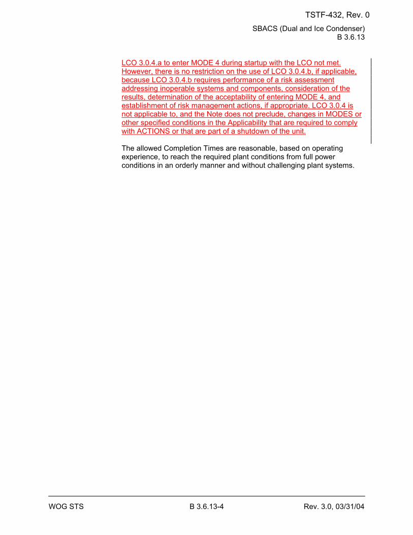
SBACS (Dual and Ice Condenser) B 3.6.13
WOG STS B 3.6.13-4 Rev. 3.0, 03/31/04
LCO 3.0.4.a to enter MODE 4 during startup with the LCO not met. However, there is no restriction on the use of LCO 3.0.4.b, if applicable, because LCO 3.0.4.b requires performance of a risk assessment addressing inoperable systems and components, consideration of the results, determination of the acceptability of entering MODE 4, and establishment of risk management actions, if appropriate. LCO 3.0.4 is not applicable to, and the Note does not preclude, changes in MODES or other specified conditions in the Applicability that are required to comply with ACTIONS or that are part of a shutdown of the unit. The allowed Completion Times are reasonable, based on operating experience, to reach the required plant conditions from full power conditions in an orderly manner and without challenging plant systems.
TSTF-432, Rev. 0
SBACS (Dual and Ice Condenser) B 3.6.13
WOG STS B 3.6.13-6 Rev. 3.0, 03/31/04
BASES SURVEILLANCE REQUIREMENTS (continued)
[ SR 3.6.13.4 The SBACS filter bypass dampers are tested to verify OPERABILITY. The dampers are in the bypass position during normal operation and must reposition for accident operation to draw air through the filters. The [18] month Frequency is considered to be acceptable based on damper reliability and design, mild environmental conditions in the vicinity of the dampers, and the fact that operating experience has shown that the dampers usually pass the Surveillance when performed at the [18] month Frequency. ] SR 3.6.13.5 The proper functioning of the fans, dampers, filters, adsorbers, etc., as a system is verified by the ability of each train to produce the required system flow rate. The [18] month Frequency on a STAGGERED TEST BASIS is consistent with Regulatory Guide 1.52 (Ref. 45) guidance for functional testing.
REFERENCES 1. 10 CFR 50, Appendix A, GDC 41. 2. FSAR, Section [6.5]. 3. FSAR, Chapter [15]. 4. WCAP-16294-NP-A, Rev. 1, "Risk-Informed Evaluation of Changes
to Technical Specification Required Action Endstates for Westinghouse NSSS PWRs," [DATE].
45. Regulatory Guide 1.52, Revision [2].
TSTF-432, Rev. 0
ARS (Ice Condenser) B 3.6.14
WOG STS B 3.6.14-4 Rev. 3.0, 03/31/04
BASES ACTIONS (continued)
B.1 and B.2 If the ARS train cannot be restored to OPERABLE status within the required Completion Time, the plant must be brought to a MODE in which the LCO does not applyoverall plant risk is reduced. To achieve this status, the plant must be brought to at least MODE 3 within 6 hours and to MODE 5 4 within 36 12 hours. Remaining within the Applicability of the LCO is acceptable because the plant risk in MODE 4 is similar to or lower than MODE 5 (Ref. 3). In MODE 4 there are two means of decay heat removal, which provides diversity and defense in depth. However, voluntary entry into MODE 5 may be made as it is also acceptable from a risk perspective. Required Action B.2 is modified by a Note that states that LCO 3.0.4.a is not applicable when entering MODE 4. This Note prohibits the use of LCO 3.0.4.a to enter MODE 4 during startup with the LCO not met. However, there is no restriction on the use of LCO 3.0.4.b, if applicable, because LCO 3.0.4.b requires performance of a risk assessment addressing inoperable systems and components, consideration of the results, determination of the acceptability of entering MODE 4, and establishment of risk management actions, if appropriate. LCO 3.0.4 is not applicable to, and the Note does not preclude, changes in MODES or other specified conditions in the Applicability that are required to comply with ACTIONS or that are part of a shutdown of the unit. The allowed Completion Times are reasonable, based on operating experience, to reach the required plant conditions from full power conditions in an orderly manner and without challenging plant systems.
SURVEILLANCE SR 3.6.14.1 REQUIREMENTS
Verifying that each ARS fan starts on an actual or simulated actuation signal, after a delay ≥ [9.0] minutes and ≤ [11.0] minutes, and operates for ≥ 15 minutes is sufficient to ensure that all fans are OPERABLE and that all associated controls and time delays are functioning properly. It also ensures that blockage, fan and/or motor failure, or excessive vibration can be detected for corrective action. The [92] day Frequency was developed considering the known reliability of fan motors and controls and the two train redundancy available. SR 3.6.14.2 Verifying ARS fan motor current to be at rated speed with the return air dampers closed confirms one operating condition of the fan. This test is
TSTF-432, Rev. 0
ARS (Ice Condenser) B 3.6.14
WOG STS B 3.6.14-6 Rev. 3.0, 03/31/04
BASES SURVEILLANCE REQUIREMENTS (continued)
[ SR 3.6.14.4 Verifying the OPERABILITY of the motor operated valve in the Hydrogen Skimmer System hydrogen collection header to the lower containment compartment provides assurance that the proper flow path will exist when the valve receives an actuation signal. This Surveillance is not required for valves that are locked, sealed, or otherwise secured in the required position under administrative controls. This Surveillance also confirms that the time delay to open is within specified tolerances. The 92 day Frequency was developed considering the known reliability of the motor operated valves and controls and the two train redundancy available. Operating experience has also shown this Frequency to be acceptable. ]
REFERENCES 1. FSAR, Section [6.2]. 2. 10 CFR 50, Appendix K. 3. WCAP-16294-NP-A, Rev. 1, "Risk-Informed Evaluation of Changes
to Technical Specification Required Action Endstates for Westinghouse NSSS PWRs," [DATE].
TSTF-432, Rev. 0
Containment Recirculation Drains (Ice Condenser) B 3.6.18
WOG STS B 3.6.18-3 Rev. 3.0, 03/31/04
BASES APPLICABILITY (continued)
The probability and consequences of these events in MODES 5 and 6 are low due to the pressure and temperature limitations of these MODES. As such, the containment recirculation drains are not required to be OPERABLE in these MODES.
ACTIONS A.1
If one ice condenser floor drain is inoperable, 1 hour is allowed to restore the drain to OPERABLE status. The Required Action is necessary to return operation to within the bounds of the containment analysis. The 1 hour Completion Time is consistent with the ACTIONS of LCO 3.6.1, "Containment," which requires that containment be restored to OPERABLE status within 1 hour. B.1 If one refueling canal drain is inoperable, 1 hour is allowed to restore the drain to OPERABLE status. The Required Action is necessary to return operation to within the bounds of the containment analysis. The 1 hour Completion Time is consistent with the ACTIONS of LCO 3.6.1, which requires that containment be restored to OPERABLE status in 1 hour. C.1 and C.2 If the affected drain(s) cannot be restored to OPERABLE status within the required Completion Time, the plant must be brought to a MODE in which the LCO does not applyoverall plant risk is reduced. To achieve this status, the plant must be brought to at least MODE 3 within 6 hours and to MODE 5 4 within 36 12 hours. Remaining within the Applicability of the LCO is acceptable because the plant risk in MODE 4 is similar to or lower than MODE 5 (Ref. 2). In MODE 4 there are two means of decay heat removal, which provides diversity and defense in depth. However, voluntary entry into MODE 5 may be made as it is also acceptable from a risk perspective. Required Action C.2 is modified by a Note that states that LCO 3.0.4.a is not applicable when entering MODE 4. This Note prohibits the use of LCO 3.0.4.a to enter MODE 4 during startup with the LCO not met. However, there is no restriction on the use of LCO 3.0.4.b, if applicable, because LCO 3.0.4.b requires performance of a risk assessment addressing inoperable systems and components, consideration of the results, determination of the acceptability of entering MODE 4, and establishment of risk management actions, if appropriate. LCO 3.0.4 is
TSTF-432, Rev. 0
Containment Recirculation Drains (Ice Condenser) B 3.6.18
WOG STS B 3.6.18-4 Rev. 3.0, 03/31/04
not applicable to, and the Note does not preclude, changes in MODES or other specified conditions in the Applicability that are required to comply with ACTIONS or that are part of a shutdown of the unit. The allowed Completion Times are reasonable, based on operating experience, to reach the required plant conditions from full power conditions in an orderly manner and without challenging plant systems.
TSTF-432, Rev. 0
Containment Recirculation Drains (Ice Condenser) B 3.6.18
WOG STS B 3.6.18-5 Rev. 3.0, 03/31/04
BASES SURVEILLANCE SR 3.6.18.1 REQUIREMENTS
Verifying the OPERABILITY of the refueling canal drains ensures that they will be able to perform their functions in the event of a DBA. This Surveillance confirms that the refueling canal drain plugs have been removed and that the drains are clear of any obstructions that could impair their functioning. In addition to debris near the drains, attention must be given to any debris that is located where it could be moved to the drains in the event that the Containment Spray System is in operation and water is flowing to the drains. SR 3.6.18.1 must be performed before entering MODE 4 from MODE 5 after every filling of the canal to ensure that the plugs have been removed and that no debris that could impair the drains was deposited during the time the canal was filled. The 92 day Frequency was developed considering such factors as the inaccessibility of the drains, the absence of traffic in the vicinity of the drains, and the redundancy of the drains. SR 3.6.18.2 Verifying the OPERABILITY of the ice condenser floor drains ensures that they will be able to perform their functions in the event of a DBA. Inspecting the drain valve disk ensures that the valve is performing its function of sealing the drain line from warm air leakage into the ice condenser during normal operation, yet will open if melted ice fills the line following a DBA. Verifying that the drain lines are not obstructed ensures their readiness to drain water from the ice condenser. The [18] month Frequency was developed considering such factors as the inaccessibility of the drains during power operation; the design of the ice condenser, which precludes melting and refreezing of the ice; and operating experience that has confirmed that the drains are found to be acceptable when the Surveillance is performed at an [18] month Frequency. Because of high radiation in the vicinity of the drains during power operation, this Surveillance is normally done during a shutdown.
REFERENCES 1. FSAR, Section [6.2]. 2. WCAP-16294-NP-A, Rev. 1, "Risk-Informed Evaluation of Changes
to Technical Specification Required Action Endstates for Westinghouse NSSS PWRs," [DATE].
TSTF-432, Rev. 0
AFW System B 3.7.5
WOG STS B 3.7.5-3 Rev. 3.1, 12/01/05
BASES APPLICABLE SAFETY ANALYSES (continued)
ESFAS logic may not detect the affected steam generator if the backflow check valve to the affected MFW header worked properly. One motor driven AFW pump would deliver to the broken MFW header at the pump runout flow until the problem was detected, and flow terminated by the operator. Sufficient flow would be delivered to the intact steam generator by the redundant AFW pump. The ESFAS automatically actuates the AFW turbine driven pump and associated power operated valves and controls when required to ensure an adequate feedwater supply to the steam generators during loss of power. DC power operated valves are provided for each AFW line to control the AFW flow to each steam generator. The AFW System satisfies the requirements of Criterion 3 of 10 CFR 50.36(c)(2)(ii).
LCO -----------------------------------REVIEWER’S NOTE-----------------------------------
[Implementation of WCAP-16294-NP-A, Rev. 1 "Risk Informed Evaluation of Changes to Technical Specification Required Action Endstates for Westinghouse NSSS PWRs," provides the allowance to remain in MODE 4 instead of transitioning to MODE 5 for certain Required Actions. In order to utilize this allowance, a requirement must be established to maintain the TDAFW train available in MODE 4. The requirement to maintain the TDAFW train available in order to remain in MODE 4 will be addressed by a licensing commitment to include a requirement that will be located in the Technical Specification Bases, a Licensee Controlled Document, or implementing procedures. If a sufficient steam supply is unavailable during the application of the MODE 4 end state, the unit's configuration risk management program will direct the appropriate actions to be taken. The risk impact is managed through the program in place to implement 10 CFR 50.65(a)(4) and its implementation guidance, NRC Regulatory Guide 1.182, "Assessing and Managing Risk Before Maintenance Activities at Nuclear Power Plants." Regulatory Guide 1.182 endorses the guidance in Section 11 of NUMARC 93-01, "Industry Guideline for Monitoring the Effectiveness of Maintenance at Nuclear Power Plants." This program will determine the safest course of action for an emergent condition in MODE 4 that renders the TDAFW train unavailable, and could include proceeding to a MODE 5 endstate in the affected Specifications. The additional requirement to maintain the TDAFW train available in MODE 4 in accordance with WCAP-16294-NP-A, Rev. 1, may be included in this Bases or a reference to the location of this requirement (e.g., a specific location in the Technical Requirements Manual, other licensee controlled document, or the implementing procedure may be included in this Bases.]
TSTF-432, Rev. 0
AFW System B 3.7.5
WOG STS B 3.7.5-4 Rev. 3.1, 12/01/05
-------------------------------------------------------------------------------------------------- This LCO provides assurance that the AFW System will perform its
design safety function to mitigate the consequences of accidents that could result in overpressurization of the reactor coolant pressure boundary. [Three] independent AFW pumps in [three] diverse trains are required to be OPERABLE to ensure the availability of RHR capability for all events accompanied by a loss of offsite power and a single failure. This is accomplished by powering two of the pumps from independent emergency buses. The third AFW pump is powered by a different means, a steam driven turbine supplied with steam from a source that is not isolated by closure of the MSIVs. The AFW System is configured into [three] trains. The AFW System is considered OPERABLE when the components and flow paths required to provide redundant AFW flow to the steam generators are OPERABLE. This requires that the two motor driven AFW pumps be OPERABLE in [two] diverse paths, each supplying AFW to separate steam generators. The turbine driven AFW pump is required to be OPERABLE with redundant steam supplies from each of [two] main steam lines upstream of the MSIVs, and shall be capable of supplying AFW to any of the steam generators. The piping, valves, instrumentation, and controls in the required flow paths also are required to be OPERABLE. The LCO is modified by a Note indicating that one AFW train, which includes a motor driven pump, is required to be OPERABLE in MODE 4. This is because of the reduced heat removal requirements and short period of time in MODE 4 during which the AFW is required and the insufficient steam available in MODE 4 to power the turbine driven AFW pump.
TSTF-432, Rev. 0
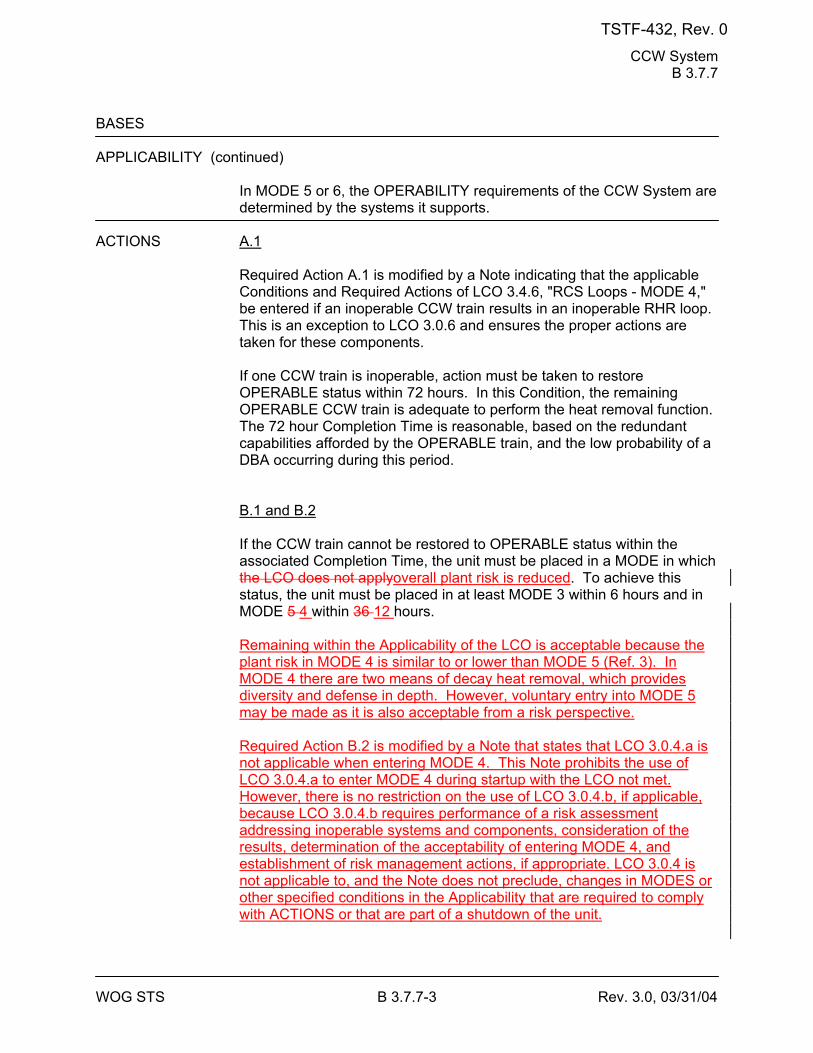
CCW System B 3.7.7
WOG STS B 3.7.7-3 Rev. 3.0, 03/31/04
BASES APPLICABILITY (continued)
In MODE 5 or 6, the OPERABILITY requirements of the CCW System are determined by the systems it supports.
ACTIONS A.1
Required Action A.1 is modified by a Note indicating that the applicable Conditions and Required Actions of LCO 3.4.6, "RCS Loops - MODE 4," be entered if an inoperable CCW train results in an inoperable RHR loop. This is an exception to LCO 3.0.6 and ensures the proper actions are taken for these components. If one CCW train is inoperable, action must be taken to restore OPERABLE status within 72 hours. In this Condition, the remaining OPERABLE CCW train is adequate to perform the heat removal function. The 72 hour Completion Time is reasonable, based on the redundant capabilities afforded by the OPERABLE train, and the low probability of a DBA occurring during this period. B.1 and B.2 If the CCW train cannot be restored to OPERABLE status within the associated Completion Time, the unit must be placed in a MODE in which the LCO does not applyoverall plant risk is reduced. To achieve this status, the unit must be placed in at least MODE 3 within 6 hours and in MODE 5 4 within 36 12 hours. Remaining within the Applicability of the LCO is acceptable because the plant risk in MODE 4 is similar to or lower than MODE 5 (Ref. 3). In MODE 4 there are two means of decay heat removal, which provides diversity and defense in depth. However, voluntary entry into MODE 5 may be made as it is also acceptable from a risk perspective. Required Action B.2 is modified by a Note that states that LCO 3.0.4.a is not applicable when entering MODE 4. This Note prohibits the use of LCO 3.0.4.a to enter MODE 4 during startup with the LCO not met. However, there is no restriction on the use of LCO 3.0.4.b, if applicable, because LCO 3.0.4.b requires performance of a risk assessment addressing inoperable systems and components, consideration of the results, determination of the acceptability of entering MODE 4, and establishment of risk management actions, if appropriate. LCO 3.0.4 is not applicable to, and the Note does not preclude, changes in MODES or other specified conditions in the Applicability that are required to comply with ACTIONS or that are part of a shutdown of the unit.
TSTF-432, Rev. 0
CCW System B 3.7.7
WOG STS B 3.7.7-5 Rev. 3.0, 03/31/04
BASES SURVEILLANCE REQUIREMENTS (continued)
sealing, or securing. This SR also does not apply to valves that cannot be inadvertently misaligned, such as check valves. This Surveillance does not require any testing or valve manipulation; rather, it involves verification that those valves capable of being mispositioned are in the correct position. The 31 day Frequency is based on engineering judgment, is consistent with the procedural controls governing valve operation, and ensures correct valve positions. SR 3.7.7.2 This SR verifies proper automatic operation of the CCW valves on an actual or simulated actuation signal. The CCW System is a normally operating system that cannot be fully actuated as part of routine testing during normal operation. This Surveillance is not required for valves that are locked, sealed, or otherwise secured in the required position under administrative controls. The [18] month Frequency is based on the need to perform this Surveillance under the conditions that apply during a unit outage and the potential for an unplanned transient if the Surveillance were performed with the reactor at power. Operating experience has shown that these components usually pass the Surveillance when performed at the [18] month Frequency. Therefore, the Frequency is acceptable from a reliability standpoint. SR 3.7.7.3 This SR verifies proper automatic operation of the CCW pumps on an actual or simulated actuation signal. The CCW System is a normally operating system that cannot be fully actuated as part of routine testing during normal operation. The [18] month Frequency is based on the need to perform this Surveillance under the conditions that apply during a unit outage and the potential for an unplanned transient if the Surveillance were performed with the reactor at power. Operating experience has shown that these components usually pass the Surveillance when performed at the [18] month Frequency. Therefore, the Frequency is acceptable from a reliability standpoint.
REFERENCES 1. FSAR, Section [9.2.2]. 2. FSAR, Section [6.2].
TSTF-432, Rev. 0
CCW System B 3.7.7
WOG STS B 3.7.7-6 Rev. 3.0, 03/31/04
3. WCAP-16294-NP-A, Rev. 1, "Risk-Informed Evaluation of Changes to Technical Specification Required Action Endstates for Westinghouse NSSS PWRs," [DATE].
TSTF-432, Rev. 0
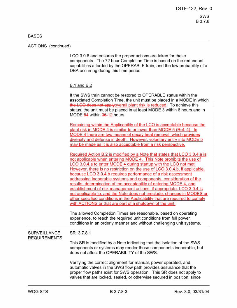
SWS B 3.7.8
WOG STS B 3.7.8-3 Rev. 3.0, 03/31/04
BASES ACTIONS (continued)
LCO 3.0.6 and ensures the proper actions are taken for these components. The 72 hour Completion Time is based on the redundant capabilities afforded by the OPERABLE train, and the low probability of a DBA occurring during this time period. B.1 and B.2 If the SWS train cannot be restored to OPERABLE status within the associated Completion Time, the unit must be placed in a MODE in which the LCO does not applyoverall plant risk is reduced. To achieve this status, the unit must be placed in at least MODE 3 within 6 hours and in MODE 54 within 36 12 hours. Remaining within the Applicability of the LCO is acceptable because the plant risk in MODE 4 is similar to or lower than MODE 5 (Ref. 4). In MODE 4 there are two means of decay heat removal, which provides diversity and defense in depth. However, voluntary entry into MODE 5 may be made as it is also acceptable from a risk perspective. Required Action B.2 is modified by a Note that states that LCO 3.0.4.a is not applicable when entering MODE 4. This Note prohibits the use of LCO 3.0.4.a to enter MODE 4 during startup with the LCO not met. However, there is no restriction on the use of LCO 3.0.4.b, if applicable, because LCO 3.0.4.b requires performance of a risk assessment addressing inoperable systems and components, consideration of the results, determination of the acceptability of entering MODE 4, and establishment of risk management actions, if appropriate. LCO 3.0.4 is not applicable to, and the Note does not preclude, changes in MODES or other specified conditions in the Applicability that are required to comply with ACTIONS or that are part of a shutdown of the unit. The allowed Completion Times are reasonable, based on operating experience, to reach the required unit conditions from full power conditions in an orderly manner and without challenging unit systems.
SURVEILLANCE SR 3.7.8.1 REQUIREMENTS
This SR is modified by a Note indicating that the isolation of the SWS components or systems may render those components inoperable, but does not affect the OPERABILITY of the SWS. Verifying the correct alignment for manual, power operated, and automatic valves in the SWS flow path provides assurance that the proper flow paths exist for SWS operation. This SR does not apply to valves that are locked, sealed, or otherwise secured in position, since
TSTF-432, Rev. 0
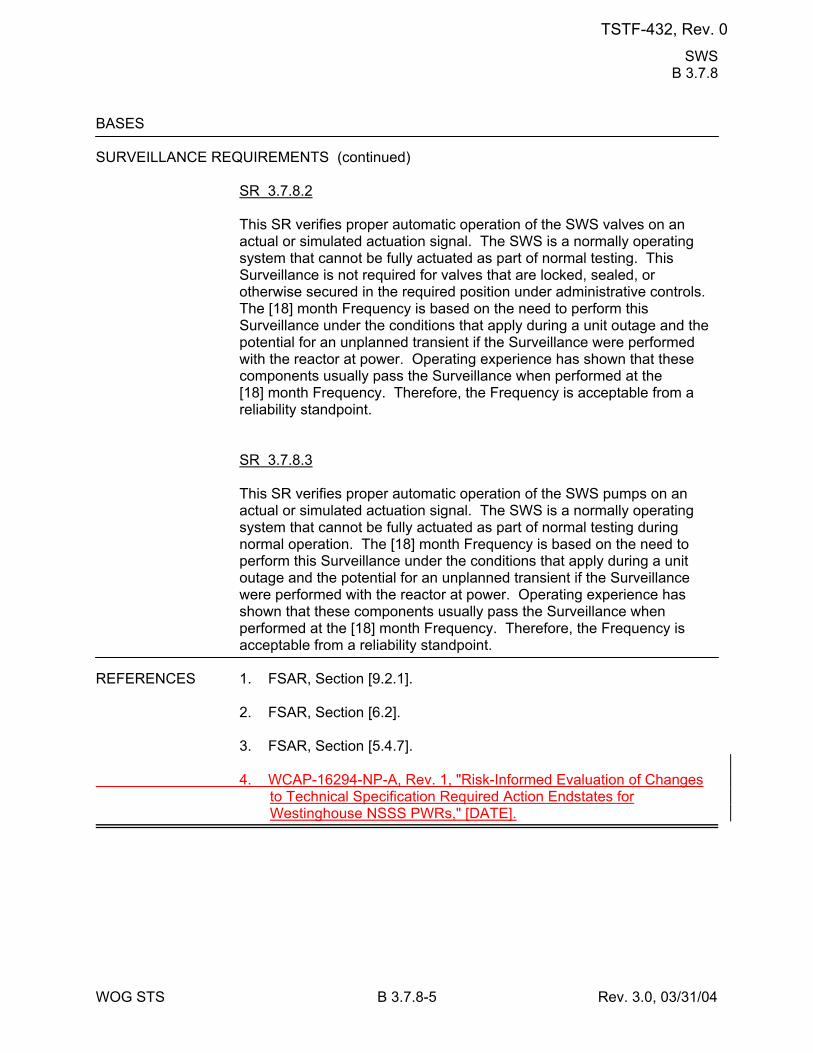
SWS B 3.7.8
WOG STS B 3.7.8-5 Rev. 3.0, 03/31/04
BASES SURVEILLANCE REQUIREMENTS (continued)
SR 3.7.8.2 This SR verifies proper automatic operation of the SWS valves on an actual or simulated actuation signal. The SWS is a normally operating system that cannot be fully actuated as part of normal testing. This Surveillance is not required for valves that are locked, sealed, or otherwise secured in the required position under administrative controls. The [18] month Frequency is based on the need to perform this Surveillance under the conditions that apply during a unit outage and the potential for an unplanned transient if the Surveillance were performed with the reactor at power. Operating experience has shown that these components usually pass the Surveillance when performed at the [18] month Frequency. Therefore, the Frequency is acceptable from a reliability standpoint. SR 3.7.8.3 This SR verifies proper automatic operation of the SWS pumps on an actual or simulated actuation signal. The SWS is a normally operating system that cannot be fully actuated as part of normal testing during normal operation. The [18] month Frequency is based on the need to perform this Surveillance under the conditions that apply during a unit outage and the potential for an unplanned transient if the Surveillance were performed with the reactor at power. Operating experience has shown that these components usually pass the Surveillance when performed at the [18] month Frequency. Therefore, the Frequency is acceptable from a reliability standpoint.
REFERENCES 1. FSAR, Section [9.2.1]. 2. FSAR, Section [6.2]. 3. FSAR, Section [5.4.7]. 4. WCAP-16294-NP-A, Rev. 1, "Risk-Informed Evaluation of Changes
to Technical Specification Required Action Endstates for Westinghouse NSSS PWRs," [DATE].
TSTF-432, Rev. 0
UHS B 3.7.9
WOG STS B 3.7.9-3 Rev. 3.0, 03/31/04
BASES ACTIONS (continued)
The 7 day Completion Time is reasonable based on the low probability of an accident occurring during the 7 days that one cooling tower fan is inoperable (in one or more cooling towers), the number of available systems, and the time required to reasonably complete the Required Action. ]
[ B.1
-----------------------------------REVIEWER’S NOTE----------------------------------- The [ ]°F is the maximum allowed UHS temperature value and is based on temperature limitations of the equipment that is relied upon for accident mitigation and safe shutdown of the unit. -------------------------------------------------------------------------------------------------- With water temperature of the UHS > [90]°F, the design basis assumption associated with initial UHS temperature are bounded provided the temperature of the UHS averaged over the previous 24 hour period is ≤ [90]°F. With the water temperature of the UHS > [90]°F, long term cooling capability of the ECCS loads and DGs may be affected. Therefore, to ensure long term cooling capability is provided to the ECCS loads when water temperature of the UHS is > [90]°F, Required Action B.1 is provided to more frequently monitor the water temperature of the UHS and verify the temperature is ≤ [90]°F when averaged over the previous 24 hour period. The once per hour Completion Time takes into consideration UHS temperature variations and the increased monitoring frequency needed to ensure design basis assumptions and equipment limitations are not exceeded in this condition. If the water temperature of the UHS exceeds [90]°F when averaged over the previous 24 hour period or the water temperature of the UHS exceeds [ ]°F, Condition C must be entered immediately.]
[ C.1 and C.2 If the Required Actions and Completion Times of Condition [A or B] are not met, or the UHS is inoperable for reasons other than Condition A [or B], the unit must be placed in a MODE in which the LCO does not applyoverall plant risk is reduced. To achieve this status, the unit must be placed in at least MODE 3 within 6 hours and in MODE 5 4 within 36 12 hours. Remaining within the Applicability of the LCO is acceptable because the plant risk in MODE 4 is similar to or lower than MODE 5 (Ref. 3). In MODE 4 there are two means of decay heat removal, which provides
TSTF-432, Rev. 0
UHS B 3.7.9
WOG STS B 3.7.9-4 Rev. 3.0, 03/31/04
diversity and defense in depth. However, voluntary entry into MODE 5 may be made as it is also acceptable from a risk perspective. Required Action C.2 is modified by a Note that states that LCO 3.0.4.a is not applicable when entering MODE 4. This Note prohibits the use of LCO 3.0.4.a to enter MODE 4 during startup with the LCO not met. However, there is no restriction on the use of LCO 3.0.4.b, if applicable, because LCO 3.0.4.b requires performance of a risk assessment addressing inoperable systems and components, consideration of the results, determination of the acceptability of entering MODE 4, and establishment of risk management actions, if appropriate. LCO 3.0.4 is not applicable to, and the Note does not preclude, changes in MODES or other specified conditions in the Applicability that are required to comply with ACTIONS or that are part of a shutdown of the unit. The allowed Completion Times are reasonable, based on operating experience, to reach the required unit conditions from full power conditions in an orderly manner and without challenging unit systems. ]
TSTF-432, Rev. 0
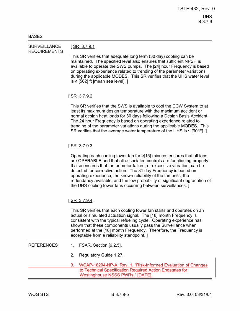
UHS B 3.7.9
WOG STS B 3.7.9-5 Rev. 3.0, 03/31/04
BASES SURVEILLANCE [ SR 3.7.9.1 REQUIREMENTS
This SR verifies that adequate long term (30 day) cooling can be maintained. The specified level also ensures that sufficient NPSH is available to operate the SWS pumps. The [24] hour Frequency is based on operating experience related to trending of the parameter variations during the applicable MODES. This SR verifies that the UHS water level is ≥ [562] ft [mean sea level]. ]
[ SR 3.7.9.2 This SR verifies that the SWS is available to cool the CCW System to at least its maximum design temperature with the maximum accident or normal design heat loads for 30 days following a Design Basis Accident. The 24 hour Frequency is based on operating experience related to trending of the parameter variations during the applicable MODES. This SR verifies that the average water temperature of the UHS is ≤ [90°F]. ]
[ SR 3.7.9.3 Operating each cooling tower fan for ≥[15] minutes ensures that all fans are OPERABLE and that all associated controls are functioning properly. It also ensures that fan or motor failure, or excessive vibration, can be detected for corrective action. The 31 day Frequency is based on operating experience, the known reliability of the fan units, the redundancy available, and the low probability of significant degradation of the UHS cooling tower fans occurring between surveillances. ]
[ SR 3.7.9.4 This SR verifies that each cooling tower fan starts and operates on an actual or simulated actuation signal. The [18] month Frequency is consistent with the typical refueling cycle. Operating experience has shown that these components usually pass the Surveillance when performed at the [18] month Frequency. Therefore, the Frequency is acceptable from a reliability standpoint. ]
REFERENCES 1. FSAR, Section [9.2.5]. 2. Regulatory Guide 1.27. 3. WCAP-16294-NP-A, Rev. 1, "Risk-Informed Evaluation of Changes
to Technical Specification Required Action Endstates for Westinghouse NSSS PWRs," [DATE].
TSTF-432, Rev. 0
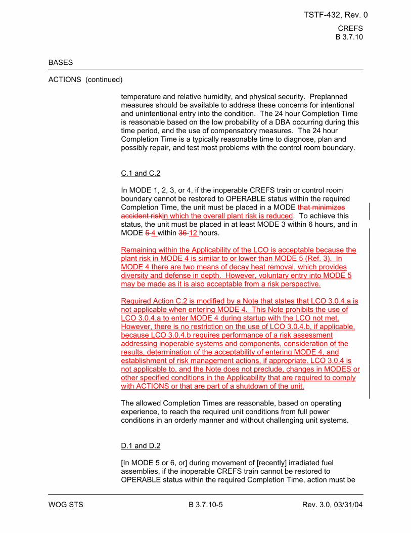
CREFS B 3.7.10
WOG STS B 3.7.10-5 Rev. 3.0, 03/31/04
BASES ACTIONS (continued)
temperature and relative humidity, and physical security. Preplanned measures should be available to address these concerns for intentional and unintentional entry into the condition. The 24 hour Completion Time is reasonable based on the low probability of a DBA occurring during this time period, and the use of compensatory measures. The 24 hour Completion Time is a typically reasonable time to diagnose, plan and possibly repair, and test most problems with the control room boundary. C.1 and C.2 In MODE 1, 2, 3, or 4, if the inoperable CREFS train or control room boundary cannot be restored to OPERABLE status within the required Completion Time, the unit must be placed in a MODE that minimizes accident riskin which the overall plant risk is reduced. To achieve this status, the unit must be placed in at least MODE 3 within 6 hours, and in MODE 5 4 within 36 12 hours. Remaining within the Applicability of the LCO is acceptable because the plant risk in MODE 4 is similar to or lower than MODE 5 (Ref. 3). In MODE 4 there are two means of decay heat removal, which provides diversity and defense in depth. However, voluntary entry into MODE 5 may be made as it is also acceptable from a risk perspective. Required Action C.2 is modified by a Note that states that LCO 3.0.4.a is not applicable when entering MODE 4. This Note prohibits the use of LCO 3.0.4.a to enter MODE 4 during startup with the LCO not met. However, there is no restriction on the use of LCO 3.0.4.b, if applicable, because LCO 3.0.4.b requires performance of a risk assessment addressing inoperable systems and components, consideration of the results, determination of the acceptability of entering MODE 4, and establishment of risk management actions, if appropriate. LCO 3.0.4 is not applicable to, and the Note does not preclude, changes in MODES or other specified conditions in the Applicability that are required to comply with ACTIONS or that are part of a shutdown of the unit. The allowed Completion Times are reasonable, based on operating experience, to reach the required unit conditions from full power conditions in an orderly manner and without challenging unit systems. D.1 and D.2 [In MODE 5 or 6, or] during movement of [recently] irradiated fuel assemblies, if the inoperable CREFS train cannot be restored to OPERABLE status within the required Completion Time, action must be
TSTF-432, Rev. 0
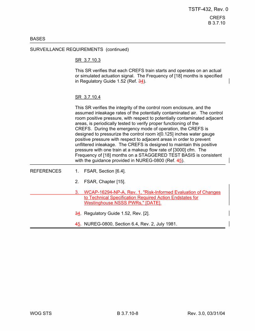
CREFS B 3.7.10
WOG STS B 3.7.10-8 Rev. 3.0, 03/31/04
BASES SURVEILLANCE REQUIREMENTS (continued)
SR 3.7.10.3 This SR verifies that each CREFS train starts and operates on an actual or simulated actuation signal. The Frequency of [18] months is specified in Regulatory Guide 1.52 (Ref. 34). SR 3.7.10.4 This SR verifies the integrity of the control room enclosure, and the assumed inleakage rates of the potentially contaminated air. The control room positive pressure, with respect to potentially contaminated adjacent areas, is periodically tested to verify proper functioning of the CREFS. During the emergency mode of operation, the CREFS is designed to pressurize the control room ≥[0.125] inches water gauge positive pressure with respect to adjacent areas in order to prevent unfiltered inleakage. The CREFS is designed to maintain this positive pressure with one train at a makeup flow rate of [3000] cfm. The Frequency of [18] months on a STAGGERED TEST BASIS is consistent with the guidance provided in NUREG-0800 (Ref. 45).
REFERENCES 1. FSAR, Section [6.4]. 2. FSAR, Chapter [15]. 3. WCAP-16294-NP-A, Rev. 1, "Risk-Informed Evaluation of Changes
to Technical Specification Required Action Endstates for Westinghouse NSSS PWRs," [DATE].
34. Regulatory Guide 1.52, Rev. [2]. 45. NUREG-0800, Section 6.4, Rev. 2, July 1981.
TSTF-432, Rev. 0
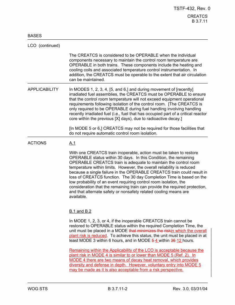
CREATCS B 3.7.11
WOG STS B 3.7.11-2 Rev. 3.0, 03/31/04
BASES LCO (continued)
The CREATCS is considered to be OPERABLE when the individual components necessary to maintain the control room temperature are OPERABLE in both trains. These components include the heating and cooling coils and associated temperature control instrumentation. In addition, the CREATCS must be operable to the extent that air circulation can be maintained.
APPLICABILITY In MODES 1, 2, 3, 4, [5, and 6,] and during movement of [recently]
irradiated fuel assemblies, the CREATCS must be OPERABLE to ensure that the control room temperature will not exceed equipment operational requirements following isolation of the control room. [The CREATCS is only required to be OPERABLE during fuel handling involving handling recently irradiated fuel (i.e., fuel that has occupied part of a critical reactor core within the previous [X] days), due to radioactive decay.]
[In MODE 5 or 6,] CREATCS may not be required for those facilities that do not require automatic control room isolation.
ACTIONS A.1
With one CREATCS train inoperable, action must be taken to restore OPERABLE status within 30 days. In this Condition, the remaining OPERABLE CREATCS train is adequate to maintain the control room temperature within limits. However, the overall reliability is reduced because a single failure in the OPERABLE CREATCS train could result in loss of CREATCS function. The 30 day Completion Time is based on the low probability of an event requiring control room isolation, the consideration that the remaining train can provide the required protection, and that alternate safety or nonsafety related cooling means are available. B.1 and B.2 In MODE 1, 2, 3, or 4, if the inoperable CREATCS train cannot be restored to OPERABLE status within the required Completion Time, the unit must be placed in a MODE that minimizes the riskin which the overall plant risk is reduced. To achieve this status, the unit must be placed in at least MODE 3 within 6 hours, and in MODE 5 4 within 36 12 hours. Remaining within the Applicability of the LCO is acceptable because the plant risk in MODE 4 is similar to or lower than MODE 5 (Ref. 2). In MODE 4 there are two means of decay heat removal, which provides diversity and defense in depth. However, voluntary entry into MODE 5 may be made as it is also acceptable from a risk perspective.
TSTF-432, Rev. 0
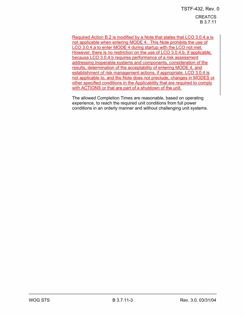
CREATCS B 3.7.11
WOG STS B 3.7.11-3 Rev. 3.0, 03/31/04
Required Action B.2 is modified by a Note that states that LCO 3.0.4.a is not applicable when entering MODE 4. This Note prohibits the use of LCO 3.0.4.a to enter MODE 4 during startup with the LCO not met. However, there is no restriction on the use of LCO 3.0.4.b, if applicable, because LCO 3.0.4.b requires performance of a risk assessment addressing inoperable systems and components, consideration of the results, determination of the acceptability of entering MODE 4, and establishment of risk management actions, if appropriate. LCO 3.0.4 is not applicable to, and the Note does not preclude, changes in MODES or other specified conditions in the Applicability that are required to comply with ACTIONS or that are part of a shutdown of the unit. The allowed Completion Times are reasonable, based on operating experience, to reach the required unit conditions from full power conditions in an orderly manner and without challenging unit systems.
TSTF-432, Rev. 0
CREATCS B 3.7.11
WOG STS B 3.7.11-4 Rev. 3.0, 03/31/04
BASES ACTIONS (continued)
C.1 and C.2 [In MODE 5 or 6, or] during movement of [recently] irradiated fuel, if the inoperable CREATCS train cannot be restored to OPERABLE status within the required Completion Time, the OPERABLE CREATCS train must be placed in operation immediately. This action ensures that the remaining train is OPERABLE, that no failures preventing automatic actuation will occur, and that active failures will be readily detected. An alternative to Required Action C.1 is to immediately suspend activities that present a potential for releasing radioactivity that might require isolation of the control room. This places the unit in a condition that minimizes accident risk. This does not preclude the movement of fuel to a safe position. D.1 [In MODE 5 or 6, or] during movement of [recently] irradiated fuel assemblies, with two CREATCS trains inoperable, action must be taken immediately to suspend activities that could result in a release of radioactivity that might require isolation of the control room. This places the unit in a condition that minimizes risk. This does not preclude the movement of fuel to a safe position. E.1 If both CREATCS trains are inoperable in MODE 1, 2, 3, or 4, the control room CREATCS may not be capable of performing its intended function. Therefore, LCO 3.0.3 must be entered immediately.
SURVEILLANCE SR 3.7.11.1 REQUIREMENTS
This SR verifies that the heat removal capability of the system is sufficient to remove the heat load assumed in the [safety analyses] in the control room. This SR consists of a combination of testing and calculations. The [18] month Frequency is appropriate since significant degradation of the CREATCS is slow and is not expected over this time period.
REFERENCES 1. FSAR, Section [6.4]. 2. WCAP-16294-NP-A, Rev. 1, "Risk-Informed Evaluation of Changes
to Technical Specification Required Action Endstates for Westinghouse NSSS PWRs," [DATE].
TSTF-432, Rev. 0
ECCS PREACS B 3.7.12
WOG STS B 3.7.12-4 Rev. 3.0, 03/31/04
BASES ACTIONS (continued)
If the ECCS pump room boundary is inoperable, the ECCS PREACS trains cannot perform their intended functions. Actions must be taken to restore an OPERABLE ECCS pump room boundary within 24 hours. During the period that the ECCS pump room boundary is inoperable, appropriate compensatory measures [consistent with the intent, as applicable, of GDC 19, 60, 64 and 10 CFR Part 100] should be utilized to protect plant personnel from potential hazards such as radioactive contamination, toxic chemicals, smoke, temperature and relative humidity, and physical security. Preplanned measures should be available to address these concerns for intentional and unintentional entry into the condition. The 24 hour Completion Time is reasonable based on the low probability of a DBA occurring during this time period, and the use of compensatory measures. The 24 hour Completion Time is a typically reasonable time to diagnose, plan and possibly repair, and test most problems with the ECCS pump room boundary. C.1 and C.2 If the ECCS PREACS train or ECCS pump room boundary cannot be restored to OPERABLE status within the associated Completion Time, the unit must be placed in a MODE in which the LCO does not applyoverall plant risk is reduced. To achieve this status, the unit must be placed in at least MODE 3 within 6 hours, and in MODE 5 4 within 36 12 hours. Remaining within the Applicability of the LCO is acceptable because the plant risk in MODE 4 is similar to or lower than MODE 5 (Ref. 6). In MODE 4 there are two means of decay heat removal, which provides diversity and defense in depth. However, voluntary entry into MODE 5 may be made as it is also acceptable from a risk perspective. Required Action C.2 is modified by a Note that states that LCO 3.0.4.a is not applicable when entering MODE 4. This Note prohibits the use of LCO 3.0.4.a to enter MODE 4 during startup with the LCO not met. However, there is no restriction on the use of LCO 3.0.4.b, if applicable, because LCO 3.0.4.b requires performance of a risk assessment addressing inoperable systems and components, consideration of the results, determination of the acceptability of entering MODE 4, and establishment of risk management actions, if appropriate. LCO 3.0.4 is not applicable to, and the Note does not preclude, changes in MODES or other specified conditions in the Applicability that are required to comply with ACTIONS or that are part of a shutdown of the unit.
TSTF-432, Rev. 0
ECCS PREACS B 3.7.12
WOG STS B 3.7.12-6 Rev. 3.0, 03/31/04
BASES SURVEILLANCE REQUIREMENTS (continued)
SR 3.7.12.2 This SR verifies that the required ECCS PREACS testing is performed in accordance with the [Ventilation Filter Testing Program (VFTP)]. The [VFTP] includes testing HEPA filter performance, charcoal adsorbers efficiency, minimum system flow rate, and the physical properties of the activated charcoal (general use and following specific operations). Specific test Frequencies and additional information are discussed in detail in the [VFTP]. SR 3.7.12.3 This SR verifies that each ECCS PREACS train starts and operates on an actual or simulated actuation signal. The [18] month Frequency is consistent with that specified in Reference 4. SR 3.7.12.4 This SR verifies the integrity of the ECCS pump room enclosure. The ability of the ECCS pump room to maintain a negative pressure, with respect to potentially uncontaminated adjacent areas, is periodically tested to verify proper functioning of the ECCS PREACS. During the [post accident] mode of operation, the ECCS PREACS is designed to maintain a slight negative pressure in the ECCS pump room, with respect to adjacent areas, to prevent unfiltered LEAKAGE. The ECCS PREACS is designed to maintain a ≤[-0.125] inches water gauge relative to atmospheric pressure at a flow rate of [3000] cfm from the ECCS pump room. The Frequency of [18] months is consistent with the guidance provided in NUREG-0800, Section 6.5.1 (Ref. 67). This test is conducted with the tests for filter penetration; thus, an [18] month Frequency on a STAGGERED TEST BASIS is consistent with that specified in Reference 4.
[ SR 3.7.12.5 Operating the ECCS PREACS bypass damper is necessary to ensure that the system functions properly. The OPERABILITY of the ECCS PREACS bypass damper is verified if it can be specified in Reference 4. ]
TSTF-432, Rev. 0
ECCS PREACS B 3.7.12
WOG STS B 3.7.12-7 Rev. 3.0, 03/31/04
BASES REFERENCES 1. FSAR, Section [6.5.1]. 2. FSAR, Section [9.4.5]. 3. FSAR, Section [15.6.5]. 4. Regulatory Guide 1.52 (Rev. 2). 5. 10 CFR 100.11. 6. WCAP-16294-NP-A, Rev. 1, "Risk-Informed Evaluation of Changes
to Technical Specification Required Action Endstates for Westinghouse NSSS PWRs," [DATE].
67. NUREG-0800, Section 6.5.1, Rev. 2, July 1981.
TSTF-432, Rev. 0
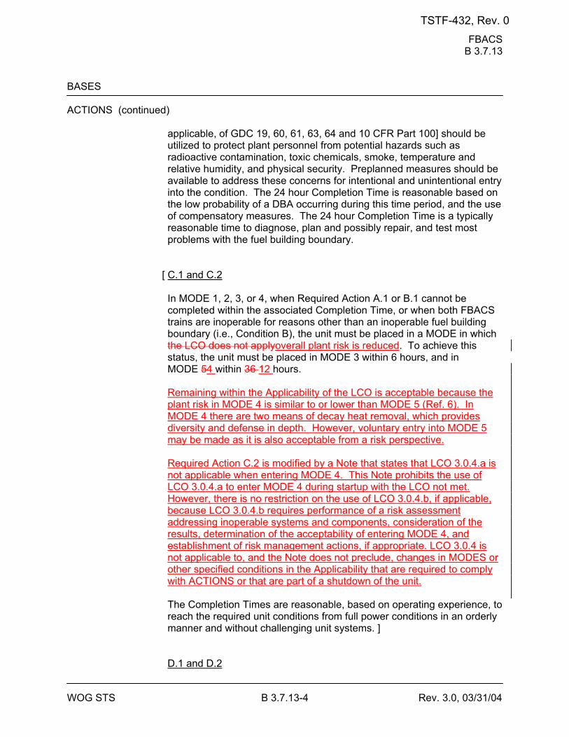
FBACS B 3.7.13
WOG STS B 3.7.13-4 Rev. 3.0, 03/31/04
BASES ACTIONS (continued)
applicable, of GDC 19, 60, 61, 63, 64 and 10 CFR Part 100] should be utilized to protect plant personnel from potential hazards such as radioactive contamination, toxic chemicals, smoke, temperature and relative humidity, and physical security. Preplanned measures should be available to address these concerns for intentional and unintentional entry into the condition. The 24 hour Completion Time is reasonable based on the low probability of a DBA occurring during this time period, and the use of compensatory measures. The 24 hour Completion Time is a typically reasonable time to diagnose, plan and possibly repair, and test most problems with the fuel building boundary.
[ C.1 and C.2 In MODE 1, 2, 3, or 4, when Required Action A.1 or B.1 cannot be completed within the associated Completion Time, or when both FBACS trains are inoperable for reasons other than an inoperable fuel building boundary (i.e., Condition B), the unit must be placed in a MODE in which the LCO does not applyoverall plant risk is reduced. To achieve this status, the unit must be placed in MODE 3 within 6 hours, and in MODE 54 within 36 12 hours. Remaining within the Applicability of the LCO is acceptable because the plant risk in MODE 4 is similar to or lower than MODE 5 (Ref. 6). In MODE 4 there are two means of decay heat removal, which provides diversity and defense in depth. However, voluntary entry into MODE 5 may be made as it is also acceptable from a risk perspective. Required Action C.2 is modified by a Note that states that LCO 3.0.4.a is not applicable when entering MODE 4. This Note prohibits the use of LCO 3.0.4.a to enter MODE 4 during startup with the LCO not met. However, there is no restriction on the use of LCO 3.0.4.b, if applicable, because LCO 3.0.4.b requires performance of a risk assessment addressing inoperable systems and components, consideration of the results, determination of the acceptability of entering MODE 4, and establishment of risk management actions, if appropriate. LCO 3.0.4 is not applicable to, and the Note does not preclude, changes in MODES or other specified conditions in the Applicability that are required to comply with ACTIONS or that are part of a shutdown of the unit. The Completion Times are reasonable, based on operating experience, to reach the required unit conditions from full power conditions in an orderly manner and without challenging unit systems. ] D.1 and D.2
TSTF-432, Rev. 0
FBACS B 3.7.13
WOG STS B 3.7.13-6 Rev. 3.0, 03/31/04
BASES ACTIONS (continued)
E.1 When two trains of the FBACS are inoperable during movement of [recently] irradiated fuel assemblies in the fuel building, action must be taken to place the unit in a condition in which the LCO does not apply. Action must be taken immediately to suspend movement of [recently] irradiated fuel assemblies in the fuel building. This does not preclude the movement of fuel to a safe position.
SURVEILLANCE SR 3.7.13.1 REQUIREMENTS
Standby systems should be checked periodically to ensure that they function properly. As the environmental and normal operating conditions on this system are not severe, testing each train once every month provides an adequate check on this system. Monthly heater operation dries out any moisture accumulated in the charcoal from humidity in the ambient air. [Systems with heaters must be operated for ≥10 continuous hours with the heaters energized. Systems without heaters need only be operated for ≥15 minutes to demonstrate the function of the system.] The 31 day Frequency is based on the known reliability of the equipment and the two train redundancy available. [ SR 3.7.13.2 This SR verifies that the required FBACS testing is performed in accordance with the [Ventilation Filter Testing Program (VFTP)]. The [VFTP] includes testing HEPA filter performance, charcoal adsorber efficiency, minimum system flow rate, and the physical properties of the activated charcoal (general use and following specific operations). Specific test frequencies and additional information are discussed in detail in the [VFTP]. ]
[ SR 3.7.13.3 This SR verifies that each FBACS train starts and operates on an actual or simulated actuation signal. The [18] month Frequency is consistent with Reference 67. ]
TSTF-432, Rev. 0
FBACS B 3.7.13
WOG STS B 3.7.13-7 Rev. 3.0, 03/31/04
BASES SURVEILLANCE REQUIREMENTS (continued)
SR 3.7.13.4 This SR verifies the integrity of the fuel building enclosure. The ability of the fuel building to maintain negative pressure with respect to potentially uncontaminated adjacent areas is periodically tested to verify proper function of the FBACS. During the [post accident] mode of operation, the FBACS is designed to maintain a slight negative pressure in the fuel building, to prevent unfiltered LEAKAGE. The FBACS is designed to maintain a ≤[-0.125] inches water gauge with respect to atmospheric pressure at a flow rate of [20,000] cfm to the fuel building. The Frequency of [18] months is consistent with the guidance provided in NUREG-0800, Section 6.5.1 (Ref. 78). An [18] month Frequency (on a STAGGERED TEST BASIS) is consistent with Reference 67.
[ SR 3.7.13.5 Operating the FBACS filter bypass damper is necessary to ensure that the system functions properly. The OPERABILITY of the FBACS filter bypass damper is verified if it can be closed. An [18] month Frequency is consistent with Reference 67. ]
REFERENCES 1. FSAR, Section [6.5.1]. 2. FSAR, Section [9.4.5]. 3. FSAR, Section [15.7.4]. 4. Regulatory Guide 1.25. 5. 10 CFR 100. 6. WCAP-16294-NP-A, Rev. 1, "Risk-Informed Evaluation of Changes
to Technical Specification Required Action Endstates for Westinghouse NSSS PWRs," [DATE].
67. Regulatory Guide 1.52, Rev. [2]. 78. NUREG-0800, Section 6.5.1, Rev. 2, July 1981.
TSTF-432, Rev. 0
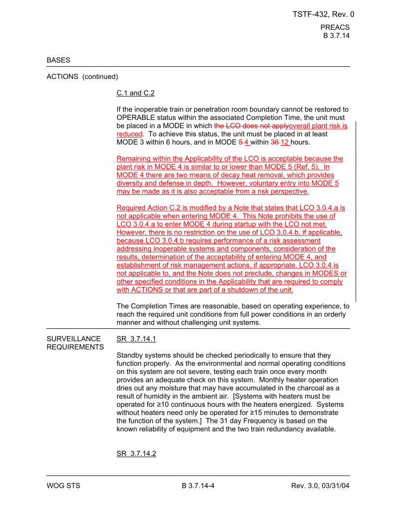
PREACS B 3.7.14
WOG STS B 3.7.14-4 Rev. 3.0, 03/31/04
BASES ACTIONS (continued)
C.1 and C.2 If the inoperable train or penetration room boundary cannot be restored to OPERABLE status within the associated Completion Time, the unit must be placed in a MODE in which the LCO does not applyoverall plant risk is reduced. To achieve this status, the unit must be placed in at least MODE 3 within 6 hours, and in MODE 5 4 within 36 12 hours. Remaining within the Applicability of the LCO is acceptable because the plant risk in MODE 4 is similar to or lower than MODE 5 (Ref. 5). In MODE 4 there are two means of decay heat removal, which provides diversity and defense in depth. However, voluntary entry into MODE 5 may be made as it is also acceptable from a risk perspective. Required Action C.2 is modified by a Note that states that LCO 3.0.4.a is not applicable when entering MODE 4. This Note prohibits the use of LCO 3.0.4.a to enter MODE 4 during startup with the LCO not met. However, there is no restriction on the use of LCO 3.0.4.b, if applicable, because LCO 3.0.4.b requires performance of a risk assessment addressing inoperable systems and components, consideration of the results, determination of the acceptability of entering MODE 4, and establishment of risk management actions, if appropriate. LCO 3.0.4 is not applicable to, and the Note does not preclude, changes in MODES or other specified conditions in the Applicability that are required to comply with ACTIONS or that are part of a shutdown of the unit. The Completion Times are reasonable, based on operating experience, to reach the required unit conditions from full power conditions in an orderly manner and without challenging unit systems.
SURVEILLANCE SR 3.7.14.1 REQUIREMENTS
Standby systems should be checked periodically to ensure that they function properly. As the environmental and normal operating conditions on this system are not severe, testing each train once every month provides an adequate check on this system. Monthly heater operation dries out any moisture that may have accumulated in the charcoal as a result of humidity in the ambient air. [Systems with heaters must be operated for ≥10 continuous hours with the heaters energized. Systems without heaters need only be operated for ≥15 minutes to demonstrate the function of the system.] The 31 day Frequency is based on the known reliability of equipment and the two train redundancy available. SR 3.7.14.2
TSTF-432, Rev. 0
PREACS B 3.7.14
WOG STS B 3.7.14-5 Rev. 3.0, 03/31/04
This SR verifies that the required PREACS testing is performed in accordance with the [Ventilation Filter Testing Program (VFTP)]. The [VFTP] includes testing HEPA filter performance, charcoal adsorber efficiency, minimum system flow rate, and the physical properties of the activated charcoal (general use and following specific operations). Specific test frequencies and additional information are discussed in detail in the [VFTP].
[ SR 3.7.14.3 This SR verifies that each PREACS starts and operates on an actual or simulated actuation signal. The [18] month Frequency is consistent with that specified in Reference 56. ]
TSTF-432, Rev. 0
PREACS B 3.7.14
WOG STS B 3.7.14-6 Rev. 3.0, 03/31/04
BASES SURVEILLANCE REQUIREMENTS (continued)
[ SR 3.7.14.4 This SR verifies the integrity of the penetration room enclosure. The ability of the penetration room to maintain a negative pressure, with respect to potentially uncontaminated adjacent areas, is periodically tested to verify proper function of PREACS. During the [post accident] mode of operation, the PREACS is designed to maintain a ≤[-0.125] inches water gauge relative to atmospheric pressure at a flow rate of [3000] cfm in the penetration room, with respect to adjacent areas, to prevent unfiltered LEAKAGE. The Frequency of [18] months is consistent with the guidance provided in NUREG-0800 (Ref. 67). The minimum system flow rate maintains a slight negative pressure in the penetration room area, and provides sufficient air velocity to transport particulate contaminants, assuming only one filter train is operating. The number of filter elements is selected to limit the flow rate through any individual element to about [3000] cfm. This may vary based on filter housing geometry. The maximum limit ensures that the flow through, and pressure drop across, each filter element are not excessive. The number and depth of the adsorber elements ensure that, at the maximum flow rate, the residence time of the air stream in the charcoal bed achieves the desired adsorption rate. At least a [0.125] second residence time is necessary for an assumed [99]% efficiency. The filters have a certain pressure drop at the design flow rate when clean. The magnitude of the pressure drop indicates acceptable performance, and is based on manufacturers' recommendations for the filter and adsorber elements at the design flow rate. An increase in pressure drop or a decrease in flow indicates that the filter is being loaded or that there are other problems with the system. This test is conducted along with the tests for filter penetration; thus, the [18] month Frequency is consistent with that specified in Reference 56. ]
[ SR 3.7.14.5 It is necessary to operate the PREACS filter bypass damper to ensure that the system functions properly. The OPERABILITY of the PREACS filter bypass damper is verified if it can be closed. An [18] month Frequency is consistent with that specified in Reference 56. ]
TSTF-432, Rev. 0
PREACS B 3.7.14
WOG STS B 3.7.14-7 Rev. 3.0, 03/31/04
BASES REFERENCES 1. FSAR, Section [6.5.1]. 2. FSAR, Section [9.4.5]. 3. FSAR, Section [15.6.5]. 4. 10 CFR 100. 5. WCAP-16294-NP-A, Rev. 1, "Risk-Informed Evaluation of Changes
to Technical Specification Required Action Endstates for Westinghouse NSSS PWRs," [DATE].
56. Regulatory Guide 1.52, Rev. [2]. 67. NUREG-0800, Section 6.5.1, Rev. 2, July 1981.
TSTF-432, Rev. 0
WOG STS B 3.8.1-12 Rev. 3.1, 12/01/05
BASES ACTIONS (continued)
G.1 and G.2 If the inoperable AC electric power sources cannot be restored to OPERABLE status within the required Completion Time, the unit must be brought to a MODE in which the LCO does not applyoverall plant risk is reduced. To achieve this status, the unit must be brought to at least MODE 3 within 6 hours and to MODE 5 4 within 36 12 hours. Remaining within the Applicability of the LCO is acceptable because the plant risk in MODE 4 is similar to or lower than MODE 5 (Ref. 8). In MODE 4 there are two means of decay heat removal, which provides diversity and defense in depth. However, voluntary entry into MODE 5 may be made as it is also acceptable from a risk perspective. Required Action G.2 is modified by a Note that states that LCO 3.0.4.a is not applicable when entering MODE 4. This Note prohibits the use of LCO 3.0.4.a to enter MODE 4 during startup with the LCO not met. However, there is no restriction on the use of LCO 3.0.4.b, if applicable, because LCO 3.0.4.b requires performance of a risk assessment addressing inoperable systems and components, consideration of the results, determination of the acceptability of entering MODE 4, and establishment of risk management actions, if appropriate. LCO 3.0.4 is not applicable to, and the Note does not preclude, changes in MODES or other specified conditions in the Applicability that are required to comply with ACTIONS or that are part of a shutdown of the unit. The allowed Completion Times are reasonable, based on operating experience, to reach the required unit conditions from full power conditions in an orderly manner and without challenging plant systems. H.1 Condition H corresponds to a level of degradation in which all redundancy in the AC electrical power supplies has been lost. At this severely degraded level, any further losses in the AC electrical power system will cause a loss of function. Therefore, no additional time is justified for continued operation. The unit is required by LCO 3.0.3 to commence a controlled shutdown.
SURVEILLANCE The AC sources are designed to permit inspection and testing of all REQUIREMENTS important areas and features, especially those that have a standby
function, in accordance with 10 CFR 50, Appendix A, GDC 18 (Ref. 89). Periodic component tests are supplemented by extensive functional tests during refueling outages (under simulated accident conditions). The SRs for demonstrating the OPERABILITY of the DGs are in accordance with the recommendations of Regulatory Guide 1.9 (Ref. 3), Regulatory Guide 1.108 (Ref. 910), and Regulatory Guide 1.137 (Ref. 1011), as addressed in the FSAR.
TSTF-432, Rev. 0
WOG STS B 3.8.1-13 Rev. 3.1, 12/01/05
Where the SRs discussed herein specify voltage and frequency tolerances, the following is applicable. The minimum steady state output voltage of [3740] V is 90% of the nominal 4160 V output voltage. This value, which is specified in ANSI C84.1 (Ref. 1112), allows for voltage drop to the terminals of 4000 V motors whose minimum operating voltage is specified as 90% or 3600 V. It also allows for voltage drops to motors and other equipment down through the 120 V level where minimum operating voltage is also usually specified as 90% of name plate rating. The specified maximum steady state output voltage of [4756] V is equal to the maximum operating voltage specified for 4000 V motors. It ensures that for a lightly loaded distribution system, the voltage at the terminals of 4000 V motors is no more than the maximum rated operating
TSTF-432, Rev. 0
WOG STS B 3.8.1-16 Rev. 3.1, 12/01/05
BASES SURVEILLANCE REQUIREMENTS (continued)
This SR is modified by four Notes. Note 1 indicates that diesel engine runs for this Surveillance may include gradual loading, as recommended by the manufacturer, so that mechanical stress and wear on the diesel engine are minimized. Note 2 states that momentary transients, because of changing bus loads, do not invalidate this test. Similarly, momentary power factor transients above the limit do not invalidate the test. Note 3 indicates that this Surveillance should be conducted on only one DG at a time in order to avoid common cause failures that might result from offsite circuit or grid perturbations. Note 4 stipulates a prerequisite requirement for performance of this SR. A successful DG start must precede this test to credit satisfactory performance. SR 3.8.1.4 This SR provides verification that the level of fuel oil in the day tank [and engine mounted tank] is at or above the level at which fuel oil is automatically added. The level is expressed as an equivalent volume in gallons, and is selected to ensure adequate fuel oil for a minimum of 1 hour of DG operation at full load plus 10%. The 31 day Frequency is adequate to assure that a sufficient supply of fuel oil is available, since low level alarms are provided and facility operators would be aware of any large uses of fuel oil during this period. SR 3.8.1.5 Microbiological fouling is a major cause of fuel oil degradation. There are numerous bacteria that can grow in fuel oil and cause fouling, but all must have a water environment in order to survive. Removal of water from the fuel oil day [and engine mounted] tanks once every [31] days eliminates the necessary environment for bacterial survival. This is the most effective means of controlling microbiological fouling. In addition, it eliminates the potential for water entrainment in the fuel oil during DG operation. Water may come from any of several sources, including condensation, ground water, rain water, contaminated fuel oil, and breakdown of the fuel oil by bacteria. Frequent checking for and removal of accumulated water minimizes fouling and provides data regarding the watertight integrity of the fuel oil system. The Surveillance Frequencies are established by Regulatory Guide 1.137 (Ref. 1011). This SR is for preventative maintenance. The presence of water does not necessarily represent failure of this SR, provided the accumulated water is removed during the performance of this Surveillance.
TSTF-432, Rev. 0
WOG STS B 3.8.1-17 Rev. 3.1, 12/01/05
BASES SURVEILLANCE REQUIREMENTS (continued)
SR 3.8.1.6 This Surveillance demonstrates that each required fuel oil transfer pump operates and transfers fuel oil from its associated storage tank to its associated day tank. This is required to support continuous operation of standby power sources. This Surveillance provides assurance that the fuel oil transfer pump is OPERABLE, the fuel oil piping system is intact, the fuel delivery piping is not obstructed, and the controls and control systems for automatic fuel transfer systems are OPERABLE.
[ The Frequency for this SR is variable, depending on individual system design, with up to a [92] day interval. The [92] day Frequency corresponds to the testing requirements for pumps as contained in the ASME Code (Ref. 1112); however, the design of fuel transfer systems is such that pumps operate automatically or must be started manually in order to maintain an adequate volume of fuel oil in the day [and engine mounted] tanks during or following DG testing. In such a case, a 31 day Frequency is appropriate. Since proper operation of fuel transfer systems is an inherent part of DG OPERABILITY, the Frequency of this SR should be modified to reflect individual designs. ] SR 3.8.1.7 See SR 3.8.1.2.
[ SR 3.8.1.8 Transfer of each [4.16 kV ESF bus] power supply from the normal offsite circuit to the alternate offsite circuit demonstrates the OPERABILITY of the alternate circuit distribution network to power the shutdown loads. The [18 month] Frequency of the Surveillance is based on engineering judgment, taking into consideration the unit conditions required to perform the Surveillance, and is intended to be consistent with expected fuel cycle lengths. Operating experience has shown that these components usually pass the SR when performed at the [18 month] Frequency. Therefore, the Frequency was concluded to be acceptable from a reliability standpoint. This SR is modified by a Note. The reason for the Note is that, during operation with the reactor critical, performance of this SR could cause perturbations to the electrical distribution systems that could challenge continued steady state operation and, as a result, unit safety systems. This restriction from normally performing the Surveillance in MODE 1 or 2
TSTF-432, Rev. 0
WOG STS B 3.8.1-18 Rev. 3.1, 12/01/05
BASES SURVEILLANCE REQUIREMENTS (continued)
is further amplified to allow the Surveillance to be performed for the purpose of reestablishing OPERABILITY (e.g., post work testing following corrective maintenance, corrective modification, deficient or incomplete surveillance testing, and other unanticipated OPERABILITY concerns) provided an assessment determines plant safety is maintained or enhanced. This assessment shall, as a minimum, consider the potential outcomes and transients associated with a failed Surveillance, a successful Surveillance, and a perturbation of the offsite or onsite system when they are tied together or operated independently for the Surveillance; as well as the operator procedures available to cope with these outcomes. These shall be measured against the avoided risk of a plant shutdown and startup to determine that plant safety is maintained or enhanced when the Surveillance is performed in MODE 1 or 2. Risk insights or deterministic methods may be used for this assessment.] Credit may be taken for unplanned events that satisfy this SR. SR 3.8.1.9 Each DG is provided with an engine overspeed trip to prevent damage to the engine. Recovery from the transient caused by the loss of a large load could cause diesel engine overspeed, which, if excessive, might result in a trip of the engine. This Surveillance demonstrates the DG load response characteristics and capability to reject the largest single load without exceeding predetermined voltage and frequency and while maintaining a specified margin to the overspeed trip. [For this unit, the single load for each DG and its horsepower rating is as follows:] This Surveillance may be accomplished by: a. Tripping the DG output breaker with the DG carrying greater than or
equal to its associated single largest post-accident load while paralleled to offsite power, or while solely supplying the bus, or
b. Tripping its associated single largest post-accident load with the DG
solely supplying the bus. As required by IEEE-308 (Ref. 1213), the load rejection test is acceptable if the increase in diesel speed does not exceed 75% of the difference between synchronous speed and the overspeed trip setpoint, or 15% above synchronous speed, whichever is lower. The time, voltage, and frequency tolerances specified in this SR are derived from Regulatory Guide 1.9 (Ref. 3) recommendations for response during load sequence intervals. The 3 seconds specified is equal to 60% of a typical 5 second load sequence interval associated with
TSTF-432, Rev. 0
WOG STS B 3.8.1-19 Rev. 3.1, 12/01/05
BASES SURVEILLANCE REQUIREMENTS (continued)
sequencing of the largest load. The voltage and frequency specified are consistent with the design range of the equipment powered by the DG. SR 3.8.1.9.a corresponds to the maximum frequency excursion, while SR 3.8.1.9.b and SR 3.8.1.9.c are steady state voltage and frequency values to which the system must recover following load rejection. The [18 month] Frequency is consistent with the recommendation of Regulatory Guide 1.108 (Ref. 910). This SR is modified by two Notes. The reason for Note 1 is that during operation with the reactor critical, performance of this SR could cause perturbations to the electrical distribution systems that could challenge continued steady state operation and, as a result, unit safety systems. This restriction from normally performing the Surveillance in MODE 1 or 2 is further amplified to allow the Surveillance to be performed for the purpose of reestablishing OPERABILITY (e.g., post work testing following corrective maintenance, corrective modification, deficient or incomplete surveillance testing, and other unanticipated OPERABILITY concerns) provided an assessment determines plant safety is maintained or enhanced. This assessment shall, as a minimum, consider the potential outcomes and transients associated with a failed Surveillance, a successful Surveillance, and a perturbation of the offsite or onsite system when they are tied together or operated independently for the Surveillance; as well as the operator procedures available to cope with these outcomes. These shall be measured against the avoided risk of a plant shutdown and startup to determine that plant safety is maintained or enhanced when the Surveillance is performed in MODE 1 or 2. Risk insights or deterministic methods may be used for this assessment. Credit may be taken for unplanned events that satisfy this SR. Note 2 ensures that the DG is tested under load conditions that are as close to design basis conditions as possible. When synchronized with offsite power, testing should be performed at a power factor of ≤ [0.9]. This power factor is representative of the actual inductive loading a DG would see under design basis accident conditions. Under certain conditions, however, Note 2 allows the Surveillance to be conducted at a power factor other than ≤ [0.9]. These conditions occur when grid voltage is high, and the additional field excitation needed to get the power factor to ≤ [0.9] results in voltages on the emergency busses that are too high. Under these conditions, the power factor should be maintained as close as practicable to [0.9] while still maintaining acceptable voltage limits on the emergency busses. In other circumstances, the grid voltage may be such that the DG excitation levels needed to obtain a power factor of [0.9] may not cause unacceptable voltages on the emergency busses, but the excitation levels are in excess of those recommended for the DG. In such cases, the power factor shall be maintained as close as practicable to [0.9] without exceeding the DG excitation limits.
TSTF-432, Rev. 0
WOG STS B 3.8.1-20 Rev. 3.1, 12/01/05
BASES SURVEILLANCE REQUIREMENTS (continued)
-----------------------------------REVIEWER’S NOTE----------------------------------- The above MODE restrictions may be deleted if it can be demonstrated to the staff, on a plant specific basis, that performing the SR with the reactor in any of the restricted MODES can satisfy the following criteria, as applicable: a. Performance of the SR will not render any safety system or
component inoperable, b. Performance of the SR will not cause perturbations to any of the
electrical distribution systems that could result in a challenge to steady state operation or to plant safety systems, and
c. Performance of the SR, or failure of the SR, will not cause, or result
in, an AOO with attendant challenge to plant safety systems. -------------------------------------------------------------------------------------------------- SR 3.8.1.10 This Surveillance demonstrates the DG capability to reject a full load without overspeed tripping or exceeding the predetermined voltage limits. The DG full load rejection may occur because of a system fault or inadvertent breaker tripping. This Surveillance ensures proper engine generator load response under the simulated test conditions. This test simulates the loss of the total connected load that the DG experiences following a full load rejection and verifies that the DG does not trip upon loss of the load. These acceptance criteria provide for DG damage protection. While the DG is not expected to experience this transient during an event and continues to be available, this response ensures that the DG is not degraded for future application, including reconnection to the bus if the trip initiator can be corrected or isolated. The [18 month] Frequency is consistent with the recommendation of Regulatory Guide 1.108 (Ref. 910) and is intended to be consistent with expected fuel cycle lengths. This SR has been modified by two Notes. The reason for Note 1 is that during operation with the reactor critical, performance of this SR could cause perturbation to the electrical distribution systems that could challenge continued steady state operation and, as a result, unit safety
TSTF-432, Rev. 0
WOG STS B 3.8.1-22 Rev. 3.1, 12/01/05
BASES SURVEILLANCE REQUIREMENTS (continued)
a. Performance of the SR will not render any safety system or
component inoperable, b. Performance of the SR will not cause perturbations to any of the
electrical distribution systems that could result in a challenge to steady state operation or to plant safety systems, and
c. Performance of the SR, or failure of the SR, will not cause, or result
in, an AOO with attendant challenge to plant safety systems. -------------------------------------------------------------------------------------------------- SR 3.8.1.11 As required by Regulatory Guide 1.108 (Ref. 910), paragraph 2.a.(1), this Surveillance demonstrates the as designed operation of the standby power sources during loss of the offsite source. This test verifies all actions encountered from the loss of offsite power, including shedding of the nonessential loads and energization of the emergency buses and respective loads from the DG. It further demonstrates the capability of the DG to automatically achieve the required voltage and frequency within the specified time. The DG autostart time of [10] seconds is derived from requirements of the accident analysis to respond to a design basis large break LOCA. The Surveillance should be continued for a minimum of 5 minutes in order to demonstrate that all starting transients have decayed and stability is achieved. The requirement to verify the connection and power supply of permanent and autoconnected loads is intended to satisfactorily show the relationship of these loads to the DG loading logic. In certain circumstances, many of these loads cannot actually be connected or loaded without undue hardship or potential for undesired operation. For instance, Emergency Core Cooling Systems (ECCS) injection valves are not desired to be stroked open, or high pressure injection systems are not capable of being operated at full flow, or residual heat removal (RHR) systems performing a decay heat removal function are not desired to be realigned to the ECCS mode of operation. In lieu of actual demonstration of connection and loading of loads, testing that adequately shows the capability of the DG systems to perform these functions is acceptable. This testing may include any series of sequential, overlapping, or total steps so that the entire connection and loading sequence is verified.
TSTF-432, Rev. 0
WOG STS B 3.8.1-23 Rev. 3.1, 12/01/05
BASES SURVEILLANCE REQUIREMENTS (continued)
The Frequency of [18 months] is consistent with the recommendations of Regulatory Guide 1.108 (Ref. 910), paragraph 2.a.(1), takes into consideration unit conditions required to perform the Surveillance, and is intended to be consistent with expected fuel cycle lengths. This SR is modified by two Notes. The reason for Note 1 is to minimize wear and tear on the DGs during testing. For the purpose of this testing, the DGs must be started from standby conditions, that is, with the engine coolant and oil continuously circulated and temperature maintained consistent with manufacturer recommendations. The reason for Note 2 is that performing the Surveillance would remove a required offsite circuit from service, perturb the electrical distribution system, and challenge safety systems. This restriction from normally performing the Surveillance in MODE 1 or 2 is further amplified to allow portions of the Surveillance to be performed for the purpose of reestablishing OPERABILITY (e.g., post work testing following corrective maintenance, corrective modification, deficient or incomplete surveillance testing, and other unanticipated OPERABILITY concerns) provided an assessment determines plant safety is maintained or enhanced. This assessment shall, as a minimum, consider the potential outcomes and transients associated with a failed partial Surveillance, a successful partial Surveillance, and a perturbation of the offsite or onsite system when they are tied together or operated independently for the partial Surveillance; as well as the operator procedures available to cope with these outcomes. These shall be measured against the avoided risk of a plant shutdown and startup to determine that plant safety is maintained or enhanced when portions of the Surveillance are performed in MODE 1 or 2. Risk insights or deterministic methods may be used for the assessment. Credit may be taken for unplanned events that satisfy this SR.
[ SR 3.8.1.12 This Surveillance demonstrates that the DG automatically starts and achieves the required voltage and frequency within the specified time ([10] seconds) from the design basis actuation signal (LOCA signal) and operates for ≥ 5 minutes. The 5 minute period provides sufficient time to demonstrate stability. SR 3.8.1.12.d and SR 3.8.1.12.e ensure that permanently connected loads and emergency loads are energized from the offsite electrical power system on an ESF signal without loss of offsite power.
TSTF-432, Rev. 0
WOG STS B 3.8.1-26 Rev. 3.1, 12/01/05
BASES SURVEILLANCE REQUIREMENTS (continued)
insights or deterministic methods may be used for this assessment. Credit may be taken for unplanned events that satisfy this SR. -----------------------------------REVIEWER’S NOTE----------------------------------- The above MODE restrictions may be deleted if it can be demonstrated to the staff, on a plant specific basis, that performing the SR with the reactor in any of the restricted MODES can satisfy the following criteria, as applicable: a. Performance of the SR will not render any safety system or
component inoperable, b. Performance of the SR will not cause perturbations to any of the
electrical distribution systems that could result in a challenge to steady state operation or to plant safety systems, and
c. Performance of the SR, or failure of the SR, will not cause, or result
in, an AOO with attendant challenge to plant safety systems. -------------------------------------------------------------------------------------------------- SR 3.8.1.14 Regulatory Guide 1.108 (Ref. 910), paragraph 2.a.(3), requires demonstration once per 18 months that the DGs can start and run continuously at full load capability for an interval of not less than 24 hours, ≥ [2] hours of which is at a load equivalent to 110% of the continuous duty rating and the remainder of the time at a load equivalent to the continuous duty rating of the DG. The DG starts for this Surveillance can be performed either from standby or hot conditions. The provisions for prelubricating and warmup, discussed in SR 3.8.1.2, and for gradual loading, discussed in SR 3.8.1.3, are applicable to this SR. The load band is provided to avoid routine overloading of the DG. Routine overloading may result in more frequent teardown inspections in accordance with vendor recommendations in order to maintain DG OPERABILITY. The [18 month] Frequency is consistent with the recommendations of Regulatory Guide 1.108 (Ref. 910), paragraph 2.a.(3), takes into consideration unit conditions required to perform the Surveillance, and is intended to be consistent with expected fuel cycle lengths. This Surveillance is modified by three Notes. Note 1 states that momentary transients due to changing bus loads do not invalidate this test. Similarly, momentary power factor transients above the power factor
TSTF-432, Rev. 0
WOG STS B 3.8.1-28 Rev. 3.1, 12/01/05
BASES SURVEILLANCE REQUIREMENTS (continued)
The [18 month] Frequency is consistent with the recommendations of Regulatory Guide 1.108 (Ref. 910), paragraph 2.a.(5). This SR is modified by two Notes. Note 1 ensures that the test is performed with the diesel sufficiently hot. The load band is provided to avoid routine overloading of the DG. Routine overloads may result in more frequent teardown inspections in accordance with vendor recommendations in order to maintain DG OPERABILITY. The requirement that the diesel has operated for at least [2] hours at full load conditions prior to performance of this Surveillance is based on manufacturer recommendations for achieving hot conditions. Momentary transients due to changing bus loads do not invalidate this test. Note 2 allows all DG starts to be preceded by an engine prelube period to minimize wear and tear on the diesel during testing. SR 3.8.1.16 As required by Regulatory Guide 1.108 (Ref. 910), paragraph 2.a.(6), this Surveillance ensures that the manual synchronization and automatic load transfer from the DG to the offsite source can be made and the DG can be returned to ready to load status when offsite power is restored. It also ensures that the autostart logic is reset to allow the DG to reload if a subsequent loss of offsite power occurs. The DG is considered to be in ready to load status when the DG is at rated speed and voltage, the output breaker is open and can receive an autoclose signal on bus undervoltage, and the load sequence timers are reset. The Frequency of [18 months] is consistent with the recommendations of Regulatory Guide 1.108 (Ref. 910), paragraph 2.a.(6), and takes into consideration unit conditions required to perform the Surveillance. This SR is modified by a Note. The reason for the Note is that performing the Surveillance would remove a required offsite circuit from service, perturb the electrical distribution system, and challenge safety systems. This restriction from normally performing the Surveillance in MODE 1 or 2 is further amplified to allow the Surveillance to be performed for the purpose of reestablishing OPERABILITY (e.g., post work testing following corrective maintenance, corrective modification, deficient or incomplete surveillance testing, and other unanticipated OPERABILITY concerns) provided an assessment determines plant safety is maintained or enhanced. This assessment shall, as a minimum, consider the potential outcomes and transients associated with a failed Surveillance, a successful Surveillance, and a perturbation of the offsite or onsite system when they are tied together or operated independently for the Surveillance; as well as the operator procedures available to cope with
TSTF-432, Rev. 0
WOG STS B 3.8.1-30 Rev. 3.1, 12/01/05
BASES SURVEILLANCE REQUIREMENTS (continued)
independently for the partial Surveillance; as well as the operator procedures available to cope with these outcomes. These shall be measured against the avoided risk of a plant shutdown and startup to determine that plant safety is maintained or enhanced when portions of the Surveillance are performed in MODE 1 or 2. Risk insights or deterministic methods may be used for the assessment. ] Credit may be taken for unplanned events that satisfy this SR. SR 3.8.1.18 Under accident [and loss of offsite power] conditions loads are sequentially connected to the bus by the [automatic load sequencer]. The sequencing logic controls the permissive and starting signals to motor breakers to prevent overloading of the DGs due to high motor starting currents. The [10]% load sequence time interval tolerance ensures that sufficient time exists for the DG to restore frequency and voltage prior to applying the next load and that safety analysis assumptions regarding ESF equipment time delays are not violated. Reference 2 provides a summary of the automatic loading of ESF buses. The Frequency of [18 months] is consistent with the recommendations of Regulatory Guide 1.108 (Ref. 910), paragraph 2.a.(2), takes into consideration unit conditions required to perform the Surveillance, and is intended to be consistent with expected fuel cycle lengths. This SR is modified by a Note. The reason for the Note is that performing the Surveillance would remove a required offsite circuit from service, perturb the electrical distribution system, and challenge safety systems. This restriction from normally performing the Surveillance in MODE 1 or 2 is further amplified to allow the Surveillance to be performed for the purpose of reestablishing OPERABILITY (e.g., post work testing following corrective maintenance, corrective modification, deficient or incomplete surveillance testing, and other unanticipated OPERABILITY concerns) provided an assessment determines plant safety is maintained or enhanced. This assessment shall, as a minimum, consider the potential outcomes and transients associated with a failed Surveillance, a successful Surveillance, and a perturbation of the offsite or onsite system when they are tied together or operated independently for the Surveillance; as well as the operator procedures available to cope with these outcomes. These shall be measured against the avoided risk of a plant shutdown and startup to determine that plant safety is maintained or enhanced when the Surveillance is performed in MODE 1 or 2. Risk insights or deterministic methods may be used for this assessment. Credit may be taken for unplanned events that satisfy this SR.
TSTF-432, Rev. 0
WOG STS B 3.8.1-32 Rev. 3.1, 12/01/05
BASES SURVEILLANCE REQUIREMENTS (continued)
performing the Surveillance in MODE 1 or 2 is further amplified to allow portions of the Surveillance to be performed for the purpose of reestablishing OPERABILITY (e.g., post work testing following corrective maintenance, corrective modification, deficient or incomplete surveillance testing, and other unanticipated OPERABILITY concerns) provided an assessment determines plant safety is maintained or enhanced. This assessment shall, as a minimum, consider the potential outcomes and transients associated with a failed partial Surveillance, a successful partial Surveillance, and a perturbation of the offsite or onsite system when they are tied together or operated independently for the partial Surveillance; as well as the operator procedures available to cope with these outcomes. These shall be measured against the avoided risk of a plant shutdown and startup to determine that plant safety is maintained or enhanced when portions of the Surveillance are performed in MODE 1 or 2. Risk insights or deterministic methods may be used for the assessment. Credit may be taken for unplanned events that satisfy this SR.
SR 3.8.1.20 This Surveillance demonstrates that the DG starting independence has not been compromised. Also, this Surveillance demonstrates that each engine can achieve proper speed within the specified time when the DGs are started simultaneously. The 10 year Frequency is consistent with the recommendations of Regulatory Guide 1.108 (Ref. 910). This SR is modified by a Note. The reason for the Note is to minimize wear on the DG during testing. For the purpose of this testing, the DGs must be started from standby conditions, that is, with the engine coolant and oil continuously circulated and temperature maintained consistent with manufacturer recommendations.
TSTF-432, Rev. 0
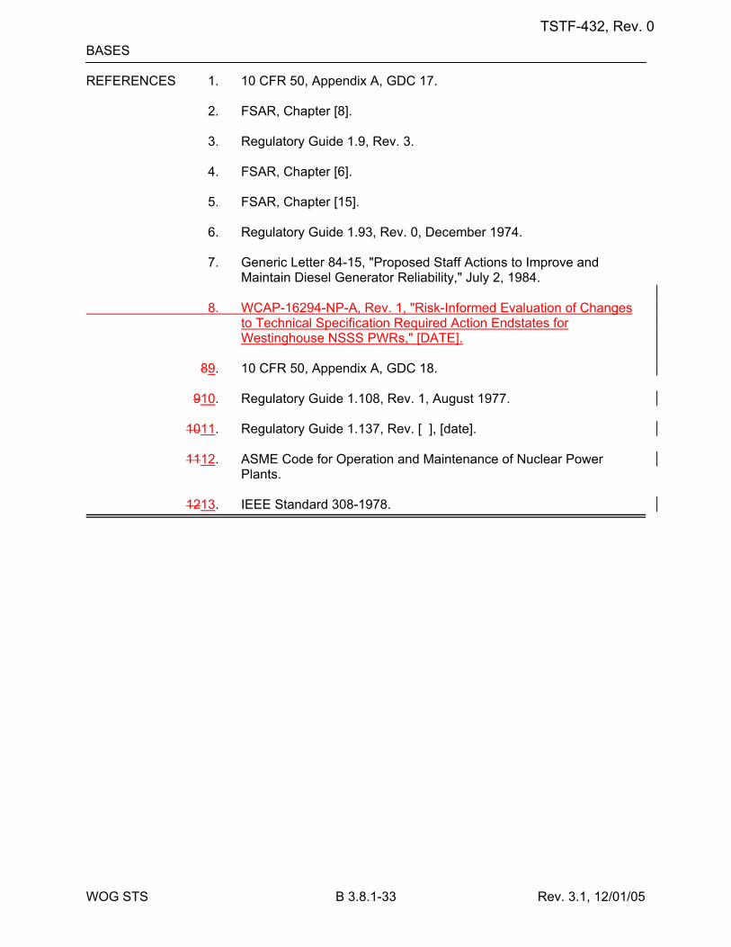
WOG STS B 3.8.1-33 Rev. 3.1, 12/01/05
BASES REFERENCES 1. 10 CFR 50, Appendix A, GDC 17. 2. FSAR, Chapter [8]. 3. Regulatory Guide 1.9, Rev. 3. 4. FSAR, Chapter [6]. 5. FSAR, Chapter [15]. 6. Regulatory Guide 1.93, Rev. 0, December 1974. 7. Generic Letter 84-15, "Proposed Staff Actions to Improve and
Maintain Diesel Generator Reliability," July 2, 1984. 8. WCAP-16294-NP-A, Rev. 1, "Risk-Informed Evaluation of Changes
to Technical Specification Required Action Endstates for Westinghouse NSSS PWRs," [DATE].
89. 10 CFR 50, Appendix A, GDC 18. 910. Regulatory Guide 1.108, Rev. 1, August 1977. 1011. Regulatory Guide 1.137, Rev. [ ], [date]. 1112. ASME Code for Operation and Maintenance of Nuclear Power
Plants. 1213. IEEE Standard 308-1978.
TSTF-432, Rev. 0
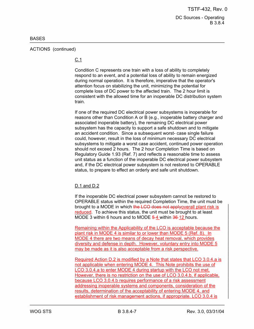
DC Sources - Operating B 3.8.4
WOG STS B 3.8.4-7 Rev. 3.0, 03/31/04
BASES ACTIONS (continued)
C.1 Condition C represents one train with a loss of ability to completely respond to an event, and a potential loss of ability to remain energized during normal operation. It is therefore, imperative that the operator's attention focus on stabilizing the unit, minimizing the potential for complete loss of DC power to the affected train. The 2 hour limit is consistent with the allowed time for an inoperable DC distribution system train. If one of the required DC electrical power subsystems is inoperable for reasons other than Condition A or B (e.g., inoperable battery charger and associated inoperable battery), the remaining DC electrical power subsystem has the capacity to support a safe shutdown and to mitigate an accident condition. Since a subsequent worst- case single failure could, however, result in the loss of minimum necessary DC electrical subsystems to mitigate a worst case accident, continued power operation should not exceed 2 hours. The 2 hour Completion Time is based on Regulatory Guide 1.93 (Ref. 7) and reflects a reasonable time to assess unit status as a function of the inoperable DC electrical power subsystem and, if the DC electrical power subsystem is not restored to OPERABLE status, to prepare to effect an orderly and safe unit shutdown. D.1 and D.2 If the inoperable DC electrical power subsystem cannot be restored to OPERABLE status within the required Completion Time, the unit must be brought to a MODE in which the LCO does not applyoverall plant risk is reduced. To achieve this status, the unit must be brought to at least MODE 3 within 6 hours and to MODE 5 4 within 36 12 hours. Remaining within the Applicability of the LCO is acceptable because the plant risk in MODE 4 is similar to or lower than MODE 5 (Ref. 8). In MODE 4 there are two means of decay heat removal, which provides diversity and defense in depth. However, voluntary entry into MODE 5 may be made as it is also acceptable from a risk perspective. Required Action D.2 is modified by a Note that states that LCO 3.0.4.a is not applicable when entering MODE 4. This Note prohibits the use of LCO 3.0.4.a to enter MODE 4 during startup with the LCO not met. However, there is no restriction on the use of LCO 3.0.4.b, if applicable, because LCO 3.0.4.b requires performance of a risk assessment addressing inoperable systems and components, consideration of the results, determination of the acceptability of entering MODE 4, and establishment of risk management actions, if appropriate. LCO 3.0.4 is
TSTF-432, Rev. 0
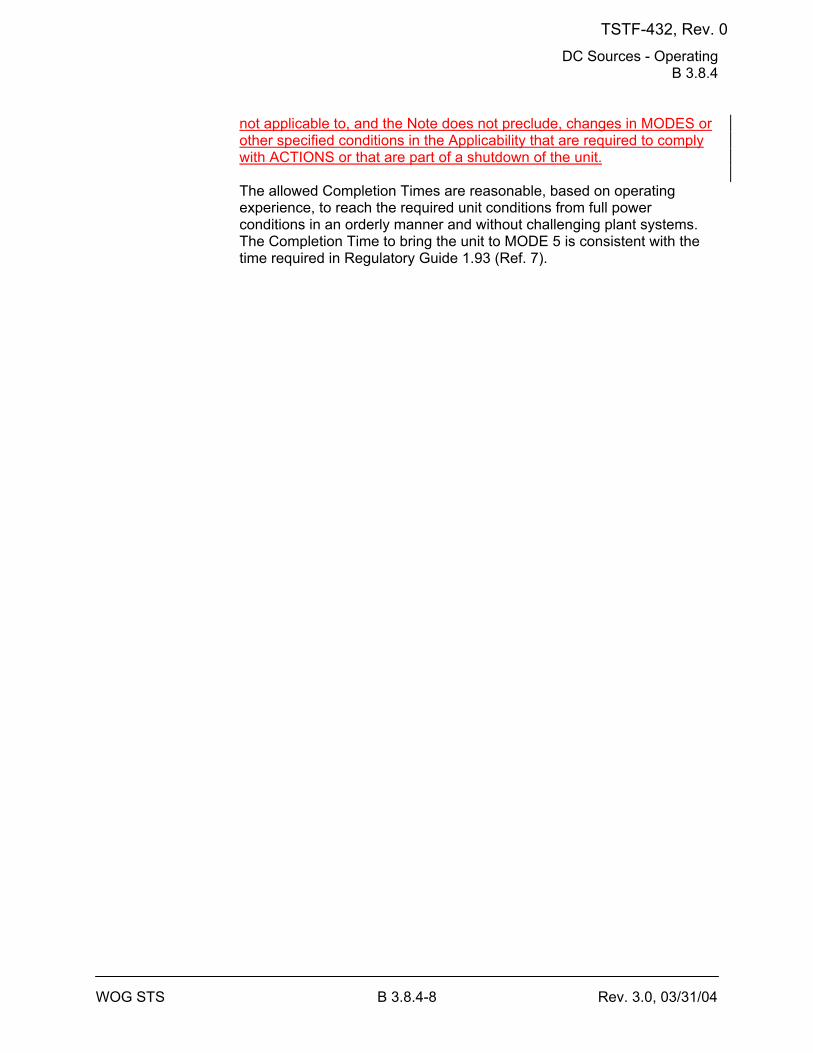
DC Sources - Operating B 3.8.4
WOG STS B 3.8.4-8 Rev. 3.0, 03/31/04
not applicable to, and the Note does not preclude, changes in MODES or other specified conditions in the Applicability that are required to comply with ACTIONS or that are part of a shutdown of the unit. The allowed Completion Times are reasonable, based on operating experience, to reach the required unit conditions from full power conditions in an orderly manner and without challenging plant systems. The Completion Time to bring the unit to MODE 5 is consistent with the time required in Regulatory Guide 1.93 (Ref. 7).
TSTF-432, Rev. 0
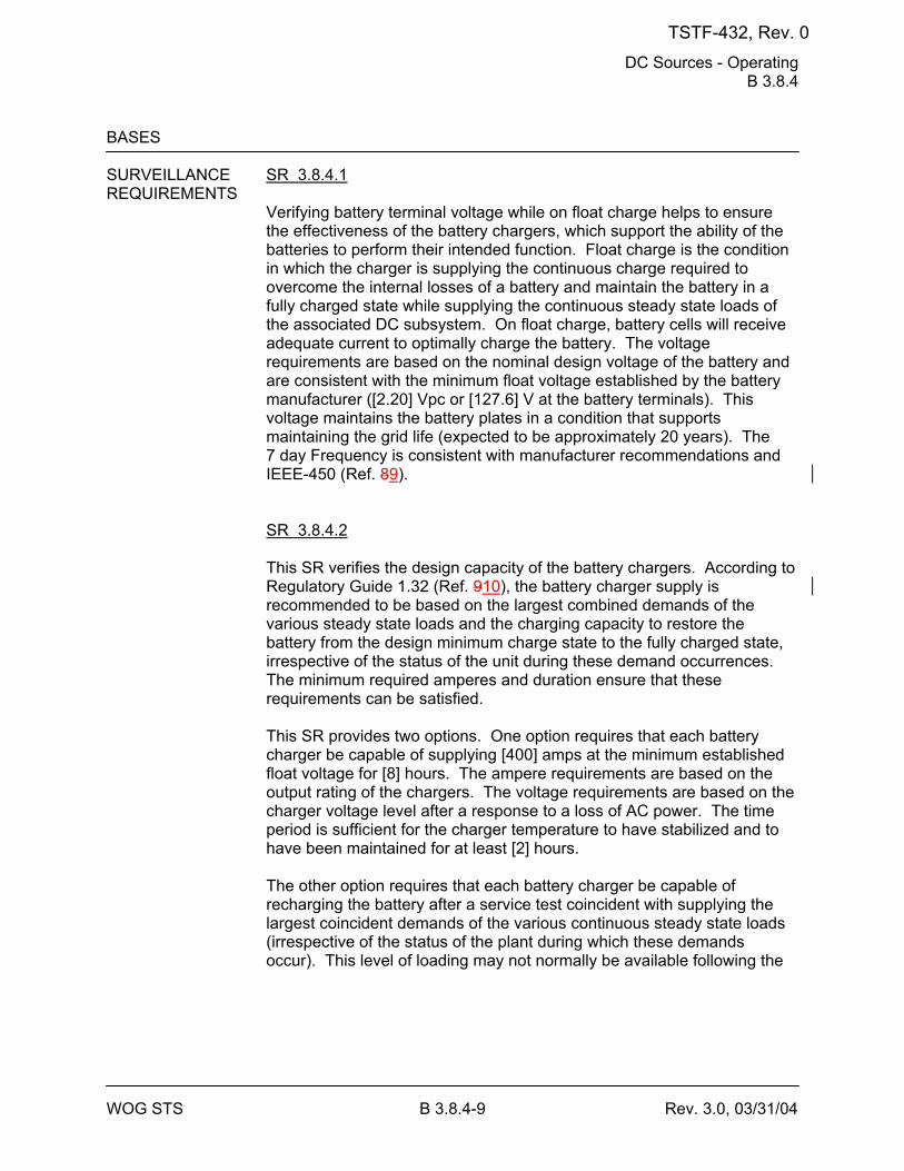
DC Sources - Operating B 3.8.4
WOG STS B 3.8.4-9 Rev. 3.0, 03/31/04
BASES SURVEILLANCE SR 3.8.4.1 REQUIREMENTS
Verifying battery terminal voltage while on float charge helps to ensure the effectiveness of the battery chargers, which support the ability of the batteries to perform their intended function. Float charge is the condition in which the charger is supplying the continuous charge required to overcome the internal losses of a battery and maintain the battery in a fully charged state while supplying the continuous steady state loads of the associated DC subsystem. On float charge, battery cells will receive adequate current to optimally charge the battery. The voltage requirements are based on the nominal design voltage of the battery and are consistent with the minimum float voltage established by the battery manufacturer ([2.20] Vpc or [127.6] V at the battery terminals). This voltage maintains the battery plates in a condition that supports maintaining the grid life (expected to be approximately 20 years). The 7 day Frequency is consistent with manufacturer recommendations and IEEE-450 (Ref. 89). SR 3.8.4.2 This SR verifies the design capacity of the battery chargers. According to Regulatory Guide 1.32 (Ref. 910), the battery charger supply is recommended to be based on the largest combined demands of the various steady state loads and the charging capacity to restore the battery from the design minimum charge state to the fully charged state, irrespective of the status of the unit during these demand occurrences. The minimum required amperes and duration ensure that these requirements can be satisfied. This SR provides two options. One option requires that each battery charger be capable of supplying [400] amps at the minimum established float voltage for [8] hours. The ampere requirements are based on the output rating of the chargers. The voltage requirements are based on the charger voltage level after a response to a loss of AC power. The time period is sufficient for the charger temperature to have stabilized and to have been maintained for at least [2] hours. The other option requires that each battery charger be capable of recharging the battery after a service test coincident with supplying the largest coincident demands of the various continuous steady state loads (irrespective of the status of the plant during which these demands occur). This level of loading may not normally be available following the
TSTF-432, Rev. 0
DC Sources - Operating B 3.8.4
WOG STS B 3.8.4-10 Rev. 3.0, 03/31/04
BASES SURVEILLANCE REQUIREMENTS (continued)
battery service test and will need to be supplemented with additional loads. The duration for this test may be longer than the charger sizing criteria since the battery recharge is affected by float voltage, temperature, and the exponential decay in charging current. The battery is recharged when the measured charging current is ≤ [2] amps. The Surveillance Frequency is acceptable, given the unit conditions required to perform the test and the other administrative controls existing to ensure adequate charger performance during these [18 month] intervals. In addition, this Frequency is intended to be consistent with expected fuel cycle lengths. SR 3.8.4.3 A battery service test is a special test of the battery capability, as found, to satisfy the design requirements (battery duty cycle) of the DC electrical power system. The discharge rate and test length should correspond to the design duty cycle requirements as specified in Reference 4. The Surveillance Frequency of [18 months] is consistent with the recommendations of Regulatory Guide 1.32 (Ref. 910) and Regulatory Guide 1.129 (Ref. 1011), which state that the battery service test should be performed during refueling operations, or at some other outage, with intervals between tests not to exceed [18 months]. This SR is modified by two Notes. Note 1 allows the performance of a modified performance discharge test in lieu of a service test. The reason for Note 2 is that performing the Surveillance would perturb the electrical distribution system and challenge safety systems. This restriction from normally performing the Surveillance in MODE 1 or 2 is further amplified to allow portions of the Surveillance to be performed for the purpose of reestablishing OPERABILITY (e.g., post work testing following corrective maintenance, corrective modification, deficient or incomplete surveillance testing, and other unanticipated OPERABILITY concerns) provided an assessment determines plant safety is maintained or enhanced. This assessment shall, as a minimum, consider the potential outcomes and transients associated with a failed partial
TSTF-432, Rev. 0
DC Sources - Operating B 3.8.4
WOG STS B 3.8.4-11 Rev. 3.0, 03/31/04
BASES SURVEILLANCE REQUIREMENTS (continued)
Surveillance, a successful partial Surveillance, and a perturbation of the offsite or onsite system when they are tied together or operated independently for the partial Surveillance; as well as the operator procedures available to cope with these outcomes. These shall be measured against the avoided risk of a plant shutdown and startup to determine that plant safety is maintained or enhanced when portions of the Surveillance are performed in MODE 1 or 2. Risk insights or deterministic methods may be used for the assessment. Credit may be taken for unplanned events that satisfy this SR.
REFERENCES 1. 10 CFR 50, Appendix A, GDC 17. 2. Regulatory Guide 1.6, March 10, 1971. 3. IEEE-308-[1978]. 4. FSAR, Chapter [8]. 5. FSAR, Chapter [6]. 6. FSAR, Chapter [15]. 7. Regulatory Guide 1.93, December 1974. 8. WCAP-16294-NP-A, Rev. 1, "Risk-Informed Evaluation of Changes
to Technical Specification Required Action Endstates for Westinghouse NSSS PWRs," [DATE].
89. IEEE-450-[1995]. 910. Regulatory Guide 1.32, February 1977. 1011. Regulatory Guide 1.129, December 1974.
TSTF-432, Rev. 0
Inverters - Operating B 3.8.7
WOG STS B 3.8.7-3 Rev. 3.0, 03/31/04
BASES ACTIONS A.1
With a required inverter inoperable, its associated AC vital bus becomes inoperable until it is [manually] re-energized from its [Class 1E constant voltage source transformer or inverter using internal AC source]. For this reason a Note has been included in Condition A requiring the entry into the Conditions and Required Actions of LCO 3.8.9, "Distribution Systems - Operating." This ensures that the vital bus is re-energized within 2 hours. Required Action A.1 allows 24 hours to fix the inoperable inverter and return it to service. The 24 hour limit is based upon engineering judgment, taking into consideration the time required to repair an inverter and the additional risk to which the unit is exposed because of the inverter inoperability. This has to be balanced against the risk of an immediate shutdown, along with the potential challenges to safety systems such a shutdown might entail. When the AC vital bus is powered from its constant voltage source, it is relying upon interruptible AC electrical power sources (offsite and onsite). The uninterruptible inverter source to the AC vital buses is the preferred source for powering instrumentation trip setpoint devices. B.1 and B.2 If the inoperable devices or components cannot be restored to OPERABLE status within the required Completion Time, the unit must be brought to a MODE in which the LCO does not applyoverall plant risk is reduced. To achieve this status, the unit must be brought to at least MODE 3 within 6 hours and to MODE 5 4 within 36 12 hours. Remaining within the Applicability of the LCO is acceptable because the plant risk in MODE 4 is similar to or lower than MODE 5 (Ref. 4). In MODE 4 there are two means of decay heat removal, which provides diversity and defense in depth. However, voluntary entry into MODE 5 may be made as it is also acceptable from a risk perspective. Required Action B.2 is modified by a Note that states that LCO 3.0.4.a is not applicable when entering MODE 4. This Note prohibits the use of LCO 3.0.4.a to enter MODE 4 during startup with the LCO not met. However, there is no restriction on the use of LCO 3.0.4.b, if applicable, because LCO 3.0.4.b requires performance of a risk assessment addressing inoperable systems and components, consideration of the results, determination of the acceptability of entering MODE 4, and establishment of risk management actions, if appropriate. LCO 3.0.4 is not applicable to, and the Note does not preclude, changes in MODES or
TSTF-432, Rev. 0
Inverters - Operating B 3.8.7
WOG STS B 3.8.7-4 Rev. 3.0, 03/31/04
other specified conditions in the Applicability that are required to comply with ACTIONS or that are part of a shutdown of the unit. The allowed Completion Times are reasonable, based on operating experience, to reach the required unit conditions from full power conditions in an orderly manner and without challenging plant systems.
TSTF-432, Rev. 0
Inverters - Operating B 3.8.7
WOG STS B 3.8.7-5 Rev. 3.0, 03/31/04
BASES SURVEILLANCE SR 3.8.7.1 REQUIREMENTS
This Surveillance verifies that the inverters are functioning properly with all required circuit breakers closed and AC vital buses energized from the inverter. The verification of proper voltage and frequency output ensures that the required power is readily available for the instrumentation of the RPS and ESFAS connected to the AC vital buses. The 7 day Frequency takes into account the redundant capability of the inverters and other indications available in the control room that alert the operator to inverter malfunctions.
REFERENCES 1. FSAR, Chapter [8]. 2. FSAR, Chapter [6]. 3. FSAR, Chapter [15]. 4. WCAP-16294-NP-A, Rev. 1, "Risk-Informed Evaluation of Changes
to Technical Specification Required Action Endstates for Westinghouse NSSS PWRs," [DATE].
TSTF-432, Rev. 0
Distribution Systems - Operating B 3.8.9
WOG STS B 3.8.9-6 Rev. 3.1, 12/01/05
BASES ACTIONS (continued)
Condition C represents one or more DC buses or distribution panels without adequate DC power; potentially both with the battery significantly degraded and the associated charger nonfunctioning. In this situation, the unit is significantly more vulnerable to a complete loss of all DC power. It is, therefore, imperative that the operator's attention focus on stabilizing the unit, minimizing the potential for loss of power to the remaining trains and restoring power to the affected train. This 2 hour limit is more conservative than Completion Times allowed for the vast majority of components that would be without power. Taking exception to LCO 3.0.2 for components without adequate DC power, which would have Required Action Completion Times shorter than 2 hours, is acceptable because of: a. The potential for decreased safety by requiring a change in unit
conditions (i.e., requiring a shutdown) while allowing stable operations to continue,
b. The potential for decreased safety by requiring entry into numerous
applicable Conditions and Required Actions for components without DC power and not providing sufficient time for the operators to perform the necessary evaluations and actions for restoring power to the affected train, and
c. The potential for an event in conjunction with a single failure of a
redundant component. The 2 hour Completion Time for DC buses is consistent with Regulatory Guide 1.93 (Ref. 3). D.1 and D.2 If the inoperable distribution subsystem cannot be restored to OPERABLE status within the required Completion Time, the unit must be brought to a MODE in which the LCO does not applyoverall plant risk is reduced. To achieve this status, the unit must be brought to at least MODE 3 within 6 hours and to MODE 5 4 within 36 12 hours. Remaining within the Applicability of the LCO is acceptable because the plant risk in MODE 4 is similar to or lower than MODE 5 (Ref. 4). In MODE 4 there are two means of decay heat removal, which provides diversity and defense in depth. However, voluntary entry into MODE 5 may be made as it is also acceptable from a risk perspective.
TSTF-432, Rev. 0
Distribution Systems - Operating B 3.8.9
WOG STS B 3.8.9-7 Rev. 3.1, 12/01/05
Required Action D.2 is modified by a Note that states that LCO 3.0.4.a is not applicable when entering MODE 4. This Note prohibits the use of LCO 3.0.4.a to enter MODE 4 during startup with the LCO not met. However, there is no restriction on the use of LCO 3.0.4.b, if applicable, because LCO 3.0.4.b requires performance of a risk assessment addressing inoperable systems and components, consideration of the results, determination of the acceptability of entering MODE 4, and establishment of risk management actions, if appropriate. LCO 3.0.4 is not applicable to, and the Note does not preclude, changes in MODES or other specified conditions in the Applicability that are required to comply with ACTIONS or that are part of a shutdown of the unit. The allowed Completion Times are reasonable, based on operating experience, to reach the required unit conditions from full power conditions in an orderly manner and without challenging plant systems.
TSTF-432, Rev. 0
Distribution Systems - Operating B 3.8.9
WOG STS B 3.8.9-8 Rev. 3.1, 12/01/05
BASES ACTIONS (continued)
E.1 Condition E corresponds to a level of degradation in the electrical power distribution system that causes a required safety function to be lost. When more than one inoperable electrical power distribution subsystem results in the loss of a required function, the plant is in a condition outside the accident analysis. Therefore, no additional time is justified for continued operation. LCO 3.0.3 must be entered immediately to commence a controlled shutdown.
SURVEILLANCE SR 3.8.9.1 REQUIREMENTS
This Surveillance verifies that the [required] AC, DC, and AC vital bus electrical power distribution systems are functioning properly, with the correct circuit breaker alignment. The correct breaker alignment ensures the appropriate separation and independence of the electrical divisions is maintained, and the appropriate voltage is available to each required bus. The verification of proper voltage availability on the buses ensures that the required voltage is readily available for motive as well as control functions for critical system loads connected to these buses. The 7 day Frequency takes into account the redundant capability of the AC, DC, and AC vital bus electrical power distribution subsystems, and other indications available in the control room that alert the operator to subsystem malfunctions.
REFERENCES 1. FSAR, Chapter [6]. 2. FSAR, Chapter [15]. 3. Regulatory Guide 1.93, December 1974. 4. WCAP-16294-NP-A, Rev. 1, "Risk-Informed Evaluation of Changes
to Technical Specification Required Action Endstates for Westinghouse NSSS PWRs," [DATE].
TSTF-432, Rev. 0
11921 Rockville Pike, Suite 100, Rockville, MD 20852 Phone: 301-984-4400, Fax: 301-984-7600 Administration by EXCEL Services Corporation
TECHNICAL SPECIFICATIONS TASK FORCEA JOINT OWNERS GROUP ACTIVITYTSTF
TSTF-IG-05-02
IMPLEMENTATION GUIDANCE FOR TSTF-423, REVISION 1,
"TECHNICAL SPECIFICATIONS END STATES, NEDC-32988-A"
REVISION 2 NOVEMBER 2009
TSTF-IG-05-02, Rev. 2 November 2009
ACKNOWLEDGMENTS
This document, Implementation Guidance for TSTF-423, Revision 1, "Technical Specifications End States, NEDC-32988-A," was developed by the Boiling Water Reactor Owners Group (BWROG), the Nuclear Energy Institute (NEI) Risk Informed Technical Specification Task Force (RITSTF), and the Technical Specifications Task Force (TSTF). The TSTF wishes to acknowledge the efforts of John D. (Don) McCamy of the Tennessee Valley Authority, George S. (Steve) Cashell of DTE Energy, the NEI RITSTF, the BWROG, and U.S. Nuclear Regulatory Commission reviewers, in creating this document.
REVISION DESCRIPTION Revision 1 modifies Section 1, numbered items 4 and 5,which state:
4. If Primary Containment is not operable, Secondary Containment and Standby Gas Treatment must be verified operable in order to remain in Mode 3, unless a plant specific risk evaluation is prepared.
5. If Secondary Containment is not operable, Primary Containment must be verified operable in order to remain in Mode 3, unless a plant specific risk evaluation is prepared.
In both items, the phrase, ", unless a plant specific risk evaluation is prepared" is deleted. This revision was requested by the NRC. This option was not discussed in the NRC's Safety Evaluation for TSTF-423. Revision 2 eliminates Section 1, numbered item 4,which states:
4. If Primary Containment is not operable, Secondary Containment and Standby Gas Treatment must be verified operable in order to remain in Mode 3, unless a plant specific risk evaluation is prepared.
Primary Containment is no longer included in TSTF-423. When Primary Containment is inoperable, plant shutdown to MODE 4 is required. The subsequent items have been renumbered.

TSTF-IG-05-02, Rev. 2 November 2009
i
TABLE OF CONTENTS
ACKNOWLEDGMENTS AND REVISION DESCRIPTION TABLE OF CONTENTS ................................................................................................. i 1 Impact on the Maintenance Rule (A)(4) Program for Assessment and
Management of Risk ............................................................................................... 1 2 RISK ASSESSMENT AND MANAGEMENT CONSIDERATIONS .................... 2
2.1 Methods of Assessment ................................................................................... 2 2.2 Considerations from BWROG Topical Report ................................................ 3 2.3 General Guidance ............................................................................................ 3
3 DOCUMENTATION ............................................................................................... 4 4 REFERENCES ........................................................................................................ 4
TSTF-IG-05-02, Rev. 2 November 2009
1
1 IMPACT ON THE MAINTENANCE RULE (A)(4) PROGRAM FOR ASSESSMENT AND MANAGEMENT OF RISK
The technical basis for the preferred end states initiative is contained in NEDC-32988-A, "Technical Justification to Support Risk-Informed Modification to Selected Required Action End States for BWR Plants" (Reference 1), and the associated NRC Safety Evaluation (Reference 2). The report concluded, and the NRC concurred, that for short duration operation, Mode 3 (hot shutdown) is a risk neutral or risk beneficial end state compared to Mode 4 (cold shutdown). A "short duration" is envisioned to be the duration that boiling water reactors (BWRs) are most physically and practicably able to remain in the hot shutdown condition (i.e., from a few days to approximately one week). The risk benefit from this change is largely due to the availability of increased heat removal resources in Mode 3.
The analyses described in Reference 1 were used to create TSTF-423, "Technical Specifications End States, NEDC-32988-A" (Reference 3). TSTF-423 modifies NUREGs 1433 and 1434, the Improved Standard Technical Specifications (ISTS) for BWR/4 and BWR/6 plants. TSTF-423 modifies the end state for a limited set of Technical Specifications (TS) which are applicable in Modes 1, 2, and 3 to allow operation in Mode 3 with equipment governed by the TS inoperable.
Implementation of the preferred end states initiative requires some modification of the current program for implementing 10 CFR 50.65(a)(4), the Maintenance Rule. These modifications are intended to preclude preventive maintenance and operational activities being performed on equipment combinations that could lead to reduced defense-in-depth and potentially high risk configurations, and to identify actions for expeditiously exiting a risk-significant configuration should it occur. These modifications are discussed below:
1. Plants implementing TSTF-423 must commit to the guidance contained in NUMARC 93-01, "Industry Guideline for Monitoring the Effectiveness of Maintenance at Nuclear Power Plants" (Reference 4), Section 11, for Maintenance Rule risk assessments. NRC Regulatory Guide 1.182, "Assessing and Managing Risk Before Maintenance Activities at Nuclear Power Plants" (Reference 5), states that the NUMARC guidance is one acceptable approach for implementing 10 CFR 50.65(a)(4). The guidance provides flexibility with respect to risk assessment and management approaches and allows for a combination of qualitative and quantitative evaluations, as well as use of bounding assessments.
2. Use of the preferred end state to perform maintenance will require a risk assessment consistent with 10 CFR 50.65(a)(4). Qualitative assessments that recognize the contemporaneous configuration and refer to insights identified in the Topical Report (Reference 1) are acceptable, as are bounding quantitative
TSTF-IG-05-02, Rev. 2 November 2009
2
assessments. Assessments may credit existing analyses and insights drawn from Reference 1 as they apply to the current plant operating condition.
3. Should contemporaneous risk assessments result in the identification of a high risk configuration, risk management actions should be taken. These actions may include exiting Mode 3 to a Mode in which the risk is reduced.
4. If Secondary Containment is not operable, Primary Containment must be verified operable in order to remain in Mode 3.
5. Any entry into Mode 3 using this TS allowance must be limited to no more than seven days.
6. Although not mandatory, plants should attempt to reduce pressure to less than 500 psig within 12 hours after entering Mode 3. Risk should be assessed for those periods of time that the plant is above 500 psig after 12 hours in Mode 3.
7. Plants submitting a license amendment to adopt the preferred end states described in Reference 1 and TSTF-423 must commit to implementing the guidance in this document.
2 RISK ASSESSMENT AND MANAGEMENT CONSIDERATIONS
This section describes considerations for risk assessment and management relative to implementation of TSTF-423.
2.1 Methods of Assessment
NUMARC 93-01 provides separate guidance for risk assessment during power operation (Section 11.3.4), and during shutdown conditions (Section 11.3.6). Thus, Section 11.3.6, Shutdown Conditions, of NUMARC 93-01 contains the appropriate guidance for performing risk assessments for maintenance while utilizing the preferred end states initiative. The NUMARC 93-01 guidance is based on maintaining defense-in-depth for key safety functions necessary for safe shutdown. Reference 1 uses both qualitative and quantitative evaluations of representative plants to demonstrate that the risk impact from remaining in Mode 3 is equal to or less than that in going to Mode 4, and that extended operation in Mode 3 is thus acceptable.
It is expected that consideration of the risk impact of maintenance performed while in the preferred end state will generally be performed qualitatively, or through a combination of qualitative and quantitative methods. For those plants capable of

TSTF-IG-05-02, Rev. 2 November 2009
3
quantification, the risk impact of maintenance while in the preferred end state may be quantified, compared to risk management thresholds provided in section 11.3.7.2 of NUMARC 93-01, and appropriate risk management actions implemented.
In performing the risk assessments for maintenance while in Mode 3, the use of a key safety function defense-in-depth approach, as discussed in NUMARC 91-06, "Shutdown Risk Management" (Reference 6), and Section 11 of NUMARC 93-01 is considered an acceptable approach for satisfying the requirements regarding risk assessment and management. In performing this assessment, it should be ensured that adequate defense-in-depth for key safety functions will be preserved when performing maintenance while utilizing the preferred end state. Application of the key safety function approach to Mode 3 may require additional considerations relative to the reactor coolant being at higher temperature and being above atmospheric pressure. Quantitative lower Mode risk assessments may also be used provided appropriate tools and models are available.
2.2 Considerations from BWROG Topical Report
When implementing the Mode 3 allowance, the BWROG Topical Report (Reference 1) and the NRC safety evaluation (Reference 2) contain valuable information with respect to remaining in Mode 3. This information should be incorporated in plant operating procedures and practices as applicable.
2.3 General Guidance
The following general guidance is provided for performing risk assessments of maintenance performed while remaining in Mode 3 as allowed by TSTF-423:
1. When performing risk assessments and risk management of maintenance performed while in the Mode 3 end state, the licensees must consider all maintenance being performed, regardless of whether the maintenance is related to restoring the inoperable equipment which lead to the use of the Mode 3 end state.
2. If plant conditions change during performance of maintenance, 10 CFR 50.65(a)(4) requires the new condition to be evaluated, and if necessary, risk management actions to be taken. The actions may include stopping the maintenance activity, completing the activity, transitioning the plant to a lower Mode, or other risk management actions. These actions are implemented in plant procedures.
TSTF-IG-05-02, Rev. 2 November 2009
4
3 DOCUMENTATION
Programs for risk assessment and management are required to be proceduralized in accordance with NUMARC 93-01; however, documentation of each individual use of the risk assessment and risk management actions for maintenance performed while utilizing the preferred end state is not required by NRC. Although not required, it may be prudent to document these activities for internal reasons, including communication between plant organizations, turnover of operating crews, consistency of application, and clear communication of risk management actions to appropriate plant personnel.
4 REFERENCES
1. NEDC-32988-A, Revision 2, "Technical Justification to Support Risk-Informed Modification to Selected Required Action End States for BWR Plants," dated December 2002.
2. NRC Safety Evaluation for Topical Report NEDC-32988, Revision 2, dated September 27, 2002.
3. TSTF-423, Revision 1, "Technical Specifications End States, NEDC-32988-A."
4. NUMARC 93-01, "Industry Guideline For Monitoring The Effectiveness Of Maintenance At Nuclear Power Plants," Revision 3, July 2000.
5. NUREG 1.182, "Assessing and Managing Risk Before Maintenance Activities at Nuclear Power Plants," May 2000.
6. NUMARC 91-06, "Shutdown Risk Management," December 1991.
11921 Rockville Pike, Suite 100, Rockville, MD 20852 Phone: 301-984-4400, Fax: 301-984-7600 Administration by EXCEL Services Corporation
TECHNICAL SPECIFICATIONS TASK FORCEA JOINT OWNERS GROUP ACTIVITYTSTF
TSTF-IG-07-01
IMPLEMENTATION GUIDANCE FOR TSTF-431, REVISION 3,
"CHANGE IN TECHNICAL SPECIFICATIONS END STATES
(BAW-2441)"
REVISION 1 NOVEMBER 2009
TSTF-IG-07-01, Rev. 1 November 2009
ACKNOWLEDGMENTS
This document, Implementation Guidance for TSTF-431, Revision 3, "Change in Technical Specifications End States (BAW-2441)," was developed by the Technical Specifications Task Force (TSTF), AREVA NP, the Pressurized Water Reactors Owners Group (PWROG), and the Nuclear Energy Institute (NEI) Risk Informed Technical Specification Task Force (RITSTF).
REVISION DESCRIPTION Revision 1 updates references to TSTF-431 to Revision 3 of the Traveler.
TSTF-IG-07-01, Rev. 1 November 2009
i
TABLE OF CONTENTS
ACKNOWLEDGMENTS AND REVISION DESCRIPTION TABLE OF CONTENTS ................................................................................................. i 1 Impact on the Maintenance Rule (A)(4) Program for Assessment and
Management of Risk ............................................................................................... 1 2 RISK ASSESSMENT AND MANAGEMENT CONSIDERATIONS .................... 2
2.1 Methods of Assessment ................................................................................... 2 2.2 Considerations from Topical Report ............................................................... 3 2.3 General Guidance ............................................................................................ 3
3 DOCUMENTATION ............................................................................................... 3 4 REFERENCES ........................................................................................................ 4
TSTF-IG-07-01, Rev. 1 November 2009
1
1 IMPACT ON THE MAINTENANCE RULE (A)(4) PROGRAM FOR ASSESSMENT AND MANAGEMENT OF RISK
The technical basis for the preferred end states initiative is contained in BAW-2441, Revision 2, "Risk Informed Justification for LCO End-State Changes," (Reference 1) and the associated NRC Safety Evaluation (Reference 2). The report concluded, and the NRC concurred, that for short duration operation, Mode 4 (hot shutdown) is a risk neutral or risk beneficial end state compared to Mode 5 (cold shutdown). The risk benefit from this change is largely due to the availability of increased heat removal resources in Mode 4.
The analyses described in Reference 1 were used to create TSTF-431, "Change in Technical Specifications End States (BAW-2441)" (Reference 3). TSTF-431 modifies NUREG-1430, the Improved Standard Technical Specifications (ISTS) for Babcock and Wilcox plants. TSTF-431 modifies the end state for a limited set of Technical Specifications (TS) which are applicable in Modes 1, 2, 3, and 4 to allow operation in Mode 4 when equipment governed by the TS is inoperable.
Implementation of the preferred end states initiative requires some modification of the current program for implementing 10 CFR 50.65(a)(4), the Maintenance Rule. These modifications are intended to preclude preventive maintenance and operational activities being performed on equipment combinations that could lead to reduced defense-in-depth and potentially high risk configurations, and to identify actions for expeditiously exiting a risk-significant configuration should it occur. These modifications are discussed below:
1. Plants implementing TSTF-431 must commit to the guidance contained in NUMARC 93-01, "Industry Guideline for Monitoring the Effectiveness of Maintenance at Nuclear Power Plants" (Reference 4), Section 11, for Maintenance Rule risk assessments. NRC Regulatory Guide 1.182, "Assessing and Managing Risk Before Maintenance Activities at Nuclear Power Plants" (Reference 5), states that the NUMARC guidance is one acceptable approach for implementing 10 CFR 50.65(a)(4). The guidance provides flexibility with respect to risk assessment and management approaches and allows for a combination of qualitative and quantitative evaluations, as well as use of bounding assessments.
2. Use of the preferred end state to perform maintenance will require a risk assessment consistent with 10 CFR 50.65(a)(4). Qualitative assessments that recognize the contemporaneous configuration and refer to insights identified in the Topical Report (Reference 1) are acceptable, as are bounding quantitative assessments. Assessments may credit existing analyses and insights drawn from Reference 1 as they apply to the current plant operating condition.
TSTF-IG-07-01, Rev. 1 November 2009
2
3. Use of the preferred end state is for a short interval, with the primary intent being to repair a nonfunctional component and return the plant to power as soon as practical.
4. Should contemporaneous risk assessments result in the identification of a high risk configuration, risk management actions should be taken. These actions may include exiting Mode 4 to a Mode in which the risk is reduced.
5. Plants submitting a license amendment to adopt the preferred end states described in Reference 1 and TSTF-431 must commit to implementing the guidance in this document.
2 RISK ASSESSMENT AND MANAGEMENT CONSIDERATIONS
This section describes considerations for risk assessment and management relative to implementation of TSTF-431.
2.1 Methods of Assessment
NUMARC 93-01 provides separate guidance for risk assessment during power operation (Section 11.3.4), and during shutdown conditions (Section 11.3.6). Thus, Section 11.3.6, Assessment Methods for Shutdown Conditions, of NUMARC 93-01 contains the appropriate guidance for performing risk assessments for maintenance while utilizing the preferred end states initiative. The NUMARC 93-01 guidance is based on maintaining defense-in-depth for key safety functions necessary for safe shutdown. Reference 1 uses both qualitative and quantitative evaluations of representative plants to demonstrate that the risk impact from remaining in Mode 4 is equal to or less than that in going to Mode 5, and that the proposed operation in Mode 4 is thus acceptable.
It is expected that consideration of the risk impact of maintenance performed while in the preferred end state will generally be performed qualitatively, or through a combination of qualitative and quantitative methods. For those plants capable of quantification, the risk impact of maintenance while in the preferred end state may be quantified, compared to risk management thresholds provided in section 11.3.7.2 of NUMARC 93-01, and appropriate risk management actions implemented.
In performing the risk assessments for maintenance while in Mode 4, the use of a key safety function defense-in-depth approach, as discussed in NUMARC 91-06, "Guidelines for Industry Actions to Assess Shutdown Management" (Reference 6), and Section 11 of NUMARC 93-01, is considered an acceptable approach for satisfying the requirements regarding risk assessment and management. In
TSTF-IG-07-01, Rev. 1 November 2009
3
performing this assessment, it should be ensured that adequate defense-in-depth for key safety functions will be preserved when performing maintenance while utilizing the preferred end state. Application of the key safety function approach to Mode 4 may require additional considerations relative to the reactor coolant being at higher temperature and being above atmospheric pressure. Quantitative lower Mode risk assessments may also be used provided appropriate tools and models are available.
2.2 Considerations from Topical Report
When implementing the Mode 4 allowance, the Topical Report (Reference 1) and the NRC safety evaluation (Reference 2) contain valuable information with respect to remaining in Mode 4. This information should be incorporated in plant operating procedures and practices as applicable.
2.3 General Guidance
The following general guidance is provided for performing risk assessments of maintenance performed while remaining in Mode 4 as allowed by TSTF-431:
1. When performing risk assessments and risk management of maintenance performed while in the Mode 4 end state, the licensees must consider all maintenance being performed, regardless of whether the maintenance is related to restoring the inoperable equipment which lead to the use of the Mode 4 end state.
2. If plant conditions change during performance of maintenance, 10 CFR 50.65(a)(4) requires the new condition to be evaluated, and if necessary, risk management actions to be taken. The actions may include stopping the maintenance activity, completing the activity, transitioning the plant to a lower Mode, or other risk management actions. These actions are implemented in plant procedures.
3 DOCUMENTATION
Programs for risk assessment and management are required to be proceduralized in accordance with NUMARC 93-01; however, documentation of each individual use of the risk assessment and risk management actions for maintenance performed while utilizing the preferred end state is not required by NRC. Although not required, it may be prudent to document these activities for internal reasons, including communication between plant organizations, turnover of operating crews, consistency of application, and clear communication of risk management actions to appropriate plant personnel.
TSTF-IG-07-01, Rev. 1 November 2009
4
4 REFERENCES
1. BAW-2441-A, Revision 2, "Risk Informed Justification for LCO End-State Changes," September 2006.
2. Letter from H. K. Neih (NRC) to G. Bishoff (PWROG), "Final Safety Evaluation for BAW-2441, Revision 2, 'Risk Informed Justification for LCO End-State Changes'," dated August 25, 2006.
3. TSTF-431, Revision 3, "Change in Technical Specifications End States (BAW-2441)."
4. NUMARC 93-01, "Industry Guideline For Monitoring The Effectiveness Of Maintenance At Nuclear Power Plants," Revision 3, July 2000.
5. NUREG 1.182, "Assessing and Managing Risk Before Maintenance Activities at Nuclear Power Plants," May 2000.
6. NUMARC 91-06, "Guidelines for Industry Actions to Assess Shutdown Management," December 1991.


![I TECHNICAL SPECIFICATIONS TASK FORCE TSTF A JCY]VT CI'WJVERS GR 4CXrP A C77 VIT-Y · 2012-12-03 · I TECHNICAL SPECIFICATIONS TASK FORCE TSTF A JCY]VT CI'WJVERS GR 4CXrP A C77 VIT-Y](https://img.pdfslide.us/doc/110x75/5e84f8eb5e3521594022e8fc/i-technical-specifications-task-force-tstf-a-jcyvt-ciwjvers-gr-4cxrp-a-c77-vit-y.jpg)