Embed Size (px)
Citation preview
NUMARC 93-011REVISION 22
345678
NUCLEAR ENERGY INSTITUTE9
10
11
12
13
14INDUSTRY GUIDELINE FOR MONITORING15
THE EFFECTIVENESS OF MAINTENANCE AT16NUCLEAR POWER PLANTS17
18192021222324252627282930313233
APRIL 199634

ACKNOWLEDGMENTS123
This guidance document, Industry Guideline for Monitoring the Effectiveness of Maintenance at4Nuclear Power Plants, NUMARC 93-01, was developed by the NUMARC Maintenance5Working Group, Ad Hoc Advisory Committees for the Implementation of the Maintenance Rule,6and an Ad Hoc Advisory Committee (AHAC) for the Verification and Validation of the Industry7Maintenance Guideline. We appreciate the direct participation of the many utilities who8contributed to the initial development of the guideline and the participation of the balance of the9industry who reviewed and submitted comments to improve the document clarity and10consistency. The dedicated and timely effort of the many AHAC participants, including their11management's support of the effort, is greatly appreciated.12
13NUMARC also wishes to express its appreciation to the Institute of Nuclear Power Operations14(INPO), and the Electric Power Research Institute (EPRI) who devoted considerable time and15resources to the development and verification and validation of the industry maintenance16guideline. 17
18192021222324252627282930
NOTICE313233
Neither Nuclear Management and Resources Council, nor any of its employees, members,34supporting organizations, contractors or consultants make any warranty, expressed or implied, or35assume any legal responsibility for the accuracy or completeness of, or assume any liability for36damages resulting from any use of, any information apparatus, method, or process disclosed in37this report or that such may not infringe privately owned rights.38
39
i
FOREWORD123
On July 10, 1991, the NRC published in the Federal Register (56 Fed. Reg. 31324) its final4Maintenance Rule entitled, "Requirements for Monitoring the Effectiveness of Maintenance at5Nuclear Power Plants." In the Supplementary Information published with the notice, the6Commission stated that it, "believes that effectiveness of maintenance must be assessed on an7ongoing basis in a manner which ensures that the desired result, reasonable assurance that key8structures, systems, and components (SSCs) are capable of performing their intended function, is9consistently achieved."10
11The importance of proper maintenance to safe and reliable nuclear plant operation has long been12recognized by the nuclear utility industry and the Nuclear Regulatory Commission (NRC). The13industry, since 1982, has placed increased emphasis on improving maintenance because of its14importance in improving overall plant performance. The industry recognizes that good15maintenance is good business and is not an option, but a necessity. Throughout this period,16senior industry management has continued to assure the NRC of its complete commitment to the17goal of improved safety and reliability through better maintenance. This commitment to better18maintenance is reflected in the efforts of the individual nuclear utilities, the Institute of Nuclear19Power Operations (INPO), the Electric Power Research Institute (EPRI), the Nuclear20Management and Resources Council (NUMARC), the four Vendor Owners' Groups and others. 21This commitment has resulted in improved maintenance facilities, enhanced training of22maintenance personnel, increased emphasis on good maintenance work practices and use of23procedures, better technical guidance, and tracking of equipment performance. It also includes24the formation of special industry centers to assist with maintenance-related issues and25applications (e.g., the Nuclear Maintenance Assistance Center).26
27The industry's efforts have resulted in significant progress in improved maintenance that is28demonstrated by many U.S. plants attaining world-class performance by all measurements,29including industry overall performance indicators, and NRC inspections and reports.30
31This industry guideline has been developed to assist the industry in implementing the final32Maintenance Rule and to build on the significant progress, programs and facilities established to33improve maintenance. The guideline provides a process for deciding which of the many34structures, systems, and components that make up a commercial nuclear power plant are within35the scope of the Maintenance Rule. It then describes the process of establishing plant-specific36risk significant and performance criteria to be used to decide if goals need to be established for37specific structures, systems, trains and components covered by the Maintenance Rule that do not38meet their performance criteria. It should be recognized that establishing performance criteria39can be interpreted as establishing goals. However, as used in this guideline, the approach is to40first establish an acceptable set of performance criteria and monitor the structures, systems, and41components against those criteria. This is an ongoing activity. If performance criteria are not42

FOREWORD (continued)
ii
met, then goals are established to bring about the necessary improvements in performance. It is1important to note that the word "goal" as used in this guideline is used only where performance2criteria are not being met. This provides the necessary focus at all levels within the utility where3additional attention is needed.4
5The industry and the NRC recognize that effective maintenance provides reasonable assurance6that key structures, systems, and components are capable of performing their intended function. 7The guideline provides focus on maintenance activities and manpower use to assure the8performance of safety functions by maximizing the use of proven existing industry and9individual plant maintenance programs and minimizing the dilution of critical resources to10modify maintenance programs when established performance criteria are being met.11
12

1 The text of the Maintenance Rule is included in this guideline as Appendix A and the methodology
for selecting SSCs to be included within the scope of the rule is further described in Section 8.0 of thisguideline.
2 As used in this guideline, (a)(1), (a)(2), (a)(3), (b)(1), or (b)(2) refer to the paragraphs included in 101
CFR 50.65.2
3
3 Refer to the Appendix B definition and examples of standby systems and trains.1
2
iii
EXECUTIVE SUMMARY123
This Executive Summary provides a brief review of the key elements of this guideline and4describes the overall process for implementation. The Foreword to this guideline provides a5perspective on the purpose and intent of the guideline.6
7The Industry Guideline Implementation Logic Diagram (Figure 1) describes the process for8implementing the Maintenance Rule. The numbers to the upper right of the activity or decision9on the logic diagram correspond to the section in the guideline where the topic is discussed.10
11Utilities are required to identify safety-related and nonsafety-related plant structures, systems,12and components as described by (b)(1) and (b)(2) of the Maintenance Rule1. For structures,13systems, and components not within the scope of the Maintenance Rule, each utility should14continue existing maintenance programs.15
16As of July 10, 1996, the implementation date of the Maintenance Rule, all SSCs that are within17the scope of the Maintenance Rule will have been placed in (a)(2) and be part of the preventive18maintenance program. To be placed in (a)(2), the SSC will have been determined to have19acceptable performance. In addition, those SSCs with unacceptable performance will be placed20in (a)(1)2 with goals established. This determination is made by considering the risk significance21as well as the performance of the structures, systems, and components against plant-specific22performance criteria. Specific performance criteria are established for those structures, systems,23and components that are either risk significant or standby mode3; the balance are monitored24against the overall plant level performance criteria. The high pressure coolant injection system is25an example of a system that is in a standby mode during normal plant operations and is expected26to perform its safety function on demand. It should be recognized that the performance of the27support systems (e.g., HVAC) may have a direct impact on the primary system's performance28

EXECUTIVE SUMMARY (continued)
4 As used in this guideline the scope of IPE includes both internal and external events.1
2
iv
(e.g., availability).12
The process addressing (a)(1) includes establishing goals for structures, systems, trains, or3components that have not demonstrated acceptable performance. It should be noted that the key4parameter is performance.5
6Risk significant structures, systems, and components should be identified by using an Individual7Plant Examination4, a Probabilistic Risk Assessment, critical safety functions (e.g., inventory), or8other processes, provided they are systematic and documented.9
10The performance of structures, systems, or components that are determined to not meet the11performance criteria established by a utility shall be subjected to goal setting and monitoring that12leads to acceptable performance. For those structures, systems, trains, or components requiring13goal setting, it is expected that many goals will be set at the system level. In addition, train and14component level goals should be established (Section 9.0) when determined appropriate by the15utility. Performance of structures, systems, trains, or components against established goals will16be monitored until it is determined that the goals have been achieved and performance can be17addressed in (a)(2).18
19Structures, systems, and components within the scope of the Maintenance Rule whose20performance is currently determined to be acceptable will be assessed to assure that acceptable21performance is sustained (Section 10.0).22
23Although goals are established and monitored as part of (a)(1), the preventive maintenance and 24performance monitoring activities are part of (a)(2) and apply to the structures, systems, and25components that are within the scope of the Maintenance Rule.26
27An assessment of the overall effect on plant safety will be performed for structures, systems, and28components that support plant safety functions when they are taken out of service for monitoring29or preventive maintenance activities (Section 11.0).30
31

EXECUTIVE SUMMARY (continued)
5 The assessment period will be on a refueling cycle basis, but in no case shall the assessment period exceed 24 months. A three month periodafter completion of the refueling outage will be allowed for data gathering and analysis.
v
Periodic performance assessment5 and monitoring will be implemented through utility specific1programs that include, as appropriate, event cause determination , corrective action,2consideration of industry operating experience, and trending (Section 12.0). 3
4Sufficient data and information will be collected and retained so that the effectiveness of5maintenance and monitoring efforts can be determined (Section 13.0).6
7

vi
Figure 1123
vii
TABLE OF CONTENTS12
1.0 INTRODUCTION . . . . . . . . . . . . . . . . . . . . . . . . . . . . . . . . . . . . . . . . . . . . . . . . . . . . . . . 134
2.0 PURPOSE AND SCOPE . . . . . . . . . . . . . . . . . . . . . . . . . . . . . . . . . . . . . . . . . . . . . . . . . . 156
3.0 RESPONSIBILITY . . . . . . . . . . . . . . . . . . . . . . . . . . . . . . . . . . . . . . . . . . . . . . . . . . . . . . 278
4.0 APPLICABILITY . . . . . . . . . . . . . . . . . . . . . . . . . . . . . . . . . . . . . . . . . . . . . . . . . . . . . . . 3910
5.0 DEFINITIONS . . . . . . . . . . . . . . . . . . . . . . . . . . . . . . . . . . . . . . . . . . . . . . . . . . . . . . . . . . 31112
6.0 GENERAL REQUIREMENTS . . . . . . . . . . . . . . . . . . . . . . . . . . . . . . . . . . . . . . . . . . . . . 31314
7.0 UTILIZATION OF EXISTING PROGRAMS . . . . . . . . . . . . . . . . . . . . . . . . . . . . . . . . . 41516
8.0 METHODOLOGY TO SELECT PLANT STRUCTURES, SYSTEMS, 17AND COMPONENTS . . . . . . . . . . . . . . . . . . . . . . . . . . . . . . . . . . . . . . . . . . . . . . . . . . . . 4188.1 Reference . . . . . . . . . . . . . . . . . . . . . . . . . . . . . . . . . . . . . . . . . . . . . . . . . . . . . . . . 4198.2 Guidance . . . . . . . . . . . . . . . . . . . . . . . . . . . . . . . . . . . . . . . . . . . . . . . . . . . . . . . . 520
8.2.1 Selection of Plant SSCs . . . . . . . . . . . . . . . . . . . . . . . . . . . . . . . . . . . . . . . 5218.2.1.1 Safety-Related SSCs . . . . . . . . . . . . . . . . . . . . . . . . . . . . . . 6228.2.1.2 Nonsafety-Related SSCs that Mitigate Accidents or 23
Transients . . . . . . . . . . . . . . . . . . . . . . . . . . . . . . . . . . . . . . . 7248.2.1.3 Nonsafety-Related SSCs that are used in Emergency 25
Operating Procedures . . . . . . . . . . . . . . . . . . . . . . . . . . . . . . 8268.2.1.4 Nonsafety-Related SSCs Whose Failure Prevents 27
Safety-Related SSCs for Fulfilling their 28Safety-Related Functions . . . . . . . . . . . . . . . . . . . . . . . . . . . 929
8.2.1.5 Nonsafety-Related SSCs Whose Failure Causes . . . . . . . . . .30Scrams or Actuates Safety Systems . . . . . . . . . . . . . . . . . . 1031
8.2.1.6 SSCs Outside the Scope of the Maintenance 32Rule . . . . . . . . . . . . . . . . . . . . . . . . . . . . . . . . . . . . . . . . . . 1233
349.0 ESTABLISHING RISK AND PERFORMANCE CRITERIA/GOAL 35
SETTING AND MONITORING . . . . . . . . . . . . . . . . . . . . . . . . . . . . . . . . . . . . . . . . . . . 14369.1 Reference . . . . . . . . . . . . . . . . . . . . . . . . . . . . . . . . . . . . . . . . . . . . . . . . . . . . . . . 14379.2 Guidance . . . . . . . . . . . . . . . . . . . . . . . . . . . . . . . . . . . . . . . . . . . . . . . . . . . . . . . 1438

Table of Contents (continued)
viii
9.3 Determining the SSCs Covered by (a)(1) . . . . . . . . . . . . . . . . . . . . . . . . . . . . . . 1519.3.1 Establishing Risk Significant Criteria . . . . . . . . . . . . . . . . . . . . . . . . . . . 152
9.3.1.1 Risk Reduction Worth . . . . . . . . . . . . . . . . . . . . . . . . . . . . . . . . . 1839.3.1.2 Core Damage Frequency Contribution . . . . . . . . . . . . . . . . . . . . 1949.3.1.3 Risk Achievement Worth . . . . . . . . . . . . . . . . . . . . . . . . . . . . . . . 195
9.3.2 Performance Criteria for Evaluating SSCs . . . . . . . . . . . . . . . . . . . . . . . 2069.3.3 Evaluating SSCs Against Risk Significant and 7
Performance Criteria . . . . . . . . . . . . . . . . . . . . . . . . . . . . . . . . . . . . . . . . 2489.3.4 Determining Whether an SSC Level Goal is 9
Required . . . . . . . . . . . . . . . . . . . . . . . . . . . . . . . . . . . . . . . . . . . . . . . . . . 26109.4 Goal Setting and Monitoring . . . . . . . . . . . . . . . . . . . . . . . . . . . . . . . . . . . . . . . . 2611
9.4.1 Goal Setting . . . . . . . . . . . . . . . . . . . . . . . . . . . . . . . . . . . . . . . . . . . . . . . 27129.4.1.1 System Level . . . . . . . . . . . . . . . . . . . . . . . . . . . . . . . . . . . . . . . . 27139.4.1.2 Train Level . . . . . . . . . . . . . . . . . . . . . . . . . . . . . . . . . . . . . . . . . . 28149.4.1.3 Component Level . . . . . . . . . . . . . . . . . . . . . . . . . . . . . . . . . . . . . 28159.4.1.4 Structure Level . . . . . . . . . . . . . . . . . . . . . . . . . . . . . . . . . . . . . . . 2816
9.4.2 Monitoring . . . . . . . . . . . . . . . . . . . . . . . . . . . . . . . . . . . . . . . . . . . . . . . . 29179.4.2.1 Monitoring System Level Goals . . . . . . . . . . . . . . . . . . . . . . . . . 30189.4.2.2 Monitoring Train Level Goals . . . . . . . . . . . . . . . . . . . . . . 30199.4.2.3 Monitoring Component Level Goals . . . . . . . . . . . . . . . . . . . . . . 30209.4.2.4 Monitoring Structure Level Goals . . . . . . . . . . . . . . . . . . . . . . . . 3021
9.4.3 Dispositioning of SSCs from (a)(1) to (a)(2) . . . . . . . . . . . . . . . . . . . . . . 31229.4.4 Unacceptable Performance or Failure Cause23
Determination and Dispositioning SSCs from(a)(2) to (a)(1) . . . . . . . . . 31249.4.5 Maintenance Preventable Functional Failures (MPFFs) . . . . . . . . . . . . . 3325
2610.0 SSCs SUBJECT TO EFFECTIVE PREVENTIVE MAINTENANCE 27
PROGRAMS . . . . . . . . . . . . . . . . . . . . . . . . . . . . . . . . . . . . . . . . . . . . . . . . . . . . . . . . . . 362810.1 Reference . . . . . . . . . . . . . . . . . . . . . . . . . . . . . . . . . . . . . . . . . . . . . . . . . . . . . . . 362910.2 Guidance . . . . . . . . . . . . . . . . . . . . . . . . . . . . . . . . . . . . . . . . . . . . . . . . . . . . . . . 3630
10.2.1 Performance of Applicable Preventive Maintenance 31Activities . . . . . . . . . . . . . . . . . . . . . . . . . . . . . . . . . . . . . . . . . . . . . . . . . 373210.2.1.1 Periodic Maintenance, Inspection, and Testing . . . . . . . . . 373310.2.1.2 Predictive Maintenance, Inspection, and Testing . . . . . . . . 373410.2.1.3 Performance Trending . . . . . . . . . . . . . . . . . . . . . . . . . . . . . 3835
10.2.2 Ongoing Maintenance Effectiveness Evaluation . . . . . . . . . . . . . . . . . . . 383610.2.3 Monitoring the Condition of Structures . . . . . . . . . . . . . . . . . . . . . . . . . . 3837
38

Table of Contents (continued)
ix
11.0 EVALUATION OF SYSTEMS TO BE REMOVED FROM 1SERVICE . . . . . . . . . . . . . . . . . . . . . . . . . . . . . . . . . . . . . . . . . . . . . . . . . . . . . . . . . . . . . 40211.1 Reference . . . . . . . . . . . . . . . . . . . . . . . . . . . . . . . . . . . . . . . . . . . . . . . . . . . . . . . 40311.2 Guidance . . . . . . . . . . . . . . . . . . . . . . . . . . . . . . . . . . . . . . . . . . . . . . . . . . . . . . . 404
11.2.1 Identify Key Plant Safety Functions Applicable to the 5Plant Design . . . . . . . . . . . . . . . . . . . . . . . . . . . . . . . . . . . . . . . . . . . . . . . 416
11.2.2 Identify SSCs That Support Key Plant Safety 7Functions . . . . . . . . . . . . . . . . . . . . . . . . . . . . . . . . . . . . . . . . . . . . . . . . . 418
11.2.3 Assess and Control the Effect of the Removal of SSCs 9from Service on Key Plant Safety Functions . . . . . . . . . . . . . . . . . . . . . . 4210
1112.0 PERIODIC MAINTENANCE EFFECTIVENESS 12
ASSESSMENTS . . . . . . . . . . . . . . . . . . . . . . . . . . . . . . . . . . . . . . . . . . . . . . . . . . . . . . . 441312.1 Reference . . . . . . . . . . . . . . . . . . . . . . . . . . . . . . . . . . . . . . . . . . . . . . . . . . . . . . . 441412.2 Guidance . . . . . . . . . . . . . . . . . . . . . . . . . . . . . . . . . . . . . . . . . . . . . . . . . . . . . . . 4415
12.2.1 Review of Goals (a)(1) . . . . . . . . . . . . . . . . . . . . . . . . . . . . . . . . . . . . . . . 441612.2.2 Review of SSC Performance (a)(2) . . . . . . . . . . . . . . . . . . . . . . . . . . . . 441712.2.3 Review of Effectiveness of Corrective Actions . . . . . . . . . . . . . . . . . . . 451812.2.4 Optimizing Availability and Reliability for SSCs . . . . . . . . . . . . . . . . . . 4519
2013.0 DOCUMENTATION . . . . . . . . . . . . . . . . . . . . . . . . . . . . . . . . . . . . . . . . . . . . . . . . . . . . 4821
13.1 General . . . . . . . . . . . . . . . . . . . . . . . . . . . . . . . . . . . . . . . . . . . . . . . . . . . . . . . . . 482213.2 Documentation of SSC Selection Process . . . . . . . . . . . . . . . . . . . . . . . . . . . . . . 4823
13.2.1 Maintenance Rule Scoping . . . . . . . . . . . . . . . . . . . . . . . . . . . . . . . . . . . 482413.3 Documentation of (a)(1) Activities . . . . . . . . . . . . . . . . . . . . . . . . . . . . . . . . . . . 482513.4 Documentation of (a)(2) Activities . . . . . . . . . . . . . . . . . . . . . . . . . . . . . . . . . . . 492613.5 Documentation of Periodic Assessment . . . . . . . . . . . . . . . . . . . . . . . . . . . . . . . 4927
2829

x
LIST OF ILLUSTRATIONS12
Figure . . . . . . . . . . . . . . . . . . . . . . . . . . . . . . . . . . . . . . . . . . . . . . . . . . . . . . . . . . . . . . . . . . Page34
1. Industry Guideline Implementation Logic Diagram . . . . . . . . . . . . . . . . . . . . . . . . . . . . . vii5678

5 As used in this guideline, SSCs can mean "structures, systems, and components," or "structures,1
systems, or components," depending on use. Where the guideline discusses the need to establish goals2
and monitoring, SSCs will include, as applicable, "structures, systems, trains, and/or components."3
4
1
1.0 INTRODUCTION123
On July 10, 1991, the final Maintenance Rule, "Requirements for Monitoring the Effectiveness4of Maintenance at Nuclear Power Plants," was published by the Nuclear Regulatory Commission5(NRC) in the Federal Register (56 Fed. Reg. 31324) as 10 CFR 50.65. The Maintenance Rule6will become effective July 10, 1996, thereby requiring full implementation by that date. The7basis for proceeding to issue the Maintenance Rule as well as expectations for its implementation8is described in the Supplementary Information that accompanied the notice. The Commission9indicated that it is important for the NRC to have a regulatory framework in place that would10provide a mechanism for evaluating the overall continuing effectiveness of licensees11maintenance programs. The NRC's overall objective is that structures, systems, and components12of nuclear power plants be maintained so that plant equipment will perform its intended function13when required. The Maintenance Rule (see Appendix A) is characterized as a performance-14based rule providing focus on results rather than programmatic adequacy.15
1617
2.0 PURPOSE AND SCOPE181920
This guideline describes an acceptable approach to meet the Maintenance Rule. However,21utilities may elect other suitable methods or approaches for implementation. This guideline does22not address the many industry programs that have been put in place to upgrade maintenance and23may be used when implementing the Maintenance Rule. For example, work planning and24scheduling, preventive and corrective maintenance, maintenance procedures, training, post25maintenance testing, work history, cause determination methods and other maintenance related26programs are not discussed.27
28The major elements of this guideline include:29
30Selecting the structures, systems, and components (SSCs)5 within the scope of the Maintenance31
Rule;3233
-2-
Establishing and applying risk significant criteria;12
Establishing and applying performance criteria;34
Goal setting and monitoring of applicable SSCs to ensure plant and system functions are reliably5maintained and to demonstrate the effectiveness of maintenance activities;6
7Considering the effects on overall plant safety which result from taking SSCs out of service to8
perform monitoring or preventive maintenance;910
Performing the periodic assessment of performance; and 1112
Documentation needed to support implementation of the Maintenance Rule.1314
This guideline provides a process for deciding which of the many SSCs that make up a15commercial nuclear power plant are included within the scope of the Maintenance Rule. It then16describes the process of establishing plant-specific risk significant and performance criteria to be17used to decide if goals need to be established for specific SSCs covered by the Maintenance18Rule. It should be recognized that establishing performance criteria can be interpreted as19establishing goals. However, as used in this guideline, the approach is to first establish an20acceptable set of performance criteria and monitor the performance. If performance criteria are21not met, then goals are established to bring about the necessary improvements in performance. 22The word "goal" as used in these guidelines is used only where performance criteria are not being23met. This provides the necessary focus at all levels within the utility where additional attention is24needed. In most situations the goal will be identical to the performance criteria that the SSC's25historical performance does not meet. Although goals are set and monitored as part of (a)(1), the26preventive maintenance and performance monitoring activities are part of (a)(2) and apply to27SSCs that are within the scope of the Maintenance Rule.28
2930
3.0 RESPONSIBILITY313233
Each utility will implement a plant-specific program to meet the intent of the Maintenance Rule. 34The purpose of this guideline is to assist in developing and implementing plant-specific35programs. This guideline provides flexibility for individual utility implementation.36
37

-3-
4.0 APPLICABILITY123
This guideline is applicable to utilities holding an operating license issued in accordance with 104CFR 50.21(b) and 50.225
6Periodically, as a result of design changes, modifications to the plant occur that may affect the7maintenance program. These changes should be reviewed to assure the maintenance program is8appropriately adjusted in areas such as risk significance, goal setting, and performance9monitoring.10
1112
5.0 DEFINITIONS131415
The definitions in Appendix B of this guideline are provided to promote consistent interpretation16of the Maintenance Rule. The terms are defined to the extent possible in accordance with17existing industry usage.18
1920
6.0 GENERAL REQUIREMENTS212223
The Maintenance Rule issued on July 10, 1991, requires that licensees: "...shall monitor the24performance or condition of structures, systems, or components, against licensee-established25goals, in a manner sufficient to provide reasonable assurance that such structures, systems, and26components, as defined in paragraph (b), are capable of fulfilling their intended functions. Such27goals shall be established commensurate with safety and, where practical, take into account28industry-wide operating experience. When the performance or condition of a structure, system,29or component does not meet established goals, appropriate corrective action shall be taken.30
31(2)Monitoring as specified in paragraph (a)(1) of this section is not required where it has been32demonstrated that the performance or condition of a structure, system, or component is being33effectively controlled through the performance of appropriate preventive maintenance, such that34the structure, system, or component remains capable of performing its intended function.35
36(3)Performance and condition monitoring activities and associated goals and preventive37maintenance activities shall be evaluated at least every refueling cycle provided the interval38between evaluations does not exceed 24 months. The evaluation shall be conducted, taking into39

-4-
account, where practical, industry-wide operating experience. Adjustments shall be made where1necessary to ensure that the objective of preventing failures of structures, systems, and2components through maintenance is appropriately balanced against the objective of minimizing3unavailability of structures, systems, and components due to monitoring or preventive4maintenance. In performing monitoring and preventive maintenance activities, an assessment of5the total plant equipment that is out of service should be taken into account to determine the6overall effect on performance of safety functions."7
89
7.0 UTILIZATION OF EXISTING PROGRAMS101112
Utilities can utilize their existing program results to support the demonstration that SSC13performance is being effectively controlled through preventive maintenance. If performance14monitoring indicates that SSC performance is unacceptable, then the cause determination15(Section 9.4.4) performed when SSC performance is unacceptable should correct any equipment16or program deficiency. Goals (including corrective action) set to monitor the effectiveness of17changes in preventive maintenance programs should include the results of the affected18program(s) where appropriate.19
20This guideline is intended to maximize the use of existing industry programs, studies, initiatives21and data bases.22
2324
8.0 METHODOLOGY TO SELECT PLANT STRUCTURES, SYSTEMS, AND25COMPONENTS26
2728
8.1 Reference2930
10 CFR 50.65 3132
(b)The scope of the monitoring program specified in paragraph (a)(1) of this section shall include33safety-related and nonsafety related structures, systems, and components, as follows:34
35(1)Safety-related structures, systems, or components that are relied upon to remain functional36during and following design basis events to ensure the integrity of the reactor coolant pressure37boundary, the capability to shut down the reactor and maintain it in a safe shutdown condition,38and the capability to prevent or mitigate the consequences of accidents that could result in39

-5-
potential offsite exposure comparable to the 10 CFR part 100 guidelines.12
(2)Nonsafety-related structures, systems, or components:34
(i)That are relied upon to mitigate accidents or transients or are used in plant emergency5operating procedures (EOPs); or 6
7(ii)Whose failure could prevent safety-related structures, systems, and components from fulfilling8their safety-related function; or9
10(iii)Whose failure could cause a reactor scram or actuation of a safety-related system.11
128.2 Guidance13
148.2.1 Selection of Plant SSCs15
16The utility must first determine which SSCs are within the scope of the Maintenance Rule by17applying the screening criteria below and as presented in Figure 1.18
19For the purposes of this guideline, a system is any collection of equipment that is configured and20operated to serve some specific plant function (e.g., provides water to the steam generators, spray21water into the containment, inject water into the primary system), as defined by the terminology22of each utility (e.g., auxiliary feedwater system, containment spray system, high pressure coolant23injection system). 24
25The scope of the Maintenance Rule, as defined in 10 CFR 50.65(b), is limited to SSCs that26directly affect plant operations, regardless of what organization actually performs the27maintenance activities For example, electrical distribution equipment out to the first inter-tie28with the offsite distribution system should be considered for comparison with §50.65(b), and29thereafter, possible inclusion under the scope of the Maintenance Rule. Thus, equipment in the30switchyard, regardless of its geographical location, is potentially within the scope of the31Maintenance Rule.32
33Safety systems may perform not only safety functions but also other functions that have no safety34significance. For example, the system may be used to transfer water from one part of the plant to35another as well as provide additional safety functions. The safety functions of SSCs are36addressed by the Maintenance Rule.37
38It is necessary to identify and document the functions for both safety and nonsafety SSCs that39

6 All examples are for illustration purposes only and may not be true for a specific plant. Each utility1
should examine its own plant for specific applicability.23
-6-
causes the SSCs to be within the scope of the Maintenance Rule. There are two basic areas1where this information is needed. First, the function which the system or structure provides is2needed so all failures can be evaluated against those functional aspects. Not all failures that3cause loss of some function are functional failures under the maintenance rule because the4function lost may not be within the scope of the maintenance rule. Secondly, when removing5SSCs from service, it is important to be aware of what function is being lost so the impact of6removing multiple equipment from service can be determined.7
8910
EXAMPLES6OF SSCs THAT ARE WITHIN THE SCOPE OF THE11MAINTENANCE RULE BUT CONTAIN COMPONENTS OR FUNCTIONS THAT12ARE NOT RELATED TO SAFETY AND MAY BE OUTSIDE THE SCOPE OF13THE MAINTENANCE RULE14
15CHEMICAL VOLUME AND CONTROL SYSTEMS (CVCS)*16
17-SAFETY FUNCTION-HIGH HEAD INJECTION18-NONSAFETY FUNCTION-PRIMARY LOOP19
CLEANUP2021
EMERGENCY CORE COOLING SYSTEM2223
-SAFETY FUNCTION-HIGH PRESSURE INJECTION24-NONSAFETY FUNCTION-FILL SAFETY INJECTION 25ACCUMULATORS26
27* SEE APPENDIX D FOR ADDITIONAL DETAILS28
2930
8.2.1.1 Safety-Related SSCs3132
Are the safety-related SSCs relied upon to remain functional during and following design basis33events to ensure:34
35The integrity of the reactor coolant pressure boundary; or36
-7-
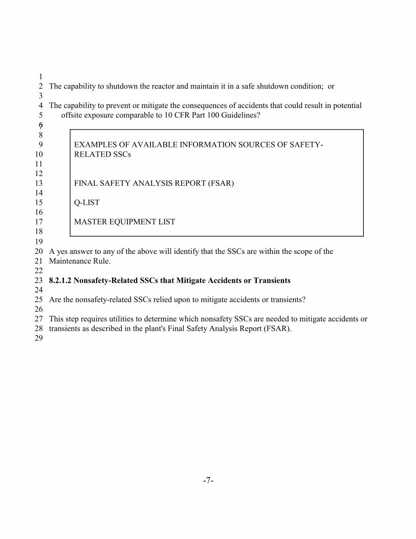
1The capability to shutdown the reactor and maintain it in a safe shutdown condition; or2
3The capability to prevent or mitigate the consequences of accidents that could result in potential4
offsite exposure comparable to 10 CFR Part 100 Guidelines?5678
EXAMPLES OF AVAILABLE INFORMATION SOURCES OF SAFETY-9RELATED SSCs10
1112
FINAL SAFETY ANALYSIS REPORT (FSAR)1314
Q-LIST1516
MASTER EQUIPMENT LIST171819
A yes answer to any of the above will identify that the SSCs are within the scope of the20Maintenance Rule.21
228.2.1.2 Nonsafety-Related SSCs that Mitigate Accidents or Transients23
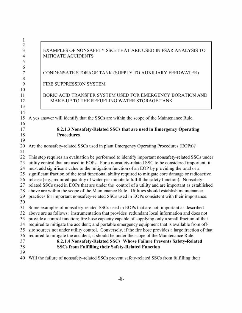
24Are the nonsafety-related SSCs relied upon to mitigate accidents or transients?25
26This step requires utilities to determine which nonsafety SSCs are needed to mitigate accidents or27transients as described in the plant's Final Safety Analysis Report (FSAR). 28
29
-8-
12
EXAMPLES OF NONSAFETY SSCs THAT ARE USED IN FSAR ANALYSIS TO3MITIGATE ACCIDENTS4
56
CONDENSATE STORAGE TANK (SUPPLY TO AUXILIARY FEEDWATER)78
FIRE SUPPRESSION SYSTEM910
BORIC ACID TRANSFER SYSTEM USED FOR EMERGENCY BORATION AND11MAKE-UP TO THE REFUELING WATER STORAGE TANK12
1314
A yes answer will identify that the SSCs are within the scope of the Maintenance Rule.1516
8.2.1.3 Nonsafety-Related SSCs that are used in Emergency Operating17Procedures18
19Are the nonsafety-related SSCs used in plant Emergency Operating Procedures (EOPs)?20
21This step requires an evaluation be performed to identify important nonsafety-related SSCs under 22utility control that are used in EOPs. For a nonsafety-related SSC to be considered important, it23must add significant value to the mitigation function of an EOP by providing the total or a24significant fraction of the total functional ability required to mitigate core damage or radioactive25release (e.g., required quantity of water per minute to fulfill the safety function). Nonsafety-26related SSCs used in EOPs that are under the control of a utility and are important as established27above are within the scope of the Maintenance Rule. Utilities should establish maintenance28practices for important nonsafety-related SSCs used in EOPs consistent with their importance.29
30Some examples of nonsafety-related SSCs used in EOPs that are not important as described31above are as follows: instrumentation that provides redundant local information and does not32provide a control function; fire hose capacity capable of supplying only a small fraction of that33required to mitigate the accident; and portable emergency equipment that is available from off-34site sources not under utility control. Conversely, if the fire hose provides a large fraction of that35required to mitigate the accident, it should be under the scope of the Maintenance Rule.36
8.2.1.4 Nonsafety-Related SSCs Whose Failure Prevents Safety-Related37SSCs from Fulfilling their Safety-Related Function38
39Will the failure of nonsafety-related SSCs prevent safety-related SSCs from fulfilling their40

7 The review of industry operating experience for scoping should include two refueling cycles or thirty-1
six months back from July 10, 1996.23
-9-
safety-related function?12
This step requires that each utility investigate the systems and system interdependencies to3determine failure modes of nonsafety-related SSCs that will directly affect safety-related4functions.5
6As used in this section of the guideline, the term "directly" applies to nonsafety-related SSCs:7
8Whose failure prevents a safety function from being fulfilled; or9
10Whose failure as a support SSC prevents a safety function from being fulfilled.11
12A yes answer identifies that the nonsafety-related SSCs are within the scope of the Maintenance13Rule.14
15A utility should rely on actual plant-specific and industrywide operating experience, prior16engineering evaluations such as PRA, IPE, IPEEE, environmental qualification (EQ), and 1017CFR 50 Appendix R analyses.18
19Industrywide operating experience is reviewed7 for plant-specific applicability and, where20appropriate, is included in utility specific programs and procedures. It is appropriate to use this21information to the extent practical to preclude unacceptable performance experienced in the22industry from being repeated. An event that has occurred at a similarly configured plant should23be considered for applicability to the reviewing utility.24
25The determination of hypothetical failures that could result from system interdependencies but26have not previously been experienced is not required. Failures subsequent to implementation of27this guideline shall be addressed in the determination of cause, corrective action, and28performance monitoring as described in Sections 8.0, 9.0 and 10.0.29
30

-10-
12
EXAMPLES OF NONSAFETY-RELATED SSCs WHOSE FAILURE PREVENTS3SAFETY-RELATED SSCs FROM FULFILLING THEIR SAFETY-RELATED4FUNCTION5
67
A NONSAFETY-RELATED INSTRUMENT AIR SYSTEM THAT OPENS8CONTAINMENT ISOLATION VALVES FOR PURGE AND VENT9
10A NONSAFETY-RELATED FIRE DAMPER IN STANDBY GAS TREATMENT11
SYSTEM WHOSE FAILURE WOULD IMPAIR AIR FLOW1213
IN SOME CASES THE CONDENSATE STORAGE TANK IS NOT SAFETY-14RELATED BUT IS A SOURCE OF WATER FOR ECCS15
16FAILURE OF A NONSAFETY SYSTEM FLUID BOUNDARY CAUSING LOSS17
OF A SAFETY SYSTEM FUNCTION (e.g., HEATING SYSTEM PIPING OVER18A SAFETY-RELATED ELECTRICAL PANEL)19
2021
8.2.1.5 Nonsafety-Related SSCs Whose Failure Causes a Reactor Scram or22Actuates Safety Systems23
24Has failure of the nonsafety related SSCs caused a reactor SCRAM or actuation of safety related25systems at your plant or a plant of similar design?26
27This step requires utilities to determine, on the basis of utility specific and industrywide28operating experience, those nonsafety related SSCs whose failure caused a reactor scram or29actuation of a safety related system. 30
31A yes answer identifies that the SSCs are within the scope of the Maintenance Rule.32
33A utility should rely on actual plant-specific and industrywide operating experience, prior34engineering evaluations such as PRA, IPE, IPEEE, environmental qualification (EQ), and 1035CFR 50 Appendix R analyses. 36
37

8 See footnote 7.12
-11-
Industrywide operating experience is reviewed8 for plant-specific applicability and, where1appropriate, is included in utility specific programs and procedures. It is appropriate to use this2information to the extent practical to preclude unacceptable performance experienced in the3industry from being repeated. An event that has occurred at a similarly configured plant should4be considered for applicability to the reviewing utility.5
6The determination of hypothetical failures that could result from system interdependencies but7have not been previously experienced is not required. Failures subsequent to implementation of8this guideline shall be addressed in the determination of cause, corrective action, and9performance monitoring as described in Sections 8.0, 9.0 and 10.0.10
111213
EXAMPLES OF FSAR NONSAFETY-RELATED COMPONENT TRANSIENT14INITIATORS15
1617
TURBINE TRIPS1819
LOSS OF FEEDWATER2021
LOSS OF INSTRUMENT AIR2223242526
EXAMPLES OF NONSAFETY-RELATED SSCs WHOSE FAILURE CAN CAUSE27A TRIP28
2930
TURBINE/GENERATOR3132
NON-ESF BUSSES THAT POWER REACTOR COOLANT PUMPS3334
ROD CONTROL SYSTEM SUCH THAT MULTIPLE RODS DROP INTO THE35CORE36
3738

-12-
12
EXAMPLE OF NONSAFETY-RELATED SSCs WHOSE FAILURE CAN CAUSE3ACTUATION OF A SAFETY SYSTEM4
56
RADIATION MONITOR (e.g., ISOLATES CONTROL ROOM VENTILATION)789
8.2.1.6 SSCs Outside the Scope of the Maintenance Rule1011
SSCs that do not meet the above criteria are outside the scope of the Maintenance Rule. These12SSCs will continue to have appropriate maintenance activities performed on them. For these13SSCs, the degree of maintenance attention will be dependent upon factors such as the14consequence of SSC failure on power production and economic importance.15
16
-13-
12
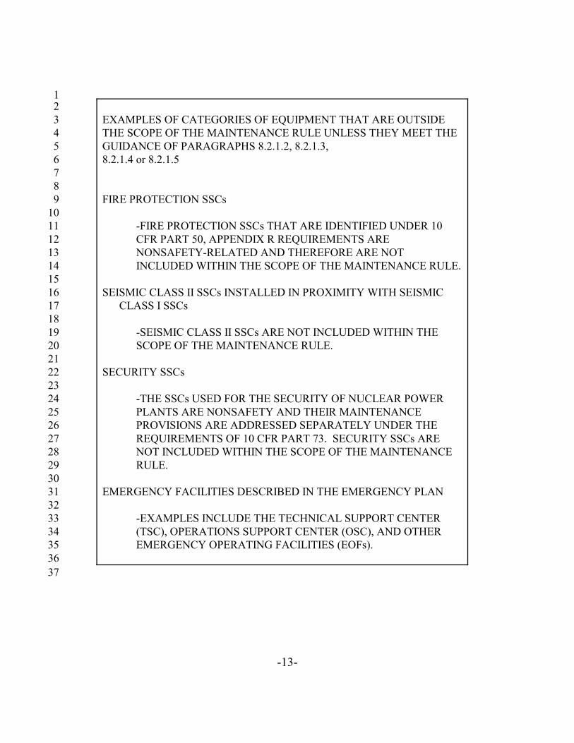
EXAMPLES OF CATEGORIES OF EQUIPMENT THAT ARE OUTSIDE3THE SCOPE OF THE MAINTENANCE RULE UNLESS THEY MEET THE4GUIDANCE OF PARAGRAPHS 8.2.1.2, 8.2.1.3, 58.2.1.4 or 8.2.1.56
78
FIRE PROTECTION SSCs910
-FIRE PROTECTION SSCs THAT ARE IDENTIFIED UNDER 1011CFR PART 50, APPENDIX R REQUIREMENTS ARE12NONSAFETY-RELATED AND THEREFORE ARE NOT13INCLUDED WITHIN THE SCOPE OF THE MAINTENANCE RULE.14
15SEISMIC CLASS II SSCs INSTALLED IN PROXIMITY WITH SEISMIC16
CLASS I SSCs1718
-SEISMIC CLASS II SSCs ARE NOT INCLUDED WITHIN THE19SCOPE OF THE MAINTENANCE RULE.20
21SECURITY SSCs22
23-THE SSCs USED FOR THE SECURITY OF NUCLEAR POWER24PLANTS ARE NONSAFETY AND THEIR MAINTENANCE25PROVISIONS ARE ADDRESSED SEPARATELY UNDER THE26REQUIREMENTS OF 10 CFR PART 73. SECURITY SSCs ARE27NOT INCLUDED WITHIN THE SCOPE OF THE MAINTENANCE28RULE.29
30EMERGENCY FACILITIES DESCRIBED IN THE EMERGENCY PLAN31
32-EXAMPLES INCLUDE THE TECHNICAL SUPPORT CENTER33(TSC), OPERATIONS SUPPORT CENTER (OSC), AND OTHER34EMERGENCY OPERATING FACILITIES (EOFs).35
3637
9.See definition.1
2
-14-
9.0 ESTABLISHING RISK AND PERFORMANCE CRITERIA/GOAL SETTING1AND MONITORING2
34
9.1 Reference56
10 CFR 50.65 (a)(1) 78
Each holder of an operating license under §§ 50.21 (b) or 50.22 shall monitor the performance or9condition of structures, systems, and components against licensee established goals, in a manner10sufficient to provide reasonable assurance that such structures, systems, and components, as11defined in paragraph (b), are capable of fulfilling their intended functions. Such goals shall be12established commensurate with safety and, where practical, take into account industry-wide13operating experience. When the performance or condition of a structure, system, or component14does not meet established goals, appropriate corrective action shall be taken.15
169.2 Guidance17
18Once the selection of those SSCs determined to be within the scope of the Maintenance Rule19(Section 8.0) has been completed, it is then necessary to establish risk significant and20performance9 criteria to initially determine which SSCs must have goals established and21monitoring activities performed in accordance with (a)(1). For SSCs that do not meet22performance criteria, a cause determination is performed and if appropriate goals are established23commensurate with an SSCs safety significance and performance. Monitoring the performance24of the SSCs against established goals is intended to provide reasonable assurance that the SSCs25are proceeding to acceptable performance.26
27All SSCs determined to be within the scope of the Maintenance Rule are subject to an effective28PM program as indicated by (a)(2) (see Section 10.0). SSCs that are within the scope of (a)(2)29could be included in the formal PM program, be inherently reliable (e.g., visual inspection during30walkdowns to meet licensee requirements that already exist), or be allowed to run to failure31(provide little or no contribution to system safety function). When SSCs in (a)(2) do not perform32acceptably, they are evaluated to determine the need for goal setting and monitoring under the33requirements of (a)(1).34
35

10 The following NUREGs describe other processes that could be used for this purpose: NUREG/CR-1
5424, "Eliciting and Analyzing Expert Judgment"; and NUREG/CR-4962, PLG-0533, "Methods for the2
Elicitation and Use of Expert Opinion in Risk Assessment."3
4
-15-
9.3 Determining the SSCs Covered by (a)(1)12
This section explains how to determine which SSCs that are under the scope of the Maintenance3Rule will have goals and monitoring established in accordance with (a)(1). Establishing both4risk significant criteria (Section 9.3.1) and performance criteria (Section 9.3.2) is necessary to5provide a standard to measure the performance of SSCs (Section 9.3.3).6
79.3.1 Establishing Risk Significant Criteria8
9Risk significant criteria should be established to determine which of the SSCs are risk10significant. Risk significant criteria should be developed using any of the following methods:11
12Individual Plant Examination (IPE),13
14Plant-specific Probabilistic Risk Assessment (PRA),15
16Critical safety functions (e.g., vessel inventory control) system performance review,17
18Other appropriately documented processes.1019
20Utilities may find the following sources provide useful data for monitoring risk significant SSC21performance:22
23Preventive Maintenance (PM) program results,24
25Evaluation of industrywide operating experience, or26
27Generic failure data.28
29Most of the methods described below identify risk significant SSCs with respect to core damage. 30It is equally important to identify as risk significant those SSCs that prevent containment failure31or bypass that could result in an unacceptable release. Examples might include the containment32spray system, containment cooling system, and valves that provide the boundary between the33reactor coolant system and low pressure systems located outside containment.34

-16-
Examples of risk determination methods are described in NUREG/CR-5695, "A Process for1Risk-Focused Maintenance." Other methods that can assist a utility in identifying risk significant2SSCs and enable appropriate maintenance prioritization and goal setting are included in: 3NUREG/CR-4550, "Analysis of Core Damage Frequency"; NUREG/CR-3385, "Measures of4Risk Importance"; NUREG/CR-5692, "Generic Risk Insights for General Electric Boiling Water5Reactors"; and NUREG/CR-5637, "Generic Risk Insights for Westinghouse and Combustion6Engineering Pressurized Water Reactors". In addition, the PSA Application Guide, EPRI Report7TR-105396(a) could be used as a reference source for establishing SSC risk significance.8
9Work done to date on symptom-based emergency operating procedures as well as IPE10vulnerability assessments may be used to establish risk significant criteria to screen SSCs, and to11select those SSCs required to fulfill a critical safety function.12
13An SSC could be risk significant for one failure mode and non risk significant for others. An14example of an SSC that is risk significant for one failure mode and non-risk significant for15another is as follows: Blowdown valves on steam generators perform a safety function to close16on isolation. However, the open position function is to maintain water chemistry which is a17nonsafety function. Additionally, many SSCs that are functionally important in modes other18than power operation, such as shutdown, may be identified by some normally employed analysis19methods (e.g., Engineering Analysis, IPE/PRA, etc.). These should be determined by an20assessment of their functional importance in other modes and a review of events and failures that21have occurred during these modes. 22
23Entry into a Technical Specification Limiting Condition for Operation, although important, is not24necessarily risk significant. 25
26Risk significant SSCs can be either safety-related or nonsafety-related. There are risk significant27systems that are in a standby mode and when called upon to perform a safety function, are28required to be available and reliable (e.g., high pressure coolant injection).29
30Another methodology that could be used to establish risk significance is a reliability approach to31maintenance. Plants which have completed reliability based maintenance assessments for any32systems that are risk significant could find data that supports the determination of SSCs33necessary to perform critical safety functions. These reliability assessments should indicate that34functional importance is considered for all plant modes, plant failure experience has been35reviewed and summarized, and potential failures have been identified and their likelihood36considered. A reliability based maintenance approach can also provide the basis for a preventive37maintenance activity, including component monitoring.38
39

-17-
Risk significant SSCs may be determined in accordance with a PRA similar to that used in1response to GL 88-20, "Individual Plant Examination for Severe Accident Vulnerabilities." The2assumptions developed for GL 88-20 could also be used in the calculation of the total3contribution to core damage frequency (CDF) and 10 CFR Part 100 type releases as a basis for4establishing plant-specific risk significant criteria.5
6If a utility selects a method based on PRA to establish risk significance, it should begin the7process by assembling a panel of individuals experienced with the plant PRA and with operations8and maintenance. The panel should utilize their expertise and PRA insights to develop the final9list of risk significant systems. NUREG/CR-5424 or NUREG/CR-4962 may be used as a10guideline in structuring the panel. The panel should review input from all three specific risk11importance calculational methods listed and described in Sections 9.3.1.1, 9.3.1.2 and 9.3.1.3 in12making its judgment regarding risk significant systems. It should be noted that each of these13methods will identify a different set of SSCs based upon differing concepts of importance. Each14method is useful in providing insights into risk significant SSC selection, and all of them should15be used in the decision making process.16
17Many currently used PRA software packages provide information on Fussell-Veseley Importance18and Risk Reduction Importance. Not all software includes techniques that utilize accident19sequence failure combinations (cut sets) and some adaptation of the software may be required to20appropriately establish risk significant SSCs. 21
22Utilities may use additional sensitivity methods (i. e., Birnbaum, Fussell-Veseley, etc.) if they23have been performed and are readily available. The use of additional computer software is not24required if the three methods (RRW, RAW, 90% CDF) have been performed. If additional25sensitivity methods are used an acceptable criteria (i.e., threshold) should be developed or the26expert panel could use the unprocessed information as a basis for determining risk significance.27
28The use of an expert panel would compensate for the limitations of PRA implementation29approaches resulting from the PRA structure (e.g., model assumptions, treatment of support30systems, level of definition of cut sets, cut set truncation, shadowing effect of very large (high31frequency) cut sets, and inclusion of repair or restoration of failed equipment) and limitations in32the meanings of the importance measures.33
34If desired by the utility, the expert panel may be used for additional functions. The expert panel,35or a similarly-established utility group could provide assistance in identifying SSCs that should36have goals established, review the periodic assessment, or provide insight on other elements of37the maintenance rule.38
39

11 Risk Reduction Worth is the decrease in risk if the SSC is assumed to be perfectly reliable for all1
failure modes (e.g., failure to start and failure to run). NUREG/CR-3385, "Measures of Risk Importance2
and their Applications."3
4
-18-
9.3.1.1 Risk Reduction Worth12
The following are two alternative methods for applying Risk Reduction Worth11 techniques in3the identification of risk significant SSCs. The two methods are similar, but the first normalizes4the Risk Reduction Worth by the sum of all maintenance related Risk Reduction Worths, while5the second uses Risk Reduction Worth compared to overall Core Damage Frequency. 6
7Method A: An SSC would probably be considered risk significant if its Risk Reduction8Importance Measure contributes to at least 99.0 percent of the cumulative Risk Reduction9Importance’s.10
11Specifically, risk significant SSCs can be identified by performing the following sequential steps:12
13Calculate the Risk Reduction Worth for the individual SSCs and rank in decreasing order.14
15Eliminate Risk Reduction Worths that are not specifically related to maintenance (e.g., operator16
error and external or initiating events).1718
Normalize the individual SSC Risk Reduction Worths by the sum of all the Risk Reduction19Worths related to maintenance. These are the Risk Reduction Importance Measures for the20individual SSCs, ranked by their contribution and expressed as a percentage.21
22SSCs that cumulatively account for about 99.0 percent of the sum of Risk Reduction23
Importance’s related to maintenance should be provided to the expert panel as an input in risk24determination.25
26Method B: Risk Reduction Worth may be used directly to identify risk significant SSCs. An27SSC would probably be considered risk significant if its Risk Reduction Worth exceeds 0.528percent of the overall Core Damage Frequency (Risk Reduction Worth >1.005). These may be29identified by performing the following sequential steps:30
31Calculate the Risk Reduction Worth for the individual SSCs and rank in decreasing order.32
33Eliminate Risk Reduction Worths that are not specifically related to maintenance (e.g., operator34
12 Risk Achievement Worth is the increase in risk if the SSC is assumed to be failed for all failure1
modes (e.g., failure to start and failure to run). NUREG/CR-3385, "Measures of Risk Importance and2
their Applications."3
4
-19-
error and external or initiating events).12
SSCs whose Risk Reduction Worth is > 0.5 percent of the overall Core Damage Frequency3should be provided to the expert panel as an input in risk determination.4
59.3.1.2 Core Damage Frequency Contribution6
7An SSC would probably be considered risk significant if it is included in cut sets that, when8ranked in decreasing order, cumulatively account for about 90 percent of the Core Damage9Frequency. 10
11Specifically, risk significant SSCs can be identified by performing the following sequential steps:12
13Identify the cut sets that account for about 90 percent of the overall Core Damage Frequency.14
15Eliminate cut sets that are not related to maintenance (e.g., operator error and external or16
initiating events).1718
SSCs that remain should be provided to the expert panel as an input in risk determination.1920
9.3.1.3 Risk Achievement Worth2122
An SSC would probably be considered risk significant if its Risk Achievement Worth12 shows at23least a doubling of the overall Core Damage Frequency and should be provided to the expert24panel as an input in risk determination.25
269.3.2 Performance Criteria for Evaluating SSCs27
28Performance criteria for evaluating SSCs are necessary to identify the standard against which29performance is to be measured. Criteria are established to provide a basis for determining30satisfactory performance and the need for goal setting. The actual performance criteria used31should be SSC availability, reliability, or condition.32
33The performance criteria could be quantified to a single value or range of values. For example, if34
-20-
a utility wanted to maintain an availability of 95 percent for a particular system because that was1the assumption used in the PRA, then the 95 percent value would be the performance criteria. If2the performance criteria are not met, then a goal could be set at a value equal to or greater than395 percent. Additionally, an example of condition as a performance criteria would be a case in4which a utility wanted to maintain the wall thickness of a piping system to comply with the5ASME code requirements. The utility would establish some acceptable value for wall thickness6and monitor by ultrasonic testing or other means.7
8If performance criteria are not met, the basis for the criteria should be reviewed to determine if9goal setting is required and the appropriate goal value established. It should be recognized that10while goals and performance criteria may have the same value and units, goals are only11established under (a)(1) where performance criteria are not being met and are meant to provide12reasonable assurance that the SSCs are proceeding to acceptable performance.13
14Specific performance criteria are established for all risk significant SSCs and for non-risk15significant SSCs that are in a standby (not normally operating) mode. Standby systems (either16risk significant or non risk significant and safety-related or nonsafety-related) may only affect a17plant level criteria if they fail to perform in response to an actual demand signal. This means that18a standby system could be failed but its inability to perform its intended function is not known19until it is required to perform in response to a demand signal or during testing (e.g., a20surveillance test to determine operability). The mode in which most standby system failures are21observed is during testing. Because plant transients occur less frequently, failure on demand22provides minimal information. For this reason, a plant level criteria is not a good indicator or23measurement of performance.24
25The performance criteria for a standby system can be qualitatively stated as "initiates upon26demand and performs its intended function." The reliability of a standby system to satisfy both27criteria can be quantitatively established as calculated in PRA methodology.28
29Plant level performance criteria are established for all remaining non-risk significant normally30operating SSCs. However, there may be some non-risk significant SSCs whose performance31cannot be practically monitored by plant-level criteria. Should this occur, other performance32criteria should be established, as appropriate (e.g., repetitions of safety function failures33attributable to the same maintenance-related cause).34
35All risk significant SSCs determined to have acceptable performance are placed in (a)(2) and36monitored against performance criteria established for risk significant SSCs. An example of the37process is as follows:38
39

-21-
SSC is determined to be in scope of Maintenance Rule; 12
SSC is determined to be risk significant;34
SSC performance criteria are established (e.g., the criteria could be an acceptable level of5reliability and availability/unavailability as appropriate.);6
7SSC performance is determined to meet the established criteria; and8
9SSC performance is monitored under (a)(2) against performance criteria established for risk10
significant SSCs.1112
Those non-risk significant SSCs that are in standby and have acceptable performance are also13addressed under (a)(2) and may be monitored by evaluating surveillance performance.14
15Risk significant SSCs and non-risk significant SSCs that are in standby that are determined to16have unacceptable performance, as defined in Section 9.3.4, are addressed under (a)(1), have17goals established, and performance monitored to those goals.18
19Remaining non-risk significant SSCs (those normally operating) are addressed under (a)(2) and20performance is monitored against plant level criteria. In the event a plant level performance21criteria is not met, a cause determination will be conducted to determine whether the failure of a22SSC within the scope of the maintenance rule was responsible and, if so, whether this failure was23an MPFF. In this case, the utility may address the SSC under (a)(1) and establish a goal and24monitor performance to that goal or continue to address performance under (a)(2) after taking25corrective action. The performance criteria selected should monitor what included it in the scope26of the maintenance rule. For example, automatic reactor scrams may be established as the27performance criteria that is to be monitored to demonstrate the effectiveness of preventive28maintenance for a given system.29
30If the function of the scoped system is lost and it causes a scram, the cause determination has to31be completed to determine if it is an MPFF. If it is, the MPFF has to be tracked. If a second32scram occurs that is caused by the same failure (i.e., repetitive) or a plant-level performance33criteria is not met, a goal has to be established; it may be established at the train or component34level. However, failures that do not cause a scram or actuation of a safety system do not have to35be tracked.36
37For example, Plant A has two 50 percent capacity circulating water pumps that provide cooling38to the condenser. Plant B has three 50 percent capacity circulating water pumps. Assuming loss39

13 The terms that follow are defined in Appendix B.1
2
-22-
of circulating water caused both reactors to scram, the system is within maintenance rule scope1for both Plant A and Plant B. If Plant A losses one pump it causes the plant to scram. However,2if Plant B experiences the loss of one pump, it does not cause a scram. Plant A is required to do3a cause determination to determine if it involves an MPFF. If it does, the failure that caused the4loss of the function that caused the unit to scram must be tracked. Plant B may elect to do a5cause determination but it is not required because a plant scram did not occur. In addition, if6Plant B experiences a second failure of the same type several weeks later and the unit does not7scram, it is not a repetitive failure. Neither failure on Plant B has to be addressed under the8maintenance rule because (1) the failure that occurred did not cause a loss of the function (i. e.,9total loss of cooling water that causes a scram) that scoped it within the maintenance rule and (2)10the plant-level performance criteria (i. e., unplanned automatic reactor scrams per 7000 hours11critical) was not affected.12
13Overall plant level performance criteria are broad based and are supported by many SSCs that14could be either safety or nonsafety-related. Since equipment performance is a major contributor15to meeting plant level performance criteria, it can be useful in determining maintenance program16effectiveness.17
18Plant level performance criteria should include, the following:1319
20Unplanned automatic reactor scrams per 7000 hours critical;21
22Unplanned safety system actuations; or23
24Unplanned capability loss factor25
26Other performance criteria may include indicators similar to those recognized by the NRC,27industry organizations, or established by the utility to monitor SSCs that cannot be practically28monitored by plant-level performance criteria.29
30Each utility should evaluate its own situation when determining the quantitative value for its 31individual plant level performance criteria. The determination of the quantitative value will be32influenced by different factors, including such things as design, operating history, age of the33plant, and previous plant performance.34
35Specific risk significant SSC performance criteria should consider plant-specific performance36

-23-
and, where practical, industrywide operating experience. Performance criteria for risk significant1SSCs should be established to assure that reliability and availability assumptions used in the2plant-specific PRA, IPE, IPEEE, or other risk determining analysis are maintained or adjusted3when determined necessary by the utility.4
5When establishing performance criteria for non-risk significant standby systems, surveillance6and actual system demands should be reviewed. Failures resulting from surveillances and valid7system actuations should be evaluated in accordance with Section 9.4.4.8
9
-24-
9.3.3 Evaluating SSCs Against Risk Significant and Performance Criteria12
After establishing SSCs that are within the scope of the Maintenance Rule and establishing the3risk significant and performance criteria, the next step is to evaluate the SSCs against the criteria. 4There are two phases in this evaluation.5
6In the first phase, SSCs are evaluated against the risk criteria (Section 9.3.1) to determine those7SSCs that are risk significant. For those SSCs that are risk significant, the associated SSC8specific performance criteria is established (Section 9.3.2). For those SSCs that are not risk9significant but are standby systems, the SSC specific performance criteria is established (Section109.3.2). For the remaining SSCs, the overall plant performance criteria applies.11
12The second phase is to evaluate the specific SSCs against the established performance criteria13using historical plant data, and industry data where applicable, to determine if the SSCs met the14performance criteria. The historical data used to determine the performance of SSCs consists of15that data for a period of at least two fuel cycles or 36 months, whichever is less. If the SSC16does not meet the established performance criteria, a cause determination is performed (Section179.4.4) to determine if the unacceptable performance was maintenance preventable (Section189.4.5). If the unacceptable performance was not maintenance preventable, the SSC is placed in19(a)(2) and addressed in the preventive maintenance program. If the corrective action has resolved20the issue, the SSC is placed in (a)(2). If it is determined that an acceptable trend in performance21is not demonstrated or the corrective action has not corrected the problem (Section 9.4.5), the22SSC is placed in (a)(1) and a goal is set (Section 9.3.4) for that SSC. If the trend of performance23indicates that the cause determination and corrective actions are effective, monitoring should be24continued until the goal is achieved.25
26If the SSC is determined to be inherently reliable, then it is not necessary to place the SSC in27(a)(1) and establish goals. As used here, an inherently reliable SSC is one that, without28preventive maintenance, has high reliability (e.g., jet shields, raceways). The need to place an29SSC under (a)(1) and establish goals may arise if the inherently reliable SSC has experienced a30failure. In such cases, the SSC cannot be considered inherently reliable.31
32SSCs that provide little or no contribution to system safety function could be allowed to run to33failure (i.e., perform corrective maintenance rather than preventive maintenance) and are34addressed by (a)(2).35
36As of July 10, 1996, the implementation date of the Maintenance Rule, all SSCs that are within37the scope of the Maintenance Rule will have been placed in (a)(2) and be part of the preventive38maintenance program. In addition, those SSCs with unacceptable performance will be placed in39

-25-
(a)(1) with goals established.12
After full implementation on July 10, 1996, those SSCs that have goals established will be3monitored (Section 9.4.2) using current plant data to determine if the goal is being met and if the4SSC can be placed in (a)(2).5
6For new plants with no operating history, the evaluation can be performed as follows. The utility7can place appropriate SSCs under paragraph (a)(1) of the maintenance rule, establish goals and8monitor those goals until an acceptable performance history has been determined. For SSCs not9designated (a) (1) the utility could utilize the performance history during pre-operational testing10and base SSC performance dispositioning on industry peer experience (e.g., NSSS plant of11similar design). Several determinations should be made including the following:12
13Design is similar enough to establish a baseline of performance.14
15Preventive maintenance programs of comparable plants are effective and the new plant has a16
basis for comparison.1718
Corrective action and cause determination methodology are effectively implemented to19identify and correct deficiencies.20
21Operating experience is shared between the comparable and new plant.22
23Process has been established at the new plant to evaluate lessons learned from the24
comparable plant.2526
For existing plants that have been shut down for extended periods (i. e., longer than one27operating cycle), the evaluation should take into account existing equipment operating history to28the maximum extent possible. However, where such data is not available or is out of date, the29utility should use information from sources described above for new construction.30
3132

-26-
9.3.4 Determining Whether an SSC Level Goal is Required12
If any of the following conditions exist, a goal should be established at the appropriate level (i.e.,3structure, system, train, or component):4
5A maintenance preventable functional failure (MPFF) caused an overall plant performance6
criteria to be exceeded (reference Section 9.4.5); or78
A MPFF caused a risk significant or non-risk significant SSC performance criteria not to be met;9or10
11A second MPFF (same cause) occurs following the initial MPFF and implementation of12
corrective action.1314
If the system or train level performance criteria or goal was not met as a result of a component's15MPFF, then the situation should be reviewed to determine if a goal should be established for the16component. If the cause of the component failure has been identified and the necessary17corrections made (e.g., replacement, redesign), a goal may not be needed unless it is a repetitive18MPFF.19
209.4 Goal Setting and Monitoring21
22Goals are established to bring about the necessary improvements in performance. When23establishing goals, a utility should consider various goal setting criteria such as existing industry24indicators, industry codes and standards, failure rates, duty cycles, and performance related data. 25In addition to the assumptions made in and results of reliability approaches to maintenance, the26assumptions in or results of IPEs/PRAs should also be considered when establishing goals. In27addition, analytical techniques (e.g., system unavailability modeling) may be considered for28developing goals. When selecting a goal, the data should be collected over a sufficient length of29time to minimize the effects of a random event.30
31Monitoring should consist of periodically gathering, trending, and evaluating information32pertinent to the performance, and/or availability of the SSCs and comparing the results with the33established goals and performance criteria to verify that the goals are being met. Results of34monitoring (including (a)(1) and (a)(2) activities) should be analyzed in timely manner to assure35that appropriate action is taken.36
37Regulations and utility commitments (e.g., Emergency Diesel Generator docketed reliability38targets in response to the Station Blackout Rule, 10 CFR 50.63) provide a baseline for testing and39

-27-
surveillance activities of some SSCs under the scope of the Maintenance Rule. Additional1testing and surveillance activities could be necessary if SSC performance is unacceptable. The2Maintenance Rule results could also provide the basis for reduced testing and surveillance. The3basis for technical specification, licensing commitments, and other regulation may be4appropriately used for goal setting. Typical examples of such regulations or licensee5commitments include:6
7Surveillance test and inspections performed in accordance with Section XI of the ASME code as8
required by 10 CFR 50.55a.910
Reactor pressure vessel material surveillance tests conducted in accordance with Appendix H of1110 CFR Part 50.12
13Containment leakage tests performed in accordance with Appendix J of 10 CFR Part 50.14
15Component surveillance or testing required by plant technical specifications.16
17Fire protection equipment tested and maintained in accordance with Appendix R of 10 CFR Part18
50.1920
Tests and inspections performed in response to NRC bulletins, generic letters, or information21notices.22
239.4.1 Goal Setting24
25Goals can be set at the structure, system, train, or component level, and for aggregates of these26where appropriate. In some cases the utility may elect to establish thresholds which would27provide indication of improved performance toward the ultimate goal. A quantitative value for a28goal or threshold may be established on the basis of judgment resulting from an appropriately29documented review of performance criteria (see Section 9.3.1). When setting a goal the utility30should take into account, where practical, industry-wide operating experience.31
329.4.1.1 System Level33
34For those SSCs requiring goal setting, it is expected that many goals will be established at the35system level. Where system level goals are to be established, system availability could be used36as the monitored parameter. Unavailability times for systems that support (e.g., service water,37HVAC, etc.) many systems can be accounted for by charging the time to the support system that38has failed and not the individual systems. Conversely, the unavailability times could be charged39

-28-
to both the support system (i.e., service water) and the supported system (i.e., diesel generator). 1The important factor is to ensure that the cause determination and corrective action are effective2and properly respond to correcting the problem regardless of how the unavailability times are3counted. A consistent approach is needed so that the performance criteria can be monitored and4tracked. Due to plant-specific redundancy and diversity, an SSC failure does not necessarily5cause a loss of safety function but could result in system or train performance that is6unacceptable.7
89.4.1.2 Train Level9
10Risk significant systems and standby systems that have redundant trains should have goals11established for the individual trains. The goal could be based on the availability desired or12assumed in the PRA analysis. Train level goals provide a method to address degraded13performance of a single train even though the system function is still available. The train level14goal should be set consistent with PRA or other methods of risk determination assumptions. 15Other alternative goal setting could consider the possibility of the best performing train to be16unavailable and the safety function reliability potentially reduced.17
189.4.1.3 Component Level19
20When component level goals are determined to be necessary, they should be established based21upon the component's contribution to a system not meeting its performance criteria or a system22level goal. Candidates for component goals could include classes of components with23unacceptable performance, components which have caused trips or are directly associated with24the causes of challenges to safety systems, and those components which have failed causing the25performance level or a goal at the system or train level to be missed. Careful review and analysis26should be performed prior to establishing component goals to ensure that the number of27component goals is manageable and not overly complex.28
299.4.1.4 Structure Level30
31It is expected that most structures will be addressed as required by (a)(2) of the Maintenance32Rule. In those cases where it is determined that a structure must have a goal established, the goal33could be based on, for example, limits for cracking, corrosion, erosion, settlement, deflection, or34other condition criteria.35
36
-29-
9.4.2 Monitoring123
Monitoring will be performed to determine if maintenance results in acceptable performance.45
If the plant specific safety analysis (i.e., FSAR) or PRA used to address a regulatory issue (e.g.,6IPEs) takes credit for any existing components in the system/train, then those components7supporting that function should be monitored under the maintenance rule. If credit is not taken,8they could be considered installed spare components which do not require monitoring under the9maintenance rule.10
11Monitoring SSCs against specific established goals should be conducted in a manner that12provides a means of recognizing performance trends. Where functional failures result in the13inability to meet performance criteria and could result in the loss of an intended maintenance rule14function, monitoring should be predictive, when appropriate, in order to provide timely warning. 15Monitoring should also provide a means for determining the effectiveness of previous corrective16actions.17
18Monitoring should appropriately consider the following factors:19
20Existing plant specific or industry performance monitoring such as technical specification21
surveillances, O&M Code, plant daily tours, ISI/IST and Appendix J test programs,22inspections and tests; 23
24Establishing a practical monitoring process (i.e., should not require extensive analytical modeling25
or excessive data collection) that is capable of detecting changes in SSC performance; and2627
Establishing a baseline to which the goals are monitored.2829
The monitoring frequency to meet established goals can vary, but may be initially established as30that currently required by existing surveillance requirements or other surveillance type31monitoring currently being performed. Frequency of monitoring is also dependent upon the goal32established and the availability of plant-specific or industry data. It may be either time directed,33or based on performance. The frequency of monitoring should be adjusted, if necessary, to allow34for early detection and timely correction of negative trends.35
36Data could be collected from existing sources (e.g., surveillances, Appendix J requirements,37ISI/IST, work order tracking) that are relevant to the goal being monitored. The type and quality38of the data being collected and trended is very important in that it will ultimately determine if39
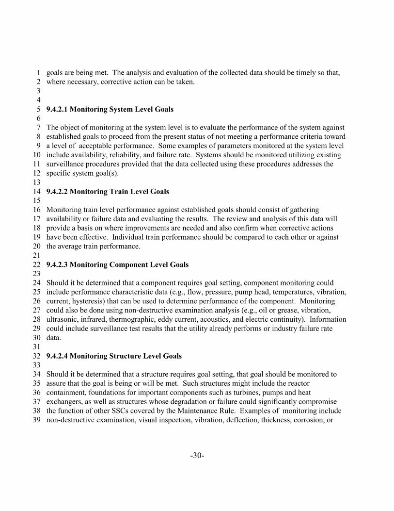
-30-
goals are being met. The analysis and evaluation of the collected data should be timely so that,1where necessary, corrective action can be taken.2
34
9.4.2.1 Monitoring System Level Goals56
The object of monitoring at the system level is to evaluate the performance of the system against7established goals to proceed from the present status of not meeting a performance criteria toward8a level of acceptable performance. Some examples of parameters monitored at the system level9include availability, reliability, and failure rate. Systems should be monitored utilizing existing10surveillance procedures provided that the data collected using these procedures addresses the11specific system goal(s).12
139.4.2.2 Monitoring Train Level Goals14
15Monitoring train level performance against established goals should consist of gathering16availability or failure data and evaluating the results. The review and analysis of this data will17provide a basis on where improvements are needed and also confirm when corrective actions18have been effective. Individual train performance should be compared to each other or against19the average train performance.20
219.4.2.3 Monitoring Component Level Goals22
23Should it be determined that a component requires goal setting, component monitoring could24include performance characteristic data (e.g., flow, pressure, pump head, temperatures, vibration,25current, hysteresis) that can be used to determine performance of the component. Monitoring26could also be done using non-destructive examination analysis (e.g., oil or grease, vibration,27ultrasonic, infrared, thermographic, eddy current, acoustics, and electric continuity). Information28could include surveillance test results that the utility already performs or industry failure rate29data.30
319.4.2.4 Monitoring Structure Level Goals32
33Should it be determined that a structure requires goal setting, that goal should be monitored to34assure that the goal is being or will be met. Such structures might include the reactor35containment, foundations for important components such as turbines, pumps and heat36exchangers, as well as structures whose degradation or failure could significantly compromise37the function of other SSCs covered by the Maintenance Rule. Examples of monitoring include38non-destructive examination, visual inspection, vibration, deflection, thickness, corrosion, or39
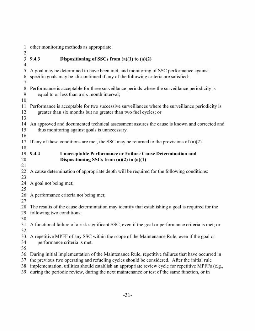
-31-
other monitoring methods as appropriate.12
9.4.3 Dispositioning of SSCs from (a)(1) to (a)(2)34
A goal may be determined to have been met, and monitoring of SSC performance against5specific goals may be discontinued if any of the following criteria are satisfied:6
7Performance is acceptable for three surveillance periods where the surveillance periodicity is8
equal to or less than a six month interval; 910
Performance is acceptable for two successive surveillances where the surveillance periodicity is11greater than six months but no greater than two fuel cycles; or12
13An approved and documented technical assessment assures the cause is known and corrected and14
thus monitoring against goals is unnecessary.1516
If any of these conditions are met, the SSC may be returned to the provisions of (a)(2).1718
9.4.4 Unacceptable Performance or Failure Cause Determination and19Dispositioning SSCs from (a)(2) to (a)(1)20
21A cause determination of appropriate depth will be required for the following conditions:22
23A goal not being met;24
25A performance criteria not being met;26
27The results of the cause determintation may identify that establishing a goal is required for the28following two conditions:29
30A functional failure of a risk significant SSC, even if the goal or performance criteria is met; or31
32A repetitive MPFF of any SSC within the scope of the Maintenance Rule, even if the goal or33
performance criteria is met.3435
During initial implementation of the Maintenance Rule, repetitive failures that have occurred in36the previous two operating and refueling cycles should be considered. After the initial rule37implementation, utilities should establish an appropriate review cycle for repetitive MPFFs (e.g.,38during the periodic review, during the next maintenance or test of the same function, or in39
-32-
accordance with Section 9.4.3).12
The cause determination should identify the cause of the failure or unacceptable performance,3and whether the failure was a MPFF (Section 9.4.5). It should identify any corrective action to4preclude recurrence, and make a determination as to whether or not the SSC requires (a)(1) goal5setting and monitoring (Section 9.3.4).6
7There are numerous techniques available to the utility industry that could be used to determine if8the failure is a MPFF. In some cases this determination is a simple assessment of an obvious9cause. In other cases the determination may require a rigorous and formal root cause analysis in10accordance with a methodology that exists in the industry. Any of these would be satisfactory11provided they result in identification and correction of the problem. 12
13Cause determination and corrective action should reinforce achieving the performance criteria or14goals that are monitored, and may also determine whether the performance criteria or goal itself15should be modified. A decision as to whether SSCs should have performance or goals monitored16should be made. The determination to allow failure may be an acceptable one. For example, a17decision to replace a failed component that provides little or no contribution to safety function18rather than performance of a preventive maintenance activity may reduce exposure,19contamination, and cost without impacting safety (see Section 10.2). Once the cause 20determination and corrective actions have been completed, the performance should continue to21be monitored and periodically evaluated until the performance criteria or goal is achieved.22
23The cause determination should address failure significance, the circumstances surrounding the24failure, the characteristics of the failure, and whether the failure is isolated or has generic or25common cause implications (refer to NUREG/CR 4780, "Procedures for Treating Common26Cause Failures in Safety and Reliability Studies," EPRI NP 5613). The circumstances27surrounding the failure may indicate that the SSC failed because of adverse operating conditions28(e.g., operating a valve dry, over-pressurization of system) or failure of another component which29caused the SSC failure. The results of cause determination should be documented for failures of30SSCs under the scope of the Maintenance Rule (Section 13).31
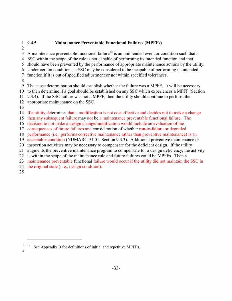
14 See Appendix B for definitions of initial and repetitive MPFFs.1
2
-33-
9.4.5 Maintenance Preventable Functional Failures (MPFFs)12
A maintenance preventable functional failure14 is an unintended event or condition such that a3SSC within the scope of the rule is not capable of performing its intended function and that4should have been prevented by the performance of appropriate maintenance actions by the utility. 5Under certain conditions, a SSC may be considered to be incapable of performing its intended6function if it is out of specified adjustment or not within specified tolerances.7
8The cause determination should establish whether the failure was a MPFF. It will be necessary9to then determine if a goal should be established on any SSC which experiences a MPFF (Section109.3.4). If the SSC failure was not a MPFF, then the utility should continue to perform the11appropriate maintenance on the SSC.12
13If a utility determines that a modification is not cost effective and decides not to make a change14then any subsequent failure may not be a maintenance preventable functional failure. The15decision to not make a design change/modification would include an evaluation of the16consequences of future failures and consideration of whether run-to-failure or degraded17performance (i.e., performs corrective maintenance rather than preventive maintenance) is an18acceptable condition (NUMARC 93-01, Section 9.3.3). Additional preventive maintenance or19inspection activities may be necessary to compensate for the deficient design. If the utility20augments the preventive maintenance program to compensate for a design deficiency, the activity21is within the scope of the maintenance rule and future failures could be MPFFs. Then a22maintenance preventable functional failure would occur if the utility did not maintain the SSC in23the original state (i. e., design condition).24
25

-34-
12
EXAMPLES OF MPFFs34
NOTE: "FUNCTIONAL" HAS BEEN ADDED TO PROVIDE EMPHASIS ON5ASSURING SAFETY FUNCTIONAL PERFORMANCE (INCLUDING FAILURES6THAT CAUSE SCRAMS) RATHER THAN ADDRESSING A DEFICIENCY THAT7DOES NOT AFFECT A SAFETY FUNCTION8
910
FAILURES DUE TO THE IMPLEMENTATION OF INCORRECT MAINTENANCE11PROCEDURES.12
13FAILURES DUE TO INCORRECT IMPLEMENTATION OF CORRECT14
MAINTENANCE PROCEDURES.1516
FAILURES DUE TO INCORRECT IMPLEMENTATION OF MAINTENANCE17PERFORMED WITHOUT PROCEDURES CONSIDERED WITHIN THE SKILL18OF THE CRAFT. 19
20FAILURES OF THE SAME KIND OCCURRING AT A UTILITY THAT HAVE21
OCCURRED IN INDUSTRY AS DEFINED BY INDUSTRY-WIDE22OPERATING EXPERIENCE THAT COULD HAVE BEEN PRECLUDED BY23AN APPROPRIATE AND TIMELY MAINTENANCE ACTIVITY.24
25FAILURES THAT OCCUR DUE TO THE FAILURE TO PERFORM26
MAINTENANCE ACTIVITIES THAT ARE NORMAL AND APPROPRIATE27TO THE EQUIPMENT FUNCTION AND IMPORTANCE. EXAMPLES28INCLUDE FAILURE TO LUBRICATE WITH THE APPROPRIATE29MATERIALS AT APPROPRIATE FREQUENCIES, FAILURE TO ROTATE30EQUIPMENT THAT IS IN A STANDBY MODE FOR LONG PERIODS. 31
32333435
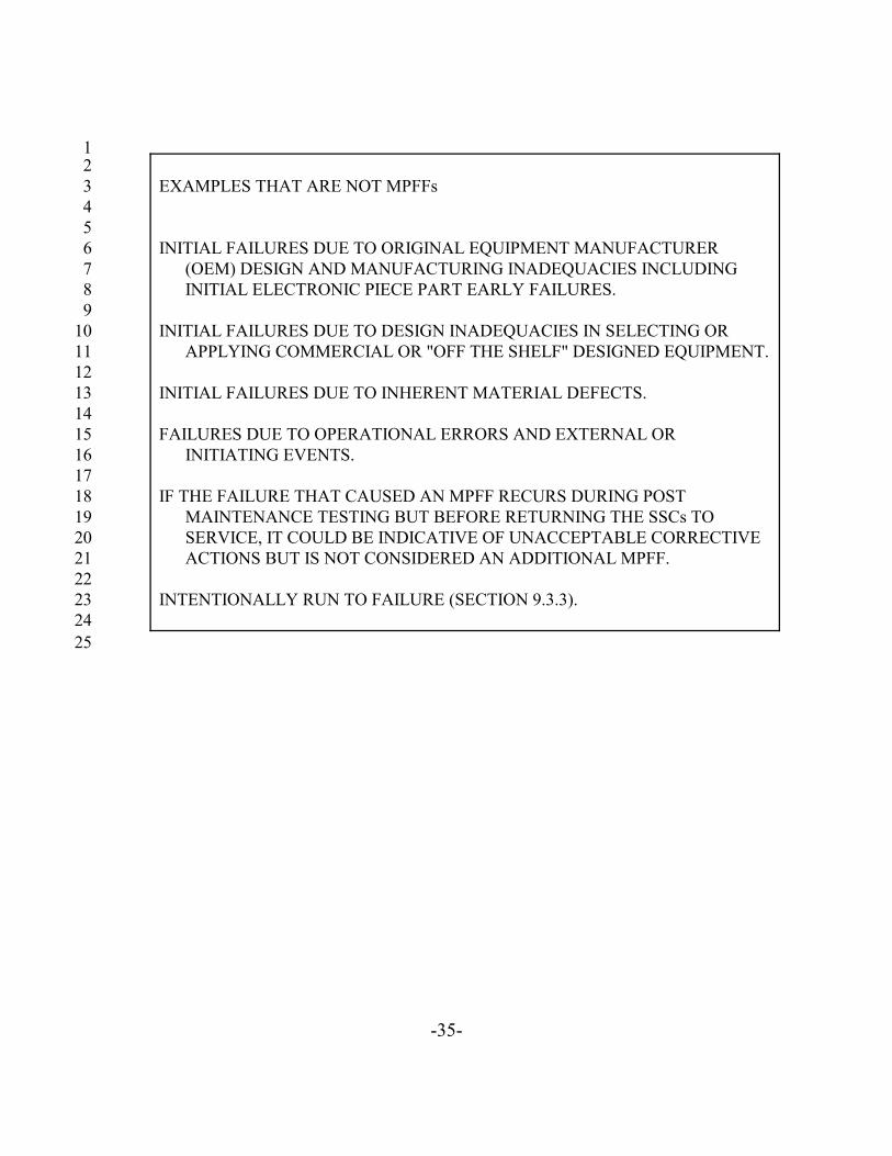
-35-
12
EXAMPLES THAT ARE NOT MPFFs345
INITIAL FAILURES DUE TO ORIGINAL EQUIPMENT MANUFACTURER6(OEM) DESIGN AND MANUFACTURING INADEQUACIES INCLUDING7INITIAL ELECTRONIC PIECE PART EARLY FAILURES.8
9INITIAL FAILURES DUE TO DESIGN INADEQUACIES IN SELECTING OR10
APPLYING COMMERCIAL OR "OFF THE SHELF" DESIGNED EQUIPMENT. 1112
INITIAL FAILURES DUE TO INHERENT MATERIAL DEFECTS.1314
FAILURES DUE TO OPERATIONAL ERRORS AND EXTERNAL OR15INITIATING EVENTS.16
17IF THE FAILURE THAT CAUSED AN MPFF RECURS DURING POST18
MAINTENANCE TESTING BUT BEFORE RETURNING THE SSCs TO19SERVICE, IT COULD BE INDICATIVE OF UNACCEPTABLE CORRECTIVE20ACTIONS BUT IS NOT CONSIDERED AN ADDITIONAL MPFF.21
22INTENTIONALLY RUN TO FAILURE (SECTION 9.3.3).23
2425

-36-
10.0 SSCs SUBJECT TO EFFECTIVE PREVENTIVE MAINTENANCE PROGRAMS123
10.1 Reference45
10 CFR 50.65 (a)(2)67
Monitoring as specified in paragraph (a)(1) of this section is not required where it has been8demonstrated that the performance or condition of a structure, system, or component is being9effectively controlled through the performance of appropriate preventive maintenance, such that10the structure, system, or component remains capable of performing its intended function.11
1210.2 Guidance13
14The methodology for implementing the Maintenance Rule by demonstrating maintenance15program effectiveness or inherent reliability in lieu of SSC goal setting is shown on the Industry16Guideline Implementation Logic Diagram (Figure 1). Although goals are set and monitored as17part of (a)(1), the preventive maintenance (PM) and performance monitoring activities are part18of (a)(2) and apply to all SSCs that are within the scope of the Maintenance Rule. SSCs that are19within the scope of (a)(2) could be included in the formal PM program, be inherently reliable20(e.g., visual inspection during walkdowns to meet licensee requirements that already exist), or be21allowed to run to failure (provide little or no contribution to system safety function).22
23An effective preventive maintenance program is one which will achieve the desired results of24minimizing component failures and increasing or maintaining SSC performance. The individual25maintenance program elements (training, procedures, cause determination, etc.) are focused and26directed toward achieving effective maintenance through appropriate use of resources.27
28If it can not be demonstrated that the performance of a SSC is being effectively controlled29through a PM program, then it is necessary to establish a goal and monitor the SSC's30performance against the goal.31
32If the SSC is determined to be inherently reliable, then it is not necessary to place the SSC in33(a)(1) and establish a goal. As used here, an inherently reliable SSC is one that, without34preventive maintenance, has high reliability (Section 9.3.3).35
36SSCs that provide little or no contribution to system safety function, therefore could be allowed37to run to failure (i.e., perform corrective maintenance rather than preventive maintenance) and38are addressed by (a)(2).39

-37-
10.2.1 Performance of Applicable Preventive Maintenance Activities12
Several methods are available to the industry for determining applicable and effective preventive3maintenance activities to ensure satisfactory performance of SSCs. It is not the intention of this4guideline to identify these programmatic methods of determining applicable maintenance5activities. Sound preventive maintenance activities include, but are not limited to, the following6elements:7
8Periodic maintenance, inspection, and testing;9
10Predictive maintenance, inspection, and testing;11
12Trending of appropriate failures.13
1410.2.1.1 Periodic Maintenance, Inspection, and Testing15
16Periodic maintenance, inspection, and testing activities are accomplished on a routine basis17(typically based on operating hours or calendar time) and include activities such as external18inspections, alignments or calibrations, internal inspections, overhauls, and component or19equipment replacement. Lubrication, filter changes, and teardown are some examples of20activities included in periodic maintenance.21
2210.2.1.2 Predictive Maintenance, Inspection, and Testing23
24Predictive maintenance activities, including performance monitoring, are generally non-intrusive25and can normally be performed with the equipment operating. Vibration analysis (includes26spectral analysis), bearing temperature monitoring, lube oil analysis (ferrography), infrared27surveys (thermography), and motor voltage and current checks are some examples of activities28included in predictive maintenance. The data obtained from predictive maintenance activities are29used to trend and monitor equipment performance so that planned maintenance can be performed30prior to equipment failure.31
32

-38-
10.2.1.3 Performance Trending12
Performance should be trended against established performance criteria so that adverse trends3can be identified. When adverse trends are identified, appropriate corrective action should be4promptly initiated. The utility's historical data, when combined with industry operating5experience, operating logs and records, and station performance monitoring data, can be useful in6analyzing trends and failures in equipment performance and making adjustments to the7preventive maintenance program.8
910.2.2 Ongoing Maintenance Effectiveness Evaluation10
11Ensuring satisfactory performance of risk significant and standby SSCs requires an ongoing12assessment against the utility's performance criteria (Section 9.3.3). The results of this13assessment should provide for feedback and adjustment of maintenance activities such that14MPFFs are addressed. MPFFs that are repetitive or risk significant must be investigated and the15cause determined (Section 9.4.4). When performance is determined to require improvement, the16utility should implement the appropriate corrective actions in a timely manner.17
18The objective of monitoring plant level performance criteria is to focus attention on the19aggregate performance of many of the operating SSCs covered by the scope of the Maintenance20Rule that are not individually risk significant.21
22There are no individual SSC performance criteria included in the plant level performance criteria. 23The SSCs that support plant level performance criteria are included in the preventive24maintenance program covered under (a)(2) of the Maintenance Rule. A failure of an individual25SSC may not result in unacceptable performance and may not affect a plant level performance26criteria. The utility may elect to establish a goal for the SSC that failed. If plant level27performance criteria were not met because of a MPFF, then the SSC should be considered for28disposition to (a)(1). See Sections 9.3.3 and 9.4 for elements to be considered.29
30This section is not intended to exclude a periodic review of preventive maintenance activities in31addition to the ongoing review to monitor maintenance effectiveness.32
3310.2.3 Monitoring the Condition of Structures34
35Structures can be monitored using performance criteria under (a)(2) (or goals under (a)(1)) of the36maintenance rule. These performance criteria (or goals) can be established to monitor either37performance or condition. For example, certain structures such as the primary containment can38be monitored through the performance of established testing requirements such as those39

-39-
contained in 10 CFR 50, Appendix J. Other structures such as reactor buildings, auxiliary1buildings, and cooling towers, may be more amenable to condition monitoring similar to that2performed as part of the inservice inspection (ISI) activities required by the ASME codes. Other3condition monitoring activities could include such activities as monitoring of corrosion,4settlement, roof leakage, concrete cracking, etc. Monitoring of structures should be given the5same priority as mechanical and electrical systems and components.6
7Utilities should establish performance criteria and goals under the maintenance rule which take8credit for, and if necessary build upon, the existing monitoring activities.9
10Monitoring of structures, like systems and components, should be predictive in nature and11provide early warning of degradation. The baseline condition of plant structures should be12established to facilitate condition monitoring activities. Although not required by regulations,13NUREG 1522, “Assessment of Safety-Related Structures in Nucleat Power Plants” provides14additional information on the subject.15
1617
-40-
11.0 EVALUATION OF SYSTEMS TO BE REMOVED FROM SERVICE123
11.1 Reference45
10 CFR 50.65(a)(3)67
In performing monitoring and preventive maintenance activities, an assessment of the total plant8equipment that is out of service should be taken into account to determine the overall effect on9performance of safety functions.10
1111.2 Guidance12
13This section provides guidance for the development of an approach to assess the impact on14overall plant safety functions upon removal of SSCs from service. The method is intended to15ensure that overall plant safety function capabilities are maintained. This guidance is intended to16cover all modes of plant operation.17
18The assessment does not require a quantitative assessment of probabilistic risk be performed. 19However, the quantitative assessment option can be used by a utility that has the capability. It20could take the form of guidelines for removing SSCs from service using a matrix approach, a21check list, a list of pre-analyzed configurations or some other utility specific approach. In those22cases where a pre-analyzed configuration, matrix or other approach does not address the23configuration the plant would be in to support the maintenance activity, additional considerations24or evaluations should be performed.25
26Additional guidelines for the removal of systems from service during plant shutdown are27included in NUMARC 91-06, Guidelines for Industry Actions to Assess Shutdown Management.28
29The development of an approach to assess the impact on overall plant safety functions upon30removal of SSCs from service consists of three steps:31
32Identify key plant safety functions to be maintained;33
34Identify SSCs that support key plant safety functions;35
36Consider the overall effect of removing SSCs identified above from service on key plant safety37
functions.3839
-41-
Steps 1 and 2 have been discussed in general terms in previous sections, and establish a1framework for the assessment of removing SSCs from service described in Step 3.2
311.2.1 Identify Key Plant Safety Functions Applicable to the Plant Design4
5Key plant safety functions are those that ensure the integrity of the reactor coolant pressure6boundary, ensure the capability to shut down and maintain the reactor in a safe shutdown7condition, and ensure the capability to prevent or mitigate the consequences of accidents that8could result in potential offsite exposure comparable to 10 CFR Part 100.9
10Examples of these are:11
12Containment Integrity (Containment Isolation, Containment Pressure and Temperature Control);13
14Reactivity Control;15
16Reactor Coolant Heat Removal; and17
18Reactor Coolant Inventory Control.19
20These functions are achieved by using systems or combinations of systems, that could include21redundant subsystems or trains. 22
2311.2.2 Identify SSCs That Support Key Plant Safety Functions24
25Once the required key plant safety functions are identified, the SSCs that support them need to be26identified (Section 8.2.1). The ability of a system to perform its intended function in support of27identified plant safety functions is key to determining the overall effect of taking SSCs out of28service.29
30Work done to date on symptom-based emergency operating procedures as well as IPE31vulnerability assessments can be used to establish risk significant criteria to identify SSCs and to32select those SSCs required to fulfill a key safety function.33
34
-42-
11.2.3 Assess and Control the Effect of the Removal of SSCs from Service on Key1Plant Safety Functions2
3During the planning and scheduling phase and prior to authorizing the removal of SSCs from4service, each planned maintenance activity that results in the removal of an SSC identified in5Section 11.2.2 from service should be assessed for its impact on key plant safety functions. This6assessment applies during all modes of plant operation and should take into account current plant7configuration as well as expected changes to plant configuration. 8
9For example, scheduling maintenance that requires auxiliary feedwater pumps being out of10service should take into account plant mode or condition, an assessment of when auxiliary11feedwater would be least needed, scheduled availability of other sources of feedwater, and the12time auxiliary feedwater would be unavailable. Additionally, prior to actually removing the13system from service to begin maintenance, the condition of the plant should be reviewed to verify14that conditions are acceptable to take the system out of service.15
16On-line maintenance is a planned and scheduled activity to perform preventive or corrective17maintenance, with the reactor at power, while properly controlling out-of-service time of systems18or equipment. The benefits of well managed maintenance conducted during power operations19include increased system and unit availability, reduction of equipment and system deficiencies20that could impact operations, more focused attention during periods when fewer activities are21competing for specialized resources, and reduction of work scope during outages. On-line22maintenance should be carefully managed to achieve a balance between the benefits and potential23impacts on safety, reliability or availability. For example, the margin of safety could be24adversely impacted if maintenance is performed on multiple equipment or systems25simultaneously without proper consideration of risk, or if operators are not fully cognizant of the26limitations placed on the plant due to out of service equipment. On-line maintenance should be27carefully evaluated, planned, and executed to avoid undesirable conditions or transients, and to28thereby ensure a conservative margin of core safety.29
30Insights gained from available operating experience and analytical tools (i. e., probabilistic safety31assessments) can be incorporated into the on-line maintenance process. Such insights can be32used to identify the systems or equipment that can be removed from service, considering33assessments of when the system would be least needed. These insights can also be used, where34appropriate, to establish specific criteria for use in making decisions about planned equipment35removal, frequency, and duration. Actions to manage risk generally are directed at properly36controlling out-of-service time and maintaining configuration control to ensure defense-in-depth37when certain systems or equipment are made unavailable.38
39
-43-
The decision to take equipment out of service for maintenance during power operation should1take into consideration the likelihood and possible consequences of an event occurring while the2equipment is out of service.3
4At each plant, a number of systems are identified as being risk significant and have performance5criteria established for allowable unavailability and reliability. For these systems, the6performance criteria is periodically evaluated to ensure that maintenance activities are effective7and result in high levels of system availability and reliability. The total time that a risk8significant system (or train) is out of service due to all causes (total unavailability) is monitored9against the performance criteria and controlled to avoid inadvertently increasing the risk of a10significant event.11
12

-44-
12.0 PERIODIC MAINTENANCE EFFECTIVENESS ASSESSMENTS123
12.1 Reference45
10 CFR 50.65 (a)(3)67
Performance and condition monitoring activities and associated goals and preventive8maintenance activities shall be evaluated at least every refueling cycle provided that the interval9between evaluations does not exceed 24 months. The evaluation shall be conducted taking into10account, where practical, industry-wide operating experience. Adjustment shall be made where11necessary to ensure that the objective of preventing failures of structures, systems, and12components through maintenance is appropriately balanced against the objective of minimizing13unavailability of structures, systems, and components due to monitoring or preventive14maintenance.15
1612.2 Guidance17
18Periodic assessments shall be performed to establish the effectiveness of maintenance actions. 19These assessments shall take into account, where practical, industrywide operating experience. 20The assessment consists of several activities to assure an effective maintenance program and to21identify necessary adjustments that should be made to the program. The periodic assessments,22cause determination, monitoring, and other activities associated with the Maintenance Rule23provide an opportunity to feedback lessons learned into the process. The following describes24some of the activities that should be performed.25
2612.2.1 Review of Goals (a)(1)27
28On a periodic basis goals established under (a)(1) of the Maintenance Rule shall be reviewed. 29The review should include an evaluation of the performance of the applicable SSCs against their30respective goals and should also evaluate each goal for its continued applicability. To31redisposition SSCs from (a)(1) to (a)(2), see Section 9.4.3.32
3312.2.2 Review of SSC Performance (a)(2)34
35On a periodic basis, SSC performance related to plant level criteria should be assessed to36determine maintenance effectiveness. The assessment should determine if performance is37acceptable. If performance is not acceptable, the cause should be determined and corrective38action implemented.39
-45-
For SSCs that are being monitored under (a)(2), the periodic assessment should include a review1of the performance against the established criteria. To redisposition SSCs from (a)(2) to (a)(1),2see Section 9.4.4.3
4Where appropriate, industrywide operating experience should be reviewed to identify potential5problems that are applicable to the plant. Applicable industry problems should be evaluated and6compared with the existing maintenance and monitoring activities. Where appropriate,7adjustments should be made to the existing programs.8
912.2.3 Review of Effectiveness of Corrective Actions10
11As part of the periodic review, corrective actions taken as a result of ongoing maintenance12activities or goal setting should be evaluated to ensure action was initiated when appropriate and13the action(s) taken resulted in improved performance of the SSC. Corrective actions that should14be reviewed include the following:15
16Actions to ensure that SSC performance meets goals established by requirements of (a)(1);17
18Actions taken as a result of cause determination as required in Section 9.3.3 or 10.2.2; and 19
20Status of problem resolution, if any, identified during the previous periodic assessment.21
2212.2.4 Optimizing Availability and Reliability for SSCs23
24For risk significant SSCs adjustments shall be made, where necessary, to maintenance activities25to ensure that the objective of preventing failures is appropriately balanced against the objective26of assuring acceptable SSC availability. For operating non-risk significant SSCs, it is acceptable27to measure SSC performance against overall plant performance criteria and for standby systems28to measure performance against specific criteria.29
30The intent is to optimize availability and reliability of the safety functions by properly managing31the occurrence of SSCs being out of service for preventive maintenance activities. This32optimization could be achieved by any of the following:33
34Ensuring that appropriate preventive maintenance is performed to meet availability objectives as35
stated in plant risk analysis, FSAR, or other reliability approaches to maintenance;3637
Allocating preventive maintenance to applicable tasks commensurate with anticipated38performance improvement (e.g., pump vibration analysis instead of teardown);39
-46-
1Reviewing to determine that availability of SSCs has been acceptable;2
3Focusing maintenance resources on preventing those failure modes that affect a safety function ;4
or56
Scheduling, as necessary, the amount, type, or frequency of preventive maintenance to7appropriately limit the time out of service.8
9The emergency diesel generator can be used as an example of optimizing reliability and10availability, (a)(3) and as an example of transitioning between the rule requirements specified in11(a)(1) and (a)(2) as follows:12
13If the Emergency Diesel Generator failed to meet its established performance criteria (Section149.3.3), a cause determination would be made as described in Section 9.4.4 of this guideline. 15Examples of performance criteria may include the target reliability value (i.e., 0.95 or 0.975) at a16level established in a utility's documented commitment from the Station Blackout Rule (SBO)17and unavailability that, if adopted as a performance criteria, would not alter the conclusions18reached in the utility IPE/PRA.19
20If a need for goal setting as described in Section 9.4 is indicated, an appropriate goal should be21established and monitored as indicated in (a)(1) until such time as the goal(s) are achieved and22monitoring can be resumed under (a)(2) as described in Section 9.4.3. Monitoring under (a)(1)23could be achieved by use of exceedance trigger values as described in Appendix D of NUMARC2487-00, Revision 1, dated August 1991, Guidelines and Technical Bases for NUMARC Initiatives25Addressing Station Blackout at Light Water Reactors, excluding those values indicated under26paragraph D.2.4.4 (Problem EDG).27
28The periodic assessment can be performed more frequently than the refueling cycle (e.g., on an29annual basis).30
31The periodic assessment does not have to be performed at any specific time during the refueling32cycle as long as it is performed at least one time during the refueling cycle, and the interval33between assessments does not exceed 24 months. This would allow utility’s at multiple unit sites34to perform the assessment at the same time even though the refueling cycles for the units are35staggered.36
37The requirements for performing the periodic assessment can be satisfied through the use of38ongoing assessments combined with a higher level summary assessment performed at least once39
-47-
per refueling cycle not to exceed 24 months between evaluations.12
The periodic assessment is intended to evaluate the effectiveness of (a)(1) and (a)(2) activities3including goals that have been established, monitoring of those established goals, cause4determinations and corrective actions, and the effectiveness of preventive maintenance5(including performance criteria). The periodic assessment may at the utilities option include the6balancing of availability and reliability, effectiveness of the process for removal of equipment7from service, and any other maintenance rule elements that would demonstrate the effectiveness8of maintenance.9
10
-48-
13.0 DOCUMENTATION123
13.1 General45
Documentation developed for implementation of this guideline is not subject to the utility quality6assurance program unless the documentation used has been previously defined as within the7scope of the quality assurance program. This documentation should be available for internal and8external review but is not required to be submitted to the NRC.9
1013.2 Documentation of SSC Selection Process11
12The SSCs that are identified for consideration under the provisions of the Maintenance Rule and13the criteria for inclusion shall be documented. SSC listings, functional descriptions, Piping and14Instrument Diagrams (P&IDs), flow diagrams, or other appropriate documents should be used for15this purpose.16
1713.2.1 Maintenance Rule Scoping18
19The following items from the initial scoping effort should be documented:20
21SSCs in scope and their function;22
23Performance criteria;24
25The SSCs placed in (a)(1) and the basis for placement, the goals established, and the basis for the26
goals; and2728
The SSCs placed in (a)(2) and the basis for (a)(2) placement.2930
Periodically, as a result of design changes, modifications to the plant occur that may affect the31maintenance program. These changes should be reviewed to assure the maintenance program is32appropriately adjusted in areas such as risk significance, goal setting, and performance33monitoring.34
3513.3 Documentation of (a)(1) Activities36
37Performance against established goals and cause determination results should be documented. 38Changes to goals including those instances when goals have been effective and the performance39

-49-
of the SSC has been improved to the point where the SSC can be moved to (a)(2) should be1documented. Monitoring and trending activities and actions taken as a result of these activities2should also be documented.3
413.4 Documentation of (a)(2) Activities5
6Activities associated with the preventive maintenance program should be documented consistent7with appropriate utility administrative procedures. For example, results of repairs, tests,8inspections, or other maintenance activities should be documented in accordance with plant9specific procedures. The results of cause determination for repetitive or other SSC failures that10are the result of MPFFs should be documented. Documentation of SSCs subject to ASME O&M11Code testing should be maintained. Evaluation of performance against plant level performance12criteria (Section 12.2.2) shall be documented. Adverse trends will be identified and those SSCs13affecting the trend will be investigated and, where appropriate, corrective action taken. 14
1513.5 Documentation of Periodic Assessment16
17The periodic assessment described above should be documented. Appropriate details or18summaries of results should be available on the following topics.19
20The results of monitoring activities for SSCs considered under (a)(1). The documentation should21
include the results of goals that were met;2223
Evaluation of performance criteria or goals that were not met, along with the cause24determinations and associated corrective actions taken;25
26Corrective actions for (a)(1) and (a)(2) that were not effective;27
28A summary of SSCs redispositioned from (a)(2) to (a)(1), and the basis;29
30A summary of SSCs redispositioned from (a)(1) to (a)(2), and the basis;31
32Identify changes to maintenance activities that result in improving the relationship of availability33
and preventive maintenance.3435

APPENDIX A12
THE NRC MAINTENANCE RULE34
A-1
APPENDIX A12
THE MAINTENANCE RULE34
2.A new § 50.65 is added to read as follows:56
§ 50.65 Requirements for monitoring the effectiveness of maintenance at nuclear power plants.78
(a)(1) Each holder of an operating license under §§ 50.21(b) or 50.22 shall monitor the9performance or condition of structures, systems, or components, against licensee-established10goals, in a manner sufficient to provide reasonable assurance that such structures, systems, and11components, as defined in paragraph (b), are capable of fulfilling their intended functions. Such12goals shall be established commensurate with safety and, where practical, take into account13industrywide operating experience. When the performance or condition of a structure, system or14component does not meet established goals, appropriate corrective action shall be taken.15
16(2)Monitoring as specified in paragraph (a)(1) of this section is not required where it has been17demonstrated that the performance or condition of a structure, system, or component is being18effectively controlled through the performance of appropriate preventive maintenance, such that19the structure, system, or component remains capable of performing its intended function.20
21(3)Performance and condition monitoring activities and associated goals and preventive22maintenance activities shall be evaluated at least every refueling cycle provided the interval23between evaluations does not exceed 24 months. The evaluation shall be conducted, taking into24account, where practical, industrywide operating experience. Adjustments shall be made where25necessary to ensure that the objective of preventing failures of structures, systems, and26components through maintenance is appropriately balanced against the objective of minimizing27unavailability of structures, systems, and components due to monitoring or preventive28maintenance. In performing monitoring and preventive maintenance activities, an assessment of29the total plant equipment that is out of service should be taken into account to determine the30overall effect on performance of safety functions.31
32(b) The scope of the monitoring program specified in paragraph (a)(1) of this section shall33include safety-related and nonsafety related structures, systems, and components, as follows:34
35(1)Safety-related structures, systems, or components that are relied upon to remain functional36

A-2
during and following design basis events to ensure the integrity of the reactor coolant pressure1boundary, the capability to shut down the reactor and maintain it in a safe shutdown condition,2and the capability to prevent or mitigate the consequences of accidents that could result in3potential offsite exposure comparable to the 10 CFR part 100 guidelines.4
5(2)Nonsafety related structures, systems, or components:6
7(i)That are relied upon to mitigate accidents or transients or are used in plant emergency8operating procedures (EOPs); or 9
10(ii)Whose failure could prevent safety-related structures, systems, and components from fulfilling11their safety-related function; or12
13(iii)Whose failure could cause a reactor scram or actuation of a safety-related system.14
15(c)The requirements of this section shall be implemented by each licensee no later than July 10,161996.17
18Dated at Rockville, Maryland, this 28th day of June, 1991.19
20For the Nuclear Regulatory Commission.21
22Samuel J. Chilk,23Secretary of the Commission.24
25[FR Doc. 91-16322 Filed 7-9-91; 8:45 a.m.]26
27Billing Code 7590-01-M28
29

APPENDIX B12
MAINTENANCE GUIDELINE DEFINITIONS34
B-1
APPENDIX B1MAINTENANCE GUIDELINE DEFINITIONS2
3Availability:4
5The time that a SSC is capable of performing its intended function as a fraction of the total time6that the intended function may be demanded. The numerical complement of unavailability.7
89
Cut Sets:1011
Accident sequence failure combinations.1213
Function:1415
As used in this guideline the scoped function is that attribute (e.g., safety related, mitigates16accidents, causes a scram, etc.) that included the SSC within the scope of the maintenance rule. 17For example, some units scope the condenser vacuum system under the maintenance rule because18its total failure caused a scram and not the design function of pulling a vacuum on the condenser.19
20Industrywide Operating Experience (including NRC and vendor):21
22Information included in NRC, industry, and vendor equipment information that are applicable23and available to the nuclear industry with the intent of minimizing adverse plant conditions or24situations through shared experiences.25
2627
Maintenance:2829
The aggregate of those functions required to preserve or restore safety, reliability, and availability30of plant structures, systems, and components. Maintenance includes not only activities31traditionally associated with identifying and correcting actual or potential degraded conditions,32i.e., repair, surveillance, diagnostic examinations, and preventive measures; but extends to all33supporting functions for the conduct of these activities. (Source: Federal Register Vol. 53, No.3456, Wednesday, March 23, 1988, Rules and Regulations/ Page 9340).35
36
B-2
Maintenance, Preventive:12
Predictive, periodic, and planned maintenance actions taken prior to SSC failure to maintain the3SSC within design operating conditions by controlling degradation or failure.4
56
Maintenance Preventable Functional Failure (MPFF)- Initial and Repetitive78
An MPFF is the failure of an SSC (structure, system, train, or component) within the scope of the9Maintenance Rule to perform its intended function (i.e., the function performed by the SSC that10required its inclusion within the scope of the rule), where the cause of the failure of the SSC is11attributable to a maintenance-related activity. The maintenance-related activity is intended in the12broad sense of maintenance as defined above.13
14The loss of function can be either direct, i.e., the SSC that performs the function fails to perform15its intended function or indirect, i.e., the SSC fails to perform its intended function as a result of16the failure of another SSC (either safety related or nonsafety related).17
18An initial MPFF is the first occurrence for a particular SSC for which the failure results in a loss19of function that is attributable to a maintenance related cause. An initial MPFF is a failure that20would have been avoided by a maintenance activity that has not been otherwise evaluated as an21acceptable result (i.e., allowed to run to failure due to an acceptable risk).22
23A "repetitive" MPFF is the subsequent loss of function (as defined above) that is attributable to24the same maintenance related cause that has previously occurred (e.g., an MOV fails to close25because a spring pack was installed improperly -- the next time this MOV fails to close because26the spring pack is installed improperly: the MPFF is repetitive and the previous corrective action27did not preclude recurrence). A second or subsequent loss of function that results from a28different maintenance related cause is not considered a repetitive MPFF (e.g., an MOV initially29fails to close because a spring pack was installed improperly -- the next time it fails to close, its30failure to close is because a set screw was improperly installed: the MPFF is not repetitive).31
32During initial implementation of the Maintenance Rule, repetitive failures that have occurred in33the previous two operating and refueling cycles should be considered. After the initial rule34implementation, utilities should establish an appropriate review cycle for repetitive MPFFs (i.e.,35during the periodic review, during the next maintenance or test of the same function, or in36
B-3
accordance with Section 9.4.3).123
Monitoring Performance:45
Continuous or periodic tests, inspections, measurement or trending of the performance or6physical characteristics of an SSC to indicate current or future performance and the potential for7failure. Monitoring is frequently conducted on a non-intrusive basis. Examples of preventive8maintenance actions may include operator rounds, engineering walkdowns, and management9inspections.10
1112
Operating System:1314
An operating system is one that is required to perform its intended function continuously to15sustain power operation or shutdown conditions.16
17The system function may be achieved through the use of redundant trains (i.e. two redundant18independent trains each with a motor driven pump capable of delivering 100% capacity to each19train). In this case, either train using either pump will be capable of performing the system20function. 21
22Normal operation would be with one train operating and one train in standby (not operating). 23The train in standby (not operating) would normally be capable of starting and providing the24system function if the train that was in operation failed. In this case, if the function of the25operating train is lost, and the standby (non-operating) train starts and maintains the system26function with no perturbation of plant operation, then there is no loss of system function. The27performance criteria for this type of system should include both the operational and standby (not28operating) performance characteristics as applicable.29
30In the case where a system with redundant trains has a diverse system (i.e. a steam driven pump31and piping, valves, etc.) that will perform the same function, it is possible to lose both trains of32the redundant system and still maintain system function with the diverse system. Performance33criteria should be established for the diverse system based on its individual performance taking34into account its diverse method of performing the required function, its unique configuration and35any other functions related that it performs as related to the Maintenance Rule.36

B-4
1Performance:2
3Performance when used in the context for criteria and monitoring would include availability and4reliability and/or condition as appropriate. To the maximum extent possible both availability and5reliability should be used since that provides the maximum assurance that performance is being6monitored. There are instances (i.e., reactor coolant system, electrical load centers, certain7standby equipment, etc.) where availability does not provide a meaningful measure of8performance and should not be captured. The condition of structures is more appropriate to9monitor than the reliability or availability. The monitoring of individual components (e.g.,10unacceptable performance) when setting goals may include the monitoring of condition. 11Condition typically includes vibration, flow, temperature and other similar parameters.12
1314
Reliability:1516
A measure of the expectation (assuming that the SSC is available) that the SSC will perform its17function upon demand at any future instant in time. The monitoring of performance and any18resulting MPFFs is an indicator of reliability.19
2021
Risk:2223
Risk encompasses what can happen (scenario), its likelihood (probability), and its level of24damage (consequences).25
2627
Risk Significant SSCs:2829
Those SSCs that are significant contributors to risk as determined by PRA/IPE or other methods.303132
Standby System or Train3334
A standby system or train is one that is not operating and only performs its intended function35when initiated by either an automatic or manual demand signal. 36
B-5
Some of these systems perform a function that may be required intermittently during power1operations (e.g., a process system used to adjust or correct water chemistry). Although not2continuously operating the system or one of its trains must be able to actuate on a manual or3automatic signal and be able to perform its intended function as required. Since the system or4train is in the standby mode, it will most frequently be determined as operable/inoperable during5operability (surveillance) testing, although if designed to actuate automatically, it could fail on6demand. Based on experience and the reason for performing surveillance testing the best way to7measure the performance of the standby system is based on the results of performance on demand8(both an automatic response to a valid signal and as a result of surveillance testing). Examples of9standby systems of this type would be the hydrogen recombiner system and the containment10spray system.11
12Other systems and their associated trains may be configured in a standby mode during power13operation but during an outage are normally operating (e.g., RHR). Performance monitoring14should consider the system function during all plant modes.15
16System17
18A collection of equipment that is configured and operated to serve some specific plant19function(s) (e.g., provides water to the steam generators, sprays water into the containment,20injects water into the primary system), as defined by the terminology of each utility (e.g.,21auxiliary feedwater system, containment spray system, high pressure coolant injection system). 22The system definition should generally be consistent with the system definition in the FSAR or23PRA analysis.24
25Train26
27A collection of equipment that is configured and operated to serve some specific plant safety28function and may be a sub-set of a system. The utility can utilize the FSAR or PRA analysis to29better define the intended configuration and function(s).30
3132
Unavailability, SSC (for purposes of availability or reliability calculation):3334
The numerical complement of availability. An SSC that cannot perform its intended function. 35An SSC that is required to be available for automatic operation must be available and respond36

B-6
without human action.123
Unplanned Automatic Scrams per 7,000 Hours Critical45
This indicator tracks the average scram rate per 7,000 hours of reactor criticality (approximately6one year of operation) for units operating with more than 1,000 critical hours during the year. 7Unplanned automatic scrams result in thermal/hydraulic transients in plant systems.8
910
Unplanned Capability Loss Factor:1112
Unplanned capability loss factor is the percentage of maximum energy generation that a plant is13not capable of supplying to the electrical grid because of unplanned energy losses (such as14unplanned shutdowns, forced outages, outage extensions or load reductions). Energy losses are15considered unplanned if they are not scheduled at least four weeks in advance.16
1718
Unplanned Safety System Actuations1920
Unplanned safety system actuations include unplanned emergency core cooling system actuations21or emergency AC power system actuations due to loss of power to a safeguards bus.22
2324

APPENDIX C12
MAINTENANCE GUIDELINE ACRONYMS34

C-1
12
CFR Code of Federal Regulation34
EOP Emergency Operating Procedures56
FSAR Final Safety Analysis Report78
IPE Individual Plant Evaluations910
ISI Inservice Inspection1112
IST Inservice Testing1314
MPFF Maintenance Preventable Functional Failures1516
NRC Nuclear Regulatory Commission1718
NUMARC Nuclear Management and Resources Council1920
P&ID Piping and Instrument Diagrams2122
PRA Probabilistic Risk Assessment2324

123456789
101112131415
APPENDIX D1617
EXAMPLE OF A SYSTEM WITH BOTH SAFETY AND18NONSAFETY FUNCTIONS - CVCS19
20

D-1
APPENDIX D1EXAMPLE OF A SYSTEM WITH BOTH SAFETY AND NONSAFETY FUNCTIONS -2CVCS3
4Note: This example is for illustration purposes only and is not intended to be definitive for any5given plant. Each utility should examine its own design and operation for applicability.6
7The typical Chemical and Volume Control System (CVCS), shown in the attached figure, has8many functions such as: adjust the concentration of boric acid, maintain water inventory, provide9seal water to the reactor coolant pump seals, process reactor coolant effluent for reuse, maintain10proper chemistry concentration, and provide water for high pressure safety injection. Clearly, the11high pressure safety injection function of the CVCS is encompassed by the description in (b)(1)12of 10 CFR 50.65 and therefore, within the scope of the rule. Other components and functions of13the CVCS such as the regenerative heat exchanger, the letdown heat exchanger, the mixed bed14demineralizers, the volume control tank and their associated valves and control systems which15function to maintain inventory, process coolant and maintain chemistry, do not generally have16safety functions. These portions of the CVCS do not typically meet the descriptions in (b)(1) or17(2) of 10 CFR 50.65 and would not be considered within the scope of the rule. Components18within these portions of the CVCS, however, may fit the descriptions in (b)(1) or (b)(2). 19Examples of this would be the volume control tank isolation valves which close to align the20system for high pressure injection and the various valves which also serve as containment21isolation valves. Other portions of the CVCS would need to be examined closely to determine22whether they meet the descriptions in (b)(1) or (b)(2). For example, the seal injection portion of23CVCS may be within the scope if the reactor coolant pumps are relied upon in transients or24EOPs, or if the failure of seal injection could cause a scram or actuation of a safety-related25system.26