Embed Size (px)
Citation preview
ATTACHMENT-A
Technical Specifications
1. SCOPE OF SUPPLY
2. REMARKS
3. SPECIAL INSTRUCTIONS TO BIDDER
4. TESTING & INSPECTION
5. TEST OF SKID EQUIPMENT/INSTRUMENT
6. INFORMATION/ DOCUMENTS/ DRWGS TO BE SUBMITTED BY SUCCESSFUL BIDDER
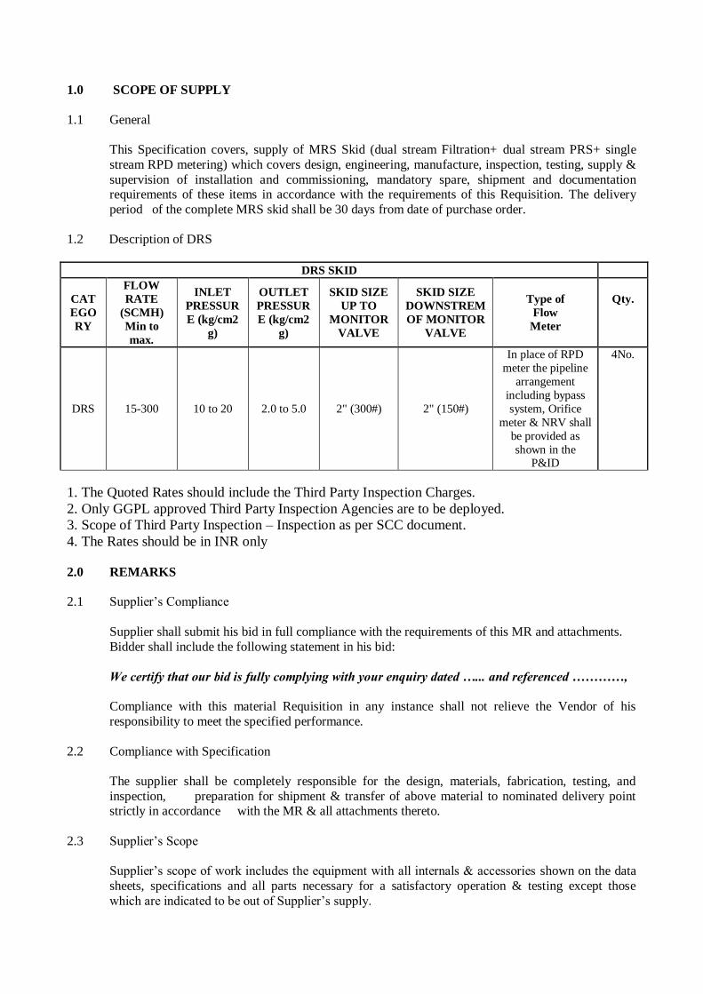
1.0 SCOPE OF SUPPLY
1.1 General
This Specification covers, supply of MRS Skid (dual stream Filtration+ dual stream PRS+ single
stream RPD metering) which covers design, engineering, manufacture, inspection, testing, supply &
supervision of installation and commissioning, mandatory spare, shipment and documentation requirements of these items in accordance with the requirements of this Requisition. The delivery
period of the complete MRS skid shall be 30 days from date of purchase order.
1.2 Description of DRS
DRS SKID
CAT
EGO
RY
FLOW
RATE
(SCMH)
Min to
max.
INLET
PRESSUR
E (kg/cm2
g)
OUTLET
PRESSUR
E (kg/cm2
g)
SKID SIZE
UP TO
MONITOR
VALVE
SKID SIZE
DOWNSTREM
OF MONITOR
VALVE
Type of
Flow
Meter
Qty.
DRS 15-300 10 to 20 2.0 to 5.0 2" (300#) 2" (150#)
In place of RPD
meter the pipeline
arrangement
including bypass
system, Orifice
meter & NRV shall
be provided as
shown in the P&ID
4No.
1. The Quoted Rates should include the Third Party Inspection Charges.
2. Only GGPL approved Third Party Inspection Agencies are to be deployed.
3. Scope of Third Party Inspection – Inspection as per SCC document.
4. The Rates should be in INR only
2.0 REMARKS
2.1 Supplier’s Compliance
Supplier shall submit his bid in full compliance with the requirements of this MR and attachments.
Bidder shall include the following statement in his bid:
We certify that our bid is fully complying with your enquiry dated …... and referenced …………,
Compliance with this material Requisition in any instance shall not relieve the Vendor of his
responsibility to meet the specified performance.
2.2 Compliance with Specification
The supplier shall be completely responsible for the design, materials, fabrication, testing, and
inspection, preparation for shipment & transfer of above material to nominated delivery point strictly in accordance with the MR & all attachments thereto.
2.3 Supplier’s Scope
Supplier’s scope of work includes the equipment with all internals & accessories shown on the data
sheets, specifications and all parts necessary for a satisfactory operation & testing except those
which are indicated to be out of Supplier’s supply.
2.4 Inspection
Supplier shall submit with his bid a list of 3 well known international Third Party inspection Agencies for owner approval, which he intends to use for inspection. This agency will issue all
relevant certificates as per specification & codes.
Inspection shall also be performed by a designated Third Party Inspection agency and/or owner as
set out & specified in the codes & particular documents forming this MR.
3.0 SPECIAL INSTRUCTIONS TO BIDDERS
3.1 Bidder to note that no correspondence shall be entered into or entertained after the bid submission.
3.2 Bidder shall furnish quotation only in case he can supply material strictly as per this Material
Requisition and specification/data sheets forming part of Material Requisition.
3.3 If the offer contains any technical deviations or clarifications or stipulates any technical
specifications (even if in line with MR requirements) and does not include complete scope &
technical/ performance data required to be submitted with the offer, the offer shall be liable for rejection.
3.4 The submission of prices by the Bidder shall be construed to mean that he has confirmed compliance
with all technical specifications of the corresponding item(s).
3.5 Supplier must note that stage wise inspection for complete fabrication, testing including raw material
inspection to be carried out.
3.5.1 Vendors for bought out items to be restricted to the approved vendor list attached with Bid
document. Approval of additional vendor if required, for all critical bought out items shall be
obtained by the supplier from the purchaser before placement of order. Credentials/ PTR of the additional vendor proposed to be submitted by supplier for review and approval of Purchaser/
Purchaser’s representative.
3.5.2 The Skid manufacturer must deliver a Certificate of 3.1(b) stating the quality, the mechanical
properties, the chemical analysis the process of manufacture and the making for the skid (MRS).
3.6 All material shall be delivered at Company’s designated storage yard. The destination for delivery of
items is given in Commercial Section of the tender.
3.6.1 Testing & calibration of all instruments, Factory Acceptance Test (FAT) and Site acceptance Test (SAT) shall be carried out by the bidder. Range/ calibration span, set points, reports etc shall be
modified as per Owner’s requirement by the bidder during FAT and SAT. Owner shall witness
testing of any or all items at various stages during manufacture and/or at final stage before shipment at their discretion. Testing shall be carried out as per approved procedures. No
instrument shall leave manufacturer’s works without factory acceptance test. All necessary changes
shall be incorporated/ implemented as suggested by owner during FAT/ SAT etc. As build drawing,
final technical documentation shall be submitted by the bidder. It shall contain all such changes.
3.7 Testing & Calibration:
Bidder’s scope of work includes testing of all supplied items and systems including impulse lines,
pneumatic signal tubes and instrument cables and special instruments/ items if any. Bidder shall also
carryout testing and calibration of all instruments as per the requirements specified elsewhere in
tender document. Testing and calibration of Gas metering system shall be as described elsewhere in the document.
3.8 Commissioning:
It is the responsibility of Bidder to co-ordinate and make available the services of vendors/ sub-
vendors for gas metering system package, control system, etc. and other special instruments/ equipment like Gas flow meters, Flow computers, Pressure regulators, testing, FAT, Site
acceptance, start-up/ commissioning of the station. The bidder shall provide assistance during
commissioning without any condition/ pre-requisite. It is the responsibility of the bidder to get the certification from site Engineer.
3.8.1 Electronic Volume corrector (EVC) with solar panel shall be required for RPD meter type metering
skid. The system shall be designed in such a way that it should operate through battery. Bidder shall
submit Product Technical Literature along with offer.
3.8.2 Lifting lugs and spreader beam / frame, foundation Anchor bolts, copper jumpers for flanges for the
skid, Stainless steel nameplate for each tagged equipment and component; All Tie-ins with flanged
connections shall be in bidder’s scope. Earth bonding system and earthing boss for skid are in
bidder’s scope. Inlet and Outlet matching flanges and Studs &nuts (for skid interconnection and Inlet
& Outlet piping connection), suitable Gaskets shall also be supplied along-with each skid.
3.8.3 Bidder to provide licensed Software in the name of owner for authenticating the algorithm written in
the EVC as per AGA.
3.8.4 Bidder to provide the necessary hardware/ software (licensed in favor of owner) for configuration of EVC.
3.8.5 Bidder to supply all the hardware / software (licensed in name of owner) for accessing data of Flow meter.
3.8.6 Bidder shall take single point responsibility for the engineering, design, certification, procurement,
inspection, testing, supply & performance of the Gas Pressure Reducing and custody transfer
metering skids along with all instruments, equipment and valves offered/ supplied in the skids based
on the data sheets and the specifications furnished, taking into consideration successful operation, safety and established International standards for the complete skids.
3.9 As a part of skid design & engineering, the following shall be undertaken/ decided/ furnished by bidder:
Calibration of flow Meters (using air at/ near atmospheric pressure) considering the above
mentioned overall accuracy/uncertainty. RPD meter shall be air calibrated at 5 points. RPD
Meter shall be calibrated at 0.05 Qmax, 0.2 Qmax, 0.4 Qmax, 0.7 Qmax, and Qmax. (i.e at flow rates of 5%, 20%, 40%, 70% and 100% of Qmax), subject to minimum flow rate of 5
M3/Hr (or minimum flow rate as per calibration agency/ Laboratory).
Based on the approved design and tender requirement, Sizing of pipes, filtration, flow meters,
self-actuated Pressure control valves, Safety Shut Off (Slam Shut) valves, Pressure relief valves,
Creep relief valve.
Set points for Pressure Regulators (active, monitor) and slam shut valves.
Instrument ranges to meet the Process operating and design conditions.
Noise calculations for Regulators. Vendor to provide detailed Noise calculation and standard
used and assumption considered (if any).
All the instruments/ equipment to be procured as per the approved vendor list provided in
bid document.
3.10 Gas velocity in main line pipe, equipment, flow meter, main line valves, check valve etc must not
exceed 20 meters/second, (except SSV and PCV), when the maximum flow rate occurs at the lowest
expected inlet pressure. Velocity limit for SSV shall be 40 m/s.
3.11 Regulators/ SSV of minimum 1” size is required in this project. Regulator and SSV of lower than 1”
size shall not be accepted. Noise through Regulator (Active/ monitor) shall be limited to 85 dB. The
allowable pressure drop and noise values in regulator should not exceed permissible limits.
3.11.1 The data sheet should be filled up completely, signed, stamped and enclosed along with sizing
calculation, catalogue and drawings in the Technical Bid submitted by the bidder. Technical literature in English language, along with dimensional details of the equipment and system hook
up drawing shall be submitted by bidder along with the technical bid.
3.11.2 Suitable transition fittings (required for connecting to MDPE pipes) shall be provided at outlet of
DRS.
3.12 The MRS shall have twin independent streams of Filtration, pressure regulation and RPD metering
system.
3.13 Cabinet / Enclosure for entire skid shall be as per cabinet specification attached elsewhere in tender
document.
3.13.1 Suitable mounting arrangement/ anchoring shall be provided in skid base frame. The cabinet shall be suitable for outdoor installation. Top shall be slanted to avoid water inrush during rain. One side
(front side) of cabinet shall be lockable from outside, whereas the other side’s (rear, top, side etc)
of cabinet shall be lockable from inside the cabinet (GAD to be got approved by Owner before proceeding for fabrication).
3.14 Skids shall have Lifting lugs/ Hooks of adequate strength provided to facilitate its lifting and
convenience in handling. Working platforms, if required should be provided in the skids at
appropriate locations (and shown clearly in the drawing) to facilitate easy access to all parts of the
skid and to avoid any operational or maintenance problems.
3.15 Switch over from active stream to the hot standby stream should take place in the event of shut down
of the active stream for any abnormal reason.
3.15.1 RPD flow meter shall be positioned in such a way that the index can be read conveniently. Suitable
means to avoid condensation of water inside index head shall be provided by the bidder. When reading/ viewing the index head, the gas flow direction through the meter shall be from the left to the
right.
3.15.2 All required cable, conduit and suitable cable gland (ex-proof) required for power, signal, pulse
input, RTD shall be supplied / installed by bidder. The Supply & laying of perforated cable tray on
supports and accessories required for cable laying and routing lies in the scope of the bidder. All interconnecting signal, power, control cables used in the skid shall be armoured. The signal/control
cables shall be individual pair shielded and overall shielded. Bidder shall follow the cable
specifications as per control cable standard specifications.
Bidder shall carry out installation of junction boxes on separate support, JB earthing /grounding,
tagging, ferruling, cable glanding & termination, pair/ core identification of all cables.
3.16 The Supply & laying of earthing strip and earthing cables (copper) for earthing of instruments,
junction boxes etc. to instrument earthing system lies in bidder’s scope. Bidder shall supply
required earthing strip/ cable for earthing.
3.17 Provision for anchoring skid (on foundation) shall be provided by bidder. Supply of suitable anchor
bolts (preferably of 16 mm size) also lies in bidder’s scope.
4.0 TESTING & INSPECTION
4.1 GENERAL All pressure boundary materials shall have certified material test reports (CMTRs) or certificate of
compliance per the design code. Certifications shall be to EN 10204 Type 3.1 for pressure parts and
Type 2.2 for other parts.
4.2 Bidder shall carry out 3.1 certification for all the supplied pressure parts/ mechanical items (part of
skid).
4.3 All materials and equipment shall be factory tested before shipment in the presence of Owner’s
representative. No material shall be transported to site until all required tests have been carried out
and equipment is certified as ready for shipment, issue of Inspection release note and delivery clearance/ advice. Acceptance of equipment or the exemption of inspection or tests thereof, shall in
no way absolve vendor of the responsibility for delivering equipment meeting the requirements of
the specifications.
4.4 Vendor shall furnish the following:
Material test certificate, Hydrostatic test certificate, certificates of radiography for all line `
mounted items/ instruments on the skid.
Certificates from statutory body for hazardous area approval for all electrical items mounted
on the skid.
Calibration certificates, certificates for custody transfer, certificates for the conformity to the
standards to be submitted.
All other certificates mentioned in individual general specification.
4.5 Bidder shall perform the usual standard tests to maintain quality control procedures. These test certificates shall be submitted for review before starting inspection by owner. Bidder shall be
responsible for testing and complete integration of the system. Detailed procedures of test and
inspection shall be submitted by the supplier for review before order and mutually agreed upon.
4.6 Bidder shall include inspection by Owner/ Owner’s representative at bidder’s shop. For this
inspection, labour, consumable, equipment and utilities as required shall be in bidder’s scope. Third Party Inspectors shall be deployed by the bidder. Bidder shall propose TPI agency for Owner’s approval.
4.7 PERFORMANCE & INSPECTION:
Adequate data on flow rate, Capacity, Range-ability, lock-up, minimum and maximum operating
pressure differentials, dynamic performance characteristics and predicted noise level emissions, set
points of slam shut valve, relief valve, active and monitor regulators etc., should be given by the manufacturer in order to determine the performance of the regulators under various operating
conditions. Results of such tests carried out by the manufacturer to determine operational
performance and thereby confirm these design data and Manufacturing Test Certificates (MTC) for
all components / parts of DRS, NDT results, Welding Procedure Specification (WPS), Welder’s Performance Qualification Record (WPQR), Welding Procedure Qualification Record (PQR), etc.,
should be made available prior to offering the complete skid for witnessing the performance testing
by Owner / Third party Inspection agency appointed by Owner.
The final performance test of complete MRS skid shall be carried out in presence of third party
inspecting agency / Owner’s representative before accepting the skid and giving clearance for dispatch.
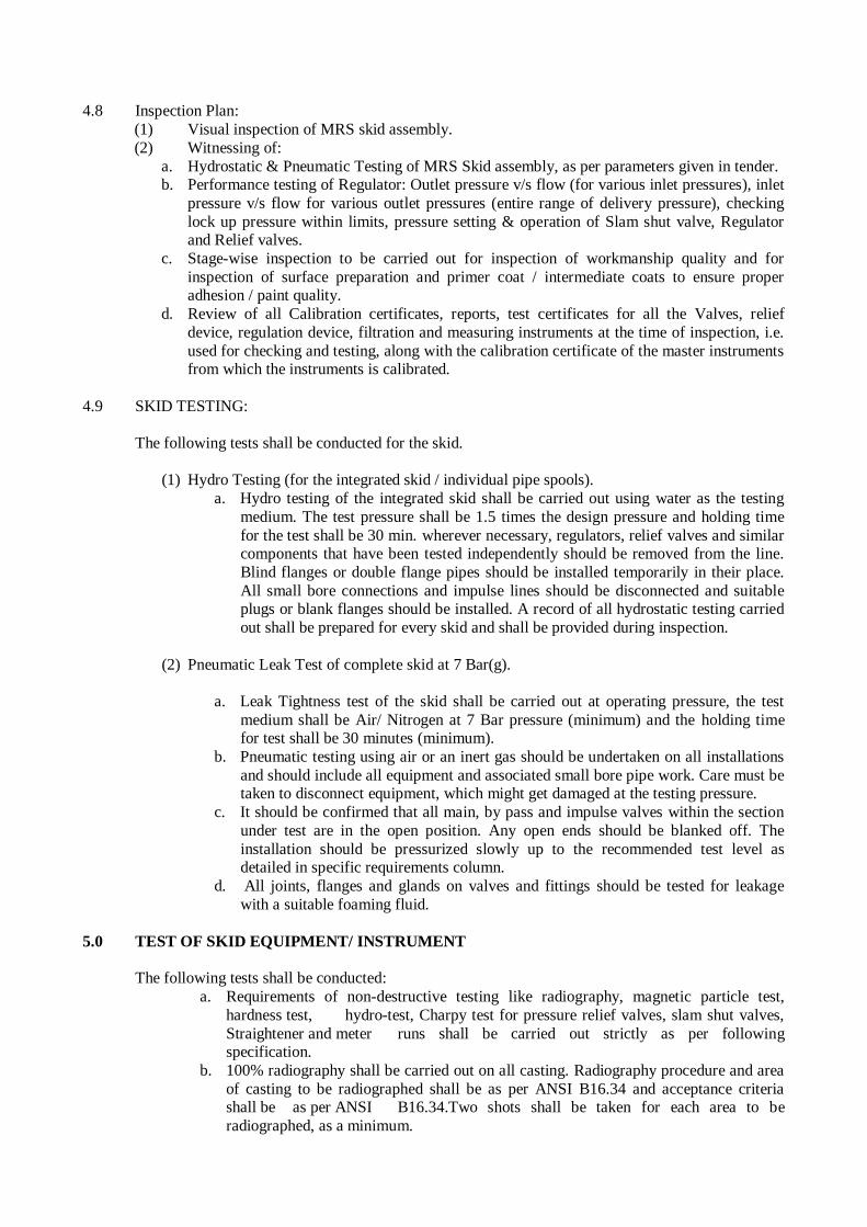
4.8 Inspection Plan:
(1) Visual inspection of MRS skid assembly.
(2) Witnessing of:
a. Hydrostatic & Pneumatic Testing of MRS Skid assembly, as per parameters given in tender. b. Performance testing of Regulator: Outlet pressure v/s flow (for various inlet pressures), inlet
pressure v/s flow for various outlet pressures (entire range of delivery pressure), checking
lock up pressure within limits, pressure setting & operation of Slam shut valve, Regulator and Relief valves.
c. Stage-wise inspection to be carried out for inspection of workmanship quality and for
inspection of surface preparation and primer coat / intermediate coats to ensure proper adhesion / paint quality.
d. Review of all Calibration certificates, reports, test certificates for all the Valves, relief
device, regulation device, filtration and measuring instruments at the time of inspection, i.e.
used for checking and testing, along with the calibration certificate of the master instruments from which the instruments is calibrated.
4.9 SKID TESTING:
The following tests shall be conducted for the skid.
(1) Hydro Testing (for the integrated skid / individual pipe spools).
a. Hydro testing of the integrated skid shall be carried out using water as the testing
medium. The test pressure shall be 1.5 times the design pressure and holding time
for the test shall be 30 min. wherever necessary, regulators, relief valves and similar components that have been tested independently should be removed from the line.
Blind flanges or double flange pipes should be installed temporarily in their place.
All small bore connections and impulse lines should be disconnected and suitable plugs or blank flanges should be installed. A record of all hydrostatic testing carried
out shall be prepared for every skid and shall be provided during inspection.
(2) Pneumatic Leak Test of complete skid at 7 Bar(g).
a. Leak Tightness test of the skid shall be carried out at operating pressure, the test
medium shall be Air/ Nitrogen at 7 Bar pressure (minimum) and the holding time for test shall be 30 minutes (minimum).
b. Pneumatic testing using air or an inert gas should be undertaken on all installations
and should include all equipment and associated small bore pipe work. Care must be taken to disconnect equipment, which might get damaged at the testing pressure.
c. It should be confirmed that all main, by pass and impulse valves within the section
under test are in the open position. Any open ends should be blanked off. The
installation should be pressurized slowly up to the recommended test level as detailed in specific requirements column.
d. All joints, flanges and glands on valves and fittings should be tested for leakage
with a suitable foaming fluid.
5.0 TEST OF SKID EQUIPMENT/ INSTRUMENT
The following tests shall be conducted:
a. Requirements of non-destructive testing like radiography, magnetic particle test,
hardness test, hydro-test, Charpy test for pressure relief valves, slam shut valves,
Straightener and meter runs shall be carried out strictly as per following specification.
b. 100% radiography shall be carried out on all casting. Radiography procedure and area
of casting to be radiographed shall be as per ANSI B16.34 and acceptance criteria shall be as per ANSI B16.34.Two shots shall be taken for each area to be
radiographed, as a minimum.
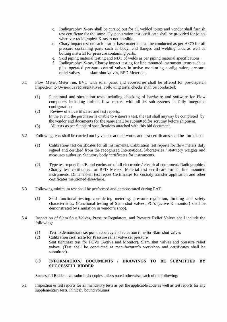
c. Radiography/ X-ray shall be carried out for all welded joints and vendor shall furnish
test certificate for the same. Dyepenetration test certificate shall be provided for joints
wherever radiography/ X-ray is not possible.
d. Chary impact test on each heat of base material shall be conducted as per A370 for all pressure containing parts such as body, end flanges and welding ends as well as
bolting material for pressure containing parts.
e. Skid piping material testing and NDT of welds as per piping material specifications. f. Radiography/ X-ray, Charpy impact testing for line mounted instrument items such as
pilot operated pressure control valves in active monitoring configuration, pressure
relief valves, slam shut valves, RPD Meter etc.
5.1 Flow Meter, Meter run, EVC with solar panel and accessories shall be offered for pre-dispatch
inspection to Owner/it's representatives. Following tests, checks shall be conducted:
(1) Functional and simulation tests including checking of hardware and software for Flow
computers including turbine flow meters with all its sub-systems in fully integrated
configuration. (2) Review of all certificates and test reports.
In the event, the purchaser is unable to witness a test, the test shall anyway be completed by
the vendor and documents for the same shall be submitted for scrutiny before shipment. (3) All tests as per Standard specifications attached with this bid document.
5.2 Following tests shall be carried out by vendor at their works and test certificates shall be furnished:
(1) Calibration/ test certificates for all instruments. Calibration test reports for flow meters duly
signed and certified from the recognized International laboratories / statutory weights and
measures authority. Statutory body certificates for instruments.
(2) Type test report for JB and enclosure of all electronics/ electrical equipment. Radiographic /
Charpy test certificates for RPD Meters. Material test certificate for all line mounted
instruments. Dimensional test report Certificates for custody transfer application and other certificates mentioned elsewhere.
5.3 Following minimum test shall be performed and demonstrated during FAT.
(1) Skid functional testing considering metering, pressure regulation, limiting and safety
characteristics. (Functional testing of Slam shut valves, PC’s (active & monitor) shall be demonstrated by simulation in vendor’s shop).
5.4 Inspection of Slam Shut Valves, Pressure Regulators, and Pressure Relief Valves shall include the
following:
(1) Test to demonstrate set point accuracy and actuation time for Slam shut valves
(2) Calibration certificate for Pressure relief valve set pressure Seat tightness test for PCVs (Active and Monitor), Slam shut valves and pressure relief
valves. (Test shall be conducted at manufacturer’s workshop and certificates shall be
submitted).
6.0 INFORMATION/ DOCUMENTS / DRAWINGS TO BE SUBMITTED BY
SUCCESSFUL BIDDER
Successful Bidder shall submit six copies unless noted otherwise, each of the following:
6.1 Inspection & test reports for all mandatory tests as per the applicable code as well as test reports for any
supplementary tests, in nicely bound volumes.
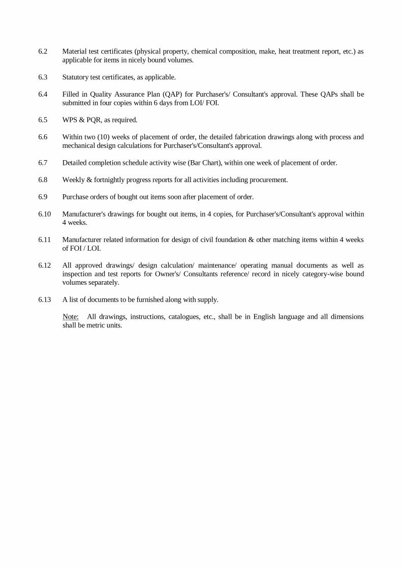
6.2 Material test certificates (physical property, chemical composition, make, heat treatment report, etc.) as
applicable for items in nicely bound volumes.
6.3 Statutory test certificates, as applicable.
6.4 Filled in Quality Assurance Plan (QAP) for Purchaser's/ Consultant's approval. These QAPs shall be
submitted in four copies within 6 days from LOI/ FOI.
6.5 WPS & PQR, as required.
6.6 Within two (10) weeks of placement of order, the detailed fabrication drawings along with process and
mechanical design calculations for Purchaser's/Consultant's approval.
6.7 Detailed completion schedule activity wise (Bar Chart), within one week of placement of order.
6.8 Weekly & fortnightly progress reports for all activities including procurement.
6.9 Purchase orders of bought out items soon after placement of order.
6.10 Manufacturer's drawings for bought out items, in 4 copies, for Purchaser's/Consultant's approval within 4 weeks.
6.11 Manufacturer related information for design of civil foundation & other matching items within 4 weeks
of FOI / LOI.
6.12 All approved drawings/ design calculation/ maintenance/ operating manual documents as well as
inspection and test reports for Owner's/ Consultants reference/ record in nicely category-wise bound volumes separately.
6.13 A list of documents to be furnished along with supply.
Note: All drawings, instructions, catalogues, etc., shall be in English language and all dimensions
shall be metric units.
DESIGN BASIS
1.0 INTRODUCTION
2.0 CODES & STANDARDS
3.0 ORDER OF PRECEDENCE
4.0 GAS COMPOSITION
5.0 DESIGN CRITERIA
6.0 ENVIRONMENTAL SPECIFICATIONS
7.0 EARTHING
8.0 GUIDELINES-PREPARATION OF DRAW
9.0 ERECTION, TESTING AND COMMISSIONING AT SITE
10.0 SPARES AND CONSUMABLES
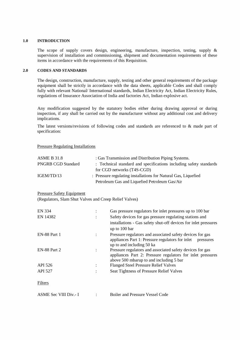
1.0 INTRODUCTION
The scope of supply covers design, engineering, manufacture, inspection, testing, supply & supervision of installation and commissioning, shipment and documentation requirements of these
items in accordance with the requirements of this Requisition.
2.0 CODES AND STANDARDS
The design, construction, manufacture, supply, testing and other general requirements of the package
equipment shall be strictly in accordance with the data sheets, applicable Codes and shall comply
fully with relevant National/ International standards, Indian Electricity Act, Indian Electricity Rules, regulations of Insurance Association of India and factories Act, Indian explosive act.
Any modification suggested by the statutory bodies either during drawing approval or during inspection, if any shall be carried out by the manufacturer without any additional cost and delivery
implications.
The latest versions/revisions of following codes and standards are referenced to & made part of
specification:
Pressure Regulating Installations
ASME B 31.8 : Gas Transmission and Distribution Piping Systems.
PNGRB CGD Standard : Technical standard and specifications including safety standards
for CGD networks (T4S-CGD)
IGEM/TD/13 : Pressure regulating installations for Natural Gas, Liquefied
Petroleum Gas and Liquefied Petroleum Gas/Air
Pressure Safety Equipment
(Regulators, Slam Shut Valves and Creep Relief Valves)
EN 334 : Gas pressure regulators for inlet pressures up to 100 bar
EN 14382 : Safety devices for gas pressure regulating stations and
installations - Gas safety shut-off devices for inlet pressures
up to 100 bar
EN-88 Part 1 : Pressure regulators and associated safety devices for gas
appliances Part 1: Pressure regulators for inlet pressures
up to and including 50 ka EN-88 Part 2 : Pressure regulators and associated safety devices for gas
appliances Part 2: Pressure regulators for inlet pressures
above 500 mbarup to and including 5 bar API 526 : Flanged Steel Pressure Relief Valves
API 527 : Seat Tightness of Pressure Relief Valves
Filters
ASME Sec VIII Div.- I : Boiler and Pressure Vessel Code
Metering Equipment
AGA Report No. 3 : Orifice Metering of Natural Gas and Other related Hydrocarbon
fluids
AGA Report No. 5 : Fuel Gas Energy Metering
AGA Report No. 8 : Compressibility factors of natural gas and other related
hydrocarbon gases
Pressure Measuring Equipment
BS EN 837-1 : Pressure gauges - Part 1: Bourdon tube pressure gauges;
dimensions, metrology, requirements and testing
BS EN 837-2 : Pressure Gauges - Part 2: Selection and Installation
Recommendations for Pressure Gauges
BS EN 837-3 : Pressure gauges - Part 3: Diaphragm and capsule pressure
gauges; dimensions, metrology, requirements and testing
3.0 ORDER OF PRECEDENCE
In the event of any conflict between specifications, related standards and codes, any other document,
the following order of priority shall govern and more stringent conditions shall be applicable:
a) PNGRB Regulation
b) Statutory Requirements
c) Design Basis
d) Data Sheet/QAP
e) P&ID
f) Drawings
g) Technical specification of particular item
h) Code and Standard
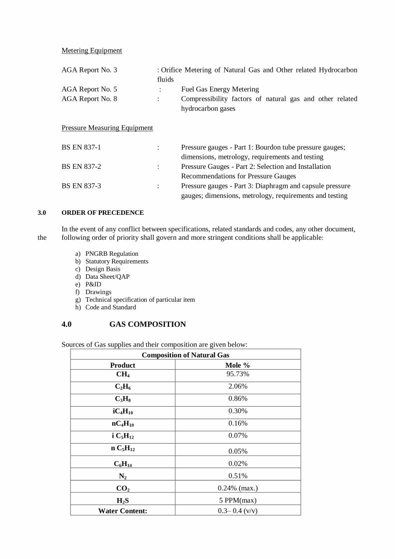
4.0 GAS COMPOSITION
Sources of Gas supplies and their composition are given below:
Composition of Natural Gas
Product Mole %
CH4 95.73%
C2H6 2.06%
C3H8 0.86%
iC4H10 0.30%
nC4H10 0.16%
i C5H12 0.07%
n C5H12 0.05%
C6H14 0.02%
N2 0.51%
CO2 0.24% (max.)
H2S 5 PPM(max)
Water Content: 0.3– 0.4 (v/v)
5.0 DESIGN CRITERIA
A) Pressure regulating skid should be typically consists of following main equipments:
Dry Gas filter
Pressure reduction skid
Metering/Pipingset up as per the P&ID
Inlet and outlet isolation valves.
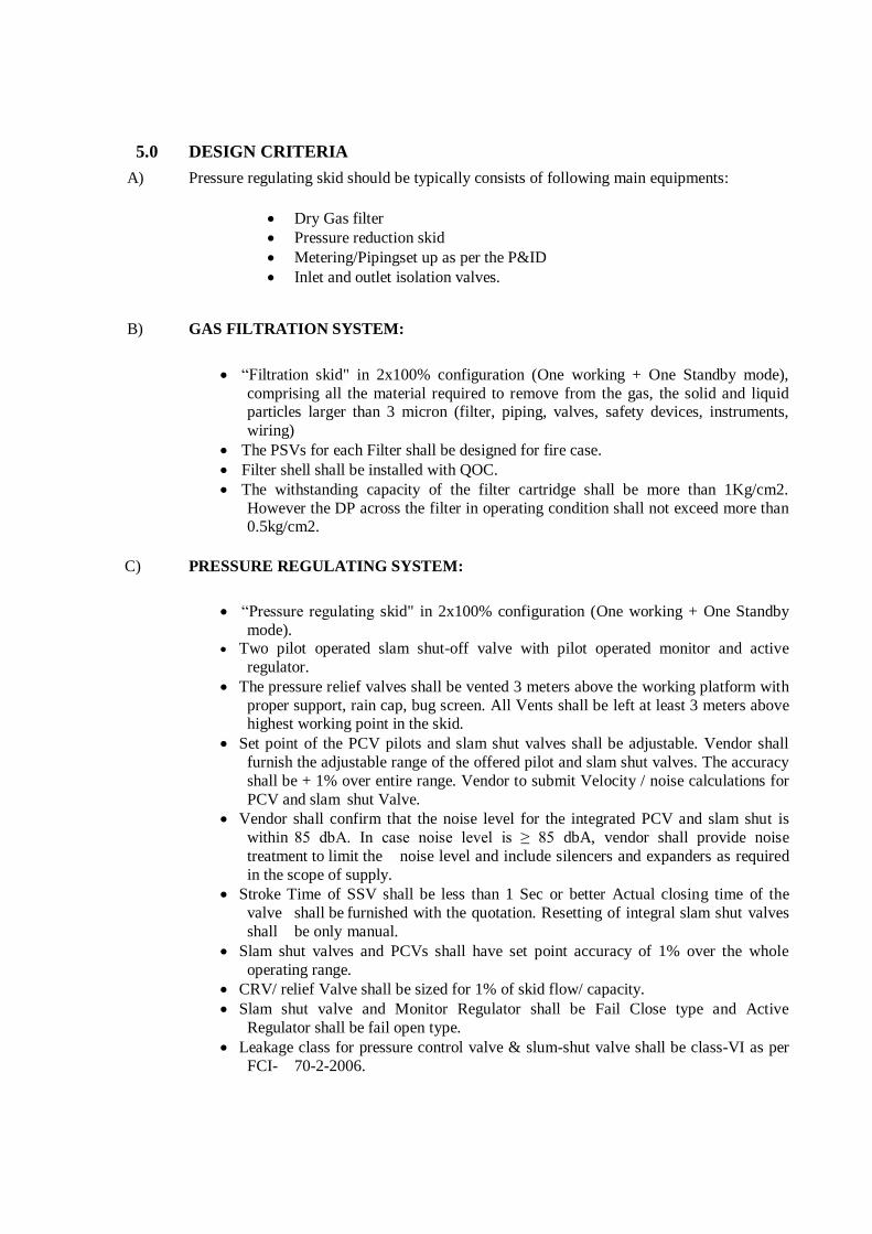
B) GAS FILTRATION SYSTEM:
“Filtration skid" in 2x100% configuration (One working + One Standby mode),
comprising all the material required to remove from the gas, the solid and liquid particles larger than 3 micron (filter, piping, valves, safety devices, instruments,
wiring)
The PSVs for each Filter shall be designed for fire case.
Filter shell shall be installed with QOC.
The withstanding capacity of the filter cartridge shall be more than 1Kg/cm2.
However the DP across the filter in operating condition shall not exceed more than 0.5kg/cm2.
C) PRESSURE REGULATING SYSTEM:
“Pressure regulating skid" in 2x100% configuration (One working + One Standby
mode). Two pilot operated slam shut-off valve with pilot operated monitor and active
regulator.
The pressure relief valves shall be vented 3 meters above the working platform with
proper support, rain cap, bug screen. All Vents shall be left at least 3 meters above highest working point in the skid.
Set point of the PCV pilots and slam shut valves shall be adjustable. Vendor shall
furnish the adjustable range of the offered pilot and slam shut valves. The accuracy
shall be + 1% over entire range. Vendor to submit Velocity / noise calculations for
PCV and slam shut Valve.
Vendor shall confirm that the noise level for the integrated PCV and slam shut is
within 85 dbA. In case noise level is ≥ 85 dbA, vendor shall provide noise
treatment to limit the noise level and include silencers and expanders as required
in the scope of supply.
Stroke Time of SSV shall be less than 1 Sec or better Actual closing time of the
valve shall be furnished with the quotation. Resetting of integral slam shut valves
shall be only manual.
Slam shut valves and PCVs shall have set point accuracy of 1% over the whole
operating range.
CRV/ relief Valve shall be sized for 1% of skid flow/ capacity.
Slam shut valve and Monitor Regulator shall be Fail Close type and Active
Regulator shall be fail open type.
Leakage class for pressure control valve & slum-shut valve shall be class-VI as per
FCI- 70-2-2006.
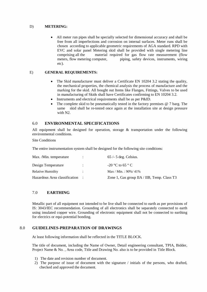
D) METERING:
All meter run pipes shall be specially selected for dimensional accuracy and shall be
free from all imperfections and corrosion on internal surfaces. Meter runs shall be chosen according to applicable geometric requirements of AGA standard. RPD with
EVC and solar panel Metering skid shall be provided with single metering line
comprising all the material required for gas flow rate measurement (flow meters, flow metering computer, piping, safety devices, instruments, wiring
etc).
E) GENERAL REQUIREMENTS:
The Skid manufacturer must deliver a Certificate EN 10204 3.2 stating the quality,
the mechanical properties, the chemical analysis the process of manufacture and the
marking for the skid. All bought out Items like Flanges, Fittings, Valves to be used in manufacturing of Skids shall have Certificates confirming to EN 10204 3.2.
Instruments and electrical requirements shall be as per P&ID.
The complete skid to be pneumatically tested in the factory premises @ 7 barg. The
same skid shall be re-tested once again at the installation site at design pressure
with N2.
6.0 ENVIRONMENTAL SPECIFICATIONS
All equipment shall be designed for operation, storage & transportation under the following environmental conditions.
Site Conditions
The entire instrumentation system shall be designed for the following site conditions:
Max. /Min. temperature : 65 /- 5 deg. Celsius.
Design Temperature : -20 °C to 65 ° C
Relative Humidity : Max / Min. : 90%/ 41%
Hazardous Area classification : Zone 1, Gas group IIA / IIB, Temp. Class T3
7.0 EARTHING
Metallic part of all equipment not intended to be live shall be connected to earth as per provisions of
IS: 3043/IEC recommendation. Grounding of all electronics shall be separately connected to earth
using insulated copper wire. Grounding of electronic equipment shall not be connected to earthing for electrics or equi-potential bonding.
8.0 GUIDELINES-PREPARATION OF DRAWINGS
At least following information shall be reflected in the TITLE BLOCK.
The title of document, including the Name of Owner, Detail engineering consultant, TPIA, Bidder, Project Name & No. , Area code, Title and Drawing No. also is to be provided in Title Block.
1) The date and revision number of document. 2) The purpose of issue of document with the signature / initials of the persons, who drafted,
checked and approved the document.
Revisions shall be clearly identified on all documents / drawings and modified portions shall be
clouded
in case of drawings and outlined ( shown with Revision) in case of documents.
All documents shall be listed. From the list it should be possible to keep track of various issues and
revisions of the documents. The list shall be regularly updated to reflect the latest revisions based on
project requirements.
9.0 ERECTION, TESTING AND COMMISSIONING AT SITE
Bidder shall be responsible for erection, commissioning; performance test of system, FAT, all
required testing, SAT and field trial run of MRS. 10.0 SPARES AND CONSUMABLES
Bidder shall provide for spare parts and consumables required during the erection, commissioning,
testing, defect liability period and trail run.
1.0 GENERAL
1.1 This specification together with all annexure enclosed, covers the requirements for the design, engineering, manufacturing, testing, inspection and supply of MRS units along with all the
accessories.
1.2 In the event of any conflict between this specification, datasheets, related standards codes etc., the
more stringent shall apply.
1.3 Owner’s/Consultant datasheet for Cartridge filters, Pressure regulators with Slam shut valve, RPD
flow meters, EVC, Pressure relief valves, Pressure/Differential pressure gauges and accessories
indicating materials for body, internals etc. has been attached. However, this does not absolve the
bidder’s responsibility for proper selection with respect to the fluid & its operating/design conditions. Proper sizing & selection of Cartridge filters, flow meter, Pressure Regulators, Slam shut
valves, Pressure relief valves, Pressure instruments, Temp. Instruments etc. and accessories. Sizing
Calculation required for Cartridge filter, PCV’s, SSVs, PSV etc and Noise calculation required for PCVs are bidder’s responsibility.
Process parameters for skids are given in P&ID. Bidder shall take single point responsibility for the
design & performance of the skids based on the data sheet and specification furnished and taking
into consideration successful operation, safety as per the established international standards for complete skids. As a part of the skid, design & engineering of following shall be included by bidder:
• Make model and detail specification of each item. • Fixing pressure drop across various elements
• Sizing & Selection of cartridge filters, PCVs, Slam shuts, EVC and PSV etc.
• Noise calculations for PCVs and Slam shuts valves. • Selection of ranges for Pressure transmitter, Temp. Transmitter, Pressure Gauges, Differential
Pressure Gauges, Temperature Gauges, RTDs etc.
• All design performance characteristics.
• Individual dimensions of each item. • Overall dimension of each unit.
• Weight of each unit.
1 .4 Bidder shall consider all the requirements of this specification along with those as per relevant
standards and shall assume total responsibility including all aspects of engineering, design,
certification etc. for filtration, pressure reducing and metering units.
1.5 Bidder to note that all the items including cartridge filters, pressure regulators and slam shut valves,
RPD meters, pressure safety valves, flow computer etc. shall be procured from reputed vendors only.
1 .6 Bidder’s quotations shall include the detailed specifications for all the items of filtration, let down &
metering units. The bidder shall also offer any instruments /equipments required for safe and
efficient operation of the system.
1.7 Bidder to furnish
a) The maximum flow rate (in Sm3/hr) at minimum inlet pressure for all PCVs at valve full open condition.
b) Min. flow rate (in Sm3/hr) through each PCV without damaging the trim and valve internals
at min. inlet pressure. c) Flow rate vs. trim lift curve to justify the valve range ability and valve regulation
characteristics.
1.8 All units of measurements in bidder’s specification sheets shall be same as those in owner’s data
sheets.
1.9 All material specification for the various parts in the bidder’s specifications sheets shall be to the same standard as those in owner data sheets.
1.10 Bidder shall enclose catalogues giving detailed technical specification and other information for cartridge filters, self actuated pressure control valve, slam shut valves, pressure relief valves,
pressure/ temperature gauges, RPD flow meters, EVC, Pressure transmitter, Temp transmitter etc.
covered in the bid.
1.11 Bidder’s quotation, catalogues, drawings, operating and maintenance manuals etc. shall be only in
English language.
1.12 Bidder shall submit subsequent to award of contract the sizing details & specification of all the
instruments and piping items make and model, skid details etc. The relevant catalogue, technical
literature shall also be furnished.
1.13 All drains/vents should be having provision for putting end cap and shall be complete with wire seal.
2.0 GENERALITIES
2.1. Definition
Subject to the requirements of the context, the terms used in this specification are given the following meaning:
OWNER GODAVARI GAS PVT. LTD
BIDDER Designates the individual or legal entity with whom the order has
been concluded by the OWNER. The term “BIDDER” may be used
indifferently or a supplier, a manufacturer, an erection contractor, etc.
GOODS and/or SERVICES Designate, depending on the case, all or part of the drawings or
documents, substances, materials, material, equipment, structures, plant, tools, machinery etc., to be studied, designed, manufactured,
supplied, erected, built, assembled, adapted, arranged or put into
service by the CONTRACTOR under the AGREEMENT, including all the studies, tasks, works and services specified by the order. The
Terms GOODS or SERVICES may by indifferently used one for
the other as required by the context.
PROJECT Designates the aggregate of GOODS and/or SERVICES to be
provided by one or more CONTRACTORS.
SHALL This verbal form indicates requirements strictly to be followed in order to confirm to the standards and from which no deviation is
permitted.
SHOULD This verbal form indicates that among several possibilities one is particularly suitable without mentioning or excluding others or that
a certain course of action is preferred but not necessarily required.
MAY This verbal form indicates a course of action permissible within the limits of this standard.
CAN This verbal form used for statements of possibility & capability, whether material, physical or casual.
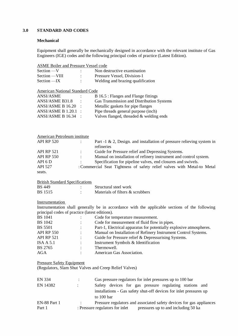
3.0 STANDARD AND CODES
Mechanical
Equipment shall generally be mechanically designed in accordance with the relevant institute of Gas
Engineers (IGE) codes and the following principal codes of practice (Latest Edition).
ASME Boiler and Pressure Vessel code
Section —V : Non destructive examination
Section —VIII : Pressure Vessel, Division-1 Section —IX : Welding and brazing qualification
American National Standard Code
ANSI/ASME : B 16.5 : Flanges and Flange fittings ANSI/ASME B31.8 : Gas Transmission and Distribution Systems
ANSI/ASME B 16.20 : Metallic gaskets for pipe flanges
ANSI/ASME B 1.20.1 : Pipe threads general purpose (inch) ANSI/ASME B 16.34 : Valves flanged, threaded & welding ends
American Petroleum institute
API RP 520 : Part -1 & 2, Design. and installation of pressure relieving system in
refineries API RP 521 : Guide for Pressure relief and Depressing Systems.
API RP 550 : Manual on installation of refinery instrument and control system.
API 6 D : Specification for pipeline valves, end closures and swivels. API 527 : Commercial Seat Tightness of safety relief valves with Metal-to Metal
seats.
British Standard Specifications BS 449 : Structural steel work
BS 1515 : Materials of filters & scrubbers
Instrumentation
Instrumentation shall generally be in accordance with the applicable sections of the following
principal codes of practice (latest editions). BS 1041 : Code for temperature measurement.
BS 1042 : Code for measurement of fluid flow in pipes.
BS 5501 : Part-1, Electrical apparatus for potentially explosive atmospheres.
API RP 550 : Manual on Installation of Refinery Instrument Control Systems. API RP 521 : Guide for Pressure relief & Depressurising Systems.
ISA A 5.1 : Instrument Symbols & Identification
BS 2765 : Thermowell. AGA : American Gas Association.
Pressure Safety Equipment (Regulators, Slam Shut Valves and Creep Relief Valves)
EN 334 : Gas pressure regulators for inlet pressures up to 100 bar
EN 14382 : Safety devices for gas pressure regulating stations and
installations - Gas safety shut-off devices for inlet pressures up
to 100 bar
EN-88 Part 1 : Pressure regulators and associated safety devices for gas appliances
Part 1 : Pressure regulators for inlet pressures up to and including 50 ka
EN-88 Part 2 : Pressure regulators and associated safety devices for gas appliances
Part 2 : Pressure regulators for inlet pressures above 500 mbar up to and including 5 bar
API 526 : Flanged Steel Pressure Relief Valves
API 527 : Seat Tightness of Pressure Relief Valves
IGEM/TD/13 : Pressure regulating installations for Natural Gas, Liquefied
Petroleum Gas and Liquefied Petroleum Gas/Air
DIN-43760 : Temperature vs Resistance curves for RTDs.
DIN-19234 : Electrical Distance Sensors; DC interface for Distance Sensor and
Signal Convertor.
4.0 SCOPE OF WORK
4.1 Bidder’s scope shall include complete design, engineering, manufacturing, integration, performance
testing, inspection, FAT, supply, supervision of erection, testing & commissioning, &
documentation of MRS skids as per the respective P&IDs, data sheets and other specifications
enclosed herewith.
4.2 DRS units shall be comprised of the following items as per enclosed P & IDs, the followings:
Skids shall consist of following generally:-
i) Cartridge filters with differential pressure gauges, Safety Relief Valves, along with all
accessories (as indicated in P & ID).
ii) Self actuated pressure control valve(s) with integral slam shut or individual monitor and SSV
as indicated in respective P & ID’s.
iii) Upstream straight lengths, profiler, downstream straight lengths & downstream straight lengths
shall be suitable for RPD flow meters and as per applicable standard/code.
iv) Pressure regulator shall be designed in such a way that inlet pressure does not come in direct
contact with the main valve diaphragm (i.e. loading type of regulator only shall be accepted).
v) Regulator shall be designed as per EN 334 and SSV shall be as per EN 14382.
vi) Safety Relief Valves
vii) Pressure gauges, temperature gauges, Pressure transmitter, RTDs
viii) Complete piping, fittings, valves, flanges, expanders, reducers; vent arrangements etc. as
required as per P & IDs to make the skids complete in all respects and ready for installation.
ix) Piping, tubing, fittings, valves etc. as required for the installation of Instruments.
x) Cabling from various analog, digital inputs (all instruments) up to EVC enclosure mounted on
skids.
xi) Steel structures for skid & supports, platform & maintenance access as required.
xii) Special installation tools as required for normal operation and maintenance.
xiii) For pressure transmitter 1/2” tapping along with 1/2” SW isolation valve shall be provided
along with SS 316 manifold.
xiv) Two ½” tapping on the filter differential pressure gauge along with isolation valves, impulse
tubing and manifold etc.
xv) For temperature element, bidder shall provide SS 316 flanged thermo well. The connection on the thermo well for temperature element shall be (1/2”) NPT (F).
xvi) Manual isolation valves
xvii) Solar Panel with battery back-up for EVC.
xviii) Any other item required to complete the skid in all respects as per technical specs and
mentioned in tender document.
xix) Cabinet / Enclosure for entire skid shall be as per cabinet specification attached elsewhere in tender document.
4.3. The skids shall be complete in all respects, ready for installation and commissioning at the respective locations. There shall be minimum work to be done at site. All field mounted instruments shall be
supplied loose to avoid damages of same during transportation of the skids. However, PCVs with
integral slam shut, RPD flow meter, flow straightner, Monitor valve shall be duly mounted on the skids. The EVC shall be fully configured and all the necessary data as per data sheet should be
configured in EVC to minimize site work. The details regarding installation of MRS, shall be clearly
described in the “Installation Manual” especially made for skid installation and the same shall be
submitted while dispatching skids.
4.4 End connections for the skids shall be flanged and shall be supplied with companion flanges.
4.5 All items in the skid shall be properly supported to avoid vibration. Special supports, as required,
shall also be supplied by bidder.
4.6 All piping materials shall be as per piping material specification/codes specified. The piping fabrication work shall confirm to the requirements of ANSI B31.8.
4.7 The skid shall be sized considering ease of transportation. Skid may be brazen up with flanged end to end connections for connection at site. Bidder to supply complete skid including interconnecting
piping between filtration, let down (PRS) and metering skid.
4.8 All instruments on the skid shall be easily accessible.
4.9 All the instrument enclosures mounted in the field shall be weather proof / ex-proof conforming to
IP-65/ NEMA -4/ NEMA -7 as a minimum.
4.10 Completeness of the skid including matching the end connections, size and rating, providing
appropriate piping length, necessary expanders/ reducers as per piping specification given herein shall be ensured.
4.11 Bidder shall furnish Bill of Materials for the skid, and completeness of the Bill of Materials for the skid to meet the functional requirement of specifications of tender document is bidder’s
responsibility.
4.12 The packaged assemblies shall include all interconnecting piping, valves, inlet and outlet manifolds, control equipment and components, regulators, meters and all other necessary components required
to deliver a complete operational system for each location. Skid mounted terminals shall be installed
at the locations nominated in this documentation and in accordance with local government rules and regulations applying to such facilities. The bidder shall be responsible for determining all applicable
requirements and ensuring compliance.
4.13 Bidder shall submit all drawings and documents as per vendor data requirement of Owner.
4.14 Commissioning spares as required shall be included as part of the offer. A list shall be attached along with the bid. These shall be supplied along with skids.
4.15 Bidder shall quote separately for two years operation and maintenance spares for the skids as per the SOR.
4.16 The pressure relief valves as indicated shall be vented 3 meters above the working platform with proper support, rain cap, bug screen. All Vents shall be left at least 3 meters above highest working
point in the skid.
4.17 Bidder shall furnish sizing calculation details for all the pressure relief valves, regulator from valve manufacturer for Owner / Consultant’s review for approval during detailed engineering.
4.18 Set point of the PCV pilots and slam shut valves shall be adjustable. Bidder shall furnish the adjustable range of the offered pilot and slam shut valves. Bidder to submit Velocity / noise
calculations for Integral assembly of PCV and slam shut Valve.
4.19 Pressure regulators shall be fail open/close type as indicated in the data sheets. Bidder shall confirm
that the noise level for the integrated PCV and slam shut is within 85 dbA. In case noise level is ≥ 85
dbA, bidder shall provide noise treatment to limit the noise level and include silencers and expanders
as required in the scope of supply.
4.20 Any soft material used in valves shall be able to retain its functional properties for minimum period
of 3 years.
4.21 Closing time of slam shut valve shall be less than 1seconds or better for all sizes of the valves.
Actual closing time of the valve shall be furnished with the quotation.
4.22 Resetting of integral slam shut / PCV valves shall be only manual.
4.23 Slam shut valves and PCVs shall have set point accuracy of 1% over the whole operating range.
4.24 The allowable tolerance in the set pressure for the pressure relief valves shall be as per relevant
codes. Spring material of pressure relief valve shall be based on releving temperature.
4.25 The relief valve shall meet the seat tightness requirement as per API 527.
4.26 All materials to be used in construction of valves shall be suitable for Natural Gas services.
4.27 Bidder shall be responsible for the design of filters for the successful operation of the meters on the
skids. Filter shall be cartridge type shall be provided with a differential pressure Gauge.
4.28 For Integral slam shut valve sizing, a maximum velocity of 40 m/s will be considered.
4.29 All the accessories of the valve shall be weather proof as per NEMA 4 / IP 65.
4.30 All the calculations and units of measurement shall be metric standards only.
4.31 Skid instruments mounted on the channel shall be suitable for installation in tropical hot and humid
climate.
Temp range: -5 - 65 deg. C
Relative Humidity: 100 %
4.32 Flow direction shall be clearly marked on the meter body.
4.33 Flow profiler shall be provided at the RPD meter inlet to eliminate swirls and cross current setup by the pipe fittings, valves or regulators preceding the meter inlet piping where specified. Flow Profiler
shall be a bundle of SS 316 tubes as per AGA. Bidder shall furnish complete details/design of
straight length (upstream/downstream).
4.34 End connection details shall be as per data sheets.
4.35
a) Bidder shall take single point responsibility for the design, fabrication, assembly, testing and
performance of the metering skids.
b) The fabrication, assembly, testing and inspection works have to be carried out at Bidder’s works
or works designated by the Bidder. In case of Bidder designated works, the facility should have
established proven track.
4.36 Technical Requirements for Skid Mounted Terminals:
1) Bidder shall be responsible for the complete supply and fabrication of skids including
foundation bolts.
2) The piping items shall conform to specification and data sheets included in the Engineering documents.
3) The skid shall be supplied in segments of length and weight, suitable for easy transportation. handling at site during installation. If the skid(s) are supplied in more than one segment,
necessary flange, nuts, bolts and gaskets for installation and bidder shall also supply assembly
at site.
4) Piping material (pipes, fittings, flanges, etc.) for high point vents shall be supplied loose by
bidder to be installed and assembled at site.
5) Bidder shall submit general arrangement drawings for skid indicating the elevations of inlet
and outlet flanges, overall skid dimensions and the weights of the individual segments.
6) Bidder shall furnish details of skid foundation.
7) Bidder shall submit complete dimensioned drawings for skid indicating materials of all piping
components for company’s approval prior to procurement and commencement of fabrication of skid.
4.37 The sizes of pipes, meter and valves given in P&ID shall be minimum and bidder has to size and submit calculation for the same, and if required higher size meter to be given by Bidder.
4.38 Bidder shall be fully responsible for proper integration of their supplied systems with Owner’s SCADA (RTU) systems and shall provide all the technical details to Owner for configuration at
SCADA and GSM modem end. Configuration in the supplied control panel shall be bidder’s
responsibility.
4.39 MRS shall be designed considering process parameters i.e. Flow rate, Inlet & outlet (delivery)
Pressure given in P&ID. Minimum size & rating of skid / components selected & offered shall be as
indicated in P&ID. Offered size shall be same or higher that the sizes indicated in P&ID after sizing calculation.
4.40 All the instruments shall be provided with canopies of adequate size to protect instruments from
direct rain & sunlight. All such canopies shall be prefabricated type.
4.41 The custody transfer equipments at field like transmitters (pressure & temperature) shall be installed in environmental enclosure to minimize the effects of ambient temperature variations and shall be
lockable for prevention of unauthorized data entry. The size of the cabinet shall be suitable for
removing and fixing of transmitters for ease of maintenance. The transmitters shall be fixed in mounting brackets inside the cabinet. The cabinet shall be mounted and fixed in the skid.
4.42 Tube fittings used for the installation of instruments shall be tested as per BS 4368 or equivalent standards.
4.43 All interconnecting instruments cables, earthing cables in skid and cables to control room shall be
armored. All signal and alarm cables shall be individual pair shielded and overall shielded. Bidder shall follow the cable specifications as per signal cable standard specification.
4.44 All field transmitters and other instruments shall be certified weatherproof to minimum IP65 and safe / ex-proof suitable for hazardous area classification IEC Zone 1, Gr.IIA/ IIB, T3.
4.45 All limit switches, junction boxes, cable glands & accessories shall be certified weather proof and ex-proof.
4.46 The certification for use of all instrumentation items including junction boxes / cable glands etc. in
hazardous areas shall be as follows:
Certificates from statutory authorities like BASEEFA, FM, CENELEC, ATEX etc.
for items of foreign origin and from CMRI etc. for items of Indian origin.
Approval certificate from CCOE (Chief Controller of Explosives) for all
instrumentation items which are ex-proof to be installed in India, irrespective of country of origin and the same is mandatory.
Approval certificate from BIS (Bureau of India Standards) for all flameproof
instruments manufactured in India.
4.49 All field mounted instrumentation items shall be suitable for continuous working in outdoor installations, considering temperature, humidity etc. as per data given elsewhere in this bid. Ingress
protection for all field instruments and enclosures / junction boxes / cable glands etc. shall be IP-65
as minimum. Instruments mounted on the skid shall be suitable for installation in tropical hot and humid climate considering temperature : -5 to 65˚ C ; Humidity : 100%.
4.50 The bidder shall include isolation valves in Impulse lines for the pressure regulators and monitors slam shut valves etc. The pressure instruments shall be provided with individual process isolation
valves and block and bleed manifolds.
4.51 Transmitters shall be microprocessor based “SMART” type. All transmitters shall be 2 wire, and
provided with integral output meter with digital display. The temperature transmitters shall be Pt 100 RTD sensor type (class A, 4 wire type) with integral head mounted SMART transmitter with two
wire 4-20 mA DC output, 24 VDC loop powered complete with local output meter (LCD type). The
temperature transmitter shall be provided with flanged thermowell of 316SS material fabricated from drilled bar stock.
4.52 Bidder shall furnish details of foundation required for DRS skid.
4.53 In view of the total weight and overall dimensions of the skids, bidder may decide to fabricate and
transport the skid in more than one part. In that case, bidder shall ensure that the site job shall only
be limited to bolting together these parts at site and no further welding or joining of components
together etc. are required. The responsibility of such jointing together and its proper functioning
would rest on the bidder.
4.54 The up-stream & downstream meter run for flow meter shall be cold insulated. This is to ensure even
heat transfer throughout the meter run for the environmental conditions given in the tender. The
thermo-wells & impulse tubing for the custody transfer transmitters to be cold insulated.
4.55 Flow Computer Validation Software: Bidder to provide licensed Software in the name of Owner or
authenticating the algorithm written in the Flow Computer as per AGA guidelines. Bidder to provide
the necessary hardware / software (licensed in favour of Owner) for configuration of Flow computer and other instruments (if any). Bidder to provide all the details / soft-wares for SCADA
communication / GSM Modem.
4.56 The Bidder shall assume single point responsibility for all aspects of the work. This shall include
Timely completion, liaison with VENDOR of specified items, co-ordination of the work, quality and
guarantee for the equipment.
5.0 CERTIFICATION FOR CUSTODY TRANSFER
5.1 The flow computer offered shall be certified by a suitable authority of the country of origin for use in custody transfer applications.
5.2 The bidder shall furnish the regulations of the certifying authority considered by him for custody transfer applications. If other instruments also need to be certified as per the regulations the same
shall be complied with.
6.0 TESTING AND INSPECTION
6.1 All materials and equipment shall be factory tested before shipment in the presence of owner’s
representative. No material shall be transported to site until all required tests have been carried out and equipment is certified as ready for shipment. Acceptance of equipment or the exemption of
inspection or tests thereof, shall in no way absolve bidder responsibility for delivering equipment
meeting the requirements of the specifications. Following tests shall be included.
1. Material test certificate, hydrostatic test certificate for self actuated pressure control valves, slam
shut valves, pressure relief valves, isolation valves and for all piping /valves of skid.
2. Testing to demonstrate set-point accuracy and actuation time for integral Slam shut valves.
3. Testing to demonstrate the set point accuracy for self actuated pressure control valves for the complete range of pressure and flow conditions.
4. Calibration certificate for pressure relief for set pressure and all field instruments.
5 Seat tightness test for self actuated integral slam shut valves, pressure relief valves
6. Test certificate for all field instruments such as PGs, TGs, DPGs, PTs & TTs.
7. Certificates from statutory body for limit switch being flame proof and weather proof.
8. Skid piping material testing and NDT of welds as per PMS.
9. The skid hydro testing.
10. Leak test of complete skid
11. Skid functional testing considering metering, pressure regulation, limiting and safety
characteristics.
6.2 Bidder shall perform the usual standard tests to maintain quality control procedures. Bidder shall submit these certificates for review of Owner before starting inspection. Bidder shall be responsible
for testing and complete integration of the system. Detailed procedures of test and inspection shall be
submitted by the bidder for review before order and mutually agreed upon.
Inspection will be done by Owner/Owner representative at bidder’s shop. For this inspection, labor,
consumable, equipment and utilities as required shall be in bidder’s scope.
6.3 Testing and inspection works have to be carried out at Bidder’s works or works designated by the
bidder.
6.4.1 The Bidder must submit a certificate EN 10204 3.2 stating the relevant quality of the Supplied
DRS.
7.0 DOCUMENTATION
The Owner’s vendor data requirement sheet indicates detailed drawings, data and catalogs required
from the bidder. The required number of reproducible and prints should be dispatched to the address
mentioned, adhering to the time limits attached.
Final drawings from the bidder shall include dimensional details, weight, mounting details and any
other special requirements etc. for the skids. All dimensions in general shall be in millimeters.
Bidder shall furnish all manuals necessary to test, operate and maintain the system.
8.0 NAME PLATE
Each skid and all the instruments in the skid shall have a SS nameplate attached firmly to it at a visible place furnishing the following information:
Tag number as per Owner’s data sheets.
Body sizes in inches and the valve Cv.
Set pressure range or flow range.
Flow range in Sm3/hr
Rating
Bidder’s Name & model number
9.0 PAINTING
9.1 All exposed carbon steel parts to be painted shall be thoroughly cleaned from inside and outside to remove scale, rust, dirt and other foreign materials by wire brushing and sand blasting as applicable.
Minimum acceptable standard in case of power tool cleaning shall be St. 3 and in case of blast
cleaning shall be Sa 2-1/2 as per Swedish Standard SIS 0055900.
9.2 Non-ferrous materials, austenitic stainless steels, plastic or plastic coated materials, insulated
surfaces of equipment and pre-painted items shall not be painted.
9.3 Stainless steel surfaces both inside and outside shall be pickled and passivated.
9.4 Machined and bearing surfaces shall be protected with varnish or thick coat of grease.
9.5 Depending on the environment, following primer and finish coats shall be applied.
Environment Description
1) Normal Industrial Surface Preparation : Sa 2-1/2
Primer : 2 coats of red oxide zinc chromate each 25
micron thick
Finish coat : 2 coats of synthetic enamel, each 25 micron
thick.
2) Corrosive Industrial Surface Preparation : Sa 2-1/2
Primer : 2 coats of epoxy zinc chromate each 35
micron thick
Finish coat : 2 coats of epoxy high build paint, each 100
micron thick.
3) Coastal & Marine Surface Preparation : Sa 2-1/2
Primer : 2 coats of high build chlorinated rubber zinc phosphate each 50 micron thick
Finish coat : 2 coats of chlorinated rubber paint, each 35
micron thick.
4) All Environment Surface Preparation : Sa 2-1/2 (80-4000 C)
Finish coat : 2 coats of heat resistant aluminium paint
suitable for specified temp, each 20 micron
thick. (All values refer to dry film thickness).
9.6 The valves in carbon steel body shall be painted light gray (RAL 7038). Skid piping hall be canary
yellow.
9.7 Bidder to ship supply of primer and the paint to permit on-site repair of shipping damage (if any) to
the factory coatings.
10.0 SHIPPING 10.1 All threaded and flanged opening shall be protected to prevent entry of foreign material.
10.2 All the field mounted instruments shall b supplied loose to avoid damages during transportation.
10.3 Skids shall bear proper shipping markings.
10.4 Shipping details like gross wt., net wt., volume, dispatch point, made of dispatch, mode of package etc. for each type of metering skid shall be provided with the offer.
11.0 REJECTION
Bidder shall make his offer in detail, with respect to every item of the Purchaser’s specification. Any
offer not conforming to this shall be summarily rejected.
12.0 INFORMATION TO BE SUPPLIED WITH TENDER
The bidder shall provide at the time of tendering a complete detailed engineering package in accordance with the vendor data requirement and shall include but not necessarily be limited to the
same.

13.0 WARRANTY& DEFECT LIABILITY PERIOD
The bidder shall amend repair or replace with new materials any defects or deficiencies in the plant and/or work which become apparent at any time or from time to time, within the period of twelve
(12) months occurring from the date of commissioning.
If the bidder does not make good those defects or deficiencies in the supplied MRS skid within a
reasonable time of having been given prior written notice by the Owner to do so, the Owner may
arrange for such defects or deficiencies to be remedied by others at the risk and expenses of the bidder, but without prejudice to any other rights which Owner has under the Contract in respect of
those defects or deficiencies.
FILTER SYSTEM
1.0 INTRODUCTION
The technical specification deals with the requirements for the design, procurement and erection of
the filtration system.
2.0 GENERALITIES
2.1 Codes, Standards & Legal Requirements
Following codes & standards (latest edition) shall be followed for design, manufacture, testing etc. of the equipment:
ASME Sec-VIII Div-1 : Boiler and Pressure Vessel Code
ASME Sec-IX : Welding and Brazing Qualifications
ASME Sec-II & ASTM : Material Specifications
ANSI B16.5 : Pipe Flanges & Pipe Fittings
ANSI B16.1 : Forged Steel Fittings Socket Welded & Threaded
ANSI B16.47 : Large Diameter Steel Flanges
ANSI B36.10 : Welding & Seamless Wrought Steel Pipe
In case of contradiction the more stringent requirement will govern.
2.2 Review & Approval
Whenever OWNER and/or OWNER’S REPRESENTATIVE review and/or approval is requested for
a document submitted by the Bidder or before an action is implemented by the Bidder. Such review
and/or approval shall always be requested in writing by the Bidder to the OWNER and/or
OWNER’S REPRESENTATIVE before any action is taken related to this review and/or approval. OWNER and/or OWNER’S REPRESENTATIVE approval shall always be given in writing.
3.0 DESCRIPTION
The system shall consist of two identical streams with two Isolation Valves each at Inlet and Outlet
of each stream.
3.1. Inlet Connection
One process inlet connection (Refer P & ID) with Manual Operated Isolation Valve.
Thermometer, manometer and pressure transmitter.
3.2. Outlet Connection
Two process outlet connection (Refer P & ID).
FOR EACH STREAM
3.3. Inlet Valve
• One manual IDB valve (Internal Double Block & Bleed)) as per P&ID.
3.4. Outlet Valve
• One manual DB valve (internal Double Block & Bleed).
3.5. Coalescing Filter for each stream
One Coalescing filter, made of carbon steel, designed according to the ASME VIII Div. 1 code, with the following requirements:
• The Coalescing filter is designed to remove the liquid and solid particles above 3 microns;
• An impact test @ 0°C is required for the material of the shell and the heads;
• All the materials are to be delivered with a 3.1 B certificate (DIN 50049);
• A relief valve is fit on the shell side;
• Shell and heads material thickness shall include a 1.5 mm corrosion allowance;
• Typically, the filter is provided with Manometer and Differential pressure Gauge, pressure safety valve, vent valves, manual valves in series, (one block valve and one throttling valve) and drain
valves manual valves in series, (one block valve and one throttling valve).
• Dished ends shall be of seamless construction, type 2:1 ellipsoidal type and shall be heat treated after forming as per ASME Sec. VIII Div.1.
• All nozzles less than or equal to 2" NB size shall be provided with 2 Nos. 6mm thick stiffeners at
90 degree to each other.
• All nozzles above 3" NB size, shall be provided with reinforcement pads. Calculations for
reinforcement pads as per ASME shall be submitted for purchaser's approval. Alternatively, Purchaser’s standard shall be followed.
• All flanges up to 150# rating shall be of Slip on / weld neck type (for size upto 100 NB). All
flanges above 150# rating shall be weld neck type only irrespective of the nozzle size.
A davit/ hinged arrangement shall be provided for the end closure for convenient handling. The
closure shall have perfect sealing arrangement to prevent leakage.
• The filtering elements shall be able to withstand the pressure differential created by choked
conditions. The maximum allowable differential pressure (bursting pressure) shall be indicated in
the bid proposal.
• The material of the filtering elements shall be chosen by the vendor based on his past experience
with similar service to suit the duty requirements. Preferable it should be Fibre glass.
• The filtering element type, model and numbers of elements shall be selected based on the supplier's recommendation.
• Safety valves included in vendor's scope, shall be designed as per pressure safety valve specification. The supply of PSV’s shall be as per the approved vendor list.
3.6. Instrumentation All the instrumentation indicated on the flow sheet attached in Appendix 3 will be provided by the
VENDOR.
The instruments will be suitable for hazardous area as mentioned in Design Basis; they will be wired
up to junction boxes suitable for that classified area.
All the electrical materials will be weatherproof for outdoor installation (minimum IP 65) for the safety protection (hazardous area), they will be intrinsically safe EEx (ia) or (ib) or explosion-proof
EEx (d).
3.7. Electricity
The filtration skid will be equipped with:
• All the required electrical materials;
• The power/control cabinets;
• The cabling and wiring inside the battery limits;
• The earthling inside the battery limits;
• The electrical materials will comply with the IEC standards and all the applicable local regulations.
• The electrical materials will be suitable for an hazardous area classified “zone 1 - II A, II B T3;
they will be wired up to junction boxes suitable for that classified area.
All the electrical materials will be weatherproof for outdoor installation (minimum IP 55) for the
safety protection (hazardous area), they will be intrinsically safe EEx (ia) or (ib) or explosion-proof
EEx(d).
The power/control panels/cabinets will be equipped with all the required protections and control
devices. The cables will enter the power/control panels, junction boxes, instruments, cabinets from the
bottom.
4.0 INSPECTION AND TESTING
Inspection and testing will be performed on all the assemblies and components considering the following list of activities:
• Visual inspection;
• Dimensional checking
• Pressure testing;
• Non destructive testing;
• Functional performance testing.
4.1 All raw materials shall be inspected at source and test certificates to enable proper identification shall be
submitted.
4.2 All equipment shall be inspected during various stages of manufacture starting from identification of
raw materials to completion. The equipment shall be considered acceptable for dispatch only after final
certification for acceptance is issued by the inspector.
4.3 Bought-out items or items sub-contracted to other sub-suppliers shall also be inspected at the sub-
supplier's works.
4.4 Inspection by third party, if specified, shall be arranged by the supplier. It shall be responsibility of the
supplier to make available to the inspector all the new / revised drawings, calculations and other enquiry
documents.
4.5 Inspection order on third party shall also include specific instructions for marking copies of all
correspondence from inspecting authorities to purchaser/ consultant and reporting monthly progress of
the order to purchaser/consultant complete responsibility of getting approval of drawings/ calculations
and documents from inspecting authority shall be that of the supplier.
4.6 In case of site fabricated / assembled equipment, same inspection agency shall be responsible for
inspection, testing at site.
4.7 Unless otherwise stated gaskets used during testing shall be same as specified for operating conditions.
After testing, gaskets used during testing shall be replaced by new gaskets.
4.8 The following NDT requirements are mandatory in addition to the requirements of code/ specifications.
(a) Ultrasonic Examinations
(i) Butt weld in thickness 50mm as supplement to radiography.
(ii) Full penetration welds of nozzle attachments on equipments shell/head of
thickness 50mm as substitute to radiography.
(b) Magnetic particle/ liquid penetrant examination
(i) All edges of plates and openings in shell of C.S. having thickness over
50mm and low alloy steel/ S.S. having thickness over 25mm.
(ii) Root-run and final layer of all butt welds.
(iii) Fillet welds of 3½% nickel and S.S.
(iv) Each layer of weld deposit in case of S.S. overlay.
(v) Knuckle surface of dished ends / toriconical sections and pipe bends.
(vi) Skirt to head joint.
(vii) In case of heat treated equipment final examination as stated above for all
weld surfaces shall be carried out after heat treatment.
( c ) Radiography
(i) Radiography, when called for, shall be applicable to all pressure welds, i.e., longitudinal and circumferential.
(ii) When formed heads are made of welded plates/ petal construction all the
weld seams prior to forming and after forming shall be fully radio graphed.
(iii) All the weld T joints shall be radio graphed.
(iv) Radiography examination of welds in Cr-Mo and Cr-Mo steel shall
preferably be carried out after heat treatment. If radiography is carried out
prior to heat treatment, the welding and adjacent areas of base metal shall be examined by MP/DP examination after heat treatment.
4.9 All completed equipment shall be tested hydrostatically as per the requirements of specification/ codes in presence of the inspecting authority. Pneumatic test of completed equipment shall be carried out only
when specially mentioned in the specification sheets. Water used for testing of S.S. equipment shall not
have a chloride content exceeding 30 ppm.
4.10 When required as per specifications/ code, strain gauge measurements shall be carried out on outside
circumstance during hydraulic testing. The results shall be plotted both during pressurizing and
depressurizing and procedure of such strain measurements shall have prior approval of Purchaser / Consultant.
4.11 Any or all the tests, at purchaser's option, shall be witnessed by purchaser/ its authorized inspection
agency. However, such inspection shall be regarded as check-up and in no way absolve the vendor
of this responsibility.
4.12 Acceptance criteria will comply with the relevant codes and standards; if not existing, the VENDOR
shall indicate them in a quality control procedure fully approved by a Third Party inspector.
The VENDOR shall indicate a list of inspections and tests with the relevant procedures for being
reviewed and approved by the PURCHASER.
PRESSURE REDUCTION SYSTEM
1.0 SCOPE
This specification covers the basic and technical requirements for the design, the selection, the
requisitioning and the installation for the Pressure Letdown System.
The skids will consist of two identical trains containing Slam Shut Valve, Monitor Valve and Active
valve with required Instrumentation.
2.0 GENERALITIES
2.1 Codes, Standard and Legal Requirements
The design, construction, materials, testing of the skid shall be in accordance with the codes and standards mentioned in the present specification and legal requirements as listed below:
ANSI/ASME B 16.5 Pipe Flanges & Flanged Fittings
ANSI/ASME B 16.20 Metallic Gaskets for Pipe Flanges
B 1.20.1 Pipe Threads General Purpose (Inch)
B16.34 Valves Flanged, Threaded and Welding End Sec-VIII Boiler & Pressure vessel code rules for construction of Pressure vessels
ANSI/FCI 70.2 Control Valve Seat Leakage Classification
EN 334 Gas pressure regulators for inlet pressures up to 100 bar
EN 14382 Safety devices for gas pressure regulating stations and installations. Gas safety shut-off devices for operating pressure up to 100 bar
EN-88 Part 1 Pressure regulators and associated safety devices for gas appliances Part 1: Pressure
regulators for inlet pressures up to and including 50 ka EN-88 Part 2 Pressure regulators and associated safety devices for gas appliances Part 2: Pressure
regulators for inlet pressures above 500 mbarup to and including 5 bar
IEC 60079 Electrical Apparatus for Explosive Gas Atmospheres
IEC 60529 Degrees of Protection Provided by Enclosures.
EN 10204 Inspection Documents For Metallic Products
EN 12186 Gas supply systems - Gas pressure regulating stations for transmission and distribution - Functional requirements.
IEC-60079 Electrical Apparatus for Explosive Gas Atmosphere
IEC-60529 Degree of Protection Provided by Enclosures (IP Code)
ISA Instrumentation Systems and Automation Society
575.03 Face to Face Dimensions for Flanged Globe-Style Control Valve Bodies
575.04 Face to Face Dimensions for Flangeless Control Valves
S 75.19 Hydrostatic Testing of Control Valves
IS-13 947 Specification for Low Voltage Switchgear and Control gear.
IS-2148 Electrical Apparatus for Explosive Gas Atmospheres - Flameproof Enclosures 'd'
IGEM/TD/13 Pressure regulating installations for Natural Gas, Liquefied Petroleum Gas and
Liquefied Petroleum Gas/Air
3.0 GENERAL DESCRIPTION
The supply of the gas pressure letdown system shall cover as a minimum the design, manufacture, assembly and test of the gas pressure letdown and safety associated devices. The package shall also
include all the necessary control equipment with enclosures suitable for the working environment.
4.0 DESCRIPTION OF THE GAS PRESSURE LETDOWN SYSTEM
Process data for the gas pressure letdown skid are given in the P&ID.
The gas pressure letdown system shall include necessary equipment to perform safely the operation
for which it is designed. It shall be equipped with, but not limited to (see also the relevant P&ID):
For each train:
One manual actuated inlet double block and bleed integrated isolation valve.
One Integral slam shut-off valve with monitor regulator or individual slam shut-off valve &
monitor regulator, with the following characteristics:
The valve shall be gas actuated and (direct spring type) of fail closed type; with closing
time of less than one second. (If individual monitor is used then monitor valve shall be
fail open type)
Pressure regulator shall be designed in such a way that inlet pressure does not come in
direct contact with the main valve diaphragm (i.e. loading type of regulator only shall be
acceptable).
Regulator shall be designed as per EN 334 and SSV shall be as per EN 14382.
The valve shall have RF flanged.
This valve shall be equipped with a manual reset and opening device;
Actuation of the valve shall be possible by maximum and minimum pressure;
The seat leakage specification shall be class 6 according to ANSI B16.104;
The accuracy of the trip settings shall be +/- 1%;
the setting range shall be:
for the maximum set point, 90 to 150% of the maximum outlet pressure;
for the minimum set point, 10 to 40% of the maximum outlet pressure.
the valve shall control the outlet pressure;.
the maximum increase of the downstream pressure or “closing overpressure” shall not
exceed 5% of the set pressure
it shall be possible to modify the nominal flow by changing easily the internal restriction
pieces of the valves,
the control range shall be from 10% to 120 % of the maximum outlet pressure,
the accuracy of the regulated outlet pressure shall be +/- 1% of the set pressure for entire
flow range.
5.0 PIPING REQUIREMENTS
The piping requirements must be in accordance with the attached piping classes specification.
6.0 MARKING
All components of the package shall be clearly marked with a stainless steel plate (to be submitted for approval) showing main characteristics and item numbers which shall comply with here attached
standard.
7.0 INSPECTION & TESTING
7.1 Tests on the Mechanical Part (Gas)
A hydrostatic test shall be performed on the station at 1.5 times the design pressure. All welds shall
be 100 % tested by radiography before hydrostatic tests.
7.2 System Tests and Inspection
The test shall be conducted at the manufacturer’s factory, according manufacturer procedure.
The tests shall include the operational check of the control and on/off valves and of the safety
system.
METERING SYSTEM 1.0 SCOPE
This specification covers the general requirements for the design, manufacture, assembly,
calibration, testing, installation and commissioning of MRS using RPD flow meters.
2.0 GENERALITIES
2.1 Codes, Standards & Legal Requirements
The design, construction, materials, testing of the metering station shall comply with the codes and
standards mentioned in this technical specification.
In particular, the following standards are applicable for the gas metering system:
ANSI/ASME B 16.5 Pipe Flanges & Flanged Fittings
ANSI/ASME B 16.20 Metallic Gaskets for Pipe Flanges
B 1.20.1 Pipe Threads General Purpose (Inch) B16.34 Valves Flanged, Threaded and Welding End
Sec-VIII Boiler & Pressure vessel code rules for construction of
Pressure vessels
ASTMD-1250 Standard Guide for use of Petroleum Measurement Tables
AGA Report No. 8 Compressibility Factors of Natural Gas and Other related Hydrocarbon Gases (also API MPMS Chapter 14.2)
AGA Report No. 7 (Latest edition) Measurement of Gas by Turbine Meter.
ANSI C37.90.1 Surge Withstand Capability
ANSI / NFPA 70 National Electrical Code (NEC)
ANSI / NFPA 75 Standard for the Protection of Electronic Computer Data Processing
Equipment.
NEMA ICS 1 General Standards for Industrial Control and System
ANSI/ISA-12.00.01 Electrical Apparatus for Class I, Zones 0, 1& 2 Hazardous (Classified) locations: General Requirements.
IEC 60079 Electrical Apparatus for Explosive Gas Atmospheres
IEC 60529 Degrees of Protection Provided by Enclosures.
API MPMS American Petroleum Institute Manual of Petroleum Measurement
standards
Chapter 1 Vocabulary
Chapter 4 Proving Systems Chapter 5 Metering
11-2-1 Compressibility Factors for Hydrocarbons
11-2-2 Compressibility Factors for Hydrocarbons
EN 334 Gas pressure regulators for inlet pressures up to 100 bar
EN 10204 Inspection Documents For Metallic Products
EN 12405 Gas Meters - Gas Volume Electronic Conversion Devices
EN 14382 Safety devices for gas pressure regulating stations and installations. Gas safety shut-off devices for operating pressure up to 100 bar
EN 50014 Electrical Apparatus for potentially explosive atmospheres – General
Requirements
EN 50020 Electrical Apparatus for potentially explosive atmospheres – Intrinsic Safety .
ISO/TR 12765 Measurement of fluid flow in closed conduits - Methods using Transit - time ultrasonic flow meters.
ISO 5168 Measurement of fluid flow - Evaluation of uncertainties.
ISO 12213 Natural Gas - Calculation of compression factor
EN 1776 Gas supply systems - Natural gas measuring stations - Functional requirements.
In case of contradiction the more stringent requirement will govern.
2.2 Review & Approval
Whenever OWNER and/or OWNER’S REPRESENTATIVE review and/or approval is requested for a document submitted by the Supplier or before an action is implemented by the Supplier. Such
review and/or approval shall always be requested in writing by the Supplier to the OWNER and/or
OWNER’S REPRESENTATIVE before any action is taken related to this review and/or approval. OWNER and/or OWNER’S REPRESENTATIVE approval shall always be given in writing.
3.0 DESCRIPTION OF DRS METERING UNITS
3.1 General
3.1.1 The gas metering skid shall be designed with RPD meters for flow quantity measurement. Additionally, temperature and pressure measurement instrumentation shall be provided for each run.
3.1.2 The gas metering system shall transmit information to EVC and onward transmission to RTU/SCADA as well as GSM Modem.
3.1.3 The metering station shall be the basis for the sales accounting for the gas. In addition to mass flow, it shall continuously calculate heating value, density, Wobbe index and volume at standard
conditions (15.56°C and 1.0332 Kg/cm2A).
3.1.4 The process data and specific requirements for the gas metering station are given in the technical specifications.
The metering station shall be able to measure the flow rates between the specified minimum and maximum flow values.
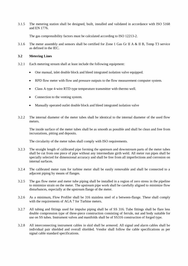
3.1.5 The metering station shall be designed, built, installed and validated in accordance with ISO 5168
and EN 1776.
The gas compressibility factors must be calculated according to ISO 12213-2.
3.1.6 The meter assembly and sensors shall be certified for Zone 1 Gas Gr II A & II B, Temp T3 service
as defined in the IEC.
3.2 Metering Lines
3.2.1 Each metering stream shall at least include the following equipment:
One manual, inlet double block and bleed integrated isolation valve equipped.
RPD flow meter with flow and pressure outputs to the flow measurement computer system.
Class A type 4-wire RTD type temperature transmitter with thermo well.
Connection to the venting system.
Manually operated outlet double block and bleed integrated isolation valve
3.2.2 The internal diameter of the meter tubes shall be identical to the internal diameter of the used flow
meters.
The inside surface of the meter tubes shall be as smooth as possible and shall be clean and free from
incrustations, pitting and deposits.
The circularity of the meter tubes shall comply with ISO requirements.
3.2.3 The straight length of calibrated pipe forming the upstream and downstream parts of the meter tubes shall be cut from one piece of pipe without any intermediate girth weld. All meter run pipes shall be
specially selected for dimensional accuracy and shall be free from all imperfections and corrosion on
internal surfaces.
3.2.4 The calibrated meter runs for turbine meter shall be easily removable and shall be connected to a
adjacent piping by means of flanges.
3.2.5 The gas flow meter and meter tube piping shall be installed in a region of zero stress in the pipeline
to minimize strain on the meter. The upstream pipe work shall be carefully aligned to minimize flow
disturbances, especially at the upstream flange of the meter.
3.2.6 As a minimum, Flow Profiler shall be 316 stainless steel of a between-flange. These shall comply
with the requirements of AGA 7 for Turbine meters.
3.2.7 All tubing and fittings used for impulse piping shall be of SS 316. Tube fittings shall be flare less
double compression type of three-piece construction consisting of ferrule, nut and body suitable for
use on SS tubes. Instrument valves and manifolds shall be of SS316 construction of forged type.
3.2.8 All interconnecting instrument cables in skid shall be armored. All signal and alarm cables shall be
individual pair shielded and overall shielded. Vendor shall follow the cable specifications as per signal cable standard specifications.

3.2.9 The pressure instruments shall be provided with individual process isolation valves and block and
bleed manifolds.
The design used shall provide maximum reliability, maximum on-line performance and minimum maintenance. Instrument shall be field proven. No prototype instrument shall be supplied.
Technique of measurement used shall be interference free. It shall be immune to other impurities
in the fluid stream.
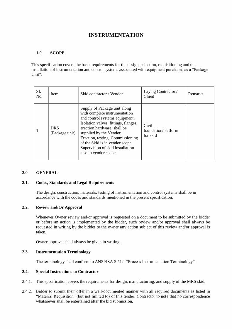
INSTRUMENTATION
1.0 SCOPE
This specification covers the basic requirements for the design, selection, requisitioning and the installation of instrumentation and control systems associated with equipment purchased as a “Package
Unit”.
SI. No.
Item Skid contractor / Vendor Laying Contractor / Client
Remarks
1 DRS (Package unit)
Supply of Package unit along with complete instrumentation
and control systems equipment,
Isolation valves, fittings, flanges,
erection hardware, shall be supplied by the Vendor.
Erection, testing, Commissioning
of the Skid is in vendor scope. Supervision of skid installation
also in vendor scope.
Civil
foundation/platform
for skid
2.0 GENERAL
2.1. Codes, Standards and Legal Requirements
The design, construction, materials, testing of instrumentation and control systems shall be in
accordance with the codes and standards mentioned in the present specification.
2.2. Review and/Or Approval
Whenever Owner review and/or approval is requested on a document to be submitted by the bidder or before an action is implemented by the bidder, such review and/or approval shall always be
requested in writing by the bidder to the owner any action subject of this review and/or approval is
taken.
Owner approval shall always be given in writing.
2.3. Instrumentation Terminology
The terminology shall conform to ANSI/ISA S 51.1 “Process Instrumentation Terminology”.
2.4. Special Instructions to Contractor
2.4.1. This specification covers the requirements for design, manufacturing, and supply of the MRS skid.
2.4.2. Bidder to submit their offer in a well-documented manner with all required documents as listed in
“Material Requisition” (but not limited to) of this tender. Contractor to note that no correspondence
whatsoever shall be entertained after the bid submission.
2.4.3. Bidder’s offer including catalogue, technical literature or any kind of documents shall be in English
language only.
2.4.4. An offer without any of the required documents shall be liable for rejection.
2.4.5. Bidder shall supply the system conforming international standards, which shall be well proven in gas pipeline projects in India and abroad. No prototype system or part of the system shall be supplied.
2.4.6. Bidder is responsible for the selection of the system and / or part of the system so that it shall meet the specifications in Toto. If at any stage, till the completion of the project, the offered system and /
or part of the system are found unsuitable for the specified requirement, bidder shall replace the
same with suitable system meeting the specifications without any time and cost implication.
2.4.7. Bidder may ask for any kind of inputs required to execute their job in a systematic manner. But at the
final stage, bidder shall not get any time extension because of the non-availability of the inputs from
owner.
2.4.8. In case of any conflict between the specifications indicated in same attachment or various
attachments of tender, the same shall be intimated to the owner to resolve before manufacturing.
2.4.9. While submitting engineering documents like data sheets etc. for owner’s approval, bidder must
follow the formats used in tender, although bidder may include any additional data / information in
that data sheet.
3.0 INSTRUMENT IDENTIFICATION
Each instrument shall be identified by unique tag no. as per P&ID.
4.0 DESIGN PRINCIPLES
4.1. General
Instrumentation and control and monitoring systems of Package Units shall be in accordance with this specification and as defined in the P&I Diagrams.
The Package Units shall be supplied complete with all instrumentation, fully piped, wired and tested to ensure safe, reliable and effective operation as well as easy maintenance of the complete Package
Units.
Protection and packing of all materials shall be suitable for shipment and protection on jobsite during storage prior to erection.
4.2. Instrument Selection
Instruments and instrumentation systems of proven reliability shall be used.
4.3. Tagging
All instruments and instrumentation equipment shall be permanently identified by tags, labels and/or
nameplates. Use of adhesive tapes shall not be allowed.
4.4. Painting
Manufacturer’s standard colors shall be used for all instrumentation equipment in control and
instrument rooms, unless otherwise specified. Field instruments shall be epoxy painted, unless
otherwise specified.
4.5. Transmission Systems
Transmission of the process variables shall generally be by means of electronic or low level signals. The output signal for electronic instruments shall be 4 to 20 mA DC or digital. As far as possible, a
true two-wire transmission system shall be used.
4.6. Enclosures and Materials
All instruments shall be suitable to withstand the environmental conditions specified for the plant
location.
All parts subject to moisture, fungus growth or insect attack shall be suitably treated (tropicalisation).
Local instrument housings shall be weather-proof (IP 65 minimum) and meet the electrical area
classification requirements.
All parts of instruments exposed to process fluids shall be resistant to corrosion by the corresponding
fluid.
4.7. Electronic Instrumentation in Hazardous Areas
In hazardous areas, Ex-proof instrumentation shall be provided.
All electrical instruments to be installed in hazardous locations shall be certified to ATEX directives
or other international agencies like CSA, UL, FM.
Contacts shall be encapsulated and, if used in intrinsically safe circuits, contacts shall be gold plated.
4.8. R.F. Immunity
All instruments and control systems shall be immune from the effects of any R.F. interference that
may occur at the plant location in accordance with IEC 801 “Electromagnetic compatibility for industrial-process measurement and control equipment”.
4.9. Electrical Power Supply
Electrical power supply shall be provided by vendor through Solar charged battery ( Min.20 watts).
4.10. Instrument Connections
1) In general, process connections on instruments shall be 1/2” NPT.
2) Pneumatic connections shall generally be 1/4” NPT. Larger sizes may be used for special
applications, e.g. for high-speed actuators.
3) Electrical connections on held instruments shall be 1/2” NPT.
4.11. Measuring Units
The metric SI system shall be used for all documents. The following units of measurement as well as
their multiples and sub-multiples, shall be used.
4.11.1. Flow
• Gas Sm3/h (normal 15.56°C; 1.0332 Kg/cm2 A)
4.11.2. Pressure
• Gauge pressure kg/cm2 g
• Absolute pressure kg/cm2 a
• Differential pressure: kg/cm2
4.11.3. Level 0 - 100 % (Process)
4.11.4. Temperature
°C
4.11.5 Heating Value
Kcal/Btu (user selectable)
4.11.6 Analysers
Direct reading (as pH, % O2, ppm, µS, etc.)
4.11.7 Other measurements
• Current: A or mA
• Voltage: V or mV • Power: kW
• Force: N
• Mass: kg or t • Density: kg/m
3
• Time: d or h or s.
4.12 Scales and Charts
1) Temperature instruments shall have scales calibrated in °C.
2) Pressure instruments shall have scales calibrated in kg/cm2 g.
3) Absolute pressure instruments shall have scales calibrated in kg/cm2 a.
4) Charts for all instruments shall be 0 - 100 linear.
5.0 ENGINEERING DOCUMENTATION
The documents and drawings to be prepared by the bidder are listed hereunder. These shall be
submitted for Owner/Owner’s representative approval during engineering stage.
5.1. Documents
As a minimum requirement, the following documents shall be provided, when applicable.
5.1.1. Instrument index
Instrument Index shall include all tag nos. shown in P&lD and it shall be prepared as per enclosed
format (Ref. Appendix 1).
5.1.2. Instrument data sheets
The data sheets shall comprise all necessary technical data associated with the Instruments as per
the enclosed format (Ref. Appendix 3).
5.1.3. Calculation sheets
Calculation sheets for safety relief valves, thermowell velocity calculation shall be provided along
with data sheet. Sizing/ Velocity calculation required for PCV, PSV, SSV, Noise calclulation etc required.
5.1.4. Certification files
They shall contain copies of all electrical safety certificates and all documents applicable to the
safety of electrical equipment installed in hazardous areas.
5.2. Drawings
As a minimum requirement, the following drawings shall be prepared, when applicable.
5.2.1. Process hook-up drawings
The process hook-up drawings shall show installation details for the various instruments, complete
with a schedule of required material as per enclosed standard drawings.
5.2.2. Tubing hook-up drawings
The tubing hook-up drawings shall show installation details for control valves and on-off valves
complete with a schedule of required material as per enclosed standard drawings.
Supplier shall develop the standard hook up drawing for PG, TG, DPG,SSV and regulators as
standard practice and will submit to Owner/Owner’s representative for approval.
6.0 PRESSURE INSTRUMENTS
6.1. Pressure Gauges
Ref. Appendix 3
6.2. Differential Pressure Guage
Ref. Appendix 3.
6.3 Pressure Transmitter
Ref. Appendix 3.
6.4 Pressure Ranges Range shall be selected so that normal pressure be in the middle third of the span, if possible.
Suppressed ranges may be used to obtain better sensitivity where required.
7.0 TEMPERATURE INSTRUMENTS
7.1. Resistance Temperature Detectors (RTD)
Ref. Appendix 3.
7.2 Temperature Gauge
Ref. Appendix 3.
7.3 Temperature Transmitter
Ref. Appendix 3.
8.0 PRESSURE RELIEVING DEVICES
8.1. Pressure Relief Valves
Refer Data sheet of pressure relief valve
9.0 INSTRUMENTATION WIRING
9.1 Cables
The instrumentation cables shall be selected in function of the application on basis of Appendix 4.
9.2 Earthing
Earthing of instruments, panels, consoles, shall be carried out by others in accordance with the applicable code requirements. Contractor shall provide only connectivity; supply of earth pits is
excluded from contractor’s scope.
CONTROL VALVES
1.0 GENERAL
1.1 Scope
1.1.1 This specification, together with the data sheets attached herewith forms the requirements for the design, materials, nameplate marking, testing and shipping of control valves.
1.1.2 The related standards referred to herein and mentioned below shall be of the latest editions prior to the date of the purchaser's enquiry:
IEC - 79 Electrical Apparatus for Explosive Gas Atmosphere.
IEC - 529 Degree of Protection Provided by Enclosures.
ASME B 1.20.1 Pipe Threads
ASME B 16.5 Steel Pipe Flanges and Flanged fitting.
ASME B 16.20 Ring Joint gaskets and grooves for Steel Pipe Flanges
API 6D Pipelines valves (Gate valve, Plug, Ball and check Valves)
API 609 Lug and wafer type, Butterfly valves.
EN 14382 Safety devices for gas pressure regulating stations and installations. Gas safety shut-off devices for operating pressure up to 100 bar
EN 61056-1 Specification for performance, design and construction of valve,
regulated sealed type.
ISA S 75.01 Flow Equation for sizing control valves.
ISA S 75.02 Control valve capacity test procedure.
ISA S 75.03 Face to face dimensions for flanged Globe-style control valve bodies.
ISA S 75.04 Face to face dimensions for flangeless control valve.
OSHA Occupational Safety and Health Authority.
DIN 50049 Document on Material testing.
IS-2147 Degree of Protection Provided by Enclosures for Low Voltage Switch
gears and Control gears.
IS-2148 Flame proof Enclosures of Electrical Apparatus.
EN 334 Self Actuated Control Valve.
1.1.3 In the event of any conflict between this specification, data sheets, related standards, codes etc., the
vendor should refer the matter to the Owner/ Owner’s Representative for clarifications and only after
obtaining the same should proceed with the manufacture of the items in question.
1.1.4 In addition to compliance to owner’s specifications in totally, bidder’s extent of responsibility
includes
the following :-
(a) Owner’s data sheets specify the minimum acceptable material for the body and trim of self actuated
control valves. Alternative superior material of construction shall also be acceptable.
(b) Sizing and selection of all self actuated control valves suitable for the indicated fluid flow rate over
the indicated turndown, noise and suitable treatment to limit noise less than 85 dbA.
(c) Bidder to include supply of impulse lines, isolation valves, flame proof, junction boxes & cable
glands.
2.0 VALVE SELECTION
2.1 Body Construction
Pressure Control valves with flanged body only are acceptable.
The minimum pressure control valve body size shall be 1".
The valve body rating should be equal to or better than the flange rating specified in the data
sheets.
The valve shall be suitable for installation in horizontal or vertical lines.
2.2 End Connections
2.3 Unless otherwise mentioned, end connection details shall be as below:-
a) Flanged end connections shall be as per ANSI/ASME B 16.5
b) Flanged face finish shall be serrated concentric to paragraphs 6.3.4.1, 6.3.4.2 and 6.3.4.3 of ANSI B 16.5. The face finish as specified in the data sheets shall have cone serrations
as follows:
Serrated 250 to 500 AARH
125 AARH 125 to 200 AARH
63 AARH 32 to 63 AARH.
c) Ring type joint flanges shall have octagonal grooves as per ANSI B 16.20.
2.3.1 Face-to-face dimensions of Globe type control valves shall be in accordance with ISA S 75.03.
2.3.2 Bottom drains shall be plugged off or blind flanged. When a plug is used, threads shall correspond to ANSI/ASME B 1.20.1 (NPT). Where a flange is used, its dimensions and rating shall correspond to
ANSI/ASME B 16.5.
2.4 Guiding shall be as per Vendors manufacturing standards.
2.5 Valve Materials
Valve Material shall be as shown in data sheet.
2.6 Valve Sizing
Valve shall be sized to give proper control throughout flow range with accuracy as mentioned. 2.7 Noise
The noise level of control valves shall not exceed 85 dB, as measured 1 meter downstream of the
valve within 1m radially from the pipe outside diameter.
2.8 Pressure regulator shall be designed in such a way that inlet pressure does not come in direct contact
with the main valve diaphragm (i.e. loading type of regulator only shall be acceptable).
2.9 Regulator shall be designed as per EN 334 and SSV shall be as per EN 14382.
3.0 Finish
3.1 The body shall be painted as below: Carbon steel body - Light grey
Alloy steel body - Canary yellow
Stainless Steel body - Natural
3.2 All the pneumatic valve accessories of the valve shall be weatherproof to IP-65 as per IEC- 529 / IS-
2147.
4.0 NAMEPLATE
4.1 Each control valve shall have a SS nameplate attached firmly to it at a visible place, furnishing the following information:
a) Tag number as per purchaser's data sheet.
b) Body and port sizes in inches. c) Stem travel in millimeters.
d) Action on air failure.
e) Spring range. f) Air supply pressure.
g) Manufacturer's model number for the valve body, actuator and positioner.
5.0 INSPECTION AND TESTING
Unless otherwise specified, purchaser reserves the right to test and inspect all the items at the
vendor's works.
5.1 Vendor shall submit following test certificates and test reports for purchaser's review ;
a) Material test certificate with detailed chemical analysis from the foundry (MIL certificates)
for each casting.
b) Certificate of radiography/x-ray for valve castings. 100% Radiography shall be carried out
for the following valve castings: i) Body sizes 18 inches and above.
ii) Body rating ANSI 300 pounds and above.
c) Pneumatic test certificate for all pneumatic actuator at a pressure not less than one and half (1.5) times the actuator design pressure.
d) Test certificate for each valve giving detail of hydrostatic tests, calibration/stroke checks,
seat leakage tests, valve characteristics, testing of accessories etc.
5.2 Hydrostatic Test
Each control valve body shall be subjected to hydrostatic test at 1.5 times the design pressure as per ANSI rating, all control valve bodies covered under IBR, shall be tested as per IBR regulation. There
shall not be any visible leakage during this test.
5.3 Functional Tests
5.3.1 Seat Leakage Test The test shall meet the requirements specified in ANSI B 16.104.
5.3.2 Lift Characteristics
The test shall be carried out at no load condition and following shall be verified;
a) Stroke Checks.
b) Linearity and Hysteresis Linearity and Hysteresis shall be better than _+ 1.5% of rated lift with positioner and ±5.0%
without positioner.
5.3.3 Certificate from statutory bodies for intrinsic safety/explosion proof and weather proof for
Positioners, limit switches etc. IBR certification in form III C shall also be furnished wherever
applicable.
PRESSURE RELIEF VALVE
1.0 GENERAL
1.1 Scope
1.1.1 This specification, together with the data sheets attached herewith covers the requirements for the design, materials, fabrication, nameplate marking, inspection, testing and shipment of pressure relief
valves.
1.1.2 The related standards referred to herein and mentioned below shall be of the latest editions prior to
the date of the purchaser's enquiry: -
ANSI/ASME American National Standards Institute/American Society for Mechanical
Engineers.
B 1.20.1 Pipe Threads General Purpose (Inch).
B 16.5 Pipe Flanges and Flanged Fittings NPS 1/2" through JSr PS 24
B 16.20 Ring Joint Gaskets and Grooves for Steel Pipe Flange
B 16.34 Valves- Flanged, Threaded and Welding End
ASME American Society of Mechanical Engineers.
Sec-VIII Boiler and Pressure Vessels Code Section VIII 'Pressure Vessels'
Sec-I Boiler and Pressure Vessels Code. Section-! 'Power Boilers'
API American Petroleum Institute
API 520 Sizing, Selection and Installation of Pressure Relieving Devices in
Refineries.
Part I Sizing & Selection
Part II Installation
API 521 Guide for Pressure Relieving and Depressurizing Systems.
API 526 Flanged Steel Pressure Relief Valves
API 527 Seat Tightness of Pressure Relief Valves.
EN 10204 Inspection Documents For Metallic Products.
IBR Indian Boiler Regulations
1.1.3 In the event of any conflict between this specification, data sheets, related standards, codes etc., the
following order of priority shall govern:
a) Statutory Regulations
b) Data Sheets
c) Standard Specification
d) Codes and Standards
1.1.4 In addition to compliance to owner's specifications in totality, bidder's extent of responsibility shall
include the following;
a) Technical data sheets indicate the type, size, relieving area etc. of the selected the valve. However, vendor shall be responsible to size and select the proper valve with orifice relieving
area meeting the indicated operating conditions
b) Technical data sheets specify the minimum acceptable materials for body, bonnet, disc, nozzle, spring, bellows etc. The same shall be finalized during detail engineering.
C) Sizing calculation sheet of valve
1. 2 Drawing and Data
1.2.1 Detailed drawings, data, catalogues and manuals required from the bidder are indicated by the
owner in vendor data requirement sheets.
1.2.2 Final documentation consisting of design data, installation manual, operation and maintenance
manual etc. submitted by the bidder after placement of purchase order shall include the following as a minimum:
a) Specification sheet for each pressure relief valve and its accessories
b) Certified drawing sheets for each pressure relief valve and accessories, which shall provide dimensional details, internal construction details, end connection details, weight and material of
construction.
c) Copy of type test certificates. d) Copy of test certificates for all the tests indicated in clause 3.0 of this specification.
e) Installation procedure for Pressure relief valve and its accessories
f) Calibration and maintenance procedure including replacement of internals wherever applicable.
2.0 DESIGN AND CONSTRUCTION
2.1 Valve Design
2.1.1 The definitions of various terminologies used in purchaser's data sheets are as per API RP 520 part
1.
2.1.2 Unless specified otherwise, all pressure relief valves shall be full nozzle full lift type and all relief
valves in thermal safety application shall be modified nozzle type.
2.1.3 For flanged pressure relief valves, the valve inlet and outlet size, the orifice designation and
corresponding relieving area shall be as per API 526.
2.2 Valve Sizing
2.2.1 Sizing shall be carried out using the formulae mentioned in the following standards whenever the sizing code mentioned in the purchaser's data sheets refers to these
Sizing Code Standard
API API RP 520 Part I API RP 521
2.2.2 Discharge Co-efficient
For all valves in gas, vapour or steam service with design code as ASME Sec VIII or ASME Section I
discharge co-efficient of 0.975 as per API 520 shall be used.
2.2.3 For the selected orifice letter designation and inlet and outlet size of the pressure relief valve, relieving area of the valve offered by vendor shall meet those in API-526.
2.3 Valve Construction
2.3.1 Body
2.3.1.1 Unless otherwise mentioned, end connection details shall be as below: -
a) Threaded end connections shall not be used.
b) Flanged end connections shall be as per ANSI/ASME B 16.5.
c) Flanged face finish shall be as per ANSI/ASME B 16.5.The face finish as specified in the data sheets, shall be as follows;
125AARH 125to200AARH
63 AARH 32 to 63 AARH
2.3.1.2 For flanged valves, inlet and outlet sizes and ratings and centre to flange face dimensions shall
be in accordance with API-526. Dimensional tolerance shall be as mentioned therein.
2.3.1.3 Body drain with a plug shall be provided as a standard feature on every pressure relief valve.
2.3.1.4 For the pilot operated pressure relief valves, where vendor's standard model provides only semi nozzle design (i.e. the body is part of the inlet flow path), body material shall be of the same
material as that of nozzle specified in purchaser's data sheets, as a minimum.
2.3.2 Trim material shall be finalized based on relieving temperature of valve.
2.3.2.1 The term 'trim' covers all the parts of the valves exposed to and in contact with the process fluid
except for the body and bonnet assembly i.e. nozzle, disc, disc holder, stem etc.
2.3.2.2 Valves shall be of the full nozzle type of design with the exception as per clause 2.3.1.4 and valves
in thermal relief application.
2.3.2.3 Wherever stelliting of disc and nozzle has been specified, it stands for stelliting of the seat joint and
the entire disc contour, unless otherwise mentioned.
2.3.2.4 For high temperature application, the materials for the internals shall be selected to avoid galling.
2.3.2.5 Resilient seat, seals or o-rings wherever used shall be suitable for pressure and temperature conditions specified.
2.3.2.6 Gaskets wherever used shall be metallic type. Gaskets with asbestos filler or with asbestos bearing material shall not be used.
2.3.3 Bonnet and Spring
2.3.3.1 All valves shall be provided with a cap over the adjusting bolt. Cap shall be of either bolted type or
screwed type as specified in the purchaser's data sheets.
2.3.3.2 Lifting lever shall be provided whenever the fluid to be relieved is steam and air or water above
65°C.
2.3.3.3 Valve spring shall be selected such that it can permit an adjustment of ±5% of the set pressure, as a
minimum.
2.3.3.4 Carbon steel springs shall be made corrosion resistant through plating/coating as per manufacturer's
standard design or as specified in the purchaser's data sheets.
2.3.3.5 The allowable tolerance in set pressures are as below:
a) ±0.14 kg/cm2 g for set pressure upto and including 5kg/cm
2 g.
b) ±3% for set pressure above 5kg/cm2 g.
2.3.3.6 Bonnet shall be of the closed type for all process applications in general. Open type bonnet shall be
used only for steam and non-hazardous/non-toxic fluids. For all steam applications under design
code 1BR or ASME Section-I with open bonnet design, weather protection cover shall be provided.
2.3.4 Pilot Design
2.3.4.1 For pilot operated valves, the pilot design shall be of inherently fail safe.
2.3.4.2 Unless specified otherwise, pilot shall be non-flowing type.
2.3.4.3 All accessories like back flow preventer, pilot filter etc. required for proper operation of pilot
operated valves as per indicated service conditions shall be included.
2.3.4.4 Material of construction of pilot shall be same as that of main valve nozzle as a minimum.
2.3.4.5 The o-ring and diaphragm material of pilot shall be suitable for the pressure and temperature conditions specified in the data sheet.
2.4 NAMEPLATE
Each pressure relief valve shall have a stainless steel nameplate attached firmly to it at a visible
place furnishing the following information: -
Tag number as per purchaser's data sheet.
Manufacturer's serial number and/or model number.
Manufacturer's name/trade mark.
Nominal flange size in inches and rating in pounds for both inlet and outlet.
Orifice letter designation.
Valve set pressure.
Cold bench test set pressure.
2.4.1 For the above, pressures shall be marked in the same units as those followed in purchaser's data
sheets.
3.0 INSPECTION AND TESTING
3.1 Bidder shall submit the following test certificates and test reports for purchaser's review:-
a) Material test certificate as per clause 3.1B of EN10204 for each valve body and bonnet
castings/forging, nozzle and as per clause 2.2 for stem, disc etc.
b) Certificate of radiography/X-ray for valve castings as per following requirements;
i) 100% radiography shall be carried out for all valve castings with body rating of 600# and
above
or wherever specifically indicated for in the material requisition.
ii) Radiography procedure shall be as per ANSI B 16.34 and acceptance criteria shall be as per
ANSI B 16.34 Annexure-B. Following area of pressure relief valve shall be radiographed
unless specified otherwise.
Inlet flange neck
Outlet flange neck
Nozzle (in case of cast construction)
Body/bonnet joint neck.
c) Dimensional, hydrostatic and functional test reports for all valves
d) Type test certificate for blow-off and closing down pressure.
3.2 Hydrostatic Test
3.2.1 Each Pressure relief valve body shall undergo hydrostatic test as per outlet flange ANSI rating.
However all the safety valves castings covered under IBR shall be tested as per IBR regulations.
There shall not be any visible leakage during this test.
3.2.2 For full nozzle type of pressure relief valve, nozzle shall undergo hydrostatic test as per inlet flange
ANSI rating. For Semi nozzle design, valve Inlet shall be tested after assembly as per Inlet flange ANSI rating.
3.3 Functional Test
3.3.1 Cold bench set pressure test:
Pressure relief valve shall be tested for opening at specified set pressure. Testing of pressure relief valves shall be with air or nitrogen, testing of thermal relief valves shall be with water.
3.3.2 Seat Leakage test
a) Whenever the specified set pressure is less than or equal to 420 kg/cm
2g, the valve shall meet the seat
tightness requirements specified in API RP-527. The maximum permissible leakage rates against
various sizes shall be as specified therein. Whenever the specified set pressure exceeds 420 kg/cm2g,
the vendor shall submit the leakage rates of valves for approval by the purchaser. Where bubble
tightness has been specified, there shall be no leakage or bubbles of air at the specified percentage of
set pressure.
b) Seat leakage test pressure shall be as per API RP 527 for all valves except for valves under IBR or
ASME Section-I design code and pilot operated pressure relief valves. For these valves seat leakage
shall be carried out at the following pressure;
i) Valves Under IBR or ASME Section-I : 95% of Set Pressure
ii) Pilot operated Pressure relief valves
Upto 3.5 Kg/cm2G : 90% of set Pressure
Above 3.5 Kg/cm2G : 95% of Set Pressure
RTD AND THERMOWELSS
1.0 INTRODUCTION
1.1 Scope
1.1.1 This specification, together with the data sheets attached herewith covers the requirements for the design, materials, nameplate marking, inspection, testing and shipping of thermo-couples, RTDs and
Thermowells.
1.1.2 The related, standards referred to herein and mentioned below shall be of the latest editions prior to
the date of the purchaser's enquiry:-
ANSI/ASME B 16.5 Pipe Flanges & Flanged Fittings
ANSI/ASME B 16.20 Metallic Gaskets for Pipe Flanges
B 1.20.1 Pipe Threads General Purpose (Inch) B16.34 Valves Flanged, Threaded and Welding End
Sec-VIII Boiler & Pressure vessel code rules for construction of Pressure vessels
API American Petroleum Institute
RP 551 Recommended Practice 551 -Process Measurement Instrumentation.
PTC 19.3 Performance Test Code-Temperature measurement Inspection Documents
For Metallic Products.
IEC -60079 Industrial Platinum Resistance Thermometer Sensor
IEC 60529 Thermocouple Tolerances
IEC 60751 Specification for Low Voltage Switch gears and Control gears.
IEC 60854-2 Flame proof Enclosures for Electrical Apparatus for Explosive Gas
IS-2148 Atmospheres - Flameproof Enclosures 'd'.
IS-7358 Specifications for Thermocouples
ISA Instrumentation, Systems and Automation Society.
MC 96.1 Thermocouple Tolerances.
1.1.3 In the event of any conflict between this standard specification, job specification, datasheets, statutory regulations, related standards, codes etc. the following order of priority shall govern:
a) Statutory Regulations b) Data Sheets
c) Standard Specification
d) Codes and Standards
1.1.4 In addition to compliance to owner's specifications, bidder's extent of responsibility shall include the
following:
a) Data sheets indicate the minimum acceptable material of construction for sensing element,
thermowell etc. Alternate superior material of construction shall also be acceptable provided
vendor assumes complete responsibility for the selected materials for their compatibility with
the specified fluid and its operating conditions.
b) Bidder shall carry out the vibration analysis of thermowell as per ASME PTC 19.3 standard
and shall provide suitable design for the thermowells wherever necessary.
2.0 DESIGN AND CONSTRUCTION
Resistance Temperature Detectors
2.1.1 The type of RTD shall be as specified in purchaser's data sheet. In general RTD shall be 4 wire, Class
A type with platinum element having 100 ohms resistance at 0°C, selected for temperature range of (-)200 to 650°C.
2.1.2 The element shall be of highly refined material of reference grade and shall have been stress relieved.
RTD calibration shall be as per IEC-60751 -2.
2.1.3 The wire shall be wound on a ceramic core and immobilized against strain or damage. The winding
shall be of bifilar type. The leads shall be copper up to terminal block.
2.1.4 The element shall be within a metal sheath, in a manner which provides good thermal transfer and
protection against moisture. The sheath material shall be 316 Stainless Steel, unless otherwise
specified.
2.1.5 The RTD assemblies shall be furnished with threaded heads. The heads shall consist of a case,
screwed on cover and terminal block. The RTD shall be screwed to the terminal block. Separate screw shall be provided on the terminal block for terminating the incoming cable. There shall be an
extra terminal in the terminal block connected to the head for grounding the shield.
2.1.6 The case shall he suitable for mounting terminal blocks for single or duplex type RTD element
assemblies. The connecting terminals shall be properly numbered and shall be permanently and
legibly identified.
2.1.7 The RTD assemblies shall be spring loaded.
2.1.8 A heat resistant and moisture proof gasket shall be fitted between the case and cover. The head support chain (between case and cover) shall be of stainless steel.
2.1.9 Unless otherwise specified, the assembly shall confirm to the following standards:
a) The heads shall be weather proof to IP-55 as per IEC-60529/IS-13947.
b) In case of flame proof construction, heads shall be flame proof as per IS-60079/IS-2148 & weather proof to IP-55 as per IEC-60529/IS-13947.
2.2 Thermowells
2.2.1 Unless otherwise specified, the thermowell material shall be 316 Stainless Steel.
2.2.2 Thermowells with immersion length up to 500 mm shall be machined out of forged bar-stock. Built-up thermowell with welded wall construction shall be acceptable for immersion length of greater than
500 mm, unless specified otherwise in purchaser's datasheet.
2.2.3 Thermowell flange material and rating shall be as specified in the data sheet.
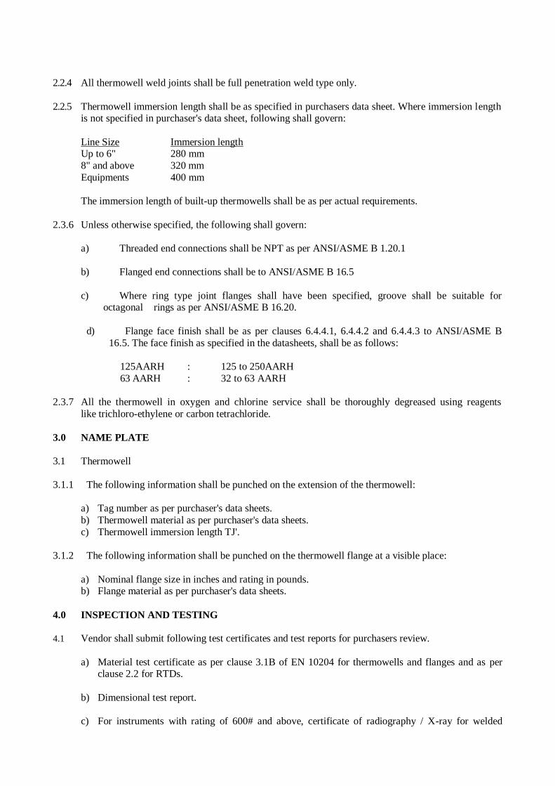
2.2.4 All thermowell weld joints shall be full penetration weld type only.
2.2.5 Thermowell immersion length shall be as specified in purchasers data sheet. Where immersion length is not specified in purchaser's data sheet, following shall govern:
Line Size Immersion length Up to 6" 280 mm
8" and above 320 mm
Equipments 400 mm
The immersion length of built-up thermowells shall be as per actual requirements.
2.3.6 Unless otherwise specified, the following shall govern:
a) Threaded end connections shall be NPT as per ANSI/ASME B 1.20.1
b) Flanged end connections shall be to ANSI/ASME B 16.5
c) Where ring type joint flanges shall have been specified, groove shall be suitable for octagonal rings as per ANSI/ASME B 16.20.
d) Flange face finish shall be as per clauses 6.4.4.1, 6.4.4.2 and 6.4.4.3 to ANSI/ASME B
16.5. The face finish as specified in the datasheets, shall be as follows:
125AARH : 125 to 250AARH
63 AARH : 32 to 63 AARH
2.3.7 All the thermowell in oxygen and chlorine service shall be thoroughly degreased using reagents
like trichloro-ethylene or carbon tetrachloride.
3.0 NAME PLATE
3.1 Thermowell
3.1.1 The following information shall be punched on the extension of the thermowell:
a) Tag number as per purchaser's data sheets.
b) Thermowell material as per purchaser's data sheets.
c) Thermowell immersion length TJ'.
3.1.2 The following information shall be punched on the thermowell flange at a visible place:
a) Nominal flange size in inches and rating in pounds. b) Flange material as per purchaser's data sheets.
4.0 INSPECTION AND TESTING
4.1 Vendor shall submit following test certificates and test reports for purchasers review.
a) Material test certificate as per clause 3.1B of EN 10204 for thermowells and flanges and as per clause 2.2 for RTDs.
b) Dimensional test report.
c) For instruments with rating of 600# and above, certificate of radiography / X-ray for welded
joints. Dye penetration test certificate shall be provided for joints where Radiograph / X-ray is not
possible.
d) Certificate for concentricity of bore.
e) Hydrostatic test report as per clause 4.3 of this specification.
f) Calibration report for RTD's.
g) Certificate from any statutory authority for explosion proof and weatherproof
h) construction of RTD's head as applicable.
4.2 Hydrostatic Test
4.2.1 Each thermowell made of bar stock or built-up type shall be subjected to hydrostatic test for a time
period of 20 minutes at the following pressures:
a) Inside of the well at 100 kg/cm2 upto 600# flange rating and at 200 kg/cm2 above 600# or up to
flange rating whichever is higher b) Outside of the well as per ANSI flange rating.
During and after the hydrostatic test, the thermowell shall not show any leaks or rupture.
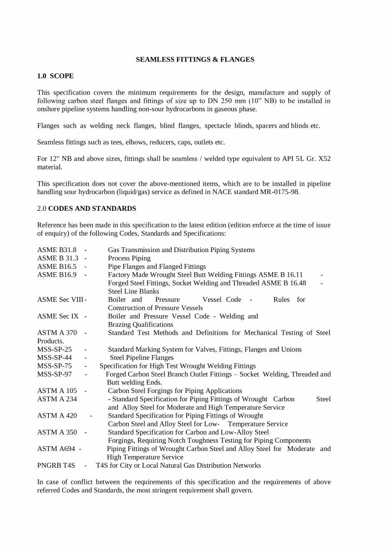
SEAMLESS FITTINGS & FLANGES
1.0 SCOPE
This specification covers the minimum requirements for the design, manufacture and supply of
following carbon steel flanges and fittings of size up to DN 250 mm (10” NB) to be installed in onshore pipeline systems handling non-sour hydrocarbons in gaseous phase.
Flanges such as welding neck flanges, blind flanges, spectacle blinds, spacers and blinds etc.
Seamless fittings such as tees, elbows, reducers, caps, outlets etc.
For 12" NB and above sizes, fittings shall be seamless / welded type equivalent to API 5L Gr. X52
material.
This specification does not cover the above-mentioned items, which are to be installed in pipeline handling sour hydrocarbon (liquid/gas) service as defined in NACE standard MR-0175-98.
2.0 CODES AND STANDARDS
Reference has been made in this specification to the latest edition (edition enforce at the time of issue
of enquiry) of the following Codes, Standards and Specifications:
ASME B31.8 - Gas Transmission and Distribution Piping Systems
ASME B 31.3 - Process Piping
ASME B16.5 - Pipe Flanges and Flanged Fittings ASME B16.9 - Factory Made Wrought Steel Butt Welding Fittings ASME B 16.11 -
Forged Steel Fittings, Socket Welding and Threaded ASME B 16.48 -
Steel Line Blanks ASME Sec VIII - Boiler and Pressure Vessel Code - Rules for
Construction of Pressure Vessels
ASME Sec IX - Boiler and Pressure Vessel Code - Welding and
Brazing Qualifications ASTM A 370 - Standard Test Methods and Definitions for Mechanical Testing of Steel
Products.
MSS-SP-25 - Standard Marking System for Valves, Fittings, Flanges and Unions MSS-SP-44 - Steel Pipeline Flanges
MSS-SP-75 - Specification for High Test Wrought Welding Fittings
MSS-SP-97 - Forged Carbon Steel Branch Outlet Fittings – Socket Welding, Threaded and Butt welding Ends.
ASTM A 105 - Carbon Steel Forgings for Piping Applications
ASTM A 234 - Standard Specification for Piping Fittings of Wrought Carbon Steel
and Alloy Steel for Moderate and High Temperature Service ASTM A 420 - Standard Specification for Piping Fittings of Wrought
Carbon Steel and Alloy Steel for Low- Temperature Service
ASTM A 350 - Standard Specification for Carbon and Low-Alloy Steel Forgings, Requiring Notch Toughness Testing for Piping Components
ASTM A694 - Piping Fittings of Wrought Carbon Steel and Alloy Steel for Moderate and
High Temperature Service
PNGRB T4S - T4S for City or Local Natural Gas Distribution Networks
In case of conflict between the requirements of this specification and the requirements of above
referred Codes and Standards, the most stringent requirement shall govern.
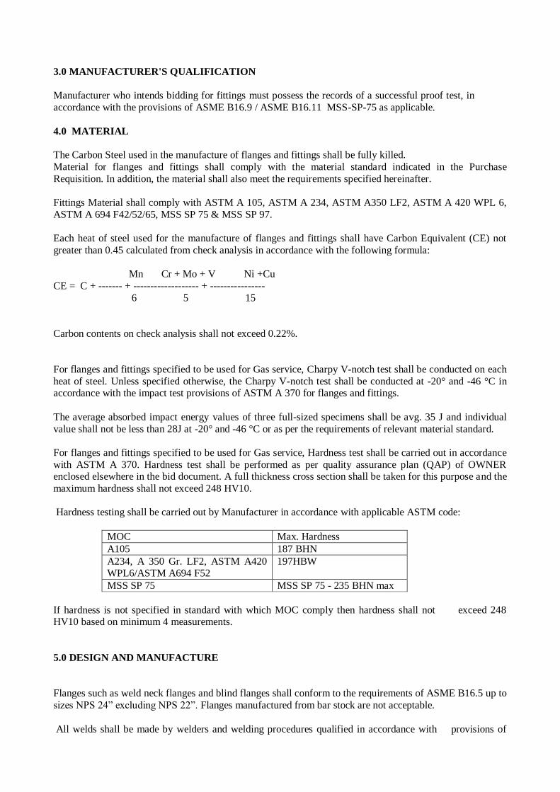
3.0 MANUFACTURER'S QUALIFICATION
Manufacturer who intends bidding for fittings must possess the records of a successful proof test, in
accordance with the provisions of ASME B16.9 / ASME B16.11 MSS-SP-75 as applicable.
4.0 MATERIAL
The Carbon Steel used in the manufacture of flanges and fittings shall be fully killed.
Material for flanges and fittings shall comply with the material standard indicated in the Purchase
Requisition. In addition, the material shall also meet the requirements specified hereinafter.
Fittings Material shall comply with ASTM A 105, ASTM A 234, ASTM A350 LF2, ASTM A 420 WPL 6,
ASTM A 694 F42/52/65, MSS SP 75 & MSS SP 97.
Each heat of steel used for the manufacture of flanges and fittings shall have Carbon Equivalent (CE) not
greater than 0.45 calculated from check analysis in accordance with the following formula:
Mn Cr + Mo + V Ni +Cu
CE = C + ------- + ------------------- + ----------------
6 5 15
Carbon contents on check analysis shall not exceed 0.22%.
For flanges and fittings specified to be used for Gas service, Charpy V-notch test shall be conducted on each
heat of steel. Unless specified otherwise, the Charpy V-notch test shall be conducted at -20° and -46 °C in accordance with the impact test provisions of ASTM A 370 for flanges and fittings.
The average absorbed impact energy values of three full-sized specimens shall be avg. 35 J and individual
value shall not be less than 28J at -20° and -46 °C or as per the requirements of relevant material standard.
For flanges and fittings specified to be used for Gas service, Hardness test shall be carried out in accordance
with ASTM A 370. Hardness test shall be performed as per quality assurance plan (QAP) of OWNER enclosed elsewhere in the bid document. A full thickness cross section shall be taken for this purpose and the
maximum hardness shall not exceed 248 HV10.
Hardness testing shall be carried out by Manufacturer in accordance with applicable ASTM code:
MOC Max. Hardness
A105 187 BHN
A234, A 350 Gr. LF2, ASTM A420 WPL6/ASTM A694 F52
197HBW
MSS SP 75 MSS SP 75 - 235 BHN max
If hardness is not specified in standard with which MOC comply then hardness shall not exceed 248 HV10 based on minimum 4 measurements.
5.0 DESIGN AND MANUFACTURE
Flanges such as weld neck flanges and blind flanges shall conform to the requirements of ASME B16.5 up to
sizes NPS 24” excluding NPS 22”. Flanges manufactured from bar stock are not acceptable.
All welds shall be made by welders and welding procedures qualified in accordance with provisions of
ASME Sec. IX. The procedure qualification shall include Charpy V-notch test for weld/heat affected zone
and hardness test.
Repair by welding on flanges and parent metal of Flanges is not permitted. Repair of weld seam by welding shall be carried out by welders and welding procedures duly qualified as per ASME Section IX and records
for each repair shall be maintained. Repair welding procedure qualification shall include all tests, which are
applicable for regular production welding procedure qualification.
All flanges shall be furnished in the heat treated condition. Hot formed flanges shall be cooled below the
lower critical temperature prior to heat treatment.
Fittings shall be made by forging, hammering, pressing, piercing, rolling, extruding, upsetting, welding, or
by a combination of these operations. The forming procedure shall be so applied that it will not produce
injurious defects.
Fittings not covered in ASME B16.5, 16.9 and 16.11 like weld-o-lets, sock-o-lets etc. shall be manufactured
in accordance with MSS SP 97 and in accordance with Manufacturer's recommendation
Fittings such as tees, elbows, reducers, etc. shall be seamless type and shall conform to ASME B16.9 for
sizes DN 50 mm (2") and above ASME B16.11 for sizes below NPS 2”.
Spectacle blind and spacer & blind shall conform to the requirements of ASME B 16.48.
Fittings such as weldolets, sockolets, nippolets, etc. shall be manufactured in accordance with MSS-SP-97.
All butt weld ends shall be bevelled as per ASME B 16.5 / ASME B 16.9 / MSS-SP- 97 as applicable.
Type, face and face finish of flanges shall be as specified.
Flanges and fittings manufactured from bar stock are not acceptable.
Repair by welding on flanges and fittings are not permitted.
Stub-in or pipe to pipe connection shall not be used in the manufacture of tees.
Tees shall be manufactured by forging or extrusion methods. Fittings shall not have any circumferential
joint.
6.0 INSPECTION AND TESTS
6.1
The Manufacturer shall perform all inspections and tests as per the requirement of
quality assurance plan (enclosed elsewhere in the bid document), this specification and the relevant codes, prior to shipment at his works. Such inspections and tests shall be,
not but limited to the following :
a) All flanges and fittings shall be visually inspected. The internal and external surfaces
of the flanges and fittings shall be free from any strikes, gauges and other detrimental
defects.
b) Dimensional checks shall be carried out on finished products as per ASME B16.5 for
flanges, ASME B16.48 for spacers and blinds and ASME B16.9 / MSS-SP-97 as
applicable for fittings and as per this specification.
c)
Chemical composition and mechanical properties shall be checked as per relevant material standards and this specification, for each heat of steel used.
d)
e)
All finished wrought weld ends subject to welding in field, shall be 100% tested for
lamination type defects by ultrasonic test. Any lamination shall not be acceptable
irrespective of their size and length at bevel areas.
All other inspection shall be carried out as per quality assurance plan attached elsewhere
in the bid as minimum.
6.2
Purchaser's Inspector reserves the right to perform stage wise inspection and witness tests,
as indicated in clause 6.1 of this specification at Manufacturer's Works prior to shipment. Manufacturer shall give reasonable notice' of time and shall provide, without charge,
reasonable access and facilities required for inspection, to the Purchaser's Inspector.
Note: NDE inspector & procedures shall be qualified in accordance with ASME Sec. V,
Article 5. The evidence of such records shall be furnished by Manufacturer to OWNER /
TPI on request. Minimum qualification of NDE Inspector shall be ASNT Level-II certification.
Inspection and tests performed / witnessed by Purchaser's Inspector shall in no way relieve the Manufacturer's obligation to perform the required inspection and tests.
7.0
TEST CERTIFICATES
Manufacturer shall furnish the following certificates:
Test certificates relevant to the chemical analysis and mechanical properties of the materials used for
manufacture of flanges and fittings as per relevant standards and this specification.
Test Reports on non destructive testing.
Certificates for each fitting stating that it is capable of withstanding without leakage a test pressure,
which results in a hoop stress equivalent to 100 % of the specified minimum yield strength for the
pipe with which the fitting is to be attached without impairment of serviceability.
8.0 PAINTING, MARKING AND SHIPMENT
After all inspection and tests required have been carried out; all external surfaces shall be thoroughly
cleaned to remove grease, dust and rust and shall be applied with standard mill coating for protection against
corrosion during transit and storage. The coating shall be easily removable in the field.
Ends of all fittings and weld neck flanges shall be suitably protected to avoid any damage during transit.
Metallic or high impact plastic bevel protectors shall be provided for fittings and flanges. Flange face shall be suitably protected to avoid any damage during transit.
All flanges and fittings shall be marked as per applicable dimension / manufacturing standard.
Ends of all fittings shall be suitably protected to avoid any damage during transit. Metallic bevel protectors
shall be used for fittings and each item shall be marked with indelible paint with the following data:
Manufacturer name / trademark Material specification
Size and schedule/wall thickness
Heat Number Package shall be marked legibly with suitable marking ink to indicate the following:
Order Number
Package number
Manufacturer’s Name/trademark
Type of fitting
Size and wall Thickness/schedule
9.0 DOCUMENTATION
Documentation to be submitted by Manufacturer to Company is summarized below. Number of Copies (Hard copies / soft copies etc.) shall be as indicated in CONTRACT document / Material Requisition.
At the time of bidding, Manufacturer shall submit the following documents:
Reference list of previous supplies of similar fittings of similar specification.
Clause wise list of deviations from this specification, if any.
Brief description of the manufacturing and quality control facilities at Manufacturer's works. Manufacturer's qualification requirement as per clause 3.0 of this specification.
Quality Assurance Plan (QAP) enclosed with this tender duly signed, stamped and accepted.
Prior to shipment, the Manufacturer shall submit test certificates as listed in clause
7.0 of this specification.
All documents shall be in English Language only.
10.0 WARRANTY
Warranty Type
Manufacturer shall give warranty stating that the fittings comply with the requirements stated in this
specification and the other relevant standard & codes. Manufacturer is bound to replace or repair all fittings, which are found defective due to inadequate engineering or to the quality of materials and machining or any
other reasons at no extra cost to OWNER.
If fittings defects cannot be eliminated, Manufacturer shall replace the same without any delay.
Manufacturer will reimburse OWNER for any fitting furnished on the order that fails under field hydrostatic test if such failure is caused by a defect in the fitting, which is outside the acceptance limits of this
specification. The reimbursement cost shall include fitting, labor and equipment rental for finding,
excavation, cutting out, and installation of replaced fitting in position. The field hydrostatic pressure will not exceed that value which will cause a calculated hoop stress equivalent to 100% of SMYS for the pipe with
which the fitting is to be attached without impairing its serviceability.
Warranty validity
The above warranty shall be valid for any defect occurring during the first year of operation, but not later
than 24 months from the date of shipment from Manufacturer's works. All expenses shall be to Manufacturer's account.
FABRICATION & INSTALLATION
I GENERAL
1.0 SCOPE
This specification covers general requirements of fabrication and installation of aboveground
and underground piping systems at site. The specification covers the scope of work of contractor, basis of work to be carried out by contractor and standards, specifications and normal practice to be followed during fabrication and erection by the contractor. Its scope is essentially the same as that of ASME Code B31.3. This specification shall apply to all piping installed by or pre-fabricated for installation by CONTRACTOR.
The welded pipe joints shall include the following and shall not relieve the contractor of his responsibilities and guarantee. a) All pipe joints, longitudinal butt welds, circumferential butt welds and socket welds.
b) Attachments of forging, flanges and other supports to pipes.
c) Welded manifold headers and other sub assemblies.
d) Welded branch connections with or without reinforcing pads.
e) Joints in welded / fabricated piping components.
f) The attachments of smaller connection for vents drain drips and other instrument tapings. 2.0 CODES AND STANDARDS
Unless otherwise stated the design of piping systems shall confirm to the requirement of
latest edition of following Codes and Standards. i) AWS (American Welding Society). a) A2.4 (Symbols for Welding and Non destructive Testing). b) A3.0 (Standard Welding Terms and their Definitions). c) A5.1 (Specification for Mild Steel Covered Arc Welding Electrodes). d) A 5.17(Specification for Bare Carbon Steel Covered Electrodes). e) A 5.18 (Specification for Carbon Steel Filler Metals for Gas Shielded Arc Welding). f) A 5.20 (Specification for Mild Steel Electrodes for Flux Cored Arc Welding Electrodes). iI) ASME B31.8 - Gas Transmission and Distribution piping systems iiI) ASME B31.3 - Process piping for refineries and chemical plant and
terminals. iV) API 1104 - Standard for Welding Pipelines and related facilities. v) API 1105 - Bulletin on construction practices for oil and products
pipelines. vi) OISD 118 - Layout of Oil & Gas Installations vii) API 598 - Valve Inspection and Test
viii) ASME Sec. VIII Div. 1 – Boiler and Pressure Vessel Code – Rules for Construction of
Pressure Vessels
ix) ASME Sec. IX - Boiler and Pressure Vessel Code - Welding and Brazing Qualifications
x) PNGRB T4S - T4S for City or Local Natural Gas Distribution Networks
PNGRB NOTIFICATION: Technical Standards and specifications including safety standards for city or local natural gas distribution Schedule-1 network
All welding procedures used by fabricators and CONTRACTORS shall have been established and qualified in accordance with the appropriate sections of one or more of the codes and standards listed above, and approved by the OWNER.
Where a conflict occurs between these specifications and / or any of the above codes or standards the more stringent shall apply.
Dimensional Standards
Flanges - ASME B16.5, B 16.47 Welding Fitting - ANSI B16.9, B16.11 Pipe - ANSI B36.10 Gaskets - ANSI B16.20, B16.21 Butt Weld Ends - ANSI B 16.25 Spec. for line pipe - API 5L Valves – Flanged, Threaded end Welding end - ASME B 16.34 In the event of any conflict between the requirements of this specification and any code/ standard, the most stringent requirement shall be followed.
II PIPING FABRICATION
1.0 GENERAL
Fabrication and erection of all piping systems by CONTRACTOR shall be in accordance
with this specification and applicable drawings and standards. a) Fabrication and erection of supporting elements i.e. shoes, guides, stop anchors, clips,
cradles etc, shall include applying one coat of epoxy red oxide zinc phosphate primer (Minimum DFT 100µ) and two coat of final painting of high build epoxy paint 125µ for each coat.
b) Fabrication and erection of supporting fixtures i.e. brackets, cantilever struts etc. shall include application of one coat of epoxy red oxide zinc phosphate primer (Minimum DFT 100µ) and two coat of final painting of high build epoxy paint (Min. 125µ per coat)
c) Fabrication and erection of drain assemblies The contractor shall fabricate all pipe work in conformity with the requirements of pertinent general arrangement drawings and specifications where specific details of fabrication are not indicated on the drawings or not specified, herein, fabrication and erection shall be done in accordance with ASME B 31.3/ ASME B 31.8 latest edition.
2.0 CUTTING
Following shall be applied for all cutting works: 2.1 For laying out headers, tees, laterals and other irregular details, cutting templates shall be
used to ensure accurate cutting and proper fit-up. 2.2 Machine cut bevels to form the welding groove are preferred in carbon steel pipe. However,
smooth, clean, slag free false cut bevels are acceptable.
2.3 Cutting of pipes may be done either by mechanical means or by thermal cutting. Whenever cutting is employed all oxides and traces of previously melted metal and occasional notches shall be removed from edges by grinding or machining.
2.4 Pipe cutting is to be performed using sawing only for galvanized, stainless steel and copper nickel materials.
2.5 Cutting shall be made with suitable allowance taken in to account for shape of connections and shrinkage due to cutting and welding.
2.6 All cutting shall follow the outline of the templates.
2.7 Special care shall be taken to remove internal burrs resulting from cutting especially on pipes equal to or less than 2” NPS in diameter.
3.0 WELDING
3.1 Welders shall be qualified in accordance with the Welding Specification ENG-STD-PI-DOC-
TS-009 and other applicable standards i.e. ASME SEC. IX.
3.2 The joints to be field welded shall be beveled as per ASME B 16.25.
3.3 Adjacent sections of longitudinally welded pipe that are joined by butt-welding shall have the longitudinal weld seams positioned so that they are at least 30 degrees apart from the horizontal centerline.
3.4 Wherever possible, longitudinal weld seam should not be located on the top or bottom of the line so that branch connections are not positioned on the seam.
3.5 No backings strips/ rings shall be used.
3.6 Welding shall be is per approved as per Welding Procedure Specification (WPS) and Procedure Qualification Record (PQR).
3.7 Non-Destructive Testing (NDT) such as Radiography Testing (RT), Ultrasonic Testing (UT), etc. should be carried out, after Post Weld Heat Treatment (PWHT).
3.8 Tack welds with full penetration shall be used and shall become the part of the finished weld, defection welds or tack welds with lack of penetration are not acceptable and shall be chipped/ ground out.
4.0 INTERNAL MISALIGNMENT
The pipes to be joined by welding shall be aligned correctly with existing tolerances on diameters, wall thickness and out of roundness. The same alignment shall be preserved during welding for the internal misalignment due to difference in wall thickness of the mating components exceeding 1/16”; the component with higher wall thickness shall be internally machined/ grounded so that the adjoining surfaces are approximately flushed.
4.1 Internal misalignment shall be as per the criteria set out in ASME B 31.3 and as per the following guidelines:
a) 24" NPS and smaller pipe-to-pipe fitting: 1.5mm maximum deviation.
b) Greater than 24” pipe-to-pipe or pipe-to-fitting: 3.2mm maximum Deviation when permitted
by the relevant WPS.
c) Dimensional tolerances for the fabrication and installation of piping systems shall be ± 1/8 inch and ± 2 degrees. Misalignment of flange faces and welding ends shall be limited to 3/64 inch per foot measured across any diameter.
4.2 If the deviation factors are exceeded, one of the following procedures shall be used:
a) Rotate the pipe or fittings to reduce misalignment to the acceptable tolerances (before
attempting any of the following methods) allowing for seam alignment.
b) Use spreaders or internal or external line-up clamps to correct moderate out-of- round Condition.
c) Taper the wall of the component internally after obtaining approval from OWNER for the
proposed method and ensure wall thickness is not reduced below the minimum required by the ASME B 31.8 code.
d) If allowable deviations are exceeded beyond repair methods, the fabrication shall be
redone.
4.3 All flange facing shall be true and perpendicular to the axis of the pipe to which they are attached. Flange bolt holes shall span the normal center lines unless different orientation is shown in drawings to match the equipment connections etc.
5.0 FLANGES
Flange bolt holes are to be oriented as follows, unless otherwise indicated in the fabrication drawings:
5.1 Flange faces vertical - bolt holes to straddle vertical centerline.
5.2 Flange faces horizontal - bolt holes to straddle the horizontal plane centerline.
5.3 Where line taps are called for, the hole shall be drilled square to the axial centerline clean, sharp, free from burrs, wire edges, or other irregularities. The hole shall be drilled after first attaching the connection fitting.
5.4 Where slip-on flanges are called for, they shall be welded inside and outside (See Figure 328.5.2B of ASME B 31.3). The weld shall be applied so that the flange face shall be free of weld spatter and does not require facing.
5.5 Orifice flanges shall be installed with the taps in the exact orientation shown in the isometric. The sections of pipe to which the orifice flanges are attached may be standard mill run pipe, but shall be choice selected pieces and shall be round, smooth and free from blisters and scale. The interior of the pipe, at welds, shall he ground smooth, Welds to be performed on site shall be kept at a maximum distance hack from the face of the orifice flange.
6.0 NON PRESSURE ATTACHMENTS
6.1 The CONTRACTOR shall be responsible for working to the exact dimensions as shown on
the drawings irrespective of individual tolerances permissible. Where errors and/ or omissions occur on the drawings, it shall the Contractor's responsibility to notify the Engineer-in-charge prior to fabrication or erection.
6.2 Non-pressure attachments shall he installed in accordance with the isometric and any
supplemental data provided by the detailed engineering CONTRACTOR.
6.3 Piping requiring post weld heat treatment shall have all welded-on non-pressure attachments installed by the shop fabricator. Piping not requiring post-weld heat treatment may have the welded-on non-pressure attachments installed by the installation CONTRACTOR. If field welding is required on post weld heat-treated piping, then localized field post weld heat treatment shall be done after welding as approved by the OWNER.
7.0 FABRICATION TOLERANCES
7.1 The CONTRACTOR shall be responsible for working the exact dimensions as shown on the
drawings irrespective of individual tolerances permissible. Where errors and/ or omissions occur on the drawing it shall be the contractor’s responsibility to notify the OWNER prior to fabrication or erection.
7.2 Thinning of Wall Thickness and Quality in Bends.
The maximum decrease of wall thickness shall not exceed 10% of the nominal wall thickness as specified in the line classes and in any case shall not be less than that required by the design.
The tolerances for the maximum flattering of a bend shall be per ASME B 31.3 section 332.2.
7.3 Flange Face Alignment The maximum deviation measured in any direction shall not exceed 2.5mm. When branches are in the same plane and their flanges are also positioned in one plane, the flange facings shall not deviate more than 1 mm from the latter plane in the same direction.
7.4 Position of Bolt Holes for Flanged Piping The maximum deviation allowed from the required position as measured along the bolt circle is 1.5mm.
7.5 Field-Fit Weld Where the requirement is called for in the isometric, a field-fit weld is used when the exact piping dimension cannot be predetermined, to allow the installation CONTRACTOR adjustability of two spool pieces. 150mm to be added the calculated length of one of the spools. The installation CONTRACTOR is to verity the dimension before trimming and beveling. The isometric will indicate only the calculated length.
7.6 Pup-pieces installed to make-up a spool length shall be a minimum of (2) pipe diameters long or 150mm which ever is higher unless stated otherwise by the OWNER.
8.0 EXAMINATION AND INSPECTION
8.1 Examination and Inspection shall be as per NDT Specification of document No. ENG-STD-
PI-DOC-TS-011
8.2 In case of fillet welds where carrying out radiography is not possible, magnetic particle test or dye penetrant test shall be carried out. The extent of inspection shall be same as for radiography. Finished weld shall also he visually inspected for parallel and axial misalignment of the work, cracks, inadequate penetration and shall present neat workman like appearance.
8.3 All the lines, which are stress relieved or have design pressure more than 50 kg/cm2 shall be fully radiographed (100%)
9.0 SURFACE PREPARATION AND PAINTING
Applicable surface preparation and painting shall be in accordance with painting
Specification document No. ENG-STD-PI-DOC-TS-008 attached elsewhere in the bid document.
10.0 PROTECTION, PRESERVATION AND STORAGE
Piping shall be protected as follows:
10.1 After fabrication, flange faces shall be cleaned, coated with rust preventative, & protected with non-metallic flange covers, secured to the flange prior to erections/ installation/ shipment. Other methods and products for flange protection may be acceptable, subject to OWNER approval.
10.2 Socket-weld connections shall be cleaned and plugged, or capped with metal or plastic
protectors.
10.3 The open ends of pipe shall be protected with metal or plastic caps.
10.4 A metal cap secured by a steel strap around the pipe shall be used to protect open end "O-lets".
10.5 Fabricated spool pieces shall be carefully loaded with the proper amount of tonnage and ample tie-downs to protect each piece during shipping. Tie-downs shall be nylon straps; chains or cable are prohibited.
10.6 Adequate protection shall be provided to prevent mechanical damage and atmospheric corrosion in transit and at the job site.
10.7 Fabricated spool pieces and materials shall be protected to withstand ocean transit and extended period of storage at the job site for a minimum period of 18 months. Fabricated spool pieces and piping components shall be protected to safeguard against all adverse environments, such as humidity, moisture, rain, dust, dirt, sand, mud, salt air, salt spray, and seawater.
10.8 Field weld joints shall be coated and wrapped as per specification.
III PIPING INSTALLATION
1.0 GENERAL
Unless specified otherwise, the piping in general shall:
1.1 Be run level and plumb.
1.2 All piping shall be fabricated and installed to the configurations as shown in the Isometric.
1.3 Be run on the North-South and East-West axis
2.0 ERECTION
The intent of pre-fabrication at the shop is to accelerate progress of pipe work and to
minimize work in the field. Such prefabrication should be based on approved isometric and piping layouts furnished to the CONTRACTOR. Field weld is indicated by "FW" on isometrics. Field weld means position weld of prefabricated piece at site or near the plant.
However the contractor shall bear in mind that there can be variations in dimensions
between those appearing at the site due to minor variations in the location of equipment, inserts etc. The CONTRACTOR shall, therefore, provide adequate field joints, if required, other than shown in isometrics and fit-in sections permitting the pre-assembly to be installed without any modification.
All piping shall be routed and located as shown in piping drawings keeping in view the
piping specifications. While fitting up mating flanges, care shall be exercised to properly align the pipes and to
check the flanges for trueness, so that faces or the flanges can be pulled up together without inducing any stresses on the pipes. The bolt holes of flanges in the vertical plane shall straddle the vertical center line of the pipe in the erected position and for flanges in the horizontal plane, the bolt holes shall straddle horizontal plane unless otherwise indicated on the drawings.
The CONTRACTOR shall maintain slopes specified for various lines in the drawings. In
case the CONTRACTOR is unable to maintain the indicated slope he shall check the sagging of the pipe with a precision spirit level. Vents and drains are shown in the isometric of each line and these are intended, during hydrostatic test for releasing the trapped air and draining out the test fluid after testing. Valves vents and drains are also shown wherever required.
Where practicable and except when otherwise shown on the drawings, valve stems shall
be installed in a vertical direction and shall not be installed with stems below the horizontal axis.
3.0 UNDERGROUND PIPING
3.1 Underground piping shall be laid according to piping general arrangement drawing Issued during the course of construction
3.2 Pipeline trenches shall be dug wherever necessary according to drawing, true to line and
gradient as per specification 3.3 No excavation material shall be deposited within 1.5m from excavated trench.
3.4 Coated pipes shall not be placed in trenches until sharp, hard stones, skids, welding rods
etc. have been removed. 3.5 Coated pipe shall not be handled or moved by means of cables or chains or by prying. 3.6 With skids or bars, it shall be tied and lowered by using lowering-in belts of a Standard Width
for the size of pipe being used. 3.7 Coated pipe shall not be dragged along the ground or otherwise handled in a manner that
will be detrimental to its coating. 3.8 Backfilling with the excavated material shall be done in layers of 200 mm. well watered and
rammed to avoid settling afterwards.
4.0 FLANGE BOLTING
4.1 Use a logical sequence of bolt tightening to ensure even gasket compression, as indicated in
ANSI B16.5. 4.2 Prior to bolt up, inspect flange faces. Flange faces shall be in “as-new" condition and shall
be wiped clean of any debris excess oil or grease and dirt. Do not perform weld repairs on flange faces or flanges.
4.3 Do not use washers or spacers to make-up bolt length. Bolt lengths are specified prevent
over sizing. 4.4 While fitting up mating flanges, care shall be exercised to properly align the pipes and check
the flanges for trueness, so flanges can be pulled together without inducing stresses at pipes.
5.0 JOINTS
The relevant piping class will be assigned to each line identified on the isometric. In
general, joining for lines 2" and above in utility piping system shall be accomplished by butt-welding connections. Pipe lines of size 1½” and below shall have socket welded/butt welded/screwed joints as specified in the piping materials specifications.
5.1 Do not apply insulation over any joints until testing has been completed.
5.2 Gaskets on flanged joints shall be used only once.
5.3 Gaskets shall be selected in accordance with Piping Materials.
6.0 SUPPORTS
6.1 Installation of supports shall be as indicated in the isometric / support piping layouts.
6.2 Supports, guides and anchors for piping shall be fabricated and provided as shown in the
drawings. No anchors on piping shall be used except at locations shown in the drawings. The pipe shall be secured firmly at anchor supports.
6.3 Fabrication and erection of supporting elements and structural fixtures wherever required
whether indicated in drawings or not, to prevent vibration, excess sag etc. shall be carried out by the CONTRACTOR.
6.4 Erection of these additional supports will be deemed as part of piping erection work scope. 7.0 CLEANLINESS OF PIPING
7.1 On completion of fabrication, all pipes and fittings shall be cleaned inside and outside by
suitable means (mechanical cleaning tool, Wire brush, etc.) before erection to ensure that assembly is free from all loose foreign materiel such as scale, sand, weld spatter particles, cutting chips etc.
7.2 All field fabricated piping shall also be cleaned at the completion of the fabrication. All burrs,
welding circles and weld spatter shall be removed by any suitable means (mechanical tools, wire brush etc.).
7.3 Both shop and field fabricated piping shall be blown out with compressed air at the
termination of cleaning and capped. 7.4 Open end and flanges protection shall be used throughout installation. Protect open pipes
at all times when work on them is not actually taking place. 7.5 Inspect individual pipe section, prefabricated spools and pipeline items internally during
installation and remove any foreign matter before final welding or bolting. 7.6 Adjoining Piping with special equipment or piping within a packaged, vendor provided
"skid", which requires cleaning in accordance with the equipment’s Manufacturer’s procedures, shall be inspected by, and have cleaning supervised by, the Manufacturer’s representative.
8.0 INSTALLATION PROCEDURE FOR SOCKET WELDED SMALL BORE VALVES
As well as complying with all applicable code requirements for quality and strength of the
weld, it is necessary to avoid damage to soft seats and distortion of "small bore" valve bodies by excessive heat input.
a) Process The process to be used shall be manual metal arc, metal inert gas or CO2 with preference
for the lower heat input high deposition (dip transfer) processes. Gas welding shall not be used because of its excessive heat input.
b) Preparation Ensure that valve is in open position. Correctly locate and align the pipe in the valve socket
with a clearance of approximately 1.6 mm (1/16 inch) between the end of the pipe and the bottom of the socket.
c) Procedure Deposit the first run of weld metal around the pipe.Deposit metal for making additional runs
as required, ensuring that each run of weld metal is cleaned and any visible defects such as cracks, cavities or other faults are removed before deposition of further weld metal.
9.0 DRAIN AND VENT CONNECTION
High point vents and low point drains required for the purpose of hydro testing shall be of
size 1” and consist of sockolet, Plug & Ball valve for vent, Globe & Ball Valve for drain, flange & blind flange.
All low points in a line shall be provided with drain connections of nominal size as given in
table below. All drains shall be with valve and blind except for water lines where valves are not required.
10.0 LINE MARKING / IDENTIFICATION
Process and utility type shall be identified stenciled lettering used to identify service and
flow direction. Lettering shall be identified every 10 meters in pipe rack and should be visible from ground level.
IV TESTING
1.0 PIPING
Pressure tests shall be performed as per ANSI B 31.8 latest edition or as per design basis and appropriate piping material specification class chart per Piping Material Specification document No. ENG-STD-PI-DOC-TS-001.
The field test pressure shall not be less than the highest of the following:
a) 1.5 times the design line class pressure. b) 1.5 times the maximum operated pressure c) 1.5 times the maximum pipeline static pressure d) Sum of the maximum sustained operating pressure or maximum operating or maximum
pipe line static pressure and the maximum calculated surge pressure.
The hold period shall be minimum 6 hours. The testing shall be carried out in convenient section as approved by site engineer. The joints of pipe connecting the testing section shall be 100% radiographed and UT tested and shall be tested with other applicable NDT method as specified in specification. If some defects are noticed during the hydrostatic testing, the same shall be brought to the notice of the OWNER. Joints, if leaking, shall be rectified as per welding specification and instructions and tested to the complete satisfaction of the OWNER.
The following items shall not be subjected to field pressure testing
a) Pressure relieving devices such as rupture discs and pressure relief valves.
b) Locally mounted pressure gauges. c) Control valves, shutdown/ isolation valves etc. d) Any other equipment designated by the OWNER.
All the elements, which are not to be tested along with the piping, shall either be blanked
off during testing or spool pieces inserted during testing. Any temporary corrosion protection coating given on piping at manufacturer's shop/
fabrication yard is to be removed at all inspection points, before final testing.
Prior to Hydro testing, vessels and piping are to be flushed by high pressure, high volume fresh water or inhibited water.
Following are the general requirements for testing of piping:
a) Test pressures shall be maintained for a sufficient length of time to permit through inspection of all the joints for a leakage or sign of failure. The duration shall in no case be less than six (6) hours.
b) Instrument take-off piping up to the first block valve shall be tested with the connected
piping.
c) Lines open directly to atmosphere such as vents, drains, safety valve discharge etc. shall be leak tested and all the joints shall be visually inspected.
2.0 MAXIMUM ALLOWABLE VALVE TEST PRESSURE Test pressure applied to valves under closed position shall not be greater than the
manufacturer's recommendations nor less than required API 6D latest edition where the required test pressure is greater than the allowable seat pressure, test shall be made through the 50% open valve.
3.0 HYDROSTATIC TEST FLUID
3.1 Fresh potable water shall be used as the testing medium for hydrostatic testing of piping in fabrication yard and at site.
3.2 The lines shall be completely drained and dried by air immediately after the successful
completion of testing. 3.3 Salt water shall not be used for testing. 3.4 A strainer shall be installed in the line to minimize the possibility of foreign matter being
introduced into the system during the pressure test and flushing operations. 4.0 PNEUMATIC TESTING
4.1 Pneumatic testing of instrument air, utility air, starting air and instrument gas piping shall be performed with compressed air. The test pressure shall be 110% of design pressure or 49 bar (g) whichever is higher in case of 300# rating piping.
4.2 In addition to hydro test, all the station piping shall be pneumatic tested. The test pressure
shall be per clause 4.1 above. 4.3 When pneumatic testing at over 25 psi, a preliminary test at 25 psi shall be made to locate
major leaks. Then the pressure shall be increased gradually to test pressure.
5.0 TEST PROCEDURE
5.1 All events and other connections, which serve as vents, shall be open during filling so that all air is vented prior to applying test pressure to the system.
5.2 Gauges used for testing shall be installed as close as possible to the highest point of the piping system.
5.3 Care shall be exercised to avoid increase in pressure due to temperature variation during
the test. 5.4 After completion of the recorded test pressure recorder, the pressure shall be reduced to
the design pressure and all valves, including check valves, in the section of the line shall be tested by being closed for a ten (10) minutes period with pressure contained by specific valve at one end and by positive closure at the other to determine whether each valve is in turn positively shutting off and holding pressure.
5.5 After completion of hydrostatic test, the pressure shall be released gradually in steps. All
the vents and drains shall be kept open till the lines are fully drained. The CONTRACTOR shall then dry the system by blowing compressed dry air and reinstall items removed during Hydrotesting.
5.6 Record shall be made of each piping system during the testing. These records shall be
prepared in tabulated foams and shall include. a) Date of Test
b) Identification of piping and equipment tested with medium
c) Test medium
d) Test Pressure
e) Test Duration
f) Acceptance of Test Results by OWNER
g) Calibration certificates of test gauges, recorders and PSV's. 5.7 Testing shall be deemed as complete only after defects noticed during testing have been
rectified and testing of the system / line has been done to the satisfaction of the OWNER's representative.
5.8 The CONTRACTOR shall supply all plain test blanks required for the pressure testing. 5.9 Gauges and pressure recorders used for testing shall be calibrated at a reputed laboratory
at least every 6 months. 5.10 Temporary supports shall be provided wherever required during testing to the satisfaction of
OWNER.
INSPECTION, FLUSHING & TESTING
1.0 SCOPE
This specification covers the general requirements for inspection, flushing and testing of piping systems. Flushing and testing of all piping systems shall be witnessed by the owner/ consultant. 2.0 CODES AND STANDARDS
ASME B31.8 : Gas Transmission and Distribution piping systems
PNGRB T4S : T4S for City or Local Natural Gas Distribution Networks
3.0 INSPECTION
During various stages and after completion of fabrication and erection, the piping system shall be inspected by the Engineer-In-Charge to ensure that:
- Proper piping material has been used. - Piping has been erected as per drawings and instructions of Engineer-In-Charge. - All supports have been installed correctly. - Test preparations mentioned in this specification have been carried out.
4.0 FLUSHING
Flushing of all lines shall be done before pressure testing. Flushing shall be done by fresh potable water or dry compressed air, wherever water flushing is not desirable, to clean the pipe of all dirt, debris or loose foreign material Required pressure for water flushing shall meet the fire hydrant pressure or utility water pressure. For air flushing, the line / system will be pressurized by compressed air at the required pressure which shall be 50 psi maximum. The pressure shall then be released by quick opening of a valve, already in line or installed temporarily for this purpose. This procedure shall be repeated as many times as required till the inside of the pipe is fully cleaned.
In line instruments like control valves, orifice plates, rotameters, safety valves and other instruments like thermowells which may interfere with flushing shall not be included in flushing circuit. The screens / meshes shall be removed from all permanent strainers before flushing. Screens/meshes shall be reinstalled after flushing but before testing.
During flushing temporary strainers shall be retained. These shall be removed, cleaned and reinstalled after flushing but before testing. In case of equipment such as column, vessel, exchanger etc. form part of a piping circuit during flushing, this shall be done with the approval of Engineer-In-Charge. However, equipments thus included in the circuit shall be completely drained and dried with compressed air after flushing is completed. During flushing discharged water/air shall be drained to the place directed by the Engineer-In-Charge. If necessary, proper temporary drainage shall be provided by the contractor. Care shall be taken during flushing so as not to damage/spoil work of other agencies. Precautions shall also be taken to prevent entry of water/foreign matter into equipments, electric motors, instruments, electrical installations etc. in the vicinity of lines being flushed. The contractor shall carry out all the activities required before, during and after the flushing operation, arising because of flushing requirements, such as but not limited to the following
Dropping of valves, specials, distance pieces, inline instruments and any other piping part before flushing. The flanges to be disengaged for this purpose shall be envisaged by the contractor and approved by the Engineer-In-Charge. These flanges shall be provided with temporary gaskets at the time of flushing. After flushing is completed and approved, the valve distance pieces, piping specials etc. shall be reinstalled by the contractor with permanent gaskets. However, flanges at equipment nozzles and other places where isolation is required during testing, only temporary gaskets shall be provided. Records in triplicate shall be prepared and submitted by the contractor for each piping system for the flushing done in the Performa provided/approved by the Engineer-in-Charge.
5.0 TESTING
Pressure testing, in general shall be as per requirements of ASME B31.8, unless otherwise specified.
5.1 Extent of Testing
With the exclusion of instrumentation, piping systems fabricated or assembled in the field shall be tested irrespective of whether or not they have been pressure tested prior to site welding of fabrication.
To facilitate the testing of piping systems, vessels and other equipments may be included in the system with the prior approval of Engineer-In-Charge if the test pressure specified is equal to or less than that for the vessels and other equipments.
Pumps, compressors and other rotary equipments shall not be subjected to field test pressure.
Lines which are directly open to atmosphere such as vents, drains, safety valves discharge need not be tested, but all joints shall be visually inspected. Wherever necessary, such lines shall be tested by continuous flow of fluid to eliminate the possibility of blockade. However, such lines if provided with block valve shall be pressure tested up to the first block valve.
Seats of all valves shall not be subjected to a pressure in excess of the maximum cold working pressure of the valve. Test pressure applied to valves shall not be greater than the manufacturer’s recommendation nor less than that required by the applicable code. Where allowable seat pressure is less than test pressure, test shall be made through an open valve. Instruments in the system to be tested shall be excluded from the test by isolation or removals, unless approved otherwise by the Engineer-In-Charge.
Restrictions which interfere with filling, venting and draining such as orifice plates etc. shall not be installed unless testing is complete. Control valves shall not be included in the test system. Where bypasses are provided test shall be performed through the bypass and necessary spool shall be used in place of the control valve. Pressure gauges which are part of the finished system, but cannot withstand test pressure shall not be installed until the system has been tested. Where piping systems to be tested are directly connected at the battery limits to piping for which the responsibility rests with other agencies, the piping to be tested shall be isolated from such piping by physical disconnection such as valve or blinds.
5.2 General Requirements / Test Preparation for Testing
Testing shall be carried out with permanent gaskets installed unless specified otherwise or instructed by the Engineer-in-Charge. No pressure test shall be carried out against closed valve unless approved by the Engineer-in-Charge. The Engineer-in-Charge shall be notified in advance by the Contractor, of the testing sequence and program, to enable him to be present for witnessing the test. Before testing, all piping shall be cleaned by flushing to make it free from dirt, loose scale, debris and other loose foreign materials. All piping systems to be hydrostatically tested shall be vented at the high points and the systems purged of air before the test pressure is applied.
Wherever in the line any void exists due to any reasons, like absence of control valves, safety valves, check valves etc. it shall be filled with temporary spools. All joints welded, screwed or flanged shall be left exposed for examination during the test. Before pressuring the lines, each weld joint shall be cleaned by wire brush to free it from rust and any other foreign matter. Where a system is to be isolated at a pair of companion flanges, a blank shall be inserted between the companion flanges. Minimum thickness of the blank shall be designed in accordance with applicable design code. Open ends of piping system where blanks cannot be used, such as pumps, compressors, turbines or wherever equipment or pipe spools have been recovered or disconnected prior to hydrostatic testing, shall be blinded off by using standard blind flanges of same rating as the piping system being tested.
Pressure gauges used in testing shall be installed as close as possible to the lowest point in the piping system to be tested, to avoid overstressing of any of the lower portions of the system. For longer lines and vertical lines, two or more pressure gauges shall be installed at locations decided by the Engineer-in-Charge. For lines containing check valves any of the following alternatives shall be adopted for pressure testing: Whenever possible pressurize up-stream side of valve. Replace the valve by a temporary spool and reinstall the valve after testing. Provide blind on valve flanges and test the upstream and downstream of the line separately and remove the blind after testing. At these flanges, temporary gaskets shall be provided during testing and shall be replaced by permanent gaskets subsequently. For check valves in lines 1 1/2” and below flapper or seat shall be removed during testing (if possible). After completion of testing the flapper/seat shall be refitted. Gas lines when hydrostatically tested shall be provided with additional temporary supports during testing as directed by the Engineer-in-Charge. Piping which is spring or counter-weight supported shall be temporarily supported, where the weight of the fluid would overload the support. Retaining pins for spring supports shall be removed only after testing is completed and test fluid is completely drained. When testing any piping system, air or steam of approximately 2 kg/cm2 (g) may be used as preliminary test to detect missing gaskets etc. as this avoids the necessity of draining the line to make repairs. However, steam shall not be used for this purpose, if the steam temperature is more than the design temperature of the line. For jacketed pipes testing of core pipes shall be done on individual pieces where the pipe is continuously jacketed, before it is jacketed. The outer jacket shall be tested separately as a system. For piping with discontinuous jacketing the core pipe and the jacket shall be tested as separate continuous systems.
5.3 Testing Media, Test Pressure and Test Pressure Gauges
5.3.1 Testing Media
In general all pressure test shall be hydrostatic using iron free water, which is clean and free of silt. Maximum chlorine content in water for hydrostatic testing for S.S. piping shall be 15-20 PPM. Air shall be used for testing only if water would cause corrosion of the system or overloading of supports etc. in special cases as directed by Engineer-in-Charge. Where air/water tests are undesirable, substitute fluids such as gas oil, kerosene, methanol etc. shall be used as the testing medium, with due consideration to the hazards involved. These test fluids shall be specified in the line list given to the contractor.
5.3.2 Test Pressure
The hydrostatic/pneumatic test pressure shall be as indicated in the line list or as per the instruction of Engineer-in-Charge.
The selection of the piping system for one individual test shall be based on the following:
a. Test pressure required as per line list.
b. Maximum allowable pressure for the material of construction of piping.
Depending upon the above requirements and based on construction progress, maximum length of piping shall be included in each test.
5.3.3 Test Pressure Gauge
All gauge used for field testing shall have suitable range so that the test pressure of the various system
falls in 35% to 65% of gauge scale range. Pressure gage shall be minimum of 150 mm. Size of
Bourdon shall not be less than 75% of nominal diameter of dial range. Gauge shall be of a good
quality and in first class working condition.
Prior to the start of any test or periodically during the field test programmes, all test gauges shall be calibrated using a standard dead weight gauge tester or other suitable approved testing apparatus. Any gauge having an incorrect zero reading or error of more than ± 2% of full scale range shall be discarded. The Engineer-in-charge shall check the accuracy of master pressure gauge used for calibration.
5.4 Testing Procedure 5.4.1 Hydrostatic Test
All vents and other connections used as vents shall be left open while filling the line with test fluid for complete removal of air. In all lines for pressurizing and depressurizing the system, temporary isolating valves shall be provided if valves vents, drains do not exist in the system.
Pressure shall be applied only after the system / line is ready and approved by the Engineer-in- charge.
Pressure shall be applied by means of a suitable test pump or other pressure source which shall be isolated from the system as soon as test pressure is reached and stabilized in the system.
A pressure gauge shall be provided at the pump discharge for guidance in bringing the system to the required pressure.
The pump shall be attended constantly during the test by an authorized person. The pump shall be isolated from the system whenever the pump is to be left unattended.
Test pressure shall be maintained for a sufficient length of time to permit thorough inspection of all joints for leakage or signs of failure. Any joint found leaking during a pressure test shall be retested to the specified pressure after repair. Test period shall be maintained for a minimum of three hours.
The pump and the piping system to be tested are to be provided with separate pressure indicating test gauges. These gauges are to be checked by the standard test gauge before each pressure test.
Care shall be taken to avoid increase in the pressure due to temperature variation during the test.
5.4.2 Air Test
When testing with air, pressure shall be supplied by means of a compressor. The compressor shall be portable type with a receiver, after cooler and oil separator.
Piping to be tested by air shall have joints covered with a soap and water solution so that the joints can be examined for leaks.
All other details shall be same as per hydrotesting procedure (specified above)
5.5 Completion of Testing
After the hydrostatic test has been completed, pressure shall be released in a manner and at a rate so as not to endanger personnel or damage equipments. All vents and drains shall be opened before the system is to be drained and shall remain open till all draining is complete, so as to prevent formation of vacuum in the system. After draining, lines / systems shall be dried by air. After testing is completed the test blinds shall be removed and equipment/ piping isolated during testing shall be connected using the specified gaskets, bolts and nuts. These connections shall be checked for tightness in subsequent pneumatic tests to be carried out by the contractor for complete loop / circuit including equipments (except rotary equipments). Pressure test shall be considered complete only after approved by the Engineer-in-Charge. Defects, if any, noticed during testing shall be rectified immediately and retesting of the system / line shall be done by the contractor at his cost.
5.6 Test Records
Records in triplicate shall be prepared and submitted by the contractor for each piping system, for the pressure test done in the Performa provided/approved by the Engineer-in-Charge.
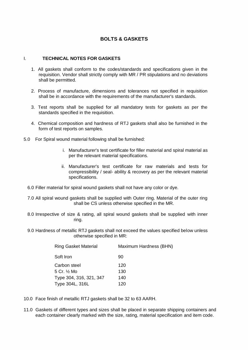
BOLTS & GASKETS I. TECHNICAL NOTES FOR GASKETS
1. All gaskets shall conform to the codes/standards and specifications given in the
requisition. Vendor shall strictly comply with MR / PR stipulations and no deviations
shall be permitted.
2. Process of manufacture, dimensions and tolerances not specified in requisition
shall be in accordance with the requirements of the manufacturer's standards.
3. Test reports shall be supplied for all mandatory tests for gaskets as per the
standards specified in the requisition.
4. Chemical composition and hardness of RTJ gaskets shall also be furnished in the
form of test reports on samples. 5.0 For Spiral wound material following shall be furnished:
i. Manufacturer's test certificate for filler material and spiral material as
per the relevant material specifications.
ii. Manufacturer's test certificate for raw materials and tests for
compressibility / seal- ability & recovery as per the relevant material
specifications.
6.0 Filler material for spiral wound gaskets shall not have any color or dye.
7.0 All spiral wound gaskets shall be supplied with Outer ring. Material of the outer ring shall be CS unless otherwise specified in the MR.
8.0 Irrespective of size & rating, all spiral wound gaskets shall be supplied with inner
ring.
9.0 Hardness of metallic RTJ gaskets shall not exceed the values specified below unless
otherwise specified in MR:
Ring Gasket Material
Soft Iron
Maximum Hardness (BHN)
90
Carbon steel 120
5 Cr. ½ Mo 130
Type 304, 316, 321, 347 140
Type 304L, 316L 120
10.0 Face finish of metallic RTJ gaskets shall be 32 to 63 AARH.
11.0 Gaskets of different types and sizes shall be placed in separate shipping containers and
each container clearly marked with the size, rating, material specification and item code.
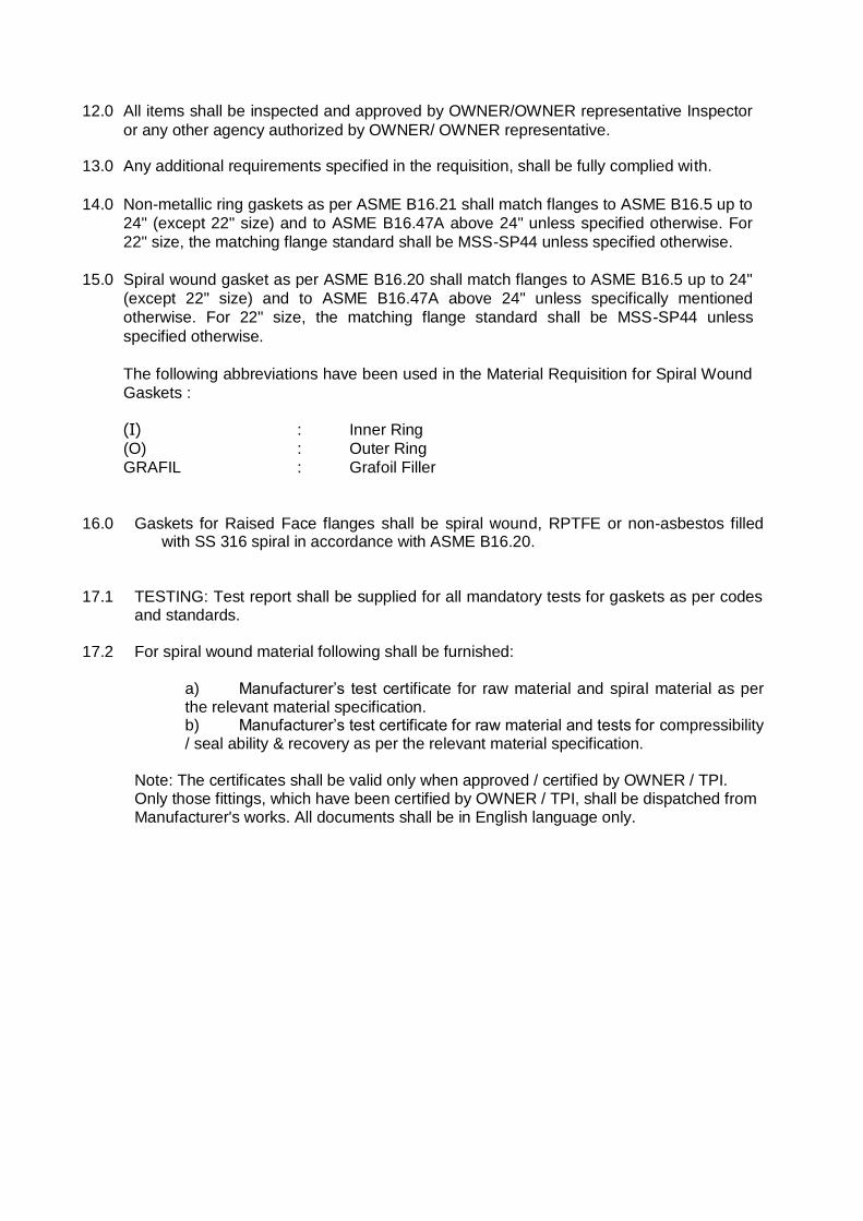
12.0 All items shall be inspected and approved by OWNER/OWNER representative Inspector
or any other agency authorized by OWNER/ OWNER representative. 13.0 Any additional requirements specified in the requisition, shall be fully complied with.
14.0 Non-metallic ring gaskets as per ASME B16.21 shall match flanges to ASME B16.5 up to
24" (except 22" size) and to ASME B16.47A above 24" unless specified otherwise. For
22" size, the matching flange standard shall be MSS-SP44 unless specified otherwise.
15.0 Spiral wound gasket as per ASME B16.20 shall match flanges to ASME B16.5 up to 24"
(except 22" size) and to ASME B16.47A above 24" unless specifically mentioned
otherwise. For 22" size, the matching flange standard shall be MSS-SP44 unless
specified otherwise.
The following abbreviations have been used in the Material Requisition for Spiral Wound
Gaskets :
(I) : Inner Ring
(O) : Outer Ring
GRAFIL : Grafoil Filler
16.0 Gaskets for Raised Face flanges shall be spiral wound, RPTFE or non-asbestos filled
with SS 316 spiral in accordance with ASME B16.20.
17.1 TESTING: Test report shall be supplied for all mandatory tests for gaskets as per codes
and standards. 17.2 For spiral wound material following shall be furnished:
a) Manufacturer’s test certificate for raw material and spiral material as per the relevant material specification. b) Manufacturer’s test certificate for raw material and tests for compressibility / seal ability & recovery as per the relevant material specification.
Note: The certificates shall be valid only when approved / certified by OWNER / TPI. Only those fittings, which have been certified by OWNER / TPI, shall be dispatched from Manufacturer's works. All documents shall be in English language only.
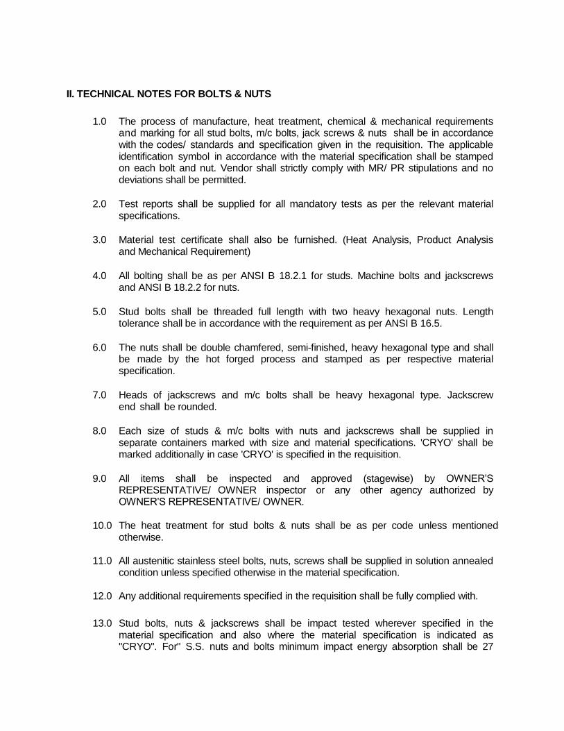
II. TECHNICAL NOTES FOR BOLTS & NUTS
1.0 The process of manufacture, heat treatment, chemical & mechanical requirements and marking for all stud bolts, m/c bolts, jack screws & nuts shall be in accordance with the codes/ standards and specification given in the requisition. The applicable identification symbol in accordance with the material specification shall be stamped on each bolt and nut. Vendor shall strictly comply with MR/ PR stipulations and no deviations shall be permitted.
2.0 Test reports shall be supplied for all mandatory tests as per the relevant material
specifications.
3.0 Material test certificate shall also be furnished. (Heat Analysis, Product Analysis
and Mechanical Requirement)
4.0 All bolting shall be as per ANSI B 18.2.1 for studs. Machine bolts and jackscrews
and ANSI B 18.2.2 for nuts.
5.0 Stud bolts shall be threaded full length with two heavy hexagonal nuts. Length
tolerance shall be in accordance with the requirement as per ANSI B 16.5.
6.0 The nuts shall be double chamfered, semi-finished, heavy hexagonal type and shall
be made by the hot forged process and stamped as per respective material specification.
7.0 Heads of jackscrews and m/c bolts shall be heavy hexagonal type. Jackscrew
end shall be rounded.
8.0 Each size of studs & m/c bolts with nuts and jackscrews shall be supplied in
separate containers marked with size and material specifications. 'CRYO' shall be marked additionally in case 'CRYO' is specified in the requisition.
9.0 All items shall be inspected and approved (stagewise) by OWNER’S
REPRESENTATIVE/ OWNER inspector or any other agency authorized by OWNER’S REPRESENTATIVE/ OWNER.
10.0 The heat treatment for stud bolts & nuts shall be as per code unless mentioned
otherwise. 11.0 All austenitic stainless steel bolts, nuts, screws shall be supplied in solution annealed
condition unless specified otherwise in the material specification. 12.0 Any additional requirements specified in the requisition shall be fully complied with.
13.0 Stud bolts, nuts & jackscrews shall be impact tested wherever specified in the material specification and also where the material specification is indicated as "CRYO". For" S.S. nuts and bolts minimum impact energy absorption shall be 27
Joules and test temperature shall be -196°C unless mentioned otherwise. For other materials impact energy and test shall be as per respective code.
14.0 Bolts / nuts of material of construction A320 L7 and A194 Gr. B7 shall be 100%
hardness tested. Refer QAP attached elsewhere in the bid document for more details.
15.0 When specified as galvanized, the studs, m/c bolts and nuts shall be 'hot dip zinc
coated' in accordance with requirements of 'class C' of 'ASTM A 153'. As an alternative, electro- galvanizing as per IS 1573, 'Service Grade Number 2' is also acceptable.
NDT
1.0 SCOPE
This specification covers the general requirements for non destructive examination of
shop & field fabricated and inspection of all pressure Piping and Distribution Pipeline. 2.0 CODES AND STANDARDS
Referred codes/ standards are as follows. Latest editions of the Codes/ Standards referred to shall be followed.
a) ASME Boiler & Pressure Vessel Codes, Section V & VIII (Div. 1) including addenda.
b) ASME B31.3 Chemical Plant and Petroleum Refinery Piping.
c) ASME 31.8 -Gas Transmission and Distribution Systems.
d) Standard Specification for Fabrication & Installation of Piping
e) ASNT/PCN/CGSB Standards for certification of Non Destructive testing Personnel.
Work shall also be carried out in compliance with all general specification dealing with welding and fabrication of various equipment / piping.
2.1 CONFLICT
Where a conflict occurs between this Specification and any of the above Codes or Standards the more stringent shall apply. The contractor shall inform the OWNER in writing and receive written certification form the OWNER. The contractor shall have readily available for use at the request of the OWNER, latest editions of all codes, specification and standards necessary for execution of the work at work site.
3.0 NDE COMPANY CERTIFICATION
All Non Destructive Examination (NDE) CONTRACTORs contracted by the OWNER, or
working for fabricators or CONTRACTORs carrying out work on the OWNER’s behalf shall have in place an up-to-date Quality Control Manual and Code of Practice which shall cover the following:
i) All aspects of NDE of which the CONTRACTOR / SUB-CONTRACTOR is qualified.
ii) Current resumes of all presently employed personnel including their certifications
(PCN, ASNT, CGSB or equivalent).
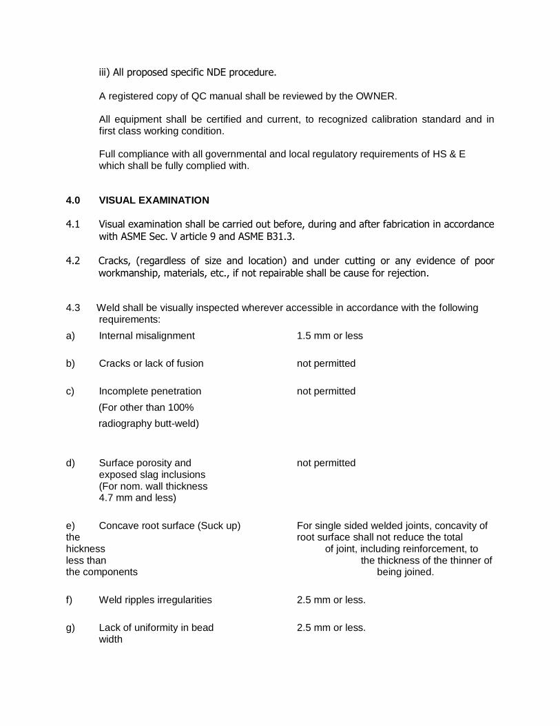
iii) All proposed specific NDE procedure.
A registered copy of QC manual shall be reviewed by the OWNER. All equipment shall be certified and current, to recognized calibration standard and in first class working condition. Full compliance with all governmental and local regulatory requirements of HS & E
which shall be fully complied with.
4.0 VISUAL EXAMINATION
4.1 Visual examination shall be carried out before, during and after fabrication in accordance
with ASME Sec. V article 9 and ASME B31.3. 4.2 Cracks, (regardless of size and location) and under cutting or any evidence of poor
workmanship, materials, etc., if not repairable shall be cause for rejection. 4.3 Weld shall be visually inspected wherever accessible in accordance with the following
requirements:
a) Internal misalignment 1.5 mm or less
b) Cracks or lack of fusion not permitted
c) Incomplete penetration not permitted
(For other than 100%
radiography butt-weld)
d) Surface porosity and not permitted exposed slag inclusions (For nom. wall thickness 4.7 mm and less)
e) Concave root surface (Suck up) For single sided welded joints, concavity of the root surface shall not reduce the total hickness of joint, including reinforcement, to less than the thickness of the thinner of the components being joined.
f) Weld ripples irregularities 2.5 mm or less.
g) Lack of uniformity in bead 2.5 mm or less. width
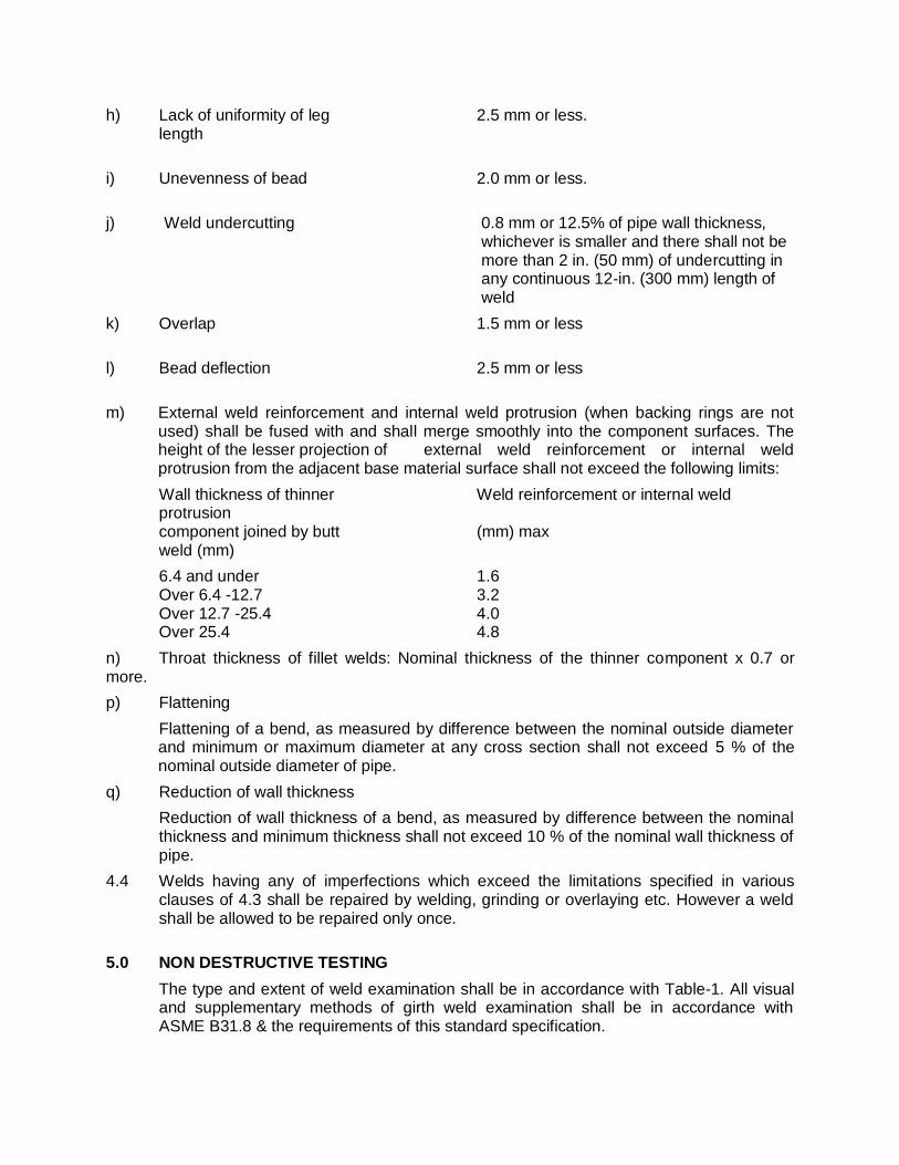
h) Lack of uniformity of leg 2.5 mm or less. length
i) Unevenness of bead 2.0 mm or less.
j) Weld undercutting 0.8 mm or 12.5% of pipe wall thickness, whichever is smaller and there shall not be more than 2 in. (50 mm) of undercutting in any continuous 12-in. (300 mm) length of weld
k) Overlap 1.5 mm or less
l) Bead deflection 2.5 mm or less
m) External weld reinforcement and internal weld protrusion (when backing rings are not used) shall be fused with and shall merge smoothly into the component surfaces. The height of the lesser projection of external weld reinforcement or internal weld protrusion from the adjacent base material surface shall not exceed the following limits:
Wall thickness of thinner Weld reinforcement or internal weld protrusion component joined by butt (mm) max weld (mm)
6.4 and under 1.6 Over 6.4 -12.7 3.2 Over 12.7 -25.4 4.0 Over 25.4 4.8
n) Throat thickness of fillet welds: Nominal thickness of the thinner component x 0.7 or more.
p) Flattening
Flattening of a bend, as measured by difference between the nominal outside diameter and minimum or maximum diameter at any cross section shall not exceed 5 % of the nominal outside diameter of pipe.
q) Reduction of wall thickness
Reduction of wall thickness of a bend, as measured by difference between the nominal thickness and minimum thickness shall not exceed 10 % of the nominal wall thickness of pipe.
4.4 Welds having any of imperfections which exceed the limitations specified in various clauses of 4.3 shall be repaired by welding, grinding or overlaying etc. However a weld shall be allowed to be repaired only once.
5.0 NON DESTRUCTIVE TESTING
The type and extent of weld examination shall be in accordance with Table-1. All visual and supplementary methods of girth weld examination shall be in accordance with ASME B31.8 & the requirements of this standard specification.
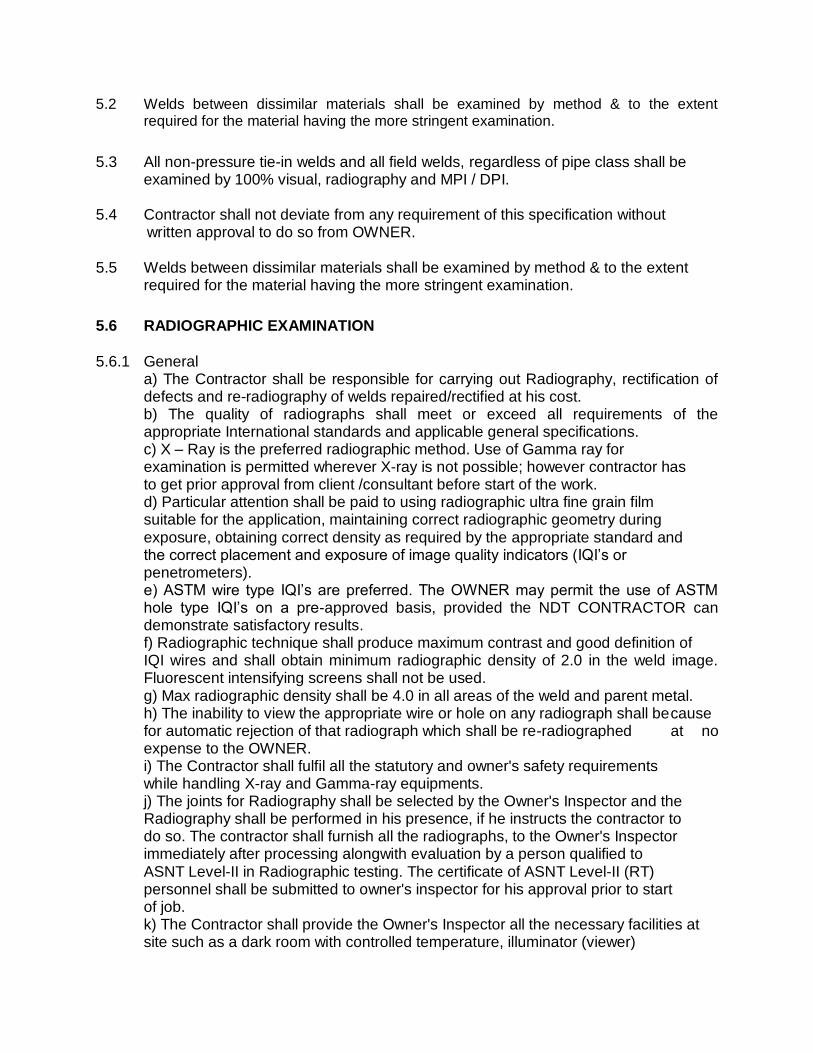
5.2 Welds between dissimilar materials shall be examined by method & to the extent required for the material having the more stringent examination.
5.3 All non-pressure tie-in welds and all field welds, regardless of pipe class shall be examined by 100% visual, radiography and MPI / DPI.
5.4 Contractor shall not deviate from any requirement of this specification without written approval to do so from OWNER. 5.5 Welds between dissimilar materials shall be examined by method & to the extent
required for the material having the more stringent examination.
5.6 RADIOGRAPHIC EXAMINATION
5.6.1 General a) The Contractor shall be responsible for carrying out Radiography, rectification of defects and re-radiography of welds repaired/rectified at his cost. b) The quality of radiographs shall meet or exceed all requirements of the appropriate International standards and applicable general specifications. c) X – Ray is the preferred radiographic method. Use of Gamma ray for examination is permitted wherever X-ray is not possible; however contractor has to get prior approval from client /consultant before start of the work. d) Particular attention shall be paid to using radiographic ultra fine grain film suitable for the application, maintaining correct radiographic geometry during exposure, obtaining correct density as required by the appropriate standard and the correct placement and exposure of image quality indicators (IQI’s or
penetrometers). e) ASTM wire type IQI’s are preferred. The OWNER may permit the use of ASTM hole type IQI’s on a pre-approved basis, provided the NDT CONTRACTOR can demonstrate satisfactory results. f) Radiographic technique shall produce maximum contrast and good definition of IQI wires and shall obtain minimum radiographic density of 2.0 in the weld image. Fluorescent intensifying screens shall not be used. g) Max radiographic density shall be 4.0 in all areas of the weld and parent metal. h) The inability to view the appropriate wire or hole on any radiograph shall be cause for automatic rejection of that radiograph which shall be re-radiographed at no expense to the OWNER. i) The Contractor shall fulfil all the statutory and owner's safety requirements while handling X-ray and Gamma-ray equipments. j) The joints for Radiography shall be selected by the Owner's Inspector and the Radiography shall be performed in his presence, if he instructs the contractor to do so. The contractor shall furnish all the radiographs, to the Owner's Inspector immediately after processing alongwith evaluation by a person qualified to ASNT Level-II in Radiographic testing. The certificate of ASNT Level-II (RT) personnel shall be submitted to owner's inspector for his approval prior to start of job. k) The Contractor shall provide the Owner's Inspector all the necessary facilities at site such as a dark room with controlled temperature, illuminator (viewer)
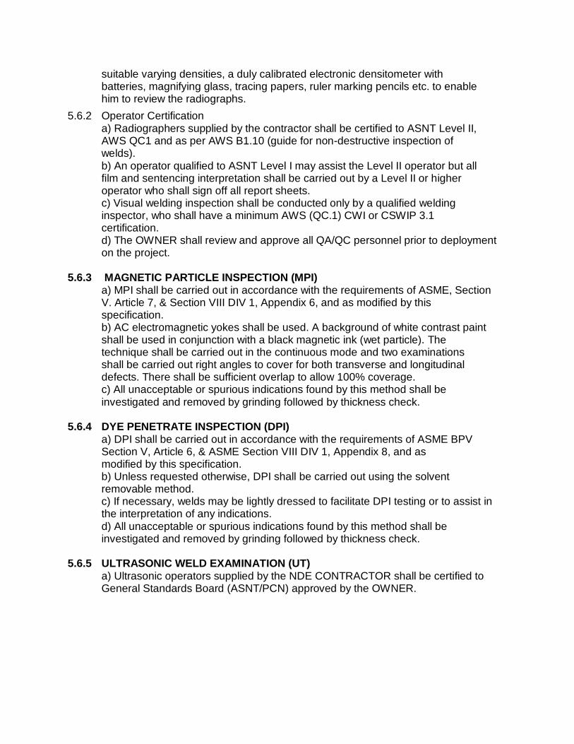
suitable varying densities, a duly calibrated electronic densitometer with batteries, magnifying glass, tracing papers, ruler marking pencils etc. to enable him to review the radiographs.
5.6.2 Operator Certification a) Radiographers supplied by the contractor shall be certified to ASNT Level II, AWS QC1 and as per AWS B1.10 (guide for non-destructive inspection of welds). b) An operator qualified to ASNT Level I may assist the Level II operator but all film and sentencing interpretation shall be carried out by a Level II or higher operator who shall sign off all report sheets. c) Visual welding inspection shall be conducted only by a qualified welding inspector, who shall have a minimum AWS (QC.1) CWI or CSWIP 3.1 certification. d) The OWNER shall review and approve all QA/QC personnel prior to deployment on the project.
5.6.3 MAGNETIC PARTICLE INSPECTION (MPI)
a) MPI shall be carried out in accordance with the requirements of ASME, Section V. Article 7, & Section VIII DIV 1, Appendix 6, and as modified by this specification. b) AC electromagnetic yokes shall be used. A background of white contrast paint shall be used in conjunction with a black magnetic ink (wet particle). The technique shall be carried out in the continuous mode and two examinations shall be carried out right angles to cover for both transverse and longitudinal defects. There shall be sufficient overlap to allow 100% coverage. c) All unacceptable or spurious indications found by this method shall be investigated and removed by grinding followed by thickness check.
5.6.4 DYE PENETRATE INSPECTION (DPI) a) DPI shall be carried out in accordance with the requirements of ASME BPV Section V, Article 6, & ASME Section VIII DIV 1, Appendix 8, and as modified by this specification. b) Unless requested otherwise, DPI shall be carried out using the solvent removable method. c) If necessary, welds may be lightly dressed to facilitate DPI testing or to assist in the interpretation of any indications. d) All unacceptable or spurious indications found by this method shall be investigated and removed by grinding followed by thickness check.
5.6.5 ULTRASONIC WELD EXAMINATION (UT) a) Ultrasonic operators supplied by the NDE CONTRACTOR shall be certified to General Standards Board (ASNT/PCN) approved by the OWNER.
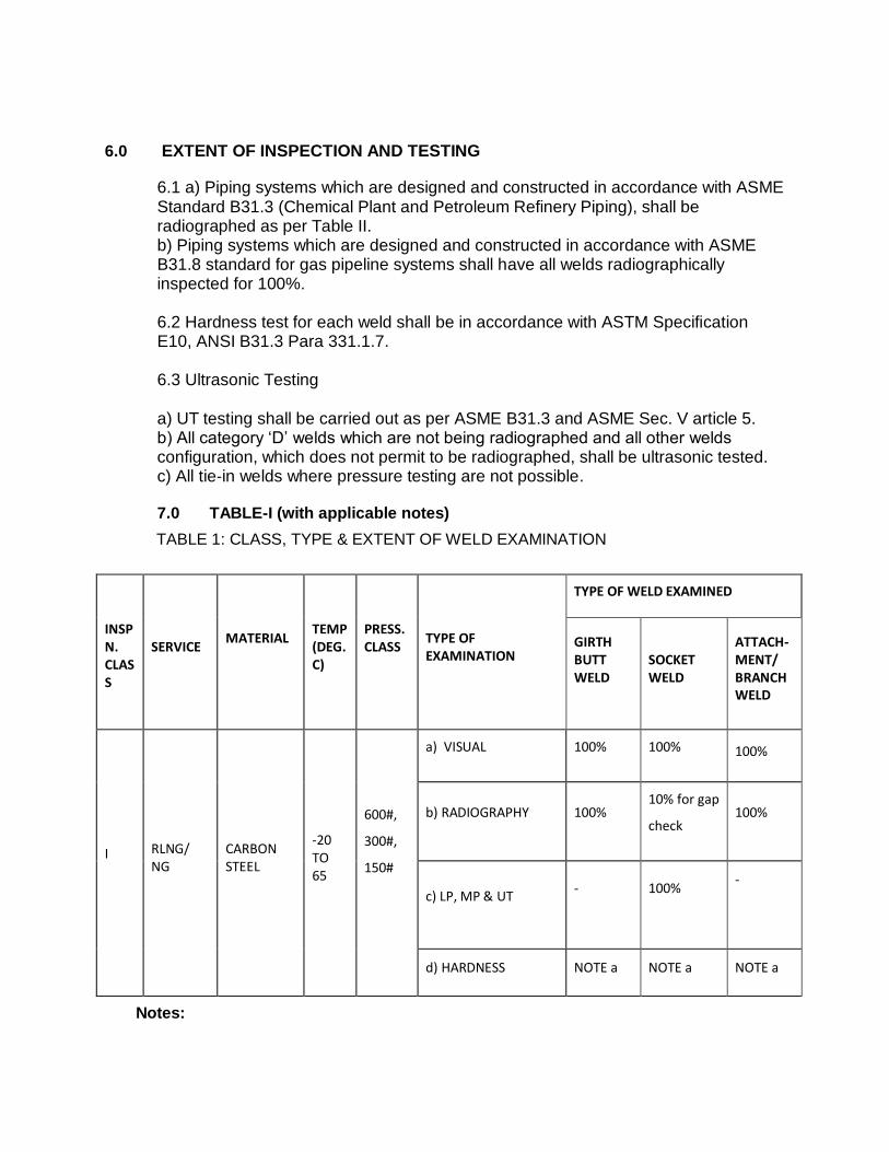
6.0 EXTENT OF INSPECTION AND TESTING
6.1 a) Piping systems which are designed and constructed in accordance with ASME Standard B31.3 (Chemical Plant and Petroleum Refinery Piping), shall be radiographed as per Table II. b) Piping systems which are designed and constructed in accordance with ASME B31.8 standard for gas pipeline systems shall have all welds radiographically inspected for 100%. 6.2 Hardness test for each weld shall be in accordance with ASTM Specification E10, ANSI B31.3 Para 331.1.7. 6.3 Ultrasonic Testing a) UT testing shall be carried out as per ASME B31.3 and ASME Sec. V article 5. b) All category ‘D’ welds which are not being radiographed and all other welds configuration, which does not permit to be radiographed, shall be ultrasonic tested. c) All tie‐in welds where pressure testing are not possible. 7.0 TABLE-I (with applicable notes)
TABLE 1: CLASS, TYPE & EXTENT OF WELD EXAMINATION
INSPN. CLASS
SERVICE MATERIAL
TEMP (DEG.C)
PRESS. CLASS
TYPE OF EXAMINATION
TYPE OF WELD EXAMINED
GIRTH BUTT WELD
SOCKET WELD
ATTACH- MENT/ BRANCH WELD
I RLNG/ NG
CARBON STEEL
-20 TO 65
600#,
300#,
150#
a) VISUAL 100% 100% 100%
b) RADIOGRAPHY 100% 10% for gap
check 100%
c) LP, MP & UT
-
100%
-
d) HARDNESS NOTE a NOTE a NOTE a
Notes:
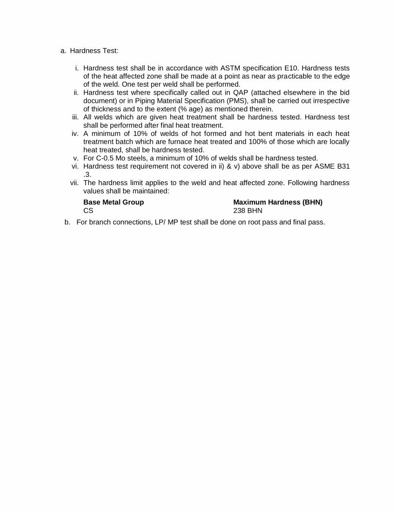
a. Hardness Test:
i. Hardness test shall be in accordance with ASTM specification E10. Hardness tests of the heat affected zone shall be made at a point as near as practicable to the edge of the weld. One test per weld shall be performed.
ii. Hardness test where specifically called out in QAP (attached elsewhere in the bid document) or in Piping Material Specification (PMS), shall be carried out irrespective of thickness and to the extent (% age) as mentioned therein.
iii. All welds which are given heat treatment shall be hardness tested. Hardness test shall be performed after final heat treatment.
iv. A minimum of 10% of welds of hot formed and hot bent materials in each heat treatment batch which are furnace heat treated and 100% of those which are locally heat treated, shall be hardness tested.
v. For C-0.5 Mo steels, a minimum of 10% of welds shall be hardness tested. vi. Hardness test requirement not covered in ii) & v) above shall be as per ASME B31
.3. vii. The hardness limit applies to the weld and heat affected zone. Following hardness
values shall be maintained:
Base Metal Group Maximum Hardness (BHN)
CS 238 BHN
b. For branch connections, LP/ MP test shall be done on root pass and final pass.
PAINTING
1.0 SCOPE
1.1 This specification defines the requirements for surface preparation, selection and
application of primers and paints on external surfaces of equipment, vessels, machinery, piping, ducts, steel structures, etc. The items listed in the heading of tables of paint systems is indicative only, however, the contractor is fully responsible for carrying out all the necessary painting, coating as per the tender requirement.
1.2 Extent of Work 1.2.1 The following surfaces and materials shall require shop, pre-erection and field painting:
a. All uninsulated C.S. & A.S. equipment like columns, vessels, drums, storage tanks(both external & internal surfaces), heat exchangers, pumps, compressors, electrical panels and motors etc.
b. All uninsulated carbon and low alloy piping, fittings and valves (including painting of
identification marks), furnace ducts and stacks. c. All items contained in a package unit as necessary. d. All structural steel work, pipe, structural steel supports, walkways, handrails,
ladders, platforms etc. e. Flare lines, external surfaces of MS chimney with or without refractory lining and
internal surfaces of MS chimney without refractory lining. f. Identification colour bands on all piping as required including insulated aluminum
clad, galvanized, SS and nonferrous piping. g. Identification lettering/numbering on all painted surfaces of equipment/piping
insulated aluminum clad, galvanized, SS and non-ferrous piping. h. Marking / identification signs on painted surfaces of equipment/piping including
hazardous service. i. Supply of all primers, paints and all other materials required for painting j. Over insulation surface of equipments and pipes wherever required. k. Painting under insulation for carbon steel, alloy steel and stainless steel as
specified. l. Painting of pre-erection/fabrication and Shop primer.
m. Repair work of damaged pre-erection/fabrication and shop primer and weld joints in the field/site before and after erection as required.
n. All CS Piping, equipments, storage tanks and internal surfaces of RCC tanks in ETP
plant.
1.2.2 The following surfaces and materials shall not require painting in general. However, if there is any specific requirement by the owner, the same shall be painted as per the relevant specifications:
a. Un insulated austenitic stainless steel. b. Plastic and/or plastic coated materials c. Non-ferrous materials like aluminum.
1.2.3 Documents 1.2.3.1 The contractor shall perform the work in accordance with the following documents
issued to him for execution of work.
a. Bill of quantities for piping, equipment, machinery and structures etc. b. Piping Line List. e. Painting specifications including special civil defence requirements.
1.2.4 Unless otherwise instructed, final painting on pre-erection/ shop primed pipes and
equipments shall be painted in the field, only after the mechanical completion, testing on systems are completed as well as after completion of steam purging wherever required.
1.2.5 Changes and deviations required for any specific job due to clients requirement or
otherwise shall be referred to Consultant/ Owner for deviation permit.
2.0 CODES & STANDARDS
Without prejudice to the specifications of the contract, the following codes and
standards shall be followed for the work covered by this contract.
IS: 5 Colors for ready mixed paints and enamels. IS: 101 Methods of test for ready mixed paints and enamels, IS: 161 Heat resistant paints. IS: 2074 Specifications for ready mixed paint, red oxide zinc chrome priming. IS: 2339 Aluminum paint for general purposes in dual container. IS: 2379 Color code for identification of pipelines. IS: 2932 Specification for enamel, synthetic, exterior (a) undercoating. (b)
Finishing.
3.0 CONDITIONS OF DELIVERY
Packaging Every recipient will be fitted with a hermetically-sealed lid with an opening that is
sufficiently large to allow the contents to be stirred: the outside and inside are protected against oxidation,
and, the lid, are marked with a strip of color identical to the contents.
4.0 COMPOSITION OF THE PAINT PRODUCTS USED
a) Quality The composition and quality of the products may not differ from batch to batch.
A batch is all of the products of a specified manufacture. If the analyses of products bring to light that the composition does not conform to the specifications of the paint manufacturer, the OWNER may refuse to use this batch of products. The paint products must comply with the following conditions
They must have the viscosity necessary for the described use and the established condition: use of the brush - paint roller (spray gun only for special cases and in the workshop)
b) Quality control - Sampling
While the works are in progress on the construction site, the OWNER may carry
out sampling on the paint being used for the purpose of checking conformity. The paint products must be made available free of charge to the laboratory or the approved supervisory body in sufficient quantities so that all the tests can be carried out on the same batch.
If analyses reveal a non-conformity in the composition of the products used, the
OWNER may refuse application of the product under consideration, halt the work and have the nonconforming product already applied removed.
Before proceeding with the work, a product data sheet with its test certificates &
batch certificate stating that products offered conform to the required specification, are to be submitted for owner/ consultant’s approval. The only Purpose of the analysis is to find out any non-conformity of the composition of the products. Their purpose is therefore not to assess the quality of the different components. The analysis concerned are not acceptance tests of the products supplied and in no way affect the obligations of the Contractor towards the OWNER.
5.0 IDENTIFICATION
Every recipient will bear the following information:
Name of the manufacturer
Date and number of manufacture
Name of the product type
Batch no
Net weight of the produced or the contents of the recipient
Date of the expiry. At the time of delivery, packaging must bear labels in conformity with the legal
stipulations in force. Leaving the site after work After completion of a job, a general clean-up shall be carried out by the Contractor to
remove all debris, materials or irregularities that his work has brought to the site so that it is left tidy.
The restoration work includes:
the removal of abrasives.
the removal of the different protective coverings.
the Contractor will make the required repairs to any damage after refitting the supports.
the removal of paint and cleaning of the stains on the floor.
6.0 SURFACE PREPARATION STANDARDS
Following standards shall be followed for surface preparations: 1 Swedish Standard Institution- SIS-05 5900-1967 2 Steel Structures Painting Council, U.S.A. (Surface Preparation Specifications
(SSPC-SP) 3 British Standards Institution (Surface Finish of Blast-cleaned for Painting) BS-
4232.
4 IS-1477-1971 (Part-1) - Code of Practice for Painting of Ferrous metals in Buildings. (Part 1, Pre-treatment)
a) The contractor shall arrange, at his own cost to keep a set of latest
edition of above standards and codes at site.
b). The paint manufacturer's instruction shall be followed as far as
practicable at all times. Particular attention shall be paid to the following:
Proper storage to avoid exposure as well as extremes of
temperature.
Surface preparation prior to painting.
Mixing and thinning.
Application of paints and the recommended limit on time
intervals between coats.
c) Any painting work (including surface preparation) on piping or equipment shall be commenced only after the system tests have been completed and clearance for taking up painting work is given by the OWNER, who may, however, at his discretion authorize in writing, the taking up of surface preparation or painting work in any specific location, even prior to completion of system test.
7.0 PREPARATION OF THE SURFACES
7.1 General Specifications The cases that occur in practice on building sites, with regard to painted surfaces,
can be broken down as follows:
Material of which the oxide content disappears by natural oxidation.
Material that has already been covered with a layer of paint in the workshop.
Material that is covered with old paint layers that show different degrees of
weathering.
Good surface preparation is the best guarantee for good anti-corrosion protection. Paintwork may never begin until the surface to be treated is dry and is independent of
the base coat and cleared of dirt, dust, rust, scale, grease, salt attack, cement powder, cement mud-scale, sand, oil, etc.
Based on the environmental conditions of coastal and saline nature, the Painting specification for station pipes defines the complete requirements like:
Surface preparation standards like NACE etc.
Sand blasting process
Color Codes for piping
Paint materials types and their DFT measurement.
Selection and application of paints on external surfaces.
The pipeline passes through the coastal and marine environment, the Table-4 of this
specification to be followed for the painting works.
The method of preparation of the surface will be implemented in accordance with the preparation methods described below:
Cleaning (bright blast-cleaning);
Mechanical cleaning;
Manual derusting.
The Contractor should have the required material at his disposal to clean the surfaces
to be coated thoroughly in accordance with the preparation methods regardless of the form or the condition of such surfaces. The cleaning devices that might be damaged during the surface preparation shall be screened off by the Contractor.
7.2 Sandblasting Before beginning cleaning by blasting, the person carrying out the work will take the
following measures:
Clear the steel surface of oil and/or grease;
Ensure that each flange collar (section where the sealing is applied) is properly
screened off against the blasting and the subsequent works;
Check that no blasting grains can act into the pipes during this process. Any
openings not sealed off must be screened off;
Where there are valves, regulators and other devices, the manufacturer's
identification plate will be dismantled so that all surfaces can be treated. The
plate will then be put back again.
Screen off all non-metal structures such as rubber where there is a filter;
With valves, operators and other devices, care should be taken to ensure that no
metal filings or paint get into the apparatus:
The OWNER reserves the right to carry out part or all of these works himself.
To prevent rust forming quickly as the result of humidity on the blasted surface, cleaning
by blasting may only be carried out when the temperature of the steel surface is at least 3°C higher than the dew-point of the ambient air.
Blasting may not be carried out if the relative degree of humidity exceeds 80%. The
choice of the type of blasting medium used depends on local circumstances such as the possible presence of gas and the material to be blasted.
The abrasive to be used must conform to the local low i.e. it may contain no carbon and less than 1% free silicon dioxide. The surface preparation must conform to the minimum standard set by SA 2½ before start of the any paintwork. The degree of cleanliness to be obtained will be inspected in accordance with the Swedish standard ISO 8501-1:2007
SA 2½: blasted very carefully. Scale, rust and foreign bodies must be removed in such a way that near white surface is achieved.
The blast-cleaning will be carried out by means of compressed air free of water and oil. After the blasting and before painting, the surface should be completely cleaned of
blasting material and so forth with a soft brush, a dry cloth or dry compressed air. 7.3 Mechanical cleaning If sandblasting is not permitted or if the metal structures are not easily accessible for
blasting or blasting for one reason or another is technically unfeasible, mechanical derusting can be used instead, by prior approval from Owner / Consultant. With mechanical cleaning by means of chipping, rotating steel brushes and sanding discs, a degree of cleanliness St. 3 should be reached.
St 3 : removal of the old paint layers of which the adhesion leaves something to be
desired and/or of which the paint layer no longer fulfils the requirements. If parts are present that are so corroded that St 3 is difficult to achieve, this should be
notified to the OWNER representative prior to the start of the works. N.B: St. 3 : means removal of every old paint layer. Retouching means local polishing with
St. 3 or Sa 3 followed by application of the desired painting system. After mechanical cleaning, the surface should be made dust-free with a cloth or a soft
brush, washed with an organic solvent and thoroughly dried off with a dry cloth (e.g. with 1.1.1.) Trichoroethane such as Solvethane, Chloromethane).
7.4 Manual Derusting Manual de-rusting with the aid of scrapers, steel brushes, sandpaper etc. shall only be
permitted in exceptional cases for local repairs. Any deviation must be requested from the OWNER/ OWNER 's Representative.
With manual derusting, a surface preparation degree St 3 must be obtained. The length
of the handles of the equipment used may not exceed 50 cm. 7.5 Preparation of a surface covered with a layer of paint in the workshop. This layer is in general applied by the manufacturer, for example, on valves, regulators
etc. Layers of this kind will be checked for their proper adhesion in accordance with
ASTM D 3359, method A (Standard Test Method for measuring adhesion by tape test). The adhesion should be at least 4A.
If the paint layer shows less adhesion or is incompatible with the rest of the system it
should be completely removed. If the paint layer is not removed, the Contractor accepts it in the state in which the coating is found and the guarantee remains in force. The adhesion does not have to be examined if system 63 has already been applied in the workshop on behalf of the OWNER.
The Contractor, who must provide for the protection on the construction site, must
therefore obtain the information regarding the treatment of the surface and the quality of the paint that was used and must, moreover, examine the adhesion of the layer on the construction site, the percentage of damage and weathering as well as the value of the preparation of the surface in the workshop together with the thickness thereof that must be supplemented if necessary.
a) Galvanized surface Galvanized surfaces, both old and new will be carefully roughened up. Every
foreign body (concrete splatters, chalk marks, grease and oil stains, etc.) will be removed. Thereafter, rub the surfaces with abundant water and, if necessary, with cleaning products.
To this end, nylon brushes will be used for every kind of dirt as well as for removing
zinc salt residue. Thereafter, the surfaces will be treated in accordance with system 21. Where the zinc layer is lacking, it will be derusted manually to a degree of cleanliness St 3, after which a primer coat will be applied in accordance with system 22.
b) Metallised surfaces treated with an impregnation layer
degrease with the desired degreasing product:
clean under high pressure or with a product prescribed by the paint supplier.
If the paint layer adheres well and is applied on a clean base, the painting system described may be continued. If the percentage of damage and weathering does not exceed 5 % per m. retouching may be considered. These partial repairs will be carried out.
If on the other hand, the percentage of damage does exceed 5 % per m or if the layer
applied in the workshop comes loose the Contractor must draw the attention of the OWNER to this and carry out the complete application system.
7.6 Preparation of surfaces covered with earlier paint layers that show different degrees of
weathering. If the surfaces do not show deep weathering limited to the spread of rust by small pitted
areas or non-penetrative rust in spots, it will very often be sufficient to clean the surfaces with abrasives or with an abrasive disc, then to rub them down with steel wool, remove the dust and wash off. If thick rust appears, in spots, scale rust and active rust
canker, this should be removed with needle hammers or stripped away directly by blasting, removing the dust and washing oft.
7.7 Preparation of concrete or cement plaster surfaces Remove unsound paint layers and loose components with scrapers, blades or rotating
steel brushes. Thoroughly clean the entire surface with water containing ammonia. Thoroughly remove moss, algae and fungal growths. Where these growths have been removed, treat the area with a fungicide in accordance with the instructions for use.
Once the entire area is completely dry, brush off the dead residue of moss, algae and
fungus with a hard brush. In the case of reinforcement steel that has been laid bare, remove as rust, dust and grease as possible and treat with a printer coat. When painting concrete surfaces, they must first be checked for cracks. Cracks larger than 0.3 mm must be repaired with an appropriate system in accordance with the type and extent of the repairs (e.g. injection with epoxy mortar). Repair damage such as cracks and bursts to concrete parts with a two-component mortar or preferably with micro-mortars. Finally check the alkalinity of the surface with the aid of litmus paper and neutralize it if necessary.
7.8 Use of solvents It is sometimes necessary to use solvents when the surfaces to be painted are streaked
with grease or oil. In this case a suitable organic solvent should be applied. The operation should be carried out with the aid of clean brushes or rags and clean solvent.
All the legal specifications in connection with solvents etc. must be adhered to. The
OWNER/OWNER's Representative will be informed in advance of any toxicity or flammability. All measures must be taken to prevent any risk of fire and to nick out any possibility of poisoning (ventilation). The Contractor will provide drip collectors to keep the environment free of pollution.
7.9 Condition of the metal after stripping The Contractor must call in a representative of the OWNER/OWNER's representative or
of the Approved supervisory Body responsible for checking the condition of the metal during stripping and informing the OWNER/OWNER's representative immediately of any damage that he might have noticed.
Deep corrosion of the plates - rivets - bolts
Faulty welding
Fittings that appear to be dangerous because of their age. 7.10 Removing coating from surface pipelines The Contractor must have the equipment necessary for the removal of asphalt from the
pipe without damaging the latter (scratching, impact, etc,). The Contractor undertakes to carry out the work in accordance with an approved procedure.
8.0 CARRYING OUT THE PAINTWORK 8.1 Conditions for carrying out paintwork Painting may not be carried out in unsuitable conditions. All preparatory work and painting may only he carried out in dry weather and at a
minimum temperature of 10C, except for special cases requested by the OWNER's Representative.
Unless otherwise stipulated in the specifications of the paint supplier, application of the
paint is forbidden if it is forecast that the temperature will fall to below 0C before the paint is dry. The temperature of-the surface to be painted must be at least 3°C higher than the dew point of the ambient air. Application of the paint is also not permitted if there is a danger that the coat of paint will not be dry before dew or condensation sets in.
The work must be stopped:
If the temperature of the surface to be painted is higher than that described by the supplier.
In rain, snow, mist or fog or when the relative humidity is higher than 80 %. Coats that have not yet dried and have been exposed to frost, mist, snow or rain and
might thereby be damaged must be removed after drying and the surfaces must be repainted at the expense of the Contractor.
Working in direct sunlight or in hot weather must be avoided, The first coat of paint must be applied maximum 3 hours after the preparation of the
surface of the relative humidity of the air is between 50% and 80%. This time span may be increased to 6 hours if the relative humidity is less than 50%. In all cases, the preparation of the surface must exhibit degree Sa 3 and at the very least the appearance of degree Sa 2 ½ at the time of painting.
The coats of paint may only be applied on carefully cleaned surfaces that must be dry
and free of grease and dust. 8.2 Special conditions Painting may be carried out when the Contractor can be sure that the instructions of the
paint supplier have been scrupulously followed with regard to the parameters in the following (non-exhaustive) list:
Ambient temperature.
Surface temperature.
Relative humidity.
Dew point.
Drying times. The Contractor must in this respect be able to produce the instructions for the paint on
the site. The OWNER/CONSULTANT will guarantee 100% supervision in this regard during the execution of the work.
In addition, the paintwork may only be carried out to a minimum ambient temperature of
5°C and/or to a maximum relative degree of humidity of 80 %. Application of the paint is also not permitted if there is a danger that the coat of paint will not be dry before dew or condensation sets in.
8.3 Paint Materials Manufacturers shall furnish the characteristics of all paints indicating the suitability for
the required service conditions. Primer and finish coats shall be of class-I quality and shall conform to the following:
Primer (P-1)
Red oxide Zinc Chromate Primer
Type and Composition Single pack, Modified phenolic alkyd medium
pigmented with red oxide and zinc chromate. Volume solids 30 - 35% DFT 25 microns/coat (min) Covering capacity 12-13 m²/Lit/coat Primer (P-2)
High build chlorinated rubber zinc phosphate primer
Type and Composition Single pack, Chlorinated rubber medium
Plasticised with unsaponifiable plasticiser pigmented with zinc phosphate
Volume solids 35- 40% DFT 50 MICRONS/COAT (MIT) Covering capacity 7-8 m²/Lit/Coat Primer (P-3)
High build zinc phosphate primer
Type and Composition Single Pack, Synthetic medium, pigmented with zinc phosphate.
Volume solids 40-45% DFT 35-50 microns/coat Covering capacity 10-12 m²/Lit/coat Heat resistance Upto 100º C (dry) Primer (P-4)
Etch Primer / Wash Primer Type and Composition Two pack Poly vinyl butyral resin medium cured with
phosphoric acid solution pigmented with zinc tetroxy chromate.
Volume solids 7-8% DFT 8-10 microns/coat Covering capacity 7-8 m²/lit/coat Primer (P-5)
Epoxy Zinc Chromate Primer Type and Composition Two pack, Polyamide cured epoxy resin medium
pigmented with zinc chromate. Volume solids 40%(min) DFT 35 microns/coat (min) Covering capacity 11-12 m2/lit/Coat Primer (P-6) Epoxy Zinc Phosphate Primer Type and Composition Two pack, Polyamide cured Epoxy resin medium
pigmented with zinc phosphate. Volume solids 40% 35 microns / coat (min) Covering capacity 11-12 m²/lit/coat Primer (P-7) Epoxy high build M10 Paint (Intermediate Coat) Type and composition Two pack Poly Polyamide cured epoxy resin
medium pigmented with micaceous iron oxide. Volume solids 7- 8%
Volume Solids 50%
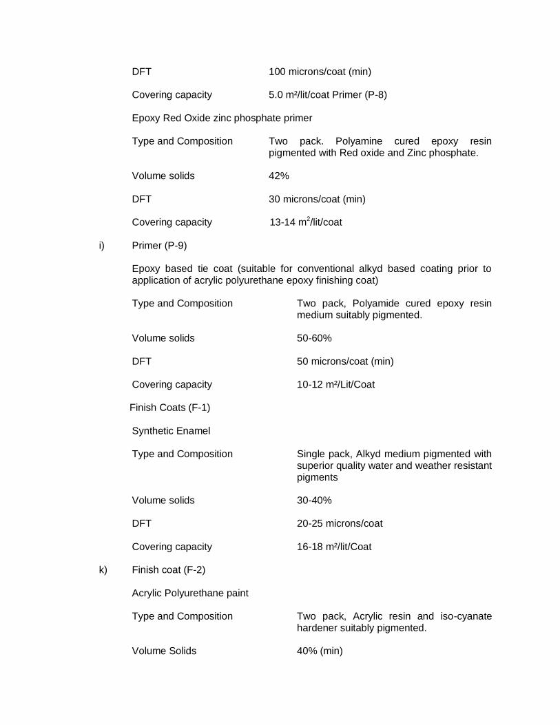
DFT 100 microns/coat (min) Covering capacity 5.0 m²/lit/coat Primer (P-8) Epoxy Red Oxide zinc phosphate primer Type and Composition Two pack. Polyamine cured epoxy resin
pigmented with Red oxide and Zinc phosphate. Volume solids 42% DFT 30 microns/coat (min) Covering capacity 13-14 m2/lit/coat i) Primer (P-9) Epoxy based tie coat (suitable for conventional alkyd based coating prior to
application of acrylic polyurethane epoxy finishing coat) Type and Composition Two pack, Polyamide cured epoxy resin
medium suitably pigmented. Volume solids 50-60% DFT 50 microns/coat (min) Covering capacity 10-12 m²/Lit/Coat
Finish Coats (F-1)
Synthetic Enamel Type and Composition Single pack, Alkyd medium pigmented with
superior quality water and weather resistant pigments
Volume solids 30-40% DFT 20-25 microns/coat Covering capacity 16-18 m²/lit/Coat k) Finish coat (F-2) Acrylic Polyurethane paint Type and Composition Two pack, Acrylic resin and iso-cyanate
hardener suitably pigmented. Volume Solids 40% (min)
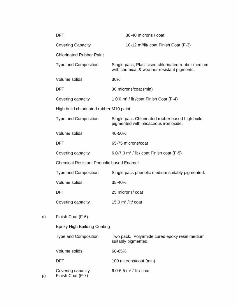
DFT 30-40 microns / coat Covering Capacity 10-12 m²/lit/ coat Finish Coat (F-3)
Chlorinated Rubber Paint Type and Composition Single pack, Plasticised chlorinated rubber medium
with chemical & weather resistant pigments. Volume solids 30% DFT 30 microns/coat (min) Covering capacity 1 0.0 m² / lit /coat Finish Coat (F-4)
High build chlorinated rubber M10 paint.
Type and Composition Single pack Chlorinated rubber based high build
pigmented with micaceous iron oxide.
Volume solids 40-50%
DFT 65-75 microns/coat
Covering capacity 6.0-7.0 m² / lit / coat Finish coat (F-5)
Chemical Resistant Phenolic based Enamel
Type and Composition Single pack phenolic medium suitably pigmented.
Volume solids 35-40%
DFT 25 microns/ coat
Covering capacity 15.0 m² /lit/ coat
o) Finish Coat (F-6)
Epoxy High Building Coating Type and Composition Two pack. Polyamide cured epoxy resin medium
suitably pigmented.
Volume solids 60-65%
DFT 100 microns/coat (min)
Covering capacity 6.0-6.5 m² / lit / coat p) Finish Coat (F-7)
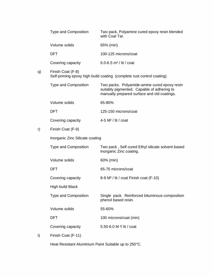
Type and Composition Two pack, Polyamine cured epoxy resin blended
with Coal Tar.
Volume solids 65% (min)
DFT 100-125 microns/coat
Covering capacity 6.0-6.5 m² / lit / coat
q) Finish Coat (F-8) Self-priming epoxy high build coating (complete rust control coating)
Type and Composition Two packs. Polyamide-amine cured epoxy resin
suitably pigmented. Capable of adhering to manually prepared surface and old coatings.
Volume solids 65-80%
DFT 125-150 microns/coat
Covering capacity 4-5 M² / lit / coat
r) Finish Coat (F-9)
Inorganic Zinc Silicate coating
Type and Composition Two pack , Self cured Ethyl silicate solvent based
Inorganic Zinc coating.
Volume solids 60% (min)
DFT 65-75 microns/coat
Covering capacity 8-9 M² / lit / coat Finish coat (F-10) High build Black
Type and Composition Single pack. Reinforced bituminous composition
phenol based resin.
Volume solids 55-60%
DFT 100 microns/coat (min)
Covering capacity 5.50-6.0 M ²/ lit / coat
t) Finish Coat (F-11)
Heat Resistant Aluminium Paint Suitable up to 250°C.
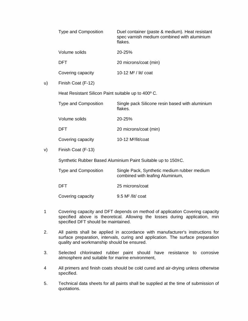
Type and Composition Duel container (paste & medium). Heat resistant spec varnish medium combined with aluminium flakes.
Volume solids 20-25%
DFT 20 microns/coat (min)
Covering capacity 10-12 M² / lit/ coat
u) Finish Coat (F-12)
Heat Resistant Silicon Paint suitable up to 400º C.
Type and Composition Single pack Silicone resin based with aluminium
flakes.
Volume solids 20-25%
DFT 20 microns/coat (min)
Covering capacity 10-12 M²/lit/coat
v) Finish Coat (F-13)
Synthetic Rubber Based Aluminium Paint Suitable up to 150C.
Type and Composition Single Pack, Synthetic medium rubber medium combined with leafing Aluminium,
DFT 25 microns/coat
Covering capacity 9.5 M² /lit/ coat
1 Covering capacity and DFT depends on method of application Covering capacity specified above is theoretical. Allowing the losses during application, min specified DFT should be maintained.
2. All paints shall be applied in accordance with manufacturer's instructions for
surface preparation, intervals, curing and application. The surface preparation quality and workmanship should be ensured.
3. Selected chlorinated rubber paint should have resistance to corrosive
atmosphere and suitable for marine environment, 4 All primers and finish coats should be cold cured and air-drying unless otherwise
specified. 5. Technical data sheets for all paints shall be supplied at the time of submission of
quotations.
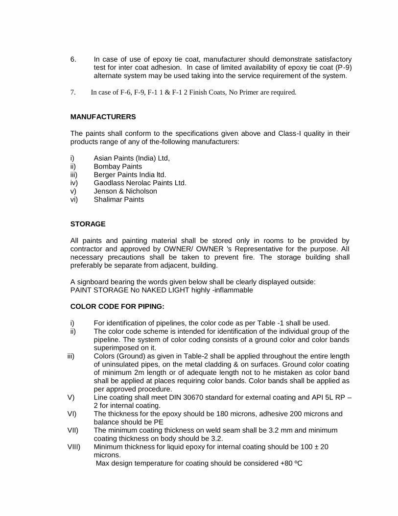
6. In case of use of epoxy tie coat, manufacturer should demonstrate satisfactory
test for inter coat adhesion. In case of limited availability of epoxy tie coat (P-9) alternate system may be used taking into the service requirement of the system.
7. In case of F-6, F-9, F-1 1 & F-1 2 Finish Coats, No Primer are required.
MANUFACTURERS The paints shall conform to the specifications given above and Class-I quality in their
products range of any of the-following manufacturers:
i) Asian Paints (India) Ltd, ii) Bombay Paints iii) Berger Paints India ltd. iv) Gaodlass Nerolac Paints Ltd. v) Jenson & Nicholson vi) Shalimar Paints
STORAGE All paints and painting material shall be stored only in rooms to be provided by
contractor and approved by OWNER/ OWNER 's Representative for the purpose. AlI necessary precautions shall be taken to prevent fire. The storage building shall preferably be separate from adjacent, building.
A signboard bearing the words given below shall be clearly displayed outside: PAINT STORAGE No NAKED LIGHT highly -inflammable COLOR CODE FOR PIPING:
i) For identification of pipelines, the color code as per Table -1 shall be used. ii) The color code scheme is intended for identification of the individual group of the
pipeline. The system of color coding consists of a ground color and color bands superimposed on it.
iii) Colors (Ground) as given in Table-2 shall be applied throughout the entire length of uninsulated pipes, on the metal cladding & on surfaces. Ground color coating of minimum 2m length or of adequate length not to he mistaken as color band shall be applied at places requiring color bands. Color bands shall be applied as per approved procedure.
V) Line coating shall meet DIN 30670 standard for external coating and API 5L RP – 2 for internal coating.
VI) The thickness for the epoxy should be 180 microns, adhesive 200 microns and balance should be PE
VII) The minimum coating thickness on weld seam shall be 3.2 mm and minimum coating thickness on body should be 3.2.
VIII) Minimum thickness for liquid epoxy for internal coating should be 100 ± 20 microns.
Max design temperature for coating should be considered +80 ºC
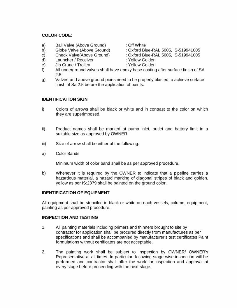
COLOR CODE:
a) Ball Valve (Above Ground) : Off White b) Globe Valve (Above Ground) : Oxford Blue-RAL 5005, IS-519941005 c) Check Valve(Above Ground) : Oxford Blue-RAL 5005, IS-519941005 d) Launcher / Receiver : Yellow Golden e) Jib Crane / Trolley : Yellow Golden f) All underground valves shall have epoxy base coating after surface finish of SA
2.5 g) Valves and above ground pipes need to be properly blasted to achieve surface
finish of Sa 2.5 before the application of paints. IDENTIFICATION SIGN
i) Colors of arrows shall be black or white and in contrast to the color on which
they are superimposed. ii) Product names shall be marked at pump inlet, outlet and battery limit in a
suitable size as approved by OWNER. iii) Size of arrow shall be either of the following:
a) Color Bands
Minimum width of color band shall be as per approved procedure.
b) Whenever it is required by the OWNER to indicate that a pipeline carries a
hazardous material, a hazard marking of diagonal stripes of black and golden, yellow as per IS:2379 shall be painted on the ground color.
IDENTIFICATION OF EQUIPMENT
All equipment shall be stenciled in black or white on each vessels, column, equipment,
painting as per approved procedure. INSPECTION AND TESTING
1. All painting materials including primers and thinners brought to site by contractor for application shall be procured directly from manufactures as per
specifications and shall be accompanied by manufacturer's test certificates Paint formulations without certificates are not acceptable.
2. The painting work shall be subject to inspection by OWNER/ OWNER's
Representative at all times. In particular, following stage wise inspection will be performed and contractor shall offer the work for inspection and approval at every stage before proceeding with the next stage.
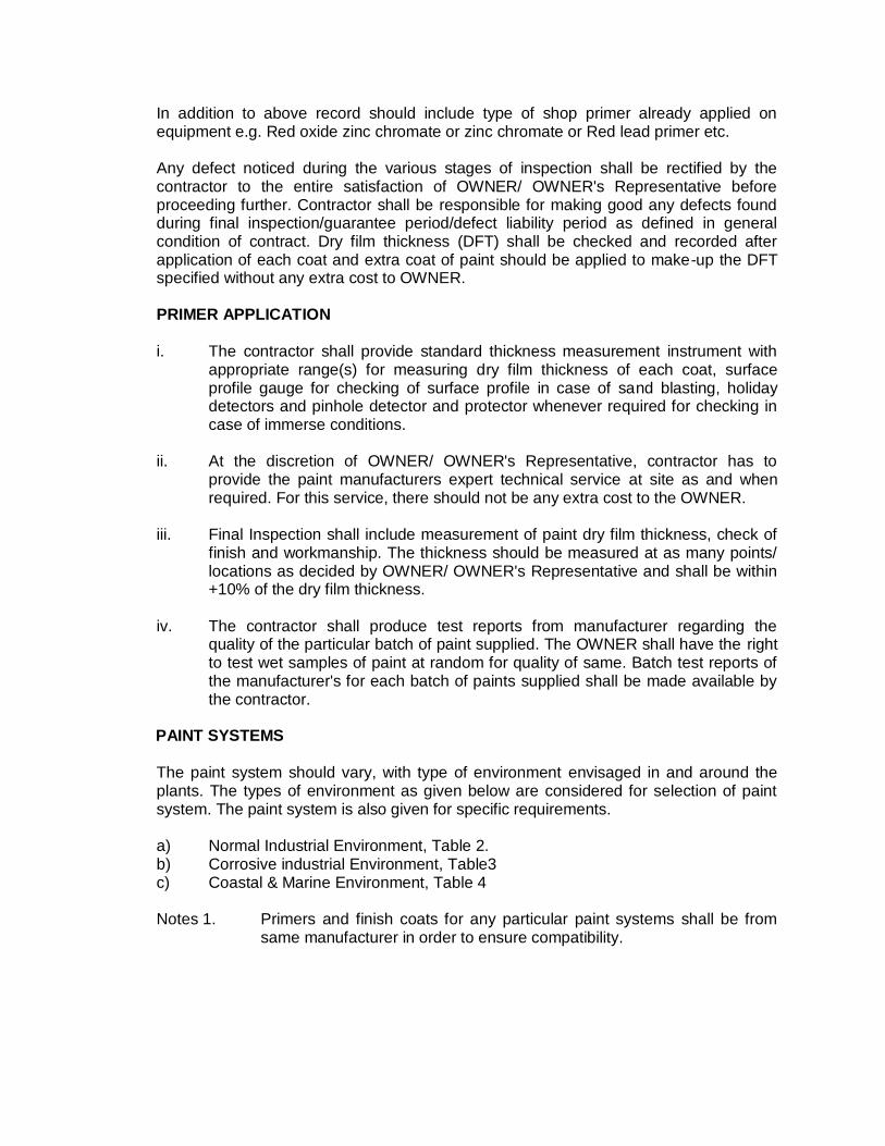
In addition to above record should include type of shop primer already applied on equipment e.g. Red oxide zinc chromate or zinc chromate or Red lead primer etc.
Any defect noticed during the various stages of inspection shall be rectified by the
contractor to the entire satisfaction of OWNER/ OWNER's Representative before proceeding further. Contractor shall be responsible for making good any defects found during final inspection/guarantee period/defect liability period as defined in general condition of contract. Dry film thickness (DFT) shall be checked and recorded after application of each coat and extra coat of paint should be applied to make-up the DFT specified without any extra cost to OWNER.
PRIMER APPLICATION i. The contractor shall provide standard thickness measurement instrument with
appropriate range(s) for measuring dry film thickness of each coat, surface profile gauge for checking of surface profile in case of sand blasting, holiday detectors and pinhole detector and protector whenever required for checking in case of immerse conditions.
ii. At the discretion of OWNER/ OWNER's Representative, contractor has to
provide the paint manufacturers expert technical service at site as and when required. For this service, there should not be any extra cost to the OWNER.
iii. Final Inspection shall include measurement of paint dry film thickness, check of
finish and workmanship. The thickness should be measured at as many points/ locations as decided by OWNER/ OWNER's Representative and shall be within +10% of the dry film thickness.
iv. The contractor shall produce test reports from manufacturer regarding the
quality of the particular batch of paint supplied. The OWNER shall have the right to test wet samples of paint at random for quality of same. Batch test reports of the manufacturer's for each batch of paints supplied shall be made available by the contractor.
PAINT SYSTEMS
The paint system should vary, with type of environment envisaged in and around the
plants. The types of environment as given below are considered for selection of paint system. The paint system is also given for specific requirements.
a) Normal Industrial Environment, Table 2. b) Corrosive industrial Environment, Table3 c) Coastal & Marine Environment, Table 4
Notes 1. Primers and finish coats for any particular paint systems shall be from
same manufacturer in order to ensure compatibility.
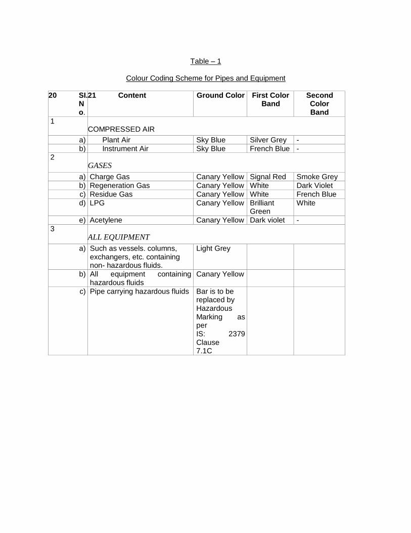
Table – 1
Colour Coding Scheme for Pipes and Equipment
20 SI. No.
21 Content Ground Color First Color Band
Second Color Band
1 COMPRESSED AIR
a) Plant Air Sky Blue Silver Grey -
b) Instrument Air Sky Blue French Blue - 2
GASES
a) Charge Gas Canary Yellow Signal Red Smoke Grey
b) Regeneration Gas Canary Yellow White Dark Violet
c) Residue Gas Canary Yellow White French Blue
d) LPG Canary Yellow Brilliant Green
White
e) Acetylene Canary Yellow Dark violet -
3 ALL EQUIPMENT
a) Such as vessels. columns, exchangers, etc. containing non- hazardous fluids.
Light Grey
b) All equipment containing hazardous fluids
Canary Yellow
c) Pipe carrying hazardous fluids Bar is to be replaced by Hazardous Marking as per IS: 2379 Clause 7.1C
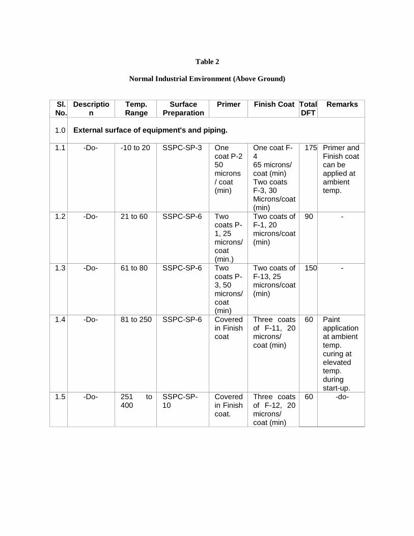
Table 2
Normal Industrial Environment (Above Ground)
Sl. No.
Description
Temp. Range
Surface Preparation
Primer Finish Coat Total DFT
Remarks
1.0 External surface of equipment's and piping.
1.1 -Do- -10 to 20 SSPC-SP-3 One coat P-2 50 microns / coat (min)
One coat F-4 65 microns/ coat (min) Two coats F-3, 30 Microns/coat (min)
175 Primer and Finish coat can be applied at ambient temp.
1.2 -Do- 21 to 60 SSPC-SP-6 Two coats P-1, 25 microns/ coat (min.)
Two coats of F-1, 20 microns/coat (min)
90 -
1.3 -Do- 61 to 80 SSPC-SP-6 Two coats P-3, 50 microns/ coat (min)
Two coats of F-13, 25 microns/coat (min)
150 -
1.4 -Do- 81 to 250 SSPC-SP-6 Covered in Finish coat
Three coats of F-11, 20 microns/ coat (min)
60 Paint application at ambient temp. curing at elevated temp. during start-up.
1.5 -Do- 251 to 400
SSPC-SP-10
Covered in Finish coat.
Three coats of F-12, 20 microns/ coat (min)
60 -do-
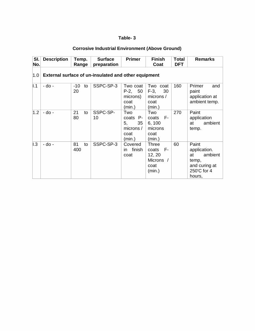
Table- 3
Corrosive Industrial Environment (Above Ground)
SI. No.
Description Temp. Range
Surface preparation
Primer Finish Coat
Total DFT
Remarks
1.0 External surface of un-insulated and other equipment
I.1 - do - -10 to 20
SSPC-SP-3 Two coat P-2, 50 microns) coat (min.)
Two coat F-3, 30 microns / coat (min.)
160 Primer and paint application at ambient temp.
1.2 - do - 21 to 80
SSPC-SP-10
Two coats P-5, 35 microns / coat (min.)
Two coats F- 6, 100 microns coat (min.)
270 Paint application at ambient temp.
I.3 - do - 81 to 400
SSPC-SP-3 Covered in finish coat
Three coats F- 12, 20 Microns / coat (min.)
60 Paint application. at ambient temp, and curing at 250'C for 4 hours,
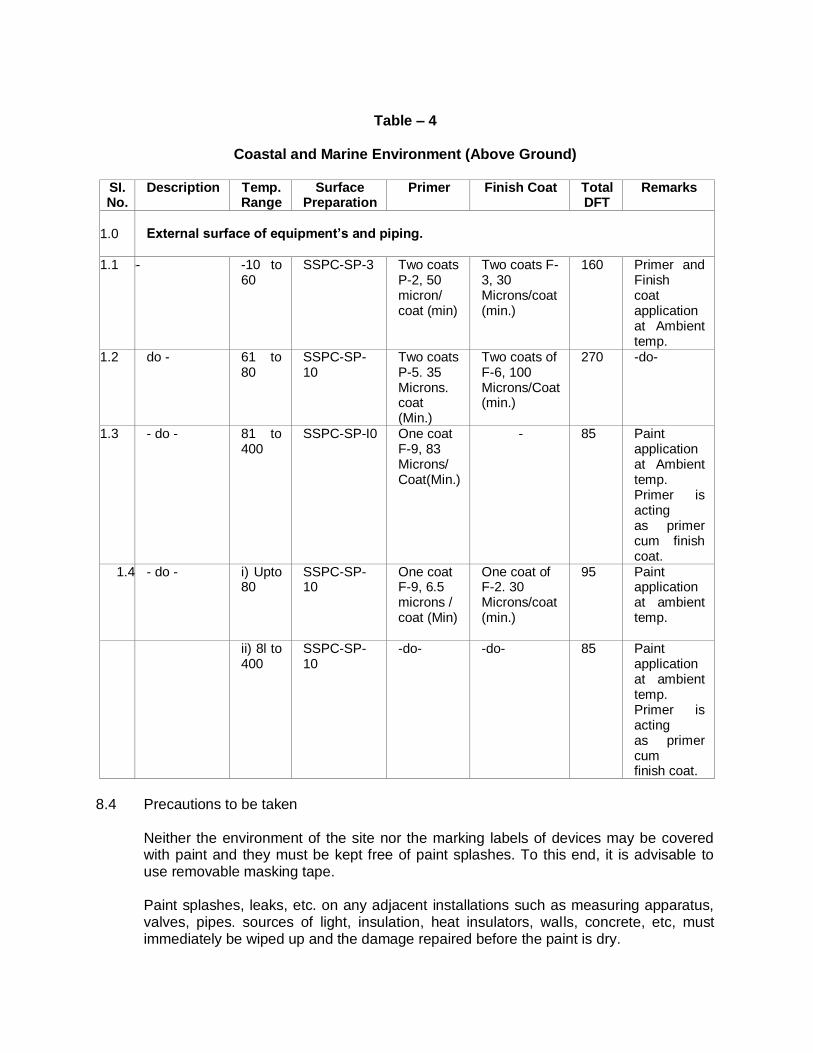
Table – 4
Coastal and Marine Environment (Above Ground)
SI. No.
Description Temp. Range
Surface Preparation
Primer Finish Coat Total DFT
Remarks
1.0 External surface of equipment’s and piping.
1.1 -do- -10 to 60
SSPC-SP-3 Two coats P-2, 50 micron/ coat (min)
Two coats F- 3, 30 Microns/coat (min.)
160 Primer and Finish coat application at Ambient temp.
1.2 do - 61 to 80
SSPC-SP-10
Two coats P-5. 35 Microns. coat (Min.)
Two coats of F-6, 100 Microns/Coat (min.)
270 -do-
1.3 - do - 81 to 400
SSPC-SP-I0 One coat F-9, 83 Microns/ Coat(Min.)
- 85 Paint application at Ambient temp. Primer is acting as primer cum finish coat.
1.4 - do - i) Upto 80
SSPC-SP- 10
One coat F-9, 6.5 microns / coat (Min)
One coat of F-2. 30 Microns/coat (min.)
95 Paint application at ambient temp.
ii) 8l to 400
SSPC-SP- 10
-do- -do- 85 Paint application at ambient temp. Primer is acting as primer cum finish coat.
8.4 Precautions to be taken Neither the environment of the site nor the marking labels of devices may be covered
with paint and they must be kept free of paint splashes. To this end, it is advisable to use removable masking tape.
Paint splashes, leaks, etc. on any adjacent installations such as measuring apparatus,
valves, pipes. sources of light, insulation, heat insulators, walls, concrete, etc, must immediately be wiped up and the damage repaired before the paint is dry.
Otherwise, the OWNER will be obliged to have the cleaning carried out at the expense
of the Contractor. The paint recipient will only be opened at the time of use (unless otherwise specified by the manufacturer).
The product will be mixed in the recipient with the aid of suitable tools and thus
homogenized. 8.5 Method of application Normally, three methods of application will be used on the construction site for the paint
products, i.e., with a brush, with a roller or with a spray gun.
The brush method makes it possible to obtain good penetration of the paint over irregularities in the metal.
Only this method will be used for application of the base coats, for retouching and for protrusions, welded areas, riveted joints or bolted joints:
The roller method may be used on large flat surfaces for the intermediate and topcoats.
The spray gun method must be used in accordance with the instructions of the manufacturer and carried out by qualified personnel.
The Contractor must guarantee that all safety measures have been taken for such work.
The spray gun method may only he used on site for places that arc difficult to reach with the brush. In this case, a request must be made to the OWNER/ OWNER's Representative for a deviation.
All paintwork will be carried out with good brushes or rollers that are suitable for the type
of paint being used and for the form of the material to be painted and fitted with short handles. The maximum length of the brush and roller handles will be 50 cm; longer handles may only be used for places that are absolutely inaccessible. The maximum width of a brush will be 13 cm.
8.6 Application of the coating Application of the paint will be carried out in accordance with best practice in order to
obtain a homogeneous and continuous layer. The OWNER or the Approved Supervisory body demands that painting of a layer will only be started after acceptance by them of the surface preparation or of the previous layer of paint.
The layers of paint must have a uniform thickness. They must he spread in such a way
that all concave parts are dried out and that the surface is completely covered and has a glossy appearance without leaving brush marks and without exhibiting bubbles, foam, wrinkles, drips, craters, skins or gums that arise from weathered paint,
Each layer must have the color stipulated in the tables of the present specifications,
which clearly differs from the previous layer, taking account of the Color of the top layer,
all of which for the purpose of being able to identify the number of coats and their order of sequence. If the color of the coats is not mentioned in the tables the color difference in consecutive coats must, if possible, be at least 100 RAL. The color of the top layer is given in the table.
The coating power should be such that the underlying layer is not visible. Only 1 layer
per day may be applied, unless otherwise specified by the OWNER or the Approved Supervisory Body.
The drying times prescribed by the paint manufacturer must be strictly observed in
relation to the environmental conditions before proceeding with the application of the next layer.
The dry coating thickness indicated in the description of the paint systems are minimum
thickness. In this connection, the Contractor is obliged to contact the paint manufacturer and conform to his guidelines. The Contractor must respect the thickness specified by the supplier.
1.9.7 Transporting treated items In the case of works being carried out in a workshop, the metal structures will be
surrounded by ventilated contraction film that prevents damage during transportation. This film may only be applied after complete polymerization of the paint.
1.10 GROUND-LEVEL TRANSITION POINT 1.11 Polyester protection system The Contractor will provide system 02 over the entire length of the pipes above ground
and below ground and up to a height of 20 cm and a depth of 40 cm. perpendicular to the ground level mark. In each case, he must ensure that the jointing below the asphalt is in good condition and assures' faultless adhesion. He will apply the following products over the entire surface area, prepared in accordance with is Sa 3:
1) The primer of system 01.
2) Reinforced polyester ± 20 cm above the ground level marker and ± 5 cm on the
asphalt cleaned beforehand (application of reinforced polyester is carried out in accordance with the work method prescribed by the manufacturer). Moreover, in the case of PE, in contrast to asphalt, he will apply a polygon primer to PE immediately before applying the reinforced polyester.
3) He will then apply the other coats of system 01a to the surface section and thus
cover the reinforced polyester with about 5 cm. 4) For new constructions, the polygon primer will be applied to PE and then
subsequently processed as described under point 2. 1.11.1 USE OF SCAFFOLDING
Mounting, maintenance and dismantling of scaffolding for carrying out adaptation and/or paintwork to surface gas pipes or gas transport installations in use;
The Contractor will specify the cost of scaffolding in the price list.
The supplementary rental price for delays attributable to the Contractor will be charged to him:
In his price quotation the Contractor should present the OWNER with diagrams of the scaffolding that he intends to install for carrying out the works of the OWNER.
1.12 QUALITY CONTROLS AND GUARANTEE 1.12.1 The Contractor is responsible for checking the weather conditions to ascertain whether
the paintwork can be carried out within the technical specifications. The Contractor should have the required calibrated monitoring apparatus for this
purpose on site (with calibration certificates). The personnel who will have to use this apparatus should have the training for this purpose.
The OWNER or his representative and possibly the approved supervisory body
indicated by the OWNER will maintain supervision during the works and inspect the works with random checks. A daily report will be drawn up in relation to the department that maintains supervision of these works.
The supplementary inspection and the supervision by the OWNER or the approved
supervisory body do not diminish in any way the liability of the Contractor. The proper execution of the work and the materials used may be checked at any time.
1.12.2 Reference Surfaces At the start of the works. the OWNER or the approved supervisory body will indicate a
few surfaces that the Contractor will prepare and cover in accordance with the recognized method of operation under the inspection and to the satisfaction of all parties ; the OWNER or his representative, the approved supervisory body. the contractor and possibly the paint manufacturer. These reference surfaces will serve as a point of comparison for the good adhesion of the paint on the installations as a whole. The parties will together work out a system for the identification of these surfaces in order to be able to monitor the conditions of the coatings over time. If the paintwork on a section of the installations is in a worse condition than the reference surfaces, the Contractor may be obliged to treat these parts again.
1.12.3 Measures to be taken in the event of a dispute If on delivery of the works no agreement can be reached between the Contractor and
the OWNER regarding the conformity of the works to the requirements of these specifications, an Approved Supervisory Body will he Called in. The Approved Supervisory Body will then carry out inspections' on site whereby the following assessment criteria wilt be used:
The Swedish standards ISO 8501-1:2007 SS 05.5900 concerning the degree of cleanliness of the areas derusted by blasting, by machine or by hand.
The wet film thickness of the paint will be measured in accordance with ISO 2808 or ASTM DI 212;
The dry layer thickness of the film will be measured electronically, will complete statistical information. in accordance will, ISO 2808 or ASTM D 1186.
The thickness of each layer will he measured in accordance with ISO 2808. ASTM 4138 or DIN 50986.
Adhesion tests will be carried out in accordance with ISO 2409. ASTM 3359 or DIN 53151.
Traction tests will he carried out in conformity with ISO 4624 or ASTM D 4541.
The rugosity will be measured electronically in accordance with DIN 4768;
The non-porosity will be measured with a test tension depending on the type of coating, the layer thickness and after consultation with the Paint manufacturer.
Any defects in the paint film may be inspected visually by means of a magnifying glass or microscope. If necessary a photographic report may be drawn up in accordance with ASTM Standard D 4121-82,
The final judgement of the Approved Supervisory Body is irrevocable and binding for the
Contractor and the OWNER. In the event of non-conformity of the works with the criteria of these specifications, all costs arising from the inspection by the Approved Supervisory Body shall be borne by the Contractor.
1.12.4 Guarantee a) General Principles The Contractor declares that he is aware of:
The maximum operating temperature of the surfaces to be covered.
The maximum permitted degree of humidity of the bearing surface.
The properties of the environment to which the surfaces to be covered are: subject.
b) Summary of the Guarantee. The contractor fully guarantees the following without reservation:
The observance of all stipulations of the specifications for paintwork regarding,

among other things:
o The preparation of the surfaces. o The thickness of each layer. o The total thickness of the covering.
The uniformity of the materials used.
The repair of all defects before delivery of the works.
The Contractor will carry out the requested repair work as promptly as possible.
WELDING OF STATION PIPING
1.0 SCOPE
This specification covers general requirements for welding of all types of station piping works. The specification covers the scope of work, basis of work, standards, specifications and normal practice to be followed by the contractor during execution of station piping works.
No supplier, vendor, manufacturer or fabricator shall subcontract the welding fabrication
of any item without written approval from the OWNER. The CONTRACTOR shall be fully responsible for works completed by him.
The welded pipe joints shall include the following and shall not relieve the contractor of his responsibilities and guarantee. a) All pipe joints, longitudinal butt welds, circumferential butt welds and socket welds.
b) Attachments of forging, flanges and other supports to pipes.
c) Welded manifold headers and other sub assemblies.
d) Welded branch connections with or without reinforcing pads.
e) Joints in welded / fabricated piping components.
f) The attachments of smaller connection for vents drain drips and other instrument tapings.
2.0 CODES AND STANDARDS
The related standards referred to herein and mentioned below shall be of the latest editions prior to the date of the purchaser's enquiry:
a) Indian codes and standards (OISD & PNGRB) augmented with the following: 1. AWS (American Welding Society).
a. A2.4 (Symbols for Welding and Non destructive Testing).
b. A3.0 (Standard Welding Terms and their Definitions).
c. A5.1 (Specification for Mild Steel Covered Arc Welding Electrodes).
d. A 5.17(Specification for Bare Carbon Steel Covered Electrodes).
e. A 5.18 (Specification for Carbon Steel Filler Metals for Gas Shielded Arc Welding).
f. A 5.20 (Specification for Mild Steel Electrodes for Flux Cored Arc Welding Electrodes).
2. Boilers and Pressure Vessels Act and Regulations. 3. ASME B 31.3 Chemical Plant and Petroleum Refinery and Process Piping.
4. ASME Sec. VIII Div. 1 - Pressure Vessels. 5. ASME Sec. IX – Welding and Brazing Specifications. 6. ASME B31.8 - Gas Transmission and Distribution Systems. 7. ASME Sec V - Non-destructive examination. 8. API Std 1104 – Standard for Welding Pipelines and Related Facilities.
9. AWS D 1.1 – Structural Welding code steel 10. PNGRB NOTIFICATION: Technical Standards and specifications including safety
standards for city or local natural gas distribution Schedule-1 network
In case of conflict in the requirements of this specification and / or any of the above codes or standards, the requirement that is more stringent shall apply. All welding procedures used by fabricators and CONTRACTORS shall have been established and qualified in accordance with the appropriate sections of one or more of the codes and standards listed above, and approved by the OWNER.
3.0 WELDING PROCEDURES 3.1 General
The CONTRACTOR shall submit welding procedures for review to the OWNER/ Owner’s Representative. The CONTRACTOR shall have a separate welding procedure for each method of welding he intends to employ during construction. A Procedure Qualification Record (PQR) shall be conducted and recorded for each WPS. The PQR shall be witnessed by the OWNER/ OWNER’s representative, and shall be supported with destructive testing lab report from the testing laboratory. All testing shall be performed and certified by OWNER approved testing laboratory, agency or equivalent. The written procedure must include the following details:
a. The scope of work performed under the procedures.
b. The base metals and applicable specifications.
c. The welding process.
d. Type, size, classification and composition of filler metals. (The specific brand name(s) of
the flux-wire shall become an essential variable of the procedure qualification)
e. Type of current and voltage range Amperage
f. Width of electrode weave or oscillation
g. Joint preparation and cleaning procedures.
h. Tack welding procedures. Method of marking the location of tack welds to facilitate post
weld inspection shall also be included
i. Electrode polarity.
j. Applicable welding positions.
k. Preheat and inter pass temperatures. (Control method)
l. Welding travel speed.
m. Root preparation prior to welding from second side, (where applicable).
n. Removal methods for weld defects and stray arc strikes.
o. Inter pass-cleaning method.
p. Repair welding.
q. Post welding heat treatments (if required).
r. Shielding gas, and flow rates
s. Type of (GTAW) electrode, size and tip angle.
t. Welders qualified and deployed in production welds shall always bear an identity card in the manner so approved by OWNER/OWNER’s representative.
3.2 Consumables
The CONTRACTOR shall supply all the Owner/ Owner’s Representative approved
welding consumables necessary for the execution of the job such as electrodes, filler wires, argon etc. The cost of all such consumables shall be deemed to be inclusive in the rates of welding.
The welding electrodes and filler wires supplied by the contractor shall confirm to this
specification and standard codes and shall be of the make approved by the OWNER/ OWNER’s representative. The contractor shall submit all test certificates to the Engineer in Charge for review and approval.
The contractor shall submit batch test certificates from the electrodes manufacturers,
giving details of physical and chemical tests carried out by them, for each batch of the electrodes to be used.
The contractor shall conduct Electrode Qualification Tests (EQT) and record the parameters for each batch. The EQT shall be witnessed and the test reports shall be reviewed by the Owner/ OWNER’s representative. No electrode shall be used without successful EQT of it’s batch.
The electrodes, filler wires and flux used shall be free from rust, oil, grease, earth and
other foreign matter, which affect the quality of the welding. All coated metal arc-welding electrodes shall comply with the latest edition of AWS
specification A 5.5 and A5.1 type unless approved otherwise by the OWNER. All welding consumables, including fluxes shall be supplied in sealed containers and
stored in a dry location at a minimum temperature of 68°F/ 20˚C and a maximum relative humidity of 60%. Low-hydrogen electrodes, after removal from factory sealed containers, shall be stored at a minimum temperature of 150°F/66˚C or as per manufacturer recommendations and suitably dried using a portable oven prior to every use.
The welding filler metals shall have a chemical composition as near as possible to the
parent metals to be welded. The finished weld as deposited, or after post weld heat treatment (PWHT) when required, shall be at least equal to or greater than the parent metal in terms of unit strength, ductility, and other physical properties and in resistance to corrosion, hydrogen attack, or other operating environment factors as required. Permission to change filler metals to those other than the ones qualified in accordance with this specification must be obtained in writing, from the OWNER/ Owner’s Representative.
Electrode and rod diameters shall conform to the parameters of the weld procedure
specification. The CONTRACTOR shall provide adequate drying ovens and take proper precautions in
the storage and handling of low-hydrogen electrodes. Electrodes and filler rods shall be protected from mechanical damage or deterioration.
All unidentified damaged or deteriorated electrodes or filler wires shall be removed from the working area and rejected. Any low hydrogen type SMAW electrodes not contained in heated quivers shall be removed from the site. Electrodes shall not be exposed to wet or high humid conditions.
Care of welding consumables is the responsibility of the CONTRACTOR however, the
following are minimum requirements: Low-hydrogen SMAW electrodes shall be kept in commercial electrode ovens after the
factory container has been opened. The electrode holding oven temperature shall be maintained between 175°F (79°C) and 250°F (121°C). Any low-hydrogen SMAW electrodes that have been exposed for more than 4 hours prior to restocking into the holding oven or any SMAW low-hydrogen electrodes that have become wet or have damaged coatings shall not be used and shall be immediately removed from site.
Other (non-low-hydrogen) SMAW electrodes shall be kept in a dry and dust-free
enclosure after opening of the factory container. These non-low-hydrogen electrodes shall be held at a temperature below 150°F (66°C).
Bare wire and bare filler rod (GTAW) shall be stored in a dry and free from dust, grease
etc. 3.3 Welding Process
Welding of various materials under this specification shall be carried out using one or
more welding process as given below with the approval of the ENGINEER IN CHARGE.
- Shielded Metal Arc Welding Process (SMAW) - Gas Tungsten Arc welding process (GTAW)
The CONTRACTOR shall have a separate welding procedure for each method of
welding he intends to employ. Automatic and semiautomatic welding processes shall be employed only with the
express approval of the ENGINEER IN CHARGE. The welding procedure shall be adopted and consumables used shall be specifically approved.
A procedure qualification record (PQR) shall be included for each WPS. The PQT shall
be witnessed by the OWNER/ OWNER’s Representative or shall be supported with the lab report from the testing laboratory, if so previously agreed to by the OWNER.
A combination of different welding process could be employed for a particular joint only
after duly qualifying the welding procedure to be adopted and obtaining the approval of ENGINEER IN CHARGE.
All testing shall be performed and certified by OWNER approved testing laboratory, agency or equivalent. The minimum acceptable written procedure shall detail information on the following parameters.
1. The scope of work performed under the procedures. 2. The base metals and applicable specifications. 3. The welding process. 4. Type, size, classification and composition of filler metals. (The specific brand name(s)
of the flux-wire shall become an essential variable of the procedure qualification) 5. Type of current and voltage range As per range 6. Width of electrode weave or oscillation 7. Joint preparation and cleaning procedures. 8. Tack welding procedures. Method of marking the location of tack welds to facilitate
post weld inspection shall also be included 9. Electrode polarity. 10. Applicable welding positions. 11. Preheat and inter pass temperatures. (Control method) 12. Welding travel speed. 13. Root preparation prior to welding from second side, (where applicable). 14. Removal methods for weld defects and stray arc strikes. 15. Inter pass-cleaning method. 16. Repair welding. 17. Post welding heat treatments (if required). 18. Shielding gas, and flow rates 19. Type of (GTAW) electrode, size and tip angle.
20. Welders qualified and deployed in production welds shall always bear an identity card in the manner so approved by OWNER/OWNER’s representative.
The CONTRACTOR shall only employ welders who have a valid welding certificate for
the procedures being used. The CONTRACTOR shall have all welders tested in accordance with the applicable
code or standard. Testing shall be at the Contractor's expense including test pieces. Irrespective of pre qualification all welders proposed to be deployed in the work shall be tested and qualified afresh.
No welder shall be allowed to make any weld for which he is not qualified. Welding with larger-size electrodes for specific applications may be allowed only if each welder
qualifies with the largest-size electrode to be used in production. This option is strictly at the
OWNER discretion. OWNER shall specify the details of the welder qualification tests.
For carbon steel, filler wire combinations shall be chosen such that the deposited
hardness of the cap pass shall not exceed 240 BHN. For low-temperature materials and other materials heat input shall be minimized and comply with the WIPS parameters.
The CONTRACTOR may propose alternate process in addition to those listed. Any
proposed process shall require written OWNER approval and qualification prior to implement CONTRACTOR and OWNER shall agree on tests, results, and other criteria before OWNER approval is granted.
All butt welds in pipe smaller than 60.3 mm O/D ("NPS 2" inch) Schedule 40 shall be
made by GTAW, Root pass by gas metal arc is acceptable for pipe larger than 60.3 mm O/D (NP (2'') inch).
Permanently installed backing rings shall not be used, All butt welds in pressure equipment shall have the same chemical and mechanical
properties as the parent metal. All welding procedures must be qualified for Charpy V impact testing when the Code
requirements indicate that the parent material requires impact testing. When impact tests are required, tests shall be taken from the weld metal, fusion line, 2mm from fusion line, and 5mm from fusion line.
The electrodes shall be purchased from the list of approved manufacturer's and the
same shall be supplied with proper certificates and batch certificates.
Extreme care shall be taken to ensure that electrode separation by classification is maintained in the CONTRACTOR's inventory. All storage bins and ovens for welding consumables shall be clearly labeled. In addition, all GTAW bare rod filler metals shall be tagged with the AWS designation of the filler metal. Any welding consumable that cannot be readily identified shall not be used for welding.
All pressure containing welds shall be of a minimum of two passes with overlap of starts and stops. This shall include socket welds and seal welds of threaded connections.
Weld stops and starts shall be staggered so that adjacent weld passes do not contain
stops/ starts within 25mm (1 inch) of each other. The width of weave during production welding shall be within the acceptable limit of the
OWNER approved and qualified welding procedure, qualification certificates, and production welding operating sheets. As a norm this will be limited to a maximum of 3 times the core diameter of SMAW electrodes, whichever is less.
Each weld pass layer shall be completed in one full cycle/ circumference before
proceeding with the next. Blocking out or segmental welding is not permitted. All tools and equipment used in the welding operations shall be in first class operating
condition and shall be of sufficient capacity to ensure welds of the specified quality are achieved throughout the work. It shall be the right of the OWNER to request at any times the re-calibration of gauges and meters. etc. to ensure compliance with welding procedure-operating sheets/ WPS.
3.4 Joint Preparation
The surface of the pipe at the weld area shall be free from dust, grease, scale, paint, grit
or any other foreign material, which may adversely affect the final weld quality. Bevels shall be 37½° and all field cuts shall be normal to the axis , of the pipe, Miter
welds are prohibited. All pipes shall be beveled for welding with an approved mechanical beveling machine. Damage to bevels, which could possibly affect the quality of the weld, shall be repaired
prior to welding. If repair cannot be done, the pipe shall be cut and the pipe end re-beveled. Lamination check by UT method shall be done prior to welding of gas cutting end pipe.
Where welding pipe both to a flange or another pipe or component, there must be a
band of at least 25 mm (1 inch) wide around the internal / external joint weld preparation that is ground to bright metal, and is free of all foreign matter,
To assure proper spacing and alignment in accordance with the applicable Code, an
approved lineup clamp shall be used. All welds shall conform to the straightness and alignment specified herein. Correction of
improperly fitted parts shall be accomplished by disassembly and refitting. Reworking by hammering or flame straightening shall not be permitted.
The ends of piping components to be joined shall be aligned as accurately as is
practicable within existing commercial tolerance on diameters, wall thickness, and out of roundness. Maximum bore mismatch shall not exceed 1/16” inch (1.6 mm), Alignment shall be preserved during welding.
When joints of unequal thickness are joined, the joint preparation shall be as per ASME B 31.8.
Maximum bore mismatch shall not exceed 0.8mm (1/32 inch), Where ends are to be
Joined and the internal misalignment due to difference in wall thickness, etc. exceeds 1.6 min (1/16 inch), the wall extending internally shall be internally trimmed. Internal machining shall be performed so that the inside diameters of the components coincide.
When cutting pipe to length, it should be cut by mechanical means. if practical. Ends that
are to be connected to flanges, either in the shop or in the field, must be cut true and square.
3.5 Preheating
Preheat for pressure piping and furnace tubs shall be in accordance with ASME B31.3
and B31.8. All pipe joints having a wall thickness greater than 9.5 mm (0.375") shall he preheated to
100°C prior to welding when the ambient temperature is less than 10°C (50 °F). Preheating shall he carried out with an approved torch system or with electrical induction
coils which will provide uniform heating. The preheating area shall be at least 200 mm (8") wide centered about the weld and
shall extend around the entire circumference of the pipe. Preheat temperatures shall be checked with temperature sensitive crayons or by other
approved methods. If a joint requires preheating, the same temperature requirements shall be maintained for
each succeeding pass, 3.6. Welding Details
3.6.1 All pressure welding shall be performed in accordance with approved and qualified welding procedures as required per code.
3.6.2 Each weld shall be uniform in width and size throughout its full length. 3.6.3 Each layer or welding shall be smooth and free of slag cracks, pinholes, undercuts
(Internal and external), porosity and excessive bead shall be completely fused to the adjacent weld beads and base metal.
3.6.4 The cover pass shall be free of coarse ripples, irregular surface, non-uniform pattern,
high crown, deep ridges or valleys undercut, arc strikes, porosity, undercut, slag, or shatter.
3.6.5 Butt welds shall be slightly convex, of uniform height, and have full penetration, unless
otherwise approved. 3.6.6 For piping, limitations on weld reinforcement shall apply to the internal surfaces as well
as to' the external. 3.6.7 Fillet welds shall be of a specified size with full throat and the legs of uniform length. 3.6.8 Arcs shall only be struck in the weld groove. A controlled arc must be maintained while
welding. Should an arc strike occur, it shall be removed by grinding and the area shall be etched (10% Nital) to confirm heat affected area removal, and MT examined to ensure absence of any surface cracking.
3.6.9 After each pass the layer of weld metal must be cleaned to remove all slag, scale dirt
etc. wire brushes, grinder, or chipping hammer shall be used as needed to prepare proper surface for each succeeding weld pass.
3.6.10 Repair, chipping or grinding of welds shall be done in such a manner as not to gouge,
groove or reduce the base metal thickness. 3.6.11 No welding shall be done if the temperature of the base metal is below 50°F. Nor shall
there be any welding done if there is moisture, grease, or any foreign material on the joint to be welded.
3.6.12 A qualified welder shall make tack welds. Cracked lack welds shall be completely ground
out and NDE by MT/PT prior to re-weld. 3.6.13 The CONTRACTORS shall make no substitution of materials or modifications to details
without the prior written approval of the OWNER. 3.6.14 Welders and welding operators shall not be qualified on production welds. 3.6.15 The CONTRACTOR shall ensure that welders and welding operators are only employed
on those parts of the work for which they are qualified. 3.6.16 Each welder and welding operator shall possess an appropriate temperature-measuring
device. All supervisors shall possess a copy of the approved welding procedures. 3.6.17 Alternatively, welding procedures may he clearly display at each welding location.
Welders shall be familiar with the requirements of the appropriate approved welding procedures. Any welder found not complying with the approved welding procedures during production welding shall be removed from the work and the non-conforming weld(s) may be completely rejected, at the discretion of the OWNER.
3.6.18 No welding should be undertaken without approved WPS. 3.6.19 The OWNER will not provide any WPS for the CONTRACTOR. 3.7 Welding Techniques
3.7.1 General
a) All welding shall be performed in accordance with an approved and qualified welding
procedure.
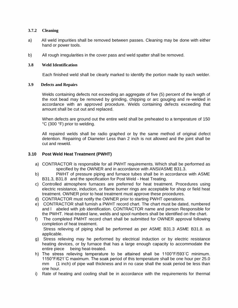
3.7.2 Cleaning
a) All weld impurities shall be removed between passes. Cleaning may be done with either
hand or power tools. b) All rough irregularities in the cover pass and weld spatter shall be removed. 3.8 Weld Identification
Each finished weld shall be clearly marked to identify the portion made by each welder.
3.9 Defects and Repairs
Welds containing defects not exceeding an aggregate of five (5) percent of the length of the root bead may be removed by grinding, chipping or arc gouging and re-welded in accordance with an approved procedure. Welds containing defects exceeding that amount shall be cut out and replaced.
When defects are ground out the entire weld shall be preheated to a temperature of 150
°C (300 °F) prior to welding. All repaired welds shall be radio graphed or by the same method of original defect
detention. Repairing of Diameter Less than 2 inch is not allowed and the joint shall be cut and reweld.
3.10 Post Weld Heat Treatment (PWHT)
a) CONTRACTOR is responsible for all PWHT requirements. Which shall be performed as specified by the OWNER and in accordance with ANSI/ASME B31.3.
b) PWHT of pressure piping and furnace tubes shall be in accordance with ASME B31.3, B31.8 and the specification for Post Weld - Heat Treating.
c) Controlled atmosphere furnaces are preferred for heat treatment. Procedures using electric resistance, induction, or flame burner rings are acceptable for shop or field heat treatment. OWNER prior to heat treatment must approve these procedures.
d) CONTRACTOR must notify the OWNER prior to starting PWHT operations.
e) CONTRACTOR shall furnish a PWHT record chart. The chart must be dated, numbered and l abeled with job identification. CONTRACTOR name and person Responsible for the PWHT. Heat-treated lane, welds and spool numbers shall be identified on the chart.
f) The completed PM/HT record chart shall be submitted for OWNER approval following completion of heat treatment.
Stress relieving of piping shall be performed as per ASME B31.3 ASME B31.8. as applicable.
g) Stress relieving may he performed by electrical induction or by electric resistance heating devices, or by furnace that has a large enough capacity to accommodate the entire piece being heat-treated.
h) The stress relieving temperature to be attained shall be 1100°F/593˚C minimum. 1150°F/621˚C maximum. The soak period of this temperature shall be one hour per 25.0 mm (1 inch) of pipe wall thickness and in no case shall the soak period be less than one hour.
i) Rate of heating and cooling shall be in accordance with the requirements for thermal
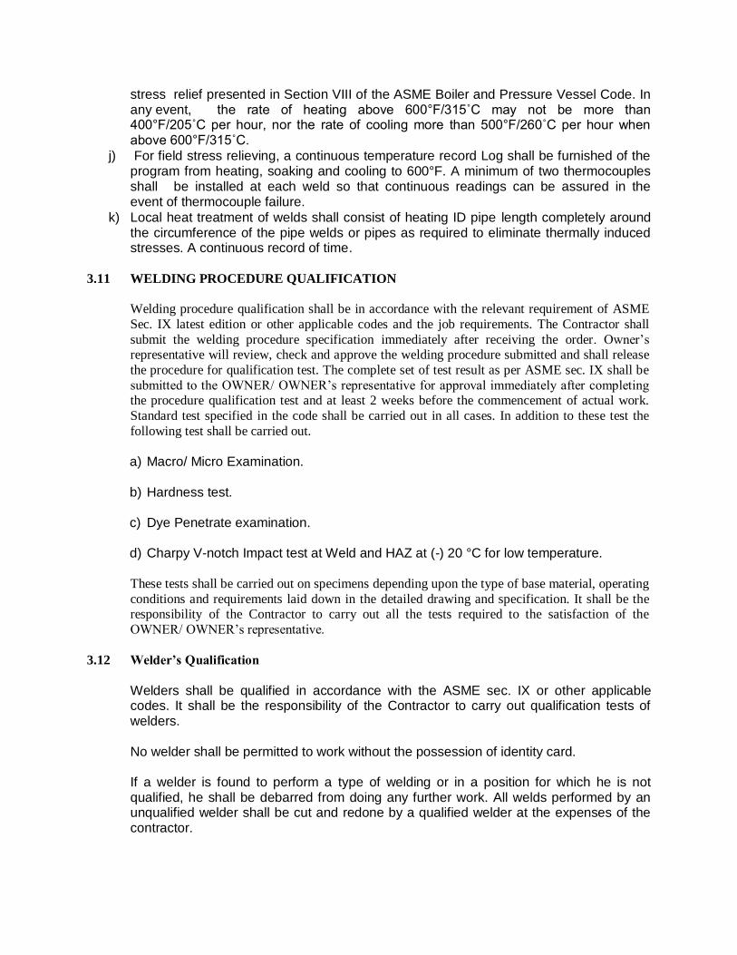
stress relief presented in Section VIII of the ASME Boiler and Pressure Vessel Code. In any event, the rate of heating above 600°F/315˚C may not be more than 400°F/205˚C per hour, nor the rate of cooling more than 500°F/260˚C per hour when above 600°F/315˚C.
j) For field stress relieving, a continuous temperature record Log shall be furnished of the program from heating, soaking and cooling to 600°F. A minimum of two thermocouples shall be installed at each weld so that continuous readings can be assured in the event of thermocouple failure.
k) Local heat treatment of welds shall consist of heating ID pipe length completely around the circumference of the pipe welds or pipes as required to eliminate thermally induced stresses. A continuous record of time.
3.11 WELDING PROCEDURE QUALIFICATION Welding procedure qualification shall be in accordance with the relevant requirement of ASME
Sec. IX latest edition or other applicable codes and the job requirements. The Contractor shall
submit the welding procedure specification immediately after receiving the order. Owner’s representative will review, check and approve the welding procedure submitted and shall release
the procedure for qualification test. The complete set of test result as per ASME sec. IX shall be
submitted to the OWNER/ OWNER’s representative for approval immediately after completing the procedure qualification test and at least 2 weeks before the commencement of actual work.
Standard test specified in the code shall be carried out in all cases. In addition to these test the
following test shall be carried out.
a) Macro/ Micro Examination.
b) Hardness test.
c) Dye Penetrate examination.
d) Charpy V-notch Impact test at Weld and HAZ at (-) 20 °C for low temperature.
These tests shall be carried out on specimens depending upon the type of base material, operating
conditions and requirements laid down in the detailed drawing and specification. It shall be the responsibility of the Contractor to carry out all the tests required to the satisfaction of the
OWNER/ OWNER’s representative.
3.12 Welder’s Qualification
Welders shall be qualified in accordance with the ASME sec. IX or other applicable codes. It shall be the responsibility of the Contractor to carry out qualification tests of welders.
No welder shall be permitted to work without the possession of identity card. If a welder is found to perform a type of welding or in a position for which he is not
qualified, he shall be debarred from doing any further work. All welds performed by an unqualified welder shall be cut and redone by a qualified welder at the expenses of the contractor.
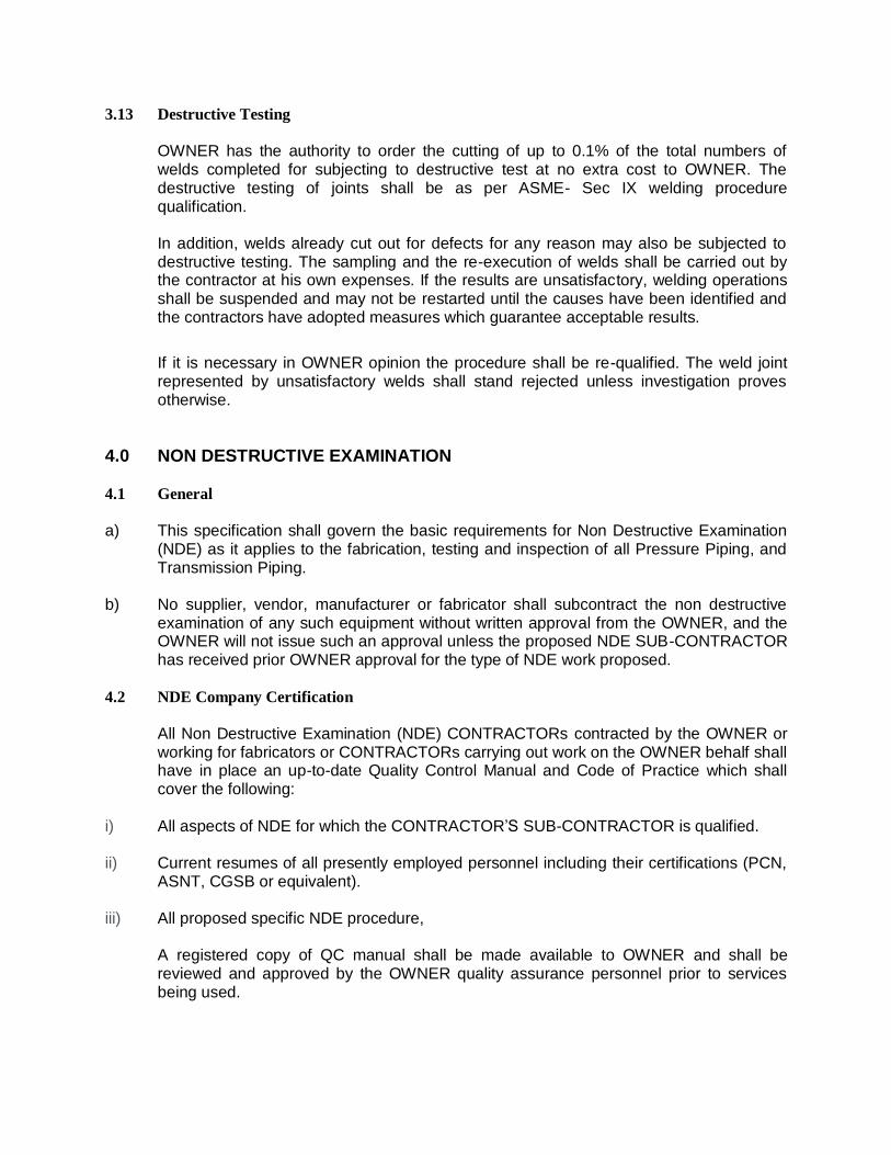
3.13 Destructive Testing
OWNER has the authority to order the cutting of up to 0.1% of the total numbers of
welds completed for subjecting to destructive test at no extra cost to OWNER. The destructive testing of joints shall be as per ASME- Sec IX welding procedure qualification.
In addition, welds already cut out for defects for any reason may also be subjected to
destructive testing. The sampling and the re-execution of welds shall be carried out by the contractor at his own expenses. If the results are unsatisfactory, welding operations shall be suspended and may not be restarted until the causes have been identified and the contractors have adopted measures which guarantee acceptable results.
If it is necessary in OWNER opinion the procedure shall be re-qualified. The weld joint
represented by unsatisfactory welds shall stand rejected unless investigation proves otherwise.
4.0 NON DESTRUCTIVE EXAMINATION 4.1 General
a) This specification shall govern the basic requirements for Non Destructive Examination
(NDE) as it applies to the fabrication, testing and inspection of all Pressure Piping, and Transmission Piping.
b) No supplier, vendor, manufacturer or fabricator shall subcontract the non destructive
examination of any such equipment without written approval from the OWNER, and the OWNER will not issue such an approval unless the proposed NDE SUB-CONTRACTOR has received prior OWNER approval for the type of NDE work proposed.
4.2 NDE Company Certification All Non Destructive Examination (NDE) CONTRACTORs contracted by the OWNER or
working for fabricators or CONTRACTORs carrying out work on the OWNER behalf shall have in place an up-to-date Quality Control Manual and Code of Practice which shall cover the following:
i) All aspects of NDE for which the CONTRACTOR’S SUB-CONTRACTOR is qualified.
ii) Current resumes of all presently employed personnel including their certifications (PCN,
ASNT, CGSB or equivalent). iii) All proposed specific NDE procedure, A registered copy of QC manual shall be made available to OWNER and shall be
reviewed and approved by the OWNER quality assurance personnel prior to services being used.
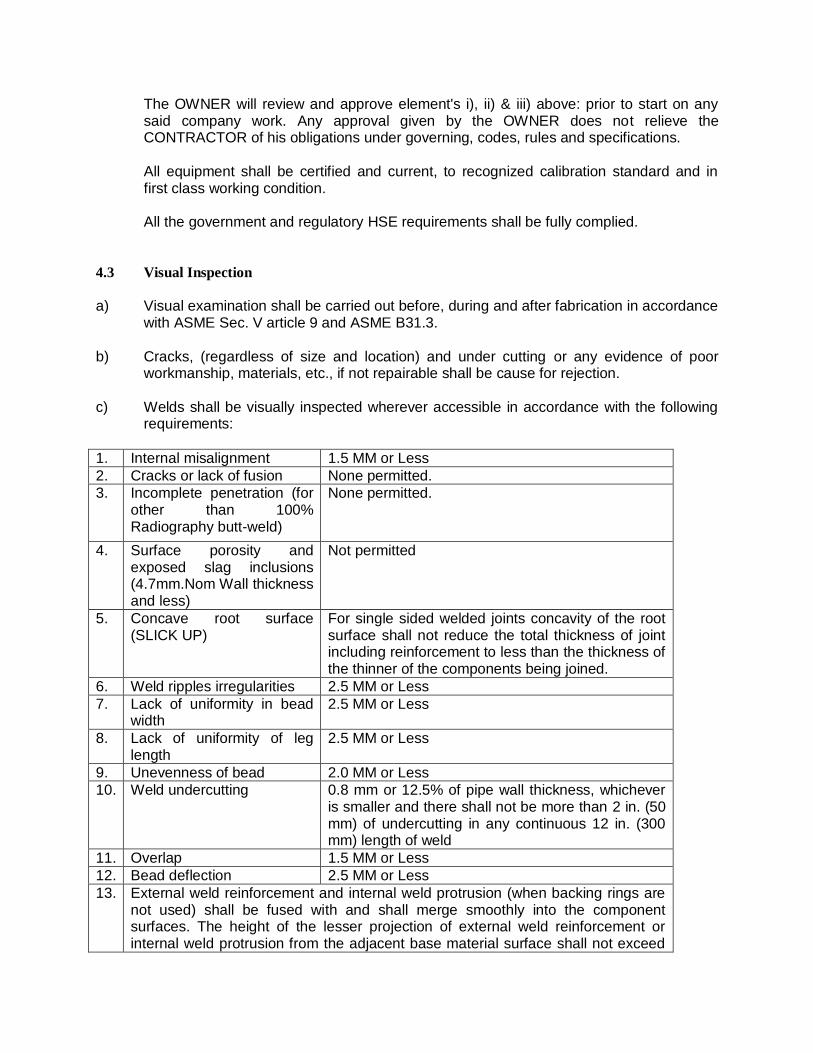
The OWNER will review and approve element's i), ii) & iii) above: prior to start on any said company work. Any approval given by the OWNER does not relieve the CONTRACTOR of his obligations under governing, codes, rules and specifications.
All equipment shall be certified and current, to recognized calibration standard and in
first class working condition. All the government and regulatory HSE requirements shall be fully complied.
4.3 Visual Inspection
a) Visual examination shall be carried out before, during and after fabrication in accordance
with ASME Sec. V article 9 and ASME B31.3.
b) Cracks, (regardless of size and location) and under cutting or any evidence of poor workmanship, materials, etc., if not repairable shall be cause for rejection.
c) Welds shall be visually inspected wherever accessible in accordance with the following requirements:
1. Internal misalignment 1.5 MM or Less
2. Cracks or lack of fusion None permitted.
3. Incomplete penetration (for other than 100% Radiography butt-weld)
None permitted.
4. Surface porosity and exposed slag inclusions (4.7mm.Nom Wall thickness and less)
Not permitted
5. Concave root surface (SLICK UP)
For single sided welded joints concavity of the root surface shall not reduce the total thickness of joint including reinforcement to less than the thickness of the thinner of the components being joined.
6. Weld ripples irregularities 2.5 MM or Less
7. Lack of uniformity in bead width
2.5 MM or Less
8. Lack of uniformity of leg length
2.5 MM or Less
9. Unevenness of bead 2.0 MM or Less
10. Weld undercutting 0.8 mm or 12.5% of pipe wall thickness, whichever is smaller and there shall not be more than 2 in. (50 mm) of undercutting in any continuous 12 in. (300 mm) length of weld
11. Overlap 1.5 MM or Less
12. Bead deflection 2.5 MM or Less
13. External weld reinforcement and internal weld protrusion (when backing rings are not used) shall be fused with and shall merge smoothly into the component surfaces. The height of the lesser projection of external weld reinforcement or internal weld protrusion from the adjacent base material surface shall not exceed
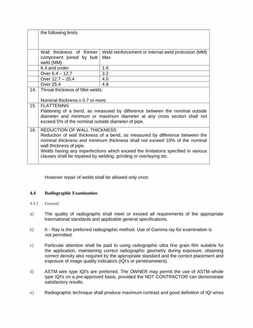
the following limits
Wall thickness of thinner component joined by butt weld (MM)
Weld reinforcement or internal weld protrusion (MM) Max
6.4 and under 1.6
Over 6.4 – 12.7 3.2
Over 12.7 – 25.4 4.0
Over 25.4 4.8
14. Throat thickness of fillet welds: Nominal thickness x 0.7 or more.
15. FLATTENING Flattening of a bend, as measured by difference between the nominal outside diameter and minimum or maximum diameter at any cross section shall not exceed 5% of the nominal outside diameter of pipe.
16. REDUCTION OF WALL THICKNESS Reduction of wall thickness of a bend, as measured by difference between the nominal thickness and minimum thickness shall not exceed 10% of the nominal wall thickness of pipe. Welds having any imperfections which exceed the limitations specified in various clauses shall be repaired by welding, grinding or overlaying etc.
However repair of welds shall be allowed only once. 4.4 Radiographic Examination
4.4.1 General
a) The quality of radiographs shall meet or exceed all requirements of the appropriate
International standards and applicable general specifications. b) X - Ray is the preferred radiographic method. Use of Gamma ray for examination is not permitted. c) Particular attention shall be paid to using radiographic ultra fine grain film suitable for
the application, maintaining correct radiographic geometry during exposure, obtaining correct density also required by the appropriate standard and the correct placement and exposure of image quality indicators (IQI's or penetrameters).
d) ASTM wire type IQI's are preferred. The OWNER may permit the use of ASTM whole
type IQI's on a pre-approved basis, provided the NDT CONTRACTOR can demonstrate satisfactory results.
e) Radiographic technique shall produce maximum contrast and good definition of IQI wires
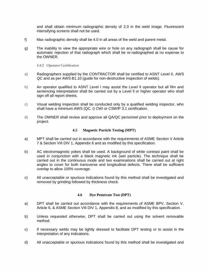
and shall obtain minimum radiographic density of 2.0 in the weld image. Fluorescent intensifying screens shall not be used.
f) Max radiographic density shall be 4.0 in all areas of the weld and parent metal. g) The inability to view the appropriate wire or hole on any radiograph shall be cause for
automatic rejection of that radiograph which shall be re-radiographed at no expense to the OWNER.
4.4.2 Operator Certification
a) Radiographers supplied by the CONTRACTOR shall be certified to ASNT Level II, AWS
QC and as per AWS B1.10 (guide for non-destructive inspection of welds).
b) An operator qualified to ASNT Level I may assist the Level II operator but all film and sentencing interpretation shall be carried out by a Level ll or higher operator who shall sign off all report sheets.
c) Visual welding inspection shall be conducted only by a qualified welding inspector, who shall have a minimum AWS (QC. I) CWI or CSWIP 3.1 certification.
d) The OWNER shall review and approve all QA/QC personnel prior to deployment on the project.
4.5 Magnetic Particle Testing (MPT)
a) MPT shall be carried out in accordance with the requirements of ASME Section V Article
7 & Section VIII DIV 1, Appendix 6 and as modified by this specification.
b) AC electromagnetic yokes shall be used. A background of white contrast paint shall be used in conjunction with a black magnetic ink (wet particle). The technique shall be carried out in the continuous mode and two examinations shall be carried out at right angles to cover for both transverse and longitudinal defects. There shall be sufficient overlap to allow 100% coverage.
c) All unacceptable or spurious indications found by this method shall be investigated and removed by grinding followed by thickness check.
4.6 Dye Penetrate Test (DPT)
a) DPT shall be carried out accordance with the requirements of ASME BPV, Section V,
Article 6, & ASME Section VIII DIV 1, Appendix 8, and as modified by this specification.
b) Unless requested otherwise, DPT shall be carried out using the solvent removable method.
c) If necessary welds may be lightly dressed to facilitate DPT testing or to assist in the interpretation of any indications.
d) All unacceptable or spurious indications found by this method shall be investigated and
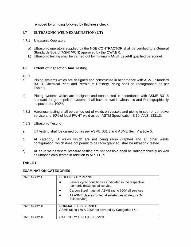
removed by grinding followed by thickness check.
4.7 ULTRASONIC WELD EXAMINATION (UT) 4.7.1 Ultrasonic Operators
a) Ultrasonic operators supplied by the NDE CONTRACTOR shall be certified to a General Standards Board (ASNT/PCN) approved by the OWNER.
b) Ultrasonic testing shall be carried out by minimum ANST Level-II qualified personnel. 4.8 Extent of Inspection And Testing 4.8.1 a) Piping systems which are designed and constructed in accordance with ASME Standard
B31.3, Chemical Plant and Petroleum Refinery Piping shall be radiographed as per Table II.
b) Piping systems which are designed and constructed in accordance with ASME B31.8
standard for gas pipeline systems shall have all welds Ultrasonic and Radiographically inspected for 100%,
4.8.2 Hardness testing shall be carried out of welds on vessels and piping in sour or corrosive
service and 10% of local PWHT weld as per ASTM Specification E 10, ANSI 1331.3. 4.8.3 Ultrasonic Testing a) UT testing shall be carried out as per ASME B31.3 and ASME Sec. V article 5. b) All category 'D' welds which are not being radio graphed and all other welds
configuration, which does not permit to be radio graphed, shall be ultrasonic tested. c) All tie-in welds where pressure testing are not possible shall be radiographically as well
as ultrasonically tested in addition to MPT/ DPT. TABLE-I EXAMINATION CATEGORIES
CATEGORY I HIGHER DUTY PIPING
Severe cyclic conditions as indicated in the respective isometric drawings, all service.
Carbon Steel material, ASME rating 600# all services
All ASME classes for lethal substances.(Category `M' fluid service)
CATEGORY II NORMAL FLUID SERVICE ASME rating 150 & 300# not covered by Categories I & III
CATEGORY III CATEGORY 1) FLUID SERVICE
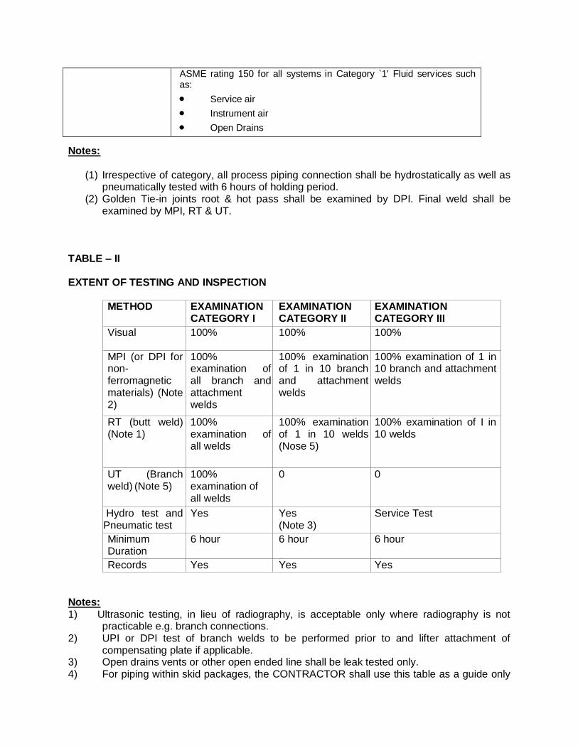
Notes:
(1) Irrespective of category, all process piping connection shall be hydrostatically as well as
pneumatically tested with 6 hours of holding period. (2) Golden Tie-in joints root & hot pass shall be examined by DPI. Final weld shall be
examined by MPI, RT & UT. TABLE – II EXTENT OF TESTING AND INSPECTION
METHOD EXAMINATION
CATEGORY I EXAMINATION CATEGORY II
EXAMINATION CATEGORY III
Visual 100% 100% 100%
MPI (or DPI for non-ferromagnetic materials) (Note 2)
100% examination of all branch and attachment welds
100% examination of 1 in 10 branch and attachment welds
100% examination of 1 in 10 branch and attachment welds
RT (butt weld) (Note 1)
100% examination of all welds
100% examination of 1 in 10 welds (Nose 5)
100% examination of I in 10 welds
UT (Branch weld) (Note 5)
100% examination of all welds
0 0
Hydro test and Pneumatic test
Yes Yes (Note 3)
Service Test
Minimum Duration
6 hour 6 hour 6 hour
Records Yes Yes Yes
Notes:
1) Ultrasonic testing, in lieu of radiography, is acceptable only where radiography is not practicable e.g. branch connections.
2) UPI or DPI test of branch welds to be performed prior to and lifter attachment of compensating plate if applicable.
3) Open drains vents or other open ended line shall be leak tested only. 4) For piping within skid packages, the CONTRACTOR shall use this table as a guide only
ASME rating 150 for all systems in Category `1' Fluid services such as:
Service air
Instrument air
Open Drains
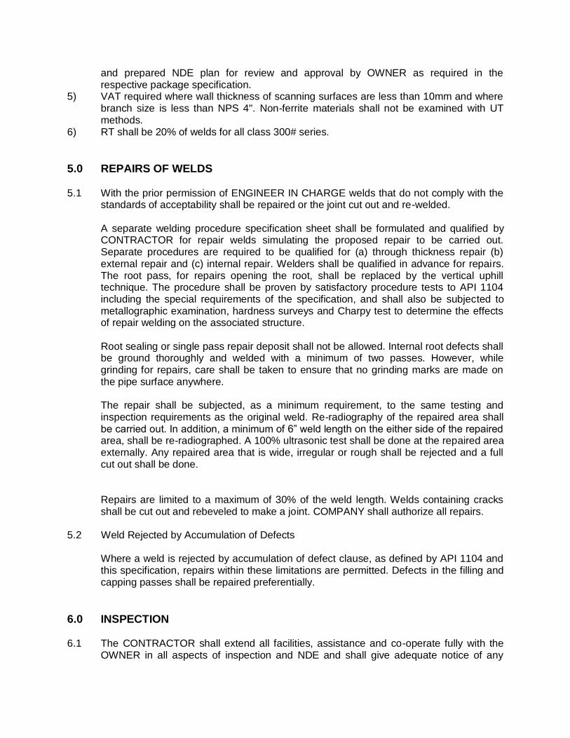
and prepared NDE plan for review and approval by OWNER as required in the respective package specification.
5) VAT required where wall thickness of scanning surfaces are less than 10mm and where branch size is less than NPS 4". Non-ferrite materials shall not be examined with UT methods.
6) RT shall be 20% of welds for all class 300# series.
5.0 REPAIRS OF WELDS
5.1 With the prior permission of ENGINEER IN CHARGE welds that do not comply with the standards of acceptability shall be repaired or the joint cut out and re-welded.
A separate welding procedure specification sheet shall be formulated and qualified by
CONTRACTOR for repair welds simulating the proposed repair to be carried out. Separate procedures are required to be qualified for (a) through thickness repair (b) external repair and (c) internal repair. Welders shall be qualified in advance for repairs. The root pass, for repairs opening the root, shall be replaced by the vertical uphill technique. The procedure shall be proven by satisfactory procedure tests to API 1104 including the special requirements of the specification, and shall also be subjected to metallographic examination, hardness surveys and Charpy test to determine the effects of repair welding on the associated structure.
Root sealing or single pass repair deposit shall not be allowed. Internal root defects shall
be ground thoroughly and welded with a minimum of two passes. However, while grinding for repairs, care shall be taken to ensure that no grinding marks are made on the pipe surface anywhere.
The repair shall be subjected, as a minimum requirement, to the same testing and
inspection requirements as the original weld. Re-radiography of the repaired area shall be carried out. In addition, a minimum of 6” weld length on the either side of the repaired area, shall be re-radiographed. A 100% ultrasonic test shall be done at the repaired area externally. Any repaired area that is wide, irregular or rough shall be rejected and a full cut out shall be done.
Repairs are limited to a maximum of 30% of the weld length. Welds containing cracks
shall be cut out and rebeveled to make a joint. COMPANY shall authorize all repairs. 5.2 Weld Rejected by Accumulation of Defects Where a weld is rejected by accumulation of defect clause, as defined by API 1104 and
this specification, repairs within these limitations are permitted. Defects in the filling and capping passes shall be repaired preferentially.
6.0 INSPECTION
6.1 The CONTRACTOR shall extend all facilities, assistance and co-operate fully with the OWNER in all aspects of inspection and NDE and shall give adequate notice of any
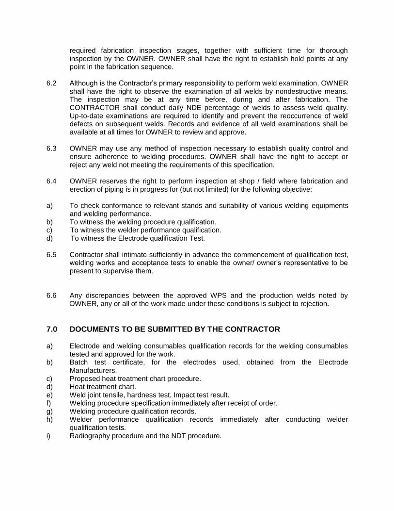
required fabrication inspection stages, together with sufficient time for thorough inspection by the OWNER. OWNER shall have the right to establish hold points at any point in the fabrication sequence.
6.2 Although is the Contractor’s primary responsibility to perform weld examination, OWNER
shall have the right to observe the examination of all welds by nondestructive means. The inspection may be at any time before, during and after fabrication. The CONTRACTOR shall conduct daily NDE percentage of welds to assess weld quality. Up-to-date examinations are required to identify and prevent the reoccurrence of weld defects on subsequent welds. Records and evidence of all weld examinations shall be available at all times for OWNER to review and approve.
6.3 OWNER may use any method of inspection necessary to establish quality control and
ensure adherence to welding procedures. OWNER shall have the right to accept or reject any weld not meeting the requirements of this specification.
6.4 OWNER reserves the right to perform inspection at shop / field where fabrication and
erection of piping is in progress for (but not limited) for the following objective: a) To check conformance to relevant stands and suitability of various welding equipments
and welding performance. b) To witness the welding procedure qualification. c) To witness the welder performance qualification. d) To witness the Electrode qualification Test. 6.5 Contractor shall intimate sufficiently in advance the commencement of qualification test,
welding works and acceptance tests to enable the owner/ owner’s representative to be present to supervise them.
6.6 Any discrepancies between the approved WPS and the production welds noted by
OWNER, any or all of the work made under these conditions is subject to rejection.
7.0 DOCUMENTS TO BE SUBMITTED BY THE CONTRACTOR a) Electrode and welding consumables qualification records for the welding consumables
tested and approved for the work. b) Batch test certificate, for the electrodes used, obtained from the Electrode
Manufacturers. c) Proposed heat treatment chart procedure. d) Heat treatment chart. e) Weld joint tensile, hardness test, Impact test result. f) Welding procedure specification immediately after receipt of order. g) Welding procedure qualification records. h) Welder performance qualification records immediately after conducting welder
qualification tests. i) Radiography procedure and the NDT procedure.
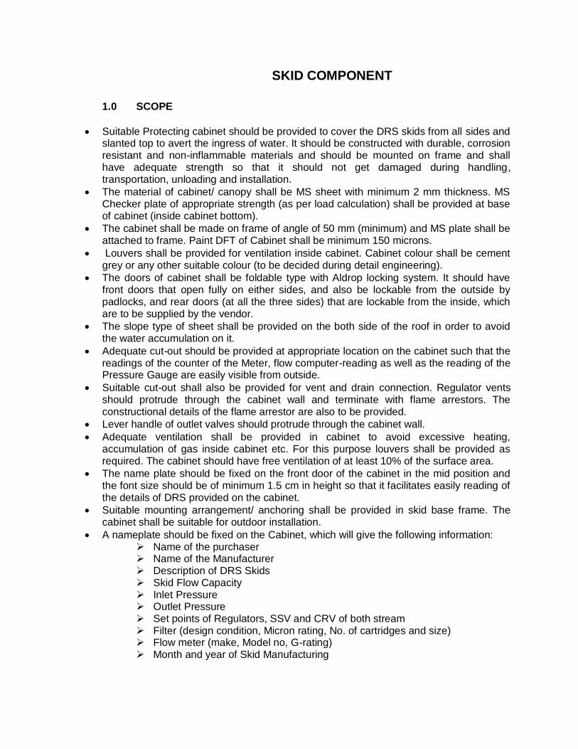
SKID COMPONENT
1.0 SCOPE
Suitable Protecting cabinet should be provided to cover the DRS skids from all sides and slanted top to avert the ingress of water. It should be constructed with durable, corrosion resistant and non-inflammable materials and should be mounted on frame and shall have adequate strength so that it should not get damaged during handling, transportation, unloading and installation.
The material of cabinet/ canopy shall be MS sheet with minimum 2 mm thickness. MS Checker plate of appropriate strength (as per load calculation) shall be provided at base of cabinet (inside cabinet bottom).
The cabinet shall be made on frame of angle of 50 mm (minimum) and MS plate shall be attached to frame. Paint DFT of Cabinet shall be minimum 150 microns.
Louvers shall be provided for ventilation inside cabinet. Cabinet colour shall be cement grey or any other suitable colour (to be decided during detail engineering).
The doors of cabinet shall be foldable type with Aldrop locking system. It should have front doors that open fully on either sides, and also be lockable from the outside by padlocks, and rear doors (at all the three sides) that are lockable from the inside, which are to be supplied by the vendor.
The slope type of sheet shall be provided on the both side of the roof in order to avoid the water accumulation on it.
Adequate cut-out should be provided at appropriate location on the cabinet such that the readings of the counter of the Meter, flow computer-reading as well as the reading of the Pressure Gauge are easily visible from outside.
Suitable cut-out shall also be provided for vent and drain connection. Regulator vents should protrude through the cabinet wall and terminate with flame arrestors. The constructional details of the flame arrestor are also to be provided.
Lever handle of outlet valves should protrude through the cabinet wall.
Adequate ventilation shall be provided in cabinet to avoid excessive heating, accumulation of gas inside cabinet etc. For this purpose louvers shall be provided as required. The cabinet should have free ventilation of at least 10% of the surface area.
The name plate should be fixed on the front door of the cabinet in the mid position and the font size should be of minimum 1.5 cm in height so that it facilitates easily reading of the details of DRS provided on the cabinet.
Suitable mounting arrangement/ anchoring shall be provided in skid base frame. The cabinet shall be suitable for outdoor installation.
A nameplate should be fixed on the Cabinet, which will give the following information: Name of the purchaser Name of the Manufacturer Description of DRS Skids Skid Flow Capacity Inlet Pressure Outlet Pressure Set points of Regulators, SSV and CRV of both stream Filter (design condition, Micron rating, No. of cartridges and size) Flow meter (make, Model no, G-rating) Month and year of Skid Manufacturing
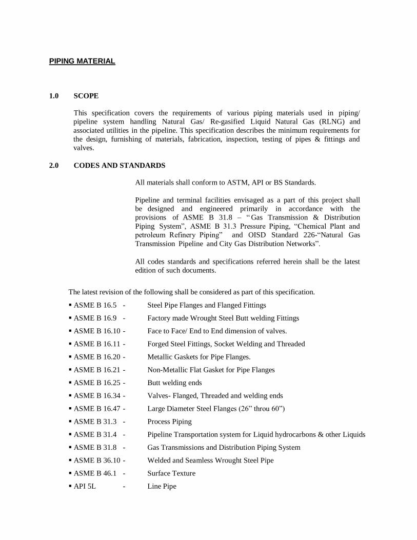
PIPING MATERIAL
1.0 SCOPE
This specification covers the requirements of various piping materials used in piping/
pipeline system handling Natural Gas/ Re-gasified Liquid Natural Gas (RLNG) and
associated utilities in the pipeline. This specification describes the minimum requirements for
the design, furnishing of materials, fabrication, inspection, testing of pipes & fittings and
valves.
2.0 CODES AND STANDARDS
All materials shall conform to ASTM, API or BS Standards.
Pipeline and terminal facilities envisaged as a part of this project shall
be designed and engineered primarily in accordance with the
provisions of ASME B 31.8 – “ Gas Transmission & Distribution
Piping System”, ASME B 31.3 Pressure Piping, “Chemical Plant and
petroleum Refinery Piping” and OISD Standard 226-“Natural Gas
Transmission Pipeline and City Gas Distribution Networks”.
All codes standards and specifications referred herein shall be the latest
edition of such documents.
The latest revision of the following shall be considered as part of this specification.
ASME B 16.5 - Steel Pipe Flanges and Flanged Fittings
ASME B 16.9 - Factory made Wrought Steel Butt welding Fittings
ASME B 16.10 - Face to Face/ End to End dimension of valves.
ASME B 16.11 - Forged Steel Fittings, Socket Welding and Threaded
ASME B 16.20 - Metallic Gaskets for Pipe Flanges.
ASME B 16.21 - Non-Metallic Flat Gasket for Pipe Flanges
ASME B 16.25 - Butt welding ends
ASME B 16.34 - Valves- Flanged, Threaded and welding ends
ASME B 16.47 - Large Diameter Steel Flanges (26” throu 60”)
ASME B 31.3 - Process Piping
ASME B 31.4 - Pipeline Transportation system for Liquid hydrocarbons & other Liquids
ASME B 31.8 - Gas Transmissions and Distribution Piping System
ASME B 36.10 - Welded and Seamless Wrought Steel Pipe
ASME B 46.1 - Surface Texture
API 5L - Line Pipe
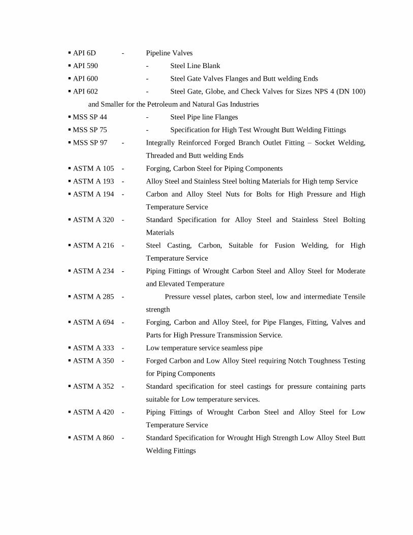
API 6D - Pipeline Valves
API 590 - Steel Line Blank
API 600 - Steel Gate Valves Flanges and Butt welding Ends
API 602 - Steel Gate, Globe, and Check Valves for Sizes NPS 4 (DN 100)
and Smaller for the Petroleum and Natural Gas Industries
MSS SP 44 - Steel Pipe line Flanges
MSS SP 75 - Specification for High Test Wrought Butt Welding Fittings
MSS SP 97 - Integrally Reinforced Forged Branch Outlet Fitting – Socket Welding,
Threaded and Butt welding Ends
ASTM A 105 - Forging, Carbon Steel for Piping Components
ASTM A 193 - Alloy Steel and Stainless Steel bolting Materials for High temp Service
ASTM A 194 - Carbon and Alloy Steel Nuts for Bolts for High Pressure and High
Temperature Service
ASTM A 320 - Standard Specification for Alloy Steel and Stainless Steel Bolting
Materials
ASTM A 216 - Steel Casting, Carbon, Suitable for Fusion Welding, for High
Temperature Service
ASTM A 234 - Piping Fittings of Wrought Carbon Steel and Alloy Steel for Moderate
and Elevated Temperature
ASTM A 285 - Pressure vessel plates, carbon steel, low and intermediate Tensile
strength
ASTM A 694 - Forging, Carbon and Alloy Steel, for Pipe Flanges, Fitting, Valves and
Parts for High Pressure Transmission Service.
ASTM A 333 - Low temperature service seamless pipe
ASTM A 350 - Forged Carbon and Low Alloy Steel requiring Notch Toughness Testing
for Piping Components
ASTM A 352 - Standard specification for steel castings for pressure containing parts
suitable for Low temperature services.
ASTM A 420 - Piping Fittings of Wrought Carbon Steel and Alloy Steel for Low
Temperature Service
ASTM A 860 - Standard Specification for Wrought High Strength Low Alloy Steel Butt
Welding Fittings
3.0 PIPING
3.1 Carbon steel pipe shall be made by open hearth, electric furnace or basic oxygen process
only. The steel used shall be fully killed and made with fine grain structure. The grade and
wall thickness of various sizes of pipes shall be as specified in the P&ID or other bid
documents.
3.2 Pipe dimensions shall be in accordance with ANSI B 36.10 or API 5L for carbon steel pipes.
3.3 For butt weld end, bevel shall be in accordance to ANSI B 16.25/ API 5L as applicable.
3.4 Test reports shall be supplied for all mandatory tests as per the applicable material
specifications.
3.5 Material test certificates (physical property, chemical composition and heat treatment report)
shall also be furnished for the pipes supplied.
3.6 Pipes shall not have any circumferential seam joint in a random length.
3.7 All pipes shall be hydrostatically tested and the test pressure shall be as per QAP or as
specified.
3.8 All pipe threads shall conform to American Standard taper as per ANSI 1.20.1 NPT, unless
otherwise specified.
3.9 All pipe and their dimensions, tolerances, chemical compositions, physical properties, heat
treatment, hydro test and other testing and marking shall confirm to the codes and standards.
3.10 Marking And Dispatch
3.10.1 All pipes shall be marked in accordance with the applicable codes, standards and specifications.
3.10.2 Pipes shall be dry, clean and free from moisture, dirt and loose foreign materials of any kind.
3.10.3 Pipes shall be protected from rust, corrosion and mechanical damage during transportation, shipment and storage.
3.10.4 Steel end protectors to be used on galvanized pipes shall be galvanized.
3.10.5 Both ends of the pipe shall be protected with the following material:
a) Plain end: Plastic cap, b) Bevel end: Wood, metal or plastic cover.
3.10.6 End protectors to be used on beveled ends shall be securely and tightly attached with belt or wire.
4.0 BENDS
Unless otherwise specified for terminal piping, the elbow of radius R = 1.5 D shall only
be used.
5.0 FITTINGS
5.1 Fully killed carbon steel shall be used in the manufacture of fittings.
5.2 Dimension of socket weld/ screwed fittings shall conform to ASME B 16.11
5.3 Fittings thickness tolerances shall match pipe thickness tolerance.
5.4 Bore of socket welded fittings shall suit O. D. of pipe and its thickness.
5.5 For reducing butt weld fittings having different wall thickness at each end, the greater wall
thickness of the fittings shall be employed and inside bore at each end shall be matched with the
specified inside diameter of connecting pipe.
5.6 Chemical composition, physical properties, tests; dimensions and tolerance, heat treatment and
marking shall conform to the applicable codes / standards / specifications as specified.
5.7 All unequal tees are reducing in branch only.
5.8 No repair welding is permitted.
5.9 All fittings shall be seamless in construction unless otherwise specified and as directed by Owner.
5.10 Dimensions of butt welded carbon steel fittings shall be as per ASME B 16.9 / MSS-SP-75,
as applicable.
5.11 Butt welding ends shall conform to ANSI B 16.25/ API 5L. In case of difference in thickness of matching ends, requirements of ASME B 31.8 shall apply.
5.12 Integrally reinforced forged branch fittings such as sockolet, threadolet, weldolet, nippolet etc. shall be as per MSS-SP-97. Fittings not covered in ASME B 16.9 and MSS-SP-97 shall
conform to manufacturer’s standard.
5.13 All fittings MSS-SP Grade to meet LTCS properties at -20 °C and -46 °C or as mentioned in the respective material code and tested accordingly.
5.14 Marking And Dispatch
5.14.1 Each fitting shall be legibly and conspicuously marked in accordance with the requirements of
applicable standards.
5.14.2 Steel die marking shall not be permitted on body of butt weld fittings, except for low stress round
nose die stamping.
5.14.3 Fittings shall be dry, clean and free of moisture, dirt and loose foreign materials of any kind.
5.14.4 Fittings shall be protected from rust, corrosion and mechanical damage during transportation,
shipment and storage.
5.14.5 Rust preventive used on machined surfaces to be welded shall be easily removable with
petroleum solvent of the same shall not be harmful to welding.
5.14.6 Each end of fitting shall be protected with a wood, metal or plastic cover.
5.14.7 Each size of fitting shall be supplied in separate packaging marked with the purchase order no.,
item code no., material specification, size and schedule / thickness / rating, etc.
6.0 FLANGES
6.1 Flange rating shall be same as ANSI B 16.5/ MSS-SP-44/ B 16.47 Series A as specified.
6.2 Dimensions of flanges shall be in accordance with ANSI B 16.5/ B 16.47 Series A, as
applicable.
6.3 Neck of Weld Neck (WN) flanges to suit pipe bore and thickness.
6.4 Bore of Socket Welded (SW) flanges shall suit pipe O.D. and its thickness.
6.5 Sizes for blind flanges shall be indicated by nominal pipe sizes.
6.6 Carbon steel flanges faces shall have smooth finish as indicated in the material
specification. Flanges faces shall have smooth finish to 125-250 micro inches AARH as per
MSS-SP-6.
6.7 Wherever face finish is not mentioned, it shall be serrated spiral / concentric.
6.8 In place of spectacle blinds of size 14” NB and above, a pair of spacer and blind may be used.
6.9 All flanges of size 2" NB & above shall have Butt Weld ends unless otherwise specified.
6.10 Flanges of size 1.5" NB and below shall have socket weld ends unless otherwise specified.
6.11 Butt welding ends of WN flanges shall conform to ANSI B 16.25.
6.12 Spectacle blind/ spacer & blinds shall be in accordance with ASME B 16.48/
Manufacturer’s Standard. Spectacle blind shall be used for sizes up to 8” NB and spacer &
blind for 10” & above shall be used.
6.13 Two jack screws 180° apart shall be provided for all spectacle blind assemblies. The
jack screws shall be as per CONSULTANT/ OWNER’s standard.
6.14 No repair welding is permitted.
6.15 Material test certificate (physical property, chemical composition & heat treatment report, etc.)
shall also be furnished for flanges supplied.
6.16 Marking & Dispatch
All flanges shall be properly marked with item code no. and size and shall be securely placed in
wooden boxes for dispatch
7.0 GASKETS
Spiral wound metallic gaskets (SS 316 – Pure Graphite, Spiral Wound) shall
conform to B 16.20. All spiral wound gaskets shall be provided with inner
and outer (centering) ring.
8.0 BOLTING
8.1 Nuts for stud bolts shall be American Standard Hexagonal Heavy series and double
chamfered.
8.2 Flange bolting shall be fully threaded alloy steel stud bolts with two heavy hex nuts as per the
relevant material standard. All C.S. stud bolts and nuts shall be hot dip galvanized.
8.3 Dimension and tolerances for stud bolts and nuts shall be as per ANSI B 18.2.1 and 18.2.2
with full threading to ANSI B 1.1 Class 2A thread for bolts and Class 2B for nuts.
Diameter and length of stud bolts shall be as per ANSI B 16.5/ ASME B 16.47 with full
threading.
8.4 Threads for nuts shall be as per ANSI B 1.1, as follows:
Nuts for stud dia ¼” to 1” : UNC-2B
Nuts for stud bolts dia 1
1/8” to 3
¼” : 8UN-2B
Threads for stud bolts shall be as per ANSI B 1.1, as follows.
Studs bolts dia ¼” to 1” : UNC-2A
Stud bolts dia 1
1/8” to 3
¼” : 8UN-2A
8.5 Heads of jack screws shall be heavy hexagonal type. Jack screw end shall be rounded. Stud
bolts shall be fully threaded with two hexagonal nuts.
9.0 THREAD SEALANT
Threaded joints shall be made with 1” wide PTFE Jointing tape.
10.0 VALVES
Unless specified otherwise, valves shall conform to the latest edition of following standards:
Screwed / Socket welded / Flanged end valves (1 ½” and below)
Ball Valves - ISO 17292
Plug Valves - BS 5353
Globe Valves - ISO 15761
Gate Valves - API 602
Flanged / Butt weld end Valves (2” and above)
Ball Valves - API 6D
Plug Valves - API 6D
Check Valves - API 6D
Globe Valves - BS 1873
Gate Valves - API 6D All valves with non-metallic seats and seals shall be fire safe type. Fire safe test shall be as per API-
607 (latest) or API-6FA (latest). Fire safe test certificates duly certified by a recognized Third
Party Inspection Agency shall be furnished to the Owner for approval.
The face to face dimensions of flange valves shall be as per ANSI B16.10 and flanges on the steel
flange valves shall conform to ASME B16.5 and ASME B 16.47 as applicable
Butt welding ends of Butt Welded valves shall conform to ANSI B 16.25.
Face-to-face and end-to-end dimensions shall conform to applicable standards.
Buried valves on mainline shall be provided with stem extension, sealant, vent/drain & shall
have butt welded ends.
By pass requirement for Ball valves shall be provided for sizes 4” NB and above. The basic
design of bypass shall be of two valve configuration. One Ball valve (Butt weld type) and one
Globe Valve (Flanged type) on by pass line.
The size of bypass line/valve shall be as under
On main valve =<4” = ½” or more
On main valve >4” but <10” = ¾” or more
On main valve =>10” = 1” or more
The by-pass piping arrangement shall be such that clearance between main valve body and by-
pass assembly shall be the minimum possible for the layout reasons.
Casting of valves shall be radiographically examined as per the procedure and acceptance criteria
specified in ANSI B 16.34 Annexure - B. All valves of ANSI 300# and 150# rating shall be 100%
tested by radiography irrespective of the valve size.
Valve castings not requiring radiography shall be of radiographic quality as per ANSI B16.34 Annexure ‘B’, Radiography for these valve castings shall be carried out by the manufacturer as
per his standard quality control procedure.
Valve body thickness, wherever not specified in the standard, shall be as per ANSI B16.34.
Flange shall be integral with valve body, valves with flanges welded to the body shall not be
accepted.
Socket weld end ball valves with non-metallic seats or seals shall be provided with 100mm long
nipples having material and thickness equivalent to that specified in the piping material class. These nipples shall be welded to the valve by the supplier on both ends before fitting packing
seats and seals.
Ball position indicator shall be provided.
Ball shall be solid in construction.
Ball valves shall be provided with antistatic device.
Ball valves shall be field serviceable.
Ball valves shall meet the Quality Specification Level-3 as per API 6D.
Valves of trunion mounted type shall be double block and bleed type and shall be equipped with a device through which sealant can be injected into the sealant area. Gear operator shall be as under, with position indicators for open/close positions, with limit stops (limit stops are not applicable for gate and globe valves)
For Globe valves - Totally enclosed bevel gear in grease case with grease nipples/plugs
For Ball / Plug valves - Totally enclosed helical worm or combination of helical worm and spur gear in grease case with grease nipples/plugs
Material selection for soft seats/seals for Ball valves shall be suitable for maximum differential pressure, corresponding to pressure/temperature rating and service fluid handled on a continuous
basis. The seat/seal material in valve data sheets for Ball valves is indicative only. Vendor can propose an alternative seat provided he furnishes the pressure/temperature rating of the proposed
seat material which shall cover the class temperature pressure rating of the valve and is superior
to the seat/seal material specified in the valve datasheets.
10.1 Gate and Globe Valves
Globe valve shall be of type BS 1873, bolted bonnet, hard faced stellited conical sheet, taper disc with either flanged ends according to ASME B 16.5/ ASME B 16.47 (as
applicable), or welded ends.
Gate valve shall conform to API 6D with either flanged ends according to ASME B 16.5 /
ASME B 16.47 (as applicable) or welded ends.
The Valve shall be design for maximum pressure of 98 bar(g)/ 49 bar (g)/ 19 bar (g) (as specified
by owner) and a temperature of –20 0
C to + 65 0
C.
The Material of construction of body will be ASTM A350-LF2 / A352 Gr. LCC and the same
should be certified according to the DIN EN 10204 3.2.
All underground valves shall be of extended stem type and Height of the stem shall be decided
during detail engineering. Also, refer QAP and Data sheet attached elsewhere in the bid
document.
10.2 Ball & Plug Valves
Ball of class 300#/ 150# shall be used with full bore, fully welded design / bolted Side entry
design, anti-static tested as per clause B.5 of annexure-B of API 6D, Double block & Bleed
having drain & vent device fire safety, gear operated with hand wheel, local position indicator, ex-
switch for opening and closing suitable for either butt weld ends or flanged connections according to ASME B 16.34, ASME B 16.5 or ASME B 16.47 as applicable.
The ball shall be design for maximum pressure of 98 bar (g)/49 bar(g)/ 19 bar(g) (as specified by
owner) and a temperature of –20 0
C to + 65 0
C.
The Material of construction of body will be ASTM A 350 LF2 CL1 / A 352 LCC and the same
should be certified according to the DIN EN 10204 3.2.
All underground valves shall be of extended stem type and Height of the stem shall be decided during detail engineering.
Also refer QAP and data sheet.
Manual Valve operation shall be as indicated below, unless specified otherwise in the P&ID.
For ANSI class 150#, 300#– hand wheel operated for size <4”NB. Gear operated for size >6”NB.
10.3 Check Valves Description
Material of construction of body will be A 352 Gr. LCC / A 350 LF2, swing check valve, 11-13%
chrome trim, bolted cap, renewable seat, satellite faced seat and disc. (Size 2” thru 16”).
The Valve shall be design for maximum pressure of 98 bar (g) / 49 bar (g)/ 19 bar (g) (as
specified by owner) and a temperature of –20 0
C to + 65 0
C.
The Material of construction will be carbon steel – ASTM A350 – LF2 / A 352 Gr. LCC and the
same should be certified according to the DIN EN 10204 3.2. Also, refer QAP attached elsewhere in the bid.
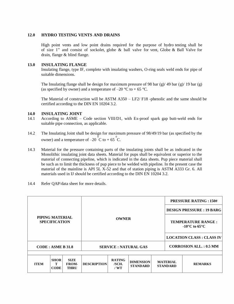
12.0 HYDRO TESTING VENTS AND DRAINS
High point vents and low point drains required for the purpose of hydro testing shall be
of size 1” and consist of sockolet, globe & ball valve for vent, Globe & Ball Valve for
drain, flange & blind flange.
13.0 INSULATING FLANGE Insulating flange, type IF, complete with insulating washers, O-ring seals weld ends for pipe of
suitable dimensions.
The Insulating flange shall be design for maximum pressure of 98 bar (g)/ 49 bar (g)/ 19 bar (g)
(as specified by owner) and a temperature of –20 °C to + 65 °C.
The Material of construction will be ASTM A350 – LF2/ F18 -phenolic and the same should be
certified according to the DIN EN 10204 3.2.
14.0 INSULATING JOINT
14.1 According to ASME – Code section VIII/D1, with Ex-proof spark gap butt-weld ends for
suitable pipe connection, as applicable.
14.2 The Insulating Joint shall be design for maximum pressure of 98/49/19 bar (as specified by the
owner) and a temperature of –20 0
C to + 65 0
C.
14.3 Material for the pressure containing parts of the insulating joints shall be as indicated in the Monolithic insulating joint data sheets. Material for pups shall be equivalent or superior to the
material of connecting pipeline, which is indicated in the data sheets. Pup piece material shall
be such as to limit the thickness of pup piece to be welded with pipeline. In the present case the
material of the mainline is API 5L X-52 and that of station piping is ASTM A333 Gr. 6. All materials used in IJ should be certified according to the DIN EN 10204 3.2.
14.4 Refer QAP/data sheet for more details.
PIPING MATERIAL
SPECIFICATION OWNER
PRESSURE RATING : 150#
DESIGN PRESSURE : 19 BARG
TEMPERATURE RANGE :
-10°C to 65°C
LOCATION CLASS : CLASS IV
CODE : ASME B 31.8 SERVICE : NATURAL GAS CORROSION ALL. : 0.5 MM
ITEM SHOR
T
CODE
SIZE
FROM-
THRU DESCRIPTION
RATING
/SCH.
/ WT
DIMENSION
STANDARD
MATERIAL
STANDARD REMARKS
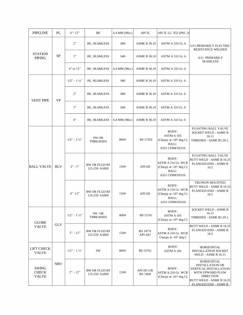
PIPELINE PL 4”- 12” BE 6.4 MM (Min.) API 5L API 5L Gr. X52 (PSL 2)
U/G-PRIMARILY ELECTRIC
RESISTANCE WELDED
A/G- PRIMARILY
SEAMLESS
STATION PIPING
SP
2” BE, SEAMLESS S80 ASME B 36.10 ASTM A 333 Gr. 6
3” BE, SEAMLESS S40 ASME B 36.10 ASTM A 333 Gr. 6
4” to 12” BE, SEAMLESS 6.4 MM (Min.) ASME B 36.10 ASTM A 333 Gr. 6
VENT PIPE VP
1/2" – 1 ½" PE, SEAMLESS S80 ASME B 36.10 ASTM A 333 Gr. 6
2” BE, SEAMLESS S80 ASME B 36.10 ASTM A 333 Gr. 6
3” BE, SEAMLESS S40 ASME B 36.10 ASTM A 333 Gr. 6
4” BE, SEAMLESS 6.4 MM (Min.) ASME B 36.10 ASTM A 333 Gr. 6
BALL VALVE BLV
1/2" – 1 ½" SW OR
THREADED 800# BS 17292
BODY:
ASTM A 105
(Charpy at -10° deg C)
BALL:
A351 CF8M/SS316
FLOATING BALL VALVE
SOCKET WELD - ASME B
16.11
THREDED - ASME B1.20.1.
2” - 3” BW OR FLGD RF
125-250 AARH 150# API 6D
BODY:
ASTM A 216 Gr. WCB
(Charpy at -10° deg C)
BALL:
A351 CF8M/SS316
FLOATING BALL VALVE
BUTT WELD - ASME B 16.25
FLANGED END - ASME B
16.5
4” -12” BW OR FLGD RF
125-250 AARH 150# API 6D
BODY:
ASTM A 216 Gr. WCB
(Charpy at -10° deg C)
BALL:
A351 CF8M/SS316
TRUNION MOUNTED
BUTT WELD - ASME B 16.25
FLANGED END - ASME B
16.5
GLOBE VALVE
GLV
1/2" – 1 ½" SW OR
THREADED 800# BS 15761
BODY:
ASTM A 105
(Charpy at -10° deg C)
SOCKET WELD - ASME B
16.11
THREDED - ASME B1.20.1.
2” – 12” BW OR FLGD RF
125-250 AARH 150#
BS 1873/
API 602
BODY:
ASTM A 216 Gr. WCB
Charpy at -10° deg C
BUTT WELD - ASME B 16.25
FLANGED END - ASME B
16.5
LIFT CHECK VALVE
NRV
1/2" – 1 ½" SW 800# BS 15761
BODY:
ASTM A 105
HORIZONTAL
INSTALLATION SOCKET
WELD - ASME B 16.11
SWING CHECK VALVE
2” – 12” BW OR FLGD RF
125-250 AARH 150#
API 6D OR
BS 1868
BODY:
ASTM A 216 Gr. WCB
(Charpy at -10° deg C)
HORIZONTAL
INSTALLATION OR
VERTICAL INSTALLATION
WITH UPWARD FLOW
DIRECTION
BUTT WELD - ASME B 16.25
FLANGED END - ASME B
16.5
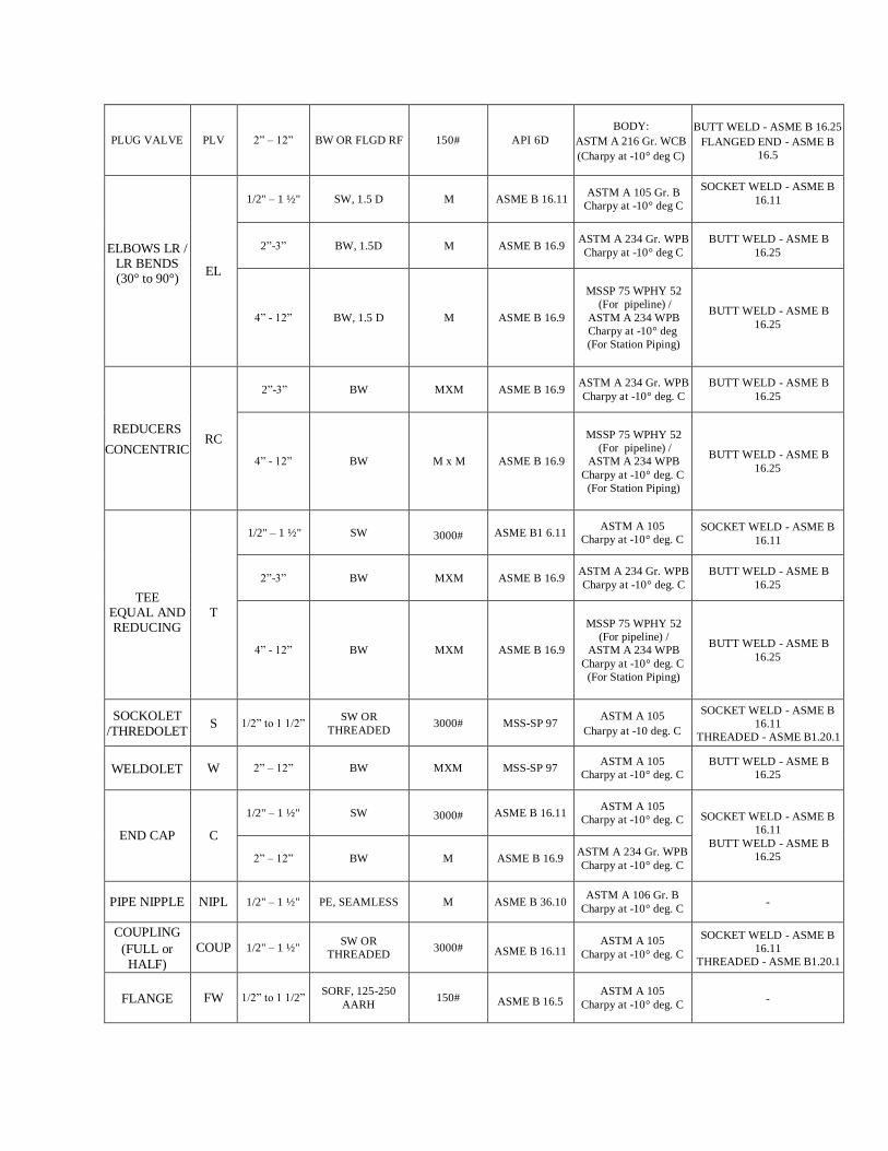
PLUG VALVE PLV 2” – 12” BW OR FLGD RF 150# API 6D
BODY:
ASTM A 216 Gr. WCB
(Charpy at -10° deg C)
BUTT WELD - ASME B 16.25
FLANGED END - ASME B
16.5
ELBOWS LR / LR BENDS (30° to 90°)
EL
1/2" – 1 ½" SW, 1.5 D M ASME B 16.11 ASTM A 105 Gr. B
Charpy at -10° deg C
SOCKET WELD - ASME B
16.11
2”-3” BW, 1.5D M ASME B 16.9 ASTM A 234 Gr. WPB
Charpy at -10° deg C
BUTT WELD - ASME B
16.25
4” - 12” BW, 1.5 D M ASME B 16.9
MSSP 75 WPHY 52
(For pipeline) /
ASTM A 234 WPB
Charpy at -10° deg
(For Station Piping)
BUTT WELD - ASME B
16.25
REDUCERS
CONCENTRIC RC
2”-3” BW MXM ASME B 16.9 ASTM A 234 Gr. WPB
Charpy at -10° deg. C
BUTT WELD - ASME B
16.25
4” - 12” BW M x M ASME B 16.9
MSSP 75 WPHY 52
(For pipeline) /
ASTM A 234 WPB
Charpy at -10° deg. C
(For Station Piping)
BUTT WELD - ASME B
16.25
TEE
EQUAL AND REDUCING
T
1/2" – 1 ½" SW 3000# ASME B1 6.11 ASTM A 105
Charpy at -10° deg. C SOCKET WELD - ASME B
16.11
2”-3” BW MXM ASME B 16.9 ASTM A 234 Gr. WPB
Charpy at -10° deg. C
BUTT WELD - ASME B
16.25
4” - 12” BW MXM ASME B 16.9
MSSP 75 WPHY 52
(For pipeline) /
ASTM A 234 WPB
Charpy at -10° deg. C
(For Station Piping)
BUTT WELD - ASME B
16.25
SOCKOLET
/THREDOLET S 1/2” to 1 1/2”
SW OR
THREADED 3000# MSS-SP 97
ASTM A 105
Charpy at -10 deg. C
SOCKET WELD - ASME B
16.11
THREADED - ASME B1.20.1
WELDOLET W 2” – 12” BW MXM MSS-SP 97 ASTM A 105
Charpy at -10° deg. C
BUTT WELD - ASME B
16.25
END CAP C
1/2" – 1 ½" SW 3000# ASME B 16.11 ASTM A 105
Charpy at -10° deg. C SOCKET WELD - ASME B
16.11
BUTT WELD - ASME B
16.25 2” – 12” BW M ASME B 16.9 ASTM A 234 Gr. WPB
Charpy at -10° deg. C
PIPE NIPPLE NIPL 1/2" – 1 ½" PE, SEAMLESS M ASME B 36.10 ASTM A 106 Gr. B
Charpy at -10° deg. C -
COUPLING
(FULL or
HALF)
COUP 1/2" – 1 ½" SW OR
THREADED 3000# ASME B 16.11
ASTM A 105
Charpy at -10° deg. C
SOCKET WELD - ASME B
16.11
THREADED - ASME B1.20.1
FLANGE FW 1/2” to 1 1/2” SORF, 125-250
AARH 150# ASME B 16.5
ASTM A 105
Charpy at -10° deg. C -
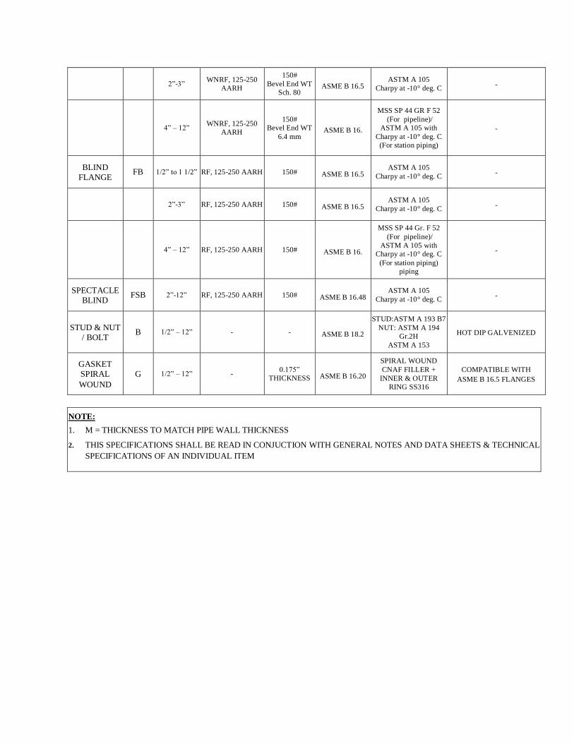
2”-3” WNRF, 125-250
AARH
150#
Bevel End WT
Sch. 80 ASME B 16.5
ASTM A 105
Charpy at -10° deg. C -
4” – 12” WNRF, 125-250
AARH
150#
Bevel End WT
6.4 mm ASME B 16.
MSS SP 44 GR F 52
(For pipeline)/
ASTM A 105 with
Charpy at -10° deg. C
(For station piping)
-
BLIND
FLANGE FB 1/2” to 1 1/2” RF, 125-250 AARH 150# ASME B 16.5
ASTM A 105
Charpy at -10° deg. C -
2”-3” RF, 125-250 AARH 150# ASME B 16.5 ASTM A 105
Charpy at -10° deg. C -
4” – 12” RF, 125-250 AARH 150# ASME B 16.
MSS SP 44 Gr. F 52
(For pipeline)/
ASTM A 105 with
Charpy at -10° deg. C
(For station piping)
piping
-
SPECTACLE
BLIND FSB 2”-12” RF, 125-250 AARH 150# ASME B 16.48
ASTM A 105
Charpy at -10° deg. C -
STUD & NUT
/ BOLT B 1/2” – 12” - - ASME B 18.2
STUD:ASTM A 193 B7
NUT: ASTM A 194
Gr.2H
ASTM A 153
HOT DIP GALVENIZED
GASKET
SPIRAL
WOUND
G 1/2” – 12” - 0.175”
THICKNESS ASME B 16.20
SPIRAL WOUND
CNAF FILLER +
INNER & OUTER
RING SS316
COMPATIBLE WITH
ASME B 16.5 FLANGES
NOTE:
1. M = THICKNESS TO MATCH PIPE WALL THICKNESS
2. THIS SPECIFICATIONS SHALL BE READ IN CONJUCTION WITH GENERAL NOTES AND DATA SHEETS & TECHNICAL
SPECIFICATIONS OF AN INDIVIDUAL ITEM
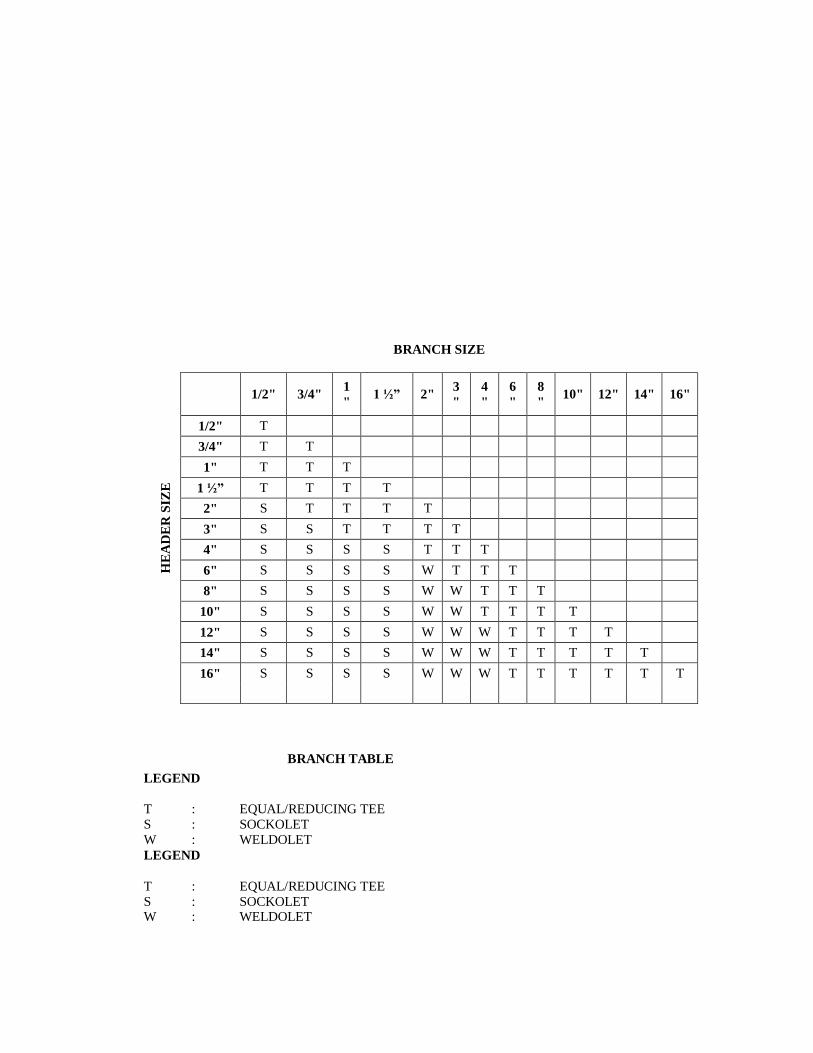
BRANCH TABLE
LEGEND
T : EQUAL/REDUCING TEE
S : SOCKOLET
W : WELDOLET
LEGEND
T : EQUAL/REDUCING TEE
S : SOCKOLET W : WELDOLET
BRANCH SIZE
HE
AD
ER
SIZ
E
1/2" 3/4"
1
" 1 ½” 2"
3
"
4
"
6
"
8
" 10" 12" 14" 16"
1/2" T
3/4" T T
1" T T T
1 ½” T T T T
2" S T T T T
3" S S T T T T
4" S S S S T T T
6" S S S S W T T T
8" S S S S W W T T T
10" S S S S W W T T T T
12" S S S S W W W T T T T
14" S S S S W W W T T T T T
16" S S S S W W W T T T T T T
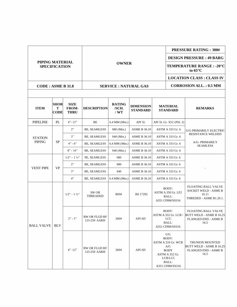
PIPING MATERIAL
SPECIFICATION OWNER
PRESSURE RATING : 300#
DESIGN PRESSURE : 49 BARG
TEMPERATURE RANGE : -20°C
to 65°C
LOCATION CLASS : CLASS IV
CODE : ASME B 31.8 SERVICE : NATURAL GAS CORROSION ALL. : 0.5 MM
ITEM SHOR
T
CODE
SIZE
FROM-
THRU DESCRIPTION
RATING
/SCH.
/ WT
DIMENSION
STANDARD
MATERIAL
STANDARD REMARKS
PIPELINE PL 4”- 12” BE 6.4 MM (Min.) API 5L API 5L Gr. X52 (PSL 2)
U/G-PRIMARILY ELECTRIC
RESISTANCE WELDED
A/G- PRIMARILY
SEAMLESS
STATION PIPING
SP
2” BE, SEAMLESS S80 (Min.) ASME B 36.10 ASTM A 333 Gr. 6
3” BE, SEAMLESS S40 (Min.) ASME B 36.10 ASTM A 333 Gr. 6
4” - 6” BE, SEAMLESS 6.4 MM (Min.) ASME B 36.10 ASTM A 333 Gr. 6
8” - 16” BE, SEAMLESS S40 (Min.) ASME B 36.10 ASTM A 333 Gr. 6
VENT PIPE VP
1/2" – 1 ½" PE, SEAMLESS S80 ASME B 36.10 ASTM A 333 Gr. 6
-
2” BE, SEAMLESS S80 ASME B 36.10 ASTM A 333 Gr. 6
3” BE, SEAMLESS S40 ASME B 36.10 ASTM A 333 Gr. 6
4” BE, SEAMLESS 6.4 MM (Min.) ASME B 36.10 ASTM A 333 Gr. 6
BALL VALVE BLV
1/2" – 1 ½" SW OR
THREADED 800# BS 17292
BODY:
ASTM A 350 Gr. LF2
BALL:
A351 CF8M/SS316
FLOATING BALL VALVE
SOCKET WELD - ASME B
16.11
THREDED - ASME B1.20.1.
2” - 3” BW OR FLGD RF
125-250 AARH 300# API 6D
BODY:
ASTM A 352 Gr. LCB /
LCC
BALL:
A351 CF8M/SS316
FLOATING BALL VALVE
BUTT WELD - ASME B 16.25
FLANGED END - ASME B
16.5
4” -12” BW OR FLGD RF
125-250 AARH 300# API 6D
U/G
BODY:
ASTM A 216 Gr. WCB
A/G
BODY
ASTM A 352 Gr.
LCB/LCC
BALL:
A351 CF8M/SS316
TRUNION MOUNTED
BUTT WELD - ASME B 16.25
FLANGED END - ASME B
16.5
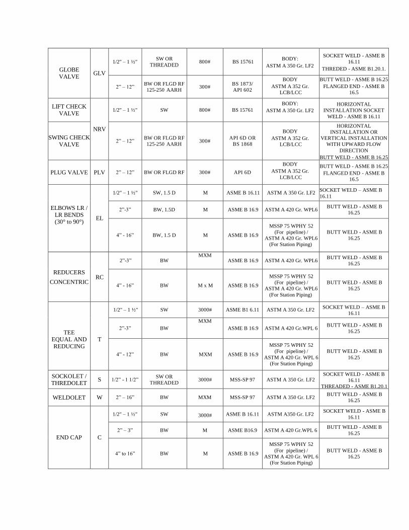
GLOBE VALVE
GLV
1/2" – 1 ½" SW OR
THREADED 800# BS 15761
BODY:
ASTM A 350 Gr. LF2
SOCKET WELD - ASME B
16.11
THREDED - ASME B1.20.1.
2” – 12” BW OR FLGD RF
125-250 AARH 300#
BS 1873/
API 602
BODY
ASTM A 352 Gr.
LCB/LCC
BUTT WELD - ASME B 16.25
FLANGED END - ASME B
16.5
LIFT CHECK VALVE
NRV
1/2" – 1 ½" SW 800# BS 15761
BODY:
ASTM A 350 Gr. LF2
HORIZONTAL
INSTALLATION SOCKET
WELD - ASME B 16.11
SWING CHECK VALVE
2” – 12” BW OR FLGD RF
125-250 AARH 300#
API 6D OR
BS 1868
BODY
ASTM A 352 Gr.
LCB/LCC
HORIZONTAL
INSTALLATION OR
VERTICAL INSTALLATION
WITH UPWARD FLOW
DIRECTION
BUTT WELD - ASME B 16.25
FLANGED END - ASME B
16.5
PLUG VALVE PLV 2” – 12” BW OR FLGD RF 300# API 6D
BODY
ASTM A 352 Gr.
LCB/LCC
BUTT WELD - ASME B 16.25
FLANGED END - ASME B
16.5
ELBOWS LR / LR BENDS (30° to 90°)
EL
1/2" – 1 ½" SW, 1.5 D M ASME B 16.11 ASTM A 350 Gr. LF2 SOCKET WELD – ASME B
16.11
2”-3” BW, 1.5D M ASME B 16.9 ASTM A 420 Gr. WPL6 BUTT WELD - ASME B
16.25
4” - 16” BW, 1.5 D M ASME B 16.9
MSSP 75 WPHY 52
(For pipeline) /
ASTM A 420 Gr. WPL6
(For Station Piping)
BUTT WELD - ASME B
16.25
REDUCERS
CONCENTRIC RC
2”-3” BW MXM
ASME B 16.9 ASTM A 420 Gr. WPL6 BUTT WELD - ASME B
16.25
4” - 16” BW M x M ASME B 16.9
MSSP 75 WPHY 52
(For pipeline) /
ASTM A 420 Gr. WPL6
(For Station Piping)
BUTT WELD - ASME B
16.25
TEE
EQUAL AND REDUCING
T
1/2" – 1 ½" SW 3000# ASME B1 6.11 ASTM A 350 Gr. LF2 SOCKET WELD – ASME B
16.11
2”-3” BW
MXM ASME B 16.9 ASTM A 420 Gr.WPL 6
BUTT WELD - ASME B
16.25
4” - 12” BW MXM ASME B 16.9
MSSP 75 WPHY 52
(For pipeline) /
ASTM A 420 Gr. WPL 6
(For Station Piping)
BUTT WELD - ASME B
16.25
SOCKOLET / THREDOLET
S 1/2” - 1 1/2” SW OR
THREADED 3000# MSS-SP 97 ASTM A 350 Gr. LF2
SOCKET WELD - ASME B
16.11
THREADED - ASME B1.20.1
WELDOLET W 2” – 16” BW MXM MSS-SP 97 ASTM A 350 Gr. LF2 BUTT WELD - ASME B
16.25
END CAP C
1/2" – 1 ½" SW 3000# ASME B 16.11 ASTM A350 Gr. LF2 SOCKET WELD - ASME B
16.11
2” – 3” BW M ASME B16.9 ASTM A 420 Gr.WPL 6 BUTT WELD - ASME B
16.25
4” to 16” BW M ASME B 16.9
MSSP 75 WPHY 52
(For pipeline) /
ASTM A 420 Gr. WPL 6
(For Station Piping)
BUTT WELD - ASME B
16.25
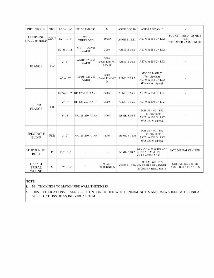
PIPE NIPPLE NIPL 1/2" – 1 ½" PE, SEAMLESS M ASME B 36.10 ASTM A 333 Gr. 6 -
COUPLING
(FULL or HALF COUP 1/2" – 1 ½"
SW OR
THREADED 3000# ASME B 16.11 ASTM A 350 Gr. LF2
SOCKET WELD - ASME B
16.11
THREADED - ASME B1.20.1
FLANGE FW
1/2” to 1 1/2” SORF, 125-250
AARH 300# ASME B 16.5 ASTM A 350 Gr. LF2 -
2”-3” WNRF, 125-250
AARH
300#
Bevel End WT
Sch. 80
ASME B 16.5 ASTM A 350 Gr. LF2 -
4” to 16” WNRF, 125-250
AARH
300#
Bevel End WT
M
ASME B 16.5
MSS SP 44 GR 52
(For pipeline)/
ASTM A 350 Gr. LF2
(For station piping)
-
BLIND FLANGE
FB
1/2” to 1 1/2” RF, 125-250 AARH 300# ASME B 16.5 ASTM A 350 Gr. LF2 -
2”-3” RF, 125-250 AARH 300# ASME B 16.5 ASTM A 350 Gr. LF2 -
4”-16” RF, 125-250 AARH 300# ASME B 16.5
MSS SP 44 Gr. F52
(For pipeline)/
ASTM A 350 Gr. LF2
(For station piping)
-
SPECTACLE BLIND
FSB 2-12” RF, 125-250 AARH 300# ASME B 16.48
MSS SP 44 Gr. F52
(For pipeline)/
ASTM A 350 Gr. LF2
(For station piping)
-
STUD & NUT / BOLT
B 1/2” – 16” - - ASME B 18.2
STUD:ASTM A 193 Gr.7
NUT: ASTM A 320
Gr.L7 ASTM A 153
HOT DIP GALVENIZED
GASKET SPIRAL WOUND
G
1/2” – 16” -
0.175”
THICKNESS ASME B 16.20
SPIRAL WOUND
CNAF FILLER + INNER
& OUTER RING SS316
COMPATIBLE WITH
ASME B 16.5 FLANGES
NOTE:
1. M = THICKNESS TO MATCH PIPE WALL THICKNESS
2. THIS SPECIFICATIONS SHALL BE READ IN CONJUCTION WITH GENERAL NOTES AND DATA SHEETS & TECHNICAL
SPECIFICATIONS OF AN INDIVIDUAL ITEM
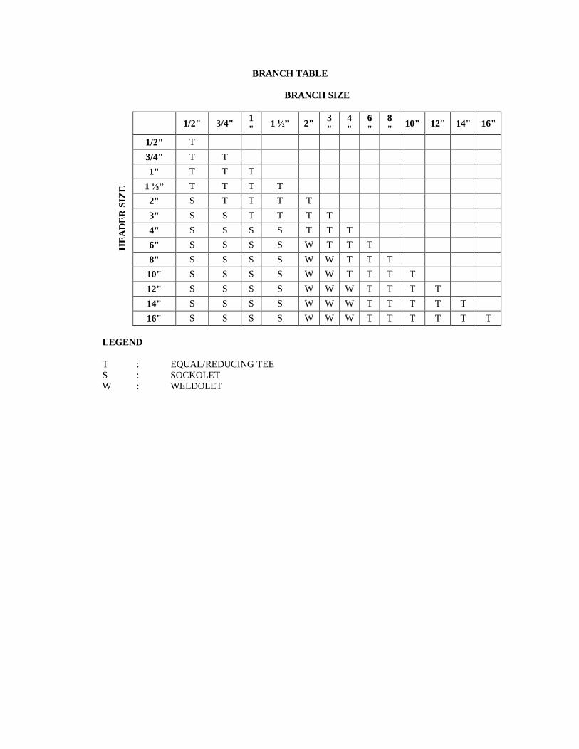
BRANCH TABLE
BRANCH SIZE
HE
AD
ER
SIZ
E
1/2" 3/4"
1
" 1 ½” 2"
3
"
4
"
6
"
8
" 10" 12" 14" 16"
1/2" T
3/4" T T
1" T T T
1 ½” T T T T
2" S T T T T
3" S S T T T T
4" S S S S T T T
6" S S S S W T T T
8" S S S S W W T T T
10" S S S S W W T T T T
12" S S S S W W W T T T T
14" S S S S W W W T T T T T
16" S S S S W W W T T T T T T
LEGEND
T : EQUAL/REDUCING TEE
S : SOCKOLET
W : WELDOLET
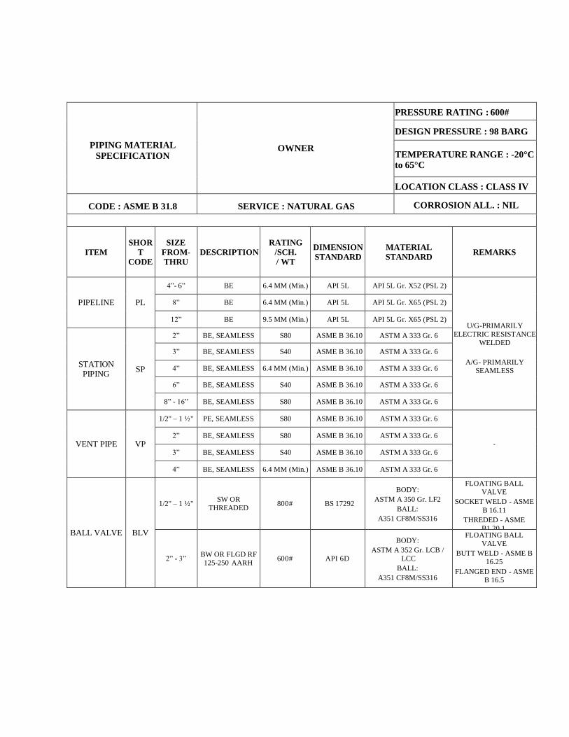
PIPING MATERIAL
SPECIFICATION OWNER
PRESSURE RATING : 600#
DESIGN PRESSURE : 98 BARG
TEMPERATURE RANGE : -20°C
to 65°C
LOCATION CLASS : CLASS IV
CODE : ASME B 31.8 SERVICE : NATURAL GAS CORROSION ALL. : NIL
ITEM SHOR
T
CODE
SIZE
FROM-
THRU DESCRIPTION
RATING
/SCH.
/ WT
DIMENSION
STANDARD
MATERIAL
STANDARD REMARKS
PIPELINE PL
4”- 6” BE 6.4 MM (Min.) API 5L API 5L Gr. X52 (PSL 2)
U/G-PRIMARILY
ELECTRIC RESISTANCE
WELDED
A/G- PRIMARILY
SEAMLESS
8” BE 6.4 MM (Min.) API 5L API 5L Gr. X65 (PSL 2)
12” BE 9.5 MM (Min.) API 5L API 5L Gr. X65 (PSL 2)
STATION PIPING
SP
2” BE, SEAMLESS S80 ASME B 36.10 ASTM A 333 Gr. 6
3” BE, SEAMLESS S40 ASME B 36.10 ASTM A 333 Gr. 6
4” BE, SEAMLESS 6.4 MM (Min.) ASME B 36.10 ASTM A 333 Gr. 6
6” BE, SEAMLESS S40 ASME B 36.10 ASTM A 333 Gr. 6
8” - 16” BE, SEAMLESS S80 ASME B 36.10 ASTM A 333 Gr. 6
VENT PIPE
VP
1/2" – 1 ½" PE, SEAMLESS S80 ASME B 36.10 ASTM A 333 Gr. 6
-
2” BE, SEAMLESS S80 ASME B 36.10 ASTM A 333 Gr. 6
3” BE, SEAMLESS S40 ASME B 36.10 ASTM A 333 Gr. 6
4” BE, SEAMLESS 6.4 MM (Min.) ASME B 36.10 ASTM A 333 Gr. 6
BALL VALVE BLV
1/2" – 1 ½" SW OR
THREADED 800# BS 17292
BODY:
ASTM A 350 Gr. LF2
BALL:
A351 CF8M/SS316
FLOATING BALL
VALVE
SOCKET WELD - ASME
B 16.11
THREDED - ASME
B1.20.1.
2” - 3” BW OR FLGD RF
125-250 AARH 600# API 6D
BODY:
ASTM A 352 Gr. LCB /
LCC
BALL:
A351 CF8M/SS316
FLOATING BALL
VALVE
BUTT WELD - ASME B
16.25
FLANGED END - ASME
B 16.5
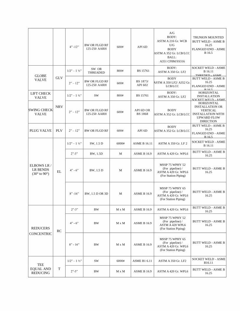
4” -12” BW OR FLGD RF
125-250 AARH 600# API 6D
A/G
BODY:
ASTM A 216 Gr. WCB
U/G
BODY
ASTM A 352 Gr. LCB/LCC
BALL:
A351 CF8M/SS316
TRUNION MOUNTED
BUTT WELD - ASME B
16.25
FLANGED END - ASME
B 16.5
GLOBE VALVE
GLV
1/2" – 1 ½" SW OR
THREADED 800# BS 15761
BODY:
ASTM A 350 Gr. LF2
SOCKET WELD - ASME
B 16.11
THREDED - ASME
B1.20.1.
2” – 12” BW OR FLGD RF
125-250 AARH 600#
BS 1873/
API 602
BODY
ASTM A 350 LF2/ A352 Gr.
LCB/LCC
BUTT WELD - ASME B
16.25
FLANGED END - ASME
B 16.5
LIFT CHECK
VALVE
NRV
1/2" – 1 ½" SW 800# BS 15761 BODY:
ASTM A 350 Gr. LF2
HORIZONTAL
INSTALLATION
SOCKET WELD - ASME
B 16.11
SWING CHECK
VALVE 2” – 12”
BW OR FLGD RF
125-250 AARH 600#
API 6D OR
BS 1868
BODY
ASTM A 352 Gr. LCB/LCC
HORIZONTAL
INSTALLATION OR
VERTICAL
INSTALLATION WITH
UPWARD FLOW
DIRECTION
BUTT WELD - ASME B
16.25
FLANGED END - ASME
B 16.5
PLUG VALVE PLV 2” – 12” BW OR FLGD RF 600# API 6D
BODY
ASTM A 352 Gr. LCB/LCC
BUTT WELD - ASME B
16.25
FLANGED END - ASME
B 16.5
ELBOWS LR /
LR BENDS (30° to 90°)
EL
1/2" – 1 ½" SW, 1.5 D 6000# ASME B 16.11 ASTM A 350 Gr. LF 2 SOCKET WELD - ASME
B 16.11
2”-3” BW, 1.5D M ASME B 16.9 ASTM A 420 Gr. WPL6 BUTT WELD - ASME B
16.25
4” - 6” BW, 1.5 D M ASME B 16.9
MSSP 75 WPHY 52
(For pipeline) /
ASTM A 420 Gr. WPL6
(For Station Piping)
BUTT WELD - ASME B
16.25
8” -16” BW, 1.5 D OR 3D M ASME B 16.9
MSSP 75 WPHY 65
(For pipeline) /
ASTM A 420 Gr. WPL6
(For Station Piping)
BUTT WELD - ASME B
16.25
REDUCERS
CONCENTRIC RC
2”-3” BW M x M ASME B 16.9 ASTM A 420 Gr. WPL6 BUTT WELD - ASME B
16.25
4” - 6” BW M x M ASME B 16.9
MSSP 75 WPHY 52
(For pipeline) /
ASTM A 420 WPL6
(For Station Piping)
BUTT WELD - ASME B
16.25
8” - 16” BW M x M ASME B 16.9
MSSP 75 WPHY 65
(For pipeline) /
ASTM A 420 Gr. WPL6
(For Station Piping)
BUTT WELD - ASME B
16.25
TEE
EQUAL AND REDUCING
T
1/2" – 1 ½" SW 6000# ASME B1 6.11 ASTM A 350 Gr. LF2 SOCKET WELD - ASME
B16.11
2”-3” BW M x M ASME B 16.9 ASTM A 420 Gr. WPL6 BUTT WELD - ASME B
16.25
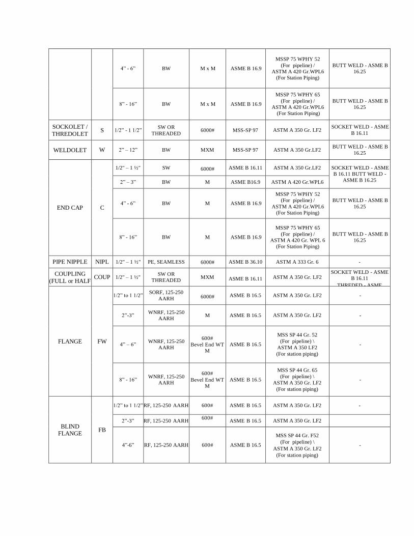
4” - 6” BW M x M ASME B 16.9
MSSP 75 WPHY 52
(For pipeline) /
ASTM A 420 Gr.WPL6
(For Station Piping)
BUTT WELD - ASME B
16.25
8” - 16” BW M x M ASME B 16.9
MSSP 75 WPHY 65
(For pipeline) /
ASTM A 420 Gr.WPL6
(For Station Piping)
BUTT WELD - ASME B
16.25
SOCKOLET /
THREDOLET S 1/2” - 1 1/2”
SW OR
THREADED 6000# MSS-SP 97 ASTM A 350 Gr. LF2
SOCKET WELD - ASME
B 16.11
WELDOLET W 2” – 12” BW MXM MSS-SP 97 ASTM A 350 Gr.LF2 BUTT WELD - ASME B
16.25
END CAP C
1/2" – 1 ½" SW 6000# ASME B 16.11 ASTM A 350 Gr.LF2 SOCKET WELD - ASME
B 16.11 BUTT WELD -
ASME B 16.25 2” – 3” BW M ASME B16.9 ASTM A 420 Gr.WPL6
4” - 6” BW M ASME B 16.9
MSSP 75 WPHY 52
(For pipeline) /
ASTM A 420 Gr.WPL6
(For Station Piping)
BUTT WELD - ASME B
16.25
8” - 16” BW M ASME B 16.9
MSSP 75 WPHY 65
(For pipeline) /
ASTM A 420 Gr. WPL 6
(For Station Piping)
BUTT WELD - ASME B
16.25
PIPE NIPPLE NIPL 1/2" – 1 ½" PE, SEAMLESS 6000# ASME B 36.10 ASTM A 333 Gr. 6 -
COUPLING
(FULL or HALF COUP 1/2" – 1 ½"
SW OR
THREADED MXM ASME B 16.11 ASTM A 350 Gr. LF2
SOCKET WELD - ASME
B 16.11
THREDED - ASME
B1.20.1
FLANGE FW
1/2” to 1 1/2” SORF, 125-250
AARH 6000# ASME B 16.5 ASTM A 350 Gr. LF2 -
2”-3” WNRF, 125-250
AARH M ASME B 16.5 ASTM A 350 Gr. LF2 -
4” – 6” WNRF, 125-250
AARH
600#
Bevel End WT
M
ASME B 16.5
MSS SP 44 Gr. 52
(For pipeline) \
ASTM A 350 LF2
(For station piping)
-
8” - 16” WNRF, 125-250
AARH
600#
Bevel End WT
M
ASME B 16.5
MSS SP 44 Gr. 65
(For pipeline) \
ASTM A 350 Gr. LF2
(For station piping)
-
BLIND FLANGE
FB
1/2” to 1 1/2” RF, 125-250 AARH 600# ASME B 16.5 ASTM A 350 Gr. LF2 -
2”-3” RF, 125-250 AARH 600#
ASME B 16.5 ASTM A 350 Gr. LF2
4”-6” RF, 125-250 AARH 600# ASME B 16.5
MSS SP 44 Gr. F52
(For pipeline) \
ASTM A 350 Gr. LF2
(For station piping)
-
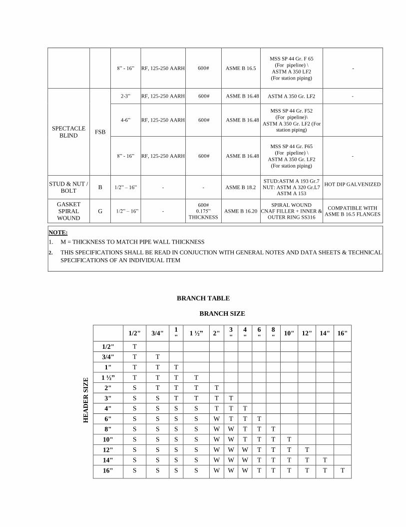
8” - 16” RF, 125-250 AARH 600# ASME B 16.5
MSS SP 44 Gr. F 65
(For pipeline) \
ASTM A 350 LF2
(For station piping)
-
SPECTACLE
BLIND FSB
2-3” RF, 125-250 AARH 600# ASME B 16.48 ASTM A 350 Gr. LF2 -
4-6” RF, 125-250 AARH 600# ASME B 16.48
MSS SP 44 Gr. F52
(For pipeline)\
ASTM A 350 Gr. LF2 (For
station piping)
8” - 16” RF, 125-250 AARH 600# ASME B 16.48
MSS SP 44 Gr. F65
(For pipeline) \
ASTM A 350 Gr. LF2
(For station piping)
-
STUD & NUT / BOLT
B 1/2” – 16” - - ASME B 18.2
STUD:ASTM A 193 Gr.7
NUT: ASTM A 320 Gr.L7
ASTM A 153
HOT DIP GALVENIZED
GASKET SPIRAL WOUND
G 1/2” – 16” -
600#
0.175”
THICKNESS
ASME B 16.20
SPIRAL WOUND
CNAF FILLER + INNER &
OUTER RING SS316
COMPATIBLE WITH
ASME B 16.5 FLANGES
BRANCH TABLE
BRANCH SIZE
HE
AD
ER
SIZ
E
1/2" 3/4"
1
" 1 ½” 2"
3
"
4
"
6
"
8
" 10" 12" 14" 16"
1/2" T
3/4" T T
1" T T T
1 ½” T T T T
2" S T T T T
3" S S T T T T
4" S S S S T T T
6" S S S S W T T T
8" S S S S W W T T T
10" S S S S W W T T T T
12" S S S S W W W T T T T
14" S S S S W W W T T T T T
16" S S S S W W W T T T T T T
NOTE:
1. M = THICKNESS TO MATCH PIPE WALL THICKNESS
2. THIS SPECIFICATIONS SHALL BE READ IN CONJUCTION WITH GENERAL NOTES AND DATA SHEETS & TECHNICAL
SPECIFICATIONS OF AN INDIVIDUAL ITEM

LEGEND
T : EQUAL/REDUCING TEE
S : SOCKOLET
W : WELDOLET