Embed Size (px)
Citation preview

PD040QX1
The information contained herein is the exclusive property of Prime View International Co., Ltd. and shall not be distributed, reproduced, or disclosed in whole or in part without prior written permission of Prime View International Co., Ltd.PAGE:1
Version : 2.0
TECHNICAL SPECIFICATION
MODEL NO : PD040QX1 The content of this information is subject to be changed without notice. Please contact PVI or its agent for further information.
Customer’s Confirmation Customer
Date
By
PVI’s Confirmation
Confirmed By
Prepared By
P-511-474(V:2)

PD040QX1
The information contained herein is the exclusive property of Prime View International Co., Ltd. and shall not be distributed, reproduced, or disclosed in whole or in part without prior written permission of Prime View International Co., Ltd.PAGE:2
Revision History Rev. Issued Date Revised Contents 1.0 December, 5, 2007 New
2.0 March.24.2008
Add Page 29 15.Handling Cautions
15-1 item D) Modify Page 4 3. Mechanical Specifications Page 9 Note 5-2
P-511-474(V:2)

PD040QX1
The information contained herein is the exclusive property of Prime View International Co., Ltd. and shall not be distributed, reproduced, or disclosed in whole or in part without prior written permission of Prime View International Co., Ltd.PAGE:3
TECHNICAL SPECIFICATION CONTENTS
NO. ITEM PAGE
- Cover 1 - Revision History 2 - Contents 3 1 Application 4 2 Features 4 3 Mechanical Specifications 4 4 Mechanical Drawing of TFT-LCD module 5 5 Input / Output Terminals 6 6 Absolute Maximum Ratings 10 7 Electrical Characteristics 10 8 Pixel Arrangement 11 9 Display Color and Gray Scale Reference 12
10 Operation description 13 11 AC Characteristics 21 12 Waveform 22 13 Power On Sequence 26 14 Optical Characteristics 36 15 Handling Cautions 29 16 Reliability Test 30 17 Block Diagram 31 18 Packing 32
P-511-474(V:2)

PD040QX1
The information contained herein is the exclusive property of Prime View International Co., Ltd. and shall not be distributed, reproduced, or disclosed in whole or in part without prior written permission of Prime View International Co., Ltd.PAGE:4
1. Application
This data sheet applies to a color TFT LCD module, PD040QX1.This module applies to OA product(must use Analog to Digital driving board), which requires high quality flat panel display. If you must use in severe reliability environments, please don’t extend over PVI’s reliability test conditions. 2. Features . Amorphous silicon TFT LCD panel with LED back-light unit . Pixel in stripe configuration . Slim and compact, designed for O/A application
. TTL transmission interface
3. Mechanical Specifications
Parameter Specifications Unit Screen Size 4 (diagonal) inch
Display Format 320(RGB)240 dot Active Area 81.12 (H)60.84 (V) mm Pixel Pitch 0.2535(H)0.2535 (V) mm
Pixel Configuration Stripe Display Colors 16.7M
Surface Treatment Anti-Glare +EWV Back-light 8-LEDs
Outline Dimension 93.00(W)Ø73.50 (H)Ø4.9 (D)(typ.) mm Weight 46²5 g
Display mode Normally white
Gray scale inversion direction 6 (ref to Note 14-1) o’clock
P-511-474(V:2)

PD040QX1
The information contained herein is the exclusive property of Prime View International Co., Ltd. and shall not be distributed, reproduced, or disclosed in whole or in part without prior written permission of Prime View International Co., Ltd.PAGE:5
4. Mechanical Drawing of TFT-LCD Module
ʳ
ʳ˄ˁ˅ʳʳʳʳʳʳ
ސ׃ʼ
P-511-474(V:2)

PD040QX1
The information contained herein is the exclusive property of Prime View International Co., Ltd. and shall not be distributed, reproduced, or disclosed in whole or in part without prior written permission of Prime View International Co., Ltd.PAGE:6
5. Input / Output Terminals 5-1) TFT-LCD Panel Driving FPC Down Connect, 30 Pins, Pitch: 0.5 mm CN 1
Pin No. Symbol Function Remark 1 D27(B7) Blue Data 2 D26(B6) Blue Data 3 D25(B5) Blue Data 4 D24(B4) Blue Data 5 D23(B3) Blue Data 6 D22(B2) Blue Data 7 D21(B1) Blue Data 8 D20(B0) Blue Data
Note 5-1
9 GND Digital ground 10 D17(G7) Green Data 11 D16(G6) Green Data 12 D15(G5) Green Data 13 D14(G4) Green Data 14 D13(G3) Green Data 15 D12(G2) Green Data 16 D11(G1) Green Data 17 D10(G0) Green Data
Note 5-1
18 GND Digital ground 19 D07(R7) Red Data 20 D06(R6) Red Data 21 D05(R5) Red Data 22 D04(R4) Red Data 23 D03(R3) Red Data 24 D02(R2) Red Data 25 D01(R1) Red Data 26 D00(R0) Red Data
Note 5-1
27 GND Digital ground 28 VEE Negative power for gate driver Note 5-8 29 VCC2 Digital power supply for gate driver Note 5-9 30 VGG Positive power for gate driver Note 5-10
P-511-474(V:2)

PD040QX1
The information contained herein is the exclusive property of Prime View International Co., Ltd. and shall not be distributed, reproduced, or disclosed in whole or in part without prior written permission of Prime View International Co., Ltd.PAGE:7
CN 2
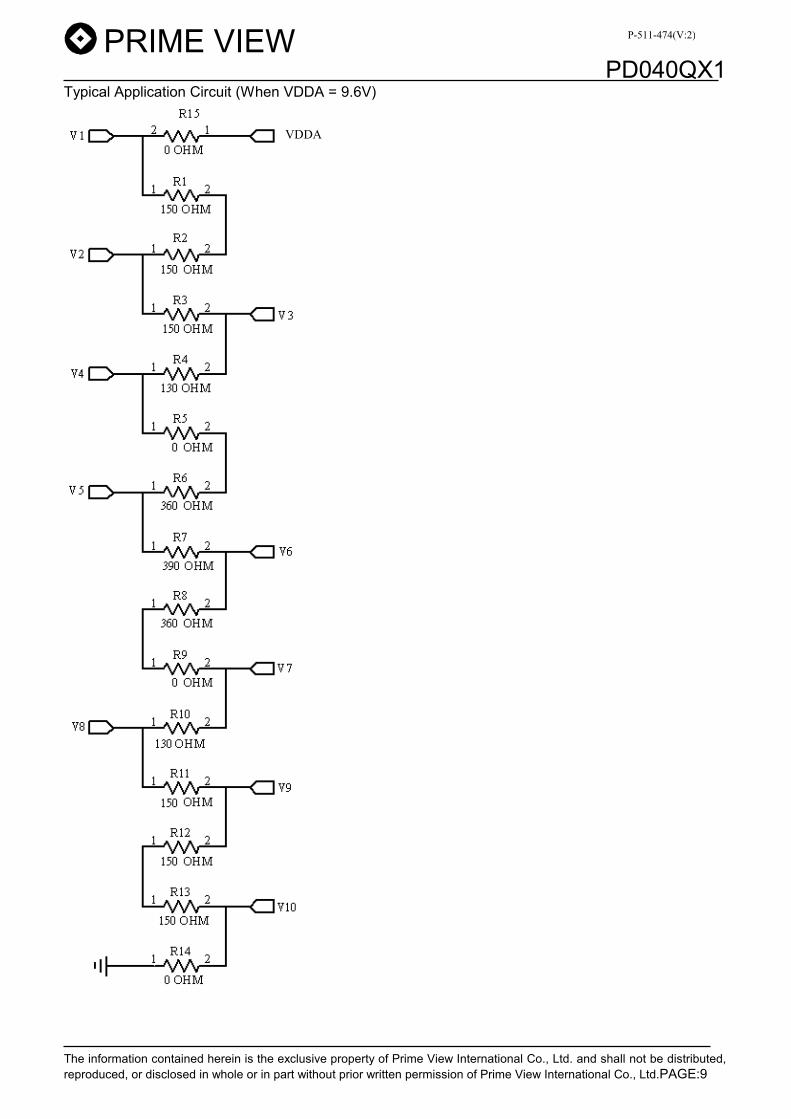
Pin No. Symbol Function Remark 1 VLED Voltage for LED 2 GLED2 LED ground 3 GLED2 LED ground 4 GND Digital ground 5 VCOM Voltage for common electrode Note 5-7 6 VSET Externally/Internally gamma voltage setup Note 5-11 7 VDDA Analog power supply for source driver Note 5-2 8 V10 Gamma correction voltage 10 9 V9 Gamma correction voltage 9
10 V8 Gamma correction voltage 8 11 V7 Gamma correction voltage 7 12 V6 Gamma correction voltage 6 13 V5 Gamma correction voltage 5 14 V4 Gamma correction voltage 4 15 V3 Gamma correction voltage 3 16 V2 Gamma correction voltage 2 17 V1 Gamma correction voltage 1 18 VSSA Analog ground for source drive 19 L/R Left/Right control for source driver Note 5-12 20 U/D Up/Down control for gate driver Note 5-12 21 GND Digital ground 22 VCC1 Digital power supply for source driver Note 5-6 23 RESETB Hardware global reset 24 SPDA Serial port data input/output 25 SPCK Serial port clock 26 SPENA Serial port data enable signal 27 DEN Input data enable control Note 5-5 28 HS Horizontal sync input Note 5-3 29 VS Vertical sync input Note 5-4 30 CLK Clock signal. Latching data at the rising edge
P-511-474(V:2)

PD040QX1
The information contained herein is the exclusive property of Prime View International Co., Ltd. and shall not be distributed, reproduced, or disclosed in whole or in part without prior written permission of Prime View International Co., Ltd.PAGE:8
Note 5-1 : Digital data input. DX0 is LSB and DX7 is MSB. If parallel RGB input mode is used, D0X, D1X, and D2X indicate R, G and B data in turn. If serial RGB or CCIR601/656 input mode is selected, only D07~D00 are used, and others short to GND.
Note 5-2 : VDDA Typ. = 9.6V
Note 5-3 : Horizontal sync input in digital RGB mode and CCIR601 mode. ( Short to GND if not used )
Note 5-4 : Vertical sync input in digital RGB mode and CCIR601 mode. ( Short to GND if not used )
Note 5-5 : The SYNC(HS+VS) Mode and DEN mode are supported. If DEN signal is fixed low, SYNC Mode is used. Otherwise , DEN mode is used.
Note 5-6 : VCC1 Typ. = 3.3V
Note 5-7 : VCOM Typ.Ј3.68V
Note 5-8 : VEE Typ. = -8V
Note 5-9 : VCC2 Typ.Ј3.3V
Note 5-10 : VGG Typ. =17V
Note 5-11 :If.VSET=”H”,the gamma correction voltage generated externally.
Note 5-12 : The definition of L/R , U/D
U/ D CN2( PIN 20)= Low L/ R CN2( PIN 19)=High
U/ D CN2( PIN 20)= High L/ R CN2( PIN 19)=Low
P-511-474(V:2)
PD040QX1
The information contained herein is the exclusive property of Prime View International Co., Ltd. and shall not be distributed, reproduced, or disclosed in whole or in part without prior written permission of Prime View International Co., Ltd.PAGE:9
Typical Application Circuit (When VDDA = 9.6V)
VDDA
P-511-474(V:2)

PD040QX1
The information contained herein is the exclusive property of Prime View International Co., Ltd. and shall not be distributed, reproduced, or disclosed in whole or in part without prior written permission of Prime View International Co., Ltd.PAGE:10
6. Absolute Maximum Ratings: GND=0V, Ta=25к
Parameters Symbol MIN. MAX. Unit Remark VCC2 -0.3 6.0 V VCC1 -0.3 7.0 V VDDA -0.3 13.5 V VGG -0.3 40.0 V
VGG-VEE -0.3 40.0 V
Supply Voltage
VEE -20 0.3 V 7. Electrical Characteristics 7-1) Recommended Operating Conditions:
VSSA=GND=0V, Ta=25к Item Symbol Min. Typ. Max. Unit Remark
VCC1 2.7 3.3 3.6 V Note 7-1 Supply Voltage for Source Driver VDDA 6.5 9.6 13.5 V VGG - 17 - V VEE - -8 - V Supply Voltage for Gate Driver
VCC2 2.7 3.3 3.6 V VCOM Voltage VCOM - 4.1 - V
VIH 0.7 VCC - VCC V Digital Input Voltage
VIL 0 - 0.3 VCC V
Note 7-1 : To test the current dissipation of VCC, using the “color bars” testing pattern shown as below.
1 2 3 4 5 6 7 8
1. White2. Yellow3. Cyan4. Green5. Magenta6. Red7. Blue8. Black
IDD current dissipation testing pattern
7-2) Recommended Driving Condition for Back Light Ta=25к
Parameter Symbol Min. Typ. Max. Unit Remark Supply voltage of LED backlight VLED - - (14) V Note 7-2 Supply current of LED backlight ILED - 20 - mA Note 7-3 Backlight Power Consumption PLED - - 560 mW Note 7-2Ε7-4 Note 7-2 : ILED= 20mA,constant current Note 7-3 : The LED driving condition is defined for each LED module. (4 LED Serial) Input current = 20mA * 2 = 40mA Note 7-4 : PLED = VLED-1 * ILED-1 + VLED-2* ILED-2
Cathode
VLED-1
VLED-2
Anode
P-511-474(V:2)

PD040QX1
The information contained herein is the exclusive property of Prime View International Co., Ltd. and shall not be distributed, reproduced, or disclosed in whole or in part without prior written permission of Prime View International Co., Ltd.PAGE:11
7-3) Power Consumption
Parameter Symbol Condition Typ. Max. Unit Remark Supply Current for Gate Driver (Hi level) IGG VGG= 17V 0.1 0.3 mA
Supply Current for Gate Driver (Low level) IEE VEE= -8V 0.1 0.3 mA
Supply Current for Gate Driver (Digital) ICC2 VCC2= 3.3V 0.1 0.2 mA
Supply Current for Source Driver (Digital) ICC1 VCC1= 3.3V 0.9 1.8 mA
Supply Current for Source Driver (Analog) IDD VDD= 9.6V 4.6 9.2 mA
LCD Panel Power Consumption - - 49.96 102.42 mW Note 7-5
Backlight LED Power Consumption PLED - 512 560 mW Note 7-6
Total Power Consumption - - 561.96 662.42 mW Note 7-5: The power consumption for backlight is not included.
Note 7-6: Back light power consumption is calculated by ILVL. 8. Pixel Arrangement
R G B R G B R G B R G B
R G B R G B
R G B
R G B R G B R G B R G B
R G B R G B
R G B
3 rd Line
2 nd Line
1 st Line
240 th Line
239 thLine
238 th Line
R G B
R G B
R G B
R G B 1 st Pixel
320th pixel
1 Pixel = R G B
P-511-474(V:2)

PD040QX1
The information contained herein is the exclusive property of Prime View International Co., Ltd. and shall not be distributed, reproduced, or disclosed in whole or in part without prior written permission of Prime View International Co., Ltd.PAGE:12
9. Display Color and Gray Scale Reference
p����Gj����Gk���p����Gj����Gk���p����Gj����Gk���p����Gj����Gk���GGGG
y��G n����G i���G
G G
j����G
G G y^y^y^y^GGGGy]y]y]y]GGGGy\y\y\y\GGGGy[y[y[y[GGGGyZyZyZyZGGGGyYyYyYyYGGGGyXyXyXyXGGGGyWyWyWyWGGGGn^n^n^n^GGGGn]n]n]n]GGGGn\n\n\n\GGGGn[n[n[n[GGGGnZnZnZnZGGGGnYnYnYnYGGGGnXnXnXnXGGGG nWnWnWnWGGGG i^i^i^i^GGGGi]i]i]i]GGGGi\i\i\i\GGGGi[i[i[i[GGGGiZiZiZiZGGGGiYiYiYiYGGGGiXiXiXiXGGGGiWiWiWiWGGGG
i����G WG WG WG WG WG WG WG WG WG WG WG WG WG WG WG WG WG WG WG WG WG WG WG WG
y��G XG XG XG XG XG XG XG XG WG WG WG WG WG WG WG WG WG WG WG WG WG WG WG WG
n����G WG WG WG WG WG WG WG WG XG XG XG XG XG XG XG XG WG WG WG WG WG WG WG WG
i���G WG WG WG WG WG WG WG WG WG WG WG WG WG WG WG WG XG XG XG XG XG XG XG XG
j ��G WG WG WG WG WG WG WG WG XG XG XG XG XG XG XG XG XG XG XG XG XG XG XG XG
t����� XG XG XG XG XG XG XG XG WG WG WG WG WG WG WG WG XG XG XG XG XG XG XG XG
������G XG XG XG XG XG XG XG XG XG XG XG XG XG XG XG XG WG WG WG WG WG WG WG WG
G
G
G G
i����G
j�����G
G G
G G
G G~����G XG XG XG XG XG XG XG XG XG XG XG XG XG XG XG XG XG XG XG XG XG XG XG XG
y��G WG WG WG WG WG WG WG WG WG WG WG WG WG WG WG WG WG WG WG WG WG WG WG WG
y��G WG WG WG WG WG WG WG XG WG WG WG WG WG WG WG WG WG WG WG WG WG WG WG WG
y��G WG WG WG WG WG WG XG WG WG WG WG WG WG WG WG WG WG WG WG WG WG WG WG WG
k�����G G G G G G G G G G G G G G G G G G G G G G G G G
˨ G ˨ G ˨ G ˨ G ˨ G ˨ G ˨ G ˨ G ˨ G ˨ G ˨ G ˨ G ˨ G ˨ G ˨ G ˨ G ˨ G ˨ G ˨ G ˨ G ˨ G ˨ G ˨ G ˨ G ˨ G
i������ G G G G G G G G G G G G G G G G G G G G G G G G
y��G XG XG XG XG XG XG WG XG WG WG WG WG WG WG WG WG WG WG WG WG WG WG WG WG
y��G XG XG XG XG XG XG XG WG WG WG WG WG WG WG WG WG WG WG WG WG WG WG WG WG
G G
G G
G G
G G
y��G
G G
G G
G G
G Gy��G XG XG XG XG XG XG XG XG WG WG WG WG WG WG WG WG WG WG WG WG WG WG WG WG
n����G WG WG WG WG WG WG WG WG WG WG WG WG WG WG WG WG WG WG WG WG WG WG WG WG
n����G WG WG WG WG WG WG WG WG WG WG WG WG WG WG WG XG WG WG WG WG WG WG WG WG
n����G WG WG WG WG WG WG WG WG WG WG WG WG WG WG XG WG WG WG WG WG WG WG WG WG
k�����G G G G G G G G G G G G G G G G G G G G G G G G G
˨ G ˨ G ˨ G ˨ G ˨ G ˨ G ˨ G ˨ G ˨ G ˨ G ˨ G ˨ G ˨ G ˨ G ˨ G ˨ G ˨ G ˨ G ˨ G ˨ G ˨ G ˨ G ˨ G ˨ G ˨ G
i������ G G G G G G G G G G G G G G G G G G G G G G G G G
n����G WG WG WG WG WG WG WG WG XG XG XG XG XG XG WG XG WG WG WG WG WG WG WG WG
n����G WG WG WG WG WG WG WG WG XG XG XG XG XG XG XG WG WG WG WG WG WG WG WG WG
G G
G G
G G
G G
n����G
G G
G G
G G
G Gn����G WG WG WG WG WG WG WG WG XG XG XG XG XG XG XG XG WG WG WG WG WG WG WG WG
i���G WG WG WG WG WG WG WG WG WG WG WG WG WG WG WG WG WG WG WG WG WG WG WG WG
i���G WG WG WG WG WG WG WG WG WG WG WG WG WG WG WG WG WG WG WG WG WG WG WG XG
i���G WG WG WG WG WG WG WG WG WG WG WG WG WG WG WG WG WG WG WG WG WG WG XG WG
k�����G G G G G G G G G G G G G G G G G G G G G G G G G
˨ G ˨ G ˨ G ˨ G ˨ G ˨ G ˨ G ˨ G ˨ G ˨ G ˨ G ˨ G ˨ G ˨ G ˨ G ˨ G ˨ G ˨ G ˨ G ˨ G ˨ G ˨ G ˨ G ˨ G ˨ G
i������ G G G G G G G G G G G G G G G G G G G G G G G G
i���G WG WG WG WG WG WG WG WG WG WG WG WG WG WG WG WG XG XG XG XG XG XG WG XG
i���G WG WG WG WG WG WG WG WG WG WG WG WG WG WG WG WG XG XG XG XG XG XG XG WG
G G
G G
G G
G G
i���G
G G
G G
G G
G Gi���G WG WG WG WG WG WG WG WG WG WG WG WG WG WG WG WG XG XG XG XG XG XG XG XG
P-511-474(V:2)
PD040QX1
The information contained herein is the exclusive property of Prime View International Co., Ltd. and shall not be distributed, reproduced, or disclosed in whole or in part without prior written permission of Prime View International Co., Ltd.PAGE:13
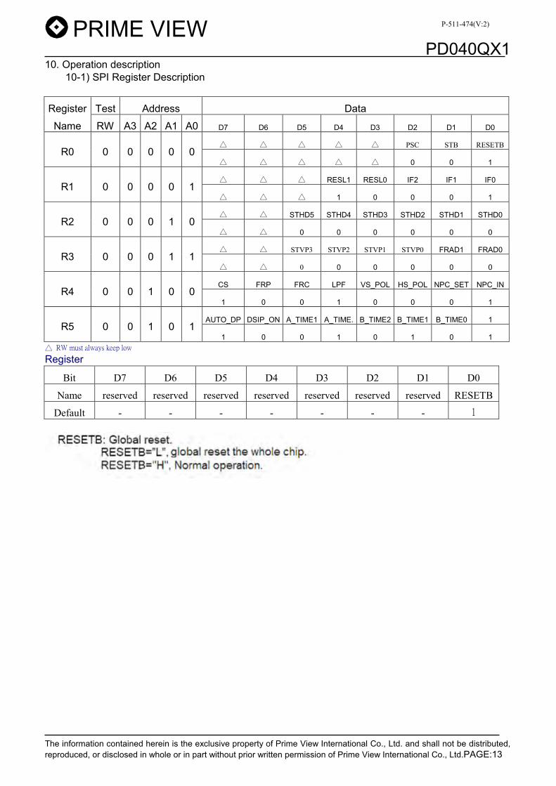
10. Operation description 10-1) SPI Register Description
Register Test Address Data
Name RW A3 A2 A1 A0 D7 D6 D5 D4 D3 D2 D1 D0
Ϧʳ Ϧʳ Ϧʳ Ϧʳ Ϧʳ PSC STB RESETB R0 0 0 0 0 0
Ϧʳ Ϧʳ Ϧʳ Ϧʳ Ϧʳ 0 0 1
Ϧʳ Ϧʳ Ϧʳ RESL1 RESL0 IF2 IF1 IF0 R1 0 0 0 0 1
Ϧʳ Ϧʳ Ϧʳ 1 0 0 0 1
Ϧʳ Ϧʳ STHD5 STHD4 STHD3 STHD2 STHD1 STHD0 R2 0 0 0 1 0
Ϧʳ Ϧʳ 0 0 0 0 0 0
Ϧʳ Ϧʳ STVP3 STVP2 STVP1 STVP0 FRAD1 FRAD0 R3 0 0 0 1 1
Ϧʳ Ϧʳ 0 0 0 0 0 0
CS FRP FRC LPF VS_POL HS_POL NPC_SET NPC_IN R4 0 0 1 0 0
1 0 0 1 0 0 0 1
AUTO_DP DSIP_ON A_TIME1 A_TIME. B_TIME2 B_TIME1 B_TIME0 1 R5 0 0 1 0 1
1 0 0 1 0 1 0 1 Ϧʳ ˥˪ʳʳ˴˿˴ʳ˾˸˸ʳ˿ Register
Bit D7 D6 D5 D4 D3 D2 D1 D0 Name reserved reserved reserved reserved reserved reserved reserved RESETB
Default - - - - - - - ˄ʳ
P-511-474(V:2)

PD040QX1
The information contained herein is the exclusive property of Prime View International Co., Ltd. and shall not be distributed, reproduced, or disclosed in whole or in part without prior written permission of Prime View International Co., Ltd.PAGE:14
Register R1 Bit D7 D6 D5 D4 D3 D2 D1 D0
Name reserved reserved reserved RESL1 RESL0 IF2 IF1 IF0 Default - - - 1 0 0 0 ˄ʳ
Register R1 setting RESL [1:0]:Display resolution selection
RESL1 RESL0 Resolution ˃ʳ ˃ʳ 320×RGB×240 ˃ʳ ˄ʳ reserved ˄ʳ ˃ʳ reserved ˄ʳ ˄ʳ reserved
Display resolution selection
IF[2:0]:Data input mode selection
IF2 IF1 IF0 Data input format operating freq ˃ʳ ˃ʳ ˃ʳ reserved reserved ˃ʳ ˃ʳ ˄ʳ 24-bis parallel RGB 25.175MHz(MAX) ˃ʳ ˄ʳ ˃ʳ reserved reserved ˃ʳ ˄ʳ ˄ʳ reserved reserved ˄ʳ ˃ʳ ˃ʳ reserved reserved ˄ʳ ˃ʳ ˄ʳ reserved reserved ˄ʳ ˄ʳ ˃ʳ reserved reserved ˄ʳ ˄ʳ ˄ʳ reserved reserved
Data input mode selection Register R2
Bit D7 D6 D5 D4 D3 D2 D1 D0 Name reserved reserved STHD5 STHD4 STHD3 STHD2 STHD1 STHD0
Default - - ˃ʳ ˃ʳ ˃ʳ ˃ʳ ˃ʳ ˃ʳ
Register R2 setting
P-511-474(V:2)

PD040QX1
The information contained herein is the exclusive property of Prime View International Co., Ltd. and shall not be distributed, reproduced, or disclosed in whole or in part without prior written permission of Prime View International Co., Ltd.PAGE:15
STHD[5:0]:adjust start pulse position by dot ʳ ʳ ʳ ʳ
STHD5 STHD4 STHD3 STHD2 STHD1 STHD0 STH position
sdjust Unit
˃ʳ ˃ʳ ˃ʳ ˃ʳ ˃ʳ ˃ʳ ˃ʳ TCPH ˃ʳ ˃ʳ ˃ʳ ˃ʳ ˃ʳ ˄ʳ +1 TCPH ˃ʳ ˃ʳ ˃ʳ ˃ʳ ˄ʳ ˃ʳ +2 TCPH ˃ʳ ˃ʳ ˃ʳ ˃ʳ ˄ʳ ˄ʳ +3 TCPH ˃ʳ ˃ʳ ˃ʳ ˄ʳ ˃ʳ ˃ʳ +4 TCPH ˃ʳ ˃ʳ ˃ʳ ˄ʳ ˃ʳ ˄ʳ +5 TCPH ˃ʳ ˃ʳ ˃ʳ ˄ʳ ˄ʳ ˃ʳ +6 TCPH ˃ʳ ˃ʳ ˃ʳ ˄ʳ ˄ʳ ˄ʳ +7 TCPH
ʳ ʳ
˃ʳ ˄ʳ ˄ʳ ˃ʳ ˃ʳ ˃ʳ +24 TCPH ˃ʳ ˄ʳ ˄ʳ ˃ʳ ˃ʳ ˄ʳ +25 TCPH ˃ʳ ˄ʳ ˄ʳ ˃ʳ ˄ʳ ˃ʳ +26 TCPH ˃ʳ ˄ʳ ˄ʳ ˃ʳ ˄ʳ ˄ʳ +27 TCPH ˃ʳ ˄ʳ ˄ʳ ˄ʳ ˃ʳ ˃ʳ +28 TCPH ˃ʳ ˄ʳ ˄ʳ ˄ʳ ˃ʳ ˄ʳ +29 TCPH ˃ʳ ˄ʳ ˄ʳ ˄ʳ ˄ʳ ˃ʳ +30 TCPH ˃ʳ ˄ʳ ˄ʳ ˄ʳ ˄ʳ ˄ʳ +31 TCPH ˄ʳ ˃ʳ ˃ʳ ˃ʳ ˃ʳ ˃ʳ -1 TCPH ˄ʳ ˃ʳ ˃ʳ ˃ʳ ˃ʳ ˄ʳ -2 TCPH ˄ʳ ˃ʳ ˃ʳ ˃ʳ ˄ʳ ˃ʳ -3 TCPH ˄ʳ ˃ʳ ˃ʳ ˃ʳ ˄ʳ ˄ʳ -4 TCPH ˄ʳ ˃ʳ ˃ʳ ˄ʳ ˃ʳ ˃ʳ -5 TCPH ˄ʳ ˃ʳ ˃ʳ ˄ʳ ˃ʳ ˄ʳ -6 TCPH ˄ʳ ˃ʳ ˃ʳ ˄ʳ ˄ʳ ˃ʳ -7 TCPH ˄ʳ ˃ʳ ˃ʳ ˄ʳ ˄ʳ ˄ʳ -8 TCPH
ʳ ʳ
˃ʳ ˃ʳ ˃ʳ ˃ʳ ˃ʳ ˃ʳ -25 TCPH ˃ʳ ˃ʳ ˃ʳ ˃ʳ ˃ʳ ˄ʳ -26 TCPH ˃ʳ ˃ʳ ˃ʳ ˃ʳ ˄ʳ ˃ʳ -27 TCPH ˃ʳ ˃ʳ ˃ʳ ˃ʳ ˄ʳ ˄ʳ -28 TCPH ˃ʳ ˃ʳ ˃ʳ ˄ʳ ˃ʳ ˃ʳ -29 TCPH ˃ʳ ˃ʳ ˃ʳ ˄ʳ ˃ʳ ˄ʳ -30 TCPH ˃ʳ ˃ʳ ˃ʳ ˄ʳ ˄ʳ ˃ʳ -31 TCPH ˃ʳ ˃ʳ ˃ʳ ˄ʳ ˄ʳ ˄ʳ -32 TCPH
P-511-474(V:2)

PD040QX1
The information contained herein is the exclusive property of Prime View International Co., Ltd. and shall not be distributed, reproduced, or disclosed in whole or in part without prior written permission of Prime View International Co., Ltd.PAGE:16
Register R3
Bit D7 D6 D5 D4 D3 D2 D1 D0 Name reserved reserved STVP3 STVP2 STVP1 STVP0 FRAD1 FRAD0
Default - - 0 0 0 0 0 ˃ʳRegister R3 setting
STVP3 STVP2 STVP1 STVP0 STV position adjust Unit ˃ʳ ˃ʳ ˃ʳ ˃ʳ ˃ʳ TH ˃ʳ ˃ʳ ˃ʳ ˄ʳ +1 TH ˃ʳ ˃ʳ ˄ʳ ˃ʳ +2 TH ˃ʳ ˃ʳ ˄ʳ ˄ʳ +3 TH ˃ʳ ˄ʳ ˃ʳ ˃ʳ +4 TH ˃ʳ ˄ʳ ˃ʳ ˄ʳ +5 TH ˃ʳ ˄ʳ ˄ʳ ˃ʳ +6 TH ˃ʳ ˄ʳ ˄ʳ ˄ʳ +7 TH ˄ʳ ˃ʳ ˃ʳ ˃ʳ -1 TH ˄ʳ ˃ʳ ˃ʳ ˄ʳ -2 TH ˄ʳ ˃ʳ ˄ʳ ˃ʳ -3 TH ˄ʳ ˃ʳ ˄ʳ ˄ʳ -4 TH ˄ʳ ˄ʳ ˃ʳ ˃ʳ -5 TH ˄ʳ ˄ʳ ˃ʳ ˄ʳ -6 TH ˄ʳ ˄ʳ ˄ʳ ˃ʳ -7 TH ˄ʳ ˄ʳ ˄ʳ ˄ʳ -8 TH
Adjust first line position by line
FRAD[1:0]:Odd frame or Even frame advance control FRAD1 FRAD0 Advance Frame Notes ˃ʳ ˃ʳ reserved reserved ˃ʳ ˄ʳ reserved reserved ˄ʳ ˃ʳ Even Frame Odd frame Tstv=STVP setting + 1H ˄ʳ ˄ʳ Reserve Reserve
Odd frame or Even frame Advance control
P-511-474(V:2)

PD040QX1
The information contained herein is the exclusive property of Prime View International Co., Ltd. and shall not be distributed, reproduced, or disclosed in whole or in part without prior written permission of Prime View International Co., Ltd.PAGE:17
Register R4 ʳ ʳ ʳ ʳ ʳ ʳ ʳ
Bit D7 D6 D5 D4 D3 D2 D1 D0 Name reserved reserved reserved reserved VS_POL HS_POL NPC_SET NPC_IN
Default - - - - 0 0 0 ˄ʳRegister R4 setting
P-511-474(V:2)

PD040QX1
The information contained herein is the exclusive property of Prime View International Co., Ltd. and shall not be distributed, reproduced, or disclosed in whole or in part without prior written permission of Prime View International Co., Ltd.PAGE:18
Register R5 ʳ ʳ ʳ ʳ ʳ ʳ ʳ
Bit D7 D6 D5 D4 D3 D2 D1 D0 Name AUTO_DP SISP_ON A_TIME1 A_TIME0 B_TIME2 B_TIME2 B_TIME0 reserved
Default 1 0 0 1 0 1 0 - Register R5 setting
P-511-474(V:2)

PD040QX1
The information contained herein is the exclusive property of Prime View International Co., Ltd. and shall not be distributed, reproduced, or disclosed in whole or in part without prior written permission of Prime View International Co., Ltd.PAGE:19
10-2) Power ON/OFF sequence
10-3) Power ON Control
P-511-474(V:2)

PD040QX1
The information contained herein is the exclusive property of Prime View International Co., Ltd. and shall not be distributed, reproduced, or disclosed in whole or in part without prior written permission of Prime View International Co., Ltd.PAGE:20
10-4) Standby ON/OFF Control
10-5) Reset when power on
P-511-474(V:2)

PD040QX1
The information contained herein is the exclusive property of Prime View International Co., Ltd. and shall not be distributed, reproduced, or disclosed in whole or in part without prior written permission of Prime View International Co., Ltd.PAGE:21
11.AC Characteristics 11-1) SPI timing characteristics
11-2) Digital Parallel RGB interface
P-511-474(V:2)

PD040QX1
The information contained herein is the exclusive property of Prime View International Co., Ltd. and shall not be distributed, reproduced, or disclosed in whole or in part without prior written permission of Prime View International Co., Ltd.PAGE:22
12. Waveform Timing Controller Timing Chart
12-1) SPI timing
12-2) Clock and Data input waveforms
P-511-474(V:2)

PD040QX1
The information contained herein is the exclusive property of Prime View International Co., Ltd. and shall not be distributed, reproduced, or disclosed in whole or in part without prior written permission of Prime View International Co., Ltd.PAGE:23
12-3) Data input format for RGB Mode
P-511-474(V:2)

PD040QX1
The information contained herein is the exclusive property of Prime View International Co., Ltd. and shall not be distributed, reproduced, or disclosed in whole or in part without prior written permission of Prime View International Co., Ltd.PAGE:24
P-511-474(V:2)

PD040QX1
The information contained herein is the exclusive property of Prime View International Co., Ltd. and shall not be distributed, reproduced, or disclosed in whole or in part without prior written permission of Prime View International Co., Ltd.PAGE:25
12-4) The HS & VS timing of the ODD/EVEN field
.
P-511-474(V:2)

PD040QX1
The information contained herein is the exclusive property of Prime View International Co., Ltd. and shall not be distributed, reproduced, or disclosed in whole or in part without prior written permission of Prime View International Co., Ltd.PAGE:26
13.Power On Sequence
VDD
3.0V
0.3V
3.0V
t1 t2 t3
Signal*3
1. 0Іt1Љ20ms 2. 0Іt2Љ50ms 3. 0Іt3Љ1s 14. Optical Characteristics
14-1) Specification: Ta = 25к
Parameter Symbol Condition MIN. TYP. MAX. Unit Remarks Horizontal Ӱ21, Ӱ22 75 80 --- deg
Ӱ12 45 50 --- deg Viewing Angle Vertical
Ӱ11 CRЊ10
55 60 --- deg Note 14-1
Contrast Ratio CR At optimized Viewing angle 200 400 --- Note 14-2
Luminance L Ӱ=0 300 350 --- cd/ф x Ӱ=0 0.26 0.30 0.34 White Chromaticity y Ӱ=0 0.29 0.33 0.37
Rise Tr --- 15 30 ms Response time Fall Tf
Ӱ=0 --- 25 50 ms Note 14-3
Uniformity U - 75 80 --- % Note 14-5 Cross Talk Ratio CTK - --- --- 3.5 % Note 14-6
LED Life Time +25к 20000 30000 --- hrs Note 14-4
10ms 10ms
Back Light ON OFF OFF
P-511-474(V:2)

PD040QX1
The information contained herein is the exclusive property of Prime View International Co., Ltd. and shall not be distributed, reproduced, or disclosed in whole or in part without prior written permission of Prime View International Co., Ltd.PAGE:27
Note 14-1 : The definitions of viewing angles
Luminance when Testing point is White Note 14-2 : CR Ј Luminance when Testing point is Black
Contrast Ratio is measured in optimum common electrode voltage.
Note 14-3 : The definition of response time :
100%90%
10%
0%
White White
Brightness
Black
Tr Tf
Note 14-4 : The “LED Life time “ is defined as the module brightness decrease to 50% original Brightness
that the ambient temperature is 25к and ILED =20mA
P-511-474(V:2)

PD040QX1
The information contained herein is the exclusive property of Prime View International Co., Ltd. and shall not be distributed, reproduced, or disclosed in whole or in part without prior written permission of Prime View International Co., Ltd.PAGE:28
Note 14-5: The uniformity of LCD is defined as The Minimum Brightness of the 9 testing Points U = The Maximum Brightness of the 9 testing Points
Luminance meter : BM-5A or BM-7 fast(TOPCON) Measurement distance : 500 mm +/- 50 mm Ambient illumination : < 1 Lux Measuring direction : Perpendicular to the surface of module The test pattern is white (Gray Level 63).
1/6
1/6
2/6
2/6
1/6 1/62/6 2/6
YA-YB Note 14-6: Cross Talk (CTK) = YA
100%
YA: Brightness of Pattern A YB: Brightness of Pattern B Luminance meter : BM 5A (TOPCON) Measurement distance : 500 mm +/- 50 mm Ambient illumination : < 1 Lux Measuring direction : Perpendicular to the surface of module
Pattern A(Gray Level 31)
Pattern B(Gray Level 31, central
black box exclusive)
: Measuring Point (A and B are at the same point.)
YAYB
1/3
1/3
1/3
1/3 1/3 1/3Black
(Gray Level 0)
P-511-474(V:2)

PD040QX1
The information contained herein is the exclusive property of Prime View International Co., Ltd. and shall not be distributed, reproduced, or disclosed in whole or in part without prior written permission of Prime View International Co., Ltd.PAGE:29
15. Handling Cautions 15-1) Mounting of module
A) Please power off the module when you connect the input/output connector. B) Polarizer which is made of soft material and susceptible to flaw must be handled carefully. C)Protective film (Laminator) is applied on surface to protect it against scratches and dirt. D)Please following the tear off direction as figure15-1 to remove the protective film as slowly
as possible, so that electrostatic charge can be minimized. 15-2) Precautions in mounting
A) When metal part of the TFT-LCD module (shielding lid and rear case) is soiled, wipe it with soft dry cloth.
B) Wipe off water drops or finger grease immediately. Long contact with water may cause discoloration or spots.
C) TFT-LCD module uses glass which breaks or cracks easily if dropped or bumped on hard surface. Please handle with care.
D) Since CMOS LSI is used in the module. So take care of static electricity and earth yourself when handling.
15-3) Adjusting module A) Adjusting volumes on the rear face of the module have been set optimally before shipment. B) Therefore, do not change any adjusted values. If adjusted values are changed, the
specifications described may not be satisfied. 15-4) Others
A) Do not expose the module to direct sunlight or intensive ultraviolet rays for many hours. B) Store the module at a room temperature place. C) The voltage of beginning electric discharge may over the normal voltage because of
leakage current from approach conductor by to draw lump read lead line around. D) If LCD panel breaks, it is possibly that the liquid crystal escapes from the panel.
Avoid putting it into eyes or mouth. When liquid crystal sticks on hands, clothes or feet. Wash it out immediately with soap.
E) Observe all other precautionary requirements in handling general electronic components. F) Please adjust the voltage of common electrode as material of attachment by 1 module.
15-5) Polarizer mark The polarizer mark is to describe the direction of view angle film how to mach up with the rubbing direction.
Figure 15 -1 the way to peel off protective film
P-511-474(V:2)

PD040QX1
The information contained herein is the exclusive property of Prime View International Co., Ltd. and shall not be distributed, reproduced, or disclosed in whole or in part without prior written permission of Prime View International Co., Ltd.PAGE:30
16. Reliability Test
No Test Item Test Condition 1 High Temperature Storage Test Ta = +80к, 240 hrs 2 Low Temperature Storage Test Ta = -40к, 240 hrs 3 High Temperature Operation Test Ta = +80к, 240 hrs 4 Low Temperature Operation Test Ta = -30к, 240 hrs
5 High Temperature & High Humidity Operation Test Ta = +60к, 90%RH, 240 hrs
6 Thermal Cycling Test (non-operating)
-30кШ+80к, 200 Cycles, 30 min 30 min
7 Vibration Test (non-operating)
Frequency:10~55HZ Amplitude: 1.5mm
Sweep time:11 mins Test Period:6 Cycles for each direction of X,Y,Z
8 Shock Test (non-operating)
100G, 6ms Direction : X, Y, Z
Cycle : 3 times
9 Electrostatic Discharge Test (non-operating)
200pF, 0Ө 200V 1 time / each terminal
Ta: ambient temperature Note : The protective film must be removed before temperature test.
[Criteria] In the standard conditions, there is not display function NG issue occurred. (including : line defect ,no
image).All the cosmetic specification is judged before the reliability stress.
P-511-474(V:2)

PD040QX1
The information contained herein is the exclusive property of Prime View International Co., Ltd. and shall not be distributed, reproduced, or disclosed in whole or in part without prior written permission of Prime View International Co., Ltd.PAGE:31
17. Block Diagram
˗˖ˀ ˗˖ʳ˖˸˸
˚˴˴˚˸˸˴
˩˶˚˸˸˴
˙ˣ˖
˦˶˸˗˼˸˜˖
˚˴˸ʳ˗˼˸ʳ˜˖
ˇʵˤ˩˚˔˧˙˧ ˀ˟˖˗ʳˣ˴˸˿
˩˼˷˸
˖˿
˩˗˗˅
˚˴˴
˩˶
˩˚˚ʳ˂ʳ˩˘˘
˨˸
˼˺˴˿ʳ
˼
Vcc1
Vcc 2
Vcc
Vcc
P-511-474(V:2)

PD040QX1
The information contained herein is the exclusive property of Prime View International Co., Ltd. and shall not be distributed, reproduced, or disclosed in whole or in part without prior written permission of Prime View International Co., Ltd.PAGE:32
18. Packing
P-511-474(V:2)


![標準品 LPM027M128C specification ver02 20170731 · 2017-10-18 · rite black dat ark] and VDDA s and VDDA s Product N ON/OFF SE rising time. (D initialization 1 for internal lat](https://img.pdfslide.us/doc/110x75/5e421e2a4bfc07225b762667/-lpm027m128c-specification-ver02-20170731-2017-10-18-rite-black-dat-ark.jpg)