Embed Size (px)
Citation preview
S.No DOCUMENT DESCRIPTIONANNEXURE
REFERENCE
NUMBER OF
PAGES IN EACH
DOCUMENT
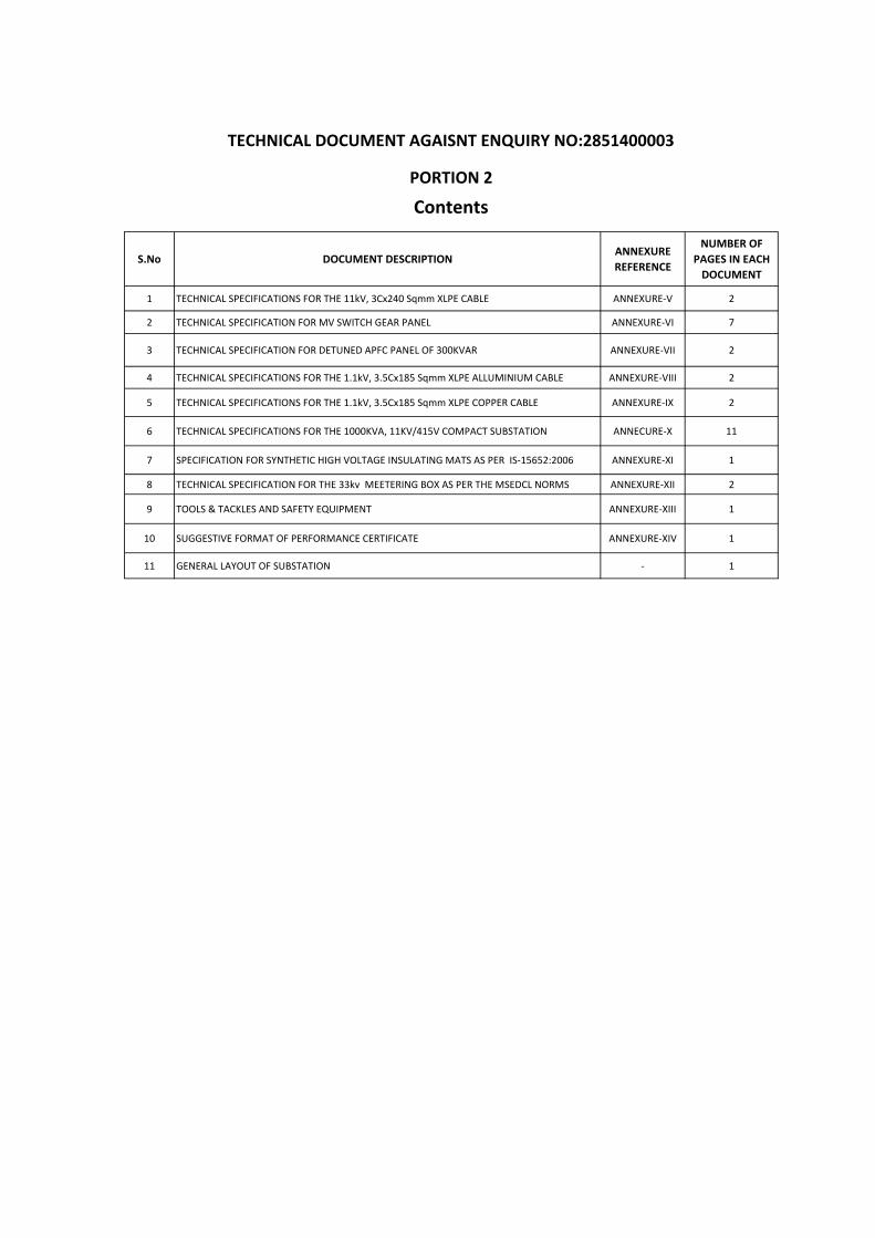
1 TECHNICAL SPECIFICATIONS FOR THE 11kV, 3Cx240 Sqmm XLPE CABLE ANNEXURE‐V 2
2 TECHNICAL SPECIFICATION FOR MV SWITCH GEAR PANEL ANNEXURE‐VI 7
3 TECHNICAL SPECIFICATION FOR DETUNED APFC PANEL OF 300KVAR ANNEXURE‐VII 2
4 TECHNICAL SPECIFICATIONS FOR THE 1.1kV, 3.5Cx185 Sqmm XLPE ALLUMINIUM CABLE ANNEXURE‐VIII 2
5 TECHNICAL SPECIFICATIONS FOR THE 1.1kV, 3.5Cx185 Sqmm XLPE COPPER CABLE ANNEXURE‐IX 2
6 TECHNICAL SPECIFICATIONS FOR THE 1000KVA, 11KV/415V COMPACT SUBSTATION ANNECURE‐X 11
7 SPECIFICATION FOR SYNTHETIC HIGH VOLTAGE INSULATING MATS AS PER IS‐15652:2006 ANNEXURE‐XI 1
8 TECHNICAL SPECIFICATION FOR THE 33kv MEETERING BOX AS PER THE MSEDCL NORMS ANNEXURE‐XII 2
9 TOOLS & TACKLES AND SAFETY EQUIPMENT ANNEXURE‐XIII 1
10 SUGGESTIVE FORMAT OF PERFORMANCE CERTIFICATE ANNEXURE‐XIV 1
11 GENERAL LAYOUT OF SUBSTATION ‐ 1
TECHNICAL DOCUMENT AGAISNT ENQUIRY NO:2851400003
Contents
PORTION 2
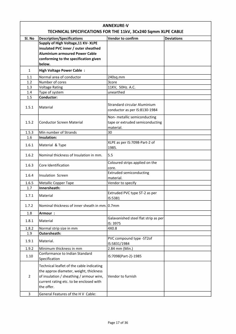
Sl. No Description/Specifications Vendor to confirm DeviationsSupply of High Voltage,11 KV‐ XLPE
insulated PVC inner / outer sheathed
Aluminium armoured Power Cable
conforming to the specification given
below.
1 High Voltage Power Cable :
1.1 Normal area of conductor 240sq.mm
1.2 Number of cores 3core
1.3 Voltage Rating 11KV, 50Hz. A.C.
1.4 Type of system unearthed
1.5 Conductor:
1.5.1 MaterialStrandard circular Aluminium
conductor as per IS:8130‐1984
1.5.2 Conductor Screen Material
Non‐ metallic semiconducting
tape or extruded semiconducting
material.1.5.3 Min number of Strands 30
1.6 Insulation:
1.6.1 Material & TypeXLPE as per IS:7098‐Part‐2 of
1985.
1.6.2 Nominal thickness of Insulation in mm. 5.5
1.6.3 Core IdentificationColoured strips applied on the
core.
1.6.4 Insulation ScreenExtruded semiconducting
material.1.6.5 Metallic Copper Tape Vendor to specify
1.7 Innersheath:
1.7.1 MaterialExtruded PVC type ST‐2 as per
IS:5381
1.7.2 Nominal thickness of inner sheath in mm. 0.7mm
1.8 Armour :
1.8.1 Material Galavanished steel flat strip as per
IS: 39751.8.2 Normal strip size in mm 4X0.8
1.9 Outersheath:
1.9.1 Material.PVC compound type ‐ST2of
IS:5831/19841.9.2 Minimum thickness in mm 2.84 mm (Min.)
1.10Conformance to Indian Standard
SpecificationIS:7098(Part‐2)‐1985
2
Technical leaflet of the cable indicating
the approx diameter, weight, thickness
of insulation / sheathing / armour wire,
current rating etc. to be enclosed with
the offer.
Vendor to furnish
3 General Features of the H V Cable:
ANNEXURE‐V
TECHNICAL SPECIFICATIONS FOR THE 11kV, 3Cx240 Sqmm XLPE CABLE
Page 17 of 36
3.1
Cable shall have the manufacturer name
embossed / printed / idented on the
outer sheath at regular intervels.
Vendor to confirm
3.2Cable shall have voltage grade, cable size
embossed on the outer sheath.Vendor to confirm
3.3
Routine tests shall be conducted on the
cables as per IS and test certificate shall
be produced against supply.
Vendor to confirm
3.4
CPRI/ERDA test certificates for 11KV
XLPE cables of IS 7098 Part II 1988: shall
be attached along with the offer.
Vendor to confirm
3.5Length variation in the quantity of supply
if any.Vendor to specify
3.6Cable length shall be of 500Mtrs per
DrumVendor to confirm
43 copy of make,rating,details,technical
details along with the materials required.
5
Special Note:Point to point confirmation
is required from the supplier technical
suitability, otherwise the offer will not be
considered.
Vendor to confirm
6 Preferred makes:
APAR industries limited, Cable
corporation of india ltd., Diamond
power infrastructure ltd,
Hindusthan vidyut products ltd.,
Havells india limited, kei
industries ltd., Krishna electrical
industries ltd., KEC International
limited, Nicco corporation ltd.,
Paramount communications ltd.,
Polycab wires pvt. ltd., Ravin
cables limited, Sriram cables pvt.
ltd., Torrent cables ltd., Universal
cables ltd.
Page 18 of 36
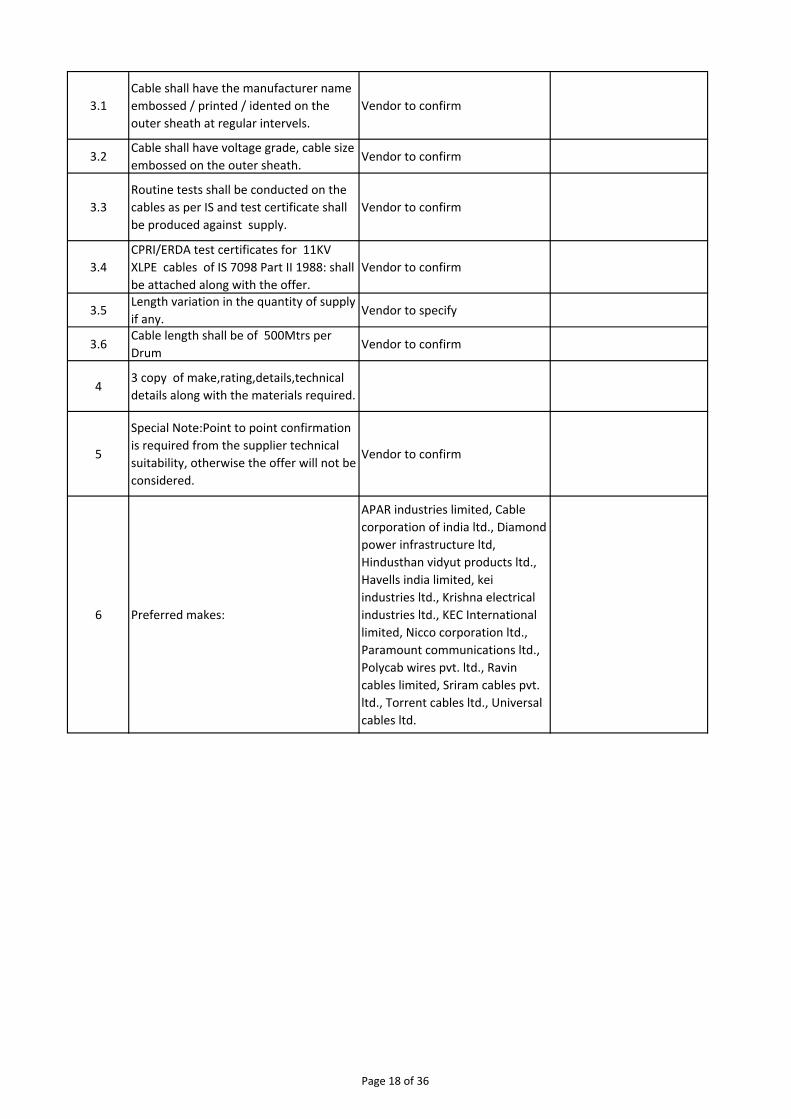
Sl. No Description/Specifications Vendor to confirm DeviationsDesign., manufacture and supply of
Medium Voltage, floor mounting, free
standing, indoor, cubicle type switchgear
panel comprising Air Circuit Breaker feeder
and conforming to the specification and
features given below.
1.0Air Circuit Breaker Make : L & T or GE or
SIEMENS or SCHNIEDER or ABB.Vendor to confirm
2.0
Incomer Breaker : 2000A, 415V, Three
Phase and neutral, draw‐out type, true, trip
free, electrically operated spring closing
type, Air Circuit Breakers having 24 V DC
shunt trip, emergency hand trip, 4No + 4NC
auxiliary contacts, ON / OFF mechanical
indication, Integral self powered current
release, current transformers of required
quantity, burden and accuracy for metering
and for protection and confirming to IEC
60947 /2 / IS 13947 ( Part 2 ).
Quantity ‐ 2 Nos.
Vendor to confirm
3.0
Outgoing Breaker : 1000A, 415V, Three
Phase and neutral, draw‐out type, true, trip
free, electrically operated spring closing
type, Air Circuit Breakers having 24V DC
shunt trip, emergency hand trip, 4No + 4NC
auxiliary contacts, ON / OFF mechanical
indication, Integral self powered current
release, current transformers of required
quantity, burden and accuracy for metering
and for Protection and confirming to IEC
60947 /2 / IS 13947 ( Part 2 ).
Quantity ‐ 16 Nos.
Vendor to confirm
3.1
Bus coupler Breaker (ACB ): 2000A, 415V,
Three Phase and neutral, draw‐out type,
true, trip free, electrically operated spring
closing type, Air Circuit Breakers having 24V
DC shunt trip, emergency hand trip, 4No +
4NC auxiliary contacts, ON / OFF
mechanical indication and confirming to
IEC 60947 /2 / IS 13947 ( Part 2 )
Quantity ‐ 1 No.
ANNEXURE‐VI
TECHNICAL SPECIFICATION FOR MV SWITCH GEAR PANEL
Page 19 of 36
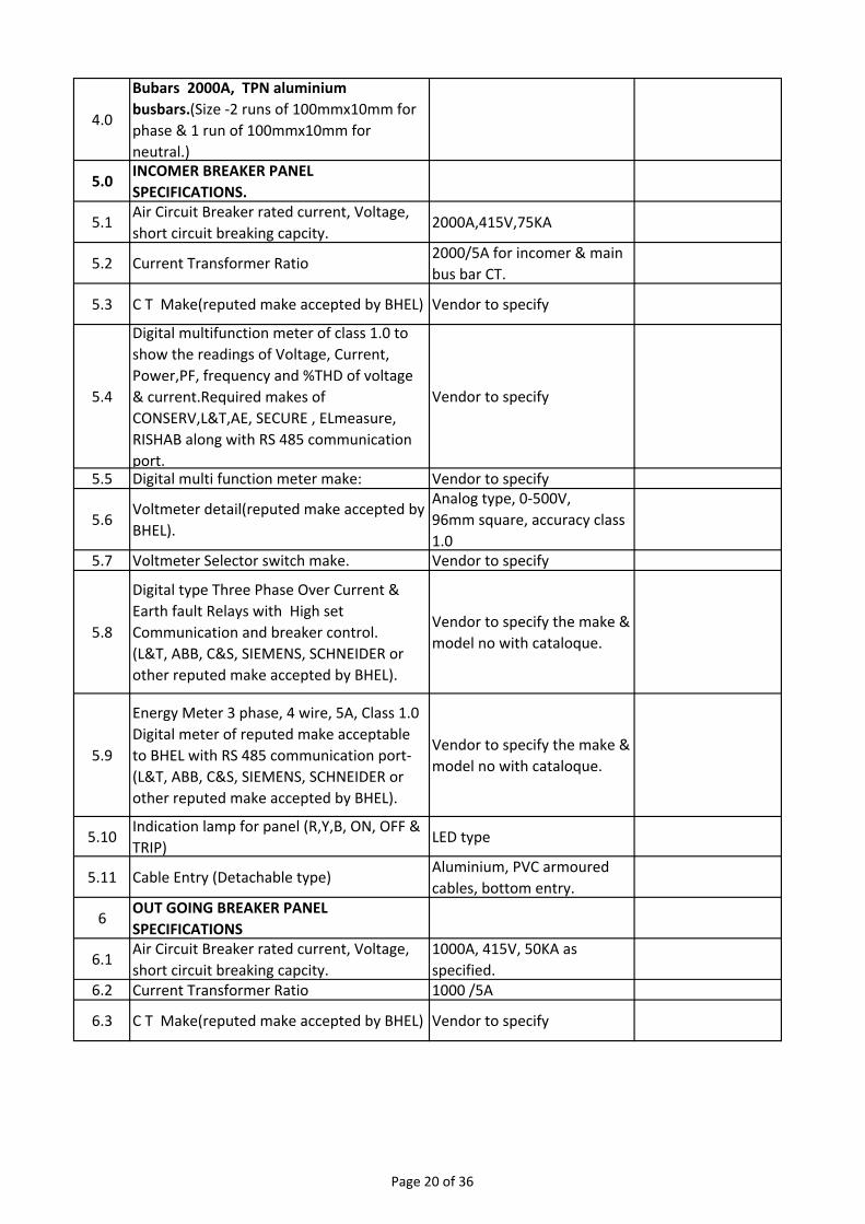
4.0
Bubars 2000A, TPN aluminium
busbars.(Size ‐2 runs of 100mmx10mm for
phase & 1 run of 100mmx10mm for
neutral.)
5.0INCOMER BREAKER PANEL
SPECIFICATIONS.
5.1Air Circuit Breaker rated current, Voltage,
short circuit breaking capcity.2000A,415V,75KA
5.2 Current Transformer Ratio2000/5A for incomer & main
bus bar CT.
5.3 C T Make(reputed make accepted by BHEL) Vendor to specify
5.4
Digital multifunction meter of class 1.0 to
show the readings of Voltage, Current,
Power,PF, frequency and %THD of voltage
& current.Required makes of
CONSERV,L&T,AE, SECURE , ELmeasure,
RISHAB along with RS 485 communication
port.
Vendor to specify
5.5 Digital multi function meter make: Vendor to specify
5.6Voltmeter detail(reputed make accepted by
BHEL).
Analog type, 0‐500V,
96mm square, accuracy class
1.05.7 Voltmeter Selector switch make. Vendor to specify
5.8
Digital type Three Phase Over Current &
Earth fault Relays with High set
Communication and breaker control.
(L&T, ABB, C&S, SIEMENS, SCHNEIDER or
other reputed make accepted by BHEL).
Vendor to specify the make &
model no with cataloque.
5.9
Energy Meter 3 phase, 4 wire, 5A, Class 1.0
Digital meter of reputed make acceptable
to BHEL with RS 485 communication port‐
(L&T, ABB, C&S, SIEMENS, SCHNEIDER or
other reputed make accepted by BHEL).
Vendor to specify the make &
model no with cataloque.
5.10Indication lamp for panel (R,Y,B, ON, OFF &
TRIP)LED type
5.11 Cable Entry (Detachable type)Aluminium, PVC armoured
cables, bottom entry.
6OUT GOING BREAKER PANEL
SPECIFICATIONS
6.1Air Circuit Breaker rated current, Voltage,
short circuit breaking capcity.
1000A, 415V, 50KA as
specified.6.2 Current Transformer Ratio 1000 /5A
6.3 C T Make(reputed make accepted by BHEL) Vendor to specify
Page 20 of 36
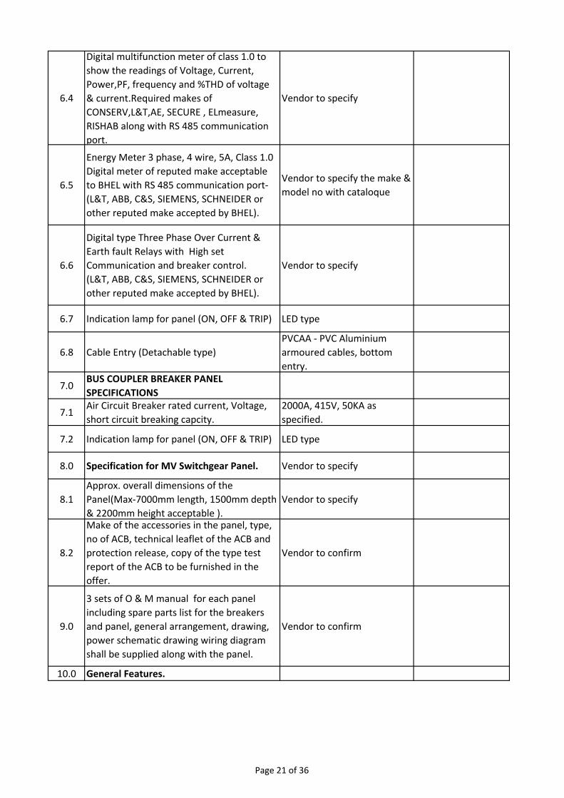
6.4
Digital multifunction meter of class 1.0 to
show the readings of Voltage, Current,
Power,PF, frequency and %THD of voltage
& current.Required makes of
CONSERV,L&T,AE, SECURE , ELmeasure,
RISHAB along with RS 485 communication
port.
Vendor to specify
6.5
Energy Meter 3 phase, 4 wire, 5A, Class 1.0
Digital meter of reputed make acceptable
to BHEL with RS 485 communication port‐
(L&T, ABB, C&S, SIEMENS, SCHNEIDER or
other reputed make accepted by BHEL).
Vendor to specify the make &
model no with cataloque
6.6
Digital type Three Phase Over Current &
Earth fault Relays with High set
Communication and breaker control.
(L&T, ABB, C&S, SIEMENS, SCHNEIDER or
other reputed make accepted by BHEL).
Vendor to specify
6.7 Indication lamp for panel (ON, OFF & TRIP) LED type
6.8 Cable Entry (Detachable type)
PVCAA ‐ PVC Aluminium
armoured cables, bottom
entry.
7.0BUS COUPLER BREAKER PANEL
SPECIFICATIONS
7.1Air Circuit Breaker rated current, Voltage,
short circuit breaking capcity.
2000A, 415V, 50KA as
specified.
7.2 Indication lamp for panel (ON, OFF & TRIP) LED type
8.0 Specification for MV Switchgear Panel. Vendor to specify
8.1
Approx. overall dimensions of the
Panel(Max‐7000mm length, 1500mm depth
& 2200mm height acceptable ).
Vendor to specify
8.2
Make of the accessories in the panel, type,
no of ACB, technical leaflet of the ACB and
protection release, copy of the type test
report of the ACB to be furnished in the
offer.
Vendor to confirm
9.0
3 sets of O & M manual for each panel
including spare parts list for the breakers
and panel, general arrangement, drawing,
power schematic drawing wiring diagram
shall be supplied along with the panel.
Vendor to confirm
10.0 General Features.
Page 21 of 36
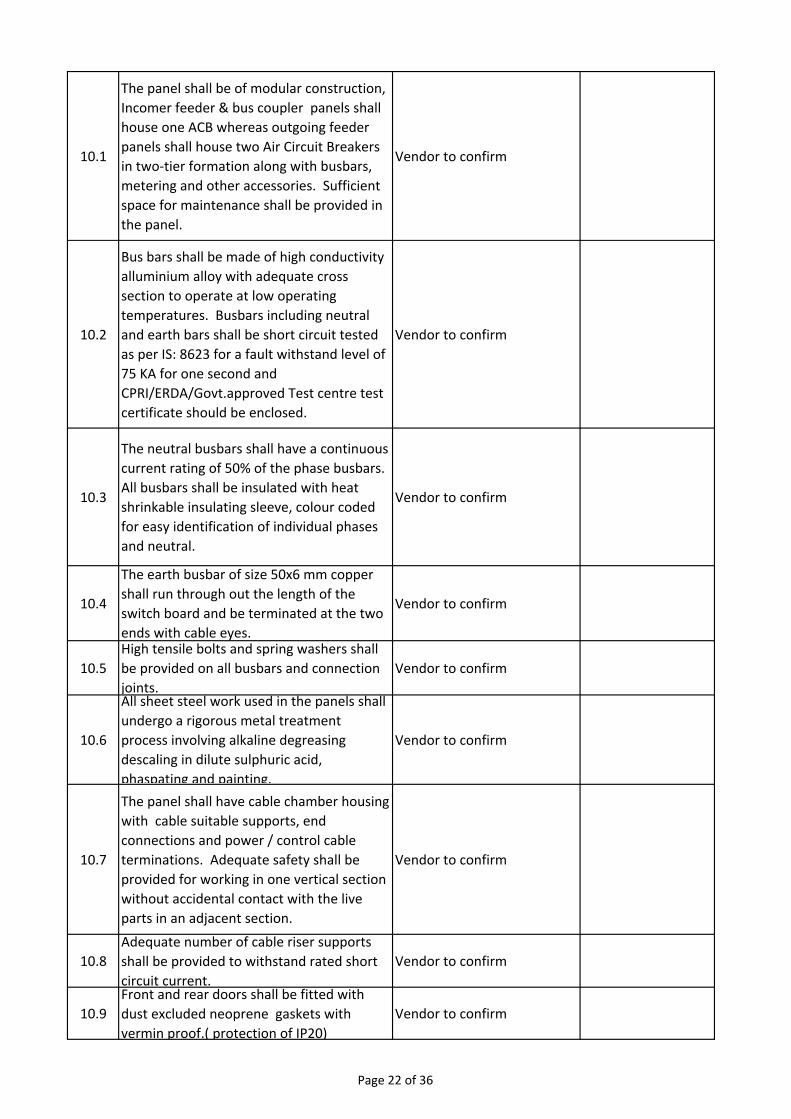
10.1
The panel shall be of modular construction,
Incomer feeder & bus coupler panels shall
house one ACB whereas outgoing feeder
panels shall house two Air Circuit Breakers
in two‐tier formation along with busbars,
metering and other accessories. Sufficient
space for maintenance shall be provided in
the panel.
Vendor to confirm
10.2
Bus bars shall be made of high conductivity
alluminium alloy with adequate cross
section to operate at low operating
temperatures. Busbars including neutral
and earth bars shall be short circuit tested
as per IS: 8623 for a fault withstand level of
75 KA for one second and
CPRI/ERDA/Govt.approved Test centre test
certificate should be enclosed.
Vendor to confirm
10.3
The neutral busbars shall have a continuous
current rating of 50% of the phase busbars.
All busbars shall be insulated with heat
shrinkable insulating sleeve, colour coded
for easy identification of individual phases
and neutral.
Vendor to confirm
10.4
The earth busbar of size 50x6 mm copper
shall run through out the length of the
switch board and be terminated at the two
ends with cable eyes.
Vendor to confirm
10.5
High tensile bolts and spring washers shall
be provided on all busbars and connection
joints.
Vendor to confirm
10.6
All sheet steel work used in the panels shall
undergo a rigorous metal treatment
process involving alkaline degreasing
descaling in dilute sulphuric acid,
phaspating and painting.
Vendor to confirm
10.7
The panel shall have cable chamber housing
with cable suitable supports, end
connections and power / control cable
terminations. Adequate safety shall be
provided for working in one vertical section
without accidental contact with the live
parts in an adjacent section.
Vendor to confirm
10.8
Adequate number of cable riser supports
shall be provided to withstand rated short
circuit current.
Vendor to confirm
10.9
Front and rear doors shall be fitted with
dust excluded neoprene gaskets with
vermin proof.( protection of IP20)
Vendor to confirm
Page 22 of 36
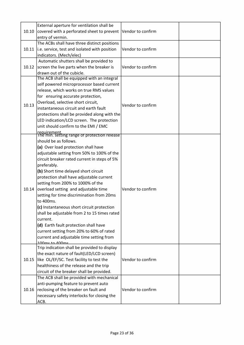
10.10
External aperture for ventilation shall be
covered with a perforated sheet to prevent
entry of vermin.
Vendor to confirm
10.11
The ACBs shall have three distinct positions
i.e. service, test and isolated with position
indicators. (Mech/elec)
Vendor to confirm
10.12
Automatic shutters shall be provided to
screen the live parts when the breaker is
drawn out of the cubicle.
Vendor to confirm
10.13
The ACB shall be equipped with an integral
self powered microprocessor based current
release, which works on true RMS values
for ensuring accurate protection,
Overload, selective short circuit,
instantaneous circuit and earth fault
protections shall be provided along with the
LED indication/LCD screen. The protection
unit should confirm to the EMI / EMC
requirement.
Vendor to confirm
10.14
The min. setting range of protection release
should be as follows.
(a) Over load protection shall have
adjustable setting from 50% to 100% of the
circuit breaker rated current in steps of 5%
preferably.
(b) Short time delayed short circuit
protection shall have adjustable current
setting from 200% to 1000% of the
overload setting and adjustable time
setting for time discrimination from 20ms
to 400ms.
(c) Instantaneous short circuit protection
shall be adjustable from 2 to 15 times rated
current.
(d) Earth fault protection shall have
current setting from 20% to 60% of rated
current and adjustable time setting from
100ms to 400ms
Vendor to confirm
10.15
Trip indication shall be provided to display
the exact nature of fault(LED/LCD screen)
like OL/EF/SC. Test facility to test the
healthiness of the release and the trip
circuit of the breaker shall be provided.
Vendor to confirm
10.16
The ACB shall be provided with mechanical
anti‐pumping feature to prevent auto
reclosing of the breaker on fault and
necessary safety interlocks for closing the
ACB.
Vendor to confirm
Page 23 of 36
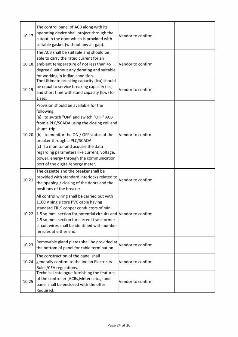
10.17
The control panel of ACB along with its
operating device shall project through the
cutout in the door which is provided with
suitable gasket (without any air gap).
Vendor to confirm
10.18
The ACB shall be suitable and should be
able to carry the rated current for an
ambient temperature of not less than 45
degree C without any derating and suitable
for working in Indian condition.
Vendor to confirm
10.19
The Ultimate breaking capacity (lcu) should
be equal to service breaking capacity (lcs)
and short time withstand capacity (lcw) for
1 sec.
Vendor to confirm
10.20
Provision should be available for the
following.
(a) to swtich "ON" and switch "OFF" ACB
from a PLC/SCADA using the closing coil and
shunt trip.
(b) to monitor the ON / OFF status of the
breaker through a PLC/SCADA
(c) to monitor and acquire the data
regarding parameters like current, voltage,
power, energy through the communication
port of the digital/energy meter.
Vendor to confirm
10.21
The cassette and the breaker shall be
provided with standard interlocks related to
the opening / closing of the doors and the
positions of the breaker.
Vendor to confirm
10.22
All control wiring shall be carried out with
1100 V single core PVC cable having
standard FRLS copper conductors of min.
1.5 sq.mm. section for potential circuits and
2.5 sq.mm. section for current transformer
circuit wires shall be identified with number
ferrules at either end.
Vendor to confirm
10.23Removable gland plates shall be provided at
the bottom of panel for cable termination.Vendor to confirm
10.24
The construction of the panel shall
generally confirm to the Indian Electricity
Rules/CEA regulations.
Vendor to confirm
10.25
Technical catalogue furnishing the features
of the controller (ACBs,Meters etc.,) and
panel shall be enclosed with the offer
Required.
Vendor to confirm
Page 24 of 36
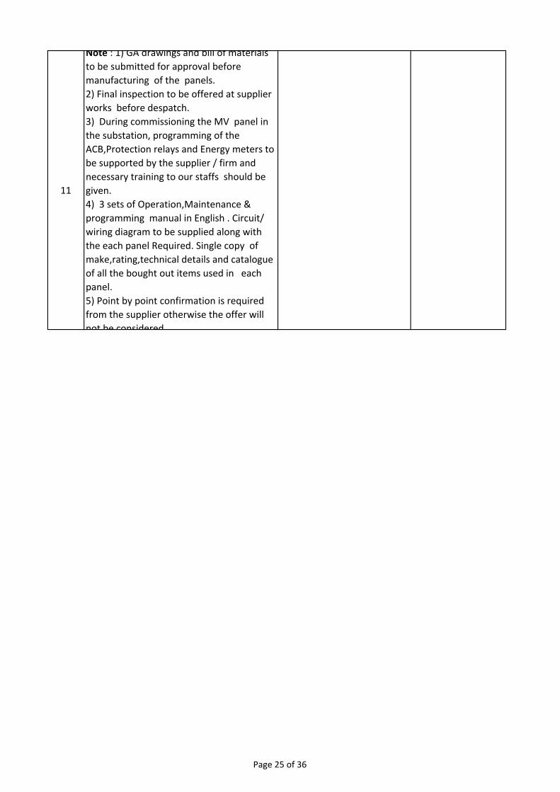
11
Note : 1) GA drawings and bill of materials
to be submitted for approval before
manufacturing of the panels.
2) Final inspection to be offered at supplier
works before despatch.
3) During commissioning the MV panel in
the substation, programming of the
ACB,Protection relays and Energy meters to
be supported by the supplier / firm and
necessary training to our staffs should be
given.
4) 3 sets of Operation,Maintenance &
programming manual in English . Circuit/
wiring diagram to be supplied along with
the each panel Required. Single copy of
make,rating,technical details and catalogue
of all the bought out items used in each
panel.
5) Point by point confirmation is required
from the supplier otherwise the offer will
not be considered
Page 25 of 36
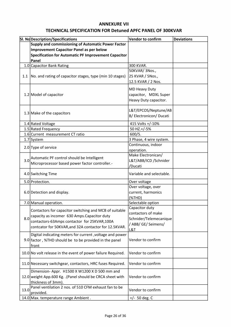
Sl. NoDescription/Specifications Vendor to confirm DeviationsSupply and commissioning of Automatic Power Factor
Improvement Capacitor Panel as per below
Specification for Automatic PF Improvement Capacitor
Panel1.0 Capacitor Bank Rating 300 KVAR.
1.1 No. and rating of capacitor stages, type (min 10 stages)
50KVAR/ 3Nos.,
25 KVAR / 5Nos.,
12.5 KVAR / 2 Nos.
1.2 Model of capacitor
MD Heavy Duty
capacitor, MDXL Super
Heavy Duty capacitor.
1.3 Make of the capacitorsL&T/EPCOS/Neptune/AB
B/ Electronicon/ Ducati
1.4 Rated Voltage 415 Volts +/‐10%1.5 Rated Frequency 50 HZ.+/‐5%1.6 Current measurement CT ratio 600/5.1.7 System 3 Phase, 4 wire system.
2.0 Type of service Continuous, indoor
operation.
3.0Automatic PF control should be Intelligent
Microprocessor based power factor controller.‐
Make Electronican/
L&T/ABB/ICD /Schnider
/Ducati
4.0 Switching Time Variable and selectable.
5.0 Protection. Over voltage
6.0 Detection and display.
Over voltage, over
current, harmonics
(%THD)7.0 Manual operation. Selectable option
8.0
Contactors for capacitor switching and MCB of suitable
capacity as incomer 630 Amps.Capacitor duty
contactors‐63Amps contactor for 25KVAR,100A
contcator for 50KVAR,and 32A contactor for 12.5KVAR.
Capacitor duty
contactors of make
Schnider/Telemecanique
/ ABB/ GE/ Seimens/
L&T
9.0Digital indicating meters for current ,voltage and power
factor , %THD should be to be provided in the panel
front
Vendor to confirm
10.0 No volt release in the event of power failure Required. Vendor to confirm
11.0 Necessary switchgear, contactors, HRC fuses Required. Vendor to confirm
12.0
Dimension‐ Appr. H1500 X W1200 X D 500 mm and
weight App.600 Kg. .(Panel should be CRCA sheet with
thickness of 3mm).
Vendor to confirm
13.0Panel ventilation 2 nos. of 510 CFM exhaust fan to be
provided.Vendor to confirm
14.0 Max. temperature range Ambient . +/‐ 50 deg. C
ANNEXURE VII
TECHNICAL SPECIFICATION FOR Detuned APFC PANEL OF 300KVAR
Page 26 of 36
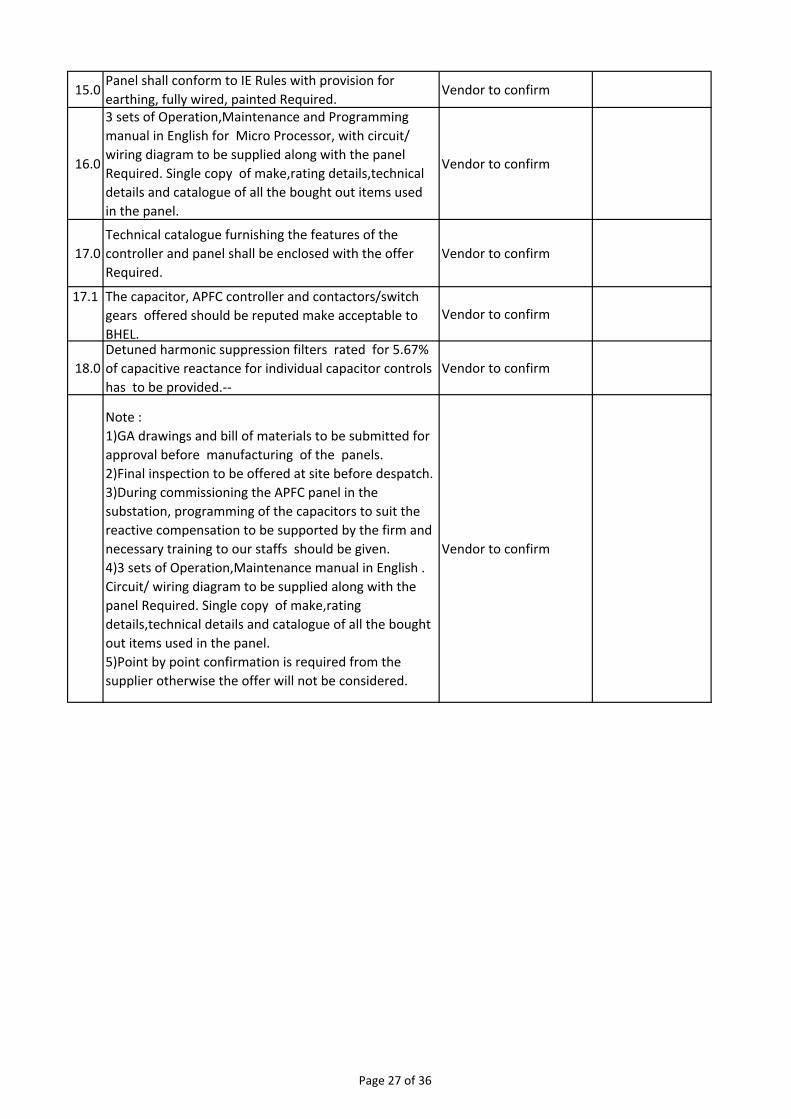
15.0Panel shall conform to IE Rules with provision for
earthing, fully wired, painted Required.Vendor to confirm
16.0
3 sets of Operation,Maintenance and Programming
manual in English for Micro Processor, with circuit/
wiring diagram to be supplied along with the panel
Required. Single copy of make,rating details,technical
details and catalogue of all the bought out items used
in the panel.
Vendor to confirm
17.0
Technical catalogue furnishing the features of the
controller and panel shall be enclosed with the offer
Required.
Vendor to confirm
17.1 The capacitor, APFC controller and contactors/switch
gears offered should be reputed make acceptable to
BHEL.
Vendor to confirm
18.0
Detuned harmonic suppression filters rated for 5.67%
of capacitive reactance for individual capacitor controls
has to be provided.‐‐
Vendor to confirm
Note :
1)GA drawings and bill of materials to be submitted for
approval before manufacturing of the panels.
2)Final inspection to be offered at site before despatch.
3)During commissioning the APFC panel in the
substation, programming of the capacitors to suit the
reactive compensation to be supported by the firm and
necessary training to our staffs should be given.
4)3 sets of Operation,Maintenance manual in English .
Circuit/ wiring diagram to be supplied along with the
panel Required. Single copy of make,rating
details,technical details and catalogue of all the bought
out items used in the panel.
5)Point by point confirmation is required from the
supplier otherwise the offer will not be considered.
Vendor to confirm
Page 27 of 36
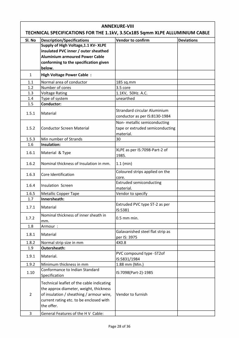
Sl. No Description/Specifications Vendor to confirm DeviationsSupply of High Voltage,1.1 KV‐ XLPE
insulated PVC inner / outer sheathed
Aluminium armoured Power Cable
conforming to the specification given
below.
1 High Voltage Power Cable :
1.1 Normal area of conductor 185 sq.mm1.2 Number of cores 3.5 core1.3 Voltage Rating 1.1KV, 50Hz. A.C.1.4 Type of system unearthed1.5 Conductor:
1.5.1 MaterialStrandard circular Aluminium
conductor as per IS:8130‐1984
1.5.2 Conductor Screen Material
Non‐ metallic semiconducting
tape or extruded semiconducting
material.1.5.3 Min number of Strands 301.6 Insulation:
1.6.1 Material & TypeXLPE as per IS:7098‐Part‐2 of
1985.
1.6.2 Nominal thickness of Insulation in mm. 1.1 (min)
1.6.3 Core IdentificationColoured strips applied on the
core.
1.6.4 Insulation ScreenExtruded semiconducting
material.1.6.5 Metallic Copper Tape Vendor to specify1.7 Innersheath:
1.7.1 MaterialExtruded PVC type ST‐2 as per
IS:5381
1.7.2 Nominal thickness of inner sheath in
mm.0.5 mm min.
1.8 Armour :
1.8.1 Material Galavanished steel flat strip as
per IS: 39751.8.2 Normal strip size in mm 4X0.81.9 Outersheath:
1.9.1 Material.PVC compound type ‐ST2of
IS:5831/19841.9.2 Minimum thickness in mm 1.88 mm (Min.)
1.10Conformance to Indian Standard
SpecificationIS:7098(Part‐2)‐1985
2
Technical leaflet of the cable indicating
the approx diameter, weight, thickness
of insulation / sheathing / armour wire,
current rating etc. to be enclosed with
the offer.
Vendor to furnish
3 General Features of the H V Cable:
ANNEXURE‐VIII
TECHNICAL SPECIFICATIONS FOR THE 1.1kV, 3.5Cx185 Sqmm XLPE ALLUMINIUM CABLE
Page 28 of 36
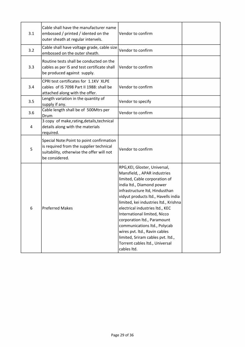
3.1
Cable shall have the manufacturer name
embossed / printed / idented on the
outer sheath at regular intervels.
Vendor to confirm
3.2Cable shall have voltage grade, cable size
embossed on the outer sheath.Vendor to confirm
3.3
Routine tests shall be conducted on the
cables as per IS and test certificate shall
be produced against supply.
Vendor to confirm
3.4
CPRI test certificates for 1.1KV XLPE
cables of IS 7098 Part II 1988: shall be
attached along with the offer.
Vendor to confirm
3.5Length variation in the quantity of
supply if any.Vendor to specify
3.6Cable length shall be of 500Mtrs per
DrumVendor to confirm
4
3 copy of make,rating,details,technical
details along with the materials
required.
5
Special Note:Point to point confirmation
is required from the supplier technical
suitability, otherwise the offer will not
be considered.
Vendor to confirm
6 Preferred Makes
RPG,KEI, Gloster, Universal,
Mansfield, , APAR industries
limited, Cable corporation of
india ltd., Diamond power
infrastructure ltd, Hindusthan
vidyut products ltd., Havells india
limited, kei industries ltd., Krishna
electrical industries ltd., KEC
International limited, Nicco
corporation ltd., Paramount
communications ltd., Polycab
wires pvt. ltd., Ravin cables
limited, Sriram cables pvt. ltd.,
Torrent cables ltd., Universal
cables ltd.
Page 29 of 36
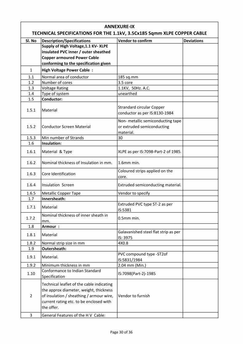
Sl. No Description/Specifications Vendor to confirm DeviationsSupply of High Voltage,1.1 KV‐ XLPE
insulated PVC inner / outer sheathed
Copper armoured Power Cable
conforming to the specification given
1 High Voltage Power Cable :
1.1 Normal area of conductor 185 sq.mm1.2 Number of cores 3.5 core1.3 Voltage Rating 1.1KV, 50Hz. A.C.1.4 Type of system unearthed1.5 Conductor:
1.5.1 MaterialStrandard circular Copper
conductor as per IS:8130‐1984
1.5.2 Conductor Screen Material
Non‐ metallic semiconducting tape
or extruded semiconducting
material.1.5.3 Min number of Strands 301.6 Insulation:
1.6.1 Material & Type XLPE as per IS:7098‐Part‐2 of 1985.
1.6.2 Nominal thickness of Insulation in mm. 1.6mm min.
1.6.3 Core IdentificationColoured strips applied on the
core.
1.6.4 Insulation Screen Extruded semiconducting material.
1.6.5 Metallic Copper Tape Vendor to specify1.7 Innersheath:
1.7.1 MaterialExtruded PVC type ST‐2 as per
IS:5381
1.7.2 Nominal thickness of inner sheath in
mm.0.5mm min.
1.8 Armour :
1.8.1 Material Galavanished steel flat strip as per
IS: 39751.8.2 Normal strip size in mm 4X0.81.9 Outersheath:
1.9.1 Material.PVC compound type ‐ST2of
IS:5831/19841.9.2 Minimum thickness in mm 2.04 mm (Min.)
1.10Conformance to Indian Standard
SpecificationIS:7098(Part‐2)‐1985
2
Technical leaflet of the cable indicating
the approx diameter, weight, thickness
of insulation / sheathing / armour wire,
current rating etc. to be enclosed with
the offer.
Vendor to furnish
3 General Features of the H V Cable:
ANNEXURE‐IX
TECHNICAL SPECIFICATIONS FOR THE 1.1kV, 3.5Cx185 Sqmm XLPE COPPER CABLE
Page 30 of 36
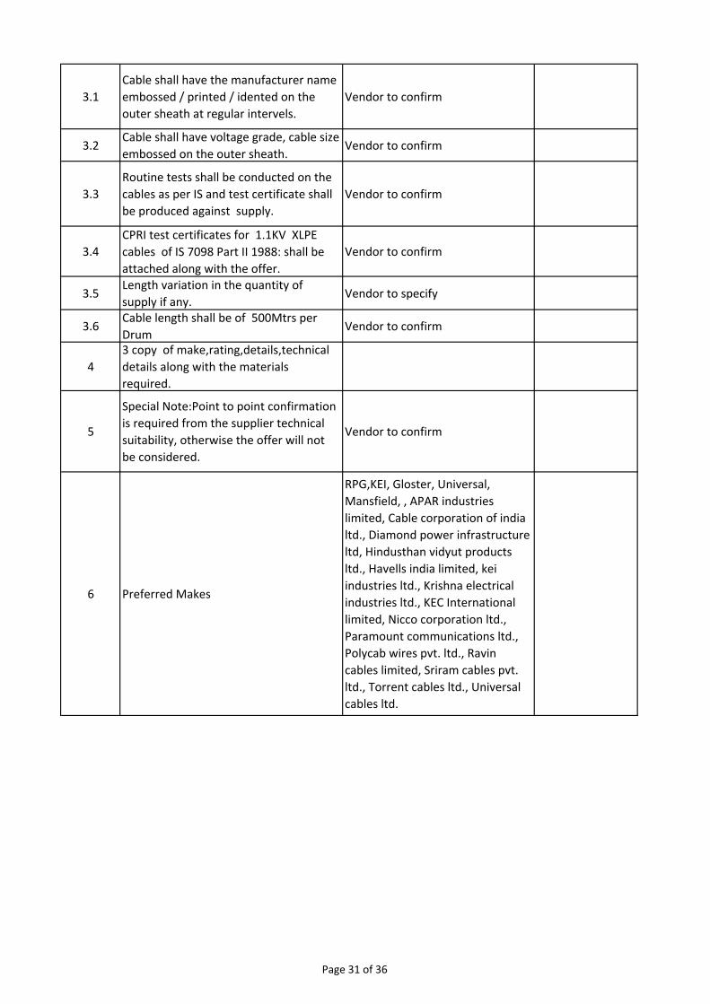
3.1
Cable shall have the manufacturer name
embossed / printed / idented on the
outer sheath at regular intervels.
Vendor to confirm
3.2Cable shall have voltage grade, cable size
embossed on the outer sheath.Vendor to confirm
3.3
Routine tests shall be conducted on the
cables as per IS and test certificate shall
be produced against supply.
Vendor to confirm
3.4
CPRI test certificates for 1.1KV XLPE
cables of IS 7098 Part II 1988: shall be
attached along with the offer.
Vendor to confirm
3.5Length variation in the quantity of
supply if any.Vendor to specify
3.6Cable length shall be of 500Mtrs per
DrumVendor to confirm
4
3 copy of make,rating,details,technical
details along with the materials
required.
5
Special Note:Point to point confirmation
is required from the supplier technical
suitability, otherwise the offer will not
be considered.
Vendor to confirm
6 Preferred Makes
RPG,KEI, Gloster, Universal,
Mansfield, , APAR industries
limited, Cable corporation of india
ltd., Diamond power infrastructure
ltd, Hindusthan vidyut products
ltd., Havells india limited, kei
industries ltd., Krishna electrical
industries ltd., KEC International
limited, Nicco corporation ltd.,
Paramount communications ltd.,
Polycab wires pvt. ltd., Ravin
cables limited, Sriram cables pvt.
ltd., Torrent cables ltd., Universal
cables ltd.
Page 31 of 36
Page 1 of 11
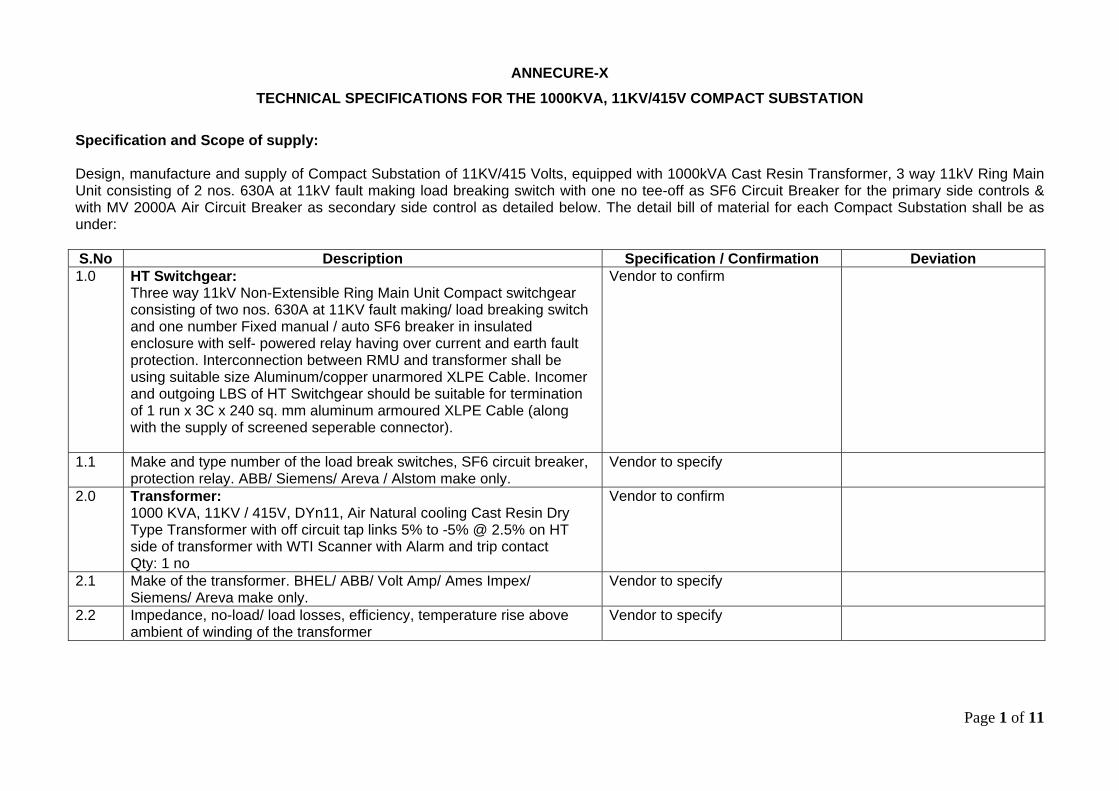
ANNECURE-X
TECHNICAL SPECIFICATIONS FOR THE 1000KVA, 11KV/415V COMPACT SUBSTATION
Specification and Scope of supply: Design, manufacture and supply of Compact Substation of 11KV/415 Volts, equipped with 1000kVA Cast Resin Transformer, 3 way 11kV Ring Main Unit consisting of 2 nos. 630A at 11kV fault making load breaking switch with one no tee-off as SF6 Circuit Breaker for the primary side controls & with MV 2000A Air Circuit Breaker as secondary side control as detailed below. The detail bill of material for each Compact Substation shall be as under: S.No Description Specification / Confirmation Deviation 1.0 HT Switchgear:
Three way 11kV Non-Extensible Ring Main Unit Compact switchgear consisting of two nos. 630A at 11KV fault making/ load breaking switch and one number Fixed manual / auto SF6 breaker in insulated enclosure with self- powered relay having over current and earth fault protection. Interconnection between RMU and transformer shall be using suitable size Aluminum/copper unarmored XLPE Cable. Incomer and outgoing LBS of HT Switchgear should be suitable for termination of 1 run x 3C x 240 sq. mm aluminum armoured XLPE Cable (along with the supply of screened seperable connector).
Vendor to confirm
1.1 Make and type number of the load break switches, SF6 circuit breaker, protection relay. ABB/ Siemens/ Areva / Alstom make only.
Vendor to specify
2.0 Transformer: 1000 KVA, 11KV / 415V, DYn11, Air Natural cooling Cast Resin Dry Type Transformer with off circuit tap links 5% to -5% @ 2.5% on HT side of transformer with WTI Scanner with Alarm and trip contact Qty: 1 no
Vendor to confirm
2.1 Make of the transformer. BHEL/ ABB/ Volt Amp/ Ames Impex/ Siemens/ Areva make only.
Vendor to specify
2.2 Impedance, no-load/ load losses, efficiency, temperature rise above ambient of winding of the transformer
Vendor to specify
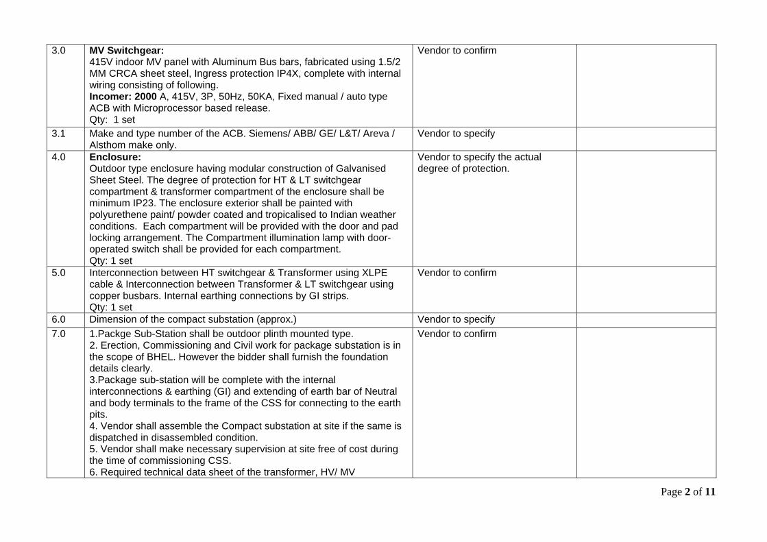
Page 2 of 11
3.0 MV Switchgear: 415V indoor MV panel with Aluminum Bus bars, fabricated using 1.5/2 MM CRCA sheet steel, Ingress protection IP4X, complete with internal wiring consisting of following. Incomer: 2000 A, 415V, 3P, 50Hz, 50KA, Fixed manual / auto type ACB with Microprocessor based release. Qty: 1 set
Vendor to confirm
3.1 Make and type number of the ACB. Siemens/ ABB/ GE/ L&T/ Areva / Alsthom make only.
Vendor to specify
4.0 Enclosure: Outdoor type enclosure having modular construction of Galvanised Sheet Steel. The degree of protection for HT & LT switchgear compartment & transformer compartment of the enclosure shall be minimum IP23. The enclosure exterior shall be painted with polyurethene paint/ powder coated and tropicalised to Indian weather conditions. Each compartment will be provided with the door and pad locking arrangement. The Compartment illumination lamp with door-operated switch shall be provided for each compartment. Qty: 1 set
Vendor to specify the actual degree of protection.
5.0 Interconnection between HT switchgear & Transformer using XLPE cable & Interconnection between Transformer & LT switchgear using copper busbars. Internal earthing connections by GI strips. Qty: 1 set
Vendor to confirm
6.0 Dimension of the compact substation (approx.) Vendor to specify 7.0 1.Packge Sub-Station shall be outdoor plinth mounted type.
2. Erection, Commissioning and Civil work for package substation is in the scope of BHEL. However the bidder shall furnish the foundation details clearly. 3.Package sub-station will be complete with the internal interconnections & earthing (GI) and extending of earth bar of Neutral and body terminals to the frame of the CSS for connecting to the earth pits. 4. Vendor shall assemble the Compact substation at site if the same is dispatched in disassembled condition. 5. Vendor shall make necessary supervision at site free of cost during the time of commissioning CSS. 6. Required technical data sheet of the transformer, HV/ MV
Vendor to confirm
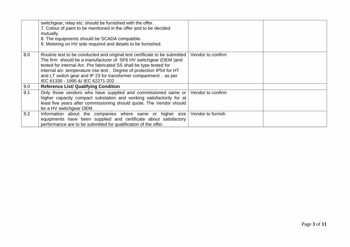
Page 3 of 11
switchgear, relay etc. should be furnished with the offer. 7. Colour of paint to be mentioned in the offer and to be decided mutually. 8. The equipments should be SCADA compatible. 9. Metering on HV side required and details to be furnished.
8.0 Routine test to be conducted and original test certificate to be submittedThe firm should be a manufacturer of SF6 HV switchgear (OEM )and tested for internal Arc .Pre fabricated SS shall be type tested for internal arc ,temperature rise test , Degree of protection IP54 for HT and LT switch gear and IP 23 for transformer compartment .. as per IEC 61330 - 1995 &/ IEC 62271-202 .
Vendor to confirm
9.0 Reference List/ Qualifying Condition 9.1 Only those vendors who have supplied and commissioned same or
higher capacity compact substation and working satisfactorily for at least five years after commissioning should quote. The Vendor should be a HV switchgear OEM.
Vendor to confirm
9.2 Information about the companies where same or higher size equipments have been supplied and certificate about satisfactory performance are to be submitted for qualification of the offer.
Vendor to furnish
Page 4 of 11
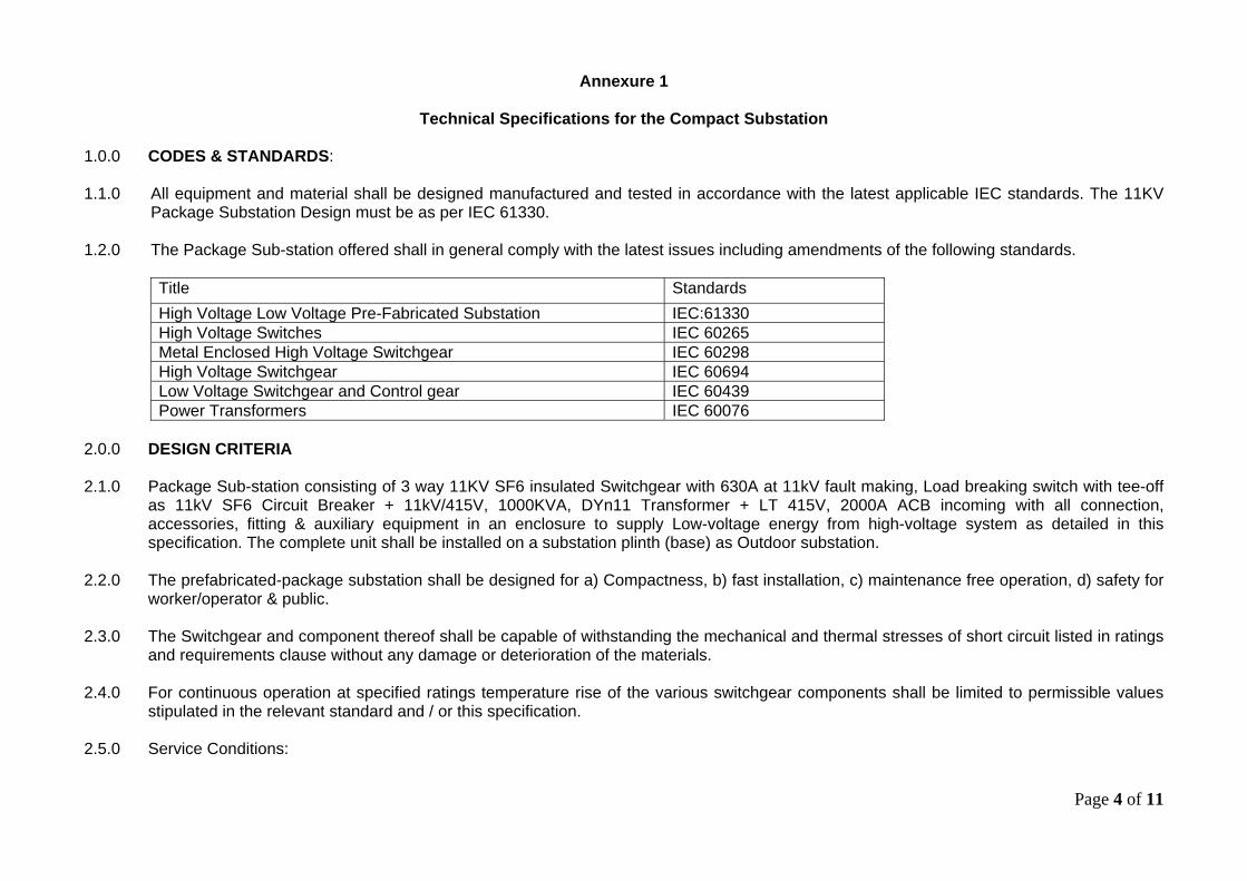
Annexure 1
Technical Specifications for the Compact Substation
1.0.0 CODES & STANDARDS: 1.1.0 All equipment and material shall be designed manufactured and tested in accordance with the latest applicable IEC standards. The 11KV
Package Substation Design must be as per IEC 61330. 1.2.0 The Package Sub-station offered shall in general comply with the latest issues including amendments of the following standards.
Title Standards High Voltage Low Voltage Pre-Fabricated Substation IEC:61330 High Voltage Switches IEC 60265 Metal Enclosed High Voltage Switchgear IEC 60298 High Voltage Switchgear IEC 60694 Low Voltage Switchgear and Control gear IEC 60439 Power Transformers IEC 60076
2.0.0 DESIGN CRITERIA 2.1.0 Package Sub-station consisting of 3 way 11KV SF6 insulated Switchgear with 630A at 11kV fault making, Load breaking switch with tee-off
as 11kV SF6 Circuit Breaker + 11kV/415V, 1000KVA, DYn11 Transformer + LT 415V, 2000A ACB incoming with all connection, accessories, fitting & auxiliary equipment in an enclosure to supply Low-voltage energy from high-voltage system as detailed in this specification. The complete unit shall be installed on a substation plinth (base) as Outdoor substation.
2.2.0 The prefabricated-package substation shall be designed for a) Compactness, b) fast installation, c) maintenance free operation, d) safety for
worker/operator & public. 2.3.0 The Switchgear and component thereof shall be capable of withstanding the mechanical and thermal stresses of short circuit listed in ratings
and requirements clause without any damage or deterioration of the materials. 2.4.0 For continuous operation at specified ratings temperature rise of the various switchgear components shall be limited to permissible values
stipulated in the relevant standard and / or this specification. 2.5.0 Service Conditions:
Page 5 of 11
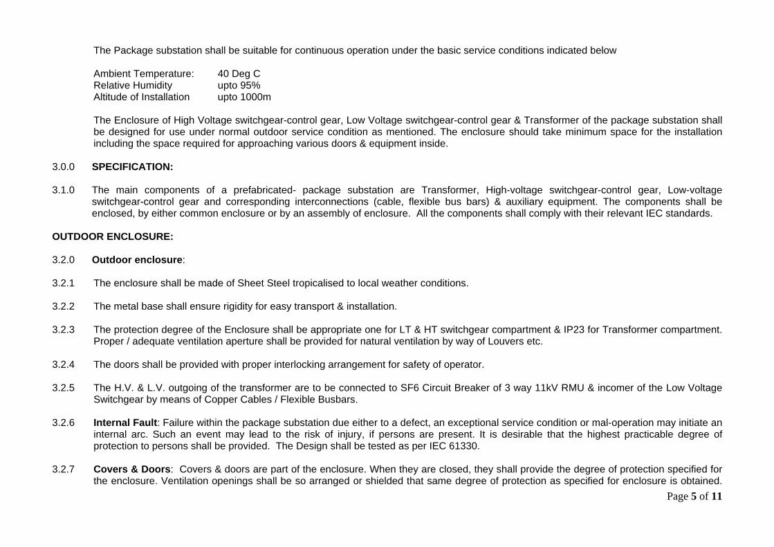
The Package substation shall be suitable for continuous operation under the basic service conditions indicated below Ambient Temperature: 40 Deg C Relative Humidity upto 95% Altitude of Installation upto 1000m The Enclosure of High Voltage switchgear-control gear, Low Voltage switchgear-control gear & Transformer of the package substation shall be designed for use under normal outdoor service condition as mentioned. The enclosure should take minimum space for the installation including the space required for approaching various doors & equipment inside.
3.0.0 SPECIFICATION: 3.1.0 The main components of a prefabricated- package substation are Transformer, High-voltage switchgear-control gear, Low-voltage
switchgear-control gear and corresponding interconnections (cable, flexible bus bars) & auxiliary equipment. The components shall be enclosed, by either common enclosure or by an assembly of enclosure. All the components shall comply with their relevant IEC standards.
OUTDOOR ENCLOSURE:
3.2.0 Outdoor enclosure: 3.2.1 The enclosure shall be made of Sheet Steel tropicalised to local weather conditions. 3.2.2 The metal base shall ensure rigidity for easy transport & installation. 3.2.3 The protection degree of the Enclosure shall be appropriate one for LT & HT switchgear compartment & IP23 for Transformer compartment.
Proper / adequate ventilation aperture shall be provided for natural ventilation by way of Louvers etc. 3.2.4 The doors shall be provided with proper interlocking arrangement for safety of operator. 3.2.5 The H.V. & L.V. outgoing of the transformer are to be connected to SF6 Circuit Breaker of 3 way 11kV RMU & incomer of the Low Voltage
Switchgear by means of Copper Cables / Flexible Busbars. 3.2.6 Internal Fault: Failure within the package substation due either to a defect, an exceptional service condition or mal-operation may initiate an
internal arc. Such an event may lead to the risk of injury, if persons are present. It is desirable that the highest practicable degree of protection to persons shall be provided. The Design shall be tested as per IEC 61330.
3.2.7 Covers & Doors: Covers & doors are part of the enclosure. When they are closed, they shall provide the degree of protection specified for
the enclosure. Ventilation openings shall be so arranged or shielded that same degree of protection as specified for enclosure is obtained.
Page 6 of 11
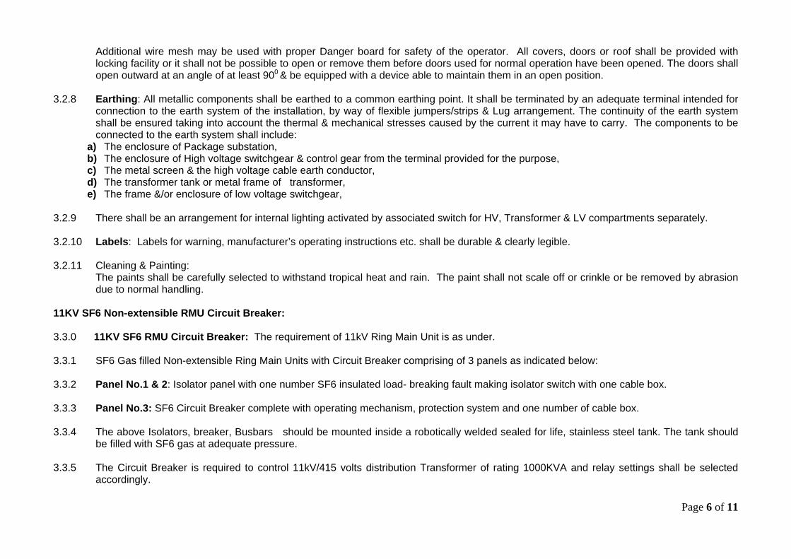
Additional wire mesh may be used with proper Danger board for safety of the operator. All covers, doors or roof shall be provided with locking facility or it shall not be possible to open or remove them before doors used for normal operation have been opened. The doors shall open outward at an angle of at least 900 & be equipped with a device able to maintain them in an open position.
3.2.8 Earthing: All metallic components shall be earthed to a common earthing point. It shall be terminated by an adequate terminal intended for
connection to the earth system of the installation, by way of flexible jumpers/strips & Lug arrangement. The continuity of the earth system shall be ensured taking into account the thermal & mechanical stresses caused by the current it may have to carry. The components to be connected to the earth system shall include:
a) The enclosure of Package substation, b) The enclosure of High voltage switchgear & control gear from the terminal provided for the purpose, c) The metal screen & the high voltage cable earth conductor, d) The transformer tank or metal frame of transformer, e) The frame &/or enclosure of low voltage switchgear,
3.2.9 There shall be an arrangement for internal lighting activated by associated switch for HV, Transformer & LV compartments separately. 3.2.10 Labels: Labels for warning, manufacturer’s operating instructions etc. shall be durable & clearly legible. 3.2.11 Cleaning & Painting:
The paints shall be carefully selected to withstand tropical heat and rain. The paint shall not scale off or crinkle or be removed by abrasion due to normal handling.
11KV SF6 Non-extensible RMU Circuit Breaker: 3.3.0 11KV SF6 RMU Circuit Breaker: The requirement of 11kV Ring Main Unit is as under. 3.3.1 SF6 Gas filled Non-extensible Ring Main Units with Circuit Breaker comprising of 3 panels as indicated below: 3.3.2 Panel No.1 & 2: Isolator panel with one number SF6 insulated load- breaking fault making isolator switch with one cable box. 3.3.3 Panel No.3: SF6 Circuit Breaker complete with operating mechanism, protection system and one number of cable box. 3.3.4 The above Isolators, breaker, Busbars should be mounted inside a robotically welded sealed for life, stainless steel tank. The tank should
be filled with SF6 gas at adequate pressure. 3.3.5 The Circuit Breaker is required to control 11kV/415 volts distribution Transformer of rating 1000KVA and relay settings shall be selected
accordingly.
Page 7 of 11
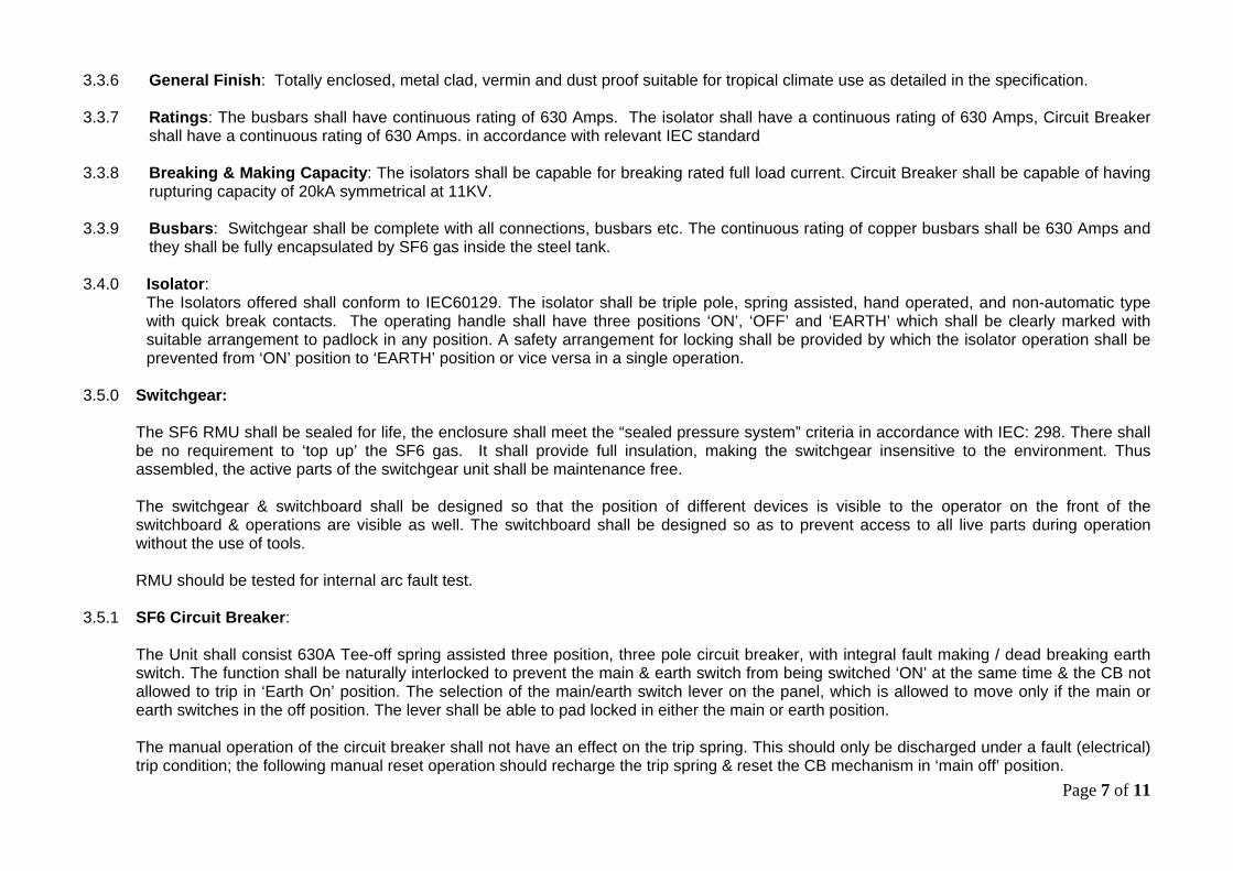
3.3.6 General Finish: Totally enclosed, metal clad, vermin and dust proof suitable for tropical climate use as detailed in the specification. 3.3.7 Ratings: The busbars shall have continuous rating of 630 Amps. The isolator shall have a continuous rating of 630 Amps, Circuit Breaker
shall have a continuous rating of 630 Amps. in accordance with relevant IEC standard 3.3.8 Breaking & Making Capacity: The isolators shall be capable for breaking rated full load current. Circuit Breaker shall be capable of having
rupturing capacity of 20kA symmetrical at 11KV. 3.3.9 Busbars: Switchgear shall be complete with all connections, busbars etc. The continuous rating of copper busbars shall be 630 Amps and
they shall be fully encapsulated by SF6 gas inside the steel tank. 3.4.0 Isolator:
The Isolators offered shall conform to IEC60129. The isolator shall be triple pole, spring assisted, hand operated, and non-automatic type with quick break contacts. The operating handle shall have three positions ‘ON’, ‘OFF’ and ‘EARTH’ which shall be clearly marked with suitable arrangement to padlock in any position. A safety arrangement for locking shall be provided by which the isolator operation shall be prevented from ‘ON’ position to ‘EARTH’ position or vice versa in a single operation.
3.5.0 Switchgear:
The SF6 RMU shall be sealed for life, the enclosure shall meet the “sealed pressure system” criteria in accordance with IEC: 298. There shall be no requirement to ‘top up’ the SF6 gas. It shall provide full insulation, making the switchgear insensitive to the environment. Thus assembled, the active parts of the switchgear unit shall be maintenance free.
The switchgear & switchboard shall be designed so that the position of different devices is visible to the operator on the front of the switchboard & operations are visible as well. The switchboard shall be designed so as to prevent access to all live parts during operation without the use of tools.
RMU should be tested for internal arc fault test.
3.5.1 SF6 Circuit Breaker:
The Unit shall consist 630A Tee-off spring assisted three position, three pole circuit breaker, with integral fault making / dead breaking earth switch. The function shall be naturally interlocked to prevent the main & earth switch from being switched ‘ON’ at the same time & the CB not allowed to trip in ‘Earth On’ position. The selection of the main/earth switch lever on the panel, which is allowed to move only if the main or earth switches in the off position. The lever shall be able to pad locked in either the main or earth position.
The manual operation of the circuit breaker shall not have an effect on the trip spring. This should only be discharged under a fault (electrical) trip condition; the following manual reset operation should recharge the trip spring & reset the CB mechanism in ‘main off’ position.
Page 8 of 11
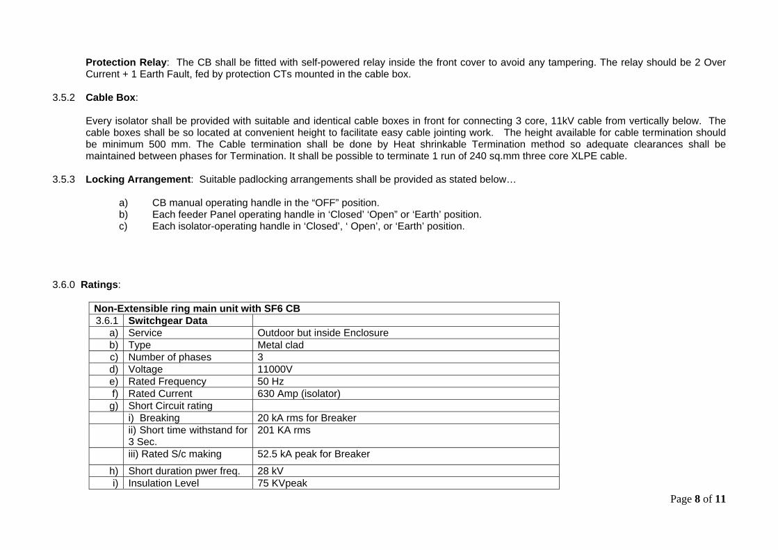
Protection Relay: The CB shall be fitted with self-powered relay inside the front cover to avoid any tampering. The relay should be 2 Over Current + 1 Earth Fault, fed by protection CTs mounted in the cable box.
3.5.2 Cable Box:
Every isolator shall be provided with suitable and identical cable boxes in front for connecting 3 core, 11kV cable from vertically below. The cable boxes shall be so located at convenient height to facilitate easy cable jointing work. The height available for cable termination should be minimum 500 mm. The Cable termination shall be done by Heat shrinkable Termination method so adequate clearances shall be maintained between phases for Termination. It shall be possible to terminate 1 run of 240 sq.mm three core XLPE cable.
3.5.3 Locking Arrangement: Suitable padlocking arrangements shall be provided as stated below…
a) CB manual operating handle in the “OFF” position. b) Each feeder Panel operating handle in ‘Closed’ ‘Open” or ‘Earth’ position. c) Each isolator-operating handle in ‘Closed’, ‘ Open’, or ‘Earth’ position.
3.6.0 Ratings:
Non-Extensible ring main unit with SF6 CB 3.6.1 Switchgear Data
a) Service Outdoor but inside Enclosure b) Type Metal clad c) Number of phases 3 d) Voltage 11000V e) Rated Frequency 50 Hz f) Rated Current 630 Amp (isolator)
g) Short Circuit rating i) Breaking 20 kA rms for Breaker ii) Short time withstand for 3 Sec.
201 KA rms
iii) Rated S/c making 52.5 kA peak for Breaker
h) Short duration pwer freq. 28 kV i) Insulation Level 75 KVpeak
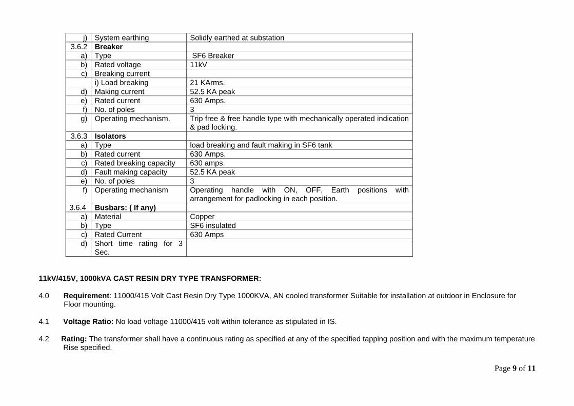
Page 9 of 11
j) System earthing Solidly earthed at substation 3.6.2 Breaker
a) Type SF6 Breaker b) Rated voltage 11kV c) Breaking current
i) Load breaking 21 KArms. d) Making current 52.5 KA peak e) Rated current 630 Amps. f) No. of poles 3
g) Operating mechanism. Trip free & free handle type with mechanically operated indication & pad locking.
3.6.3 Isolators a) Type load breaking and fault making in SF6 tank b) Rated current 630 Amps. c) Rated breaking capacity 630 amps. d) Fault making capacity 52.5 KA peak e) No. of poles 3 f) Operating mechanism Operating handle with ON, OFF, Earth positions with
arrangement for padlocking in each position. 3.6.4 Busbars: ( If any)
a) Material Copper b) Type SF6 insulated c) Rated Current 630 Amps d) Short time rating for 3
Sec.
11kV/415V, 1000kVA CAST RESIN DRY TYPE TRANSFORMER: 4.0 Requirement: 11000/415 Volt Cast Resin Dry Type 1000KVA, AN cooled transformer Suitable for installation at outdoor in Enclosure for Floor mounting. 4.1 Voltage Ratio: No load voltage 11000/415 volt within tolerance as stipulated in IS. 4.2 Rating: The transformer shall have a continuous rating as specified at any of the specified tapping position and with the maximum temperature
Rise specified.
Page 10 of 11
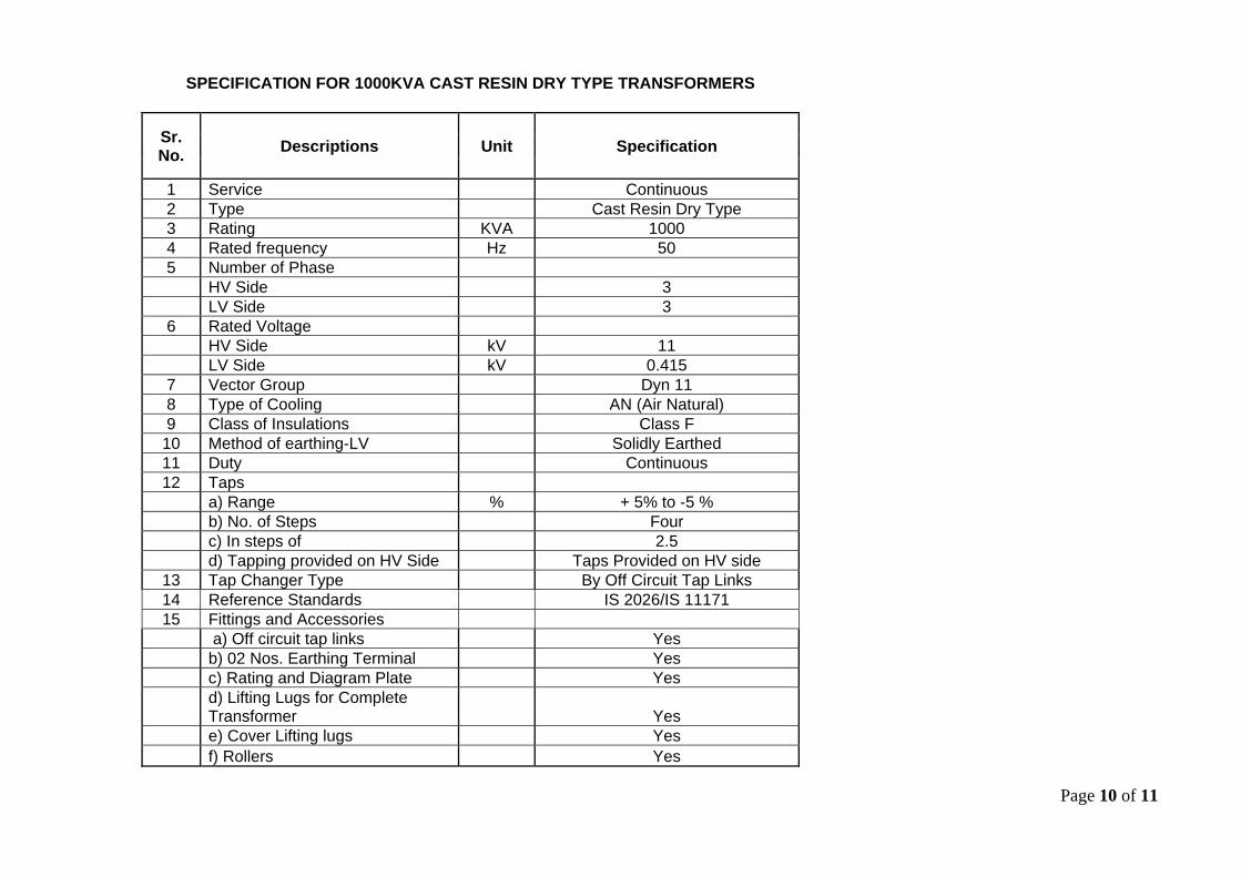
SPECIFICATION FOR 1000KVA CAST RESIN DRY TYPE TRANSFORMERS
Sr. No.
Descriptions Unit Specification
1 Service Continuous 2 Type Cast Resin Dry Type 3 Rating KVA 1000 4 Rated frequency Hz 50 5 Number of Phase HV Side 3 LV Side 3 6 Rated Voltage HV Side kV 11 LV Side kV 0.415 7 Vector Group Dyn 11 8 Type of Cooling AN (Air Natural) 9 Class of Insulations Class F
10 Method of earthing-LV Solidly Earthed 11 Duty Continuous 12 Taps a) Range % + 5% to -5 % b) No. of Steps Four c) In steps of 2.5 d) Tapping provided on HV Side Taps Provided on HV side
13 Tap Changer Type By Off Circuit Tap Links 14 Reference Standards IS 2026/IS 11171 15 Fittings and Accessories a) Off circuit tap links Yes b) 02 Nos. Earthing Terminal Yes c) Rating and Diagram Plate Yes
d) Lifting Lugs for Complete Transformer Yes
e) Cover Lifting lugs Yes f) Rollers Yes
Page 11 of 11
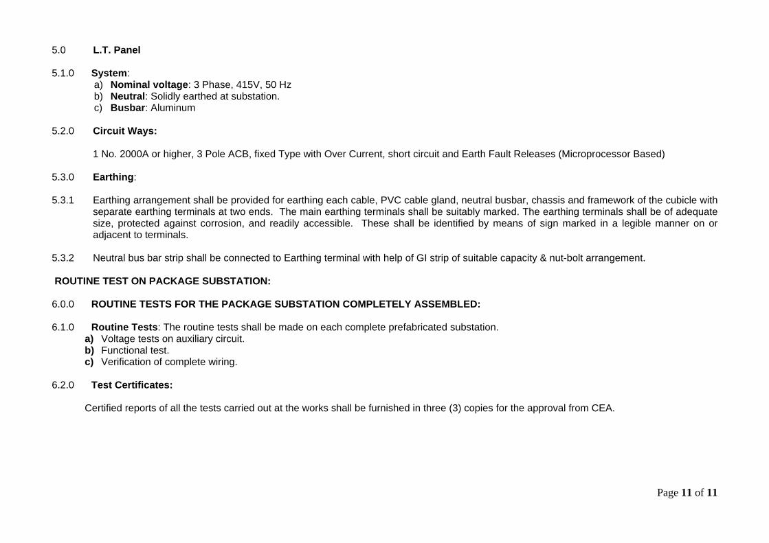
5.0 L.T. Panel 5.1.0 System:
a) Nominal voltage: 3 Phase, 415V, 50 Hz b) Neutral: Solidly earthed at substation. c) Busbar: Aluminum
5.2.0 Circuit Ways:
1 No. 2000A or higher, 3 Pole ACB, fixed Type with Over Current, short circuit and Earth Fault Releases (Microprocessor Based)
5.3.0 Earthing: 5.3.1 Earthing arrangement shall be provided for earthing each cable, PVC cable gland, neutral busbar, chassis and framework of the cubicle with
separate earthing terminals at two ends. The main earthing terminals shall be suitably marked. The earthing terminals shall be of adequate size, protected against corrosion, and readily accessible. These shall be identified by means of sign marked in a legible manner on or adjacent to terminals.
5.3.2 Neutral bus bar strip shall be connected to Earthing terminal with help of GI strip of suitable capacity & nut-bolt arrangement.
ROUTINE TEST ON PACKAGE SUBSTATION:
6.0.0 ROUTINE TESTS FOR THE PACKAGE SUBSTATION COMPLETELY ASSEMBLED: 6.1.0 Routine Tests: The routine tests shall be made on each complete prefabricated substation.
a) Voltage tests on auxiliary circuit. b) Functional test. c) Verification of complete wiring.
6.2.0 Test Certificates:
Certified reports of all the tests carried out at the works shall be furnished in three (3) copies for the approval from CEA.
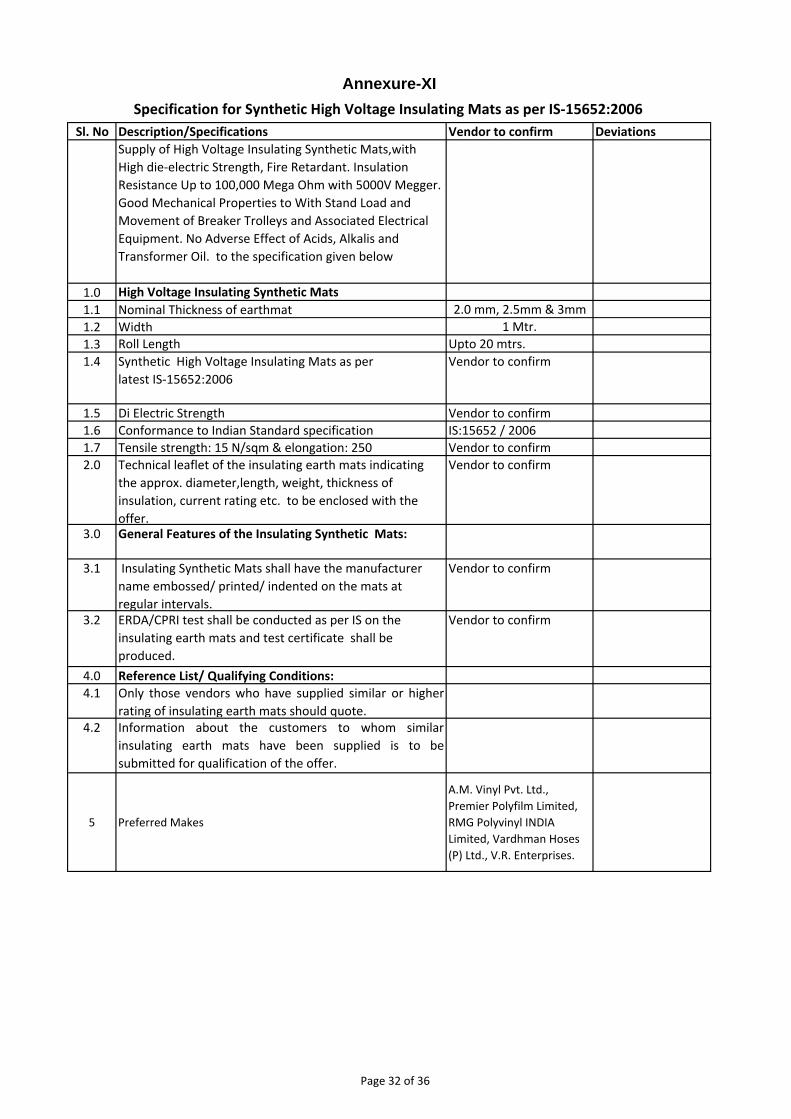
Sl. No Description/Specifications Vendor to confirm Deviations
Supply of High Voltage Insulating Synthetic Mats,with
High die‐electric Strength, Fire Retardant. Insulation
Resistance Up to 100,000 Mega Ohm with 5000V Megger.
Good Mechanical Properties to With Stand Load and
Movement of Breaker Trolleys and Associated Electrical
Equipment. No Adverse Effect of Acids, Alkalis and
Transformer Oil. to the specification given below
1.0 High Voltage Insulating Synthetic Mats
1.1 Nominal Thickness of earthmat 2.0 mm, 2.5mm & 3mm
1.2 Width 1 Mtr.
1.3 Roll Length Upto 20 mtrs.
1.4 Synthetic High Voltage Insulating Mats as per
latest IS‐15652:2006
Vendor to confirm
1.5 Di Electric Strength Vendor to confirm
1.6 Conformance to Indian Standard specification IS:15652 / 2006
1.7 Tensile strength: 15 N/sqm & elongation: 250 Vendor to confirm
2.0 Technical leaflet of the insulating earth mats indicating
the approx. diameter,length, weight, thickness of
insulation, current rating etc. to be enclosed with the
offer.
Vendor to confirm
3.0 General Features of the Insulating Synthetic Mats:
3.1 Insulating Synthetic Mats shall have the manufacturer
name embossed/ printed/ indented on the mats at
regular intervals.
Vendor to confirm
3.2 ERDA/CPRI test shall be conducted as per IS on the
insulating earth mats and test certificate shall be
produced.
Vendor to confirm
4.0 Reference List/ Qualifying Conditions:
4.1 Only those vendors who have supplied similar or higher
rating of insulating earth mats should quote.4.2 Information about the customers to whom similar
insulating earth mats have been supplied is to be
submitted for qualification of the offer.
5 Preferred Makes
A.M. Vinyl Pvt. Ltd.,
Premier Polyfilm Limited,
RMG Polyvinyl INDIA
Limited, Vardhman Hoses
(P) Ltd., V.R. Enterprises.
Specification for Synthetic High Voltage Insulating Mats as per IS‐15652:2006
Annexure-XI
Page 32 of 36
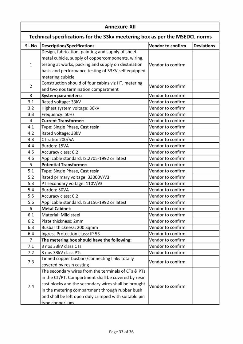
Sl. No Description/Specifications Vendor to confirm Deviations
1
Design, fabrication, painting and supply of sheet
metal cubicle, supply of coppercomponents, wiring,
testing at works, packing and supply on destination
basis and performance testing of 33KV self equipped
metering cubicle
Vendor to confirm
2Construction should of four cabins viz HT, metering
and two nos termination compartmentVendor to confirm
3 System parameters: Vendor to confirm
3.1 Rated voltage: 33kV Vendor to confirm
3.2 Highest system voltage: 36kV Vendor to confirm
3.3 Frequency: 50Hz Vendor to confirm
4 Current Transformer: Vendor to confirm
4.1 Type: Single Phase, Cast resin Vendor to confirm
4.2 Rated voltage: 33kV Vendor to confirm
4.3 CT ratio: 200/5A Vendor to confirm
4.4 Burden: 15VA Vendor to confirm
4.5 Accuracy class: 0.2 Vendor to confirm
4.6 Applicable standard: IS:2705‐1992 or latest Vendor to confirm
5 Potential Transformer: Vendor to confirm
5.1 Type: Single Phase, Cast resin Vendor to confirm
5.2 Rated primary voltage: 33000V/√3 Vendor to confirm
5.3 PT secondary voltage: 110V/√3 Vendor to confirm
5.4 Burden: 50VA Vendor to confirm
5.5 Accuracy class: 0.2 Vendor to confirm
5.6 Applicable standard: IS:3156‐1992 or latest Vendor to confirm
6 Metal Cabinet: Vendor to confirm
6.1 Material: Mild steel Vendor to confirm
6.2 Plate thickness: 2mm Vendor to confirm
6.3 Busbar thickness: 200 Sqmm Vendor to confirm
6.4 Ingress Protection class: IP 53 Vendor to confirm
7 The metering box should have the following: Vendor to confirm
7.1 3 nos 33kV class CTs Vendor to confirm
7.2 3 nos 33kV class PTs Vendor to confirm
7.3Tinned copper busbars/connecting links totally
covered by resin castingVendor to confirm
7.4
The secondary wires from the terminals of CTs & PTs
in the CT/PT. Compartment shall be covered by resin
cast blocks and the secondary wires shall be brought
in the metering compartment through rubber bush
and shall be left open duly crimped with suitable pin
type copper lugs
Vendor to confirm
Technical specifications for the 33kv meetering box as per the MSEDCL norms
Annexure‐XII
Page 33 of 36
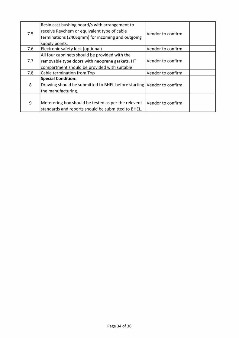
7.5
Resin cast bushing board/s with arrangement to
receive Reychem or equivalent type of cable
terminations (240Sqmm) for incoming and outgoing
supply points.
Vendor to confirm
7.6 Electronic safety lock (optional) Vendor to confirm
7.7All four cabninets should be provided with the
removable type doors with neoprene gaskets. HT
compartment should be provided with suitable
Vendor to confirm
7.8 Cable termination from Top Vendor to confirm
8
Special Condition:
Drawing should be submitted to BHEL before starting
the manufacturing.
Vendor to confirm
9 Metetering box should be tested as per the relevent
standards and reports should be submitted to BHEL.
Vendor to confirm
Page 34 of 36
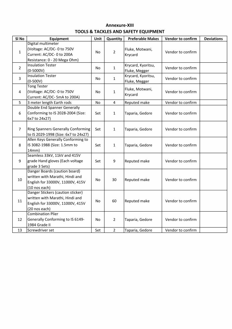
Sl No Equipment Unit Quantity Preferable Makes Vendor to confirm Deviations
1
Digital multimeter
(Voltage: AC/DC‐ 0 to 750V
Current: AC/DC‐ 0 to 200A
Resistance: 0 ‐ 20 Mega Ohm)
No 2Fluke, Motwani,
KrycardVendor to confirm
2Insulation Tester
(0‐5000V)No 1
Krycard, Kyoritsu,
Fluke, MeggerVendor to confirm
3Insulation Tester
(0‐500V)No 1
Krycard, Kyoritsu,
Fluke, MeggerVendor to confirm
4
Tong Tester
(Voltage: AC/DC‐ 0 to 750V
Current: AC/DC‐ 5mA to 200A)
No 1Fluke, Motwani,
KrycardVendor to confirm
5 3 meter length Earth rods No 4 Reputed make Vendor to confirm
6
Double End Spanner Generally
Conforming to IS 2028‐2004 (Size:
6x7 to 24x27)
Set 1 Taparia, Gedore Vendor to confirm
7 Ring Spanners Generally Conforming
to IS 2029‐1998 (Size: 6x7 to 24x27)
Set 1 Taparia, Gedore Vendor to confirm
8
Allen Keys Generally Conforming to
IS 3082‐1988 (Size: 1.5mm to
14mm)
Set 1 Taparia, Gedore Vendor to confirm
9
Seamless 33kV, 11kV and 415V
grade Hand gloves (Each voltage
grade 3 Sets)
Set 9 Reputed make Vendor to confirm
10
Danger Boards (caution board)
written with Marathi, Hindi and
English for 33000V, 11000V, 415V
(10 nos each)
No 30 Reputed make Vendor to confirm
11
Danger Stickers (caution sticker)
written with Marathi, Hindi and
English for 33000V, 11000V, 415V
(20 nos each)
No 60 Reputed make Vendor to confirm
12
Combination Plier
Generally Conforming to IS 6149‐
1984 Grade II
No 2 Taparia, Gedore Vendor to confirm
13 Screwdriver set Set 2 Taparia, Gedore Vendor to confirm
Annexure‐XIII
TOOLS & TACKLES AND SAFETY EQUIPMENT
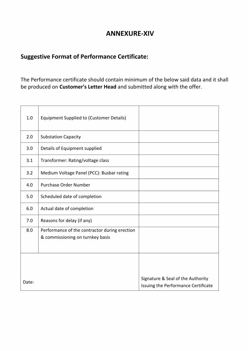
ANNEXURE‐XIV
Suggestive Format of Performance Certificate:
The Performance certificate should contain minimum of the below said data and it shall be produced on Customer's Letter Head and submitted along with the offer.
1.0 Equipment Supplied to (Customer Details)
2.0 Substation Capacity
3.0 Details of Equipment supplied
3.1 Transformer: Rating/voltage class
3.2 Medium Voltage Panel (PCC): Busbar rating
4.0 Purchase Order Number
5.0 Scheduled date of completion
6.0 Actual date of completion
7.0 Reasons for delay (if any)
8.0 Performance of the contractor during erection
& commissioning on turnkey basis
Date:
Signature & Seal of the Authority
Issuing the Performance Certificate
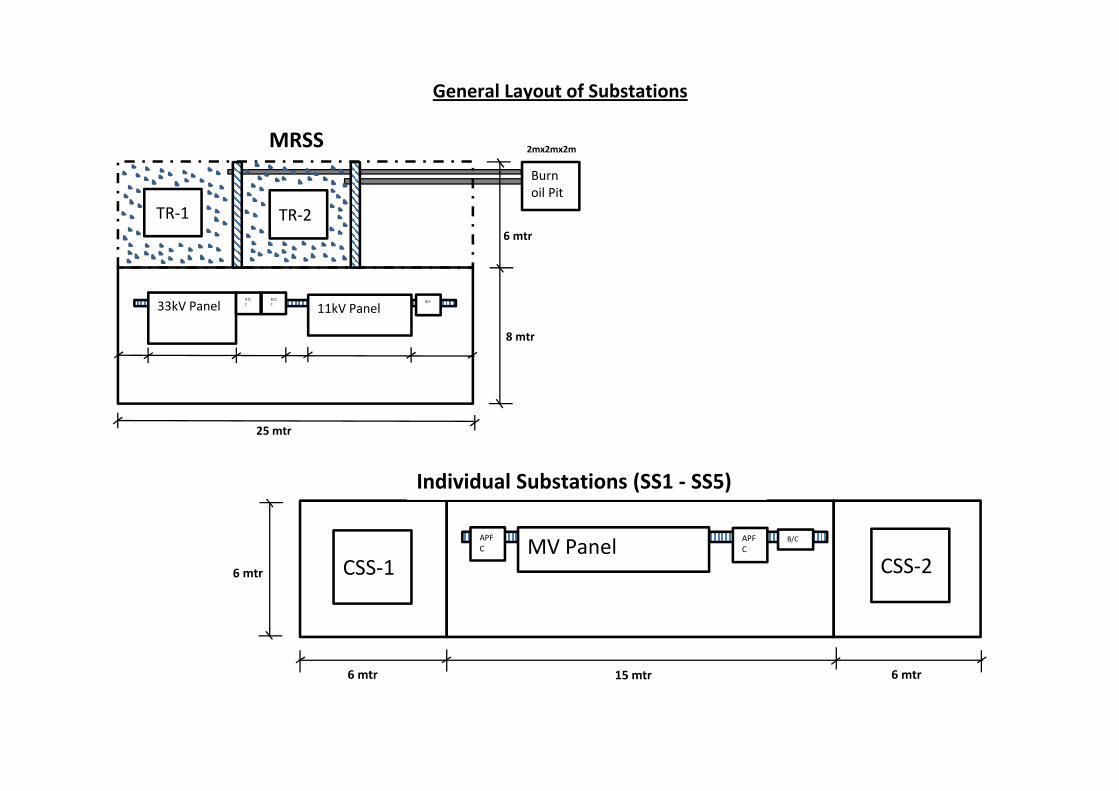
General Layout of Substations
6 mtr
8 mtr
25 mtr
TR‐1 TR‐2
33kV Panel 11kV PanelRTCC
RTCC
CSS‐1 CSS‐2MV Panel
APFC
B/C
MRSS
Individual Substations (SS1 ‐ SS5)
APFC
6 mtr
15 mtr 6 mtr6 mtr
B/C
Burn oil Pit
2mx2mx2m