Embed Size (px)
Citation preview
Technical specification
FLUXUS® F608**-F2
TSFLUXUS_F608xx-F2V2-1-3EN_Leu, 2017-05-23 1
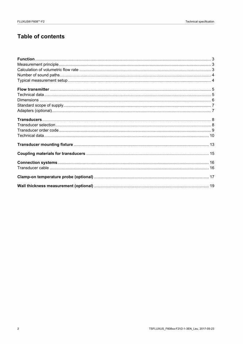
FLUXUS F608 supported by handle
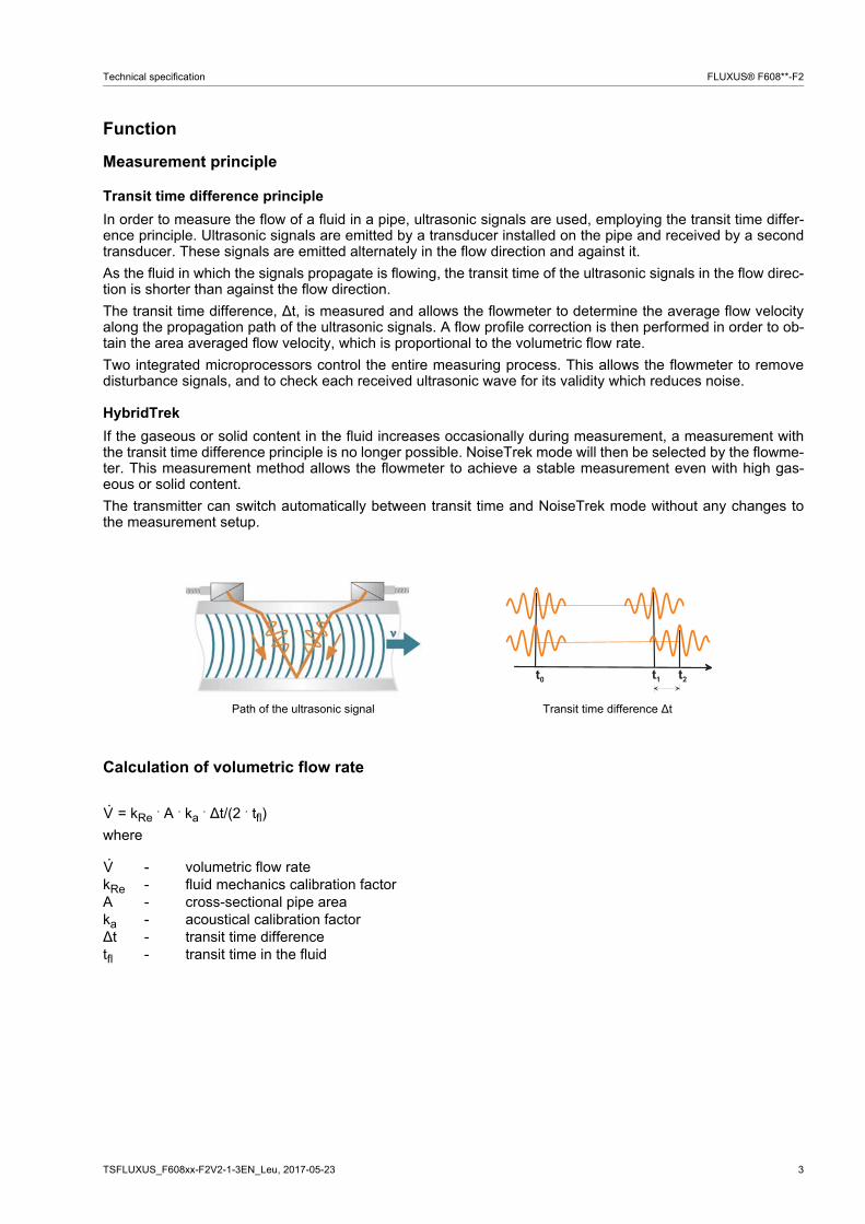
Measurement with transducers mounted with the portable Variofix VP
Measurement with the flow transmitter fixed to the pipe with the QuickFix pipe mounting fixture
FLUXUS F608
FLUXUS F608
Portable ultrasonic flow measurement of liquids in hazardous areas
Portable instrument for non-invasive, quick ultrasonic flow measurement with clamp-on technology for all types of piping
Features
• Precise bi-directional and highly dynamic flow measure-ment with the non-invasive clamp-on technology
• High precision at fast and slow flow rates, high tem-perature and zero point stability
• Portable, easy-to-use flow transmitter with 2 flow chan-nels, multiple inputs, an integrated data logger with a serial interface
• Extremely resistant carbon fiber housing
• Covered by FM Class I Div. 2 certification
• Compact and very lightweight, allowing the measuring system to be easily carried as personal luggage, e.g. for offshore visits
• Water tight; resistant against oil, many liquids and dirt
• Li-Ion battery provides up to 25 hours of measurement operation
• Automatic loading of calibration data and transducer detection for a fast and easy set-up (less than 5 min), providing precise and long-term stable results
• User-friendly design
• Transducers available for a wide range of inner pipe diameters and fluid temperatures (
• Rugged transducers (FM Class I Div. 2, resistant to rough environments and humidity)
• Robust, water-tight (IP67) transport case with compre-hensive accessories
• HybridTrek automatically switches between transit time and NoiseTrek mode of measurement when high partic-ulate flows are encountered
• QuickFix for fast mounting of the flow transmitter in diffi-cult conditions
• Measurement is unaffected by fluid density, viscosity and solid content (max. 10 % of volume)
Applications
Designed for the following industries:
• Upstream (on- and offshore)
• Midstream and downstream (pipelines and refineries)
• Chemical industry
• Energy sector (e.g. HVAC, geothermal, power plants)
-170...+600 °C)
FLUXUS® F608**-F2 Technical specification
Table of contents
TSFLUXUS_F608xx-F2V2-1-3EN_Leu, 2017-05-232
Function ........................................................................................................................................................... 3Measurement principle...................................................................................................................................... 3Calculation of volumetric flow rate .................................................................................................................... 3Number of sound paths..................................................................................................................................... 4Typical measurement setup .............................................................................................................................. 4
Flow transmitter .............................................................................................................................................. 5Technical data................................................................................................................................................... 5Dimensions ....................................................................................................................................................... 6Standard scope of supply.................................................................................................................................. 7Adapters (optional)............................................................................................................................................ 7
Transducers..................................................................................................................................................... 8Transducer selection......................................................................................................................................... 8Transducer order code...................................................................................................................................... 9Technical data................................................................................................................................................. 10
Transducer mounting fixture ....................................................................................................................... 13
Coupling materials for transducers ............................................................................................................ 15
Connection systems ..................................................................................................................................... 16Transducer cable ............................................................................................................................................ 16
Clamp-on temperature probe (optional) ..................................................................................................... 17
Wall thickness measurement (optional) ..................................................................................................... 19
TSFLUXUS_F608xx-F2V2-1-3EN_Leu, 2017-05-23 3
Technical specification FLUXUS® F608**-F2
Function
Measurement principle
Transit time difference principle
In order to measure the flow of a fluid in a pipe, ultrasonic signals are used, employing the transit time differ-ence principle. Ultrasonic signals are emitted by a transducer installed on the pipe and received by a secondtransducer. These signals are emitted alternately in the flow direction and against it.
As the fluid in which the signals propagate is flowing, the transit time of the ultrasonic signals in the flow direc-tion is shorter than against the flow direction.
The transit time difference, ∆t, is measured and allows the flowmeter to determine the average flow velocityalong the propagation path of the ultrasonic signals. A flow profile correction is then performed in order to ob-tain the area averaged flow velocity, which is proportional to the volumetric flow rate.
Two integrated microprocessors control the entire measuring process. This allows the flowmeter to removedisturbance signals, and to check each received ultrasonic wave for its validity which reduces noise.
HybridTrek
If the gaseous or solid content in the fluid increases occasionally during measurement, a measurement withthe transit time difference principle is no longer possible. NoiseTrek mode will then be selected by the flowme-ter. This measurement method allows the flowmeter to achieve a stable measurement even with high gas-eous or solid content.
The transmitter can switch automatically between transit time and NoiseTrek mode without any changes tothe measurement setup.
Calculation of volumetric flow rate
= kRe . A . ka . ∆t/(2 . tfl)
where
Path of the ultrasonic signal Transit time difference ∆t
- volumetric flow ratekRe - fluid mechanics calibration factorA - cross-sectional pipe areaka - acoustical calibration factor∆t - transit time differencetfl - transit time in the fluid
��
��
��
V·
V·
4 TSFLUXUS_F608xx-F2V2-1-3EN_Leu, 2017-05-23
FLUXUS® F608**-F2 Technical specification
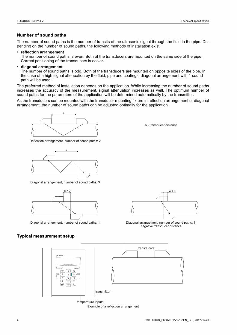
Number of sound paths
The number of sound paths is the number of transits of the ultrasonic signal through the fluid in the pipe. De-pending on the number of sound paths, the following methods of installation exist:
• reflection arrangementThe number of sound paths is even. Both of the transducers are mounted on the same side of the pipe. Correct positioning of the transducers is easier.
• diagonal arrangementThe number of sound paths is odd. Both of the transducers are mounted on opposite sides of the pipe. In the case of a high signal attenuation by the fluid, pipe and coatings, diagonal arrangement with 1 sound path will be used.
The preferred method of installation depends on the application. While increasing the number of sound pathsincreases the accuracy of the measurement, signal attenuation increases as well. The optimum number ofsound paths for the parameters of the application will be determined automatically by the transmitter.
As the transducers can be mounted with the transducer mounting fixture in reflection arrangement or diagonalarrangement, the number of sound paths can be adjusted optimally for the application..
Typical measurement setup
a - transducer distance
Reflection arrangement, number of sound paths: 2
Diagonal arrangement, number of sound paths: 3
Diagonal arrangement, number of sound paths: 1 Diagonal arrangement, number of sound paths: 1,negative transducer distance
Example of a reflection arrangement
a
a
a > 0 a < 0
� � � � � � � � � � � � � � � �
� ��
�
� ��
� � �
� � �
� � � �
� � � � � �� � � �
� � � � �
� � � � �
�� �
� � � � � � � � � � �
�� � � �
� � � � �
� ! � � �
� � � �
" � # " $ � � � � %
transducers
transmitter
temperature inputs
TSFLUXUS_F608xx-F2V2-1-3EN_Leu, 2017-05-23 5
Technical specification FLUXUS® F608**-F2
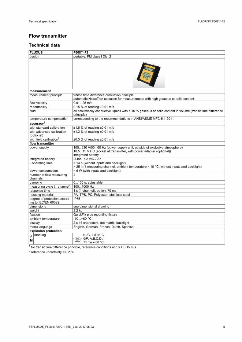
Flow transmitter
Technical data
FLUXUS F608**-F2design portable, FM class I Div. 2
measurementmeasurement principle transit time difference correlation principle,
automatic NoiseTrek selection for measurements with high gaseous or solid contentflow velocity 0.01...25 m/srepeatability 0.15 % of reading ±0.01 m/sfluid all acoustically conductive liquids with < 10 % gaseous or solid content in volume (transit time difference
principle)temperature compensation corresponding to the recommendations in ANSI/ASME MFC-5.1-2011
accuracy1
with standard calibration ±1.6 % of reading ±0.01 m/swith advanced calibration (optional)
±1.2 % of reading ±0.01 m/s
with field calibration2 ±0.5 % of reading ±0.01 m/sflow transmitterpower supply 100...230 V/50...60 Hz (power supply unit, outside of explosive atmosphere)
10.5...15 V DC (socket at transmitter, with power adapter (optional))integrated battery
integrated battery Li-Ion, 7.2 V/6.2 Ah- operating time > 14 h (without inputs and backlight)
> 25 h (1 measuring channel, ambient temperature > 10 °C, without inputs and backlight)power consumption < 6 W (with inputs and backlight)number of flow measuring channels
2
damping 0...100 s, adjustablemeasuring cycle (1 channel) 100...1000 Hzresponse time 1 s (1 channel), option: 70 mshousing material PA, TPS, PC, Polyester, stainless steeldegree of protection accord-ing to IEC/EN 60529
IP65
dimensions see dimensional drawingweight 2.2 kgfixation QuickFix pipe mounting fixtureambient temperature -10...+60 °Cdisplay 2 x 16 characters, dot matrix, backlightmenu language English, German, French, Dutch, Spanishexplosion protection
FM
marking NI/Cl. I /Div. 2/GP. A,B,C,D /T5 Ta = 60 °C
1 for transit time difference principle, reference conditions and v > 0.15 m/s2 reference uncertainty < 0.2 %
6 TSFLUXUS_F608xx-F2V2-1-3EN_Leu, 2017-05-23
FLUXUS® F608**-F2 Technical specification
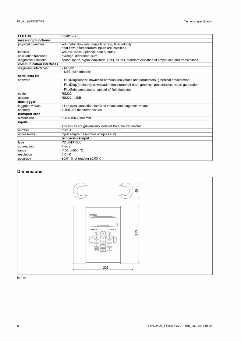
Dimensions
measuring functionsphysical quantities volumetric flow rate, mass flow rate, flow velocity,
heat flow (if temperature inputs are installed)totalizer volume, mass, optional: heat quantitycalculation functions average, difference, sumdiagnostic functions sound speed, signal amplitude, SNR, SCNR, standard deviation of amplitudes and transit timescommunication interfacesdiagnostic interfaces - RS232
- USB (with adapter)serial data kitsoftware - FluxDiagReader: download of measured values and parameters, graphical presentation
- FluxDiag (optional): download of measurement data, graphical presentation, report generation
- FluxSubstanceLoader: upload of fluid data setsсable RS232adapter RS232 - USBdata loggerloggable values all physical quantities, totalized values and diagnostic valuescapacity > 100 000 measured valuestransport casedimensions 500 x 400 x 190 mminputs
The inputs are galvanically isolated from the transmitter.number max. 4accessories input adapter (if number of inputs > 2)
temperature inputtype Pt100/Pt1000connection 4-wirerange -150...+560 °Cresolution 0.01 Kaccuracy ±0.01 % of reading ±0.03 K
in mm
FLUXUS F608**-F2
� � � � � � � � � � � � � � � �
� ��
�
� ��
� � �
� � �
� � � �
� � � � � �� � � �
� � � � �
� � � � �
�� �
� � � � � � � � � � �
�� � � �
� � � � �
� ! � � �
� � � �
" � # " $ � � � � %
226
5921
3
TSFLUXUS_F608xx-F2V2-1-3EN_Leu, 2017-05-23 7
Technical specification FLUXUS® F608**-F2
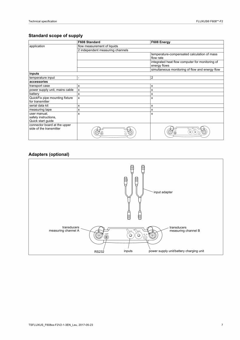
Standard scope of supply
Adapters (optional)
F608 Standard F608 Energyapplication flow measurement of liquids
2 independent measuring channelstemperature-compensated calculation of mass flow rateintegrated heat flow computer for monitoring of energy flowssimultaneous monitoring of flow and energy flow
inputstemperature input - 2accessoriestransport case x xpower supply unit, mains cable x xbattery x xQuickFix pipe mounting fixture for transmitter
x x
serial data kit x xmeasuring tape x xuser manual,safety instructions,Quick start guide
x x
connector board at the upper side of the transmitter
� � ! $ � � ! "
� � � � � � ! � ! � �
� � ! $ � � ! "
� � � �� � ! � ! � �
� & ' ( )
� � * � � � � * � �
� � ! $ � � ! "
� � � �� � ! � ! � �
� & ' ( )
� � * � � � � * � �
transducersmeasuring channel A
RS232 inputs
transducersmeasuring channel B
power supply unit/battery charging unit
input adapter
8 TSFLUXUS_F608xx-F2V2-1-3EN_Leu, 2017-05-23
FLUXUS® F608**-F2 Technical specification
Transducers
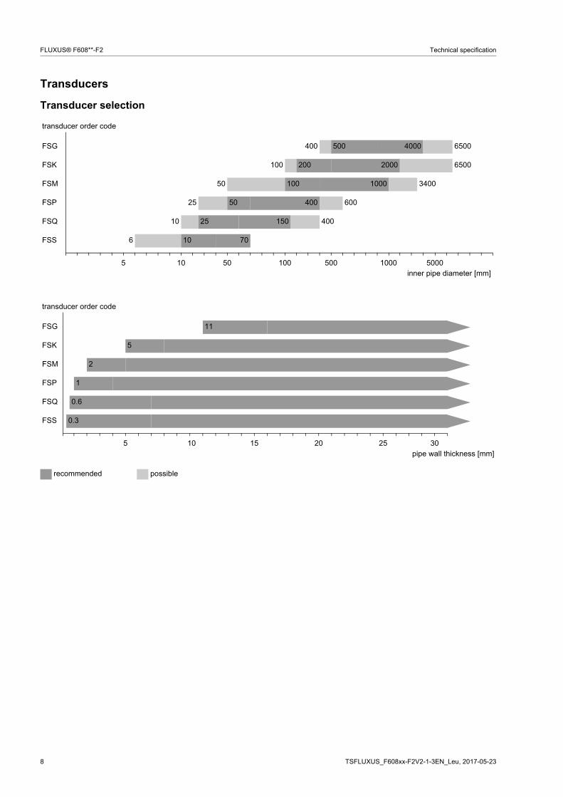
Transducer selection
transducer order code
FSG 400 500 4000 6500
FSK 100 200 2000 6500
FSM 50 100 1000 3400
FSP 25 50 400 600
FSQ 10 25 150 400
FSS 6 10 70
5 10 50 100 500 1000 5000inner pipe diameter [mm]
transducer order code
FSG 11
FSK 5
FSM 2
FSP 1
FSQ 0.6
FSS 0.3
5 10 15 20 25 30pipe wall thickness [mm]
recommended possible
TSFLUXUS_F608xx-F2V2-1-3EN_Leu, 2017-05-23 9
Technical specification FLUXUS® F608**-F2
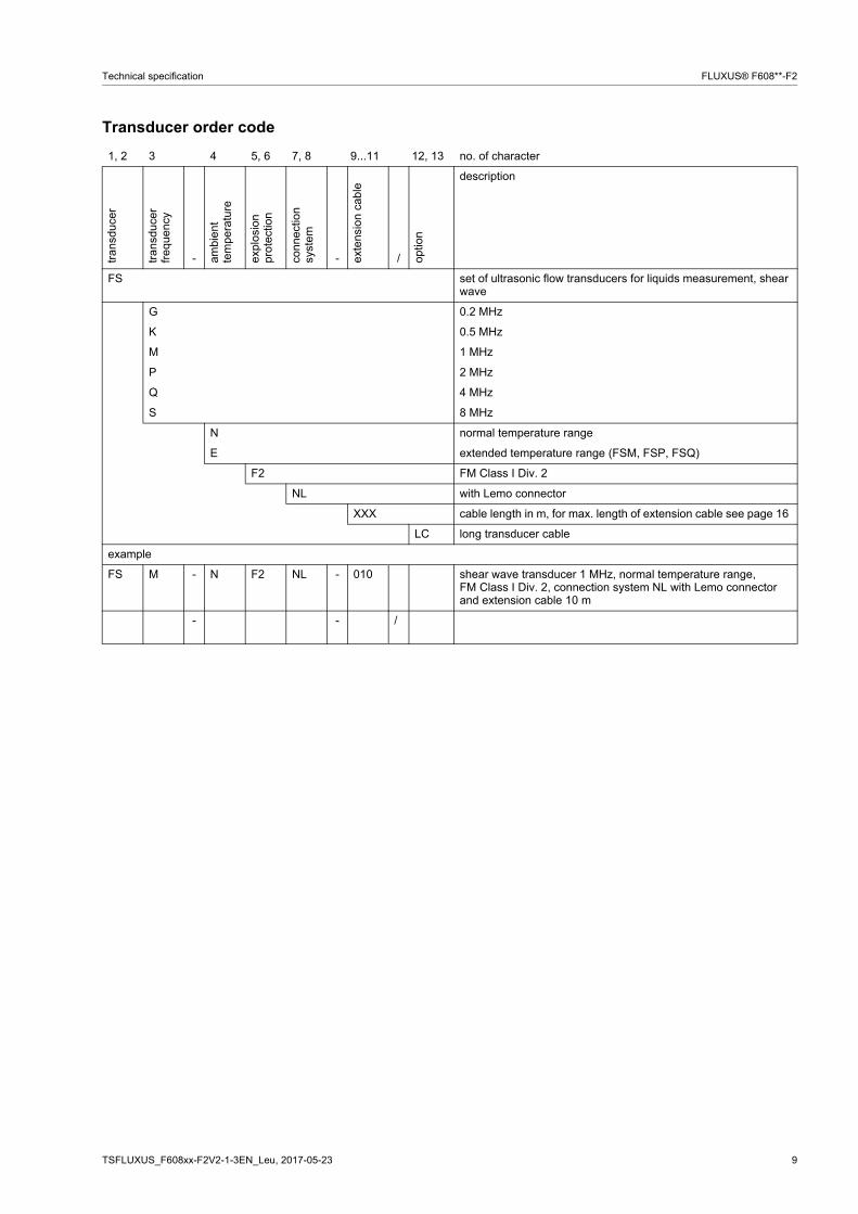
Transducer order code
1, 2 3 4 5, 6 7, 8 9...11 12, 13 no. of character
tra
nsdu
cer
tra
nsdu
cer
fre
quen
cy
- ambi
ent
tem
pera
ture
expl
osio
n pr
ote
ctio
n
conn
ectio
n sy
stem
- exte
nsio
n ca
ble
/ optio
n
description
FS set of ultrasonic flow transducers for liquids measurement, shear wave
G 0.2 MHz
K 0.5 MHz
M 1 MHz
P 2 MHz
Q 4 MHz
S 8 MHz
N normal temperature range
E extended temperature range (FSM, FSP, FSQ)
F2 FM Class I Div. 2
NL with Lemo connector
XXX cable length in m, for max. length of extension cable see page 16
LC long transducer cable
example
FS M - N F2 NL - 010 shear wave transducer 1 MHz, normal temperature range, FM Class I Div. 2, connection system NL with Lemo connector and extension cable 10 m
- - /
10 TSFLUXUS_F608xx-F2V2-1-3EN_Leu, 2017-05-23
FLUXUS® F608**-F2 Technical specification
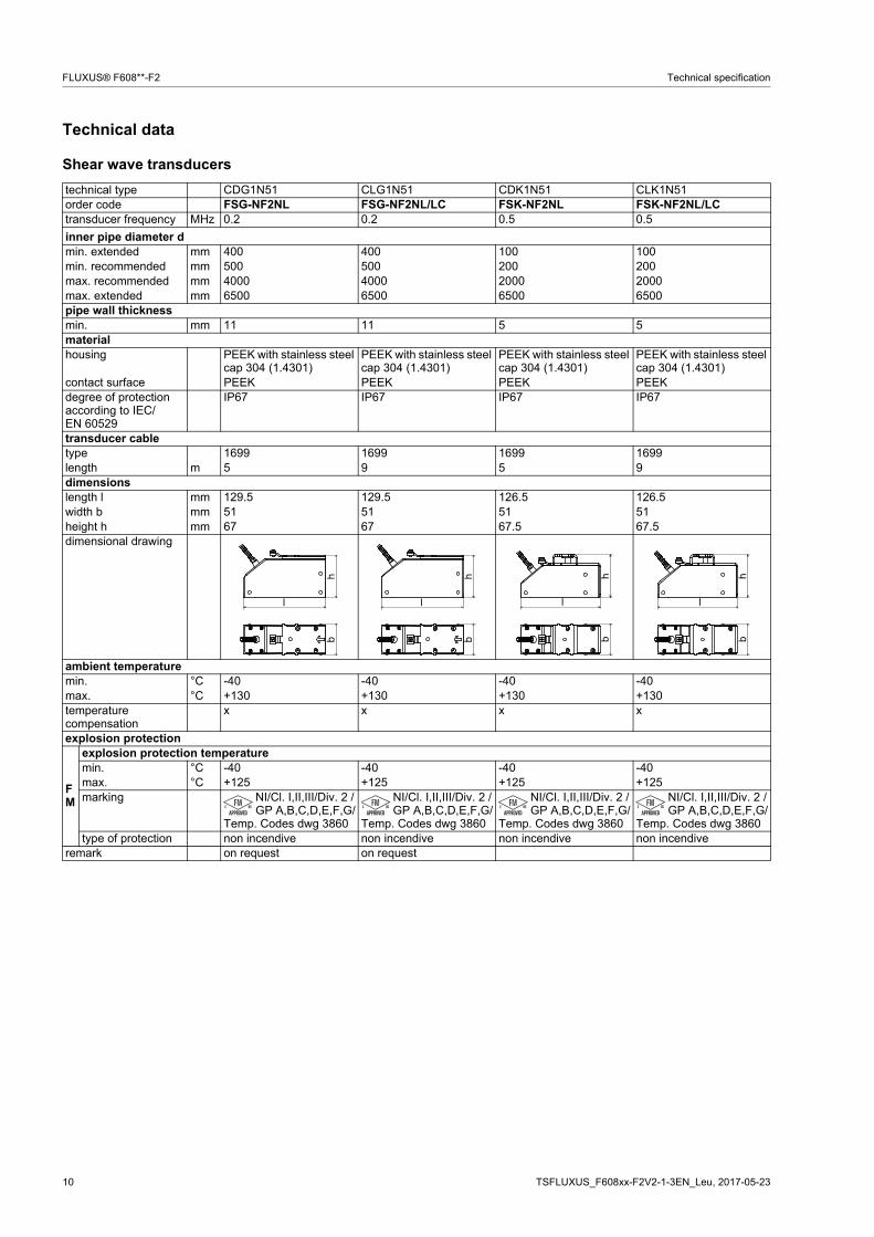
Technical data
Shear wave transducers
technical type CDG1N51 CLG1N51 CDK1N51 CLK1N51order code FSG-NF2NL FSG-NF2NL/LC FSK-NF2NL FSK-NF2NL/LCtransducer frequency MHz 0.2 0.2 0.5 0.5
inner pipe diameter dmin. extended mm 400 400 100 100min. recommended mm 500 500 200 200max. recommended mm 4000 4000 2000 2000max. extended mm 6500 6500 6500 6500pipe wall thicknessmin. mm 11 11 5 5materialhousing PEEK with stainless steel
cap 304 (1.4301)PEEK with stainless steel cap 304 (1.4301)
PEEK with stainless steel cap 304 (1.4301)
PEEK with stainless steel cap 304 (1.4301)
contact surface PEEK PEEK PEEK PEEKdegree of protection according to IEC/EN 60529
IP67 IP67 IP67 IP67
transducer cabletype 1699 1699 1699 1699length m 5 9 5 9dimensionslength l mm 129.5 129.5 126.5 126.5width b mm 51 51 51 51height h mm 67 67 67.5 67.5dimensional drawing
ambient temperaturemin. °C -40 -40 -40 -40max. °C +130 +130 +130 +130temperature compensation
x x x x
explosion protection
FM
explosion protection temperaturemin. °C -40 -40 -40 -40max. °C +125 +125 +125 +125marking NI/Cl. I,II,III/Div. 2 /
GP A,B,C,D,E,F,G/Temp. Codes dwg 3860
NI/Cl. I,II,III/Div. 2 /GP A,B,C,D,E,F,G/
Temp. Codes dwg 3860
NI/Cl. I,II,III/Div. 2 /GP A,B,C,D,E,F,G/
Temp. Codes dwg 3860
NI/Cl. I,II,III/Div. 2 /GP A,B,C,D,E,F,G/
Temp. Codes dwg 3860type of protection non incendive non incendive non incendive non incendive
remark on request on request
l
hb
l
hb
lh
bl
hb
TSFLUXUS_F608xx-F2V2-1-3EN_Leu, 2017-05-23 11
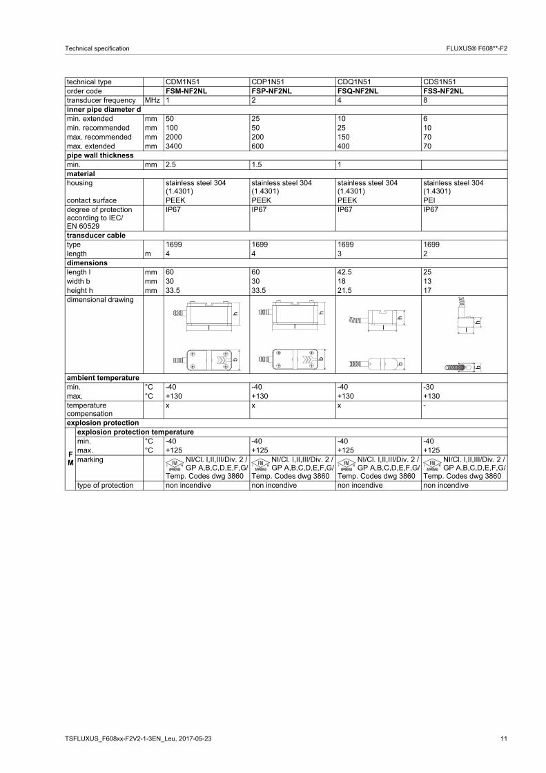
Technical specification FLUXUS® F608**-F2
technical type CDM1N51 CDP1N51 CDQ1N51 CDS1N51order code FSM-NF2NL FSP-NF2NL FSQ-NF2NL FSS-NF2NLtransducer frequency MHz 1 2 4 8inner pipe diameter dmin. extended mm 50 25 10 6min. recommended mm 100 50 25 10max. recommended mm 2000 200 150 70max. extended mm 3400 600 400 70pipe wall thicknessmin. mm 2.5 1.5 1materialhousing stainless steel 304
(1.4301)stainless steel 304 (1.4301)
stainless steel 304 (1.4301)
stainless steel 304 (1.4301)
contact surface PEEK PEEK PEEK PEIdegree of protection according to IEC/EN 60529
IP67 IP67 IP67 IP67
transducer cabletype 1699 1699 1699 1699length m 4 4 3 2dimensionslength l mm 60 60 42.5 25width b mm 30 30 18 13height h mm 33.5 33.5 21.5 17dimensional drawing
ambient temperaturemin. °C -40 -40 -40 -30max. °C +130 +130 +130 +130temperature compensation
x x x -
explosion protection
FM
explosion protection temperaturemin. °C -40 -40 -40 -40max. °C +125 +125 +125 +125marking NI/Cl. I,II,III/Div. 2 /
GP A,B,C,D,E,F,G/Temp. Codes dwg 3860
NI/Cl. I,II,III/Div. 2 /GP A,B,C,D,E,F,G/
Temp. Codes dwg 3860
NI/Cl. I,II,III/Div. 2 /GP A,B,C,D,E,F,G/
Temp. Codes dwg 3860
NI/Cl. I,II,III/Div. 2 /GP A,B,C,D,E,F,G/
Temp. Codes dwg 3860type of protection non incendive non incendive non incendive non incendive
hb
lh
bl
hb
l
hb
l
12 TSFLUXUS_F608xx-F2V2-1-3EN_Leu, 2017-05-23
FLUXUS® F608**-F2 Technical specification
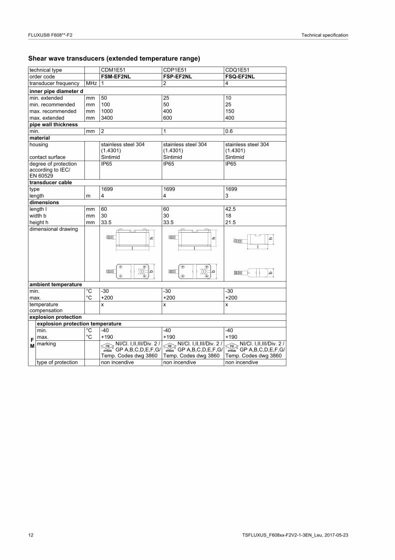
Shear wave transducers (extended temperature range)
technical type CDM1E51 CDP1E51 CDQ1E51order code FSM-EF2NL FSP-EF2NL FSQ-EF2NLtransducer frequency MHz 1 2 4
inner pipe diameter dmin. extended mm 50 25 10min. recommended mm 100 50 25max. recommended mm 1000 400 150max. extended mm 3400 600 400pipe wall thicknessmin. mm 2 1 0.6materialhousing stainless steel 304
(1.4301)stainless steel 304 (1.4301)
stainless steel 304 (1.4301)
contact surface Sintimid Sintimid Sintimiddegree of protection according to IEC/EN 60529
IP65 IP65 IP65
transducer cabletype 1699 1699 1699length m 4 4 3dimensionslength l mm 60 60 42.5width b mm 30 30 18height h mm 33.5 33.5 21.5dimensional drawing
ambient temperaturemin. °C -30 -30 -30max. °C +200 +200 +200temperature compensation
x x x
explosion protection
FM
explosion protection temperaturemin. °C -40 -40 -40max. °C +190 +190 +190marking NI/Cl. I,II,III/Div. 2 /
GP A,B,C,D,E,F,G/Temp. Codes dwg 3860
NI/Cl. I,II,III/Div. 2 /GP A,B,C,D,E,F,G/
Temp. Codes dwg 3860
NI/Cl. I,II,III/Div. 2 /GP A,B,C,D,E,F,G/
Temp. Codes dwg 3860type of protection non incendive non incendive non incendive
hb
l
hb
l
hb
l
TSFLUXUS_F608xx-F2V2-1-3EN_Leu, 2017-05-23 13
Technical specification FLUXUS® F608**-F2
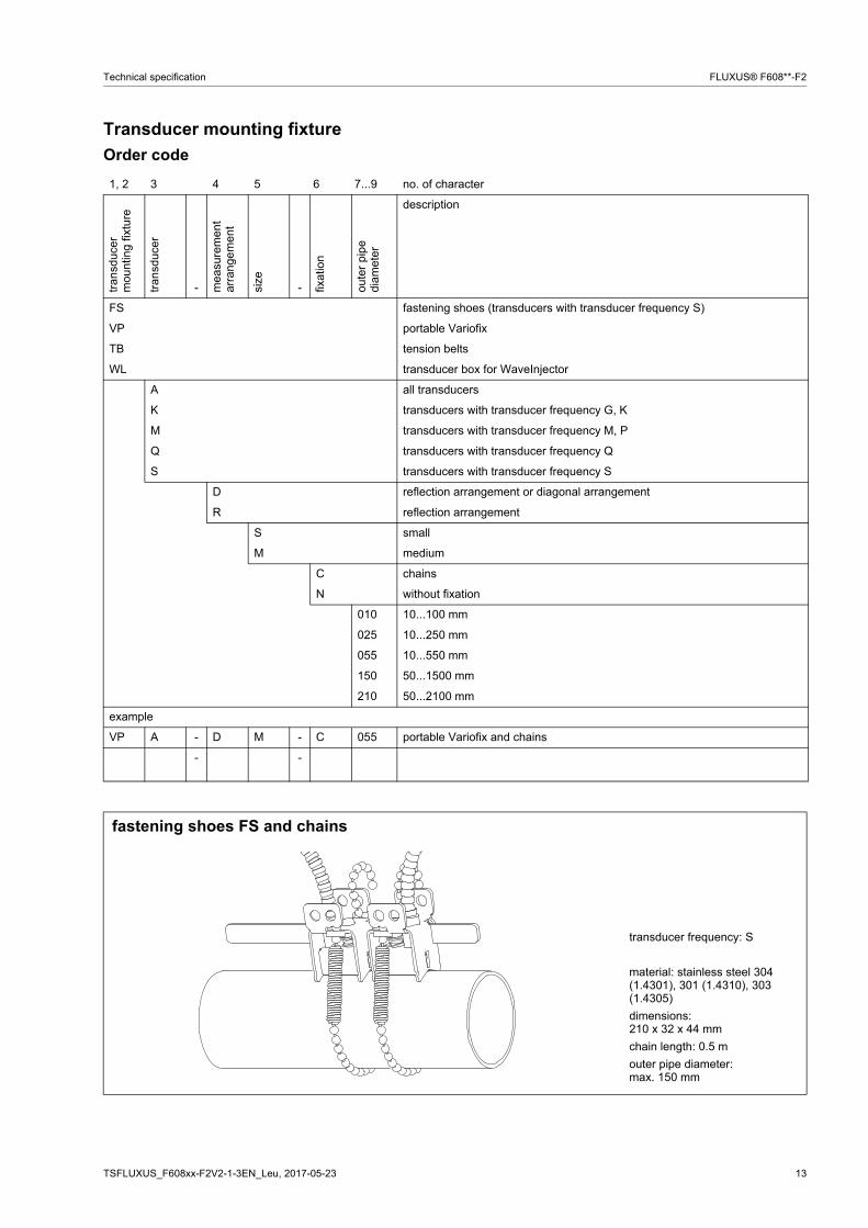
Transducer mounting fixture
Order code
1, 2 3 4 5 6 7...9 no. of character
tran
sduc
er
mou
ntin
g fix
ture
tran
sduc
er
- mea
sure
men
t ar
rang
emen
t
size
- fixat
ion
oute
r pi
pe
diam
eter
description
FS fastening shoes (transducers with transducer frequency S)
VP portable Variofix
TB tension belts
WL transducer box for WaveInjector
A all transducers
K transducers with transducer frequency G, K
M transducers with transducer frequency M, P
Q transducers with transducer frequency Q
S transducers with transducer frequency S
D reflection arrangement or diagonal arrangement
R reflection arrangement
S small
M medium
C chains
N without fixation
010 10...100 mm
025 10...250 mm
055 10...550 mm
150 50...1500 mm
210 50...2100 mm
example
VP A - D M - C 055 portable Variofix and chains
- -
fastening shoes FS and chains
transducer frequency: S
material: stainless steel 304 (1.4301), 301 (1.4310), 303 (1.4305)
dimensions:210 x 32 x 44 mm
chain length: 0.5 m
outer pipe diameter: max. 150 mm
14 TSFLUXUS_F608xx-F2V2-1-3EN_Leu, 2017-05-23
FLUXUS® F608**-F2 Technical specification
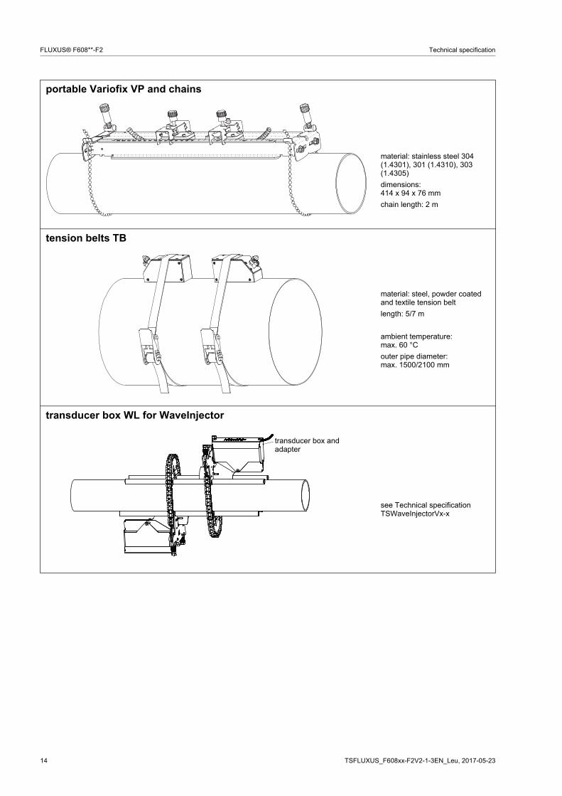
portable Variofix VP and chains
material: stainless steel 304 (1.4301), 301 (1.4310), 303 (1.4305)
dimensions:414 x 94 x 76 mm
chain length: 2 m
tension belts TB
material: steel, powder coated and textile tension belt
length: 5/7 m
ambient temperature:max. 60 °C
outer pipe diameter:max. 1500/2100 mm
transducer box WL for WaveInjector
see Technical specificationTSWaveInjectorVx-x
transducer box and adapter
TSFLUXUS_F608xx-F2V2-1-3EN_Leu, 2017-05-23 15
Technical specification FLUXUS® F608**-F2
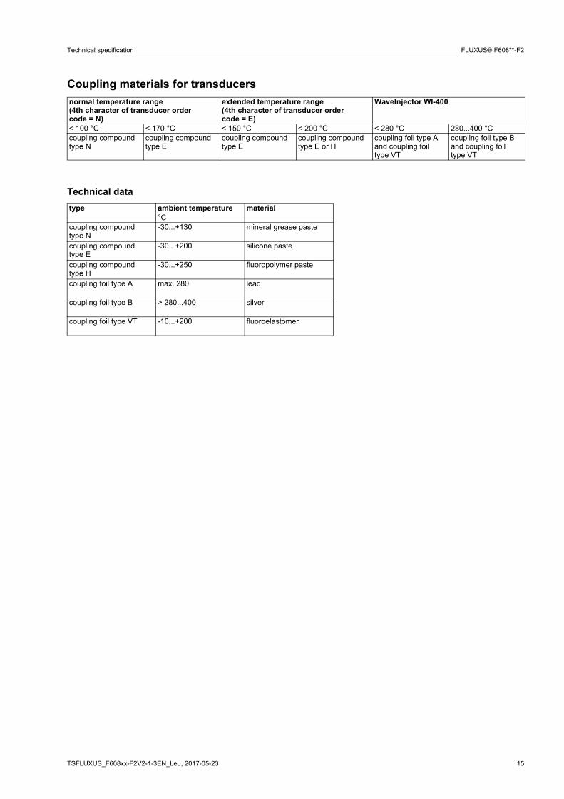
Coupling materials for transducers
Technical data
normal temperature range(4th character of transducer order code = N)
extended temperature range(4th character of transducer order code = E)
WaveInjector WI-400
< 100 °C < 170 °C < 150 °C < 200 °C < 280 °C 280...400 °Ccoupling compound type N
coupling compound type E
coupling compound type E
coupling compoundtype E or H
coupling foil type A and coupling foil type VT
coupling foil type B and coupling foil type VT
type ambient temperature material°C
coupling compound type N
-30...+130 mineral grease paste
coupling compound type E
-30...+200 silicone paste
coupling compound type H
-30...+250 fluoropolymer paste
coupling foil type A max. 280 lead
coupling foil type B > 280...400 silver
coupling foil type VT -10...+200 fluoroelastomer
16 TSFLUXUS_F608xx-F2V2-1-3EN_Leu, 2017-05-23
FLUXUS® F608**-F2 Technical specification
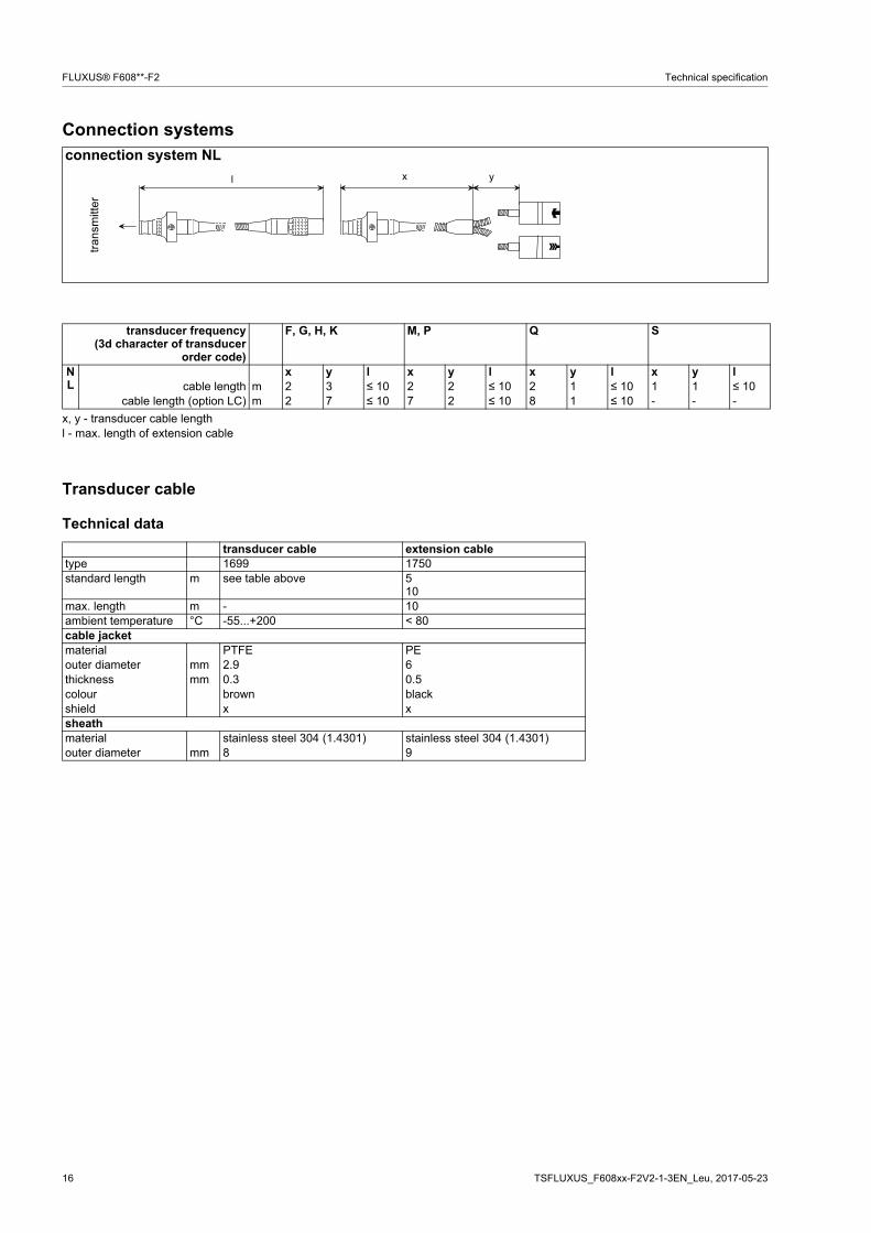
Connection systems
Transducer cable
Technical data
connection system NL
transducer frequency(3d character of transducer
order code)
F, G, H, K M, P Q S
NL
x y l x y l x y l x y lcable length m 2 3 ≤ 10 2 2 ≤ 10 2 1 ≤ 10 1 1 ≤ 10
cable length (option LC) m 2 7 ≤ 10 7 2 ≤ 10 8 1 ≤ 10 - - -
x, y - transducer cable lengthl - max. length of extension cable
transducer cable extension cabletype 1699 1750standard length m see table above 5
10max. length m - 10ambient temperature °C -55...+200 < 80cable jacketmaterial PTFE PEouter diameter mm 2.9 6thickness mm 0.3 0.5colour brown blackshield x xsheathmaterial stainless steel 304 (1.4301) stainless steel 304 (1.4301)outer diameter mm 8 9
tran
smitt
er
x yl
TSFLUXUS_F608xx-F2V2-1-3EN_Leu, 2017-05-23 17
Technical specification FLUXUS® F608**-F2
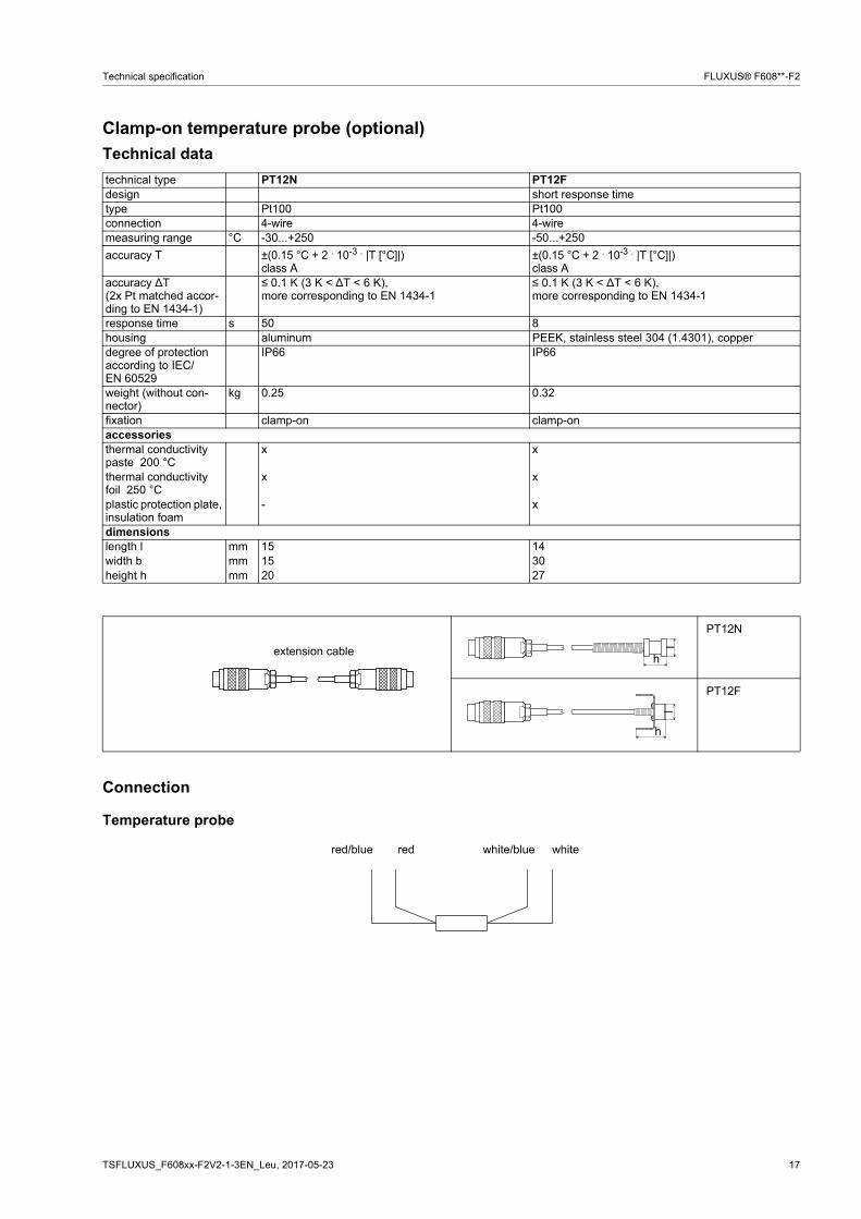
Clamp-on temperature probe (optional)
Technical data
Connection
Temperature probe
technical type PT12N PT12Fdesign short response timetype Pt100 Pt100connection 4-wire 4-wiremeasuring range °C -30...+250 -50...+250
accuracy T ±(0.15 °C + 2 . 10-3 . |T [°C]|)class A
±(0.15 °C + 2 . 10-3 . |T [°C]|)class A
accuracy ∆T(2x Pt matched accor-ding to EN 1434-1)
≤ 0.1 K (3 K < ∆T < 6 K), more corresponding to EN 1434-1
≤ 0.1 K (3 K < ∆T < 6 K), more corresponding to EN 1434-1
response time s 50 8housing aluminum PEEK, stainless steel 304 (1.4301), copperdegree of protection according to IEC/EN 60529
IP66 IP66
weight (without con-nector)
kg 0.25 0.32
fixation clamp-on clamp-onaccessoriesthermal conductivity paste 200 °C
x x
thermal conductivity foil 250 °C
x x
plastic protection plate, insulation foam
- x
dimensionslength l mm 15 14width b mm 15 30height h mm 20 27
PT12N
PT12F
extension cableh
l
h
l
red/blue red white/blue white
18 TSFLUXUS_F608xx-F2V2-1-3EN_Leu, 2017-05-23
FLUXUS® F608**-F2 Technical specification
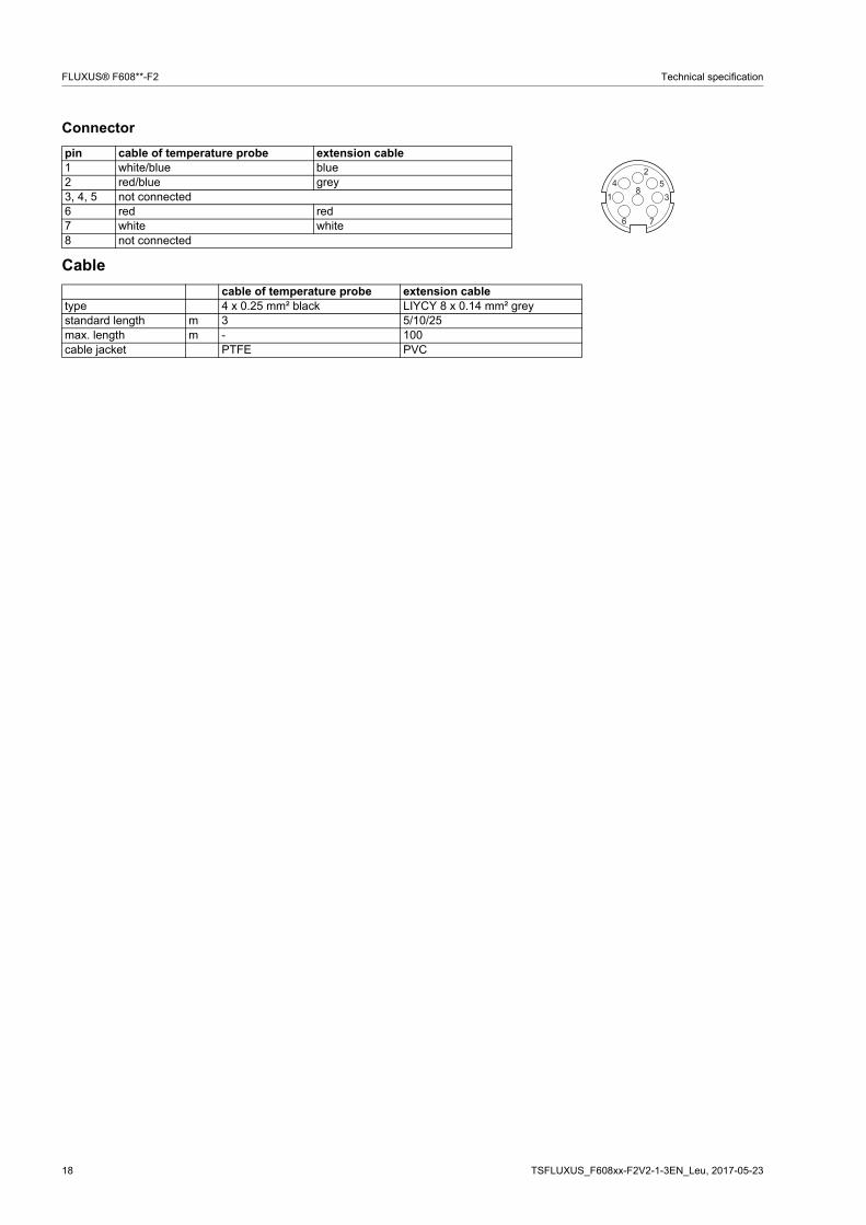
Connector
Cable
pin cable of temperature probe extension cable1 white/blue blue2 red/blue grey3, 4, 5 not connected6 red red7 white white8 not connected
cable of temperature probe extension cabletype 4 x 0.25 mm² black LIYCY 8 x 0.14 mm² greystandard length m 3 5/10/25max. length m - 100cable jacket PTFE PVC
�
�
�
� �
�
TSFLUXUS_F608xx-F2V2-1-3EN_Leu, 2017-05-23 19
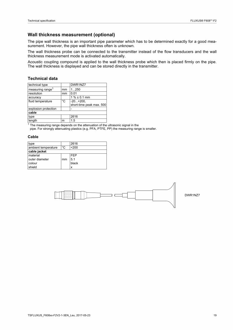
Technical specification FLUXUS® F608**-F2
Wall thickness measurement (optional)The pipe wall thickness is an important pipe parameter which has to be determined exactly for a good mea-surement. However, the pipe wall thickness often is unknown.
The wall thickness probe can be connected to the transmitter instead of the flow transducers and the wallthickness measurement mode is activated automatically.
Acoustic coupling compound is applied to the wall thickness probe which then is placed firmly on the pipe.The wall thickness is displayed and can be stored directly in the transmitter.
Technical data
Cable
technical type DWR1NZ7
measuring range1 mm 1...250resolution mm 0.01accuracy 1 % ± 0.1 mmfluid temperature °C -20...+200,
short-time peak max. 500explosion protection -сabletype 2616length m 1.5
1 The measuring range depends on the attenuation of the ultrasonic signal in thepipe. For strongly attenuating plastics (e.g. PFA, PTFE, PP) the measuring range is smaller.
type 2616ambient temperature °C <200cable jacketmaterial FEPouter diameter mm 5.1colour blackshield x
DWR1NZ7

20 TSFLUXUS_F608xx-F2V2-1-3EN_Leu, 2017-05-23
FLUXUS® F608**-F2 Technical specification
FLEXIM GmbH
Wolfener Str. 36
12681 Berlin
Germany
Tel.: +49 (30) 93 66 76 60
Fax: +49 (30) 93 66 76 80
internet: www.flexim.com
e-mail: [email protected]
Subject to change without notification. Errors excepted.
FLUXUS® is a registered trademark of FLEXIM GmbH.