Embed Size (px)
Citation preview
Ver. 04, Aug/30/2013 Page: 1/17
Copyright 2010, National Synchrotron Radiation Research Center (NSRRC). This document is the property of NSRRC. No exploitation or transfer of any information contained herein is permitted in the absence of an agreement with NSRRC, and neither the document nor any such information may be released without the written consent of NSRRC.
TECHNICAL SPECIFICATION
BEAMLINE LIQUID-NITROGEN TRANSFER SYSTEM FOR TPS PROPECT
NATIONAL SYNCHROTRON RADIATION RESEARCH CENTER
Version 04 30th August, 2013

Ver. 04, Aug/30/2013 Page: 2/17
Copyright 2010, National Synchrotron Radiation Research Center (NSRRC). This document is the property of NSRRC. No exploitation or transfer of any information contained herein is permitted in the absence of an agreement with NSRRC, and neither the document nor any such information may be released without the written consent of NSRRC.
CONTENTS
1. INTRODUCTION ........................................................................................................ 3
2. SCOPE OF WORK ...................................................................................................... 3
3. APPLICATION CODES AND STANDARDS ........................................................... 4
4. BID PRICE .................................................................................................................... 5
5. MANUFACTURE AND PERFORMANCE REQUIREMENTS ............................ 5
6. TESTING AND INSPECTION ................................................................................... 8
7. PROJECT SCHEDULE AND REVIEW MEETING ............................................... 9
8. QUALITY CONTROL ................................................................................................ 9
9. TRANSPORT .............................................................................................................. 10
10. ACCEPTANCE ......................................................................................................... 10
11. DOCUMENTATION ................................................................................................ 11
LIST OF FIGURES 2CR-1-LN2-LAY001-01 Layout of Beam Line LN2 Transfer System
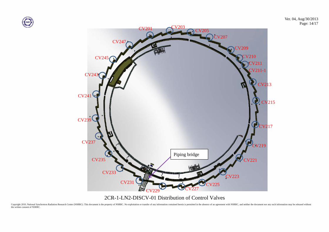
2CR-1-LN2-DISCV-01 Distribution of Control Valves
2CR-1-LN2-BLPFD-01 PFD and Scope of Supply for Beam Line LN2 Transfer System
2CR-1-LN2-TLROUT-01 Piping Route of LN2-TL1 and LN2-TL2
2CR-1-LN2-BLROUT-01 Piping Route of Branch Lines

Ver. 04, Aug/30/2013 Page: 3/17
Copyright 2010, National Synchrotron Radiation Research Center (NSRRC). This document is the property of NSRRC. No exploitation or transfer of any information contained herein is permitted in the absence of an agreement with NSRRC, and neither the document nor any such information may be released without the written consent of NSRRC.
1. INTRODUCTION This specification describes the NSRRC requirements for design, manufacture and inspection of the
beamline liquid-nitrogen (LN2) transfer system.
Taiwan Photon Source (TPS) at National Synchrotron Radiation Research Center (NSRRC) Hsinchu,
Taiwan, requires one (1) liquid-nitrogen (LN2) transfer line and twenty-six (26) branch lines with
twenty-six (26) control valves for the beamline (herein named as BL LN2 transfer system). Figure
2CR-1-LN2-LAY001-01 shows the layout of the BL LN2 transfer system. The BL LN2 transfer system is
composed of two separate lines LN2-TL1 and LN2-TL2, which connect to the main transfer line LN2-TL
through two cryogenic valves CV004 and CV005, respectively. The main transfer line, which connects
the LN2 storage tank at the source side and the phase separator of volume 1000 L at upstream of the
manifold for the cryogenic system and the SRF cryomodule, is now under construction and will be
completed in year 2013. There will be 24 beamlines constructed eventually, and each beamline requires
an independent LN2 supply. In total, 26 control valves are required to isolate the 26 branch lines. Because
of space constraints, the branch line can be located only on the elbow for the beamline. Figure
2CR-1-LN2-DISCV-01 shows the Distribution of the Control Valves. Control valves CV210 and
CV211-1 are to retain the possibility for LN2-TL1 and LN2-TL2 to be a backup of each other. The
capacity of the LN2 storage tank is 60 m3 with maximum operating pressure 6.0 barg. The required
consumption of LN2 for each beam line is 30 L/h.
To verify the integrated performance, the heat load of the BL LN2 transfer system should be
measured experimentally after installation on site by an evaporation approach. The calculated heat load
shall be better than 960 W. The measured integrated heat load shall be less than 1010 W. The defective
purchase with a price decrease shall be assessed at an amount to be calculated on the basis of 1 per cent of
the total Contract Price for each one watt (1 W) increase of the required performance (1010 W). For
instance, a total measured heat load 1020 W shall result in a price decrease 10 per cent of the total
Contract Price. If the measurement of the heat load exceeds 1060 W, the Contract shall be terminated for
default.
2. SCOPE OF WORK The Vendor is required to provide the following services:
(1) design and drawings of the BL LN2 transfer system;
(2) manufacturing file for the BL LN2 transfer system;
(3) manufacture of the BL LN2 transfer system;
(4) design and manufacture of all tools necessary for assembly, inspection, testing and transport of the BL
LN2 transfer system;
(5) installation and welding of the BL LN2 transfer system on site;
(6) all the piping support for installing the BL LN2 transfer system on site;
(7) all tests and test reports defined in Chapters 5 and 6;
(8) all documents defined in Chapter 11, and

Ver. 04, Aug/30/2013 Page: 4/17
Copyright 2010, National Synchrotron Radiation Research Center (NSRRC). This document is the property of NSRRC. No exploitation or transfer of any information contained herein is permitted in the absence of an agreement with NSRRC, and neither the document nor any such information may be released without the written consent of NSRRC.
(9) packing and DDU to the NSRRC jobsite at Hsinchu, Taiwan: all banking charges, including the inland
transit cost to the NSRRC job site, unloading costs, and other charges, as well as the costs of
conducting customs formalities payable upon import of the goods, are for the Vendor's account.
3. APPLICATION CODES AND STANDARDS (1) It is the Vendor's responsibility that the BL LN2 transfer system meets all laws, regulations and
standards of good practice commonly accepted in the cryogenic industry in Taiwan. NSRRC will
apply for the operating license of the BL LN2 transfer system, and the Vendor shall be fully
responsible to provide the necessary certified documentation for the license application including
(i) list with Tag numbers and description of instrument for the BL LN2 transfer system (3 copies),
(ii) ISO-metrics as built of the LN2 transfer line and a general arrangement drawing as built for the
LN2 keep full (3 copies),
(iii) structure drawing of the LN2 keep full device (3 copies),
(iv) strength calculation to prove that the chosen dimensions of the BL LN2 transfer system are within
the acceptable range for the design pressure (3 copies),
(v) certification documentation for the examination of the high-pressure vessel (original and certified
copy),
(vi) list and quantity of safety relief valves (3 copies),
(vii) specifications and drawings of safety relief valves (3 copies),
(viii) report of the calculation of safety relief valves blow-off capacity (3 copies),
(ix) certification documentation for the examination of the relief valve (original and certified copy),
(x) and other necessary documentation requested by the authority for license application.
(2) The license will be applied for after the contract is signed. In particular, this BL LN2 transfer system
should be designed in accordance with, or with reference to the, following documents:
(i) ASME Boiler and Pressure Vessel Code—Section II (Material Specification), Section V
(Nondestructive Examination), VIII, Division I (Unfired Pressure Vessels) and IX (Welding and
Brazing Qualifications), or PED code—H/H1 as a minimum;
(ii) ASME B31.3-1996 (Process Piping), B31.5-1987 (Code for Refrigeration Piping), and B36.1985
(Stainless-steel Pipe);
(iii) The pressure vessel should be certified with an ASME "U" Stamp, or PED "CE" marking.
(iv) The Vendor should be certified according a Welding Quality Code such as ISO 3834-2, or AWS
STD D1.1 (Structural Steel Welding);
(v) NIST for Helium;
(vi) NIST for Nitrogen;
(vii) OSHA (Occupational Safety and Health Act) or approved European equivalent standards;
(viii) IEEE Electrical Standard;
(ix) NFPA (National Fire Protection Association): NFPA 70, or approved European equivalent
Ver. 04, Aug/30/2013 Page: 5/17
Copyright 2010, National Synchrotron Radiation Research Center (NSRRC). This document is the property of NSRRC. No exploitation or transfer of any information contained herein is permitted in the absence of an agreement with NSRRC, and neither the document nor any such information may be released without the written consent of NSRRC.
standards, and
(x) CGA (Compressed Gas Association): CGA Pamphlet S-1.2, CGA Pamphlet S-1.3 or approved
European equivalent standards.
4. BID PRICE (1) The bid price shall be based on the requirements of this Technical Specification. Deviation from the
requirements of this Technical Specification is not allowed.
(2) The Vendor shall provide a cost breakdown list that includes the costs of each of the following items:
the LN2 transfer line, control valves (including pressure-relief safety valves), packing, shipment,
piping, installation, acceptance test, and payment to vendor’s staff for onsite work.
5. MANUFACTURE AND PERFORMANCE REQUIREMENTS The requirements of the major components of the BL LN2 transfer system are described in Section 5.1
Performance requirements. Moreover, the Vendor shall provide
(1) all cold and warm interconnecting piping between all skids and modules, referred to Figure
2CR-1-LN2-BLPFD-01; suitable conduit or tray shall be included if necessary;
(2) all valves to achieve the desired functions, referred to Figure 2CR-1-LN2-BLPFD-01;
(3) all sensors and mechanical gauges for monitoring of the operation of the BL LN2 transfer system,
referred to Figure 2CR-1-LN2-PFD001-01.
5.1 Performance requirements
(1) All process piping should be high-quality seamless stainless-steel piping.
(2) All vacuum jacket line should be welded stainless-steel piping according to ASTM A312/A999 with
inspection certificate 3.1B.
(3) All process piping should be constructed of 304L-type stainless steel. All vacuum-jacket piping
should be constructed of 316L-type stainless steel.
(4) The wall thickness of all process piping and vacuum jacket piping should be in accord with schedule
10S or more.
(5) All nitrogen process piping should be polished on the interior side. The polished piping should have a
surface with roughness less than 0.5 m and waviness less than 3 m (Ra<0.5 m, Ry<3 m,
Rz<3 m, RMS value).
(6) All welding shall be performed using the TIG method protected with argon gas (provide by vendor);
100 per cent penetration is required for butt welds. The Vendor should provide the WPS (Welding
Procedure Specification) in the Detailed Design Review Meeting for approval.
(7) All piping shall be degreased, clean and dry.
(8) The BL LN2 transfer system will be operated in an earthquake area. The LN2 transfer line should be
designed and installed to withstand lateral accelerations up to 0.7 g (6.86 m/s2).

Ver. 04, Aug/30/2013 Page: 6/17
Copyright 2010, National Synchrotron Radiation Research Center (NSRRC). This document is the property of NSRRC. No exploitation or transfer of any information contained herein is permitted in the absence of an agreement with NSRRC, and neither the document nor any such information may be released without the written consent of NSRRC.
(9) Safety devices are required for the process piping. The full-capacity safety pressure-relief valves
shall be installed as per Figure 2CR-1-LN2-BLPFD-01. The relief valves shall have their inlets
protected from blockage by suitably placed and secured screens.
(10) Temperature transmitters are required as indicated in Figure 2CR-1-LN2-PFD001-01. The cryogenic
linear temperature sensor (CLTS) of type CLTS-2B from VISHAY MICROMEASURES and the
pressure transmitter of type PAA-21 S PRO from KELLER should be implemented. Two temperature
sensors with one spare are required at each measurement point.
(11) The design pressure of the BL LN2 transfer system shall exceed 10 bar gauge pressure.
(12) The interface of the transfer line to the CV004 and CV005 should be a female vacuum-jacket bayonet
that will be delivered by NSRRC as per Figure 2CR-1-LN2-BLPFD-01.
(13) The layout for the BL LN2 transfer system is indicated in Figure 2CR-1-LN2-LAY001-01.
(14) The center line of the BL LN2 transfer line shall be 3260-mm away to the ground and 210-mm away
to the shielding wall.
(15) The spool length of the LN2 transfer line shall be within 10 m as per Figure 2CR-1-LN2-
TLROUT-01 and 2CR-1-LN2-BLROUT-01. Each section shall have single vacuum insulation and a
field joint is installed between the adjacent sections. A field joint shall be designed to accommodate 3
per cent uncertainty of the piping route specified in Figure 2CR-1-LN2-TLROUT-01 during welding
on site.
(16) The diameter of process line LN2-TL1-DN32-PN10 and LN2-TL2-DN32-PN10 shall be DN32
nominal bore size. The diameter of branch process line shall be DN15 nominal bore size.
(17) The piping route and the quotation of the BL LN2 transfer system shall be based on Figures 2CR-1-
LN2-TLROUT-01 and 2CR-1-LN2-BLROUT-01. The vendor shall survey the piping length and
angle on site. No additional piping cost shall be charged providing that the piping length is within 3
per cent of the uncertainty of the piping route specified in Figures 2CR-1-LN2-TLROUT-01 and
2CR-1-LN2-BLROUT-01.
(18) The BL LN2 transfer system should have twenty-six branches for supply of liquid nitrogen to the
beamlines as per Figures 2CR-1-LN2-BLPFD-01 and 2CR-1-LN2-TLROUT-01. One cryogenic
control valve is required at each set of branch line.
(19) The connection pipeline to the gas vent shall be above the LN2-TL1 and LN2-TL2. The diameter of
the gas vent shall be within 300 mm. The highest point of the gas vent shall be within 500 mm of the
center line of the LN2-TL1 and LN2-TL2.
(20) The pressure drop of the nitrogen process line in the LN2-TL1 and LN2-TL2 is estimated to be less
than 1120 mbar and 835 mbar, respectively, at liquid nitrogen flow rate 100 L/h at 6 bara. The Vendor
should verify the pressure drop and provide the document for the calculation in the Detailed Design
Review Meeting for approval.
(21) The calculated heat leak to the BL LN2 transfer system (including the straight section, the joint, the
elbow, the coupling, the gas vent and cryogenic valves) at liquid-nitrogen temperature should be less
than 960 W. The Vendor should provide the document for the calculation in the Detailed Design
Ver. 04, Aug/30/2013 Page: 7/17
Copyright 2010, National Synchrotron Radiation Research Center (NSRRC). This document is the property of NSRRC. No exploitation or transfer of any information contained herein is permitted in the absence of an agreement with NSRRC, and neither the document nor any such information may be released without the written consent of NSRRC.
Review Meeting for approval.
(22) No ice or condensed water is allowed along the piping surface and at the inlet or outlet port. A BL
LN2 transfer system found with cold spots on inspection during operation within the period of
warranty must be repaired or replaced by the Vendor without cost to NSRRC.
(23) Installations shall be designed for the normal indoor ambient temperature in the range 200C ~300C
and relative humidity from 50 % ~ 75 %. Installations shall be designed for outdoor ambient
temperatures no less than 45 0C, and relative humidity from 70 % ~ 85 %.
(24) The BL LN2 transfer system shall be designed such that the temperature at any point on the vacuum
insulation surface is within 5 0C difference from ambient temperature. The penetrations shall also
allow for thermal movement or deformation over the entire operating temperature range, from 318 K
to 80 K.
(25) All BL LN2 transfer system shall be designed and tested according to the ASME code or PED code.
(26) The vacuum space is normally sealed off and contains an active getter that maintains a pressure less
than 1.0x10⁻³ mbar for more than five (5) years when the BL LN2 transfer line is cold.
(27) The insulation vacuum of the BL LN2 transfer system should be maintained statically without
permanent connection to a pump. Each section of BL LN2 transfer line must be provided with the
necessary pumping studs with seal-off valves. The Vendor is required to provide four sets of
connecting kits to open the sealing-off valves and to pump down the insulation vacuum. The
pumping port for the insulation vacuum of each section shall be a KF40 flange.
(28) The design and the quality of the multilayer insulation must be provided by the Vendor, and must be
compatible with the maximum thermal losses specified above.
(29) The number of layers of insulation placed onto the radiation screen and onto the process piping must
be such that the gas convection in the vacuum jacket or air condensation will be efficiently restricted.
The number of layers shall be 25 as a minimum.
(30) X liters of adsorbent/getter shall be implemented. The position and method should be provided in the
Detail Design Review meeting for approval.
(31) The acceptance criterion of the final vacuum for all insulation vacuum shall be less than 1.0x10⁻⁴
mbar after 24 h stabilization at room temperature.
(32) The cryogenic valves for the BL LN2 transfer system shall be WEKA cryogenic valve of equal
percentage type. All cryogenic valves to control the flow rate or pressure shall have a digital
positioner. The flow coefficient (Kv) of the valve plug is T.B.D. All cryogenic valves shall have 4-20
mA position feedback as per the LEGEND of Figure 2CR-1-LN2-BLPFD-01.
(33) The BL LN2 transfer system and cryogenic components must be leak-tight to helium at room
temperature and at 10 barg, from the internal nitrogen circuits to the insulating vacuum, to 1.0x10⁻⁸
mbar L/s He.
(34) The vacuum jacket of the BL LN2 transfer system must be helium leak-tight at room temperature and
at 1.0x10⁻⁴ mbar vacuum, from the ambient to the insulating vacuum, to 1.0x10⁻⁸ mbar L /s He.
(35) All piping and field joint must be helium leak-tested to 1.0x10⁻⁹ mbar L/s He for the welding seam at

Ver. 04, Aug/30/2013 Page: 8/17
Copyright 2010, National Synchrotron Radiation Research Center (NSRRC). This document is the property of NSRRC. No exploitation or transfer of any information contained herein is permitted in the absence of an agreement with NSRRC, and neither the document nor any such information may be released without the written consent of NSRRC.
room temperature. The pneumatic testing pressure for the BL LN2 transfer line should be based on
the ASME code or PED code.
(36) All valves must be helium leak-tight at 10 barg, up to 1.0x10⁻⁵ mbar L/s He internally and 1.0x10⁻⁸
mbar L/s He externally.
(37) All safety valves must be helium leak-tight, at the working pressure as per Figure 2CR-1-LN2-
BLPFD-01, up to 1.0x10⁻⁵ mbar L/s He internally and 1.0x10⁻⁸ mbar L/s He externally.
6. TESTING AND INSPECTION (1) The Vendor should accomplish the manufacturing and testing of 10-m LN2 transfer line in the factory
no later than three (3) months after the date of award of contract notification. The 10-m LN2 transfer
line shall be the part of the BL LN2 transfer system, and the design and the test results shall fully
satisfy the specification. The elbow and one field joint shall be included in this 10-m LN2 transfer line.
Temperatures along the piping surface and the field joint must be higher than 22 0C when the process
piping is filled with liquid-nitrogen and the transfer line is put at the indoor ambient condition of
humidity 75 % and temperature 27 0C. No ice or condensed water is allowed along the surface. The
measured heat load shall be within 16 W. In the event that the Vendor is unable to accomplish the
manufacturing and testing of 10-m BL LN2 transfer line to fulfill the specification at four (4) months
after the date of award of the contract notification, NSRRC has the right to terminate the contract by
default.
(2) The Vendor should be responsible for the testing and inspection to be performed on the BL LN2
transfer system during manufacture and after installation on site. All prefabricated assemblies must be
tested before delivery.
(3) The pressure test, vacuum-maintenance test and helium leak test are required for all process piping,
vacuum-jacket piping, valves, safety valves, and level-maintenance devices. The temperature of the
vacuum jacket shall be measured at at least five points for each section after cold/thermal shock with
liquid nitrogen for the process piping.
(4) The static rate of evaporation shall be measured at the LN2 phase separator (provided by NSRRC) and
the level-maintenance devices after installation on site. The Vendor should propose the measuring
method during the Detailed Design Review Meeting for approval. The total volumetric flow rate for
the BL LN2 transfer system shall be less than 238 SLPM at 25 oC nitrogen gas temperature by a
digital- type mass-flow meter. The connectors and measuring devices shall be provided by the Vendor.
(5) The process lines to be tested must be dry. The dew-point criterion should be less than -50 oC at the
nitrogen test stage. The purging gas shall be provided by NSRRC.
(6) Circumferential welds and longitudinal welds in the pipe work must be subjected to X-ray inspection
at not less than 10 per cent of the welds at the workshop; tee joints/connections must be 100 per cent
subjected to X-ray inspection. If an error is detected, NSRRC or the requested inspection authority
may request X-ray inspection up to 100 per cent of welds if necessary.
(7) A particle test is required to verify the cleanliness of the BL LN2 transfer system after installation on

Ver. 04, Aug/30/2013 Page: 9/17
Copyright 2010, National Synchrotron Radiation Research Center (NSRRC). This document is the property of NSRRC. No exploitation or transfer of any information contained herein is permitted in the absence of an agreement with NSRRC, and neither the document nor any such information may be released without the written consent of NSRRC.
site. The test result must satisfy the clean-room class-100 standard: the numbers of particles with size
0.5μm, 0.3μm, and 0.2μm in volume one cubic foot must be less than 100, 300 and 750,
respectively. The measurement shall be done by NSRRC.
7. PROJECT SCHEDULE AND REVIEW MEETING (1) Final installation of the LN2-TL (NSRRC scope) should be completed before the end of 2013 August.
(2) A Detailed Design Review Meeting should be held at NSRRC for at least two (2) days no later than
two (2) months after the contract is signed. During this Meeting the Vendor should present to NSRRC
a report of the detailed design, the project status, and to identify and to resolve open issues. NSRRC
reserves the right to invite an external expert to this meeting. The Vendor shall send an electronic copy
of the review report to NSRRC at least two (2) weeks before the Detailed Design Review Meeting.
(3) The installation schedule shall be provided in the Detailed Design Report. Mutual agreement between
the Vendor and NSRRC is necessary.
(4) Progress reports shall be presented monthly. The updated schedule shall be included.
8. QUALITY CONTROL (1) The Vendor shall supply a Manufacturing and Test Plan for the project in the Detailed Design Report.
This plan shall include an upper-level summary of the manufacturing steps and test points, identifying
test criteria and Vendor QA witness points, customer witness points, whether a record is required, etc.
(2) NSRRC reserves the right, on four-week notice, to perform an audit at the Vendor factory based on the
above standard, and to conduct any tests or QA-measures at the Vendor’s site or that of its
subcontractors. The use of this right does not release the Vendor from its duties under the contract.
(3) The Vendor shall send a detailed schedule for the assembly and testing addressing the assembly of the
major components of the BL LN2 transfer system to NSRRC at least six (6) weeks before the work
commences. NSRRC reserves the right to observe the assembly and testing of the BL LN2 transfer
system at the Vendor’s facilities. NSRRC will then decide and inform the Vendor which assembly and
testing steps they seek to review.
(4) Before production, the Vendor should submit a full set of drawings to NSRRC for approval. No
production shall begin without the prior written approval of NSRRC.
(5) NSRRC reserves the right to make changes in the design, as may be necessary or desirable, after
signing the contract. Any difference in the contract price and the delivery period resulting from any
such change shall be agreed upon in writing by the NSRRC Technical Representative before
proceeding with the work. Before proceeding with the work involving possible claims by the Vendor
for compensation and modification of the contracted price, the Vendor shall submit in writing a
proposal to show NSRRC the impact on the cost and schedule for such work. When NSRRC desires to
have work performed and a price is agreed upon, such work will be covered by a written change order
issued to the Vendor by NSRRC. The Vendor shall NOT proceed with any such work before receiving
a written NSRRC change order.

Ver. 04, Aug/30/2013 Page: 10/17
Copyright 2010, National Synchrotron Radiation Research Center (NSRRC). This document is the property of NSRRC. No exploitation or transfer of any information contained herein is permitted in the absence of an agreement with NSRRC, and neither the document nor any such information may be released without the written consent of NSRRC.
9. TRANSPORT (1) The Vendor takes full responsibility for the transport, schedule and insurance coverage of the delivery
of the individual components of the BL LN2 transfer system to the NSRRC job site (DDU to NSRRC
job site). It is the Vendor’s full responsibility to deliver the equipment to the NSRRC job site intact
and ready for installation.
(2) The sub-components and modules of the BL LN2 transfer system might be sensitive to shock and
vibration. Special arrangements for transport shall be made for components sensitive to shock or
vibration. The equipment must be packed properly and protected with shock-absorbing material. One
continuously recording shock detector (for which the G-factor can be set manually) shall be mounted
on the base, and two permanent tilt indicators shall be attached to the shipping crate by the Vendor. If
the Vendor finds another way to sensitive to shock and vibration during transport, the Vendor should
propose the method during the Detail Design Review meeting for approval. The Vendor shall report
the recording log to NSRRC within one (1) month after transport and delivery.
(3) The Weka valves shall be shipped on-site of NSRRC for inspection after Vendor has purchased (The
shipping cost shall be paid by Vendor). The NSRRC shall delver the accepted Weka valves to Vendor
for manufacturing (The shipping cost from NSRRC to vendor shall be paid by NSRRC) (Optional).
(4) Overland transport will be made with an air-ride van (e.g. furniture-moving van). Rail transport is
prohibited. The contract price shall be based on boat-shipping conditions.
(5) All items of mass greater than 100 kg shall have lugs to permit lifting into place. All special lifting
gear, such as lift rings, shall be furnished by the Vendor. Special lifting gear required for maintenance
shall be made part of the equipment supply.
(6) To prevent corrosion, all subsystems including ambient-temperature, cryogenic and vacuum
assemblies shall be filled with dry gaseous nitrogen at 0.45-2.0 barg (6.525-29.0 psig) during storage,
transport and installation. The initial pressures and equilibrium temperatures (for density reasons) of
the vessels shall be recorded and promptly transmitted to the customer. In that way the pressures upon
arrival can signal shipping damage, a leak or both. The equipment must have a secured (wired closed)
valve to allow the pressure measurement upon arrival. Shipment with a pressure gauge in place must
not occur. The Vendor is responsible for the source of gaseous nitrogen for the shipping purpose. If the
Vendor finds another way to keep all equipment effectively dry and clean during transport, the Vendor
should propose the method during the Detail Design Review meeting for approval.
(7) Fragile items shall be specially protected from vibration and acceleration during shipment through the
use of special shipping brackets. Packaging and air-ride trailers, or their equivalent, shall be used for
road transport.
10. ACCEPTANCE (1) The Vendor shall propose a schedule for the acceptance test on site of the BL LN2 transfer system at
least one month before that acceptance test on site.
Ver. 04, Aug/30/2013 Page: 11/17
Copyright 2010, National Synchrotron Radiation Research Center (NSRRC). This document is the property of NSRRC. No exploitation or transfer of any information contained herein is permitted in the absence of an agreement with NSRRC, and neither the document nor any such information may be released without the written consent of NSRRC.
(2) NSRRC shall supply the utilities (electric power, instrument air, cooling water, liquid nitrogen) for the
acceptance test on site. The Vendor takes no responsibility for delay owing to utility failure.
(3) NSRRC shall propose an Acceptance Verification List for acceptance of the BL LN2 transfer system.
The items in the Acceptance Verification List shall be based on the requirements of this technical
specification.
11. DOCUMENTATION (1) English is selected as the common language of communication.
(2) All documentation shall be prepared in English and as an electronic copy. Those few items that
cannot be provided as an electronic copy shall be provided in hard copy as the default.
(3) AutoCAD or dxf format CAD drawing will be the CAD software or SolidWorks software for
drawing.
(4) Microsoft Word with Microsoft Windows platform is the selected text editor for reports.
(5) The Vendor should transfer all technical information provided by the subcontractors of the BL LN2
transfer system that is necessary for the operation and maintenance of the equipment to NSRRC.
(6) At the end of the contract, the Vendor shall submit three (3) copies of the following documents:
(i) P & I diagram showing all components and connections, valves, sensors, transmitters and
instruments, and indicating the sizes of pipes and valves;
(ii) a list of all safety valves together with the basis on which the relevant valve size was chosen;
(iii) detailed specification and data sheets for components, in particular those supplied by
subcontractors;
(iv) isometrics and drawings marked AS BUILT;
(v) notes for thermal and mechanical calculations;
(vi) test certificates for materials;
(vii) certificates of conformity;
(viii) welding and weld monitoring records;
(ix) approved welding procedures;
(x) certificates of welders’ qualifications;
(xi) records of visual inspection of welds;
(xii) records of X-ray inspection of welds;
(xiii) records of testing mechanical strength, if applicable;
(xiv) records of dimensional inspection;
(xv) records of surface treatments;
(xvi) records of cleanliness inspections;
(xvii) records of pressure test;
(xviii) records of vacuum-maintenance test;
(xix) records of particle test;
(xx) procedure and record of the final inspection of helium leak tightness;
Ver. 04, Aug/30/2013 Page: 12/17
Copyright 2010, National Synchrotron Radiation Research Center (NSRRC). This document is the property of NSRRC. No exploitation or transfer of any information contained herein is permitted in the absence of an agreement with NSRRC, and neither the document nor any such information may be released without the written consent of NSRRC.
(xxi) records of heat-leak tests;
(xxii) records of the function test of control valves;
(xxiii) a detailed plan of maintenance, and
(xxiv) documents defined in Chapter 3, Section (1).

Ver. 04, Aug/30/2013 Page: 13/17
Copyright 2010, National Synchrotron Radiation Research Center (NSRRC). This document is the property of NSRRC. No exploitation or transfer of any information contained herein is permitted in the absence of an agreement with NSRRC, and neither the document nor any such information may be released without the written consent of NSRRC.
2CR-1-LN2-LAY001-01 Layout of Beam Line LN2 Transfer System
CV005
CV004
CV231
LN2-TL (main transfer line),
LN2-TL2
LN2-TL1
Piping bridge
Shielding wall
Ver. 04, Aug/30/2013 Page: 14/17
Copyright 2010, National Synchrotron Radiation Research Center (NSRRC). This document is the property of NSRRC. No exploitation or transfer of any information contained herein is permitted in the absence of an agreement with NSRRC, and neither the document nor any such information may be released without the written consent of NSRRC.
2CR-1-LN2-DISCV-01 Distribution of Control Valves
CV231
CV233
CV235
CV237
CV239
CV241
CV243
CV245
CV247
CV201 CV203 CV205
CV207
CV209
CV211
CV211-1
CV213
CV215
CV217
CV219
CV221
CV223
CV225 CV227 CV229
Piping bridge
CV210

Ver. 04, Aug/30/2013 Page: 15/17
Copyright 2010, National Synchrotron Radiation Research Center (NSRRC). This document is the property of NSRRC. No exploitation or transfer of any information contained herein is permitted in the absence of an agreement with NSRRC, and neither the document nor any such information may be released without the written consent of NSRRC.
DN40
CV005DN32/PN16
CV004DN32/PN16
SV013relief:6.6 barg
DN32 / DN40
DN32 / DN40
From LN2 tank, withmaximum 5.0 bargoperation pressure
CV231DN15/PN16
SV231relief:6.6 barg
CV233DN15/PN16
SV233relief:6.6 barg
CV229DN15/PN16
SV229relief:6.6 barg
CV235DN15/PN16
SV235relief:6.6 barg
CV237DN15/PN16
SV237relief:6.6 barg
CV239DN15/PN16
SV239relief:6.6 barg
CV241DN15/PN16
SV241relief:6.6 barg
CV243DN15/PN16
SV243relief:6.6 barg
CV245DN15/PN16
SV245relief:6.6 barg
CV247DN15/PN16
SV247relief:6.6 barg
CV201DN15/PN16
SV201relief:6.6 barg
CV203DN15/PN16
SV203relief:6.6 barg
CV205DN15/PN16
SV205relief:6.6 barg
CV207DN15/PN16
SV207relief:6.6 barg
CV209DN15/PN16
SV209relief:6.6 barg
DN
32
/ D
N15
CV210DN15/PN16
SV210relief:6.6 barg
CV227DN15/PN16
SV227relief:6.6 barg
CV225DN15/PN16
SV225relief:6.6 barg
CV223DN15/PN16
SV223relief:6.6 barg
CV221DN15/PN16
SV221relief:6.6 barg
CV219DN15/PN16
SV219relief:6.6 barg
CV217DN15/PN16
SV217relief:6.6 barg
CV215DN15/PN16
SV215relief:6.6 barg
CV213DN15/PN16
SV213relief:6.6 barg
CV211DN15/PN16
SV211relief:6.6 barg
CV211-1DN15/PN16
SV211-1relief:6.6 barg
DN
32
/ D
N15
DN
32
/ D
N15
DN
32
/ D
N15
DN
32
/ D
N15
DN
32
/ D
N15
DN
32
/ D
N15
DN
32
/ D
N15
DN
32
/ D
N15
DN
32
/ D
N15
DN
32
/ D
N15
DN
32
/ D
N15
DN
32
/ D
N15
DN
32
/ D
N15
DN
32
/ D
N15
DN
15
/ D
N32
KF206
KF201
KF207
KF202KF203KF204KF205
KF208
Vendor Responsibility
NSRRC shall provide 1 (one)Female bayonet coupling withweld butt to the Vendor.
Vendor shall provide 2 (two) Female bayonetcoupling with weld butt and 1 (one) blanking bayonetcouplings to the NSRRC for each branch. Totally 52 (fifty-two)couplings with weld butt and 26 (twenty-six) blanking bayonetshall be provided.
SV014relief:6.6 barg
Note:1. Totally 8 (eight) nitrogen keep full shall be included, and the position is to be design (TBD).2. The diameter of keep full shall be within 300-mm.3. Two temperature sensors with one spare are required at each measurement point
Vendor Responsibility
LN2-TL1-DN32-PN10
LN2-TL2-DN32-PN10
LN2-TL-DN40-PN10
The PFD and the Scope of Supply for Beam Line LN2 Transfer System
Vendor shall provide 2 (two) Female bayonet coupling with weld butt and 1 (one) blanking bayonet coupling to the NSRRC for each gas vent. Totally 16 (sixteen) couplings with weld butt and 8 blanking couplings shall be provided.
LEGEND
SV201~SV247: pressure relief valveCV201~CV247: Weka cryogenic control valve with digital I-P positioner and shall have 4-20mA position outputPT: pressure transmitterTT: temperature transmitterKF: Nitrogen keep full : vacuum jacket : Non return valve
DN
15
/ D
N32
DN
15 /
DN
32
DN
15
/ D
N32
DN
15
/ D
N32
DN
15
/ D
N32
DN
15
/ D
N32
DN
15
/ D
N32
DN
15
/ D
N32
DN
15
/ D
N32
DN
15
/ D
N32

Ver. 04, Aug/30/2013 Page: 16/17
Copyright 2010, National Synchrotron Radiation Research Center (NSRRC). This document is the property of NSRRC. No exploitation or transfer of any information contained herein is permitted in the absence of an agreement with NSRRC, and neither the document nor any such information may be released without the written consent of NSRRC.

Ver. 04, Aug/30/2013 Page: 17/17
Copyright 2010, National Synchrotron Radiation Research Center (NSRRC). This document is the property of NSRRC. No exploitation or transfer of any information contained herein is permitted in the absence of an agreement with NSRRC, and neither the document nor any such information may be released without the written consent of NSRRC.