Embed Size (px)
Citation preview
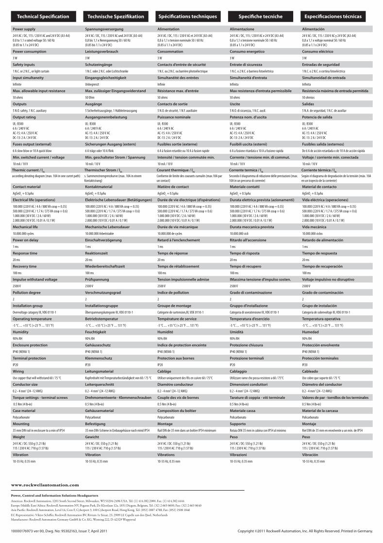
Technical Specifi cation Technische Spezifi kation Spécifi cations techniques Specifi che tecniche Especifi caciones técnicas
Power supply Spannungsversorgung Alimentation Alimentazione Alimentación
24 V AC / DC, 115 / 230 V AC and 24 V DC (A3-A4)
0.8 to 1.1 x rated voltage 50 / 60 Hz
(0.85 to 1.1 x 24 V DC)
24 V AC / DC, 115 / 230 V AC und 24 V DC (A3-A4)
0,8 bis 1,1 x Nennspannung 50 / 60 Hz
(0.85 bis 1.1 x 24 V DC)
24 V AC / DC, 115 / 230 V AC et 24 V DC (A3-A4)
0,8 à 1,1 x tension nominale 50 / 60 Hz
(0.85 á 1.1 x 24 V DC)
24 V AC / DC, 115 / 230 V AC e 24 V DC (A3-A4)
0,8 a 1,1 x tensione nominale 50 / 60 Hz
(0.85 a 1.1 x 24 V DC)
24 V AC / DC, 115 / 230 V AC y 24 V DC (A3-A4)
0,8 a 1,1 x voltaje nominal 50 / 60 Hz
(0.85 a 1.1 x 24 V DC)
Power consumption Leistungsverbrauch Consommation Consumo energetico Consumo eléctrico
3 W 3 W 3 W 3 W 3 W
Safety inputs Schutzeingänge Contacts d’entrée de sécurité Entrate di sicurezza Entradas de seguridad
1 N.C. or 2 N.C., or light curtain 1 N.C. oder 2 N.C. oder Lichtschranke 1 N.C. ou 2 N.C. ou barrière photoélectrique 1 N.C. o 2 N.C. o barriera fotoelettrica 1 N.C. o 2 N.C. o cortina fotoeléctrica
Input simultaneity Eingangsgleichzeitigkeit Simultanéité des entrées Simultaneità d’entrata Simultaneidad de entrada
Infi nite Unbegrenzt Infi nie Infi nita Infi nita
Max. allowable input resistance Max. zulässiger Eingangswiderstand Résistance max. d’entrée Max resistenza d’entrata permissibile Resistencia máxima de entrada permitida
50 ohms 50 Ohm 50 ohms 50 ohms 50 ohmios
Outputs Ausgänge Contacts de sortie Uscite Salidas
5 N.O. safety, 1 N.C. auxiliary 5 Sicherheitsausgänge, 1 Halbleiterausgang 5 N.O. de sécurité, 1 N.F. auxiliaire 5 N.O. di sicurezza, 1 N.C. ausil. 5 N.A. de seguridad, 1 N.C. de auxiliar
Output rating Ausgangsnennbelastung Puissance nominale Potenza nom. d’uscita Potencia de salida
UL: B300
6 A / 240 V AC
AC-15: 4 A / 250 V AC
DC-13: 2 A / 24 V DC
UL: B300
6 A / 240 V AC
AC-15: 4 A / 250 V AC
DC-13: 2 A / 24 V DC
UL: B300
6 A / 240 V AC
AC-15: 4 A / 250 V AC
DC-13: 2 A / 24 V DC
UL: B300
6 A / 240 V AC
AC-15: 4 A / 250 V AC
DC-13: 2 A / 24 V DC
UL: B300
6 A / 240 V AC
AC-15: 4 A / 250 V AC
DC-13: 2 A / 24 V DC
Fuses output (external) Sicherungen Ausgang (extern) Fusibles sortie (externe) Fusibili uscita (esterni) Fusibles salida (externos)
6 A slow blow or 10 A quick blow 6 A träge oder 10 A fl ink 6 A à fusion retardée ou 10 A à fusion rapide 6 A a fusione ritardata o 10 A a fusione rapida De 6 A de acción retardada o de 10 A de acción rápida
Min. switched current / voltage Min. geschalteter Strom / Spannung Intensité / tension commutée min. Corrente / tensione min. di commut. Voltaje / corriente mín. conectada
10 mA / 10 V 10 mA / 10 V 10 mA / 10 V 10 mA / 10 V 10 mA / 10 V
Thermic current / lth
Thermischer Strom / lth
Courant thermique / lth
Corrente termica / lth
Corriente térmica / lth
according derating diagram (max. 10A in one curret path) s. Summenstromgrenzkurve (max. 10A in einem
Kontaktstrang)
Conforme de limite des courants cumulés (max.10A par
un contact)
Secondo il diagramma di riduzione delle prestazioni (max.
10A in un percorso di corrente)
Según el diagrama de degradación de la tensión (máx. 10A
en un trayecto de la corriente)
Contact material Kontaktmaterial Matière de contact Materiale contatti Material de contacto
AgSnO2 + 0.5μAu AgSnO
2 + 0.5μAu AgSnO
2 + 0.5μAu AgSnO
2 + 0.5μAu AgSnO
2 + 0.5μAu
Electrical life (operations) Elektrische Lebensdauer (Betätigungen) Durée de vie électrique (d’opérations) Durata elettrica prevista (azionamenti) Vida eléctrica (operaciones)
100.000 (220 V AC / 4 A / 880 VA cosφ = 0.35)
500.000 (220 V AC / 1.7 A / 375 VA cosφ = 0.6)
1.000.000 (30 V DC / 2 A / 60 W)
2.000.000 (10 V DC / 0.01 A / 0.1 W)
100.000 (220 V AC / 4 A / 880 VA cosφ = 0.35)
500.000 (220 V AC / 1.7 A / 375 VA cosφ = 0.6)
1.000.000 (30 V DC / 2 A / 60 W)
2.000.000 (10 V DC / 0.01 A / 0.1 W)
100.000 (220 V AC / 4 A / 880 VA cosφ = 0.35)
500.000 (220 V AC / 1.7 A / 375 VA cosφ = 0.6)
1.000.000 (30 V DC / 2 A / 60 W)
2.000.000 (10 V DC / 0.01 A / 0.1 W)
100.000 (220 V AC / 4 A / 880 VA cosφ = 0.35)
500.000 (220 V AC / 1.7 A / 375 VA cosφ = 0.6)
1.000.000 (30 V DC / 2 A / 60 W)
2.000.000 (10 V DC / 0.01 A / 0.1 W)
100.000 (220 V AC / 4 A / 880 VA cosφ = 0.35)
500.000 (220 V AC / 1.7 A / 375 VA cosφ = 0.6)
1.000.000 (30 V DC / 2 A / 60 W)
2.000.000 (10 V DC / 0.01 A / 0.1 W)
Mechanical life Mechanische Lebensdauer Durée de vie mécanique Durata meccanica prevista Vida mecánica
10.000.000 cycles 10.000.000 Arbeitstakte 10.000.000 de cycles 10.000.000 cicli 10.000.000 ciclos
Power on delay Einschaltverzögerung Retard à l‘enclenchement Ritardo all‘accensione Retardo de alimentación
1 ms 1 ms 1 ms 1 ms 1 ms
Response time Reaktionszeit Temps de réponse Tempo di risposta Tiempo de respuesta
20 ms 20 ms 20 ms 20 ms 20 ms
Recovery time Wiederbereitschaftszeit Temps de rétablissement Tempo di recupero Tiempo de recuperación
100 ms 100 ms 100 ms 100 ms 100 ms
Impulse withstand voltage Prüfspannung Tension impulsionnelle admise IMassima tensione d’impulso sosten. Voltaje impulsivo no disruptivo
2500 V 2500 V 2500 V 2500 V 2500 V
Pollution degree Verschmutzungsgrad Indice de pollution Grado di contaminazione Grado de contaminación
2 2 2 2 2
Installation group Installationsgruppe Groupe de montage Gruppo d’installazione Grupo de instalación
Overvoltage catagory III, VDE 0110-1 Überspannungskategorie III, VDE 0110-1 Catègorie de surtension,III, VDE 0110-1 Categoria di sovratensione III, VDE 0110-1 Categoría de sobrevoltaje III, VDE 0110-1
Operating temperature Betriebstemperatur Température de service Temperatura d’esercizio Temperatura operativa
-5 °C .... +55 °C (+23 °F .... 131 °F) -5 °C .... +55 °C (+23 °F .... 131 °F) -5 °C .... +55 °C (+23 °F .... 131 °F) -5 °C .... +55 °C (+23 °F .... 131 °F) -5 °C .... +55 °C (+23 °F .... 131 °F)
Humidity Feuchtigkeit Humidité Umidità Humedad
90% RH 90% RH 90% RH 90% RH 90% RH
Enclosure protection Gehäuseschutz Indice de protection enceinte Protezione chiusura Protección envolvente
IP40 (NEMA 1) IP40 (NEMA 1) IP40 (NEMA 1) IP40 (NEMA 1) IP40 (NEMA 1)
Terminal protection Klemmenschutz Protection aux bornes Protezione terminali Protección terminales
IP20 IP20 IP20 IP20 IP20
Wiring Leitungsmaterial Cablâge Cablaggio Cableado
Use copper that will withstand 60 / 75 °C Kupferdraht mit Temperaturbeständigkeit von 60 / 75 °C Utiliser uniquement des fi ls en cuivre 60 / 75°C Utilizzare rame che possa resistere a 60 / 75°C Use cobre que soporte 60 / 75 °C
Conductor size Leiterquerschnitt Diamètre conducteur Dimensioni conduttori Diámetro del conductor
0.2 - 4 mm2 (24 -12 AWG) 0.2 - 4 mm2 (24 -12 AWG) 0.2 - 4 mm2 (24 -12 AWG) 0.2 - 4 mm2 (24 -12 AWG) 0.2 - 4 mm2 (24 -12 AWG)
Torque settings - terminal screws Drehmomentwerte - Klemmenschrauben Couple des vis de bornes Tarature di coppia - viti terminale Valores de par - tornillos de los terminales
0.5 Nm (4 lb•in) 0.5 Nm (4 lb•in) 0.5 Nm (4 lb•in) 0.5 Nm (4 lb•in) 0.5 Nm (4 lb•in)
Case material Gehäusematerial Composition du boîtier Materiale cassa Material de la carcasa
Polycarbonate Polycarbonat Polycarbonate Policarbonato Policarbonato
Mounting Befestigung Montage Supporto Montaje
35 mm DIN rail in enclosure to a min of IP54 35 mm DIN-Schiene in Einbaugehäuse nach mind IP54 Rail DIN de 35 mm dans un boîtier IP54 minimum Rotaia DIN 35 mm in cabina con IP54 al minimo Riel DIN de 35 mm en envolvente a un mín. de IP54
Weight Gewicht Poids Peso Peso
24 V AC / DC: 550 g (1.21 lb)
115 / 230 V AC: 710 g (1.57 lb)
24 V AC / DC: 550 g (1.21 lb)
115 / 230 V AC: 710 g (1.57 lb)
24 V AC / DC: 550 g (1.21 lb)
115 / 230 V AC: 710 g (1.57 lb)
24 V AC / DC: 550 g (1.21 lb)
115 / 230 V AC: 710 g (1.57 lb)
24 V AC / DC: 550 g (1.21 lb)
115 / 230 V AC: 710 g (1.57 lb)
Vibration Vibration Vibrations Vibrazioni Vibración
10-55 Hz, 0.35 mm 10-55 Hz, 0.35 mm 10-55 Hz, 0.35 mm 10-55 Hz, 0.35 mm 10-55 Hz, 0.35 mm
Minotaur MSR124RTMonitoring Safety Relay - Installation Instructions
Sicherheitsrelais - Installationsanleitung
Relais de sécurité de surveillance - Notice d’installation
Relé di monitoraggio di sicurezza - Istruzioni per l’installazione
Relé de seguridad de monitorización - Instrucciones de instalación
10000176973 ver 00, Dwg. No: 95302163, EO: 0329, Issue 7, April 2011
This device is intended to be part of the safety
related control system of a machine.
SAFETY NOTESBefore installation, a risk assessment
should be performed to determine
whether the specifi cations of this device
are suitable for all foreseeable
operational and environmental
characteristics of the machine to which it
is to be fi tted. At regular intervals during
the life of the machine check whether
the characteristics foreseen remain valid.
Danger of serious injuries!
Misuse can result in malfunction.
The device may only be started up, assembled
or retrofi tted by an authorized and trained personnel.
Installation must be in accordance with the
following steps.
Danger of serious injuries!
Incorrect installation or manipulation can
result in serious injuries.
Do not defeat, tamper, remove or bypass
this unit.
Responsibility cannot be accepted for
a failure of this device if the procedures
given in this sheet are not implemented
or if it is used outside the recommended
specifi cations in this sheet.
NOTE: The safety inputs of these products are
described as normally closed (N.C.), ie. with the
guard closed, actuator in place (where relevant) and
the machine able to be started.
Exposure to shock and/or vibration in excess
of those stated in IEC 60068 part: 2-6/7 should
be prevented. Adherence to the recommended
inspection and maintenance instructions forms part
of the warranty.
NOTE: All information comply with state of this
publication. Subject to change without notice.
REPAIRIf there is any malfunction or damage, no
attempts or repair should be made. The
unit should be replaced before machine
operation is allowed.
DO NOT DISMANTLE THE UNIT.
Rockwell Automation hereby declares that
MSR124RT is in conformity with Directive(s)
2004/108/EC, 2006/42/EC as specifi ed in the
Declaration of Conformity available from www.
rockwellautomation.com/ products/ certifi cation
The safety related function is the instant
interuption of the safety related contact
paths. MSR124 can be used as a safety
guard monitor or as an e-stop relay in
single or dual channel applications. The
dual channel operation shown in wiring
example 3 includes crossfault monitoring
between both e-stop circuits. That
means in case of shorts between the
two e-stop channels the MSR124 will
deenergize the outputs. This is achieved
by an electronic protection circuit in
the safety relay. After elimination of the
malfunction, the MSR124 is ready for
operation again. The application with
monitored start checks the start circuit
(Y1-Y2) and will only activate the MSR124
if there is a leading edge in this circuit.
The recovery time in this function has to
be at least 5s.
Dieses Gerät ist als Teil des sicherheitsrelevanten
Kontrollsystems einer Maschine vorgesehen.
ALLGEMEINE SICHERHEITSHINWEISEFür die Maschine, in die dieses Gerät
eingebaut wird, muss eine Risikobeurtei-
lung durchgeführt werden. Anhand der
Risikobeurteilung muss geprüft werden,
ob die Spezifi kationen dieses Gerätes
den Betriebs- und Umgebungsbedin-
gungen der Maschine entsprechen.
In regelmäßigen Abständen, während
der Lebensdauer der Maschine, ist zu
überprüfen, ob die vorhergesehenen
Spezifi kationen weiterhin gültig sind.
Gefahr von schweren Verletzungen!
Durch unsachgemäße Montage kann es zu
Fehlfunktionen kommen.
Die Montage darf nur durch fachlich qualifi zier-
tes Personal erfolgen.
Die nachfolgend beschriebenen Arbeitsschritte
müssen eingehalten werden.
Gefahr von schweren Verletzungen!
Durch unsachgemäßen Gebrauch kann es zu
schweren Verletzungen kommen.
Das Gerät niemals überbrücken.
Es kann keinerlei Verantwortung für ein
Versagen dieses Gerätes übernommen
werden, wenn die in diesem Schriftblatt
gegebenen Verfahrensweisen nicht imple-
mentiert wurden, oder wenn sie außerhalb
der auf diesem Schriftblatt empfohlenen
Spezifi kationen verwendet werden.
HINWEIS: Die Sicherheitskontakte der Schutzvor-
richtung sind als Ruhekontakte (N.C.) beschrieben,
d.h. bei geschlossener Schutzvorrichtung, sind die
Betätigungselemente in Position (falls zutreff end)
und die Maschine ist startfähig. Eine Aussetzung an
Stoßbelastungen und/oder Vibrationen, die über
den in IEC 60068, Teil 2-6/7 angegebenen Werten
liegen, sollte verhindert werden. Die Einhaltung der
empfohlenen Inspektions- und Wartungsvorschrif-
ten ist Teil der Garantie.
HINWEIS: Alle Angaben entsprechen dem
aktuellen Stand der Veröff entlichung. Änderungen
behalten wir uns jederzeit vor.
REPARATURBei Fehlfunktion oder Beschädigung
dürfen keine Reparaturversuche unter-
nommen werden. Das Gerät muss er-
setzt werden, bevor ein weiterer Betrieb
der Maschine zugelassen wird.
DAS GERÄT DARF NICHT AUSEINAN-DERGEBAUT WERDEN.
Hiermit erklärt Rockwell Automation, dass
MSR124RT wie in der Konformitätserklärung
angegeben, den Richtlinien 2004/108/EG,
2006/42/EG genügt, erhältlich von www.
rockwellautomation.com/products/certifi cation
Die sicherheitsgerichtete Funktion ist
die sofortige Unterbrechung der sicher-
heitsgerichteten Kontaktstrompfade.
Das MSR124 kann als Not-Halt-Relais und
Schutztürwächter in 1- und 2-kanaliger
Ausführung eingesetzt werden. Bei 2-ka-
naliger Ansteuerung gemäß Schaltungs-
beispiel 3, besteht Querschlusssicherheit.
Das heißt, bei einem Leitungsschluss
spricht eine elektronische Sicherung
im Gerät an und schaltet das MSR124
aus. Nach Beseitigung des Fehlers ist
das MSR124 wieder betriebsbereit. Die
Funktion des Starttasters kann bei jedem
Einschaltvorgang überprüft werden.
Dabei ist eine Mindestausschaltzeit von 5
s nicht zu unterschreiten.
Ce dispositif est étudié pour être incorporé dans le
système de contrôle pour la sécurité d’une machine.
CONSIGNES DE SÉCURITÉAvant l’installation, on doit eff ectuer une
évaluation des risques pour déterminer
si les spécifi cations de ce dispositif sont
appropriées pour toutes les caractéris-
tiques de service et du milieu d’utilisation
prévues pour la machine sur laquelle il
sera monté. Vérifi er, à des échéances ré-
gulières au cours de la vie de la machine,
que les caractéristiques prévues soient
toujours valables.
Danger de blessures graves !
Une mauvaise utilisation peut entraîner un
mauvais fonctionnement.
Seul du personnel formé et autorisé a le droit de
mettre en service, assembler ou monter l‘appareil.
L‘installation doit être eff ectuée.
Danger de blessures graves !
Une mauvaise installation ou une manipu-
lation incorrecte peut entraîner de graves
blessures.
Ne pas altérer la confi guration, modifi er, retirer
ou contourner cette unité.
Toute responsabilité est déclinée pour
les défaillances de cet appareil si les pro-
cédures décrites dans la présente notice
ne sont pas appliquées ou si l’appareil est
utilisé hors des spécifi cations recomman-
dées dans cette même notice.
REMARQUE: Les entreés de sécurité de ces
produits sont décrits comme normalement fermés
(N.F), c’est-à-dire lorsque la protection est fermée,
l’actionneur est en place (si applicable) et la machine
est en état de démarrer.
Eviter toute exposition à des chocs et/ou des
vibrations supérieurs à ceux qui sont spécifi és
dans la norme IEC 60068 part 2-6/7. Le respect des
instructions relatives à l’inspection, au contrôle et à
l’entretien de cet appareil rentre dans l’application
de la garantie.
REMARQUE : Toutes les indications fournies
correspondent aux connaissances actuelles au mo-
ment de la publication. Sous réserve de modifi cation
à tout moment.
RÉPARATIONEn cas de défaut de fonctionnement
ou d’endommagement, ne jamais
essayer de réparer le dispositif. Il doit être
remplacé avant de remettre la machine
en service.
NE JAMAIS DÉMONTER LE DISPOSITIF.
Rockwell Automation déclare par la
présente que le MSR124RT est conforme aux
directives 2004/108/EC, 2006/42/EC telles
que spécifi ées dans la déclaration de conformité
consultable et disponible sur le lien www.
rockwellautomation.com/products/certifi cation
La fonction de sécurité est assurée par
l’interruption instantanée des chemins
passant par les contacts de sécurité. Le
MSR124 peut être utilisé en tant que con-
trôleur de sécurité ou en tant que relais
d’arrêt d’urgence dans des applications
mono ou bicanal. Le fonctionnement bi-
canal illustré dans l’exemple de câblage
no3 prévoit le contrôle des défaillances
entre les deux circuits d’arrêt d’urgence.
En cas de court-circuit entre les deux
canaux d’arrêt d’urgence, le MSR124
désactive les sorties grâce à un circuit de
protection électronique prévu dans le
relais de sécurité. Après élimination de la
défaillance, le MSR124 est à nouveau prêt
à fonctionner. L’application à démarrage
contrôlé vérifie le circuit de démarrage
(Y1 -Y2) et active uniquement le MSR124
en présence d’un front d’attaque dans
le circuit.
Questo dispositivo fa parte del sistema di comando
relativo alla sicurezza di una macchina.
ISTRUZIONI DI SICUREZZAPrima dell’installazione occorre eseguire
una valutazione die rischi per stabilire se
le specifi che del dispositivo siano adatte
per tutte le caratteristiche operative ed
ambientali che si possano anticipare per
la macchina su cui deve essere montato.
Periodicamente durante la durata utile
della macchina occorre verifi care se le
caratteristiche previste rimangono valide.
Pericolo di lesioni gravi!
Un uso scorretto può causare un funzionamento
anomalo.
Il dispositivo può essere soltanto avviato, montato,
o aggiornato da personale autorizzato e addestrato.
L‘installazione deve essere conforme alle
seguenti fasi.
Pericolo di lesioni gravi!
Una installazione o un trattamento scorretti
possono causare lesioni gravi.
Non vanifi care, manomettere, rimuovere o
bypassare questa.
Ogni responsabilità è declina per un
mancato funzionamento del presente
dispositivo se le procedure indicate in
questa scheda non sono messe in atto o
se il dispositivo viene utilizzato in modo
che esula dalle specifi che consigliate in
questa scheda.
NB: Le entrate di sicurezza di questi prodotti sono de-
scritte come normalmente chiuse (NC), vale a dire con
la protezione chiusa, l’attuatore in posizione (ove sia
pertinente) e la macchina in grado di essere avviata.
Occorre evitare l’esposizione ad impatti e/o a vibrazioni
che eccedano quelli indicati nella specifi ca CEI 60068
parte: 2-6/7. L’osservanza delle istruzioni di ispezione
e di manutenzione consigliate formano parte della
garanzia.
NB: Tutte le indicazioni corrispondono allo stato
attuale della pubblicazione. Ci riserviamo il diritto di
apportare modifi che in qualsiasi momento.
RIPARAZIONEIn caso di funzionamento anomalo o di
danno, non si deve cercare di eff ettuare
una riparazione. L’unità deve essere
sostituita prima di ricominciare a far
funzionare la macchina. NON SMONTARE L’UNITÀ.
Con la presente Rockwell Automation
dichiara che MSR124RT è conforme alle
Direttive 2004/108/EC, 2006/42/EC come
specifi cate nella Dichiarazione di conformità
disponibile da www.
rockwellautomation.com/products/certifi cation
La funzione relativa alla sicurezza è
l’interruzione istantanea dei percorsi dei
contatti relativi alla sicurezza. L’MSR124
può essere utilizzato per monitorare una
protezione di sicurezza o come un relé
di arresto d’emergenza in applicazione a
canale singolo o doppio. Il funzionamen-
to a doppio canale illustrato nell’esempio
di cablaggio 3 include il controllo
incrociato di guasti tra entrambi i circuiti
di arresto d’emergenza. Ciò significa che
nel caso di cortocircuiti tra i due canali di
arresto d’emergenza l’MSR124 disattiva
le uscite. Lo si ottiene per mezzo di un
circuito elettronico di protezione nel
relé di sicurezza. Dopo aver eliminato
il funzi-onamento anomalo, l’MSR124
è nuovamente pronto a funzionare.
L’applicazione con avviamento monito-
rato controlla il circuito di avviamento
(Y1-Y2) ed attiva l’MSR124 soltanto se in
questo circuito esiste un bordo anteriore.
Este dispositivo está concebido como parte
integrante del sistema de control de seguridad
correspondiente de una máquina.
INDICACIONES DE SEGURIDADAntes de proceder a la instalación,
deberán realizarse estudios de riesgos
que determinen la idoneidad de las
especifi caciones de este dispositivo
para todas las características operativas
y ambientales previsibles de la máquina
donde va a ser colocado. Revise regu-
larmente la máquina para cerciorarse de
que las características previsibles siguen
siendo válidas.
Peligro de lesiones graves!
Un uso incorrecto puede derivar en fallos de
funcionamiento.
El dispositivo sólo podrá arrancar, montarse o adap-
tarse por personal autorizado y debidamente capacitado.
La instalación deberá realizarse según los pasos
que fi guran a continuación.
Peligro de lesiones graves!
La incorrecta instalación o manipulación de
este producto puede producir lesiones graves.
No malogre, manipule, retire ni desvíe esta
unidad unità.
Toda responsabilidad esta declina por
averíasen el dispositivo resultantes del
incumplimiento de las instrucciones
expuestas en esta hoja o del uso ajeno a
las especifi caciones aquí recomendadas.
NOTA: Los contactos de entrada de estos productos
se describen como normalmente cerrados (o N.C.),
es decir, con el protector cerrado, el accionador en
su lugar (si procede) y la máquina en condiciones
de arrancar.
Deberá evitarse la exposición a golpes o vibraciones
superiores a los niveles indicados en la CEI 60068:
2-6/7. El cumplimiento de las instrucciones de
inspección y mantenimiento recomendadas forma
parte de la garantía.
NOTA: Todos los datos se corresponden con la fecha
de publicación. Nos reservamos el derecho a introducir
cambios sin previo aviso.
REPARACIÓNSi hubiera algún defecto o avería, no
intente repararlos. Sustituya la unidad
antes de autorizar el funcionamiento de
la máquina.
NO DESMONTE LA UNIDAD.
Rockwell Automation declara por la
presente que el MSR124RT cumple las
Directivas 2004/108/EC, 2006/42/ EC según
se especifi ca en la Declaración de conformidad. Para
obtenerla, visite www.
rockwellautomation.com/products/certifi cation
La función de seguridad relacionada
es la interrupción instantánea de los
trayectos de contacto de seguridad rela-
cionados. El MSR124 puede usarse como
monitor de protector de seguridad o
como relé de parada de emergencia
en aplicaciones mono o bicanales. El
funcionamiento bicanal mostrado en el
ejemplo de cableado 3 incluye monito-
rización de fallos cruzados entre los dos
circuitos de parada de emergencia. Eso
significa que si ocurren cortocircuitos
entre los dos canales de parada de emer-
gencia, el MSR124 desactivará las salidas.
Para ello existe un circuito de protección
electrónica en el relé de seguridad. Una
vez eliminado el fallo, el MSR124 queda
listo para volver a funcionar. La aplicaci-
ón con arranque monitorizado verifica
el circuito de arranque (Y1-Y2) y sólo
activará el MSR124 si el circuito dispone
de borde de ataque.
English (original)
Declaration of Conformity Konformitätserklärung Déclaration de Conformité Dichiarazione di conformità Declaración de conformidad
Deutsch (original) Français (traduction) Italiano (traduzione) Español (traducción)
WARNING WARNUNG AVERTISSEMENT AVVERTENZA! ADVERTENCIA!
AVERTISSEMENT AVVERTENZA! ADVERTENCIA!WARNUNGWARNING
10000176973 ver 00, Dwg. No: 95302163, Issue 7, April 2011 Copyright ©2011 Rockwell Automation, Inc. All Rights Reserved. Printed in Germany.
Functional Description Funktionsbeschreibung Description fonctionnelle Descrizione funzionale Descripción funcional
Dimensions / Abmessungen / Dimensions / Dimensioni / Dimensiones
The safety relay MSR124RT can be used
in safety circuits according to DIN EN
60204-1/VDE 0113 part 1. Based on the
operation mode and wiring the below
mentioned safey requirements are
achievebale in maximum.
Specifi cations are applicable only if the
safety function is demanded at least
once within 6 months. All diagnostic
test are carried out at least before next
demand. The mission time (TM) for the
proof test interval (PTI) is adopted.
Components failure rates according to
SN29500.
Das Sicherheits-Relais MSR124RT kann
in Sicherheitsstromkreisen nach DIN
EN 60204-1/VDE 0113 Teil 1 eingesetzt
werden. Je nach äußerer Beschaltung sind
max. die unten aufgeführten Anforderun-
gen zu erreichen.
Die Anforderungen der aufgeführten
Normen werden erfüllt, wenn die
Sicherheitsfunktion mindestens einmal
innerhalb von 6 Monaten betätigt wird.
Alle Diagnosetests werden spätestens bis
zur nächsten Anforderung ausgeführt.
Als Intervall für Wiederholungsprüfungen
(PTI) wird die Nutzungsdauer (TM) ange-
nommen, Fehlerraten der Komponenten
gemäß SN29500.
Le relais de sécurité MSR124RT peut être
utilisé sur des circuits de sécurité con-
formément à la norme DIN EN 60204-1/
VDE 0113 partie 1. En fonction du mode
d‘exploitation et du câblage, les spécifi -
cations en matière de sécurité ci-dessous
peuvent êter suivies dans leur intégralité.
Les spécifi cations ne s‘appliquent que si
les actions de sécurité sont demandées au
moins fois tous les 6 mois. Tous les essais
de diagnostic sont entrepris au moins
avant la requête suivante. La période de
mission (PM), en ce qui concerne l‘interval
des essais (IE), est adoptée.
Les pannes des composants sont classées
en conformité avec la norme SN29500.
Il relè di sicurezza MSR124RT può essere
usato in circuiti di sicurezza secondo DIN
EN 60204-1/VDE 0113 parte 1. Sulla base
del modo di funzionamento e il cablaggio
i requisiti di sicurezza sotto indicati sono
realizzabili in condizioni di massimo.
Le specifi che sono valide soltanto se la
funzione di sicurezza viene richiesta al-
meno una volta ogni 6 mesi. Tutti i test di
diagnostica sono eseguiti almeno prima
della richiesta successiva. È adottato il
tempo di missione (TM) per l‘intervallo del
test di prova (PTI).
Frequenza guasti componenti secondo
SN29500.
El relé de seguridad MSR124RT puede
usarse en circuitos de seguridad según la
norma DIN EN 60204-1/VDE 0113 parte 1.
En función del modo de funcionamiento
y cableado, los requisitos de seguridad
que se citan más abajo son factibles en
grado máximo.
Las especifi caciones son aplicables
únicamente si se precisa la función de
seguridad al menos una vez cada 6
meses. Todas las pruebas diagnósticas se
realizarán como muy tarde antes de la si-
guiente petición. Se adopta el tiempo de
misión (TM) del intervalo de prueba (PTI).
Índices de fallo de los componentes
según SN29500.
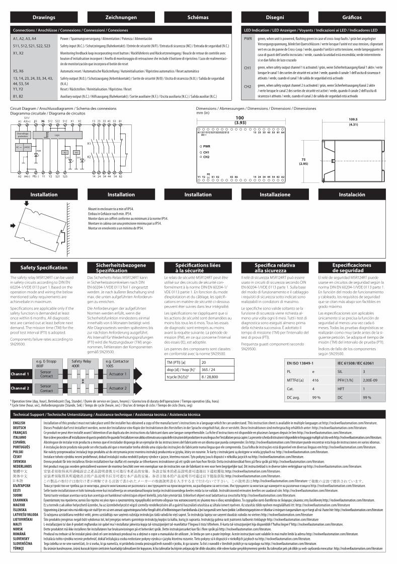
Drawings Zeichnungen Schémas Disegni Gráfi cos
Circuit Diagram / Anschlussdiagramm / Schema des connexions Diagramma circuitale / Diagrama de circuitos
Connections / Anschlüsse / Connexions / Connessioni / Conexiones
A1, A2, A3, A4
S11, S12, S21, S22, S23
X1, X2
X5, X6
13, 14, 23, 24, 33, 34, 43, 44, 53, 54Y1, Y2
81, 82
Power / Spannungsversorgung / Alimentation / Potenza / Alimentación
Safety input (N.C.) / Schutzeingang (Ruhekontakt) / Entrée de sécurité (N/F) / Entrata di sicurezza (NC) / Entrada de seguridad (N.C.)
Monitoring feedback loop incorporating reset button / Rückführkreis und Rücksetzeneingang / Boucle de retour de contrôle avec
bouton d‘initialisation incorporé / Anello di monitoraggio di retroazione che include il bottone di ripristino / Lazo de realimentaci-
ón de monitorización que incorpora el botón de reset
Automatic reset / Automatische Rückstellung / Autoinitialisation / Ripristino automatico / Reset automático
Safety output (N.O.) / Schutzausgang (Arbeitskontakt) / Sortie de sécurité (N/O) / Uscita di sicurezza (N.O.) / Salida de seguridad
(N.A.)
Reset / Rückstellen / Reinitialisation / Ripristino / Reset
Auxiliary output (N.C.) / Hilfsausgang (Ruhekontakt) / Sortie auxiliaire (N.F.) / Uscita ausiliaria (N.C.) / Salida auxiliar (N.C.)
Technical Support / Technische Unterstützung / Assistance technique / Assistenza tecnica / Asistencia técnica
ENGLISH
DEUTSCH
FRANÇAIS
ITALIANO
ESPAÑOL
PORTUGUÊS
POLSKI
ČESKY
SVENSKA
NEDERLANDS
БЪЛГАРСКИ
EESTI
SUOMI
ΕΛΛΗΝΙΚΆ
MAGYAR
ÍSLENSKA
LATVIEŠU VALODA
LIETUVIRŠKAI
MALTI
NORSK
ROMÂNĂ
SLOVENSKY
SLOVENŠČINA
TÜRKÇE
Installation of this product must not take place until the installer has obtained a copy of the manufacturer’s instructions in a language which he can understand. This instruction sheet is available in multiple languages at http://rockwellautomation.com/literature.
Dieses Produkt darf erst installiert werden, wenn der Installateur eine Kopie der Instruktionen des Herstellers in der Sprache eingeholt hat, die er versteht. Diese Instruktionen sind mehrsprachig erhältlich unter: http://rockwellautomation.com/literature.
Ce produit ne peut être installé avant l’obtention d’un duplicata des instructions du fabricant dans une langue compréhensible. La fi che d’instructions est disponible en plusieurs langues depuis le lien http://rockwellautomation.com/literature.
Non si deve procedere all’installazione di questo prodotto fin quando l’installatore non abbia ottenuto una copia delle istruzioni del produttore in una lingua che l’installatore possa capire. La presente scheda di istruzioni è disponibile in linguaggi multipli sul sito web http://rockwellautomation.com/literature.
Absténgase de instalar este producto a menos que el instalador disponga de un ejemplar de las instrucciones del fabricante en un idioma que pueda comprender. En http://rockwellautomation.com/literature puede encontrar esta hoja de instrucciones en varios idiomas.
A instalação deste produto não pode ser efectuada até que o montador tenha obtido uma cópia das instruções do fabricante numa língua que ele compreenda. Essa folha de instruções está disponível em diversas línguas em http://rockwellautomation.com/literature.
Nie należy przeprowadzać instalacji tego produktu aż do otrzymania przez montera instrukcji producenta w języku, który on rozumie. Te karty z instrukcjami są dostępne w wielu językach na: http://rockwellautomation.com/literature.
Instalace tohoto výrobku nesmí proběhnout, dokud instalující osoba neobdrží pokyny výrobce v jazyce, kterému rozumí. Tyto pokyny jsou k dispozici v několika jazycích na http://rockwellautomation.com/literature.
Denna produkt får inte installeras förrän installatören har skaff at ett exemplar av tillverkarens instruktioner på ett språk som han/hon förstår. Detta instruktionsblad fi nns på fl era språk på http://rockwellautomation.com/literature.
Het product mag pas worden geïnstalleerd wanneer de monteur beschikt over een exemplaar van de instructies van de fabrikant in een voor hem begrijpelijke taal. Dit instructieblad is in diverse talen verkrijgbaar op http://rockwellautomation.com/literature.
: http://rockwellautomation.com/literature
: http://rockwellautomation.com/literature
http://rockwellautomation.com/literature
Това устройство не трябва да се монтира, докато монтажника не разполага с инструкциите на производителя, на разбираем за него език. Инструкциите за монтаж ще намерите на различни езици в http://rockwellautomation.com/literature.
Selle toote installatsioon ei tohi toimuda enne kui installeerija on omandanud koopia tootja instruktsioonidega keeles mida ta ise valdab. Instruktsioonid erinvates keeltes on saadaval siin: http://rockwellautomation.com/literature.
Tämä tuote voidaan asentaa vasta kun asentaja on hankkinut valmistajan ohjeet kielellä, jota hän ymmärtää. Erikieliset ohjeet ovat ladattavissa sivustolta http://rockwellautomation.com/literature.
Εγκατάσταση του προϊόντος αυτού δεν πρέπει να γίνει πριν ο εγκαταστάτης προμηθευθεί αντίτυπο οδηγιών του κατασκευαστή σε γλώσσα που ο ίδιος καταλαβαίνει. Το εγχειρίδιο αυτό διατίθεται σε διόφορες γλώσσες στη διεύθυνση http://rockwellautomation.com/literature.
Ez a termék csak akkor helyezhető üzembe, ha az üzembehelyezést végző személy rendelkezésére áll a gyártó használati utasítása az általa ismert nyelven. Az utasítás több nyelven megtalálható itt: http://rockwellautomation.com/literature
Uppsetning á þessari vöru má ekki eiga sér stað fyrr en sá sem annast uppsetninguna hefur fengið afrit af leiðbeiningum framleiðanda á því tungumáli sem hann þekkir. Leiðbeiningarpésinn er tiltækur á mörgum tungumálum og er hægt að ná í hann hér: http://rockwellautomation.com/literature
Šī ražojuma uzstādīšanu nedrīkst veikt, pirms uzstādītājs nav saņēmis ražotāja instrukcijas tādā valodā ko viņš saprot. Šo instrukciju lapiņu var saņemt daudzās valodās no vietnes http://rockwellautomation.com/literature
Šito produkto įrengimas negali būti vykdomas tol, kol įrengėjas neturės gamintojo instrukcijų kopijos ta kalba, kurią jis supranta. Instrukciją galima rasti įvairiomis kalbomis tinklapyje http://rockwellautomation.com/literature
L-installazzjoni ta’ dan il-prodott mgħandux isir qabel ma l-installatur jakwista kopja tal-istruzzjonijiet tal-manifattur f ’lingwa li tista’ tiftiehem. Il-karta tal-istruzzjonijiet hija disponibbli f ’ħafna lingwi f ’http://rockwellautomation.com/literature.
Dette produktet må ikke installeres før installatøren har bruksanvisningen på et behersket språk. Dette instruksjonsarket kan fås i fl ere språk på http://rockwellautomation.com/literature.
Produsul nu trebuie să fi e instalat până când cel care instalează produsul nu a obţinut o copie a manualului de utilizare , în limba pe care o poate înţelege. Aceste instrucţiuni sunt valabile în mai multe limbi la adresa http://rockwellautomation.com/literature.
Inštalácia tohto výrobku nesmie prebehnúť, dokiaľ inštalujúca osoba nedostane pokyny výrobca v jazyku ktorému rozumie. Tieto pokyny sú k dispozícii v niekoľkých jazykoch na http://rockwellautomation.com/literature.
Tega izdelka se ne sme nameščati, če si oseba, ki ga namešča, ni priskrbela izvoda proizvajalčevih navodil v jeziku, ki ga razume. Ta list z navodili v številnih jezikih je na razpolago na http://rockwellautomation.com/literature.
Bu ürünün kurulmasının, ürünü kuracak kişinin üreticinin hazırladığı talimatların bir kopyasını, ki bu talimatlar bu kişinin anlayacağı bir dilde olacaktır, elde edene kadar gerçekleşmemesi gerekir. Bu talimatlar pek çok dilde şu web-sayfasında mevcuttur: http://rockwellautomation.com/literature
mm (in)
LED Indication / LED Anzeigen / Voyants / Indicazioni ai LED / Indicadores LED
PWR
CH1
CH2
green, when unit is powered, fl ashing green in case of cross-loop faults / grün bei angelegter
Versorgungsspannung, blinkt bei Querschlüssen / verte lorsque l‘unité est sous tension, clignotant
vert en cas de panne de Cross-Loop / verde, quando l‘unità è sotto tensione, verde lampeggiante in
caso di guasti dell‘anello incrociato / verde, cuando la unidad está encendida; verde intermitente
si se dan fallos de lazo cruzado
green, when safety output channel 1 is activated / grün, wenn Sicherheitsausgang Kanal 1 aktiv / verte
lorsque le canal 1 des sorties de sécurité est activé / verde, quando il canale 1 dell‘uscita di sicurezza è
attivato / verde, cuando el canal 1 de salida de seguridad está activado
green, when safety output channel 2 is activated / grün, wenn Sicherheitsausgang Kanal 2 aktiv
/ verte lorsque le canal 2 des sorties de sécurité est activé / verde, quando il canale 2 dell‘uscita di
sicurezza è attivato / verde, cuando el canal 2 de salida de seguridad está activado
1 Operation time (day, hour), Betriebszeit (Tag, Stunde) / Durée de service en (jours, heures) / Giorno/ora di durata dell’operazione / Tiempo operativo (día, hora)2 Cycle time (hour, sec), Anforderungsrate (Stunde, Sek) / Temps de cycle (heure, sec) / Ora/sec di tempo di ciclo / Tiempo de ciclo (hora, seg)
EN ISO 13849-1 IEC 61508/IEC 62061
PL e SIL 3
MTTFd [a] 416 PFH [1/h] 2,00E-09
Cat. 4 HFT 1
DC avg. 99 % DC 99 %
Safety Specifi cationSicherheitsbezogeneSpezifi kation
Spécifi cations liées à la sécurité
Specifi ca relativa alla sicurezza
Especifi caciones de seguridad
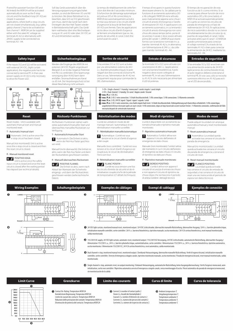
Wiring Examples Schaltungsbeispiele Exemples de câblages Esempi di cablaggi Ejemplos de conexión
Limit Curve Grenzkurve Limite des courants Curva di limite Curva de tolerancia
24 V DC light curtain, monitored manual reset, monitored output / 24 V DC Lichtschranke, überwachte manuelle Rückstellung, überwachter Ausgang / 24 V c.c. barrière photoélectrique,
initialisation manuelle contrôlée, sortie contrôlée / 24 V c.c. barriera fotoelettrica, ripristino manuale, uscita monitorata / 24 V CA cortina fotoeléctrica, reset manual monitorizado,
salida monitorizada
115/230 V AC supply, 24 V DC light curtain, automatic reset, monitored output / 115/230 V AC Versorgung, 24 V DC Lichtschranke, automatische Rückstellung, überwachter Ausgang /
Alimentation 115/230 V c.a., 24 V c.c. barrière photoélectrique, autoinitialisation, sortie contrôlée / Alimentazione 115/230 V c.a., 24 V c.c. barriera fotoelettrica, ripristino automatico,
uscita monitorata / Alimentación 115/230 V CC, 24 V CA cortina fotoelettrica, reset automático, salida monitorizada
Dual channel e-stop, monitored manual reset, monitored output / Zweikanal-Notauseingang, überwachte manuelle Rückstellung / Arrêt d‘urgence bicanal, initialisation manuelle
contrôlée, sortie contrôlée / Arresto d‘emergenza a doppio canale, ripristino monitorato manuale, uscita monitorata / Parada de emergencia bicanal, reset manual monitorizado, salida
monitorizada
Single channel e-stop, automatic reset, no output monitoring / Einkanal-Notauseingang, automatische Rückstellung, keine Ausgangsüberwachung / Arrêt d‘urgence monocanal, auto-
initialisation, sortie non contrôlée / Ripristino automatico arresto d‘emergenza a singolo canale, senza monitoraggio d‘uscita / Reset automático de parada de emergencia monocanal,
sin monitorización de la salida
If wired for autostart function (X5 and
X6 linked) the MSR124 will be activated
automatically as soon as the E-stop
circuits and the feedback loop (X1-X2) are
closed. In autostart
applications, where both e-stop circuits
are not closed simultaneously, (e.g. safety
gates) channel 2 has to be activated be-
fore channel 1. MSR124 can be supplied
either with the rated AC voltage via
terminals A1-A2 or alternatively with
24VDC supply to be connected via
terminals A3 - A4.
If the inputs S12 and S22 will be activated
with external 24 V DC, (light curtain
application), the negative pole has to be
connected to terminal PE. In that case
power supply on A1-A2 is only necessary
to drive the Power-LED.
Reset modes - Unit is available with
automatic/manual start and manual
monitored reset.
T - Automatic/manual start
Automatic: Unit is active once the
e-stop circuit has been closed.
Manual (not monitored): Unit is active
once the e-stop circuit is closed and then
the reset circuit is closed.
R - Manual monitored reset
POSITIVE EDGE:Unit is active once the safety
input circuit is closed and once the reset
circuit is closed after the waiting period
has elapsed (see technical details).
Soll das Gerät automatisch über die
Versorgungsspannung eingeschaltet
werden, so sind die Klemmen X5 und X6
zu brücken. Bei dieser Betriebsart ist zu
beachten, dass S23 vor S12 geschlossen
sein muss, damit das Gerät nach dem
Entriegeln des Not-Halt-Tasters wieder
in Betriebsbereitschaft geht. Das Gerät
kann wahlweise über eine Wechselspan-
nung an A1 und A2 oder über 24 V DC an
A3 und A4 betrieben werden.
Werden die Eingänge des MSR124 mit
externen 24 V DC Pegeln angesteuert
(Beispiel 2), so ist das negative Potential
mit PE(-) zu verbinden. Eine Spannungs-
versorgung über A1/A2 kann dann
entfallen. Stromaufnahme pro Kanal
ca. 65 mA. Der Verpolungsschutz ist bei
dieser Beschaltung nicht wirksam.
Als Rücksetz-Funktionen stehen wahl-
weise automatisch/manueller Start und
überwachtes manuelles Rücksetzen zur
Verfügung.
T - Automatisch/manueller Start
Automatisch: Die Einheit ist aktiv,
wenn der Not-Aus-Taster geschlos-
sen wird.
Manuell (nicht überwacht): Die Einheit ist
aktiv, wenn der Not-Aus-Taster und dann
der Rücksetzkreis geschlossen werden.
R - Manuell überwachtes Rücksetzen
POSITIVE FLANKE: Die Einheit ist aktiv, wenn nach
Ablauf der Wartezeit der Sicherheits-
eingangs- und dann der Rücksetzkreis
geschlossen werden (siehe technische
Daten).
Le temps de rétablissement de cette fon-
ction doit être de 5 secondes minimum.
Si la fonction de démarrage automatique
est prévue (X5 et X6 connectées), le
MSR124 est automatiquement activé à
la mise sous tension si les circuits d’arrêt
d’urgence et la boucle de feed-back
(X1-X2) sont fermés. Dans les applications
où les deux circuits d’arrêt d’urgence
se ferment simultanément (par ex. les
portes de sécurité), le canal 2 doit être
activé avant le canal 1.
Si les entrées S12 et S22 sont activées
par une alimentation externe de 24 V
c.c. (barrière photoélectrique), le pole
négatif doit être connecté à la borne PE.
Dans ce cas, l’alimentation de A1-A2 est
uniquement requise pour commander la
DEL d’alimentation.
L‘unité est utilisée en mode de dé-
marrage manuel / automatique et en
réinitialisation manuelle surveillée.
T - Réinitialisation manuelle/automatique
Automatique : L’unité est sous
tension et le circuit d’arrêt d’urgence
a été coupé.
Manuelle (non contrôlée) : l’unité est sous
tension et le circuit d’arrêt d’urgence est
coupé puis, le circuit de réinitialisation
l’est à son tour.
R - Réinitialisation manuelle surveillée
FLANC POSITIF :L’unité est sous tension une fois
les circuits d’entrée de sécurité et de ré-
initialisation coupés à la fin de la période
de temporisation (cf. détails techniques).
Il tempo di recupero in questa funzione
deve essere almeno 5s. Se cablato per la
funzione di avviamento automatico (X5
e X6 collegati) l’MSR124 viene attivato
auto-maticamente appena sono chiusi i
circuiti di arresto d’emergenza e l’anello
di retroazione (X1-X2). In applicazioni con
avviamento automatico, in cui entrambi i
circuiti di arresto d’emergenza non sono
chiusi allo stesso tempo (ad es. porte di
sicurezza), il canale 2 deve essere attivato
prima del canale 1. L’MSR124 può essere
fornito con la tensione nominale in c.a.
tramite i terminali A1-A2 o, in alternativa,
con l’alimentazione di 24V c.c. da colle-
gare tramite i terminali A3 - A4.
Se le entrate S12 e S22 sono attivate con
una tensione di 24V c.c. (applicazione
con una barriera fotoelettrica), il polo
negativo deve essere collegato al
terminale PE. In tal caso l’alimentazione
su A1-A2 è solo necessaria per alimentare
il LED di potenza.
L‘unità è disponibile con avviamento au-
tomatico/manuale e ripristino manuale
monitorato.
T - Ripristino automatico/manuale
Automatico: l’unità è attiva non
appena il circuito dell’arresto di
emergenza sia stato chiuso.
Manuale (non monitorato): l’unità è attiva
dal momento in cui il circuito dell’arresto
di emergenza sia stato chiuso e il circuito
di ripristino sia stato poi chiuso.
R - Ripristino manuale monitorato
BORDO POSITIVO:L’unità è attiva non appena il
circuito di sicurezza di entrata sia chiuso
e non appena il circuito di ripristino sia
chiuso dopo che sia trascorso il periodo
di attesa (vedere i dettagli tecnici).
El tiempo de recuperación de esta
función es de 5 s como mínimo. Si se
conecta para ofrecer función de inicio
automático (X5 y X6 conectados), el
MSR124 se activará automáticamente
en cuanto se cierren los circuitos de
parada de emergencia y el lazo de
realimentación (X1-X2). En aplicaciones
de inicio automático donde no se cierren
simultáneamente los dos circuitos (p. ej.
puertas de seguridad), el canal 2 debe
activarse antes que el canal 1. El MSR124
puede suministrarse para conectar
el voltaje nominal CA a través de los
terminales A1-A2 o bien para conectar
la alimentación de 24 VCC mediante los
terminales A3 - A4.
Si las entradas S12 y S22 se activan con
una alimentación externa de 24 VCD
(aplicaciones de cortina fotoeléctrica),
el polo negativo deberá conectarse al
terminal PE. En ese caso, sólo se necesita
suministro eléctrico en A1-A2 para acti-
var el LED de encendido.
Puede adquirir la unidad con arranque
automático/manual y reset monitorizado
manual.
T - Reset automático/manual
Automático: La unidad queda
activada tras cerrarse el circuito de
parada de emergencia.
Manual (no monitorizado): La unidad
queda activada tras cerrarse el circuito
de parada de emergencia y cerrarse el
circuito de reset.
R - Reset manual monitorizado
FLANCO POSITIVO: La unidad queda activada
tras cerrarse el circuito de entrada de
seguridad y tras cerrarse el circuito de
reset una vez transcurrido el periodo de
espera (ver datos técnicos).
TM (PTI) [a] 20
dop [d] / hop [h]1 365 / 24
tcycle [h]/[s]2 8 / 28,800
Installation Installation Installation Installazione Instalación
Mount in enclosure to a min of IP54.
Einbau in Gehäuse nach min. IP54.
Monter dans un coff ret conforme au minimum à la norme IP54.
Montare in cabina con una protezione minima pari a IP54.
Montar en envolvente a un mínimo de IP54.
Contact De-Rating: Temperature MSR124
Kontaktstrom Begrenzung: Temperatur MSR124
Limite de courant des contacts: Température MSR124
Riduzione delle prestazioni dei contatti: Temperatura MSR124
Disminución de potencia del contacto: Temperatura MSR124
Current 2 x number of contact paths 2
Strom 2 x, Anzahl der Kontaktpfade 2
Courant 2 x, nombre d’éléments de contacts 2
Corrente 2 x, numero dei percorsi dei contatti 2
Corriente 2 x, número de trayectos de contacto 2
Ambient temperature °CUmgebungstemperatur °CTempérature ambiante °CTemperatura ambiente °CTemperatura ambiente °C
Safety Input Sicherheitseingänge Sorties de sécurité Entrate di sicurezza Entradas de seguridad
Reset Rücksetz-Funktionen Réinitialisation des modes Modi di ripristino Modos de reset
1-CH = Single-channel / 1-kanalig / monocanal / canale singolo / canal simple
2-CH = Dual-channel / 2-kanalig / bi-canal / doppio canale / bicanal
max. PL c: 1-CH; N.C.
max. PL d: 2-CH; 3-wire connection / 3-Draht Anschlusstechnik / 3-fi ls cennectique / 3-fi li connessione / 3-fi lamento connexión
max. PL e: 2-CH; 24V DC signal / Signal / signal / segnale / señal
max. PL e: 2-CH; 4-wire connection, cross faults require fault reset / 4-Draht Anschlusstechnik, Fehlerquittierung nach Querschluss erforderlich / 4-fi ls connectique,
acquittement d’erreur nécessaire après un court-circuit / 4-fi li connessione, dopo un loop trasversale occorre tacitare l‘errore / 4-fi lamento connexión, confi rmación del fallo
necesaria después de cortocircuito transversal
Dimensions / Abmessungen / Dimensions / Dimensioni / Dimensiones
The safety relay MSR124RT can be used
in safety circuits according to DIN EN
60204-1/VDE 0113 part 1. Based on the
operation mode and wiring the below
mentioned safey requirements are
achievebale in maximum.
Specifi cations are applicable only if the
safety function is demanded at least
once within 6 months. All diagnostic
test are carried out at least before next
demand. The mission time (TM) for the
proof test interval (PTI) is adopted.
Components failure rates according to
SN29500.
Das Sicherheits-Relais MSR124RT kann
in Sicherheitsstromkreisen nach DIN
EN 60204-1/VDE 0113 Teil 1 eingesetzt
werden. Je nach äußerer Beschaltung sind
max. die unten aufgeführten Anforderun-
gen zu erreichen.
Die Anforderungen der aufgeführten
Normen werden erfüllt, wenn die
Sicherheitsfunktion mindestens einmal
innerhalb von 6 Monaten betätigt wird.
Alle Diagnosetests werden spätestens bis
zur nächsten Anforderung ausgeführt.
Als Intervall für Wiederholungsprüfungen
(PTI) wird die Nutzungsdauer (TM) ange-
nommen, Fehlerraten der Komponenten
gemäß SN29500.
Le relais de sécurité MSR124RT peut être
utilisé sur des circuits de sécurité con-
formément à la norme DIN EN 60204-1/
VDE 0113 partie 1. En fonction du mode
d‘exploitation et du câblage, les spécifi -
cations en matière de sécurité ci-dessous
peuvent êter suivies dans leur intégralité.
Les spécifi cations ne s‘appliquent que si
les actions de sécurité sont demandées au
moins fois tous les 6 mois. Tous les essais
de diagnostic sont entrepris au moins
avant la requête suivante. La période de
mission (PM), en ce qui concerne l‘interval
des essais (IE), est adoptée.
Les pannes des composants sont classées
en conformité avec la norme SN29500.
Il relè di sicurezza MSR124RT può essere
usato in circuiti di sicurezza secondo DIN
EN 60204-1/VDE 0113 parte 1. Sulla base
del modo di funzionamento e il cablaggio
i requisiti di sicurezza sotto indicati sono
realizzabili in condizioni di massimo.
Le specifi che sono valide soltanto se la
funzione di sicurezza viene richiesta al-
meno una volta ogni 6 mesi. Tutti i test di
diagnostica sono eseguiti almeno prima
della richiesta successiva. È adottato il
tempo di missione (TM) per l‘intervallo del
test di prova (PTI).
Frequenza guasti componenti secondo
SN29500.
El relé de seguridad MSR124RT puede
usarse en circuitos de seguridad según la
norma DIN EN 60204-1/VDE 0113 parte 1.
En función del modo de funcionamiento
y cableado, los requisitos de seguridad
que se citan más abajo son factibles en
grado máximo.
Las especifi caciones son aplicables
únicamente si se precisa la función de
seguridad al menos una vez cada 6
meses. Todas las pruebas diagnósticas se
realizarán como muy tarde antes de la si-
guiente petición. Se adopta el tiempo de
misión (TM) del intervalo de prueba (PTI).
Índices de fallo de los componentes
según SN29500.
Drawings Zeichnungen Schémas Disegni Gráfi cos
Circuit Diagram / Anschlussdiagramm / Schema des connexions Diagramma circuitale / Diagrama de circuitos
Connections / Anschlüsse / Connexions / Connessioni / Conexiones
A1, A2, A3, A4
S11, S12, S21, S22, S23
X1, X2
X5, X6
13, 14, 23, 24, 33, 34, 43, 44, 53, 54Y1, Y2
81, 82
Power / Spannungsversorgung / Alimentation / Potenza / Alimentación
Safety input (N.C.) / Schutzeingang (Ruhekontakt) / Entrée de sécurité (N/F) / Entrata di sicurezza (NC) / Entrada de seguridad (N.C.)
Monitoring feedback loop incorporating reset button / Rückführkreis und Rücksetzeneingang / Boucle de retour de contrôle avec
bouton d‘initialisation incorporé / Anello di monitoraggio di retroazione che include il bottone di ripristino / Lazo de realimentaci-
ón de monitorización que incorpora el botón de reset
Automatic reset / Automatische Rückstellung / Autoinitialisation / Ripristino automatico / Reset automático
Safety output (N.O.) / Schutzausgang (Arbeitskontakt) / Sortie de sécurité (N/O) / Uscita di sicurezza (N.O.) / Salida de seguridad
(N.A.)
Reset / Rückstellen / Reinitialisation / Ripristino / Reset
Auxiliary output (N.C.) / Hilfsausgang (Ruhekontakt) / Sortie auxiliaire (N.F.) / Uscita ausiliaria (N.C.) / Salida auxiliar (N.C.)
Technical Support / Technische Unterstützung / Assistance technique / Assistenza tecnica / Asistencia técnica
ENGLISH
DEUTSCH
FRANÇAIS
ITALIANO
ESPAÑOL
PORTUGUÊS
POLSKI
ČESKY
SVENSKA
NEDERLANDS
БЪЛГАРСКИ
EESTI
SUOMI
ΕΛΛΗΝΙΚΆ
MAGYAR
ÍSLENSKA
LATVIEŠU VALODA
LIETUVIRŠKAI
MALTI
NORSK
ROMÂNĂ
SLOVENSKY
SLOVENŠČINA
TÜRKÇE
Installation of this product must not take place until the installer has obtained a copy of the manufacturer’s instructions in a language which he can understand. This instruction sheet is available in multiple languages at http://rockwellautomation.com/literature.
Dieses Produkt darf erst installiert werden, wenn der Installateur eine Kopie der Instruktionen des Herstellers in der Sprache eingeholt hat, die er versteht. Diese Instruktionen sind mehrsprachig erhältlich unter: http://rockwellautomation.com/literature.
Ce produit ne peut être installé avant l’obtention d’un duplicata des instructions du fabricant dans une langue compréhensible. La fi che d’instructions est disponible en plusieurs langues depuis le lien http://rockwellautomation.com/literature.
Non si deve procedere all’installazione di questo prodotto fin quando l’installatore non abbia ottenuto una copia delle istruzioni del produttore in una lingua che l’installatore possa capire. La presente scheda di istruzioni è disponibile in linguaggi multipli sul sito web http://rockwellautomation.com/literature.
Absténgase de instalar este producto a menos que el instalador disponga de un ejemplar de las instrucciones del fabricante en un idioma que pueda comprender. En http://rockwellautomation.com/literature puede encontrar esta hoja de instrucciones en varios idiomas.
A instalação deste produto não pode ser efectuada até que o montador tenha obtido uma cópia das instruções do fabricante numa língua que ele compreenda. Essa folha de instruções está disponível em diversas línguas em http://rockwellautomation.com/literature.
Nie należy przeprowadzać instalacji tego produktu aż do otrzymania przez montera instrukcji producenta w języku, który on rozumie. Te karty z instrukcjami są dostępne w wielu językach na: http://rockwellautomation.com/literature.
Instalace tohoto výrobku nesmí proběhnout, dokud instalující osoba neobdrží pokyny výrobce v jazyce, kterému rozumí. Tyto pokyny jsou k dispozici v několika jazycích na http://rockwellautomation.com/literature.
Denna produkt får inte installeras förrän installatören har skaff at ett exemplar av tillverkarens instruktioner på ett språk som han/hon förstår. Detta instruktionsblad fi nns på fl era språk på http://rockwellautomation.com/literature.
Het product mag pas worden geïnstalleerd wanneer de monteur beschikt over een exemplaar van de instructies van de fabrikant in een voor hem begrijpelijke taal. Dit instructieblad is in diverse talen verkrijgbaar op http://rockwellautomation.com/literature.
: http://rockwellautomation.com/literature
: http://rockwellautomation.com/literature
http://rockwellautomation.com/literature
Това устройство не трябва да се монтира, докато монтажника не разполага с инструкциите на производителя, на разбираем за него език. Инструкциите за монтаж ще намерите на различни езици в http://rockwellautomation.com/literature.
Selle toote installatsioon ei tohi toimuda enne kui installeerija on omandanud koopia tootja instruktsioonidega keeles mida ta ise valdab. Instruktsioonid erinvates keeltes on saadaval siin: http://rockwellautomation.com/literature.
Tämä tuote voidaan asentaa vasta kun asentaja on hankkinut valmistajan ohjeet kielellä, jota hän ymmärtää. Erikieliset ohjeet ovat ladattavissa sivustolta http://rockwellautomation.com/literature.
Εγκατάσταση του προϊόντος αυτού δεν πρέπει να γίνει πριν ο εγκαταστάτης προμηθευθεί αντίτυπο οδηγιών του κατασκευαστή σε γλώσσα που ο ίδιος καταλαβαίνει. Το εγχειρίδιο αυτό διατίθεται σε διόφορες γλώσσες στη διεύθυνση http://rockwellautomation.com/literature.
Ez a termék csak akkor helyezhető üzembe, ha az üzembehelyezést végző személy rendelkezésére áll a gyártó használati utasítása az általa ismert nyelven. Az utasítás több nyelven megtalálható itt: http://rockwellautomation.com/literature
Uppsetning á þessari vöru má ekki eiga sér stað fyrr en sá sem annast uppsetninguna hefur fengið afrit af leiðbeiningum framleiðanda á því tungumáli sem hann þekkir. Leiðbeiningarpésinn er tiltækur á mörgum tungumálum og er hægt að ná í hann hér: http://rockwellautomation.com/literature
Šī ražojuma uzstādīšanu nedrīkst veikt, pirms uzstādītājs nav saņēmis ražotāja instrukcijas tādā valodā ko viņš saprot. Šo instrukciju lapiņu var saņemt daudzās valodās no vietnes http://rockwellautomation.com/literature
Šito produkto įrengimas negali būti vykdomas tol, kol įrengėjas neturės gamintojo instrukcijų kopijos ta kalba, kurią jis supranta. Instrukciją galima rasti įvairiomis kalbomis tinklapyje http://rockwellautomation.com/literature
L-installazzjoni ta’ dan il-prodott mgħandux isir qabel ma l-installatur jakwista kopja tal-istruzzjonijiet tal-manifattur f ’lingwa li tista’ tiftiehem. Il-karta tal-istruzzjonijiet hija disponibbli f ’ħafna lingwi f ’http://rockwellautomation.com/literature.
Dette produktet må ikke installeres før installatøren har bruksanvisningen på et behersket språk. Dette instruksjonsarket kan fås i fl ere språk på http://rockwellautomation.com/literature.
Produsul nu trebuie să fi e instalat până când cel care instalează produsul nu a obţinut o copie a manualului de utilizare , în limba pe care o poate înţelege. Aceste instrucţiuni sunt valabile în mai multe limbi la adresa http://rockwellautomation.com/literature.
Inštalácia tohto výrobku nesmie prebehnúť, dokiaľ inštalujúca osoba nedostane pokyny výrobca v jazyku ktorému rozumie. Tieto pokyny sú k dispozícii v niekoľkých jazykoch na http://rockwellautomation.com/literature.
Tega izdelka se ne sme nameščati, če si oseba, ki ga namešča, ni priskrbela izvoda proizvajalčevih navodil v jeziku, ki ga razume. Ta list z navodili v številnih jezikih je na razpolago na http://rockwellautomation.com/literature.
Bu ürünün kurulmasının, ürünü kuracak kişinin üreticinin hazırladığı talimatların bir kopyasını, ki bu talimatlar bu kişinin anlayacağı bir dilde olacaktır, elde edene kadar gerçekleşmemesi gerekir. Bu talimatlar pek çok dilde şu web-sayfasında mevcuttur: http://rockwellautomation.com/literature
mm (in)
LED Indication / LED Anzeigen / Voyants / Indicazioni ai LED / Indicadores LED
PWR
CH1
CH2
green, when unit is powered, fl ashing green in case of cross-loop faults / grün bei angelegter
Versorgungsspannung, blinkt bei Querschlüssen / verte lorsque l‘unité est sous tension, clignotant
vert en cas de panne de Cross-Loop / verde, quando l‘unità è sotto tensione, verde lampeggiante in
caso di guasti dell‘anello incrociato / verde, cuando la unidad está encendida; verde intermitente
si se dan fallos de lazo cruzado
green, when safety output channel 1 is activated / grün, wenn Sicherheitsausgang Kanal 1 aktiv / verte
lorsque le canal 1 des sorties de sécurité est activé / verde, quando il canale 1 dell‘uscita di sicurezza è
attivato / verde, cuando el canal 1 de salida de seguridad está activado
green, when safety output channel 2 is activated / grün, wenn Sicherheitsausgang Kanal 2 aktiv
/ verte lorsque le canal 2 des sorties de sécurité est activé / verde, quando il canale 2 dell‘uscita di
sicurezza è attivato / verde, cuando el canal 2 de salida de seguridad está activado
1 Operation time (day, hour), Betriebszeit (Tag, Stunde) / Durée de service en (jours, heures) / Giorno/ora di durata dell’operazione / Tiempo operativo (día, hora)2 Cycle time (hour, sec), Anforderungsrate (Stunde, Sek) / Temps de cycle (heure, sec) / Ora/sec di tempo di ciclo / Tiempo de ciclo (hora, seg)
EN ISO 13849-1 IEC 61508/IEC 62061
PL e SIL 3
MTTFd [a] 416 PFH [1/h] 2,00E-09
Cat. 4 HFT 1
DC avg. 99 % DC 99 %
Safety Specifi cationSicherheitsbezogeneSpezifi kation
Spécifi cations liées à la sécurité
Specifi ca relativa alla sicurezza
Especifi caciones de seguridad
Wiring Examples Schaltungsbeispiele Exemples de câblages Esempi di cablaggi Ejemplos de conexión
Limit Curve Grenzkurve Limite des courants Curva di limite Curva de tolerancia
24 V DC light curtain, monitored manual reset, monitored output / 24 V DC Lichtschranke, überwachte manuelle Rückstellung, überwachter Ausgang / 24 V c.c. barrière photoélectrique,
initialisation manuelle contrôlée, sortie contrôlée / 24 V c.c. barriera fotoelettrica, ripristino manuale, uscita monitorata / 24 V CA cortina fotoeléctrica, reset manual monitorizado,
salida monitorizada
115/230 V AC supply, 24 V DC light curtain, automatic reset, monitored output / 115/230 V AC Versorgung, 24 V DC Lichtschranke, automatische Rückstellung, überwachter Ausgang /
Alimentation 115/230 V c.a., 24 V c.c. barrière photoélectrique, autoinitialisation, sortie contrôlée / Alimentazione 115/230 V c.a., 24 V c.c. barriera fotoelettrica, ripristino automatico,
uscita monitorata / Alimentación 115/230 V CC, 24 V CA cortina fotoelettrica, reset automático, salida monitorizada
Dual channel e-stop, monitored manual reset, monitored output / Zweikanal-Notauseingang, überwachte manuelle Rückstellung / Arrêt d‘urgence bicanal, initialisation manuelle
contrôlée, sortie contrôlée / Arresto d‘emergenza a doppio canale, ripristino monitorato manuale, uscita monitorata / Parada de emergencia bicanal, reset manual monitorizado, salida
monitorizada
Single channel e-stop, automatic reset, no output monitoring / Einkanal-Notauseingang, automatische Rückstellung, keine Ausgangsüberwachung / Arrêt d‘urgence monocanal, auto-
initialisation, sortie non contrôlée / Ripristino automatico arresto d‘emergenza a singolo canale, senza monitoraggio d‘uscita / Reset automático de parada de emergencia monocanal,
sin monitorización de la salida
If wired for autostart function (X5 and
X6 linked) the MSR124 will be activated
automatically as soon as the E-stop
circuits and the feedback loop (X1-X2) are
closed. In autostart
applications, where both e-stop circuits
are not closed simultaneously, (e.g. safety
gates) channel 2 has to be activated be-
fore channel 1. MSR124 can be supplied
either with the rated AC voltage via
terminals A1-A2 or alternatively with
24VDC supply to be connected via
terminals A3 - A4.
If the inputs S12 and S22 will be activated
with external 24 V DC, (light curtain
application), the negative pole has to be
connected to terminal PE. In that case
power supply on A1-A2 is only necessary
to drive the Power-LED.
Reset modes - Unit is available with
automatic/manual start and manual
monitored reset.
T - Automatic/manual start
Automatic: Unit is active once the
e-stop circuit has been closed.
Manual (not monitored): Unit is active
once the e-stop circuit is closed and then
the reset circuit is closed.
R - Manual monitored reset
POSITIVE EDGE:Unit is active once the safety
input circuit is closed and once the reset
circuit is closed after the waiting period
has elapsed (see technical details).
Soll das Gerät automatisch über die
Versorgungsspannung eingeschaltet
werden, so sind die Klemmen X5 und X6
zu brücken. Bei dieser Betriebsart ist zu
beachten, dass S23 vor S12 geschlossen
sein muss, damit das Gerät nach dem
Entriegeln des Not-Halt-Tasters wieder
in Betriebsbereitschaft geht. Das Gerät
kann wahlweise über eine Wechselspan-
nung an A1 und A2 oder über 24 V DC an
A3 und A4 betrieben werden.
Werden die Eingänge des MSR124 mit
externen 24 V DC Pegeln angesteuert
(Beispiel 2), so ist das negative Potential
mit PE(-) zu verbinden. Eine Spannungs-
versorgung über A1/A2 kann dann
entfallen. Stromaufnahme pro Kanal
ca. 65 mA. Der Verpolungsschutz ist bei
dieser Beschaltung nicht wirksam.
Als Rücksetz-Funktionen stehen wahl-
weise automatisch/manueller Start und
überwachtes manuelles Rücksetzen zur
Verfügung.
T - Automatisch/manueller Start
Automatisch: Die Einheit ist aktiv,
wenn der Not-Aus-Taster geschlos-
sen wird.
Manuell (nicht überwacht): Die Einheit ist
aktiv, wenn der Not-Aus-Taster und dann
der Rücksetzkreis geschlossen werden.
R - Manuell überwachtes Rücksetzen
POSITIVE FLANKE: Die Einheit ist aktiv, wenn nach
Ablauf der Wartezeit der Sicherheits-
eingangs- und dann der Rücksetzkreis
geschlossen werden (siehe technische
Daten).
Le temps de rétablissement de cette fon-
ction doit être de 5 secondes minimum.
Si la fonction de démarrage automatique
est prévue (X5 et X6 connectées), le
MSR124 est automatiquement activé à
la mise sous tension si les circuits d’arrêt
d’urgence et la boucle de feed-back
(X1-X2) sont fermés. Dans les applications
où les deux circuits d’arrêt d’urgence
se ferment simultanément (par ex. les
portes de sécurité), le canal 2 doit être
activé avant le canal 1.
Si les entrées S12 et S22 sont activées
par une alimentation externe de 24 V
c.c. (barrière photoélectrique), le pole
négatif doit être connecté à la borne PE.
Dans ce cas, l’alimentation de A1-A2 est
uniquement requise pour commander la
DEL d’alimentation.
L‘unité est utilisée en mode de dé-
marrage manuel / automatique et en
réinitialisation manuelle surveillée.
T - Réinitialisation manuelle/automatique
Automatique : L’unité est sous
tension et le circuit d’arrêt d’urgence
a été coupé.
Manuelle (non contrôlée) : l’unité est sous
tension et le circuit d’arrêt d’urgence est
coupé puis, le circuit de réinitialisation
l’est à son tour.
R - Réinitialisation manuelle surveillée
FLANC POSITIF :L’unité est sous tension une fois
les circuits d’entrée de sécurité et de ré-
initialisation coupés à la fin de la période
de temporisation (cf. détails techniques).
Il tempo di recupero in questa funzione
deve essere almeno 5s. Se cablato per la
funzione di avviamento automatico (X5
e X6 collegati) l’MSR124 viene attivato
auto-maticamente appena sono chiusi i
circuiti di arresto d’emergenza e l’anello
di retroazione (X1-X2). In applicazioni con
avviamento automatico, in cui entrambi i
circuiti di arresto d’emergenza non sono
chiusi allo stesso tempo (ad es. porte di
sicurezza), il canale 2 deve essere attivato
prima del canale 1. L’MSR124 può essere
fornito con la tensione nominale in c.a.
tramite i terminali A1-A2 o, in alternativa,
con l’alimentazione di 24V c.c. da colle-
gare tramite i terminali A3 - A4.
Se le entrate S12 e S22 sono attivate con
una tensione di 24V c.c. (applicazione
con una barriera fotoelettrica), il polo
negativo deve essere collegato al
terminale PE. In tal caso l’alimentazione
su A1-A2 è solo necessaria per alimentare
il LED di potenza.
L‘unità è disponibile con avviamento au-
tomatico/manuale e ripristino manuale
monitorato.
T - Ripristino automatico/manuale
Automatico: l’unità è attiva non
appena il circuito dell’arresto di
emergenza sia stato chiuso.
Manuale (non monitorato): l’unità è attiva
dal momento in cui il circuito dell’arresto
di emergenza sia stato chiuso e il circuito
di ripristino sia stato poi chiuso.
R - Ripristino manuale monitorato
BORDO POSITIVO:L’unità è attiva non appena il
circuito di sicurezza di entrata sia chiuso
e non appena il circuito di ripristino sia
chiuso dopo che sia trascorso il periodo
di attesa (vedere i dettagli tecnici).
El tiempo de recuperación de esta
función es de 5 s como mínimo. Si se
conecta para ofrecer función de inicio
automático (X5 y X6 conectados), el
MSR124 se activará automáticamente
en cuanto se cierren los circuitos de
parada de emergencia y el lazo de
realimentación (X1-X2). En aplicaciones
de inicio automático donde no se cierren
simultáneamente los dos circuitos (p. ej.
puertas de seguridad), el canal 2 debe
activarse antes que el canal 1. El MSR124
puede suministrarse para conectar
el voltaje nominal CA a través de los
terminales A1-A2 o bien para conectar
la alimentación de 24 VCC mediante los
terminales A3 - A4.
Si las entradas S12 y S22 se activan con
una alimentación externa de 24 VCD
(aplicaciones de cortina fotoeléctrica),
el polo negativo deberá conectarse al
terminal PE. En ese caso, sólo se necesita
suministro eléctrico en A1-A2 para acti-
var el LED de encendido.
Puede adquirir la unidad con arranque
automático/manual y reset monitorizado
manual.
T - Reset automático/manual
Automático: La unidad queda
activada tras cerrarse el circuito de
parada de emergencia.
Manual (no monitorizado): La unidad
queda activada tras cerrarse el circuito
de parada de emergencia y cerrarse el
circuito de reset.
R - Reset manual monitorizado
FLANCO POSITIVO: La unidad queda activada
tras cerrarse el circuito de entrada de
seguridad y tras cerrarse el circuito de
reset una vez transcurrido el periodo de
espera (ver datos técnicos).
TM (PTI) [a] 20
dop [d] / hop [h]1 365 / 24
tcycle [h]/[s]2 8 / 28,800
Installation Installation Installation Installazione Instalación
Mount in enclosure to a min of IP54.
Einbau in Gehäuse nach min. IP54.
Monter dans un coff ret conforme au minimum à la norme IP54.
Montare in cabina con una protezione minima pari a IP54.
Montar en envolvente a un mínimo de IP54.
Contact De-Rating: Temperature MSR124
Kontaktstrom Begrenzung: Temperatur MSR124
Limite de courant des contacts: Température MSR124
Riduzione delle prestazioni dei contatti: Temperatura MSR124
Disminución de potencia del contacto: Temperatura MSR124
Current 2 x number of contact paths 2
Strom 2 x, Anzahl der Kontaktpfade 2
Courant 2 x, nombre d’éléments de contacts 2
Corrente 2 x, numero dei percorsi dei contatti 2
Corriente 2 x, número de trayectos de contacto 2
Ambient temperature °CUmgebungstemperatur °CTempérature ambiante °CTemperatura ambiente °CTemperatura ambiente °C
Safety Input Sicherheitseingänge Sorties de sécurité Entrate di sicurezza Entradas de seguridad
Reset Rücksetz-Funktionen Réinitialisation des modes Modi di ripristino Modos de reset
1-CH = Single-channel / 1-kanalig / monocanal / canale singolo / canal simple
2-CH = Dual-channel / 2-kanalig / bi-canal / doppio canale / bicanal
max. PL c: 1-CH; N.C.
max. PL d: 2-CH; 3-wire connection / 3-Draht Anschlusstechnik / 3-fi ls cennectique / 3-fi li connessione / 3-fi lamento connexión
max. PL e: 2-CH; 24V DC signal / Signal / signal / segnale / señal
max. PL e: 2-CH; 4-wire connection, cross faults require fault reset / 4-Draht Anschlusstechnik, Fehlerquittierung nach Querschluss erforderlich / 4-fi ls connectique,
acquittement d’erreur nécessaire après un court-circuit / 4-fi li connessione, dopo un loop trasversale occorre tacitare l‘errore / 4-fi lamento connexión, confi rmación del fallo
necesaria después de cortocircuito transversal
Technical Specifi cation Technische Spezifi kation Spécifi cations techniques Specifi che tecniche Especifi caciones técnicas
Power supply Spannungsversorgung Alimentation Alimentazione Alimentación
24 V AC / DC, 115 / 230 V AC and 24 V DC (A3-A4)
0.8 to 1.1 x rated voltage 50 / 60 Hz
(0.85 to 1.1 x 24 V DC)
24 V AC / DC, 115 / 230 V AC und 24 V DC (A3-A4)
0,8 bis 1,1 x Nennspannung 50 / 60 Hz
(0.85 bis 1.1 x 24 V DC)
24 V AC / DC, 115 / 230 V AC et 24 V DC (A3-A4)
0,8 à 1,1 x tension nominale 50 / 60 Hz
(0.85 á 1.1 x 24 V DC)
24 V AC / DC, 115 / 230 V AC e 24 V DC (A3-A4)
0,8 a 1,1 x tensione nominale 50 / 60 Hz
(0.85 a 1.1 x 24 V DC)
24 V AC / DC, 115 / 230 V AC y 24 V DC (A3-A4)
0,8 a 1,1 x voltaje nominal 50 / 60 Hz
(0.85 a 1.1 x 24 V DC)
Power consumption Leistungsverbrauch Consommation Consumo energetico Consumo eléctrico
3 W 3 W 3 W 3 W 3 W
Safety inputs Schutzeingänge Contacts d’entrée de sécurité Entrate di sicurezza Entradas de seguridad
1 N.C. or 2 N.C., or light curtain 1 N.C. oder 2 N.C. oder Lichtschranke 1 N.C. ou 2 N.C. ou barrière photoélectrique 1 N.C. o 2 N.C. o barriera fotoelettrica 1 N.C. o 2 N.C. o cortina fotoeléctrica
Input simultaneity Eingangsgleichzeitigkeit Simultanéité des entrées Simultaneità d’entrata Simultaneidad de entrada
Infi nite Unbegrenzt Infi nie Infi nita Infi nita
Max. allowable input resistance Max. zulässiger Eingangswiderstand Résistance max. d’entrée Max resistenza d’entrata permissibile Resistencia máxima de entrada permitida
50 ohms 50 Ohm 50 ohms 50 ohms 50 ohmios
Outputs Ausgänge Contacts de sortie Uscite Salidas
5 N.O. safety, 1 N.C. auxiliary 5 Sicherheitsausgänge, 1 Halbleiterausgang 5 N.O. de sécurité, 1 N.F. auxiliaire 5 N.O. di sicurezza, 1 N.C. ausil. 5 N.A. de seguridad, 1 N.C. de auxiliar
Output rating Ausgangsnennbelastung Puissance nominale Potenza nom. d’uscita Potencia de salida
UL: B300
6 A / 240 V AC
AC-15: 4 A / 250 V AC
DC-13: 2 A / 24 V DC
UL: B300
6 A / 240 V AC
AC-15: 4 A / 250 V AC
DC-13: 2 A / 24 V DC
UL: B300
6 A / 240 V AC
AC-15: 4 A / 250 V AC
DC-13: 2 A / 24 V DC
UL: B300
6 A / 240 V AC
AC-15: 4 A / 250 V AC
DC-13: 2 A / 24 V DC
UL: B300
6 A / 240 V AC
AC-15: 4 A / 250 V AC
DC-13: 2 A / 24 V DC
Fuses output (external) Sicherungen Ausgang (extern) Fusibles sortie (externe) Fusibili uscita (esterni) Fusibles salida (externos)
6 A slow blow or 10 A quick blow 6 A träge oder 10 A fl ink 6 A à fusion retardée ou 10 A à fusion rapide 6 A a fusione ritardata o 10 A a fusione rapida De 6 A de acción retardada o de 10 A de acción rápida
Min. switched current / voltage Min. geschalteter Strom / Spannung Intensité / tension commutée min. Corrente / tensione min. di commut. Voltaje / corriente mín. conectada
10 mA / 10 V 10 mA / 10 V 10 mA / 10 V 10 mA / 10 V 10 mA / 10 V
Thermic current / lth
Thermischer Strom / lth
Courant thermique / lth
Corrente termica / lth
Corriente térmica / lth
according derating diagram (max. 10A in one curret path) s. Summenstromgrenzkurve (max. 10A in einem
Kontaktstrang)
Conforme de limite des courants cumulés (max.10A par
un contact)
Secondo il diagramma di riduzione delle prestazioni (max.
10A in un percorso di corrente)
Según el diagrama de degradación de la tensión (máx. 10A
en un trayecto de la corriente)
Contact material Kontaktmaterial Matière de contact Materiale contatti Material de contacto
AgSnO2 + 0.5μAu AgSnO
2 + 0.5μAu AgSnO
2 + 0.5μAu AgSnO
2 + 0.5μAu AgSnO
2 + 0.5μAu
Electrical life (operations) Elektrische Lebensdauer (Betätigungen) Durée de vie électrique (d’opérations) Durata elettrica prevista (azionamenti) Vida eléctrica (operaciones)
100.000 (220 V AC / 4 A / 880 VA cosφ = 0.35)
500.000 (220 V AC / 1.7 A / 375 VA cosφ = 0.6)
1.000.000 (30 V DC / 2 A / 60 W)
2.000.000 (10 V DC / 0.01 A / 0.1 W)
100.000 (220 V AC / 4 A / 880 VA cosφ = 0.35)
500.000 (220 V AC / 1.7 A / 375 VA cosφ = 0.6)
1.000.000 (30 V DC / 2 A / 60 W)
2.000.000 (10 V DC / 0.01 A / 0.1 W)
100.000 (220 V AC / 4 A / 880 VA cosφ = 0.35)
500.000 (220 V AC / 1.7 A / 375 VA cosφ = 0.6)
1.000.000 (30 V DC / 2 A / 60 W)
2.000.000 (10 V DC / 0.01 A / 0.1 W)
100.000 (220 V AC / 4 A / 880 VA cosφ = 0.35)
500.000 (220 V AC / 1.7 A / 375 VA cosφ = 0.6)
1.000.000 (30 V DC / 2 A / 60 W)
2.000.000 (10 V DC / 0.01 A / 0.1 W)
100.000 (220 V AC / 4 A / 880 VA cosφ = 0.35)
500.000 (220 V AC / 1.7 A / 375 VA cosφ = 0.6)
1.000.000 (30 V DC / 2 A / 60 W)
2.000.000 (10 V DC / 0.01 A / 0.1 W)
Mechanical life Mechanische Lebensdauer Durée de vie mécanique Durata meccanica prevista Vida mecánica
10.000.000 cycles 10.000.000 Arbeitstakte 10.000.000 de cycles 10.000.000 cicli 10.000.000 ciclos
Power on delay Einschaltverzögerung Retard à l‘enclenchement Ritardo all‘accensione Retardo de alimentación
1 ms 1 ms 1 ms 1 ms 1 ms
Response time Reaktionszeit Temps de réponse Tempo di risposta Tiempo de respuesta
20 ms 20 ms 20 ms 20 ms 20 ms
Recovery time Wiederbereitschaftszeit Temps de rétablissement Tempo di recupero Tiempo de recuperación
100 ms 100 ms 100 ms 100 ms 100 ms
Impulse withstand voltage Prüfspannung Tension impulsionnelle admise IMassima tensione d’impulso sosten. Voltaje impulsivo no disruptivo
2500 V 2500 V 2500 V 2500 V 2500 V
Pollution degree Verschmutzungsgrad Indice de pollution Grado di contaminazione Grado de contaminación
2 2 2 2 2
Installation group Installationsgruppe Groupe de montage Gruppo d’installazione Grupo de instalación
Overvoltage catagory III, VDE 0110-1 Überspannungskategorie III, VDE 0110-1 Catègorie de surtension,III, VDE 0110-1 Categoria di sovratensione III, VDE 0110-1 Categoría de sobrevoltaje III, VDE 0110-1
Operating temperature Betriebstemperatur Température de service Temperatura d’esercizio Temperatura operativa
-5 °C .... +55 °C (+23 °F .... 131 °F) -5 °C .... +55 °C (+23 °F .... 131 °F) -5 °C .... +55 °C (+23 °F .... 131 °F) -5 °C .... +55 °C (+23 °F .... 131 °F) -5 °C .... +55 °C (+23 °F .... 131 °F)
Humidity Feuchtigkeit Humidité Umidità Humedad
90% RH 90% RH 90% RH 90% RH 90% RH
Enclosure protection Gehäuseschutz Indice de protection enceinte Protezione chiusura Protección envolvente
IP40 (NEMA 1) IP40 (NEMA 1) IP40 (NEMA 1) IP40 (NEMA 1) IP40 (NEMA 1)
Terminal protection Klemmenschutz Protection aux bornes Protezione terminali Protección terminales
IP20 IP20 IP20 IP20 IP20
Wiring Leitungsmaterial Cablâge Cablaggio Cableado
Use copper that will withstand 60 / 75 °C Kupferdraht mit Temperaturbeständigkeit von 60 / 75 °C Utiliser uniquement des fi ls en cuivre 60 / 75°C Utilizzare rame che possa resistere a 60 / 75°C Use cobre que soporte 60 / 75 °C
Conductor size Leiterquerschnitt Diamètre conducteur Dimensioni conduttori Diámetro del conductor
0.2 - 4 mm2 (24 -12 AWG) 0.2 - 4 mm2 (24 -12 AWG) 0.2 - 4 mm2 (24 -12 AWG) 0.2 - 4 mm2 (24 -12 AWG) 0.2 - 4 mm2 (24 -12 AWG)
Torque settings - terminal screws Drehmomentwerte - Klemmenschrauben Couple des vis de bornes Tarature di coppia - viti terminale Valores de par - tornillos de los terminales
0.5 Nm (4 lb•in) 0.5 Nm (4 lb•in) 0.5 Nm (4 lb•in) 0.5 Nm (4 lb•in) 0.5 Nm (4 lb•in)
Case material Gehäusematerial Composition du boîtier Materiale cassa Material de la carcasa
Polycarbonate Polycarbonat Polycarbonate Policarbonato Policarbonato
Mounting Befestigung Montage Supporto Montaje
35 mm DIN rail in enclosure to a min of IP54 35 mm DIN-Schiene in Einbaugehäuse nach mind IP54 Rail DIN de 35 mm dans un boîtier IP54 minimum Rotaia DIN 35 mm in cabina con IP54 al minimo Riel DIN de 35 mm en envolvente a un mín. de IP54
Weight Gewicht Poids Peso Peso
24 V AC / DC: 550 g (1.21 lb)
115 / 230 V AC: 710 g (1.57 lb)
24 V AC / DC: 550 g (1.21 lb)
115 / 230 V AC: 710 g (1.57 lb)
24 V AC / DC: 550 g (1.21 lb)
115 / 230 V AC: 710 g (1.57 lb)
24 V AC / DC: 550 g (1.21 lb)
115 / 230 V AC: 710 g (1.57 lb)
24 V AC / DC: 550 g (1.21 lb)
115 / 230 V AC: 710 g (1.57 lb)
Vibration Vibration Vibrations Vibrazioni Vibración
10-55 Hz, 0.35 mm 10-55 Hz, 0.35 mm 10-55 Hz, 0.35 mm 10-55 Hz, 0.35 mm 10-55 Hz, 0.35 mm
Minotaur MSR124RTMonitoring Safety Relay - Installation Instructions
Sicherheitsrelais - Installationsanleitung
Relais de sécurité de surveillance - Notice d’installation
Relé di monitoraggio di sicurezza - Istruzioni per l’installazione
Relé de seguridad de monitorización - Instrucciones de instalación
10000176973 ver 00, Dwg. No: 95302163, EO: 0329, Issue 7, April 2011
This device is intended to be part of the safety
related control system of a machine.
SAFETY NOTESBefore installation, a risk assessment
should be performed to determine
whether the specifi cations of this device
are suitable for all foreseeable
operational and environmental
characteristics of the machine to which it
is to be fi tted. At regular intervals during
the life of the machine check whether
the characteristics foreseen remain valid.
Danger of serious injuries!
Misuse can result in malfunction.
The device may only be started up, assembled
or retrofi tted by an authorized and trained personnel.
Installation must be in accordance with the
following steps.
Danger of serious injuries!
Incorrect installation or manipulation can
result in serious injuries.
Do not defeat, tamper, remove or bypass
this unit.
Responsibility cannot be accepted for
a failure of this device if the procedures
given in this sheet are not implemented
or if it is used outside the recommended
specifi cations in this sheet.
NOTE: The safety inputs of these products are
described as normally closed (N.C.), ie. with the
guard closed, actuator in place (where relevant) and
the machine able to be started.
Exposure to shock and/or vibration in excess
of those stated in IEC 60068 part: 2-6/7 should
be prevented. Adherence to the recommended
inspection and maintenance instructions forms part
of the warranty.
NOTE: All information comply with state of this
publication. Subject to change without notice.
REPAIRIf there is any malfunction or damage, no
attempts or repair should be made. The
unit should be replaced before machine
operation is allowed.
DO NOT DISMANTLE THE UNIT.
Rockwell Automation hereby declares that
MSR124RT is in conformity with Directive(s)
2004/108/EC, 2006/42/EC as specifi ed in the
Declaration of Conformity available from www.
rockwellautomation.com/ products/ certifi cation
The safety related function is the instant
interuption of the safety related contact
paths. MSR124 can be used as a safety
guard monitor or as an e-stop relay in
single or dual channel applications. The
dual channel operation shown in wiring
example 3 includes crossfault monitoring
between both e-stop circuits. That
means in case of shorts between the
two e-stop channels the MSR124 will
deenergize the outputs. This is achieved
by an electronic protection circuit in
the safety relay. After elimination of the
malfunction, the MSR124 is ready for
operation again. The application with
monitored start checks the start circuit
(Y1-Y2) and will only activate the MSR124
if there is a leading edge in this circuit.
The recovery time in this function has to
be at least 5s.
Dieses Gerät ist als Teil des sicherheitsrelevanten
Kontrollsystems einer Maschine vorgesehen.
ALLGEMEINE SICHERHEITSHINWEISEFür die Maschine, in die dieses Gerät
eingebaut wird, muss eine Risikobeurtei-
lung durchgeführt werden. Anhand der
Risikobeurteilung muss geprüft werden,
ob die Spezifi kationen dieses Gerätes
den Betriebs- und Umgebungsbedin-
gungen der Maschine entsprechen.
In regelmäßigen Abständen, während
der Lebensdauer der Maschine, ist zu
überprüfen, ob die vorhergesehenen
Spezifi kationen weiterhin gültig sind.
Gefahr von schweren Verletzungen!
Durch unsachgemäße Montage kann es zu
Fehlfunktionen kommen.
Die Montage darf nur durch fachlich qualifi zier-
tes Personal erfolgen.
Die nachfolgend beschriebenen Arbeitsschritte
müssen eingehalten werden.
Gefahr von schweren Verletzungen!
Durch unsachgemäßen Gebrauch kann es zu
schweren Verletzungen kommen.
Das Gerät niemals überbrücken.
Es kann keinerlei Verantwortung für ein
Versagen dieses Gerätes übernommen
werden, wenn die in diesem Schriftblatt
gegebenen Verfahrensweisen nicht imple-
mentiert wurden, oder wenn sie außerhalb
der auf diesem Schriftblatt empfohlenen
Spezifi kationen verwendet werden.
HINWEIS: Die Sicherheitskontakte der Schutzvor-
richtung sind als Ruhekontakte (N.C.) beschrieben,
d.h. bei geschlossener Schutzvorrichtung, sind die
Betätigungselemente in Position (falls zutreff end)
und die Maschine ist startfähig. Eine Aussetzung an
Stoßbelastungen und/oder Vibrationen, die über
den in IEC 60068, Teil 2-6/7 angegebenen Werten
liegen, sollte verhindert werden. Die Einhaltung der
empfohlenen Inspektions- und Wartungsvorschrif-
ten ist Teil der Garantie.
HINWEIS: Alle Angaben entsprechen dem
aktuellen Stand der Veröff entlichung. Änderungen
behalten wir uns jederzeit vor.
REPARATURBei Fehlfunktion oder Beschädigung
dürfen keine Reparaturversuche unter-
nommen werden. Das Gerät muss er-
setzt werden, bevor ein weiterer Betrieb
der Maschine zugelassen wird.
DAS GERÄT DARF NICHT AUSEINAN-DERGEBAUT WERDEN.
Hiermit erklärt Rockwell Automation, dass
MSR124RT wie in der Konformitätserklärung
angegeben, den Richtlinien 2004/108/EG,
2006/42/EG genügt, erhältlich von www.
rockwellautomation.com/products/certifi cation
Die sicherheitsgerichtete Funktion ist
die sofortige Unterbrechung der sicher-
heitsgerichteten Kontaktstrompfade.
Das MSR124 kann als Not-Halt-Relais und
Schutztürwächter in 1- und 2-kanaliger
Ausführung eingesetzt werden. Bei 2-ka-
naliger Ansteuerung gemäß Schaltungs-
beispiel 3, besteht Querschlusssicherheit.
Das heißt, bei einem Leitungsschluss
spricht eine elektronische Sicherung
im Gerät an und schaltet das MSR124
aus. Nach Beseitigung des Fehlers ist
das MSR124 wieder betriebsbereit. Die
Funktion des Starttasters kann bei jedem
Einschaltvorgang überprüft werden.
Dabei ist eine Mindestausschaltzeit von 5
s nicht zu unterschreiten.
Ce dispositif est étudié pour être incorporé dans le
système de contrôle pour la sécurité d’une machine.
CONSIGNES DE SÉCURITÉAvant l’installation, on doit eff ectuer une
évaluation des risques pour déterminer
si les spécifi cations de ce dispositif sont
appropriées pour toutes les caractéris-
tiques de service et du milieu d’utilisation
prévues pour la machine sur laquelle il
sera monté. Vérifi er, à des échéances ré-
gulières au cours de la vie de la machine,
que les caractéristiques prévues soient
toujours valables.
Danger de blessures graves !
Une mauvaise utilisation peut entraîner un
mauvais fonctionnement.
Seul du personnel formé et autorisé a le droit de
mettre en service, assembler ou monter l‘appareil.
L‘installation doit être eff ectuée.
Danger de blessures graves !
Une mauvaise installation ou une manipu-
lation incorrecte peut entraîner de graves
blessures.
Ne pas altérer la confi guration, modifi er, retirer
ou contourner cette unité.
Toute responsabilité est déclinée pour
les défaillances de cet appareil si les pro-
cédures décrites dans la présente notice
ne sont pas appliquées ou si l’appareil est
utilisé hors des spécifi cations recomman-
dées dans cette même notice.
REMARQUE: Les entreés de sécurité de ces
produits sont décrits comme normalement fermés
(N.F), c’est-à-dire lorsque la protection est fermée,
l’actionneur est en place (si applicable) et la machine
est en état de démarrer.
Eviter toute exposition à des chocs et/ou des
vibrations supérieurs à ceux qui sont spécifi és
dans la norme IEC 60068 part 2-6/7. Le respect des
instructions relatives à l’inspection, au contrôle et à
l’entretien de cet appareil rentre dans l’application
de la garantie.
REMARQUE : Toutes les indications fournies
correspondent aux connaissances actuelles au mo-
ment de la publication. Sous réserve de modifi cation
à tout moment.
RÉPARATIONEn cas de défaut de fonctionnement
ou d’endommagement, ne jamais
essayer de réparer le dispositif. Il doit être
remplacé avant de remettre la machine
en service.
NE JAMAIS DÉMONTER LE DISPOSITIF.
Rockwell Automation déclare par la
présente que le MSR124RT est conforme aux
directives 2004/108/EC, 2006/42/EC telles
que spécifi ées dans la déclaration de conformité
consultable et disponible sur le lien www.
rockwellautomation.com/products/certifi cation
La fonction de sécurité est assurée par
l’interruption instantanée des chemins
passant par les contacts de sécurité. Le
MSR124 peut être utilisé en tant que con-
trôleur de sécurité ou en tant que relais
d’arrêt d’urgence dans des applications
mono ou bicanal. Le fonctionnement bi-
canal illustré dans l’exemple de câblage
no3 prévoit le contrôle des défaillances
entre les deux circuits d’arrêt d’urgence.
En cas de court-circuit entre les deux
canaux d’arrêt d’urgence, le MSR124
désactive les sorties grâce à un circuit de
protection électronique prévu dans le
relais de sécurité. Après élimination de la
défaillance, le MSR124 est à nouveau prêt
à fonctionner. L’application à démarrage
contrôlé vérifie le circuit de démarrage
(Y1 -Y2) et active uniquement le MSR124
en présence d’un front d’attaque dans
le circuit.
Questo dispositivo fa parte del sistema di comando
relativo alla sicurezza di una macchina.
ISTRUZIONI DI SICUREZZAPrima dell’installazione occorre eseguire
una valutazione die rischi per stabilire se
le specifi che del dispositivo siano adatte
per tutte le caratteristiche operative ed
ambientali che si possano anticipare per
la macchina su cui deve essere montato.
Periodicamente durante la durata utile
della macchina occorre verifi care se le
caratteristiche previste rimangono valide.
Pericolo di lesioni gravi!
Un uso scorretto può causare un funzionamento
anomalo.
Il dispositivo può essere soltanto avviato, montato,
o aggiornato da personale autorizzato e addestrato.
L‘installazione deve essere conforme alle
seguenti fasi.
Pericolo di lesioni gravi!
Una installazione o un trattamento scorretti
possono causare lesioni gravi.
Non vanifi care, manomettere, rimuovere o
bypassare questa.
Ogni responsabilità è declina per un
mancato funzionamento del presente
dispositivo se le procedure indicate in
questa scheda non sono messe in atto o
se il dispositivo viene utilizzato in modo
che esula dalle specifi che consigliate in
questa scheda.
NB: Le entrate di sicurezza di questi prodotti sono de-
scritte come normalmente chiuse (NC), vale a dire con
la protezione chiusa, l’attuatore in posizione (ove sia
pertinente) e la macchina in grado di essere avviata.
Occorre evitare l’esposizione ad impatti e/o a vibrazioni
che eccedano quelli indicati nella specifi ca CEI 60068
parte: 2-6/7. L’osservanza delle istruzioni di ispezione
e di manutenzione consigliate formano parte della
garanzia.
NB: Tutte le indicazioni corrispondono allo stato
attuale della pubblicazione. Ci riserviamo il diritto di
apportare modifi che in qualsiasi momento.
RIPARAZIONEIn caso di funzionamento anomalo o di
danno, non si deve cercare di eff ettuare
una riparazione. L’unità deve essere
sostituita prima di ricominciare a far
funzionare la macchina. NON SMONTARE L’UNITÀ.
Con la presente Rockwell Automation
dichiara che MSR124RT è conforme alle
Direttive 2004/108/EC, 2006/42/EC come
specifi cate nella Dichiarazione di conformità
disponibile da www.
rockwellautomation.com/products/certifi cation
La funzione relativa alla sicurezza è
l’interruzione istantanea dei percorsi dei
contatti relativi alla sicurezza. L’MSR124
può essere utilizzato per monitorare una
protezione di sicurezza o come un relé
di arresto d’emergenza in applicazione a
canale singolo o doppio. Il funzionamen-
to a doppio canale illustrato nell’esempio
di cablaggio 3 include il controllo
incrociato di guasti tra entrambi i circuiti
di arresto d’emergenza. Ciò significa che
nel caso di cortocircuiti tra i due canali di
arresto d’emergenza l’MSR124 disattiva
le uscite. Lo si ottiene per mezzo di un
circuito elettronico di protezione nel
relé di sicurezza. Dopo aver eliminato
il funzi-onamento anomalo, l’MSR124
è nuovamente pronto a funzionare.
L’applicazione con avviamento monito-
rato controlla il circuito di avviamento
(Y1-Y2) ed attiva l’MSR124 soltanto se in
questo circuito esiste un bordo anteriore.
Este dispositivo está concebido como parte
integrante del sistema de control de seguridad
correspondiente de una máquina.
INDICACIONES DE SEGURIDADAntes de proceder a la instalación,
deberán realizarse estudios de riesgos
que determinen la idoneidad de las
especifi caciones de este dispositivo
para todas las características operativas
y ambientales previsibles de la máquina
donde va a ser colocado. Revise regu-
larmente la máquina para cerciorarse de
que las características previsibles siguen
siendo válidas.
Peligro de lesiones graves!
Un uso incorrecto puede derivar en fallos de
funcionamiento.
El dispositivo sólo podrá arrancar, montarse o adap-
tarse por personal autorizado y debidamente capacitado.
La instalación deberá realizarse según los pasos
que fi guran a continuación.
Peligro de lesiones graves!
La incorrecta instalación o manipulación de
este producto puede producir lesiones graves.
No malogre, manipule, retire ni desvíe esta
unidad unità.
Toda responsabilidad esta declina por
averíasen el dispositivo resultantes del
incumplimiento de las instrucciones
expuestas en esta hoja o del uso ajeno a
las especifi caciones aquí recomendadas.
NOTA: Los contactos de entrada de estos productos
se describen como normalmente cerrados (o N.C.),
es decir, con el protector cerrado, el accionador en
su lugar (si procede) y la máquina en condiciones
de arrancar.
Deberá evitarse la exposición a golpes o vibraciones
superiores a los niveles indicados en la CEI 60068:
2-6/7. El cumplimiento de las instrucciones de
inspección y mantenimiento recomendadas forma
parte de la garantía.
NOTA: Todos los datos se corresponden con la fecha
de publicación. Nos reservamos el derecho a introducir
cambios sin previo aviso.
REPARACIÓNSi hubiera algún defecto o avería, no
intente repararlos. Sustituya la unidad
antes de autorizar el funcionamiento de
la máquina.
NO DESMONTE LA UNIDAD.
Rockwell Automation declara por la
presente que el MSR124RT cumple las
Directivas 2004/108/EC, 2006/42/ EC según
se especifi ca en la Declaración de conformidad. Para
obtenerla, visite www.
rockwellautomation.com/products/certifi cation
La función de seguridad relacionada
es la interrupción instantánea de los
trayectos de contacto de seguridad rela-
cionados. El MSR124 puede usarse como
monitor de protector de seguridad o
como relé de parada de emergencia
en aplicaciones mono o bicanales. El
funcionamiento bicanal mostrado en el
ejemplo de cableado 3 incluye monito-
rización de fallos cruzados entre los dos
circuitos de parada de emergencia. Eso
significa que si ocurren cortocircuitos
entre los dos canales de parada de emer-
gencia, el MSR124 desactivará las salidas.
Para ello existe un circuito de protección
electrónica en el relé de seguridad. Una
vez eliminado el fallo, el MSR124 queda
listo para volver a funcionar. La aplicaci-
ón con arranque monitorizado verifica
el circuito de arranque (Y1-Y2) y sólo
activará el MSR124 si el circuito dispone
de borde de ataque.
English (original)
Declaration of Conformity Konformitätserklärung Déclaration de Conformité Dichiarazione di conformità Declaración de conformidad
Deutsch (original) Français (traduction) Italiano (traduzione) Español (traducción)
WARNING WARNUNG AVERTISSEMENT AVVERTENZA! ADVERTENCIA!
AVERTISSEMENT AVVERTENZA! ADVERTENCIA!WARNUNGWARNING
10000176973 ver 00, Dwg. No: 95302163, Issue 7, April 2011 Copyright ©2011 Rockwell Automation, Inc. All Rights Reserved. Printed in Germany.
Functional Description Funktionsbeschreibung Description fonctionnelle Descrizione funzionale Descripción funcional